WO2017149883A1 - Air conditioner - Google Patents
Air conditioner Download PDFInfo
- Publication number
- WO2017149883A1 WO2017149883A1 PCT/JP2016/086266 JP2016086266W WO2017149883A1 WO 2017149883 A1 WO2017149883 A1 WO 2017149883A1 JP 2016086266 W JP2016086266 W JP 2016086266W WO 2017149883 A1 WO2017149883 A1 WO 2017149883A1
- Authority
- WO
- WIPO (PCT)
- Prior art keywords
- drain
- water
- ultrasonic
- biofilm
- drain pan
- Prior art date
Links
Images


Classifications
-
- F—MECHANICAL ENGINEERING; LIGHTING; HEATING; WEAPONS; BLASTING
- F24—HEATING; RANGES; VENTILATING
- F24F—AIR-CONDITIONING; AIR-HUMIDIFICATION; VENTILATION; USE OF AIR CURRENTS FOR SCREENING
- F24F11/00—Control or safety arrangements
- F24F11/89—Arrangement or mounting of control or safety devices
-
- F—MECHANICAL ENGINEERING; LIGHTING; HEATING; WEAPONS; BLASTING
- F24—HEATING; RANGES; VENTILATING
- F24F—AIR-CONDITIONING; AIR-HUMIDIFICATION; VENTILATION; USE OF AIR CURRENTS FOR SCREENING
- F24F13/00—Details common to, or for air-conditioning, air-humidification, ventilation or use of air currents for screening
- F24F13/22—Means for preventing condensation or evacuating condensate
- F24F13/222—Means for preventing condensation or evacuating condensate for evacuating condensate
-
- G—PHYSICS
- G01—MEASURING; TESTING
- G01N—INVESTIGATING OR ANALYSING MATERIALS BY DETERMINING THEIR CHEMICAL OR PHYSICAL PROPERTIES
- G01N29/00—Investigating or analysing materials by the use of ultrasonic, sonic or infrasonic waves; Visualisation of the interior of objects by transmitting ultrasonic or sonic waves through the object
- G01N29/04—Analysing solids
- G01N29/11—Analysing solids by measuring attenuation of acoustic waves
-
- G—PHYSICS
- G01—MEASURING; TESTING
- G01N—INVESTIGATING OR ANALYSING MATERIALS BY DETERMINING THEIR CHEMICAL OR PHYSICAL PROPERTIES
- G01N29/00—Investigating or analysing materials by the use of ultrasonic, sonic or infrasonic waves; Visualisation of the interior of objects by transmitting ultrasonic or sonic waves through the object
- G01N29/22—Details, e.g. general constructional or apparatus details
- G01N29/223—Supports, positioning or alignment in fixed situation
-
- G—PHYSICS
- G01—MEASURING; TESTING
- G01N—INVESTIGATING OR ANALYSING MATERIALS BY DETERMINING THEIR CHEMICAL OR PHYSICAL PROPERTIES
- G01N29/00—Investigating or analysing materials by the use of ultrasonic, sonic or infrasonic waves; Visualisation of the interior of objects by transmitting ultrasonic or sonic waves through the object
- G01N29/22—Details, e.g. general constructional or apparatus details
- G01N29/32—Arrangements for suppressing undesired influences, e.g. temperature or pressure variations, compensating for signal noise
-
- F—MECHANICAL ENGINEERING; LIGHTING; HEATING; WEAPONS; BLASTING
- F24—HEATING; RANGES; VENTILATING
- F24F—AIR-CONDITIONING; AIR-HUMIDIFICATION; VENTILATION; USE OF AIR CURRENTS FOR SCREENING
- F24F6/00—Air-humidification, e.g. cooling by humidification
- F24F2006/008—Air-humidifier with water reservoir
-
- F—MECHANICAL ENGINEERING; LIGHTING; HEATING; WEAPONS; BLASTING
- F24—HEATING; RANGES; VENTILATING
- F24F—AIR-CONDITIONING; AIR-HUMIDIFICATION; VENTILATION; USE OF AIR CURRENTS FOR SCREENING
- F24F13/00—Details common to, or for air-conditioning, air-humidification, ventilation or use of air currents for screening
- F24F13/22—Means for preventing condensation or evacuating condensate
- F24F13/222—Means for preventing condensation or evacuating condensate for evacuating condensate
- F24F2013/227—Condensate pipe for drainage of condensate from the evaporator
-
- F—MECHANICAL ENGINEERING; LIGHTING; HEATING; WEAPONS; BLASTING
- F24—HEATING; RANGES; VENTILATING
- F24F—AIR-CONDITIONING; AIR-HUMIDIFICATION; VENTILATION; USE OF AIR CURRENTS FOR SCREENING
- F24F13/00—Details common to, or for air-conditioning, air-humidification, ventilation or use of air currents for screening
- F24F13/22—Means for preventing condensation or evacuating condensate
- F24F2013/228—Treatment of condensate, e.g. sterilising
-
- G—PHYSICS
- G01—MEASURING; TESTING
- G01N—INVESTIGATING OR ANALYSING MATERIALS BY DETERMINING THEIR CHEMICAL OR PHYSICAL PROPERTIES
- G01N2291/00—Indexing codes associated with group G01N29/00
- G01N2291/02—Indexing codes associated with the analysed material
- G01N2291/024—Mixtures
- G01N2291/02466—Biological material, e.g. blood
-
- G—PHYSICS
- G01—MEASURING; TESTING
- G01N—INVESTIGATING OR ANALYSING MATERIALS BY DETERMINING THEIR CHEMICAL OR PHYSICAL PROPERTIES
- G01N2291/00—Indexing codes associated with group G01N29/00
- G01N2291/04—Wave modes and trajectories
- G01N2291/044—Internal reflections (echoes), e.g. on walls or defects
-
- G—PHYSICS
- G01—MEASURING; TESTING
- G01N—INVESTIGATING OR ANALYSING MATERIALS BY DETERMINING THEIR CHEMICAL OR PHYSICAL PROPERTIES
- G01N2291/00—Indexing codes associated with group G01N29/00
- G01N2291/04—Wave modes and trajectories
- G01N2291/045—External reflections, e.g. on reflectors
-
- G—PHYSICS
- G01—MEASURING; TESTING
- G01N—INVESTIGATING OR ANALYSING MATERIALS BY DETERMINING THEIR CHEMICAL OR PHYSICAL PROPERTIES
- G01N2291/00—Indexing codes associated with group G01N29/00
- G01N2291/10—Number of transducers
- G01N2291/102—Number of transducers one emitter, one receiver
Definitions
- the present invention relates to an air conditioner, and more particularly to an air conditioner that detects a biofilm generated in a drain pan.
- a humidified total heat exchange type ventilator which is a kind of air conditioner having a humidifying function using a humidifying element or the like
- a humidified total heat exchange type ventilator drain water collected in the drain pan that receives humidified water that has not been used for humidification is naturally discharged to the outside due to the piping gradient of the drain piping, or is forced to the outside by a drain pump. Have been discharged.
- drain pans are also called drain receptacles and are subject to legal inspections under the Building Sanitation Law, so regular cleaning and maintenance are required. Furthermore, the drain pan is configured integrally with a drain pump or the like inside the air conditioner, and cleaning, maintenance, etc. need to be performed by disassembling the air conditioner. If it is arranged, it will be very troublesome and costly.
- Patent Document 3 discloses a method using an ultrasonic transmission device as a method for detecting an inner surface deposit in a pipe.
- probes are arranged at both ends of a tube that is a detection target region, and ultrasonic waves generated by an ultrasonic transmission device are transmitted and received between the probes at both ends of the tube filled with water. It detects the presence or absence of deposits such as biofilms.
- the present invention has been made to solve the above-described problems, and provides an air conditioner that can detect the presence or absence of a biofilm without being affected by the reflection of the surface of water on a drain pan.
- the purpose is to do.
- An air conditioner according to the present invention is an air conditioner that performs at least a cooling operation or a humidifying operation, and is generated in a drain pan that receives water, a discharge unit that discharges water received by the drain pan, and the drain pan.
- a detection unit that detects the biofilm, and the detection unit detects the biofilm in a state where the draining process of the drain pan is completed.
- the detection unit when the discharge of water is completed, the presence or absence of the biofilm is detected by the detection unit. Since detection is performed in a state where water is drained from the drain pan, it is possible to prevent the detection result from the biofilm from being mistaken for the detection result from the water surface of the drain pan and to determine whether the biofilm exists. It can be done easily.
- FIG. 3 is a schematic diagram showing a cross section around a drain pan of the air conditioner according to Embodiment 1.
- FIG. It is a schematic diagram explaining the ultrasonic transmitter of the detection part provided in the drain pan of FIG. It is a figure which shows the flow of an operation
- FIG. It is a schematic diagram which shows the cross section of the drain pan periphery in the humidification driving
- FIG. It is the schematic of the partition plate 45 for extract
- FIG. It is the graph which showed the change of the moisture content per unit area of the mixture of the biofilm and drain water after stopping the humidification driving
- FIG. It is a schematic diagram which shows the state which drain water collected in the drain pan of the air conditioner which concerns on Embodiment 1.
- FIG. It is a graph which shows the response of the ultrasonic wave in the state of Drawing 9 where drain water collected on the drain pan.
- the biofilm is produced
- FIG. 6 is a schematic diagram showing a cross section of the periphery of a drain pan of an air conditioner according to Embodiment 2.
- FIG. It is a schematic diagram which shows the cross section of the drain pan periphery of the state which the humidification driving
- 6 is a schematic diagram showing a cross section around a drain pan of an air conditioner according to Embodiment 3.
- FIG. 6 is a schematic diagram showing a cross section of the periphery of a drain pan during humidification operation or cooling operation of an air conditioner according to Embodiment 3.
- FIG. 6 is a schematic diagram showing the periphery of a drain pan of an air conditioner according to Embodiment 4.
- FIG. It is a schematic diagram which shows the mode at the time of operation
- FIG. FIG. 10 is a schematic diagram showing a cross section around a drain pan of an air conditioner according to Embodiment 5. It is a figure which shows the experimental result in the initial state of the air conditioner which concerns on Embodiment 5.
- FIG. 10 is a schematic diagram showing a cross section of the periphery of a drain pan during humidification operation or cooling operation of an air conditioner according to Embodiment 3.
- FIG. 6 is a schematic diagram showing the periphery of a drain pan of an air conditioner according to Embodiment 4.
- FIG. It is a
- FIG. 10 is a schematic diagram showing a modification of the periphery of the drain pan of the air conditioner according to Embodiment 5.
- FIG. 10 is a schematic diagram showing a cross section around a drain pan of an air conditioner according to Embodiment 6.
- FIG. 10 is a schematic diagram showing a cross section around a drain pan of an air conditioner according to Embodiment 7.
- FIG. 10 is a schematic diagram showing a cross section around a drain pan of an air conditioner according to Embodiment 8. It is a schematic diagram which shows the cross section of the periphery of the drain pan of the air conditioner which concerns on Embodiment 9.
- FIG. 10 is a schematic diagram showing a modification of the periphery of the drain pan of the air conditioner according to Embodiment 5.
- FIG. 10 is a schematic diagram showing a cross section around a drain pan of an air conditioner according to Embodiment 6.
- FIG. 10 is a schematic diagram showing a cross section around a drain pan of an air conditioner according to Embodi
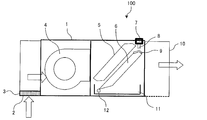
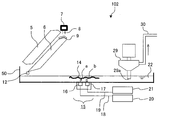
- FIG. 1 is a schematic diagram showing a cross section of an air conditioner 100 according to the present embodiment.
- white arrows indicate the direction of air flow.
- an air conditioner 100 according to the present embodiment supplies a fan 4, a heat exchanger 5, a humidifying material 6, a drain pan 11, and water for humidification into a housing 1. It has a supply unit 7 and has a cooling function, a heating function, and a humidifying function.
- a suction port 2 that opens to the lower surface is formed on one side surface of the housing 1, and an air outlet 10 is formed on the other side surface of the housing 1.
- the air conditioner 100 sucks air from the suction port 2 and blows out the conditioned air that has passed through the heat exchanger 5 from the air outlet 10.
- a filter 3 that removes dust from the air sucked into the housing 1 is disposed above the suction port 2.
- a fan 4 is disposed on the downstream side of the filter 3, and air sucked upward from the suction port 2 passes through the filter 3 and is blown into the inside of the housing 1.
- the heat exchanger 5 is located on the downstream side of the fan 4 and is inclined so that the upstream side of the heat exchanger 5 is a lower end portion and the downstream side is an upper end portion.
- the heat exchanger 5 has a fin-and-tube structure made of aluminum, for example, and heats or cools the air by heat exchange between the air passing through the periphery and the refrigerant flowing through the inside.
- the humidifying material 6 is formed, for example, by standing a plurality of plate-like members in parallel, and is arranged along the inclination of the heat exchanger 5 below the heat exchanger 5 and has a shape deformed by shear deformation.
- the humidifying material 6 has a long side length substantially equal to that of the heat exchanger 5.
- the upper end portion of the humidifying material 6 has a mountain shape on the upper surface, and the diffusion material 9 is placed on the upper surface of the mountain shape.
- a supply unit 7 and a nozzle 8 for supplying water to the humidifying material 6 are disposed, and the humidifying material is interposed via a diffusion material 9 disposed on the upper surface of the humidifying material 6. 6 is supplied with water. Either tap water or industrial water can be used as the water, but it is desirable that the scale components that cause sediments, such as calcium, magnesium, and silica, are small.
- the drain pan 11 is disposed below the heat exchanger 5 and the humidifying material 6 in order to receive the water droplets 12 drained from the heat exchanger 5 or the humidifying material 6.
- the drain pan 11 accumulates water droplets 12 that have naturally flowed down from the heat exchanger 5 and the humidifying material 6 as the drain water 22.
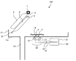
- FIG. 2 is a schematic diagram showing a cross section around the drain pan 11 of the air conditioner 100 according to the present embodiment.
- a drain pipe 13 is connected to the lower surface of the drain pan 11, and a detection unit 15 is disposed.
- the drain pipe 13 discharges the drain water 22 accumulated in the drain pan 11 to the outside. If the amount of water droplets 12 supplied to the drain pan 11 is smaller than the amount of drain water 22 discharged from the drain pipe 13, the drain water 22 does not accumulate in the drain pan 11. If the amount of water droplets 12 supplied to the drain pan 11 is larger than the amount of drain water 22 discharged from the drain pipe 13, the water level of the drain water 22 of the drain pan 11 rises.
- the drain pipe 13 is an example of the discharge part of this invention.
- the detection unit 15 detects the biofilm 14 generated on the upper surface of the drain pan 11, and includes an electric wire 18, a power source 20 connected by the electric wire 19, an amplifier detection circuit 21, an ultrasonic transmitter 16, and an ultrasonic wave
- the detector 17 is configured.
- the biofilm 14 is a composite of an adhesive polysaccharide that is metabolized by bacteria, mold, and the like, and a soil component contained in the air, and is an aggregate having a viscosity called slime.
- the biofilm 14 is generated on the top surface of the drain pan 11 by dripping the water droplets 12 mixed with airborne bacteria and mold spores floating around the air conditioner 100 onto the drain pan 11. If the biofilm 14 adheres to and accumulates on the joint portion or the wall surface of the drain pipe 13 and the drain pan 11, the drain water 22 cannot be discharged. In addition, there is a possibility that bacteria and fungi harmful to the human body propagate on the biofilm 14.
- An example is an aerobic gram-negative bacterium called Legionella spp.
- Legionella is a kind of Legionella spp. And is described as Legionella pneumophila. If Legionella spp. That are bacteria that are resident in the soil and the like are grown on the biofilm 14 and diffused in the air, it becomes a pathogenic risk.
- the biofilm 14 is not allowed to grow as much as possible from the viewpoint of hygiene, and it is recommended that the drain pan 11 be inspected and cleaned once a month, for example, as a periodic inspection.
- the humidified part of the air conditioner 100 is often installed on the ceiling part, and it is difficult to disassemble and clean it.
- the antibacterial agent disappears with time and the effect is lost.
- the detection unit 15 warns whether or not the drain pan 11 needs to be cleaned based on the determination as to whether or not the biofilm 14 has been generated.
- the detection unit 15 transmits an ultrasonic wave in the direction of the arrow a, detects the ultrasonic wave reflected in the direction of the arrow b on the biofilm 14, and determines whether the biofilm 14 generated on the upper surface of the drain pan 11 exists. .
- the detection unit 15 is formed in a structure integrated with the drain pan 11 in order to eliminate a gap portion between the detection unit 15 and the drain pan 11. This is because if there is a gap portion, there is reflection at the interface between air and the solid portion, so that the size of the transmitted ultrasonic wave is reduced and the SN ratio is deteriorated.
- the S / N ratio is an abbreviation for Signal / Noise ratio and is called a signal-to-noise ratio. Since the detection unit 15 has an integrated structure with the drain pan 11, the resonance impedance of the material is uniform at the contact point with the drain pan 11, and the influence of noise on the detection signal is reduced.
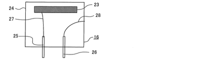
- FIG. 3 is a schematic diagram illustrating the ultrasonic transmitter 16 of the detection unit 15 provided in the drain pan 11 of FIG.
- the ultrasonic transmitter 16 is configured by housing a piezoelectric element 23, an electrode 25, an electrode 26, a lead wire 27, and a lead wire 28 in a housing 24.
- the electrode 25 is electrically connected to the piezoelectric element 23 via a lead wire 27.
- the electrode 26 is electrically connected to the housing 24 via a lead wire 28.
- a high frequency voltage is applied between the electrode 25 and the electrode 26, the piezoelectric element 23 vibrates and generates an ultrasonic wave.
- the piezoelectric element 23 is an example of the ultrasonic element of the present invention.
- the ultrasonic detector 17 has a structure in which the piezoelectric element 23, the electrode 25, the electrode 26, the lead wire 27, and the lead wire 28 are accommodated in the housing 24, similarly to the ultrasonic transmitter 16.
- the ultrasonic detector 17 when vibration derived from the ultrasonic wave is generated in the piezoelectric element 23, it is converted into an electrical signal in which a voltage is generated by the vibration, and is detected by the electrode 25 and the electrode 26. Note that no voltage is applied between the electrode 25 and the electrode 26 constituting the ultrasonic detector 17.
- the ultrasonic transmitter 16 and the ultrasonic detector 17 have the same structure and are housed together in the same casing 24, and the ultrasonic transmitter 16 and the ultrasonic detector 17 are integrally configured. be able to. In this case, one of the two structures transmits as the ultrasonic transmitter 16 and the other receives as the ultrasonic detector 17.
- the transmission method is a pulse wave
- the frequency is an ultrasonic wave of 40 kHz or more and 500 kHz or less.
- An ultrasonic wave generally refers to a sound wave having a frequency of 20 kHz or higher. The higher the ultrasonic frequency, the better the resolution, but on the other hand, there is a trade-off relationship that the reach distance is shortened. Therefore, it is desirable that the frequency of the ultrasonic wave is 300 kHz.
- the transmission method of an ultrasonic wave is not limited to a pulse wave, A continuous wave may be sufficient.
- the wavelength ⁇ is 300 kHz and the speed of sound in the air is 343 m / sec
- the speed of sound 343 / frequency 300 1.1 mm.
- the pulse width may be arbitrary, but if it is too long, detection becomes difficult, so 1 to 5 times the wavelength is appropriate.
- the ultrasonic wave transmitted from the ultrasonic transmitter 16 is applied to the biofilm 14. While the ultrasonic wave has a characteristic of reflecting at the interface of the object, the biofilm 14 has a porous shape.
- the ultrasonic wave transmitted by the ultrasonic transmitter 16 propagates in the air in the direction of the arrow a and reaches the interface of the biofilm 14. Then, due to the characteristics of the ultrasonic wave and the shape of the biofilm 14, the ultrasonic wave that has reached the interface is partially reflected, propagates in the direction of the arrow b, reaches the ultrasonic detector 17, and as a response Detected. Another part of the ultrasonic wave that reaches the interface is not reflected by the biofilm 14 but is transmitted.
- FIG. 4 is a diagram showing a flow of operation of the air conditioner 100 according to the present embodiment.
- the air conditioner 100 has functions of a humidifying operation and an air conditioning operation, and the air humidifying operation and the air conditioning operation are simultaneously or selectively performed according to the required temperature and humidity conditions of the outlet air. Do.
- the air conditioner 100 determines whether or not humidification is performed in Step S1, and determines whether or not the cooling and heating operation is necessary in Step S2.
- step S1 of FIG. 4 when it is determined that humidification is performed and the humidification operation is started, water stored in the supply unit 7 is conveyed to the nozzle 8 above the diffusion material 9 as humidified water.
- the humidified water conveyed to the nozzle 8 is dropped from the tip of the nozzle 8 toward the upper portion of the diffusing material 9, and water is supplied to the humidifying material 6.
- the humidified water is uniformly diffused throughout the humidifying material 6 using the capillary force and gravity of the diffusing material 9, and a certain amount of humidified water is held in the humidifying material 6.
- the fan 4 starts operation.
- the air sucked from the suction port 2 by the operation of the fan 4 passes through the humidifier 6 through the filter 3, the fan 4, and the heat exchanger 5, and enters the outside of the air conditioner 100 with the humidifier, that is, into the room. Be transported.
- the humidified water held in the humidifying material 6 evaporates in contact with the air, humidifies the air, and is transported into the room together with the air.
- Excess humidified water of the humidifying material 6 that has not been evaporated and used for humidification gathers near the lower end of the humidifying material 6 due to gravity, leaks from the lower end of the humidifying material 6 and drops downward.
- the water droplets 12 leaking out and dripping from the humidifying material 6 are supplied to the drain pan 11 and received as drain water 22. Then, the drain water 22 is discharged from the drain pipe 13.
- step S ⁇ b> 2 of FIG. 4 when it is determined that the air conditioning operation is necessary and the air conditioning operation is started, the surface of the heat exchanger 5 is heated or cooled by flowing a heated or cooled refrigerant through the heat exchanger 5. Specifically, during the heating operation, the heated refrigerant flows into the heat exchanger 5, the surface of the heat exchanger 5 is heated, and the air passing through the surface of the heat exchanger 5 is heated. During the cooling operation, the cooled refrigerant flows into the heat exchanger 5, the surface of the heat exchanger 5 is cooled, and the air passing through the surface of the heat exchanger 5 is cooled.
- step S4 it is determined whether or not the drain water 22 has been discharged. At this time, the discharge completion time may be 1 to 2 hours. If it is determined in step S4 that drainage is completed, the presence or absence of the biofilm 14 is detected by the detection unit 15 in step S5, and it is determined whether or not the biofilm 14 exceeds the set value in step S6. In step S6, if the biofilm 14 exceeds the specified value, the process proceeds to step S7 to warn of the drain pan 11 being cleaned. On the other hand, if the biofilm 14 does not exceed the prescribed value in step S6, the process proceeds to step S8, and the operation of the air conditioner 100 is completed, and the air conditioner 100 stops.
- FIG. 5 is a schematic diagram showing a cross section around the drain pan 11 during the humidifying operation or cooling operation of the air conditioner 100 according to the present embodiment.
- the water droplets 12 received by the drain pan 11 in the humidifying operation or the cooling operation are stored in the drain pan 11 as drain water 22.
- drain water 22 is discharged through the drain pipe 13.
- the water droplets 12 are not supplied, while the drain water 22 is discharged from the drain pipe 13, and the draining process of the drain water 22 is completed when a certain time elapses.
- the detection of the biofilm 14 by the detection unit 15 is performed in a state where the drain water 22 does not exist after the humidification operation or the cooling operation of the air conditioner 100 is stopped.
- the humidification operation or the cooling operation is stopped, the supply of the water droplets 12 is stopped, and when a certain time has passed, the drainage of the drain water 22 through the drain pipe 13 is completed.
- the detection unit 15 considers that the discharging process has been completed and starts detecting the biofilm 14.
- the piezoelectric element 23 inside the ultrasonic transmitter 16 vibrates and transmits an ultrasonic pulse wave having a wavelength of 300 kHz.
- the ultrasonic wave propagates in the air in the direction of arrow a and is reflected at the interface between the biofilm 14 and the air.
- the reflected ultrasonic wave propagates in the direction of the arrow b and vibrates the piezoelectric element 23 of the ultrasonic detector 17.
- a voltage is generated between the electrode 25 and the electrode 26, and the amplifier detection circuit 21 detects the voltage as a response from the biofilm 14.
- the detection unit 15 warns the cleaning of the drain pan 11 based on the response detected by the amplifier detection circuit 21.
- FIG. 6 is a graph showing an ultrasonic response in the state of FIG. 2 in which the drain water 22 is discharged.
- the vertical axis indicates the ultrasonic intensity
- the horizontal axis indicates time.
- the peak value is obtained when the ultrasonic wave propagating through the air and reflected at the interface of the biofilm 14 is received by the ultrasonic detector 17 as a response.
- the peak value received by the ultrasonic detector 17 becomes a response by the biofilm 14.
- the detection unit 15 transmits an ultrasonic wave from the ultrasonic transmitter 16 in a state where the drain water 22 is discharged, and the ultrasonic wave reflected by the ultrasonic detector 17 is received and detected as a response. Whether or not the biofilm 14 exists is determined based on whether or not. When the presence of the biofilm 14 is detected, the cleaning of the drain pan 11 is warned. Thereby, the user can know the presence or absence of the biofilm 14.
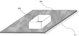
- FIG. 7 is a schematic view of a partition plate 45 for collecting a part of the mixture 44 of the biofilm 14 and the drain water 22.
- a constant area region on the bottom surface of the drain pan 11 was divided by a partition plate 45, and the change in the amount of water per unit area of the mixture of the biofilm 14 and the drain water 22 was verified.
- the partition plate 45 has a rectangular hollow shape, and separates the mixture 44 by standing on the drain pan 11.
- the area to be divided is a sampling area, and may be arbitrary such as 5 cm ⁇ 5 cm.
- the mixture 44 divided by the partition plate 45 was all sucked up with a dropper, and the total weight of the collected mixture 44 was measured.
- FIG. 8 is a graph showing a change in the amount of moisture per unit area of the mixture 44 of the biofilm 14 and the drain water 22 after the humidification operation of the air conditioner 100 is stopped.
- the horizontal axis indicates the elapsed time after the humidification operation is stopped, and the vertical axis indicates the amount of moisture per unit area.
- the biofilm 14 was produced on the bottom surface of the drain pan 11 by repeating a cycle in which the humidification operation was continuously operated for 6 hours and then stopped for 18 hours for 60 days. Then, the humidification operation was continuously operated for 6 hours, so that the biofilm 14 was immersed in the drain water 22 and the biofilm 14 was not exposed to the space.
- the elapsed time in this state is set to 0 minute, the moisture amount per unit area of the mixture 44 of the biofilm 14 and the drain water 22 is calculated by the above method, and the moisture amount per unit area with the elapsed time is measured. did.
- the water content of the mixture 44 of the biofilm 14 and the drain water 22 was 110 mg / cm 2 at an elapsed time of 0 minutes, that is, immediately after the humidification operation was stopped. And with the passage of time, the water level of the drain pan 11 was lowered by the drain pipe 13, and the amount of water per unit was rapidly lowered to 50 mg / cm 2 in 20 minutes. The transition of the elapsed time of 20 minutes was almost a steady state with a water content of 50 mg / cm 2 , and at the elapsed time 120, it was 48 mg / cm 2 , which was almost the same value.
- the biofilm 14 was immersed in the drain water 22 at an elapsed time of 0 minutes, and the biofilm 14 was not exposed on the surface. On the other hand, after the elapsed time of 20 minutes, the biofilm 14 was exposed to the air.
- Ultrasonic measurement can be performed without any problem if the amount of water per unit area is in the range of 0 to 50 mg / cm 2 , but when it exceeds 50 mg / cm 2 , the biofilm 14 is immersed in water, It is affected by the interface of the drain water 22. That is, it is possible to exclude the influence of the interface of the drain water 22 by measuring ultrasonic waves with a water amount per unit area within 50 mg / cm 2 . Therefore, the ultrasonic measurement may be performed by determining that the discharging process is completed within an elapsed time of 20 minutes. However, since the drainage speed varies depending on the size of the drainage pipe 13 and the inclination of the drain pan 11, the time for completing the drainage process may be changed according to the drainage characteristics. Alternatively, a time region in which the amount of moisture per unit area is sufficiently in a steady state may be obtained in advance, and that time may be substituted for the time for completing the drainage process.
- the rate of change in the amount of water per unit area from the elapsed time of 20 minutes to the elapsed time of 30 minutes was 4%.
- the rate of change in the amount of water per unit area after 10 minutes is 4% or less, it can be considered that a steady state has been reached.
- an elapsed time until the steady state is obtained is obtained in advance, and after the obtained elapsed time has elapsed, it is considered that the drainage process is completed, and ultrasonic measurement may be performed.
- the bottom surface of the drain pan 11 is made of plastic, it is usually water-repellent.
- the drain water 22 is in the form of water droplets. From this, when the drain water 22 exists only in a part of the bottom of the drain pan and water droplets exist discretely, it may be considered that the draining process of the drain water 22 is completed.
- the elapsed time until a water droplet having a diameter of 20 mm or less is present on the bottom surface of the drain pan 11 may be obtained in advance, and it may be considered that the drainage process is completed at that time.
- a plurality of water detection sensors that detect a change in resistance between electrodes that are commercially available as water leakage detectors may be arranged on the upper surface of the drain pan 11. In this case, it can be considered that the drainage process of the drain water 22 is completed when the output of each water detection sensor decreases or when the variation becomes large.
- the ultrasonic wave is reflected on the bottom surface of the drain pan 11 and reaches the detection unit 15.
- the material of the drain pan 11 is a plastic such as ABS, and the acoustic impedance is higher than that of the biofilm 14 or water, and the smoothness is high, so that the ultrasonic reflectivity is high.
- the biofilm 14 has large unevenness and has a property of easily scattering ultrasonic waves.
- the biofilm 14 can be quantified by measuring the ultrasonic intensity in the state where neither the biofilm 14 nor the drain water 22 exists, and measuring how much the ultrasonic wave is scattered based on the ultrasonic intensity.
- the water interface also has the property of scattering or reflecting ultrasonic waves in the same manner as the biofilm 14, but since the unevenness is smaller than that of the biofilm 14, it is less than the ultrasonic waves scattered by the biofilm 14 and has a great influence on measurement. Not give.
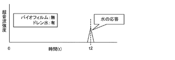
- FIG. 9 is a schematic diagram showing a state in which drain water 22 is accumulated in the drain pan 11 of the air conditioner 100 according to the present embodiment.
- the ultrasonic wave when an ultrasonic wave is transmitted from the ultrasonic transmitter 16 with the drain water 22 accumulated in the drain pan 11, the ultrasonic wave propagates in the drain water 22 in the direction of the arrow c, The water surface of water 22 is reached. Then, the ultrasonic wave reflected at the interface between the drain water 22 and air propagates in the direction of the arrow d and is detected as a response by the ultrasonic detector 17.
- FIG. 10 is a graph showing an ultrasonic response in the state of FIG. 9 in which drain water 22 is accumulated in the drain pan 11.
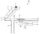
- FIG. 11 is a schematic diagram showing a state in which the biofilm 14 is generated and the drain water 22 is accumulated in the drain pan 11 in the air conditioner 100 according to the present embodiment.
- the biofilm 14 generated above the drain pan 11 is immersed in the drain water 22 due to the rise in the water level of the drain water 22.
- the ultrasonic wave propagates in the drain water 22 in the direction of arrow a.
- FIG. 12 is a graph showing an ultrasonic response in the state of FIG. 11 in which the biofilm 14 is generated and the drain water 22 is accumulated in the drain pan 11.
- the two peak values appear close to each other and cannot be identified. In this case, it becomes impossible to identify whether or not the biofilm 14 exists.
- whether or not the biofilm 14 is accumulated may be determined by setting a certain threshold value and determining whether the biofilm 14 is above or below that value. For example, the ultrasonic intensity when neither the biofilm 14 nor the drain water 22 is present is P0, and the ultrasonic intensity measured after the humidifying operation or the cooling / heating operation is P1. Then, when the difference P0-P1 exceeds a certain value, that is, when the threshold value is exceeded, it can be determined that the biofilm 14 has accumulated.
- the measurement was performed when a certain period of time had elapsed from the end of the humidification operation or cooling operation and the discharge process was completed, but other methods are possible as long as the measurement can be performed without any interference with the water level of the drain water 22. It is. For example, the same effect can be obtained even if the biofilm 14 is measured after a heater is installed in the vicinity of the ultrasonic detector 17 and heated at the end of the humidifying operation or cooling operation to evaporate the drain water 22.
- the detection unit 15 starts from the ultrasonic transmitter 16. Send ultrasonic waves. Then, it is detected whether or not a response is received by the ultrasonic detector 17, and the presence or absence of the biofilm 14 is determined based on the detection result. Therefore, it is prevented that the ultrasonic waves reflected by objects other than the biofilm 14 such as the water surface of the drain pan 11 are due to the biofilm. Thereby, it is possible to output a warning to the user based on the detected ultrasonic wave, and it becomes easy to determine whether or not a biofilm exists.
- the drain pan 11 is in a state where drainage is completed after a certain time has elapsed after the cooling operation or the humidifying operation is completed.
- the biofilm 14 can be detected in a state where the drain water 22 is completely discharged.
- the detection unit 15 includes an ultrasonic transmitter 16 that transmits ultrasonic waves, and an ultrasonic detector 17 that detects ultrasonic waves transmitted by the ultrasonic transmitters. It is equipped with. Since the ultrasonic transmitter 16 transmits an ultrasonic wave in a state where the discharge of water has been completed, the ultrasonic wave detected by the ultrasonic detector 17 may be specified as the ultrasonic wave reflected by the biofilm 14. it can.
- the detection unit 15 is provided below the drain pan 11, it is possible to prevent the detection result from being misidentified due to a response from other than the drain pan 11. .
- the ultrasonic detector 17 detects the ultrasonic wave reflected by the biofilm 14
- the ultrasonic transmitter 16 and the ultrasonic detector 17 are adjacent to each other. , It can be an integral structure.
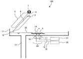
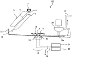
- FIG. FIG. 13 is a schematic diagram showing a cross section around the drain pan 50 of the air conditioner 102 according to the present embodiment.
- the drain pan 50 according to the present embodiment is different from the first embodiment in that it includes a drain pump 29 and a drain drain pipe 30.
- the drain pan 50 is applied to an arrangement place where natural drainage by gravity through the drain pipe 13 of the first embodiment is difficult. Since other configurations are the same as those of the first embodiment, description thereof is omitted.
- the drain pump 29 is, for example, a pump with a propeller that operates by electricity, and is disposed above the drain pan 50 to suck up the drain water 22 of the drain pan 50 from the suction portion 29a.
- the drain drain pipe 30 is connected to the drain pump 29 and discharges the drain water 22 sucked up by the drain pump 29 to the outside.
- the drain pump 29 and the drain drain pipe 30 are another example of the discharge part of the present invention.
- the drain water 22 accumulated in the drain pan 50 is forcibly sucked up from the drain pan 50 by the power of the drain pump 29 and discharged to the outside through the drain drain pipe 30.
- the air conditioner 102 when the air conditioner 102 performs the humidifying operation or the cooling operation as in the first embodiment, the water droplets 12 leaked from the humidifying material 6 without being used for humidification or the heat exchanger 5
- the condensed water generated in the surroundings is received by the drain pan 50 as the drain water 22.
- the drain water 22 is pumped up by the operation of the drain pump 29 and is discharged through the drain drain pipe 30 without accumulating in the drain pan 50, and the discharged water 22 is maintained in a discharged state in which the water level is lower than that of the suction portion 29a.
- the state shown in FIG. 13 is drained from the drain pan 50 by the operation of the drain pump 29.
- the detection unit 15 vibrates the piezoelectric element 23 inside the ultrasonic transmitter 16 and transmits an ultrasonic pulse wave having a wavelength of 300 kHz.
- the ultrasonic wave propagates in the direction of the arrow a in the air and reaches the biofilm 14, it is reflected at the interface between the biofilm 14 and the air.
- the ultrasonic wave propagates in the direction of the arrow b and passes through the ultrasonic detector 17.
- the piezoelectric element 23 is vibrated to generate a voltage between the electrode 25 and the electrode 26, and is detected as a response from the biofilm 14 in the amplifier detection circuit 21.
- the detection unit 15 warns that the drain pan 50 is cleaned, assuming that the biofilm 14 exists.
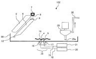
- FIG. 14 is a schematic diagram showing a cross section around the drain pan 50 in a state where the humidification operation or the air conditioning operation of the air conditioner 102 according to the present embodiment is finished and the power supply is stopped.
- the operation of the drain pump 29 is also stopped at night when the humidification operation or the air conditioning operation ends and the power supply is stopped.
- the drain water 22 deposited on the drain pump 29 and the drain drain pipe 30 falls to the drain pan 50 due to gravity, and the biofilm 14 is immersed in the drain water 22.
- an ultrasonic wave is transmitted from the ultrasonic transmitter 16 in this state, two peak values are detected by the ultrasonic detector 17 and it is impossible to detect the presence or absence of the biofilm 14.
- the detection unit 15 does not operate.
- the air conditioner 102 is in an operating state, the driving of the drain pump 29 is started, drainage of the drain water 22 is restarted, the drain pan 50 is discharged, and the detection unit 15 detects the biofilm 14. Can do.
- the drain pan 50 is not immediately drained and a time difference occurs. That is, in the initial state, the biofilm 14 is immersed in the drain water 22 and is in a submerged state, and the water level decreases with the passage of time and the biofilm 14 is exposed to the air. Therefore, also in the discharge process due to the operation of the drain pump 29, it is possible to similarly grasp the change in the amount of water per unit area as shown in FIG. 7 of the first embodiment. As in the first embodiment, after a certain time has elapsed, that is, after the steady state is reached, the detection of the biofilm 14 can eliminate the influence of the interface of the drain water 22, so Preferred for operation.
- the air conditioner 102 includes a drain pump 29 that is provided above the drain pan 50 and sucks up water, and a drain drain pipe 30 that discharges water. Therefore, even during the humidifying operation or the air conditioning operation, the biofilm 14 is not immersed in the drain water 22, and the presence or absence of the biofilm 14 is detected without misidentifying that it is a detection result by the water surface of the drain water 22. Is possible.
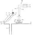
- FIG. 15 is a schematic diagram showing a cross section around the drain pan 51 of the air conditioner 103 according to the present embodiment.
- the drain pan 51 has a region that is inclined with respect to the horizontal plane so that the bottom surface of the drain pan 51 is lowest immediately below the drain pump 29 disposed above the drain pan 51. This is different from the first and second embodiments. Since other parts are the same as those in the first and second embodiments, description thereof is omitted.
- the drain pan 51 includes a detection unit 15 disposed on the lower surface of the drain pan 51, a drain pump 29 disposed on the upper portion, and an inclined bottom surface.
- the horizontal position of the suction part 29 a of the drain pump 29 is arranged at a position lower than the horizontal position of the detection part 15 with the ultrasonic detector 17.
- FIG. 16 is a schematic diagram illustrating a cross section of the periphery of the drain pan 51 during the humidifying operation or the cooling operation of the air conditioner 103 according to the present embodiment.
- the water droplets 12 that are not used for humidification and leak from the humidifying material 6 or the condensed water generated around the heat exchanger 5 is received as drain water 22 by the drain pan 50.
- the drain water 22 whose water level has gradually increased reaches the suction part 29a of the drain pump 29, it is pumped up by the drain pump 29, discharged through the drain drain pipe 30, and the water level of the drain water 22 is higher than that of the suction part 29a. Maintained.
- the detection unit 15 transmits an ultrasonic pulse wave in the direction of the arrow a by the ultrasonic transmitter 16 and detects the response of the ultrasonic wave that reaches the biofilm 14 and is reflected.
- the detection unit 15 warns that the drain pan 11 is cleaned, assuming that the biofilm 14 exists.
- the drain water 22 on the upper portion of the detection portion 15 is caused to flow by the drain pump 29. It will be completely discharged. Thereby, the drain water 22 does not accumulate in the upper part of the detection part 15, and the presence or absence of the biofilm 14 can be detected without being affected by the water surface of the drain water 22 by the ultrasonic wave.
- the drain pan 51 is inclined at the same angle in one direction. However, the drain pan 51 only needs to be disposed at the lowest position in the region immediately below the suction portion 29a of the drain pump 29. It may be inclined in a plurality of directions and angles.
- the drain pan 51 has a region inclined with respect to the horizontal plane. Therefore, it is possible to make the height of the drain pan 51 directly below the suction portion 29 a of the drain pump 29 coincide with the height of the drain pan 51 on the upper portion of the detection unit 15. A lot can be discharged.
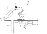
- FIG. 17 is a schematic diagram showing the periphery of the drain pan 52 of the air conditioner 104 according to the present embodiment. As shown in FIG. 17, the present embodiment is different from the first to third embodiments in that a scattering plate 31 is disposed above the drain pan 52. The other parts are the same as those in the first to third embodiments, and thus the description thereof is omitted.
- the scattering plate 31 is installed at an angle ⁇ with respect to the horizontal direction.
- the scattering plate 31 is an example of the reflection plate of the present invention.
- the angle ⁇ depends on the directivity of the ultrasonic transmitter 16, but is preferably 30 degrees or more.
- the material of the scattering plate 31 is preferably a sound-absorbing material, for example, a urethane-based or styrene-based foam material. Further, the angle ⁇ may be set to 0 degree, and the material of the scattering plate 31 may be composed of a sound absorbing material having no reflectivity, such as rock wool or glass wool.
- the detection unit 15 may be installed with the angle inclined without setting the transmission direction of the ultrasonic transmitter 16 and the reception direction of the ultrasonic detector 17 to be the vertical direction.
- FIG. 18 is a schematic diagram illustrating a state during operation of the detection unit 15 of the air conditioner 104 according to the present embodiment.
- a part of the ultrasonic waves transmitted from the ultrasonic transmitter 16 passes through the biofilm 14 and proceeds in the direction of the arrow c.
- the ultrasonic waves are reflected by the scattering plate 31 and travel in the direction of the arrow d.
- Ultrasound that has passed through the biofilm 14 and has been reflected by something other than the biofilm 14 is prevented from reaching the ultrasound detector 17. As a result, noise that interferes with measurement by the ultrasonic detector 17 is reduced, and measurement with higher accuracy can be performed.
- ultrasonic wave having a high frequency In general, high frequency ultrasonic waves have high directivity. When ultrasonic waves with low directivity are transmitted, there is a possibility that the ultrasonic waves transmitted through the biofilm 14 are reflected at a place other than the scattering plate 31 and detected by the ultrasonic detector 17. On the other hand, by transmitting ultrasonic waves with high directivity from the ultrasonic transmitter 16, the ultrasonic waves transmitted through the biofilm 14 are reflected by the scattering plate 31 and reflected by the biofilm 14 at the ultrasonic detector 17. Only the ultrasonic waves that have been transmitted will be detected.
- drain pipe 13 connected to the drain pan 52 is discharged
- drain pump 29 and the drain drain pipe 30 are provided in the upper part of the drain pan 52.
- the present embodiment can also be applied to the configuration.
- the scattering plate 31 is provided above the detector.
- the ultrasonic wave that has passed through the biofilm 14 is reflected by the scattering plate 31 in a direction other than the ultrasonic detector 17, and the ultrasonic detector 17 does not detect a response in which noise is mixed. It becomes possible to do.
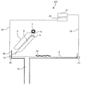
- FIG. 19 is a schematic diagram showing a cross section around the drain pan 53 of the air conditioner 105 according to the present embodiment.
- the detection unit 15 is arranged above the drain pan 53, and the space between the drain pan 53 and the detection unit 15 is a space. Is different. Since other parts are the same as those in the first to fourth embodiments, description thereof will be omitted.
- the detection unit 15 is disposed so that the directions of the ultrasonic transmitter 16 and the ultrasonic detector 17 face the bottom surface of the drain pan 53.
- the ultrasonic transmitter 16 transmits ultrasonic waves in the direction of the bottom surface of the drain pan 53, and the ultrasonic detector 17 detects ultrasonic waves that have arrived from the direction of the drain pan 53.
- the detection unit 15 When the detection unit 15 finishes the humidifying operation or cooling operation of the air conditioner 105 and a certain time has elapsed and the drainage of the drain water 22 from the drain pipe 13 connected to the drain pan 53 is completed, the detection unit 15 transmits ultrasonic waves. An ultrasonic wave is transmitted from the vessel 16. The ultrasonic wave is reflected by the biofilm 14 existing in the transmission direction, reaches the ultrasonic detector 17 and is detected as a response. When the ultrasonic detector 17 detects the peak value of the response due to the ultrasonic wave reflected by the biofilm 14, the detection unit 15 warns that the biofilm 14 exists.
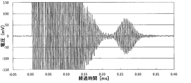
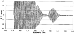
- FIG. 20 is a diagram showing experimental results in the initial state of the air conditioner 105 according to the present embodiment, and is a graph showing the relationship between voltage and elapsed time when ultrasonic waves are transmitted from the ultrasonic transmitter 16. It is.
- the voltage indicates the voltage detected by the amplifier detection circuit 21, and the elapsed time indicates the elapsed time when the ultrasonic wave is transmitted at 0 ms.
- the change in voltage in the range of elapsed time of 0.23 to 0.32 ms corresponds to the ultrasonic wave reflected from the drain pan 53. Note that the change in voltage up to the elapsed time of 0.2 ms is derived from the resonance phenomenon of the detection unit 15.
- the voltage in the range of the elapsed time of 0.23 to 0.32 ms fluctuates between plus and minus, and the ultrasonic intensity cannot be calculated as it is. Therefore, time integration was performed after squaring a voltage in the range of elapsed time of 0.23 to 0.32 ms, and an ultrasonic intensity P0 was obtained.
- the unit of the ultrasonic intensity P0 is (mV) 2 * ms.
- FIG. 21 is a diagram showing a test result before draining of the air conditioner 105 according to the present embodiment.
- the voltage and elapsed time when the ultrasonic wave is transmitted from the ultrasonic transmitter 16 Shows the relationship.
- the voltage change of the amplifier detection circuit 21 was confirmed in the range of the elapsed time of 0.23 to 0.32 ms, as in FIG.
- the fall of the absolute value of the voltage was not confirmed from the comparison with FIG. This is due to the influence of the drain water 22, and the accumulation of the biofilm 14 could not be determined.
- FIG. 22 is a diagram showing an experimental result after drainage of the air conditioner 105 according to the present embodiment.
- the graph shows the relationship between the voltage and the elapsed time when ultrasonic waves are transmitted from the ultrasonic transmitter 16 at a time point 20 minutes after the humidification operation is stopped, that is, after the drainage of the drain pan 11 is confirmed.
- the voltage change of the amplifier detection circuit 21 was confirmed in the range of the elapsed time of 0.23 to 0.32 ms, as in FIG.
- the absolute value of the voltage was lowered, and the ultrasonic waves scattered by the biofilm 14 could be confirmed without being affected by the drain water 22. Therefore, time integration was performed after squaring the voltage change in the range of elapsed time of 0.23 to 0.32 ms, and the ultrasonic intensity P was obtained.
- FIG. 23 is a diagram showing the ultrasonic intensity P according to the present embodiment and the change over time in the amount of water per unit area.
- the ultrasonic intensity is represented by a solid line
- the amount of water per unit area is represented by a broken line.
- the elapsed time of 0 minutes indicates the time when the humidification operation is completed
- the elapsed time indicates the time that has elapsed since the completion of the humidification operation.
- the method for calculating the amount of moisture per unit area is the same as the method described in the first embodiment.
- the ultrasonic intensity is 54 (mV) 2 * ms, and since the water is drained with the elapsed time, the ultrasonic intensity gradually decreases. In 20 minutes after stopping the humidification operation, it became 21.1 (mV) 2 * ms. After that, it became a constant value of approximately 21 (mV) 2 * ms. In addition, the amount of water per unit area also shows the same tendency as the ultrasonic intensity, decreases to 55 mg / cm 2 20 minutes after stopping the humidification operation, and thereafter becomes a constant value of 55 mg / cm 2. Showed a similar trend.
- the time after 20 minutes after stopping the humidification operation is regarded as the completion of the discharge process, and the ultrasonic intensity measured in the time region may be set as the ultrasonic intensity P1 after the humidification operation or the air conditioning operation. It turned out to be appropriate.
- the time when the discharging process was completed was a time when the amount of water per unit area was considered to be constant, and the time when the rate of decrease in the amount of water per unit area became 5% or less in 10 minutes.
- the threshold Ps was set to 30 (mV) 2 * ms as the ultrasonic intensity.
- the threshold value Ps corresponds to an allowable amount of the deposited biofilm 14 and changes depending on the amount of the accumulated biofilm 14, and thus the ultrasonic intensity corresponding to the actually measured amount of the biofilm 14 was obtained in advance.
- the threshold value was set with the correlation formula of the quantity of the biofilm 14 and ultrasonic intensity
- the measured amount of biofilm 14 was 1 to 10 mg / cm 2 .
- the difference between the ultrasonic intensity P0 when the biofilm 14 is not present and the ultrasonic intensity P1 after the humidifying operation is compared with the threshold value Ps. If the difference is larger than the threshold value Ps, the biofilm 14 is It is judged that it exists and is deposited.
- FIG. 24 is a schematic diagram illustrating a modification of the periphery of the drain pan 53 of the air conditioner 105 according to the present embodiment.
- a part of the bottom surface of the drain pan 53 is inclined in a direction that does not face the detection unit 15.
- the ultrasonic wave transmitted from the detector 15 travels in the direction of arrow e, is reflected by the drain pan 53, and travels in the direction of arrow f instead of the direction of the ultrasonic detector 17.
- the ultrasonic wave reflected by the biofilm 14 existing between the detection unit 15 and the drain pan 53 reaches the ultrasonic detector 17, and the ultrasonic wave reflected by the drain pan 53 is excluded.
- the transmission direction of the ultrasonic wave is the bottom surface of the drain pan 53
- reflection from the bottom surface of the drain pan 53 is also detected.
- the ultrasonic wave is transmitted. The influence can be excluded.
- the transmission direction of the ultrasonic transmitter 16 and the reception direction of the ultrasonic detector 17 may be inclined from the vertical direction instead of the vertical direction.
- the part of the range where the ultrasonic wave of the drain pan 53 is irradiated is configured by the sound absorbing material, and the ultrasonic wave reflected from the drain pan 53 in the range where the sound absorbing material is provided can be reduced.
- the drain water 22 is discharged by the drain pipe 13 connected to the drain pan 52 as an example.
- the drain water 22 is applied to a configuration in which the drain pump 29 and the drain drain pipe 30 are provided on the drain pan 52. You can also.
- the detection unit 15 is provided above the drain pan 53. Thereby, the biofilm 14 can be detected without being affected by the water surface of the drain water 22, and the degree of freedom of arrangement of the detection unit 15 can be improved.
- FIG. 25 is a schematic diagram showing a cross section around the drain pan 54 of the air conditioner 106 according to the present embodiment.
- the present embodiment is different from the first to fifth embodiments in that a water level sensor 32 is installed on the upper surface of the bottom surface of the drain pan 54. Since other parts are the same as those in the first to fifth embodiments, the description thereof will be omitted.
- the water level sensor 32 is connected to the power source 20 via the electric wire 18 and constantly monitors the water level of the drain water 22 accumulated in the drain pan 54. When the water level sensor 32 detects that the water level has become equal to or less than a certain value, the detection unit 15 starts detection as a state in which the drain water 22 has been discharged.
- a switch type device using a float may be used as the water level sensor 32.
- the float type switch type device has been described as an example of the water level sensor 32, but an ultrasonic reflection type or infrared reflection type device may also be used. Further, the installation position of the water level sensor 32 may be anywhere as long as it is the upper surface portion of the bottom surface of the drain pan 53. Furthermore, the drain water 22 may be configured to be discharged by the drain pump 29 and the drain drain pipe 30 disposed on the drain pan 52.
- the water level sensor 32 is provided on the upper surface of the drain pan 53, and if the water level of the drain water 22 is zero or an approximate value of zero, the drain water 22 It is detected that the discharge is complete. Since the detection unit 15 starts detection of the biofilm 14 based on the detection result of the water level sensor 32, the detection unit 15 can detect the biofilm 14 without being affected by the water surface of the drain water 22.
- FIG. 26 is a schematic diagram showing a cross section around the drain pan 55 of the air conditioner 107 according to the present embodiment.
- the ultrasonic transmitter 16 and the ultrasonic detector 17 are separated from each other on both sides of the drain pan 55 in the first to the first embodiments. 6 and different. Since other parts are the same as those in the first to sixth embodiments, description thereof will be omitted.
- the ultrasonic transmitter 16 is disposed outside one side plate of the drain pan 55, and the ultrasonic detector 17 is disposed opposite the ultrasonic transmitter 16 outside the other side plate of the drain pan 55. .
- the ultrasonic transmitter 16 and the ultrasonic detector 17 are separated and do not have an integral structure.
- the ultrasonic transmitter 16 transmits ultrasonic waves in the direction of the ultrasonic detector 17, that is, in the direction of the arrow g.
- a drain pipe 13 for discharging the drain water 22 is connected to the drain pan 55.
- the detection unit 15 warns that the biofilm 14 exists in the drain pan 55.
- the drain water 22 is discharged from the drain pipe 13 connected to the drain pan 55.
- the drain pump 29 and the drain drain pipe 30 may be provided.
- the drain pump 29 and the drain drain pipe 30 are disposed at positions that do not hinder the ultrasonic propagation path.
- the ultrasonic detector 17 detects ultrasonic waves transmitted through the biofilm 14 from the ultrasonic waves transmitted from the ultrasonic transmitter 16. Thereby, based on the intensity
- FIG. 27 is a schematic diagram showing a cross section around the drain pan 56 of the air conditioner 108 according to the present embodiment.
- the drain pan 56 of the present embodiment is different from those of the first to seventh embodiments in that an optical detection unit 34 including an LED 35 and a photodiode 36 is provided. Since other parts are the same as those in the first to seventh embodiments, description thereof is omitted.
- LED is an abbreviation for Light Emitting Diode, which is an English name of a light emitting diode.
- the biofilm 14 is an aggregate having a viscosity in which bacteria, molds, other adhesive polysaccharides that they metabolize, and dirt components contained in the air are combined. It is known that materials generated by metabolic functions such as biofilm 14 have a fluorescent substance. Examples of such substances include riboflavin, tryptophan, and nicotinamide adenine dinucleotide using the abbreviation for NADH. These substances have a property of emitting fluorescence when irradiated with light of 300 to 450 nm, that is, excitation light. This property is not seen in non-microbial.
- the optical detection unit 34 pays attention to the fluorescence characteristics of riboflavin contained in the biofilm 14 and detects the presence or absence of the biofilm 14 based on whether or not fluorescence is detected by irradiation with excitation light. Specifically, excitation light having a central wavelength of 360 nm, which is 365 nm as the excitation wavelength of riboflavin and 445 nm as the fluorescence wavelength, is irradiated.
- the optical detection unit 34 is disposed above the drain pan 56, and includes an LED 35 connected to the power source 20 by the electric wire 18 and a photodiode 36 connected to the amplifier detection circuit 21 by the electric wire 19.
- the LED 35 generates excitation light having a wavelength of 360 nm
- the photodiode 36 detects fluorescence emitted from the biofilm 14 by the excitation light emitted from the LED 35.
- As the LED 35 an LED that emits light having a center wavelength of 360 nm is used.
- the photodiode 36 preferably includes a filter that removes light in the vicinity of 360 nm in order to eliminate the influence of noise caused by light having a wavelength of 360 nm of the LED 35.
- the optical detection unit 34 emits excitation light from the LED 35.
- Excitation light having a wavelength of 360 nm propagates in the direction of arrow a and reaches biofilm 14.
- the biofilm 14 irradiated with the excitation light emits fluorescence having a wavelength of about 445 nm due to the fluorescence characteristics of riboflavin contained in the biofilm 14.
- the fluorescence propagates in the direction of the arrow b and is received by the photodiode 36 to generate a voltage.
- the voltage is detected by the amplifier detection circuit 21.
- the excitation light emitted from the LED 35 does not reach the biofilm 14
- the excitation light is applied to the bottom surface of the drain pan 56. Since the drain pan 56 does not exhibit fluorescence characteristics, the fluorescence is not emitted even when the excitation light is irradiated.
- the excitation light reflected by the drain pan 11 is excluded by the filter in the photodiode 36.
- LED35 it can replace with a light emitting diode and can also use a semiconductor laser etc., for example.
- a photomultiplier may be used as a light receiving element for detecting light. In the case of light, as in the case of ultrasonic waves, it is desirable to perform detection in the absence of drain water 22 because reflection and scattering are caused by the water surface.
- the LED 35 uses an LED that emits ultraviolet light, visible light, or infrared light, and the photodiode 36 does not include a filter for removing light. Since other parts are the same as those in the eighth embodiment, description thereof is omitted.
- the biofilm 14 shows optical reflection characteristics different from the drain pan 11.
- the LED 35 emits ultraviolet light, visible light, or infrared light, and the presence or absence of the biofilm 14 is detected from the reflection characteristics of the light detected by the photodiode 36.
- the drain water 22 is discharged from the drain pipe 13 connected to the drain pan 55.
- the drain pump 29 and the drain drain pipe 30 may be provided.
- the optical detection unit 34 including the LED 35 and the photodiode 36 is provided above the drain pan 53, and the drain water 22 is discharged. Detection of the biofilm 14 is performed. Thereby, the fluorescence generated by the excitation light emitted from the LED 35 can be detected by the photodiode 36 without being affected by the drain water 22.
- FIG. 28 is a schematic diagram showing a cross section around the drain pan 57 of the air conditioner 109 according to the present embodiment.
- the first embodiment is that a crystal resonator detector 37 composed of a crystal resonator 38 and a sensitive film 39 is provided on the lower surface of the drain pan 57. Different from ⁇ 8. Since other parts are the same as those in the first to eighth embodiments, the description thereof is omitted.
- the crystal resonator detection unit 37 includes a sensitive film 39 provided on the top surface of the bottom surface of the drain pan 57 and a crystal resonator 38 provided on the bottom surface of the bottom surface of the drain pan 57.
- the crystal resonator 38 is electrically connected to the power source 42 by the electric wire 40 and is electrically connected to the frequency analyzer 43 by the electric wire 41.
- the sensitive film 39 is made of a material having high affinity with the biofilm 14 such as polyolefin resin.
- the crystal resonator detecting unit 37 operates the power source 42 to transmit the crystal resonator 38.
- the resonance frequency is measured by the frequency analyzer 43 via the electric wire 41.
- the sensitive film 39 reduces the resonance frequency of the crystal unit 38 due to the biofilm 14 being attached. Therefore, when a decrease in the resonance frequency of the crystal resonator 38 is detected, it is determined that the biofilm 14 is present, and a warning is output.
- the drain water 22 is discharged from the drain pipe 13 connected to the drain pan 55.
- the drain pump 29 and the drain drain pipe 30 may be provided.
- the crystal resonator detection unit 37 configured by the crystal resonator 38 and the sensitive film 39 is provided on the bottom surface of the drain pan 53, and the drain water 22 Is discharged, the biofilm 14 is detected. Thereby, when the biofilm 14 adheres to the sensitive film 39, the resonance frequency of the crystal resonator 38 is lowered, and the biofilm 14 can be detected without being affected by the drain water 22.
Abstract
An air conditioner capable of detecting the presence of a bio-film without being affected by the water surface. An air conditioner for performing at least a cooling operation or a humidifying operation, wherein the air conditioner is provided with a drain pan for receiving water, a discharge unit for discharging the water received by the drain pan, and a detection unit for detecting the bio-film produced in the drain pan. The detection unit performs bio-film detection when the discharge of water in the drain pan has been completed.
Description
本発明は、空気調和機に関し、特に、ドレンパンに生成されるバイオフィルムを検出する空気調和機に関するものである。
The present invention relates to an air conditioner, and more particularly to an air conditioner that detects a biofilm generated in a drain pan.
一般に、例えば、特許文献1に記載された空気調和機のように、熱交換器と、熱交換器から流下するドレン水を受けるドレンパンと、ドレンパンに溜まったドレン水を汲み上げて排出ドレンポンプとを備える空気調和機が知られている。
In general, for example, like an air conditioner described in Patent Document 1, a heat exchanger, a drain pan that receives drain water flowing down from the heat exchanger, a drain water pump that pumps up drain water accumulated in the drain pan, and An air conditioner provided is known.
また、加湿エレメントなどを用いた加湿機能を備えた空気調和機の一種である加湿付全熱交換型換気装置として、例えば、特許文献2に記載された空気調和機がある。加湿付全熱交換型換気装置においては、加湿で使われなかった加湿水を受けるドレンパンに溜まったドレン水はドレン配管の配管勾配により外部へ自然排出されるか、あるいはドレンポンプにより強制的に外部へ排出されている。
Further, as a humidified total heat exchange type ventilator which is a kind of air conditioner having a humidifying function using a humidifying element or the like, for example, there is an air conditioner described in Patent Document 2. In a humidified total heat exchange type ventilator, drain water collected in the drain pan that receives humidified water that has not been used for humidification is naturally discharged to the outside due to the piping gradient of the drain piping, or is forced to the outside by a drain pump. Have been discharged.
いずれの方法においても、ドレンパンに貯溜したドレン水に微生物が繁殖すると、バイオフィルムと呼ばれる半固形状のヌメリが発生する。バイオフィルムは、ドレンポンプやドレンホースを詰まらせるおそれがあり、衛生面でも好ましいものではない。また、ドレンパンは、排水受けとも呼ばれ、建築物衛生法で法定点検の対象であることから、定期的な清掃やメンテナンスを実施する必要がある。更に、ドレンパンは、空気調和機の内部でドレンポンプ等と一体として構成されており、清掃、メンテナンス等は、空気調和機を分解して行う必要があるため、例えば、天井裏などに空気調和機が配置されていると、非常に手間とコストがかかってしまう。
In any method, when microorganisms propagate in the drain water stored in the drain pan, a semi-solid slime called biofilm is generated. A biofilm may clog a drain pump or a drain hose and is not preferable in terms of hygiene. Drain pans are also called drain receptacles and are subject to legal inspections under the Building Sanitation Law, so regular cleaning and maintenance are required. Furthermore, the drain pan is configured integrally with a drain pump or the like inside the air conditioner, and cleaning, maintenance, etc. need to be performed by disassembling the air conditioner. If it is arranged, it will be very troublesome and costly.
特許文献3では、配管内の内面付着物の検出方法として、超音波発信装置を用いた方法が開示されている。この方法では、検出対象領域である管の両端に探触子を配置し水で満たされた管の両端の探触子間で超音波発信装置が発生する超音波を送受信させることによって、管内のバイオフィルムなどの付着物の存否を検出している。
Patent Document 3 discloses a method using an ultrasonic transmission device as a method for detecting an inner surface deposit in a pipe. In this method, probes are arranged at both ends of a tube that is a detection target region, and ultrasonic waves generated by an ultrasonic transmission device are transmitted and received between the probes at both ends of the tube filled with water. It detects the presence or absence of deposits such as biofilms.
しかしながら、特許文献3の超音波技術を用いてドレンパンにおけるバイオフィルムの存否の検出を行った場合、反射された超音波が検出されるとバイオフィルムが存在すると判断されることになる。ところが、水が溜まったドレンパンに向けて超音波を発生させると、ドレンパン上の水の表面により反射される。この場合、超音波がバイオフィルムにより反射されたものでなくても、バイオフィルムによるものであると誤認され、バイオフィルムの存否を判断することができないという課題がある。
However, when the presence or absence of the biofilm in the drain pan is detected using the ultrasonic technology of Patent Document 3, it is determined that the biofilm is present when the reflected ultrasonic wave is detected. However, when ultrasonic waves are generated toward the drain pan in which water has accumulated, it is reflected by the surface of the water on the drain pan. In this case, there is a problem that even if the ultrasonic wave is not reflected by the biofilm, it is mistaken for the biofilm and it cannot be determined whether the biofilm exists.
本発明は、上述のような問題点を解決するためになされたものであり、ドレンパン上の水の表面による反射の影響を受けずにバイオフィルムの存否を検出することができる空気調和機を提供することを目的としている。
The present invention has been made to solve the above-described problems, and provides an air conditioner that can detect the presence or absence of a biofilm without being affected by the reflection of the surface of water on a drain pan. The purpose is to do.
本発明に係る空気調和機は、少なくとも冷房運転、又は、加湿運転を行う空気調和機であって、水を受けるドレンパンと、前記ドレンパンが受けた水を排出する排出部と、前記ドレンパンに生成されたバイオフィルムを検出する検出部と、を備え、前記検出部は、前記ドレンパンの水の排出工程が完了した状態で、バイオフィルムの検出を実施する。
An air conditioner according to the present invention is an air conditioner that performs at least a cooling operation or a humidifying operation, and is generated in a drain pan that receives water, a discharge unit that discharges water received by the drain pan, and the drain pan. A detection unit that detects the biofilm, and the detection unit detects the biofilm in a state where the draining process of the drain pan is completed.
本発明に係る空気調和機によれば、水の排出が完了したと判断すると、前記検出部によりバイオフィルムの存否が検出される。ドレンパンから水が排水された状態で検出が行われることになるため、バイオフィルムからの検出結果がドレンパンの水面からの検出結果と誤認されることを防止し、且つ、バイオフィルムの存否の判断を容易に行うことができる。
According to the air conditioner according to the present invention, when the discharge of water is completed, the presence or absence of the biofilm is detected by the detection unit. Since detection is performed in a state where water is drained from the drain pan, it is possible to prevent the detection result from the biofilm from being mistaken for the detection result from the water surface of the drain pan and to determine whether the biofilm exists. It can be done easily.
実施の形態1.
<空気調和機100の構成>
図1は、本実施の形態に係る空気調和機100の断面を示す概略模式図である。図1において、白抜き矢印は空気流の方向を示している。図1に示すように、本実施の形態に係る空気調和機100は、筐体1の内部に、ファン4、熱交換器5、加湿材6、ドレンパン11、及び、加湿用の水を供給する供給部7を有し、冷房機能と、暖房機能と、加湿機能とを備えている。筐体1の一方の側面側には、下面に開口する吸込口2が形成されており、筐体1の他方の側面には、吹出口10が形成されている。空気調和機100は、ファン4が駆動することにより、吸込口2から空気が吸い込まれ、熱交換器5通過した調和空気を吹出口10から吹き出す。Embodiment 1 FIG.
<Configuration of theair conditioner 100>
FIG. 1 is a schematic diagram showing a cross section of anair conditioner 100 according to the present embodiment. In FIG. 1, white arrows indicate the direction of air flow. As shown in FIG. 1, an air conditioner 100 according to the present embodiment supplies a fan 4, a heat exchanger 5, a humidifying material 6, a drain pan 11, and water for humidification into a housing 1. It has a supply unit 7 and has a cooling function, a heating function, and a humidifying function. A suction port 2 that opens to the lower surface is formed on one side surface of the housing 1, and an air outlet 10 is formed on the other side surface of the housing 1. When the fan 4 is driven, the air conditioner 100 sucks air from the suction port 2 and blows out the conditioned air that has passed through the heat exchanger 5 from the air outlet 10.
<空気調和機100の構成>
図1は、本実施の形態に係る空気調和機100の断面を示す概略模式図である。図1において、白抜き矢印は空気流の方向を示している。図1に示すように、本実施の形態に係る空気調和機100は、筐体1の内部に、ファン4、熱交換器5、加湿材6、ドレンパン11、及び、加湿用の水を供給する供給部7を有し、冷房機能と、暖房機能と、加湿機能とを備えている。筐体1の一方の側面側には、下面に開口する吸込口2が形成されており、筐体1の他方の側面には、吹出口10が形成されている。空気調和機100は、ファン4が駆動することにより、吸込口2から空気が吸い込まれ、熱交換器5通過した調和空気を吹出口10から吹き出す。
<Configuration of the
FIG. 1 is a schematic diagram showing a cross section of an
吸込口2の上部には、筐体1に吸い込まれた空気から塵埃を除去するフィルタ3が配置されている。フィルタ3の下流側には、ファン4が配置されており、吸込口2から上方に向けて吸い込まれた空気が、フィルタ3を通過し、筐体1の内部に送風される。
A filter 3 that removes dust from the air sucked into the housing 1 is disposed above the suction port 2. A fan 4 is disposed on the downstream side of the filter 3, and air sucked upward from the suction port 2 passes through the filter 3 and is blown into the inside of the housing 1.
熱交換器5は、ファン4の下流側に位置しており、熱交換器5の上流側が下端部となり、下流側が上端部となるように傾斜して配置されている。熱交換器5は、アルミニウムを材料とした、例えば、フィンアンドチューブの構造を有し、周囲を通過する空気と内部を流通する冷媒との熱交換により、空気の加熱又は冷却を行う。
The heat exchanger 5 is located on the downstream side of the fan 4 and is inclined so that the upstream side of the heat exchanger 5 is a lower end portion and the downstream side is an upper end portion. The heat exchanger 5 has a fin-and-tube structure made of aluminum, for example, and heats or cools the air by heat exchange between the air passing through the periphery and the refrigerant flowing through the inside.
加湿材6は、例えば、複数の板状部材を平行に立設して形成され、熱交換器5の下方に熱交換器5の傾斜に沿って配置され、せん断変形した形状を有する。加湿材6は、長辺の長さが熱交換器5とほぼ同等の長さである。加湿材6の上端部は、上面が山形の形状であり、山形の形状の上面に拡散材9が載置されている。加湿材6の上端部の上方には、加湿材6に水を供給するための供給部7及びノズル8が配置されており、加湿材6の上面に配置された拡散材9を介して加湿材6に水が供給される。水は水道水でも工業用水でもいずれも使用可能であるが、カルシウム、マグネシウム、シリカなど、堆積物の原因となるスケール成分が少ないほうが望ましい。
The humidifying material 6 is formed, for example, by standing a plurality of plate-like members in parallel, and is arranged along the inclination of the heat exchanger 5 below the heat exchanger 5 and has a shape deformed by shear deformation. The humidifying material 6 has a long side length substantially equal to that of the heat exchanger 5. The upper end portion of the humidifying material 6 has a mountain shape on the upper surface, and the diffusion material 9 is placed on the upper surface of the mountain shape. Above the upper end portion of the humidifying material 6, a supply unit 7 and a nozzle 8 for supplying water to the humidifying material 6 are disposed, and the humidifying material is interposed via a diffusion material 9 disposed on the upper surface of the humidifying material 6. 6 is supplied with water. Either tap water or industrial water can be used as the water, but it is desirable that the scale components that cause sediments, such as calcium, magnesium, and silica, are small.
ドレンパン11は、熱交換器5又は加湿材6から排水された水滴12を受けるために、熱交換器5及び加湿材6の下方に配置されている。ドレンパン11は、熱交換器5及び加湿材6から重力により自然流下した水滴12をドレン水22として溜める。
The drain pan 11 is disposed below the heat exchanger 5 and the humidifying material 6 in order to receive the water droplets 12 drained from the heat exchanger 5 or the humidifying material 6. The drain pan 11 accumulates water droplets 12 that have naturally flowed down from the heat exchanger 5 and the humidifying material 6 as the drain water 22.
<ドレンパン11の周辺の構成>
図2は、本実施の形態に係る空気調和機100のドレンパン11の周辺の断面を示す概略模式図である。図2に示すように、ドレンパン11の下面には、排水管13が接続し、検出部15が配置されている。排水管13は、ドレンパン11に溜まったドレン水22を外部に排出する。ドレンパン11に供給される水滴12の量が、排水管13から排出されるドレン水22の量よりも少ないと、ドレンパン11にドレン水22は溜まらない。ドレンパン11に供給される水滴12の量が、排水管13から排出されるドレン水22の量よりも多いと、ドレンパン11のドレン水22の水位が上昇する。なお、排水管13は、本発明の排出部の一例である。検出部15は、ドレンパン11の上面に生成されるバイオフィルム14を検出するものであり、電線18、電線19により接続された電源20、アンプ検出回路21、超音波発信器16、及び、超音波検出器17により構成される。 <Configuration around thedrain pan 11>
FIG. 2 is a schematic diagram showing a cross section around thedrain pan 11 of the air conditioner 100 according to the present embodiment. As shown in FIG. 2, a drain pipe 13 is connected to the lower surface of the drain pan 11, and a detection unit 15 is disposed. The drain pipe 13 discharges the drain water 22 accumulated in the drain pan 11 to the outside. If the amount of water droplets 12 supplied to the drain pan 11 is smaller than the amount of drain water 22 discharged from the drain pipe 13, the drain water 22 does not accumulate in the drain pan 11. If the amount of water droplets 12 supplied to the drain pan 11 is larger than the amount of drain water 22 discharged from the drain pipe 13, the water level of the drain water 22 of the drain pan 11 rises. In addition, the drain pipe 13 is an example of the discharge part of this invention. The detection unit 15 detects the biofilm 14 generated on the upper surface of the drain pan 11, and includes an electric wire 18, a power source 20 connected by the electric wire 19, an amplifier detection circuit 21, an ultrasonic transmitter 16, and an ultrasonic wave The detector 17 is configured.
図2は、本実施の形態に係る空気調和機100のドレンパン11の周辺の断面を示す概略模式図である。図2に示すように、ドレンパン11の下面には、排水管13が接続し、検出部15が配置されている。排水管13は、ドレンパン11に溜まったドレン水22を外部に排出する。ドレンパン11に供給される水滴12の量が、排水管13から排出されるドレン水22の量よりも少ないと、ドレンパン11にドレン水22は溜まらない。ドレンパン11に供給される水滴12の量が、排水管13から排出されるドレン水22の量よりも多いと、ドレンパン11のドレン水22の水位が上昇する。なお、排水管13は、本発明の排出部の一例である。検出部15は、ドレンパン11の上面に生成されるバイオフィルム14を検出するものであり、電線18、電線19により接続された電源20、アンプ検出回路21、超音波発信器16、及び、超音波検出器17により構成される。 <Configuration around the
FIG. 2 is a schematic diagram showing a cross section around the
バイオフィルム14は、細菌やカビ等が代謝する粘着性多糖類及び空気中に含まれる汚れ成分が複合したものであり、スライムとも呼ばれる粘性を持つ集合体である。バイオフィルム14は、空気調和機100の周辺を浮遊する浮遊菌やカビの胞子が混入した水滴12がドレンパン11に滴下することで、ドレンパン11の上面に生成される。バイオフィルム14が排水管13とドレンパン11との接合部分や壁面に付着して堆積すると、ドレン水22の排出ができなくなる。また、バイオフィルム14には、人体に有害な細菌やカビが繁殖する可能性がある。一例としてレジオネラ属菌と呼ばれる好気性グラム陰性の細菌が挙げられる。1976年にアメリカ合衆国のペンシルベニア州において集団で発生した肺炎の原因が、冷却塔から飛散したエアロゾルに含まれていたレジオネラに起因していた事例が知られている。レジオネラは、レジオネラ属菌の一種であり、Legionella pneumophilaと記載されるものである。バイオフィルム14に、土壌などに常在する細菌であるレジオネラ属菌が育成し、空気中に放散されてしまうと病原リスクになる。
The biofilm 14 is a composite of an adhesive polysaccharide that is metabolized by bacteria, mold, and the like, and a soil component contained in the air, and is an aggregate having a viscosity called slime. The biofilm 14 is generated on the top surface of the drain pan 11 by dripping the water droplets 12 mixed with airborne bacteria and mold spores floating around the air conditioner 100 onto the drain pan 11. If the biofilm 14 adheres to and accumulates on the joint portion or the wall surface of the drain pipe 13 and the drain pan 11, the drain water 22 cannot be discharged. In addition, there is a possibility that bacteria and fungi harmful to the human body propagate on the biofilm 14. An example is an aerobic gram-negative bacterium called Legionella spp. It is known that the cause of pneumonia that occurred in the United States in Pennsylvania in 1976 was caused by Legionella contained in the aerosol scattered from the cooling tower. Legionella is a kind of Legionella spp. And is described as Legionella pneumophila. If Legionella spp. That are bacteria that are resident in the soil and the like are grown on the biofilm 14 and diffused in the air, it becomes a pathogenic risk.
バイオフィルム14は、衛生上の観点から、可能な限り増殖させない方が望ましく、定期的な点検として例えば1ヶ月に1回のドレンパン11の点検と清掃が推奨されている。しかし、空気調和機100の加湿部分は天井部分に設置されていることが多く、分解して清掃することは困難である。また、ドレンパン11の内部に抗菌剤を設置することで、バイオフィルム14の増殖を防止した場合にも、抗菌剤が時間と共に消失して、効果が無くなってしまう。更に、バイオフィルム14の増殖速度は、空気中に含まれる栄養成分の量などにより、環境に大きく依存するため、経過時間からバイオフィルム14の増殖の有無を判断することもできない。検出部15は、バイオフィルム14が生成されているか否かの判断に基づき、ドレンパン11の清掃の要否を警告することが望ましい。
It is desirable that the biofilm 14 is not allowed to grow as much as possible from the viewpoint of hygiene, and it is recommended that the drain pan 11 be inspected and cleaned once a month, for example, as a periodic inspection. However, the humidified part of the air conditioner 100 is often installed on the ceiling part, and it is difficult to disassemble and clean it. In addition, by installing an antibacterial agent inside the drain pan 11, even when the growth of the biofilm 14 is prevented, the antibacterial agent disappears with time and the effect is lost. Furthermore, since the growth rate of the biofilm 14 greatly depends on the environment depending on the amount of nutrients contained in the air, it is impossible to determine whether the biofilm 14 has grown or not from the elapsed time. It is desirable that the detection unit 15 warns whether or not the drain pan 11 needs to be cleaned based on the determination as to whether or not the biofilm 14 has been generated.
検出部15は、矢印aの方向に超音波を発信し、バイオフィルム14において矢印bの方向に反射された超音波を検出し、ドレンパン11の上面に生成されたバイオフィルム14の存否を判断する。検出部15は、検出部15とドレンパン11との隙間部分を無くすため、ドレンパン11と一体となった構造に形成されている。隙間部分が存在すると、空気と固体部分の界面の反射があるため、透過する超音波の大きさが小さくなり、SN比が悪化してしまうためである。SN比とは、Signal/Noise比の略称であり、信号雑音比と呼ばれるものである。検出部15は、ドレンパン11と一体構造とすることでドレンパン11との接触箇所において材料の共振インピーダンスが揃い、検出信号に与えるノイズの影響が低減される。
The detection unit 15 transmits an ultrasonic wave in the direction of the arrow a, detects the ultrasonic wave reflected in the direction of the arrow b on the biofilm 14, and determines whether the biofilm 14 generated on the upper surface of the drain pan 11 exists. . The detection unit 15 is formed in a structure integrated with the drain pan 11 in order to eliminate a gap portion between the detection unit 15 and the drain pan 11. This is because if there is a gap portion, there is reflection at the interface between air and the solid portion, so that the size of the transmitted ultrasonic wave is reduced and the SN ratio is deteriorated. The S / N ratio is an abbreviation for Signal / Noise ratio and is called a signal-to-noise ratio. Since the detection unit 15 has an integrated structure with the drain pan 11, the resonance impedance of the material is uniform at the contact point with the drain pan 11, and the influence of noise on the detection signal is reduced.
<検出部15の構成>
図3は、図2のドレンパン11に設けられた検出部15の超音波発信器16を説明する概略模式図である。図3に示すように、超音波発信器16は、圧電素子23、電極25、電極26、リード線27、及び、リード線28が筐体24に収容されて構成されている。電極25は、リード線27を介して圧電素子23と電気的に接続されている。電極26は、リード線28を介して筐体24と電気的に接続されている。電極25と電極26との間に高周波の電圧を印加すると、圧電素子23が振動し、超音波を発生させる。なお、圧電素子23は、本発明の超音波素子の一例である。 <Configuration ofDetection Unit 15>
FIG. 3 is a schematic diagram illustrating theultrasonic transmitter 16 of the detection unit 15 provided in the drain pan 11 of FIG. As shown in FIG. 3, the ultrasonic transmitter 16 is configured by housing a piezoelectric element 23, an electrode 25, an electrode 26, a lead wire 27, and a lead wire 28 in a housing 24. The electrode 25 is electrically connected to the piezoelectric element 23 via a lead wire 27. The electrode 26 is electrically connected to the housing 24 via a lead wire 28. When a high frequency voltage is applied between the electrode 25 and the electrode 26, the piezoelectric element 23 vibrates and generates an ultrasonic wave. The piezoelectric element 23 is an example of the ultrasonic element of the present invention.
図3は、図2のドレンパン11に設けられた検出部15の超音波発信器16を説明する概略模式図である。図3に示すように、超音波発信器16は、圧電素子23、電極25、電極26、リード線27、及び、リード線28が筐体24に収容されて構成されている。電極25は、リード線27を介して圧電素子23と電気的に接続されている。電極26は、リード線28を介して筐体24と電気的に接続されている。電極25と電極26との間に高周波の電圧を印加すると、圧電素子23が振動し、超音波を発生させる。なお、圧電素子23は、本発明の超音波素子の一例である。 <Configuration of
FIG. 3 is a schematic diagram illustrating the
超音波検出器17は、超音波発信器16と同様、圧電素子23、電極25、電極26、リード線27、及び、リード線28が筐体24に収容された構造を有する。超音波検出器17においては、圧電素子23に超音波由来の振動が生じると、振動により電圧が生じた、電気的な信号に変換され、電極25と電極26とにより検出される。なお、超音波検出器17を構成する電極25と電極26との間には、電圧が印加されない。
The ultrasonic detector 17 has a structure in which the piezoelectric element 23, the electrode 25, the electrode 26, the lead wire 27, and the lead wire 28 are accommodated in the housing 24, similarly to the ultrasonic transmitter 16. In the ultrasonic detector 17, when vibration derived from the ultrasonic wave is generated in the piezoelectric element 23, it is converted into an electrical signal in which a voltage is generated by the vibration, and is detected by the electrode 25 and the electrode 26. Note that no voltage is applied between the electrode 25 and the electrode 26 constituting the ultrasonic detector 17.
超音波発信器16と、超音波検出器17とは、同一の構造であり、同一の筐体24に纏めて収容し、超音波発信器16と超音波検出器17とを一体的に構成することができる。この場合、2つの構造のうちの一方が超音波発信器16として発信を行い、他方が超音波検出器17として受信を行う。
The ultrasonic transmitter 16 and the ultrasonic detector 17 have the same structure and are housed together in the same casing 24, and the ultrasonic transmitter 16 and the ultrasonic detector 17 are integrally configured. be able to. In this case, one of the two structures transmits as the ultrasonic transmitter 16 and the other receives as the ultrasonic detector 17.
超音波は、発信方法をパルス波とし、周波数を40kHz以上、500kHz以下の超音波とする。超音波は、一般に、周波数が20kHz以上の音波のことを指す。超音波の周波数が高いほど、分解能が良くなる特性があるが、その反面、到達距離が短くなるというトレードオフの関係が存在する。そのため、超音波の周波数は、300kHzであると望ましい。なお、超音波の発信方法は、パルス波に限定されず、連続波であってもよい。波長λは、周波数が300kHz、音の空気中の速度が343m/秒であるとすると、音の速度343/周波数300=1.1mmとなる。また、周期Tは、周波数の逆数であるので、1/300kHz=3×10-6秒=3マイクロ秒となる。パルス幅は任意でよいが、あまり長くすると検出が困難となるため、波長の1~5倍が適切である。
For the ultrasonic wave, the transmission method is a pulse wave, and the frequency is an ultrasonic wave of 40 kHz or more and 500 kHz or less. An ultrasonic wave generally refers to a sound wave having a frequency of 20 kHz or higher. The higher the ultrasonic frequency, the better the resolution, but on the other hand, there is a trade-off relationship that the reach distance is shortened. Therefore, it is desirable that the frequency of the ultrasonic wave is 300 kHz. In addition, the transmission method of an ultrasonic wave is not limited to a pulse wave, A continuous wave may be sufficient. Assuming that the wavelength λ is 300 kHz and the speed of sound in the air is 343 m / sec, the speed of sound 343 / frequency 300 = 1.1 mm. Also, since the period T is the reciprocal of the frequency, 1/300 kHz = 3 × 10 −6 seconds = 3 microseconds. The pulse width may be arbitrary, but if it is too long, detection becomes difficult, so 1 to 5 times the wavelength is appropriate.
超音波発信器16から発信された超音波は、バイオフィルム14に照射される。超音波は、物体の界面で反射するという特性を有する一方、バイオフィルム14は、多孔質の形状を有する。超音波発信器16により発信された超音波は、空気中を矢印aの方向に伝搬し、バイオフィルム14の界面に到達する。そして、超音波の特性、及び、バイオフィルム14の形状により、界面に到達した超音波は、一部が反射されて、矢印bの方向に伝搬し、超音波検出器17に到達し、応答として検出される。界面に到達した超音波の他の一部は、バイオフィルム14に反射されず、透過する。
The ultrasonic wave transmitted from the ultrasonic transmitter 16 is applied to the biofilm 14. While the ultrasonic wave has a characteristic of reflecting at the interface of the object, the biofilm 14 has a porous shape. The ultrasonic wave transmitted by the ultrasonic transmitter 16 propagates in the air in the direction of the arrow a and reaches the interface of the biofilm 14. Then, due to the characteristics of the ultrasonic wave and the shape of the biofilm 14, the ultrasonic wave that has reached the interface is partially reflected, propagates in the direction of the arrow b, reaches the ultrasonic detector 17, and as a response Detected. Another part of the ultrasonic wave that reaches the interface is not reflected by the biofilm 14 but is transmitted.
<空気調和機100の動作>
図4は、本実施の形態に係る空気調和機100の運転のフローを示す図である。図4に示すように、空気調和機100は、加湿運転及び冷暖房運転の機能を備え、必要とされる出口空気の温度、湿度条件に応じて空気加湿運転と冷暖房運転とを同時又は選択的に行う。運転が開始されると、空気調和機100は、ステップS1において、加湿をするか否かを判断し、ステップS2において冷暖房運転が必要か否かを判断する。 <Operation of theair conditioner 100>
FIG. 4 is a diagram showing a flow of operation of theair conditioner 100 according to the present embodiment. As shown in FIG. 4, the air conditioner 100 has functions of a humidifying operation and an air conditioning operation, and the air humidifying operation and the air conditioning operation are simultaneously or selectively performed according to the required temperature and humidity conditions of the outlet air. Do. When the operation is started, the air conditioner 100 determines whether or not humidification is performed in Step S1, and determines whether or not the cooling and heating operation is necessary in Step S2.
図4は、本実施の形態に係る空気調和機100の運転のフローを示す図である。図4に示すように、空気調和機100は、加湿運転及び冷暖房運転の機能を備え、必要とされる出口空気の温度、湿度条件に応じて空気加湿運転と冷暖房運転とを同時又は選択的に行う。運転が開始されると、空気調和機100は、ステップS1において、加湿をするか否かを判断し、ステップS2において冷暖房運転が必要か否かを判断する。 <Operation of the
FIG. 4 is a diagram showing a flow of operation of the
<加湿運転>
図4のステップS1において、加湿をすると判断され、加湿運転が開始されると、供給部7に貯留された水が加湿水として拡散材9の上方のノズル8へ搬送される。ノズル8へ搬送された加湿水は、ノズル8の先端から拡散材9の上部へ向けて滴下され、加湿材6に水が供給される。加湿水は、拡散材9が有する毛細管力と重力とを利用して、加湿材6の全体に均一に拡散し、一定量の加湿水が加湿材6に保持される。
次に、ファン4が動作を開始する。ファン4の動作により吸込口2から吸い込まれた空気は、フィルタ3、ファン4、熱交換器5を介して加湿材6を通過し、加湿装置付きの空気調和機100の外部、つまり室内へと搬送される。加湿材6に保持されている加湿水は、空気と接触して蒸散し、空気を加湿し、空気と共に室内へ搬送される。蒸散せず、加湿に使用されなかった加湿材6の余剰の加湿水は、重力によって加湿材6の下端部近傍に集合し、加湿材6の下端部から漏れ出して下方に滴下する。加湿材6から漏れ出して滴下した水滴12は、ドレンパン11に供給され、ドレン水22として受けられる。そして、ドレン水22は、排水管13から排出される。このような加湿装置の加湿運転により、加湿した空気が加湿対象となる空間に供給される。 <Humidification operation>
In step S1 of FIG. 4, when it is determined that humidification is performed and the humidification operation is started, water stored in thesupply unit 7 is conveyed to the nozzle 8 above the diffusion material 9 as humidified water. The humidified water conveyed to the nozzle 8 is dropped from the tip of the nozzle 8 toward the upper portion of the diffusing material 9, and water is supplied to the humidifying material 6. The humidified water is uniformly diffused throughout the humidifying material 6 using the capillary force and gravity of the diffusing material 9, and a certain amount of humidified water is held in the humidifying material 6.
Next, thefan 4 starts operation. The air sucked from the suction port 2 by the operation of the fan 4 passes through the humidifier 6 through the filter 3, the fan 4, and the heat exchanger 5, and enters the outside of the air conditioner 100 with the humidifier, that is, into the room. Be transported. The humidified water held in the humidifying material 6 evaporates in contact with the air, humidifies the air, and is transported into the room together with the air. Excess humidified water of the humidifying material 6 that has not been evaporated and used for humidification gathers near the lower end of the humidifying material 6 due to gravity, leaks from the lower end of the humidifying material 6 and drops downward. The water droplets 12 leaking out and dripping from the humidifying material 6 are supplied to the drain pan 11 and received as drain water 22. Then, the drain water 22 is discharged from the drain pipe 13. By the humidification operation of such a humidifier, humidified air is supplied to the space to be humidified.
図4のステップS1において、加湿をすると判断され、加湿運転が開始されると、供給部7に貯留された水が加湿水として拡散材9の上方のノズル8へ搬送される。ノズル8へ搬送された加湿水は、ノズル8の先端から拡散材9の上部へ向けて滴下され、加湿材6に水が供給される。加湿水は、拡散材9が有する毛細管力と重力とを利用して、加湿材6の全体に均一に拡散し、一定量の加湿水が加湿材6に保持される。
次に、ファン4が動作を開始する。ファン4の動作により吸込口2から吸い込まれた空気は、フィルタ3、ファン4、熱交換器5を介して加湿材6を通過し、加湿装置付きの空気調和機100の外部、つまり室内へと搬送される。加湿材6に保持されている加湿水は、空気と接触して蒸散し、空気を加湿し、空気と共に室内へ搬送される。蒸散せず、加湿に使用されなかった加湿材6の余剰の加湿水は、重力によって加湿材6の下端部近傍に集合し、加湿材6の下端部から漏れ出して下方に滴下する。加湿材6から漏れ出して滴下した水滴12は、ドレンパン11に供給され、ドレン水22として受けられる。そして、ドレン水22は、排水管13から排出される。このような加湿装置の加湿運転により、加湿した空気が加湿対象となる空間に供給される。 <Humidification operation>
In step S1 of FIG. 4, when it is determined that humidification is performed and the humidification operation is started, water stored in the
Next, the
<冷暖房時>
図4のステップS2において、冷暖房運転が必要と判断され、冷暖房運転が開始されると、熱交換器5に加熱又は冷却した冷媒を流すことにより熱交換器5の表面は加熱又は冷却される。具体的には、暖房運転時には、加熱された冷媒が熱交換器5に流入し、熱交換器5の表面が加熱され、熱交換器5の表面を通過する空気を加熱する。冷房運転時には、冷却された冷媒が熱交換器5に流入し、熱交換器5の表面が冷却され、熱交換器5の表面を通過する空気を冷却する。冷房運転時に熱交換器5の表面の温度が低くなると、空気中に含まれる水蒸気が熱交換器5の表面で結露水となる。結露水は、熱交換器5から流下し、水滴12となってドレンパン11に流れ、ドレン水22として受けられる。そして、ドレン水22は、加湿運転の時と同様、排水管13を介して排出される。 <During air conditioning>
In step S <b> 2 of FIG. 4, when it is determined that the air conditioning operation is necessary and the air conditioning operation is started, the surface of theheat exchanger 5 is heated or cooled by flowing a heated or cooled refrigerant through the heat exchanger 5. Specifically, during the heating operation, the heated refrigerant flows into the heat exchanger 5, the surface of the heat exchanger 5 is heated, and the air passing through the surface of the heat exchanger 5 is heated. During the cooling operation, the cooled refrigerant flows into the heat exchanger 5, the surface of the heat exchanger 5 is cooled, and the air passing through the surface of the heat exchanger 5 is cooled. When the surface temperature of the heat exchanger 5 is lowered during the cooling operation, water vapor contained in the air becomes condensed water on the surface of the heat exchanger 5. The condensed water flows down from the heat exchanger 5, becomes water droplets 12, flows into the drain pan 11, and is received as drain water 22. And the drain water 22 is discharged | emitted through the drain pipe 13 similarly to the time of a humidification driving | operation.
図4のステップS2において、冷暖房運転が必要と判断され、冷暖房運転が開始されると、熱交換器5に加熱又は冷却した冷媒を流すことにより熱交換器5の表面は加熱又は冷却される。具体的には、暖房運転時には、加熱された冷媒が熱交換器5に流入し、熱交換器5の表面が加熱され、熱交換器5の表面を通過する空気を加熱する。冷房運転時には、冷却された冷媒が熱交換器5に流入し、熱交換器5の表面が冷却され、熱交換器5の表面を通過する空気を冷却する。冷房運転時に熱交換器5の表面の温度が低くなると、空気中に含まれる水蒸気が熱交換器5の表面で結露水となる。結露水は、熱交換器5から流下し、水滴12となってドレンパン11に流れ、ドレン水22として受けられる。そして、ドレン水22は、加湿運転の時と同様、排水管13を介して排出される。 <During air conditioning>
In step S <b> 2 of FIG. 4, when it is determined that the air conditioning operation is necessary and the air conditioning operation is started, the surface of the
次に、ステップS3に移行し、ドレン水22の排水を開始し、ステップS4において、ドレン水22の排出が完了しているか否かを判断する。このとき、排出完了の時間は、1~2時間とすればよい。ステップS4において、排水が完了したと判断すると、ステップS5において、検出部15によりバイオフィルム14の存否を検出し、ステップS6において、バイオフィルム14が設定値を超えているか否かを判断する。そして、ステップS6において、バイオフィルム14が規定値を超えていれば、ステップS7に移行し、ドレンパン11の清掃を警告する。一方、ステップS6においてバイオフィルム14が規定値を超えていなければ、ステップS8に移行し、空気調和機100の運転が完了したとして空気調和機100が停止する。
Next, the process proceeds to step S3, and drainage of the drain water 22 is started. In step S4, it is determined whether or not the drain water 22 has been discharged. At this time, the discharge completion time may be 1 to 2 hours. If it is determined in step S4 that drainage is completed, the presence or absence of the biofilm 14 is detected by the detection unit 15 in step S5, and it is determined whether or not the biofilm 14 exceeds the set value in step S6. In step S6, if the biofilm 14 exceeds the specified value, the process proceeds to step S7 to warn of the drain pan 11 being cleaned. On the other hand, if the biofilm 14 does not exceed the prescribed value in step S6, the process proceeds to step S8, and the operation of the air conditioner 100 is completed, and the air conditioner 100 stops.
図5は、本実施の形態に係る空気調和機100の加湿運転又は冷房運転中のドレンパン11周辺の断面を示す概略模式図である。図5に示すように、加湿運転又は冷房運転においてドレンパン11が受けた水滴12は、ドレン水22としてドレンパン11に溜められる。同時に、ドレンパン11においては、排水管13によりドレン水22が排出される。その後、加湿運転又は冷房運転が停止されると、水滴12が供給されなくなる一方、ドレン水22が排水管13から排出され、一定時間が経過するとドレン水22の排出工程が完了する。
FIG. 5 is a schematic diagram showing a cross section around the drain pan 11 during the humidifying operation or cooling operation of the air conditioner 100 according to the present embodiment. As shown in FIG. 5, the water droplets 12 received by the drain pan 11 in the humidifying operation or the cooling operation are stored in the drain pan 11 as drain water 22. At the same time, in the drain pan 11, drain water 22 is discharged through the drain pipe 13. Thereafter, when the humidifying operation or the cooling operation is stopped, the water droplets 12 are not supplied, while the drain water 22 is discharged from the drain pipe 13, and the draining process of the drain water 22 is completed when a certain time elapses.
<バイオフィルム14の検出の動作>
検出部15によるバイオフィルム14の検出は、空気調和機100の加湿運転又は冷房運転の停止後、ドレン水22が存在しない状態で行われる。加湿運転又は冷房運転が停止されると、水滴12の供給が停止され、一定時間が経過すると、排水管13によるドレン水22の排出が完了する。検出部15は、一定時間が経過すると、排出工程が完了したとみなしバイオフィルム14の検出を開始する。 <Operation of detection ofbiofilm 14>
The detection of thebiofilm 14 by the detection unit 15 is performed in a state where the drain water 22 does not exist after the humidification operation or the cooling operation of the air conditioner 100 is stopped. When the humidification operation or the cooling operation is stopped, the supply of the water droplets 12 is stopped, and when a certain time has passed, the drainage of the drain water 22 through the drain pipe 13 is completed. When a certain time has elapsed, the detection unit 15 considers that the discharging process has been completed and starts detecting the biofilm 14.
検出部15によるバイオフィルム14の検出は、空気調和機100の加湿運転又は冷房運転の停止後、ドレン水22が存在しない状態で行われる。加湿運転又は冷房運転が停止されると、水滴12の供給が停止され、一定時間が経過すると、排水管13によるドレン水22の排出が完了する。検出部15は、一定時間が経過すると、排出工程が完了したとみなしバイオフィルム14の検出を開始する。 <Operation of detection of
The detection of the
検出部15においては、超音波発信器16の内部の圧電素子23が振動し、波長300kHzの超音波のパルス波を発信する。超音波は、空気中を矢印aの方向に伝搬し、バイオフィルム14と空気との界面において反射される。反射した超音波は、矢印bの方向に伝搬して超音波検出器17の圧電素子23を振動させる。すると、電極25と電極26との間に電圧が発生し、アンプ検出回路21がバイオフィルム14からの応答として電圧を検出する。検出部15は、アンプ検出回路21において検出された応答に基づき、ドレンパン11の清掃を警告する。
In the detection unit 15, the piezoelectric element 23 inside the ultrasonic transmitter 16 vibrates and transmits an ultrasonic pulse wave having a wavelength of 300 kHz. The ultrasonic wave propagates in the air in the direction of arrow a and is reflected at the interface between the biofilm 14 and the air. The reflected ultrasonic wave propagates in the direction of the arrow b and vibrates the piezoelectric element 23 of the ultrasonic detector 17. Then, a voltage is generated between the electrode 25 and the electrode 26, and the amplifier detection circuit 21 detects the voltage as a response from the biofilm 14. The detection unit 15 warns the cleaning of the drain pan 11 based on the response detected by the amplifier detection circuit 21.
図6は、ドレン水22が排出された図2の状態における超音波の応答を示すグラフである。図6において、縦軸は、超音波強度を示し、横軸は、時間を示している。図6に示すように、バイオフィルム14が存在しており、ドレン水に浸漬していない図2の状態では、時間t=0において、超音波発信器16から超音波が発信されると、時間t=t1後に超音波強度がピーク値を示す。ピーク値は、空気中を伝搬しバイオフィルム14の界面において反射された超音波が超音波検出器17により応答として受信されたものである。超音波検出器17において受信するピーク値が、バイオフィルム14による応答となる。
FIG. 6 is a graph showing an ultrasonic response in the state of FIG. 2 in which the drain water 22 is discharged. In FIG. 6, the vertical axis indicates the ultrasonic intensity, and the horizontal axis indicates time. As shown in FIG. 6, in the state of FIG. 2 where the biofilm 14 is present and not immersed in drain water, when ultrasonic waves are transmitted from the ultrasonic transmitter 16 at time t = 0, The ultrasonic intensity shows a peak value after t = t1. The peak value is obtained when the ultrasonic wave propagating through the air and reflected at the interface of the biofilm 14 is received by the ultrasonic detector 17 as a response. The peak value received by the ultrasonic detector 17 becomes a response by the biofilm 14.
このように、検出部15は、ドレン水22が排出された状態において超音波発信器16から超音波を発信し、超音波検出器17において反射された超音波が受信され、応答として検出されるか否かによりバイオフィルム14の存否を判断する。そして、バイオフィルム14の存在を検出するとドレンパン11の清掃を警告する。これにより、使用者は、バイオフィルム14の存在の有無を知ることが可能となる。
As described above, the detection unit 15 transmits an ultrasonic wave from the ultrasonic transmitter 16 in a state where the drain water 22 is discharged, and the ultrasonic wave reflected by the ultrasonic detector 17 is received and detected as a response. Whether or not the biofilm 14 exists is determined based on whether or not. When the presence of the biofilm 14 is detected, the cleaning of the drain pan 11 is warned. Thereby, the user can know the presence or absence of the biofilm 14.
実際の状況を考慮した場合、バイオフィルム14は大部分が水を含んだ状態で存在していることから、バイオフィルム14とドレン水22とを完全に分離させることは困難である。また、検出部15によるバイオフィルム14の存否の判断においては、ドレン水22による妨害をなくすことが問題であって、バイオフィルム14が含む水を完全になくすことは、バイオフィルム14を検出する上で重要ではない。例えば、図5に示すように、バイオフィルム14がドレン水22に浸漬している状態であれば、バイオフィルム14の固液界面とドレン水22の気液界面との両方が存在する状態である。この場合には、ドレン水22の気液界面によりバイオフィルム14の検出が影響を受ける。一方、図2に示すように、ドレンパン11にバイオフィルム14だけが存在する状態では、水滴状のドレン水22がドレンパン11の底面で局所的に存在していても、バイオフィルム14の検出に影響を及ぼすことはない。
Considering the actual situation, most of the biofilm 14 exists in a state containing water, so that it is difficult to completely separate the biofilm 14 and the drain water 22. Further, in the determination of the presence or absence of the biofilm 14 by the detection unit 15, it is a problem to eliminate the interference by the drain water 22, and to completely eliminate the water contained in the biofilm 14 is necessary for detecting the biofilm 14. Is not important. For example, as shown in FIG. 5, if the biofilm 14 is immersed in the drain water 22, both the solid-liquid interface of the biofilm 14 and the gas-liquid interface of the drain water 22 exist. . In this case, detection of the biofilm 14 is affected by the gas-liquid interface of the drain water 22. On the other hand, as shown in FIG. 2, in the state where only the biofilm 14 exists in the drain pan 11, even if the water droplet-shaped drain water 22 exists locally on the bottom surface of the drain pan 11, the detection of the biofilm 14 is affected. Will not affect.
図7は、バイオフィルム14とドレン水22の混合物44の一部を採取するための仕切板45の概略図である。図7に示すように、ドレンパン11の底面の一定面積の領域を仕切板45により区分けし、バイオフィルム14とドレン水22との混合物の単位面積あたりの水分量の変化を検証した。仕切板45は、矩形の中空形状となっており、ドレンパン11に静置することで、混合物44を区分けする。区分けする面積は、採取面積であり、5cm×5cmなど任意でよい。仕切板45で区分けされた混合物44は、スポイトにより全て吸い取り、採取した混合物44の全体重量を測定した。その後、100℃の恒温槽に3時間置いて水を完全に蒸発させた後、混合物44の乾燥重量を測定した。そして、このときの混合物44における単位面積あたりの水分量を以下の式で求めた。
単位面積あたりの水分量(mg/cm2)=(全体重量-乾燥重量)/採取面積 FIG. 7 is a schematic view of apartition plate 45 for collecting a part of the mixture 44 of the biofilm 14 and the drain water 22. As shown in FIG. 7, a constant area region on the bottom surface of the drain pan 11 was divided by a partition plate 45, and the change in the amount of water per unit area of the mixture of the biofilm 14 and the drain water 22 was verified. The partition plate 45 has a rectangular hollow shape, and separates the mixture 44 by standing on the drain pan 11. The area to be divided is a sampling area, and may be arbitrary such as 5 cm × 5 cm. The mixture 44 divided by the partition plate 45 was all sucked up with a dropper, and the total weight of the collected mixture 44 was measured. Then, after placing in a 100 degreeC thermostat for 3 hours to evaporate water completely, the dry weight of the mixture 44 was measured. And the moisture content per unit area in the mixture 44 at this time was calculated | required with the following formula | equation.
Water content per unit area (mg / cm 2 ) = (total weight−dry weight) / collection area
単位面積あたりの水分量(mg/cm2)=(全体重量-乾燥重量)/採取面積 FIG. 7 is a schematic view of a
Water content per unit area (mg / cm 2 ) = (total weight−dry weight) / collection area
図8は、空気調和機100の加湿運転を停止後のバイオフィルム14とドレン水22との混合物44の単位面積あたりの水分量の変化を示すグラフである。図8において、横軸は、加湿運転を停止後の経過時間を示し、縦軸は、単位面積あたりの水分量を示している。ここで、バイオフィルム14は、加湿運転を6時間連続で動作させ、その後18時間停止させるサイクルを60日間繰り返すことで、ドレンパン11の底面に生成させて作製した。その後、加湿運転を6時間連続して動作させ、バイオフィルム14がドレン水22に浸漬し、バイオフィルム14が空間に露出しない状態とした。そして、この状態における経過時間を0分とし、上記の方法によりバイオフィルム14とドレン水22との混合物44の単位面積あたりの水分量を算出して経過時間に伴う単位面積あたりの水分量を計測した。
FIG. 8 is a graph showing a change in the amount of moisture per unit area of the mixture 44 of the biofilm 14 and the drain water 22 after the humidification operation of the air conditioner 100 is stopped. In FIG. 8, the horizontal axis indicates the elapsed time after the humidification operation is stopped, and the vertical axis indicates the amount of moisture per unit area. Here, the biofilm 14 was produced on the bottom surface of the drain pan 11 by repeating a cycle in which the humidification operation was continuously operated for 6 hours and then stopped for 18 hours for 60 days. Then, the humidification operation was continuously operated for 6 hours, so that the biofilm 14 was immersed in the drain water 22 and the biofilm 14 was not exposed to the space. Then, the elapsed time in this state is set to 0 minute, the moisture amount per unit area of the mixture 44 of the biofilm 14 and the drain water 22 is calculated by the above method, and the moisture amount per unit area with the elapsed time is measured. did.
図8に示すように、経過時間0分、つまり、加湿運転停止直後においては、バイオフィルム14とドレン水22との混合物44の水分量は、110mg/cm2であった。そして、時間の経過と共に、排水管13によりドレンパン11の水位が低下し、単位あたりの水分量が急激に下がっていき、経過時間20分において、50mg/cm2となった。経過時間20分移行は、水分量が50mg/cm2のほぼ定常状態となり、経過時間120においては、48mg/cm2であり、ほぼ同じ値であった。
As shown in FIG. 8, the water content of the mixture 44 of the biofilm 14 and the drain water 22 was 110 mg / cm 2 at an elapsed time of 0 minutes, that is, immediately after the humidification operation was stopped. And with the passage of time, the water level of the drain pan 11 was lowered by the drain pipe 13, and the amount of water per unit was rapidly lowered to 50 mg / cm 2 in 20 minutes. The transition of the elapsed time of 20 minutes was almost a steady state with a water content of 50 mg / cm 2 , and at the elapsed time 120, it was 48 mg / cm 2 , which was almost the same value.
このとき、ドレンパン11の状態を観察すると、経過時間0分では、バイオフィルム14がドレン水22の中に浸漬しており、バイオフィルム14は、表面に露出していなかった。一方、経過時間20分以降は、バイオフィルム14が空気中に露出していた。
At this time, when the state of the drain pan 11 was observed, the biofilm 14 was immersed in the drain water 22 at an elapsed time of 0 minutes, and the biofilm 14 was not exposed on the surface. On the other hand, after the elapsed time of 20 minutes, the biofilm 14 was exposed to the air.
超音波の測定は、単位面積あたりの水分量が0~50mg/cm2の範囲内であれば問題なく測定が可能であるが、50mg/cm2を超えるとバイオフィルム14が水に浸漬し、ドレン水22の界面による影響を受ける。つまり、単位面積あたりの水分量が50mg/cm2以内で超音波の測定をすることで、ドレン水22の界面の影響を除外することが可能である。従って、超音波の測定は、経過時間20分の時間で排出工程が完了したと判断して超音波の測定を行えば良い。ただし、排水管13の大きさや、ドレンパン11の傾斜によって排水速度が異なるため、排水工程を完了とする時間は、排水特性に応じて変更すればよい。また、単位面積あたりの水分量が充分に定常状態になった時間領域を予め求め、その時間を排水工程が完了する時間に代用してもよい。
Ultrasonic measurement can be performed without any problem if the amount of water per unit area is in the range of 0 to 50 mg / cm 2 , but when it exceeds 50 mg / cm 2 , the biofilm 14 is immersed in water, It is affected by the interface of the drain water 22. That is, it is possible to exclude the influence of the interface of the drain water 22 by measuring ultrasonic waves with a water amount per unit area within 50 mg / cm 2 . Therefore, the ultrasonic measurement may be performed by determining that the discharging process is completed within an elapsed time of 20 minutes. However, since the drainage speed varies depending on the size of the drainage pipe 13 and the inclination of the drain pan 11, the time for completing the drainage process may be changed according to the drainage characteristics. Alternatively, a time region in which the amount of moisture per unit area is sufficiently in a steady state may be obtained in advance, and that time may be substituted for the time for completing the drainage process.
また、図8の実験結果を参照すると、経過時間20分から経過時間30分までの単位面積あたりの水分量の変化率は4%であった。例えば、10分後の単位面積あたりの水分量の変化率が4%以下となった場合に、定常状態になったものとみなすこともできる。この場合、定常状態となるまでの経過時間を予め求めておき、求めた経過時間が経過した後に排水工程が完了したとみなし、超音波の測定を実施すればよい。
Further, referring to the experimental results in FIG. 8, the rate of change in the amount of water per unit area from the elapsed time of 20 minutes to the elapsed time of 30 minutes was 4%. For example, when the rate of change in the amount of water per unit area after 10 minutes is 4% or less, it can be considered that a steady state has been reached. In this case, an elapsed time until the steady state is obtained is obtained in advance, and after the obtained elapsed time has elapsed, it is considered that the drainage process is completed, and ultrasonic measurement may be performed.
また、ドレンパン11の底面は、プラスチック製のため通常は撥水性であり、ドレン水22の水位が低くなるとドレン水22が水滴状となる。このことから、ドレンパンの底部の一部にだけドレン水22が存在し、離散的に水滴が存在する場合にドレン水22の排水工程が完了したとみなしてもよい。
Also, since the bottom surface of the drain pan 11 is made of plastic, it is usually water-repellent. When the water level of the drain water 22 is lowered, the drain water 22 is in the form of water droplets. From this, when the drain water 22 exists only in a part of the bottom of the drain pan and water droplets exist discretely, it may be considered that the draining process of the drain water 22 is completed.
具体的には、直径が20mm以下の水滴がドレンパン11の底面に存在するまでの経過時間を予め求め、その時点で排水工程が完了したとみなしてもよい。又は、漏水検知器として市販されている電極間の抵抗の変化を検知する水検知センサをドレンパン11の上面に複数個配置してもよい。この場合、それぞれの水検知センサの出力が低下した時点、又は、ばらつきが大きくなった時点でドレン水22の排水工程が完了したと見なすことができる。
Specifically, the elapsed time until a water droplet having a diameter of 20 mm or less is present on the bottom surface of the drain pan 11 may be obtained in advance, and it may be considered that the drainage process is completed at that time. Alternatively, a plurality of water detection sensors that detect a change in resistance between electrodes that are commercially available as water leakage detectors may be arranged on the upper surface of the drain pan 11. In this case, it can be considered that the drainage process of the drain water 22 is completed when the output of each water detection sensor decreases or when the variation becomes large.
また、バイオフィルム14もドレン水22も存在しない場合は、ドレンパン11の底面において超音波は反射し、検出部15に超音波が到達する。ドレンパン11の材質は、ABSなどのプラスチックであり、音響インピーダンスがバイオフィルム14や水よりも高い上に、平滑性が高いため、超音波の反射率が高い。一方、バイオフィルム14は、凹凸が大きく、超音波は散乱しやすい性質がある。
Further, when neither the biofilm 14 nor the drain water 22 exists, the ultrasonic wave is reflected on the bottom surface of the drain pan 11 and reaches the detection unit 15. The material of the drain pan 11 is a plastic such as ABS, and the acoustic impedance is higher than that of the biofilm 14 or water, and the smoothness is high, so that the ultrasonic reflectivity is high. On the other hand, the biofilm 14 has large unevenness and has a property of easily scattering ultrasonic waves.
従って、バイオフィルム14もドレン水22も存在しない状態において、超音波強度を測定し、その超音波強度をベースとして、超音波がどの程度散乱されたかの測定を行うことでバイオフィルム14を定量化できる。水の界面にもバイオフィルム14と同様に超音波を散乱又は反射する性質があるが、凹凸がバイオフィルム14よりも小さいため、バイオフィルム14により散乱される超音波よりも少なく、測定に大きな影響を与えない。
Therefore, the biofilm 14 can be quantified by measuring the ultrasonic intensity in the state where neither the biofilm 14 nor the drain water 22 exists, and measuring how much the ultrasonic wave is scattered based on the ultrasonic intensity. . The water interface also has the property of scattering or reflecting ultrasonic waves in the same manner as the biofilm 14, but since the unevenness is smaller than that of the biofilm 14, it is less than the ultrasonic waves scattered by the biofilm 14 and has a great influence on measurement. Not give.
図9は、本実施の形態に係る空気調和機100のドレンパン11にドレン水22が溜まった状態を示す概略模式図である。図9に示すように、ドレンパン11にドレン水22が溜まった状態で超音波発信器16から超音波が発信されると、超音波は、ドレン水22中を矢印cの方向に伝搬し、ドレン水22の水面に到達する。そして、ドレン水22と空気との界面において反射された超音波は、矢印dの方向に伝搬し、超音波検出器17において応答として検出されることになる。
FIG. 9 is a schematic diagram showing a state in which drain water 22 is accumulated in the drain pan 11 of the air conditioner 100 according to the present embodiment. As shown in FIG. 9, when an ultrasonic wave is transmitted from the ultrasonic transmitter 16 with the drain water 22 accumulated in the drain pan 11, the ultrasonic wave propagates in the drain water 22 in the direction of the arrow c, The water surface of water 22 is reached. Then, the ultrasonic wave reflected at the interface between the drain water 22 and air propagates in the direction of the arrow d and is detected as a response by the ultrasonic detector 17.
図10は、ドレンパン11にドレン水22が溜まった図9の状態における超音波の応答を示すグラフである。図10に示すように、時間t=0において、超音波発信器16から超音波が発信されると、時間t=t2が経過したときに超音波検出器17においてピーク値が検出される。時間t=t2は、超音波発信器16からドレン水22の水面までの距離により決定されるものであり、ドレン水22の量が少ないと、時間t=t2は小さく、ドレン水22の量が多いと、時間t=t2は大きくなる。
FIG. 10 is a graph showing an ultrasonic response in the state of FIG. 9 in which drain water 22 is accumulated in the drain pan 11. As shown in FIG. 10, when an ultrasonic wave is transmitted from the ultrasonic transmitter 16 at time t = 0, the peak value is detected by the ultrasonic detector 17 when the time t = t2 has elapsed. The time t = t2 is determined by the distance from the ultrasonic transmitter 16 to the water surface of the drain water 22. When the amount of the drain water 22 is small, the time t = t2 is small and the amount of the drain water 22 is small. If the number is large, the time t = t2 becomes large.
図11は、本実施の形態に係る空気調和機100において、バイオフィルム14が生成されており、且つ、ドレンパン11にドレン水22が溜まった状態を示す概略模式図である。図11に示すように、加湿運転時又は冷房運転が行われる図5の場合に、ドレン水22の水位の上昇により、ドレンパン11の上方に生成されたバイオフィルム14がドレン水22に浸漬する。この状態で超音波発信器16から超音波が発信された場合、超音波は、ドレン水22中を矢印aの方向に伝搬する。超音波の一部は、バイオフィルム14に到達すると、ドレン水22とバイオフィルム14との界面において反射されて矢印bの方向に伝搬し、超音波検出器17において応答として検出される。超音波の他の一部は、バイオフィルム14に到達すると、反射されることなくドレン水22とバイオフィルム14との界面通過し、ドレン水22の水面まで伝搬する。そして、ドレン水22の水面に到達し、ドレン水22と空気との界面において反射され、超音波検出器17において応答として検出される。
FIG. 11 is a schematic diagram showing a state in which the biofilm 14 is generated and the drain water 22 is accumulated in the drain pan 11 in the air conditioner 100 according to the present embodiment. As shown in FIG. 11, in the case of FIG. 5 where the humidifying operation or the cooling operation is performed, the biofilm 14 generated above the drain pan 11 is immersed in the drain water 22 due to the rise in the water level of the drain water 22. When an ultrasonic wave is transmitted from the ultrasonic transmitter 16 in this state, the ultrasonic wave propagates in the drain water 22 in the direction of arrow a. When a part of the ultrasonic wave reaches the biofilm 14, it is reflected at the interface between the drain water 22 and the biofilm 14, propagates in the direction of the arrow b, and is detected as a response by the ultrasonic detector 17. When another part of the ultrasonic wave reaches the biofilm 14, it passes through the interface between the drain water 22 and the biofilm 14 without being reflected and propagates to the water surface of the drain water 22. Then, it reaches the water surface of the drain water 22, is reflected at the interface between the drain water 22 and air, and is detected as a response by the ultrasonic detector 17.
図12は、バイオフィルム14が生成されており、且つ、ドレンパン11にドレン水22が溜まった状態の図11の状態における超音波の応答を示すグラフである。図12に示すように、時間t=0において超音波発信器16から超音波が発信されると、時間t=t1が経過したときに超音波検出器17において1つ目のピーク値が検出される。時間t=t1からΔt時間後の時間t=t2が経過したときに2つ目のピーク値が検出される。超音波検出器17において検出される1つ目のピーク値は、時間t=t1においてドレン水22とバイオフィルム14と界面において反射された超音波によるものである。2つ目のピーク値は、時間t=t2においてドレン水22の表面と空気と界面において反射された超音波によるものである。
FIG. 12 is a graph showing an ultrasonic response in the state of FIG. 11 in which the biofilm 14 is generated and the drain water 22 is accumulated in the drain pan 11. As shown in FIG. 12, when an ultrasonic wave is transmitted from the ultrasonic transmitter 16 at time t = 0, the first peak value is detected by the ultrasonic detector 17 when the time t = t1 has elapsed. The A second peak value is detected when time t = t2 after Δt time has elapsed from time t = t1. The first peak value detected by the ultrasonic detector 17 is due to the ultrasonic wave reflected at the interface between the drain water 22 and the biofilm 14 at time t = t1. The second peak value is due to the ultrasonic wave reflected at the interface between the surface of the drain water 22 and air at time t = t2.
時間t=t1と、時間t=t2とは、超音波発信器16からそれぞれの界面までの距離により決定される。超音波発信器16からバイオフィルム14までの距離と、超音波発信器16からドレン水22の水面までの距離とが大きく異なる場合には、2つのピーク値は、それぞれの距離に応じた時間t=t1と、時間t=t2とに出現する。この場合には、2つのピーク値のうちの一方がバイオフィルム14に起因すると推定することができる。一方、それぞれの距離が大きく異ならない場合には、2つのピーク値が近接して出現し、識別することができない。この場合には、バイオフィルム14が存在しているか否かを識別することが不可能となってしまう。
The time t = t1 and the time t = t2 are determined by the distance from the ultrasonic transmitter 16 to each interface. In the case where the distance from the ultrasonic transmitter 16 to the biofilm 14 and the distance from the ultrasonic transmitter 16 to the water surface of the drain water 22 are greatly different, the two peak values correspond to the time t corresponding to each distance. = T1 and time t = t2. In this case, it can be estimated that one of the two peak values is attributed to the biofilm 14. On the other hand, if the distances are not significantly different, the two peak values appear close to each other and cannot be identified. In this case, it becomes impossible to identify whether or not the biofilm 14 exists.
このように、バイオフィルム14の検出は、ドレンパン11にドレン水22が溜まった状態で行うと、超音波が伝搬する経路に、複数の界面が存在することとなる。この場合に超音波検出器17は、超音波を受信しても、ドレン水22の水面において反射した超音波であるか、バイオフィルム14により反射された超音波であるかを特定することができない。そのため、超音波検出器17において応答を受信するか否かに応じてバイオフィルム14の存在の有無を判断することが不可能となり、使用者にバイオフィルム14の存在の有無を知らせることができない。
As described above, when the biofilm 14 is detected in a state where the drain water 22 is accumulated in the drain pan 11, a plurality of interfaces exist in the path through which the ultrasonic wave propagates. In this case, even if the ultrasonic detector 17 receives the ultrasonic wave, it cannot specify whether the ultrasonic wave is reflected by the water surface of the drain water 22 or the ultrasonic wave reflected by the biofilm 14. . Therefore, it becomes impossible to determine the presence or absence of the biofilm 14 depending on whether or not the response is received by the ultrasonic detector 17, and it is impossible to notify the user of the presence or absence of the biofilm 14.
なお、バイオフィルム14が蓄積しているかどうかの判定は、ある一定の閾値を設定し、それを上回っているか下回っているかで判断すればよい。例えば、バイオフィルム14もドレン水22も存在しない場合の超音波強度をP0とし、加湿運転ないし冷暖房運転後に測定した超音波強度をP1とする。そして、その差分であるP0-P1が一定値、すなわち、閾値を超えた場合をバイオフィルム14が蓄積したものと判断することができる。
It should be noted that whether or not the biofilm 14 is accumulated may be determined by setting a certain threshold value and determining whether the biofilm 14 is above or below that value. For example, the ultrasonic intensity when neither the biofilm 14 nor the drain water 22 is present is P0, and the ultrasonic intensity measured after the humidifying operation or the cooling / heating operation is P1. Then, when the difference P0-P1 exceeds a certain value, that is, when the threshold value is exceeded, it can be determined that the biofilm 14 has accumulated.
ここでは加湿運転ないし冷房運転の終了時から一定時間が経過し、排出工程が完了した時点において測定を行ったが、ドレン水22の水面による測定の妨害が無い状態を実現できれば他の方法でも可能である。例えば超音波検出器17の近傍にヒーターを設置し加湿運転ないし冷房運転終了時に加熱してドレン水22を蒸発させた後に、バイオフィルム14の測定を行っても同様な効果を得ることができる。
Here, the measurement was performed when a certain period of time had elapsed from the end of the humidification operation or cooling operation and the discharge process was completed, but other methods are possible as long as the measurement can be performed without any interference with the water level of the drain water 22. It is. For example, the same effect can be obtained even if the biofilm 14 is measured after a heater is installed in the vicinity of the ultrasonic detector 17 and heated at the end of the humidifying operation or cooling operation to evaporate the drain water 22.
以上説明した、本実施の形態に係る空気調和機100においては、ドレン水22が充分に排出された、すなわち排出工程が完了したと判断されると、検出部15が、超音波発信器16から超音波を発信させる。そして、超音波検出器17において応答を受信するか否かが検出され、検出結果に基づき、バイオフィルム14の存在の有無が判断される。そのため、ドレンパン11の水面など、バイオフィルム14以外の物体により反射された超音波がバイオフィルムによるものであると誤認されることが防止される。これにより、検出された超音波に基づき使用者に警告を出力することができ、バイオフィルムの存否の判断が容易となる。
In the air conditioner 100 according to the present embodiment described above, when it is determined that the drain water 22 has been sufficiently discharged, that is, the discharge process has been completed, the detection unit 15 starts from the ultrasonic transmitter 16. Send ultrasonic waves. Then, it is detected whether or not a response is received by the ultrasonic detector 17, and the presence or absence of the biofilm 14 is determined based on the detection result. Therefore, it is prevented that the ultrasonic waves reflected by objects other than the biofilm 14 such as the water surface of the drain pan 11 are due to the biofilm. Thereby, it is possible to output a warning to the user based on the detected ultrasonic wave, and it becomes easy to determine whether or not a biofilm exists.
また、本実施の形態に係る空気調和機100においては、ドレンパン11は、冷房運転、又は、加湿運転が終了した後、一定時間が経過すると、排水が完了した状態である。一定時間が経過した後に検出を行うことで、ドレン水22が完全に排出された状態でバイオフィルム14の検出を行うことができる。
Moreover, in the air conditioner 100 according to the present embodiment, the drain pan 11 is in a state where drainage is completed after a certain time has elapsed after the cooling operation or the humidifying operation is completed. By performing the detection after a certain time has elapsed, the biofilm 14 can be detected in a state where the drain water 22 is completely discharged.
また、本実施の形態に係る空気調和機100においては、検出部15は、超音波を発信する超音波発信器16と、超音波発信器が発信した超音波を検出する超音波検出器17と、を備えている。超音波発信器16は、水の排出が完了した状態で超音波を発信するため、超音波検出器17において検出された超音波をバイオフィルム14により反射された超音波であると特定することができる。
Moreover, in the air conditioner 100 according to the present embodiment, the detection unit 15 includes an ultrasonic transmitter 16 that transmits ultrasonic waves, and an ultrasonic detector 17 that detects ultrasonic waves transmitted by the ultrasonic transmitters. It is equipped with. Since the ultrasonic transmitter 16 transmits an ultrasonic wave in a state where the discharge of water has been completed, the ultrasonic wave detected by the ultrasonic detector 17 may be specified as the ultrasonic wave reflected by the biofilm 14. it can.
また、本実施の形態に係る空気調和機100においては、検出部15がドレンパン11の下部に設けられているため、ドレンパン11以外からの応答により検出結果に誤認が生ずることを防止することができる。
Moreover, in the air conditioner 100 according to the present embodiment, since the detection unit 15 is provided below the drain pan 11, it is possible to prevent the detection result from being misidentified due to a response from other than the drain pan 11. .
また、本実施の形態に係る空気調和機100においては、超音波検出器17がバイオフィルム14により反射された超音波を検出するため、超音波発信器16と超音波検出器17とを隣接させ、一体的な構造にすることができる。
Further, in the air conditioner 100 according to the present embodiment, since the ultrasonic detector 17 detects the ultrasonic wave reflected by the biofilm 14, the ultrasonic transmitter 16 and the ultrasonic detector 17 are adjacent to each other. , It can be an integral structure.
実施の形態2.
図13は、本実施の形態に係る空気調和機102のドレンパン50の周辺の断面を示す概略模式図である。図13に示すように、本実施の形態に係るドレンパン50は、ドレンポンプ29及びドレン排水管30を備える点で実施の形態1と相違する。ドレンパン50は、例えば、実施の形態1の排水管13を介した重力による自然排水が困難な配置場所に適用される。その他の構成は、実施の形態1と同様であるため、説明を省略する。Embodiment 2. FIG.
FIG. 13 is a schematic diagram showing a cross section around thedrain pan 50 of the air conditioner 102 according to the present embodiment. As shown in FIG. 13, the drain pan 50 according to the present embodiment is different from the first embodiment in that it includes a drain pump 29 and a drain drain pipe 30. For example, the drain pan 50 is applied to an arrangement place where natural drainage by gravity through the drain pipe 13 of the first embodiment is difficult. Since other configurations are the same as those of the first embodiment, description thereof is omitted.
図13は、本実施の形態に係る空気調和機102のドレンパン50の周辺の断面を示す概略模式図である。図13に示すように、本実施の形態に係るドレンパン50は、ドレンポンプ29及びドレン排水管30を備える点で実施の形態1と相違する。ドレンパン50は、例えば、実施の形態1の排水管13を介した重力による自然排水が困難な配置場所に適用される。その他の構成は、実施の形態1と同様であるため、説明を省略する。
FIG. 13 is a schematic diagram showing a cross section around the
<ドレンパン50の周辺の構成>
ドレンポンプ29は、例えば、電気で動作するプロペラ付きポンプであり、ドレンパン50の上方に配置され、ドレンパン50のドレン水22を吸込部29aから吸い上げる。ドレン排水管30は、ドレンポンプ29に接続され、ドレンポンプ29により吸い上げられたドレン水22を外部に排出する。ドレンポンプ29及びドレン排水管30は、本発明の排出部の他の一例である。ドレンパン50に溜まったドレン水22は、ドレンポンプ29の動力によりドレンパン50から強制的に吸い上げられ、ドレン排水管30により外部に排出される。 <Configuration around thedrain pan 50>
Thedrain pump 29 is, for example, a pump with a propeller that operates by electricity, and is disposed above the drain pan 50 to suck up the drain water 22 of the drain pan 50 from the suction portion 29a. The drain drain pipe 30 is connected to the drain pump 29 and discharges the drain water 22 sucked up by the drain pump 29 to the outside. The drain pump 29 and the drain drain pipe 30 are another example of the discharge part of the present invention. The drain water 22 accumulated in the drain pan 50 is forcibly sucked up from the drain pan 50 by the power of the drain pump 29 and discharged to the outside through the drain drain pipe 30.
ドレンポンプ29は、例えば、電気で動作するプロペラ付きポンプであり、ドレンパン50の上方に配置され、ドレンパン50のドレン水22を吸込部29aから吸い上げる。ドレン排水管30は、ドレンポンプ29に接続され、ドレンポンプ29により吸い上げられたドレン水22を外部に排出する。ドレンポンプ29及びドレン排水管30は、本発明の排出部の他の一例である。ドレンパン50に溜まったドレン水22は、ドレンポンプ29の動力によりドレンパン50から強制的に吸い上げられ、ドレン排水管30により外部に排出される。 <Configuration around the
The
<空気調和機102の動作>
本実施の形態においても、空気調和機102は、実施の形態1と同様、加湿運転又は冷房運転を行うと、加湿に使用されず加湿材6から漏出した水滴12、又は、熱交換器5の周囲で生じた凝縮水は、ドレン水22としてドレンパン50に受けられる。ドレン水22は、ドレンポンプ29の動作により汲み上げられ、ドレンパン50に溜まることなくドレン排水管30を介して排出され、ドレン水22の水位が吸込部29aよりも低い、排出された状態が維持される。 <Operation of theair conditioner 102>
Also in the present embodiment, when theair conditioner 102 performs the humidifying operation or the cooling operation as in the first embodiment, the water droplets 12 leaked from the humidifying material 6 without being used for humidification or the heat exchanger 5 The condensed water generated in the surroundings is received by the drain pan 50 as the drain water 22. The drain water 22 is pumped up by the operation of the drain pump 29 and is discharged through the drain drain pipe 30 without accumulating in the drain pan 50, and the discharged water 22 is maintained in a discharged state in which the water level is lower than that of the suction portion 29a. The
本実施の形態においても、空気調和機102は、実施の形態1と同様、加湿運転又は冷房運転を行うと、加湿に使用されず加湿材6から漏出した水滴12、又は、熱交換器5の周囲で生じた凝縮水は、ドレン水22としてドレンパン50に受けられる。ドレン水22は、ドレンポンプ29の動作により汲み上げられ、ドレンパン50に溜まることなくドレン排水管30を介して排出され、ドレン水22の水位が吸込部29aよりも低い、排出された状態が維持される。 <Operation of the
Also in the present embodiment, when the
<バイオフィルム14の検出の動作>
加湿運転時又は冷房運転中においては、ドレンポンプ29の動作によりドレンパン50から排水された図13の状態である。このとき、検出部15は、超音波発信器16の内部の圧電素子23を振動させ、波長300kHzの超音波のパルス波を発信する。超音波は、空気中を矢印aの方向に伝搬し、バイオフィルム14に到達すると、バイオフィルム14と空気との界面において反射される。超音波は、矢印bの方向に伝搬し、超音波検出器17の内部に透過する。そして、圧電素子23を振動させ、電極25と電極26との間に電圧を発生させ、アンプ検出回路21においてバイオフィルム14からの応答として検出される。検出部15は、応答を検出すると、バイオフィルム14が存在するものとして、ドレンパン50の清掃を警告する。 <Operation of detection ofbiofilm 14>
During the humidifying operation or the cooling operation, the state shown in FIG. 13 is drained from thedrain pan 50 by the operation of the drain pump 29. At this time, the detection unit 15 vibrates the piezoelectric element 23 inside the ultrasonic transmitter 16 and transmits an ultrasonic pulse wave having a wavelength of 300 kHz. When the ultrasonic wave propagates in the direction of the arrow a in the air and reaches the biofilm 14, it is reflected at the interface between the biofilm 14 and the air. The ultrasonic wave propagates in the direction of the arrow b and passes through the ultrasonic detector 17. Then, the piezoelectric element 23 is vibrated to generate a voltage between the electrode 25 and the electrode 26, and is detected as a response from the biofilm 14 in the amplifier detection circuit 21. When detecting the response, the detection unit 15 warns that the drain pan 50 is cleaned, assuming that the biofilm 14 exists.
加湿運転時又は冷房運転中においては、ドレンポンプ29の動作によりドレンパン50から排水された図13の状態である。このとき、検出部15は、超音波発信器16の内部の圧電素子23を振動させ、波長300kHzの超音波のパルス波を発信する。超音波は、空気中を矢印aの方向に伝搬し、バイオフィルム14に到達すると、バイオフィルム14と空気との界面において反射される。超音波は、矢印bの方向に伝搬し、超音波検出器17の内部に透過する。そして、圧電素子23を振動させ、電極25と電極26との間に電圧を発生させ、アンプ検出回路21においてバイオフィルム14からの応答として検出される。検出部15は、応答を検出すると、バイオフィルム14が存在するものとして、ドレンパン50の清掃を警告する。 <Operation of detection of
During the humidifying operation or the cooling operation, the state shown in FIG. 13 is drained from the
図14は、本実施の形態に係る空気調和機102の加湿運転又は冷暖房運転が終了し、電源が停止した状態のドレンパン50周辺の断面を示す概略模式図である。図14に示すように、加湿運転ないし冷暖房運転が終了し、電源が停止される夜間などにおいては、ドレンポンプ29の運転も停止される。ドレンポンプ29、ドレン排水管30に堆積したドレン水22は、重力によりドレンパン50に落下し、バイオフィルム14がドレン水22に浸漬する。この状態において超音波発信器16から超音波が発信されると、超音波検出器17において2つのピーク値が検出され、バイオフィルム14の存否を検出することが不可能であるが、空気調和機102の電源が停止した状態では、検出部15が動作することはない。空気調和機102が動作状態となることで、ドレンポンプ29の駆動が開始され、ドレン水22の排水が再開され、ドレンパン50が排出された状態となり、検出部15がバイオフィルム14を検出することができる。
FIG. 14 is a schematic diagram showing a cross section around the drain pan 50 in a state where the humidification operation or the air conditioning operation of the air conditioner 102 according to the present embodiment is finished and the power supply is stopped. As shown in FIG. 14, the operation of the drain pump 29 is also stopped at night when the humidification operation or the air conditioning operation ends and the power supply is stopped. The drain water 22 deposited on the drain pump 29 and the drain drain pipe 30 falls to the drain pan 50 due to gravity, and the biofilm 14 is immersed in the drain water 22. When an ultrasonic wave is transmitted from the ultrasonic transmitter 16 in this state, two peak values are detected by the ultrasonic detector 17 and it is impossible to detect the presence or absence of the biofilm 14. In a state where the power supply 102 is stopped, the detection unit 15 does not operate. When the air conditioner 102 is in an operating state, the driving of the drain pump 29 is started, drainage of the drain water 22 is restarted, the drain pan 50 is discharged, and the detection unit 15 detects the biofilm 14. Can do.
なお、ドレンパン50は、ドレンポンプ29が動作しても、直ちに排水された状態となるわけではなく、時間差が生じる。つまり、初期状態では、バイオフィルム14がドレン水22に浸漬して水没状態であり、経過時間に伴い水位が低下してバイオフィルム14が空気中に露出する。そのため、ドレンポンプ29が動作することによる排出工程においても、実施の形態1の図7に示すような単位面積あたりの水分量の変化を同様に把握することが可能である。実施の形態1と同様に一定時間が経過した後、すなわち定常状態になった後で、バイオフィルム14の検出を行うことがドレン水22の界面の影響を排除できるため、バイオフィルム14の検出の動作にとっては好ましい。
In addition, even if the drain pump 29 operates, the drain pan 50 is not immediately drained and a time difference occurs. That is, in the initial state, the biofilm 14 is immersed in the drain water 22 and is in a submerged state, and the water level decreases with the passage of time and the biofilm 14 is exposed to the air. Therefore, also in the discharge process due to the operation of the drain pump 29, it is possible to similarly grasp the change in the amount of water per unit area as shown in FIG. 7 of the first embodiment. As in the first embodiment, after a certain time has elapsed, that is, after the steady state is reached, the detection of the biofilm 14 can eliminate the influence of the interface of the drain water 22, so Preferred for operation.
以上説明した、本実施の形態に係る空気調和機102においては、ドレンパン50の上方に設けられ、水を吸い上げるドレンポンプ29と、水を排出するドレン排水管30とを備えている。そのため、加湿運転又は冷暖房運転中であってもバイオフィルム14がドレン水22に浸漬することがなく、バイオフィルム14の存否をドレン水22の水面による検出結果であると誤認することなく検出することが可能となる。
The air conditioner 102 according to the present embodiment described above includes a drain pump 29 that is provided above the drain pan 50 and sucks up water, and a drain drain pipe 30 that discharges water. Therefore, even during the humidifying operation or the air conditioning operation, the biofilm 14 is not immersed in the drain water 22, and the presence or absence of the biofilm 14 is detected without misidentifying that it is a detection result by the water surface of the drain water 22. Is possible.
実施の形態3.
図15は、本実施の形態に係る空気調和機103のドレンパン51の周辺の断面を示す概略模式図である。図15に示すように、本実施の形態においては、ドレンパン51の底面が、ドレンパン51の上方に配置されたドレンポンプ29の直下において最も低くなるように、水平面に対して傾斜した領域を備える点で実施の形態1、2と相違する。その他の部分は実施の形態1、2と同様であるため説明を省略する。Embodiment 3 FIG.
FIG. 15 is a schematic diagram showing a cross section around thedrain pan 51 of the air conditioner 103 according to the present embodiment. As shown in FIG. 15, in the present embodiment, the drain pan 51 has a region that is inclined with respect to the horizontal plane so that the bottom surface of the drain pan 51 is lowest immediately below the drain pump 29 disposed above the drain pan 51. This is different from the first and second embodiments. Since other parts are the same as those in the first and second embodiments, description thereof is omitted.
図15は、本実施の形態に係る空気調和機103のドレンパン51の周辺の断面を示す概略模式図である。図15に示すように、本実施の形態においては、ドレンパン51の底面が、ドレンパン51の上方に配置されたドレンポンプ29の直下において最も低くなるように、水平面に対して傾斜した領域を備える点で実施の形態1、2と相違する。その他の部分は実施の形態1、2と同様であるため説明を省略する。
FIG. 15 is a schematic diagram showing a cross section around the
<ドレンパン51の周辺の構成>
ドレンパン51は、ドレンパン51の下面に配置された検出部15と、上部に配置されたドレンポンプ29と、傾斜した底面を備える。ドレンポンプ29の吸込部29aの水平位置は、検出部15の超音波検出器17との水平位置よりも低い位置に配置されている。 <Configuration around thedrain pan 51>
Thedrain pan 51 includes a detection unit 15 disposed on the lower surface of the drain pan 51, a drain pump 29 disposed on the upper portion, and an inclined bottom surface. The horizontal position of the suction part 29 a of the drain pump 29 is arranged at a position lower than the horizontal position of the detection part 15 with the ultrasonic detector 17.
ドレンパン51は、ドレンパン51の下面に配置された検出部15と、上部に配置されたドレンポンプ29と、傾斜した底面を備える。ドレンポンプ29の吸込部29aの水平位置は、検出部15の超音波検出器17との水平位置よりも低い位置に配置されている。 <Configuration around the
The
<空気調和機103の動作>
図16は、本実施の形態に係る空気調和機103の加湿運転又は冷房運転中のドレンパン51の周辺の断面を示す概略模式図である。加湿運転又は冷房運転が行うと、加湿に使用されず加湿材6から漏出した水滴12、又は、熱交換器5の周囲で生じた凝縮水は、ドレン水22としてドレンパン50受けられる。水位が徐々に上昇したドレン水22は、ドレンポンプ29の吸込部29aに到達すると、ドレンポンプ29により汲み上げられ、ドレン排水管30を介して排出され、ドレン水22の水面が吸込部29aの高さに維持される。 <Operation of theair conditioner 103>
FIG. 16 is a schematic diagram illustrating a cross section of the periphery of thedrain pan 51 during the humidifying operation or the cooling operation of the air conditioner 103 according to the present embodiment. When the humidifying operation or the cooling operation is performed, the water droplets 12 that are not used for humidification and leak from the humidifying material 6 or the condensed water generated around the heat exchanger 5 is received as drain water 22 by the drain pan 50. When the drain water 22 whose water level has gradually increased reaches the suction part 29a of the drain pump 29, it is pumped up by the drain pump 29, discharged through the drain drain pipe 30, and the water level of the drain water 22 is higher than that of the suction part 29a. Maintained.
図16は、本実施の形態に係る空気調和機103の加湿運転又は冷房運転中のドレンパン51の周辺の断面を示す概略模式図である。加湿運転又は冷房運転が行うと、加湿に使用されず加湿材6から漏出した水滴12、又は、熱交換器5の周囲で生じた凝縮水は、ドレン水22としてドレンパン50受けられる。水位が徐々に上昇したドレン水22は、ドレンポンプ29の吸込部29aに到達すると、ドレンポンプ29により汲み上げられ、ドレン排水管30を介して排出され、ドレン水22の水面が吸込部29aの高さに維持される。 <Operation of the
FIG. 16 is a schematic diagram illustrating a cross section of the periphery of the
<バイオフィルム14の検出の動作>
加湿運転時又は冷房運転中においては、ドレンパン51の傾斜により、検出部15の上部のドレンパン51からドレン水22が排除された状態である。検出部15は、超音波発信器16により超音波のパルス波を矢印aの方向に発信し、バイオフィルム14に到達して反射された超音波の応答を検出する。検出部15は、応答を検出すると、すなわち閾値を超えているとバイオフィルム14が存在するものとして、ドレンパン11の清掃を警告する。 <Operation of detection ofbiofilm 14>
During the humidifying operation or the cooling operation, thedrain water 22 is excluded from the drain pan 51 at the upper part of the detection unit 15 due to the inclination of the drain pan 51. The detection unit 15 transmits an ultrasonic pulse wave in the direction of the arrow a by the ultrasonic transmitter 16 and detects the response of the ultrasonic wave that reaches the biofilm 14 and is reflected. When detecting the response, that is, when the threshold value is exceeded, the detection unit 15 warns that the drain pan 11 is cleaned, assuming that the biofilm 14 exists.
加湿運転時又は冷房運転中においては、ドレンパン51の傾斜により、検出部15の上部のドレンパン51からドレン水22が排除された状態である。検出部15は、超音波発信器16により超音波のパルス波を矢印aの方向に発信し、バイオフィルム14に到達して反射された超音波の応答を検出する。検出部15は、応答を検出すると、すなわち閾値を超えているとバイオフィルム14が存在するものとして、ドレンパン11の清掃を警告する。 <Operation of detection of
During the humidifying operation or the cooling operation, the
このように、ドレンポンプ29の吸込部29a直下のドレンパン51の高さと、検出部15の上部のドレンパン51の高さとを一致させることで、検出部15の上部のドレン水22がドレンポンプ29により完全に排出されることになる。これにより、検出部15の上部にドレン水22が溜まることがなくなり、超音波によりドレン水22の水面の影響を受けることなくバイオフィルム14の存否を検出できる。
In this way, by making the height of the drain pan 51 directly below the suction portion 29 a of the drain pump 29 coincide with the height of the drain pan 51 on the upper portion of the detection portion 15, the drain water 22 on the upper portion of the detection portion 15 is caused to flow by the drain pump 29. It will be completely discharged. Thereby, the drain water 22 does not accumulate in the upper part of the detection part 15, and the presence or absence of the biofilm 14 can be detected without being affected by the water surface of the drain water 22 by the ultrasonic wave.
なお、上記においては、ドレンパン51が一方向に同一角度で傾斜している例を説明しているが、ドレンパン51は、ドレンポンプ29の吸込部29a直下の領域において最も低く配置されていればよく、複数の方向及び角度で傾斜していてもよい。
In the above description, the drain pan 51 is inclined at the same angle in one direction. However, the drain pan 51 only needs to be disposed at the lowest position in the region immediately below the suction portion 29a of the drain pump 29. It may be inclined in a plurality of directions and angles.
以上説明した、本実施の形態に係る空気調和機103においては、ドレンパン51が水平面に対して傾斜した領域を有する。そのため、ドレンポンプ29の吸込部29a直下のドレンパン51の高さと、検出部15の上部のドレンパン51の高さとを一致させることが可能となり、検出部15の上部のドレン水22をドレンポンプ29により多く排出することができる。
In the air conditioner 103 according to the present embodiment described above, the drain pan 51 has a region inclined with respect to the horizontal plane. Therefore, it is possible to make the height of the drain pan 51 directly below the suction portion 29 a of the drain pump 29 coincide with the height of the drain pan 51 on the upper portion of the detection unit 15. A lot can be discharged.
実施の形態4.
図17は、本実施の形態に係る空気調和機104のドレンパン52の周辺を示す概略模式図である。図17に示すように、本実施の形態においては、ドレンパン52の上方に散乱板31が配置されている点で実施の形態1~3と相違する。その他の部分は実施の形態1~3と同様であるため説明を省略する。Embodiment 4 FIG.
FIG. 17 is a schematic diagram showing the periphery of thedrain pan 52 of the air conditioner 104 according to the present embodiment. As shown in FIG. 17, the present embodiment is different from the first to third embodiments in that a scattering plate 31 is disposed above the drain pan 52. The other parts are the same as those in the first to third embodiments, and thus the description thereof is omitted.
図17は、本実施の形態に係る空気調和機104のドレンパン52の周辺を示す概略模式図である。図17に示すように、本実施の形態においては、ドレンパン52の上方に散乱板31が配置されている点で実施の形態1~3と相違する。その他の部分は実施の形態1~3と同様であるため説明を省略する。
FIG. 17 is a schematic diagram showing the periphery of the
散乱板31は、水平方向と角度θで傾けて設置する。散乱板31は、本発明の反射板の一例である。角度θは、超音波発信器16の指向性に依存するが、30度以上であると好ましい。散乱板31の材質としては、吸音性のあるものが好ましく、例えばウレタン系やスチロール系の発泡材が好適である。また、角度θを0度とし、散乱板31の材料をまったく反射性のない吸音材、例えばロックウールやグラスウールで構成してもよい。検出部15は、超音波発信器16の発信方向、超音波検出器17の受信方向を垂直方向とせず角度を傾けて設置してもよい。
The scattering plate 31 is installed at an angle θ with respect to the horizontal direction. The scattering plate 31 is an example of the reflection plate of the present invention. The angle θ depends on the directivity of the ultrasonic transmitter 16, but is preferably 30 degrees or more. The material of the scattering plate 31 is preferably a sound-absorbing material, for example, a urethane-based or styrene-based foam material. Further, the angle θ may be set to 0 degree, and the material of the scattering plate 31 may be composed of a sound absorbing material having no reflectivity, such as rock wool or glass wool. The detection unit 15 may be installed with the angle inclined without setting the transmission direction of the ultrasonic transmitter 16 and the reception direction of the ultrasonic detector 17 to be the vertical direction.
<バイオフィルム14の検出の動作>
図18は、本実施の形態に係る空気調和機104の検出部15の動作時の様子を示す模式図である。図18に示すように、超音波発信器16から発信された超音波のうちの一部は、バイオフィルム14を透過して矢印cの方向に進む。そして、超音波は、散乱板31において反射され、矢印dの方向に進むことになる。バイオフィルム14を透過し、バイオフィルム14以外のものにより反射した超音波は、超音波検出器17には届くことが防止される。これにより、超音波検出器17による計測の阻害となるノイズが混入することが少なくなり、より精度の高い測定をすることが可能となる。 <Operation of detection ofbiofilm 14>
FIG. 18 is a schematic diagram illustrating a state during operation of thedetection unit 15 of the air conditioner 104 according to the present embodiment. As shown in FIG. 18, a part of the ultrasonic waves transmitted from the ultrasonic transmitter 16 passes through the biofilm 14 and proceeds in the direction of the arrow c. The ultrasonic waves are reflected by the scattering plate 31 and travel in the direction of the arrow d. Ultrasound that has passed through the biofilm 14 and has been reflected by something other than the biofilm 14 is prevented from reaching the ultrasound detector 17. As a result, noise that interferes with measurement by the ultrasonic detector 17 is reduced, and measurement with higher accuracy can be performed.
図18は、本実施の形態に係る空気調和機104の検出部15の動作時の様子を示す模式図である。図18に示すように、超音波発信器16から発信された超音波のうちの一部は、バイオフィルム14を透過して矢印cの方向に進む。そして、超音波は、散乱板31において反射され、矢印dの方向に進むことになる。バイオフィルム14を透過し、バイオフィルム14以外のものにより反射した超音波は、超音波検出器17には届くことが防止される。これにより、超音波検出器17による計測の阻害となるノイズが混入することが少なくなり、より精度の高い測定をすることが可能となる。 <Operation of detection of
FIG. 18 is a schematic diagram illustrating a state during operation of the
なお、超音波は、周波数の高い超音波を用いることが望ましい。一般に、周波数の高い超音波は指向性が高い。指向性の低い超音波が発信された場合には、バイオフィルム14を透過した超音波が散乱板31以外の場所で反射され、超音波検出器17において検出されてしまう可能性が生じる。これに対し、超音波発信器16から指向性の高い超音波が発信されることで、バイオフィルム14を透過した超音波が散乱板31により反射され、超音波検出器17においてバイオフィルム14で反射された超音波のみが検出されることになる。
In addition, it is desirable to use an ultrasonic wave having a high frequency. In general, high frequency ultrasonic waves have high directivity. When ultrasonic waves with low directivity are transmitted, there is a possibility that the ultrasonic waves transmitted through the biofilm 14 are reflected at a place other than the scattering plate 31 and detected by the ultrasonic detector 17. On the other hand, by transmitting ultrasonic waves with high directivity from the ultrasonic transmitter 16, the ultrasonic waves transmitted through the biofilm 14 are reflected by the scattering plate 31 and reflected by the biofilm 14 at the ultrasonic detector 17. Only the ultrasonic waves that have been transmitted will be detected.
上記においては、ドレンパン52に接続された排水管13により排出される構成を一例に説明しているが、ドレンパン52の上部にドレンポンプ29及びドレン排水管30を設けた実施の形態2又は3の構成において本実施の形態を適用することもできる。
In the above description, a configuration in which the drain pipe 13 connected to the drain pan 52 is discharged is described as an example. However, the drain pump 29 and the drain drain pipe 30 are provided in the upper part of the drain pan 52. The present embodiment can also be applied to the configuration.
以上説明した、本実施の形態に係る空気調和機104においては、検出器の上方に、散乱板31を備えている。これにより、バイオフィルム14を透過した超音波が散乱板31により超音波検出器17以外の方向に反射され、超音波検出器17においてノイズが混入した応答が検出されなくなり、より精度の高い測定をすることが可能となる。
In the air conditioner 104 according to the present embodiment described above, the scattering plate 31 is provided above the detector. As a result, the ultrasonic wave that has passed through the biofilm 14 is reflected by the scattering plate 31 in a direction other than the ultrasonic detector 17, and the ultrasonic detector 17 does not detect a response in which noise is mixed. It becomes possible to do.
実施の形態5.
図19は、本実施の形態に係る空気調和機105のドレンパン53の周辺の断面を示す概略模式図である。図19に示すように、本実施の形態においては、ドレンパン53の上方に検出部15が配置され、ドレンパン53と検出部15との間が空間となっている点で実施の形態1~4と相違する。その他の部分は実施の形態1~4と同様であるため説明を省略する。Embodiment 5 FIG.
FIG. 19 is a schematic diagram showing a cross section around thedrain pan 53 of the air conditioner 105 according to the present embodiment. As shown in FIG. 19, in the present embodiment, the detection unit 15 is arranged above the drain pan 53, and the space between the drain pan 53 and the detection unit 15 is a space. Is different. Since other parts are the same as those in the first to fourth embodiments, description thereof will be omitted.
図19は、本実施の形態に係る空気調和機105のドレンパン53の周辺の断面を示す概略模式図である。図19に示すように、本実施の形態においては、ドレンパン53の上方に検出部15が配置され、ドレンパン53と検出部15との間が空間となっている点で実施の形態1~4と相違する。その他の部分は実施の形態1~4と同様であるため説明を省略する。
FIG. 19 is a schematic diagram showing a cross section around the
<検出部15の構成>
検出部15は、超音波発信器16、及び超音波検出器17の方向がドレンパン53の底面に対向するように配置されている。超音波発信器16は、ドレンパン53の底面の方向に超音波を発信し、超音波検出器17は、ドレンパン53の方向から到達した超音波を検出する。 <Configuration ofDetection Unit 15>
Thedetection unit 15 is disposed so that the directions of the ultrasonic transmitter 16 and the ultrasonic detector 17 face the bottom surface of the drain pan 53. The ultrasonic transmitter 16 transmits ultrasonic waves in the direction of the bottom surface of the drain pan 53, and the ultrasonic detector 17 detects ultrasonic waves that have arrived from the direction of the drain pan 53.
検出部15は、超音波発信器16、及び超音波検出器17の方向がドレンパン53の底面に対向するように配置されている。超音波発信器16は、ドレンパン53の底面の方向に超音波を発信し、超音波検出器17は、ドレンパン53の方向から到達した超音波を検出する。 <Configuration of
The
<バイオフィルム14の検出の動作>
検出部15は、空気調和機105の加湿運転ないし冷房運転を終了して一定時間が経過し、ドレンパン53に接続された排水管13からドレン水22の排出が完了した状態となると、超音波発信器16から超音波を発信させる。超音波は、発信方向に存在するバイオフィルム14により反射され、超音波検出器17に到達し、応答として検出される。超音波検出器17において、バイオフィルム14により反射された超音波による応答のピーク値が検出されると、検出部15は、バイオフィルム14が存在しているとして警告する。 <Operation of detection ofbiofilm 14>
When thedetection unit 15 finishes the humidifying operation or cooling operation of the air conditioner 105 and a certain time has elapsed and the drainage of the drain water 22 from the drain pipe 13 connected to the drain pan 53 is completed, the detection unit 15 transmits ultrasonic waves. An ultrasonic wave is transmitted from the vessel 16. The ultrasonic wave is reflected by the biofilm 14 existing in the transmission direction, reaches the ultrasonic detector 17 and is detected as a response. When the ultrasonic detector 17 detects the peak value of the response due to the ultrasonic wave reflected by the biofilm 14, the detection unit 15 warns that the biofilm 14 exists.
検出部15は、空気調和機105の加湿運転ないし冷房運転を終了して一定時間が経過し、ドレンパン53に接続された排水管13からドレン水22の排出が完了した状態となると、超音波発信器16から超音波を発信させる。超音波は、発信方向に存在するバイオフィルム14により反射され、超音波検出器17に到達し、応答として検出される。超音波検出器17において、バイオフィルム14により反射された超音波による応答のピーク値が検出されると、検出部15は、バイオフィルム14が存在しているとして警告する。 <Operation of detection of
When the
<実験結果>
本実施の形態における実験結果に基づきバイオフィルム14が蓄積しているかどうかの判定事例を以下に示す。実験においては、図17に示す空気調和機105の検出部15により超音波強度を測定した。このとき、超音波発信器16及び超音波検出器17と、ドレンパン53の底面との距離は、35mmとした。 <Experimental result>
A determination example of whether or not thebiofilm 14 has accumulated based on the experimental results in the present embodiment is shown below. In the experiment, the ultrasonic intensity was measured by the detection unit 15 of the air conditioner 105 shown in FIG. At this time, the distance between the ultrasonic transmitter 16 and the ultrasonic detector 17 and the bottom surface of the drain pan 53 was set to 35 mm.
本実施の形態における実験結果に基づきバイオフィルム14が蓄積しているかどうかの判定事例を以下に示す。実験においては、図17に示す空気調和機105の検出部15により超音波強度を測定した。このとき、超音波発信器16及び超音波検出器17と、ドレンパン53の底面との距離は、35mmとした。 <Experimental result>
A determination example of whether or not the
<超音波強度P0の測定>
図20は、本実施の形態に係る空気調和機105の初期状態における実験結果を示す図であり、超音波発信器16から超音波が発信されたときの電圧と経過時間との関係を示すグラフである。電圧は、アンプ検出回路21で検出された電圧を示し、経過時間は、経過時間が0msに超音波が発信されたときの経過時間を示している。図20において、経過時間0.23~0.32msの範囲での電圧の変化がドレンパン53から反射された超音波に相当する。なお、経過時間0.2msまでの電圧の変化は、検出部15の共振現象に由来するものである。 <Measurement of ultrasonic intensity P0>
FIG. 20 is a diagram showing experimental results in the initial state of theair conditioner 105 according to the present embodiment, and is a graph showing the relationship between voltage and elapsed time when ultrasonic waves are transmitted from the ultrasonic transmitter 16. It is. The voltage indicates the voltage detected by the amplifier detection circuit 21, and the elapsed time indicates the elapsed time when the ultrasonic wave is transmitted at 0 ms. In FIG. 20, the change in voltage in the range of elapsed time of 0.23 to 0.32 ms corresponds to the ultrasonic wave reflected from the drain pan 53. Note that the change in voltage up to the elapsed time of 0.2 ms is derived from the resonance phenomenon of the detection unit 15.
図20は、本実施の形態に係る空気調和機105の初期状態における実験結果を示す図であり、超音波発信器16から超音波が発信されたときの電圧と経過時間との関係を示すグラフである。電圧は、アンプ検出回路21で検出された電圧を示し、経過時間は、経過時間が0msに超音波が発信されたときの経過時間を示している。図20において、経過時間0.23~0.32msの範囲での電圧の変化がドレンパン53から反射された超音波に相当する。なお、経過時間0.2msまでの電圧の変化は、検出部15の共振現象に由来するものである。 <Measurement of ultrasonic intensity P0>
FIG. 20 is a diagram showing experimental results in the initial state of the
図20に示すように、バイオフィルム14が存在しない初期状態において、経過時間0.23~0.32msの範囲の電圧は、プラスとマイナスに振れておりそのままでは超音波強度を算出できなかった。そのため、経過時間0.23~0.32msの範囲の電圧を自乗した上で時間積分を行い、超音波強度P0を得た。超音波強度P0の単位は、(mV)2*msである。
As shown in FIG. 20, in the initial state where the biofilm 14 is not present, the voltage in the range of the elapsed time of 0.23 to 0.32 ms fluctuates between plus and minus, and the ultrasonic intensity cannot be calculated as it is. Therefore, time integration was performed after squaring a voltage in the range of elapsed time of 0.23 to 0.32 ms, and an ultrasonic intensity P0 was obtained. The unit of the ultrasonic intensity P0 is (mV) 2 * ms.
<超音波強度P1の測定>
続いて、加湿運転を6時間連続で動作させ、その後18時間停止させるというサイクルを60日間繰り返し、ドレンパン53の底面にバイオフィルム14を生成させた。この時のバイオフィルムの付着量は、実施の形態1で示した測定法を実施した結果、4.8mg/cm2であった。その後、加湿運転を6時間連続で動作させ、バイオフィルム14がドレン水22に浸漬し、バイオフィルム14が空間に露出していない状態とした。 <Measurement of ultrasonic intensity P1>
Subsequently, a cycle of operating the humidifying operation continuously for 6 hours and then stopping for 18 hours was repeated for 60 days to generate thebiofilm 14 on the bottom surface of the drain pan 53. The amount of biofilm deposited at this time was 4.8 mg / cm 2 as a result of performing the measurement method shown in the first embodiment. Thereafter, the humidification operation was continuously operated for 6 hours, the biofilm 14 was immersed in the drain water 22, and the biofilm 14 was not exposed to the space.
続いて、加湿運転を6時間連続で動作させ、その後18時間停止させるというサイクルを60日間繰り返し、ドレンパン53の底面にバイオフィルム14を生成させた。この時のバイオフィルムの付着量は、実施の形態1で示した測定法を実施した結果、4.8mg/cm2であった。その後、加湿運転を6時間連続で動作させ、バイオフィルム14がドレン水22に浸漬し、バイオフィルム14が空間に露出していない状態とした。 <Measurement of ultrasonic intensity P1>
Subsequently, a cycle of operating the humidifying operation continuously for 6 hours and then stopping for 18 hours was repeated for 60 days to generate the
図21は、本実施の形態に係る空気調和機105の排水前の実験結果を示す図である。加湿運転停止直後、つまり、停止後0分では、排水前であり、バイオフィルム14が空間に露出していない状態において、超音波発信器16から超音波が発信されたときの電圧と経過時間との関係を示している。図21に示すように、排水前の時点においては、図20と同様、経過時間0.23~0.32msの範囲でアンプ検出回路21の電圧変化を確認した。また、図20との比較から電圧の絶対値の低下が確認されなかった。これは、ドレン水22の影響によるものであり、バイオフィルム14の蓄積を判定することができなかった。
FIG. 21 is a diagram showing a test result before draining of the air conditioner 105 according to the present embodiment. Immediately after the humidification operation is stopped, that is, 0 minutes after the stop, before the drainage and the biofilm 14 is not exposed to the space, the voltage and elapsed time when the ultrasonic wave is transmitted from the ultrasonic transmitter 16 Shows the relationship. As shown in FIG. 21, the voltage change of the amplifier detection circuit 21 was confirmed in the range of the elapsed time of 0.23 to 0.32 ms, as in FIG. Moreover, the fall of the absolute value of the voltage was not confirmed from the comparison with FIG. This is due to the influence of the drain water 22, and the accumulation of the biofilm 14 could not be determined.
図22は、本実施の形態に係る空気調和機105の排水後の実験結果を示す図である。加湿運転停止後20分の時点、つまり、ドレンパン11の排水が確認された後の時点において、超音波発信器16から超音波が発信されたときの電圧と経過時間との関係を示している。図22に示すように、加湿運転停止後20分が経過した時点においても、図20と同様、経過時間0.23~0.32msの範囲でアンプ検出回路21の電圧変化が確認された。一方で、図20と比較すると電圧の絶対値が低下しており、バイオフィルム14により散乱した超音波をドレン水22の影響を受けずに確認することができた。従って、経過時間0.23~0.32msの範囲で電圧変化を自乗した上で時間積分を行い、超音波強度Pを得た。
FIG. 22 is a diagram showing an experimental result after drainage of the air conditioner 105 according to the present embodiment. The graph shows the relationship between the voltage and the elapsed time when ultrasonic waves are transmitted from the ultrasonic transmitter 16 at a time point 20 minutes after the humidification operation is stopped, that is, after the drainage of the drain pan 11 is confirmed. As shown in FIG. 22, even when 20 minutes have passed since the humidification operation was stopped, the voltage change of the amplifier detection circuit 21 was confirmed in the range of the elapsed time of 0.23 to 0.32 ms, as in FIG. On the other hand, compared with FIG. 20, the absolute value of the voltage was lowered, and the ultrasonic waves scattered by the biofilm 14 could be confirmed without being affected by the drain water 22. Therefore, time integration was performed after squaring the voltage change in the range of elapsed time of 0.23 to 0.32 ms, and the ultrasonic intensity P was obtained.
図23は、本実施の形態に係る超音波強度Pと単位面積あたりの水分量の時間変化とを示す図である。図23において、超音波強度を実線で表し、単位面積あたりの水分量を破線で表している。ここで、経過時間0分とは、加湿運転が終了した時点を示し、経過時間は、加湿運転終了から経過した時間を示している。なお、単位面積あたりの水分量の算出方法は実施の形態1に示した方法と同様である。
FIG. 23 is a diagram showing the ultrasonic intensity P according to the present embodiment and the change over time in the amount of water per unit area. In FIG. 23, the ultrasonic intensity is represented by a solid line, and the amount of water per unit area is represented by a broken line. Here, the elapsed time of 0 minutes indicates the time when the humidification operation is completed, and the elapsed time indicates the time that has elapsed since the completion of the humidification operation. Note that the method for calculating the amount of moisture per unit area is the same as the method described in the first embodiment.
図23に示すように、加湿運転停止直後の経過時間0分においては、超音波強度が54(mV)2*msであり、経過時間に伴って排水されるため超音波強度が徐々に低下し、加湿運転停止後20分で21.1(mV)2*msとなった。そして、その後ほぼ21(mV)2*msの一定値となった。また、単位面積あたりの水分量についても、超音波強度と同様の傾向を示し、加湿運転停止後20分において55mg/cm2まで低下し、その後も55mg/cm2の一定値となり、超音波強度と同様の傾向を示していた。
As shown in FIG. 23, at an elapsed time of 0 minutes immediately after the humidification operation is stopped, the ultrasonic intensity is 54 (mV) 2 * ms, and since the water is drained with the elapsed time, the ultrasonic intensity gradually decreases. In 20 minutes after stopping the humidification operation, it became 21.1 (mV) 2 * ms. After that, it became a constant value of approximately 21 (mV) 2 * ms. In addition, the amount of water per unit area also shows the same tendency as the ultrasonic intensity, decreases to 55 mg / cm 2 20 minutes after stopping the humidification operation, and thereafter becomes a constant value of 55 mg / cm 2. Showed a similar trend.
この実験結果から、加湿運転停止後20分以後の時点を排出工程が完了したとみなし、その時間領域で測定された超音波強度を、加湿運転又は冷暖房運転後の超音波強度P1とすることが適切であることがわかった。なお、排出工程が完了した時点は、単位面積あたりの水分量が一定とみなせる時点であり、10分間で単位面積あたりの水分量の低下率が5%以下となった時点とした。
From this experimental result, the time after 20 minutes after stopping the humidification operation is regarded as the completion of the discharge process, and the ultrasonic intensity measured in the time region may be set as the ultrasonic intensity P1 after the humidification operation or the air conditioning operation. It turned out to be appropriate. In addition, the time when the discharging process was completed was a time when the amount of water per unit area was considered to be constant, and the time when the rate of decrease in the amount of water per unit area became 5% or less in 10 minutes.
<差分と閾値Psとの比較>
続いて、バイオフィルム14が存在しない場合の超音波強度P0と、加湿運転後の超音波強度P1との差分を求め、閾値Psとの比較を行った。図20から、バイオフィルム14が存在しない場合の超音波強度P0、つまり、超音波強度の初期値は54(mV)2*msであった。また、図22から、加湿運転後の超音波強度P1、つまり、加湿運転停止後20分のP1が21.1(mV)2*msであった。 <Comparison between difference and threshold Ps>
Subsequently, a difference between the ultrasonic intensity P0 when thebiofilm 14 is not present and the ultrasonic intensity P1 after the humidifying operation was obtained, and compared with the threshold value Ps. From FIG. 20, the ultrasonic intensity P0 in the absence of the biofilm 14, that is, the initial value of the ultrasonic intensity was 54 (mV) 2 * ms. Moreover, from FIG. 22, the ultrasonic intensity P1 after the humidifying operation, that is, P1 for 20 minutes after the humidifying operation was stopped was 21.1 (mV) 2 * ms.
続いて、バイオフィルム14が存在しない場合の超音波強度P0と、加湿運転後の超音波強度P1との差分を求め、閾値Psとの比較を行った。図20から、バイオフィルム14が存在しない場合の超音波強度P0、つまり、超音波強度の初期値は54(mV)2*msであった。また、図22から、加湿運転後の超音波強度P1、つまり、加湿運転停止後20分のP1が21.1(mV)2*msであった。 <Comparison between difference and threshold Ps>
Subsequently, a difference between the ultrasonic intensity P0 when the
閾値Psは、超音波強度として、30(mV)2*msを設定した。ここで、閾値Psは、許容できる範囲のバイオフィルム14の堆積量に相当し、その量によって変化するため、実測されるバイオフィルム14の量に応じた超音波強度を予め求めた。そして、許容されるバイオフィルム14の量と、超音波強度との相関式により閾値を設定した。なお、実測されたバイオフィルム14の量は1~10mg/cm2であった。
The threshold Ps was set to 30 (mV) 2 * ms as the ultrasonic intensity. Here, the threshold value Ps corresponds to an allowable amount of the deposited biofilm 14 and changes depending on the amount of the accumulated biofilm 14, and thus the ultrasonic intensity corresponding to the actually measured amount of the biofilm 14 was obtained in advance. And the threshold value was set with the correlation formula of the quantity of the biofilm 14 and ultrasonic intensity | strength accept | permitted. The measured amount of biofilm 14 was 1 to 10 mg / cm 2 .
以上の手順により、バイオフィルム14が存在しない場合の超音波強度P0、及び、加湿運転後の超音波強度P1の差分を閾値Psと比較し、差分が閾値Psよりも大きければ、バイオフィルム14が存在し、堆積していると判断される。
By the above procedure, the difference between the ultrasonic intensity P0 when the biofilm 14 is not present and the ultrasonic intensity P1 after the humidifying operation is compared with the threshold value Ps. If the difference is larger than the threshold value Ps, the biofilm 14 is It is judged that it exists and is deposited.
<変形例1>
図24は、本実施の形態に係る空気調和機105のドレンパン53の周辺の変形例を示す概略模式図である。図24に示すように、変形例においては、ドレンパン53の底面の一部が、検出部15と対向しない方向に傾斜している。検出部15から発信された超音波は、矢印eの方向に進み、ドレンパン53により反射され、超音波検出器17の方向ではなく、矢印fの方向に進む。これにより、検出部15とドレンパン53との間に存在するバイオフィルム14により反射された超音波が超音波検出器17に到達し、ドレンパン53により反射された超音波が排除される。 <Modification 1>
FIG. 24 is a schematic diagram illustrating a modification of the periphery of thedrain pan 53 of the air conditioner 105 according to the present embodiment. As shown in FIG. 24, in the modification, a part of the bottom surface of the drain pan 53 is inclined in a direction that does not face the detection unit 15. The ultrasonic wave transmitted from the detector 15 travels in the direction of arrow e, is reflected by the drain pan 53, and travels in the direction of arrow f instead of the direction of the ultrasonic detector 17. Thereby, the ultrasonic wave reflected by the biofilm 14 existing between the detection unit 15 and the drain pan 53 reaches the ultrasonic detector 17, and the ultrasonic wave reflected by the drain pan 53 is excluded.
図24は、本実施の形態に係る空気調和機105のドレンパン53の周辺の変形例を示す概略模式図である。図24に示すように、変形例においては、ドレンパン53の底面の一部が、検出部15と対向しない方向に傾斜している。検出部15から発信された超音波は、矢印eの方向に進み、ドレンパン53により反射され、超音波検出器17の方向ではなく、矢印fの方向に進む。これにより、検出部15とドレンパン53との間に存在するバイオフィルム14により反射された超音波が超音波検出器17に到達し、ドレンパン53により反射された超音波が排除される。 <
FIG. 24 is a schematic diagram illustrating a modification of the periphery of the
このように、超音波の発信方向がドレンパン53の底面であると、ドレンパン53の底面からの反射も検出されることになるが、変形例のようにドレンパン53が傾斜することで、超音波の影響を除外することができる。なお、ドレンパン53が傾斜する構成と同様、超音波発信器16の発信方向や超音波検出器17の受信方向を垂直方向とせず、垂直方向から傾斜させて設置してもよい。また、ドレンパン53の超音波が照射される範囲の部分を吸音材により構成し、吸音材の設けられた範囲のドレンパン53から反射する超音波を低減することもできる。
Thus, when the transmission direction of the ultrasonic wave is the bottom surface of the drain pan 53, reflection from the bottom surface of the drain pan 53 is also detected. However, as the drain pan 53 is inclined as in the modification, the ultrasonic wave is transmitted. The influence can be excluded. Similar to the configuration in which the drain pan 53 is inclined, the transmission direction of the ultrasonic transmitter 16 and the reception direction of the ultrasonic detector 17 may be inclined from the vertical direction instead of the vertical direction. Moreover, the part of the range where the ultrasonic wave of the drain pan 53 is irradiated is configured by the sound absorbing material, and the ultrasonic wave reflected from the drain pan 53 in the range where the sound absorbing material is provided can be reduced.
なお、上記において、ドレン水22がドレンパン52に接続された排水管13により排出される構成を一例に説明したが、ドレンパン52の上部にドレンポンプ29及びドレン排水管30を設けた構成に適用することもできる。
In the above, the configuration in which the drain water 22 is discharged by the drain pipe 13 connected to the drain pan 52 has been described as an example. However, the drain water 22 is applied to a configuration in which the drain pump 29 and the drain drain pipe 30 are provided on the drain pan 52. You can also.
以上説明した、本実施の形態に係る空気調和機105においては、検出部15は、ドレンパン53の上方に設けられている。これにより、ドレン水22の水面の影響を受けることなくバイオフィルム14を検出することが可能となり、且つ、検出部15の配置の自由度を向上させることができる。
In the air conditioner 105 according to the present embodiment described above, the detection unit 15 is provided above the drain pan 53. Thereby, the biofilm 14 can be detected without being affected by the water surface of the drain water 22, and the degree of freedom of arrangement of the detection unit 15 can be improved.
実施の形態6.
図25は、本実施の形態に係る空気調和機106のドレンパン54の周辺の断面を示す概略模式図である。図25に示すように、本実施の形態においては、ドレンパン54の底面の上面に、水位センサ32が設置されている点で実施の形態1~5と相違する。その他の部分は実施の形態1~5と同様であるため説明を省略する。水位センサ32は、電線18を介して電源20と接続され、ドレンパン54に溜まったドレン水22の水位を常に監視する。検出部15は、水位センサ32により水位がゼロに近い一定値以下になったことが検出されると、ドレン水22の排出が終了した状態として、検出を開始する。水位センサ32としては、例えば、フロートによるスイッチ方式の装置を用いればよい。Embodiment 6 FIG.
FIG. 25 is a schematic diagram showing a cross section around thedrain pan 54 of the air conditioner 106 according to the present embodiment. As shown in FIG. 25, the present embodiment is different from the first to fifth embodiments in that a water level sensor 32 is installed on the upper surface of the bottom surface of the drain pan 54. Since other parts are the same as those in the first to fifth embodiments, the description thereof will be omitted. The water level sensor 32 is connected to the power source 20 via the electric wire 18 and constantly monitors the water level of the drain water 22 accumulated in the drain pan 54. When the water level sensor 32 detects that the water level has become equal to or less than a certain value, the detection unit 15 starts detection as a state in which the drain water 22 has been discharged. As the water level sensor 32, for example, a switch type device using a float may be used.
図25は、本実施の形態に係る空気調和機106のドレンパン54の周辺の断面を示す概略模式図である。図25に示すように、本実施の形態においては、ドレンパン54の底面の上面に、水位センサ32が設置されている点で実施の形態1~5と相違する。その他の部分は実施の形態1~5と同様であるため説明を省略する。水位センサ32は、電線18を介して電源20と接続され、ドレンパン54に溜まったドレン水22の水位を常に監視する。検出部15は、水位センサ32により水位がゼロに近い一定値以下になったことが検出されると、ドレン水22の排出が終了した状態として、検出を開始する。水位センサ32としては、例えば、フロートによるスイッチ方式の装置を用いればよい。
FIG. 25 is a schematic diagram showing a cross section around the
<バイオフィルム14の検出の動作>
空気調和機106が加湿運転又は冷房運転が終了すると、水滴12の供給が停止され、ドレン水22がドレンパン54から排出される。水位センサ32から水位がゼロに近い一定値以下ことが通知されると、検出部15は、バイオフィルム14の検出を開始する。検出部15は、超音波発信器16により矢印aの方向に超音波を発信する。超音波は、バイオフィルム14により矢印bの方向に反射し、超音波検出器17に到達し、圧電素子23を振動させる。これにより、電圧が生じ、アンプ検出回路21において応答が検出され、バイオフィルム14が存在するとして検出部15が警告をする。 <Operation of detection ofbiofilm 14>
When theair conditioner 106 finishes the humidifying operation or the cooling operation, the supply of the water droplets 12 is stopped, and the drain water 22 is discharged from the drain pan 54. When the water level sensor 32 notifies that the water level is less than or equal to a certain value close to zero, the detection unit 15 starts detecting the biofilm 14. The detection unit 15 transmits ultrasonic waves in the direction of arrow a by the ultrasonic transmitter 16. The ultrasonic wave is reflected by the biofilm 14 in the direction of the arrow b, reaches the ultrasonic detector 17, and vibrates the piezoelectric element 23. Thereby, a voltage is generated, a response is detected in the amplifier detection circuit 21, and the detection unit 15 warns that the biofilm 14 exists.
空気調和機106が加湿運転又は冷房運転が終了すると、水滴12の供給が停止され、ドレン水22がドレンパン54から排出される。水位センサ32から水位がゼロに近い一定値以下ことが通知されると、検出部15は、バイオフィルム14の検出を開始する。検出部15は、超音波発信器16により矢印aの方向に超音波を発信する。超音波は、バイオフィルム14により矢印bの方向に反射し、超音波検出器17に到達し、圧電素子23を振動させる。これにより、電圧が生じ、アンプ検出回路21において応答が検出され、バイオフィルム14が存在するとして検出部15が警告をする。 <Operation of detection of
When the
上記において、水位センサ32として、フロートによるスイッチ方式の装置を一例に説明したが、他にも、超音波反射方式や、赤外線反射方式の装置を用いてもよい。また、水位センサ32の設置位置は、ドレンパン53の底面の上面部分であればどこでもよい。更に、ドレン水22は、ドレンパン52の上部に配置されたドレンポンプ29及びドレン排水管30により排出される構成であってもよい。
In the above description, the float type switch type device has been described as an example of the water level sensor 32, but an ultrasonic reflection type or infrared reflection type device may also be used. Further, the installation position of the water level sensor 32 may be anywhere as long as it is the upper surface portion of the bottom surface of the drain pan 53. Furthermore, the drain water 22 may be configured to be discharged by the drain pump 29 and the drain drain pipe 30 disposed on the drain pan 52.
以上説明した、本実施の形態に係る空気調和機106においては、ドレンパン53の上面に水位センサ32が設けられており、ドレン水22の水位がゼロ又はゼロの近似値であるとドレン水22の排出が完了したことが検知される。検出部15は、水位センサ32の検出結果に基づき、バイオフィルム14の検出を開始するため、ドレン水22の水面の影響を受けることなくバイオフィルム14を検出することができる。
In the air conditioner 106 according to the present embodiment described above, the water level sensor 32 is provided on the upper surface of the drain pan 53, and if the water level of the drain water 22 is zero or an approximate value of zero, the drain water 22 It is detected that the discharge is complete. Since the detection unit 15 starts detection of the biofilm 14 based on the detection result of the water level sensor 32, the detection unit 15 can detect the biofilm 14 without being affected by the water surface of the drain water 22.
実施の形態7.
図26は、本実施の形態に係る空気調和機107のドレンパン55の周辺の断面を示す概略模式図である。図26に示すように、本実施の形態のドレンパン55においては、超音波発信器16と超音波検出器17とがドレンパン55の両側面に分離して配置されている点で実施の形態1~6と相違する。その他の部分は実施の形態1~6と同様であるため説明を省略する。Embodiment 7 FIG.
FIG. 26 is a schematic diagram showing a cross section around thedrain pan 55 of the air conditioner 107 according to the present embodiment. As shown in FIG. 26, in the drain pan 55 of the present embodiment, the ultrasonic transmitter 16 and the ultrasonic detector 17 are separated from each other on both sides of the drain pan 55 in the first to the first embodiments. 6 and different. Since other parts are the same as those in the first to sixth embodiments, description thereof will be omitted.
図26は、本実施の形態に係る空気調和機107のドレンパン55の周辺の断面を示す概略模式図である。図26に示すように、本実施の形態のドレンパン55においては、超音波発信器16と超音波検出器17とがドレンパン55の両側面に分離して配置されている点で実施の形態1~6と相違する。その他の部分は実施の形態1~6と同様であるため説明を省略する。
FIG. 26 is a schematic diagram showing a cross section around the
<ドレンパン55の周辺の構成>
ドレンパン55の一方の側板の外側には、超音波発信器16が配置され、ドレンパン55の他方の側板の外側には、超音波検出器17が超音波発信器16と対向して配置されている。超音波発信器16と超音波検出器17とは、分離されており、一体構造となっていない。超音波発信器16は、超音波検出器17の方向、つまり、矢印gの方向に超音波を発信する。ドレンパン55には、ドレン水22を排出する排水管13が接続されている。 <Configuration around thedrain pan 55>
Theultrasonic transmitter 16 is disposed outside one side plate of the drain pan 55, and the ultrasonic detector 17 is disposed opposite the ultrasonic transmitter 16 outside the other side plate of the drain pan 55. . The ultrasonic transmitter 16 and the ultrasonic detector 17 are separated and do not have an integral structure. The ultrasonic transmitter 16 transmits ultrasonic waves in the direction of the ultrasonic detector 17, that is, in the direction of the arrow g. A drain pipe 13 for discharging the drain water 22 is connected to the drain pan 55.
ドレンパン55の一方の側板の外側には、超音波発信器16が配置され、ドレンパン55の他方の側板の外側には、超音波検出器17が超音波発信器16と対向して配置されている。超音波発信器16と超音波検出器17とは、分離されており、一体構造となっていない。超音波発信器16は、超音波検出器17の方向、つまり、矢印gの方向に超音波を発信する。ドレンパン55には、ドレン水22を排出する排水管13が接続されている。 <Configuration around the
The
<バイオフィルム14の検出の動作>
空気調和機105の加湿運転又は冷房運転が終了し、一定時間が経過すると、ドレンパン53からのドレン水22の排出が完了する。この状態において、検出部15は、超音波発信器16の圧電素子23を振動させて超音波を発信する。超音波発信器16と超音波検出器17との間に物体が介在しない状態、つまり、バイオフィルム14が存在していない状態であると、超音波は、空気中を伝搬し、ほぼ全てが超音波検出器17に到達して応答として検出される。一方、ドレンパン55の上方にバイオフィルム14が生成されていると、発信された超音波の一部は、バイオフィルム14により反射、散乱され、一部がバイオフィルム14を透過し、超音波検出器17に到達して応答として検出される。超音波検出器17において検出される応答は、反射、散乱されることで、発信された超音波と比較して強度が低下することになる。従って、検出部15は、例えば、応答が所定の閾値を下回ると、ドレンパン55内にバイオフィルム14が存在するとして警告をする。 <Operation of detection ofbiofilm 14>
When the humidifying operation or the cooling operation of theair conditioner 105 is finished and a certain time has elapsed, the drain water 22 is completely discharged from the drain pan 53. In this state, the detector 15 transmits the ultrasonic wave by vibrating the piezoelectric element 23 of the ultrasonic transmitter 16. In the state where no object is interposed between the ultrasonic transmitter 16 and the ultrasonic detector 17, that is, in the state where the biofilm 14 is not present, the ultrasonic wave propagates in the air, and almost all of the ultrasonic wave is super. The sound wave detector 17 is reached and detected as a response. On the other hand, when the biofilm 14 is generated above the drain pan 55, a part of the transmitted ultrasonic wave is reflected and scattered by the biofilm 14, and a part of the ultrasonic wave is transmitted through the biofilm 14. 17 is detected as a response. The response detected by the ultrasonic detector 17 is reflected and scattered, so that the intensity is lower than that of the transmitted ultrasonic wave. Therefore, for example, when the response falls below a predetermined threshold, the detection unit 15 warns that the biofilm 14 exists in the drain pan 55.
空気調和機105の加湿運転又は冷房運転が終了し、一定時間が経過すると、ドレンパン53からのドレン水22の排出が完了する。この状態において、検出部15は、超音波発信器16の圧電素子23を振動させて超音波を発信する。超音波発信器16と超音波検出器17との間に物体が介在しない状態、つまり、バイオフィルム14が存在していない状態であると、超音波は、空気中を伝搬し、ほぼ全てが超音波検出器17に到達して応答として検出される。一方、ドレンパン55の上方にバイオフィルム14が生成されていると、発信された超音波の一部は、バイオフィルム14により反射、散乱され、一部がバイオフィルム14を透過し、超音波検出器17に到達して応答として検出される。超音波検出器17において検出される応答は、反射、散乱されることで、発信された超音波と比較して強度が低下することになる。従って、検出部15は、例えば、応答が所定の閾値を下回ると、ドレンパン55内にバイオフィルム14が存在するとして警告をする。 <Operation of detection of
When the humidifying operation or the cooling operation of the
なお、上記の説明においては、ドレンパン55に接続された排水管13によりドレン水22を排出する構成について説明したが、ドレンポンプ29及びドレン排水管30を備えた構成であってもよい。この場合、ドレンポンプ29及びドレン排水管30は、超音波の伝搬経路を妨げない位置に配置する。
In the above description, the drain water 22 is discharged from the drain pipe 13 connected to the drain pan 55. However, the drain pump 29 and the drain drain pipe 30 may be provided. In this case, the drain pump 29 and the drain drain pipe 30 are disposed at positions that do not hinder the ultrasonic propagation path.
以上説明した、本実施の形態に係る空気調和機107においては、超音波検出器17が超音波発信器16から発信された超音波のうち、バイオフィルム14を透過した超音波を検出する。これにより、超音波発信器16から発信され、超音波検出器17に到達する超音波の強度に基づき、バイオフィルム14の存否を判断でき、ドレン水22の水面が与える検出結果への影響を低減することができる。
In the air conditioner 107 according to the present embodiment described above, the ultrasonic detector 17 detects ultrasonic waves transmitted through the biofilm 14 from the ultrasonic waves transmitted from the ultrasonic transmitter 16. Thereby, based on the intensity | strength of the ultrasonic wave transmitted from the ultrasonic transmitter 16 and reaching the ultrasonic detector 17, the presence or absence of the biofilm 14 can be determined, and the influence on the detection result given by the water surface of the drain water 22 is reduced. can do.
実施の形態8.
図27は、本実施の形態に係る空気調和機108のドレンパン56の周辺の断面を示す概略模式図である。図27に示すように、本実施の形態のドレンパン56には、LED35とフォトダイオード36とにより構成された光学検出部34が設けられている点で実施の形態1~7と相違する。その他の部分は実施の形態1~7と同様であるため説明を省略する。なお、LEDは、発光ダイオードの英語名であるLight Emitting Diodeの略称である。Embodiment 8 FIG.
FIG. 27 is a schematic diagram showing a cross section around thedrain pan 56 of the air conditioner 108 according to the present embodiment. As shown in FIG. 27, the drain pan 56 of the present embodiment is different from those of the first to seventh embodiments in that an optical detection unit 34 including an LED 35 and a photodiode 36 is provided. Since other parts are the same as those in the first to seventh embodiments, description thereof is omitted. LED is an abbreviation for Light Emitting Diode, which is an English name of a light emitting diode.
図27は、本実施の形態に係る空気調和機108のドレンパン56の周辺の断面を示す概略模式図である。図27に示すように、本実施の形態のドレンパン56には、LED35とフォトダイオード36とにより構成された光学検出部34が設けられている点で実施の形態1~7と相違する。その他の部分は実施の形態1~7と同様であるため説明を省略する。なお、LEDは、発光ダイオードの英語名であるLight Emitting Diodeの略称である。
FIG. 27 is a schematic diagram showing a cross section around the
実施の形態1において説明したように、バイオフィルム14は、細菌やカビ、その他、それらが代謝する粘着性多糖類や空気中に含まれる汚れ成分が複合した粘性を持つ集合体である。バイオフィルム14など、代謝機能により生成されたものには、蛍光性を持つも物質が含まれていることが知られている。そのような物質としては、リボフラビン、トリプトファン、NADHの略称が用いられるニコチンアミドアデニンジヌクレオチドなどがある。これらの物質は、300~450nmの光すなわち励起光を照射すると蛍光を発する性質を有する。この性質は、非微生物では見られない。
As described in the first embodiment, the biofilm 14 is an aggregate having a viscosity in which bacteria, molds, other adhesive polysaccharides that they metabolize, and dirt components contained in the air are combined. It is known that materials generated by metabolic functions such as biofilm 14 have a fluorescent substance. Examples of such substances include riboflavin, tryptophan, and nicotinamide adenine dinucleotide using the abbreviation for NADH. These substances have a property of emitting fluorescence when irradiated with light of 300 to 450 nm, that is, excitation light. This property is not seen in non-microbial.
光学検出部34は、バイオフィルム14に含まれるリボフラビンの蛍光特性に着目し、励起光の照射により蛍光が検出されるか否かによりバイオフィルム14の存否を検出する。具体的には、リボフラビンの励起波長の365nmと蛍光波長の445nmとの中心波長360nmの励起光を照射する。
The optical detection unit 34 pays attention to the fluorescence characteristics of riboflavin contained in the biofilm 14 and detects the presence or absence of the biofilm 14 based on whether or not fluorescence is detected by irradiation with excitation light. Specifically, excitation light having a central wavelength of 360 nm, which is 365 nm as the excitation wavelength of riboflavin and 445 nm as the fluorescence wavelength, is irradiated.
<ドレンパン56の周辺の構成>
光学検出部34は、ドレンパン56の上方に配置され、電線18により電源20に接続したLED35と、電線19によりアンプ検出回路21に接続されたフォトダイオード36とにより構成される。LED35は、波長360nmの励起光を発生させ、フォトダイオード36は、LED35が発した励起光によりバイオフィルム14が発する蛍光を検出する。LED35としては、中心波長が360nmの光を発するLEDを用いる。フォトダイオード36は、LED35の波長360nmの光によるノイズの影響を除外するために、360nm近傍の光を除去するフィルタを内蔵することが望ましい。 <Configuration around thedrain pan 56>
Theoptical detection unit 34 is disposed above the drain pan 56, and includes an LED 35 connected to the power source 20 by the electric wire 18 and a photodiode 36 connected to the amplifier detection circuit 21 by the electric wire 19. The LED 35 generates excitation light having a wavelength of 360 nm, and the photodiode 36 detects fluorescence emitted from the biofilm 14 by the excitation light emitted from the LED 35. As the LED 35, an LED that emits light having a center wavelength of 360 nm is used. The photodiode 36 preferably includes a filter that removes light in the vicinity of 360 nm in order to eliminate the influence of noise caused by light having a wavelength of 360 nm of the LED 35.
光学検出部34は、ドレンパン56の上方に配置され、電線18により電源20に接続したLED35と、電線19によりアンプ検出回路21に接続されたフォトダイオード36とにより構成される。LED35は、波長360nmの励起光を発生させ、フォトダイオード36は、LED35が発した励起光によりバイオフィルム14が発する蛍光を検出する。LED35としては、中心波長が360nmの光を発するLEDを用いる。フォトダイオード36は、LED35の波長360nmの光によるノイズの影響を除外するために、360nm近傍の光を除去するフィルタを内蔵することが望ましい。 <Configuration around the
The
<バイオフィルム14の検出の動作>
光学検出部34は、加湿運転又は冷暖房運転時においてドレンパン53に溜まったドレン水22がドレンパン53に接続された排水管13から排出されると、LED35から励起光を発光させる。波長360nmの励起光は、矢印aの方向に伝搬し、バイオフィルム14に到達する。励起光が照射されたバイオフィルム14は、バイオフィルム14に含まれるリボフラビンの蛍光特性により波長445nm付近の蛍光を発光する。蛍光は、矢印bの方向に伝搬し、フォトダイオード36において受光されて電圧を生じさせ、電圧がアンプ検出回路21により検出される。これにより、バイオフィルム14が存在すると判断されて警告が出力される。なお、LED35が発光した励起光がバイオフィルム14に到達しない場合には、励起光がドレンパン56の底面に照射される。ドレンパン56は蛍光特性を示さないため、励起光が照射されても蛍光は発光されることはない。ドレンパン11において反射された励起光は、フォトダイオード36において、フィルタにより除外されることになる。 <Operation of detection ofbiofilm 14>
When thedrain water 22 accumulated in the drain pan 53 during the humidifying operation or the cooling / heating operation is discharged from the drain pipe 13 connected to the drain pan 53, the optical detection unit 34 emits excitation light from the LED 35. Excitation light having a wavelength of 360 nm propagates in the direction of arrow a and reaches biofilm 14. The biofilm 14 irradiated with the excitation light emits fluorescence having a wavelength of about 445 nm due to the fluorescence characteristics of riboflavin contained in the biofilm 14. The fluorescence propagates in the direction of the arrow b and is received by the photodiode 36 to generate a voltage. The voltage is detected by the amplifier detection circuit 21. Thereby, it is judged that the biofilm 14 exists and a warning is output. In addition, when the excitation light emitted from the LED 35 does not reach the biofilm 14, the excitation light is applied to the bottom surface of the drain pan 56. Since the drain pan 56 does not exhibit fluorescence characteristics, the fluorescence is not emitted even when the excitation light is irradiated. The excitation light reflected by the drain pan 11 is excluded by the filter in the photodiode 36.
光学検出部34は、加湿運転又は冷暖房運転時においてドレンパン53に溜まったドレン水22がドレンパン53に接続された排水管13から排出されると、LED35から励起光を発光させる。波長360nmの励起光は、矢印aの方向に伝搬し、バイオフィルム14に到達する。励起光が照射されたバイオフィルム14は、バイオフィルム14に含まれるリボフラビンの蛍光特性により波長445nm付近の蛍光を発光する。蛍光は、矢印bの方向に伝搬し、フォトダイオード36において受光されて電圧を生じさせ、電圧がアンプ検出回路21により検出される。これにより、バイオフィルム14が存在すると判断されて警告が出力される。なお、LED35が発光した励起光がバイオフィルム14に到達しない場合には、励起光がドレンパン56の底面に照射される。ドレンパン56は蛍光特性を示さないため、励起光が照射されても蛍光は発光されることはない。ドレンパン11において反射された励起光は、フォトダイオード36において、フィルタにより除外されることになる。 <Operation of detection of
When the
なお、LED35としては、発光ダイオードに代えて、例えば、半導体レーザーなどを用いることもできる。またフォトダイオード36としては、光を検出する受光素子として、フォトマルチプライヤを用いてもよい。光の場合も超音波と同じく、水面による反射や散乱が起こるためにドレン水22が無い状態で検出を行うことが望ましい。
In addition, as LED35, it can replace with a light emitting diode and can also use a semiconductor laser etc., for example. Further, as the photodiode 36, a photomultiplier may be used as a light receiving element for detecting light. In the case of light, as in the case of ultrasonic waves, it is desirable to perform detection in the absence of drain water 22 because reflection and scattering are caused by the water surface.
<変形例2>
変形例2においては、LED35には、紫外線、可視光、又は、赤外線を発光するLEDが用いられ、フォトダイオード36には、光を除去するフィルタが内蔵されない。その他の部分は実施の形態8と同様であるため説明を省略する。 <Modification 2>
In the second modification, theLED 35 uses an LED that emits ultraviolet light, visible light, or infrared light, and the photodiode 36 does not include a filter for removing light. Since other parts are the same as those in the eighth embodiment, description thereof is omitted.
変形例2においては、LED35には、紫外線、可視光、又は、赤外線を発光するLEDが用いられ、フォトダイオード36には、光を除去するフィルタが内蔵されない。その他の部分は実施の形態8と同様であるため説明を省略する。 <
In the second modification, the
バイオフィルム14はドレンパン11とは異なる光学的反射特性を示す。LED35により紫外線、可視光、又は、赤外線を発光し、フォトダイオード36において検出された光の反射特性からバイオフィルム14の存否を検出する。LED35が発する光の中心波長としては、バイオフィルム14が黄色で着色されていることが多いことから、黄色付近の590nmを用いればよい。
The biofilm 14 shows optical reflection characteristics different from the drain pan 11. The LED 35 emits ultraviolet light, visible light, or infrared light, and the presence or absence of the biofilm 14 is detected from the reflection characteristics of the light detected by the photodiode 36. As the central wavelength of the light emitted from the LED 35, since the biofilm 14 is often colored yellow, 590 nm near yellow may be used.
なお、上記の説明において、ドレンパン55に接続された排水管13によりドレン水22を排出する構成について説明したが、ドレンポンプ29及びドレン排水管30を備えた構成であってもよい。
In the above description, the drain water 22 is discharged from the drain pipe 13 connected to the drain pan 55. However, the drain pump 29 and the drain drain pipe 30 may be provided.
以上説明した、本実施の形態に係る空気調和機108においては、LED35とフォトダイオード36とにより構成された光学検出部34がドレンパン53の上方に設けられており、ドレン水22が排出されるとバイオフィルム14の検出が行われる。これにより、LED35において発光された励起光により生じた蛍光をフォトダイオード36において、ドレン水22の影響を受けることなく検出することができる。
In the air conditioner 108 according to the present embodiment described above, the optical detection unit 34 including the LED 35 and the photodiode 36 is provided above the drain pan 53, and the drain water 22 is discharged. Detection of the biofilm 14 is performed. Thereby, the fluorescence generated by the excitation light emitted from the LED 35 can be detected by the photodiode 36 without being affected by the drain water 22.
実施の形態9.
図28は、本実施の形態に係る空気調和機109のドレンパン57の周辺の断面を示す概略模式図である。図28に示すように、本実施の形態においては、ドレンパン57の低面に水晶振動子38と感応膜39とにより構成された水晶振動子検出部37が設けられている点で実施の形態1~8と相違する。その他の部分は実施の形態1~8と同様であるため説明を省略する。Embodiment 9 FIG.
FIG. 28 is a schematic diagram showing a cross section around thedrain pan 57 of the air conditioner 109 according to the present embodiment. As shown in FIG. 28, in the present embodiment, the first embodiment is that a crystal resonator detector 37 composed of a crystal resonator 38 and a sensitive film 39 is provided on the lower surface of the drain pan 57. Different from ~ 8. Since other parts are the same as those in the first to eighth embodiments, the description thereof is omitted.
図28は、本実施の形態に係る空気調和機109のドレンパン57の周辺の断面を示す概略模式図である。図28に示すように、本実施の形態においては、ドレンパン57の低面に水晶振動子38と感応膜39とにより構成された水晶振動子検出部37が設けられている点で実施の形態1~8と相違する。その他の部分は実施の形態1~8と同様であるため説明を省略する。
FIG. 28 is a schematic diagram showing a cross section around the
<ドレンパン57の周辺の構成>
水晶振動子検出部37は、ドレンパン57の底面の上面に設けられた感応膜39と、ドレンパン57の底面の下面に設けられた水晶振動子38とにより構成されている。水晶振動子38は、電線40により電源42に電気的に接続すると共に、電線41により周波数分析器43に電気的に接続されている。感応膜39は、ポリオレフィン系の樹脂など、バイオフィルム14と親和性の高い材料を用いる。 <Configuration around thedrain pan 57>
The crystalresonator detection unit 37 includes a sensitive film 39 provided on the top surface of the bottom surface of the drain pan 57 and a crystal resonator 38 provided on the bottom surface of the bottom surface of the drain pan 57. The crystal resonator 38 is electrically connected to the power source 42 by the electric wire 40 and is electrically connected to the frequency analyzer 43 by the electric wire 41. The sensitive film 39 is made of a material having high affinity with the biofilm 14 such as polyolefin resin.
水晶振動子検出部37は、ドレンパン57の底面の上面に設けられた感応膜39と、ドレンパン57の底面の下面に設けられた水晶振動子38とにより構成されている。水晶振動子38は、電線40により電源42に電気的に接続すると共に、電線41により周波数分析器43に電気的に接続されている。感応膜39は、ポリオレフィン系の樹脂など、バイオフィルム14と親和性の高い材料を用いる。 <Configuration around the
The crystal
<バイオフィルム14の検出の動作>
水晶振動子検出部37は、加湿運転又は冷暖房運転時においてドレンパン56に溜まったドレン水22が排水管13から排出されると、電源42を動作させて水晶振動子38を発信させる。同時に電線41を介して周波数分析器43により共振周波数を測定する。感応膜39は、バイオフィルム14の付着により水晶振動子38の共振周波数を低下させる。従って、水晶振動子38の共振周波数の低下が検出されると、バイオフィルム14が存在すると判断され、警告が出力される。 <Operation of detection ofbiofilm 14>
When thedrain water 22 accumulated in the drain pan 56 is discharged from the drain pipe 13 during the humidifying operation or the air conditioning operation, the crystal resonator detecting unit 37 operates the power source 42 to transmit the crystal resonator 38. At the same time, the resonance frequency is measured by the frequency analyzer 43 via the electric wire 41. The sensitive film 39 reduces the resonance frequency of the crystal unit 38 due to the biofilm 14 being attached. Therefore, when a decrease in the resonance frequency of the crystal resonator 38 is detected, it is determined that the biofilm 14 is present, and a warning is output.
水晶振動子検出部37は、加湿運転又は冷暖房運転時においてドレンパン56に溜まったドレン水22が排水管13から排出されると、電源42を動作させて水晶振動子38を発信させる。同時に電線41を介して周波数分析器43により共振周波数を測定する。感応膜39は、バイオフィルム14の付着により水晶振動子38の共振周波数を低下させる。従って、水晶振動子38の共振周波数の低下が検出されると、バイオフィルム14が存在すると判断され、警告が出力される。 <Operation of detection of
When the
なお、上記の説明において、ドレンパン55に接続された排水管13によりドレン水22を排出する構成について説明したが、ドレンポンプ29及びドレン排水管30を備えた構成であってもよい。
In the above description, the drain water 22 is discharged from the drain pipe 13 connected to the drain pan 55. However, the drain pump 29 and the drain drain pipe 30 may be provided.
以上説明した、本実施の形態に係る空気調和機109においては、水晶振動子38と感応膜39とにより構成された水晶振動子検出部37がドレンパン53の底面に設けられており、ドレン水22が排出されるとバイオフィルム14の検出が行われる。これにより、感応膜39にバイオフィルム14が付着すると、水晶振動子38の共振周波数を低下することとなり、ドレン水22の影響を受けることなくバイオフィルム14を検出することができる。
In the air conditioner 109 according to the present embodiment described above, the crystal resonator detection unit 37 configured by the crystal resonator 38 and the sensitive film 39 is provided on the bottom surface of the drain pan 53, and the drain water 22 Is discharged, the biofilm 14 is detected. Thereby, when the biofilm 14 adheres to the sensitive film 39, the resonance frequency of the crystal resonator 38 is lowered, and the biofilm 14 can be detected without being affected by the drain water 22.
1 筐体、2 吸込口、3 フィルタ、4 ファン、5 熱交換器、6 加湿材、7 供給部、8 ノズル、9 拡散材、10 吹出口、11、50、51、52、53、54、55、56、57 ドレンパン、12 水滴、13 排水管、14 バイオフィルム、15 検出部、16 超音波発信器、17 超音波検出器、18、19 電線、20 電源、21 アンプ検出回路、22 ドレン水、23 圧電素子、24 筐体、25、26 電極、27、28 リード線、29 ドレンポンプ、29a 吸込部、30 ドレン排水管、31 散乱板、32 水位センサ、34 光学検出部、35 LED、36 フォトダイオード、37 水晶振動子検出部、38 水晶振動子、39 感応膜、40、41、電線、42 電源、43 周波数分析器、44 混合物、45 仕切板、100、102、103、104、105、106、107、108、109 空気調和機。
1 housing, 2 suction port, 3 filter, 4 fan, 5 heat exchanger, 6 humidifying material, 7 supply unit, 8 nozzle, 9 diffusing material, 10 outlet, 11, 50, 51, 52, 53, 54, 55, 56, 57 Drain pan, 12 water droplets, 13 drainage pipe, 14 biofilm, 15 detector, 16 ultrasonic transmitter, 17 ultrasonic detector, 18, 19 electric wire, 20 power supply, 21 amplifier detection circuit, 22 drain water , 23 piezoelectric element, 24 housing, 25, 26 electrode, 27, 28 lead wire, 29 drain pump, 29a suction part, 30 drain drain pipe, 31 scattering plate, 32 water level sensor, 34 optical detection part, 35 LED, 36 Photodiode, 37 Crystal resonator detection unit, 38 Crystal resonator, 39 Sensitive membrane, 40, 41, Electric wire, 42 Power supply, 43 Wavenumber analyzer 44 mixture, 45 partition plate, 100,102,103,104,105,106,107,108,109 air conditioner.
Claims (12)
- 少なくとも冷房運転、又は、加湿運転を行う空気調和機であって、
水を受けるドレンパンと、
前記ドレンパンが受けた水を排出する排出部と、
前記ドレンパンに生成されたバイオフィルムを検出する検出部と、を備え、
前記検出部は、前記ドレンパンの水の排出工程が完了した状態で、バイオフィルムの検出を実施する
空気調和機。 An air conditioner that performs at least cooling operation or humidification operation,
Drain pan that receives water,
A discharge part for discharging the water received by the drain pan;
A detection unit for detecting the biofilm generated in the drain pan,
The said detection part implements the detection of a biofilm in the state which the discharge process of the water of the said drain pan was completed. Air conditioner. - 前記ドレンパンは、
前記冷房運転、又は、前記加湿運転が終了した後、一定時間が経過すると水の排出が完了した状態である
請求項1に記載の空気調和機。 The drain pan is
2. The air conditioner according to claim 1, wherein after the cooling operation or the humidifying operation is finished, water discharge is completed after a predetermined time has elapsed. - 前記ドレンパンが受けた水の水位を検出する水位センサを更に備え、
前記水位センサにより検出された水位がゼロ又はゼロの近似値のときに、前記ドレンパンが水の排出が完了した状態となる
請求項1又は2に記載の空気調和機。 A water level sensor for detecting the level of water received by the drain pan;
3. The air conditioner according to claim 1, wherein when the water level detected by the water level sensor is zero or an approximate value of zero, the drain pan is in a state where water has been completely discharged. - 前記検出部は、
超音波を発信する超音波発信器と、
前記超音波を検出する超音波検出器と、を備え、
前記超音波発信器は、
水の排出が完了した状態であると、前記超音波を発信する
請求項1~3のいずれか一項に記載の空気調和機。 The detector is
An ultrasonic transmitter for transmitting ultrasonic waves;
An ultrasonic detector for detecting the ultrasonic wave,
The ultrasonic transmitter is
The air conditioner according to any one of claims 1 to 3, wherein the ultrasonic wave is transmitted when the discharge of water is completed. - 前記検出部は、
前記ドレンパンの下部に設けられている
請求項1~3のいずれか一項に記載の空気調和機。 The detector is
The air conditioner according to any one of claims 1 to 3, provided at a lower portion of the drain pan. - 前記検出部は、
前記ドレンパンの上方に設けられている
請求項1~3のいずれか一項に記載の空気調和機。 The detector is
The air conditioner according to any one of claims 1 to 3, wherein the air conditioner is provided above the drain pan. - 前記超音波検出器は、
前記超音波発信器から発信され、前記バイオフィルムを透過した超音波を検出する
請求項4に記載の空気調和機。 The ultrasonic detector is
The air conditioner according to claim 4, wherein an ultrasonic wave transmitted from the ultrasonic transmitter and transmitted through the biofilm is detected. - 前記超音波検出器は、
前記超音波発信器から発信され、前記バイオフィルムにより反射された超音波を検出する
請求項4に記載の空気調和機。 The ultrasonic detector is
The air conditioner according to claim 4, wherein an ultrasonic wave transmitted from the ultrasonic transmitter and reflected by the biofilm is detected. - 前記検出部の上方に、超音波を反射させる反射板を備えた
請求項1~8のいずれか一項に記載の空気調和機。 The air conditioner according to any one of claims 1 to 8, further comprising a reflection plate that reflects ultrasonic waves above the detection unit. - 前記ドレンパンは、
水平面に対して傾斜した領域を有する
請求項1~9のいずれか一項に記載の空気調和機。 The drain pan is
The air conditioner according to any one of claims 1 to 9, wherein the air conditioner has a region inclined with respect to a horizontal plane. - 前記排出部は、
前記ドレンパンの上方に設けられ、吸込部から前記ドレンパンの水を吸い上げるドレンポンプと、
前記ドレンポンプが吸い上げた水を排出するドレン排水管と、を備え、
前記吸込部と、前記検出部とは、水平位置が同じ、又は、前記吸込部が、前記検出部よりも低い位置に配置される
請求項1~10のいずれか一項に記載の空気調和機。 The discharge part is
A drain pump provided above the drain pan and sucking up the water of the drain pan from a suction portion;
A drain drain pipe for discharging the water sucked up by the drain pump,
The air conditioner according to any one of claims 1 to 10, wherein the suction unit and the detection unit have the same horizontal position, or the suction unit is disposed at a position lower than the detection unit. . - 前記検出部は、
超音波の発信と受信を行う超音波素子と、
超音波を反射する反射板と、を備え、
前記超音波素子が発信し、前記バイオフィルムで反射された超音波が、前記超音波素子で受信されて前記バイオフィルムが検出され、
前記超音波素子が発信し、前記反射板で反射された超音波が、前記超音波素子で受信されない
請求項1~3のいずれか一項に記載の空気調和機。 The detector is
An ultrasonic element for transmitting and receiving ultrasonic waves;
A reflector for reflecting ultrasonic waves,
The ultrasonic element is transmitted, and the ultrasonic wave reflected by the biofilm is received by the ultrasonic element to detect the biofilm,
The air conditioner according to any one of claims 1 to 3, wherein an ultrasonic wave transmitted by the ultrasonic element and reflected by the reflecting plate is not received by the ultrasonic element.
Priority Applications (4)
| Application Number | Priority Date | Filing Date | Title |
|---|---|---|---|
| EP16892718.4A EP3385635B1 (en) | 2016-03-03 | 2016-12-06 | Air conditioner |
| CN201680082444.1A CN108700332B (en) | 2016-03-03 | 2016-12-06 | Air conditioner |
| US16/071,286 US20200003449A1 (en) | 2016-03-03 | 2016-12-06 | Air-conditioning apparatus |
| JP2017515865A JP6188994B1 (en) | 2016-03-03 | 2016-12-06 | Air conditioner |
Applications Claiming Priority (2)
| Application Number | Priority Date | Filing Date | Title |
|---|---|---|---|
| JP2016041357 | 2016-03-03 | ||
| JP2016-041357 | 2016-03-03 |
Publications (1)
| Publication Number | Publication Date |
|---|---|
| WO2017149883A1 true WO2017149883A1 (en) | 2017-09-08 |
Family
ID=59743843
Family Applications (1)
| Application Number | Title | Priority Date | Filing Date |
|---|---|---|---|
| PCT/JP2016/086266 WO2017149883A1 (en) | 2016-03-03 | 2016-12-06 | Air conditioner |
Country Status (4)
| Country | Link |
|---|---|
| US (1) | US20200003449A1 (en) |
| EP (1) | EP3385635B1 (en) |
| CN (1) | CN108700332B (en) |
| WO (1) | WO2017149883A1 (en) |
Cited By (5)
| Publication number | Priority date | Publication date | Assignee | Title |
|---|---|---|---|---|
| JP6456577B1 (en) * | 2018-06-29 | 2019-01-23 | 三菱電機株式会社 | Air conditioner |
| JP2019190822A (en) * | 2017-08-28 | 2019-10-31 | ダイキン工業株式会社 | Air treatment device |
| KR20200000952A (en) * | 2018-06-26 | 2020-01-06 | 지하정보기술(주) | Sonic Transducer Unit for Nondestructive Inspection with Easy Contact on the surface of structure |
| JP6746048B1 (en) * | 2020-03-03 | 2020-08-26 | 三菱電機株式会社 | Humidity sensor |
| WO2021033385A1 (en) * | 2019-08-21 | 2021-02-25 | ダイキン工業株式会社 | Air treatment device |
Families Citing this family (5)
| Publication number | Priority date | Publication date | Assignee | Title |
|---|---|---|---|---|
| CN106839135B (en) * | 2017-04-18 | 2022-04-12 | 广东美的制冷设备有限公司 | Air conditioner indoor unit, air conditioner outdoor unit and air conditioner |
| CN109855233A (en) * | 2017-11-30 | 2019-06-07 | 深圳市美好创亿医疗科技有限公司 | Filter element validation checking system and detection method |
| US11674740B2 (en) | 2019-12-20 | 2023-06-13 | Johnson Controls Tyco IP Holdings LLP | Drain pan for HVAC system |
| US20210254972A1 (en) * | 2020-02-06 | 2021-08-19 | Uwm Research Foundation, Inc. | System and method for ultrasonic detection of biofilm |
| WO2022230122A1 (en) * | 2021-04-28 | 2022-11-03 | 三菱電機株式会社 | Contaminant detection device and refrigeration cycle device |
Citations (4)
| Publication number | Priority date | Publication date | Assignee | Title |
|---|---|---|---|---|
| JPH08122263A (en) * | 1994-10-19 | 1996-05-17 | Hirata Kyogyo Kumiai | Water tank inner wall dirt detecting method and device |
| JP2009127983A (en) * | 2007-11-27 | 2009-06-11 | Mitsubishi Heavy Ind Ltd | Air conditioning indoor unit |
| JP2009300003A (en) * | 2008-06-13 | 2009-12-24 | Mitsubishi Electric Corp | Air conditioner and drain water detecting method |
| WO2011013446A1 (en) * | 2009-07-27 | 2011-02-03 | ダイキン工業株式会社 | Guide member |
Family Cites Families (14)
| Publication number | Priority date | Publication date | Assignee | Title |
|---|---|---|---|---|
| FR2540247B1 (en) * | 1983-01-31 | 1985-09-27 | Elf France | METHOD AND APPARATUS FOR DETECTING CHANGES IN COMPOSITION WITHIN A MEDIUM USING ULTRASOUND |
| JPH05141686A (en) * | 1991-11-25 | 1993-06-08 | Matsushita Seiko Co Ltd | Drain water level detector for air conditioner |
| US5966959A (en) * | 1998-03-09 | 1999-10-19 | American Standard Inc. | Condensate drain pan arrangement with positive slope |
| US6526824B2 (en) * | 2001-06-07 | 2003-03-04 | Air Products And Chemicals, Inc. | High purity chemical container with external level sensor and liquid sump |
| US20020108670A1 (en) * | 2001-02-12 | 2002-08-15 | Baker John Eric | High purity chemical container with external level sensor and removable dip tube |
| US7318471B2 (en) * | 2004-06-28 | 2008-01-15 | Halliburton Energy Services, Inc. | System and method for monitoring and removing blockage in a downhole oil and gas recovery operation |
| US8651824B2 (en) * | 2005-03-25 | 2014-02-18 | Diversitech Corporation | Condensate pump |
| US8534144B2 (en) * | 2005-07-29 | 2013-09-17 | Acousticeye Ltd | Apparatus and method for determining the internal cleanliness of a tube |
| PT103344B (en) * | 2005-09-09 | 2008-05-15 | Univ Do Porto | METHOD AND DIPOSITIVE MEASUREMENT AND IDENTIFICATION OF BIOFILMES AND OTHER DEPOSITS USING VIBRATIONS |
| US7963165B2 (en) * | 2007-09-25 | 2011-06-21 | Los Alamos National Security, Llc | Non-contact feature detection using ultrasonic Lamb waves |
| NO334481B1 (en) * | 2009-01-30 | 2014-03-17 | Statoilhydro Asa | Method and apparatus for measuring the thickness of a material deposit on an inner wall of a pipe structure |
| CN201443827U (en) * | 2009-05-13 | 2010-04-28 | 德州中傲空调设备有限公司 | Environment-friendly anti-freeze fresh air combined unit |
| PT3129326T (en) * | 2014-04-09 | 2020-09-24 | Nch Corp | System and method for detecting biofilm growth in water systems |
| DE102014110034A1 (en) * | 2014-07-17 | 2016-01-21 | Miele & Cie. Kg | Detection and layer thickness determination of lime and / or biofilms in a household appliance |
-
2016
- 2016-12-06 WO PCT/JP2016/086266 patent/WO2017149883A1/en active Application Filing
- 2016-12-06 EP EP16892718.4A patent/EP3385635B1/en active Active
- 2016-12-06 CN CN201680082444.1A patent/CN108700332B/en active Active
- 2016-12-06 US US16/071,286 patent/US20200003449A1/en not_active Abandoned
Patent Citations (4)
| Publication number | Priority date | Publication date | Assignee | Title |
|---|---|---|---|---|
| JPH08122263A (en) * | 1994-10-19 | 1996-05-17 | Hirata Kyogyo Kumiai | Water tank inner wall dirt detecting method and device |
| JP2009127983A (en) * | 2007-11-27 | 2009-06-11 | Mitsubishi Heavy Ind Ltd | Air conditioning indoor unit |
| JP2009300003A (en) * | 2008-06-13 | 2009-12-24 | Mitsubishi Electric Corp | Air conditioner and drain water detecting method |
| WO2011013446A1 (en) * | 2009-07-27 | 2011-02-03 | ダイキン工業株式会社 | Guide member |
Cited By (14)
| Publication number | Priority date | Publication date | Assignee | Title |
|---|---|---|---|---|
| JP2019190822A (en) * | 2017-08-28 | 2019-10-31 | ダイキン工業株式会社 | Air treatment device |
| JP7132509B2 (en) | 2017-08-28 | 2022-09-07 | ダイキン工業株式会社 | air treatment equipment |
| KR102074986B1 (en) | 2018-06-26 | 2020-02-07 | 지하정보기술 (주) | Sonic Transducer Unit for Nondestructive Inspection with Easy Contact on the surface of structure |
| KR20200000952A (en) * | 2018-06-26 | 2020-01-06 | 지하정보기술(주) | Sonic Transducer Unit for Nondestructive Inspection with Easy Contact on the surface of structure |
| CN112272748A (en) * | 2018-06-29 | 2021-01-26 | 三菱电机株式会社 | Air conditioner |
| JP6456577B1 (en) * | 2018-06-29 | 2019-01-23 | 三菱電機株式会社 | Air conditioner |
| WO2020003489A1 (en) * | 2018-06-29 | 2020-01-02 | 三菱電機株式会社 | Air conditioner |
| CN112272748B (en) * | 2018-06-29 | 2022-09-13 | 三菱电机株式会社 | Air conditioner |
| US11573020B2 (en) | 2018-06-29 | 2023-02-07 | Mitsubishi Electric Corporation | Air-conditioning apparatus including detector to detect contaminant adhered to drain pan |
| WO2021033385A1 (en) * | 2019-08-21 | 2021-02-25 | ダイキン工業株式会社 | Air treatment device |
| JP2021032450A (en) * | 2019-08-21 | 2021-03-01 | ダイキン工業株式会社 | Air treatment device |
| US11549892B2 (en) | 2019-08-21 | 2023-01-10 | Daikin Industries, Ltd. | Air treatment device |
| JP6746048B1 (en) * | 2020-03-03 | 2020-08-26 | 三菱電機株式会社 | Humidity sensor |
| WO2021176545A1 (en) * | 2020-03-03 | 2021-09-10 | 三菱電機株式会社 | Humidity sensor |
Also Published As
| Publication number | Publication date |
|---|---|
| CN108700332A (en) | 2018-10-23 |
| EP3385635A4 (en) | 2018-12-19 |
| CN108700332B (en) | 2020-02-14 |
| EP3385635B1 (en) | 2020-05-06 |
| EP3385635A1 (en) | 2018-10-10 |
| US20200003449A1 (en) | 2020-01-02 |
Similar Documents
| Publication | Publication Date | Title |
|---|---|---|
| WO2017149883A1 (en) | Air conditioner | |
| JP6188994B1 (en) | Air conditioner | |
| CN105814436B (en) | Biosensor and air purifier having the same | |
| US9744256B2 (en) | Nebulizer system for freshening the air | |
| US20090064698A1 (en) | Condensate liquid pumping system | |
| JP2012533060A (en) | Multi-functional sensor system and method including an ultrasonic sensor for monitoring an indoor environment | |
| WO2020003489A1 (en) | Air conditioner | |
| JP7129600B2 (en) | Liquid atomization device and heat exchange device, air purifier or air conditioner using the same | |
| WO2011010125A3 (en) | Gas flow rate and liquid level monitoring apparatus | |
| CN210463462U (en) | Water tank assembly of air treatment equipment and air treatment equipment with water tank assembly | |
| WO2021171582A1 (en) | Air conditioner | |
| JP2010071604A (en) | Humidifying device | |
| US20230383989A1 (en) | Sensor device and condensate water removal device with a sensor device | |
| JP5173735B2 (en) | Piping internal state inspection device and piping internal state inspection method | |
| CN101715517A (en) | Device and method for monitoring a cleaning and/or aeration system | |
| JP7377814B2 (en) | drainage system | |
| KR20200099775A (en) | System for constant temperature and humidity | |
| US20240085053A1 (en) | Contaminant detector and refrigeration cycle apparatus | |
| JP2013078287A (en) | Environment providing system and environment evaluating method | |
| JP3140709B2 (en) | Wet bulb wick water supply | |
| JP2023005680A (en) | Water treatment chemicals measurement device and measurement method | |
| JP2020041778A (en) | Humidifier | |
| JP3170219B2 (en) | Wet bulb wick water holding device | |
| KR20150111538A (en) | Measuring apparatus for pollution level in humidifier and method thereof | |
| JP2005299870A (en) | Steam trap |
Legal Events
| Date | Code | Title | Description |
|---|---|---|---|
| ENP | Entry into the national phase |
Ref document number: 2017515865 Country of ref document: JP Kind code of ref document: A |
|
| WWE | Wipo information: entry into national phase |
Ref document number: 2016892718 Country of ref document: EP |
|
| ENP | Entry into the national phase |
Ref document number: 2016892718 Country of ref document: EP Effective date: 20180703 |
|
| NENP | Non-entry into the national phase |
Ref country code: DE |