以下、図面を参照しつつ、本発明の実施形態について詳細に説明する。なお、図面の説明においては、同一要素には同一符号を付し、重複する説明を省略する。
(第1実施形態)
Hereinafter, embodiments of the present invention will be described in detail with reference to the drawings. In the description of the drawings, the same reference numerals are assigned to the same elements, and duplicate descriptions are omitted.
(First embodiment)
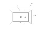
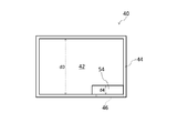
図1は、本発明によるトイレの第1実施形態を示す端面図である。トイレ1は、動物又は人用のトイレであって、本体部10、並びに遮蔽部材22(第1の遮蔽部材)及び遮蔽部材24(第2の遮蔽部材)を備えている。本体部10は、箱状をしており、底面部12(第1の底面部)及び側面部14(第1の側面部)を有している。本体部10は、尿が排泄される便器として機能する。本体部10の材料としては、例えば、ポリプロピレン、ポリエチレン等の樹脂を用いることができる。
FIG. 1 is an end view showing a first embodiment of a toilet according to the present invention. The toilet 1 is a toilet for animals or people, and includes a main body 10, a shielding member 22 (first shielding member), and a shielding member 24 (second shielding member). The main body 10 has a box shape and has a bottom surface portion 12 (first bottom surface portion) and a side surface portion 14 (first side surface portion). The main body 10 functions as a toilet that urine is excreted. As a material of the main body 10, for example, a resin such as polypropylene or polyethylene can be used.
底面部12は、平面視で略矩形状をしている。これに伴い、本体部10には、4つの側面部14が設けられている。本体部10の外形は、略直方体状をしている。
The bottom surface portion 12 has a substantially rectangular shape in plan view. Accordingly, the main body portion 10 is provided with four side surface portions 14. The outer shape of the main body 10 has a substantially rectangular parallelepiped shape.
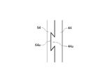
遮蔽部材22は、本体部10内に排泄された尿からの臭気の上昇を遮断する。遮蔽部材22は、板状をしており、側面部14の内面から本体部10の内側に張り出すように設けられている。遮蔽部材22の根元は側面部14の内面上に存在し、遮蔽部材22の先端は本体部10の内部空間中に存在する。遮蔽部材22は、本体部10の内側に向かって下方に傾斜している。遮蔽部材22の上面及び下面の双方が、本体部10の内側に向かって下方に傾斜している。また、遮蔽部材22の一部は、下方に屈曲している。詳細には、遮蔽部材22の先端付近の部分が鉛直方向下向きに屈曲している。なお、遮蔽部材22に孔部は設けられていない。遮蔽部材22の材料としては、例えば、ポリプロピレン、ポリエチレン等の樹脂を用いることができる。
The shielding member 22 blocks an increase in odor from urine excreted in the main body 10. The shielding member 22 has a plate shape and is provided so as to protrude from the inner surface of the side surface portion 14 to the inside of the main body portion 10. The root of the shielding member 22 exists on the inner surface of the side surface portion 14, and the tip of the shielding member 22 exists in the internal space of the main body portion 10. The shielding member 22 is inclined downward toward the inside of the main body 10. Both the upper surface and the lower surface of the shielding member 22 are inclined downward toward the inside of the main body 10. Further, a part of the shielding member 22 is bent downward. Specifically, a portion near the tip of the shielding member 22 is bent downward in the vertical direction. Note that no hole is provided in the shielding member 22. As a material of the shielding member 22, for example, a resin such as polypropylene or polyethylene can be used.
図2は、本体部10を示す平面図である。同図からわかるように、遮蔽部材22は、平面視で、側面部14の内面の全体にわたって設けられている。すなわち、遮蔽部材22は、環状に設けられている。それゆえ、遮蔽部材22で囲まれた部分に開口が生じるが、この開口は、後述する粒状体32の通過を妨げないように充分な大きさを有している。遮蔽部材22の平面視での張出長さd1は、遮蔽部材22の根元を含む平面内における本体部10の最小内寸d0の8分の1以上4分の1以下であることが好ましい。ここで、本体部10の最小内寸とは、本体部10の中心を通る直線と側面部14の内面との2つの交点間の距離の最小値をいう。本実施形態のように本体部10の平面形状が矩形である場合、その最小内寸は、短辺方向の内寸に等しい。
FIG. 2 is a plan view showing the main body 10. As can be seen from the figure, the shielding member 22 is provided over the entire inner surface of the side surface portion 14 in plan view. That is, the shielding member 22 is provided in an annular shape. Therefore, an opening is generated in a portion surrounded by the shielding member 22, and this opening has a sufficient size so as not to prevent passage of a granular material 32 described later. The overhanging length d1 in a plan view of the shielding member 22 is preferably not less than 1/8 and not more than a quarter of the minimum inner dimension d0 of the main body 10 in the plane including the root of the shielding member 22. Here, the minimum internal dimension of the main body 10 refers to the minimum value of the distance between two intersections between the straight line passing through the center of the main body 10 and the inner surface of the side surface 14. When the planar shape of the main body 10 is rectangular as in the present embodiment, the minimum inner dimension is equal to the inner dimension in the short side direction.
図1に戻って、遮蔽部材24は、本体部10内に排泄された尿からの臭気の上昇を遮断する。遮蔽部材24は、板状をしており、側面部14の内面から本体部10の内側に張り出すように設けられている。遮蔽部材24の根元は側面部14の内面上に存在し、遮蔽部材24の先端は本体部10の内部空間中に存在する。遮蔽部材24は、遮蔽部材22と底面部12との間に位置する。すなわち、遮蔽部材24は、遮蔽部材22よりも低い位置(底面部12に近い位置)に配設されている。遮蔽部材24は、本体部10の内側に向かって下方に傾斜している。遮蔽部材24の上面及び下面の双方が、本体部10の内側に向かって下方に傾斜している。また、遮蔽部材24の一部は、下方に屈曲している。詳細には、遮蔽部材24の先端付近の部分が鉛直方向下向きに屈曲している。なお、遮蔽部材24に孔部は設けられていない。遮蔽部材24の材料としては、例えば、ポリプロピレン、ポリエチレン等の樹脂を用いることができる。
Returning to FIG. 1, the shielding member 24 blocks an increase in odor from urine excreted in the main body 10. The shielding member 24 has a plate shape and is provided so as to protrude from the inner surface of the side surface portion 14 to the inside of the main body portion 10. The base of the shielding member 24 exists on the inner surface of the side surface portion 14, and the tip of the shielding member 24 exists in the internal space of the main body portion 10. The shielding member 24 is located between the shielding member 22 and the bottom surface portion 12. That is, the shielding member 24 is disposed at a position lower than the shielding member 22 (position close to the bottom surface portion 12). The shielding member 24 is inclined downward toward the inside of the main body 10. Both the upper surface and the lower surface of the shielding member 24 are inclined downward toward the inside of the main body 10. Further, a part of the shielding member 24 is bent downward. Specifically, a portion near the tip of the shielding member 24 is bent downward in the vertical direction. Note that no hole is provided in the shielding member 24. As a material of the shielding member 24, for example, a resin such as polypropylene or polyethylene can be used.
図3は、本体部10を示す平面図である。ただし、同図においては、遮蔽部材22の図示が省略されている。同図からわかるように、遮蔽部材24は、平面視で、側面部14の内面の全体にわたって設けられている。すなわち、遮蔽部材24は、環状に設けられている。それゆえ、遮蔽部材24で囲まれた部分に開口が生じるが、この開口は、後述する粒状体32の通過を妨げないように充分な大きさを有している。遮蔽部材24の平面視での張出長さd2は、遮蔽部材24の根元を含む平面内における本体部10の最小内寸d0の8分の1以上4分の1以下であることが好ましい。遮蔽部材22の平面視での張出長さd1は、遮蔽部材24の平面視での張出長さd2よりも大きい。遮蔽部材22の少なくとも一部と遮蔽部材24の少なくとも一部とは、平面視で重なり合っている。本実施形態の場合、遮蔽部材22の一部と遮蔽部材24の全体とが、平面視で重なり合っている。
FIG. 3 is a plan view showing the main body 10. However, illustration of the shielding member 22 is omitted in FIG. As can be seen from the figure, the shielding member 24 is provided over the entire inner surface of the side surface portion 14 in plan view. That is, the shielding member 24 is provided in an annular shape. Therefore, an opening is formed in a portion surrounded by the shielding member 24, and this opening has a sufficient size so as not to prevent passage of a granular material 32 described later. The overhanging length d2 in plan view of the shielding member 24 is preferably not less than one-eighth and not more than one-fourth of the minimum inner dimension d0 of the main body 10 in the plane including the root of the shielding member 24. The overhang length d1 of the shielding member 22 in plan view is larger than the overhang length d2 of the shield member 24 in plan view. At least a part of the shielding member 22 and at least a part of the shielding member 24 overlap in plan view. In the case of the present embodiment, a part of the shielding member 22 and the whole shielding member 24 overlap in plan view.
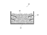
図4は、使用時の本体部10を示す端面図である。トイレ1の使用時、本体部10内には、複数の粒状体32が敷設される。粒状体32は、底面部12上に直接敷設される。粒状体32を敷設する際、本体部10の上部から本体部10内に入れられた粒状体32は、遮蔽部材22で囲まれた部分の開口、及び遮蔽部材24で囲まれた部分の開口を通過して、底面部12まで落下する。このように粒状体32は、遮蔽部材22,24の下方の空間内にも敷設される。粒状体32は、尿を吸収する吸水性のトイレ用敷材である。各粒状体32は、抗菌性を有していることが好ましい。また、各粒状体32は、脱臭性又は消臭性を有していることが好ましい。
FIG. 4 is an end view showing the main body 10 in use. When the toilet 1 is used, a plurality of granular bodies 32 are laid in the main body 10. The granular material 32 is laid directly on the bottom surface portion 12. When laying the granular material 32, the granular material 32 put into the main body 10 from the upper part of the main body 10 has an opening in a portion surrounded by the shielding member 22 and an opening in a portion surrounded by the shielding member 24. It passes and falls to the bottom surface part 12. Thus, the granular material 32 is laid also in the space below the shielding members 22 and 24. The granular material 32 is a water-absorbing toilet floor material that absorbs urine. Each granule 32 preferably has antibacterial properties. Moreover, it is preferable that each granular material 32 has deodorizing property or deodorizing property.
トイレ1の効果を説明する。トイレ1においては、本体部10内に、尿からの臭気の上昇を遮断する遮蔽部材22が設けられている。これにより、本体部10内で尿の臭気の上昇が起こった場合であっても、それを遮断し、本体部10の上部からの臭気漏れを抑制することができる。
Explain the effect of toilet 1. In the toilet 1, a shielding member 22 that blocks an increase in odor from urine is provided in the main body 10. Thereby, even if the urine odor rises in the main body 10, it can be blocked and odor leakage from the upper part of the main body 10 can be suppressed.
さらに、遮蔽部材22と底面部12との間に遮蔽部材24が設けられている。これにより、本体部10内を上昇する臭気を2段階で遮断することができる。このため、本体部10の上部からの臭気漏れを一層効果的に抑制することができる。
Furthermore, a shielding member 24 is provided between the shielding member 22 and the bottom surface portion 12. Thereby, the odor which raises the inside of the main-body part 10 can be interrupted | blocked in two steps. For this reason, the odor leakage from the upper part of the main-body part 10 can be suppressed more effectively.
遮蔽部材22の平面視での張出長さd1は、遮蔽部材24の平面視での張出長さd2よりも大きい。これにより、遮蔽部材24で捕捉しきれなかった臭気を遮蔽部材22で捕捉しやすくなる。
The overhanging length d1 of the shielding member 22 in plan view is larger than the overhanging length d2 of the shielding member 24 in plan view. Thereby, the odor that could not be captured by the shielding member 24 can be easily captured by the shielding member 22.
本体部10内に排泄された尿からの臭気は、水平方向に拡散しながら上昇する。そのため、特に側面部14の内面に沿って、臭気の流れが生じやすい。各遮蔽部材22,24が側面部14の内面から本体部10の内側に張り出すように設けられていることは、側面部14の内面に沿って上昇する臭気を捕捉する上で有利である。
The odor from the urine excreted in the main body 10 rises while diffusing in the horizontal direction. Therefore, the flow of odor tends to occur particularly along the inner surface of the side surface portion 14. It is advantageous to capture the odor rising along the inner surface of the side surface portion 14 so that the shielding members 22 and 24 are provided so as to protrude from the inner surface of the side surface portion 14 to the inside of the main body portion 10.
臭気の遮断効果を高めるには、遮蔽部材22の張出長さd1が大きい方が有利である。他方、張出長さd1が大きすぎると、遮蔽部材22で囲まれた部分の開口に粒状体32が詰まる等の弊害が生じかねない。かかる観点から、遮蔽部材22の張出長さd1は、遮蔽部材22の根元を含む平面内における本体部10の最小内寸d0の8分の1以上4分の1以下であることが好ましい。同様の観点から、遮蔽部材24の張出長さd2は、遮蔽部材24の根元を含む平面内における本体部10の最小内寸d0の8分の1以上4分の1以下であることが好ましい。
In order to enhance the odor blocking effect, it is advantageous that the overhang length d1 of the shielding member 22 is large. On the other hand, if the overhang length d1 is too large, there may be a negative effect such as the granular material 32 being clogged in the opening surrounded by the shielding member 22. From this point of view, it is preferable that the overhanging length d1 of the shielding member 22 is not less than one eighth and not more than one quarter of the minimum inner dimension d0 of the main body 10 in the plane including the root of the shielding member 22. From the same viewpoint, the overhanging length d2 of the shielding member 24 is preferably not less than 1/8 and not more than 1/4 of the minimum inner dimension d0 of the main body 10 in the plane including the root of the shielding member 24. .
遮蔽部材22は、本体部10の内側に向かって下方に傾斜している。このため、遮蔽部材22の下面と側面部14の内面との間の空間に、臭気を閉じ込めることができる。これにより、臭気の遮断効果を高めることができる。また、かかる構成の場合、排泄された尿が遮蔽部材22の上面に達した場合であっても、その尿は傾斜に沿って遮蔽部材22の先端から流れ落ちる。このため、遮蔽部材22の上面に尿が溜まるのを防ぐことができる。
The shielding member 22 is inclined downward toward the inside of the main body 10. For this reason, an odor can be confined in the space between the lower surface of the shielding member 22 and the inner surface of the side surface portion 14. Thereby, the odor blocking effect can be enhanced. In the case of such a configuration, even when excreted urine reaches the upper surface of the shielding member 22, the urine flows down from the tip of the shielding member 22 along the inclination. For this reason, it is possible to prevent urine from accumulating on the upper surface of the shielding member 22.
遮蔽部材22の一部は、下方に屈曲している。このため、遮蔽部材22によって捕捉された臭気が遮蔽部材22の外に逃げにくくなる。これにより、臭気の遮断効果を一層高めることができる。
A part of the shielding member 22 is bent downward. For this reason, it becomes difficult for the odor captured by the shielding member 22 to escape to the outside of the shielding member 22. Thereby, the odor blocking effect can be further enhanced.
遮蔽部材22は、平面視で、側面部14の内面の全体にわたって設けられている。これにより、側面部14の内面に沿った臭気の上昇経路の全体を遮蔽部材22によって塞ぐことができる。
The shielding member 22 is provided over the entire inner surface of the side surface portion 14 in plan view. Thereby, the whole of the odor rising path along the inner surface of the side surface portion 14 can be blocked by the shielding member 22.
遮蔽部材24は、本体部10の内側に向かって下方に傾斜している。このため、遮蔽部材24の下面と側面部14の内面との間の空間に、臭気を閉じ込めることができる。これにより、臭気の遮断効果を高めることができる。また、かかる構成の場合、排泄された尿が遮蔽部材24の上面に達した場合であっても、その尿は傾斜に沿って遮蔽部材24の先端から流れ落ちる。このため、遮蔽部材24の上面に尿が溜まるのを防ぐことができる。
The shielding member 24 is inclined downward toward the inside of the main body 10. For this reason, an odor can be confined in the space between the lower surface of the shielding member 24 and the inner surface of the side surface portion 14. Thereby, the odor blocking effect can be enhanced. In the case of such a configuration, even when excreted urine reaches the upper surface of the shielding member 24, the urine flows down from the tip of the shielding member 24 along the inclination. For this reason, it is possible to prevent urine from accumulating on the upper surface of the shielding member 24.
遮蔽部材24の一部は、下方に屈曲している。このため、遮蔽部材24によって捕捉された臭気が遮蔽部材24の外に逃げにくくなる。これにより、臭気の遮断効果を一層高めることができる。
A part of the shielding member 24 is bent downward. For this reason, it is difficult for the odor captured by the shielding member 24 to escape to the outside of the shielding member 24. Thereby, the odor blocking effect can be further enhanced.
遮蔽部材24は、平面視で、側面部14の内面の全体にわたって設けられている。これにより、側面部14の内面に沿った臭気の上昇経路の全体を遮蔽部材24によって塞ぐことができる。
The shielding member 24 is provided over the entire inner surface of the side surface portion 14 in plan view. Thereby, the whole of the odor rising path along the inner surface of the side surface portion 14 can be blocked by the shielding member 24.
粒状体32は、底面部12上に直接敷設されている。このため、本体部10においては、粒状体32と底面部12との間に仕切部材を設ける必要がない。これにより、本体部10ひいてはトイレ1の構造が複雑化するのを回避することができる。
(第2実施形態)
The granular material 32 is directly laid on the bottom surface portion 12. For this reason, in the main-body part 10, it is not necessary to provide a partition member between the granular material 32 and the bottom face part 12. FIG. Thereby, it can avoid that the structure of the main-body part 10 and hence the toilet 1 becomes complicated.
(Second Embodiment)
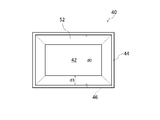
図5は、本発明によるトイレの第2実施形態を示す斜視図である。トイレ2は、動物又は人用のトイレであって、本体部40、遮蔽部材52(第1の遮蔽部材)、遮蔽部材54(第2の遮蔽部材)、及び尿溜容器60を備えている。ただし、遮蔽部材54は、同図においては見えない位置に設けられている(図11参照)。本体部40は、箱状をしており、底面部42(第1の底面部)及び側面部44(第1の側面部)を有している。側面部44には、開口部46(第1の開口部)が設けられている。本体部40は、尿が排泄される便器として機能する。本体部40の材料としては、例えば、ポリプロピレン、ポリエチレン等の樹脂を用いることができる。
FIG. 5 is a perspective view showing a second embodiment of the toilet according to the present invention. The toilet 2 is a toilet for animals or people, and includes a main body 40, a shielding member 52 (first shielding member), a shielding member 54 (second shielding member), and a urine container 60. However, the shielding member 54 is provided at a position that cannot be seen in the figure (see FIG. 11). The main body 40 has a box shape and includes a bottom surface portion 42 (first bottom surface portion) and a side surface portion 44 (first side surface portion). The side surface portion 44 is provided with an opening 46 (first opening). The main body 40 functions as a toilet that urine is excreted. As a material of the main body 40, for example, a resin such as polypropylene or polyethylene can be used.
図6は、本体部40を示す平面図である。同図においては、遮蔽部材52,54の図示が省略されている。図6からわかるように、底面部42は、平面視で略矩形状をしている。これに伴い、本体部40には、4つの側面部44が設けられている。本体部40の外形は、略直方体状をしている。
FIG. 6 is a plan view showing the main body 40. In the figure, illustration of the shielding members 52 and 54 is omitted. As can be seen from FIG. 6, the bottom surface portion 42 has a substantially rectangular shape in plan view. Accordingly, the main body portion 40 is provided with four side surface portions 44. The outer shape of the main body 40 has a substantially rectangular parallelepiped shape.
図7、図8及び図9は、それぞれ、図6のVII-VII線、VIII-VIII線及びIX-IX線に沿った端面図である。これらの図からわかるように、底面部42は、本体部40に排泄された尿が開口部46まで流れるように傾斜している。底面部42は、開口部46の底面に連続している。本実施形態においては、底面部42の全体が傾斜している。底面部42は、連続する複数の平面42a,42b,42cからなる。平面42aは、平面42cに向かって下方に傾斜している。平面42bも、平面42cに向かって下方に傾斜している。また、平面42cは、開口部46に向かって下方に傾斜している。
7, 8, and 9 are end views taken along lines VII-VII, VIII-VIII, and IX-IX of FIG. 6, respectively. As can be seen from these drawings, the bottom surface portion 42 is inclined so that urine excreted in the main body portion 40 flows to the opening 46. The bottom surface portion 42 is continuous with the bottom surface of the opening 46. In the present embodiment, the entire bottom surface portion 42 is inclined. The bottom surface portion 42 includes a plurality of continuous flat surfaces 42a, 42b, and 42c. The plane 42a is inclined downward toward the plane 42c. The plane 42b is also inclined downward toward the plane 42c. Further, the plane 42 c is inclined downward toward the opening 46.
図5に戻って、開口部46は、4つの側面部44のうちの1つに設けられている。開口部46は、横長の形状をしている。開口部46の縦の長さ(側面部44の上下方向についての長さ)は、例えば、3mm以上10mm以下である。開口部46の横の長さ(開口部46が設けられた側面部44の左右方向についての長さ)は、例えば、30mm以上100mm以下である。図6に示すように、開口部46の横の長さw1は、開口部46が設けられた側面部44の横幅(内寸)w2よりも小さい。開口部46の横の長さw1は、側面部44の横幅w2の3分の1以下であることが好ましい。
Returning to FIG. 5, the opening 46 is provided in one of the four side portions 44. The opening 46 has a horizontally long shape. The vertical length of the opening 46 (the length of the side surface 44 in the vertical direction) is, for example, 3 mm or more and 10 mm or less. The horizontal length of the opening 46 (the length in the left-right direction of the side surface 44 provided with the opening 46) is, for example, 30 mm or more and 100 mm or less. As shown in FIG. 6, the lateral length w1 of the opening 46 is smaller than the lateral width (inner dimension) w2 of the side surface 44 where the opening 46 is provided. The lateral length w1 of the opening 46 is preferably equal to or less than one third of the lateral width w2 of the side surface portion 44.
本体部40が載置される床面を基準としたとき、開口部46の下端の高さh1(図5参照)は、30mm以上であることが好ましい。高さh1は、側面部44の下端から開口部46の下端までの距離に等しい。本実施形態において開口部46は、側面部44の端部に位置している。すなわち、開口部46が設けられた側面部44と隣り合う側面部44の内面と同一平面上に、開口部46の側端の一方が存在している。また、図8からわかるように、開口部46の底面は、本体部40の外側に向かって下方に傾斜している。換言すると、開口部46の底面は、側面部44の内面から外面に向かって下方に傾斜している。開口部46は、本体部40内に排泄された尿を本体部40の外に排出する部分である。この開口部46は、尿を通過させるが、後述する粒状体34は通過させない。
The height h1 (see FIG. 5) of the lower end of the opening 46 is preferably 30 mm or more when the floor surface on which the main body 40 is placed is used as a reference. The height h1 is equal to the distance from the lower end of the side surface portion 44 to the lower end of the opening 46. In the present embodiment, the opening 46 is located at the end of the side part 44. That is, one of the side edges of the opening 46 exists on the same plane as the inner surface of the side part 44 adjacent to the side part 44 provided with the opening 46. Further, as can be seen from FIG. 8, the bottom surface of the opening 46 is inclined downward toward the outside of the main body 40. In other words, the bottom surface of the opening 46 is inclined downward from the inner surface of the side surface portion 44 toward the outer surface. The opening 46 is a part for discharging the urine excreted in the main body 40 to the outside of the main body 40. The opening 46 allows urine to pass through, but does not allow passage of granular material 34 described later.
遮蔽部材52は、本体部40内に排泄された尿からの臭気の上昇を遮断する。遮蔽部材52は、板状をしており、側面部44の内面から本体部40の内側に張り出すように設けられている。遮蔽部材52の根元は側面部44の内面上に存在し、遮蔽部材52の先端は本体部40の内部空間中に存在する。遮蔽部材52は、本体部40の内側に向かって下方に傾斜している。遮蔽部材52の上面及び下面の双方が、本体部40の内側に向かって下方に傾斜している。また、遮蔽部材52の一部は、下方に屈曲している。詳細には、遮蔽部材52の先端付近の部分が鉛直方向下向きに屈曲している。なお、遮蔽部材52に孔部は設けられていない。遮蔽部材52の材料としては、例えば、ポリプロピレン、ポリエチレン等の樹脂を用いることができる。
The shielding member 52 blocks an increase in odor from urine excreted in the main body 40. The shielding member 52 has a plate shape and is provided so as to protrude from the inner surface of the side surface portion 44 to the inside of the main body portion 40. The root of the shielding member 52 exists on the inner surface of the side surface portion 44, and the tip of the shielding member 52 exists in the internal space of the main body portion 40. The shielding member 52 is inclined downward toward the inside of the main body 40. Both the upper surface and the lower surface of the shielding member 52 are inclined downward toward the inside of the main body 40. A part of the shielding member 52 is bent downward. Specifically, a portion near the tip of the shielding member 52 is bent downward in the vertical direction. The shielding member 52 is not provided with a hole. As a material of the shielding member 52, for example, a resin such as polypropylene or polyethylene can be used.
図10は、本体部40を示す平面図である。同図からわかるように、遮蔽部材52は、平面視で、側面部44の内面の全体にわたって設けられている。すなわち、遮蔽部材52は、環状に設けられている。それゆえ、遮蔽部材52で囲まれた部分に開口が生じるが、この開口は、後述する粒状体34の通過を妨げないように充分な大きさを有している。遮蔽部材52の平面視での張出長さd3は、遮蔽部材52の根元を含む平面内における本体部40の最小内寸d0の8分の1以上4分の1以下であることが好ましい。
FIG. 10 is a plan view showing the main body 40. As can be seen from the figure, the shielding member 52 is provided over the entire inner surface of the side surface portion 44 in plan view. That is, the shielding member 52 is provided in an annular shape. Therefore, an opening is formed in a portion surrounded by the shielding member 52, but this opening has a sufficient size so as not to prevent passage of a granular material 34 described later. The overhanging length d3 of the shielding member 52 in plan view is preferably not less than 1/8 and not more than 1/4 of the minimum inner dimension d0 of the main body 40 in the plane including the root of the shielding member 52.
遮蔽部材54は、本体部40内に排泄された尿からの臭気の上昇を遮断する。遮蔽部材54は、図8からわかるように、板状をしており、側面部44の内面から本体部40の内側に張り出すように設けられている。遮蔽部材54の根元は側面部44の内面上に存在し、遮蔽部材54の先端は本体部40の内部空間中に存在する。遮蔽部材54は、遮蔽部材52と底面部42との間に位置する。すなわち、遮蔽部材54は、遮蔽部材52よりも低い位置(底面部42に近い位置)に配設されている。遮蔽部材54は、本体部40の内側に向かって下方に傾斜している。遮蔽部材54の上面及び下面の双方が、本体部40の内側に向かって下方に傾斜している。また、遮蔽部材54の一部は、下方に屈曲している。詳細には、遮蔽部材54の先端付近の部分が鉛直方向下向きに屈曲している。なお、遮蔽部材54に孔部は設けられていない。遮蔽部材54の材料としては、例えば、ポリプロピレン、ポリエチレン等の樹脂を用いることができる。
The shielding member 54 blocks an increase in odor from urine excreted in the main body 40. As can be seen from FIG. 8, the shielding member 54 has a plate shape and is provided so as to protrude from the inner surface of the side surface portion 44 to the inside of the main body portion 40. The root of the shielding member 54 exists on the inner surface of the side surface portion 44, and the tip of the shielding member 54 exists in the internal space of the main body portion 40. The shielding member 54 is located between the shielding member 52 and the bottom surface portion 42. That is, the shielding member 54 is disposed at a position lower than the shielding member 52 (position close to the bottom surface portion 42). The shielding member 54 is inclined downward toward the inside of the main body 40. Both the upper surface and the lower surface of the shielding member 54 are inclined downward toward the inside of the main body 40. Further, a part of the shielding member 54 is bent downward. Specifically, a portion near the tip of the shielding member 54 is bent downward in the vertical direction. The shielding member 54 is not provided with a hole. As a material of the shielding member 54, for example, a resin such as polypropylene or polyethylene can be used.
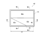
図11は、本体部40を示す平面図である。ただし、同図においては、遮蔽部材52の図示が省略されている。同図からわかるように、遮蔽部材54は、平面視で、側面部44の内面の一部分(開口部46が設けられた領域を含む部分)にのみ設けられている。遮蔽部材54の平面視での張出長さd4は、遮蔽部材54の根元を含む平面内における本体部40の最小内寸d0の8分の1以上4分の1以下であることが好ましい。遮蔽部材52の平面視での張出長さd3は、遮蔽部材54の平面視での張出長さd4よりも大きい。遮蔽部材52の少なくとも一部と遮蔽部材54の少なくとも一部とは、平面視で重なり合っている。本実施形態の場合、遮蔽部材52の一部と遮蔽部材54の全体とが、平面視で重なり合っている。
FIG. 11 is a plan view showing the main body 40. However, the illustration of the shielding member 52 is omitted in FIG. As can be seen from the figure, the shielding member 54 is provided only on a part of the inner surface of the side surface portion 44 (a portion including the region where the opening 46 is provided) in plan view. The overhanging length d4 in a plan view of the shielding member 54 is preferably not less than 1/8 and not more than a quarter of the minimum inner dimension d0 of the main body 40 in a plane including the root of the shielding member 54. The overhanging length d3 of the shielding member 52 in plan view is larger than the overhanging length d4 of the shielding member 54 in plan view. At least a part of the shielding member 52 and at least a part of the shielding member 54 overlap in a plan view. In the case of the present embodiment, a part of the shielding member 52 and the whole shielding member 54 overlap each other in plan view.
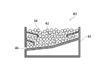
図12は、使用時の本体部40を示す端面図である。同図は、図8と同様の端面を示している。図12に示すように、トイレ2の使用時、本体部40内には、複数の粒状体34が敷設される。粒状体34は、底面部42上に直接敷設される。粒状体34を敷設する際、本体部40の上部から本体部40内に入れられた粒状体34は、遮蔽部材52で囲まれた部分の開口を通過して、底面部42まで落下する。このように粒状体34は、遮蔽部材52,54の下方の空間内にも敷設される。これらの粒状体34は、尿を透過させる透水性のトイレ用敷材である。すなわち、各粒状体34は、尿を全く吸収しないか、殆ど吸収しない性質を有している。各粒状体34は、抗菌性を有していることが好ましい。また、各粒状体34は、脱臭性又は消臭性を有していることが好ましい。粒状体34としては、例えば、非吸水性又は低吸水性の公知のトイレ用敷材を用いることができる。
FIG. 12 is an end view showing the main body 40 in use. This figure shows the same end face as FIG. As shown in FIG. 12, a plurality of granular bodies 34 are laid in the main body 40 when the toilet 2 is used. The granular material 34 is directly laid on the bottom surface portion 42. When laying the granular material 34, the granular material 34 put into the main body 40 from the upper part of the main body 40 passes through the opening of the portion surrounded by the shielding member 52 and falls to the bottom surface 42. Thus, the granular material 34 is also laid in the space below the shielding members 52 and 54. These granular materials 34 are water-permeable toilet floor materials that allow urine to pass therethrough. That is, each granular material 34 has the property of not absorbing urine at all or hardly absorbing. Each granular material 34 preferably has antibacterial properties. Moreover, it is preferable that each granular material 34 has deodorizing property or deodorizing property. As the granular material 34, for example, a known toilet flooring material having no water absorption or low water absorption can be used.
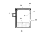
図5に戻って、トイレ2には、尿溜容器60が設置される。尿溜容器60は、開口部46を通過した尿を溜める容器である。尿溜容器60は、箱状をしており、底面部62(第2の底面部)及び側面部64(第2の側面部)を有している。底面部62は、平面視で略矩形状をしている。これに伴い、尿溜容器60には、4つの側面部64が設けられている。尿溜容器60の外形は、本体部40の外形と同様、略直方体状をしている。ただし、尿溜容器60の体積は、本体部40の体積よりも小さい。また、底面部62は、底面部42と異なり、傾斜していない。
Returning to FIG. 5, a urine container 60 is installed in the toilet 2. The urine storage container 60 is a container for storing the urine that has passed through the opening 46. The urine container 60 has a box shape and includes a bottom surface portion 62 (second bottom surface portion) and a side surface portion 64 (second side surface portion). The bottom surface portion 62 has a substantially rectangular shape in plan view. Accordingly, the urine container 60 is provided with four side portions 64. The outer shape of the urine container 60 is substantially rectangular parallelepiped like the outer shape of the main body 40. However, the volume of the urine container 60 is smaller than the volume of the main body 40. Further, unlike the bottom surface portion 42, the bottom surface portion 62 is not inclined.
側面部64には、開口部66(第2の開口部)が設けられている。開口部66は、開口部46から排出された尿を尿溜容器60内に流入させるように設けられている。開口部66は、4つの側面部64のうちの1つに設けられている。開口部66は、開口部46と略同一の形状及び大きさをしている。厳密には、側面部44の外面における開口部46の形状及び大きさと、側面部64の外面における開口部66の形状及び大きさとが略一致する。さらに、尿溜容器60は、底面部62及び側面部64で囲まれた空間を上方から覆う蓋部68を有している。蓋部68は、開閉可能に設けられている。トイレ2の使用時、蓋部68は閉じられる。蓋部68が閉じられた状態では、尿溜容器60内は、開口部66を除いて密閉される。尿溜容器60の材料としては、例えば、ポリプロピレン、ポリエチレン等の樹脂を用いることができる。
The side surface portion 64 is provided with an opening 66 (second opening). The opening 66 is provided so that urine discharged from the opening 46 flows into the urine container 60. The opening 66 is provided in one of the four side surfaces 64. The opening 66 has substantially the same shape and size as the opening 46. Strictly speaking, the shape and size of the opening 46 on the outer surface of the side surface portion 44 substantially match the shape and size of the opening 66 on the outer surface of the side surface portion 64. Furthermore, the urine container 60 has a lid portion 68 that covers the space surrounded by the bottom surface portion 62 and the side surface portion 64 from above. The cover part 68 is provided so that opening and closing is possible. When the toilet 2 is used, the lid 68 is closed. In the state where the lid 68 is closed, the inside of the urine container 60 is sealed except for the opening 66. As a material of the urine container 60, for example, a resin such as polypropylene or polyethylene can be used.
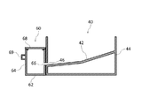
図13は、本体部40の横に尿溜容器60が設置された状態を示す端面図である。同図に示すように、トイレ2の使用時、尿溜容器60は、開口部46が設けられた側面部44に対して略隙間なく接した状態で設置される。このとき、尿溜容器60の開口部66は、本体部40の開口部46に重なる。本実施形態において開口部46と開口部66とは、互いに完全に重なり合う。すなわち、開口部46の全体が開口部66に重なるとともに、開口部66の全体も開口部46に重なる。尿溜容器60は、本体部40に対して固定されている。側面部64の上端は、開口部46の上端よりも高い位置にある。開口部66の底面は、尿溜容器60の内側に向かって下方に傾斜している。換言すると、開口部66の底面は、側面部64の外面から内面に向かって下方に傾斜している。また、尿溜容器60には、把手69が設けられている。具体的には、把手69は、開口部66が設けられた側面部64と対向する側面部64に設けられている。
FIG. 13 is an end view showing a state in which the urine container 60 is installed beside the main body 40. As shown in the figure, when the toilet 2 is used, the urine container 60 is installed in a state in which the urine storage container 60 is in contact with the side surface portion 44 provided with the opening 46 with substantially no gap. At this time, the opening 66 of the urine container 60 overlaps the opening 46 of the main body 40. In the present embodiment, the opening 46 and the opening 66 completely overlap each other. That is, the entire opening 46 overlaps the opening 66 and the entire opening 66 also overlaps the opening 46. The urine container 60 is fixed to the main body 40. The upper end of the side surface portion 64 is located higher than the upper end of the opening 46. The bottom surface of the opening 66 is inclined downward toward the inside of the urine container 60. In other words, the bottom surface of the opening 66 is inclined downward from the outer surface of the side surface portion 64 toward the inner surface. The urine container 60 is provided with a handle 69. Specifically, the handle 69 is provided on the side surface portion 64 facing the side surface portion 64 provided with the opening 66.
尿溜容器60は、本体部40に対して着脱可能に固定されている。ここで、着脱可能とは、本体部40及び尿溜容器60を損傷することなく、本体部40に対する尿溜容器60の取付け及び取外しを容易に行えるということである。
The urine container 60 is detachably fixed to the main body 40. Here, detachable means that the urine container 60 can be easily attached to and detached from the main body 40 without damaging the main body 40 and the urine container 60.
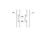
かかる構成は、例えば図14に示すように、側面部44に突条44aを設けるとともに、側面部64に溝64aを設けることにより実現することができる。同図は、側面部44及び側面部64を上から見た図である。突条44aは、側面部44における側面部64に対向する部分に設けられている。突条44aは、側面部44から遠ざかるにつれて幅が広くなるテーパ状の断面形状を有しており、側面部44の上下方向(図14において紙面に垂直な方向)に延在している。他方、溝64aは、側面部64における側面部44に対向する部分に設けられている。溝64aは、側面部64の内部に近づくにつれて幅が広くなるテーパ状の断面形状を有しており、側面部64の上下方向に延在している。溝64aの断面は、突条44aの断面と略同一の形状及び大きさを有している。
For example, as shown in FIG. 14, such a configuration can be realized by providing a protrusion 44 a on the side surface portion 44 and providing a groove 64 a on the side surface portion 64. The figure is a view of the side surface portion 44 and the side surface portion 64 as viewed from above. The protrusion 44 a is provided in a portion of the side surface portion 44 that faces the side surface portion 64. The protrusion 44a has a tapered cross-sectional shape that increases in width as the distance from the side surface portion 44 increases, and extends in the vertical direction of the side surface portion 44 (a direction perpendicular to the paper surface in FIG. 14). On the other hand, the groove 64 a is provided in a portion of the side surface portion 64 that faces the side surface portion 44. The groove 64 a has a tapered cross-sectional shape that increases in width toward the inside of the side surface portion 64, and extends in the vertical direction of the side surface portion 64. The cross section of the groove 64a has substantially the same shape and size as the cross section of the protrusion 44a.
本体部40に対して尿溜容器60を上下方向にスライドさせて、図15に示すように突条44aと溝64aとを嵌合させることにより、本体部40に尿溜容器60を取り付けて固定することができる。また、本体部40に対して尿溜容器60を上下方向にスライドさせて、突条44aと溝64aとの嵌合を解くことにより、本体部40から尿溜容器60を取り外すことができる。
The urine container 60 is slid in the vertical direction with respect to the main body 40 and the ridge 44a and the groove 64a are fitted as shown in FIG. can do. Further, the urine storage container 60 can be removed from the main body 40 by sliding the urine storage container 60 in the vertical direction with respect to the main body 40 and releasing the fitting between the protrusion 44a and the groove 64a.
図16は、使用時の尿溜容器60を示す端面図である。同図に示すように、トイレ2の使用時、尿溜容器60内には、尿を吸収する吸水材70が配設される。吸水材70は、例えば、植物性材料の粉砕物と吸水性ポリマーとの混合物(粉体)からなる。その場合、植物性材料としては、例えば、茶類(茶葉、茶殻等)、又はコーヒー類(コーヒー豆、インスタントコーヒー、コーヒー滓等)を用いることができる。植物性材料としては、各種植物の枝、葉(例えば笹の葉)又は花を用いてもよい。なお、吸水材70は、吸水性ポリマーのみからなっていてもよい。また、吸水材70としては、粒状のトイレ用敷材(例えば上記粉体を造粒したもの)、又はシート状のトイレ用敷材(吸水性シート)を用いてもよい。
FIG. 16 is an end view showing the urine container 60 in use. As shown in the figure, a water absorbing material 70 that absorbs urine is disposed in the urine storage container 60 when the toilet 2 is used. The water absorbing material 70 is made of, for example, a mixture (powder) of a pulverized vegetable material and a water absorbing polymer. In this case, as the plant material, for example, teas (tea leaves, tea husks, etc.) or coffees (coffee beans, instant coffee, coffee cake, etc.) can be used. As plant materials, branches, leaves (for example, bamboo leaves) or flowers of various plants may be used. In addition, the water absorbing material 70 may consist only of a water absorbing polymer. Further, as the water absorbing material 70, a granular toilet flooring material (for example, granulated powder) or a sheet-like toilet flooring material (water absorbent sheet) may be used.
尿溜容器60には、収容袋80が設けられている。収容袋80は、吸水材70を収容する袋であり、尿溜容器60内に設置される。収容袋80は、底面部62の上面及び側面部64の内面の略全体を覆っている。収容袋80は、側面部64の上端で折り返されている。この折り返された部分が側面部64と蓋部68とで挟まれることにより、収容袋80が尿溜容器60に固定されている。
The urine container 60 is provided with a storage bag 80. The storage bag 80 is a bag for storing the water absorbing material 70 and is installed in the urine container 60. The storage bag 80 covers substantially the entire upper surface of the bottom surface portion 62 and the inner surface of the side surface portion 64. The storage bag 80 is folded at the upper end of the side surface portion 64. The folded bag is sandwiched between the side surface portion 64 and the lid portion 68, so that the storage bag 80 is fixed to the urine reservoir 60.
図17は、収容袋80を示す正面図である。収容袋80には、穴部82が設けられている。穴部82は、尿を通過させる一方で、吸水材70は通過させない。本実施形態においては、収容袋80の少なくとも一部分(開口部66に重なる領域を含む部分)が網状をしており、当該部分の網目が穴部82を構成している。図17においては、収容袋80の全体が網状をしている例を示している。収容袋80の材料としては、例えば、ポリエチレン、ポリ塩化ビニル、ナイロン等を用いることができる。
FIG. 17 is a front view showing the containing bag 80. The accommodation bag 80 is provided with a hole 82. The hole portion 82 allows urine to pass therethrough but does not allow the water absorbing material 70 to pass therethrough. In the present embodiment, at least a part of the accommodation bag 80 (a part including a region overlapping the opening 66) has a net shape, and the mesh of the part constitutes the hole part 82. FIG. 17 shows an example in which the entire storage bag 80 has a net shape. As a material of the storage bag 80, for example, polyethylene, polyvinyl chloride, nylon or the like can be used.
トイレ2の効果を説明する。トイレ2においては、本体部40内に、尿からの臭気の上昇を遮断する遮蔽部材52が設けられている。これにより、本体部40内で尿の臭気の上昇が起こった場合であっても、それを遮断し、本体部40の上部からの臭気漏れを抑制することができる。
Explain the effect of toilet 2. In the toilet 2, a shielding member 52 that blocks an increase in odor from urine is provided in the main body 40. Thereby, even if the urine odor rises in the main body 40, it can be blocked and odor leakage from the upper part of the main body 40 can be suppressed.
さらに、遮蔽部材52と底面部42との間に遮蔽部材54が設けられている。これにより、本体部40内を上昇する臭気を2段階で遮断することができる。このため、本体部40の上部からの臭気漏れを一層効果的に抑制することができる。
Furthermore, a shielding member 54 is provided between the shielding member 52 and the bottom surface portion 42. Thereby, the odor which raises the inside of the main-body part 40 can be interrupted | blocked in two steps. For this reason, the odor leakage from the upper part of the main-body part 40 can be suppressed more effectively.
遮蔽部材52の平面視での張出長さd3は、遮蔽部材54の平面視での張出長さd4よりも大きい。これにより、遮蔽部材54で捕捉しきれなかった臭気を遮蔽部材52で捕捉しやすくなる。
The overhanging length d3 of the shielding member 52 in plan view is larger than the overhanging length d4 of the shielding member 54 in plan view. As a result, the odor that could not be captured by the shielding member 54 can be easily captured by the shielding member 52.
本体部40内に排泄された尿からの臭気は、水平方向に拡散しながら上昇する。そのため、特に側面部44の内面に沿って、臭気の流れが生じやすい。各遮蔽部材52,54が側面部44の内面から本体部40の内側に張り出すように設けられていることは、側面部44の内面に沿って上昇する臭気を捕捉する上で有利である。
The odor from the urine excreted in the main body 40 rises while diffusing in the horizontal direction. Therefore, the flow of odor tends to occur particularly along the inner surface of the side surface portion 44. It is advantageous to capture the odor rising along the inner surface of the side surface portion 44 so that the shielding members 52 and 54 are provided so as to protrude from the inner surface of the side surface portion 44 to the inside of the main body portion 40.
臭気の遮断効果を高めるには、遮蔽部材52の張出長さd3が大きい方が有利である。他方、張出長さd3が大きすぎると、遮蔽部材52で囲まれた部分の開口に粒状体34が詰まる等の弊害が生じかねない。かかる観点から、遮蔽部材52の張出長さd3は、遮蔽部材52の根元を含む平面内における本体部40の最小内寸d0の8分の1以上4分の1以下であることが好ましい。同様の観点から、遮蔽部材54の張出長さd4は、遮蔽部材54の根元を含む平面内における本体部40の最小内寸d0の8分の1以上4分の1以下であることが好ましい。
In order to enhance the odor blocking effect, it is advantageous that the overhang length d3 of the shielding member 52 is large. On the other hand, if the overhang length d3 is too large, there may be a negative effect such as clogging of the granular material 34 in the opening surrounded by the shielding member 52. From this point of view, the overhanging length d3 of the shielding member 52 is preferably not less than one eighth and not more than one quarter of the minimum inner dimension d0 of the main body 40 in the plane including the root of the shielding member 52. From the same viewpoint, the overhanging length d4 of the shielding member 54 is preferably not less than one eighth and not more than one quarter of the minimum inner dimension d0 of the main body 40 in a plane including the root of the shielding member 54. .
遮蔽部材52は、本体部40の内側に向かって下方に傾斜している。このため、遮蔽部材52の下面と側面部44の内面との間の空間に、臭気を閉じ込めることができる。これにより、臭気の遮断効果を高めることができる。また、かかる構成の場合、排泄された尿が遮蔽部材52の上面に達した場合であっても、その尿は傾斜に沿って遮蔽部材52の先端から流れ落ちる。このため、遮蔽部材52の上面に尿が溜まるのを防ぐことができる。
The shielding member 52 is inclined downward toward the inside of the main body 40. For this reason, an odor can be confined in the space between the lower surface of the shielding member 52 and the inner surface of the side surface portion 44. Thereby, the odor blocking effect can be enhanced. In the case of such a configuration, even if the excreted urine reaches the upper surface of the shielding member 52, the urine flows down from the tip of the shielding member 52 along the inclination. For this reason, it is possible to prevent urine from accumulating on the upper surface of the shielding member 52.
遮蔽部材52の一部は、下方に屈曲している。このため、遮蔽部材52によって捕捉された臭気が遮蔽部材52の外に逃げにくくなる。これにより、臭気の遮断効果を一層高めることができる。
A part of the shielding member 52 is bent downward. For this reason, the odor captured by the shielding member 52 is unlikely to escape from the shielding member 52. Thereby, the odor blocking effect can be further enhanced.
遮蔽部材52は、平面視で、側面部44の内面の全体にわたって設けられている。これにより、側面部44の内面に沿った臭気の上昇経路の全体を遮蔽部材52によって塞ぐことができる。
The shielding member 52 is provided over the entire inner surface of the side surface portion 44 in plan view. Thereby, the whole of the odor rising path along the inner surface of the side surface portion 44 can be blocked by the shielding member 52.
遮蔽部材54は、本体部40の内側に向かって下方に傾斜している。このため、遮蔽部材54の下面と側面部44の内面との間の空間に、臭気を閉じ込めることができる。これにより、臭気の遮断効果を高めることができる。また、かかる構成の場合、排泄された尿が遮蔽部材54の上面に達した場合であっても、その尿は傾斜に沿って遮蔽部材54の先端から流れ落ちる。このため、遮蔽部材54の上面に尿が溜まるのを防ぐことができる。
The shielding member 54 is inclined downward toward the inside of the main body 40. For this reason, the odor can be confined in the space between the lower surface of the shielding member 54 and the inner surface of the side surface portion 44. Thereby, the odor blocking effect can be enhanced. Further, in such a configuration, even when excreted urine reaches the upper surface of the shielding member 54, the urine flows down from the tip of the shielding member 54 along the inclination. For this reason, it is possible to prevent urine from accumulating on the upper surface of the shielding member 54.
遮蔽部材54の一部は、下方に屈曲している。このため、遮蔽部材54によって捕捉された臭気が遮蔽部材54の外に逃げにくくなる。これにより、臭気の遮断効果を一層高めることができる。
A part of the shielding member 54 is bent downward. For this reason, the odor captured by the shielding member 54 is difficult to escape to the outside of the shielding member 54. Thereby, the odor blocking effect can be further enhanced.
遮蔽部材54は、平面視で、側面部44の内面の一部分にのみ設けられている。これにより、本実施形態のように底面部42が傾斜している場合に、底面部42の最高点よりも低い位置に遮蔽部材54を配設することが可能となり、設計自由度が高まる。特に遮蔽部材54が設けられた上記部分は、開口部46が設けられた領域を含んでいる。このため、開口部46の入口付近は、上方が遮蔽部材54によって覆われている。これにより、本体部40の外に排出された尿からの臭気が開口部46を通じて本体部40内に流れ込んできた場合であっても、当該臭気の上昇を効果的に遮断することができる。
The shielding member 54 is provided only on a part of the inner surface of the side surface portion 44 in plan view. Accordingly, when the bottom surface portion 42 is inclined as in the present embodiment, the shielding member 54 can be disposed at a position lower than the highest point of the bottom surface portion 42, and the degree of freedom in design is increased. In particular, the portion where the shielding member 54 is provided includes a region where the opening 46 is provided. For this reason, the upper part of the vicinity of the entrance of the opening 46 is covered with the shielding member 54. Thereby, even if the odor from the urine discharged | emitted out of the main-body part 40 flows in in the main-body part 40 through the opening part 46, the raise of the said odor can be interrupted | blocked effectively.
本体部40の側面部44に開口部46が設けられている。そして、本体部40の底面部42は、尿が開口部46まで流れるように傾斜している。このため、本体部40内に排泄された尿は、粒状体34どうしの間を通過した後、底面部42上を流れて、開口部46に達する。開口部46に達した尿は、開口部46を通過して、本体部40の外に排出される。かかる構成は、尿を本体部40に残留させないため、本体部40の上部からの臭気漏れを抑制する上で有利である。
An opening 46 is provided in the side surface 44 of the main body 40. The bottom surface 42 of the main body 40 is inclined so that urine flows to the opening 46. For this reason, the urine excreted in the main body portion 40 passes between the particulate bodies 34, then flows on the bottom surface portion 42 and reaches the opening 46. The urine that has reached the opening 46 passes through the opening 46 and is discharged out of the main body 40. Such a configuration is advantageous in suppressing odor leakage from the upper portion of the main body 40 because urine does not remain in the main body 40.
底面部42は、全体が傾斜している。これにより、排泄された尿が底面部42上のどの位置に落ちても、当該尿を開口部46まで確実に導くことができる。
The entire bottom surface 42 is inclined. Thereby, no matter where the excreted urine falls on the bottom surface portion 42, the urine can be reliably guided to the opening 46.
開口部46は、横長の形状をしている。すなわち、開口部46は、横の長さが大きく、縦の長さが小さい。尿のような液体は、横に広がる性質を有する。それゆえ、開口部46の横の長さを大きくすることは、多量の尿を迅速に通過させるのに適している。これにより、多量の尿が排泄された場合であっても、当該尿を開口部46を通じてスムーズに本体部40の外に排出することができる。他方、開口部46の縦の長さを小さくすることは、当該開口部46を粒状体34が通過するのを防ぐ上で有利である。
The opening 46 has a horizontally long shape. That is, the opening 46 has a large horizontal length and a small vertical length. A liquid such as urine has a property of spreading laterally. Therefore, increasing the lateral length of the opening 46 is suitable for rapidly passing a large amount of urine. Thereby, even when a large amount of urine is excreted, the urine can be smoothly discharged out of the main body 40 through the opening 46. On the other hand, reducing the vertical length of the opening 46 is advantageous in preventing the granular material 34 from passing through the opening 46.
開口部46の底面は、本体部40の外側に向かって下方に傾斜している。これにより、本体部40内に排泄された尿を開口部46を通じて本体部40の外に、よりスムーズに排出することができる。
The bottom surface of the opening 46 is inclined downward toward the outside of the main body 40. Thereby, the urine excreted in the main body 40 can be more smoothly discharged out of the main body 40 through the opening 46.
粒状体34は、底面部42上に直接敷設されている。このため、本体部40においては、粒状体34と底面部42との間に仕切部材を設ける必要がない。これにより、本体部40ひいてはトイレ2の構造が複雑化するのを回避することができる。
The granular material 34 is directly laid on the bottom surface portion 42. For this reason, in the main body portion 40, it is not necessary to provide a partition member between the granular material 34 and the bottom surface portion 42. Thereby, it can avoid that the structure of the main-body part 40 and hence the toilet 2 becomes complicated.
トイレ2には、尿溜容器60が設けられている。これにより、開口部46を通じて本体部40の外に排出された尿を容易に処理することができる。
The toilet 2 is provided with a urine container 60. Thereby, the urine discharged | emitted out of the main-body part 40 through the opening part 46 can be processed easily.
尿溜容器60は、開口部46が設けられた側面部44に略隙間なく接した状態で設置される。これにより、本体部40と尿溜容器60との間に尿を移送するための手段を設けることなく、開口部46から排出された尿を尿溜容器60内に直接導くことができる。
The urine container 60 is installed in a state where it is in contact with the side surface portion 44 provided with the opening 46 without any substantial gap. As a result, urine discharged from the opening 46 can be directly guided into the urine container 60 without providing a means for transferring urine between the main body 40 and the urine container 60.
側面部64には、開口部66が設けられている。これにより、簡易な構成で、開口部46から排出された尿を尿溜容器60内に導くことができる。すなわち、開口部46から排出された尿は、開口部46と連続する開口部66を通じて、尿溜容器60内に流入することになる。また、側面部64から尿を尿溜容器60内に取り込めるようになるため、側面部64の高さを大きくすることができる。側面部64の高さを大きくすることは、尿溜容器60の容積を大きくし、より多量の尿を溜められるようになる点で有利である。
The side surface portion 64 is provided with an opening 66. Thereby, the urine discharged | emitted from the opening part 46 can be guide | induced in the urine container 60 with a simple structure. That is, urine discharged from the opening 46 flows into the urine reservoir 60 through the opening 66 continuous with the opening 46. In addition, since urine can be taken into the urine container 60 from the side surface portion 64, the height of the side surface portion 64 can be increased. Increasing the height of the side surface portion 64 is advantageous in that the volume of the urine storage container 60 is increased and a larger amount of urine can be stored.
開口部66の底面は、尿溜容器60の内側に向かって下方に傾斜している。これにより、開口部46から排出された尿を開口部66を通じて尿溜容器60内に、よりスムーズに流入させることができる。
The bottom surface of the opening 66 is inclined downward toward the inside of the urine container 60. As a result, urine discharged from the opening 46 can flow more smoothly into the urine container 60 through the opening 66.
側面部64の上端は、尿溜容器60がトイレ2に設置された状態で、開口部46の上端よりも高い位置にある。これにより、尿溜容器60内に溜った尿から発生した臭気が開口部46を通じて本体部40内に流れ込むのを抑制することができる。
The upper end of the side part 64 is at a position higher than the upper end of the opening 46 in a state where the urine container 60 is installed in the toilet 2. Thereby, the odor generated from the urine collected in the urine container 60 can be prevented from flowing into the main body 40 through the opening 46.
尿溜容器60は、底面部62及び側面部64で囲まれた空間を上方から覆う蓋部68を有している。これにより、尿溜容器60内に溜った尿から発生した臭気が、尿溜容器60の上部から外に漏れるのを防ぐことができる。
The urine container 60 has a lid portion 68 that covers the space surrounded by the bottom surface portion 62 and the side surface portion 64 from above. Thereby, the odor generated from the urine collected in the urine container 60 can be prevented from leaking out from the upper part of the urine container 60.
尿溜容器60は、本体部40に対して着脱可能である。これにより、尿溜容器60に溜った尿の処分や、本体部40及び尿溜容器60の清掃が容易になる。すなわち、本体部40から尿溜容器60を取り外すことにより、尿の処分や清掃を行いやすくなる。
The urine container 60 is detachable from the main body 40. Thereby, disposal of urine collected in the urine container 60 and cleaning of the main body 40 and the urine container 60 are facilitated. That is, by removing the urine container 60 from the main body 40, it becomes easier to dispose of and clean the urine.
尿溜容器60には、把手69が設けられている。これにより、本体部40に対する尿溜容器60の着脱が容易になる。
The urine container 60 is provided with a handle 69. Thereby, the urine storage container 60 can be easily attached to and detached from the main body 40.
尿溜容器60に溜った尿が開口部66を通じて尿溜容器60の外に漏れるのを防ぐには、開口部46(及び開口部66)の位置が高い方が有利である。かかる観点から、開口部46の下端の高さh1(図5参照)は、30mm以上であることが好ましい。
In order to prevent urine collected in the urine container 60 from leaking out of the urine container 60 through the opening 66, it is advantageous that the position of the opening 46 (and the opening 66) is higher. From this viewpoint, the height h1 (see FIG. 5) of the lower end of the opening 46 is preferably 30 mm or more.
トイレ2の使用時、尿溜容器60内には、尿を吸収する吸水材70が配設される。これにより、かかる吸水材70が設けられていない場合に比して、尿が尿溜容器60の外に漏れにくくなる。
When the toilet 2 is used, a water absorbing material 70 that absorbs urine is disposed in the urine storage container 60. Thereby, compared with the case where this water absorbing material 70 is not provided, urine becomes difficult to leak out of the urine container 60.
吸水材70が植物性材料の粉砕物と吸水性ポリマーとの混合物からなる場合、植物性材料の消臭効果により尿の悪臭を緩和することができる。また、吸水性ポリマーの吸水力により、多量の尿を吸収することができる。
When the water-absorbing material 70 is made of a mixture of a pulverized plant material and a water-absorbing polymer, the odor of urine can be mitigated by the deodorizing effect of the plant material. Moreover, a large amount of urine can be absorbed by the water absorbing power of the water absorbing polymer.
植物性材料として茶類又はコーヒー類を用いた場合、特に優れた消臭効果を得ることができる。また、茶殻やコーヒー滓のような廃棄物を用いた場合、廃棄物を有効活用することができる。
When tea or coffee is used as the plant material, a particularly excellent deodorizing effect can be obtained. In addition, when wastes such as tea husks and coffee cakes are used, the wastes can be effectively utilized.
尿溜容器60には、収容袋80が設けられている。これにより、尿を吸収した吸水材70をまとめて収容袋80ごと尿溜容器60から取り出すことができる。したがって、尿溜容器60に溜った尿の処分が一層容易になる。
The urine container 60 is provided with a storage bag 80. Thereby, the water absorbing material 70 which absorbed urine can be taken out from the urine storage container 60 together with the containing bag 80. Therefore, disposal of urine collected in the urine storage container 60 is further facilitated.
収容袋80には、吸水材70を通過させずに尿を通過させる穴部82が設けられている。これにより、吸水材70が収容袋80の外にこぼれるのを防ぎつつ、開口部66を通過した尿を収容袋80内に導くことができる。
The accommodation bag 80 is provided with a hole 82 through which urine can pass without passing through the water absorbing material 70. Thereby, urine that has passed through the opening 66 can be guided into the storage bag 80 while preventing the water absorbing material 70 from spilling out of the storage bag 80.
収容袋80の少なくとも一部分が網状をしており、当該部分の網目が穴部82を構成している。これにより、簡易な構成で、穴部82を有する収容袋80を実現することができる。
At least a part of the storage bag 80 has a net shape, and the mesh of the part constitutes the hole 82. Thereby, the storage bag 80 having the hole 82 can be realized with a simple configuration.
本発明は、上記実施形態に限定されるものではなく、様々な変形が可能である。上記実施形態においては、2つの遮蔽部材が設けられた例を示した。しかし、遮蔽部材は1つだけ設けられてもよい。例えば、第1実施形態の場合であれば遮蔽部材22又は遮蔽部材24の何れか一方のみが設けられてもよく、第2実施形態の場合であれば遮蔽部材52又は遮蔽部材54の何れか一方のみが設けられてもよい。また、3つ以上の遮蔽部材が設けられてもよい。
The present invention is not limited to the above embodiment, and various modifications are possible. In the said embodiment, the example in which the two shielding members were provided was shown. However, only one shielding member may be provided. For example, in the case of the first embodiment, only one of the shielding member 22 or the shielding member 24 may be provided. In the case of the second embodiment, either the shielding member 52 or the shielding member 54 is provided. Only may be provided. Three or more shielding members may be provided.
上記実施形態においては、遮蔽部材22の一部が屈曲した例を示した。しかし、遮蔽部材22の一部を屈曲させることは必須でない。すなわち、遮蔽部材22は、図18に示すように、根元から先端まで同一平面上にあってもよい。遮蔽部材24,52,54についても同様である。
In the above embodiment, an example in which a part of the shielding member 22 is bent is shown. However, it is not essential to bend a part of the shielding member 22. That is, the shielding member 22 may be on the same plane from the root to the tip as shown in FIG. The same applies to the shielding members 24, 52, and 54.
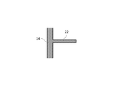
上記実施形態においては、遮蔽部材22が傾斜した例を示した。しかし、遮蔽部材22を傾斜させることは必須でない。すなわち、遮蔽部材22は、図19に示すように、水平に張り出していてもよい。遮蔽部材24,52,54についても同様である。
In the above embodiment, an example in which the shielding member 22 is inclined has been shown. However, it is not essential to incline the shielding member 22. That is, the shielding member 22 may project horizontally as shown in FIG. The same applies to the shielding members 24, 52, and 54.
上記実施形態においては、本体部に仕切部材が設けられていない例を示した。しかし、本体部には、仕切部材が設けられていてもよい。かかる仕切部材上には、尿を透過させる粒状体が敷設される。また、仕切部材には、尿を通過させるが、上記粒状体を通過させない孔部が形成されている。この場合、遮蔽部材は、仕切部材の上方の空間もしくは下方の空間の何れか一方又は双方に配設される。
In the above embodiment, an example in which a partition member is not provided in the main body portion is shown. However, the main body may be provided with a partition member. On the partition member, a granular material that allows urine to pass therethrough is laid. The partition member is formed with a hole that allows urine to pass therethrough but does not allow the granular material to pass therethrough. In this case, the shielding member is disposed in one or both of the space above the partition member and the space below.