WO2017149618A1 - Control device, power generation control device, control method, system, and program - Google Patents
Control device, power generation control device, control method, system, and program Download PDFInfo
- Publication number
- WO2017149618A1 WO2017149618A1 PCT/JP2016/056115 JP2016056115W WO2017149618A1 WO 2017149618 A1 WO2017149618 A1 WO 2017149618A1 JP 2016056115 W JP2016056115 W JP 2016056115W WO 2017149618 A1 WO2017149618 A1 WO 2017149618A1
- Authority
- WO
- WIPO (PCT)
- Prior art keywords
- power generation
- output
- surplus
- power
- control device
- Prior art date
Links
Images


Classifications
-
- H—ELECTRICITY
- H02—GENERATION; CONVERSION OR DISTRIBUTION OF ELECTRIC POWER
- H02J—CIRCUIT ARRANGEMENTS OR SYSTEMS FOR SUPPLYING OR DISTRIBUTING ELECTRIC POWER; SYSTEMS FOR STORING ELECTRIC ENERGY
- H02J3/00—Circuit arrangements for ac mains or ac distribution networks
- H02J3/28—Arrangements for balancing of the load in a network by storage of energy
-
- G—PHYSICS
- G05—CONTROLLING; REGULATING
- G05B—CONTROL OR REGULATING SYSTEMS IN GENERAL; FUNCTIONAL ELEMENTS OF SUCH SYSTEMS; MONITORING OR TESTING ARRANGEMENTS FOR SUCH SYSTEMS OR ELEMENTS
- G05B15/00—Systems controlled by a computer
- G05B15/02—Systems controlled by a computer electric
-
- H—ELECTRICITY
- H02—GENERATION; CONVERSION OR DISTRIBUTION OF ELECTRIC POWER
- H02J—CIRCUIT ARRANGEMENTS OR SYSTEMS FOR SUPPLYING OR DISTRIBUTING ELECTRIC POWER; SYSTEMS FOR STORING ELECTRIC ENERGY
- H02J3/00—Circuit arrangements for ac mains or ac distribution networks
- H02J3/003—Load forecast, e.g. methods or systems for forecasting future load demand
-
- H—ELECTRICITY
- H02—GENERATION; CONVERSION OR DISTRIBUTION OF ELECTRIC POWER
- H02J—CIRCUIT ARRANGEMENTS OR SYSTEMS FOR SUPPLYING OR DISTRIBUTING ELECTRIC POWER; SYSTEMS FOR STORING ELECTRIC ENERGY
- H02J3/00—Circuit arrangements for ac mains or ac distribution networks
- H02J3/38—Arrangements for parallely feeding a single network by two or more generators, converters or transformers
- H02J3/381—Dispersed generators
-
- H—ELECTRICITY
- H02—GENERATION; CONVERSION OR DISTRIBUTION OF ELECTRIC POWER
- H02J—CIRCUIT ARRANGEMENTS OR SYSTEMS FOR SUPPLYING OR DISTRIBUTING ELECTRIC POWER; SYSTEMS FOR STORING ELECTRIC ENERGY
- H02J3/00—Circuit arrangements for ac mains or ac distribution networks
- H02J3/38—Arrangements for parallely feeding a single network by two or more generators, converters or transformers
- H02J3/46—Controlling of the sharing of output between the generators, converters, or transformers
-
- H—ELECTRICITY
- H02—GENERATION; CONVERSION OR DISTRIBUTION OF ELECTRIC POWER
- H02J—CIRCUIT ARRANGEMENTS OR SYSTEMS FOR SUPPLYING OR DISTRIBUTING ELECTRIC POWER; SYSTEMS FOR STORING ELECTRIC ENERGY
- H02J7/00—Circuit arrangements for charging or depolarising batteries or for supplying loads from batteries
- H02J7/0013—Circuit arrangements for charging or depolarising batteries or for supplying loads from batteries acting upon several batteries simultaneously or sequentially
-
- H—ELECTRICITY
- H02—GENERATION; CONVERSION OR DISTRIBUTION OF ELECTRIC POWER
- H02J—CIRCUIT ARRANGEMENTS OR SYSTEMS FOR SUPPLYING OR DISTRIBUTING ELECTRIC POWER; SYSTEMS FOR STORING ELECTRIC ENERGY
- H02J2300/00—Systems for supplying or distributing electric power characterised by decentralized, dispersed, or local generation
- H02J2300/20—The dispersed energy generation being of renewable origin
-
- Y—GENERAL TAGGING OF NEW TECHNOLOGICAL DEVELOPMENTS; GENERAL TAGGING OF CROSS-SECTIONAL TECHNOLOGIES SPANNING OVER SEVERAL SECTIONS OF THE IPC; TECHNICAL SUBJECTS COVERED BY FORMER USPC CROSS-REFERENCE ART COLLECTIONS [XRACs] AND DIGESTS
- Y02—TECHNOLOGIES OR APPLICATIONS FOR MITIGATION OR ADAPTATION AGAINST CLIMATE CHANGE
- Y02B—CLIMATE CHANGE MITIGATION TECHNOLOGIES RELATED TO BUILDINGS, e.g. HOUSING, HOUSE APPLIANCES OR RELATED END-USER APPLICATIONS
- Y02B70/00—Technologies for an efficient end-user side electric power management and consumption
- Y02B70/30—Systems integrating technologies related to power network operation and communication or information technologies for improving the carbon footprint of the management of residential or tertiary loads, i.e. smart grids as climate change mitigation technology in the buildings sector, including also the last stages of power distribution and the control, monitoring or operating management systems at local level
- Y02B70/3225—Demand response systems, e.g. load shedding, peak shaving
-
- Y—GENERAL TAGGING OF NEW TECHNOLOGICAL DEVELOPMENTS; GENERAL TAGGING OF CROSS-SECTIONAL TECHNOLOGIES SPANNING OVER SEVERAL SECTIONS OF THE IPC; TECHNICAL SUBJECTS COVERED BY FORMER USPC CROSS-REFERENCE ART COLLECTIONS [XRACs] AND DIGESTS
- Y02—TECHNOLOGIES OR APPLICATIONS FOR MITIGATION OR ADAPTATION AGAINST CLIMATE CHANGE
- Y02E—REDUCTION OF GREENHOUSE GAS [GHG] EMISSIONS, RELATED TO ENERGY GENERATION, TRANSMISSION OR DISTRIBUTION
- Y02E70/00—Other energy conversion or management systems reducing GHG emissions
- Y02E70/30—Systems combining energy storage with energy generation of non-fossil origin
-
- Y—GENERAL TAGGING OF NEW TECHNOLOGICAL DEVELOPMENTS; GENERAL TAGGING OF CROSS-SECTIONAL TECHNOLOGIES SPANNING OVER SEVERAL SECTIONS OF THE IPC; TECHNICAL SUBJECTS COVERED BY FORMER USPC CROSS-REFERENCE ART COLLECTIONS [XRACs] AND DIGESTS
- Y04—INFORMATION OR COMMUNICATION TECHNOLOGIES HAVING AN IMPACT ON OTHER TECHNOLOGY AREAS
- Y04S—SYSTEMS INTEGRATING TECHNOLOGIES RELATED TO POWER NETWORK OPERATION, COMMUNICATION OR INFORMATION TECHNOLOGIES FOR IMPROVING THE ELECTRICAL POWER GENERATION, TRANSMISSION, DISTRIBUTION, MANAGEMENT OR USAGE, i.e. SMART GRIDS
- Y04S10/00—Systems supporting electrical power generation, transmission or distribution
- Y04S10/50—Systems or methods supporting the power network operation or management, involving a certain degree of interaction with the load-side end user applications
-
- Y—GENERAL TAGGING OF NEW TECHNOLOGICAL DEVELOPMENTS; GENERAL TAGGING OF CROSS-SECTIONAL TECHNOLOGIES SPANNING OVER SEVERAL SECTIONS OF THE IPC; TECHNICAL SUBJECTS COVERED BY FORMER USPC CROSS-REFERENCE ART COLLECTIONS [XRACs] AND DIGESTS
- Y04—INFORMATION OR COMMUNICATION TECHNOLOGIES HAVING AN IMPACT ON OTHER TECHNOLOGY AREAS
- Y04S—SYSTEMS INTEGRATING TECHNOLOGIES RELATED TO POWER NETWORK OPERATION, COMMUNICATION OR INFORMATION TECHNOLOGIES FOR IMPROVING THE ELECTRICAL POWER GENERATION, TRANSMISSION, DISTRIBUTION, MANAGEMENT OR USAGE, i.e. SMART GRIDS
- Y04S20/00—Management or operation of end-user stationary applications or the last stages of power distribution; Controlling, monitoring or operating thereof
- Y04S20/20—End-user application control systems
- Y04S20/222—Demand response systems, e.g. load shedding, peak shaving
Definitions
- the present invention relates to a control device, a power generation control device, a control method, a system, and a program.
- renewable energy such as a solar power generation device or a wind power generation device (hereinafter also referred to as “renewable power source”) is known.
- renewable energy such as a solar power generation device or a wind power generation device (hereinafter also referred to as “renewable power source”).
- the number of renewable energy power sources connected to the power system has increased rapidly.
- the output of the renewable energy power source varies depending on the weather and is not stable (cannot be planned). For this reason, when the renewable energy power source connected to the electric power system increases, it becomes difficult to maintain the supply and demand balance of the electric power system. When the supply and demand balance in the power system is disrupted due to the output fluctuation of the renewable energy power source, it becomes difficult to maintain the frequency and voltage of the power system within a predetermined range.
- Non-Patent Document 1 a technique for suppressing the output change rate to be maintained at a predetermined value (or within a range) on the renewable energy power source side has been studied, and a technique related to Non-Patent Document 1 is disclosed.
- Patent Document 2 discloses a solar power generation system that suppresses system disruption in an electric power system and enables effective use of generated power.
- this solar power generation system includes a solar cell module that performs solar power generation and a measurement unit that measures generated power, and further supplies electric power as an electric device that can consume generated power.
- An electric water heater that boils hot water accordingly is included. And when this solar power generation system acquires the output suppression information which instruct
- JP 2013-5537 A Japanese Patent Laying-Open No. 2015-106937
- Patent Document 2 when it is determined that the electric water heater can be heated, the output suppression of the generated electric power is released, but absorption is performed by charging and / or consuming electric power in the energy storage device including the electric water heater provided therewith. The surplus output beyond the possible power cannot be absorbed, in which case the solar power generation system must be suppressed immediately. In addition, since it only supports power generation fluctuations of a solar power generation system with an electric water heater, it is actually not necessary to suppress the total amount of renewable energy such as solar power generation elsewhere. Moreover, power generation is suppressed.
- An object of this invention is to provide the technique which solves the said subject.
- First calculation means for calculating a total surplus output in the plurality of power generation devices based on the power generation related information and the upper limit power generation output in each of the plurality of power generation devices; Second calculating means for calculating residual surplus power information based on the total surplus output and storage related information in a plurality of energy storage devices that absorb the total surplus output; Transmitting means for transmitting power generation suppression control information to each of the plurality of power generation devices based on the remaining surplus power information; A control device is provided.
- a receiving unit that receives the total surplus output and power generation suppression control information in a plurality of power generation devices whose power generation output is equal to or higher than the upper limit power generation output;
- a calculation unit that calculates a surplus output that is a difference between the actual measurement value of the power generation output and the upper limit power generation output;
- a control unit for controlling the power generation output based on the ratio of the surplus output in the total surplus output and the power generation suppression control information;
- a power generation control device is provided.
- a system having the control device and the power generation control device is provided.
- Computer First calculation means for calculating a total surplus output in the plurality of power generation devices based on the power generation related information and the upper limit power generation output in each of the plurality of power generation devices;
- a second calculating means for calculating residual surplus power information based on the total surplus output and storage related information in a plurality of energy storage devices that absorb the total surplus output;
- Transmitting means for transmitting power generation suppression control information to each of the plurality of power generation devices based on the remaining surplus power information;
- power generation related information is a concept corresponding to the rated output (W) and actual power generation performance (W) of each power generator.
- “storage related information in a plurality of energy storage devices” is a concept corresponding to the rated output (W), the rated capacity (Wh), etc. of each energy storage device.
- “Remaining surplus power information” is a concept corresponding to the remaining surplus output (W), the remaining surplus power (Wh), and the like. The definitions of “residual surplus output (W)” and “residual surplus power (Wh)” will be described in the following embodiments.
- the present inventor distributes the total surplus output of a plurality of renewable energy power sources distributed over a wide area from the viewpoint of flexible scale change of a renewable energy power source and an energy storage device and effective utilization.
- a technology for charging and / or consuming in real time with a plurality of energy storage devices (hereinafter also referred to as “examination technology”) was studied. And the following subjects were found.
- the energy storage device managed by each of a plurality of users is used to charge and / or consume the total surplus output generated by a plurality of renewable energy sources. In this way, it is possible to reduce the influence of power generation variation among individual renewable energy sources, and it is not necessary to prepare a new energy storage device for the processing, thereby reducing the cost burden.
- the energy storage device managed by each of the plurality of users can be freely used by each of the plurality of users. For this reason, when a process for charging and / or consuming the total surplus output is necessary, a situation in which a sufficient energy storage device for the process cannot be secured may occur.
- An object of the present invention is to solve the problem in the technology of charging and / or consuming the total surplus output of a plurality of renewable energy power sources distributed over a wide area with a plurality of energy storage devices distributed over a wide area ( Problem).
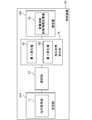
- the power control system of this embodiment includes a control device 10, a plurality of energy storage systems 31, and a plurality of power generation devices 60.
- the power generation device 60 is a power generation device that generates power using natural energy such as sunlight, wind power, small hydropower, and geothermal heat, and is a so-called renewable energy source.
- the power generation device 60 may be a large-scale power generation device (eg, mega solar) managed by a business operator, or a small-scale power generation device managed by a general household.
- the power generation device 60 includes a power generation element 62 and an output control device (power generation control device) 61.
- the power generation element 62 is a solar cell panel or the like, and generates power using natural energy.
- the output control device 61 includes a power conditioner and a power generation control unit.
- the power conditioner adjusts the power supplied from the power generation element 62 to the power system.
- the power generation control unit controls the power conditioner based on the power generation suppression control information received from the control device 10, and suppresses the power supplied from the power generation element 62 to the power system to be equal to or less than a predetermined value.
- the energy storage system 31 includes a storage control device 20 and an energy storage device 30.
- the energy storage device 30 is configured to store the supplied power as predetermined energy.
- a storage battery that stores the supplied power as power an electric vehicle (a storage battery installed therein), a heat pump water heater that converts the supplied power into heat energy and stores the heat energy, and the like can be considered, but are not limited thereto.
- the energy storage device 30 may be a large-scale energy storage device managed by a business operator or a small-scale energy storage device managed by a general household.
- the storage control device 20 controls the operation of the energy storage device 30.
- the control device 10 transmits information for controlling the power generation element 62 to the output control device 61. In addition, the control device 10 transmits information for controlling the energy storage device 30 to the storage control device 20.
- the control device 10 may be a so-called cloud server.
- These devices are connected to each other via a network 50 such as the Internet, and transmit / receive information to / from each other.
- a network 50 such as the Internet
- the power control system of the present embodiment is configured to charge and / or consume the total surplus output of the plurality of power generation devices 60 distributed over a wide area with the plurality of energy storage devices 30 distributed over a wide area.
- the total surplus output (W) is the amount by which the sum of the power generation outputs (W) of each of the plurality of power generation devices 60 exceeds the sum of the upper limit power generation output (W) of each of the plurality of power generation devices specified by the power generation suppression command. is there.
- the power generation suppression command is created, for example, by a power transmission / distribution company that manages power transmission / distribution of the power system.
- the power generation device 60 can be effectively utilized to the maximum extent without breaking the power supply-demand balance.
- the output of the power generation device 60 is as much as the energy storage device 30 cannot be charged and / or consumed. Do suppression. In such a case, the power generation device 60 can be effectively used as much as possible while giving priority to maintaining the supply and demand balance of the power system.
- a suppression time zone as shown in the figure and an upper limit power generation output (60% of the rated output of the power generation device 60) are determined in the power generation suppression command.
- the power that can be charged and / or consumed by the energy storage device 30 secured for the process of absorbing the total surplus output is 20% of the rated output of the power generation device 60.
- the total surplus output up to 20% of the rated output is charged and / or consumed by the energy storage device 30, but the power generation of the power generation device 60 is suppressed for more than this. .
- the power generation device 60 can output up to 80% of the rated output, it can output exceeding the upper limit power generation output (60%) determined by the power generation suppression command.
- the presence / absence of the power generation suppression of the power generation device 60 and the content thereof are determined according to the content of the power generation suppression command and the securing status of the energy storage device 30.
- Each device shown in FIG. 2 generally operates as follows.
- the control device 10 acquires a power generation suppression command for each of the plurality of power generation devices 60.
- the power generation suppression command includes a suppression implementation time zone and an upper limit power generation output for each unit time zone.
- the control device 10 determines (reserves) the energy storage device 30 that performs the process of charging and / or consuming the total surplus output during the suppression implementation time period.
- control device 10 determines the remaining surplus output (W) that cannot be charged or consumed by the energy storage device 30 determined based on the power generation suppression command and the content of the determination (the securing status of the energy storage device 30) and / or The remaining surplus power (Wh) is calculated.
- the control device 10 controls power generation suppression for suppressing power generation (output) for the remaining surplus output and / or the remaining surplus power amount. Information is transmitted to the power generator 60. When the remaining surplus output and the remaining surplus power amount are “0”, power generation suppression (output suppression) is not performed.
- the power generation device 60 includes a receiving unit that receives information from an external device and a transmitting unit that transmits information to the external device.
- the receiving unit of the power generation device 60 receives the power generation suppression control information from the control device 10.
- the transmission unit of the power generation device 60 transmits, for example, power generation related information (measured actual output value (W) or the like) indicating the power generation status of the own device to the control device 10.
- the power generation device 60 When there is a remaining surplus output and a remaining surplus power, the power generation device 60 receives power generation suppression control information from the control device 10. In this case, the power generation device 60 performs power generation suppression (output suppression) based on the power generation suppression control information in the suppression execution time zone. On the other hand, when the remaining surplus output and the remaining surplus power amount are “0”, the power generation device 60 generates power without power generation suppression (output suppression) even during the suppression implementation time period.
- control device 10 transmits control information for charging and / or consuming the total surplus output by the energy storage device 30 to the storage control device 20.
- the storage control device 20 includes a receiving unit that receives information from an external device and a transmitting unit that transmits information to the external device.
- the reception unit of the storage control device 20 receives the control information from the control device 10.
- the transmission unit of the storage control device 20 includes, for example, state information indicating the state of the energy storage device 30 (for example, SOC (State Of Charge), free capacity (Wh), charge amount (Wh), voltage, current, temperature. , Energy storage amount, error information, etc.) are transmitted to the control device 10.
- state information indicating the state of the energy storage device 30 for example, SOC (State Of Charge), free capacity (Wh), charge amount (Wh), voltage, current, temperature. , Energy storage amount, error information, etc.
- the storage control device 20 When the storage control device 20 receives the control information from the control device 10, the storage control device 20 charges and / or consumes the energy storage device 30 with predetermined charging power (W) and / or power consumption (W) determined according to the control information.
- W charging power
- W power consumption
- FIG. 3 shows an example of a functional block diagram of the control device 10.
- the control device 10 includes a reception unit 111, a selection unit 17, a remaining surplus calculation unit 18, and a transmission unit 191.
- the reception unit 111 includes a command acquisition unit 11.
- the remaining surplus calculation unit 18 includes a first calculation unit 181 and a second calculation unit 182.
- the transmission unit 191 includes a power generation suppression control information transmission unit 19.
- a plurality of power generation devices 60 and a plurality of energy storage devices 30 to be managed are registered in the control device 10.
- the control device 10 charges and / or consumes the total surplus output of the plurality of power generation devices 60 to be managed by the plurality of energy storage devices 30 to be managed.
- each power generation device 60 as shown in FIG. 4 is registered in the control device 10 in advance.
- a power generation device ID (Identification) for identifying each of the plurality of power generation devices 60, a rated output (W) of each power generation device 60, and an installation position of each power generation device 60 are associated with each other. Some of these may not be included, and other attribute information may be further registered.
- the rated output (W) here is the inverse of each photovoltaic power generation device determined by the total number of power conditioners and installed solar panels when the power generation device 60 is a photovoltaic power generation device, for example. It is the upper limit of tidal power.
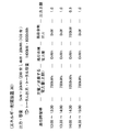
- attribute information (storage related information) of each energy storage device 30 as shown in FIG. 5 is registered in the control device 10 in advance.
- the energy storage device ID for identifying each of the plurality of energy storage devices 30, the type of each energy storage device 30, the rated output (W) of each energy storage device 30, and the rated capacity of each energy storage device 30. (Wh) and address information on the network 50 of the storage control device 20 that controls each energy storage device 30 are associated with each other. Some of these may not be included, and other attribute information may be further registered.
- the types shown in FIG. 5 are classified according to energy storage means, such as storage batteries and heat pump water heaters, types of batteries such as lead storage batteries and lithium ion storage batteries, and charge / discharge response characteristics of storage batteries. Indicates.
- energy storage means such as storage batteries and heat pump water heaters, types of batteries such as lead storage batteries and lithium ion storage batteries, and charge / discharge response characteristics of storage batteries. Indicates.
- the energy storage device 30 registered as a management target is limited to one type (for example, only a lithium ion storage battery), registration of the attribute information is unnecessary.
- the receiving unit 111 receives predetermined information from the external device.
- the command acquisition unit 11 is a command for the power generation device 60 that generates power using natural energy, and acquires a power generation suppression command including a suppression implementation time zone and an upper limit power generation output for each unit time zone (for example, 30 minutes). .
- the command acquisition unit 11 acquires a power generation suppression command for the power generation device 60 to be managed.
- the power generation suppression command may have different contents for each power generation device 60.
- FIG. 6 schematically shows an example of such a power generation suppression command.
- FIG. 6 shows a power generation suppression command for each power generation device 60 (for each power generation device ID).
- the upper limit power generation output for each unit time zone is indicated.
- the upper limit power generation output is shown in units of 30 minutes.
- the upper limit power generation output is indicated by a ratio (%) where the rated output (W) of each power generation device 60 is 100 (%). From the figure, it is understood that the upper limit power generation output in each unit time zone is different for each power generation device 60.
- the suppression implementation time zones of the two power generation devices 60 are the same from 13:00 to 15:00, but the suppression implementation time zones may be different for each power generation device 60. Moreover, the power generation device 60 that has received the power generation suppression command and the power generation device 60 that has not received the power generation suppression command may be mixed in the power generation device 60 to be managed.
- the content of the power generation suppression command may be common to a plurality of power generation devices 60.
- FIG. 7 schematically shows an example of such a power generation suppression command.
- the power generation suppression command is shown without being divided for each power generation device 40.
- the power generation devices 60 that have received the power generation suppression command and the power generation devices 60 that have not received the power generation suppression command may be mixed in the power generation devices 60 to be managed.
- the command acquisition unit 11 acquires information for identifying the power generation device 60 that is the target of the power generation suppression command, in addition to the power generation suppression command as illustrated in FIG. 7.
- zone is made into the unit of 30 minutes, you may make others, such as 1 hour unit, 15 minute unit, 5 minutes, 1 minute unit.
- the upper limit power generation output is shown as a ratio (%) to the rated output of each power generation device 60, but the upper limit output may be indicated by the output value itself (example: 400 kW).
- the power generation suppression command as described above is created, for example, by a transmission / distribution company system (hereinafter also referred to as “transmission / distribution company system”) that manages transmission / distribution of the power system, and is transmitted to a predetermined target person. Since the processing by the power transmission / distribution company system can be realized according to the conventional technology, a detailed description thereof is omitted here, but an outline of an example is as follows.
- the power transmission / distribution company system is based on the next day's attribute information (e.g., weather forecast, date, day of the week, event, etc.) based on the power demand forecast for the next day and the power generation device 60 connected to the power system. Make power generation predictions. And based on these predictions, the necessity of power generation suppression, the time zone in which power generation suppression should be performed, the region to be implemented, the power generation device 60 to be implemented, the total power generation amount to be suppressed (per unit time zone), each power generation The amount of suppression (for each unit time zone) of the device 60 is determined. Then, the power transmission and distribution company system transmits a power generation suppression command to a predetermined target at a predetermined timing (eg, a predetermined time on the previous day).
- a predetermined target e.g, a predetermined time on the previous day.
- the power transmission and distribution company system may be configured to transmit a power generation suppression command for each of the plurality of power generation devices 60 registered in the control device 10 to the control device 10.
- the command acquisition unit 11 receives a power generation suppression command from the power transmission and distribution company system.
- the power transmission and distribution company system may transmit a power generation suppression command to each of the plurality of power generation devices 60.
- the command acquisition unit 11 receives a power generation suppression command from each of the plurality of power generation devices 60 to be managed.
- the selection unit 17 determines a plurality of energy storage devices 30 that execute the surplus absorption process for charging or consuming the total surplus output during the suppression implementation time period.
- the total surplus output (W) is the amount by which the total measured value of the power generation output (W) of each of the plurality of power generation devices 60 exceeds the sum of the upper limit power generation output (W) of each of the plurality of power generation devices 60.
- the upper limit power generation output of each of the plurality of power generation devices 60 is determined based on the power generation suppression command.
- the upper limit power generation output of the power generation device 60 that has received the power generation suppression command is the upper limit power generation output determined by the power generation suppression command.
- the upper limit power generation output of the power generation device 60 that has not received the power generation suppression command is, for example, a rated output.
- the selection unit 17 determines a plurality of energy storage devices 30 that perform the surplus absorption processing.
- all the energy storage devices 30 registered in advance may participate in all surplus absorption processes and execute a process of charging and / or consuming the total surplus output.
- the selection unit 17 determines all the energy storage devices 30 registered in advance as the energy storage devices 30 that execute the surplus absorption process.
- At least a part of the plurality of energy storage devices 30 registered in advance may perform a process of charging and / or consuming the total surplus output by participating in the surplus absorption process.
- the selection unit 17 determines at least a part of the energy storage devices 30 participating in each surplus absorption process from the plurality of energy storage devices 30 registered in advance.
- the concept of “one surplus absorption process” will be described.
- the surplus absorption process (the surplus absorption process from 13:00 to 15:00 in the case of the example in FIG. 6) for one power generation suppression command (for example, the power generation suppression command for the next day shown in FIG. 6) for one time May be treated as
- surplus absorption processes (excess absorption processes from 13:00 to 15:00 in the example of FIG. 6) for one generation suppression instruction (example: power generation suppression instruction for the next day in FIG. 6)
- the surplus absorption process may be divided for each time period, and the surplus absorption process at 13:00 to 14:00 may be treated as one time, and the surplus absorption process at 14:00 to 15:00 may be treated as one time.
- the minimum unit for dividing the time zone is not limited to 30 minutes, and may be 15 minutes, 10 minutes, 1 minute, or a few dozen seconds. As the unit to be divided is made shorter, finer excess absorption processing becomes possible.
- surplus absorption processing for multiple power generation suppression commands may be handled as one time.
- the selection unit 17 determines at least a part of the energy storage devices 30 that participate in each surplus absorption process from the plurality of energy storage devices 30 registered in advance.
- rotation may be determined in advance, and a plurality of energy storage devices 30 may be configured to participate in the surplus absorption process sequentially according to the rotation.
- the selection unit 17 determines at least a part of the energy storage devices 30 that participate in each surplus absorption process based on the rotation.
- a user who manages each of the plurality of energy storage devices 30 may determine the conditions of the surplus absorption process to participate in and register them in the control device 10 in advance.
- Such conditions include, for example, time conditions (eg, participation from March to August, others not participating, etc.), time conditions (eg, participation from 9:00 to 17:00, others not participating, etc.), incentive conditions ( Example: Participation with surplus absorbed power of 5 yen / kWh or more), other conditions (eg, participation if the total time is less than 2 hours, non-participation if it exceeds 2 hours, etc.), but limited to these Not.
- the selection unit 17 determines at least a part of the energy storage devices 30 that match the participation condition from the plurality of energy storage devices 30 registered in advance.
- the selection unit 17 may recruit a user who manages each of the plurality of energy storage devices 30 to participate in the surplus absorption process every time. In this case, the selection unit 17 determines the energy storage device 30 of the user who has announced participation as the energy storage device 30 that participates in each surplus absorption process.
- the recruitment can be performed using communication means such as e-mail, an electronic bulletin board on the network 50, and social media.
- the user who manages each of the plurality of energy storage devices 30 may be able to determine the use conditions of the energy storage device 30 in the surplus absorption process.
- the usage conditions are the upper limit of output (W) that can be used in the surplus absorption process, the upper limit of capacity (Wh) that can be used in the surplus absorption process, etc. (that is, only a part of the output and capacity of the energy storage device 30 is surplus absorption) Participate in the process).
- the usage conditions may be determined for each surplus absorption process.
- the remaining surplus calculation unit 18 determines the remaining surplus output that cannot be charged or consumed by the determined energy storage device 30 based on the power generation suppression command and the content determined by the selection unit 17 before the suppression execution time period. (W) and / or residual surplus power (Wh) is calculated. Specifically, the remaining surplus calculation unit 18 calculates a remaining surplus output (W) and / or a remaining surplus power (Wh) for each unit time zone. Then, the power generation suppression content of the power generation device 60 is determined for each unit time zone.
- the remaining surplus calculation unit 18 calculates the remaining surplus output and / or the remaining surplus electric energy based on the use condition.
- the remaining surplus calculation unit 18 processes by the remaining surplus calculation unit 18 are “a first calculation unit 181 that calculates the total surplus output in the plurality of power generation devices based on the power generation related information and the upper limit power generation output in each of the plurality of power generation devices”, and “ The second surplus power is calculated based on the total surplus output and the storage related information in the plurality of energy storage devices 30 that absorb the total surplus output.
- W residual surplus output
- Wh residual surplus power
- the command acquisition unit 11 acquires a power generation suppression command as shown in FIG. 7 for 10 power generation devices 60 (rated output 500 kW) and 5 power generation devices 60 (rated output 400 kW). To do.
- the upper limit of the total surplus output (W) and the upper limit of the total surplus output amount (Wh) in each unit time zone are calculated.
- a unit time zone from 13:00 to 13:30 will be described as an example.
- the upper limit power generation output in the unit time zone is 80% of the rated output.
- the upper limit of the surplus output in the unit time zone is 20% of the rated output.
- the upper limit of the total surplus output is a value obtained by adding 20% of the rated output of each of the 15 power generation devices 60 that have received the power generation suppression command as shown in FIG.
- the total surplus output amount is a value obtained by multiplying the upper limit of the total surplus output by 0.5 hours corresponding to the unit time zone.
- the maximum upper limit of the total surplus output in the entire suppression implementation time zone is 2100 kW in the unit time zone from 14:00 to 14:30, and the total surplus output amount in the entire suppression implementation time zone It can be seen that the upper limit of 3150 kWh.
- the selection unit 17 uses 200 energy storage devices 30 that can use the output of 5 kW and the capacity of 6 kWh for the surplus absorption process, and the output of 4 kW and the capacity of 5 kWh for the surplus absorption process. Assume that 100 possible energy storage devices 30 have been determined (secured).
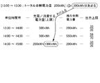
- the remaining surplus calculation unit 18 allocates an available capacity to each unit time zone, for example, as shown in FIG.
- Allocation rules are a matter of design. For example, it may be equally allocated to a plurality of unit time zones, or the operator of the control device 10 may determine how to allocate each time. However, in the case of renewable energy power generation, it is not possible to plan the power generation amount, so it is desirable to refer to the power generation prediction value in advance or to use a method that can reduce the power generation suppression amount stochastically throughout the suppression time zone.
- each power generation device may be individually allocated based on the power generation prediction value of each power generation device 60 and the upper limit power generation output. Specifically, when the power generation prediction value differs for each power generation device 60, the size of the power generation suppression control information is determined based on the amount by which the power generation prediction value for each power generation device 60 exceeds the upper limit power generation output. Also good. That is, a larger power generation suppression burden (a large amount of power generation is suppressed) may be allocated to the power generation apparatus 60 having a relatively large power generation prediction value that exceeds the upper limit power generation output.
- a smaller power generation suppression burden (a small amount of power generation is suppressed) may be allocated to the power generation device 60 having a relatively small power generation prediction value exceeding the upper limit power generation output. Note that the power generation device 60 whose power generation prediction value is relatively smaller than the upper limit power generation output does not receive the power generation suppression control information, or does not need to suppress power generation even if it is received.
- the control device 10 calculates a surplus output that is a power generation output that exceeds the upper limit power generation output using the value of the power generation prediction for each power generation device 60, and in the plurality of power generation devices 60 that the power generation output is equal to or higher than the upper limit power generation output.
- the ratio of the surplus output to the total surplus output may be calculated for each power generation device 60.
- the control apparatus 10 may allocate for every power generation apparatus 60 based on the burden coefficient (ratio) for every power generation apparatus 60 and power generation suppression control information.
- the control apparatus 10 may transmit the electric power generation suppression information which shows the content allocated individually for every electric power generating apparatus 60.
- the amount of power allocated to each unit time zone needs to be equal to or less than the product of “total output of multiple energy storage devices 30” and “time of each unit time zone”.
- the amount of power allocated to each unit time zone needs to be 700 kWh or less, which is the product of 1400 kW (see FIG. 9) and 0.5 hour.
- W residual surplus output
- the allocation is performed so as to satisfy the condition.
- the power generation amount from 13:00 to 14:00 is relatively large, but the power generation amount from 14:00 to 15:00 is relatively small (power generation suppression command (There is also a power source that does not reach the upper limit power generation output due to power generation), and therefore, the situation of the upper limit power generation output due to the power generation suppression command is also taken into consideration, from 13:00 to 13:30, 13:30 to 14:00, and 14 From 0:00 to 14:30, 500 kWh (necessary output 1000 kW) is allocated, and from 14:30 to 15:00, 200 kWh (necessary output 400 kW) is allocated.
- a total of 1000 kW is output by the plurality of energy storage devices 30.
- the total surplus output is charged and / or consumed with the total capacity of 500 kWh as the upper limit of the capacity, and in the unit time zone from 14:30 to 15:00, the total output of 400 kW with the plurality of energy storage devices 30 is the upper limit of the output, This means that the total surplus output is charged and / or consumed with a total capacity of 200 kWh as the upper limit of the capacity.
- the remaining surplus calculation unit 18 calculates the capacity allocated to each unit time zone (the amount of power charged / charged (upper limit)) and the total surplus output for each unit time zone. The difference from the upper limit of the power (see FIG. 8) is calculated as the remaining surplus power amount in each unit time zone.
- the residual surplus calculating unit 18 increases the value of power generation suppression (output suppression) (the value of power generation suppression information is increased) as the residual surplus power and / or the residual surplus power amount (value of residual surplus power information) is large.
- the remaining surplus calculating unit 18 allocates power generation suppression (output suppression) corresponding to the remaining surplus power amount to the plurality of power generation devices 60.
- power generation suppression output suppression
- the rule to allocate is a design matter, you may allocate equally to the several electric power generating apparatus 60.
- power generation suppression (output suppression) for the remaining surplus power may be apportioned by a plurality of power generation devices 60.
- FIG. 9 shows an example in which the ratio of suppression with respect to the rated output is evenly arranged by a plurality of power generators 60.
- the value of “output upper limit” in each unit time zone shown in FIG. 9 indicates the content of power generation suppression (output suppression). This indicates a suppression ratio (output upper limit) with respect to the rated output, and is commonly applied to all the power generation devices 60.
- the output upper limit is set to M (M is a percentage value and 0 ⁇ M ⁇ 1) for ten power generators 60 (see FIG. 8) with a rated output of 500 kW, and similarly, the rated output is 400 kW. Assume that the output upper limit is set to M for the five power generation devices 60. In this case, the maximum amount of power suppressed in the unit time zone is 500 kW ⁇ (1 ⁇ M) ⁇ 10 units ⁇ 0.5 hours + 400 kW ⁇ (1 ⁇ M) ⁇ 5 units ⁇ 0.5 hours. What is necessary is just to calculate M so that this value may become the amount of remaining surplus power in each unit time zone.
- Example 2 An example in which the remaining surplus power (Wh) is mainly generated and power generation suppression (output suppression) for this amount has been described.
- Example 2 an example will be described in which residual surplus output (W) is generated and power generation suppression (output suppression) corresponding to this amount is performed.
- the command acquisition unit 11 acquires power generation suppression commands as shown in FIG. 7 for 10 power generation devices 60 (rated output 500 kW) and 5 power generation devices 60 (rated output 400 kW).
- the upper limit of the total surplus output (W) and the upper limit of the total surplus output amount (Wh) in each unit time zone are calculated.
- the selection unit 17 can use 200 energy storage devices 30 that can use the output of 5 kW and the capacity of 20 kWh for the surplus absorption process, and the output of 4 kW and the capacity of 20 kWh for the surplus absorption process. Assume that 100 energy storage devices 30 are determined (secured).
- the sum (3150 kWh) of the total surplus output amount of the plurality of unit time zones shown in FIG. 8 is equal to or less than the total capacity (6000 kWh) of the energy storage device 30 shown in FIG. That is, a sufficient capacity is secured to charge and / or consume the upper limit of the total surplus output amount.
- the remaining surplus calculation unit 18 calculates the remaining surplus output in the other unit time zone as 0 kW.
- the remaining surplus calculation unit 18 determines the suppression content for performing power generation suppression (output suppression) for the remaining surplus output in the unit time zone from 14:00 to 14:30.
- the rule for allocating power generation suppression (output suppression) for the remaining surplus output to the plurality of power generation devices 60 is a design matter, here, the suppression ratio for the rated output is assumed to be evenly distributed among the plurality of power generation devices 60. .
- the output upper limit is set to M (M is a percentage value and 0 ⁇ M ⁇ 1) for ten power generators 60 (see FIG. 8) with a rated output of 500 kW, and similarly, the rated output is 400 kW. Assume that the output upper limit is set to M for the five power generation devices 60. In this case, the output power to be suppressed is 500 kW ⁇ (1 ⁇ M) ⁇ 10 units + 400 kW ⁇ (1 ⁇ M) ⁇ 5 units. What is necessary is just to calculate M so that this value becomes the remaining surplus output of each unit time zone.
- the suppression ratio for the remaining surplus output and / or the remaining surplus power amount is not made to coincide among the plurality of power generators 60, and the power generation prediction situation for each power generator, etc. In consideration of the above, it may be different for each power generator 60. Even in this case, it is possible to calculate the output upper limit (e.g., the suppression ratio with respect to the rated output) of each power generator 60 by the same concept.
- the transmission unit 191 transmits predetermined information to the external device.
- the power generation suppression control information transmission unit 19 transmits power generation suppression control information for suppressing power generation for the remaining surplus output and / or the remaining surplus power amount to each of the plurality of power generation devices 60.
- the power generation suppression control information may include an upper limit power generation output for each unit time zone of the suppression implementation time zone.
- the power generation suppression control information transmission unit 19 can transmit power generation suppression information before the suppression implementation time period.
- the power generation suppression control information transmission unit 19 uses the output upper limit (eg, the suppression ratio with respect to the rated output; see the output upper limit in FIGS. 9 and 10) for each unit time zone calculated by the remaining surplus calculation unit 18 as a plurality of power generators. 60.
- the output upper limit eg, the suppression ratio with respect to the rated output; see the output upper limit in FIGS. 9 and 10.
- the transmission unit 191 can transmit control information for charging and / or consuming the total surplus output by the energy storage device 30 to the storage control device 20.
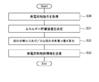
- the command acquisition unit 11 is a command for the power generation device 60 that generates power using natural energy, and acquires a power generation suppression command including a suppression execution time zone and an upper limit power generation output for each unit time zone (S30). .
- the selection unit 17 determines (reserves) a plurality of energy storage devices 30 that perform the surplus absorption process for charging and / or consuming the total surplus output during the suppression implementation time period (S31).
- the remaining surplus calculation unit 18 is based on the power generation suppression command acquired in S30 and the content determined by the selection unit 17 in S31, and the remaining surplus output that cannot be charged and / or consumed by the determined energy storage device 30. (W) and / or remaining surplus power (Wh) is calculated (S32).
- the power generation suppression control information transmission unit 19 transmits power generation suppression control information for suppressing power generation for the remaining surplus output and / or the remaining surplus power amount to each of the plurality of power generation devices 60 (S33).
- the process of S33 may be terminated without being executed, or power generation suppression information indicating that may be transmitted. .
- S30 to S33 The processing of S30 to S33 is performed before the suppression implementation time period specified by the power generation suppression command.
- the power generation device 60 that has received the power generation suppression control information transmitted in S33 performs power generation suppression (output suppression) based on the power generation suppression control information during the suppression execution time period specified by the power generation suppression command.
- the power generation control unit of the power generation device 60 controls the power conditioner based on the power generation suppression control information received from the power generation suppression control information transmission unit 19, and generates power suppression from the power supplied from the power generation element to the power system. Suppressed below the upper limit power generation output specified by the control information.
- the storage control device 20 of FIG. 2 controls the energy storage device 30 according to the control information received from the control device 10, and is charged and / or consumed with predetermined charging power and / or power consumption.
- the details of the processing are design matters, and any configuration can be adopted. An example will be described in the following embodiment.
- the power control system of the present embodiment charges and / or consumes the total surplus output of the plurality of power generation devices 60 distributed over a wide area with the plurality of energy storage devices 30 distributed over a wide area.
- the power control system of the present embodiment charges and / or consumes the total surplus output of the plurality of power generation devices 60 distributed over a wide area with the plurality of energy storage devices 30 distributed over a wide area.
- the power generation device is generated by the amount of power that cannot be charged and / or consumed (estimated or predicted).
- 60 power generation suppression (output suppression) is performed. That is, the energy storage device 30 and the power generation device 60 absorb the total surplus output (charging and / or consumption, power generation suppression (output suppression)).
- the absorption (charging and / or consumption) of the total surplus output by the energy storage device 30 is utilized as much as possible, and only the shortage is supplemented by absorption by the power generation device 60 (power generation suppression (output suppression)).
- the power generation device 60 can be effectively used as much as possible while giving priority to maintaining the supply and demand balance of the power system.
- the control device 10 of the present embodiment can detect the occurrence of an event whose content of the power generation suppression control information should be changed during the suppression execution time zone.
- the control device 10 transmits new power generation suppression control information to the plurality of power generation devices 60 in response to the detection of the event.
- the determined (secured) capacity of the energy storage device 30 can be used without waste.
- the power supply / demand balance of the power system can be maintained appropriately. Details will be described below.
- the configuration of the storage control device 20 and the energy storage device 30 of the power control system of this embodiment is the same as that of the first embodiment.
- configurations of the control device 10 and the power generation device 60 will be described.
- FIG. 12 shows an example of a functional block diagram of the control device 10 of the present embodiment.
- the control device 10 includes a reception unit 111, a selection unit 17, a remaining surplus calculation unit 18, a transmission unit 191, and an event detection unit 16.
- the configurations of the reception unit 111 and the selection unit 17 are the same as those in the first embodiment.
- the event detection unit 16 detects the occurrence of an event whose content of the power generation suppression control information should be changed during the suppression execution time zone.
- the event detecting unit 16 determines that the total surplus output amount in the first unit time zone is the first unit by the remaining surplus calculating unit 18.
- An event (first event) that is less than “the amount of power charged and / or consumed by a plurality of energy storage devices 30 (“the amount of power to be charged and / or consumed (upper limit) ”in FIG. 9)” assigned in the time zone ) Is detected.
- the remaining surplus electric power is generated in each unit time zone, and “in the plurality of energy storage devices 30 determined according to the unit time zone from 13:00 to 13:30”.
- the amount of electric power to be charged and / or consumed is 500 kWh.
- the event detection unit 16 changes the content of the power generation suppression control information. Detect as an event to be performed.
- the event detection unit 16 determines the “amount of power charged and / or consumed by the plurality of energy storage devices 30 in each of the plurality of unit time zones” (“power to be charged and / or consumed in FIG. 9) determined by the remaining surplus calculation unit 18. Information indicating the amount (upper limit) ")" is held in advance. And the event detection part 16 calculates the result of a total surplus output amount based on the measured value of each of the some power generator 60 for every unit time slot
- the event detection unit 16 monitors the state of the communication path from the control device 10 to the storage control device 20 and the state of the energy storage device 30 (full charge or depletion state of the storage battery, SOC value, etc.), and implements suppression.
- the energy storage device 30 is used for another purpose, such as a communication failure, a significant communication delay, an abnormal rise in the temperature of the energy storage device 30, an overcurrent, or a voltage abnormality during the time period. Detecting an event (second event) in which a part of the plurality of energy storage devices 30 determined by the selection unit 17 cannot execute the surplus absorption process due to the loss of the energy storage capacity due to the influence such as Also good. Other causes of the inability to perform the surplus absorption process may be, for example, a failure of the energy storage device 30, but are not limited thereto.
- the event detection unit 16 may acquire a signal indicating the occurrence of the second event from, for example, a monitoring device that monitors the operation of the energy storage device 30 that is executing the surplus absorption process.
- a monitoring device that monitors the operation of the energy storage device 30 that is executing the surplus absorption process.
- the operator of the control device 10 may input the signal to the control device 10.
- the event detection part 16 may detect a 2nd event by acquisition of the said signal.
- each storage control device 20 may have the monitoring device.
- the remaining surplus calculating unit 18 recalculates the remaining surplus output and / or the remaining surplus electric power according to the event detection by the event detecting unit 16. Then, the remaining surplus calculation unit 18 re-determines the power generation suppression content for each of the plurality of power generation devices 60 based on the result.
- the remaining surplus calculation unit 18 has a plurality of energies in a unit time zone in which the first event occurs (hereinafter, “first unit time zone”). Based on the amount of power determined to be charged and / or consumed by the storage device 30 (“charged and / or consumed power (upper limit)” in FIG. 9), the total surplus output amount in the first unit time zone is obtained. The subtracted value (hereinafter “unused capacity”) is calculated.
- the remaining surplus calculation unit 18 allocates the unused capacity in a unit time zone after the first unit time zone. For example, you may allocate to the unit time slot
- the amount of power determined to be charged and / or consumed by the plurality of energy storage devices 30 in a predetermined unit time zone (“the amount of power to be charged and / or consumed (upper limit)” in FIG. 9) is allocated. Increase by a certain amount. In this way, the remaining surplus calculation unit 18 re-determines the amount of power to be charged and / or consumed by the plurality of energy storage devices 30 for each unit time zone.
- the remaining surplus calculation unit 18 determines the power generation suppression content of the plurality of power generation devices 60 according to the newly calculated remaining surplus power amount in each unit time zone. The method of determining the power generation suppression content of the plurality of power generation devices 60 according to the remaining surplus power is as described above.
- the remaining surplus calculation unit 18 determines the amount of power to be charged and / or consumed by the plurality of energy storage devices 30 in each of the plurality of unit time zones as shown in FIG. 9 before the suppression implementation time zone. To do. That is, 500 kWh is determined in the unit time zone from 13:00 to 13:30, 13:30 to 14:00, and 14:00 to 14:30, and from 14:30 to 15:00 In the unit time zone, 200 kWh is determined.
- the remaining surplus calculation unit 18 allocates 300 kWh of power in the unit time zone from 14:30 to 15:00.
- the electric energy determined to be charged and / or consumed by the plurality of energy storage devices 30 in the unit time zone is 500 kWh
- the remaining surplus electric energy is 200 kWh.
- the residual surplus calculation part 18 grasps
- the power generation suppression control information transmission unit 19 outputs a plurality of newly determined power generation suppression control information according to recalculation of the residual surplus output and / or the residual surplus power amount by the residual surplus calculation unit 18. It transmits to each power generator 60.
- Used capacity occurs when the total capacity of the determined (reserved) energy storage devices 30 is insufficient and the remaining surplus power is generated, by effectively utilizing such unused capacity, the power generator 60 can be made more effective. Can be used effectively. Since the first event is detected, the power generation suppression amount can be reduced.
- the power generation device 60 can be used more effectively.
- the power generation suppression contents for the plurality of power generation devices 60 can be reviewed.
- the power generation suppression amount of each of the plurality of power generation devices 60 can be changed to increase. As a result, it is possible to reduce the disadvantage of excessive power supply to the power system. Since the 2nd event was detected, it can change in the direction which increases power generation suppression amount.
- ⁇ Third Embodiment> configuration examples of the storage control device 20 and the energy storage device 30 will be described. Specifically, a specific example of processing for charging and / or consuming the total surplus output of the plurality of power generation devices 60 will be described. In addition, according to this embodiment, the time lag between the timing when the surplus output is reversely flowed from the power generation device 60 to the power system and the timing when the energy storage device 30 charges / consumes the surplus output can be reduced. . This will be described below.
- the configuration of the power generation device 60 is the same as in the first and second embodiments.
- the control device 10 includes a reception unit 111, a surplus calculation unit 12, a burden coefficient determination unit 13, a selection unit 17, a remaining surplus calculation unit 18, and a transmission unit 191.
- FIG. The reception unit 111 includes a command acquisition unit 11.
- the transmission unit 191 includes a surplus notification unit 14, a burden coefficient notification unit 15, and a power generation suppression control information transmission unit 19.
- the remaining surplus calculation unit 18 includes a first calculation unit 181 and a second calculation unit 182.
- the surplus notification part 14, the burden coefficient notification part 15, and the power generation suppression control information transmission part 19 can communicate via the same communication part.
- the configurations of the reception unit 111, the event detection unit 16, the selection unit 17, the remaining surplus calculation unit 18, and the power generation suppression control information transmission unit 19 are the same as those in the first and second embodiments.
- the burden coefficient determination unit 13 determines a burden coefficient indicating the burden ratio of the surplus absorption process corresponding to each of the plurality of energy storage devices 30 determined as the apparatus that executes the surplus absorption process by the selection unit 17.
- the burden coefficient determination unit 13 determines the burden coefficient before the surplus absorption process is started. For example, the burden coefficient determination unit 13 determines the burden coefficient by the following method.
- a user who manages each of the plurality of energy storage devices 30 can determine the use conditions of the energy storage device 30 in the surplus absorption process.
- the usage conditions include an output upper limit (W) that can be used in the surplus absorption process, a capacity upper limit (Wh) that can be used in the surplus absorption process, and the like.
- the burden coefficient determination unit 13 determines the burden coefficient based on, for example, such usage conditions and the design of each energy storage device 30 (see FIG. 5). For example, a burden coefficient that is a heavier burden ratio, that is, a larger burden coefficient is determined for the energy storage device 30 having a large available output upper limit and a usable capacity upper limit.
- the specific calculation method is a design matter.
- the burden coefficient indicates the burden ratio of each energy storage device 30 with respect to the total surplus output.
- the burden coefficient may be expressed as a percentage. In the case of this example, for example, the energy storage device 30 for which a burden coefficient of “0.05” is determined is charged and / or consumed at an output of 5% of the total surplus output during the surplus absorption process.
- the burden coefficient may be a value obtained by standardizing the above percentage value. For example, a value obtained by multiplying the percentage value by a predetermined value N (a value equal to or greater than the upper limit value of the total surplus output (W)) may be used as the burden coefficient.
- the burden coefficient determination unit 13 can determine a burden coefficient for each unit time zone of the suppression implementation time zone.
- the burden coefficient notification unit 15 transmits the burden coefficient of each energy storage device 30 determined by the burden coefficient determination unit 13 to each of the plurality of storage control devices 20 that control the operation of each energy storage device 30.
- the burden coefficient may be transmitted in association with information capable of identifying a surplus absorption process in which the burden coefficient is effective. For example, it may be transmitted in association with an effective period or time, such as “December 4, 2015, 13:00 to 15:00”.
- the transmission timing of the burden coefficient is an arbitrary timing after the determination by the burden coefficient determination unit 13 and before the start of the surplus absorption process.
- the burden coefficient notification unit 15 sequentially transmits a burden coefficient having contents corresponding to each energy storage device 30 to each of the plurality of storage control devices 20.
- the surplus calculation unit 12 repeatedly calculates the total surplus output based on the actual power generation value of each of the plurality of power generation devices 60 during the suppression implementation time period.
- the total surplus output (W) is the amount by which “the total of the measured values of the power generation outputs (W) of each of the plurality of power generation devices 60” exceeds “the total of the upper limit power generation output (W) of each of the plurality of power generation devices 60”. is there.
- FIG. 20 shows an example of a functional block diagram of the surplus calculation unit 12.
- the surplus calculation unit 12 includes a first addition unit 121, a subtraction unit 122, a specification unit 123, and a second addition unit 124.
- the receiving unit 111 receives power generation related information (power generation output: actual measurement value) regarding each power generation state from each of the plurality of power generation devices 60 for each predetermined period T1a.
- power generation related information power generation output: actual measurement value
- each of the plurality of power generation devices 60 obtains data on the power generation output (instantaneous value (W)) of each power generation device 60 measured at a predetermined time interval (for example, 400 msec) by real-time processing during the suppression execution time zone. Get repeatedly. And each of the some electric power generating apparatus 60 transmits the said measured value to the control apparatus 10 repeatedly with the period T1a (example: 10 sec) longer than the said time interval. For example, the power generation device 60 transmits representative values (eg, average value, maximum value, minimum value, mode value, intermediate value, etc.) of a plurality of measurement values obtained during the period T1a to the control device 10. .
- representative values eg, average value, maximum value, minimum value, mode value, intermediate value, etc.
- the plurality of power generation devices 60 transmit the measurement values to the control device 10 while shifting the timing by a time smaller than the period T1a in order to prevent the transmission data from being congested.
- the first adding unit 121 acquires the power generation related information received by the receiving unit 111. Then, the first addition unit 121 calculates the sum of the power generation outputs (actually measured values) of the plurality of power generation devices 60. The first addition unit 121 repeatedly calculates, for example, “the sum of the power generation outputs (measured power generation actual values) by each of the plurality of power generation devices 60” in the same cycle as the cycle T1a.
- the specifying unit 123 acquires the power generation suppression command acquired by the command acquisition unit 11. Thereafter, the specifying unit 123 specifies the upper limit power generation output (W) of each power generation device 60.
- the upper limit power generation output of the power generation device 60 that has received the power generation suppression command is the upper limit power generation output determined by the power generation suppression command.
- the upper limit power generation output of the power generation device 60 that has not received the power generation suppression command is, for example, a rated output.
- the second addition unit 124 calculates the sum of the upper limit power generation outputs of the plurality of power generation devices 60.
- the specifying unit 123 may specify the upper limit power generation output of each of the plurality of power generation devices 60 for each unit time zone defined by the power generation suppression command. And the 2nd addition part 124 may calculate "the total of the upper limit electric power generation output of each of the some electric power generating apparatus 60" for every unit time slot
- the subtraction unit 122 calculates the sum of the power generation outputs (actually measured values) of the plurality of power generation devices 60 calculated by the first addition unit 121 and the sum of the upper limit power generation outputs of the plurality of power generation devices 60 calculated by the second addition unit 124.
- the difference (total surplus output) is repeatedly calculated at a predetermined cycle T1.
- the subtraction unit 122 calculates “the plurality of power generation devices 60 in the corresponding time zone”.
- the total surplus output is calculated using the “total of the upper limit power generation output by each”.
- the surplus notification unit 14 repeatedly transmits surplus output information indicating the total surplus output to the plurality of storage control devices 20 during the suppression execution time period.
- the surplus output information may be a value of the total surplus output (W) itself calculated by the surplus calculation unit 12 or may be a value obtained by standardizing the value. For example, the value obtained by dividing the total surplus output (W) by a predetermined value N (a value equal to or greater than the upper limit value of the total surplus output (W). For example, the total rated output of all the power generation devices 60 to be suppressed-the maximum upper limit power output). May be a normalized value.
- the predetermined value N is the same value as the predetermined value N used for normalization of the burden coefficient described above.
- the surplus notification unit 14 repeatedly transmits surplus output information indicating the total surplus output repeatedly calculated by the surplus calculation unit 12 in the cycle T1 to the storage control device 20 in the same cycle.
- the surplus notification unit 14 can simultaneously transmit surplus output information to the storage control device 20.
- the present invention is not limited thereto.
- FIG. 15 shows an example of a functional block diagram of the storage control device 20.
- the storage control device 20 includes a burden coefficient receiving unit 21, a surplus receiving unit 22, a charging power determining unit 23, and an operation control unit 24.
- the burden coefficient receiving unit 21 and the surplus receiving unit 22 can communicate via the same communication unit.
- FIG. 21 shows another example of a functional block diagram of the storage control device 20.
- the storage control device 20 shown in the figure includes a load coefficient receiving unit 21, a surplus receiving unit 22, a charging power determination unit 23, an operation control unit 24, and a monitoring device 25.
- the burden coefficient receiving unit 21 receives the burden coefficient individually transmitted by the burden coefficient notification unit 15 to each of the plurality of storage control devices 20 before the start of the surplus absorption process.
- the surplus receiving unit 22 receives surplus output information simultaneously transmitted by the surplus notification unit 14 to the plurality of storage control devices 20 during the suppression implementation time period.
- the surplus receiving unit 22 repeatedly receives surplus output information repeatedly transmitted by the surplus notifying unit 14 in the cycle T1.
- the charging power determining unit 23 is an energy storage device that charges and / or consumes the power of the total surplus output based on the burden coefficient received by the burden coefficient receiving unit 21 and the latest surplus output information received by the surplus receiving unit 22. 30 charging powers and / or power consumption are determined. When the surplus receiving unit 22 repeatedly receives surplus output information, the charging power determining unit 23 repeatedly determines charging power and / or power consumption accordingly.
- the burden coefficient is a percentage (for example, “0.05”) indicating the burden ratio of each energy storage device 30 with respect to the total surplus output
- the surplus output information is the value (W) of the total surplus output itself.
- the charging power determination unit 23 can determine the product of the total surplus output and the burden coefficient as charging power (W) / power consumption (W).
- the charging power determination unit 23 charges the product of the information indicating the total surplus output (value obtained by normalizing the total surplus output) and the burden coefficient. It can be determined as power (W) / power consumption (W).
- the operation control unit 24 controls the energy storage device 30 to execute the surplus absorption process during the suppression implementation time period.
- the operation control unit 24 causes the energy storage device 30 to charge and / or consume the charging power and / or power consumption determined by the charging power determination unit 23.
- the charging power determination unit 23 repeatedly determines charging power and / or power consumption during the suppression execution time period.
- the operation control unit 24 causes the energy storage device 30 to charge and / or consume with the newly determined charging power and / or power consumption.
- the monitoring device 25 acquires (detects and measures) state information indicating the state of the energy storage device 30 and repeatedly transmits it to the control device 10.
- the state information is, for example, SOC, free capacity (Wh), charge amount (Wh), voltage, current, temperature, energy storage amount, error information, and the like.
- the power transmission / distribution company system is, for example, based on the next day's attribute information (eg, weather forecast, date, day of the week, event, etc.), the power demand forecast for the next day and the power generator connected to the power system Power generation prediction by 60 is performed. And based on these predictions, the necessity of power generation suppression, the time zone in which power generation suppression should be performed, the region to be implemented, the power generation device 60 to be implemented, the total amount to be suppressed (per unit time zone), each power generation device 60 suppression amounts (per unit time zone) and the like are determined. Then, the power transmission and distribution company system transmits a power generation suppression command for the next day to a predetermined target at a predetermined timing (eg, a predetermined time on the previous day).
- a predetermined target eg, a predetermined time on the previous day.
- the power generation suppression command includes the suppression implementation time zone and the upper limit power generation output for each unit time zone (see FIGS. 6 and 7).
- the power transmission and distribution company system transmits to the control device 10 power generation suppression commands for the plurality of power generation devices 60 registered in the control device 10.
- the power transmission and distribution company system determines whether the power generation suppression command is a target of the power generation suppression command. Information for identifying the power generation device 60 is transmitted to the control device 10.
- the power transmission and distribution company system may transmit a power generation suppression command to each of the plurality of power generation devices 60 subject to power generation suppression.
- a power generation suppression command is transmitted from each of the power generation devices 60 to the control device 10, whereby the control device 10 grasps the contents of the power generation suppression command.
- control device 10 determines the energy storage device 30 that participates in the surplus absorption process for the power generation suppression command acquired in S10.
- the specific example of the process to determine is as above-mentioned.
- control device 10 may invite a user who manages each of the plurality of registered energy storage devices 30 to participate in the surplus absorption process. And the control apparatus 10 may determine the energy storage apparatus 30 of the user who announced participation as the energy storage apparatus 30 which participates in a surplus absorption process. Note that the order of S10 and S11 may be switched.
- control device 10 determines the remaining surplus output and / or the remaining surplus power that cannot be charged and / or consumed by the determined energy storage device 30 based on the power generation suppression command acquired in S10 and the content determined in S11. Is calculated. A specific example of the calculation process is as described above.
- control device 10 when there is a remaining surplus output and / or a remaining surplus power amount, the control device 10 generates power generation suppression control information for suppressing power generation for the calculated remaining surplus output and / or remaining surplus power amount. Generate for each.
- a specific example of this processing is as described above.
- the control device 10 determines a burden coefficient for each energy storage device 30 determined in S11.
- a specific example of the process for determining the burden coefficient is as described above.
- the control apparatus 10 can determine the burden coefficient of each of the some storage control apparatuses 20 for every unit time slot
- control device 10 transmits the power generation suppression control information generated in S12 to each of the plurality of power generation devices 60.
- the control device 10 may notify the plurality of power generation devices 60 of the suppression execution time zone.
- the control device 10 When the remaining surplus output and / or the remaining surplus power is “0”, the control device 10 does not have to transmit the power generation suppression control information in S14. Alternatively, power generation suppression control information indicating that the remaining surplus output and / or the remaining surplus power amount is “0” may be transmitted.
- control device 10 transmits the burden coefficient of each of the plurality of energy storage devices 30 determined in S13 to the storage control device 20 that controls each of the energy storage devices 30 to be controlled.
- S15 is preferably performed before the suppression implementation time zone, but may be performed at the beginning of the suppression implementation time zone. S15 may determine a burden coefficient (may be the same coefficient) for a plurality of suppression time zones when a power generation suppression command is received for each suppression time zone (every minute or every few seconds) in real time.
- each of the plurality of power generation devices 60 performs power generation suppression (output suppression) based on the power generation suppression control information.
- the power generation device 60 performs the suppression. Even during the time period, power generation is continued without power generation suppression (output suppression).
- each of the plurality of power generation devices 60 repeatedly transmits the power generation actual measurement value (instantaneous value (W)) of the power generation device 60 to the control device 10 in a cycle T1.
- the output (W) of the power generator 60 is measured at a measurement interval (eg, 400 msec) smaller than the cycle T1, and a representative value (eg, an average value) of a plurality of measured values (W) obtained during the cycle T1.
- the maximum value, the minimum value, the mode value, the intermediate value, the integrated value during the period T1, etc.) are transmitted to the control device 10.
- the plurality of power generation devices 60 transmit measured power generation values while shifting the timing by a time smaller than the period T1 in order to prevent the transmission data from being congested.
- control device 10 repeatedly calculates the total surplus output in the cycle T1.
- the total surplus output is calculated based on the actual power generation value of each of the plurality of power generation devices 60 repeatedly acquired in S16.
- the method for calculating the total surplus output is as described above.
- control device 10 repeatedly transmits the surplus output information indicating the total surplus output to the plurality of storage control devices 20 in the period T1.
- the control device 10 can simultaneously transmit the surplus output information to the plurality of storage control devices 20 using means such as multicast.
- each of the plurality of storage control devices 20 charges each storage control device 20 in the surplus absorption process based on the burden coefficient received in S15 and the surplus output information (latest surplus output information) received repeatedly in S18.
- the power and / or power consumption is determined repeatedly.
- the storage control device 20 determines new charge power and / or power consumption based on the new surplus output information.
- the burden coefficient is a percentage (for example, “0.05”) indicating the burden ratio of each energy storage device 30 with respect to the total surplus output
- the surplus output information is the value (W) of the total surplus output itself.
- the charging power determination unit 23 can determine the product of the total surplus output and the burden coefficient as charging power (W) / power consumption (W).
- the storage control device 20 uses the burden coefficient of the unit time slot corresponding to the current time to calculate the charging power and / or the power consumption. decide.
- each of the plurality of storage control devices 20 controls each of the plurality of energy storage devices 30 so as to be charged and / or consumed with the latest charging power and / or power consumption determined in S19.
- the control device 10 acquires a power generation suppression command.
- the control device 10 has acquired a power generation suppression command as shown in FIG. 7 for ten power generation devices 60 with a rated output of 500 kW and five power generation devices 60 with a rated output of 400 kW.
- the upper limit of the total surplus output (W) and the upper limit of the total surplus output amount (Wh) in each unit time zone are calculated. The calculation method is as described above.
- the control device 10 determines the energy storage device 30 that participates in the surplus absorption process for the power generation suppression command.
- 200 energy storage devices 30 that can use an output of 5 kW and a capacity of 6 kWh by surplus absorption processing and 100 energy storage devices 30 that can use an output of 4 kW and a capacity of 5 kWh by surplus absorption processing are determined.
- the determined total output of the plurality of energy storage devices 30 is 1400 kW, and the total capacity is 1700 kWh.
- the control device 10 calculates the remaining surplus output and / or the remaining surplus power for each unit time zone. In addition, when there is a remaining surplus output and / or a remaining surplus power amount, the control device 10 generates power generation suppression control information for suppressing power generation for the calculated remaining surplus output and / or remaining surplus power amount. Generate for each. Here, it is assumed that it is calculated and determined as shown in FIG. The calculation and determination method is as described above.
- the control device 10 calculates a burden coefficient for each of the plurality of energy storage devices 30.
- the burden ratios of the determined 300 energy storage devices 30 are equalized.
- the burden ratio (percentage) of each of the 300 energy storage devices 30 is 1/300.
- this value may be used as the burden coefficient, here, a value obtained by standardizing the value is used as the burden coefficient.
- FIG. 17 shows a standard value obtained by multiplying the burden ratio (percentage) by the upper limit of the total surplus output (W) for each unit time zone as a burden coefficient for each unit time zone.
- a different burden coefficient may be determined for each energy storage device 30.
- control device 10 transmits the power generation suppression control information to the plurality of power generation devices 60 based on the content determined in S12.
- the output upper limit ratio to the rated output for each unit time zone shown in FIG. 9 is transmitted.
- control device 10 transmits the burden coefficient determined in S13 to each of the plurality of storage control devices 20.
- the power generation device 60 performs power generation suppression (output suppression) based on the power generation suppression control information received in S14.
- the power generation device 60 that has acquired the output upper limit (ratio to the rated output) for each unit time zone shown in FIG. 9 controls the output for each unit time zone to be equal to or lower than the output upper limit shown in FIG.
- each of the plurality of power generation devices 60 repeatedly transmits the power generation actual measurement value (instantaneous value (W)) to the control device 10 in the cycle T1.
- control device 10 repeatedly calculates the total surplus output in the cycle T1 based on the data received in S16.
- the control device 10 transmits surplus output information related to the total surplus output.
- the control device 10 transmits, as surplus output information, a value (standardized value) obtained by dividing the total surplus output calculated in S17 by the total surplus output upper limit (see FIG. 17) of each unit time zone.
- the control device 10 can simultaneously transmit the surplus output information to the plurality of storage control devices 20 using means such as multicast.
- each of the plurality of storage control devices 20 charges each storage control device 20 in the surplus absorption process based on the burden coefficient received in S15 and the surplus output information (latest surplus output information) received repeatedly in S18. Determine power and / or power consumption. Specifically, the storage control device 20 determines the product of the normalized burden coefficient and the normalized total surplus output (surplus output information) as charging power and / or power consumption. Each time the storage control device 20 acquires new surplus output information, the storage control device 20 determines new charge power and / or power consumption based on the new surplus output information.
- each of the plurality of storage control devices 20 controls each of the plurality of energy storage devices 30 so as to be charged and / or consumed with the latest charging power and / or power consumption determined in S19.
- the power control system of the present embodiment includes a power generation side device group (power generation device 60 and the like) distributed in a wide area, a server (control device 10), and a charging and / or consumption side distributed in a wide area. And a device group (storage control device 20, energy storage device 30 and the like).
- a measurement / communication delay ⁇ t1 occurs due to measurement of each of the plurality of power generation side devices and data transmission from each to the server.
- a processing delay ⁇ t2 due to calculation processing at the server occurs.
- a communication / response delay ⁇ t3 occurs due to data transmission from the server to a plurality of charging and / or consuming devices.
- the time lag between the timing when the surplus output is reversely flowed from the power generation device 60 to the power system and the timing when the energy storage device 30 charges and / or consumes the surplus output increases.
- the communication / response delay ⁇ t3 can be reduced. This will be described below.
- control device 10 (server) determines the burden coefficient of each of the plurality of energy storage devices 30 before the suppression implementation time period, and the plurality of storage control devices 20 (charging and / or consumption side devices). Group) send to each. In the suppression execution time zone, the control device 10 repeatedly transmits the same data (surplus output information) to the plurality of storage control devices 20.
- the burden coefficient is transmitted before the suppression implementation time zone, it is not related to the communication / response delay ⁇ t3. Further, since the contents of the surplus output information transmitted to the plurality of storage control devices 20 are the same, the control device 10 can simultaneously transmit the surplus output information to the plurality of storage control devices 20. As a result, the communication / response delay ⁇ t3 can be reduced as compared with the case where predetermined data is sequentially transmitted to the plurality of storage control devices 20 one after another.
- the processing delay ⁇ t2 can be reduced. This will be described below.
- control device 10 performs “arithmetic processing for calculating the total surplus output based on the actual power generation measurement value”, and each of the plurality of storage control devices 20 performs “each energy storage device based on the calculated total surplus output”. 30 arithmetic operations for determining charging and / or power consumption ”.
- the “arithmetic processing for determining charging and / or power consumption of each energy storage device 30 based on the calculated total surplus output” is shared by the plurality of storage control devices 20.
- Each of the plurality of storage control devices 20 determines only charging and / or power consumption of the corresponding energy storage device 30. For this reason, the said arithmetic processing can be divided for every energy storage device 30, and can be advanced in parallel.
- the processing delay ⁇ t2 can be reduced as compared with the case where the control device 10 performs both arithmetic processes.
- charging and / or power consumption of each energy storage device 30 can be determined by a simple calculation of multiplying the burden coefficient and the value indicated by the surplus output information. For this reason, the increase in the delay which generate
- the power control system of the present embodiment realizes further reduction of the processing delay ⁇ t ⁇ b> 2 described with reference to FIG. 18 by the characteristic configuration of the control device 10 and the power generation device 60.
- Other configurations such as the storage control device 20 and the energy storage device are the same as those in the third embodiment.
- configurations of the power generation device 60 and the control device 10 will be described.
- Each of the plurality of power generation devices 60 acquires a power generation suppression command.
- the control device 10 may transmit the power generation suppression command acquired from the power transmission and distribution company system to each power generation device 60.
- the power transmission / distribution company system may transmit a power generation suppression command to each power generation device 60. In any case, the transmission is performed before the suppression implementation time period.
- Each of the plurality of power generation devices 60 repeats the surplus output (W) during the suppression execution time zone based on the actual power generation value (W) and the upper limit power generation output (W) for each unit time zone specified by the power generation suppression command. calculate.
- the surplus output is an output portion greater than or equal to the upper limit power generation output in the power generation actual measurement value.
- the actual measurement value of the power generation output of each power generation device 60 is a value less than the upper limit power generation output of each power generation device 60
- the difference from the upper limit power generation output is calculated as a negative value to obtain a negative surplus output.
- each of the plurality of power generation devices 60 repeatedly measures the power generation output (instantaneous value (W)) at a predetermined measurement interval (eg, 400 msec) during the suppression implementation time period. And each of the some electric power generating apparatus 60 calculates a surplus output repeatedly based on a measured value. Each of the plurality of power generation devices 60 repeats the calculated surplus output to the control device 10 at a period T1 (eg, a time interval (several seconds) longer than the measurement interval or the same time interval as the measurement interval). Send.
- a period T1 eg, a time interval (several seconds) longer than the measurement interval or the same time interval as the measurement interval.
- the power generation device 60 represents the representative values (eg, average value, maximum value, minimum value, mode value) of a plurality of measurement values obtained during the period T1. , Intermediate value, integrated value during the period T1, etc.) may be used to calculate the surplus output to be transmitted to the control device 10.
- representative values eg, average value, maximum value, minimum value, mode value
- FIG. 23 shows an example of a functional block diagram of the power generation device 60.
- the receiving unit 601 receives a power generation suppression command.
- the subtraction unit 602 repeatedly calculates the surplus output by subtracting the upper limit power generation output from the power generation result value.
- the upper limit power generation output is specified based on the power generation suppression command.
- the transmission unit 603 repeatedly transmits the surplus output calculated by the subtraction unit 602 to the control device 10.
- FIG. 14 An example of a functional block diagram of the control device 10 is shown in FIG. 14 as in the third embodiment.
- the control device 10 includes a reception unit 111, a surplus calculation unit 12, a burden coefficient determination unit 13, a selection unit 17, a remaining surplus calculation unit 18, and a transmission unit 191. Furthermore, you may have the event detection part 16.
- FIG. The reception unit 111 includes a command acquisition unit 11.
- the transmission unit 191 includes a surplus notification unit 14, a burden coefficient notification unit 15, and a power generation suppression control information transmission unit 19.
- the remaining surplus calculation unit 18 includes a first calculation unit 181 and a second calculation unit 182.
- the surplus notification part 14, the burden coefficient notification part 15, and the power generation suppression control information transmission part 19 can communicate via the same communication part.
- the configurations of the reception unit 111, the event detection unit 16, the selection unit 17, the remaining surplus calculation unit 18, the power generation suppression control information transmission unit 19, the burden coefficient determination unit 13, the surplus notification unit 14, and the burden coefficient notification unit 15 are first to thru. This is the same as in the third embodiment.
- the surplus calculation unit 12 receives information indicating a surplus output from each of the plurality of power generation devices 60. Then, the surplus calculation unit 12 calculates the total surplus output by adding the surplus outputs of each of the plurality of power generation devices 60.
- the same operational effects as those of the first to third embodiments can be realized. Further, according to the present embodiment, the processing delay ⁇ t2 described with reference to FIG. 18 can be reduced.
- each of the plurality of power generation devices 60 performs “processing for calculating surplus output of each power generation device 60”, and the control device 10 performs “processing for adding the surplus outputs of each power generation device 60”. That is, the “processing for calculating the surplus output of each power generation device 60” is shared by the plurality of power generation devices 60.
- the processing delay ⁇ t2 can be reduced as compared with the case where the control device 10 performs both arithmetic processes.
- the control device 10 predicts the total surplus output for the next period based on the past total surplus output, and transmits the predicted total surplus output to the plurality of storage control devices 20.
- Have Other configurations such as the storage control device 20, the energy storage device 30, and the power generation device 60 are the same as those in the first to fourth embodiments.
- FIG. 14 An example of a functional block diagram of the control device 10 is shown in FIG. 14 as in the third and fourth embodiments.
- the control device 10 includes a reception unit 111, a surplus calculation unit 12, a burden coefficient determination unit 13, a selection unit 17, a remaining surplus calculation unit 18, and a transmission unit 191. Furthermore, you may have the event detection part 16.
- FIG. The reception unit 111 includes a command acquisition unit 11.
- the transmission unit 191 includes a surplus notification unit 14, a burden coefficient notification unit 15, and a power generation suppression control information transmission unit 19.
- the remaining surplus calculation unit 18 includes a first calculation unit 181 and a second calculation unit 182.
- the surplus notification part 14, the burden coefficient notification part 15, and the power generation suppression control information transmission part 19 can communicate via the same communication part.
- the configurations of the reception unit 111, the event detection unit 16, the selection unit 17, the remaining surplus calculation unit 18, the power generation suppression control information transmission unit 19, the burden coefficient determination unit 13, and the burden coefficient notification unit 15 are the first to fourth embodiments. It is the same.
- the surplus calculation unit 12 calculates a predicted value of the total surplus output of the next period based on the newly calculated total surplus output and the total surplus output calculated before that.
- the surplus calculation unit 12 can employ any prediction method.
- a prediction model may be created. Then, the estimated value may be obtained by inputting time series data in which the N total surplus outputs including the newly calculated total surplus output are arranged in the calculation order to the prediction model.
- a linear expression (prediction) in a graph with time on the horizontal axis and total surplus output on the vertical axis Formula) may be calculated. Then, an estimated value may be obtained by inputting the time t2 at the next cycle to the linear equation.
- the surplus notification unit 14 replaces the total surplus output calculated by the surplus calculation unit 12 with the predicted value of the total surplus output of the next period calculated based on the total surplus output calculated by the surplus calculation unit 12 as surplus output information. It transmits to the plurality of storage control devices 20.
- the control device 10 can estimate the total surplus output for the next period and notify the storage control device 20 of it.
- the surplus output is estimated for the total value of the plurality of power generators 60, a leveling effect can be expected, and a rapid output fluctuation can be mitigated. As a result, it is possible to estimate the surplus output more accurately.
- the problem of the time lag between the timing when the surplus output is supplied from the power generation device 60 to the power system and the timing when the surplus output is charged and / or consumed by the energy storage device 30 can be reduced, and the supply-demand balance accompanying the time lag. Can be sufficiently reduced.
- the processing delay ⁇ t2 and the communication / response delay ⁇ t3 can be reduced as described in these embodiments. For this reason, the period from the measurement of the output of the power generation device 60 to the charging of the energy storage device 30 and / or the determination of the power consumption based on the measurement value can be reduced. As a result, it becomes easier to predict the total surplus output for the next period, and the estimation accuracy can be improved.
- the control device 10 of the power control system of the present embodiment repeatedly acquires information indicating the state of each of the plurality of energy storage devices 30 during the suppression implementation time period, and based on the information, the burden on each of the plurality of energy storage devices 30.
- the coefficient is determined repeatedly.
- the control device 10 repeatedly transmits the repeatedly determined burden coefficient to each storage control device 20. Since the burden coefficient redetermination process requires a sufficiently long calculation time, the period Ta for transmitting the burden coefficient is the period Tb for transmitting surplus output information (described in the third to fifth embodiments). Longer than the cycle T1).
- the configurations of the energy storage device 30 and the power generation device 60 are the same as those in the first to fifth embodiments.
- the control device 10 includes a reception unit 111, a surplus calculation unit 12, a burden coefficient determination unit 13, a selection unit 17, a remaining surplus calculation unit 18, and a transmission unit 191. Furthermore, you may have the event detection part 16.
- FIG. The reception unit 111 includes a command acquisition unit 11.
- the transmission unit 191 includes a surplus notification unit 14, a burden coefficient notification unit 15, and a power generation suppression control information transmission unit 19.
- the remaining surplus calculation unit 18 includes a first calculation unit 181 and a second calculation unit 182.
- the burden coefficient determination unit 13 includes an acquisition unit 131.
- the surplus notification part 14, the burden coefficient notification part 15, and the power generation suppression control information transmission part 19 can communicate via the same communication part.
- the configurations of the reception unit 111, the event detection unit 16, the selection unit 17, the remaining surplus calculation unit 18, the power generation suppression control information transmission unit 19, the surplus calculation unit 12, and the surplus notification unit 14 are the same as those in the first to fifth embodiments. It is.
- the burden factor determination unit 13 repeatedly determines the burden factor of each of the plurality of energy storage devices 30 during the suppression implementation time period (while the energy storage device 30 is performing the absorption process).
- the acquisition unit 131 of the burden coefficient determination unit 13 acquires information indicating the state of each of the plurality of energy storage devices 30.
- the reception unit 111 repeatedly acquires information indicating the state of each of the plurality of energy storage devices 30 from each of the plurality of storage control devices 20. Then, the acquisition unit 131 acquires the information from the reception unit 111.
- the information indicating the state of the energy storage device 30 is, for example, SOC (State Of Charge), free capacity (Wh), charge amount (Wh), voltage, current, temperature, energy storage amount, error information, and the like.
- the burden coefficient determination part 13 is based on the information (example: SOC, free capacity (Wh), charge amount (Wh)) which shows the state of each of the several energy storage device 30, and the burden of each of the several energy storage device 30. Redetermine the coefficients. That is, the burden coefficient determination unit 13 redetermines an appropriate burden coefficient (burden ratio) for each of the plurality of energy storage devices 30 according to the latest state.
- the burden coefficient determination unit 13 may determine a larger burden ratio for the energy storage device 30 having a lower SOC.
- the burden coefficient determination part 13 may determine a larger burden ratio with respect to the energy storage device 30 with a larger free capacity.
- the load coefficient determination unit 13 receives the SOC or the charge amount (Wh), based on the information and the rated capacity of each energy storage device 30 registered in advance, the free capacity (Wh) of each energy storage device 30 ) May be calculated.
- the burden factor notification unit 15 repeatedly transmits the burden factor of each of the plurality of energy storage devices 30 to the plurality of storage control devices 20 during the suppression implementation time period (while the energy storage device 30 is performing the absorption process).
- the period Ta for transmitting the burden coefficient is longer than the period Tb for transmitting the surplus output information by the surplus notification unit 14 (the period T1 described in the third to fifth embodiments).
- Ta is, for example, several minutes to several tens of minutes
- Tb is, for example, several seconds.
- the storage control device 20 includes a burden coefficient receiving unit 21, a surplus receiving unit 22, a charging power determining unit 23, and an operation control unit 24.
- the configurations of the surplus receiving unit 22 and the operation control unit 24 are the same as those in the third to fifth embodiments.
- the burden coefficient receiving unit 21 repeatedly receives the burden coefficient of the corresponding energy storage device 30 during the suppression implementation time period (while the energy storage device 30 is performing the absorption process).
- the period Ta for receiving the burden coefficient is longer than the period Tb for receiving the surplus output information by the surplus receiving unit 22 (the period T1 described in the third to fifth embodiments).
- Ta is, for example, several minutes to several tens of minutes, and Tb is, for example, several seconds.
- the charging power determination unit 23 determines the control content based on the latest burden coefficient received by the burden coefficient reception unit 21 and the latest surplus output information received by the surplus reception unit 22. That is, the charging power determination unit 23 determines the charging power and / or power consumption of the energy storage device 30 by the same method as in the third to fifth embodiments.
- the burden ratio of each energy storage device 30 can be determined according to the latest state of each energy storage device 30 that executes the absorption process.
- the energy storage device 30 even if it is determined that the energy storage device 30 can be used up to 5 kWh, for example, due to forgetting to discharge, the energy storage device 30 does not have the capacity reserved. obtain.
- the administrator forgets that the energy storage device 30 is performing the absorption process, and the charging / discharging is controlled by the operation on the energy storage device 30 side, so that the above capacity cannot be used. Can do.
- a situation in which the capacity cannot be used may also occur due to an abnormal state of the energy storage device 30 such as overvoltage, overcurrent, and temperature rise, other error information, and disconnection of the communication path.
- the burden coefficient can be re-determined in the suppression implementation time period based not only on the usage conditions determined by the administrator but also on the latest state of each energy storage device 30 (eg, SOC). For this reason, even when the unexpected situation as described above occurs, the burden coefficient (burden ratio) can be determined again according to the situation. As a result, even if such an unexpected situation occurs, the total surplus output can be appropriately absorbed.
- the period Ta for acquiring information indicating the state of the energy storage device 30 and determining / transmitting the burden coefficient can be made larger than the transmission period Tb of the surplus output information. Since the state of the energy storage device 30 hardly changes greatly in a short time, such a relatively long cycle can be set. By suppressing the frequency of transmission / reception of information for detecting the state of the energy storage device 30 and the frequency of transmission / reception of the burden coefficient, the processing load on the system can be reduced.
- the control device 10 when the remaining surplus output and / or the remaining surplus power amount is generated, the control device 10 generates power for the remaining surplus output and / or the remaining surplus power amount before the suppression time zone.
- Power generation suppression control information for performing suppression was generated and transmitted to each power generation device 60 (S14 in FIG. 16).
- the control device of the present embodiment is different in that the power generation suppression control information is generated based on the power generation status of each power generation device 60 during the suppression time period and transmitted to each power generation device 60 (for example, FIG.
- the power generation suppression control information is transmitted between 16 S17 and S18).
- the power generation device 60 of the present embodiment performs power generation suppression (output suppression) based on the power generation suppression control information received from the control device 10 during the suppression time period, and thus the power generation device 60 of the first to sixth embodiments. And different.
- the configuration of the energy storage system 31, the other configurations of the control device 10, and the other configurations of the power generation device 60 are the same as those in the first to sixth embodiments.
- the receiving unit 111 (see FIG. 3) of the control device 10 acquires power generation related information (power generation result, power generation output (W)) from each power generation device 60 in real time during the suppression time period.
- the reception unit 111 executes the generation related information acquisition process in the same manner as the process described in the third embodiment.
- the process which the receiving part 111 acquires the said information was demonstrated for the process which makes the energy storage device 30 charge and / or consume a total surplus output.
- the power generation related information acquired by the receiving unit 111 is the same as the processing described in the third embodiment (the energy storage device 30 is charged with the total surplus output and / Or processing to be consumed) and processing described in the present embodiment (processing for causing the power generation device 60 to suppress a predetermined output).
- the remaining surplus calculation unit 18 uses the contents of the power generation suppression command (upper limit power generation output (W)), the power generation performance (W) of each power generation device 60 received by the reception unit 111, and the suppression time zone during the suppression time zone. Based on the content previously determined by the selection unit 17 (energy storage device 30 that executes surplus absorption processing), the presence / absence of residual surplus output (W) is generated and, if it is generated, the value is calculated in real time. .
- the remaining surplus calculating unit 18 determines the power generation device 60 that suppresses the output.
- the remaining surplus calculation unit 18 detects the power generation device 60 whose power generation performance (W) exceeds the upper limit power generation output (W) when the remaining surplus output (W) is generated, as a power generation suppression target ( Output suppression target). That is, the power generation device 60 whose power generation performance (W) does not exceed the upper limit power generation output (W) is not a power generation suppression target (output suppression target).
- the transmission unit 191 transmits the content (burden ratio, etc.) of power generation suppression (output suppression) to the power generation apparatus 60 determined as the power generation suppression target (output suppression target) by the remaining surplus calculation unit 18 during the suppression time period. Information for identification is transmitted in real time. The transmission unit 191 may transmit the information to all the power generation devices 60 in real time.
- the plurality of power generation devices 60 calculate the power generation suppression content (output suppression content) of the own device based on the information received from the control device 10. And the output of electric power is suppressed according to the calculated content.
- the transmission unit 191 transmits the above information only to the power generation device 60 determined as the power generation suppression target (output suppression target), the power generation device 60 that has received the information ). And based on the information received from the control apparatus 10, the power generation suppression content (output suppression content) of an own apparatus is calculated, and the output for the calculated electric power is suppressed.
- the power generation device 60 that has received the information is based on the magnitude relationship between the power generation performance of the own device and the upper limit power generation output (W). It is determined whether or not the device is a power generation suppression target (output suppression target). When the power generation performance of the own device is larger than the upper limit power generation output (W), it is determined that the own device is a power generation suppression target (output suppression target). On the other hand, when the power generation performance of the own device is equal to or lower than the upper limit power generation output (W), it is determined that the own device is not a power generation suppression target (output suppression target).
- the power generation device 60 that has determined that the own device is a power generation suppression target (output suppression target) calculates the power generation suppression content (output suppression content) of the own device based on the information received from the control device 10, and calculates the amount of power calculated Suppress output.
- N generators 60 of renewable energy power sources (solar power generation).
- a number n is given as the ID of the N power generation devices 60.
- U (n) and m (n) shall be indicated as a ratio to the rated output.
- the power generation output (W) allowed for the entire N power generation devices 60 under the power generation suppression command is represented by ⁇ P (n) ⁇ U (n).
- the remaining surplus calculation part 18 of the control apparatus 10 performs the calculation divided
- the remaining surplus calculation unit 18 determines that no remaining surplus output (W) is generated when M + I is 0 or less.
- the remaining surplus calculating unit 18 determines whether or not the remaining surplus output (W) is generated based on the securing status of the energy storage device 30 and the value of (M + I). To do.
- the selection unit 17 determines that the R energy storage devices 30 execute the surplus absorption process from the length of the suppression time zone and the situation of the free capacity (Wh) of the energy storage device.
- a number r is given as the ID of the R energy storage devices 30.
- the rated output Q (r) of the PCS of each energy storage device 30 is set as the output upper limit Z (r) in the surplus absorption process planned in advance.
- Z (r) shall be shown by the ratio with respect to a rated output.
- the output upper limit (W) of the R energy storage devices 30 as a whole is represented by ⁇ Q (r) ⁇ Z (r).
- the remaining surplus calculation unit 18 compares (M + I) and ⁇ Q (r) ⁇ Z (r) when (M + I) is greater than 0.
- the remaining surplus calculation unit 18 determines the power generation suppression content (output suppression content) for the plurality of power generation devices 60.
- the remaining surplus calculation unit 18 of the present embodiment determines the power generation device 60 that satisfies (m (n) ⁇ U (n) ⁇ 0) as a power generation suppression target (output suppression target).
- the power generation device 60 that satisfies (m (n) ⁇ U (n) ⁇ 0) is not regarded as a power generation suppression target (output suppression target).
- the transmission unit 191 transmits I and J simultaneously to the plurality of power generation devices 60.
- the contents of I and J transmitted to the plurality of power generators 60 are the same.
- the power generation apparatus 60 determines whether or not the self apparatus is a power generation suppression target (output suppression target) based on the magnitude relationship between m (n) and U (n) of the self apparatus. In the case of (m (n) ⁇ U (n) ⁇ 0), it is determined that it is not a power generation suppression target (output suppression target). On the other hand, when (m (n) ⁇ U (n) ⁇ 0, it is determined that it is a power generation suppression target (output suppression target).
- the power generation device 60 that has determined that its own device is a power generation suppression target (output suppression target) calculates m ′ (n) based on the above formula (1) and m (n) and U (n) of its own device. , (M (n) ⁇ m ′ (n)) with respect to the rated output, the output upper limit is set, and output exceeding that value is suppressed.
- the energy storage device 30 performs an energy storage process in accordance with the control of the control device 10 in the same manner as in the first to sixth embodiments.
- Tables 1 and 2 show specific examples.
- Table 1 shows the power generation performance at a certain moment of the six power generation devices 60 to be managed.
- Table 2 shows information on the four power generation devices 60 determined as power generation suppression targets based on the current state shown in Table 1.
- the server (control device 10) of the present embodiment transmits predetermined information to the power generation side device group (power generation device 60 and the like) and the charging / consumption side device group ( Storage control device, energy storage device 30 and the like).
- the power generation side device group (the power generation device 60 and the like) repeatedly transmits the generated power at the period Ta during the suppression time period, and receives the information repeatedly transmitted from the server at the period Tc. It will be repeated. Therefore, it is preferable to provide means for reducing data congestion.
- a device that repeatedly transmits generated power to the power generation device 60 and a device that receives information repeatedly transmitted from the server may be separately installed, or other means may be provided.
- Ta and Tc shown in FIG. 24 may be the same value or different.
- the control device 10 may generate power generation suppression control information before the suppression time zone and transmit the power generation suppression control information to each power generation device 60. And the control apparatus 10 may switch to the process of 7th Embodiment according to the detection of the predetermined event which generate
- the power generation suppression control information based on the residual surplus power information is transmitted to a plurality of power generation devices. Then, power generation suppression (output suppression) is performed in the power generation device.
- a surplus output that is a power generation output exceeding the upper limit power generation output is calculated for the power generation device 60 whose power generation output is equal to or higher than the upper limit power generation output, and a plurality of power generation devices 60 whose power generation output is equal to or higher than the upper limit power generation output.
- the ratio of the surplus output to the total surplus output at is calculated for each power generator 60.
- the control device 10 transmits the power generation suppression control information based on the remaining surplus power information to the plurality of power generation devices 60 and the total surplus output in the plurality of power generation devices whose power generation output is equal to or higher than the upper limit power generation output.
- Each power generator 60 receives the power generation suppression control information and the total surplus output in a plurality of power generators whose power generation output is equal to or higher than the upper limit power generation output.
- the power generation device 60 calculates a surplus output that is a power generation output exceeding the upper limit power generation output.
- each power generator 60 calculates the ratio of the surplus output in the self apparatus with respect to the total surplus output in the plurality of power generators that is equal to or more than the received upper limit power generation output, and generates the power generation suppression control information based on the magnitude of the ratio.
- Power generation control output suppression is performed by assigning to the power generation device 60.
- each power generation device 60 the power generation suppression ratio is calculated by calculating the ratio of power generation suppression by the own device in the power generation suppression control information.
- each power generation device 60 has a load coefficient (ratio) based on the surplus output for each power generation device 60 with respect to the total surplus output that is the surplus output of the plurality of power generation devices 60 whose total power generation output is equal to or greater than the upper limit power generation output.
- each power generator 60 is based on the burden coefficient set for every power generator 60 and the power generation suppression control information shared by the plurality of power generators 60 as a whole. ).
- the control device 10 transmits to the plurality of power generation devices 60 the same information, that is, the total surplus output in the plurality of power generation devices equal to or higher than the upper limit power generation output and the power generation suppression control information.
- the control device 10 itself can reduce the delay associated with the process of calculating the distribution of the power generation suppression control information based on the surplus output for each power generation device. This is because the power generation device 60 side calculates the ratio (burden coefficient) of power generation suppression by the device relative to the power generation suppression control information.
- the control device 10 when the control device 10 is monitoring (detecting or acquiring) power generation-related information such as the power generation output of each power generation device 60, the control device 10 generates power that exceeds the upper limit power generation output of each power generation device 60. A surplus output that is an output may be calculated. And the control apparatus 10 calculates the burden coefficient (ratio) for every power generator 60 based on the total surplus output in the some power generator 60 whose power generation output is more than an upper limit power generation output, and the surplus output for every power generator 60. Also good. Then, the control device 10 may calculate the power generation suppression control information for each power generation device 60 based on the load coefficient (ratio) for each power generation device 60 and the power generation suppression control information.
- control apparatus 10 may transmit the electric power generation suppression information calculated for every electric power generating apparatus 60 separately. That is, the control device 10 calculates the power generation suppression control information in the power generation device 60 based on the magnitude of the burden coefficient (ratio), and the power generation suppression information calculated individually for each power generation device 60. You may send it.
- the power generation suppression control information is calculated based on the surplus output of the power generation device 60 in the control device 10 and the individual power generation suppression information is transmitted to each power generation device 60, the processing delay on the power generation device 60 side is reduced. .
- FIG. 25 shows an example of a functional block diagram of the output control device 61 (power generation control device) of the present embodiment.
- the output control device 61 includes a reception unit 611, a calculation unit 612, and a control unit 613.
- the receiving unit 611 receives information indicating the total surplus output in the plurality of power generation devices 60 whose power generation output is equal to or higher than the upper limit power generation output and power generation suppression control information.
- the calculation unit 612 calculates a surplus output that is the difference between the actual value of the power generation output and the upper limit power generation output.
- the control unit 613 controls the power generation output based on the total surplus output, the surplus output, and the power generation suppression control information.
- the control unit 613 can control the power generation output based on the ratio of the ratio of the surplus output to the total surplus output or the magnitude of the surplus output. For example, the control unit 613 may increase the power generation suppression value in the power generation device 60 as the surplus output increases. Or the control part 613 may enlarge the value of the electric power generation suppression in the electric power generating apparatus 60, so that the ratio of the surplus output with respect to a total surplus output is large. Note that the total surplus output is the total of actually measured values of the power generation output that is equal to or higher than the upper limit power generation output in each of the plurality of power generation devices 60.
- Each unit included in the apparatus of the present embodiment is stored in a CPU (Central Processing Unit), a memory, a program loaded into the memory, a storage unit such as a hard disk storing the program (from the stage of shipping the apparatus in advance).
- a storage unit such as a hard disk storing the program (from the stage of shipping the apparatus in advance).
- storage media such as CDs (Compact Discs) and programs downloaded from servers on the Internet can also be stored.) Realized by any combination of hardware and software, centering on the network connection interface Is done. It will be understood by those skilled in the art that there are various modifications to the implementation method and apparatus.
- FIG. 1 is a block diagram illustrating the hardware configuration of the apparatus according to the present embodiment.
- the apparatus includes a processor 1A, a memory 2A, an input / output interface 3A, a peripheral circuit 4A, a bus 5A, and the like.
- the peripheral circuit includes various modules.
- the bus 5A is a data transmission path through which the processor 1A, the memory 2A, the peripheral circuit 4A, and the input / output interface 3A transmit / receive data to / from each other.
- the processor 1A is an arithmetic processing device such as a CPU (Central Processing Unit) or a GPU (Graphics Processing Unit).
- the memory 2A is a memory such as a RAM (Random Access Memory) or a ROM (Read Only Memory).
- the input / output interface 3A includes an interface for acquiring information from an external device, an external server, an external sensor, and the like.
- the processor 1A issues a command to each module and performs a calculation based on the calculation result.
- First calculation means for calculating a total surplus output in the plurality of power generation devices based on the power generation related information and the upper limit power generation output in each of the plurality of power generation devices; Second calculating means for calculating residual surplus power information based on the total surplus output and storage related information in a plurality of energy storage devices that absorb the total surplus output; Transmission means for calculating power generation suppression control information based on the remaining surplus power information and transmitting the power generation suppression control information to each of the plurality of power generation devices;
- a control device comprising: 2.
- the transmission unit calculates a power generation suppression control information for each of the plurality of power generation devices based on the power generation related information and the upper limit power generation output in the power generation device, and transmits the power generation suppression control information.
- the control device according to The power generation related information is a predicted value of power generation output
- the transmission means calculates power generation suppression control information for each of the plurality of power generation devices based on the predicted value of the power generation output in the power generation device and the upper limit power generation output, and transmits the power generation suppression control information. . 4).
- the control device transmits the power generation suppression control information in which the power generation suppression value in the power generation device is increased as the output greater than the upper limit power generation output in the predicted value of the power generation output is larger.
- the control device according to The said transmission means is a control apparatus which transmits the said electric power generation suppression control information with respect to the said electric power generating apparatus whose predicted value of the said electric power generation output is more than the said upper limit electric power generation output. 6).
- the control device according to The power generation related information is a measured value of power generation output
- the transmission means calculates power generation suppression control information for each of the plurality of power generation devices based on the measured value of the power generation output in the power generation device and the upper limit power generation output, and transmits the power generation suppression control information.
- the control device transmits the power generation suppression control information in which the power generation suppression value in the power generation device increases as the output of the power generation output that is greater than or equal to the upper limit power generation output increases.
- the control device according to The transmission unit is a control device that transmits the power generation suppression control information to the power generation device having an actual measurement value of the power generation output equal to or greater than the upper limit power generation output. 9.
- the transmission means is a ratio of a surplus output that is a predicted value or a measured value greater than or equal to an upper limit power generation output for each power generation device to a total surplus output in a plurality of power generation devices whose predicted value or actual measurement value of the power generation output is equal to or greater than the upper limit power generation output
- the control apparatus which transmits the said power generation suppression control information distributed based on. 10.
- the transmission means is a control device that simultaneously transmits information indicating the total surplus output and the power generation suppression control information to the plurality of power generation devices. 11.
- the control device according to any one of 1 to 10, Receiving means for receiving an upper limit power generation output for each unit time zone of each of the plurality of power generation devices, The said transmission means is a control apparatus which transmits the said power generation suppression control information calculated for every said unit time slot
- the receiving means receives a suppression implementation time zone
- the second calculation means calculates the remaining surplus power information before the suppression execution time period
- the said transmission means is a control apparatus which transmits the said electric power generation suppression control information before the said suppression implementation time slot
- the said transmission means is a control apparatus which enlarges the value of the said power generation suppression control information, so that the value of the said remaining surplus electric power information is large. 15.
- the second calculation means updates the remaining surplus power information based on the detected event
- the said transmission means is a control apparatus which transmits the said electric power generation suppression control information based on the updated said remaining surplus electric power information to each of the said several electric power generating apparatus.
- the second calculation means calculates a residual surplus power amount based on the power amount absorbed by the plurality of energy storage devices for each unit time zone,
- the event detecting means detects the occurrence of the event in which the total surplus output amount in the previous unit time period is less than the amount of power absorbed by the plurality of energy storage devices. 17.
- the second calculation means is a value obtained by subtracting the total surplus output amount of the plurality of power generating devices in the previous unit time zone from the amount of power absorbed by the plurality of energy storage devices in the previous unit time zone. Is added to the amount of power absorbed by the plurality of energy storage devices in the subsequent unit time zone, thereby updating the amount of power absorbed by the plurality of energy storage devices for each unit time zone. 18. 16. The control device according to 16, The second calculation means is a value obtained by subtracting the total surplus output amount of the plurality of power generating devices in the previous unit time zone from the amount of power absorbed by the plurality of energy storage devices in the previous unit time zone.
- the said transmission means is a control apparatus which transmits the said electric power generation suppression control information based on the updated said remaining surplus electric power information to each of the said several electric power generating apparatus. 19. 16.
- the control device according to 16 The event detection means is a control device that detects the event in which some of the plurality of energy storage devices cannot absorb the total surplus output. 20. 19.
- the control device according to 19, The second calculation means is a control device that updates the amount of power absorbed by the plurality of energy storage devices for each unit time period in response to detection of the event. 21. 20.
- the control device 20
- the second calculation means updates the remaining surplus power amount based on the power amount absorbed by the plurality of energy storage devices for each unit time period according to the detection of the event
- the said transmission means is a control apparatus which transmits the said electric power generation suppression control information based on the updated said remaining surplus electric power information to each of the said several electric power generating apparatus. 22.
- a control apparatus provided with the selection means which selects the several energy storage apparatus which absorbs the said total surplus output for every unit time based on the said storage relevant information.
- the control device 22.
- the control device The control device according to 22,
- the upper limit power output is set for each unit time zone, The control device, wherein the selection means selects the energy storage device for each unit time zone. 24.
- the control device For each unit time zone, the upper limit power generation output is set, the plurality of energy storage devices are selected, The control device characterized in that the second calculation means calculates the remaining surplus power information for each unit time zone.
- Receiving means for receiving information indicating the total surplus output in a plurality of power generation devices whose power generation output is equal to or higher than the upper limit power generation output and power generation suppression control information;
- a calculation means for calculating a surplus output that is a difference between the actual measurement value of the power generation output and the upper limit power generation output;
- Control means for controlling the power generation output based on the total surplus output, the surplus output, and the power generation suppression control information;
- a power generation control device 26. 25.
- the power generation control device is a power generation control apparatus which controls the said power generation output based on the magnitude
- the said control means is a control apparatus which enlarges the value of the electric power generation suppression in the said electric power generating apparatus, so that the said surplus output is large.
- the said control means is an electric power generation control apparatus which enlarges the value of the electric power generation suppression in the said electric power generating apparatus, so that the ratio of the excessive output with respect to the said total excessive output is large. 29.
- the total surplus output is a power generation control device that is a total of measured values of power generation outputs that are equal to or greater than an upper limit power generation output in each of the plurality of power generation devices.
- Computer First calculation means for calculating a total surplus output in the plurality of power generation devices based on the power generation related information and the upper limit power generation output in each of the plurality of power generation devices;
- a second calculating means for calculating residual surplus power information based on the total surplus output and storage related information in a plurality of energy storage devices that absorb the total surplus output;
- Transmitting means for transmitting power generation suppression control information to each of the plurality of power generation devices based on the remaining surplus power information; Program to function as.
Abstract
Provided is a control device (10) that, to make it possible for the power generated by a renewable energy power source that executes output suppression to be efficiently utilized, comprises: a first calculation unit (181) that, on the basis of power-generation-related information and an upper-limit power generation output for each of a plurality of power generation devices, calculates a total excess power for the plurality of power generation devices; a second calculation unit (182) that, on the basis of the total excess output and of storage-related information for a plurality of energy storage devices that absorb the total excess output, calculates remaining excess power information; and a transmission unit (191) that, on the basis of the remaining excess power information, transmits power generation suppression control information to each of the plurality of power generation devices.
Description
本発明は、制御装置、発電制御装置、制御方法、システム、及び、プログラムに関する。
The present invention relates to a control device, a power generation control device, a control method, a system, and a program.
太陽光発電装置や風力発電装置などの再生可能エネルギーを用いて発電する発電装置(以下、「再エネ電源」とも称する)が知られている。近年、電力系統に接続された再エネ電源が急激に増えてきている。
2. Description of the Related Art A power generation device that generates power using renewable energy, such as a solar power generation device or a wind power generation device (hereinafter also referred to as “renewable power source”) is known. In recent years, the number of renewable energy power sources connected to the power system has increased rapidly.
再エネ電源の出力は天候に依存して変動するため安定しない(計画できない)。このため、電力系統に接続された再エネ電源が増えると、電力系統の需給バランスを維持するのが難しくなる。再エネ電源の出力変動の影響で電力系統内の需給バランスが崩れると、電力系統の周波数や電圧を所定範囲に維持するのが難しくなる。
∙ The output of the renewable energy power source varies depending on the weather and is not stable (cannot be planned). For this reason, when the renewable energy power source connected to the electric power system increases, it becomes difficult to maintain the supply and demand balance of the electric power system. When the supply and demand balance in the power system is disrupted due to the output fluctuation of the renewable energy power source, it becomes difficult to maintain the frequency and voltage of the power system within a predetermined range.
そのため、再エネ電源の出力変動を緩和する技術が求められている。例えば、再エネ電源側で出力の変化率を所定の値(または範囲内)に維持するよう抑制する技術が検討されており、非特許文献1に関連する技術が開示されている。
Therefore, there is a need for technology that mitigates fluctuations in the output of renewable energy power sources. For example, a technique for suppressing the output change rate to be maintained at a predetermined value (or within a range) on the renewable energy power source side has been studied, and a technique related to Non-Patent Document 1 is disclosed.
また、出力変動のレベルを超え、大きく需給バランスが崩れて(供給過剰)停電の恐れさえ出てくる時間帯においては、再エネ電源の発電電力のうち所定の値を超える余剰出力分を抑制する技術が検討されており、特許文献1に関連する技術が開示されている。
In addition, when the output fluctuation level is exceeded, the supply and demand balance is greatly disrupted (oversupply), and there is even a risk of a power outage, the surplus output exceeding the predetermined value is suppressed from the power generated by the renewable energy source. A technique has been studied, and a technique related to Patent Document 1 is disclosed.
特許文献2に、電力系統における系統崩壊を抑制させ、かつ発電電力の有効活用が可能になるという太陽光発電システムが開示されている。同文献によると、この太陽光発電システムは、太陽光発電を行う太陽電池モジュールと、発電電力を計測する計測ユニットと、を有し、さらに、発電電力を消費可能な電気機器として、電力供給に応じて湯を沸かす電気温水器が含まれる。そして、この太陽光発電システムは、出力抑制を指示する出力抑制情報を取得し、かつ電気温水器が沸き上げ動作可能と判断すると、計測ユニットは、発電電力の出力抑制を解除するとともに、電気温水器に使用させる使用電力を算出する。
Patent Document 2 discloses a solar power generation system that suppresses system disruption in an electric power system and enables effective use of generated power. According to the document, this solar power generation system includes a solar cell module that performs solar power generation and a measurement unit that measures generated power, and further supplies electric power as an electric device that can consume generated power. An electric water heater that boils hot water accordingly is included. And when this solar power generation system acquires the output suppression information which instruct | indicates output suppression, and judges that an electric water heater can be heated up, while a measurement unit cancels | releases the output suppression of generated electric power, Calculate the power used by the instrument.
しかし特許文献2では、電気温水器が沸き上げ動作可能と判断すると、発電電力の出力抑制を解除するが、併設された電気温水器を含むエネルギー貯蔵装置において充電及び/又は電力消費することで吸収可能な電力以上の余剰出力は吸収できず、その場合は即太陽光発電システムを抑制しなければならない。また、電気温水器が併設された太陽光発電システムの発電変動のみに対応しているため、実際は他所の太陽光発電等の再エネ発電が下がったために、トータルで抑制する必要が無いような場合にも、発電を抑制してしまう。その結果、複数の太陽光発電システムなどの再エネ電源が出力抑制を受信した際、複数の太陽光発電システム全体として発電された電力を効率的に活用できないという問題があった。本発明は、上記課題を解決する技術を提供することを目的とする。
However, in Patent Document 2, when it is determined that the electric water heater can be heated, the output suppression of the generated electric power is released, but absorption is performed by charging and / or consuming electric power in the energy storage device including the electric water heater provided therewith. The surplus output beyond the possible power cannot be absorbed, in which case the solar power generation system must be suppressed immediately. In addition, since it only supports power generation fluctuations of a solar power generation system with an electric water heater, it is actually not necessary to suppress the total amount of renewable energy such as solar power generation elsewhere. Moreover, power generation is suppressed. As a result, when a renewable energy power source such as a plurality of photovoltaic power generation systems receives output suppression, there is a problem that the power generated by the plurality of photovoltaic power generation systems as a whole cannot be efficiently used. An object of this invention is to provide the technique which solves the said subject.
本発明によれば、
複数の発電装置それぞれにおける発電関連情報と上限発電出力とに基づいて、前記複数の発電装置におけるトータル余剰出力を算出する第1算出手段と、
前記トータル余剰出力と、前記トータル余剰出力を吸収する複数のエネルギー貯蔵装置における貯蔵関連情報と、に基づいて残存余剰電力情報を算出する第2算出手段と、
前記残存余剰電力情報に基づいて前記複数の発電装置それぞれに発電抑制制御情報を送信する送信手段と、
を備える制御装置が提供される。 According to the present invention,
First calculation means for calculating a total surplus output in the plurality of power generation devices based on the power generation related information and the upper limit power generation output in each of the plurality of power generation devices;
Second calculating means for calculating residual surplus power information based on the total surplus output and storage related information in a plurality of energy storage devices that absorb the total surplus output;
Transmitting means for transmitting power generation suppression control information to each of the plurality of power generation devices based on the remaining surplus power information;
A control device is provided.
また、本発明によれば、
発電出力が上限発電出力以上である複数の発電装置におけるトータル余剰出力と発電抑制制御情報を受信する受信部と、
発電出力の実測値と上限発電出力との差分である余剰出力を算出する算出部と、
前記トータル余剰出力における前記余剰出力の割合と前記発電抑制制御情報とに基づいて前記発電出力を制御する制御部と、
を有する発電制御装置が提供される。 Moreover, according to the present invention,
A receiving unit that receives the total surplus output and power generation suppression control information in a plurality of power generation devices whose power generation output is equal to or higher than the upper limit power generation output;
A calculation unit that calculates a surplus output that is a difference between the actual measurement value of the power generation output and the upper limit power generation output;
A control unit for controlling the power generation output based on the ratio of the surplus output in the total surplus output and the power generation suppression control information;
A power generation control device is provided.
また、本発明よれば、前記制御装置と、前記発電制御装置と、を有するシステムが提供される。
Further, according to the present invention, a system having the control device and the power generation control device is provided.
また、本発明によれば、
コンピュータが、
複数の発電装置それぞれにおける発電関連情報と上限発電出力とに基づいて、前記複数の発電装置におけるトータル余剰出力を算出する第1算出工程と、
前記トータル余剰出力と、前記トータル余剰出力を吸収する複数のエネルギー貯蔵装置における貯蔵関連情報とに基づいて残存余剰電力情報を算出する第2算出工程と、
前記残存余剰電力情報に基づいて前記複数の発電装置それぞれに発電抑制制御情報を送信する送信工程と、
を実行する制御方法が提供される。 Moreover, according to the present invention,
Computer
A first calculation step of calculating a total surplus output in the plurality of power generation devices based on the power generation related information and the upper limit power generation output in each of the plurality of power generation devices;
A second calculation step of calculating residual surplus power information based on the total surplus output and storage-related information in a plurality of energy storage devices that absorb the total surplus output;
A transmission step of transmitting power generation suppression control information to each of the plurality of power generation devices based on the remaining surplus power information;
Is provided.
また、本発明によれば、
コンピュータを、
複数の発電装置それぞれにおける発電関連情報と上限発電出力とに基づいて、前記複数の発電装置におけるトータル余剰出力を算出する第1算出手段、
前記トータル余剰出力と、前記トータル余剰出力を吸収する複数のエネルギー貯蔵装置における貯蔵関連情報とに基づいて残存余剰電力情報を算出する第2算出手段、
前記残存余剰電力情報に基づいて前記複数の発電装置それぞれに発電抑制制御情報を送信する送信手段、
として機能させるプログラムが提供される。 Moreover, according to the present invention,
Computer
First calculation means for calculating a total surplus output in the plurality of power generation devices based on the power generation related information and the upper limit power generation output in each of the plurality of power generation devices;
A second calculating means for calculating residual surplus power information based on the total surplus output and storage related information in a plurality of energy storage devices that absorb the total surplus output;
Transmitting means for transmitting power generation suppression control information to each of the plurality of power generation devices based on the remaining surplus power information;
A program is provided that functions as:
なお、以下の実施形態で詳細を説明するが、「発電関連情報」は、各発電装置の定格出力(W)及び実際の発電実績(W)等に対応する概念である。
Although details will be described in the following embodiment, “power generation related information” is a concept corresponding to the rated output (W) and actual power generation performance (W) of each power generator.
また、「複数のエネルギー貯蔵装置における貯蔵関連情報」は、各エネルギー貯蔵装置の定格出力(W)及び定格容量(Wh)等に対応する概念である。「残存余剰電力情報」は、残存余剰出力(W)、及び、残存余剰電力量(Wh)等に対応する概念である。「残存余剰出力(W)」、及び、「残存余剰電力量(Wh)」の定義は、以下の実施形態で説明する。
Also, “storage related information in a plurality of energy storage devices” is a concept corresponding to the rated output (W), the rated capacity (Wh), etc. of each energy storage device. “Remaining surplus power information” is a concept corresponding to the remaining surplus output (W), the remaining surplus power (Wh), and the like. The definitions of “residual surplus output (W)” and “residual surplus power (Wh)” will be described in the following embodiments.
本発明によれば、出力抑制を実施する複数の再エネ電源が発電した電力を効率的に活用することができる。
According to the present invention, it is possible to efficiently utilize the power generated by a plurality of renewable energy power sources that perform output suppression.
上述した目的、および、その他の目的、特徴及び利点は、以下に述べる好適な実施の形態、及び、それに付随する以下の図面によって、さらに明らかになる。
The above-described object and other objects, features, and advantages will be further clarified by a preferred embodiment described below and the following accompanying drawings.
以下、本実施の形態について説明する。なお、以下の実施形態の説明において利用する機能ブロック図は、ハードウエア単位の構成ではなく、機能単位のブロックを示している。これらの図においては、各装置は1つの機器により実現されるよう記載されているが、その実現手段はこれに限定されない。すなわち、物理的に分かれた構成であっても、論理的に分かれた構成であっても構わない。なお、同一の構成要素には同一の符号を付し、適宜説明を省略する。
Hereinafter, this embodiment will be described. Note that the functional block diagram used in the following description of the embodiment shows functional unit blocks rather than hardware unit configurations. In these drawings, each device is described as being realized by one device, but the means for realizing it is not limited to this. That is, it may be a physically separated configuration or a logically separated configuration. In addition, the same code | symbol is attached | subjected to the same component and description is abbreviate | omitted suitably.
<第1の実施形態>
まず、本実施形態の課題を説明する。再エネ電源の有効活用の観点から、再エネ電源の発電電力の抑制を極力実施しないことが好ましい。そこで、本発明者は、再エネ電源の発電電力の上限を定めた発電抑制指令があった場合、当該上限を超えて発電された電力(以下、「余剰出力」とも称する)を、リアルタイムに、エネルギー貯蔵装置(例:蓄電池、ヒートポンプ給湯機)で充電及び/又は消費する手段を検討した。 <First Embodiment>
First, the problem of this embodiment will be described. From the viewpoint of effective use of the renewable energy source, it is preferable not to suppress the generated power of the renewable energy source as much as possible. Therefore, in the case where there is a power generation suppression command that defines the upper limit of the generated power of the renewable energy power source, the inventor generates power that has been generated exceeding the upper limit (hereinafter also referred to as “surplus output”) in real time. A means for charging and / or consuming with an energy storage device (eg, storage battery, heat pump water heater) was examined.
本発明者は、特に、再エネ電源やエネルギー貯蔵装置の柔軟なスケール変更の可能性、有効活用の観点から、広域に分散している複数の再エネ電源のトータル余剰出力を、広域に分散している複数のエネルギー貯蔵装置で、リアルタイムに充電及び/又は消費する技術(以下、「検討技術」とも称する)を検討した。そして、以下のような課題を見出した。
In particular, the present inventor distributes the total surplus output of a plurality of renewable energy power sources distributed over a wide area from the viewpoint of flexible scale change of a renewable energy power source and an energy storage device and effective utilization. A technology for charging and / or consuming in real time with a plurality of energy storage devices (hereinafter also referred to as “examination technology”) was studied. And the following subjects were found.
検討技術では、複数のユーザ各々で管理されているエネルギー貯蔵装置を活用し、複数の再エネ電源が発電したトータル余剰出力を充電及び/又は消費する。このようにすれば、再エネ電源個々の発電バラツキの影響を緩和でき、且つ当該処理のために新たなエネルギー貯蔵装置を準備する必要がなく、費用負担等を軽減できる。
In the study technology, the energy storage device managed by each of a plurality of users is used to charge and / or consume the total surplus output generated by a plurality of renewable energy sources. In this way, it is possible to reduce the influence of power generation variation among individual renewable energy sources, and it is not necessary to prepare a new energy storage device for the processing, thereby reducing the cost burden.
しかし、複数のユーザ各々で管理されているエネルギー貯蔵装置は、複数のユーザ各々により自由に利用される。このため、トータル余剰出力を充電及び/又は消費する処理が必要な時に、当該処理のためのエネルギー貯蔵装置を十分に確保できない状況が発生し得る。
However, the energy storage device managed by each of the plurality of users can be freely used by each of the plurality of users. For this reason, when a process for charging and / or consuming the total surplus output is necessary, a situation in which a sufficient energy storage device for the process cannot be secured may occur.
本発明は、広域に分散している複数の再エネ電源のトータル余剰出力を、広域に分散している複数のエネルギー貯蔵装置で充電及び/又は消費する技術における当該課題を解決することを目的(課題)とする。
An object of the present invention is to solve the problem in the technology of charging and / or consuming the total surplus output of a plurality of renewable energy power sources distributed over a wide area with a plurality of energy storage devices distributed over a wide area ( Problem).
まず、図2を用いて本実施形態の電力制御システムの全体像及び概要を説明する。本実施形態の電力制御システムは、制御装置10、複数のエネルギー貯蔵システム31及び複数の発電装置60を有する。
First, the overall image and outline of the power control system of this embodiment will be described with reference to FIG. The power control system of this embodiment includes a control device 10, a plurality of energy storage systems 31, and a plurality of power generation devices 60.
発電装置60は、太陽光、風力、小水力、地熱等の自然エネルギーを用いて発電する発電装置であり、いわゆる再エネ電源である。発電装置60は、事業者により管理される大規模な発電装置(例:メガソーラ等)であってもよいし、一般家庭により管理される小規模な発電装置であってもよい。
The power generation device 60 is a power generation device that generates power using natural energy such as sunlight, wind power, small hydropower, and geothermal heat, and is a so-called renewable energy source. The power generation device 60 may be a large-scale power generation device (eg, mega solar) managed by a business operator, or a small-scale power generation device managed by a general household.
発電装置60は、発電要素62及び出力制御装置(発電制御装置)61を有する。発電要素62は、太陽電池パネル等であり、自然エネルギーを用いて発電する。出力制御装置61は、パワーコンディショナー及び発電制御部を有する。パワーコンディショナーは、発電要素62から電力系統に供給される電力を調整する。発電制御部は、制御装置10から受信した発電抑制制御情報に基づきパワーコンディショナーを制御し、発電要素62から電力系統に供給される電力を、所定値以下に抑制する。
The power generation device 60 includes a power generation element 62 and an output control device (power generation control device) 61. The power generation element 62 is a solar cell panel or the like, and generates power using natural energy. The output control device 61 includes a power conditioner and a power generation control unit. The power conditioner adjusts the power supplied from the power generation element 62 to the power system. The power generation control unit controls the power conditioner based on the power generation suppression control information received from the control device 10, and suppresses the power supplied from the power generation element 62 to the power system to be equal to or less than a predetermined value.
エネルギー貯蔵システム31は、貯蔵制御装置20及びエネルギー貯蔵装置30を有する。エネルギー貯蔵装置30は、供給された電力を、所定のエネルギーとして蓄積するよう構成される。例えば、供給された電力を電力として蓄積する蓄電池や、電気自動車(に搭載の蓄電池)、供給された電力を熱エネルギーに変換して蓄積するヒートポンプ給湯機等が考えられるが、これらに限定されない。エネルギー貯蔵装置30は、事業者により管理される大規模なエネルギー貯蔵装置であってもよいし、一般家庭により管理される小規模なエネルギー貯蔵装置であってもよい。貯蔵制御装置20は、エネルギー貯蔵装置30の動作を制御する。
The energy storage system 31 includes a storage control device 20 and an energy storage device 30. The energy storage device 30 is configured to store the supplied power as predetermined energy. For example, a storage battery that stores the supplied power as power, an electric vehicle (a storage battery installed therein), a heat pump water heater that converts the supplied power into heat energy and stores the heat energy, and the like can be considered, but are not limited thereto. The energy storage device 30 may be a large-scale energy storage device managed by a business operator or a small-scale energy storage device managed by a general household. The storage control device 20 controls the operation of the energy storage device 30.
制御装置10は、出力制御装置61に、発電要素62を制御するための情報を送信する。また、制御装置10は、貯蔵制御装置20に、エネルギー貯蔵装置30を制御するための情報を送信する。制御装置10は、いわゆるクラウドサーバであってもよい。
The control device 10 transmits information for controlling the power generation element 62 to the output control device 61. In addition, the control device 10 transmits information for controlling the energy storage device 30 to the storage control device 20. The control device 10 may be a so-called cloud server.
これらの装置は、インターネット等のネットワーク50を介して互いに接続され、互いに情報の送受信を行う。
These devices are connected to each other via a network 50 such as the Internet, and transmit / receive information to / from each other.
本実施形態の電力制御システムは、広域に分散している複数の発電装置60のトータル余剰出力を、広域に分散している複数のエネルギー貯蔵装置30で充電及び/又は消費するよう構成される。トータル余剰出力(W)は、複数の発電装置60各々の発電出力(W)の合計が、発電抑制指令で特定される複数の発電装置各々の上限発電出力(W)の合計を超えた分である。発電抑制指令は、例えば、電力系統の送配電を管理する送配電事業者により作成される。
The power control system of the present embodiment is configured to charge and / or consume the total surplus output of the plurality of power generation devices 60 distributed over a wide area with the plurality of energy storage devices 30 distributed over a wide area. The total surplus output (W) is the amount by which the sum of the power generation outputs (W) of each of the plurality of power generation devices 60 exceeds the sum of the upper limit power generation output (W) of each of the plurality of power generation devices specified by the power generation suppression command. is there. The power generation suppression command is created, for example, by a power transmission / distribution company that manages power transmission / distribution of the power system.
複数のエネルギー貯蔵装置30を十分に確保でき、トータル余剰出力を十分に充電及び/又は消費できる場合には、発電装置60の出力抑制を行わない。トータル余剰出力(W)のすべてを、確保したエネルギー貯蔵装置30で充電及び/又は消費する。かかる場合、電力系統の需給バランスを崩すことなく、発電装置60を最大限に有効活用できる。
When the plurality of energy storage devices 30 can be sufficiently secured and the total surplus output can be sufficiently charged and / or consumed, the output of the power generation device 60 is not suppressed. All of the total surplus output (W) is charged and / or consumed by the secured energy storage device 30. In such a case, the power generation device 60 can be effectively utilized to the maximum extent without breaking the power supply-demand balance.
一方、複数のエネルギー貯蔵装置30を十分に確保できず、トータル余剰出力を十分に充電及び/又は消費できない場合には、エネルギー貯蔵装置30で充電及び/又は消費できない分だけ、発電装置60の出力抑制を行う。かかる場合、電力系統の需給バランス維持を優先しつつ、可能な範囲で発電装置60を有効活用できる。
On the other hand, when the plurality of energy storage devices 30 cannot be sufficiently secured and the total surplus output cannot be sufficiently charged and / or consumed, the output of the power generation device 60 is as much as the energy storage device 30 cannot be charged and / or consumed. Do suppression. In such a case, the power generation device 60 can be effectively used as much as possible while giving priority to maintaining the supply and demand balance of the power system.
例えば、図19に示すように、発電抑制指令において、図示するような抑制時間帯と、上限発電出力(発電装置60の定格出力の60%)とが定められたとする。そして、トータル余剰出力を吸収する処理のために確保できたエネルギー貯蔵装置30で充電及び/又は消費できる電力が、発電装置60の定格出力の20%分であったとする。この場合、図示するように、定格出力の20%分までのトータル余剰出力をエネルギー貯蔵装置30で充電及び/又は消費するが、これ以上の分については発電装置60の発電を抑制することになる。この場合であっても、発電装置60は、定格出力の80%まで出力できるので、発電抑制指令で定められる上限発電出力(60%)を超えて出力できている。
For example, as shown in FIG. 19, it is assumed that a suppression time zone as shown in the figure and an upper limit power generation output (60% of the rated output of the power generation device 60) are determined in the power generation suppression command. Then, it is assumed that the power that can be charged and / or consumed by the energy storage device 30 secured for the process of absorbing the total surplus output is 20% of the rated output of the power generation device 60. In this case, as shown in the figure, the total surplus output up to 20% of the rated output is charged and / or consumed by the energy storage device 30, but the power generation of the power generation device 60 is suppressed for more than this. . Even in this case, since the power generation device 60 can output up to 80% of the rated output, it can output exceeding the upper limit power generation output (60%) determined by the power generation suppression command.
このように、本実施形態では、発電抑制指令の内容及びエネルギー貯蔵装置30の確保状況に応じて、発電装置60の発電抑制の実施の有無、及び、その内容等を決定する。図2に示す各装置は、概ね以下のように動作する。
As described above, in the present embodiment, the presence / absence of the power generation suppression of the power generation device 60 and the content thereof are determined according to the content of the power generation suppression command and the securing status of the energy storage device 30. Each device shown in FIG. 2 generally operates as follows.
制御装置10は、複数の発電装置60各々に対する発電抑制指令を取得する。発電抑制指令は、抑制実施時間帯、及び、単位時間帯毎の上限発電出力を含む。当該取得に応じて、制御装置10は、抑制実施時間帯にトータル余剰出力を充電及び/又は消費する処理を実行するエネルギー貯蔵装置30を決定(確保)する。
The control device 10 acquires a power generation suppression command for each of the plurality of power generation devices 60. The power generation suppression command includes a suppression implementation time zone and an upper limit power generation output for each unit time zone. In response to the acquisition, the control device 10 determines (reserves) the energy storage device 30 that performs the process of charging and / or consuming the total surplus output during the suppression implementation time period.
その後、制御装置10は、発電抑制指令、及び、上記決定の内容(エネルギー貯蔵装置30の確保状況)に基づき、決定されたエネルギー貯蔵装置30で充電又は消費できない残存余剰出力(W)及び/又は残存余剰電力量(Wh)を算出する。
Thereafter, the control device 10 determines the remaining surplus output (W) that cannot be charged or consumed by the energy storage device 30 determined based on the power generation suppression command and the content of the determination (the securing status of the energy storage device 30) and / or The remaining surplus power (Wh) is calculated.
残存余剰出力(W)及び/又は残存余剰電力量(Wh)がある場合、制御装置10は、残存余剰出力分及び/又は残存余剰電力量分の発電(出力)を抑制させるための発電抑制制御情報を、発電装置60に送信する。なお、残存余剰出力及び残存余剰電力量が「0」である場合、発電抑制(出力抑制)はなされない。
When there is a remaining surplus output (W) and / or a remaining surplus power amount (Wh), the control device 10 controls power generation suppression for suppressing power generation (output) for the remaining surplus output and / or the remaining surplus power amount. Information is transmitted to the power generator 60. When the remaining surplus output and the remaining surplus power amount are “0”, power generation suppression (output suppression) is not performed.
発電装置60は、外部装置から情報を受信する受信部、及び、外部装置に情報を送信する送信部を備える。発電装置60の受信部は、例えば、制御装置10から上記発電抑制制御情報を受信する。また、発電装置60の送信部は、例えば、自装置の発電状況を示す発電関連情報(出力の実測値(W)等)を制御装置10に送信する。
The power generation device 60 includes a receiving unit that receives information from an external device and a transmitting unit that transmits information to the external device. For example, the receiving unit of the power generation device 60 receives the power generation suppression control information from the control device 10. Further, the transmission unit of the power generation device 60 transmits, for example, power generation related information (measured actual output value (W) or the like) indicating the power generation status of the own device to the control device 10.
残存余剰出力及び残存余剰電力量がある場合、発電装置60は、制御装置10から発電抑制制御情報を受信する。この場合、発電装置60は、抑制実施時間帯に、当該発電抑制制御情報に基づいた発電抑制(出力抑制)を実施する。一方、残存余剰出力及び残存余剰電力量が「0」である場合、発電装置60は、抑制実施時間帯の間も発電抑制(出力抑制)なしで発電を行う。
When there is a remaining surplus output and a remaining surplus power, the power generation device 60 receives power generation suppression control information from the control device 10. In this case, the power generation device 60 performs power generation suppression (output suppression) based on the power generation suppression control information in the suppression execution time zone. On the other hand, when the remaining surplus output and the remaining surplus power amount are “0”, the power generation device 60 generates power without power generation suppression (output suppression) even during the suppression implementation time period.
また、制御装置10は、トータル余剰出力をエネルギー貯蔵装置30で充電及び/又は消費させるための制御情報を、貯蔵制御装置20に送信する。
Further, the control device 10 transmits control information for charging and / or consuming the total surplus output by the energy storage device 30 to the storage control device 20.
貯蔵制御装置20は、外部装置から情報を受信する受信部、及び、外部装置に情報を送信する送信部を備える。貯蔵制御装置20の受信部は、例えば、制御装置10から上記制御情報を受信する。また、貯蔵制御装置20の送信部は、例えば、エネルギー貯蔵装置30の状態を示す状態情報(例えば、SOC(State Of Charge)、空き容量(Wh)、充電量(Wh)、電圧、電流、温度、蓄エネ量、エラー情報等)を制御装置10に送信する。
The storage control device 20 includes a receiving unit that receives information from an external device and a transmitting unit that transmits information to the external device. For example, the reception unit of the storage control device 20 receives the control information from the control device 10. In addition, the transmission unit of the storage control device 20 includes, for example, state information indicating the state of the energy storage device 30 (for example, SOC (State Of Charge), free capacity (Wh), charge amount (Wh), voltage, current, temperature. , Energy storage amount, error information, etc.) are transmitted to the control device 10.
貯蔵制御装置20は、制御装置10から上記制御情報を受信すると、当該制御情報に従い決定した所定の充電電力(W)及び/又は消費電力(W)で、エネルギー貯蔵装置30に充電及び/又は消費させる。
When the storage control device 20 receives the control information from the control device 10, the storage control device 20 charges and / or consumes the energy storage device 30 with predetermined charging power (W) and / or power consumption (W) determined according to the control information. Let
次に、制御装置10の構成について詳細に説明する。図3に、制御装置10の機能ブロック図の一例を示す。図示するように、制御装置10は、受信部111と、選択部17と、残存余剰算出部18と、送信部191とを有する。受信部111は指令取得部11を有する。残存余剰算出部18は、第1算出部181と第2算出部182とを有する。送信部191は発電抑制制御情報送信部19を有する。
Next, the configuration of the control device 10 will be described in detail. FIG. 3 shows an example of a functional block diagram of the control device 10. As illustrated, the control device 10 includes a reception unit 111, a selection unit 17, a remaining surplus calculation unit 18, and a transmission unit 191. The reception unit 111 includes a command acquisition unit 11. The remaining surplus calculation unit 18 includes a first calculation unit 181 and a second calculation unit 182. The transmission unit 191 includes a power generation suppression control information transmission unit 19.
まず、制御装置10には、管理対象の複数の発電装置60及び複数のエネルギー貯蔵装置30が登録される。制御装置10は、管理対象の複数の発電装置60のトータル余剰出力を、管理対象の複数のエネルギー貯蔵装置30で充電及び/又は消費する。
First, a plurality of power generation devices 60 and a plurality of energy storage devices 30 to be managed are registered in the control device 10. The control device 10 charges and / or consumes the total surplus output of the plurality of power generation devices 60 to be managed by the plurality of energy storage devices 30 to be managed.
例えば、図4に示すような発電装置60各々の属性情報が、制御装置10に予め登録される。図4では、複数の発電装置60各々を識別する発電装置ID(Identification)と、各発電装置60の定格出力(W)と、各発電装置60の設置位置とが互いに対応付けられている。なお、これらの一部を含まなくてもよいし、その他の属性情報がさらに登録されてもよい。ここでいう定格出力(W)とは、発電装置60が例えば太陽光発電装置であった場合、パワーコンディショナーや設置されている太陽光パネルの総数等で決定される、太陽光発電装置毎の逆潮流電力の上限値のことである。
For example, the attribute information of each power generation device 60 as shown in FIG. 4 is registered in the control device 10 in advance. In FIG. 4, a power generation device ID (Identification) for identifying each of the plurality of power generation devices 60, a rated output (W) of each power generation device 60, and an installation position of each power generation device 60 are associated with each other. Some of these may not be included, and other attribute information may be further registered. The rated output (W) here is the inverse of each photovoltaic power generation device determined by the total number of power conditioners and installed solar panels when the power generation device 60 is a photovoltaic power generation device, for example. It is the upper limit of tidal power.
また、例えば、図5に示すようなエネルギー貯蔵装置30各々の属性情報(貯蔵関連情報)が、制御装置10に予め登録される。図5では、複数のエネルギー貯蔵装置30各々を識別するエネルギー貯蔵装置IDと、各エネルギー貯蔵装置30の種類と、各エネルギー貯蔵装置30の定格出力(W)と、各エネルギー貯蔵装置30の定格容量(Wh)と、各エネルギー貯蔵装置30を制御する貯蔵制御装置20のネットワーク50上のアドレス情報とが互いに対応付けられている。なお、これらの一部を含まなくてもよいし、その他の属性情報がさらに登録されてもよい。
Further, for example, attribute information (storage related information) of each energy storage device 30 as shown in FIG. 5 is registered in the control device 10 in advance. In FIG. 5, the energy storage device ID for identifying each of the plurality of energy storage devices 30, the type of each energy storage device 30, the rated output (W) of each energy storage device 30, and the rated capacity of each energy storage device 30. (Wh) and address information on the network 50 of the storage control device 20 that controls each energy storage device 30 are associated with each other. Some of these may not be included, and other attribute information may be further registered.
図5に示す種類は、例えば、蓄電池、ヒートポンプ給湯機等のように、エネルギーの蓄積手段等に応じた分類や、鉛蓄電池やリチウムイオン蓄電池等の電池の種類、更に蓄電池の充放電応答特性などを示す。なお、管理対象として登録されるエネルギー貯蔵装置30が、一種類に限定される場合(例:リチウムイオン蓄電池のみ)、当該属性情報の登録は不要である。
The types shown in FIG. 5 are classified according to energy storage means, such as storage batteries and heat pump water heaters, types of batteries such as lead storage batteries and lithium ion storage batteries, and charge / discharge response characteristics of storage batteries. Indicates. In addition, when the energy storage device 30 registered as a management target is limited to one type (for example, only a lithium ion storage battery), registration of the attribute information is unnecessary.
図3に戻り、受信部111は、外部装置から所定の情報を受信する。指令取得部11は、自然エネルギーを用いて発電する発電装置60に対する指令であって、抑制実施時間帯、及び、単位時間帯(例えば30分)毎の上限発電出力を含む発電抑制指令を取得する。指令取得部11は、管理対象の発電装置60に対する発電抑制指令を取得する。
Returning to FIG. 3, the receiving unit 111 receives predetermined information from the external device. The command acquisition unit 11 is a command for the power generation device 60 that generates power using natural energy, and acquires a power generation suppression command including a suppression implementation time zone and an upper limit power generation output for each unit time zone (for example, 30 minutes). . The command acquisition unit 11 acquires a power generation suppression command for the power generation device 60 to be managed.
発電抑制指令は、発電装置60ごとに異なる内容であってもよい。図6に、このような発電抑制指令の例を模式的に示す。図6では、発電装置60毎(発電装置ID毎)の発電抑制指令が示されている。
The power generation suppression command may have different contents for each power generation device 60. FIG. 6 schematically shows an example of such a power generation suppression command. FIG. 6 shows a power generation suppression command for each power generation device 60 (for each power generation device ID).
各発電装置60に対する発電抑制指令では、単位時間帯毎の上限発電出力が示されている。図示する例では、30分単位で、上限発電出力が示されている。そして、上限発電出力は、各発電装置60の定格出力(W)を100(%)とする割合(%)で示されている。図より、発電装置60ごとに、各単位時間帯の上限発電出力が異なることが分かる。
In the power generation suppression command for each power generation device 60, the upper limit power generation output for each unit time zone is indicated. In the illustrated example, the upper limit power generation output is shown in units of 30 minutes. The upper limit power generation output is indicated by a ratio (%) where the rated output (W) of each power generation device 60 is 100 (%). From the figure, it is understood that the upper limit power generation output in each unit time zone is different for each power generation device 60.
なお、図示する例では、2つの発電装置60の抑制実施時間帯がいずれも13時から15時で一致しているが、発電装置60毎に抑制実施時間帯が異なってもよい。また、管理対象の発電装置60の中に、発電抑制指令を受けた発電装置60と発電抑制指令を受けなかった発電装置60とが混在してもよい。
In the example shown in the drawing, the suppression implementation time zones of the two power generation devices 60 are the same from 13:00 to 15:00, but the suppression implementation time zones may be different for each power generation device 60. Moreover, the power generation device 60 that has received the power generation suppression command and the power generation device 60 that has not received the power generation suppression command may be mixed in the power generation device 60 to be managed.
発電抑制指令のその他の例として、発電抑制指令の内容は複数の発電装置60に共通のものであってもよい。図7に、このような発電抑制指令の例を模式的に示す。図7では、発電装置40毎に分けず、発電抑制指令が示されている。なお、当該例の場合も、管理対象の発電装置60の中に、発電抑制指令を受けた発電装置60と発電抑制指令を受けなかった発電装置60とが混在してもよい。この場合、指令取得部11は、図7に示すような発電抑制指令に加えて、発電抑制指令の対象となる発電装置60を識別する情報を取得する。
As another example of the power generation suppression command, the content of the power generation suppression command may be common to a plurality of power generation devices 60. FIG. 7 schematically shows an example of such a power generation suppression command. In FIG. 7, the power generation suppression command is shown without being divided for each power generation device 40. Also in the case of this example, the power generation devices 60 that have received the power generation suppression command and the power generation devices 60 that have not received the power generation suppression command may be mixed in the power generation devices 60 to be managed. In this case, the command acquisition unit 11 acquires information for identifying the power generation device 60 that is the target of the power generation suppression command, in addition to the power generation suppression command as illustrated in FIG. 7.
なお、図6及び図7に示す例では、単位時間帯を30分単位にしているが、1時間単位や15分単位、5分、1分単位等、その他にしてもよい。また、図示する例では、上限発電出力を、各発電装置60の定格出力に対する割合(%)で示しているが、その他、出力値そのもの(例:400kW)で上限出力を示してもよい。
In addition, in the example shown in FIG.6 and FIG.7, although the unit time slot | zone is made into the unit of 30 minutes, you may make others, such as 1 hour unit, 15 minute unit, 5 minutes, 1 minute unit. Further, in the illustrated example, the upper limit power generation output is shown as a ratio (%) to the rated output of each power generation device 60, but the upper limit output may be indicated by the output value itself (example: 400 kW).
上述のような発電抑制指令は、例えば電力系統の送配電を管理する送配電事業者のシステム(以下、「送配電事業者システム」とも称する)により作成され、所定の対象者に送信される。送配電事業者システムによる当該処理は、従来技術に準じて実現できるのでここでの詳細な説明は省略するが、一例の概要は以下の通りである。
The power generation suppression command as described above is created, for example, by a transmission / distribution company system (hereinafter also referred to as “transmission / distribution company system”) that manages transmission / distribution of the power system, and is transmitted to a predetermined target person. Since the processing by the power transmission / distribution company system can be realized according to the conventional technology, a detailed description thereof is omitted here, but an outline of an example is as follows.
送配電事業者システムは、例えば、翌日の属性情報(例:気象予報、年月日、曜日、行事等)に基づき、翌日1日分の電力需要予測及び電力系統に接続された発電装置60による発電予測等を行う。そして、これらの予測に基づき、発電抑制の必要性、発電抑制を実施すべき時間帯、実施すべき地域、実施対象とする発電装置60、抑制するトータル発電量(単位時間帯毎)、各発電装置60の抑制量(単位時間帯毎)等を決定する。そして、送配電事業者システムは、所定のタイミング(例:前日の所定時刻)で、所定の対象に発電抑制指令を送信する。
For example, the power transmission / distribution company system is based on the next day's attribute information (e.g., weather forecast, date, day of the week, event, etc.) based on the power demand forecast for the next day and the power generation device 60 connected to the power system. Make power generation predictions. And based on these predictions, the necessity of power generation suppression, the time zone in which power generation suppression should be performed, the region to be implemented, the power generation device 60 to be implemented, the total power generation amount to be suppressed (per unit time zone), each power generation The amount of suppression (for each unit time zone) of the device 60 is determined. Then, the power transmission and distribution company system transmits a power generation suppression command to a predetermined target at a predetermined timing (eg, a predetermined time on the previous day).
例えば、送配電事業者システムは、制御装置10に登録されている複数の発電装置60各々に対する発電抑制指令を、制御装置10に送信するよう構成されてもよい。この場合、指令取得部11は、送配電事業者システムから、発電抑制指令を受信する。
For example, the power transmission and distribution company system may be configured to transmit a power generation suppression command for each of the plurality of power generation devices 60 registered in the control device 10 to the control device 10. In this case, the command acquisition unit 11 receives a power generation suppression command from the power transmission and distribution company system.
その他、送配電事業者システムは、複数の発電装置60各々に発電抑制指令を送信してもよい。この場合、指令取得部11は、管理対象の複数の発電装置60各々から、発電抑制指令を受信する。
In addition, the power transmission and distribution company system may transmit a power generation suppression command to each of the plurality of power generation devices 60. In this case, the command acquisition unit 11 receives a power generation suppression command from each of the plurality of power generation devices 60 to be managed.
図3に戻り、選択部17は、トータル余剰出力を充電又は消費する余剰吸収処理を抑制実施時間帯に実行する複数のエネルギー貯蔵装置30を決定する。トータル余剰出力(W)は、複数の発電装置60各々の発電出力(W)の実測値合計が複数の発電装置60各々の上限発電出力(W)の合計を超えた分である。複数の発電装置60各々の上限発電出力は、発電抑制指令に基づき定まる。発電抑制指令を受けている発電装置60の上限発電出力は、発電抑制指令で定められている上限発電出力である。発電抑制指令を受けていない発電装置60の上限発電出力は、例えば定格出力である。
Returning to FIG. 3, the selection unit 17 determines a plurality of energy storage devices 30 that execute the surplus absorption process for charging or consuming the total surplus output during the suppression implementation time period. The total surplus output (W) is the amount by which the total measured value of the power generation output (W) of each of the plurality of power generation devices 60 exceeds the sum of the upper limit power generation output (W) of each of the plurality of power generation devices 60. The upper limit power generation output of each of the plurality of power generation devices 60 is determined based on the power generation suppression command. The upper limit power generation output of the power generation device 60 that has received the power generation suppression command is the upper limit power generation output determined by the power generation suppression command. The upper limit power generation output of the power generation device 60 that has not received the power generation suppression command is, for example, a rated output.
ここで、選択部17が、余剰吸収処理を実行する複数のエネルギー貯蔵装置30を決定する処理例について説明する。
Here, an example of processing in which the selection unit 17 determines a plurality of energy storage devices 30 that perform the surplus absorption processing will be described.
例えば、予め登録されているすべてのエネルギー貯蔵装置30が、すべての余剰吸収処理に参加し、トータル余剰出力を充電及び/又は消費する処理を実行してもよい。この場合、選択部17は、予め登録されているすべてのエネルギー貯蔵装置30を、余剰吸収処理を実行するエネルギー貯蔵装置30として決定する。
For example, all the energy storage devices 30 registered in advance may participate in all surplus absorption processes and execute a process of charging and / or consuming the total surplus output. In this case, the selection unit 17 determines all the energy storage devices 30 registered in advance as the energy storage devices 30 that execute the surplus absorption process.
他の例として、予め登録されている複数のエネルギー貯蔵装置30の少なくとも一部が、余剰吸収処理に参加し、トータル余剰出力を充電及び/又は消費する処理を実行してもよい。この場合、選択部17は、予め登録されている複数のエネルギー貯蔵装置30の中から、各回の余剰吸収処理に参加する少なくとも一部のエネルギー貯蔵装置30を決定する。
As another example, at least a part of the plurality of energy storage devices 30 registered in advance may perform a process of charging and / or consuming the total surplus output by participating in the surplus absorption process. In this case, the selection unit 17 determines at least a part of the energy storage devices 30 participating in each surplus absorption process from the plurality of energy storage devices 30 registered in advance.
ここで、「1回分の余剰吸収処理」の概念について説明する。例えば、1回分の発電抑制指令(例:図6に示す翌日1日分の発電抑制指令)に対する余剰吸収処理(図6の例の場合、13時~15時までの余剰吸収処理)を1回分として扱ってもよい。
Here, the concept of “one surplus absorption process” will be described. For example, the surplus absorption process (the surplus absorption process from 13:00 to 15:00 in the case of the example in FIG. 6) for one power generation suppression command (for example, the power generation suppression command for the next day shown in FIG. 6) for one time May be treated as
その他、1回分の発電抑制指令(例:図6の翌日1日分の発電抑制指令)に対する余剰吸収処理(図6の例の場合、13時~15時までの余剰吸収処理)を複数の余剰吸収処理に分割し、分割ごとの余剰吸収処理各々を1回分として扱ってもよい。例えば、図6の例の場合、時間帯毎に余剰吸収処理を分割し、13時~14時の余剰吸収処理を1回分、14時~15時での余剰吸収処理を1回分として扱ってもよい。時間帯を分割する最小単位は、30分に限らず、15分でも10分でも1分でも、十数秒単位でも可能である。分割する単位を短い時間にするほど、きめ細かい余剰吸収処理が可能となる。
In addition, multiple surplus absorption processes (excess absorption processes from 13:00 to 15:00 in the example of FIG. 6) for one generation suppression instruction (example: power generation suppression instruction for the next day in FIG. 6) You may divide | segment into an absorption process and may handle each excess absorption process for every division as one time. For example, in the example of FIG. 6, the surplus absorption process may be divided for each time period, and the surplus absorption process at 13:00 to 14:00 may be treated as one time, and the surplus absorption process at 14:00 to 15:00 may be treated as one time. Good. The minimum unit for dividing the time zone is not limited to 30 minutes, and may be 15 minutes, 10 minutes, 1 minute, or a few dozen seconds. As the unit to be divided is made shorter, finer excess absorption processing becomes possible.
その他、複数回分の発電抑制指令に対する余剰吸収処理を1回分として扱ってもよい。
In addition, the surplus absorption processing for multiple power generation suppression commands may be handled as one time.
ここで、選択部17が、予め登録されている複数のエネルギー貯蔵装置30の中から、各回の余剰吸収処理に参加する少なくとも一部のエネルギー貯蔵装置30を決定する処理例について説明する。
Here, a description will be given of a processing example in which the selection unit 17 determines at least a part of the energy storage devices 30 that participate in each surplus absorption process from the plurality of energy storage devices 30 registered in advance.
一例として、予めローテーションが定められており、複数のエネルギー貯蔵装置30が当該ローテーションに従い順次余剰吸収処理に参加するよう構成されてもよい。この場合、選択部17は、当該ローテーションに基づき、各回の余剰吸収処理に参加する少なくとも一部のエネルギー貯蔵装置30を決定する。
As an example, rotation may be determined in advance, and a plurality of energy storage devices 30 may be configured to participate in the surplus absorption process sequentially according to the rotation. In this case, the selection unit 17 determines at least a part of the energy storage devices 30 that participate in each surplus absorption process based on the rotation.
他の例として、予め、複数のエネルギー貯蔵装置30各々を管理するユーザが、参加する余剰吸収処理の条件を決定し、制御装置10に登録しておいてもよい。当該条件としては、例えば、時期的条件(例:3月~8月は参加、その他は不参加等)、時間的条件(例:9時~17時は参加、その他は不参加等)、インセンティブ条件(例:余剰吸収電力の対価が5円/kWh以上で参加)、その他の条件(例:トータル時間が2時間以内の場合参加、2時間を超える場合不参加等)等が考えられるが、これらに限定されない。
As another example, a user who manages each of the plurality of energy storage devices 30 may determine the conditions of the surplus absorption process to participate in and register them in the control device 10 in advance. Such conditions include, for example, time conditions (eg, participation from March to August, others not participating, etc.), time conditions (eg, participation from 9:00 to 17:00, others not participating, etc.), incentive conditions ( Example: Participation with surplus absorbed power of 5 yen / kWh or more), other conditions (eg, participation if the total time is less than 2 hours, non-participation if it exceeds 2 hours, etc.), but limited to these Not.
この場合、選択部17は、予め登録されている複数のエネルギー貯蔵装置30の中から、参加条件に合致する少なくとも一部のエネルギー貯蔵装置30を決定する。
In this case, the selection unit 17 determines at least a part of the energy storage devices 30 that match the participation condition from the plurality of energy storage devices 30 registered in advance.
その他、選択部17は、各回毎に、複数のエネルギー貯蔵装置30各々を管理するユーザに対して、余剰吸収処理への参加を募集してもよい。この場合、選択部17は、参加を表明したユーザのエネルギー貯蔵装置30を、各回の余剰吸収処理に参加するエネルギー貯蔵装置30として決定する。募集は、電子メール、ネットワーク50上の電子掲示板、ソーシャルメディア等のコミュニケーション手段を用いて行うことができる。
In addition, the selection unit 17 may recruit a user who manages each of the plurality of energy storage devices 30 to participate in the surplus absorption process every time. In this case, the selection unit 17 determines the energy storage device 30 of the user who has announced participation as the energy storage device 30 that participates in each surplus absorption process. The recruitment can be performed using communication means such as e-mail, an electronic bulletin board on the network 50, and social media.
なお、複数のエネルギー貯蔵装置30各々を管理するユーザは、余剰吸収処理におけるエネルギー貯蔵装置30の利用条件を定めることができてもよい。利用条件は、余剰吸収処理で利用可能な出力上限(W)や、余剰吸収処理で利用可能な容量上限(Wh)等である(つまり、エネルギー貯蔵装置30の出力や容量の一部のみ余剰吸収処理に参加する)。利用条件は、各回の余剰吸収処理毎に定めることができてもよい。
In addition, the user who manages each of the plurality of energy storage devices 30 may be able to determine the use conditions of the energy storage device 30 in the surplus absorption process. The usage conditions are the upper limit of output (W) that can be used in the surplus absorption process, the upper limit of capacity (Wh) that can be used in the surplus absorption process, etc. (that is, only a part of the output and capacity of the energy storage device 30 is surplus absorption) Participate in the process). The usage conditions may be determined for each surplus absorption process.
図3に戻り、残存余剰算出部18は、抑制実施時間帯の前に、発電抑制指令、及び、選択部17による決定内容に基づき、決定されたエネルギー貯蔵装置30で充電又は消費できない残存余剰出力(W)及び/又は残存余剰電力量(Wh)を算出する。具体的には、残存余剰算出部18は、単位時間帯毎に、残存余剰出力(W)及び/又は残存余剰電力量(Wh)を算出する。そして、単位時間帯毎に、発電装置60の発電抑制内容を決定する。
Returning to FIG. 3, the remaining surplus calculation unit 18 determines the remaining surplus output that cannot be charged or consumed by the determined energy storage device 30 based on the power generation suppression command and the content determined by the selection unit 17 before the suppression execution time period. (W) and / or residual surplus power (Wh) is calculated. Specifically, the remaining surplus calculation unit 18 calculates a remaining surplus output (W) and / or a remaining surplus power (Wh) for each unit time zone. Then, the power generation suppression content of the power generation device 60 is determined for each unit time zone.
なお、余剰吸収処理におけるエネルギー貯蔵装置30の利用条件が定められている場合、残存余剰算出部18は、当該利用条件に基づき、残存余剰出力及び/又は残存余剰電力量を算出する。
In addition, when the use condition of the energy storage device 30 in the surplus absorption process is determined, the remaining surplus calculation unit 18 calculates the remaining surplus output and / or the remaining surplus electric energy based on the use condition.
残存余剰算出部18によるこれらの処理は、「複数の発電装置それぞれにおける発電関連情報と上限発電出力とに基づいて、複数の発電装置におけるトータル余剰出力を算出する第1算出部181」と、「トータル余剰出力と、トータル余剰出力を吸収する複数のエネルギー貯蔵装置30における貯蔵関連情報とに基づいて残存余剰電力情報を算出する第2算出部182」とにより実現される。以下、具体例を用いて、残存余剰出力(W)及び/又は残存余剰電力量(Wh)の算出、及び、発電抑制内容の決定例を示す。
These processes by the remaining surplus calculation unit 18 are “a first calculation unit 181 that calculates the total surplus output in the plurality of power generation devices based on the power generation related information and the upper limit power generation output in each of the plurality of power generation devices”, and “ The second surplus power is calculated based on the total surplus output and the storage related information in the plurality of energy storage devices 30 that absorb the total surplus output. Hereinafter, a calculation example of residual surplus output (W) and / or residual surplus power (Wh) and determination of power generation suppression contents will be shown using specific examples.
<例1>
まず、単位時間帯毎に、残存余剰出力(W)及び/又は残存余剰電力量(Wh)を算出する処理を説明する。例えば、指令取得部11は、10台の発電装置60(定格出力500kW)と、5台の発電装置60(定格出力400kW)とに対して、図7に示すような発電抑制指令を取得したとする。 <Example 1>
First, a process for calculating the remaining surplus output (W) and / or the remaining surplus power (Wh) for each unit time zone will be described. For example, thecommand acquisition unit 11 acquires a power generation suppression command as shown in FIG. 7 for 10 power generation devices 60 (rated output 500 kW) and 5 power generation devices 60 (rated output 400 kW). To do.
まず、単位時間帯毎に、残存余剰出力(W)及び/又は残存余剰電力量(Wh)を算出する処理を説明する。例えば、指令取得部11は、10台の発電装置60(定格出力500kW)と、5台の発電装置60(定格出力400kW)とに対して、図7に示すような発電抑制指令を取得したとする。 <Example 1>
First, a process for calculating the remaining surplus output (W) and / or the remaining surplus power (Wh) for each unit time zone will be described. For example, the
この場合、図8に示すように、各単位時間帯のトータル余剰出力(W)の上限及びトータル余剰出力量(Wh)の上限が算出される。13時00分から13時30分の単位時間帯を例に説明する。図7より、当該単位時間帯の上限発電出力は定格出力の80%である。このため、当該単位時間帯の余剰出力の上限は、定格出力の20%である。トータル余剰出力の上限は、図7に示すような発電抑制指令を受けた15台の発電装置60各々の定格出力の20%分を足し合わせた値である。そして、トータル余剰出力量は、上記トータル余剰出力の上限に、当該単位時間帯分の0.5時間をかけた値である。
In this case, as shown in FIG. 8, the upper limit of the total surplus output (W) and the upper limit of the total surplus output amount (Wh) in each unit time zone are calculated. A unit time zone from 13:00 to 13:30 will be described as an example. From FIG. 7, the upper limit power generation output in the unit time zone is 80% of the rated output. For this reason, the upper limit of the surplus output in the unit time zone is 20% of the rated output. The upper limit of the total surplus output is a value obtained by adding 20% of the rated output of each of the 15 power generation devices 60 that have received the power generation suppression command as shown in FIG. The total surplus output amount is a value obtained by multiplying the upper limit of the total surplus output by 0.5 hours corresponding to the unit time zone.
図8の結果より、抑制実施時間帯全体で最も大きなトータル余剰出力の上限は14時00分から14時30分の単位時間帯の2100kWであり、また、抑制実施時間帯全体でのトータル余剰出力量の上限は、3150kWhであることが分かる。
From the result of FIG. 8, the maximum upper limit of the total surplus output in the entire suppression implementation time zone is 2100 kW in the unit time zone from 14:00 to 14:30, and the total surplus output amount in the entire suppression implementation time zone It can be seen that the upper limit of 3150 kWh.
次に、選択部17は、図9に示すように、出力5kW、容量6kWh分を余剰吸収処理で利用可能な200台のエネルギー貯蔵装置30と、出力4kW、容量5kWh分を余剰吸収処理で利用可能な100台のエネルギー貯蔵装置30とを決定(確保)したとする。
Next, as illustrated in FIG. 9, the selection unit 17 uses 200 energy storage devices 30 that can use the output of 5 kW and the capacity of 6 kWh for the surplus absorption process, and the output of 4 kW and the capacity of 5 kWh for the surplus absorption process. Assume that 100 possible energy storage devices 30 have been determined (secured).
この場合、図9に示すように、決定した300台のエネルギー貯蔵装置30のトータル出力は1400kW(=5kW×200+4kW+100)であり、トータル容量は1700kWh(=6kWh×200+5kWh×100)である。
In this case, as shown in FIG. 9, the total output of the determined 300 energy storage devices 30 is 1400 kW (= 5 kW × 200 + 4 kW + 100), and the total capacity is 1700 kWh (= 6 kWh × 200 + 5 kWh × 100).
このような確保状況の場合、トータル余剰出力の上限への対応としては、14時00分から14時30分の単位時間帯のみ700kW(=2100kW-1400kW)分の出力が不足し、トータル余剰出力量の上限への対応としては、1450kWh(=3150kWh-1700kWh)分の容量が不足する。このような場合、残存余剰算出部18は、例えば図9に示すように、利用可能な容量を各単位時間帯に割り振る。
In the case of such a secured situation, as the correspondence to the upper limit of the total surplus output, the output for 700 kW (= 2100 kW-1400 kW) is insufficient only in the unit time zone from 14:00 to 14:30, and the total surplus output amount As a response to the upper limit, the capacity for 1450 kWh (= 3150 kWh-1700 kWh) is insufficient. In such a case, the remaining surplus calculation unit 18 allocates an available capacity to each unit time zone, for example, as shown in FIG.
割り振るルールは設計的事項である。例えば、複数の単位時間帯に均等に割り振ってもよいし、制御装置10のオペレータがその都度割り振り方を決定してもよい。但し、再生可能エネルギー発電の場合、発電量を計画することができないため、あらかじめ発電予測の値を参考にしたり、抑制時間帯全体を通じて発電抑制量を確率的に小さくできる手法を用いる等が望ましい。
Allocation rules are a matter of design. For example, it may be equally allocated to a plurality of unit time zones, or the operator of the control device 10 may determine how to allocate each time. However, in the case of renewable energy power generation, it is not possible to plan the power generation amount, so it is desirable to refer to the power generation prediction value in advance or to use a method that can reduce the power generation suppression amount stochastically throughout the suppression time zone.
割り振る処理の一例として、各発電装置60の発電予測の値と上限発電出力とに基づいて、各発電装置に個別に割り振ってもいい。具体的には、発電装置60ごとに発電予測の値が異なる場合、発電装置60ごとの発電予測の値が上限発電出力を超過する大きさに基づいて、発電抑制制御情報の大きさを決めてもよい。つまり、上限発電出力を超えた発電予測の値が相対的に大きい発電装置60に、より大きな発電抑制の負担(発電を抑制される量が大きい)を割り振ってもよい。一方、上限発電出力を超えた発電予測の値が相対的に小さい発電装置60には、より小さな発電抑制の負担(発電を抑制される量が小さい)を割り振ってもよい。なお、発電予測の値が上限発電出力より相対的に小さい発電装置60は、発電抑制制御情報を受信しない、もしくは受信しても発電の抑制は実施しなくてもよい。
As an example of the allocation process, each power generation device may be individually allocated based on the power generation prediction value of each power generation device 60 and the upper limit power generation output. Specifically, when the power generation prediction value differs for each power generation device 60, the size of the power generation suppression control information is determined based on the amount by which the power generation prediction value for each power generation device 60 exceeds the upper limit power generation output. Also good. That is, a larger power generation suppression burden (a large amount of power generation is suppressed) may be allocated to the power generation apparatus 60 having a relatively large power generation prediction value that exceeds the upper limit power generation output. On the other hand, a smaller power generation suppression burden (a small amount of power generation is suppressed) may be allocated to the power generation device 60 having a relatively small power generation prediction value exceeding the upper limit power generation output. Note that the power generation device 60 whose power generation prediction value is relatively smaller than the upper limit power generation output does not receive the power generation suppression control information, or does not need to suppress power generation even if it is received.
その他、制御装置10は、発電装置60ごとの発電予測の値を用いて上限発電出力を超えた発電出力である余剰出力を算出し、発電出力が上限発電出力以上である複数の発電装置60におけるトータル余剰出力に対する余剰出力の割合を発電装置60ごとに算出してもよい。そして、制御装置10は、発電装置60ごとの負担係数(割合)と発電抑制制御情報とに基づいて、発電装置60ごとに割り振ってもよい。そして、制御装置10は、発電装置60ごとに個別に割り振った内容を示す発電抑制情報を送信してもよい。つまり制御装置10は、発電抑制制御情報を上記負担係数(割合)の大きさに基づいて当該発電装置60における発電抑制の担当分を算出し、発電装置60ごとに個別に分配した発電抑制情報を送信してもよい。
In addition, the control device 10 calculates a surplus output that is a power generation output that exceeds the upper limit power generation output using the value of the power generation prediction for each power generation device 60, and in the plurality of power generation devices 60 that the power generation output is equal to or higher than the upper limit power generation output. The ratio of the surplus output to the total surplus output may be calculated for each power generation device 60. And the control apparatus 10 may allocate for every power generation apparatus 60 based on the burden coefficient (ratio) for every power generation apparatus 60 and power generation suppression control information. And the control apparatus 10 may transmit the electric power generation suppression information which shows the content allocated individually for every electric power generating apparatus 60. FIG. That is, the control device 10 calculates the power suppression control information for the power generation device 60 based on the magnitude of the burden coefficient (ratio), and generates the power generation suppression information distributed individually for each power generation device 60. You may send it.
なお、各単位時間帯に割り振る電力量は、「複数のエネルギー貯蔵装置30のトータル出力」と「各単位時間帯の時間」との積以下とする必要がある。図9に示す確保状況の場合、各単位時間帯に割り振る電力量は、1400kW(図9参照)と、0.5時間との積である700kWh以下とする必要がある。このようにすることで、各単位時間帯に残存余剰出力(W)が発生することを回避できる。図9の割り振り例の場合、当該条件を満たすように割り振られている。
It should be noted that the amount of power allocated to each unit time zone needs to be equal to or less than the product of “total output of multiple energy storage devices 30” and “time of each unit time zone”. In the securing situation shown in FIG. 9, the amount of power allocated to each unit time zone needs to be 700 kWh or less, which is the product of 1400 kW (see FIG. 9) and 0.5 hour. By doing in this way, it can avoid that a residual surplus output (W) generate | occur | produces in each unit time slot | zone. In the example of allocation in FIG. 9, the allocation is performed so as to satisfy the condition.
図9では、太陽光発電予測を用いた結果、13時00分から14時00分の発電量は比較的大きいが、14時00分から15時00分の発電量は、比較的少ない(発電抑制指令による上限発電出力に達しない電源もある)と予測されたため、発電抑制指令による上限発電出力の状況も考慮し、13時00分から13時30分、13時30分から14時00分、及び、14時00分から14時30分に、500kWh(必要出力1000kW)を割り振り、14時30分から15時00分に、200kWh(必要出力400kW)を割り振っている。
In FIG. 9, as a result of using solar power generation prediction, the power generation amount from 13:00 to 14:00 is relatively large, but the power generation amount from 14:00 to 15:00 is relatively small (power generation suppression command (There is also a power source that does not reach the upper limit power generation output due to power generation), and therefore, the situation of the upper limit power generation output due to the power generation suppression command is also taken into consideration, from 13:00 to 13:30, 13:30 to 14:00, and 14 From 0:00 to 14:30, 500 kWh (necessary output 1000 kW) is allocated, and from 14:30 to 15:00, 200 kWh (necessary output 400 kW) is allocated.
これは、13時00分から13時30分、13時30分から14時00分、及び、14時00分から14時30分各々の単位時間帯においては、複数のエネルギー貯蔵装置30でトータル1000kWを出力の上限、トータル500kWhを容量の上限としてトータル余剰出力を充電及び/又は消費し、14時30分から15時00分の単位時間帯においては、複数のエネルギー貯蔵装置30でトータル400kWを出力の上限、トータル200kWhを容量の上限としてトータル余剰出力を充電及び/又は消費することを意味する。
In the unit time zone from 13:00 to 13:30, 13:30 to 14:00, and 14:00 to 14:30, a total of 1000 kW is output by the plurality of energy storage devices 30. The total surplus output is charged and / or consumed with the total capacity of 500 kWh as the upper limit of the capacity, and in the unit time zone from 14:30 to 15:00, the total output of 400 kW with the plurality of energy storage devices 30 is the upper limit of the output, This means that the total surplus output is charged and / or consumed with a total capacity of 200 kWh as the upper limit of the capacity.
上述のように割り振った後(図9参照)、残存余剰算出部18は、各単位時間帯に割り振られた容量(充電/諸費する電力量(上限))と、各単位時間帯のトータル余剰出力量(図8参照)の上限との差を、各単位時間帯の残存余剰電力量として算出する。
After the allocation as described above (see FIG. 9), the remaining surplus calculation unit 18 calculates the capacity allocated to each unit time zone (the amount of power charged / charged (upper limit)) and the total surplus output for each unit time zone. The difference from the upper limit of the power (see FIG. 8) is calculated as the remaining surplus power amount in each unit time zone.
次に、残存余剰算出部18が、単位時間帯毎に、発電装置60の発電抑制内容を決定する処理を説明する。残存余剰算出部18は、残存余剰電力及び/残存余剰電力量(残存余剰電力情報の値)が大きいほど、発電抑制(出力抑制)の値を大きくする(発電抑制情報の値を大きくする)。
Next, a process in which the remaining surplus calculation unit 18 determines the power generation suppression content of the power generation device 60 for each unit time zone will be described. The residual surplus calculating unit 18 increases the value of power generation suppression (output suppression) (the value of power generation suppression information is increased) as the residual surplus power and / or the residual surplus power amount (value of residual surplus power information) is large.
図9に示すように、単位時間帯毎に残存余剰電力量を算出した後、残存余剰算出部18は、当該残存余剰電力量分の発電抑制(出力抑制)を複数の発電装置60に割り振る。割り振るルールは設計的事項であるが、複数の発電装置60に均等に割り振ってもよい。例えば、残存余剰電力量分の発電抑制(出力抑制)を複数の発電装置60で按分してもよい。その他、定格出力に対する抑制割合を複数の発電装置60で均等に揃えてもよい。
As shown in FIG. 9, after calculating the remaining surplus power amount for each unit time zone, the remaining surplus calculating unit 18 allocates power generation suppression (output suppression) corresponding to the remaining surplus power amount to the plurality of power generation devices 60. Although the rule to allocate is a design matter, you may allocate equally to the several electric power generating apparatus 60. FIG. For example, power generation suppression (output suppression) for the remaining surplus power may be apportioned by a plurality of power generation devices 60. In addition, you may arrange | equalize the suppression ratio with respect to a rated output equally with the several electric power generating apparatus 60. FIG.
図9には、定格出力に対する抑制割合を複数の発電装置60で均等に揃えた例が示されている。図9に示す各単位時間帯の「出力上限」の値が、発電抑制(出力抑制)の内容を示す。これは、定格出力に対する抑制割合(出力上限)を示し、すべての発電装置60に共通に適用される。
FIG. 9 shows an example in which the ratio of suppression with respect to the rated output is evenly arranged by a plurality of power generators 60. The value of “output upper limit” in each unit time zone shown in FIG. 9 indicates the content of power generation suppression (output suppression). This indicates a suppression ratio (output upper limit) with respect to the rated output, and is commonly applied to all the power generation devices 60.
定格出力500kWの10台の発電装置60(図8参照)に対して出力上限をM(Mは百分率の値であり、0≦M≦1である。)に設定し、同様に、定格出力400kWの5台の発電装置60に対して出力上限をMに設定したとする。この場合、単位時間帯において抑制される電力量は、最大で500kW×(1-M)×10台×0.5時間+400kW×(1-M)×5台×0.5時間となる。この値が、各単位時間帯の残存余剰電力量となるようにMを算出すればよい。
The output upper limit is set to M (M is a percentage value and 0 ≦ M ≦ 1) for ten power generators 60 (see FIG. 8) with a rated output of 500 kW, and similarly, the rated output is 400 kW. Assume that the output upper limit is set to M for the five power generation devices 60. In this case, the maximum amount of power suppressed in the unit time zone is 500 kW × (1−M) × 10 units × 0.5 hours + 400 kW × (1−M) × 5 units × 0.5 hours. What is necessary is just to calculate M so that this value may become the amount of remaining surplus power in each unit time zone.
例えば、13時00分から13時30分では400kW不足するので、全15台の発電装置60の定格7000kW-400kW=6600kWが発電上限となり、抑制割合は、6600kW/7000kW=33/35となる。すなわち、M=33/35である。同様に、14時00分から14時30分では1100kW不足するので、全15台の発電装置60の定格7000kW-1100kW=5900kWが発電上限となり、抑制割合は、5900kW/7000kW=59/70となる。すなわち、M=59/70である。
For example, since 400 kW is insufficient from 13:00 to 13:30, the rated power of 7000 kW-400 kW = 6600 kW of all 15 power generation devices 60 is the upper limit of power generation, and the suppression ratio is 6600 kW / 7000 kW = 33/35. That is, M = 33/35. Similarly, since 1100 kW is insufficient from 14:00 to 14:30, the rated power of 7000 kW-1100 kW = 5900 kW of all 15 power generators 60 is the upper limit of power generation, and the suppression ratio is 5900 kW / 7000 kW = 59/70. That is, M = 59/70.
<例2>
例1では、主に残存余剰電力量(Wh)が発生し、この分の発電抑制(出力抑制)を行う例を説明した。例2では、残存余剰出力(W)が発生し、この分の発電抑制(出力抑制)を行う例を説明する。例1同様、指令取得部11は、10台の発電装置60(定格出力500kW)と、5台の発電装置60(定格出力400kW)とに対して、図7に示すような発電抑制指令を取得したとする。 <Example 2>
In Example 1, an example in which the remaining surplus power (Wh) is mainly generated and power generation suppression (output suppression) for this amount has been described. In Example 2, an example will be described in which residual surplus output (W) is generated and power generation suppression (output suppression) corresponding to this amount is performed. As in Example 1, thecommand acquisition unit 11 acquires power generation suppression commands as shown in FIG. 7 for 10 power generation devices 60 (rated output 500 kW) and 5 power generation devices 60 (rated output 400 kW). Suppose that
例1では、主に残存余剰電力量(Wh)が発生し、この分の発電抑制(出力抑制)を行う例を説明した。例2では、残存余剰出力(W)が発生し、この分の発電抑制(出力抑制)を行う例を説明する。例1同様、指令取得部11は、10台の発電装置60(定格出力500kW)と、5台の発電装置60(定格出力400kW)とに対して、図7に示すような発電抑制指令を取得したとする。 <Example 2>
In Example 1, an example in which the remaining surplus power (Wh) is mainly generated and power generation suppression (output suppression) for this amount has been described. In Example 2, an example will be described in which residual surplus output (W) is generated and power generation suppression (output suppression) corresponding to this amount is performed. As in Example 1, the
この場合、図8に示すように、各単位時間帯のトータル余剰出力(W)の上限及びトータル余剰出力量(Wh)の上限が算出される。
In this case, as shown in FIG. 8, the upper limit of the total surplus output (W) and the upper limit of the total surplus output amount (Wh) in each unit time zone are calculated.
そして、選択部17は、図10に示すように、出力5kW、容量20kWh分を余剰吸収処理で利用可能な200台のエネルギー貯蔵装置30と、出力4kW、容量20kWh分を余剰吸収処理で利用可能な100台のエネルギー貯蔵装置30とを決定(確保)したとする。
Then, as shown in FIG. 10, the selection unit 17 can use 200 energy storage devices 30 that can use the output of 5 kW and the capacity of 20 kWh for the surplus absorption process, and the output of 4 kW and the capacity of 20 kWh for the surplus absorption process. Assume that 100 energy storage devices 30 are determined (secured).
この場合、図10に示すように、決定した複数のエネルギー貯蔵装置30のトータル出力は1400kW(=5kW×200+4kW+100)となり、トータル容量は6000kWh(=20kWh×200+20kWh×100)となる。
In this case, as shown in FIG. 10, the total output of the determined plurality of energy storage devices 30 is 1400 kW (= 5 kW × 200 + 4 kW + 100), and the total capacity is 6000 kWh (= 20 kWh × 200 + 20 kWh × 100).
ここで、図8に示される複数の単位時間帯のトータル余剰出力量の和(3150kWh)は、図10に示すエネルギー貯蔵装置30のトータル容量(6000kWh)以下である。すなわち、トータル余剰出力量の上限を充電及び/又は消費するために、十分な容量が確保されている。
Here, the sum (3150 kWh) of the total surplus output amount of the plurality of unit time zones shown in FIG. 8 is equal to or less than the total capacity (6000 kWh) of the energy storage device 30 shown in FIG. That is, a sufficient capacity is secured to charge and / or consume the upper limit of the total surplus output amount.
一方、図8に示される各単位時間帯のトータル余剰出力の上限と、図10に示すエネルギー貯蔵装置30のトータル出力(1400kW)とを比較すると、14時00から14時30分の単位時間帯において、トータル余剰出力の上限(2100kW)がエネルギー貯蔵装置30のトータル出力(1400kW)を上回る。このため、残存余剰算出部18は、14時00から14時30分の単位時間帯において残存余剰出力700kW(=2100kW-1400kW)を算出する。
On the other hand, when the upper limit of the total surplus output in each unit time zone shown in FIG. 8 is compared with the total output (1400 kW) of the energy storage device 30 shown in FIG. 10, the unit time zone from 14:00 to 14:30 , The upper limit (2100 kW) of the total surplus output exceeds the total output (1400 kW) of the energy storage device 30. Therefore, the remaining surplus calculating unit 18 calculates the remaining surplus output 700 kW (= 2100 kW-1400 kW) in the unit time zone from 14:00 to 14:30.
なお、図8に示されるその他の単位時間帯のトータル余剰出力の上限(1400kW)は、図10に示すエネルギー貯蔵装置30のトータル出力(1400kW)以下である。このため、残存余剰算出部18は、その他の単位時間帯の残存余剰出力は0kWと算出する。
Note that the upper limit (1400 kW) of the total surplus output in the other unit time zones shown in FIG. 8 is equal to or less than the total output (1400 kW) of the energy storage device 30 shown in FIG. Therefore, the remaining surplus calculation unit 18 calculates the remaining surplus output in the other unit time zone as 0 kW.
当該例の場合、残存余剰算出部18は、14時00分から14時30分の単位時間帯において、残存余剰出力分の発電抑制(出力抑制)を行う抑制内容を決定する。残存余剰出力分の発電抑制(出力抑制)を複数の発電装置60に割り振るルールは設計的事項であるが、ここでは、定格出力に対する抑制割合を、複数の発電装置60で均等に揃えるものとする。
In the case of this example, the remaining surplus calculation unit 18 determines the suppression content for performing power generation suppression (output suppression) for the remaining surplus output in the unit time zone from 14:00 to 14:30. Although the rule for allocating power generation suppression (output suppression) for the remaining surplus output to the plurality of power generation devices 60 is a design matter, here, the suppression ratio for the rated output is assumed to be evenly distributed among the plurality of power generation devices 60. .
定格出力500kWの10台の発電装置60(図8参照)に対して出力上限をM(Mは百分率の値であり、0≦M≦1である。)に設定し、同様に、定格出力400kWの5台の発電装置60に対して出力上限をMに設定したとする。この場合、抑制される出力電力は、500kW×(1-M)×10台+400kW×(1-M)×5台となる。この値が、各単位時間帯の残存余剰出力となるようにMを算出すればよい。
The output upper limit is set to M (M is a percentage value and 0 ≦ M ≦ 1) for ten power generators 60 (see FIG. 8) with a rated output of 500 kW, and similarly, the rated output is 400 kW. Assume that the output upper limit is set to M for the five power generation devices 60. In this case, the output power to be suppressed is 500 kW × (1−M) × 10 units + 400 kW × (1−M) × 5 units. What is necessary is just to calculate M so that this value becomes the remaining surplus output of each unit time zone.
なお、例1及び例2に共通の前提であるが、残存余剰出力分及び/又は残存余剰電力量分の抑制割合を複数の発電装置60で一致させず、発電装置毎の発電予測の状況等を考慮し、発電装置60ごとに異ならせてもよい。この場合であっても、同様の考え方で、各発電装置60の出力上限(例:定格出力に対する抑制割合等)を算出することができる。
In addition, although it is a premise common to Example 1 and Example 2, the suppression ratio for the remaining surplus output and / or the remaining surplus power amount is not made to coincide among the plurality of power generators 60, and the power generation prediction situation for each power generator, etc. In consideration of the above, it may be different for each power generator 60. Even in this case, it is possible to calculate the output upper limit (e.g., the suppression ratio with respect to the rated output) of each power generator 60 by the same concept.
図3に戻り、送信部191は、外部装置に所定の情報を送信する。発電抑制制御情報送信部19は、残存余剰出力分及び/又は残存余剰電力量分の発電を抑制させるための発電抑制制御情報を、複数の発電装置60各々に送信する。発電抑制制御情報は、抑制実施時間帯の単位時間帯毎の上限発電出力を含んでもよい。発電抑制制御情報送信部19は、抑制実施時間帯の前に、発電抑制情報を送信することができる。
3, the transmission unit 191 transmits predetermined information to the external device. The power generation suppression control information transmission unit 19 transmits power generation suppression control information for suppressing power generation for the remaining surplus output and / or the remaining surplus power amount to each of the plurality of power generation devices 60. The power generation suppression control information may include an upper limit power generation output for each unit time zone of the suppression implementation time zone. The power generation suppression control information transmission unit 19 can transmit power generation suppression information before the suppression implementation time period.
例えば、発電抑制制御情報送信部19は、残存余剰算出部18が算出した単位時間帯毎の出力上限(例:定格出力に対する抑制割合。図9及び図10の出力上限参照)を複数の発電装置60に送信する。
For example, the power generation suppression control information transmission unit 19 uses the output upper limit (eg, the suppression ratio with respect to the rated output; see the output upper limit in FIGS. 9 and 10) for each unit time zone calculated by the remaining surplus calculation unit 18 as a plurality of power generators. 60.
また、送信部191は、トータル余剰出力をエネルギー貯蔵装置30で充電及び/又は消費させるための制御情報を、貯蔵制御装置20に送信することができる。
Also, the transmission unit 191 can transmit control information for charging and / or consuming the total surplus output by the energy storage device 30 to the storage control device 20.
次に、図11のフローチャートを用いて、本実施形態の制御装置10の処理の流れの一例を説明する。
Next, an example of the flow of processing of the control device 10 of the present embodiment will be described using the flowchart of FIG.
まず、指令取得部11は、自然エネルギーを用いて発電する発電装置60に対する指令であって、抑制実施時間帯、及び、単位時間帯毎の上限発電出力を含む発電抑制指令を取得する(S30)。
First, the command acquisition unit 11 is a command for the power generation device 60 that generates power using natural energy, and acquires a power generation suppression command including a suppression execution time zone and an upper limit power generation output for each unit time zone (S30). .
次に、選択部17は、抑制実施時間帯にトータル余剰出力を充電及び/又は消費する余剰吸収処理を実行する複数のエネルギー貯蔵装置30を決定(確保)する(S31)。
Next, the selection unit 17 determines (reserves) a plurality of energy storage devices 30 that perform the surplus absorption process for charging and / or consuming the total surplus output during the suppression implementation time period (S31).
次に、残存余剰算出部18は、S30で取得された発電抑制指令、及び、S31での選択部17による決定内容に基づき、決定されたエネルギー貯蔵装置30で充電及び/又は消費できない残存余剰出力(W)及び/又は残存余剰電力量(Wh)を算出する(S32)。
Next, the remaining surplus calculation unit 18 is based on the power generation suppression command acquired in S30 and the content determined by the selection unit 17 in S31, and the remaining surplus output that cannot be charged and / or consumed by the determined energy storage device 30. (W) and / or remaining surplus power (Wh) is calculated (S32).
次に、発電抑制制御情報送信部19は、残存余剰出力分及び/又は残存余剰電力量分の発電を抑制させるための発電抑制制御情報を、複数の発電装置60各々に送信する(S33)。なお、S32で、残存余剰出力及び残存余剰電力量「0」と算出された場合、S33の処理が実行されずに終了してもよいし、その旨を示す発電抑制情報が送信されてもよい。
Next, the power generation suppression control information transmission unit 19 transmits power generation suppression control information for suppressing power generation for the remaining surplus output and / or the remaining surplus power amount to each of the plurality of power generation devices 60 (S33). When the remaining surplus output and the remaining surplus power amount “0” are calculated in S32, the process of S33 may be terminated without being executed, or power generation suppression information indicating that may be transmitted. .
S30乃至S33の処理は、発電抑制指令で特定される抑制実施時間帯の前に行われる。
The processing of S30 to S33 is performed before the suppression implementation time period specified by the power generation suppression command.
S33で送信された発電抑制制御情報を受信した発電装置60は、発電抑制指令で特定される抑制実施時間帯に、発電抑制制御情報に基づき発電抑制(出力抑制)を実施する。
The power generation device 60 that has received the power generation suppression control information transmitted in S33 performs power generation suppression (output suppression) based on the power generation suppression control information during the suppression execution time period specified by the power generation suppression command.
具体的には、発電装置60の発電制御部は、発電抑制制御情報送信部19から受信した発電抑制制御情報に基づきパワーコンディショナーを制御し、発電要素から電力系統に供給される電力を、発電抑制制御情報で特定される上限発電出力以下に抑制する。
Specifically, the power generation control unit of the power generation device 60 controls the power conditioner based on the power generation suppression control information received from the power generation suppression control information transmission unit 19, and generates power suppression from the power supplied from the power generation element to the power system. Suppressed below the upper limit power generation output specified by the control information.
また、上記抑制実施時間帯において、図2の貯蔵制御装置20は、制御装置10から受信した制御情報に従いエネルギー貯蔵装置30を制御し、所定の充電電力及び/又は消費電力で充電及び/又は消費させる。本実施形態では、当該処理の詳細は設計的事項であり、あらゆる構成を採用できる。なお、以下の実施形態で一例を説明する。
Further, in the suppression implementation time period, the storage control device 20 of FIG. 2 controls the energy storage device 30 according to the control information received from the control device 10, and is charged and / or consumed with predetermined charging power and / or power consumption. Let In the present embodiment, the details of the processing are design matters, and any configuration can be adopted. An example will be described in the following embodiment.
以上説明したように、本実施形態の電力制御システムは、広域に分散している複数の発電装置60のトータル余剰出力を、広域に分散している複数のエネルギー貯蔵装置30で充電及び/又は消費する技術に関する。
As described above, the power control system of the present embodiment charges and / or consumes the total surplus output of the plurality of power generation devices 60 distributed over a wide area with the plurality of energy storage devices 30 distributed over a wide area. Related to technology.
そして、複数のエネルギー貯蔵装置30を十分に確保でき、トータル余剰出力を十分に充電及び/又は消費できる場合には、発電装置60の発電抑制(出力抑制)を行わず、エネルギー貯蔵装置30のみでトータル余剰出力の吸収(充電及び/又は消費)を行う。かかる場合、電力系統の需給バランスを崩すことなく、発電装置60を最大限に有効活用できる。
When a plurality of energy storage devices 30 can be sufficiently secured and the total surplus output can be sufficiently charged and / or consumed, power generation suppression (output suppression) of the power generation device 60 is not performed, and only the energy storage device 30 is used. Absorb (charge and / or consume) total surplus output. In such a case, the power generation device 60 can be effectively utilized to the maximum extent without breaking the power supply-demand balance.
一方、複数のエネルギー貯蔵装置30を十分に確保できず、トータル余剰出力を十分に充電及び/又は消費できない(と推定または予測される)場合には、充電及び/又は消費できない電力分だけ発電装置60の発電抑制(出力抑制)を行う。すなわち、エネルギー貯蔵装置30と発電装置60とで、トータル余剰出力の吸収(充電及び/又は消費、発電抑制(出力抑制))を行う。なお、エネルギー貯蔵装置30によるトータル余剰出力の吸収(充電及び/又は消費)をできるだけ活用し、不足分のみを発電装置60による吸収(発電抑制(出力抑制))で補うこととなる。
On the other hand, when the plurality of energy storage devices 30 cannot be sufficiently secured and the total surplus output cannot be sufficiently charged and / or consumed (estimated or predicted), the power generation device is generated by the amount of power that cannot be charged and / or consumed. 60 power generation suppression (output suppression) is performed. That is, the energy storage device 30 and the power generation device 60 absorb the total surplus output (charging and / or consumption, power generation suppression (output suppression)). The absorption (charging and / or consumption) of the total surplus output by the energy storage device 30 is utilized as much as possible, and only the shortage is supplemented by absorption by the power generation device 60 (power generation suppression (output suppression)).
以上、本実施形態によれば、電力系統の需給バランス維持を優先しつつ、可能な範囲で、発電装置60を有効活用できる。
As described above, according to the present embodiment, the power generation device 60 can be effectively used as much as possible while giving priority to maintaining the supply and demand balance of the power system.
<第2の実施形態>
本実施形態の制御装置10は、抑制実施時間帯に、発電抑制制御情報の内容を変更すべきイベントの発生を検出することができる。そして、制御装置10は、当該イベントの検出に応じて、新たな発電抑制制御情報を複数の発電装置60に送信する。その結果、決定した(確保した)エネルギー貯蔵装置30の容量を無駄なく利用することができる。また、電力系統の需給バランスを適切に保つことができる。以下、詳細に説明する。 <Second Embodiment>
Thecontrol device 10 of the present embodiment can detect the occurrence of an event whose content of the power generation suppression control information should be changed during the suppression execution time zone. The control device 10 transmits new power generation suppression control information to the plurality of power generation devices 60 in response to the detection of the event. As a result, the determined (secured) capacity of the energy storage device 30 can be used without waste. In addition, the power supply / demand balance of the power system can be maintained appropriately. Details will be described below.
本実施形態の制御装置10は、抑制実施時間帯に、発電抑制制御情報の内容を変更すべきイベントの発生を検出することができる。そして、制御装置10は、当該イベントの検出に応じて、新たな発電抑制制御情報を複数の発電装置60に送信する。その結果、決定した(確保した)エネルギー貯蔵装置30の容量を無駄なく利用することができる。また、電力系統の需給バランスを適切に保つことができる。以下、詳細に説明する。 <Second Embodiment>
The
本実施形態の電力制御システムの貯蔵制御装置20及びエネルギー貯蔵装置30等の構成は、第1の実施形態と同様である。以下、制御装置10及び発電装置60の構成を説明する。
The configuration of the storage control device 20 and the energy storage device 30 of the power control system of this embodiment is the same as that of the first embodiment. Hereinafter, configurations of the control device 10 and the power generation device 60 will be described.
図12に、本実施形態の制御装置10の機能ブロック図の一例を示す。図示するように、制御装置10は、受信部111と、選択部17と、残存余剰算出部18と、送信部191と、イベント検出部16とを有する。受信部111及び選択部17の構成は、第1の実施形態と同様である。
FIG. 12 shows an example of a functional block diagram of the control device 10 of the present embodiment. As illustrated, the control device 10 includes a reception unit 111, a selection unit 17, a remaining surplus calculation unit 18, a transmission unit 191, and an event detection unit 16. The configurations of the reception unit 111 and the selection unit 17 are the same as those in the first embodiment.
イベント検出部16は、抑制実施時間帯に、発電抑制制御情報の内容を変更すべきイベントの発生を検出する。
The event detection unit 16 detects the occurrence of an event whose content of the power generation suppression control information should be changed during the suppression execution time zone.
例えば、図9に示すように残存余剰電力量が発生している場合、イベント検出部16は、第1の単位時間帯におけるトータル余剰出力量の実績が、残存余剰算出部18により第1の単位時間帯に割り振られた「複数のエネルギー貯蔵装置30で充電及び/又は消費する電力量(図9の「充電及び/又は消費する電力量(上限)」)」に満たないイベント(第1のイベント)を検出する。
For example, when the remaining surplus power amount is generated as shown in FIG. 9, the event detecting unit 16 determines that the total surplus output amount in the first unit time zone is the first unit by the remaining surplus calculating unit 18. An event (first event) that is less than “the amount of power charged and / or consumed by a plurality of energy storage devices 30 (“ the amount of power to be charged and / or consumed (upper limit) ”in FIG. 9)” assigned in the time zone ) Is detected.
具体例を示す。図9に示す例の場合、各単位時間帯に残存余剰電力量が発生しており、13時00から13時30分の単位時間帯に対応して決定された「複数のエネルギー貯蔵装置30で充電及び/又は消費する電力量」は、500kWhである。このような状況下で、13時00から13時30分の単位時間帯におけるトータル余剰出力量の実績が500kWhに満たなかった場合、イベント検出部16は、それを発電抑制制御情報の内容を変更すべきイベントとして検出する。
A specific example is shown. In the case of the example shown in FIG. 9, the remaining surplus electric power is generated in each unit time zone, and “in the plurality of energy storage devices 30 determined according to the unit time zone from 13:00 to 13:30”. The amount of electric power to be charged and / or consumed is 500 kWh. Under such circumstances, when the total surplus output amount in the unit time zone from 13:00 to 13:30 is less than 500 kWh, the event detection unit 16 changes the content of the power generation suppression control information. Detect as an event to be performed.
イベント検出部16は、残存余剰算出部18により決定された「複数の単位時間帯各々に複数のエネルギー貯蔵装置30で充電及び/又は消費する電力量(図9の「充電及び/又は消費する電力量(上限)」)」を示す情報を予め保持しておく。そして、イベント検出部16は、単位時間帯毎に、複数の発電装置60各々の実測値に基づきトータル余剰出力量の実績を算出し、上記保持している情報と比較することで、上記第1のイベントを検出する。または、イベント検出部16は、単位時間帯毎に、複数のエネルギー貯蔵装置30各々が貯蔵した電力量の実測値に基づきトータル余剰出力量の実績を算出し、上記保持している情報と比較することで、上記第1のイベントを検出する。
The event detection unit 16 determines the “amount of power charged and / or consumed by the plurality of energy storage devices 30 in each of the plurality of unit time zones” (“power to be charged and / or consumed in FIG. 9) determined by the remaining surplus calculation unit 18. Information indicating the amount (upper limit) ")" is held in advance. And the event detection part 16 calculates the result of a total surplus output amount based on the measured value of each of the some power generator 60 for every unit time slot | zone, and compares it with the said information hold | maintained, said 1st. The event of is detected. Or the event detection part 16 calculates the track record of a total surplus output amount based on the measured value of the electric energy which each energy storage apparatus 30 stored for every unit time slot | zone, and compares with the said information hold | maintained Thus, the first event is detected.
イベント検出部16が検出するイベントの他の例を示す。イベント検出部16は、制御装置10から貯蔵制御装置20へ至る通信経路の状態や、エネルギー貯蔵装置30の状態(蓄電池の満充電や枯渇状態、SOCの値など)をモニタしており、抑制実施時間帯に、通信障害や、通信の大幅な遅延、又はエネルギー貯蔵装置30の温度が異常に上昇するとか、過電流が生じるとか、電圧異常が生じるとか、エネルギー貯蔵装置30が別目的で利用されてしまった等の影響で蓄エネ余力が無くなる等で、選択部17により決定された複数のエネルギー貯蔵装置30の一部が余剰吸収処理を実行できなくなるイベント(第2のイベント)を検出してもよい。余剰吸収処理を実行できなくなる原因は、他にも、例えば、エネルギー貯蔵装置30の故障等が考えられるが、これに限定されない。
Another example of the event detected by the event detection unit 16 is shown. The event detection unit 16 monitors the state of the communication path from the control device 10 to the storage control device 20 and the state of the energy storage device 30 (full charge or depletion state of the storage battery, SOC value, etc.), and implements suppression. The energy storage device 30 is used for another purpose, such as a communication failure, a significant communication delay, an abnormal rise in the temperature of the energy storage device 30, an overcurrent, or a voltage abnormality during the time period. Detecting an event (second event) in which a part of the plurality of energy storage devices 30 determined by the selection unit 17 cannot execute the surplus absorption process due to the loss of the energy storage capacity due to the influence such as Also good. Other causes of the inability to perform the surplus absorption process may be, for example, a failure of the energy storage device 30, but are not limited thereto.
イベント検出部16は、例えば、余剰吸収処理を実行中のエネルギー貯蔵装置30の動作を監視する監視装置から、第2のイベント発生を示す信号を取得してもよい。又は、制御装置10のオペレータが、当該信号を制御装置10に入力してもよい。そして、イベント検出部16は、当該信号の取得により、第2のイベントを検出してもよい。例えば、各貯蔵制御装置20が上記監視装置を有してもよい。
The event detection unit 16 may acquire a signal indicating the occurrence of the second event from, for example, a monitoring device that monitors the operation of the energy storage device 30 that is executing the surplus absorption process. Alternatively, the operator of the control device 10 may input the signal to the control device 10. And the event detection part 16 may detect a 2nd event by acquisition of the said signal. For example, each storage control device 20 may have the monitoring device.
残存余剰算出部18は、イベント検出部16によるイベント検出に応じて、残存余剰出力及び/又は残存余剰電力量を算出し直す。そして、残存余剰算出部18は、その結果に基づき、複数の発電装置60各々に対する発電抑制内容を決定し直す。
The remaining surplus calculating unit 18 recalculates the remaining surplus output and / or the remaining surplus electric power according to the event detection by the event detecting unit 16. Then, the remaining surplus calculation unit 18 re-determines the power generation suppression content for each of the plurality of power generation devices 60 based on the result.
例えば、イベント検出部16が上記第1のイベントを検出した場合、残存余剰算出部18は、第1のイベントが発生した単位時間帯(以下、「第1の単位時間帯」)に複数のエネルギー貯蔵装置30で充電及び/又は消費するよう決定された電力量(図9の「充電及び/又は消費する電力量(上限)」)から、第1の単位時間帯におけるトータル余剰出力量の実績を引いた値(以下、「未利用容量」)を算出する。
For example, when the event detection unit 16 detects the first event, the remaining surplus calculation unit 18 has a plurality of energies in a unit time zone in which the first event occurs (hereinafter, “first unit time zone”). Based on the amount of power determined to be charged and / or consumed by the storage device 30 (“charged and / or consumed power (upper limit)” in FIG. 9), the total surplus output amount in the first unit time zone is obtained. The subtracted value (hereinafter “unused capacity”) is calculated.
そして、残存余剰算出部18は、第1の単位時間帯より後の単位時間帯に、上記未利用容量を割り振る。例えば、トータル余剰電力量が大きい単位時間帯に割り振ってもよい。又は、残存余剰電力量が大きい単位時間帯に割り振ってもよい。これにより、所定の単位時間帯に複数のエネルギー貯蔵装置30で充電及び/又は消費するよう決定された電力量(図9の「充電及び/又は消費する電力量(上限)」)が、割り振られた分だけ増加する。残存余剰算出部18は、このようにして、複数のエネルギー貯蔵装置30で充電及び/又は消費する電力量を単位時間帯毎に決定し直す。なお、未利用容量を割り振るルールは設計的事項である。そして、残存余剰算出部18は、新たに算出された各単位時間帯の残存余剰電力量に応じて、複数の発電装置60の発電抑制内容を決定する。残存余剰電力量に応じて複数の発電装置60の発電抑制内容を決定する方法は、上述の通りである。
Then, the remaining surplus calculation unit 18 allocates the unused capacity in a unit time zone after the first unit time zone. For example, you may allocate to the unit time slot | zone with a large total surplus electric energy. Or you may allocate to the unit time slot | zone with a large residual surplus electric energy. As a result, the amount of power determined to be charged and / or consumed by the plurality of energy storage devices 30 in a predetermined unit time zone (“the amount of power to be charged and / or consumed (upper limit)” in FIG. 9) is allocated. Increase by a certain amount. In this way, the remaining surplus calculation unit 18 re-determines the amount of power to be charged and / or consumed by the plurality of energy storage devices 30 for each unit time zone. The rule for allocating unused capacity is a design matter. Then, the remaining surplus calculation unit 18 determines the power generation suppression content of the plurality of power generation devices 60 according to the newly calculated remaining surplus power amount in each unit time zone. The method of determining the power generation suppression content of the plurality of power generation devices 60 according to the remaining surplus power is as described above.
ここで、具体例を説明する。例えば、残存余剰算出部18は、抑制実施時間帯の前に、図9に示すように、複数の単位時間帯各々に複数のエネルギー貯蔵装置30で充電及び/又は消費する電力量を決定したとする。すなわち、13時00分から13時30分、13時30分から14時00分、及び、14時00分から14時30分の単位時間帯においては、500kWhが決定され、14時30分から15時00分の単位時間帯においては、200kWh分が決定されている。
Here, a specific example will be described. For example, the remaining surplus calculation unit 18 determines the amount of power to be charged and / or consumed by the plurality of energy storage devices 30 in each of the plurality of unit time zones as shown in FIG. 9 before the suppression implementation time zone. To do. That is, 500 kWh is determined in the unit time zone from 13:00 to 13:30, 13:30 to 14:00, and 14:00 to 14:30, and from 14:30 to 15:00 In the unit time zone, 200 kWh is determined.
そして、図13に示すように、13時00から13時30分の単位時間帯におけるトータル余剰出力量の実績は、200kWhであったとする。この場合、残存余剰算出部18は、上記未利用容量として、300kWh(=500kWh-200kWh)を算出する。そして、残存余剰算出部18は、300kWh分の容量を、以降の単位時間帯に割り振る。
As shown in FIG. 13, it is assumed that the actual total surplus output amount in the unit time zone from 13:00 to 13:30 was 200 kWh. In this case, the remaining surplus calculation unit 18 calculates 300 kWh (= 500 kWh−200 kWh) as the unused capacity. Then, the remaining surplus calculation unit 18 allocates a capacity of 300 kWh to the subsequent unit time zones.
図13の例の場合、残存余剰算出部18は、14時30分から15時00分の単位時間帯に、300kWh分の電力を割り振っている。結果、当該単位時間帯に複数のエネルギー貯蔵装置30で充電及び/又は消費するよう決定された電力量は500kWhとなり、残存余剰電力量は200kWhとなる。
In the case of the example in FIG. 13, the remaining surplus calculation unit 18 allocates 300 kWh of power in the unit time zone from 14:30 to 15:00. As a result, the electric energy determined to be charged and / or consumed by the plurality of energy storage devices 30 in the unit time zone is 500 kWh, and the remaining surplus electric energy is 200 kWh.
なお、イベント検出部16が上記第2のイベントを検出した場合には、残存余剰算出部18は、余剰吸収処理を実行できる複数のエネルギー貯蔵装置30を把握し、そのエネルギー貯蔵装置30に基づいて、残存余剰出力及び/又は残存余剰電力量の算出や、複数の発電装置60の発電抑制内容の決定を行う。これらの処理は、第1の実施形態で説明した残存余剰算出部18の処理と同様にして実現できる。
In addition, when the event detection part 16 detects the said 2nd event, the residual surplus calculation part 18 grasps | ascertains the several energy storage device 30 which can perform a surplus absorption process, and based on the energy storage device 30 The calculation of the residual surplus output and / or the residual surplus electric energy and the determination of the power generation suppression contents of the plurality of power generation devices 60 are performed. These processes can be realized in the same manner as the process of the remaining surplus calculation unit 18 described in the first embodiment.
図12に戻り、発電抑制制御情報送信部19は、残存余剰算出部18による残存余剰出力及び/又は残存余剰電力量の算出し直しに応じて、新たに決定された発電抑制制御情報を複数の発電装置60各々に送信する。
Returning to FIG. 12, the power generation suppression control information transmission unit 19 outputs a plurality of newly determined power generation suppression control information according to recalculation of the residual surplus output and / or the residual surplus power amount by the residual surplus calculation unit 18. It transmits to each power generator 60.
以上説明した本実施形態によれば、第1の実施形態と同様な作用効果を実現できる。
According to the present embodiment described above, the same operational effects as those of the first embodiment can be realized.
また、予め所定の単位時間帯に複数のエネルギー貯蔵装置30で充電及び/又は消費するよう決定した電力量に、実際のトータル余剰出力量が満たない場合、複数のエネルギー貯蔵装置30の中に未利用の容量(未利用容量)が発生する。決定した(確保した)複数のエネルギー貯蔵装置30のトータル容量が不足し、残存余剰電力量が発生している場合には、このような未利用容量を有効活用することで、発電装置60をより有効活用できる。第1のイベントを検出したため、発電抑制量を減少させることができる。
In addition, when the actual total surplus output amount does not satisfy the amount of power determined in advance to be charged and / or consumed by the plurality of energy storage devices 30 in a predetermined unit time zone, Used capacity (unused capacity) occurs. When the total capacity of the determined (reserved) energy storage devices 30 is insufficient and the remaining surplus power is generated, by effectively utilizing such unused capacity, the power generator 60 can be made more effective. Can be used effectively. Since the first event is detected, the power generation suppression amount can be reduced.
本実施形態によれば、このような状況の発生を検出し、検出内容に応じて、複数の発電装置60に対する発電抑制内容を見直すことができる。結果、発電装置60をより有効活用することができる。
According to the present embodiment, it is possible to detect the occurrence of such a situation and review the power generation suppression content for the plurality of power generation devices 60 according to the detection content. As a result, the power generation device 60 can be used more effectively.
また、本実施形態によれば、決定した(確保した)複数のエネルギー貯蔵装置30の一部に不具合が発生し、余剰吸収処理を実施できなくなった場合、それを検出し、検出内容に応じて、複数の発電装置60に対する発電抑制内容を見直すことができる。この場合、例えば、複数の発電装置60各々の発電抑制量を増やす方向に変更することができる。結果、電力系統への電力供給が過剰になる不都合を軽減できる。第2のイベントを検出したため、発電抑制量を増加する方向に変更することができる。
In addition, according to the present embodiment, when a failure occurs in a part of the determined (secured) energy storage devices 30 and the surplus absorption process cannot be performed, it is detected, and according to the detected content The power generation suppression contents for the plurality of power generation devices 60 can be reviewed. In this case, for example, the power generation suppression amount of each of the plurality of power generation devices 60 can be changed to increase. As a result, it is possible to reduce the disadvantage of excessive power supply to the power system. Since the 2nd event was detected, it can change in the direction which increases power generation suppression amount.
このように、本実施形態によれば、所定のイベントを検出し、そのイベントに応じて複数の発電装置60に対する発電抑制内容を見直すことで、決定した(確保した)エネルギー貯蔵装置30の有効活用、発電装置60の有効活用、電力系統の需給バランスの維持等を実現できる。
Thus, according to the present embodiment, effective utilization of the energy storage device 30 determined (secured) by detecting a predetermined event and reviewing the power generation suppression contents for the plurality of power generation devices 60 according to the event. In addition, effective utilization of the power generation device 60, maintenance of the power supply and demand balance, and the like can be realized.
<第3の実施形態>
本実施形態では、貯蔵制御装置20及びエネルギー貯蔵装置30の構成例を説明する。具体的には、複数の発電装置60のトータル余剰出力を充電及び/又は消費する処理の具体例を説明する。なお、本実施形態によれば、発電装置60から電力系統に余剰出力が逆潮流されたタイミングと、当該余剰出力分をエネルギー貯蔵装置30で充電/消費するタイミングとのタイムラグを小さくすることができる。以下、説明する。 <Third Embodiment>
In the present embodiment, configuration examples of thestorage control device 20 and the energy storage device 30 will be described. Specifically, a specific example of processing for charging and / or consuming the total surplus output of the plurality of power generation devices 60 will be described. In addition, according to this embodiment, the time lag between the timing when the surplus output is reversely flowed from the power generation device 60 to the power system and the timing when the energy storage device 30 charges / consumes the surplus output can be reduced. . This will be described below.
本実施形態では、貯蔵制御装置20及びエネルギー貯蔵装置30の構成例を説明する。具体的には、複数の発電装置60のトータル余剰出力を充電及び/又は消費する処理の具体例を説明する。なお、本実施形態によれば、発電装置60から電力系統に余剰出力が逆潮流されたタイミングと、当該余剰出力分をエネルギー貯蔵装置30で充電/消費するタイミングとのタイムラグを小さくすることができる。以下、説明する。 <Third Embodiment>
In the present embodiment, configuration examples of the
発電装置60の構成は、第1及び第2の実施形態と同様である。以下、制御装置10及び貯蔵制御装置20の構成を説明する。図14に、制御装置10の機能ブロック図の一例を示す。図示するように、制御装置10は、受信部111と、余剰算出部12と、負担係数決定部13と、選択部17と、残存余剰算出部18と、送信部191とを有する。さらに、イベント検出部16を有してもよい。受信部111は、指令取得部11を有する。送信部191は、余剰通知部14と、負担係数通知部15と、発電抑制制御情報送信部19とを有する。残存余剰算出部18は、第1算出部181と、第2算出部182とを有する。なお、余剰通知部14、負担係数通知部15及び発電抑制制御情報送信部19は、同じ通信部を介して通信を行うことができる。
The configuration of the power generation device 60 is the same as in the first and second embodiments. Hereinafter, configurations of the control device 10 and the storage control device 20 will be described. In FIG. 14, an example of the functional block diagram of the control apparatus 10 is shown. As illustrated, the control device 10 includes a reception unit 111, a surplus calculation unit 12, a burden coefficient determination unit 13, a selection unit 17, a remaining surplus calculation unit 18, and a transmission unit 191. Furthermore, you may have the event detection part 16. FIG. The reception unit 111 includes a command acquisition unit 11. The transmission unit 191 includes a surplus notification unit 14, a burden coefficient notification unit 15, and a power generation suppression control information transmission unit 19. The remaining surplus calculation unit 18 includes a first calculation unit 181 and a second calculation unit 182. In addition, the surplus notification part 14, the burden coefficient notification part 15, and the power generation suppression control information transmission part 19 can communicate via the same communication part.
受信部111、イベント検出部16、選択部17、残存余剰算出部18及び発電抑制制御情報送信部19の構成は、第1及び第2の実施形態と同様である。
The configurations of the reception unit 111, the event detection unit 16, the selection unit 17, the remaining surplus calculation unit 18, and the power generation suppression control information transmission unit 19 are the same as those in the first and second embodiments.
負担係数決定部13は、選択部17により余剰吸収処理を実行する装置として決定された複数のエネルギー貯蔵装置30各々に対応して、余剰吸収処理の負担割合を示す負担係数を決定する。負担係数決定部13は、余剰吸収処理が開始される前に、負担係数を決定する。負担係数決定部13は、例えば、以下のような方法で負担係数を決定する。
The burden coefficient determination unit 13 determines a burden coefficient indicating the burden ratio of the surplus absorption process corresponding to each of the plurality of energy storage devices 30 determined as the apparatus that executes the surplus absorption process by the selection unit 17. The burden coefficient determination unit 13 determines the burden coefficient before the surplus absorption process is started. For example, the burden coefficient determination unit 13 determines the burden coefficient by the following method.
第1の実施形態で説明したように、複数のエネルギー貯蔵装置30各々を管理するユーザは、余剰吸収処理におけるエネルギー貯蔵装置30の利用条件を定めることができる。利用条件は、余剰吸収処理で利用可能な出力上限(W)や、余剰吸収処理で利用可能な容量上限(Wh)等である。
As described in the first embodiment, a user who manages each of the plurality of energy storage devices 30 can determine the use conditions of the energy storage device 30 in the surplus absorption process. The usage conditions include an output upper limit (W) that can be used in the surplus absorption process, a capacity upper limit (Wh) that can be used in the surplus absorption process, and the like.
負担係数決定部13は、例えば、このような利用条件や、各エネルギー貯蔵装置30の設計(図5参照)に基づき、負担係数を決定する。例えば、利用可能な出力上限や利用可能な容量上限が大きいエネルギー貯蔵装置30に対して、より重い負担割合となる負担係数、すなわちより大きい負担係数を決定する。具体的な算出方法は設計的事項である。
The burden coefficient determination unit 13 determines the burden coefficient based on, for example, such usage conditions and the design of each energy storage device 30 (see FIG. 5). For example, a burden coefficient that is a heavier burden ratio, that is, a larger burden coefficient is determined for the energy storage device 30 having a large available output upper limit and a usable capacity upper limit. The specific calculation method is a design matter.
負担係数は、トータル余剰出力に対する各エネルギー貯蔵装置30の負担割合を示す。負担係数は、百分率で示されてもよい。当該例の場合、例えば「0.05」の負担係数を決定されたエネルギー貯蔵装置30は、余剰吸収処理の間、トータル余剰出力の5%の出力で、充電及び/又は消費することとなる。
The burden coefficient indicates the burden ratio of each energy storage device 30 with respect to the total surplus output. The burden coefficient may be expressed as a percentage. In the case of this example, for example, the energy storage device 30 for which a burden coefficient of “0.05” is determined is charged and / or consumed at an output of 5% of the total surplus output during the surplus absorption process.
その他、負担係数は、上記百分率の値を規格化した値であってもよい。例えば、上記百分率の値に、所定値N(トータル余剰出力(W)の上限値以上の値)を掛けた値を、負担係数としてもよい。
In addition, the burden coefficient may be a value obtained by standardizing the above percentage value. For example, a value obtained by multiplying the percentage value by a predetermined value N (a value equal to or greater than the upper limit value of the total surplus output (W)) may be used as the burden coefficient.
負担係数決定部13は、抑制実施時間帯の単位時間帯毎に、負担係数を決定することができる。
The burden coefficient determination unit 13 can determine a burden coefficient for each unit time zone of the suppression implementation time zone.
図14に戻り、負担係数通知部15は、負担係数決定部13が決定したエネルギー貯蔵装置30各々の負担係数を、エネルギー貯蔵装置30各々の動作を制御する複数の貯蔵制御装置20各々に送信する。負担係数は、当該負担係数が有効な余剰吸収処理を識別可能な情報と対応付けて送信されてもよい。例えば、「2015年12月4日13時~15時」のように、有効期間や時刻と対応付けて送信されてもよい。
Returning to FIG. 14, the burden coefficient notification unit 15 transmits the burden coefficient of each energy storage device 30 determined by the burden coefficient determination unit 13 to each of the plurality of storage control devices 20 that control the operation of each energy storage device 30. . The burden coefficient may be transmitted in association with information capable of identifying a surplus absorption process in which the burden coefficient is effective. For example, it may be transmitted in association with an effective period or time, such as “December 4, 2015, 13:00 to 15:00”.
負担係数の送信タイミングは、負担係数決定部13による決定後、かつ、余剰吸収処理の開始前における任意のタイミングである。
The transmission timing of the burden coefficient is an arbitrary timing after the determination by the burden coefficient determination unit 13 and before the start of the surplus absorption process.
なお、負担係数通知部15は、複数の貯蔵制御装置20各々に、各エネルギー貯蔵装置30各々に対応する内容の負担係数を順次送信する。
In addition, the burden coefficient notification unit 15 sequentially transmits a burden coefficient having contents corresponding to each energy storage device 30 to each of the plurality of storage control devices 20.
余剰算出部12は、抑制実施時間帯に、複数の発電装置60各々の発電実測値に基づき、トータル余剰出力を繰り返し算出する。トータル余剰出力(W)は、「複数の発電装置60各々の発電出力(W)の実測値の合計」が「複数の発電装置60各々の上限発電出力(W)の合計」を超えた分である。
The surplus calculation unit 12 repeatedly calculates the total surplus output based on the actual power generation value of each of the plurality of power generation devices 60 during the suppression implementation time period. The total surplus output (W) is the amount by which “the total of the measured values of the power generation outputs (W) of each of the plurality of power generation devices 60” exceeds “the total of the upper limit power generation output (W) of each of the plurality of power generation devices 60”. is there.
図20に、余剰算出部12の機能ブロック図の一例を示す。図示するように、余剰算出部12は、第1加算部121と、減算部122と、特定部123と、第2加算部124とを有する。
FIG. 20 shows an example of a functional block diagram of the surplus calculation unit 12. As illustrated, the surplus calculation unit 12 includes a first addition unit 121, a subtraction unit 122, a specification unit 123, and a second addition unit 124.
まず、受信部111(図3参照)は、複数の発電装置60各々から、それぞれの発電状況に関する発電関連情報(発電出力:実測値)を所定周期T1aごとに受信する。
First, the receiving unit 111 (see FIG. 3) receives power generation related information (power generation output: actual measurement value) regarding each power generation state from each of the plurality of power generation devices 60 for each predetermined period T1a.
例えば、複数の発電装置60各々は、抑制実施時間帯に、リアルタイム処理で、所定の時間間隔(例:400msec)で測定された各発電装置60の発電出力(瞬時値(W))のデータを繰り返し取得する。そして、複数の発電装置60各々は、当該測定値を、上記時間間隔よりも長い周期T1a(例:10sec)で、制御装置10に繰り返し送信する。例えば、発電装置60は、周期T1aの間に得られた複数の測定値の代表値(例:平均値、最大値、最小値、最頻値、中間値等)を、制御装置10に送信する。
For example, each of the plurality of power generation devices 60 obtains data on the power generation output (instantaneous value (W)) of each power generation device 60 measured at a predetermined time interval (for example, 400 msec) by real-time processing during the suppression execution time zone. Get repeatedly. And each of the some electric power generating apparatus 60 transmits the said measured value to the control apparatus 10 repeatedly with the period T1a (example: 10 sec) longer than the said time interval. For example, the power generation device 60 transmits representative values (eg, average value, maximum value, minimum value, mode value, intermediate value, etc.) of a plurality of measurement values obtained during the period T1a to the control device 10. .
複数の発電装置60は、互いの送信データが輻輳しないようにするため、上記周期T1aよりも小さい時間ずつタイミングをずらして、測定値を制御装置10に送信する。
The plurality of power generation devices 60 transmit the measurement values to the control device 10 while shifting the timing by a time smaller than the period T1a in order to prevent the transmission data from being congested.
第1加算部121は、受信部111が受信した発電関連情報を取得する。そして、第1加算部121は、複数の発電装置60の発電出力(実測値)の合計を算出する。第1加算部121は、例えば上記周期T1aと同じ周期で、繰り返し、「複数の発電装置60各々による発電出力(発電電力実測値)の合計」を算出する。
The first adding unit 121 acquires the power generation related information received by the receiving unit 111. Then, the first addition unit 121 calculates the sum of the power generation outputs (actually measured values) of the plurality of power generation devices 60. The first addition unit 121 repeatedly calculates, for example, “the sum of the power generation outputs (measured power generation actual values) by each of the plurality of power generation devices 60” in the same cycle as the cycle T1a.
特定部123は、指令取得部11が取得した発電抑制指令を取得する。その後、特定部123は、各発電装置60の上限発電出力(W)を特定する。発電抑制指令を受けている発電装置60の上限発電出力は、発電抑制指令で定められている上限発電出力である。発電抑制指令を受けていない発電装置60の上限発電出力は、例えば定格出力である。第2加算部124は、複数の発電装置60の上限発電出力の合計を算出する。
The specifying unit 123 acquires the power generation suppression command acquired by the command acquisition unit 11. Thereafter, the specifying unit 123 specifies the upper limit power generation output (W) of each power generation device 60. The upper limit power generation output of the power generation device 60 that has received the power generation suppression command is the upper limit power generation output determined by the power generation suppression command. The upper limit power generation output of the power generation device 60 that has not received the power generation suppression command is, for example, a rated output. The second addition unit 124 calculates the sum of the upper limit power generation outputs of the plurality of power generation devices 60.
なお、特定部123は、発電抑制指令で定められている単位時間帯毎に複数の発電装置60各々の上限発電出力を特定してもよい。そして、第2加算部124は、単位時間帯毎に、「複数の発電装置60各々の上限発電出力の合計」を算出してもよい。
The specifying unit 123 may specify the upper limit power generation output of each of the plurality of power generation devices 60 for each unit time zone defined by the power generation suppression command. And the 2nd addition part 124 may calculate "the total of the upper limit electric power generation output of each of the some electric power generating apparatus 60" for every unit time slot | zone.
減算部122は、第1加算部121が算出した複数の発電装置60の発電出力(実測値)の合計と、第2加算部124が算出した複数の発電装置60の上限発電出力の合計との差(トータル余剰出力)を所定周期T1で繰り返し算出する。なお、第2加算部124が単位時間帯毎に「複数の発電装置60各々による上限発電出力の合計」を算出している場合、減算部122は、対応する時間帯の「複数の発電装置60各々による上限発電出力の合計」を用いて、トータル余剰出力を算出する。
The subtraction unit 122 calculates the sum of the power generation outputs (actually measured values) of the plurality of power generation devices 60 calculated by the first addition unit 121 and the sum of the upper limit power generation outputs of the plurality of power generation devices 60 calculated by the second addition unit 124. The difference (total surplus output) is repeatedly calculated at a predetermined cycle T1. When the second addition unit 124 calculates “the total of the upper limit power generation output by each of the plurality of power generation devices 60” for each unit time zone, the subtraction unit 122 calculates “the plurality of power generation devices 60 in the corresponding time zone”. The total surplus output is calculated using the “total of the upper limit power generation output by each”.
余剰通知部14は、抑制実施時間帯に、トータル余剰出力を示す余剰出力情報を、複数の貯蔵制御装置20に繰り返し送信する。余剰出力情報は、余剰算出部12により算出されたトータル余剰出力(W)そのものの値であってもよいし、当該値を規格化した値であってもよい。例えば、トータル余剰出力(W)を所定値N(トータル余剰出力(W)の上限値以上の値。例えば、抑制対象の全発電装置60の定格出力合計-上限発電出力合計。)で割った値を、規格化した値としてもよい。当該所定値Nは、上述した負担係数の規格化に用いた所定値Nと同じ値である。
The surplus notification unit 14 repeatedly transmits surplus output information indicating the total surplus output to the plurality of storage control devices 20 during the suppression execution time period. The surplus output information may be a value of the total surplus output (W) itself calculated by the surplus calculation unit 12 or may be a value obtained by standardizing the value. For example, the value obtained by dividing the total surplus output (W) by a predetermined value N (a value equal to or greater than the upper limit value of the total surplus output (W). For example, the total rated output of all the power generation devices 60 to be suppressed-the maximum upper limit power output). May be a normalized value. The predetermined value N is the same value as the predetermined value N used for normalization of the burden coefficient described above.
余剰通知部14は、余剰算出部12により上記周期T1で繰り返し算出されたトータル余剰出力を示す余剰出力情報を、同周期で繰り返し貯蔵制御装置20に送信する。
The surplus notification unit 14 repeatedly transmits surplus output information indicating the total surplus output repeatedly calculated by the surplus calculation unit 12 in the cycle T1 to the storage control device 20 in the same cycle.
なお、複数の貯蔵制御装置20に送信する情報は同じ内容である。このため、余剰通知部14は、貯蔵制御装置20に対して、余剰出力情報を一斉送信することができる。一斉送信の実現手段としては、例えばブロードキャストやマルチキャスト等を例示できるが、これに限定されない。
Note that the information transmitted to the plurality of storage control devices 20 has the same content. For this reason, the surplus notification unit 14 can simultaneously transmit surplus output information to the storage control device 20. As means for realizing simultaneous transmission, for example, broadcast, multicast, and the like can be exemplified, but the present invention is not limited thereto.
次に、貯蔵制御装置20の構成について説明する。図15に、貯蔵制御装置20の機能ブロック図の一例を示す。図示するように、貯蔵制御装置20は、負担係数受信部21と、余剰受信部22と、充電電力決定部23と、動作制御部24とを有する。なお、負担係数受信部21と余剰受信部22は、同じ通信部を介して通信を行うことができる。
Next, the configuration of the storage control device 20 will be described. FIG. 15 shows an example of a functional block diagram of the storage control device 20. As illustrated, the storage control device 20 includes a burden coefficient receiving unit 21, a surplus receiving unit 22, a charging power determining unit 23, and an operation control unit 24. The burden coefficient receiving unit 21 and the surplus receiving unit 22 can communicate via the same communication unit.
図21に、貯蔵制御装置20の機能ブロック図の他の一例を示す。図示する貯蔵制御装置20は、負担係数受信部21と、余剰受信部22と、充電電力決定部23と、動作制御部24と、監視装置25とを有する。
FIG. 21 shows another example of a functional block diagram of the storage control device 20. The storage control device 20 shown in the figure includes a load coefficient receiving unit 21, a surplus receiving unit 22, a charging power determination unit 23, an operation control unit 24, and a monitoring device 25.
負担係数受信部21は、余剰吸収処理の開始前に、負担係数通知部15が複数の貯蔵制御装置20各々に向けて個別に送信した負担係数を受信する。
The burden coefficient receiving unit 21 receives the burden coefficient individually transmitted by the burden coefficient notification unit 15 to each of the plurality of storage control devices 20 before the start of the surplus absorption process.
余剰受信部22は、抑制実施時間帯に、余剰通知部14が複数の貯蔵制御装置20に一斉送信した余剰出力情報を受信する。余剰受信部22は、余剰通知部14が上記周期T1で繰り返し送信した余剰出力情報を、繰り返し受信する。
The surplus receiving unit 22 receives surplus output information simultaneously transmitted by the surplus notification unit 14 to the plurality of storage control devices 20 during the suppression implementation time period. The surplus receiving unit 22 repeatedly receives surplus output information repeatedly transmitted by the surplus notifying unit 14 in the cycle T1.
充電電力決定部23は、負担係数受信部21が受信した負担係数と、余剰受信部22が受信した最新の余剰出力情報とに基づき、トータル余剰出力の電力を充電及び/又は消費するエネルギー貯蔵装置30の充電電力及び/又は消費電力を決定する。充電電力決定部23は、余剰受信部22が繰り返し余剰出力情報を受信すると、それに応じて繰り返し、充電電力及び/又は消費電力を決定する。
The charging power determining unit 23 is an energy storage device that charges and / or consumes the power of the total surplus output based on the burden coefficient received by the burden coefficient receiving unit 21 and the latest surplus output information received by the surplus receiving unit 22. 30 charging powers and / or power consumption are determined. When the surplus receiving unit 22 repeatedly receives surplus output information, the charging power determining unit 23 repeatedly determines charging power and / or power consumption accordingly.
例えば、負担係数が、トータル余剰出力に対する各エネルギー貯蔵装置30の負担割合を百分率で示すもの(例:「0.05」)であり、余剰出力情報がトータル余剰出力そのものの値(W)である場合、充電電力決定部23は、トータル余剰出力と負担係数との積を、充電電力(W)/消費電力(W)として決定することができる。負担係数を所定値Nで規格化している上記例の場合も同様に、充電電力決定部23は、トータル余剰出力を示す情報(トータル余剰出力を規格化した値)と負担係数の積を、充電電力(W)/消費電力(W)として決定することができる。
For example, the burden coefficient is a percentage (for example, “0.05”) indicating the burden ratio of each energy storage device 30 with respect to the total surplus output, and the surplus output information is the value (W) of the total surplus output itself. In this case, the charging power determination unit 23 can determine the product of the total surplus output and the burden coefficient as charging power (W) / power consumption (W). Similarly, in the case of the above example in which the burden coefficient is normalized by the predetermined value N, the charging power determination unit 23 charges the product of the information indicating the total surplus output (value obtained by normalizing the total surplus output) and the burden coefficient. It can be determined as power (W) / power consumption (W).
動作制御部24は、エネルギー貯蔵装置30を制御し、抑制実施時間帯に余剰吸収処理を実行させる。動作制御部24は、充電電力決定部23が決定した充電電力及び/又は消費電力で、エネルギー貯蔵装置30に充電及び/又は消費させる。上述の通り、充電電力決定部23は、抑制実施時間帯の間、充電電力及び/又は消費電力を繰り返し決定する。充電電力決定部23が新たな充電電力及び/又は消費電力を決定すると、動作制御部24は新たに決定された充電電力及び/又は消費電力で、エネルギー貯蔵装置30に充電及び/又は消費させる。
The operation control unit 24 controls the energy storage device 30 to execute the surplus absorption process during the suppression implementation time period. The operation control unit 24 causes the energy storage device 30 to charge and / or consume the charging power and / or power consumption determined by the charging power determination unit 23. As described above, the charging power determination unit 23 repeatedly determines charging power and / or power consumption during the suppression execution time period. When the charging power determination unit 23 determines new charging power and / or power consumption, the operation control unit 24 causes the energy storage device 30 to charge and / or consume with the newly determined charging power and / or power consumption.
監視装置25は、エネルギー貯蔵装置30の状態を示す状態情報を取得(検出、測定)し、制御装置10に繰り返し送信する。状態情報は、例えば、SOC、空き容量(Wh)、充電量(Wh)、電圧、電流、温度、蓄エネ量、エラー情報等である。
The monitoring device 25 acquires (detects and measures) state information indicating the state of the energy storage device 30 and repeatedly transmits it to the control device 10. The state information is, for example, SOC, free capacity (Wh), charge amount (Wh), voltage, current, temperature, energy storage amount, error information, and the like.
次に、図16のシーケンス図を用いて、本実施形態の電力制御システムの処理の流れの一例を説明する。
Next, an example of the processing flow of the power control system of this embodiment will be described with reference to the sequence diagram of FIG.
まず、送配電事業者システムは、例えば、翌日の属性情報(例:気象予報、年月日、曜日、行事等)に基づき、翌日1日分の電力需要予測及び電力系統に接続された発電装置60による発電予測等を行う。そして、これらの予測に基づき、発電抑制の必要性、発電抑制を実施すべき時間帯、実施すべき地域、実施対象とする発電装置60、抑制するトータル量(単位時間帯毎)、各発電装置60の抑制量(単位時間帯毎)等を決定する。そして、送配電事業者システムは、翌日分の発電抑制指令を、所定のタイミング(例:前日の所定時刻)で、所定の対象に送信する。
First, the power transmission / distribution company system is, for example, based on the next day's attribute information (eg, weather forecast, date, day of the week, event, etc.), the power demand forecast for the next day and the power generator connected to the power system Power generation prediction by 60 is performed. And based on these predictions, the necessity of power generation suppression, the time zone in which power generation suppression should be performed, the region to be implemented, the power generation device 60 to be implemented, the total amount to be suppressed (per unit time zone), each power generation device 60 suppression amounts (per unit time zone) and the like are determined. Then, the power transmission and distribution company system transmits a power generation suppression command for the next day to a predetermined target at a predetermined timing (eg, a predetermined time on the previous day).
発電抑制指令は、抑制実施時間帯、及び、単位時間帯毎の上限発電出力を含む(図6及び図7参照)。
The power generation suppression command includes the suppression implementation time zone and the upper limit power generation output for each unit time zone (see FIGS. 6 and 7).
図16のシーケンス図では、送配電事業者システムは、制御装置10に登録されている複数の発電装置60に対する発電抑制指令を、制御装置10に送信している。このような送信例において、図7に示すような複数の発電装置60に共通の発電抑制指令が送信される場合、送配電事業者システムは、発電抑制指令に加えて、発電抑制指令の対象となる発電装置60を識別する情報を、制御装置10に送信する。
In the sequence diagram of FIG. 16, the power transmission and distribution company system transmits to the control device 10 power generation suppression commands for the plurality of power generation devices 60 registered in the control device 10. In such a transmission example, when a common power generation suppression command is transmitted to a plurality of power generation devices 60 as illustrated in FIG. 7, the power transmission and distribution company system determines whether the power generation suppression command is a target of the power generation suppression command. Information for identifying the power generation device 60 is transmitted to the control device 10.
なお、送配電事業者システムは、発電抑制対象の複数の発電装置60各々に、発電抑制指令を送信してもよい。この場合、発電装置60各々から制御装置10に発電抑制指令が送信され、それにより制御装置10が発電抑制指令内容を把握する。
Note that the power transmission and distribution company system may transmit a power generation suppression command to each of the plurality of power generation devices 60 subject to power generation suppression. In this case, a power generation suppression command is transmitted from each of the power generation devices 60 to the control device 10, whereby the control device 10 grasps the contents of the power generation suppression command.
S11では、制御装置10は、S10で取得した発電抑制指令に対する余剰吸収処理に参加するエネルギー貯蔵装置30を決定する。決定する処理の具体例は上述の通りである。
In S11, the control device 10 determines the energy storage device 30 that participates in the surplus absorption process for the power generation suppression command acquired in S10. The specific example of the process to determine is as above-mentioned.
例えば、制御装置10は、登録されている複数のエネルギー貯蔵装置30各々を管理するユーザに対して、余剰吸収処理への参加を募集してもよい。そして、制御装置10は、参加を表明したユーザのエネルギー貯蔵装置30を、余剰吸収処理に参加するエネルギー貯蔵装置30として決定してもよい。なお、S10とS11の順番は入れ替わっても良い。
For example, the control device 10 may invite a user who manages each of the plurality of registered energy storage devices 30 to participate in the surplus absorption process. And the control apparatus 10 may determine the energy storage apparatus 30 of the user who announced participation as the energy storage apparatus 30 which participates in a surplus absorption process. Note that the order of S10 and S11 may be switched.
S12では、制御装置10は、S10で取得した発電抑制指令、及び、S11での決定内容に基づき、決定されたエネルギー貯蔵装置30で充電及び/又は消費できない残存余剰出力及び/又は残存余剰電力量を算出する。当該算出する処理の具体例は、上述の通りである。
In S12, the control device 10 determines the remaining surplus output and / or the remaining surplus power that cannot be charged and / or consumed by the determined energy storage device 30 based on the power generation suppression command acquired in S10 and the content determined in S11. Is calculated. A specific example of the calculation process is as described above.
また、制御装置10は、残存余剰出力及び/又は残存余剰電力量がある場合、算出した残存余剰出力分及び/又は残存余剰電力量分の発電を抑制させるための発電抑制制御情報を発電装置60ごとに生成する。当該処理の具体例は、上述の通りである。
In addition, when there is a remaining surplus output and / or a remaining surplus power amount, the control device 10 generates power generation suppression control information for suppressing power generation for the calculated remaining surplus output and / or remaining surplus power amount. Generate for each. A specific example of this processing is as described above.
S13では、制御装置10は、S11で決定したエネルギー貯蔵装置30各々に対する負担係数を決定する。負担係数を決定する処理の具体例は上述の通りである。なお、制御装置10は、抑制実施時間帯の単位時間帯毎に、複数の貯蔵制御装置20各々の負担係数を決定することができる。
In S13, the control device 10 determines a burden coefficient for each energy storage device 30 determined in S11. A specific example of the process for determining the burden coefficient is as described above. In addition, the control apparatus 10 can determine the burden coefficient of each of the some storage control apparatuses 20 for every unit time slot | zone of the suppression implementation time slot | zone.
S14では、制御装置10は、複数の発電装置60各々に対して、S12で生成された発電抑制制御情報を送信する。制御装置10は、複数の発電装置60に抑制実施時間帯を通知してもよい。
In S14, the control device 10 transmits the power generation suppression control information generated in S12 to each of the plurality of power generation devices 60. The control device 10 may notify the plurality of power generation devices 60 of the suppression execution time zone.
なお、残存余剰出力及び/又は残存余剰電力量が「0」である場合、制御装置10は、S14で発電抑制制御情報を送信しなくてもよい。又は、残存余剰出力及び/又は残存余剰電力量が「0」である旨を示す発電抑制制御情報を送信してもよい。
When the remaining surplus output and / or the remaining surplus power is “0”, the control device 10 does not have to transmit the power generation suppression control information in S14. Alternatively, power generation suppression control information indicating that the remaining surplus output and / or the remaining surplus power amount is “0” may be transmitted.
S15では、制御装置10は、制御対象のエネルギー貯蔵装置30各々を制御する貯蔵制御装置20に対して、S13で決定した複数のエネルギー貯蔵装置30各々の負担係数を送信する。
In S15, the control device 10 transmits the burden coefficient of each of the plurality of energy storage devices 30 determined in S13 to the storage control device 20 that controls each of the energy storage devices 30 to be controlled.
ここまでは、S10で取得した発電抑制指令で特定される抑制実施時間帯よりも前に行われる。なお、発電抑制指令S10のプロセスは、事前というよりも、リアルタイムに1分毎に通知されるとか、数秒毎に通知される場合も想定される。よって、S15は、抑制実施時間帯よりも前に行われるのが好ましいが、抑制実施時間帯の冒頭に行われてもよい。S15は、リアルタイムに抑制時間帯(1分毎とか数秒毎とか)毎に発電抑制指令がくる場合、複数回の抑制時間帯に対する負担係数(同じ係数でも良い)を決定してもよい。
Up to this point, it is performed before the suppression implementation time period specified by the power generation suppression command acquired in S10. Note that the process of the power generation suppression command S10 may be notified every minute in real time or every few seconds rather than in advance. Therefore, S15 is preferably performed before the suppression implementation time zone, but may be performed at the beginning of the suppression implementation time zone. S15 may determine a burden coefficient (may be the same coefficient) for a plurality of suppression time zones when a power generation suppression command is received for each suppression time zone (every minute or every few seconds) in real time.
以下で説明するS16乃至S21は、抑制実施時間帯に行われる。S21では、複数の発電装置60各々は、発電抑制制御情報に基づいた発電抑制(出力抑制)を行う。なお、発電抑制制御情報を受信していない場合、又は、残存余剰出力及び/又は残存余剰電力量が「0」である旨を示す発電抑制制御情報を受信した場合、発電装置60は、抑制実施時間帯においても発電抑制(出力抑制)を行うことなく、発電を継続する。
S16 to S21 described below are performed during the suppression implementation time period. In S21, each of the plurality of power generation devices 60 performs power generation suppression (output suppression) based on the power generation suppression control information. In addition, when the power generation suppression control information is not received, or when the power generation suppression control information indicating that the residual surplus output and / or the residual surplus power amount is “0” is received, the power generation device 60 performs the suppression. Even during the time period, power generation is continued without power generation suppression (output suppression).
以下で説明するS16乃至S20は、抑制時間帯の間、繰り返し実行される。
S16 to S20 described below are repeatedly executed during the suppression time period.
S16では、複数の発電装置60各々は、周期T1で、発電装置60の発電実測値(瞬時値(W))を繰り返し制御装置10に送信する。例えば、周期T1よりも小さい測定間隔(例:400msec)で発電装置60の出力(W)が測定され、周期T1の間に得られた複数の測定値(W)の代表値(例:平均値、最大値、最小値、最頻値、中間値、周期T1間の積算値等)が制御装置10に送信される。
In S16, each of the plurality of power generation devices 60 repeatedly transmits the power generation actual measurement value (instantaneous value (W)) of the power generation device 60 to the control device 10 in a cycle T1. For example, the output (W) of the power generator 60 is measured at a measurement interval (eg, 400 msec) smaller than the cycle T1, and a representative value (eg, an average value) of a plurality of measured values (W) obtained during the cycle T1. , The maximum value, the minimum value, the mode value, the intermediate value, the integrated value during the period T1, etc.) are transmitted to the control device 10.
複数の発電装置60は、互いの送信データが輻輳しないようにするため、上記周期T1よりも小さい時間ずつタイミングをずらして、発電実測値を送信する。
The plurality of power generation devices 60 transmit measured power generation values while shifting the timing by a time smaller than the period T1 in order to prevent the transmission data from being congested.
S17では、制御装置10は、上記周期T1で、トータル余剰出力を繰り返し算出する。トータル余剰出力は、S16で繰り返し取得される複数の発電装置60各々の発電実測値に基づき算出される。トータル余剰出力の算出方法は、上述の通りである。
In S17, the control device 10 repeatedly calculates the total surplus output in the cycle T1. The total surplus output is calculated based on the actual power generation value of each of the plurality of power generation devices 60 repeatedly acquired in S16. The method for calculating the total surplus output is as described above.
S18では、制御装置10は、トータル余剰出力を示す余剰出力情報を、上記周期T1で、複数の貯蔵制御装置20に繰り返し送信する。制御装置10は、マルチキャスト等の手段を用いて、余剰出力情報を複数の貯蔵制御装置20に一斉送信することができる。
In S18, the control device 10 repeatedly transmits the surplus output information indicating the total surplus output to the plurality of storage control devices 20 in the period T1. The control device 10 can simultaneously transmit the surplus output information to the plurality of storage control devices 20 using means such as multicast.
S19では、複数の貯蔵制御装置20各々は、S15で受信した負担係数と、S18で繰り返し受信する余剰出力情報(最新の余剰出力情報)とに基づき、余剰吸収処理における各貯蔵制御装置20の充電電力及び/又は消費電力を繰り返し決定する。貯蔵制御装置20は、新たな余剰出力情報を取得するたびに、新たな余剰出力情報に基づき、新たな充電電力及び/又は消費電力を決定する。
In S19, each of the plurality of storage control devices 20 charges each storage control device 20 in the surplus absorption process based on the burden coefficient received in S15 and the surplus output information (latest surplus output information) received repeatedly in S18. The power and / or power consumption is determined repeatedly. Each time the storage control device 20 acquires new surplus output information, the storage control device 20 determines new charge power and / or power consumption based on the new surplus output information.
例えば、負担係数が、トータル余剰出力に対する各エネルギー貯蔵装置30の負担割合を百分率で示すもの(例:「0.05」)であり、余剰出力情報がトータル余剰出力そのものの値(W)である場合、充電電力決定部23は、トータル余剰出力と負担係数との積を、充電電力(W)/消費電力(W)として決定することができる。
For example, the burden coefficient is a percentage (for example, “0.05”) indicating the burden ratio of each energy storage device 30 with respect to the total surplus output, and the surplus output information is the value (W) of the total surplus output itself. In this case, the charging power determination unit 23 can determine the product of the total surplus output and the burden coefficient as charging power (W) / power consumption (W).
なお、抑制実施時間帯の単位時間帯毎に負担係数が決定されている場合、貯蔵制御装置20は、現在時刻に対応する単位時間帯の負担係数を用いて、充電電力及び/又は消費電力を決定する。
In addition, when the burden coefficient is determined for each unit time slot of the suppression implementation time slot, the storage control device 20 uses the burden coefficient of the unit time slot corresponding to the current time to calculate the charging power and / or the power consumption. decide.
S20では、複数の貯蔵制御装置20各々は、S19で決定された最新の充電電力及び/又は消費電力で充電及び/又は消費するよう、複数のエネルギー貯蔵装置30各々を制御する。
In S20, each of the plurality of storage control devices 20 controls each of the plurality of energy storage devices 30 so as to be charged and / or consumed with the latest charging power and / or power consumption determined in S19.
次に、図16の流れに沿って、具体的な事例を説明する。
Next, a specific example will be described along the flow of FIG.
S10で、制御装置10は、発電抑制指令を取得する。ここでは、制御装置10は、定格出力500kWの10台の発電装置60と、定格出力400kWの5台の発電装置60に対して、図7に示すような発電抑制指令を取得したとする。この場合、図8に示すように、各単位時間帯のトータル余剰出力(W)の上限とトータル余剰出力量(Wh)の上限とが算出される。算出方法は、上述の通りである。
In S10, the control device 10 acquires a power generation suppression command. Here, it is assumed that the control device 10 has acquired a power generation suppression command as shown in FIG. 7 for ten power generation devices 60 with a rated output of 500 kW and five power generation devices 60 with a rated output of 400 kW. In this case, as shown in FIG. 8, the upper limit of the total surplus output (W) and the upper limit of the total surplus output amount (Wh) in each unit time zone are calculated. The calculation method is as described above.
次に、S11で、制御装置10は、当該発電抑制指令に対する余剰吸収処理に参加するエネルギー貯蔵装置30を決定する。ここでは、出力5kW、容量6kWh分を余剰吸収処理で利用可能な200台のエネルギー貯蔵装置30と、出力4kW、容量5kWh分を余剰吸収処理で利用可能な100台のエネルギー貯蔵装置30とを決定(確保)したとする。この場合、図9に示すように、決定された複数のエネルギー貯蔵装置30のトータル出力は1400kWとなり、トータル容量は1700kWhとなる。
Next, in S11, the control device 10 determines the energy storage device 30 that participates in the surplus absorption process for the power generation suppression command. Here, 200 energy storage devices 30 that can use an output of 5 kW and a capacity of 6 kWh by surplus absorption processing and 100 energy storage devices 30 that can use an output of 4 kW and a capacity of 5 kWh by surplus absorption processing are determined. (Secured). In this case, as shown in FIG. 9, the determined total output of the plurality of energy storage devices 30 is 1400 kW, and the total capacity is 1700 kWh.
次に、S12で、制御装置10は、単位時間帯毎に残存余剰出力及び/又は残存余剰電力量を算出する。また、制御装置10は、残存余剰出力及び/又は残存余剰電力量がある場合、算出した残存余剰出力分及び/又は残存余剰電力量分の発電を抑制させるための発電抑制制御情報を発電装置60ごとに生成する。ここでは、図9に示すように算出、決定されたとする。この算出、決定の手法は、上述の通りである。
Next, in S12, the control device 10 calculates the remaining surplus output and / or the remaining surplus power for each unit time zone. In addition, when there is a remaining surplus output and / or a remaining surplus power amount, the control device 10 generates power generation suppression control information for suppressing power generation for the calculated remaining surplus output and / or remaining surplus power amount. Generate for each. Here, it is assumed that it is calculated and determined as shown in FIG. The calculation and determination method is as described above.
S13では、制御装置10は、複数のエネルギー貯蔵装置30各々の負担係数を算出する。ここでは、決定した300台のエネルギー貯蔵装置30の負担割合を均等にするものとする。かかる場合、300台のエネルギー貯蔵装置30各々の負担割合(百分率)は1/300となる。この値を負担係数としてもよいが、ここでは、当該値を規格化した値を負担係数とする。
In S13, the control device 10 calculates a burden coefficient for each of the plurality of energy storage devices 30. Here, it is assumed that the burden ratios of the determined 300 energy storage devices 30 are equalized. In this case, the burden ratio (percentage) of each of the 300 energy storage devices 30 is 1/300. Although this value may be used as the burden coefficient, here, a value obtained by standardizing the value is used as the burden coefficient.
図17では、各単位時間帯の負担係数として、上記負担割合(百分率)に各単位時間帯のトータル余剰出力(W)の上限を掛けた規格値を示している。なお、エネルギー貯蔵装置30ごとに異なる負担係数が決定されてもよい。
FIG. 17 shows a standard value obtained by multiplying the burden ratio (percentage) by the upper limit of the total surplus output (W) for each unit time zone as a burden coefficient for each unit time zone. A different burden coefficient may be determined for each energy storage device 30.
S14では、制御装置10は、S12での決定内容に基づき、複数の発電装置60に発電抑制制御情報を送信する。ここでは、図9に示される単位時間帯毎の出力上限(定格出力に対する割合)が送信される。
In S14, the control device 10 transmits the power generation suppression control information to the plurality of power generation devices 60 based on the content determined in S12. Here, the output upper limit (ratio to the rated output) for each unit time zone shown in FIG. 9 is transmitted.
S15では、制御装置10は、S13で決定された負担係数を、複数の貯蔵制御装置20各々に送信する。
In S15, the control device 10 transmits the burden coefficient determined in S13 to each of the plurality of storage control devices 20.
S21では、発電装置60は、S14で受信した発電抑制制御情報に基づき、発電抑制(出力抑制)を行う。図9に示される単位時間帯毎の出力上限(定格出力に対する割合)を取得した発電装置60は、各単位時間帯の出力を、図9に示される出力上限以下に制御する。
In S21, the power generation device 60 performs power generation suppression (output suppression) based on the power generation suppression control information received in S14. The power generation device 60 that has acquired the output upper limit (ratio to the rated output) for each unit time zone shown in FIG. 9 controls the output for each unit time zone to be equal to or lower than the output upper limit shown in FIG.
S16では、複数の発電装置60各々は、周期T1で、発電実測値(瞬時値(W))を繰り返し制御装置10に送信する。
In S16, each of the plurality of power generation devices 60 repeatedly transmits the power generation actual measurement value (instantaneous value (W)) to the control device 10 in the cycle T1.
S17では、制御装置10は、S16で受信したデータに基づき、上記周期T1で、トータル余剰出力を繰り返し算出する。
In S17, the control device 10 repeatedly calculates the total surplus output in the cycle T1 based on the data received in S16.
S18では、制御装置10は、トータル余剰出力に関する余剰出力情報を送信する。ここでは、制御装置10は、S17で算出したトータル余剰出力を、各単位時間帯のトータル余剰出力上限(図17参照)で割った値(規格化値)を、余剰出力情報として送信する。制御装置10は、マルチキャスト等の手段を用いて、余剰出力情報を複数の貯蔵制御装置20に一斉送信することができる。
In S18, the control device 10 transmits surplus output information related to the total surplus output. Here, the control device 10 transmits, as surplus output information, a value (standardized value) obtained by dividing the total surplus output calculated in S17 by the total surplus output upper limit (see FIG. 17) of each unit time zone. The control device 10 can simultaneously transmit the surplus output information to the plurality of storage control devices 20 using means such as multicast.
S19では、複数の貯蔵制御装置20各々は、S15で受信した負担係数と、S18で繰り返し受信する余剰出力情報(最新の余剰出力情報)とに基づき、余剰吸収処理における各貯蔵制御装置20の充電電力及び/又は消費電力を決定する。具体的には、貯蔵制御装置20は、規格化された負担係数と、規格化されたトータル余剰出力(余剰出力情報)との積を、充電電力及び/又は消費電力として決定する。貯蔵制御装置20は、新たな余剰出力情報を取得するたびに、新たな余剰出力情報に基づき、新たな充電電力及び/又は消費電力を決定する。
In S19, each of the plurality of storage control devices 20 charges each storage control device 20 in the surplus absorption process based on the burden coefficient received in S15 and the surplus output information (latest surplus output information) received repeatedly in S18. Determine power and / or power consumption. Specifically, the storage control device 20 determines the product of the normalized burden coefficient and the normalized total surplus output (surplus output information) as charging power and / or power consumption. Each time the storage control device 20 acquires new surplus output information, the storage control device 20 determines new charge power and / or power consumption based on the new surplus output information.
S20では、複数の貯蔵制御装置20各々は、S19で決定された最新の充電電力及び/又は消費電力で充電及び/又は消費するよう、複数のエネルギー貯蔵装置30各々を制御する。
In S20, each of the plurality of storage control devices 20 controls each of the plurality of energy storage devices 30 so as to be charged and / or consumed with the latest charging power and / or power consumption determined in S19.
本実施形態によれば、第1及び第2の実施形態と同様な作用効果を実現できる。また、本実施形態によれば、以下のような作用効果を実現できる。
According to the present embodiment, it is possible to realize the same operational effects as those of the first and second embodiments. Moreover, according to this embodiment, the following effects can be realized.
図18に示すように、本実施形態の電力制御システムは、広域に分散する発電側装置群(発電装置60等)と、サーバ(制御装置10)と、広域に分散する充電及び/又は消費側装置群(貯蔵制御装置20、エネルギー貯蔵装置30等)とを含んで構成される。
As shown in FIG. 18, the power control system of the present embodiment includes a power generation side device group (power generation device 60 and the like) distributed in a wide area, a server (control device 10), and a charging and / or consumption side distributed in a wide area. And a device group (storage control device 20, energy storage device 30 and the like).
かかる場合、図示するように、複数の発電側装置各々の計測、及び、各々からサーバへのデータ送信による計測・通信遅延Δt1が発生する。また、サーバでの演算処理による処理遅延Δt2が発生する。さらに、サーバから複数の充電及び/又は消費側装置へのデータ送信による通信・応答遅延Δt3が発生する。
In such a case, as shown in the figure, a measurement / communication delay Δt1 occurs due to measurement of each of the plurality of power generation side devices and data transmission from each to the server. In addition, a processing delay Δt2 due to calculation processing at the server occurs. Furthermore, a communication / response delay Δt3 occurs due to data transmission from the server to a plurality of charging and / or consuming devices.
これらの遅延により、発電装置60から電力系統に余剰出力が逆潮流されたタイミングと、当該余剰出力分をエネルギー貯蔵装置30で充電及び/又は消費するタイミングとのタイムラグが大きくなる。
Due to these delays, the time lag between the timing when the surplus output is reversely flowed from the power generation device 60 to the power system and the timing when the energy storage device 30 charges and / or consumes the surplus output increases.
本実施形態の電力制御システムによれば、通信・応答遅延Δt3を縮小することができる。以下、説明する。
According to the power control system of the present embodiment, the communication / response delay Δt3 can be reduced. This will be described below.
本実施形態では、制御装置10(サーバ)は、抑制実施時間帯よりも前に、複数のエネルギー貯蔵装置30各々の負担係数を決定し、複数の貯蔵制御装置20(充電及び/又は消費側装置群)各々に送信する。そして、抑制実施時間帯においては、制御装置10は、複数の貯蔵制御装置20に対して同じデータ(余剰出力情報)を繰り返し送信する。
In the present embodiment, the control device 10 (server) determines the burden coefficient of each of the plurality of energy storage devices 30 before the suppression implementation time period, and the plurality of storage control devices 20 (charging and / or consumption side devices). Group) send to each. In the suppression execution time zone, the control device 10 repeatedly transmits the same data (surplus output information) to the plurality of storage control devices 20.
負担係数は抑制実施時間帯の前に送信されるため、通信・応答遅延Δt3に関係しない。また、複数の貯蔵制御装置20に送信される余剰出力情報の内容は同じであるため、制御装置10は、複数の貯蔵制御装置20に対して余剰出力情報を一斉送信することができる。結果、複数の貯蔵制御装置20に対して順次個別に所定のデータを送信する場合に比べて、通信・応答遅延Δt3を縮小することができる。
Since the burden coefficient is transmitted before the suppression implementation time zone, it is not related to the communication / response delay Δt3. Further, since the contents of the surplus output information transmitted to the plurality of storage control devices 20 are the same, the control device 10 can simultaneously transmit the surplus output information to the plurality of storage control devices 20. As a result, the communication / response delay Δt3 can be reduced as compared with the case where predetermined data is sequentially transmitted to the plurality of storage control devices 20 one after another.
また、本実施形態の電力制御システムによれば、処理遅延Δt2を縮小することができる。以下、説明する。
Further, according to the power control system of the present embodiment, the processing delay Δt2 can be reduced. This will be described below.
本実施形態の電力制御システムにおいては、抑制実施時間帯の間、「発電実測値に基づき、トータル余剰出力を算出する演算処理」及び「算出されたトータル余剰出力に基づき、各エネルギー貯蔵装置30の充電及び/又は消費電力を決定する演算処理」を行う必要がある。
In the power control system of the present embodiment, during the suppression implementation time period, “calculation process for calculating the total surplus output based on the actual power generation measurement value” and “the calculated total surplus output based on the calculated total surplus output of each energy storage device 30. It is necessary to perform “arithmetic processing for determining charging and / or power consumption”.
本実施形態では、制御装置10が「発電実測値に基づき、トータル余剰出力を算出する演算処理」を行い、複数の貯蔵制御装置20各々が「算出されたトータル余剰出力に基づき、各エネルギー貯蔵装置30の充電及び/又は消費電力を決定する演算処理」を行う。
In the present embodiment, the control device 10 performs “arithmetic processing for calculating the total surplus output based on the actual power generation measurement value”, and each of the plurality of storage control devices 20 performs “each energy storage device based on the calculated total surplus output”. 30 arithmetic operations for determining charging and / or power consumption ”.
すなわち、「算出されたトータル余剰出力に基づき、各エネルギー貯蔵装置30の充電及び/又は消費電力を決定する演算処理」は、複数の貯蔵制御装置20で分担する。そして、複数の貯蔵制御装置20各々は、対応するエネルギー貯蔵装置30の充電及び/又は消費電力のみを決定する。このため、当該演算処理をエネルギー貯蔵装置30毎に分けて、並列的に進めることができる。
That is, the “arithmetic processing for determining charging and / or power consumption of each energy storage device 30 based on the calculated total surplus output” is shared by the plurality of storage control devices 20. Each of the plurality of storage control devices 20 determines only charging and / or power consumption of the corresponding energy storage device 30. For this reason, the said arithmetic processing can be divided for every energy storage device 30, and can be advanced in parallel.
結果、制御装置10が両方の演算処理を行う場合に比べて、処理遅延Δt2を縮小することができる。
As a result, the processing delay Δt2 can be reduced as compared with the case where the control device 10 performs both arithmetic processes.
また、本実施形態によれば、負担係数と、余剰出力情報で示される値とを掛け合わせるという簡単な演算により、各エネルギー貯蔵装置30の充電及び/又は消費電力を決定することができる。このため、複数の貯蔵制御装置20各々による演算処理で発生する遅延の増大を軽減できる。
In addition, according to the present embodiment, charging and / or power consumption of each energy storage device 30 can be determined by a simple calculation of multiplying the burden coefficient and the value indicated by the surplus output information. For this reason, the increase in the delay which generate | occur | produces by the arithmetic processing by each of the some storage control apparatus 20 can be reduced.
<第4の実施形態>
本実施形態の電力制御システムは、制御装置10及び発電装置60の特徴的な構成により、図18を用いて説明した処理遅延Δt2のさらなる縮小を実現する。貯蔵制御装置20及びエネルギー貯蔵装置等のその他の構成は、第3の実施形態と同様である。以下、発電装置60及び制御装置10の構成を説明する。 <Fourth Embodiment>
The power control system of the present embodiment realizes further reduction of the processing delay Δt <b> 2 described with reference to FIG. 18 by the characteristic configuration of thecontrol device 10 and the power generation device 60. Other configurations such as the storage control device 20 and the energy storage device are the same as those in the third embodiment. Hereinafter, configurations of the power generation device 60 and the control device 10 will be described.
本実施形態の電力制御システムは、制御装置10及び発電装置60の特徴的な構成により、図18を用いて説明した処理遅延Δt2のさらなる縮小を実現する。貯蔵制御装置20及びエネルギー貯蔵装置等のその他の構成は、第3の実施形態と同様である。以下、発電装置60及び制御装置10の構成を説明する。 <Fourth Embodiment>
The power control system of the present embodiment realizes further reduction of the processing delay Δt <b> 2 described with reference to FIG. 18 by the characteristic configuration of the
複数の発電装置60各々は、発電抑制指令を取得する。例えば、制御装置10が、送配電事業者システムから取得した発電抑制指令を、各発電装置60に送信してもよい。その他、送配電事業者システムが、各発電装置60に発電抑制指令を送信してもよい。いずれにおいても、抑制実施時間帯の前に当該送信が行われる。
Each of the plurality of power generation devices 60 acquires a power generation suppression command. For example, the control device 10 may transmit the power generation suppression command acquired from the power transmission and distribution company system to each power generation device 60. In addition, the power transmission / distribution company system may transmit a power generation suppression command to each power generation device 60. In any case, the transmission is performed before the suppression implementation time period.
複数の発電装置60各々は、抑制実施時間帯に、発電実測値(W)と、発電抑制指令で特定される単位時間帯毎の上限発電出力(W)に基づき、余剰出力(W)を繰り返し算出する。余剰出力は、発電実測値の中の上限発電出力以上の出力部分である。なお、発電装置60各々の発電出力の実測値が、発電装置60各々の上限発電出力未満の値の時は、上限発電出力との差分を負の値として計算し、負の余剰出力とする。
Each of the plurality of power generation devices 60 repeats the surplus output (W) during the suppression execution time zone based on the actual power generation value (W) and the upper limit power generation output (W) for each unit time zone specified by the power generation suppression command. calculate. The surplus output is an output portion greater than or equal to the upper limit power generation output in the power generation actual measurement value. In addition, when the actual measurement value of the power generation output of each power generation device 60 is a value less than the upper limit power generation output of each power generation device 60, the difference from the upper limit power generation output is calculated as a negative value to obtain a negative surplus output.
例えば、複数の発電装置60各々は、抑制実施時間帯に、所定の測定間隔(例:400msec)で発電出力(瞬時値(W))を繰り返し測定する。そして、複数の発電装置60各々は、実測値に基づき、繰り返し、余剰出力を算出する。そして、複数の発電装置60各々は、算出した余剰出力を、周期T1(例:上記測定間隔よりも長い時間間隔(数秒)、又は、上記測定間隔と同じ時間間隔)で、制御装置10に繰り返し送信する。
For example, each of the plurality of power generation devices 60 repeatedly measures the power generation output (instantaneous value (W)) at a predetermined measurement interval (eg, 400 msec) during the suppression implementation time period. And each of the some electric power generating apparatus 60 calculates a surplus output repeatedly based on a measured value. Each of the plurality of power generation devices 60 repeats the calculated surplus output to the control device 10 at a period T1 (eg, a time interval (several seconds) longer than the measurement interval or the same time interval as the measurement interval). Send.
周期T1が上記測定間隔よりも長い時間間隔である場合、発電装置60は、周期T1の間に得られた複数の測定値の代表値(例:平均値、最大値、最小値、最頻値、中間値、周期T1間の積算値等)を用いて、制御装置10に送信する余剰出力を算出してもよい。
When the period T1 is a time interval longer than the above-described measurement interval, the power generation device 60 represents the representative values (eg, average value, maximum value, minimum value, mode value) of a plurality of measurement values obtained during the period T1. , Intermediate value, integrated value during the period T1, etc.) may be used to calculate the surplus output to be transmitted to the control device 10.
図23に、発電装置60の機能ブロック図の一例を示す。受信部601は、発電抑制指令を受信する。減算部602は、発電実績値から上限発電出力を減算することで、余剰出力を繰り返し算出する。上限発電出力は、発電抑制指令に基づき特定される。送信部603は、減算部602が算出した余剰出力を繰り返し制御装置10に送信する。
FIG. 23 shows an example of a functional block diagram of the power generation device 60. The receiving unit 601 receives a power generation suppression command. The subtraction unit 602 repeatedly calculates the surplus output by subtracting the upper limit power generation output from the power generation result value. The upper limit power generation output is specified based on the power generation suppression command. The transmission unit 603 repeatedly transmits the surplus output calculated by the subtraction unit 602 to the control device 10.
制御装置10の機能ブロック図の一例は、第3の実施形態同様、図14で示される。図示するように、制御装置10は、受信部111と、余剰算出部12と、負担係数決定部13と、選択部17と、残存余剰算出部18と、送信部191とを有する。さらに、イベント検出部16を有してもよい。受信部111は、指令取得部11を有する。送信部191は、余剰通知部14と、負担係数通知部15と、発電抑制制御情報送信部19とを有する。残存余剰算出部18は、第1算出部181と、第2算出部182とを有する。なお、余剰通知部14、負担係数通知部15及び発電抑制制御情報送信部19は、同じ通信部を介して通信を行うことができる。
An example of a functional block diagram of the control device 10 is shown in FIG. 14 as in the third embodiment. As illustrated, the control device 10 includes a reception unit 111, a surplus calculation unit 12, a burden coefficient determination unit 13, a selection unit 17, a remaining surplus calculation unit 18, and a transmission unit 191. Furthermore, you may have the event detection part 16. FIG. The reception unit 111 includes a command acquisition unit 11. The transmission unit 191 includes a surplus notification unit 14, a burden coefficient notification unit 15, and a power generation suppression control information transmission unit 19. The remaining surplus calculation unit 18 includes a first calculation unit 181 and a second calculation unit 182. In addition, the surplus notification part 14, the burden coefficient notification part 15, and the power generation suppression control information transmission part 19 can communicate via the same communication part.
受信部111、イベント検出部16、選択部17、残存余剰算出部18、発電抑制制御情報送信部19、負担係数決定部13、余剰通知部14及び負担係数通知部15の構成は、第1乃至第3の実施形態と同様である。
The configurations of the reception unit 111, the event detection unit 16, the selection unit 17, the remaining surplus calculation unit 18, the power generation suppression control information transmission unit 19, the burden coefficient determination unit 13, the surplus notification unit 14, and the burden coefficient notification unit 15 are first to thru. This is the same as in the third embodiment.
余剰算出部12は、複数の発電装置60各々から、余剰出力を示す情報を受信する。そして、余剰算出部12は、複数の発電装置60各々の余剰出力を足し合わせることで、トータル余剰出力を算出する。
The surplus calculation unit 12 receives information indicating a surplus output from each of the plurality of power generation devices 60. Then, the surplus calculation unit 12 calculates the total surplus output by adding the surplus outputs of each of the plurality of power generation devices 60.
以上説明した本実施形態によれば、第1乃至第3の実施形態と同様な作用効果を実現できる。また、本実施形態によれば、図18を用いて説明した処理遅延Δt2を縮小することができる。
According to the present embodiment described above, the same operational effects as those of the first to third embodiments can be realized. Further, according to the present embodiment, the processing delay Δt2 described with reference to FIG. 18 can be reduced.
トータル余剰出力を算出するには、「各発電装置60の余剰出力を算出する処理」、及び、「各発電装置60の余剰出力を足し合わせる処理」を行う必要がある。
In order to calculate the total surplus output, it is necessary to perform “a process for calculating the surplus output of each power generation apparatus 60” and “a process for adding the surplus outputs of each power generation apparatus 60”.
本実施形態では、複数の発電装置60各々が「各発電装置60の余剰出力を算出する処理」を行い、制御装置10が「各発電装置60の余剰出力を足し合わせる処理」を行う。すなわち、「各発電装置60の余剰出力を算出する処理」は、複数の発電装置60で分担する。
In the present embodiment, each of the plurality of power generation devices 60 performs “processing for calculating surplus output of each power generation device 60”, and the control device 10 performs “processing for adding the surplus outputs of each power generation device 60”. That is, the “processing for calculating the surplus output of each power generation device 60” is shared by the plurality of power generation devices 60.
このため、制御装置10が両方の演算処理を行う場合に比べて、処理遅延Δt2を縮小することができる。
Therefore, the processing delay Δt2 can be reduced as compared with the case where the control device 10 performs both arithmetic processes.
<第5の実施形態>
本実施形態の電力制御システムは、制御装置10が、過去のトータル余剰出力に基づき、次周期分のトータル余剰出力を予測し、予測したトータル余剰出力を、複数の貯蔵制御装置20に送信する機能を有する。貯蔵制御装置20、エネルギー貯蔵装置30及び発電装置60等のその他の構成は、第1乃至第4の実施形態と同様である。 <Fifth Embodiment>
In the power control system of the present embodiment, thecontrol device 10 predicts the total surplus output for the next period based on the past total surplus output, and transmits the predicted total surplus output to the plurality of storage control devices 20. Have Other configurations such as the storage control device 20, the energy storage device 30, and the power generation device 60 are the same as those in the first to fourth embodiments.
本実施形態の電力制御システムは、制御装置10が、過去のトータル余剰出力に基づき、次周期分のトータル余剰出力を予測し、予測したトータル余剰出力を、複数の貯蔵制御装置20に送信する機能を有する。貯蔵制御装置20、エネルギー貯蔵装置30及び発電装置60等のその他の構成は、第1乃至第4の実施形態と同様である。 <Fifth Embodiment>
In the power control system of the present embodiment, the
制御装置10の機能ブロック図の一例は、第3及び第4の実施形態同様、図14で示される。図示するように、制御装置10は、受信部111と、余剰算出部12と、負担係数決定部13と、選択部17と、残存余剰算出部18と、送信部191とを有する。さらに、イベント検出部16を有してもよい。受信部111は、指令取得部11を有する。送信部191は、余剰通知部14と、負担係数通知部15と、発電抑制制御情報送信部19とを有する。残存余剰算出部18は、第1算出部181と、第2算出部182とを有する。なお、余剰通知部14、負担係数通知部15及び発電抑制制御情報送信部19は、同じ通信部を介して通信を行うことができる。
An example of a functional block diagram of the control device 10 is shown in FIG. 14 as in the third and fourth embodiments. As illustrated, the control device 10 includes a reception unit 111, a surplus calculation unit 12, a burden coefficient determination unit 13, a selection unit 17, a remaining surplus calculation unit 18, and a transmission unit 191. Furthermore, you may have the event detection part 16. FIG. The reception unit 111 includes a command acquisition unit 11. The transmission unit 191 includes a surplus notification unit 14, a burden coefficient notification unit 15, and a power generation suppression control information transmission unit 19. The remaining surplus calculation unit 18 includes a first calculation unit 181 and a second calculation unit 182. In addition, the surplus notification part 14, the burden coefficient notification part 15, and the power generation suppression control information transmission part 19 can communicate via the same communication part.
受信部111、イベント検出部16、選択部17、残存余剰算出部18、発電抑制制御情報送信部19、負担係数決定部13及び負担係数通知部15の構成は、第1乃至第4の実施形態と同様である。
The configurations of the reception unit 111, the event detection unit 16, the selection unit 17, the remaining surplus calculation unit 18, the power generation suppression control information transmission unit 19, the burden coefficient determination unit 13, and the burden coefficient notification unit 15 are the first to fourth embodiments. It is the same.
余剰算出部12は、新たに算出したトータル余剰出力と、それ以前に算出したトータル余剰出力とに基づき、次周期のトータル余剰出力の予測値を算出する。余剰算出部12は、あらゆる予測方法を採用できる。
The surplus calculation unit 12 calculates a predicted value of the total surplus output of the next period based on the newly calculated total surplus output and the total surplus output calculated before that. The surplus calculation unit 12 can employ any prediction method.
例えば、あるトータル余剰出力を目的変数とし、その直前のN回分(Nは1以上の整数)のトータル余剰出力を算出順に並べた時系列データを説明変数とした複数の教師データで機械学習することで、予測モデルを作成してもよい。そして、新たに算出したトータル余剰出力を含むN回分のトータル余剰出力を算出順に並べた時系列データを当該予測モデルに入力することで、推定値を得てもよい。
For example, machine learning with a plurality of teacher data using time series data in which a total surplus output for N times (N is an integer of 1 or more) immediately before that as a target variable is arranged in the calculation order as an explanatory variable. Thus, a prediction model may be created. Then, the estimated value may be obtained by inputting time series data in which the N total surplus outputs including the newly calculated total surplus output are arranged in the calculation order to the prediction model.
その他、t1で新たに算出したトータル余剰出力と、その直前のt0で算出したトータル余剰出力とを用いて、横軸に時間、縦軸にトータル余剰出力を取ったグラフにおける直線式(予測式)を算出してもよい。そして、当該直線式に、次周期時の時間t2を入力することで、推定値を得てもよい。
In addition, using the total surplus output newly calculated at t 1 and the total surplus output calculated immediately before t 0 , a linear expression (prediction) in a graph with time on the horizontal axis and total surplus output on the vertical axis Formula) may be calculated. Then, an estimated value may be obtained by inputting the time t2 at the next cycle to the linear equation.
余剰通知部14は、余剰算出部12が算出したトータル余剰出力に代えて、余剰算出部12が算出したトータル余剰出力に基づき算出された次周期のトータル余剰出力の予測値を、余剰出力情報として複数の貯蔵制御装置20に送信する。
The surplus notification unit 14 replaces the total surplus output calculated by the surplus calculation unit 12 with the predicted value of the total surplus output of the next period calculated based on the total surplus output calculated by the surplus calculation unit 12 as surplus output information. It transmits to the plurality of storage control devices 20.
以上説明した本実施形態によれば、第1乃至第4の実施形態と同様の作用効果を実現できる。また、本実施形態によれば、制御装置10は、次周期分のトータル余剰出力を推定し、貯蔵制御装置20に通知することができる。特に、余剰出力の推定を、複数の発電装置60トータルの値に対して実施しているため、均し効果を期待することができ、急激な出力変動を緩和することができる。その結果、より正確な余剰出力の推定が可能となる。以上より、発電装置60から電力系統に余剰出力が供給されたタイミングと、当該余剰出力分をエネルギー貯蔵装置30で充電及び/又は消費するタイミングとのタイムラグの問題を軽減でき、タイムラグに伴う需給バランスの変動を十分に小さくすることができる。
According to the present embodiment described above, the same operational effects as those of the first to fourth embodiments can be realized. Further, according to the present embodiment, the control device 10 can estimate the total surplus output for the next period and notify the storage control device 20 of it. In particular, since the surplus output is estimated for the total value of the plurality of power generators 60, a leveling effect can be expected, and a rapid output fluctuation can be mitigated. As a result, it is possible to estimate the surplus output more accurately. As described above, the problem of the time lag between the timing when the surplus output is supplied from the power generation device 60 to the power system and the timing when the surplus output is charged and / or consumed by the energy storage device 30 can be reduced, and the supply-demand balance accompanying the time lag. Can be sufficiently reduced.
なお、第3及び第4の実施形態の構成を備えることができる本実施形態の場合、これらの実施形態で説明したように、処理遅延Δt2や、通信・応答遅延Δt3を縮小することができる。このため、発電装置60の出力の測定から、測定値に基づいたエネルギー貯蔵装置30の充電及び/又は消費電力の決定までの周期を縮小することができる。結果、次周期分のトータル余剰出力の予測がし易くなり、推定精度を高めることができる。
In the case of this embodiment that can have the configurations of the third and fourth embodiments, the processing delay Δt2 and the communication / response delay Δt3 can be reduced as described in these embodiments. For this reason, the period from the measurement of the output of the power generation device 60 to the charging of the energy storage device 30 and / or the determination of the power consumption based on the measurement value can be reduced. As a result, it becomes easier to predict the total surplus output for the next period, and the estimation accuracy can be improved.
<第6の実施形態>
本実施形態の電力制御システムの制御装置10は、抑制実施時間帯に、複数のエネルギー貯蔵装置30各々の状態を示す情報を繰り返し取得し、当該情報に基づき、複数のエネルギー貯蔵装置30各々の負担係数を繰り返し決定する。そして、制御装置10は、繰り返し決定した負担係数を各貯蔵制御装置20に繰り返し送信する。なお、この負担係数の再決定処理には、十分長い計算時間が必要であるため、負担係数を送信する周期Taは、余剰出力情報を送信する周期Tb(第3乃至第5の実施形態で説明した周期T1)よりも長い。 <Sixth Embodiment>
Thecontrol device 10 of the power control system of the present embodiment repeatedly acquires information indicating the state of each of the plurality of energy storage devices 30 during the suppression implementation time period, and based on the information, the burden on each of the plurality of energy storage devices 30. The coefficient is determined repeatedly. Then, the control device 10 repeatedly transmits the repeatedly determined burden coefficient to each storage control device 20. Since the burden coefficient redetermination process requires a sufficiently long calculation time, the period Ta for transmitting the burden coefficient is the period Tb for transmitting surplus output information (described in the third to fifth embodiments). Longer than the cycle T1).
本実施形態の電力制御システムの制御装置10は、抑制実施時間帯に、複数のエネルギー貯蔵装置30各々の状態を示す情報を繰り返し取得し、当該情報に基づき、複数のエネルギー貯蔵装置30各々の負担係数を繰り返し決定する。そして、制御装置10は、繰り返し決定した負担係数を各貯蔵制御装置20に繰り返し送信する。なお、この負担係数の再決定処理には、十分長い計算時間が必要であるため、負担係数を送信する周期Taは、余剰出力情報を送信する周期Tb(第3乃至第5の実施形態で説明した周期T1)よりも長い。 <Sixth Embodiment>
The
エネルギー貯蔵装置30及び発電装置60等の構成は、第1乃至第5の実施形態と同様である。
The configurations of the energy storage device 30 and the power generation device 60 are the same as those in the first to fifth embodiments.
制御装置10の機能ブロック図の一例は、図22で示される。図示するように、制御装置10は、受信部111と、余剰算出部12と、負担係数決定部13と、選択部17と、残存余剰算出部18と、送信部191とを有する。さらに、イベント検出部16を有してもよい。受信部111は、指令取得部11を有する。送信部191は、余剰通知部14と、負担係数通知部15と、発電抑制制御情報送信部19とを有する。残存余剰算出部18は、第1算出部181と、第2算出部182とを有する。負担係数決定部13は取得部131を有する。なお、余剰通知部14、負担係数通知部15及び発電抑制制御情報送信部19は、同じ通信部を介して通信を行うことができる。
An example of a functional block diagram of the control device 10 is shown in FIG. As illustrated, the control device 10 includes a reception unit 111, a surplus calculation unit 12, a burden coefficient determination unit 13, a selection unit 17, a remaining surplus calculation unit 18, and a transmission unit 191. Furthermore, you may have the event detection part 16. FIG. The reception unit 111 includes a command acquisition unit 11. The transmission unit 191 includes a surplus notification unit 14, a burden coefficient notification unit 15, and a power generation suppression control information transmission unit 19. The remaining surplus calculation unit 18 includes a first calculation unit 181 and a second calculation unit 182. The burden coefficient determination unit 13 includes an acquisition unit 131. In addition, the surplus notification part 14, the burden coefficient notification part 15, and the power generation suppression control information transmission part 19 can communicate via the same communication part.
受信部111、イベント検出部16、選択部17、残存余剰算出部18、発電抑制制御情報送信部19、余剰算出部12及び余剰通知部14の構成は、第1乃至第5の実施形態と同様である。
The configurations of the reception unit 111, the event detection unit 16, the selection unit 17, the remaining surplus calculation unit 18, the power generation suppression control information transmission unit 19, the surplus calculation unit 12, and the surplus notification unit 14 are the same as those in the first to fifth embodiments. It is.
負担係数決定部13は、抑制実施時間帯(エネルギー貯蔵装置30が吸収処理を実行している間)に、複数のエネルギー貯蔵装置30各々の負担係数を繰り返し決定する。
The burden factor determination unit 13 repeatedly determines the burden factor of each of the plurality of energy storage devices 30 during the suppression implementation time period (while the energy storage device 30 is performing the absorption process).
負担係数決定部13の取得部131は、複数のエネルギー貯蔵装置30各々の状態を示す情報を取得する。例えば、受信部111が複数のエネルギー貯蔵装置30各々の状態を示す情報を複数の貯蔵制御装置20各々から繰り返し取得する。そして、取得部131は受信部111から当該情報を取得する。エネルギー貯蔵装置30の状態を示す情報は、例えば、SOC(State Of Charge)、空き容量(Wh)、充電量(Wh)、電圧、電流、温度、蓄エネ量、エラー情報等である。
The acquisition unit 131 of the burden coefficient determination unit 13 acquires information indicating the state of each of the plurality of energy storage devices 30. For example, the reception unit 111 repeatedly acquires information indicating the state of each of the plurality of energy storage devices 30 from each of the plurality of storage control devices 20. Then, the acquisition unit 131 acquires the information from the reception unit 111. The information indicating the state of the energy storage device 30 is, for example, SOC (State Of Charge), free capacity (Wh), charge amount (Wh), voltage, current, temperature, energy storage amount, error information, and the like.
そして、負担係数決定部13は、複数のエネルギー貯蔵装置30各々の状態を示す情報(例:SOC、空き容量(Wh)、充電量(Wh))に基づき、複数のエネルギー貯蔵装置30各々の負担係数を再決定する。すなわち、負担係数決定部13は、複数のエネルギー貯蔵装置30各々の最新の状態に応じて、各々に適切な負担係数(負担割合)を再決定する。
And the burden coefficient determination part 13 is based on the information (example: SOC, free capacity (Wh), charge amount (Wh)) which shows the state of each of the several energy storage device 30, and the burden of each of the several energy storage device 30. Redetermine the coefficients. That is, the burden coefficient determination unit 13 redetermines an appropriate burden coefficient (burden ratio) for each of the plurality of energy storage devices 30 according to the latest state.
例えば、負担係数決定部13は、SOCがより低いエネルギー貯蔵装置30に対して、より大きい負担割合を決定してもよい。その他、負担係数決定部13は、空き容量がより大きいエネルギー貯蔵装置30に対して、より大きい負担割合を決定してもよい。負担係数決定部13は、SOC又は充電量(Wh)を受信した場合、当該情報と、予め登録されている各エネルギー貯蔵装置30の定格容量とに基づき、各エネルギー貯蔵装置30の空き容量(Wh)を算出してもよい。
For example, the burden coefficient determination unit 13 may determine a larger burden ratio for the energy storage device 30 having a lower SOC. In addition, the burden coefficient determination part 13 may determine a larger burden ratio with respect to the energy storage device 30 with a larger free capacity. When the load coefficient determination unit 13 receives the SOC or the charge amount (Wh), based on the information and the rated capacity of each energy storage device 30 registered in advance, the free capacity (Wh) of each energy storage device 30 ) May be calculated.
負担係数通知部15は、抑制実施時間帯(エネルギー貯蔵装置30が吸収処理を実行している間)に、複数のエネルギー貯蔵装置30各々の負担係数を繰り返し複数の貯蔵制御装置20に送信する。負担係数を送信する周期Taは、余剰通知部14による余剰出力情報送信の周期Tb(第3乃至第5の実施形態で説明した周期T1)よりも長い。Taは、例えば数分から数十分であり、Tbは、例えば数秒である。
The burden factor notification unit 15 repeatedly transmits the burden factor of each of the plurality of energy storage devices 30 to the plurality of storage control devices 20 during the suppression implementation time period (while the energy storage device 30 is performing the absorption process). The period Ta for transmitting the burden coefficient is longer than the period Tb for transmitting the surplus output information by the surplus notification unit 14 (the period T1 described in the third to fifth embodiments). Ta is, for example, several minutes to several tens of minutes, and Tb is, for example, several seconds.
貯蔵制御装置20の機能ブロック図の一例は、図15で示される。図示するように、貯蔵制御装置20は、負担係数受信部21と、余剰受信部22と、充電電力決定部23と、動作制御部24とを有する。余剰受信部22及び動作制御部24の構成は、第3乃至第5の実施形態と同様である。
An example of a functional block diagram of the storage control device 20 is shown in FIG. As illustrated, the storage control device 20 includes a burden coefficient receiving unit 21, a surplus receiving unit 22, a charging power determining unit 23, and an operation control unit 24. The configurations of the surplus receiving unit 22 and the operation control unit 24 are the same as those in the third to fifth embodiments.
負担係数受信部21は、抑制実施時間帯(エネルギー貯蔵装置30が吸収処理を実行している間)に、対応するエネルギー貯蔵装置30の負担係数を繰り返し受信する。負担係数を受信する周期Taは、余剰受信部22による余剰出力情報受信の周期Tb(第3乃至第5の実施形態で説明した周期T1)よりも長い。Taは、例えば数分から数十分であり、Tbは、例えば数秒である。
The burden coefficient receiving unit 21 repeatedly receives the burden coefficient of the corresponding energy storage device 30 during the suppression implementation time period (while the energy storage device 30 is performing the absorption process). The period Ta for receiving the burden coefficient is longer than the period Tb for receiving the surplus output information by the surplus receiving unit 22 (the period T1 described in the third to fifth embodiments). Ta is, for example, several minutes to several tens of minutes, and Tb is, for example, several seconds.
充電電力決定部23は、負担係数受信部21が受信した最新の負担係数と、余剰受信部22が受信した最新の余剰出力情報とに基づき、制御内容を決定する。すなわち、充電電力決定部23は、第3乃至第第5の実施形態と同様の手法で、エネルギー貯蔵装置30の充電電力及び/又は消費電力を決定する。
The charging power determination unit 23 determines the control content based on the latest burden coefficient received by the burden coefficient reception unit 21 and the latest surplus output information received by the surplus reception unit 22. That is, the charging power determination unit 23 determines the charging power and / or power consumption of the energy storage device 30 by the same method as in the third to fifth embodiments.
以上説明した本実施形態によれば、第1乃至第5の実施形態と同様の作用効果を実現できる。また、本実施形態によれば、吸収処理を実行するエネルギー貯蔵装置30各々の最新の状態に応じて、各エネルギー貯蔵装置30の負担割合を決定することができる。
According to the present embodiment described above, the same operational effects as those of the first to fifth embodiments can be realized. Moreover, according to this embodiment, the burden ratio of each energy storage device 30 can be determined according to the latest state of each energy storage device 30 that executes the absorption process.
エネルギー貯蔵装置30の管理者が定めた利用条件により、例えば5kWhまで利用可能と定められていたとしても、放電し忘れ等により、エネルギー貯蔵装置30に当該容量が確保されてないという状況が発生し得る。また、エネルギー貯蔵装置30が吸収処理を実行していることを管理者が失念し、エネルギー貯蔵装置30側の操作で充放電を制御してしまうことにより、上記容量を利用できないような状況が発生し得る。エネルギー貯蔵装置30の過電圧や過電流、温度上昇等の状態異常、その他のエラー情報や、通信経路の断線によっても、上記容量を利用できないような状況が発生し得る。
For example, even if it is determined that the energy storage device 30 can be used up to 5 kWh, for example, due to forgetting to discharge, the energy storage device 30 does not have the capacity reserved. obtain. In addition, the administrator forgets that the energy storage device 30 is performing the absorption process, and the charging / discharging is controlled by the operation on the energy storage device 30 side, so that the above capacity cannot be used. Can do. A situation in which the capacity cannot be used may also occur due to an abnormal state of the energy storage device 30 such as overvoltage, overcurrent, and temperature rise, other error information, and disconnection of the communication path.
本実施形態によれば、管理者が定めた利用条件のみならず、各エネルギー貯蔵装置30の最新の状態(例:SOC)に基づき、抑制実施時間帯に負担係数を再決定することができる。このため、上述のような不測の状況が発生した場合であっても、当該状況に応じて負担係数(負担割合)を決定し直すことができる。結果、上述のような不測の状況が発生した場合であっても、適切にトータル余剰出力を吸収できる。
According to the present embodiment, the burden coefficient can be re-determined in the suppression implementation time period based not only on the usage conditions determined by the administrator but also on the latest state of each energy storage device 30 (eg, SOC). For this reason, even when the unexpected situation as described above occurs, the burden coefficient (burden ratio) can be determined again according to the situation. As a result, even if such an unexpected situation occurs, the total surplus output can be appropriately absorbed.
また、本実施形態では、エネルギー貯蔵装置30の状態を示す情報の取得、及び、負担係数の決定・送信の周期Taを、余剰出力情報の送信周期Tbよりも大きくすることができる。エネルギー貯蔵装置30の状態は短時間で大きく変化しにくいため、このような比較的長い周期を設定することができる。エネルギー貯蔵装置30の状態を検知する情報の送受信頻度や、負担係数の送受信頻度を抑えることで、システムの処理負担を軽減することができる。
Further, in the present embodiment, the period Ta for acquiring information indicating the state of the energy storage device 30 and determining / transmitting the burden coefficient can be made larger than the transmission period Tb of the surplus output information. Since the state of the energy storage device 30 hardly changes greatly in a short time, such a relatively long cycle can be set. By suppressing the frequency of transmission / reception of information for detecting the state of the energy storage device 30 and the frequency of transmission / reception of the burden coefficient, the processing load on the system can be reduced.
<第7の実施形態>
第1乃至第6の実施形態では、残存余剰出力及び/又は残存余剰電力量が発生すると、制御装置10は、抑制時間帯よりも前に残存余剰出力分及び/又は残存余剰電力量分の発電抑制(出力抑制)を行わせるための発電抑制制御情報を生成し、各発電装置60に送信していた(図16のS14)。これに対し、本実施形態の制御装置は、抑制時間帯の間に、各発電装置60の発電状況に基づき発電抑制制御情報を生成し、各発電装置60に送信する点で異なる(例えば、図16のS17とS18の間で発電抑制制御情報を送信)。そして、本実施形態の発電装置60は、抑制時間帯に制御装置10から受信した発電抑制制御情報に基づき発電抑制(出力抑制)を行う点で、第1乃至第6の実施形態の発電装置60と異なる。エネルギー貯蔵システム31の構成、制御装置10のその他の構成、及び、発電装置60のその他の構成は、第1乃至第6の実施形態と同様である。 <Seventh Embodiment>
In the first to sixth embodiments, when the remaining surplus output and / or the remaining surplus power amount is generated, thecontrol device 10 generates power for the remaining surplus output and / or the remaining surplus power amount before the suppression time zone. Power generation suppression control information for performing suppression (output suppression) was generated and transmitted to each power generation device 60 (S14 in FIG. 16). On the other hand, the control device of the present embodiment is different in that the power generation suppression control information is generated based on the power generation status of each power generation device 60 during the suppression time period and transmitted to each power generation device 60 (for example, FIG. The power generation suppression control information is transmitted between 16 S17 and S18). The power generation device 60 of the present embodiment performs power generation suppression (output suppression) based on the power generation suppression control information received from the control device 10 during the suppression time period, and thus the power generation device 60 of the first to sixth embodiments. And different. The configuration of the energy storage system 31, the other configurations of the control device 10, and the other configurations of the power generation device 60 are the same as those in the first to sixth embodiments.
第1乃至第6の実施形態では、残存余剰出力及び/又は残存余剰電力量が発生すると、制御装置10は、抑制時間帯よりも前に残存余剰出力分及び/又は残存余剰電力量分の発電抑制(出力抑制)を行わせるための発電抑制制御情報を生成し、各発電装置60に送信していた(図16のS14)。これに対し、本実施形態の制御装置は、抑制時間帯の間に、各発電装置60の発電状況に基づき発電抑制制御情報を生成し、各発電装置60に送信する点で異なる(例えば、図16のS17とS18の間で発電抑制制御情報を送信)。そして、本実施形態の発電装置60は、抑制時間帯に制御装置10から受信した発電抑制制御情報に基づき発電抑制(出力抑制)を行う点で、第1乃至第6の実施形態の発電装置60と異なる。エネルギー貯蔵システム31の構成、制御装置10のその他の構成、及び、発電装置60のその他の構成は、第1乃至第6の実施形態と同様である。 <Seventh Embodiment>
In the first to sixth embodiments, when the remaining surplus output and / or the remaining surplus power amount is generated, the
制御装置10の受信部111(図3参照)は、抑制時間帯の間、各発電装置60から発電関連情報(発電実績、発電出力(W))をリアルタイムに取得する。受信部111は、第3の実施形態で説明した処理と同様にして、発電関連情報の取得処理を実行する。第3の実施形態では、エネルギー貯蔵装置30にトータル余剰出力を充電及び/又は消費させる処理のために、受信部111が当該情報を取得する処理を説明した。
The receiving unit 111 (see FIG. 3) of the control device 10 acquires power generation related information (power generation result, power generation output (W)) from each power generation device 60 in real time during the suppression time period. The reception unit 111 executes the generation related information acquisition process in the same manner as the process described in the third embodiment. In 3rd Embodiment, the process which the receiving part 111 acquires the said information was demonstrated for the process which makes the energy storage device 30 charge and / or consume a total surplus output.
なお、第3の実施形態と本実施形態とを組わせる場合、受信部111が取得した発電関連情報は、第3の実施形態で説明した処理(エネルギー貯蔵装置30にトータル余剰出力を充電及び/又は消費させる処理)、及び、本実施形態で説明する処理(発電装置60に所定の出力を抑制させる処理)の両方に用いられることとなる。
When the third embodiment and the present embodiment are combined, the power generation related information acquired by the receiving unit 111 is the same as the processing described in the third embodiment (the energy storage device 30 is charged with the total surplus output and / Or processing to be consumed) and processing described in the present embodiment (processing for causing the power generation device 60 to suppress a predetermined output).
残存余剰算出部18は、抑制時間帯の間、発電抑制指令の内容(上限発電出力(W))、受信部111が受信した各発電装置60の発電実績(W)、及び、抑制時間帯よりも前に選択部17が決定した内容(余剰吸収処理を実行するエネルギー貯蔵装置30)に基づき、残存余剰出力(W)発生の有無、及び、発生している場合はその値をリアルタイムに算出する。
The remaining surplus calculation unit 18 uses the contents of the power generation suppression command (upper limit power generation output (W)), the power generation performance (W) of each power generation device 60 received by the reception unit 111, and the suppression time zone during the suppression time zone. Based on the content previously determined by the selection unit 17 (energy storage device 30 that executes surplus absorption processing), the presence / absence of residual surplus output (W) is generated and, if it is generated, the value is calculated in real time. .
そして、残存余剰算出部18は残存余剰出力(W)が発生している場合、その分の出力を抑制する発電装置60を決定する。
Then, when the remaining surplus output (W) is generated, the remaining surplus calculating unit 18 determines the power generation device 60 that suppresses the output.
具体的には、残存余剰算出部18は、残存余剰出力(W)が発生している場合、発電実績(W)が上限発電出力(W)を超えている発電装置60を、発電抑制対象(出力抑制対象)として決定する。すなわち、発電実績(W)が上限発電出力(W)を超えていない発電装置60は、発電抑制対象(出力抑制対象)とならない。
Specifically, the remaining surplus calculation unit 18 detects the power generation device 60 whose power generation performance (W) exceeds the upper limit power generation output (W) when the remaining surplus output (W) is generated, as a power generation suppression target ( Output suppression target). That is, the power generation device 60 whose power generation performance (W) does not exceed the upper limit power generation output (W) is not a power generation suppression target (output suppression target).
送信部191は、抑制時間帯の間、残存余剰算出部18により発電抑制対象(出力抑制対象)として決定された発電装置60に対して、発電抑制(出力抑制)の内容(負担割合等)を特定するための情報をリアルタイムに送信する。なお、送信部191は、すべての発電装置60に対して、上記情報をリアルタイムに送信してもよい。
The transmission unit 191 transmits the content (burden ratio, etc.) of power generation suppression (output suppression) to the power generation apparatus 60 determined as the power generation suppression target (output suppression target) by the remaining surplus calculation unit 18 during the suppression time period. Information for identification is transmitted in real time. The transmission unit 191 may transmit the information to all the power generation devices 60 in real time.
複数の発電装置60は、制御装置10から受信した情報に基づき、自装置の発電抑制内容(出力抑制内容)を算出する。そして、算出した内容に従い電力の出力を抑制する。
The plurality of power generation devices 60 calculate the power generation suppression content (output suppression content) of the own device based on the information received from the control device 10. And the output of electric power is suppressed according to the calculated content.
送信部191が発電抑制対象(出力抑制対象)として決定された発電装置60に対してのみ上記情報を送信する場合、当該情報を受信した発電装置60は、自装置が発電抑制対象(出力抑制対象)であると判断する。そして、制御装置10から受信した情報に基づき自装置の発電抑制内容(出力抑制内容)を算出し、算出した電力分の出力を抑制する。
When the transmission unit 191 transmits the above information only to the power generation device 60 determined as the power generation suppression target (output suppression target), the power generation device 60 that has received the information ). And based on the information received from the control apparatus 10, the power generation suppression content (output suppression content) of an own apparatus is calculated, and the output for the calculated electric power is suppressed.
一方、送信部191がすべての発電装置60に対して上記情報を送信する場合、当該情報を受信した発電装置60は、自装置の発電実績及び上限発電出力(W)の大小関係に基づき、自装置が発電抑制対象(出力抑制対象)であるか否かを判断する。自装置の発電実績が上限発電出力(W)より大きい場合、自装置が発電抑制対象(出力抑制対象)であると判断する。一方、自装置の発電実績が上限発電出力(W)以下である場合、自装置は発電抑制対象(出力抑制対象)でないと判断する。自装置が発電抑制対象(出力抑制対象)であると判断した発電装置60は、制御装置10から受信した情報に基づき自装置の発電抑制内容(出力抑制内容)を算出し、算出した電力分の出力を抑制する。
On the other hand, when the transmission unit 191 transmits the above information to all the power generation devices 60, the power generation device 60 that has received the information is based on the magnitude relationship between the power generation performance of the own device and the upper limit power generation output (W). It is determined whether or not the device is a power generation suppression target (output suppression target). When the power generation performance of the own device is larger than the upper limit power generation output (W), it is determined that the own device is a power generation suppression target (output suppression target). On the other hand, when the power generation performance of the own device is equal to or lower than the upper limit power generation output (W), it is determined that the own device is not a power generation suppression target (output suppression target). The power generation device 60 that has determined that the own device is a power generation suppression target (output suppression target) calculates the power generation suppression content (output suppression content) of the own device based on the information received from the control device 10, and calculates the amount of power calculated Suppress output.
以下、具体例を示す。
Specific examples are shown below.
今、再エネ電源(太陽光発電)の発電装置60が、N台あるとする。このN台の発電装置60のIDとして番号nを与える。そして、各発電装置60の定格出力P(n)、発電抑制指令で示される各発電装置60の上限発電出力U(n)、抑制時間帯の間のある時点における各発電装置60の発電実績m(n)とする。なお、U(n)及びm(n)は、定格出力に対する割合で示すものとする。
Suppose that there are N generators 60 of renewable energy power sources (solar power generation). A number n is given as the ID of the N power generation devices 60. Then, the rated output P (n) of each power generator 60, the upper limit power output U (n) of each power generator 60 indicated by the power generation suppression command, and the power generation result m of each power generator 60 at a certain point in time during the suppression time zone. (N). U (n) and m (n) shall be indicated as a ratio to the rated output.
この場合、発電抑制指令のもと、N台の発電装置60全体で許される発電出力(W)は、ΣP(n)×U(n)で表される。
In this case, the power generation output (W) allowed for the entire N power generation devices 60 under the power generation suppression command is represented by ΣP (n) × U (n).
そして、抑制時間帯の間のある時点の発電装置60の発電実績(W)は、P(n)×m(n)で表される。
And the power generation performance (W) of the power generation device 60 at a certain point in time during the suppression time zone is represented by P (n) × m (n).
制御装置10の残存余剰算出部18は、以下のように、上限発電出力未満の電力分と上限発電出力以上の電力分に分けた演算を行う。
The remaining surplus calculation part 18 of the control apparatus 10 performs the calculation divided | segmented into the electric power less than an upper limit power generation output, and the electric power more than an upper limit power generation output as follows.
「上限発電出力未満の電力分」
(m(n)-U(n)<0)の発電装置60を抽出し、抽出した発電装置60に対して、M=ΣP(n)×{m(n)-U(n)}を行う。 “For electricity less than the maximum power generation output”
The power generation device 60 (m (n) −U (n) <0) is extracted, and M = ΣP (n) × {m (n) −U (n)} is performed on the extractedpower generation device 60. .
(m(n)-U(n)<0)の発電装置60を抽出し、抽出した発電装置60に対して、M=ΣP(n)×{m(n)-U(n)}を行う。 “For electricity less than the maximum power generation output”
The power generation device 60 (m (n) −U (n) <0) is extracted, and M = ΣP (n) × {m (n) −U (n)} is performed on the extracted
「上限発電出力以上の電力分」
(m(n)-U(n)≧0)の発電装置60を抽出し、抽出した発電装置60に対して、I=ΣP(n)×{m(n)-U(n)}を行う。 “For power above the maximum power generation output”
The power generation device 60 (m (n) −U (n) ≧ 0) is extracted, and I = ΣP (n) × {m (n) −U (n)} is performed on the extractedpower generation device 60. .
(m(n)-U(n)≧0)の発電装置60を抽出し、抽出した発電装置60に対して、I=ΣP(n)×{m(n)-U(n)}を行う。 “For power above the maximum power generation output”
The power generation device 60 (m (n) −U (n) ≧ 0) is extracted, and I = ΣP (n) × {m (n) −U (n)} is performed on the extracted
そして、残存余剰算出部18は、M+Iが0以下の場合、残存余剰出力(W)が発生していないと判断する。
Then, the remaining surplus calculation unit 18 determines that no remaining surplus output (W) is generated when M + I is 0 or less.
一方、(M+I)が0より大の場合、残存余剰算出部18は、エネルギー貯蔵装置30の確保状況と(M+I)の値に基づき、残存余剰出力(W)が発生しているか否かを判断する。
On the other hand, when (M + I) is greater than 0, the remaining surplus calculating unit 18 determines whether or not the remaining surplus output (W) is generated based on the securing status of the energy storage device 30 and the value of (M + I). To do.
ここでは、選択部17により、抑制時間帯の長さや、エネルギー貯蔵装置の空容量(Wh)の状況から、R台のエネルギー貯蔵装置30が余剰吸収処理を実行すると決定されたとする。このR台のエネルギー貯蔵装置30のIDとして番号rを与える。そして、各エネルギー貯蔵装置30のPCSの定格出力Q(r)、予め計画されていた余剰吸収処理での出力上限Z(r)とする。なお、Z(r)は、定格出力に対する割合で示すものとする。
Here, it is assumed that the selection unit 17 determines that the R energy storage devices 30 execute the surplus absorption process from the length of the suppression time zone and the situation of the free capacity (Wh) of the energy storage device. A number r is given as the ID of the R energy storage devices 30. Then, the rated output Q (r) of the PCS of each energy storage device 30 is set as the output upper limit Z (r) in the surplus absorption process planned in advance. In addition, Z (r) shall be shown by the ratio with respect to a rated output.
この場合、R台のエネルギー貯蔵装置30全体での出力上限(W)は、ΣQ(r)×Z(r)で表される。
In this case, the output upper limit (W) of the R energy storage devices 30 as a whole is represented by ΣQ (r) × Z (r).
残存余剰算出部18は、(M+I)が0より大の場合、(M+I)とΣQ(r)×Z(r)の大小比較を行う。
The remaining surplus calculation unit 18 compares (M + I) and ΣQ (r) × Z (r) when (M + I) is greater than 0.
(M+I)がΣQ(r)×Z(r)より大きい場合、残存余剰出力(W)が発生していると判断する。そして、残存余剰算出部18は、残存余剰出力J=(M+I)-ΣQ(r)×Z(r)を算出する。一方、(M+I)がΣQ(r)×Z(r)以下の場合、残存余剰出力(W)は発生していないと判断する。
When (M + I) is larger than ΣQ (r) × Z (r), it is determined that the remaining surplus output (W) is generated. Then, the remaining surplus calculation unit 18 calculates the remaining surplus output J = (M + I) −ΣQ (r) × Z (r). On the other hand, if (M + I) is equal to or less than ΣQ (r) × Z (r), it is determined that no remaining surplus output (W) has occurred.
残存余剰出力(W)が発生していると判断した場合、残存余剰算出部18は、複数の発電装置60に対する発電抑制内容(出力抑制内容)を決定する。本実施形態の残存余剰算出部18は、(m(n)-U(n)≧0)を満たす発電装置60を、発電抑制対象(出力抑制対象)として決定する。(m(n)-U(n)<0)を満たす発電装置60は、発電抑制対象(出力抑制対象)としない。
When it is determined that the remaining surplus output (W) is generated, the remaining surplus calculation unit 18 determines the power generation suppression content (output suppression content) for the plurality of power generation devices 60. The remaining surplus calculation unit 18 of the present embodiment determines the power generation device 60 that satisfies (m (n) −U (n) ≧ 0) as a power generation suppression target (output suppression target). The power generation device 60 that satisfies (m (n) −U (n) <0) is not regarded as a power generation suppression target (output suppression target).
残存余剰算出部18は、発電抑制対象(出力抑制対象)として決定した発電装置60各々に対して、Iに対する各発電装置60の超過分の比率R(n)=[P(n)×{m(n)-U(n)}]/Iを算出する。そして、この比率を、各発電装置60の負担割合として決定する。
The remaining surplus calculation unit 18 has a ratio R (n) = [P (n) × {m of excess of each power generation device 60 with respect to I for each power generation device 60 determined as a power generation suppression target (output suppression target). (N) −U (n)}] / I is calculated. And this ratio is determined as a burden ratio of each power generator 60.
この場合、発電抑制対象(出力抑制対象)として決定された発電装置60各々は、J×R(n)=P(n)×m´(n)分の発電抑制(出力抑制)を行うこととなる。
In this case, each power generator 60 determined as a power generation suppression target (output suppression target) performs power generation suppression (output suppression) for J × R (n) = P (n) × m ′ (n). Become.
ここで、
m´(n)=J×R(n)/P(n)
={J×[P(n)×{m(n)-U(n)}]/I}/P(n)
=J×[m(n)-U(n)]/I・・・(式1)
となる。 here,
m ′ (n) = J × R (n) / P (n)
= {J × [P (n) × {m (n) −U (n)}] / I} / P (n)
= J × [m (n) −U (n)] / I (Formula 1)
It becomes.
m´(n)=J×R(n)/P(n)
={J×[P(n)×{m(n)-U(n)}]/I}/P(n)
=J×[m(n)-U(n)]/I・・・(式1)
となる。 here,
m ′ (n) = J × R (n) / P (n)
= {J × [P (n) × {m (n) −U (n)}] / I} / P (n)
= J × [m (n) −U (n)] / I (Formula 1)
It becomes.
送信部191は、複数の発電装置60に対してI及びJを一斉送信する。複数の発電装置60に送信されるI及びJの内容は同じである。
The transmission unit 191 transmits I and J simultaneously to the plurality of power generation devices 60. The contents of I and J transmitted to the plurality of power generators 60 are the same.
I及びJを受信した発電装置60は、自装置のm(n)とU(n)の大小関係に基づき、自装置が発電抑制対象(出力抑制対象)であるか否かを判断する。(m(n)-U(n)<0)の場合、発電抑制対象(出力抑制対象)でないと判断する。一方、(m(n)-U(n)≧0である場合、発電抑制対象(出力抑制対象)であると判断する。
The power generation apparatus 60 that has received I and J determines whether or not the self apparatus is a power generation suppression target (output suppression target) based on the magnitude relationship between m (n) and U (n) of the self apparatus. In the case of (m (n) −U (n) <0), it is determined that it is not a power generation suppression target (output suppression target). On the other hand, when (m (n) −U (n) ≧ 0, it is determined that it is a power generation suppression target (output suppression target).
自装置が発電抑制対象(出力抑制対象)であると判断した発電装置60は、上記式(1)と自装置のm(n)及びU(n)に基づき、m´(n)を算出し、(m(n)-m´(n))で示される定格出力に対する割合を出力上限として、その値以上の出力を抑制する。
The power generation device 60 that has determined that its own device is a power generation suppression target (output suppression target) calculates m ′ (n) based on the above formula (1) and m (n) and U (n) of its own device. , (M (n) −m ′ (n)) with respect to the rated output, the output upper limit is set, and output exceeding that value is suppressed.
なお、この間、エネルギー貯蔵装置30は、第1乃至第6の実施形態と同様にして、制御装置10の制御に従いエネルギー蓄積処理を行う。
During this time, the energy storage device 30 performs an energy storage process in accordance with the control of the control device 10 in the same manner as in the first to sixth embodiments.
参考までに、表1及び2に具体的な例を示す。表1は、管理対象の6個の発電装置60のある瞬間における発電実績等を示す。表2は、表1に示される現状に基づき、発電抑制対象として決定された4つの発電装置60に関する情報を示す。
For reference, specific examples are shown in Tables 1 and 2. Table 1 shows the power generation performance at a certain moment of the six power generation devices 60 to be managed. Table 2 shows information on the four power generation devices 60 determined as power generation suppression targets based on the current state shown in Table 1.


ここで、図24を用いて、第3の実施形態(図18)との違いを説明する。図18及び図24より、サーバから発電側装置群に向けた「情報送信」が追加されている点で異なることが分かる。この「情報送信」は、上述した送信部191によるI及びJの一斉送信を指す。図24に示すように、本実施形態のサーバ(制御装置10)は、抑制時間帯の間、所定の情報を、発電側装置群(発電装置60等)、及び、充電/消費側装置群(貯蔵制御装置、エネルギー貯蔵装置30等)に一斉送信する。
Here, differences from the third embodiment (FIG. 18) will be described with reference to FIG. 18 and 24, it can be seen that “information transmission” from the server to the power generation side device group is added. This “information transmission” refers to simultaneous transmission of I and J by the transmission unit 191 described above. As shown in FIG. 24, the server (control device 10) of the present embodiment transmits predetermined information to the power generation side device group (power generation device 60 and the like) and the charging / consumption side device group ( Storage control device, energy storage device 30 and the like).
図24に示すように、発電側装置群(発電装置60等)は、抑制時間帯の間、周期Taで発電電力を繰り返し送信、また、周期Tcでサーバから繰り返し送られてくる情報の受信を繰り返すことなる。このためデータの輻輳を軽減する手段を設けるのが好ましい。例えば、発電装置60に発電電力を繰り返し送信する装置と、サーバから繰り返し送られてくる情報を受信する装置とを分けて設置してもよいし、その他の手段を設けてもよい。図24に示すTaとTcは同じ値であってもよいし、異なってもよい。
As shown in FIG. 24, the power generation side device group (the power generation device 60 and the like) repeatedly transmits the generated power at the period Ta during the suppression time period, and receives the information repeatedly transmitted from the server at the period Tc. It will be repeated. Therefore, it is preferable to provide means for reducing data congestion. For example, a device that repeatedly transmits generated power to the power generation device 60 and a device that receives information repeatedly transmitted from the server may be separately installed, or other means may be provided. Ta and Tc shown in FIG. 24 may be the same value or different.
なお、第1乃至第6の実施形態と、本実施形態とを組み合わせることもできる。すなわち、第1乃至第6の実施形態に準じて、制御装置10は、抑制時間帯よりも前に発電抑制制御情報を生成し、各発電装置60に送信していてもよい。そして、制御装置10は、抑制時間帯に発生した所定のイベントの検知に応じて、第7の実施形態の処理に切り替えてもよい。
It should be noted that the first to sixth embodiments and this embodiment can be combined. That is, according to the first to sixth embodiments, the control device 10 may generate power generation suppression control information before the suppression time zone and transmit the power generation suppression control information to each power generation device 60. And the control apparatus 10 may switch to the process of 7th Embodiment according to the detection of the predetermined event which generate | occur | produced in the suppression time slot | zone.
以上説明したように、本実施形態では、複数の発電装置60それぞれにおける上限発電出力以上の発電出力の(発電出力が上限発電出力未満の場合は、負の値として計算する)トータル余剰出力が複数のエネルギー貯蔵装置30において消費できない、つまり残存余剰電力情報(残存余剰出力及び/又は残存余剰電力量)がある場合、複数の発電装置に対して残存余剰電力情報に基づいた発電抑制制御情報を送信して発電装置において発電抑制(出力抑制)を行なう。
As described above, in the present embodiment, there are a plurality of total surplus outputs (calculated as negative values when the power generation output is less than the upper limit power generation output) of the power generation outputs equal to or higher than the upper limit power generation output in each of the plurality of power generation devices 60. When there is residual surplus power information (residual surplus output and / or residual surplus power amount), the power generation suppression control information based on the residual surplus power information is transmitted to a plurality of power generation devices. Then, power generation suppression (output suppression) is performed in the power generation device.
本実施形態では、発電出力が上限発電出力以上である発電装置60に対して上限発電出力を超えた発電出力である余剰出力を算出し、発電出力が上限発電出力以上である複数の発電装置60におけるトータル余剰出力に対する、余剰出力の割合を発電装置60ごとに算出する。そして各発電装置60は、複数の発電装置60に対して一斉送信された発電抑制制御情報を受信すると、発電抑制制御情報を用いて上記の割合の大きさに基づいて当該発電装置60における発電抑制の担当分を算出し、発電抑制を行う。
In the present embodiment, a surplus output that is a power generation output exceeding the upper limit power generation output is calculated for the power generation device 60 whose power generation output is equal to or higher than the upper limit power generation output, and a plurality of power generation devices 60 whose power generation output is equal to or higher than the upper limit power generation output. The ratio of the surplus output to the total surplus output at is calculated for each power generator 60. When each power generation device 60 receives the power generation suppression control information transmitted simultaneously to the plurality of power generation devices 60, the power generation suppression in the power generation device 60 is based on the magnitude of the ratio using the power generation suppression control information. The charge for is calculated and power generation is suppressed.
具体的には、制御装置10は複数の発電装置60に対して残存余剰電力情報に基づいた発電抑制制御情報と発電出力が上限発電出力以上である複数の発電装置におけるトータル余剰出力を一斉送信する。各発電装置60は、発電抑制制御情報と発電出力が上限発電出力以上である複数の発電装置におけるトータル余剰出力を受信する。発電装置60は、上限発電出力を超えた発電出力である余剰出力を算出する。そして各発電装置60は、受信した上限発電出力以上である複数の発電装置におけるトータル余剰出力に対する自装置での余剰出力の割合を算出し、発電抑制制御情報を、割合の大きさに基づいて当該発電装置60に割り当てて発電制御(出力抑制)を行なう。
Specifically, the control device 10 transmits the power generation suppression control information based on the remaining surplus power information to the plurality of power generation devices 60 and the total surplus output in the plurality of power generation devices whose power generation output is equal to or higher than the upper limit power generation output. . Each power generator 60 receives the power generation suppression control information and the total surplus output in a plurality of power generators whose power generation output is equal to or higher than the upper limit power generation output. The power generation device 60 calculates a surplus output that is a power generation output exceeding the upper limit power generation output. And each power generator 60 calculates the ratio of the surplus output in the self apparatus with respect to the total surplus output in the plurality of power generators that is equal to or more than the received upper limit power generation output, and generates the power generation suppression control information based on the magnitude of the ratio. Power generation control (output suppression) is performed by assigning to the power generation device 60.
つまり各発電装置60において、発電抑制制御情報における自装置で発電抑制する割合を算出し発電抑制を行なう。換言すると、発電出力が上限発電出力以上の複数の発電装置60全体での余剰出力であるトータル余剰出力に対する、発電装置60ごとの余剰出力に基づいて、各発電装置60は負担係数(割合)を設定する。そして各発電装置60は、発電装置60ごとに設定した負担係数と複数の発電装置60全体に分担された発電抑制制御情報とに基づいて、当該発電装置60で、割り当てられた発電制御(出力抑制)を行なう。
That is, in each power generation device 60, the power generation suppression ratio is calculated by calculating the ratio of power generation suppression by the own device in the power generation suppression control information. In other words, each power generation device 60 has a load coefficient (ratio) based on the surplus output for each power generation device 60 with respect to the total surplus output that is the surplus output of the plurality of power generation devices 60 whose total power generation output is equal to or greater than the upper limit power generation output. Set. And each power generator 60 is based on the burden coefficient set for every power generator 60 and the power generation suppression control information shared by the plurality of power generators 60 as a whole. ).
本実施形態によれば、制御装置10は複数の発電装置60に対して同じ情報である、上限発電出力以上である複数の発電装置におけるトータル余剰出力と、発電抑制制御情報とを一斉送信するため、制御装置10自身が、発電装置ごとの余剰出力に基づいて発電抑制制御情報の分配を算出する処理に伴う遅延を低減することができる。なぜなら、発電装置60側で発電抑制制御情報に対する当該装置で発電抑制を行なう割合(負担係数)を算出しているからである。
According to the present embodiment, the control device 10 transmits to the plurality of power generation devices 60 the same information, that is, the total surplus output in the plurality of power generation devices equal to or higher than the upper limit power generation output and the power generation suppression control information. The control device 10 itself can reduce the delay associated with the process of calculating the distribution of the power generation suppression control information based on the surplus output for each power generation device. This is because the power generation device 60 side calculates the ratio (burden coefficient) of power generation suppression by the device relative to the power generation suppression control information.
上記の変形例として、制御装置10が各発電装置60の発電出力などの発電関連情報をモニタリング(検知or取得)している場合、制御装置10において各発電装置60における上限発電出力を超えた発電出力である余剰出力を算出してもよい。そして制御装置10が、発電出力が上限発電出力以上である複数の発電装置60におけるトータル余剰出力と発電装置60ごとの余剰出力に基づいて、発電装置60ごとの負担係数(割合)を算出してもよい。そして、制御装置10は、発電装置60ごとの負担係数(割合)と発電抑制制御情報とに基づいて、発電装置60ごとの発電抑制制御情報を算出してもよい。そして、制御装置10は、発電装置60ごとに個別に算出された発電抑制情報を送信してもよい。つまり制御装置10は、発電抑制制御情報を上記負担係数(割合)の大きさに基づいて当該発電装置60における発電抑制の担当分を算出し、発電装置60ごとに個別に算出した発電抑制情報を送信してもよい。
As a modification described above, when the control device 10 is monitoring (detecting or acquiring) power generation-related information such as the power generation output of each power generation device 60, the control device 10 generates power that exceeds the upper limit power generation output of each power generation device 60. A surplus output that is an output may be calculated. And the control apparatus 10 calculates the burden coefficient (ratio) for every power generator 60 based on the total surplus output in the some power generator 60 whose power generation output is more than an upper limit power generation output, and the surplus output for every power generator 60. Also good. Then, the control device 10 may calculate the power generation suppression control information for each power generation device 60 based on the load coefficient (ratio) for each power generation device 60 and the power generation suppression control information. And the control apparatus 10 may transmit the electric power generation suppression information calculated for every electric power generating apparatus 60 separately. That is, the control device 10 calculates the power generation suppression control information in the power generation device 60 based on the magnitude of the burden coefficient (ratio), and the power generation suppression information calculated individually for each power generation device 60. You may send it.
この場合、制御装置10において発電抑制制御情報を発電装置60の余剰出力に基づいて算出し、各発電装置60に個別の発電抑制情報を送信するため、発電装置60側の処理遅延は低減される。
In this case, since the power generation suppression control information is calculated based on the surplus output of the power generation device 60 in the control device 10 and the individual power generation suppression information is transmitted to each power generation device 60, the processing delay on the power generation device 60 side is reduced. .
図25に本実施形態の出力制御装置61(発電制御装置)の機能ブロック図の一例を示す。図示するように、出力制御装置61は、受信部611と、算出部612と、制御部613とを有する。
FIG. 25 shows an example of a functional block diagram of the output control device 61 (power generation control device) of the present embodiment. As illustrated, the output control device 61 includes a reception unit 611, a calculation unit 612, and a control unit 613.
受信部611は、発電出力が上限発電出力以上である複数の発電装置60におけるトータル余剰出力を示す情報と発電抑制制御情報を受信する。算出部612は、発電出力の実測値と上限発電出力との差分である余剰出力を算出する。制御部613は、トータル余剰出力と、余剰出力と、発電抑制制御情報と、に基づいて発電出力を制御する。
The receiving unit 611 receives information indicating the total surplus output in the plurality of power generation devices 60 whose power generation output is equal to or higher than the upper limit power generation output and power generation suppression control information. The calculation unit 612 calculates a surplus output that is the difference between the actual value of the power generation output and the upper limit power generation output. The control unit 613 controls the power generation output based on the total surplus output, the surplus output, and the power generation suppression control information.
制御部613は、トータル余剰出力に対する余剰出力の割合の大きさ、または余剰出力の大きさに基づいて発電出力を制御することができる。例えば、制御部613は、余剰出力が大きいほど、発電装置60における発電抑制の値を大きくしてもよい。または、制御部613は、トータル余剰出力に対する余剰出力の割合が大きいほど、発電装置60における発電抑制の値を大きくしてもよい。なお、トータル余剰出力は、複数の発電装置60それぞれにおける上限発電出力以上の発電出力の実測値の合計である。
The control unit 613 can control the power generation output based on the ratio of the ratio of the surplus output to the total surplus output or the magnitude of the surplus output. For example, the control unit 613 may increase the power generation suppression value in the power generation device 60 as the surplus output increases. Or the control part 613 may enlarge the value of the electric power generation suppression in the electric power generating apparatus 60, so that the ratio of the surplus output with respect to a total surplus output is large. Note that the total surplus output is the total of actually measured values of the power generation output that is equal to or higher than the upper limit power generation output in each of the plurality of power generation devices 60.
最後に、本実施形態の装置(制御装置、貯蔵制御装置、エネルギー貯蔵装置、出力制御装置)のハードウエア構成の一例について説明する。本実施形態の装置が備える各部は、任意のコンピュータのCPU(Central Processing Unit)、メモリ、メモリにロードされるプログラム、そのプログラムを格納するハードディスク等の記憶ユニット(あらかじめ装置を出荷する段階から格納されているプログラムのほか、CD(Compact Disc)等の記憶媒体やインターネット上のサーバ等からダウンロードされたプログラムをも格納できる)、ネットワーク接続用インターフェイスを中心にハードウエアとソフトウエアの任意の組合せによって実現される。そして、その実現方法、装置にはいろいろな変形例があることは、当業者には理解されるところである。
Finally, an example of the hardware configuration of the device (control device, storage control device, energy storage device, output control device) of this embodiment will be described. Each unit included in the apparatus of the present embodiment is stored in a CPU (Central Processing Unit), a memory, a program loaded into the memory, a storage unit such as a hard disk storing the program (from the stage of shipping the apparatus in advance). In addition to existing programs, storage media such as CDs (Compact Discs) and programs downloaded from servers on the Internet can also be stored.) Realized by any combination of hardware and software, centering on the network connection interface Is done. It will be understood by those skilled in the art that there are various modifications to the implementation method and apparatus.
図1は、本実施形態の装置のハードウエア構成を例示するブロック図である。図1に示すように、装置は、プロセッサ1A、メモリ2A、入出力インターフェイス3A、周辺回路4A、バス5A等を有する。周辺回路には、様々なモジュールが含まれる。
FIG. 1 is a block diagram illustrating the hardware configuration of the apparatus according to the present embodiment. As shown in FIG. 1, the apparatus includes a processor 1A, a memory 2A, an input / output interface 3A, a peripheral circuit 4A, a bus 5A, and the like. The peripheral circuit includes various modules.
バス5Aは、プロセッサ1A、メモリ2A、周辺回路4A及び入出力インターフェイス3Aが相互にデータを送受信するためのデータ伝送路である。プロセッサ1Aは、例えばCPU(Central Processing Unit) やGPU(Graphics Processing Unit)などの演算処理装置である。メモリ2Aは、例えばRAM(Random Access Memory)やROM(Read Only Memory)などのメモリである。入出力インターフェイス3Aは、外部装置、外部サーバ、外部センサー等から情報を取得するためのインターフェイスなどを含む。プロセッサ1Aは、各モジュールに指令を出し、それらの演算結果をもとに演算を行う。
The bus 5A is a data transmission path through which the processor 1A, the memory 2A, the peripheral circuit 4A, and the input / output interface 3A transmit / receive data to / from each other. The processor 1A is an arithmetic processing device such as a CPU (Central Processing Unit) or a GPU (Graphics Processing Unit). The memory 2A is a memory such as a RAM (Random Access Memory) or a ROM (Read Only Memory). The input / output interface 3A includes an interface for acquiring information from an external device, an external server, an external sensor, and the like. The processor 1A issues a command to each module and performs a calculation based on the calculation result.
以下、参考形態の例を付記する。
1. 複数の発電装置それぞれにおける発電関連情報と上限発電出力とに基づいて、前記複数の発電装置におけるトータル余剰出力を算出する第1算出手段と、
前記トータル余剰出力と、前記トータル余剰出力を吸収する複数のエネルギー貯蔵装置における貯蔵関連情報とに基づいて残存余剰電力情報を算出する第2算出手段と、
前記残存余剰電力情報に基づいて、発電抑制制御情報を算出し、前記複数の発電装置それぞれに前記発電抑制制御情報を送信する送信手段と、
を備える制御装置。
2. 1に記載の制御装置において、
前記送信手段は、前記発電装置における前記発電関連情報と前記上限発電出力とに基づいて、前記複数の発電装置それぞれに対する発電抑制制御情報を算出し、前記発電抑制制御情報を送信する制御装置。
3. 2に記載の制御装置において、
前記発電関連情報は、発電出力の予測値であり、
前記送信手段は、前記発電装置における前記発電出力の予測値と前記上限発電出力とに基づいて、前記複数の発電装置それぞれに対する発電抑制制御情報を算出し、前記発電抑制制御情報を送信する制御装置。
4. 3に記載の制御装置において、
前記送信手段は、前記発電出力の予測値の中の前記上限発電出力以上の出力が大きいほど、前記発電装置における発電抑制の値が大きくなるようにした前記発電抑制制御情報を送信する制御装置。
5. 3に記載の制御装置において、
前記送信手段は、前記発電出力の予測値が前記上限発電出力以上の前記発電装置に対して、前記発電抑制制御情報を送信する制御装置。
6. 2に記載の制御装置において、
前記発電関連情報は、発電出力の実測値であり、
前記送信手段は、前記発電装置における前記発電出力の実測値と前記上限発電出力とに基づいて、前記複数の発電装置それぞれに対する発電抑制制御情報を算出し、前記発電抑制制御情報を送信する制御装置。
7. 6に記載の制御装置において、
前記送信手段は、前記発電出力の実測値の中の前記上限発電出力以上の出力が大きいほど、前記発電装置における発電抑制の値が大きくなるようにした前記発電抑制制御情報を送信する制御装置。
8. 7に記載の制御装置において、
前記送信手段は、前記発電出力の実測値が前記上限発電出力以上の前記発電装置に対して、前記発電抑制制御情報を送信する制御装置。
9. 1に記載の制御装置において、
前記送信手段は、発電出力の予測値または実測値が上限発電出力以上である複数の発電装置におけるトータル余剰出力に対する、発電装置ごとの上限発電出力以上の予測値または実測値である余剰出力の割合に基づいて分配した前記発電抑制制御情報を送信する制御装置。
10. 1から9のいずれかに記載の制御装置において、
前記送信手段は、前記トータル余剰出力を示す情報と前記発電抑制制御情報を前記複数の発電装置に一斉送信する制御装置。
11. 1から10のいずれかに記載の制御装置であって、
前記複数の発電装置それぞれの単位時間帯ごとの上限発電出力を受信する受信手段を備え、
前記送信手段は、前記単位時間帯ごとに算出した前記発電抑制制御情報を、複数の前記発電装置それぞれに送信する制御装置。
12. 1から10のいずれかに記載の制御装置であって、
前記複数の発電装置それぞれの単位時間帯ごとの余剰出力を受信する受信手段を備え、
前記送信手段は、前記単位時間帯ごとに算出した前記発電抑制制御情報を、複数の前記発電装置それぞれに送信する制御装置。
13. 11または12に記載の制御装置において、
前記受信手段は、抑制実施時間帯を受信し、
前記第2算出手段は、前記抑制実施時間帯の前に、前記残存余剰電力情報を算出し、
前記送信手段は、前記抑制実施時間帯の前に、前記発電抑制制御情報を送信する制御装置。
14. 1から13のいずれかに記載の制御装置において、
前記送信手段は、前記残存余剰電力情報の値が大きいほど、前記発電抑制制御情報の値を大きくする制御装置。
15. 13または14に記載の制御装置において、
前記抑制実施時間帯に、前記発電抑制制御情報の内容を変更するイベントの発生を検出するイベント検出手段を有し、
前記第2算出手段は、検出した前記イベントに基づいて、前記残存余剰電力情報を更新し、
前記送信手段は、更新された前記残存余剰電力情報に基づいた前記発電抑制制御情報を複数の前記発電装置それぞれに送信する制御装置。
16. 15に記載の制御装置において、
前記第2算出手段は、単位時間帯ごとに、複数の前記エネルギー貯蔵装置で吸収する電力量に基づいて残存余剰電力量を算出し、
前記イベント検出手段は、以前の前記単位時間帯におけるトータル余剰出力量が、複数の前記エネルギー貯蔵装置で吸収する電力量に満たない前記イベントの発生を検出する制御装置。
17. 16に記載の制御装置において、
前記第2算出手段は、前記以前の単位時間帯に複数の前記エネルギー貯蔵装置で吸収する電力量から、前記以前の単位時間帯における複数の前記発電装置全体でのトータル余剰出力量を引いた値を、以後の前記単位時間帯における複数の前記エネルギー貯蔵装置で吸収する電力量に加えることで、複数の前記エネルギー貯蔵装置で吸収する電力量を前記単位時間帯ごとに更新する制御装置。
18. 16に記載の制御装置において、
前記第2算出手段は、前記以前の単位時間帯に複数の前記エネルギー貯蔵装置で吸収する電力量から、前記以前の単位時間帯における複数の前記発電装置全体でのトータル余剰出力量を引いた値を、以後の前記単位時間帯における複数の前記エネルギー貯蔵装置で吸収する電力量に加えることで、前記残存余剰電力情報を更新し、
前記送信手段は、更新された前記残存余剰電力情報に基づいた前記発電抑制制御情報を複数の前記発電装置それぞれに送信する制御装置。
19. 16に記載の制御装置において、
前記イベント検出手段は、複数の前記エネルギー貯蔵装置の一部が前記トータル余剰出力を吸収できない前記イベントを検出する制御装置。
20. 19に記載の制御装置において、
前記第2算出手段は、前記イベントの検出に応じて、複数の前記エネルギー貯蔵装置で吸収する電力量を前記単位時間帯ごとに更新する制御装置。
21. 20に記載の制御装置において、
前記第2算出手段は、前記イベントの検出に応じて前記単位時間帯毎に、複数の前記エネルギー貯蔵装置で吸収する電力量に基づいて前記残存余剰電力量を更新し、
前記送信手段は、更新された前記残存余剰電力情報に基づいた前記発電抑制制御情報を複数の前記発電装置それぞれに送信する制御装置。
22. 1から21のいずれかに記載の制御装置において、
前記トータル余剰出力を吸収する複数のエネルギー貯蔵装置を、前記貯蔵関連情報に基づいて単位時間ごとに選択する選択手段を備える制御装置。
23. 22に記載の制御装置において、
単位時間帯ごとに前記上限発電出力が設定されており、
前記選択手段は前記単位時間帯ごとに前記エネルギー貯蔵装置を選択することを特徴とする制御装置。
24. 1から23のいずれかに記載の制御装置において、
単位時間帯ごとに、前記上限発電出力が設定され、前記複数のエネルギー貯蔵装置が選択されており、
前記第2算出手段は前記単位時間帯ごとに前記残存余剰電力情報を算出することを特徴とする制御装置。
25. 発電出力が上限発電出力以上である複数の発電装置におけるトータル余剰出力を示す情報と発電抑制制御情報を受信する受信手段と、
発電出力の実測値と上限発電出力との差分である余剰出力を算出する算出手段と、
前記トータル余剰出力と、前記余剰出力と、前記発電抑制制御情報と、に基づいて前記発電出力を制御する制御手段と、
を有する発電制御装置。
26. 25に記載の発電制御装置において、
前記制御手段は、前記トータル余剰出力に対する余剰出力の割合の大きさ、または前記余剰出力の大きさに基づいて前記発電出力を制御する発電制御装置。
27. 26に記載の発電制御装置において、
前記制御手段は、前記余剰出力が大きいほど、前記発電装置における発電抑制の値を大きくする制御装置。
28. 26に記載の発電制御装置において、
前記制御手段は、前記トータル余剰出力に対する余剰出力の割合が大きいほど、前記発電装置における発電抑制の値を大きくする発電制御装置。
29. 25から28のいずれかに記載の発電制御装置において、
前記トータル余剰出力は、前記複数の発電装置それぞれにおける上限発電出力以上の発電出力の実測値の合計である発電制御装置。
30. 1から24のいずれかに記載の制御装置と、
請求項25から29のいずれかに記載の発電制御装置と、
を有するシステム。
31. コンピュータが、
複数の発電装置それぞれにおける発電関連情報と上限発電出力とに基づいて、前記複数の発電装置におけるトータル余剰出力を算出する第1算出工程と、
前記トータル余剰出力と、前記トータル余剰出力を吸収する複数のエネルギー貯蔵装置における貯蔵関連情報とに基づいて残存余剰電力情報を算出する第2算出工程と、
前記残存余剰電力情報に基づいて前記複数の発電装置それぞれに発電抑制制御情報を送信する送信工程と、
を実行する制御方法。
32. コンピュータを、
複数の発電装置それぞれにおける発電関連情報と上限発電出力とに基づいて、前記複数の発電装置におけるトータル余剰出力を算出する第1算出手段、
前記トータル余剰出力と、前記トータル余剰出力を吸収する複数のエネルギー貯蔵装置における貯蔵関連情報とに基づいて残存余剰電力情報を算出する第2算出手段、
前記残存余剰電力情報に基づいて前記複数の発電装置それぞれに発電抑制制御情報を送信する送信手段、
として機能させるプログラム。 Hereinafter, examples of the reference form will be added.
1. First calculation means for calculating a total surplus output in the plurality of power generation devices based on the power generation related information and the upper limit power generation output in each of the plurality of power generation devices;
Second calculating means for calculating residual surplus power information based on the total surplus output and storage related information in a plurality of energy storage devices that absorb the total surplus output;
Transmission means for calculating power generation suppression control information based on the remaining surplus power information and transmitting the power generation suppression control information to each of the plurality of power generation devices;
A control device comprising:
2. In the control apparatus according to 1,
The transmission unit calculates a power generation suppression control information for each of the plurality of power generation devices based on the power generation related information and the upper limit power generation output in the power generation device, and transmits the power generation suppression control information.
3. 2, the control device according to
The power generation related information is a predicted value of power generation output,
The transmission means calculates power generation suppression control information for each of the plurality of power generation devices based on the predicted value of the power generation output in the power generation device and the upper limit power generation output, and transmits the power generation suppression control information. .
4). 3, the control device according to
The transmission device transmits the power generation suppression control information in which the power generation suppression value in the power generation device is increased as the output greater than the upper limit power generation output in the predicted value of the power generation output is larger.
5. 3, the control device according to
The said transmission means is a control apparatus which transmits the said electric power generation suppression control information with respect to the said electric power generating apparatus whose predicted value of the said electric power generation output is more than the said upper limit electric power generation output.
6). 2, the control device according to
The power generation related information is a measured value of power generation output,
The transmission means calculates power generation suppression control information for each of the plurality of power generation devices based on the measured value of the power generation output in the power generation device and the upper limit power generation output, and transmits the power generation suppression control information. .
7). 6. The control device according to 6,
The transmission device transmits the power generation suppression control information in which the power generation suppression value in the power generation device increases as the output of the power generation output that is greater than or equal to the upper limit power generation output increases.
8). 7, the control device according to
The transmission unit is a control device that transmits the power generation suppression control information to the power generation device having an actual measurement value of the power generation output equal to or greater than the upper limit power generation output.
9. In the control apparatus according to 1,
The transmission means is a ratio of a surplus output that is a predicted value or a measured value greater than or equal to an upper limit power generation output for each power generation device to a total surplus output in a plurality of power generation devices whose predicted value or actual measurement value of the power generation output is equal to or greater than the upper limit power generation output The control apparatus which transmits the said power generation suppression control information distributed based on.
10. In the control device according to any one of 1 to 9,
The transmission means is a control device that simultaneously transmits information indicating the total surplus output and the power generation suppression control information to the plurality of power generation devices.
11. The control device according to any one of 1 to 10,
Receiving means for receiving an upper limit power generation output for each unit time zone of each of the plurality of power generation devices,
The said transmission means is a control apparatus which transmits the said power generation suppression control information calculated for every said unit time slot | zone to each of the said several power generator.
12 The control device according to any one of 1 to 10,
Receiving means for receiving surplus output for each unit time zone of each of the plurality of power generation devices,
The said transmission means is a control apparatus which transmits the said power generation suppression control information calculated for every said unit time slot | zone to each of the said several power generator.
13. In the control device according to 11 or 12,
The receiving means receives a suppression implementation time zone,
The second calculation means calculates the remaining surplus power information before the suppression execution time period,
The said transmission means is a control apparatus which transmits the said electric power generation suppression control information before the said suppression implementation time slot | zone.
14 In the control device according to any one of 1 to 13,
The said transmission means is a control apparatus which enlarges the value of the said power generation suppression control information, so that the value of the said remaining surplus electric power information is large.
15. In the control device according to 13 or 14,
In the suppression implementation time zone, having event detection means for detecting the occurrence of an event that changes the content of the power generation suppression control information,
The second calculation means updates the remaining surplus power information based on the detected event,
The said transmission means is a control apparatus which transmits the said electric power generation suppression control information based on the updated said remaining surplus electric power information to each of the said several electric power generating apparatus.
16. 15. The control device according to 15,
The second calculation means calculates a residual surplus power amount based on the power amount absorbed by the plurality of energy storage devices for each unit time zone,
The event detecting means detects the occurrence of the event in which the total surplus output amount in the previous unit time period is less than the amount of power absorbed by the plurality of energy storage devices.
17. 16. The control device according to 16,
The second calculation means is a value obtained by subtracting the total surplus output amount of the plurality of power generating devices in the previous unit time zone from the amount of power absorbed by the plurality of energy storage devices in the previous unit time zone. Is added to the amount of power absorbed by the plurality of energy storage devices in the subsequent unit time zone, thereby updating the amount of power absorbed by the plurality of energy storage devices for each unit time zone.
18. 16. The control device according to 16,
The second calculation means is a value obtained by subtracting the total surplus output amount of the plurality of power generating devices in the previous unit time zone from the amount of power absorbed by the plurality of energy storage devices in the previous unit time zone. To update the remaining surplus power information by adding to the amount of power absorbed by the plurality of energy storage devices in the subsequent unit time zone,
The said transmission means is a control apparatus which transmits the said electric power generation suppression control information based on the updated said remaining surplus electric power information to each of the said several electric power generating apparatus.
19. 16. The control device according to 16,
The event detection means is a control device that detects the event in which some of the plurality of energy storage devices cannot absorb the total surplus output.
20. 19. The control device according to 19,
The second calculation means is a control device that updates the amount of power absorbed by the plurality of energy storage devices for each unit time period in response to detection of the event.
21. 20. The control device according to 20,
The second calculation means updates the remaining surplus power amount based on the power amount absorbed by the plurality of energy storage devices for each unit time period according to the detection of the event,
The said transmission means is a control apparatus which transmits the said electric power generation suppression control information based on the updated said remaining surplus electric power information to each of the said several electric power generating apparatus.
22. In the control device according to any one of 1 to 21,
A control apparatus provided with the selection means which selects the several energy storage apparatus which absorbs the said total surplus output for every unit time based on the said storage relevant information.
23. 22. The control device according to 22,
The upper limit power output is set for each unit time zone,
The control device, wherein the selection means selects the energy storage device for each unit time zone.
24. In the control device according to any one of 1 to 23,
For each unit time zone, the upper limit power generation output is set, the plurality of energy storage devices are selected,
The control device characterized in that the second calculation means calculates the remaining surplus power information for each unit time zone.
25. Receiving means for receiving information indicating the total surplus output in a plurality of power generation devices whose power generation output is equal to or higher than the upper limit power generation output and power generation suppression control information;
A calculation means for calculating a surplus output that is a difference between the actual measurement value of the power generation output and the upper limit power generation output;
Control means for controlling the power generation output based on the total surplus output, the surplus output, and the power generation suppression control information;
A power generation control device.
26. 25. The power generation control device according to 25,
The said control means is a power generation control apparatus which controls the said power generation output based on the magnitude | size of the ratio of the surplus output with respect to the said total surplus output, or the magnitude | size of the said surplus output.
27. 26. In the power generation control device according to 26,
The said control means is a control apparatus which enlarges the value of the electric power generation suppression in the said electric power generating apparatus, so that the said surplus output is large.
28. 26. In the power generation control device according to 26,
The said control means is an electric power generation control apparatus which enlarges the value of the electric power generation suppression in the said electric power generating apparatus, so that the ratio of the excessive output with respect to the said total excessive output is large.
29. In the power generation control device according to any one of 25 to 28,
The total surplus output is a power generation control device that is a total of measured values of power generation outputs that are equal to or greater than an upper limit power generation output in each of the plurality of power generation devices.
30. A control device according to any one of 1 to 24;
A power generation control device according to any one ofclaims 25 to 29;
Having a system.
31. Computer
A first calculation step of calculating a total surplus output in the plurality of power generation devices based on the power generation related information and the upper limit power generation output in each of the plurality of power generation devices;
A second calculation step of calculating residual surplus power information based on the total surplus output and storage-related information in a plurality of energy storage devices that absorb the total surplus output;
A transmission step of transmitting power generation suppression control information to each of the plurality of power generation devices based on the remaining surplus power information;
Control method to execute.
32. Computer
First calculation means for calculating a total surplus output in the plurality of power generation devices based on the power generation related information and the upper limit power generation output in each of the plurality of power generation devices;
A second calculating means for calculating residual surplus power information based on the total surplus output and storage related information in a plurality of energy storage devices that absorb the total surplus output;
Transmitting means for transmitting power generation suppression control information to each of the plurality of power generation devices based on the remaining surplus power information;
Program to function as.
1. 複数の発電装置それぞれにおける発電関連情報と上限発電出力とに基づいて、前記複数の発電装置におけるトータル余剰出力を算出する第1算出手段と、
前記トータル余剰出力と、前記トータル余剰出力を吸収する複数のエネルギー貯蔵装置における貯蔵関連情報とに基づいて残存余剰電力情報を算出する第2算出手段と、
前記残存余剰電力情報に基づいて、発電抑制制御情報を算出し、前記複数の発電装置それぞれに前記発電抑制制御情報を送信する送信手段と、
を備える制御装置。
2. 1に記載の制御装置において、
前記送信手段は、前記発電装置における前記発電関連情報と前記上限発電出力とに基づいて、前記複数の発電装置それぞれに対する発電抑制制御情報を算出し、前記発電抑制制御情報を送信する制御装置。
3. 2に記載の制御装置において、
前記発電関連情報は、発電出力の予測値であり、
前記送信手段は、前記発電装置における前記発電出力の予測値と前記上限発電出力とに基づいて、前記複数の発電装置それぞれに対する発電抑制制御情報を算出し、前記発電抑制制御情報を送信する制御装置。
4. 3に記載の制御装置において、
前記送信手段は、前記発電出力の予測値の中の前記上限発電出力以上の出力が大きいほど、前記発電装置における発電抑制の値が大きくなるようにした前記発電抑制制御情報を送信する制御装置。
5. 3に記載の制御装置において、
前記送信手段は、前記発電出力の予測値が前記上限発電出力以上の前記発電装置に対して、前記発電抑制制御情報を送信する制御装置。
6. 2に記載の制御装置において、
前記発電関連情報は、発電出力の実測値であり、
前記送信手段は、前記発電装置における前記発電出力の実測値と前記上限発電出力とに基づいて、前記複数の発電装置それぞれに対する発電抑制制御情報を算出し、前記発電抑制制御情報を送信する制御装置。
7. 6に記載の制御装置において、
前記送信手段は、前記発電出力の実測値の中の前記上限発電出力以上の出力が大きいほど、前記発電装置における発電抑制の値が大きくなるようにした前記発電抑制制御情報を送信する制御装置。
8. 7に記載の制御装置において、
前記送信手段は、前記発電出力の実測値が前記上限発電出力以上の前記発電装置に対して、前記発電抑制制御情報を送信する制御装置。
9. 1に記載の制御装置において、
前記送信手段は、発電出力の予測値または実測値が上限発電出力以上である複数の発電装置におけるトータル余剰出力に対する、発電装置ごとの上限発電出力以上の予測値または実測値である余剰出力の割合に基づいて分配した前記発電抑制制御情報を送信する制御装置。
10. 1から9のいずれかに記載の制御装置において、
前記送信手段は、前記トータル余剰出力を示す情報と前記発電抑制制御情報を前記複数の発電装置に一斉送信する制御装置。
11. 1から10のいずれかに記載の制御装置であって、
前記複数の発電装置それぞれの単位時間帯ごとの上限発電出力を受信する受信手段を備え、
前記送信手段は、前記単位時間帯ごとに算出した前記発電抑制制御情報を、複数の前記発電装置それぞれに送信する制御装置。
12. 1から10のいずれかに記載の制御装置であって、
前記複数の発電装置それぞれの単位時間帯ごとの余剰出力を受信する受信手段を備え、
前記送信手段は、前記単位時間帯ごとに算出した前記発電抑制制御情報を、複数の前記発電装置それぞれに送信する制御装置。
13. 11または12に記載の制御装置において、
前記受信手段は、抑制実施時間帯を受信し、
前記第2算出手段は、前記抑制実施時間帯の前に、前記残存余剰電力情報を算出し、
前記送信手段は、前記抑制実施時間帯の前に、前記発電抑制制御情報を送信する制御装置。
14. 1から13のいずれかに記載の制御装置において、
前記送信手段は、前記残存余剰電力情報の値が大きいほど、前記発電抑制制御情報の値を大きくする制御装置。
15. 13または14に記載の制御装置において、
前記抑制実施時間帯に、前記発電抑制制御情報の内容を変更するイベントの発生を検出するイベント検出手段を有し、
前記第2算出手段は、検出した前記イベントに基づいて、前記残存余剰電力情報を更新し、
前記送信手段は、更新された前記残存余剰電力情報に基づいた前記発電抑制制御情報を複数の前記発電装置それぞれに送信する制御装置。
16. 15に記載の制御装置において、
前記第2算出手段は、単位時間帯ごとに、複数の前記エネルギー貯蔵装置で吸収する電力量に基づいて残存余剰電力量を算出し、
前記イベント検出手段は、以前の前記単位時間帯におけるトータル余剰出力量が、複数の前記エネルギー貯蔵装置で吸収する電力量に満たない前記イベントの発生を検出する制御装置。
17. 16に記載の制御装置において、
前記第2算出手段は、前記以前の単位時間帯に複数の前記エネルギー貯蔵装置で吸収する電力量から、前記以前の単位時間帯における複数の前記発電装置全体でのトータル余剰出力量を引いた値を、以後の前記単位時間帯における複数の前記エネルギー貯蔵装置で吸収する電力量に加えることで、複数の前記エネルギー貯蔵装置で吸収する電力量を前記単位時間帯ごとに更新する制御装置。
18. 16に記載の制御装置において、
前記第2算出手段は、前記以前の単位時間帯に複数の前記エネルギー貯蔵装置で吸収する電力量から、前記以前の単位時間帯における複数の前記発電装置全体でのトータル余剰出力量を引いた値を、以後の前記単位時間帯における複数の前記エネルギー貯蔵装置で吸収する電力量に加えることで、前記残存余剰電力情報を更新し、
前記送信手段は、更新された前記残存余剰電力情報に基づいた前記発電抑制制御情報を複数の前記発電装置それぞれに送信する制御装置。
19. 16に記載の制御装置において、
前記イベント検出手段は、複数の前記エネルギー貯蔵装置の一部が前記トータル余剰出力を吸収できない前記イベントを検出する制御装置。
20. 19に記載の制御装置において、
前記第2算出手段は、前記イベントの検出に応じて、複数の前記エネルギー貯蔵装置で吸収する電力量を前記単位時間帯ごとに更新する制御装置。
21. 20に記載の制御装置において、
前記第2算出手段は、前記イベントの検出に応じて前記単位時間帯毎に、複数の前記エネルギー貯蔵装置で吸収する電力量に基づいて前記残存余剰電力量を更新し、
前記送信手段は、更新された前記残存余剰電力情報に基づいた前記発電抑制制御情報を複数の前記発電装置それぞれに送信する制御装置。
22. 1から21のいずれかに記載の制御装置において、
前記トータル余剰出力を吸収する複数のエネルギー貯蔵装置を、前記貯蔵関連情報に基づいて単位時間ごとに選択する選択手段を備える制御装置。
23. 22に記載の制御装置において、
単位時間帯ごとに前記上限発電出力が設定されており、
前記選択手段は前記単位時間帯ごとに前記エネルギー貯蔵装置を選択することを特徴とする制御装置。
24. 1から23のいずれかに記載の制御装置において、
単位時間帯ごとに、前記上限発電出力が設定され、前記複数のエネルギー貯蔵装置が選択されており、
前記第2算出手段は前記単位時間帯ごとに前記残存余剰電力情報を算出することを特徴とする制御装置。
25. 発電出力が上限発電出力以上である複数の発電装置におけるトータル余剰出力を示す情報と発電抑制制御情報を受信する受信手段と、
発電出力の実測値と上限発電出力との差分である余剰出力を算出する算出手段と、
前記トータル余剰出力と、前記余剰出力と、前記発電抑制制御情報と、に基づいて前記発電出力を制御する制御手段と、
を有する発電制御装置。
26. 25に記載の発電制御装置において、
前記制御手段は、前記トータル余剰出力に対する余剰出力の割合の大きさ、または前記余剰出力の大きさに基づいて前記発電出力を制御する発電制御装置。
27. 26に記載の発電制御装置において、
前記制御手段は、前記余剰出力が大きいほど、前記発電装置における発電抑制の値を大きくする制御装置。
28. 26に記載の発電制御装置において、
前記制御手段は、前記トータル余剰出力に対する余剰出力の割合が大きいほど、前記発電装置における発電抑制の値を大きくする発電制御装置。
29. 25から28のいずれかに記載の発電制御装置において、
前記トータル余剰出力は、前記複数の発電装置それぞれにおける上限発電出力以上の発電出力の実測値の合計である発電制御装置。
30. 1から24のいずれかに記載の制御装置と、
請求項25から29のいずれかに記載の発電制御装置と、
を有するシステム。
31. コンピュータが、
複数の発電装置それぞれにおける発電関連情報と上限発電出力とに基づいて、前記複数の発電装置におけるトータル余剰出力を算出する第1算出工程と、
前記トータル余剰出力と、前記トータル余剰出力を吸収する複数のエネルギー貯蔵装置における貯蔵関連情報とに基づいて残存余剰電力情報を算出する第2算出工程と、
前記残存余剰電力情報に基づいて前記複数の発電装置それぞれに発電抑制制御情報を送信する送信工程と、
を実行する制御方法。
32. コンピュータを、
複数の発電装置それぞれにおける発電関連情報と上限発電出力とに基づいて、前記複数の発電装置におけるトータル余剰出力を算出する第1算出手段、
前記トータル余剰出力と、前記トータル余剰出力を吸収する複数のエネルギー貯蔵装置における貯蔵関連情報とに基づいて残存余剰電力情報を算出する第2算出手段、
前記残存余剰電力情報に基づいて前記複数の発電装置それぞれに発電抑制制御情報を送信する送信手段、
として機能させるプログラム。 Hereinafter, examples of the reference form will be added.
1. First calculation means for calculating a total surplus output in the plurality of power generation devices based on the power generation related information and the upper limit power generation output in each of the plurality of power generation devices;
Second calculating means for calculating residual surplus power information based on the total surplus output and storage related information in a plurality of energy storage devices that absorb the total surplus output;
Transmission means for calculating power generation suppression control information based on the remaining surplus power information and transmitting the power generation suppression control information to each of the plurality of power generation devices;
A control device comprising:
2. In the control apparatus according to 1,
The transmission unit calculates a power generation suppression control information for each of the plurality of power generation devices based on the power generation related information and the upper limit power generation output in the power generation device, and transmits the power generation suppression control information.
3. 2, the control device according to
The power generation related information is a predicted value of power generation output,
The transmission means calculates power generation suppression control information for each of the plurality of power generation devices based on the predicted value of the power generation output in the power generation device and the upper limit power generation output, and transmits the power generation suppression control information. .
4). 3, the control device according to
The transmission device transmits the power generation suppression control information in which the power generation suppression value in the power generation device is increased as the output greater than the upper limit power generation output in the predicted value of the power generation output is larger.
5. 3, the control device according to
The said transmission means is a control apparatus which transmits the said electric power generation suppression control information with respect to the said electric power generating apparatus whose predicted value of the said electric power generation output is more than the said upper limit electric power generation output.
6). 2, the control device according to
The power generation related information is a measured value of power generation output,
The transmission means calculates power generation suppression control information for each of the plurality of power generation devices based on the measured value of the power generation output in the power generation device and the upper limit power generation output, and transmits the power generation suppression control information. .
7). 6. The control device according to 6,
The transmission device transmits the power generation suppression control information in which the power generation suppression value in the power generation device increases as the output of the power generation output that is greater than or equal to the upper limit power generation output increases.
8). 7, the control device according to
The transmission unit is a control device that transmits the power generation suppression control information to the power generation device having an actual measurement value of the power generation output equal to or greater than the upper limit power generation output.
9. In the control apparatus according to 1,
The transmission means is a ratio of a surplus output that is a predicted value or a measured value greater than or equal to an upper limit power generation output for each power generation device to a total surplus output in a plurality of power generation devices whose predicted value or actual measurement value of the power generation output is equal to or greater than the upper limit power generation output The control apparatus which transmits the said power generation suppression control information distributed based on.
10. In the control device according to any one of 1 to 9,
The transmission means is a control device that simultaneously transmits information indicating the total surplus output and the power generation suppression control information to the plurality of power generation devices.
11. The control device according to any one of 1 to 10,
Receiving means for receiving an upper limit power generation output for each unit time zone of each of the plurality of power generation devices,
The said transmission means is a control apparatus which transmits the said power generation suppression control information calculated for every said unit time slot | zone to each of the said several power generator.
12 The control device according to any one of 1 to 10,
Receiving means for receiving surplus output for each unit time zone of each of the plurality of power generation devices,
The said transmission means is a control apparatus which transmits the said power generation suppression control information calculated for every said unit time slot | zone to each of the said several power generator.
13. In the control device according to 11 or 12,
The receiving means receives a suppression implementation time zone,
The second calculation means calculates the remaining surplus power information before the suppression execution time period,
The said transmission means is a control apparatus which transmits the said electric power generation suppression control information before the said suppression implementation time slot | zone.
14 In the control device according to any one of 1 to 13,
The said transmission means is a control apparatus which enlarges the value of the said power generation suppression control information, so that the value of the said remaining surplus electric power information is large.
15. In the control device according to 13 or 14,
In the suppression implementation time zone, having event detection means for detecting the occurrence of an event that changes the content of the power generation suppression control information,
The second calculation means updates the remaining surplus power information based on the detected event,
The said transmission means is a control apparatus which transmits the said electric power generation suppression control information based on the updated said remaining surplus electric power information to each of the said several electric power generating apparatus.
16. 15. The control device according to 15,
The second calculation means calculates a residual surplus power amount based on the power amount absorbed by the plurality of energy storage devices for each unit time zone,
The event detecting means detects the occurrence of the event in which the total surplus output amount in the previous unit time period is less than the amount of power absorbed by the plurality of energy storage devices.
17. 16. The control device according to 16,
The second calculation means is a value obtained by subtracting the total surplus output amount of the plurality of power generating devices in the previous unit time zone from the amount of power absorbed by the plurality of energy storage devices in the previous unit time zone. Is added to the amount of power absorbed by the plurality of energy storage devices in the subsequent unit time zone, thereby updating the amount of power absorbed by the plurality of energy storage devices for each unit time zone.
18. 16. The control device according to 16,
The second calculation means is a value obtained by subtracting the total surplus output amount of the plurality of power generating devices in the previous unit time zone from the amount of power absorbed by the plurality of energy storage devices in the previous unit time zone. To update the remaining surplus power information by adding to the amount of power absorbed by the plurality of energy storage devices in the subsequent unit time zone,
The said transmission means is a control apparatus which transmits the said electric power generation suppression control information based on the updated said remaining surplus electric power information to each of the said several electric power generating apparatus.
19. 16. The control device according to 16,
The event detection means is a control device that detects the event in which some of the plurality of energy storage devices cannot absorb the total surplus output.
20. 19. The control device according to 19,
The second calculation means is a control device that updates the amount of power absorbed by the plurality of energy storage devices for each unit time period in response to detection of the event.
21. 20. The control device according to 20,
The second calculation means updates the remaining surplus power amount based on the power amount absorbed by the plurality of energy storage devices for each unit time period according to the detection of the event,
The said transmission means is a control apparatus which transmits the said electric power generation suppression control information based on the updated said remaining surplus electric power information to each of the said several electric power generating apparatus.
22. In the control device according to any one of 1 to 21,
A control apparatus provided with the selection means which selects the several energy storage apparatus which absorbs the said total surplus output for every unit time based on the said storage relevant information.
23. 22. The control device according to 22,
The upper limit power output is set for each unit time zone,
The control device, wherein the selection means selects the energy storage device for each unit time zone.
24. In the control device according to any one of 1 to 23,
For each unit time zone, the upper limit power generation output is set, the plurality of energy storage devices are selected,
The control device characterized in that the second calculation means calculates the remaining surplus power information for each unit time zone.
25. Receiving means for receiving information indicating the total surplus output in a plurality of power generation devices whose power generation output is equal to or higher than the upper limit power generation output and power generation suppression control information;
A calculation means for calculating a surplus output that is a difference between the actual measurement value of the power generation output and the upper limit power generation output;
Control means for controlling the power generation output based on the total surplus output, the surplus output, and the power generation suppression control information;
A power generation control device.
26. 25. The power generation control device according to 25,
The said control means is a power generation control apparatus which controls the said power generation output based on the magnitude | size of the ratio of the surplus output with respect to the said total surplus output, or the magnitude | size of the said surplus output.
27. 26. In the power generation control device according to 26,
The said control means is a control apparatus which enlarges the value of the electric power generation suppression in the said electric power generating apparatus, so that the said surplus output is large.
28. 26. In the power generation control device according to 26,
The said control means is an electric power generation control apparatus which enlarges the value of the electric power generation suppression in the said electric power generating apparatus, so that the ratio of the excessive output with respect to the said total excessive output is large.
29. In the power generation control device according to any one of 25 to 28,
The total surplus output is a power generation control device that is a total of measured values of power generation outputs that are equal to or greater than an upper limit power generation output in each of the plurality of power generation devices.
30. A control device according to any one of 1 to 24;
A power generation control device according to any one of
Having a system.
31. Computer
A first calculation step of calculating a total surplus output in the plurality of power generation devices based on the power generation related information and the upper limit power generation output in each of the plurality of power generation devices;
A second calculation step of calculating residual surplus power information based on the total surplus output and storage-related information in a plurality of energy storage devices that absorb the total surplus output;
A transmission step of transmitting power generation suppression control information to each of the plurality of power generation devices based on the remaining surplus power information;
Control method to execute.
32. Computer
First calculation means for calculating a total surplus output in the plurality of power generation devices based on the power generation related information and the upper limit power generation output in each of the plurality of power generation devices;
A second calculating means for calculating residual surplus power information based on the total surplus output and storage related information in a plurality of energy storage devices that absorb the total surplus output;
Transmitting means for transmitting power generation suppression control information to each of the plurality of power generation devices based on the remaining surplus power information;
Program to function as.
Claims (32)
- 複数の発電装置それぞれにおける発電関連情報と上限発電出力とに基づいて、前記複数の発電装置におけるトータル余剰出力を算出する第1算出手段と、
前記トータル余剰出力と、前記トータル余剰出力を吸収する複数のエネルギー貯蔵装置における貯蔵関連情報とに基づいて残存余剰電力情報を算出する第2算出手段と、
前記残存余剰電力情報に基づいて、発電抑制制御情報を算出し、前記複数の発電装置それぞれに前記発電抑制制御情報を送信する送信手段と、
を備える制御装置。 First calculation means for calculating a total surplus output in the plurality of power generation devices based on the power generation related information and the upper limit power generation output in each of the plurality of power generation devices;
Second calculating means for calculating residual surplus power information based on the total surplus output and storage related information in a plurality of energy storage devices that absorb the total surplus output;
Transmission means for calculating power generation suppression control information based on the remaining surplus power information and transmitting the power generation suppression control information to each of the plurality of power generation devices;
A control device comprising: - 請求項1に記載の制御装置において、
前記送信手段は、前記発電装置における前記発電関連情報と前記上限発電出力とに基づいて、前記複数の発電装置それぞれに対する発電抑制制御情報を算出し、前記発電抑制制御情報を送信する制御装置。 The control device according to claim 1,
The transmission unit calculates a power generation suppression control information for each of the plurality of power generation devices based on the power generation related information and the upper limit power generation output in the power generation device, and transmits the power generation suppression control information. - 請求項2に記載の制御装置において、
前記発電関連情報は、発電出力の予測値であり、
前記送信手段は、前記発電装置における前記発電出力の予測値と前記上限発電出力とに基づいて、前記複数の発電装置それぞれに対する発電抑制制御情報を算出し、前記発電抑制制御情報を送信する制御装置。 The control device according to claim 2,
The power generation related information is a predicted value of power generation output,
The transmission means calculates power generation suppression control information for each of the plurality of power generation devices based on the predicted value of the power generation output in the power generation device and the upper limit power generation output, and transmits the power generation suppression control information. . - 請求項3に記載の制御装置において、
前記送信手段は、前記発電出力の予測値の中の前記上限発電出力以上の出力が大きいほど、前記発電装置における発電抑制の値が大きくなるようにした前記発電抑制制御情報を送信する制御装置。 The control device according to claim 3,
The transmission device transmits the power generation suppression control information in which the power generation suppression value in the power generation device is increased as the output greater than the upper limit power generation output in the predicted value of the power generation output is larger. - 請求項3に記載の制御装置において、
前記送信手段は、前記発電出力の予測値が前記上限発電出力以上の前記発電装置に対して、前記発電抑制制御情報を送信する制御装置。 The control device according to claim 3,
The said transmission means is a control apparatus which transmits the said electric power generation suppression control information with respect to the said electric power generating apparatus whose predicted value of the said electric power generation output is more than the said upper limit electric power generation output. - 請求項2に記載の制御装置において、
前記発電関連情報は、発電出力の実測値であり、
前記送信手段は、前記発電装置における前記発電出力の実測値と前記上限発電出力とに基づいて、前記複数の発電装置それぞれに対する発電抑制制御情報を算出し、前記発電抑制制御情報を送信する制御装置。 The control device according to claim 2,
The power generation related information is a measured value of power generation output,
The transmission means calculates power generation suppression control information for each of the plurality of power generation devices based on the measured value of the power generation output in the power generation device and the upper limit power generation output, and transmits the power generation suppression control information. . - 請求項6に記載の制御装置において、
前記送信手段は、前記発電出力の実測値の中の前記上限発電出力以上の出力が大きいほど、前記発電装置における発電抑制の値が大きくなるようにした前記発電抑制制御情報を送信する制御装置。 The control device according to claim 6,
The transmission device transmits the power generation suppression control information in which the power generation suppression value in the power generation device increases as the output of the power generation output that is greater than or equal to the upper limit power generation output increases. - 請求項7に記載の制御装置において、
前記送信手段は、前記発電出力の実測値が前記上限発電出力以上の前記発電装置に対して、前記発電抑制制御情報を送信する制御装置。 The control device according to claim 7,
The transmission unit is a control device that transmits the power generation suppression control information to the power generation device having an actual measurement value of the power generation output equal to or greater than the upper limit power generation output. - 請求項1に記載の制御装置において、
前記送信手段は、発電出力の予測値または実測値が上限発電出力以上である複数の発電装置におけるトータル余剰出力に対する、発電装置ごとの上限発電出力以上の予測値または実測値である余剰出力の割合に基づいて分配した前記発電抑制制御情報を送信する制御装置。 The control device according to claim 1,
The transmission means is a ratio of a surplus output that is a predicted value or a measured value greater than or equal to an upper limit power generation output for each power generation device to a total surplus output in a plurality of power generation devices whose predicted value or actual measurement value of the power generation output is equal to or greater than the upper limit power generation output. The control apparatus which transmits the said power generation suppression control information distributed based on. - 請求項1から9のいずれか1項に記載の制御装置において、
前記送信手段は、前記トータル余剰出力を示す情報と前記発電抑制制御情報を前記複数の発電装置に一斉送信する制御装置。 In the control device according to any one of claims 1 to 9,
The transmission means is a control device that simultaneously transmits information indicating the total surplus output and the power generation suppression control information to the plurality of power generation devices. - 請求項1から10のいずれか1項に記載の制御装置であって、
前記複数の発電装置それぞれの単位時間帯ごとの上限発電出力を受信する受信手段を備え、
前記送信手段は、前記単位時間帯ごとに算出した前記発電抑制制御情報を、複数の前記発電装置それぞれに送信する制御装置。 It is a control device given in any 1 paragraph of Claims 1-10,
Receiving means for receiving an upper limit power generation output for each unit time zone of each of the plurality of power generation devices,
The said transmission means is a control apparatus which transmits the said power generation suppression control information calculated for every said unit time slot | zone to each of the said several power generator. - 請求項1から10のいずれか1項に記載の制御装置であって、
前記複数の発電装置それぞれの単位時間帯ごとの余剰出力を受信する受信手段を備え、
前記送信手段は、前記単位時間帯ごとに算出した前記発電抑制制御情報を、複数の前記発電装置それぞれに送信する制御装置。 It is a control device given in any 1 paragraph of Claims 1-10,
Receiving means for receiving surplus output for each unit time zone of each of the plurality of power generation devices,
The said transmission means is a control apparatus which transmits the said power generation suppression control information calculated for every said unit time slot | zone to each of the said several power generator. - 請求項11または12に記載の制御装置において、
前記受信手段は、抑制実施時間帯を受信し、
前記第2算出手段は、前記抑制実施時間帯の前に、前記残存余剰電力情報を算出し、
前記送信手段は、前記抑制実施時間帯の前に、前記発電抑制制御情報を送信する制御装置。 The control device according to claim 11 or 12,
The receiving means receives a suppression implementation time zone,
The second calculation means calculates the remaining surplus power information before the suppression execution time period,
The said transmission means is a control apparatus which transmits the said electric power generation suppression control information before the said suppression implementation time slot | zone. - 請求項1から13のいずれか1項に記載の制御装置において、
前記送信手段は、前記残存余剰電力情報の値が大きいほど、前記発電抑制制御情報の値を大きくする制御装置。 The control device according to any one of claims 1 to 13,
The said transmission means is a control apparatus which enlarges the value of the said power generation suppression control information, so that the value of the said remaining surplus electric power information is large. - 請求項13または14に記載の制御装置において、
前記抑制実施時間帯に、前記発電抑制制御情報の内容を変更するイベントの発生を検出するイベント検出手段を有し、
前記第2算出手段は、検出した前記イベントに基づいて、前記残存余剰電力情報を更新し、
前記送信手段は、更新された前記残存余剰電力情報に基づいた前記発電抑制制御情報を複数の前記発電装置それぞれに送信する制御装置。 The control device according to claim 13 or 14,
In the suppression implementation time zone, having event detection means for detecting the occurrence of an event that changes the content of the power generation suppression control information,
The second calculation means updates the remaining surplus power information based on the detected event,
The said transmission means is a control apparatus which transmits the said electric power generation suppression control information based on the updated said remaining surplus electric power information to each of the said several electric power generating apparatus. - 請求項15に記載の制御装置において、
前記第2算出手段は、単位時間帯ごとに、複数の前記エネルギー貯蔵装置で吸収する電力量に基づいて残存余剰電力量を算出し、
前記イベント検出手段は、以前の前記単位時間帯におけるトータル余剰出力量が、複数の前記エネルギー貯蔵装置で吸収する電力量に満たない前記イベントの発生を検出する制御装置。 The control device according to claim 15, wherein
The second calculation means calculates a residual surplus power amount based on the power amount absorbed by the plurality of energy storage devices for each unit time zone,
The event detecting means detects the occurrence of the event in which the total surplus output amount in the previous unit time period is less than the amount of power absorbed by the plurality of energy storage devices. - 請求項16に記載の制御装置において、
前記第2算出手段は、前記以前の単位時間帯に複数の前記エネルギー貯蔵装置で吸収する電力量から、前記以前の単位時間帯における複数の前記発電装置全体でのトータル余剰出力量を引いた値を、以後の前記単位時間帯における複数の前記エネルギー貯蔵装置で吸収する電力量に加えることで、複数の前記エネルギー貯蔵装置で吸収する電力量を前記単位時間帯ごとに更新する制御装置。 The control device according to claim 16, wherein
The second calculation means is a value obtained by subtracting the total surplus output amount of the plurality of power generating devices in the previous unit time zone from the amount of power absorbed by the plurality of energy storage devices in the previous unit time zone. Is added to the amount of power absorbed by the plurality of energy storage devices in the subsequent unit time zone, thereby updating the amount of power absorbed by the plurality of energy storage devices for each unit time zone. - 請求項16に記載の制御装置において、
前記第2算出手段は、前記以前の単位時間帯に複数の前記エネルギー貯蔵装置で吸収する電力量から、前記以前の単位時間帯における複数の前記発電装置全体でのトータル余剰出力量を引いた値を、以後の前記単位時間帯における複数の前記エネルギー貯蔵装置で吸収する電力量に加えることで、前記残存余剰電力情報を更新し、
前記送信手段は、更新された前記残存余剰電力情報に基づいた前記発電抑制制御情報を複数の前記発電装置それぞれに送信する制御装置。 The control device according to claim 16, wherein
The second calculation means is a value obtained by subtracting the total surplus output amount of the plurality of power generating devices in the previous unit time zone from the amount of power absorbed by the plurality of energy storage devices in the previous unit time zone. To update the remaining surplus power information by adding to the amount of power absorbed by the plurality of energy storage devices in the subsequent unit time zone,
The said transmission means is a control apparatus which transmits the said electric power generation suppression control information based on the updated said remaining surplus electric power information to each of the said several electric power generating apparatus. - 請求項16に記載の制御装置において、
前記イベント検出手段は、複数の前記エネルギー貯蔵装置の一部が前記トータル余剰出力を吸収できない前記イベントを検出する制御装置。 The control device according to claim 16, wherein
The event detection means is a control device that detects the event in which some of the plurality of energy storage devices cannot absorb the total surplus output. - 請求項19に記載の制御装置において、
前記第2算出手段は、前記イベントの検出に応じて、複数の前記エネルギー貯蔵装置で吸収する電力量を前記単位時間帯ごとに更新する制御装置。 The control device according to claim 19, wherein
The second calculation means is a control device that updates the amount of power absorbed by the plurality of energy storage devices for each unit time period in response to detection of the event. - 請求項20に記載の制御装置において、
前記第2算出手段は、前記イベントの検出に応じて前記単位時間帯毎に、複数の前記エネルギー貯蔵装置で吸収する電力量に基づいて前記残存余剰電力量を更新し、
前記送信手段は、更新された前記残存余剰電力情報に基づいた前記発電抑制制御情報を複数の前記発電装置それぞれに送信する制御装置。 The control device according to claim 20,
The second calculation means updates the remaining surplus power amount based on the power amount absorbed by the plurality of energy storage devices for each unit time period according to the detection of the event,
The said transmission means is a control apparatus which transmits the said electric power generation suppression control information based on the updated said remaining surplus electric power information to each of the said several electric power generating apparatus. - 請求項1から21のいずれか1項に記載の制御装置において、
前記トータル余剰出力を吸収する複数のエネルギー貯蔵装置を、前記貯蔵関連情報に基づいて単位時間ごとに選択する選択手段を備える制御装置。 The control device according to any one of claims 1 to 21,
A control apparatus provided with the selection means which selects the several energy storage apparatus which absorbs the said total surplus output for every unit time based on the said storage relevant information. - 請求項22に記載の制御装置において、
単位時間帯ごとに前記上限発電出力が設定されており、
前記選択手段は前記単位時間帯ごとに前記エネルギー貯蔵装置を選択することを特徴とする制御装置。 The control device according to claim 22,
The upper limit power output is set for each unit time zone,
The control device, wherein the selection means selects the energy storage device for each unit time zone. - 請求項1から23のいずれか1項に記載の制御装置において、
単位時間帯ごとに、前記上限発電出力が設定され、前記複数のエネルギー貯蔵装置が選択されており、
前記第2算出手段は前記単位時間帯ごとに前記残存余剰電力情報を算出することを特徴とする制御装置。 The control device according to any one of claims 1 to 23,
For each unit time zone, the upper limit power generation output is set, the plurality of energy storage devices are selected,
The control device characterized in that the second calculation means calculates the remaining surplus power information for each unit time zone. - 発電出力が上限発電出力以上である複数の発電装置におけるトータル余剰出力を示す情報と発電抑制制御情報を受信する受信手段と、
発電出力の実測値と上限発電出力との差分である余剰出力を算出する算出手段と、
前記トータル余剰出力と、前記余剰出力と、前記発電抑制制御情報と、に基づいて前記発電出力を制御する制御手段と、
を有する発電制御装置。 Receiving means for receiving information indicating the total surplus output in a plurality of power generation devices whose power generation output is equal to or higher than the upper limit power generation output and power generation suppression control information;
A calculation means for calculating a surplus output that is a difference between the actual measurement value of the power generation output and the upper limit power generation output;
Control means for controlling the power generation output based on the total surplus output, the surplus output, and the power generation suppression control information;
A power generation control device. - 請求項25に記載の発電制御装置において、
前記制御手段は、前記トータル余剰出力に対する余剰出力の割合の大きさ、または前記余剰出力の大きさに基づいて前記発電出力を制御する発電制御装置。 The power generation control device according to claim 25,
The said control means is a power generation control apparatus which controls the said power generation output based on the magnitude | size of the ratio of the surplus output with respect to the said total surplus output, or the magnitude | size of the said surplus output. - 請求項26に記載の発電制御装置において、
前記制御手段は、前記余剰出力が大きいほど、前記発電装置における発電抑制の値を大きくする制御装置。 The power generation control device according to claim 26,
The said control means is a control apparatus which enlarges the value of the electric power generation suppression in the said electric power generating apparatus, so that the said surplus output is large. - 請求項26に記載の発電制御装置において、
前記制御手段は、前記トータル余剰出力に対する余剰出力の割合が大きいほど、前記発電装置における発電抑制の値を大きくする発電制御装置。 The power generation control device according to claim 26,
The said control means is an electric power generation control apparatus which enlarges the value of the electric power generation suppression in the said electric power generating apparatus, so that the ratio of the excessive output with respect to the said total excessive output is large. - 請求項25から28のいずれか1項に記載の発電制御装置において、
前記トータル余剰出力は、前記複数の発電装置それぞれにおける上限発電出力以上の発電出力の実測値の合計である発電制御装置。 The power generation control device according to any one of claims 25 to 28,
The total surplus output is a power generation control device that is a total of measured values of power generation outputs that are equal to or greater than an upper limit power generation output in each of the plurality of power generation devices. - 請求項1から24のいずれか1項に記載の制御装置と、
請求項25から29のいずれか1項に記載の発電制御装置と、
を有するシステム。 A control device according to any one of claims 1 to 24;
A power generation control device according to any one of claims 25 to 29;
Having a system. - コンピュータが、
複数の発電装置それぞれにおける発電関連情報と上限発電出力とに基づいて、前記複数の発電装置におけるトータル余剰出力を算出する第1算出工程と、
前記トータル余剰出力と、前記トータル余剰出力を吸収する複数のエネルギー貯蔵装置における貯蔵関連情報とに基づいて残存余剰電力情報を算出する第2算出工程と、
前記残存余剰電力情報に基づいて前記複数の発電装置それぞれに発電抑制制御情報を送信する送信工程と、
を実行する制御方法。 Computer
A first calculation step of calculating a total surplus output in the plurality of power generation devices based on the power generation related information and the upper limit power generation output in each of the plurality of power generation devices;
A second calculation step of calculating residual surplus power information based on the total surplus output and storage-related information in a plurality of energy storage devices that absorb the total surplus output;
A transmission step of transmitting power generation suppression control information to each of the plurality of power generation devices based on the remaining surplus power information;
Control method to execute. - コンピュータを、
複数の発電装置それぞれにおける発電関連情報と上限発電出力とに基づいて、前記複数の発電装置におけるトータル余剰出力を算出する第1算出手段、
前記トータル余剰出力と、前記トータル余剰出力を吸収する複数のエネルギー貯蔵装置における貯蔵関連情報とに基づいて残存余剰電力情報を算出する第2算出手段、
前記残存余剰電力情報に基づいて前記複数の発電装置それぞれに発電抑制制御情報を送信する送信手段、
として機能させるプログラム。 Computer
First calculation means for calculating a total surplus output in the plurality of power generation devices based on the power generation related information and the upper limit power generation output in each of the plurality of power generation devices;
A second calculating means for calculating residual surplus power information based on the total surplus output and storage related information in a plurality of energy storage devices that absorb the total surplus output;
Transmitting means for transmitting power generation suppression control information to each of the plurality of power generation devices based on the remaining surplus power information;
Program to function as.
Priority Applications (3)
| Application Number | Priority Date | Filing Date | Title |
|---|---|---|---|
| US16/080,385 US10855080B2 (en) | 2016-02-29 | 2016-02-29 | Systems and methods for generating power generation suppression control information by a control device |
| PCT/JP2016/056115 WO2017149618A1 (en) | 2016-02-29 | 2016-02-29 | Control device, power generation control device, control method, system, and program |
| JP2018502881A JP6699719B2 (en) | 2016-02-29 | 2016-02-29 | Control device, power generation control device, control method, system, and program |
Applications Claiming Priority (1)
| Application Number | Priority Date | Filing Date | Title |
|---|---|---|---|
| PCT/JP2016/056115 WO2017149618A1 (en) | 2016-02-29 | 2016-02-29 | Control device, power generation control device, control method, system, and program |
Publications (1)
| Publication Number | Publication Date |
|---|---|
| WO2017149618A1 true WO2017149618A1 (en) | 2017-09-08 |
Family
ID=59743571
Family Applications (1)
| Application Number | Title | Priority Date | Filing Date |
|---|---|---|---|
| PCT/JP2016/056115 WO2017149618A1 (en) | 2016-02-29 | 2016-02-29 | Control device, power generation control device, control method, system, and program |
Country Status (3)
| Country | Link |
|---|---|
| US (1) | US10855080B2 (en) |
| JP (1) | JP6699719B2 (en) |
| WO (1) | WO2017149618A1 (en) |
Cited By (1)
| Publication number | Priority date | Publication date | Assignee | Title |
|---|---|---|---|---|
| WO2021005675A1 (en) * | 2019-07-08 | 2021-01-14 | 東芝三菱電機産業システム株式会社 | Energy balance adjustment control method and adjustment control device |
Families Citing this family (4)
| Publication number | Priority date | Publication date | Assignee | Title |
|---|---|---|---|---|
| JP6702408B2 (en) * | 2016-03-08 | 2020-06-03 | 日本電気株式会社 | Power control device, power control system, power control method, and program |
| JP6967364B2 (en) * | 2017-04-07 | 2021-11-17 | 株式会社日立製作所 | Power system stabilizer and power system stabilization method |
| DE102020212497A1 (en) * | 2020-10-02 | 2022-04-07 | Siemens Aktiengesellschaft | Method for operating an energy system and energy system |
| WO2023097022A1 (en) * | 2021-11-23 | 2023-06-01 | Strong Force Ee Portfolio 2022, Llc | Ai-based energy edge platform, systems, and methods |
Citations (2)
| Publication number | Priority date | Publication date | Assignee | Title |
|---|---|---|---|---|
| WO2012147155A1 (en) * | 2011-04-26 | 2012-11-01 | 株式会社 日立製作所 | Power management device, power management system, power management method, and power management program |
| JP2015162986A (en) * | 2014-02-27 | 2015-09-07 | 株式会社東芝 | Energy management apparatus, energy management system, energy management method, and program |
Family Cites Families (12)
| Publication number | Priority date | Publication date | Assignee | Title |
|---|---|---|---|---|
| JP4551921B2 (en) | 2007-09-27 | 2010-09-29 | 株式会社日立エンジニアリング・アンド・サービス | Wind power generation system with storage system |
| JP5179582B2 (en) * | 2008-06-27 | 2013-04-10 | シャープ株式会社 | Power control system that distributes power to power demand facilities |
| WO2011121815A1 (en) | 2010-03-29 | 2011-10-06 | 株式会社日立製作所 | Energy management system, energy management apparatus, and energy management method |
| BRPI1005378A2 (en) | 2010-10-29 | 2015-08-25 | Mitsubishi Heavy Ind Ltd | Wind power generator control system, wind station and method for wind power generator control. |
| US20120104753A1 (en) * | 2010-10-29 | 2012-05-03 | Mitsubishi Heavy Industries, Ltd. | Control system of wind power generator, wind farm, and method for controlling wind power generator |
| JP5756348B2 (en) | 2011-06-14 | 2015-07-29 | シャープ株式会社 | Power generation system and power generation apparatus |
| JP6203016B2 (en) | 2013-11-28 | 2017-09-27 | 三菱電機株式会社 | Solar power system |
| JP6253797B2 (en) * | 2014-10-14 | 2017-12-27 | 株式会社日立製作所 | Power generation facility operation apparatus and operation method |
| WO2016139781A1 (en) * | 2015-03-04 | 2016-09-09 | 日本電気株式会社 | Power generation control device, power generation device, control device, control system, control method, and recording medium |
| US20180159335A1 (en) * | 2015-05-27 | 2018-06-07 | Nec Corporation | Electric power generation control device, control device, control method and recording medium |
| JP5823646B1 (en) * | 2015-07-10 | 2015-11-25 | 松尾建設株式会社 | Autonomous stable supply type renewable energy control device |
| JP5896096B1 (en) * | 2015-09-01 | 2016-03-30 | 東芝三菱電機産業システム株式会社 | Power generation equipment and power generation control device |
-
2016
- 2016-02-29 JP JP2018502881A patent/JP6699719B2/en active Active
- 2016-02-29 US US16/080,385 patent/US10855080B2/en active Active
- 2016-02-29 WO PCT/JP2016/056115 patent/WO2017149618A1/en active Application Filing
Patent Citations (2)
| Publication number | Priority date | Publication date | Assignee | Title |
|---|---|---|---|---|
| WO2012147155A1 (en) * | 2011-04-26 | 2012-11-01 | 株式会社 日立製作所 | Power management device, power management system, power management method, and power management program |
| JP2015162986A (en) * | 2014-02-27 | 2015-09-07 | 株式会社東芝 | Energy management apparatus, energy management system, energy management method, and program |
Cited By (2)
| Publication number | Priority date | Publication date | Assignee | Title |
|---|---|---|---|---|
| WO2021005675A1 (en) * | 2019-07-08 | 2021-01-14 | 東芝三菱電機産業システム株式会社 | Energy balance adjustment control method and adjustment control device |
| JP6842814B1 (en) * | 2019-07-08 | 2021-03-17 | 東芝三菱電機産業システム株式会社 | Energy balance adjustment control method and adjustment control device |
Also Published As
| Publication number | Publication date |
|---|---|
| JP6699719B2 (en) | 2020-05-27 |
| US10855080B2 (en) | 2020-12-01 |
| US20190074693A1 (en) | 2019-03-07 |
| JPWO2017149618A1 (en) | 2018-08-30 |
Similar Documents
| Publication | Publication Date | Title |
|---|---|---|
| US11455021B2 (en) | Datacenter power management using AC and DC power sources | |
| Das et al. | Optimal placement of distributed energy storage systems in distribution networks using artificial bee colony algorithm | |
| US20190258307A1 (en) | Time varying power management within datacenters | |
| US11107016B2 (en) | Augmented power control within a datacenter using predictive modeling | |
| JP6699719B2 (en) | Control device, power generation control device, control method, system, and program | |
| JP2017076422A (en) | Demand/supply control device, charge/discharge control device, power storage device, demand/supply control system, and demand/supply control method | |
| US20190272016A1 (en) | Dynamic tiering of datacenter power for workloads | |
| JP6891998B2 (en) | Control device and supply / demand adjustment control device | |
| JPWO2014042219A1 (en) | Power management method, power management apparatus and program | |
| US11461513B2 (en) | Data center power scenario simulation | |
| US20140246909A1 (en) | System and method for balancing supply and demand of energy on an electrical grid | |
| JP6702408B2 (en) | Power control device, power control system, power control method, and program | |
| EP3598379A1 (en) | Power management device, power management method, and program | |
| US20200371574A1 (en) | Datacenter power manipulation using power caches | |
| JP7024707B2 (en) | Controls, control methods and programs | |
| JP2013179735A (en) | Community control apparatus, power storage system, power storage device distributing method, and program | |
| Kaewpuang et al. | Adaptive power management for data center in smart grid environment | |
| WO2017163540A1 (en) | Control device, control method, and program | |
| JP2020120493A (en) | Control system and program | |
| EP4084277A1 (en) | Power management system and power management method | |
| EP4084276A1 (en) | Electric power management system, and electric power management method | |
| EP4084275A1 (en) | Power management system and power management method | |
| EP4084278A1 (en) | Power management system and power management method | |
| JP7226581B2 (en) | Control device, control method and program | |
| Chen et al. | Efficient Peak Shaving in a Data Center by Joint Optimization of Task Assignment and Energy Storage Management |
Legal Events
| Date | Code | Title | Description |
|---|---|---|---|
| ENP | Entry into the national phase |
Ref document number: 2018502881 Country of ref document: JP Kind code of ref document: A |
|
| NENP | Non-entry into the national phase |
Ref country code: DE |
|
| 121 | Ep: the epo has been informed by wipo that ep was designated in this application |
Ref document number: 16892463 Country of ref document: EP Kind code of ref document: A1 |
|
| 122 | Ep: pct application non-entry in european phase |
Ref document number: 16892463 Country of ref document: EP Kind code of ref document: A1 |