WO2017149611A1 - Material splicing method, and material supply device - Google Patents
Material splicing method, and material supply device Download PDFInfo
- Publication number
- WO2017149611A1 WO2017149611A1 PCT/JP2016/056099 JP2016056099W WO2017149611A1 WO 2017149611 A1 WO2017149611 A1 WO 2017149611A1 JP 2016056099 W JP2016056099 W JP 2016056099W WO 2017149611 A1 WO2017149611 A1 WO 2017149611A1
- Authority
- WO
- WIPO (PCT)
- Prior art keywords
- roll
- splicing method
- joining
- succeeding
- contact
- Prior art date
Links
Images


Classifications
-
- A—HUMAN NECESSITIES
- A61—MEDICAL OR VETERINARY SCIENCE; HYGIENE
- A61F—FILTERS IMPLANTABLE INTO BLOOD VESSELS; PROSTHESES; DEVICES PROVIDING PATENCY TO, OR PREVENTING COLLAPSING OF, TUBULAR STRUCTURES OF THE BODY, e.g. STENTS; ORTHOPAEDIC, NURSING OR CONTRACEPTIVE DEVICES; FOMENTATION; TREATMENT OR PROTECTION OF EYES OR EARS; BANDAGES, DRESSINGS OR ABSORBENT PADS; FIRST-AID KITS
- A61F13/00—Bandages or dressings; Absorbent pads
- A61F13/15—Absorbent pads, e.g. sanitary towels, swabs or tampons for external or internal application to the body; Supporting or fastening means therefor; Tampon applicators
- A61F13/15577—Apparatus or processes for manufacturing
- A61F13/15585—Apparatus or processes for manufacturing of babies' napkins, e.g. diapers
-
- A—HUMAN NECESSITIES
- A61—MEDICAL OR VETERINARY SCIENCE; HYGIENE
- A61F—FILTERS IMPLANTABLE INTO BLOOD VESSELS; PROSTHESES; DEVICES PROVIDING PATENCY TO, OR PREVENTING COLLAPSING OF, TUBULAR STRUCTURES OF THE BODY, e.g. STENTS; ORTHOPAEDIC, NURSING OR CONTRACEPTIVE DEVICES; FOMENTATION; TREATMENT OR PROTECTION OF EYES OR EARS; BANDAGES, DRESSINGS OR ABSORBENT PADS; FIRST-AID KITS
- A61F13/00—Bandages or dressings; Absorbent pads
- A61F13/15—Absorbent pads, e.g. sanitary towels, swabs or tampons for external or internal application to the body; Supporting or fastening means therefor; Tampon applicators
- A61F13/15577—Apparatus or processes for manufacturing
- A61F13/15707—Mechanical treatment, e.g. notching, twisting, compressing, shaping
- A61F13/15723—Partitioning batts; Cutting
-
- A—HUMAN NECESSITIES
- A61—MEDICAL OR VETERINARY SCIENCE; HYGIENE
- A61F—FILTERS IMPLANTABLE INTO BLOOD VESSELS; PROSTHESES; DEVICES PROVIDING PATENCY TO, OR PREVENTING COLLAPSING OF, TUBULAR STRUCTURES OF THE BODY, e.g. STENTS; ORTHOPAEDIC, NURSING OR CONTRACEPTIVE DEVICES; FOMENTATION; TREATMENT OR PROTECTION OF EYES OR EARS; BANDAGES, DRESSINGS OR ABSORBENT PADS; FIRST-AID KITS
- A61F13/00—Bandages or dressings; Absorbent pads
- A61F13/15—Absorbent pads, e.g. sanitary towels, swabs or tampons for external or internal application to the body; Supporting or fastening means therefor; Tampon applicators
- A61F13/15577—Apparatus or processes for manufacturing
- A61F13/15617—Making absorbent pads from fibres or pulverulent material with or without treatment of the fibres
- A61F13/15642—Making absorbent pads from fibres or pulverulent material with or without treatment of the fibres by depositing continuous layers or pads of fibrous material on single sheets or webs
-
- A—HUMAN NECESSITIES
- A61—MEDICAL OR VETERINARY SCIENCE; HYGIENE
- A61F—FILTERS IMPLANTABLE INTO BLOOD VESSELS; PROSTHESES; DEVICES PROVIDING PATENCY TO, OR PREVENTING COLLAPSING OF, TUBULAR STRUCTURES OF THE BODY, e.g. STENTS; ORTHOPAEDIC, NURSING OR CONTRACEPTIVE DEVICES; FOMENTATION; TREATMENT OR PROTECTION OF EYES OR EARS; BANDAGES, DRESSINGS OR ABSORBENT PADS; FIRST-AID KITS
- A61F13/00—Bandages or dressings; Absorbent pads
- A61F13/15—Absorbent pads, e.g. sanitary towels, swabs or tampons for external or internal application to the body; Supporting or fastening means therefor; Tampon applicators
- A61F13/15577—Apparatus or processes for manufacturing
- A61F13/15699—Forming webs by bringing together several webs, e.g. by laminating or folding several webs, with or without additional treatment of the webs
-
- A—HUMAN NECESSITIES
- A61—MEDICAL OR VETERINARY SCIENCE; HYGIENE
- A61F—FILTERS IMPLANTABLE INTO BLOOD VESSELS; PROSTHESES; DEVICES PROVIDING PATENCY TO, OR PREVENTING COLLAPSING OF, TUBULAR STRUCTURES OF THE BODY, e.g. STENTS; ORTHOPAEDIC, NURSING OR CONTRACEPTIVE DEVICES; FOMENTATION; TREATMENT OR PROTECTION OF EYES OR EARS; BANDAGES, DRESSINGS OR ABSORBENT PADS; FIRST-AID KITS
- A61F13/00—Bandages or dressings; Absorbent pads
- A61F13/15—Absorbent pads, e.g. sanitary towels, swabs or tampons for external or internal application to the body; Supporting or fastening means therefor; Tampon applicators
- A61F13/15577—Apparatus or processes for manufacturing
- A61F13/15764—Transferring, feeding or handling devices; Drives
-
- A—HUMAN NECESSITIES
- A61—MEDICAL OR VETERINARY SCIENCE; HYGIENE
- A61F—FILTERS IMPLANTABLE INTO BLOOD VESSELS; PROSTHESES; DEVICES PROVIDING PATENCY TO, OR PREVENTING COLLAPSING OF, TUBULAR STRUCTURES OF THE BODY, e.g. STENTS; ORTHOPAEDIC, NURSING OR CONTRACEPTIVE DEVICES; FOMENTATION; TREATMENT OR PROTECTION OF EYES OR EARS; BANDAGES, DRESSINGS OR ABSORBENT PADS; FIRST-AID KITS
- A61F13/00—Bandages or dressings; Absorbent pads
- A61F13/15—Absorbent pads, e.g. sanitary towels, swabs or tampons for external or internal application to the body; Supporting or fastening means therefor; Tampon applicators
- A61F13/45—Absorbent pads, e.g. sanitary towels, swabs or tampons for external or internal application to the body; Supporting or fastening means therefor; Tampon applicators characterised by the shape
- A61F13/49—Absorbent articles specially adapted to be worn around the waist, e.g. diapers
-
- B—PERFORMING OPERATIONS; TRANSPORTING
- B65—CONVEYING; PACKING; STORING; HANDLING THIN OR FILAMENTARY MATERIAL
- B65H—HANDLING THIN OR FILAMENTARY MATERIAL, e.g. SHEETS, WEBS, CABLES
- B65H19/00—Changing the web roll
- B65H19/10—Changing the web roll in unwinding mechanisms or in connection with unwinding operations
- B65H19/20—Cutting-off the expiring web
-
- B—PERFORMING OPERATIONS; TRANSPORTING
- B65—CONVEYING; PACKING; STORING; HANDLING THIN OR FILAMENTARY MATERIAL
- B65H—HANDLING THIN OR FILAMENTARY MATERIAL, e.g. SHEETS, WEBS, CABLES
- B65H21/00—Apparatus for splicing webs
-
- B—PERFORMING OPERATIONS; TRANSPORTING
- B65—CONVEYING; PACKING; STORING; HANDLING THIN OR FILAMENTARY MATERIAL
- B65H—HANDLING THIN OR FILAMENTARY MATERIAL, e.g. SHEETS, WEBS, CABLES
- B65H2301/00—Handling processes for sheets or webs
- B65H2301/40—Type of handling process
- B65H2301/46—Splicing
- B65H2301/4601—Splicing special splicing features or applications
- B65H2301/46011—Splicing special splicing features or applications in winding process
-
- B—PERFORMING OPERATIONS; TRANSPORTING
- B65—CONVEYING; PACKING; STORING; HANDLING THIN OR FILAMENTARY MATERIAL
- B65H—HANDLING THIN OR FILAMENTARY MATERIAL, e.g. SHEETS, WEBS, CABLES
- B65H2301/00—Handling processes for sheets or webs
- B65H2301/40—Type of handling process
- B65H2301/46—Splicing
- B65H2301/461—Processing webs in splicing process
- B65H2301/4615—Processing webs in splicing process after splicing
- B65H2301/4617—Processing webs in splicing process after splicing cutting webs in splicing process
-
- B—PERFORMING OPERATIONS; TRANSPORTING
- B65—CONVEYING; PACKING; STORING; HANDLING THIN OR FILAMENTARY MATERIAL
- B65H—HANDLING THIN OR FILAMENTARY MATERIAL, e.g. SHEETS, WEBS, CABLES
- B65H2301/00—Handling processes for sheets or webs
- B65H2301/40—Type of handling process
- B65H2301/46—Splicing
- B65H2301/462—Form of splice
- B65H2301/4623—Spaced article or web portions, i.e. gap between edges
-
- B—PERFORMING OPERATIONS; TRANSPORTING
- B65—CONVEYING; PACKING; STORING; HANDLING THIN OR FILAMENTARY MATERIAL
- B65H—HANDLING THIN OR FILAMENTARY MATERIAL, e.g. SHEETS, WEBS, CABLES
- B65H2301/00—Handling processes for sheets or webs
- B65H2301/40—Type of handling process
- B65H2301/46—Splicing
- B65H2301/463—Splicing splicing means, i.e. means by which a web end is bound to another web end
- B65H2301/4631—Adhesive tape
-
- B—PERFORMING OPERATIONS; TRANSPORTING
- B65—CONVEYING; PACKING; STORING; HANDLING THIN OR FILAMENTARY MATERIAL
- B65H—HANDLING THIN OR FILAMENTARY MATERIAL, e.g. SHEETS, WEBS, CABLES
- B65H2701/00—Handled material; Storage means
- B65H2701/10—Handled articles or webs
- B65H2701/17—Nature of material
- B65H2701/174—Textile, fibre
Definitions
- the present invention relates to a material splicing method and a material supply device.
- the material is transported in the transport direction in a state of being stretched over the entrance roll and the moving roll of the dancer unit, and the transport of the material is controlled so that the moving roll is positioned at the reference position.
- the present invention has been made in view of the above-described problems, and an object of the present invention is to suppress fluctuations in the tension of materials.
- the main invention for achieving the above object is to convey the material in the conveying direction in a state where the material related to the absorbent article is stretched over the entrance roll and the moving roll of the dancer unit, Connecting the following material to the preceding material by joining the leading material of the following material to the preceding material as the preceding material to be conveyed; Cutting the preceding material at a position upstream of the joining portion of the preceding material and the succeeding material in the conveying direction, and forming a fin portion of the preceding material upstream of the joining portion; The material is transferred between the inlet roll and the moving roll, and the material is provided such that the joining portion, the fin portion, and the overlapping portion where the succeeding material overlaps are arranged along the conveying direction.
- the path length of the material from the downstream end of the material transfer portion passed over the inlet roll to the upstream end of the material transfer portion over the moving roll when positioned at the reference position is characterized in that the preceding material is cut so that the total length of the joining portion and the overlapping portion becomes longer.
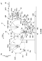
- FIG. 1A is a schematic side view of a production line LM for a disposable diaper 1 as an example of an absorbent article
- FIG. 1B is a schematic plan view of the line LM indicated by arrows BB in FIG. 1A. It is IV-IV arrow line view in FIG. 1B
- FIG. 2B is a schematic plan view taken along the line BB in FIG. 2A. It is the figure which represented typically the mode of the material 3 at the time of cutting the preceding material 3a. It is the figure which represented typically the mode of the material 3 at the time of the belt member 26F returning to a standby position.
- FIG. 1A is a schematic side view of a production line LM for a disposable diaper 1 as an example of an absorbent article
- FIG. 1B is a schematic plan view of the line LM indicated by arrows BB in FIG. 1A. It is IV-IV arrow line view in FIG. 1B
- FIG. 2B is a schematic plan view taken along the line BB in FIG. 2A
- FIG. 6 is a diagram illustrating positions P1 to P7 of the material 3 on the conveyance path and path lengths L12 to L67 of the material 3 between positions. It is a 1st explanatory view for explaining superiority (action effect) of this embodiment. It is a 2nd explanatory view for explaining superiority (action effect) of this embodiment. It is a 3rd explanatory view for explaining predominance (action effect) of this embodiment. It is the 4th explanatory view for explaining superiority (action effect) of this embodiment. It is a 5th explanatory view for explaining superiority (action effect) of this embodiment. It is a 6th explanatory view for explaining predominance (action effect) of this embodiment. It is the figure which showed the 1st modification concerning a press mechanism. It is the figure which showed the 2nd modification concerning a press mechanism.
- the path length of the material from the downstream end of the material transfer portion passed over the inlet roll to the upstream end of the material transfer portion over the moving roll when positioned at the reference position is characterized in that the preceding material is cut so that the total length of the joining portion and the overlapping portion becomes longer.
- Such a material splicing method When forming the fin portion, The path length of the material from the downstream end of the material transfer portion passed over the inlet roll to the downstream end of the material transfer portion over the moving roll when located at the reference position It is preferable to cut the preceding material so that the length of the overlapping portion becomes longer.
- Such a material splicing method The material is transported in the transport direction in a state where the material is stretched over the entrance roll, the moving roll, and the exit roll of the dancer unit, After connecting the succeeding material to the preceding material, the material is provided to transport the material provided so that the joining portion and the overlapping portion are aligned along the transport direction, and the material is the entrance roll, the moving roll.
- Such a material splicing method When forming the fin portion, The downstream end of the material passing portion that is passed to the outlet roll via the moving roll when located at the reference position from the downstream end of the material passing portion that is passed to the inlet roll It is desirable to cut the preceding material so that the length of the overlapping portion is longer than the path length of the material up to.
- Such a material splicing method The material is transported in the transport direction in a state where the material is stretched over the entrance roll, the moving roll, and the exit roll of the dancer unit, After connecting the succeeding material to the preceding material, the material is provided to transport the material provided so that the joining portion and the overlapping portion are aligned along the transport direction, and the material is the entrance roll, the moving roll.
- Such a material splicing method When forming the fin portion, The path length of the material from the upstream end of the material transfer portion passed over the inlet roll to the upstream end of the material transfer portion over the moving roll when located at the reference position It is preferable to cut the preceding material so that the total length of the joint and the overlapping portion becomes longer.
- Such a material splicing method When joining the succeeding material to the preceding material to be transported, the contact member is moved from a standby position to a contact position contacting the preceding material, and the preceding material is pressed against the succeeding material, After the joint portion of the material to be conveyed has reached the moving roll, the contact member is returned from the contact position to the standby position, When forming the fin portion, From the path length of the material from the downstream end of the contact portion of the material that contacts the contact member to the upstream end of the transfer portion of the material that is stretched over the moving roll when positioned at the reference position However, it is desirable to cut the preceding material so that the total length of the joint and the overlapped portion becomes longer.
- Such a material splicing method After the joint portion of the material to be conveyed has passed the moving roll, the contact member is returned from the contact position to the standby position, When forming the fin portion, From the path length of the material from the downstream end of the contact portion of the material that contacts the contact member to the downstream end of the transfer portion of the material that is stretched over the moving roll when positioned at the reference position However, it is desirable to cut the preceding material so that the length of the overlapping portion becomes longer.
- Such a material splicing method When joining the succeeding material to the preceding material to be transported, the contact member is moved from a standby position to a contact position contacting the preceding material, and the preceding material is pressed against the succeeding material, When forming the fin portion, From the path length of the material from the downstream end of the contact portion of the material that contacts the contact member to the upstream end of the transfer portion of the material that is stretched over the moving roll when positioned at the reference position However, it is desirable to cut the preceding material so that the total length of the joining portion and the overlapping portion is shortened.
- Such a material splicing method When joining the succeeding material to the preceding material to be transported, the contact member is moved from a standby position to a contact position contacting the preceding material, and the preceding material is pressed against the succeeding material, It is desirable to cut the preceding material in a state where the contact member is located at the contact position.
- Such a material splicing method When joining the succeeding material to the preceding material to be transported, the contact member is moved from a standby position to a contact position contacting the preceding material, and the preceding material is pressed against the succeeding material,
- the contact member is preferably a rotatable belt member.
- the belt member rotates when the first rotation roller and the second rotation roller rotate in a state of being stretched between the first rotation roller and the second rotation roller, and the central axis of the first rotation roller It is desirable that the member moves from the standby position to the contact position by swinging around the swing axis.
- the material is a continuous sheet of a fiber assembly in which the fiber density on one side is higher than that on the other side,
- a contact member is moved from a standby position to a contact position contacting the one surface of the preceding material, and the preceding material and the following material are moved. It is desirable to press the preceding material against the succeeding material in a state where an adhesive member is sandwiched between the material and the material.
- the material is a continuous sheet of a fiber assembly in which the fiber density on one side is higher than that on the other side, When forming the fin portion by cutting the preceding material, it is desirable to insert a cutter blade from the one surface side.
- a dancer unit having an entrance roll and a moving roll;
- a transport unit that transports the material in the transport direction in a state where the material related to the absorbent article is stretched over the inlet roll and the moving roll;
- a material joint that joins the preceding material to the preceding material by joining the leading material of the following material as the preceding material to be conveyed, and the preceding material; Cutting the preceding material at a position upstream of the joining portion of the preceding material and the succeeding material in the transport direction, and forming a fin portion of the preceding material upstream of the joining portion; and
- the conveyance unit is configured to convey the material provided such that the joining portion, the fin portion, and the overlapping portion where the succeeding material overlaps are arranged along the conveyance direction, and the material includes the inlet roll and the Continue on the moving roll,
- a control unit that controls conveyance of the material so that the moving roll is located at a reference position;
- the cut portion extends from the downstream end of the material transfer portion extended over the inlet roll
- FIG. 1A is a schematic side view of an absorbent article production line LM
- FIG. 1B is a schematic plan view of the line LM indicated by arrows BB in FIG. 1A.
- the thing which should be visible may be abbreviate
- a disposable diaper 1 is produced as an example of an absorbent article.
- a plurality of continuous sheets 3, 3... for example, a plurality of soft and flexible continuous sheets 3 such as non-woven fabric and tissue are used.
- a material coil 3C formed by winding the continuous sheet 3 as a material around the paper tube 3p (FIG. 2A) in a coil shape.
- the fiber density of the front surface is higher than the fiber density of a back surface (equivalent to the other side). Then, the continuous sheet 3 is wound around the material coil 3C so that the front surface becomes the outer peripheral surface of the material coil 3C and the back surface becomes the inner peripheral surface of the material coil 3C.
- the various material coils 3C, 3C,... are mounted on the material supply device 10 provided in the production line LM for each material 3 type, and each material 3 is fed out.
- Each material 3 is subjected to processing such as pressing and cutting by various processing units 110, 110... (Processing device) while being transported along a predetermined transport path in the production line LM.
- the disposable diaper 1 is finally produced by polymerization with the material 3 and the appropriate member 2.
- Examples of the processing unit 110 include a fiber stacking device 110a, a cutting device 110b, a pressing device 110c, a leg hole cutting device 110d, and an end cutting device 110e, but are not limited thereto.
- each apparatus 110a, 110b, 110c, 110d, 110e has the following functions, for example.
- the fiber stacking device 110a generates the absorbent body 2 as the above-mentioned member using, as a main material, liquid absorbent fibers such as pulp fibers.
- the cutting device 110b cuts the material 3 into a single sheet to generate a leakage preventing sheet 3s, and conveys the leakage preventing sheets 3s, 3s adjacent to each other in the conveying direction with a gap therebetween.
- seat 3s is joined to another material 3 in the state which opened this space
- a known slip cutting device for example, Japanese Patent Application Laid-Open No. 2011-083547
- the pressing device 110c presses the materials 3, 3... With a pair of upper and lower rolls.
- the leg hole cutting device 110d forms leg openings in the materials 3, 3... By a pair of upper and lower rolls.
- the end cut device 110e generates the disposable diaper 1 by separating the disposable diaper 1 from the materials 3, 3.
- X direction three directions orthogonal to each other in the production line LM are referred to as an X direction, a Y direction, and a Z direction, respectively.
- the X direction and the Y direction are each oriented in the horizontal direction, but as shown in FIG. 1A, the Z direction is oriented in the vertical direction.
- the X direction and the Y direction are orthogonal to each other.
- various processing units 110, 110,... are arranged side by side along the X direction.
- the material 3 is transported along the X direction in plan view between the processing units 110, 110.
- each material supply device 10 is moved from the processing units 110, 110. It is arranged at a shifted position. Therefore, the supply of the material 3 from each material supply apparatus 10 to the processing units 110, 110... Is mainly performed along the Y direction. That is, after the material 3 fed out in the Y direction in the material supply apparatus 10 is transported along the Y direction, the processing unit 110, 110 is supplied with the material 3.
- the material supply device 10 is provided corresponding to each type of the material 3, but the basic configuration of each material supply device 10, 10... Is the same. Therefore, below, the one material supply apparatus 10 is demonstrated.
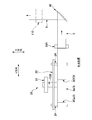
- FIG. 2A is a view taken along arrow IV-IV in FIG. 1B.
- FIG. 2B is a schematic plan view taken along the line BB in FIG. 2A. 2A and 2B, the members are appropriately omitted for the purpose of preventing the complication of the drawings.
- the material supply device 10 has a material splicing device 20. Then, the material splicing device 20 uses the material 3f of another material coil 3Cf that has not been fed out as the succeeding material 3f with respect to the preceding material 3a before the preceding material 3a being fed out from the material coil 3Ca disappears. Thus, the material 3 (3a, 3f) is continuously supplied to the processing unit 110 of the production line LM without interruption. Further, a storage device 40 for storing the material 3 (3a, 3f) sent from the material splicing device 20 in the form of a loop 3L is provided at a position downstream of the material splicing device 20 in the transport direction. .
- a turn bar 50 is provided as a transport direction changing member on the downstream side of the storage device 40 in the transport direction.
- the turn bar 50 changes the conveyance direction of the material 3 from the Y direction to the X direction.
- the material 3 is sent to the processing unit 110 with the conveyance direction changed to the X direction.
- the material splicing device 20 has a support plate 21 such as a so-called end plate standing on the floor LMB of the production line LM, and a band plate shape supported by the support plate 21 so as to be turnable about a turning axis C22 along the X direction.
- Each of the unillustrated servo motors that independently drive and rotate the two feeding rotary shafts 24 and 24 and the preceding material 3a being fed by one feeding rotating shaft 24 are supported by the other feeding rotating shaft 24.
- a press mechanism 26 (corresponding to a material joint) that presses against the outer peripheral surface 3Cfs (that is, the front surface) of the succeeding material coil 3Cf and joins the succeeding material 3f;
- The has a leading material coil 3Ca of the cutter mechanism 28 to separate from the paper pipe 3p (corresponding to the cut portion), and a controller (not shown) of the computer or a sequencer for controlling them.
- the two feeding rotary shafts 24, 24 are provided point-symmetrically with respect to the turning axis C22 of the turret 22. Therefore, by turning the turret 22 around the turning axis C22, the positions of each other can be switched. Further, both of the feeding rotating shafts 24, 24 can be supported by being inserted into the central paper tube 3p of the material coil 3C. In the state where the insertion is supported, the feeding rotary shaft 24 is driven to rotate, thereby feeding the material 3 from the material coil 3C.
- the two feeding rotary shafts 24, 24 basically perform this feeding operation alternately. That is, while the one feeding rotary shaft 24 feeds the material 3a from the material coil 3Ca, the other feeding rotary shaft 24 is in a standby state which is a non-feeding state. When the material 3a of one of the feeding rotating shafts 24 is almost gone, the material 3f of the material coil 3Cf of the unrolled state attached to the other feeding rotating shaft 24 while using the material 3a as the preceding material 3a. These materials 3a and 3f are joined together as a subsequent material 3f. Therefore, thereafter, the other feeding rotary shaft 24 feeds and supplies the material 3f from the succeeding material coil 3Cf.
- the succeeding material coil position P3Cf where the succeeding material coil 3Cf that is in the undrawn state in the joining process is to be positioned, and the joining process.
- the preceding material coil position P3Ca where the preceding material coil 3Ca in the extended state should be positioned is set.
- the former succeeding material coil position P3Cf and the latter preceding material coil position P3Ca are set on both sides in the Y direction, and the height in the vertical direction (Z direction) is the same height. There is no limitation to this.
- the feeding rotary shaft 24 rotates counterclockwise, so that the material coils 3Ca and 3Cf feed the materials 3a and 3f from below. Therefore, a conveyance path for the material 3a fed from the preceding material coil 3Ca is set below the subsequent material coil 3Cf located at the subsequent material coil position P3Cf, and further below this conveyance path, A press mechanism 26 and a cutter mechanism 28 are arranged.
- the press mechanism 26 includes a first fixed shaft 26A along the X direction, a first rotating roller 26B that rotates about the first fixed shaft 26A, and a swing arm 26C that swings about the first fixed shaft 26A.
- the second fixed shaft 26D provided at the end of the swing arm 26C opposite to the first fixed shaft 26A, the second rotating roller 26E rotating around the second fixed shaft 26D, and the first rotating roller 26B
- a rotatable endless belt member 26F (corresponding to a contact member) stretched around the second rotating roller 26E
- an actuator 26G such as an air cylinder that swings the swing arm 26C (belt member 26F)
- a drive source such as a servo motor (not shown) that drives the one rotation roller 26B or the second rotation roller 26E (in the present embodiment, the first rotation roller 26B) is provided.
- the belt member 26F positioned at the standby position is moved to a contact position where the preceding material 3a contacts the preceding material 3a, so that the preceding material 3a becomes the following material 3f. Press.
- the actuator 26G drives the swing arm 26C
- the swing arm 26C swings.
- the second fixed shaft 26D and the second rotating roller 26E supported by the second fixed shaft 26D move toward the preceding material 3a.
- the belt member 26F also moves toward the preceding material 3a by the said movement of the 2nd rotation roller 26E, and the belt member 26F contacts the preceding material 3a before long.
- the belt member 26F moves from the standby position to the contact position by swinging with the central axis (that is, the first fixed shaft 26A) of the first rotating roller 26B as the swing axis.
- the belt member 26F when the belt member 26F is moved from the standby position to the contact position, the preceding material 3a is conveyed (described in detail later), and therefore when the belt member 26F contacts the preceding material 3a. Control is performed such that the belt member 26F is rotated at the same speed as that of the preceding material 3a so that the preceding material 3a and the belt member 26F can be rotated. That is, when the belt member 26F moves from the standby position to the contact position, the first rotation roller 26B is driven by the first rotation roller 26B by driving the first rotation roller 26B. The belt member 26F is rotated in cooperation with the second rotating roller 26E. That is, the belt member 26F rotates when the first rotating roller 26B and the second rotating roller 26E rotate while being stretched over the first rotating roller 26B and the second rotating roller 26E.
- the actuator 26G swings the swing arm 26C (belt member 26F) in the reverse direction to return the belt member 26F from the contact position to the standby position, and the drive source is the belt member 26F. Stop rotation.
- the first rotating roller 26B or the second rotating roller 26E is used as a driving roller, and the belt member 26F is driven and rotated.
- the present invention is not limited to this, and the first rotating roller 26B and the second rotating roller 26E may be driven rollers, and the belt member 26F may obtain a rotational force by contact with the material 3.
- the cutter mechanism 28 drives an arm member 28A supported so as to be swingable about a rotation axis C28A along the X direction, a cutter blade 28B fixed to the swing end of the arm member 28A, and the arm member 28A. And an actuator 28C such as an air cylinder.
- the cutter blade 28B at the standby position approaches and contacts the preceding material 3a from below, thereby cutting the preceding material 3a.
- the preceding material 3a joined to the succeeding material 3f is separated from the paper tube 3p of the feeding rotating shaft 24.
- the cutting position at which the preceding material 3a is cut is located on the upstream side in the transport direction with respect to the contact portion with which the belt member 26F contacts. Further, when cutting, the cutter blade 28B is inserted from the aforementioned front surface (that is, the surface having the higher fiber density) side of the preceding material 3a, so that the back surface (the surface having the lower fiber density). ) Compared to the case of entering from the side, it is possible to easily cut the preceding material 3a (easy to cut the preceding material 3a).
- the accumulating device 40 is a so-called dancer unit that accumulates the material 3 fed from the material splicing device 20 in the form of a loop 3L so that the material 3 can be sent to the turn bar 50. Then, by adjusting the size of the loop 3L, the tension variation of the material 3 is absorbed / suppressed (the tension of the material 3 is controlled), and the material 3 in which the tension variation is suppressed is sent to the turn bar 50. To do.
- the storage device 40 having such a function is rotatably supported at a fixed position, and has an inlet roll 41u and an outlet roll 41d positioned at the inlet and outlet of the storage device 40, and a predetermined direction (substantially Y) that can change the size of the loop 3L.
- a predetermined direction substantially Y
- Direction an arm member supported so as to be swingable about a rotation axis C41A along the X direction so as to guide the movement roll 41m so as to reciprocate in the predetermined direction. 41A.
- the inlet roll 41u, the moving roll 41m, and the outlet roll 41d are supported so as to be rotatable around rotation axes C41u, C41m, and C41d along the X direction.
- the material 3 is laid on each roll in the order of the inlet roll 41u, the moving roll 41m, and the outlet roll 41d in the conveyance direction, whereby the loop 3L of the material 3 is formed. ing.
- a predetermined load (N) is applied to the moving roll 41m from the actuator 41C such as an air cylinder via the arm member 41A in the direction of increasing the loop 3L. Therefore, when the tension (N) of the material 3 is smaller than a predetermined value based on the predetermined load, the moving roll 41m moves so that the loop 3L becomes large, but the tension (N) of the material 3 is the predetermined value. If larger, the moving roll 41m moves so that the loop 3L becomes smaller.
- the size of the loop 3L is measured by an appropriate sensor (not shown) such as a linear encoder or a rotary encoder, and this measurement signal is transmitted to a controller (corresponding to a control unit). Therefore, the controller, based on the measurement signal, instructs the rotation speeds 24 and 24 of the feeding splicing device 20 so that the size of the loop 3L, in other words, the position of the moving roll 41m is constant. (Rpm) is corrected, and as a result, the tension (tension) of the material 3 is appropriately controlled (tension fluctuation is suppressed). That is, the controller controls the conveyance of the material 3 so that the moving roll 41m is located at a predetermined position (hereinafter referred to as a reference position), so that the size of the loop 3L does not vary.
- a reference position a predetermined position
- the middle position of the three moving rolls 41m shown in FIG. 2A is set as the reference position, and the position where the size of the loop 3L is maximum (minimum) is set to the other two positions.
- various correction methods can be used for the correction processing of the command rotational speed.
- the following process may be repeated at a predetermined control cycle.
- the actual value of the size of the current loop 3L is obtained based on the measurement signal of the sensor, and the deviation amount is obtained by subtracting the target value of the size of the loop 3L from the actual value.
- the control amount is calculated by multiplying the deviation amount by a predetermined control gain, and the control amount is subtracted from the above-mentioned designated rotational speed (rpm), and the subtracted value is fed out as a corrected command rotational speed.
- the servo motor of the rotary shaft 24 is controlled.
- the correction process is performed not only on the feeding rotary shaft 24 that feeds the preceding material 3a, but also on the feeding rotating shaft 24 that feeds the following material 3f, at least the preceding material of the following material 3f. It is made after joining to 3a (after joining), and preferably, just before joining or from the start of the rotational operation of the rotary shaft 24.
- the tension fluctuation can be reliably suppressed from the first turn (first turn) of the outer periphery of the succeeding material coil 3Cf.
- the inlet roll 41u is a driven roll that rotates with the rotation of the material 3, but the outlet roll 41d may also be a driven roll or driven from a drive source such as a servo motor. It is good also as a drive roll which obtains a rotational force and rotates.
- the exit roll 41d is a driven roll
- the transport roll 29R (corresponding to the transport unit) adjacent downstream in the transport direction of the exit roll 41d is a drive roll. Accordingly, in the present embodiment, the transport roll 29R and the feeding rotary shaft 24 cooperate to receive the driving force from the servo motor and transport the material 3 in the transport direction.
- the turn bar 50 changes the conveyance direction of the material 3 sent from the storage device 40 from the Y direction to the X direction and sends the material 3 to the processing unit 110.
- the turn bar 50 is a round bar having a predetermined diameter such as a stainless steel polishing bar. That is, as shown in FIG. 2B, the longitudinal direction of the round bar 50 is arranged so as to be immovable and non-rotatable while facing the same angle of 45 ° from both the X and Y directions. Yes. Therefore, when the material 3 is wound around the turn bar 50, the conveyance direction of the material 3 is changed by 90 ° from the Y direction to the X direction.
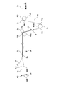
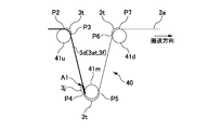
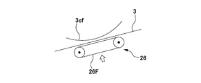
- FIG. 3 is a diagram schematically showing the state of the material 3 when the preceding material 3a is cut.
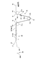
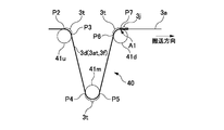
- FIG. 4 is a diagram schematically illustrating the state of the material 3 when the belt member 26F returns to the standby position.
- the material 3 is stretched over each roll (inlet roll 41u, moving roll 41m, outlet roll 41d, transport roll 29R, etc.), and the transport section (transport roll 29R and feeding rotary shaft). 24).
- the front end 3fe of the material 3f located on the outer peripheral surface 3Cfs of the succeeding material coil 3Cf has already been provided with a double-sided tape 4j (corresponding to an adhesive member) for joining.
- a double-sided tape 4k for temporary fixing is provided so that the tip portion 3fe is not separated from the material coil 3Cf.
- the controller determines that the remaining amount of the material 3a of the preceding material coil 3Ca has become equal to or less than the specified value, the controller starts the material splicing process. That is, the process of joining the trailing material 3f to the preceding material 3a by joining the leading end 3fe of the following material 3f to the preceding material 3a with the conveyed material 3 as the preceding material 3a is started.
- the controller controls the feeding rotary shaft 24 to start the rotation of the trailing material coil 3Cf, and continues until the feeding speed value of the following material 3f becomes the same speed as the feeding speed value of the preceding material 3a.
- the coil 3Cf is accelerated.
- the controller controls the actuator 26G of the press mechanism 26 to move the belt member 26F from the standby position to the contact position. That is, the press mechanism 26 moves the belt member 26F from the standby position to the contact position, and presses the preceding material 3a against the following material 3f.
- the leading end 3fe of the succeeding material coil 3Cf passes through the belt member 26F, and thereby the leading end 3fe is joined to the preceding material 3a by the double-sided tape 4j. That is, when the preceding material 3a is pressed against the succeeding material 3f with the double-sided tape 4j sandwiched between the preceding material 3a and the following material 3f, the preceding material 3a and the following material 3f perform the feeding operation. It will be joined without stopping.
- the belt member 26F when joining the succeeding material 3f to the preceding material 3a to be transported, from the standby position to the front surface of the preceding material 3a (that is, the surface having the higher fiber density).
- the belt member 26F is moved to the contact position where it comes into contact, and the preceding material 3a is pressed against the succeeding material 3f with the double-sided tape 4j sandwiched between the preceding material 3a and the following material 3f. That is, the belt member 26 ⁇ / b> F contacts the front surface of the fiber having a higher fiber density rather than the back surface having the lower fiber density.
- the adhesive of the double-sided tape 4j located on the back side of the preceding material 3a has entered (penetrated) the preceding material 3a, the adhesive passes through the preceding material 3a and the belt member 26F.
- the phenomenon of adhering to the surface can be suppressed by blocking the pressure-sensitive adhesive on the front surface side of the high fiber density portion.
- the portion (front surface) in contact with the belt member 26F has a high fiber density portion (in other words, the fibers are compressed to a high density).
- the portion of the belt member 26F is less likely to adhere to the preceding material 3a than the low fiber density portion (in other words, the portion where the fibers are not so compressed and soft).
- the preceding material 3a and the succeeding material 3f are integrally transported by the transport unit (the transport roll 29R and the feeding rotary shafts 24 and 24).
- the joint 3j between the preceding material 3a and the succeeding material 3f also moves in the transport direction.
- the controller controls the actuator 26G of the cutter mechanism 28 at a predetermined timing to perform the cutting process for the preceding material 3a. That is, when the cutter blade 28B of the cutter mechanism 28 contacts the preceding material 3a, the preceding material 3a is cut.
- the preceding material 3a (denoted by reference numeral A2 in FIG. 3) at a position upstream of the joint portion 3j between the preceding material 3a and the following material 3f in the transport direction. Cut the indicated position). That is, for the purpose of connecting the succeeding material 3f to the preceding material 3a, the position at which the preceding material 3a is cut may be the rear end (the position indicated by reference numeral A1 in FIG. 3). In this case, the preceding material 3a is cut at a position on the rear side for another purpose (detailed later).
- the tail-shaped preceding material 3a portion extending from the joint portion 3j (the portion from the reference symbol A1 to the reference symbol A2 in FIG. 3. 3at) is formed.
- the cut timing is determined so that the length of the fin portion 3at becomes a predetermined length. As can be understood from FIG. Is considerably after the joining timing (after the joining part 3j exceeds the inlet roll 41u).
- the cutter mechanism 28 cuts the preceding material 3a at a position upstream of the joining portion 3j between the preceding material 3a and the following material 3f in the conveying direction, and the fin of the preceding material 3a is cut.
- the portion 3at is formed on the upstream side of the joint portion 3j.
- the controller stops the rotation of the rotating shaft 24 by reducing the rotation speed of the feeding rotating shaft 24 at the preceding material coil position P3Ca.
- the controller controls the actuator 26G of the press mechanism 26 to move (return) the belt member 26F from the contact position to the standby position. That is, in the present embodiment, the cutter mechanism 28 cuts the preceding material 3a while the belt member 26F is located at the contact position, and after the cutting of the preceding material 3a is completed, the belt member 26F moves to the standby position. Returned. That is, as soon as the succeeding material 3f is joined to the preceding material 3a, the belt member 26F is not returned to the standby position, but the cutting process of the preceding material 3a is waited, and then the returning process is executed.
- the belt member 26F is returned from the contact position to the standby position. That is, after the rear end (indicated by reference symbol A2) of the fin portion 3at passes through the belt member 26F (in other words, the downstream end P1 of the contact portion 3b of the material 3 that contacts the belt member 26F), the belt member 26F. Is moved to the standby position.
- the conveyance of the material 3 by the conveyance unit (the conveyance roll 29R and the feeding rotary shaft 24) is continued.
- the preceding material 3a preceding material alone part
- the joining part 3j the fin part 3at
- the overlapping part 3d is the fin part 3at
- 4 is overlapped with the succeeding material 3f from the reference A1 to the reference symbol A2 in Fig. 4.
- the length of the overlapping portion 3d is the same as the length of the fin portion 3at), the following material 3f (rear In the state where the row materials alone are arranged in this order, each moves in the transport direction. That is, the transport unit (the transport roll 29R and the feeding rotary shaft 24) transports the material 3 provided so that the joining portion 3j and the overlapping portion 3d are arranged in the transport direction. It will continue in the state of being passed over the entrance roll 41u, the moving roll 41m, the exit roll 41d, the transport roll 29R, etc. (the joining portion 3j and the overlapping portion 3d will eventually move to the respective rolls by moving in the transport direction). In order).
- the operator removes the paper tube 3p of the preceding material 3a from the feeding rotating shaft 24 and the feeding rotating shaft 24.
- a new material coil 3Cn that has not been fed out is inserted and attached.
- the tip 3ne of the material 3n located on the outer peripheral surface 3Cns of the new material coil 3Cn is provided with the above-mentioned double-sided tape 4j for bonding, and the double-sided tape 4k for temporary fixing is provided on the back surface. .
- the controller determines that the conditions for turning the turret 22 are satisfied, that is, the outer diameter of the succeeding material coil 3Cf located at the succeeding material coil position P3Cf is reduced by the feeding, and the coil 3Cf is manufactured on the production line.
- the controller determines that the turret 22 can turn without interference with the floor portion LMB of the LM, the belt member 26F at the standby position, the cutter blade 28B at the standby position, etc.
- the controller controls the servo motor of the turret 22 Turn the turret 22 clockwise. As a result, the subsequent material coil 3Cf is moved downward along the circular arc trajectory and then moved upward.
- the material coil 3Cf is moved to the preceding material coil position P3Ca and the undrawn state described above.
- the new material coil 3Cn is moved to the subsequent material coil position P3Cf. Then, when the timing of the next joining process comes, the controller repeats the above joining process.
- tension control for suppressing fluctuations in tension is performed during the joining process (material splicing process). More specifically, the tension control described above is always executed from before the material splicing process starts, through the material splicing process (belt member pressing process), the cut process, the belt member return process, and after the belt member return process. .
- the controller adjusts the rotational speed of the feeding rotary shafts 24 and 24 in the transport unit (the transport roll 29R and the feeding rotary shafts 24 and 24), and the moving roll 41m is moved to the reference position.
- the conveyance of the material 3 is controlled so as to be positioned at (so that the size of the loop 3L becomes a constant value). Therefore, even if a tension fluctuation temporarily occurs due to various factors (referred to as an unsteady state for the sake of convenience), the control immediately returns to a normal state (referred to as a steady state for the sake of convenience).
- the leading portion 3at is formed following the joining portion 3j. Cut material 3a. And it cuts so that the length of fin part 3at may become predetermined length.
- the length of the fin portion 3 at (in other words, the length of the overlapping portion 3 d) when the fin portion 3 at is formed will be described. explain. And what kind of predominance will arise when the length of fin part 3at (overlapping part 3d) is made into the length concerned is explained.
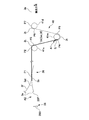
- FIG. 5 is a diagram corresponding to FIG. 3 and shows the positions P1 to P7 of the material 3 in the transport path and the path lengths (length of the transport path) L12 to L67 of the material 3 between the positions.
- 6 to 11 are diagrams corresponding to FIG. 3 and are explanatory diagrams for explaining the superiority (action and effect) of the present embodiment. 5 to 11, the moving roll 41m is located at the reference position.
- the total length of the joining portion 3j and the overlapping portion 3d (fin portion 3at) is located at the reference position from the downstream end P3 of the spanning portion 3t of the material 3 spanned on the inlet roll 41u. It is larger than the path length (L34) of the material 3 up to the upstream end P4 of the transfer part 3t of the material 3 passed over the moving roll 41m. That is, in the cutter mechanism 28 (cutter blade 28B), the total length of the joining portion 3j and the overlapping portion 3d (fin portion 3at) is longer than the path length (L34) of the material 3 from the downstream end P3 to the upstream end P4. The preceding material 3a is cut so as to be longer. This gives rise to the following advantages:
- the total length of the joining portion 3j and the overlapping portion 3d (fin portion 3at) is determined from the path length (L34) from the downstream end P3 to the upstream end P4. Therefore, in this situation, the state where the overlapping portion 3d is stretched over the inlet roll 41u is ensured, and the double portion (joint portion 3j or overlapping portion 3d) of the material 3 extends from the upstream end P4 to the downstream end P3. The part that is not the material alone). Therefore, even if an impact is applied to the material 3 in the above situation, it is possible to suppress fluttering (roughness) of the material 3 with the high rigidity of the double portion, and it is also possible to suppress fluctuations in the tension of the material 3. Become.
- the total length of the joining portion 3j and the overlapping portion 3d (fin portion 3at) is set to the reference position from the downstream end P3 of the spanning portion 3t of the material 3 spanned on the inlet roll 41u. It is longer than the path length (L34 + L45 + L56) of the material 3 up to the upstream end P6 of the transfer part 3t of the material 3 that is passed through the exit roll 41d via the moving roll 41m when positioned.
- the cutter mechanism 28 (cutter blade 28B) has a total length of the joining portion 3j and the overlapping portion 3d (fin portion 3at) rather than the path length (L34 + L45 + L56) of the material 3 from the downstream end P3 to the upstream end P6.
- the preceding material 3a is cut so as to be longer.
- the fluttering (rambling) of the material 3 due to the following (also referred to as an impact on the outlet roll 41d) can be suppressed. Therefore, the fluttering (roughness) of the material 3 can be more appropriately suppressed, and the tension fluctuation of the material 3 can be more appropriately suppressed.
- the length of the fin portion 3at is set as described above, the material 3 flutters due to the impact on the exit roll 41d as well as the material 3 flutters due to the impact on the moving roll 41m. Although it has an advantage in suppressing (ramp), the length of the fin portion 3at is remarkably increased instead.
- the preceding material 3a is cut so that the length of the overlapping portion 3d (fin portion 3at) is longer than the path length (L34 + L45) of the material 3 from the downstream end P3 to the downstream end P5.
- the length of the fin portion 3at can be further increased as follows.
- the length of the overlapping portion 3d (fin portion 3at) is the exit from the downstream end P3 of the delivery portion 3t of the material 3 passed over the entrance roll 41u via the moving roll 41m when positioned at the reference position. It is made longer than the path length (L34 + L45 + L56 + L67) of the material 3 up to the downstream end P7 of the transfer part 3t of the material 3 passed over the roll 41d.
- the cutter mechanism 28 (cutter blade 28B) is configured such that the length of the overlapping portion 3d (fin portion 3at) is longer than the path length (L34 + L45 + L56 + L67) of the material 3 from the downstream end P3 to the downstream end P7.
- the preceding material 3a is cut.
- the joining portion 3j reaches the outlet roll 41d, but also from when the joining portion 3j reaches the outlet roll 41d (see FIG. 8) until the joining portion 3j passes through the outlet roll 41d (see FIG. 9).
- the state where the overlapping portion 3d is stretched over the inlet roll 41u is ensured, and the double portion (joint portion 3j) between the upstream end P6 and the downstream end P3 (that is, all the loops 3L of the storage device 40) is formed.
- the overlapping portion 3d is not a single material) (see FIGS. 8 and 9). Therefore, the fluttering (rambling) of the material 3 can be more appropriately suppressed, and the tension fluctuation of the material 3 can be more appropriately suppressed.
- the total length of the joining portion 3j and the overlapping portion 3d (fin portion 3at) is set to the reference position from the upstream end P2 of the spanning portion 3t of the material 3 spanned on the inlet roll 41u. It is longer than the path length (L23 + L34) of the material 3 to the upstream end P4 of the transfer part 3t of the material 3 that is passed over the moving roll 41m when it is positioned. That is, in the cutter mechanism 28 (cutter blade 28B), the total length of the joining portion 3j and the overlapping portion 3d (fin portion 3at) is larger than the path length (L23 + L34) of the material 3 from the upstream end P2 to the upstream end P4. The preceding material 3a is cut so as to be longer.
- the overlapping portion 3d contacts not only a part of the inlet roll 41u but also the material 3 in the inlet roll 41u. A state of being stretched over the entire portion to be obtained is ensured. That is, since the portion from the upstream end P4 to the upstream end P2 is a double portion of the material 3 (a portion that is not the material alone of the joint portion 3j or the overlapping portion 3d), even if an impact is applied to the material 3 in the above situation The flapping (roughness) of the material 3 can be more appropriately suppressed by the high rigidity of the double portion firmly stretched over the entrance roll 41u, and the tension fluctuation of the material 3 can be suppressed more appropriately. It becomes possible.
- the total length of the joining portion 3j and the overlapping portion 3d (fin portion 3at) is located at the reference position from the downstream end P1 of the contact portion 3b of the material 3 that contacts the belt member 26F. It is longer than the path length (L12 + L23 + L34) of the material 3 up to the upstream end P4 of the transfer part 3t of the material 3 passed over the moving roll 41m. That is, the cutter mechanism 28 (cutter blade 28B) has a total length of the joining portion 3j and the overlapping portion 3d (fin portion 3at) rather than the path length (L12 + L23 + L34) of the material 3 from the downstream end P1 to the upstream end P4. The preceding material 3a is cut so as to be longer. Further, after the joining portion 3j of the material 3 to be conveyed reaches the moving roll 41m, the belt member 26F is returned from the contact position to the standby position.
- the length of the fin portion 3at is set as described above, the fluttering of the material 3 is more appropriately suppressed by the high rigidity of the double portion applied to the inlet roll 41u and the belt member 26F.
- the length of the fin portion 3at is remarkably increased instead.
- the total length of the joint portion 3j and the overlapping portion 3d (fin portion 3at) is longer than the path length (L23 + L34) of the material 3 from the upstream end P2 to the upstream end P4.
- the total length of the joint portion 3j and the overlapping portion 3d (fin portion 3at) is shorter than the path length (L12 + L23 + L34) of the material 3 from the downstream end P1 to the upstream end P4.
- the length of the fin portion 3at can be further increased as follows. That is, the material 3 stretched over the moving roll 41m when the length of the overlap portion 3d (fin portion 3at) is located at the reference position from the downstream end P1 of the contact portion 3b of the material 3 that contacts the belt member 26F. It is made longer than the path length (L12 + L23 + L34 + L45) of the material 3 to the downstream end P5 of the transfer part 3t. That is, the cutter mechanism 28 (cutter blade 28B) is configured such that the length of the overlapping portion 3d (fin portion 3at) is longer than the path length (L12 + L23 + L34 + L45) of the material 3 from the downstream end P1 to the downstream end P5. The preceding material 3a is cut. Further, after the joint portion 3j of the material 3 to be conveyed passes the moving roll 41m, the belt member 26F is returned from the contact position to the standby position.
- various methods can be used to determine the cut timing in order to set the length of the overlapping portion 3d (fin portion 3at) to a predetermined length.
- the rotational speed of the material coil 3C (or the feeding rotary shafts 24, 24) is adjusted with a rotary encoder, and the outer diameter of the material coil 3C is decreased with a laser displacement meter, an ultrasonic displacement meter, etc. It is possible to constantly monitor and to determine the feeding speed value of the material 3 (which can change from moment to moment) from both values. Then, the material 3 may be cut at a timing when the integrated value of the feeding speed value in the elapsed time after the joining (after the joining portion 3j is formed) becomes equal to the predetermined length (desired length).
- a sensor CCD camera or the like that can detect the joint 3j is installed at a predetermined position on the conveyance path, and a predetermined time elapses after detection of the joint 3j (or after detection). It is also possible to take measures to cut the material 3 (at the same timing).
- the total length of the joint portion 3j and the overlapping portion 3d (fin portion 3at) or the length of the overlapping portion 3d (fin portion 3at) is longer than the length between the positions P1 to P7 (or (Since it is not strictly required to cut to be exactly equal to the length between positions P1 to P7), the cut timing is determined with a margin. do it.
- the moving roll 41m is used as the reference.
- the moving roll 41m What is necessary is just to determine the cut timing by further satisfying the margin by the length of the difference from the position at the reference position.
- the so-called unfolded disposable diaper 1 is illustrated as an example of the absorbent article, but the present invention is not limited thereto.
- a pants-type disposable diaper may be used.
- the absorbent article is not limited to the disposable diaper 1 described above. That is, any article that absorbs the excretion fluid of the wearer may be used.
- the absorbent article may be a sanitary napkin or a urine picking pad.
- the continuous sheet 3 of the fiber aggregate is given as an example of the material 3, but it is not limited to this.
- the material 3 may be a film.
- the succeeding material 3f is joined to the preceding material 3a by the adhesive member, but the present invention is not limited to this.
- they may be joined by welding such as heat sealing or ultrasonic sealing, or may be joined by a joining method other than these.
- the double-sided tape 4j provided with an adhesive as an adhesive member has been described as an example, the adhesive member itself is not limited to this, and the adhesive member itself may be an adhesive (adhesive) such as glue. .
- the cutter mechanism 28 cuts the preceding material 3a with the belt member 26F positioned at the contact position. That is, as soon as the succeeding material 3f is joined to the preceding material 3a, the belt member 26F is not returned to the standby position, but waiting for the cutting process of the preceding material 3a, and then the returning process is executed. .
- the present invention is not limited to this, and when the cutter mechanism 28 cuts the preceding material 3a, the belt member 26F may have already been returned to the standby position.
- the belt member 26F is firmly brought into contact with the preceding material 3a, so that the material is brought into contact with the belt member 26F from the downstream end P1 of the contact portion 3b of the material 3 to the inlet roll 41u. It becomes possible to make a double part to the upstream end P2 of the transfer part 3t of the material 3 made. Therefore, even if an impact is applied to the material 3 at the time of cutting, the flapping (roughness) of the material 3 can be more appropriately suppressed by the high rigidity of the double portion, and the tension fluctuation of the material 3 can be more appropriately controlled. It becomes possible to suppress. In this respect, the above embodiment is preferable.
- the belt member 26F is returned from the contact position to the standby position after the fin 3at of the material 3 to be conveyed does not contact the belt member 26F. That is, after the rear end of the fin portion 3at (see reference A2 in FIG. 4) passes the belt member 26F (in other words, the downstream end P1 of the contact portion 3b of the material 3 that contacts the belt member 26F), the belt The member 26F is moved to the standby position.
- the present invention is not limited to this, and the belt member 26F is returned from the contact position to the standby position before the fin portion 3at of the material 3 to be conveyed does not contact the belt member 26F (in a contact state). It is good as well.
- the period from the downstream end P1 to the upstream end P2 can be a double part for as long as possible until the fin part 3at reaches the downstream end P1 (until it passes through). It is possible to more appropriately (longer period) suppress the tension fluctuation of the material 3 due to disturbance or the like due to the high rigidity. In this respect, the above embodiment is preferable.
- the belt member 26F is exemplified as the contact member.
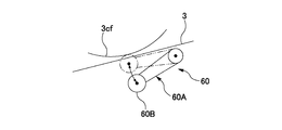
- the contact member is not limited to this, and may be, for example, a press roll 60B. That is, as shown in FIG. 12, the press mechanism 60 has a swing arm 60A and a rotatable press roll 60B provided at the swing end of the swing arm, and the press roll 60B is the material 3 ( It may be in contact with the preceding material 3a).
- the contact area when the press roll 60B hits the material 3 is small, and the material 3 is easily recessed. Then, when the material 3 is recessed, the conveyance path of the material 3 is changed by the amount of the recessed material 3 (the path length also changes), and the tension variation of the material 3 due to the route change occurs.
- the press roll 60B hits the material 3 as compared with the case of the press roll 60B (as shown by the contact portion 3b in FIG. 3). )
- the contact area becomes large, the dent of the material 3 becomes smaller. Therefore, it is possible to more appropriately suppress the tension fluctuation of the material 3.
- the above embodiment is preferable.
- the belt member 26F is rotated by the rotation of the first rotation roller 26B and the second rotation roller 26E while being stretched over the first rotation roller 26B and the second rotation roller 26E.
- the center axis of the first rotating roller 26B that is, the first fixed shaft 26A
- the contact is not limited to such a swing operation, and as shown in FIG. 13, the belt member 26F moves straight from the standby position to the contact position (contacts) as shown in FIG. Also good.
- the belt member 26F When the belt member 26F is moved from the standby position to the contact position by the swinging operation as described above (and returned from the contact position to the standby position), the belt member 26F is moved (returned) as shown in FIG. ) Compared to the case, the path of the material 3 during the movement (return) changes more slowly (the rate of change of the path length is smaller). In other words, the path is gradually changed in the case of the swing operation than in the case of the straight movement operation (because the path does not change at a stroke), so that a rapid fluctuation in the tension of the material 3 can be avoided. it can. As described above, the above-described embodiment is preferable in that it is possible to more appropriately suppress the tension fluctuation of the material 3.
Abstract
Description
搬送される前記資材を先行資材として該先行資材に後行資材の先端部を接合して前記先行資材に前記後行資材を繋ぐことと、
前記先行資材と前記後行資材の接合部よりも前記搬送方向において上流側の位置において前記先行資材をカットし、前記先行資材のヒレ部を前記接合部よりも上流側に形成することと、
前記接合部と、前記ヒレ部と前記後行資材が重なった重なり部とが前記搬送方向に沿って並ぶように設けられた資材の搬送を、該資材が前記入口ロール及び前記移動ロールに掛け渡された状態で継続することと、
前記移動ロールが基準位置に位置するように前記資材の搬送を制御することと、を有する資材継ぎ方法であって、
前記ヒレ部を形成する際には、
前記入口ロールに掛け渡された前記資材の掛渡し部の下流端から前記基準位置に位置するときの前記移動ロールに掛け渡された前記資材の掛渡し部の上流端までの前記資材の経路長よりも、前記接合部及び前記重なり部の合計長さが長くなるように、前記先行資材をカットすることを特徴とする資材継ぎ方法である。 The main invention for achieving the above object is to convey the material in the conveying direction in a state where the material related to the absorbent article is stretched over the entrance roll and the moving roll of the dancer unit,
Connecting the following material to the preceding material by joining the leading material of the following material to the preceding material as the preceding material to be conveyed;
Cutting the preceding material at a position upstream of the joining portion of the preceding material and the succeeding material in the conveying direction, and forming a fin portion of the preceding material upstream of the joining portion;
The material is transferred between the inlet roll and the moving roll, and the material is provided such that the joining portion, the fin portion, and the overlapping portion where the succeeding material overlaps are arranged along the conveying direction. To continue in the
Controlling the conveyance of the material so that the moving roll is located at a reference position,
When forming the fin portion,
The path length of the material from the downstream end of the material transfer portion passed over the inlet roll to the upstream end of the material transfer portion over the moving roll when positioned at the reference position The material splicing method is characterized in that the preceding material is cut so that the total length of the joining portion and the overlapping portion becomes longer.
搬送される前記資材を先行資材として該先行資材に後行資材の先端部を接合して前記先行資材に前記後行資材を繋ぐことと、
前記先行資材と前記後行資材の接合部よりも前記搬送方向において上流側の位置において前記先行資材をカットし、前記先行資材のヒレ部を前記接合部よりも上流側に形成することと、
前記接合部と、前記ヒレ部と前記後行資材が重なった重なり部とが前記搬送方向に沿って並ぶように設けられた資材の搬送を、該資材が前記入口ロール及び前記移動ロールに掛け渡された状態で継続することと、
前記移動ロールが基準位置に位置するように前記資材の搬送を制御することと、を有する資材継ぎ方法であって、
前記ヒレ部を形成する際には、
前記入口ロールに掛け渡された前記資材の掛渡し部の下流端から前記基準位置に位置するときの前記移動ロールに掛け渡された前記資材の掛渡し部の上流端までの前記資材の経路長よりも、前記接合部及び前記重なり部の合計長さが長くなるように、前記先行資材をカットすることを特徴とする資材継ぎ方法。 Conveying the material in the conveying direction in a state where the material related to the absorbent article is stretched over the entrance roll and the moving roll of the dancer unit;
Connecting the following material to the preceding material by joining the leading material of the following material to the preceding material as the preceding material to be conveyed;
Cutting the preceding material at a position upstream of the joining portion of the preceding material and the succeeding material in the conveying direction, and forming a fin portion of the preceding material upstream of the joining portion;
The material is transferred between the inlet roll and the moving roll, and the material is provided such that the joining portion, the fin portion, and the overlapping portion where the succeeding material overlaps are arranged along the conveying direction. To continue in the
Controlling the conveyance of the material so that the moving roll is located at a reference position,
When forming the fin portion,
The path length of the material from the downstream end of the material transfer portion passed over the inlet roll to the upstream end of the material transfer portion over the moving roll when positioned at the reference position The material splicing method is characterized in that the preceding material is cut so that the total length of the joining portion and the overlapping portion becomes longer.
前記ヒレ部を形成する際には、
前記入口ロールに掛け渡された前記資材の掛渡し部の下流端から前記基準位置に位置するときの前記移動ロールに掛け渡された前記資材の掛渡し部の下流端までの前記資材の経路長よりも、前記重なり部の長さが長くなるように、前記先行資材をカットすることが望ましい。 Such a material splicing method,
When forming the fin portion,
The path length of the material from the downstream end of the material transfer portion passed over the inlet roll to the downstream end of the material transfer portion over the moving roll when located at the reference position It is preferable to cut the preceding material so that the length of the overlapping portion becomes longer.
前記資材が前記ダンサーユニットの前記入口ロール、前記移動ロール、及び、出口ロールに掛け渡された状態で前記資材を搬送方向に搬送し、
前記先行資材に前記後行資材を繋いだ後には、前記接合部と前記重なり部とが前記搬送方向に沿って並ぶように設けられた資材の搬送を、該資材が前記入口ロール、前記移動ロール、及び、前記出口ロールに掛け渡された状態で継続し、
前記ヒレ部を形成する際には、
前記入口ロールに掛け渡された前記資材の掛渡し部の下流端から前記基準位置に位置するときの前記移動ロールを経由して前記出口ロールに掛け渡された前記資材の掛渡し部の上流端までの前記資材の経路長よりも、前記接合部及び前記重なり部の合計長さが長くなるように、前記先行資材をカットすることが望ましい。 Such a material splicing method,
The material is transported in the transport direction in a state where the material is stretched over the entrance roll, the moving roll, and the exit roll of the dancer unit,
After connecting the succeeding material to the preceding material, the material is provided to transport the material provided so that the joining portion and the overlapping portion are aligned along the transport direction, and the material is the entrance roll, the moving roll. , And continue in the state of being stretched over the exit roll,
When forming the fin portion,
The upstream end of the material passing portion that is passed to the outlet roll via the moving roll when located at the reference position from the downstream end of the material passing portion that is passed to the inlet roll It is desirable to cut the preceding material so that the total length of the joint portion and the overlapping portion is longer than the path length of the material.
前記ヒレ部を形成する際には、
前記入口ロールに掛け渡された前記資材の掛渡し部の下流端から前記基準位置に位置するときの前記移動ロールを経由して前記出口ロールに掛け渡された前記資材の掛渡し部の下流端までの前記資材の経路長よりも、前記重なり部の長さが長くなるように、前記先行資材をカットすることが望ましい。 Such a material splicing method,
When forming the fin portion,
The downstream end of the material passing portion that is passed to the outlet roll via the moving roll when located at the reference position from the downstream end of the material passing portion that is passed to the inlet roll It is desirable to cut the preceding material so that the length of the overlapping portion is longer than the path length of the material up to.
前記資材が前記ダンサーユニットの前記入口ロール、前記移動ロール、及び、出口ロールに掛け渡された状態で前記資材を搬送方向に搬送し、
前記先行資材に前記後行資材を繋いだ後には、前記接合部と前記重なり部とが前記搬送方向に沿って並ぶように設けられた資材の搬送を、該資材が前記入口ロール、前記移動ロール、及び、前記出口ロールに掛け渡された状態で継続し、
前記ヒレ部を形成する際には、
前記入口ロールに掛け渡された前記資材の掛渡し部の下流端から前記基準位置に位置するときの前記移動ロールを経由して前記出口ロールに掛け渡された前記資材の掛渡し部の上流端までの前記資材の経路長よりも、前記接合部及び前記重なり部の合計長さが短くなるように、前記先行資材をカットすることが望ましい。 Such a material splicing method,
The material is transported in the transport direction in a state where the material is stretched over the entrance roll, the moving roll, and the exit roll of the dancer unit,
After connecting the succeeding material to the preceding material, the material is provided to transport the material provided so that the joining portion and the overlapping portion are aligned along the transport direction, and the material is the entrance roll, the moving roll. , And continue in the state of being stretched over the exit roll,
When forming the fin portion,
The upstream end of the material passing portion that is passed to the outlet roll via the moving roll when located at the reference position from the downstream end of the material passing portion that is passed to the inlet roll It is desirable to cut the preceding material so that the total length of the joining portion and the overlapping portion is shorter than the path length of the material.
前記ヒレ部を形成する際には、
前記入口ロールに掛け渡された前記資材の掛渡し部の上流端から前記基準位置に位置するときの前記移動ロールに掛け渡された前記資材の掛渡し部の上流端までの前記資材の経路長よりも、前記接合部及び前記重なり部の合計長さが長くなるように、前記先行資材をカットすることが望ましい。 Such a material splicing method,
When forming the fin portion,
The path length of the material from the upstream end of the material transfer portion passed over the inlet roll to the upstream end of the material transfer portion over the moving roll when located at the reference position It is preferable to cut the preceding material so that the total length of the joint and the overlapping portion becomes longer.
搬送される前記先行資材に前記後行資材を接合する際には、待機位置から前記先行資材に当接する当接位置へ当接部材を移動させて前記先行資材を前記後行資材に押し付け、
搬送される前記資材の前記接合部が前記移動ロールに差し掛かった後に、前記当接部材を前記当接位置から前記待機位置へ戻し、
前記ヒレ部を形成する際には、
前記当接部材に当接する前記資材の当接部の下流端から前記基準位置に位置するときの前記移動ロールに掛け渡された前記資材の掛渡し部の上流端までの前記資材の経路長よりも、前記接合部及び前記重なり部の合計長さが長くなるように、前記先行資材をカットすることが望ましい。 Such a material splicing method,
When joining the succeeding material to the preceding material to be transported, the contact member is moved from a standby position to a contact position contacting the preceding material, and the preceding material is pressed against the succeeding material,
After the joint portion of the material to be conveyed has reached the moving roll, the contact member is returned from the contact position to the standby position,
When forming the fin portion,
From the path length of the material from the downstream end of the contact portion of the material that contacts the contact member to the upstream end of the transfer portion of the material that is stretched over the moving roll when positioned at the reference position However, it is desirable to cut the preceding material so that the total length of the joint and the overlapped portion becomes longer.
搬送される前記資材の前記接合部が前記移動ロールを通り過ぎた後に、前記当接部材を前記当接位置から前記待機位置へ戻し、
前記ヒレ部を形成する際には、
前記当接部材に当接する前記資材の当接部の下流端から前記基準位置に位置するときの前記移動ロールに掛け渡された前記資材の掛渡し部の下流端までの前記資材の経路長よりも、前記重なり部の長さが長くなるように、前記先行資材をカットすることが望ましい。 Such a material splicing method,
After the joint portion of the material to be conveyed has passed the moving roll, the contact member is returned from the contact position to the standby position,
When forming the fin portion,
From the path length of the material from the downstream end of the contact portion of the material that contacts the contact member to the downstream end of the transfer portion of the material that is stretched over the moving roll when positioned at the reference position However, it is desirable to cut the preceding material so that the length of the overlapping portion becomes longer.
搬送される前記先行資材に前記後行資材を接合する際には、待機位置から前記先行資材に当接する当接位置へ当接部材を移動させて前記先行資材を前記後行資材に押し付け、
前記ヒレ部を形成する際には、
前記当接部材に当接する前記資材の当接部の下流端から前記基準位置に位置するときの前記移動ロールに掛け渡された前記資材の掛渡し部の上流端までの前記資材の経路長よりも、前記接合部及び前記重なり部の合計長さが短くなるように、前記先行資材をカットすることが望ましい。 Such a material splicing method,
When joining the succeeding material to the preceding material to be transported, the contact member is moved from a standby position to a contact position contacting the preceding material, and the preceding material is pressed against the succeeding material,
When forming the fin portion,
From the path length of the material from the downstream end of the contact portion of the material that contacts the contact member to the upstream end of the transfer portion of the material that is stretched over the moving roll when positioned at the reference position However, it is desirable to cut the preceding material so that the total length of the joining portion and the overlapping portion is shortened.
搬送される前記先行資材に前記後行資材を接合する際には、待機位置から前記先行資材に当接する当接位置へ当接部材を移動させて前記先行資材を前記後行資材に押し付け、
前記当接部材が前記当接位置へ位置している状態で、前記先行資材をカットすることが望ましい。 Such a material splicing method,
When joining the succeeding material to the preceding material to be transported, the contact member is moved from a standby position to a contact position contacting the preceding material, and the preceding material is pressed against the succeeding material,
It is desirable to cut the preceding material in a state where the contact member is located at the contact position.
搬送される前記資材の前記ヒレ部が前記当接部材と当接しなくなってから、前記当接部材を前記当接位置から前記待機位置へ戻すことが望ましい。 Such a material splicing method,
It is desirable that the contact member is returned from the contact position to the standby position after the fin portion of the material to be conveyed does not contact the contact member.
搬送される前記先行資材に前記後行資材を接合する際には、待機位置から前記先行資材に当接する当接位置へ当接部材を移動させて前記先行資材を前記後行資材に押し付け、
前記当接部材は、回転可能なベルト部材であることが望ましい。 Such a material splicing method,
When joining the succeeding material to the preceding material to be transported, the contact member is moved from a standby position to a contact position contacting the preceding material, and the preceding material is pressed against the succeeding material,
The contact member is preferably a rotatable belt member.
前記ベルト部材は、第一回転ローラー及び第二回転ローラーに掛け渡された状態で該第一回転ローラー及び該第二回転ローラーが回転することにより回転し、かつ、前記第一回転ローラーの中心軸を揺動軸として揺動することにより前記待機位置から前記当接位置へ移動する部材であることが望ましい。 Such a material splicing method,
The belt member rotates when the first rotation roller and the second rotation roller rotate in a state of being stretched between the first rotation roller and the second rotation roller, and the central axis of the first rotation roller It is desirable that the member moves from the standby position to the contact position by swinging around the swing axis.
前記資材は、一方面の繊維密度が他方面よりも高い繊維集合体の連続シートであり、
搬送される前記先行資材に前記後行資材を接合する際には、待機位置から前記先行資材の前記一方面に当接する当接位置へ当接部材を移動させて、前記先行資材と前記後行資材との間に接着部材が挟まれた状態で該先行資材を該後行資材に押し付けることが望ましい。 Such a material splicing method,
The material is a continuous sheet of a fiber assembly in which the fiber density on one side is higher than that on the other side,
When joining the succeeding material to the preceding material to be transported, a contact member is moved from a standby position to a contact position contacting the one surface of the preceding material, and the preceding material and the following material are moved. It is desirable to press the preceding material against the succeeding material in a state where an adhesive member is sandwiched between the material and the material.
前記資材は、一方面の繊維密度が他方面よりも高い繊維集合体の連続シートであり、
前記先行資材をカットして前記ヒレ部を形成する際には、カッター刃を前記一方面側から入れることが望ましい。 Such a material splicing method,
The material is a continuous sheet of a fiber assembly in which the fiber density on one side is higher than that on the other side,
When forming the fin portion by cutting the preceding material, it is desirable to insert a cutter blade from the one surface side.
吸収性物品に係る資材が前記入口ロール及び移動ロールに掛け渡された状態で前記資材を搬送方向に搬送する搬送部と、
搬送される前記資材を先行資材として該先行資材に後行資材の先端部を接合して前記先行資材に前記後行資材を繋ぐ資材継ぎ部と、
前記先行資材と前記後行資材の接合部よりも前記搬送方向において上流側の位置において前記先行資材をカットし、前記先行資材のヒレ部を前記接合部よりも上流側に形成するカット部と、を有し、
前記搬送部は、前記接合部と、前記ヒレ部と前記後行資材が重なった重なり部とが前記搬送方向に沿って並ぶように設けられた資材の搬送を、該資材が前記入口ロール及び前記移動ロールに掛け渡された状態で継続し、
前記移動ロールが基準位置に位置するように前記資材の搬送を制御する制御部を備え、
前記カット部は、前記入口ロールに掛け渡された前記資材の掛渡し部の下流端から前記基準位置に位置するときの前記移動ロールに掛け渡された前記資材の掛渡し部の上流端までの前記資材の経路長よりも、前記接合部及び前記重なり部の合計長さが長くなるように、前記先行資材をカットすることを特徴とする資材供給装置。 Next, a dancer unit having an entrance roll and a moving roll;
A transport unit that transports the material in the transport direction in a state where the material related to the absorbent article is stretched over the inlet roll and the moving roll;
A material joint that joins the preceding material to the preceding material by joining the leading material of the following material as the preceding material to be conveyed, and the preceding material;
Cutting the preceding material at a position upstream of the joining portion of the preceding material and the succeeding material in the transport direction, and forming a fin portion of the preceding material upstream of the joining portion; and Have
The conveyance unit is configured to convey the material provided such that the joining portion, the fin portion, and the overlapping portion where the succeeding material overlaps are arranged along the conveyance direction, and the material includes the inlet roll and the Continue on the moving roll,
A control unit that controls conveyance of the material so that the moving roll is located at a reference position;
The cut portion extends from the downstream end of the material transfer portion extended over the inlet roll to the upstream end of the material transfer portion extended over the moving roll when positioned at the reference position. The material supply device is characterized in that the preceding material is cut so that a total length of the joining portion and the overlapping portion is longer than a route length of the material.
図1Aは、吸収性物品の製造ラインLMの概略側面図であり、図1Bは、図1A中のB-B矢視で示す同ラインLMの概略平面図である。なお、図1A及び図1Bでは、図の錯綜を防ぐ目的で、本来見えるべきものを省略している場合がある。
この製造ラインLMでは、吸収性物品の一例として使い捨ておむつ1を製造する。また、同ラインLMでは、資材3として、複数の繊維集合体の連続シート3,3…が使用される。例えば、不織布やティッシュ等の柔軟で可撓性のある連続シート3が複数使用される。そして、同資材3,3…の製造ラインLMへの搬入は、資材たる連続シート3をコイル状に紙管3p(図2A)に巻き取ってなる資材コイル3Cの形態でなされる。なお、連続シート3については、そのおもて面(一方面に相当)の繊維密度の方が裏面(他方面に相当)の繊維密度よりも高くなっている。そして、当該おもて面が資材コイル3Cの外周面となり当該裏面が資材コイル3Cの内周面となるように連続シート3が資材コイル3Cに巻かれている。 === This Embodiment ===
FIG. 1A is a schematic side view of an absorbent article production line LM, and FIG. 1B is a schematic plan view of the line LM indicated by arrows BB in FIG. 1A. In addition, in FIG. 1A and FIG. 1B, the thing which should be visible may be abbreviate | omitted for the purpose of preventing the complication of a figure.
In this production line LM, a disposable diaper 1 is produced as an example of an absorbent article. Further, in the same line LM, as the
積繊装置110aは、例えばパルプ繊維などの液体吸収性繊維を主材として、上記部材としての吸収体2を生成する。
カット装置110bは、資材3を単票状に切断して防漏シート3sを生成するとともに、搬送方向に隣り合う防漏シート3s,3s同士の間に間隔をあけた状態にして搬送する。そして、この間隔をあけた状態のまま各防漏シート3sを、別の資材3に接合する。なお、このカット装置110bの一例としては、周知のスリップカット装置(例えば特開2011-083547)を例示できる。
プレス装置110cは、上下一対のロールによって資材3,3…同士を押圧する。
レッグホールカット装置110dは、上下一対のロールによって、資材3,3…に脚回り開口部を形成する。
エンドカット装置110eは、上下一対ロールによって、資材3,3…から使い捨ておむつ1を切り離して同使い捨ておむつ1を生成する。 Examples of the
The
The
The
The leg
The end cut
資材継ぎ装置20は、製造ラインLMの床部LMBに立設する所謂鏡板等の支持板21と、X方向に沿った旋回軸C22回りに旋回可能に上記支持板21に支持された帯板状のターレット22と、ターレット22の長手方向の両端部に設けられX方向に沿った二つの繰り出し用回転軸24,24(搬送部に相当)と、ターレット22を駆動回転する不図示のサーボモーターと、二つの繰り出し用回転軸24,24をそれぞれ独立に駆動回転する不図示の各サーボモーターと、一方の繰り出し用回転軸24で繰り出し中の先行資材3aを、他方の繰り出し用回転軸24で支持された後行資材コイル3Cfの外周面3Cfs(すなわち、おもて面)に押し付けて後行資材3fに接合するプレス機構26(資材継ぎ部に相当)と、接合後先行資材3aを先行資材コイル3Caの紙管3pから切り離すカッター機構28(カット部に相当)と、これらを制御するコンピュータやシーケンサ等の不図示のコントローラと、を有する。 Hereinafter, each structure which concerns on the
The
次に、資材継ぎが行われるときの製造ラインLM(資材供給装置10)の動作について、図2A、図3、及び、図4を参照しつつ説明する。図3は、先行資材3aをカットする際の資材3の様子を模式的に表した図である。図4は、ベルト部材26Fが待機位置へ戻る際の資材3の様子を模式的に表した図である。 <<< Operation related to material splicing >>>
Next, the operation of the production line LM (material supply apparatus 10) when material splicing is performed will be described with reference to FIGS. 2A, 3 and 4. FIG. FIG. 3 is a diagram schematically showing the state of the
前述したとおり、本実施の形態においては、先行資材3aと後行資材3fを接合し、先行資材3aのカット処理を行う際に、接合部3jに引き続いてヒレ部3atが形成されるように先行資材3aをカットする。そして、ヒレ部3atの長さが所定長さとなるようにカットを行う。 === About the length of the fin portion 3at ===
As described above, in the present embodiment, when the preceding
上記の実施形態は、本発明の理解を容易にするためのものであり、本発明を限定して解釈するためのものではない。本発明は、その趣旨を逸脱することなく、変更・改良され得ると共に、本発明には、その等価物が含まれることは言うまでもない。 === Other Embodiments ===
The above-described embodiments are for facilitating the understanding of the present invention, and are not intended to limit the present invention. The present invention can be modified and improved without departing from the gist thereof, and it goes without saying that the present invention includes equivalents thereof.
3 連続シート(資材)、
3C 資材コイル、3Ca 先行資材コイル、3Cf 後行資材コイル、
3Cfs 外周面、3Cn 資材コイル、3Cns 外周面、
3L ループ、
3a 先行資材、3at ヒレ部、3b 当接部、3d 重なり部、3f 後行資材、3fe 先端部、3j 接合部、3n 資材、3ne 先端部、
3p 紙管、3s 防漏シート、3t 掛渡し部
4j 両面テープ(接着部材)、4k 両面テープ、
10 資材供給装置、20 資材継ぎ装置、21 支持板、22 ターレット、
24 繰り出し用回転軸(回転軸)、
26 プレス機構、26A 第一固定軸(中心軸)、26B 第一回転ローラー、26C 揺動アーム、26D 第二固定軸、26E 第二回転ローラー、26F ベルト部材(当接部材)、26G アクチュエータ、
28 カッター機構、28A アーム部材、28B カッター刃、
28C アクチュエータ、
29R 搬送ロール、
40 蓄積装置(ダンサーユニット)、41A アーム部材、41C アクチュエータ、
41d 出口ロール、41m 移動ロール、41u 入口ロール、
50 ターンバー(搬送方向変更部材)、
60 プレス機構、60A 揺動アーム 60B プレスロール(当接部材)、
110 加工ユニット(加工装置)、110a 積繊機、110b カット装置、
110c プレス装置、110d レッグホールカット装置、
110e エンドカット装置、
LM 製造ライン、LMB 床部、
P3Ca 先行資材コイル位置、P3Cf 後行資材コイル位置、
C22 旋回軸、C28A 回転軸、
C41A 回転軸、C41u 回転軸、C41m 回転軸、C41d 回転軸、 1 disposable diaper (absorbent article), 2 absorber,
3 Continuous sheet (material),
3C material coil, 3Ca preceding material coil, 3Cf following material coil,
3Cfs outer peripheral surface, 3Cn material coil, 3Cns outer peripheral surface,
3L loop,
3a Lead material, 3at fin part, 3b contact part, 3d overlap part, 3f trailing material, 3fe tip part, 3j joint part, 3n material, 3ne tip part,
3p paper tube, 3s leak-proof sheet, 3t hanging part 4j double-sided tape (adhesive member), 4k double-sided tape,
10 Material supply device, 20 Material splicing device, 21 Support plate, 22 Turret,
24 Rotating shaft for rotation (Rotating shaft),
26 press mechanism, 26A first fixed shaft (center shaft), 26B first rotating roller, 26C swing arm, 26D second fixed shaft, 26E second rotating roller, 26F belt member (contact member), 26G actuator,
28 cutter mechanism, 28A arm member, 28B cutter blade,
28C actuator,
29R transport roll,
40 storage device (dancer unit), 41A arm member, 41C actuator,
41d outlet roll, 41m moving roll, 41u inlet roll,
50 turn bar (conveyance direction changing member),
60 Press mechanism,
110 processing unit (processing device), 110a fiber stacker, 110b cutting device,
110c press device, 110d leg hole cut device,
110e end cut device,
LM production line, LMB floor,
P3Ca preceding material coil position, P3Cf following material coil position,
C22 rotation axis, C28A rotation axis,
C41A rotation axis, C41u rotation axis, C41m rotation axis, C41d rotation axis,
Claims (16)
- 吸収性物品に係る資材がダンサーユニットの入口ロール及び移動ロールに掛け渡された状態で前記資材を搬送方向に搬送することと、
搬送される前記資材を先行資材として該先行資材に後行資材の先端部を接合して前記先行資材に前記後行資材を繋ぐことと、
前記先行資材と前記後行資材の接合部よりも前記搬送方向において上流側の位置において前記先行資材をカットし、前記先行資材のヒレ部を前記接合部よりも上流側に形成することと、
前記接合部と、前記ヒレ部と前記後行資材が重なった重なり部とが前記搬送方向に沿って並ぶように設けられた資材の搬送を、該資材が前記入口ロール及び前記移動ロールに掛け渡された状態で継続することと、
前記移動ロールが基準位置に位置するように前記資材の搬送を制御することと、を有する資材継ぎ方法であって、
前記ヒレ部を形成する際には、
前記入口ロールに掛け渡された前記資材の掛渡し部の下流端から前記基準位置に位置するときの前記移動ロールに掛け渡された前記資材の掛渡し部の上流端までの前記資材の経路長よりも、前記接合部及び前記重なり部の合計長さが長くなるように、前記先行資材をカットすることを特徴とする資材継ぎ方法。 Conveying the material in the conveying direction in a state where the material related to the absorbent article is stretched over the entrance roll and the moving roll of the dancer unit;
Connecting the following material to the preceding material by joining the leading material of the following material to the preceding material as the preceding material to be conveyed;
Cutting the preceding material at a position upstream of the joining portion of the preceding material and the succeeding material in the conveying direction, and forming a fin portion of the preceding material upstream of the joining portion;
The material is transferred between the inlet roll and the moving roll, and the material is provided such that the joining portion, the fin portion, and the overlapping portion where the succeeding material overlaps are arranged along the conveying direction. To continue in the
Controlling the conveyance of the material so that the moving roll is located at a reference position,
When forming the fin portion,
The path length of the material from the downstream end of the material transfer portion passed over the inlet roll to the upstream end of the material transfer portion over the moving roll when positioned at the reference position The material splicing method is characterized in that the preceding material is cut so that the total length of the joining portion and the overlapping portion becomes longer. - 請求項1に記載の資材継ぎ方法であって、
前記ヒレ部を形成する際には、
前記入口ロールに掛け渡された前記資材の掛渡し部の下流端から前記基準位置に位置するときの前記移動ロールに掛け渡された前記資材の掛渡し部の下流端までの前記資材の経路長よりも、前記重なり部の長さが長くなるように、前記先行資材をカットすることを特徴とする資材継ぎ方法。 The material splicing method according to claim 1,
When forming the fin portion,
The path length of the material from the downstream end of the material transfer portion passed over the inlet roll to the downstream end of the material transfer portion over the moving roll when located at the reference position The material splicing method is characterized in that the preceding material is cut so that the length of the overlapping portion becomes longer. - 請求項2に記載の資材継ぎ方法であって、
前記資材が前記ダンサーユニットの前記入口ロール、前記移動ロール、及び、出口ロールに掛け渡された状態で前記資材を搬送方向に搬送し、
前記先行資材に前記後行資材を繋いだ後には、前記接合部と前記重なり部とが前記搬送方向に沿って並ぶように設けられた資材の搬送を、該資材が前記入口ロール、前記移動ロール、及び、前記出口ロールに掛け渡された状態で継続し、
前記ヒレ部を形成する際には、
前記入口ロールに掛け渡された前記資材の掛渡し部の下流端から前記基準位置に位置するときの前記移動ロールを経由して前記出口ロールに掛け渡された前記資材の掛渡し部の上流端までの前記資材の経路長よりも、前記接合部及び前記重なり部の合計長さが長くなるように、前記先行資材をカットすることを特徴とする資材継ぎ方法。 The material splicing method according to claim 2,
The material is transported in the transport direction in a state where the material is stretched over the entrance roll, the moving roll, and the exit roll of the dancer unit,
After connecting the succeeding material to the preceding material, the material is provided to transport the material provided so that the joining portion and the overlapping portion are aligned along the transport direction, and the material is the entrance roll, the moving roll. , And continue in the state of being stretched over the exit roll,
When forming the fin portion,
The upstream end of the material passing portion that is passed to the outlet roll via the moving roll when located at the reference position from the downstream end of the material passing portion that is passed to the inlet roll The material splicing method is characterized in that the preceding material is cut so that a total length of the joining portion and the overlapping portion is longer than a path length of the material up to. - 請求項3に記載の資材継ぎ方法であって、
前記ヒレ部を形成する際には、
前記入口ロールに掛け渡された前記資材の掛渡し部の下流端から前記基準位置に位置するときの前記移動ロールを経由して前記出口ロールに掛け渡された前記資材の掛渡し部の下流端までの前記資材の経路長よりも、前記重なり部の長さが長くなるように、前記先行資材をカットすることを特徴とする資材継ぎ方法。 The material splicing method according to claim 3,
When forming the fin portion,
The downstream end of the material passing portion that is passed to the outlet roll via the moving roll when located at the reference position from the downstream end of the material passing portion that is passed to the inlet roll The material splicing method is characterized in that the preceding material is cut so that the length of the overlapping portion is longer than the path length of the material up to. - 請求項2に記載の資材継ぎ方法であって、
前記資材が前記ダンサーユニットの前記入口ロール、前記移動ロール、及び、出口ロールに掛け渡された状態で前記資材を搬送方向に搬送し、
前記先行資材に前記後行資材を繋いだ後には、前記接合部と前記重なり部とが前記搬送方向に沿って並ぶように設けられた資材の搬送を、該資材が前記入口ロール、前記移動ロール、及び、前記出口ロールに掛け渡された状態で継続し、
前記ヒレ部を形成する際には、
前記入口ロールに掛け渡された前記資材の掛渡し部の下流端から前記基準位置に位置するときの前記移動ロールを経由して前記出口ロールに掛け渡された前記資材の掛渡し部の上流端までの前記資材の経路長よりも、前記接合部及び前記重なり部の合計長さが短くなるように、前記先行資材をカットすることを特徴とする資材継ぎ方法。 The material splicing method according to claim 2,
The material is transported in the transport direction in a state where the material is stretched over the entrance roll, the moving roll, and the exit roll of the dancer unit,
After connecting the succeeding material to the preceding material, the material is provided to transport the material provided so that the joining portion and the overlapping portion are aligned along the transport direction, and the material is the entrance roll, the moving roll. , And continue in the state of being stretched over the exit roll,
When forming the fin portion,
The upstream end of the material passing portion that is passed to the outlet roll via the moving roll when located at the reference position from the downstream end of the material passing portion that is passed to the inlet roll The material splicing method is characterized in that the preceding material is cut so that a total length of the joining portion and the overlapping portion is shorter than a path length of the material up to. - 請求項1乃至請求項5に記載の資材継ぎ方法であって、
前記ヒレ部を形成する際には、
前記入口ロールに掛け渡された前記資材の掛渡し部の上流端から前記基準位置に位置するときの前記移動ロールに掛け渡された前記資材の掛渡し部の上流端までの前記資材の経路長よりも、前記接合部及び前記重なり部の合計長さが長くなるように、前記先行資材をカットすることを特徴とする資材継ぎ方法。 The material splicing method according to any one of claims 1 to 5,
When forming the fin portion,
The path length of the material from the upstream end of the material transfer portion passed over the inlet roll to the upstream end of the material transfer portion over the moving roll when located at the reference position The material splicing method is characterized in that the preceding material is cut so that the total length of the joining portion and the overlapping portion becomes longer. - 請求項6に記載の資材継ぎ方法であって、
搬送される前記先行資材に前記後行資材を接合する際には、待機位置から前記先行資材に当接する当接位置へ当接部材を移動させて前記先行資材を前記後行資材に押し付け、
搬送される前記資材の前記接合部が前記移動ロールに差し掛かった後に、前記当接部材を前記当接位置から前記待機位置へ戻し、
前記ヒレ部を形成する際には、
前記当接部材に当接する前記資材の当接部の下流端から前記基準位置に位置するときの前記移動ロールに掛け渡された前記資材の掛渡し部の上流端までの前記資材の経路長よりも、前記接合部及び前記重なり部の合計長さが長くなるように、前記先行資材をカットすることを特徴とする資材継ぎ方法。 The material splicing method according to claim 6,
When joining the succeeding material to the preceding material to be transported, the contact member is moved from a standby position to a contact position contacting the preceding material, and the preceding material is pressed against the succeeding material,
After the joint portion of the material to be conveyed has reached the moving roll, the contact member is returned from the contact position to the standby position,
When forming the fin portion,
From the path length of the material from the downstream end of the contact portion of the material that contacts the contact member to the upstream end of the transfer portion of the material that is stretched over the moving roll when positioned at the reference position The material splicing method is characterized in that the preceding material is cut so that a total length of the joining portion and the overlapping portion is increased. - 請求項7に記載の資材継ぎ方法であって、
搬送される前記資材の前記接合部が前記移動ロールを通り過ぎた後に、前記当接部材を前記当接位置から前記待機位置へ戻し、
前記ヒレ部を形成する際には、
前記当接部材に当接する前記資材の当接部の下流端から前記基準位置に位置するときの前記移動ロールに掛け渡された前記資材の掛渡し部の下流端までの前記資材の経路長よりも、前記重なり部の長さが長くなるように、前記先行資材をカットすることを特徴とする資材継ぎ方法。 The material splicing method according to claim 7,
After the joint portion of the material to be conveyed has passed the moving roll, the contact member is returned from the contact position to the standby position,
When forming the fin portion,
From the path length of the material from the downstream end of the contact portion of the material that contacts the contact member to the downstream end of the transfer portion of the material that is stretched over the moving roll when positioned at the reference position The material splicing method is characterized in that the preceding material is cut so that the length of the overlapping portion becomes longer. - 請求項6に記載の資材継ぎ方法であって、
搬送される前記先行資材に前記後行資材を接合する際には、待機位置から前記先行資材に当接する当接位置へ当接部材を移動させて前記先行資材を前記後行資材に押し付け、
前記ヒレ部を形成する際には、
前記当接部材に当接する前記資材の当接部の下流端から前記基準位置に位置するときの前記移動ロールに掛け渡された前記資材の掛渡し部の上流端までの前記資材の経路長よりも、前記接合部及び前記重なり部の合計長さが短くなるように、前記先行資材をカットすることを特徴とする資材継ぎ方法。 The material splicing method according to claim 6,
When joining the succeeding material to the preceding material to be transported, the contact member is moved from a standby position to a contact position contacting the preceding material, and the preceding material is pressed against the succeeding material,
When forming the fin portion,
From the path length of the material from the downstream end of the contact portion of the material that contacts the contact member to the upstream end of the transfer portion of the material that is stretched over the moving roll when positioned at the reference position The material splicing method is characterized in that the preceding material is cut so that a total length of the joining portion and the overlapping portion is shortened. - 請求項1乃至請求項9のいずれかに記載の資材継ぎ方法であって、
搬送される前記先行資材に前記後行資材を接合する際には、待機位置から前記先行資材に当接する当接位置へ当接部材を移動させて前記先行資材を前記後行資材に押し付け、
前記当接部材が前記当接位置へ位置している状態で、前記先行資材をカットすることを特徴とする資材継ぎ方法。 A material splicing method according to any one of claims 1 to 9,
When joining the succeeding material to the preceding material to be transported, the contact member is moved from a standby position to a contact position contacting the preceding material, and the preceding material is pressed against the succeeding material,
The material splicing method, wherein the preceding material is cut in a state where the contact member is located at the contact position. - 請求項10に記載の資材継ぎ方法であって、
搬送される前記資材の前記ヒレ部が前記当接部材と当接しなくなってから、前記当接部材を前記当接位置から前記待機位置へ戻すことを特徴とする資材継ぎ方法。 The material splicing method according to claim 10,
A material splicing method, wherein the contact member is returned from the contact position to the standby position after the fin portion of the material to be conveyed does not contact the contact member. - 請求項1乃至請求項11のいずれかに記載の資材継ぎ方法であって、
搬送される前記先行資材に前記後行資材を接合する際には、待機位置から前記先行資材に当接する当接位置へ当接部材を移動させて前記先行資材を前記後行資材に押し付け、
前記当接部材は、回転可能なベルト部材であることを特徴とする資材継ぎ方法。 A material splicing method according to any one of claims 1 to 11,
When joining the succeeding material to the preceding material to be transported, the contact member is moved from a standby position to a contact position contacting the preceding material, and the preceding material is pressed against the succeeding material,
The material splicing method, wherein the contact member is a rotatable belt member. - 請求項12に記載の資材継ぎ方法であって、
前記ベルト部材は、第一回転ローラー及び第二回転ローラーに掛け渡された状態で該第一回転ローラー及び該第二回転ローラーが回転することにより回転し、かつ、前記第一回転ローラーの中心軸を揺動軸として揺動することにより前記待機位置から前記当接位置へ移動する部材であることを特徴とする資材継ぎ方法。 The material splicing method according to claim 12,
The belt member rotates when the first rotation roller and the second rotation roller rotate in a state of being stretched between the first rotation roller and the second rotation roller, and the central axis of the first rotation roller A material splicing method characterized in that the material is a member that moves from the standby position to the contact position by swinging about a swing shaft. - 請求項1乃至請求項13のいずれかに記載の資材継ぎ方法であって、
前記資材は、一方面の繊維密度が他方面よりも高い繊維集合体の連続シートであり、
搬送される前記先行資材に前記後行資材を接合する際には、待機位置から前記先行資材の前記一方面に当接する当接位置へ当接部材を移動させて、前記先行資材と前記後行資材との間に接着部材が挟まれた状態で該先行資材を該後行資材に押し付けることを特徴とする資材継ぎ方法。 The material splicing method according to any one of claims 1 to 13,
The material is a continuous sheet of a fiber assembly in which the fiber density on one side is higher than that on the other side,
When joining the succeeding material to the preceding material to be transported, a contact member is moved from a standby position to a contact position contacting the one surface of the preceding material, and the preceding material and the following material are moved. A material splicing method comprising pressing the preceding material against the succeeding material in a state where an adhesive member is sandwiched between the material and the material. - 請求項1乃至請求項14のいずれかに記載の資材継ぎ方法であって、
前記資材は、一方面の繊維密度が他方面よりも高い繊維集合体の連続シートであり、
前記先行資材をカットして前記ヒレ部を形成する際には、カッター刃を前記一方面側から入れることを特徴とする資材継ぎ方法。 The material splicing method according to any one of claims 1 to 14,
The material is a continuous sheet of a fiber assembly in which the fiber density on one side is higher than that on the other side,
A material splicing method comprising inserting a cutter blade from the one surface side when the leading material is cut to form the fin portion. - 入口ロール及び移動ロールを有するダンサーユニットと、
吸収性物品に係る資材が前記入口ロール及び移動ロールに掛け渡された状態で前記資材を搬送方向に搬送する搬送部と、
搬送される前記資材を先行資材として該先行資材に後行資材の先端部を接合して前記先行資材に前記後行資材を繋ぐ資材継ぎ部と、
前記先行資材と前記後行資材の接合部よりも前記搬送方向において上流側の位置において前記先行資材をカットし、前記先行資材のヒレ部を前記接合部よりも上流側に形成するカット部と、を有し、
前記搬送部は、前記接合部と、前記ヒレ部と前記後行資材が重なった重なり部とが前記搬送方向に沿って並ぶように設けられた資材の搬送を、該資材が前記入口ロール及び前記移動ロールに掛け渡された状態で継続し、
前記移動ロールが基準位置に位置するように前記資材の搬送を制御する制御部を備え、
前記カット部は、前記入口ロールに掛け渡された前記資材の掛渡し部の下流端から前記基準位置に位置するときの前記移動ロールに掛け渡された前記資材の掛渡し部の上流端までの前記資材の経路長よりも、前記接合部及び前記重なり部の合計長さが長くなるように、前記先行資材をカットすることを特徴とする資材供給装置。 A dancer unit having an entrance roll and a moving roll;
A transport unit that transports the material in the transport direction in a state where the material related to the absorbent article is stretched over the inlet roll and the moving roll;
A material joint that joins the preceding material to the preceding material by joining the leading material of the following material as the preceding material to be conveyed, and the preceding material;
Cutting the preceding material at a position upstream of the joining portion of the preceding material and the succeeding material in the transport direction, and forming a fin portion of the preceding material upstream of the joining portion; and Have
The conveyance unit is configured to convey the material provided such that the joining portion, the fin portion, and the overlapping portion where the succeeding material overlaps are arranged along the conveyance direction, and the material includes the inlet roll and the Continue on the moving roll,
A control unit that controls conveyance of the material so that the moving roll is located at a reference position;
The cut portion extends from the downstream end of the material transfer portion extended over the inlet roll to the upstream end of the material transfer portion extended over the moving roll when positioned at the reference position. The material supply device is characterized in that the preceding material is cut so that a total length of the joining portion and the overlapping portion is longer than a route length of the material.
Priority Applications (6)
| Application Number | Priority Date | Filing Date | Title |
|---|---|---|---|
| US16/079,551 US20190038476A1 (en) | 2016-02-29 | 2016-02-29 | Method for splicing material and device for supplying material |
| RU2018134145A RU2687471C1 (en) | 2016-02-29 | 2016-02-29 | Method of matching material and material feeding device |
| JP2016557352A JP6051351B1 (en) | 2016-02-29 | 2016-02-29 | Material splicing method and material supply device |
| CN201680082749.2A CN108698778B (en) | 2016-02-29 | 2016-02-29 | Method for grafting material and the device for supplying material |
| PCT/JP2016/056099 WO2017149611A1 (en) | 2016-02-29 | 2016-02-29 | Material splicing method, and material supply device |
| EP16892456.1A EP3424853B1 (en) | 2016-02-29 | 2016-02-29 | Material splicing method, and material supply device |
Applications Claiming Priority (1)
| Application Number | Priority Date | Filing Date | Title |
|---|---|---|---|
| PCT/JP2016/056099 WO2017149611A1 (en) | 2016-02-29 | 2016-02-29 | Material splicing method, and material supply device |
Publications (1)
| Publication Number | Publication Date |
|---|---|
| WO2017149611A1 true WO2017149611A1 (en) | 2017-09-08 |
Family
ID=57582184
Family Applications (1)
| Application Number | Title | Priority Date | Filing Date |
|---|---|---|---|
| PCT/JP2016/056099 WO2017149611A1 (en) | 2016-02-29 | 2016-02-29 | Material splicing method, and material supply device |
Country Status (6)
| Country | Link |
|---|---|
| US (1) | US20190038476A1 (en) |
| EP (1) | EP3424853B1 (en) |
| JP (1) | JP6051351B1 (en) |
| CN (1) | CN108698778B (en) |
| RU (1) | RU2687471C1 (en) |
| WO (1) | WO2017149611A1 (en) |
Families Citing this family (1)
| Publication number | Priority date | Publication date | Assignee | Title |
|---|---|---|---|---|
| CN114368634B (en) * | 2021-12-17 | 2024-03-29 | 南京三英软件有限公司 | Separator roll changing connection method for storage battery separator conveying line |
Citations (6)
| Publication number | Priority date | Publication date | Assignee | Title |
|---|---|---|---|---|
| JPH05270706A (en) * | 1992-03-25 | 1993-10-19 | Isowa Fuupaa Suifuto:Kk | Joint position control device |
| JPH05286615A (en) * | 1992-04-16 | 1993-11-02 | Nireco Corp | Automatic paster control device |
| US5643395A (en) * | 1992-09-01 | 1997-07-01 | Cms Gilbreth Packaging Systems, Inc. | Automatic splicing apparatus |
| JP2003128309A (en) * | 2001-10-25 | 2003-05-08 | Sato Corp | Automatically label seaming device and automatically label seaming method in labeling machine |
| JP2014012599A (en) * | 2012-07-05 | 2014-01-23 | Uni Charm Corp | Material connecting apparatus |
| JP2015157450A (en) * | 2014-02-25 | 2015-09-03 | 株式会社リコー | Image formation device |
Family Cites Families (3)
| Publication number | Priority date | Publication date | Assignee | Title |
|---|---|---|---|---|
| GB1333083A (en) * | 1970-01-29 | 1973-10-10 | Agfa Gevaert Nv | Butt splicer |
| JPH10203698A (en) * | 1997-01-17 | 1998-08-04 | Mitsubishi Heavy Ind Ltd | Sheet-like object connecting device |
| DE102012110101A1 (en) * | 2012-10-23 | 2014-04-24 | Focke & Co. (Gmbh & Co. Kg) | Method and device for handling hygiene articles |
-
2016
- 2016-02-29 WO PCT/JP2016/056099 patent/WO2017149611A1/en active Application Filing
- 2016-02-29 RU RU2018134145A patent/RU2687471C1/en active
- 2016-02-29 CN CN201680082749.2A patent/CN108698778B/en active Active
- 2016-02-29 EP EP16892456.1A patent/EP3424853B1/en active Active
- 2016-02-29 US US16/079,551 patent/US20190038476A1/en not_active Abandoned
- 2016-02-29 JP JP2016557352A patent/JP6051351B1/en active Active
Patent Citations (6)
| Publication number | Priority date | Publication date | Assignee | Title |
|---|---|---|---|---|
| JPH05270706A (en) * | 1992-03-25 | 1993-10-19 | Isowa Fuupaa Suifuto:Kk | Joint position control device |
| JPH05286615A (en) * | 1992-04-16 | 1993-11-02 | Nireco Corp | Automatic paster control device |
| US5643395A (en) * | 1992-09-01 | 1997-07-01 | Cms Gilbreth Packaging Systems, Inc. | Automatic splicing apparatus |
| JP2003128309A (en) * | 2001-10-25 | 2003-05-08 | Sato Corp | Automatically label seaming device and automatically label seaming method in labeling machine |
| JP2014012599A (en) * | 2012-07-05 | 2014-01-23 | Uni Charm Corp | Material connecting apparatus |
| JP2015157450A (en) * | 2014-02-25 | 2015-09-03 | 株式会社リコー | Image formation device |
Also Published As
| Publication number | Publication date |
|---|---|
| CN108698778A (en) | 2018-10-23 |
| RU2687471C1 (en) | 2019-05-13 |
| EP3424853A1 (en) | 2019-01-09 |
| US20190038476A1 (en) | 2019-02-07 |
| EP3424853A4 (en) | 2019-03-20 |
| JPWO2017149611A1 (en) | 2018-03-08 |
| JP6051351B1 (en) | 2016-12-27 |
| EP3424853B1 (en) | 2020-02-12 |
| CN108698778B (en) | 2019-08-20 |
Similar Documents
| Publication | Publication Date | Title |
|---|---|---|
| JP5331793B2 (en) | Web material log and method and apparatus for stopping the end of the resulting log | |
| KR101204119B1 (en) | Multifunction undwinding device | |
| WO2011068229A1 (en) | Belt-form body supply device and operating method thereof | |
| JP2015506320A (en) | Reel unwinding machine and unwinding method | |
| JP2007169009A (en) | Manufacturing method and manufacturing device of composite sheet and article | |
| JP6043896B1 (en) | Material supply apparatus and material supply method for absorbent article | |
| JP6051351B1 (en) | Material splicing method and material supply device | |
| JP2005089177A (en) | Web rewinding device and its method | |
| EP3872014A2 (en) | Apparatus and method for splicing a web of material | |
| JP4316414B2 (en) | Splicing device and splicing method | |
| JP7245491B2 (en) | bag making and packaging machine | |
| JP2010036990A (en) | Device and method for taking up web | |
| JP7057773B2 (en) | Supply unit for tissue conversion machines for converting two-layer tissue webs | |
| JP7104811B2 (en) | Calendar device and calendar processing method | |
| JP5841758B2 (en) | Method of discharging absorbent articles | |
| JP7387162B2 (en) | Splicer and film joining method | |
| JP7315942B2 (en) | bag making and packaging machine | |
| JP6051349B1 (en) | Absorbent article manufacturing method and manufacturing apparatus | |
| JP2017016866A (en) | Coating system for sheet member | |
| EP3741718B1 (en) | Absorbent article manufacturing method and absorbent article manufacturing device | |
| JP7171428B2 (en) | METHOD AND MANUFACTURING APPARATUS FOR MANUFACTURING CONTINUOUS SHEET COMPOSITE OF ABSORBENT ARTICLE | |
| JP6008703B2 (en) | Stretchable composite sheet manufacturing apparatus and manufacturing method | |
| JP2019099341A (en) | Sheet continuous feeding device |
Legal Events
| Date | Code | Title | Description |
|---|---|---|---|
| ENP | Entry into the national phase |
Ref document number: 2016557352 Country of ref document: JP Kind code of ref document: A |
|
| NENP | Non-entry into the national phase |
Ref country code: DE |
|
| WWE | Wipo information: entry into national phase |
Ref document number: 2016892456 Country of ref document: EP |
|
| ENP | Entry into the national phase |
Ref document number: 2016892456 Country of ref document: EP Effective date: 20181001 |
|
| 121 | Ep: the epo has been informed by wipo that ep was designated in this application |
Ref document number: 16892456 Country of ref document: EP Kind code of ref document: A1 |