WO2017146207A1 - Double window, installation kit therefor and method for manufacturing double window - Google Patents
Double window, installation kit therefor and method for manufacturing double window Download PDFInfo
- Publication number
- WO2017146207A1 WO2017146207A1 PCT/JP2017/007087 JP2017007087W WO2017146207A1 WO 2017146207 A1 WO2017146207 A1 WO 2017146207A1 JP 2017007087 W JP2017007087 W JP 2017007087W WO 2017146207 A1 WO2017146207 A1 WO 2017146207A1
- Authority
- WO
- WIPO (PCT)
- Prior art keywords
- window
- layer
- deflection layer
- double
- deflection
- Prior art date
Links
Images


Classifications
-
- E—FIXED CONSTRUCTIONS
- E06—DOORS, WINDOWS, SHUTTERS, OR ROLLER BLINDS IN GENERAL; LADDERS
- E06B—FIXED OR MOVABLE CLOSURES FOR OPENINGS IN BUILDINGS, VEHICLES, FENCES OR LIKE ENCLOSURES IN GENERAL, e.g. DOORS, WINDOWS, BLINDS, GATES
- E06B1/00—Border constructions of openings in walls, floors, or ceilings; Frames to be rigidly mounted in such openings
- E06B1/04—Frames for doors, windows, or the like to be fixed in openings
- E06B1/12—Metal frames
- E06B1/18—Metal frames composed of several parts with respect to the cross-section of the frame itself
-
- E—FIXED CONSTRUCTIONS
- E06—DOORS, WINDOWS, SHUTTERS, OR ROLLER BLINDS IN GENERAL; LADDERS
- E06B—FIXED OR MOVABLE CLOSURES FOR OPENINGS IN BUILDINGS, VEHICLES, FENCES OR LIKE ENCLOSURES IN GENERAL, e.g. DOORS, WINDOWS, BLINDS, GATES
- E06B5/00—Doors, windows, or like closures for special purposes; Border constructions therefor
-
- E—FIXED CONSTRUCTIONS
- E06—DOORS, WINDOWS, SHUTTERS, OR ROLLER BLINDS IN GENERAL; LADDERS
- E06B—FIXED OR MOVABLE CLOSURES FOR OPENINGS IN BUILDINGS, VEHICLES, FENCES OR LIKE ENCLOSURES IN GENERAL, e.g. DOORS, WINDOWS, BLINDS, GATES
- E06B9/00—Screening or protective devices for wall or similar openings, with or without operating or securing mechanisms; Closures of similar construction
- E06B9/24—Screens or other constructions affording protection against light, especially against sunshine; Similar screens for privacy or appearance; Slat blinds
-
- G—PHYSICS
- G02—OPTICS
- G02B—OPTICAL ELEMENTS, SYSTEMS OR APPARATUS
- G02B5/00—Optical elements other than lenses
Definitions
- the present disclosure relates to a double window disposed in an opening.
- the present disclosure also relates to a double window assembly kit and a double window manufacturing method.
- JP1993-125869A discloses an inner window that can be retrofitted to an outer window in a double window having an outer window and an inner window.
- JP1993-125869A no effective proposal has been made regarding the use of light taken from outside as indoor lighting while reducing direct light to the indoor.
- the problem to be solved by the present invention is to provide a double window, an assembly kit thereof, a manufacturing method and an installation method capable of improving the illumination effect of the light taken in while avoiding direct light.
- a double window disposed in an opening that opens toward the first space and the second space between the first space and the second space;
- a second window disposed on the second space side of the first window and movable relative to the first window;
- a double window is provided in which a deflection layer is provided that deflects light incident from the first space side and emits the light to the second space side.
- the deflection layer may be disposed on the second space side with respect to the second window.
- the deflection layer may be stacked on the second window so as to be movable relative to the first window together with the second window.
- the deflection layer may be disposed in the second window via a gap.
- the deflection layer may be disposed between the first window and the second window.
- the deflection layer may be stacked on the second window so as to be movable relative to the first window together with the second window.
- the deflection layer may be disposed in the second window via a gap.
- a portion having a light diffusion function may be provided on the first space side or the second space side with respect to the deflection layer.
- a portion having an ultraviolet absorption function may be provided on the first space side of the deflection layer.
- the portion having the light diffusion function may be included in or stacked on the second window.
- the portion having the ultraviolet absorbing function may be included in or stacked on the first window.
- the first window and the second window may be movable non-parallel to the opening direction of the opening.
- the double window includes a holder capable of holding the first window and the second window in the opening, The holder may hold the second window so as to be movable relative to the first window.
- the double window is A first frame for holding an outer peripheral edge of the first window; A second frame for holding an outer peripheral edge of the second window, The second frame may be smaller in inner circumference than the first frame.
- the lower upper end of the second frame may be located above the lower upper end of the first frame.
- the upper lower end of the second frame may be positioned below the upper lower end of the first frame.
- Assembly of a double window for assembling a double window in combination with a first window disposed in an opening opened toward the first space and the second space between the first space and the second space A kit, A second window disposed closer to the second space than the first window; A holder that holds the second window in the opening so as to be movable relative to the first window;
- An assembly kit is provided in which the second window includes a deflection layer that deflects light incident from the first space side and emits the light to the second space side.
- a method of manufacturing a double window for manufacturing the double window Installing a holder for supporting the first window and the second window in the opening; Attaching the first window and the second window to the holder.
- a method for installing a double window comprising the step of installing the double window in an opening.
- FIG. 2 is a longitudinal sectional view of the double window of FIG. 1.
- 3A is an enlarged view of the deflection layer in the double window of FIG. 2, and
- FIG. 3B is an enlarged view showing a modification of the deflection layer of FIG. 3A.
- FIG. 14 is a longitudinal sectional view showing a deflection layer in a direction different from that in FIG. 13 in a tenth modification.
- the “vertical direction” in this specification is a direction that is not parallel to the horizontal direction in a plane parallel to the vertical direction, and does not necessarily match the vertical direction.
- “Upper” means one side in the vertical direction and the side (or direction) close to “upper” in the vertical direction.
- “Lower” refers to a side (or direction) opposite to “upper” in the vertical direction and close to “lower” in the vertical direction.
- a “sheet” is a concept including a member that can be called a film or a plate.
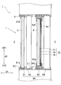
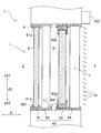
- FIG. 1 is a cross-sectional view showing the double window 1.
- 2 is a longitudinal sectional view of the double window 1 of FIG. 1, that is, a sectional view taken along the line II-II of FIG.
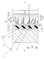
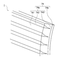
- FIG. 3A is an enlarged view of the deflection layer 74 in the double window 1 of FIG. 1 to 3A show an example in which a total reflection louver type deflection layer 74 is laminated on the indoor 3 side of the inner window 6.
- the double window 1 is installed in an opening 4 that opens toward the outdoor 2 and the indoor 3 between the adjacent outdoor 2 and the indoor 3.
- the outdoor 2 is an example of a first space
- the indoor 3 is an example of a second space.
- the double window 1 includes an outer window 5 that is an example of a first window and an inner window 6 that is an example of a second window.
- two outer windows 5 and two inner windows 6 are arranged.
- the inner window 6 is disposed on the indoor 3 side of the outer window 5 and can be moved relative to the outer window 5.
- Sunlight L is incident on the outer window 5 from the outdoor 2 side, and the incident sunlight L is emitted to the indoor 3 through the inner window 6.
- the double window 1 is provided with a light control sheet 70.
- light incident on the second space (indoor 3 in the figure) from the first space (outdoor 2 in the figure) is treated as sunlight.
- the present invention is not limited to this, and the incident light is derived from artificial light. It may be a thing.
- the outer window 5 and the inner window 6 are, for example, plate-like members made of glass or resin having visible light permeability.
- the thicknesses of the outer window 5 and the inner window 6 may be the same or different from each other. For example, the soundproofness can be improved by making the outer window 5 and the inner window 6 different in thickness.
- the light control sheet 70 is disposed on the surface 6a of the inner window 6 on the indoor 3 side, and has a sheet shape as a whole.
- the inner window 6 shown in FIGS. 1 to 3A is a single glass window.
- the light control sheet 70 is a sheet that does not have a protruding portion that protrudes greatly toward the indoor 3, thereby effectively avoiding the loss of the aesthetics of the opening 4, and double windows in various openings 4. 1 can be applied.
- the outer window 5 and the inner window 6 are held in the opening 4 by a holder 80.
- the holder 80 includes an outer window frame 81 that is an example of a first frame, an inner window frame 82 that is an example of a second frame, an outer window holder 83, and an inner window holder 84.
- the outer window holder 83 and the inner window holder 84 have rails 831 and 841 extending in a direction d2 (hereinafter referred to as a frontage direction) orthogonal to the opening direction d1 of the opening 4.
- the outer window 5 is held by the outer window holder 83 slidably, for example, slidable along the rail 831 with its outer peripheral edge held by the outer window frame 81.
- the inner window 6 is held by the inner window holder 84 so as to be movable along the rail 841, for example, slidable and removable, with a part or all of the outer peripheral edge thereof being held by the inner window frame 82.
- the inner window 6 may be, for example, rotatable (for example, inwardly opened or rotationally opened) or inclined (for example, inward) with respect to the outer window 5.
- the inner window 6 and the outer window 5 can move non-parallel to the opening direction d1 by being slidable along the rails 831 and 841 extending in the frontage direction d2.
- the inner window 6 may be fixed to the opening 4, while the outer window 5 may be attached to the opening 4 so as to be able to perform operations such as translation and rotation.
- the inner peripheries of the outer window frame 81 and the inner window frame 82 may be the same or different.
- the inner window frame 82 may have an inner circumference smaller than the outer window frame 81.
- the outer window frame 81 is difficult to enter the field of view, so that an aesthetic appearance can be ensured.
- the lower upper end 82 a of the inner window frame 82 is located above (d31 side) the lower upper end 81 a of the outer window frame 81.
- the reflected light L1 can be blocked by the inner window frame 82 so that the reflected light L1 irregularly reflected on the bottom surface of the outer window holder 83 (that is, the rail 831) or the bottom surface of the opening 4 does not travel to the indoor 3 side.
- the antiglare property can be improved.
- the upper lower end 82 b of the inner window frame 82 is positioned below (d32 side) than the upper lower end 81 b of the outer window frame 81.
- the upper lower end 82b of the inner window frame 82 is low so that the inner window 6 has an effect of eaves. I hardly receive it.
- the lower upper end 82a of the inner window frame 82 may be positioned above the lower upper end 81a of the outer window frame 81 in the range of 20 mm to 100 mm.
- the upper lower end 82b of the inner window frame 82 may be positioned below the upper lower end 81b of the outer window frame 81 in the range of 20 mm to 100 mm.
- the thickness of the air layer formed between the outer window 5 and the inner window 6 is not particularly limited, but may be within a range of 50 mm to 150 mm from the viewpoint of soundproofing and heat insulation, for example. Further, if air convection is generated inside the air layer, the heat insulation performance may be lowered. Therefore, in order to suppress the generation of convection, for example, it may be within a range of 50 mm to 80 mm.
- the thickness of an air layer refers to the space
- the outer window frame 81 and the inner window frame 82 may be formed of a material having lower thermal conductivity than a metal such as aluminum or a metal such as resin or wood.
- the outer window frame 81 and the inner window frame 82 may be formed by laminating metal, resin, and wood, or mixing wood with resin.
- the outer window frame 81 is formed of metal
- the inner window frame 82 is formed of resin.
- Both the outer window frame 81 and the inner window frame 82 may be formed of resin.
- the inner window frame 82 may be made of a material having high thermal conductivity so that latent heat generated in the deflection layer 74 described later can be easily released.
- the double window 1 may have a portion having an ultraviolet blocking function that absorbs or reflects ultraviolet rays on the outdoor 2 side of the deflection layer 74.
- the double window 1 may include a portion having a light diffusion function in the optical path from the outdoor 2 to the indoor 3 for incident light.
- the outdoor 2 side and / or the indoor 3 side of the deflecting layer 74. Includes a portion having a light diffusion function.
- the light control sheet 70 includes an ultraviolet absorbing adhesive layer 71 that is an example of a portion having an ultraviolet absorbing function, which is laminated on the surface 6 a of the inner window 6 on the indoor 3 side in the following order.
- the barrier layer 72, the first adhesive layer 73, the deflection layer 74, the second adhesive layer 75, and the light diffusion layer 76 which is an example of a portion having a light diffusion function.
- the ultraviolet absorbing function of the portion having the ultraviolet absorbing function for example, the light transmittance at a predetermined wavelength included in the wavelength range of 380 nm to 200 nm can be set to 5% or less. It is more preferable that the predetermined wavelength is included in a wavelength range of 380 nm to 300 nm because fading due to sunburn of furniture or goods caused by sunlight can be further suppressed.
- the light diffusion layer 76 can be omitted.
- the outer window 5 and / or the inner window 6 can be made of template glass, ground glass, frosted glass, or the like.
- the outer window 5 and the inner window 6 are an example of a portion having a light diffusion function provided on the outdoor 2 side of the deflection layer 74.
- the ultraviolet absorbing adhesive layer 71 can be omitted.
- a film having a function of reflecting or absorbing ultraviolet rays can be bonded to the outer window 5 and / or the inner window 6.
- the ultraviolet absorbing adhesive layer 71 is provided on the outdoor 2 side with respect to the deflection layer 74.
- the light control sheet 70 is fixed to the inner window 6 by the adhesive force of the ultraviolet absorbing adhesive layer 71.
- the ultraviolet absorbing pressure-sensitive adhesive layer 71 is, for example, an adhesive containing an ultraviolet absorber and having visible light permeability.
- the ultraviolet absorbing adhesive layer 71 absorbs the ultraviolet light L2 incident from the outdoor 2 side, thereby suppressing the ultraviolet light L2 from entering the deflection layer 74. Thereby, deterioration of the deflection layer 74 due to the ultraviolet ray L2 can be suppressed.
- the barrier layer 72 is fixed to the inner window 6 by the adhesive force of the ultraviolet absorbing adhesive layer 71.
- the barrier layer 72 is a film made of a resin such as PET (polyethylene terephthalate).
- PET polyethylene terephthalate
- the barrier layer 72 prevents the ultraviolet absorbent contained in the ultraviolet absorbing adhesive layer 71 from entering the deflection layer 74. Thereby, deterioration of the deflection
- the first adhesive layer 73 is, for example, an adhesive that does not contain an ultraviolet absorber and has visible light permeability.
- the deflection layer 74 is fixed to the barrier layer 72 by the adhesive force of the first adhesive layer 73.
- the deflection layer 74 is disposed on the indoor 3 side of the inner window 6.
- the deflection layer 74 is stacked on the inner window 6 so as to be movable relative to the outer window 5 together with the inner window 6.
- the deflection layer 74 deflects the visible light L3 incident from the outdoor 2 side and emits it to the indoor 3 side. That is, the deflection layer 74 has a daylighting function of adjusting the optical path of the light in the outdoor 2 and taking the light into the indoor 3.
- the deflection layer 74 in FIG. 3A includes a deflection layer main body 74a and a base material layer 74b.
- the base material layer 74b is, for example, a transparent or translucent resin film.
- the base material layer 74b is provided for manufacturing the deflection layer 74 in accordance with a manufacturing process described later.
- the base material layer 74b may be omitted.
- the deflection layer body 74 a includes a first portion 741, a second portion 742, and a third portion 743. Note that the third portion 743 is integrally formed with the first portion 741 using the same material as the first portion 741. Hereinafter, the first portion 741 and the third portion 743 are collectively referred to as an integral layer 744.
- the first portion 741 is bonded to the first adhesive layer 73 on the surface 741a on the outdoor two side.
- a plurality of substantially wedge-shaped grooves 741b are formed on the surface 741a of the first portion 741 at intervals in the vertical direction d3.
- Each groove 741b is formed in the first portion 741 over the entire region in the frontage direction d2 (see FIG. 1).
- the width of each groove 741b in the vertical direction d3 becomes narrower toward the indoor 3 side, that is, the third portion 743 side, and is finally closed in a state where the width is almost zero.
- the first portion 741 is made of a light transmissive material. This translucent material may be, for example, PET or acrylic resin.
- the second portion 742 is provided inside each groove 741b so as to fill each groove 741b.
- the second portion 742 has a shape that follows the groove 741b. Specifically, the second portion 742 has a side surface 742a, a steep slope 742b, a gentle slope 742c, and a bottom surface 742d.
- the side surface 742 a is flush with the surface 741 a of the first portion 741 and is bonded to the first adhesive layer 73.
- the steep slope 742b extends from the upper end of the side surface 742a toward the indoor 3 side, and is inclined downward d32 toward the indoor 3 side.
- the gentle slope 742c extends from the end of the steep slope 742b on the indoor 3 side toward the indoor 3 side, and is inclined downward d32 toward the indoor 3 side.
- the bottom surface 742d connects the lower end of the side surface 742a and the end of the gentle slope 742c on the indoor 3 side, that is, the lower end.
- the second portion 742 has a lower refractive index of visible light L3 than the first portion 741. Accordingly, the second portion 742 can totally reflect the visible lights L31 and L32 incident on the inclined surfaces 742b and 742c from the first portion 741 side, that is, the interface with the first portion 741 at an incident angle larger than the critical angle.
- the inclination angle ⁇ 1 of the steep slope 742b with respect to the opening direction d1 is larger than the inclination angle ⁇ 2 of the gentle slope 742c with respect to the opening direction d1.
- the inclination angle ⁇ 2 is 0 ° or more ( ⁇ 2 ⁇ 0). Since the inclination angle ⁇ 1 is larger than the inclination angle ⁇ 2, the steep slope 742b allows the visible light L31 from a high position on the outdoor 2 to enter at an incident angle larger than the critical angle, and the incident visible light L31 does not rise significantly and does not rise significantly. Total reflection is possible toward the back side of 3.
- the gentle slope 742c allows the visible light L32 from a low position in the outdoor 2 to be incident at an incident angle larger than the critical angle, and the incident visible light L32 does not rise significantly and does not rise significantly. Total reflection is possible toward the back side.
- the indoor 3 can be illuminated brightly. That is, the illumination effect of the light taken in can be improved.
- the visible lights L31 and L32 incident on the steep slope 742b or the gentle slope 742c are shown in a straight line, but in reality, they are refracted, that is, deflected every time they pass through interfaces having different refractive indexes.
- the second portion 742 has a main portion 742e that functions as an adhesive, and an optional functional material 742f dispersed in the main portion 742e.
- the main portion 742e is formed of a material having a lower refractive index than the first portion 741.
- the material of the main portion 742e may be a resin material, for example, an ionizing radiation curable resin that is cured by irradiation with ionizing radiation.
- the ionizing radiation curable resin may be, for example, an ultraviolet curable resin, an electron beam curable resin, a visible light curable resin, or a near infrared curable resin.
- the linear expansion coefficient of the main portion 742e is desirably the same as or close to the linear expansion coefficient of the first portion 741. By making the linear expansion coefficient of the main portion 742e the same as or close to the linear expansion coefficient of the first portion 741, separation of the second portion 742 from the first portion 741 due to thermal expansion of the main portion 742e can be suppressed.
- the functional inclusion 742f is dispersed in the main portion 742e in anticipation of various functions.
- a heat ray absorbing material may be employed as the functional inclusion 742f.
- the heat ray absorbing material may be, for example, transparent inorganic nanoparticles.
- Inorganic nanoparticles include, for example, antimony tin oxide (ATO), indium tin oxide (ITO), lanthanum hexaboride (LaB6), aluminum doped zinc oxide, indium doped zinc oxide, gallium doped zinc oxide, tungsten oxide, six It may be nanoparticles of cerium boride, anhydrous zinc antimonate and copper sulfide or a mixture thereof.
- ATO antimony tin oxide
- ITO indium tin oxide
- LaB6 lanthanum hexaboride
- Al doped zinc oxide aluminum doped zinc oxide
- indium doped zinc oxide gallium doped zinc oxide
- tungsten oxide six
- It may be nanoparticles of cerium boride, anhydrous zinc antimonate and copper sulfide or a mixture thereof.
- a coloring material may be employed as the functional content 742f.
- the colorant may be a pigment, and more specifically, a black pigment such as carbon black, graphite, or titanium nitride.
- the deflection layer 74 can exhibit the light blocking function of the visible light L3.
- bluish particles such as amber, blue, and purple, reddish particles, yellowish particles, and the like may be used as the colorant.
- the second portion 742 of the deflection layer 74 may be composed of two or more layers having different functions.
- the layer on the outdoor side of the second portion 742 may have a heat shielding function
- the layer on the indoor side of the second portion 742 may have a design function.
- the deflection layer 74 can be manufactured, for example, as follows. First, an integrated layer 744 of the first portion 741 and the third portion 743 is made of a material such as ionizing radiation curable epoxy acrylate. Specifically, a mold roll having a convex portion corresponding to the configuration (that is, arrangement, shape, etc.) of the groove 741b of the first portion 741 is prepared. Next, a sheet of the base material layer 74b is fed between the mold roll and the nip roll, and a curable material is supplied between the mold roll and the base material layer 74b in accordance with the feeding of the sheet.
- a material such as ionizing radiation curable epoxy acrylate.
- the curable material is pressed with a mold roll and a nip roll so that the liquid curable material supplied onto the base material layer 74b is filled in the concave portion of the mold roll.
- the surface 741a and the groove are formed on the curable material while securing the third portion 743 by supplying the curable material onto the base material layer 74b so that the mold roll and the base material layer 74b do not contact each other.
- the shape of 741b is transferred.
- the integral layer 744 is obtained by irradiating the curable resin with light to cure (solidify) the curable material.
- a liquid composition containing a curable material such as urethane acrylate that forms the main portion 742e by curing and a functional content 742f is supplied to the integrated layer 744.
- the composition is filled into each groove 741b of the first portion 741 using a doctor blade.
- the excess composition overflowing out of the groove 741b is scraped off with a doctor blade.
- the 2nd part 742 is obtained by irradiating ionizing radiation and hardening a composition. In this way, the deflection layer 74 having the base layer 74b and the deflection layer body 74a is manufactured.
- FIG. 3B is an enlarged view showing a modification of the deflection layer 74 of FIG. 3A.
- the deflection layer 74 may be inclined upward d31 as the bottom surface 742d moves toward the indoor 3 side.
- the deflecting layer 74 may be made of a material having a lower refractive index than the deflecting layer body 74a that does not include the functional inclusion 742f.
- the inclination angle ⁇ 1 of the steep slope 742b with respect to the opening direction d1 is larger than the inclination angle ⁇ 2 of the gentle slope 742c with respect to the opening direction d1.
- the inclination angle ⁇ 2 is 0 ° or more ( ⁇ 2 ⁇ 0).
- the inclination angle ⁇ 3 of the bottom surface 742d with respect to the opening direction d1 is smaller than ⁇ 1 ( ⁇ 1> ⁇ 3).
- the second adhesive layer 75 is, for example, an adhesive that does not contain an ultraviolet absorber and has visible light permeability.
- the light diffusion layer 76 is fixed to the deflection layer 74 by the adhesive force of the second adhesive layer 75.
- the light diffusion layer 76 is disposed on the indoor 3 side of the deflection layer 74.
- the light diffusion layer 76 diffuses the visible light L ⁇ b> 3 deflected by the deflection layer 74 and emits it to the indoor 3.
- the light diffusion layer 76 may be, for example, template glass, frosted glass, or frosted glass. According to the light diffusion layer 76, a diffused light distribution obtained by diffusing the visible light L3 deflected by the deflection layer 74 can be obtained, so that the indoor 3 can be illuminated uniformly and brightly. In addition, by providing the light diffusion layer 76, it is possible to reduce the glare that can be seen from the indoor side according to the repeated arrangement of the first portion 741 and the second portion 742 having different refractive indexes. .
- the double window 1 configured as described above can be assembled using, for example, a double window kit including the inner window 6, the light control sheet 70, the inner window frame 82, and the inner window holder 84 as follows. it can. In the following example, it is assumed that the outer window 5, the outer window frame 81, and the outer window holder 83 are already provided in the opening 4.
- the light control sheet 70 is affixed to the inner window 6 via the ultraviolet absorbing adhesive layer 71.
- the light control sheet 70 may be attached at any of the manufacturing stage of the inner window 6 and the assembly stage (that is, the construction stage) of the double window 1.
- the light control sheet 70 before being attached to the inner window 6 may have a release sheet attached to the ultraviolet absorbing adhesive layer 71.
- the inner window frame 82 is attached to the outer periphery of the inner window 6 and the light control sheet 70.
- the inner window frame 82 may be attached either before the assembly step to the opening of the double window 1 or during the assembly step to the opening of the double window 1.
- the inner window holder 84 is installed in the opening 4 so as to be adjacent to the outer window holder 83 on the indoor 3 side.
- the inner window holder 84 may be installed by fixing the inner window holder 84 to the opening 4 by screwing or the like. Next, the inner window 6 is fitted into the inner window holder 84 and attached.
- the double window 1 can be easily assembled by combining the existing outer window 5 and the double window kit.
- an auxiliary material called a fusible frame at the lower end on the indoor 3 side of the opening 4 May be installed.
- the inner window holder 84 is mounted substantially horizontally.
- the inner window 6 is attached to be within 3 ° from the horizontal.
- the reflection surface of the deflection layer 74 laminated on the inner window 6 may take an angle that is not intended in design. In such a case, the angle of the inner window 6 may be adjusted by disposing an angle adjusting attachment (not shown) below the inner window holder 84.
- the second portion 742 of the deflection layer 74 has a reflective surface that is asymmetric in a longitudinal sectional view.
- the inner window 6 is configured to be detachable from the inner window holder 84, it is asymmetrical by attaching the inner window 6 to the inner window holder 84 by turning it upside down in consideration of the incident angle of light and the necessity of daylighting. You may use a reflective surface properly.
- the sunlight L incident on the inner window 6 is incident on the ultraviolet absorbing adhesive layer 71 immediately after passing through the inner window 6.
- the ultraviolet L2 is absorbed by the ultraviolet absorbing adhesive layer 71 and hardly transmits. Since the ultraviolet ray L2 hardly passes through the ultraviolet absorbing adhesive layer 71, the incidence of the ultraviolet ray L2 on the deflection layer 74 located on the emission side of the ultraviolet absorbing adhesive layer 71 is suppressed. Thereby, deterioration of the deflection layer 74 due to the ultraviolet ray L2 can be suppressed.
- the visible light L3 passes through the ultraviolet absorbing adhesive layer 71 with almost no absorption.
- the visible light L3 that has passed through the ultraviolet absorbing adhesive layer 71 passes through the barrier layer 72 and the first adhesive layer 73 in order and then enters the deflection layer 74.
- the visible light L3 incident on the surface 741a of the first portion 741 travels inside the first portion 741, and has an interface 742b with the second portion 742 having a lower refractive index than the first portion 741. Incident to 742c.
- the steep slope 742b has a posture ( ⁇ 1> ⁇ 2) nearly parallel to the visible light L31 from a high position
- the visible light L31 from a high position is larger than the critical angle on the steep slope 742b. Easy to enter at an incident angle. Thereby, the visible light L31 from a high position can be reliably totally reflected by the steep slope 742b.
- the steep slope 742b is inclined downward d32, the total reflection direction by the steep slope 742b is close to the horizontal direction, that is, the opening direction d1. Thereby, the rising of visible light L31 from a high position can be suppressed, and visible light L31 can be totally reflected toward the back side of indoor 3.
- the gentle slope 742c has a posture ( ⁇ 2 ⁇ 0) that is nearly parallel to the visible light L32 from a low position, the visible light L32 from the low position is more than the critical angle on the gentle slope 742c. Easy to enter at a large incident angle. Thereby, the visible light L32 from a low position can be reliably totally reflected by the gentle slope 742c.
- the gentle slope 742c is inclined downward d32, the total reflection direction by the gentle slope 742c is close to the horizontal direction. Thereby, the rising of the visible light L32 from a low position is suppressed, and the visible light L32 can be totally reflected toward the back side of the indoor 3.
- the visible light L3 incident on the side surface 742a of the second portion 742 is incident on the functional content 742f and is affected by the functional content 742f.
- the functional inclusion 742f is a heat-absorbing material, the heat of visible light L3 can be absorbed and the transfer of heat to the indoor 3 side can be suppressed.
- the visible light L 3 emitted from the deflection layer 74 passes through the second adhesive layer 75 and enters the light diffusion layer 76.
- the visible light L3 incident on the light diffusion layer 76 is diffused and emitted to the indoor 3.
- the light from the outdoor 2 is deflected by the deflecting layer 74 and taken into the indoor 3, so that the illumination effect of the taken light can be improved while avoiding direct light.
- the light diffusion layer 76 can be omitted.
- the outer window 5 and / or the inner window 6 can be made of template glass, ground glass, frosted glass, or the like.
- the ultraviolet absorbing adhesive layer 71 can be omitted.
- a film having a function of reflecting or absorbing ultraviolet rays can be bonded to the outer window 5 and / or the inner window 6.
- the double window 1 of the present embodiment is not limited to the configuration shown in FIGS. 1 to 3A, and can be variously changed as shown in the following modifications.
- the same reference numerals as those used for the corresponding parts in the above embodiment are used for the parts that can be configured in the same manner as in the above embodiment.
- the duplicated explanation is omitted.
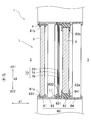
- FIG. 4 is a longitudinal sectional view showing an example in which a deflection layer 74 is laminated on the outdoor 2 side of the inner window 6 as the double window 1 according to the first modification.
- the light control sheet 70 is laminated in the following order on the surface 6b on the outdoor 2 side of the inner window 6, in the following order: an adhesive layer 202, a light diffusion layer 76, an adhesive layer 75, It has the hard coat layer 201 which is an example of the part which has the deflection
- the hard coat layer 201 has weather resistance, light transmissivity, and scratch resistance that hardly causes deterioration due to ultraviolet rays, heat, water, chemicals, temperature changes, and the like.
- the hard coat layer 201 may be formed, for example, by applying an electron beam curable transparent resin to which an ultraviolet absorber is added on the deflecting layer 74 and curing the applied transparent resin by electron beam irradiation.
- an ultraviolet adhesive layer 71 similar to that shown in FIG. 3A may be disposed between the hard coat layer 201 and the deflection layer 74.
- the ultraviolet absorbing adhesive layer 71 can be omitted, or the ultraviolet adhesive layer 71 and the outer window 5 having an ultraviolet blocking function can be used in combination.
- the inner window 6 instead of providing the light diffusion layer 76, the inner window 6 itself may have a light diffusion function.
- the inner window 6 may be a template glass, frosted glass, or frosted glass, or a light diffusing agent is dispersed in the inner window 6 or a layer having a light diffusing function is provided. Or you may.
- the visible light L3 can be deflected by the deflecting layer 74 and taken into the indoor 3 in the same way as the double window 1 of the above-described embodiment and modified example, so that direct light is reduced.
- the illumination effect of the light taken in can be improved.
- the visible light L3 deflected by the deflection layer 74 is diffused by the light diffusion layer 76, so that the indoor 3 can be illuminated brightly.
- the deterioration of the deflection layer 74 due to the ultraviolet ray L2 can be suppressed.
- the deflection layer 74 can be protected by the hard coat layer 201, the weather resistance of the deflection layer 74 can be improved. Further, in the first modified example, since the deflection layer 74 is disposed so as to avoid the indoor side, the chance of dirt adhering to the surface of the deflection layer 74 is reduced.
- FIG. 5 is a longitudinal sectional view showing an example in which a deflection layer 74 is laminated on the indoor 3 side of the outer window 5 as the double window 1 according to the second modification.
- FIG. 5 corresponds to a case in which the inner window 6 in FIG. That is, instead of laminating the light control sheet 70 shown in FIG. 3A on the surface of the inner window 6 on the indoor 3 side, the light control sheet 70 may be laminated on the surface of the outer window 5 on the indoor 3 side.
- the outer window 5 has an ultraviolet blocking function, the ultraviolet absorbing adhesive layer 71 can be omitted.
- the deflecting layer 74 is disposed on the outer window 5 side, not on the inner window 6 that is in contact with the indoor 3 and is likely to cause condensation. Therefore, it is possible to suppress the occurrence of mold on the deflection layer 74 or the occurrence of peeling due to condensation.
- the second modified example similarly to the double window 1 of the above-described embodiment and modified example, it is possible to improve the illumination effect of the light taken in while reducing the direct light by the deflection layer 74.
- the deflection layer 74 is arranged so as to avoid the indoor side, the chance that dirt adheres to the surface of the deflection layer 74 is reduced.
- FIG. 6 is a longitudinal sectional view showing an example in which a deflection layer 74 is laminated on the outdoor 2 side of the outer window 5 as the double window 1 according to the third modification.
- FIG. 6 corresponds to the first modified example (FIG. 4) in which the inner window 6 is replaced with the outer window 5. That is, instead of laminating the light control sheet 70 shown in FIG. 4 on the surface of the inner window 6 on the outdoor 2 side via the adhesive layer 202, the adhesive layer 202 is formed on the surface of the outer window 5 on the outdoor 2 side. You may laminate through. Further, in the example shown in FIG.
- the deflection layer 74 is disposed on the outdoor 2 side from the outer window 5, and thus is more easily deteriorated due to scratches and wind and rain than when disposed on the indoor 3 side. For this reason, on the outdoor 2 side of the deflection layer 74, a hard coat layer 201 having not only an ultraviolet absorbing function but also excellent scratch resistance and water resistance is disposed. By disposing the hard coat layer 201, deterioration of the deflection layer 74 due to scratches or wind and rain can be suppressed. Further, on the indoor 3 side of the deflection layer 74, a light diffusion layer 76 is arranged in the same manner as in the embodiment and the modification described above.
- the light diffusion layer 76 may be fixed to the deflection layer 74 via an adhesive layer, or may be coated on the deflection layer 74.
- the deflecting layer 74 is disposed on the outer window 5 side, not on the inner window 6 where the dew layer 74 is in contact with the indoor 3 and condensation is likely to occur. Therefore, it is possible to suppress the occurrence of mold on the deflection layer 74 or the occurrence of peeling due to condensation.
- FIG. 7 is a longitudinal sectional view showing an example in which a deflection layer 74 is arranged inside the inner window 6 as the double window 1 according to the fourth modification.
- the inner window 6 of the fourth modification is an embodiment of double-glazed glass, and the deflection layer 74 is combined with double-glazed glass.
- the inner window 6 of the fourth modified example includes, in order from the outdoor 2 side, a first inner window substrate 61, a light control sheet 70 having the configuration shown in FIG. 3A, an intermediate layer 63, and a second inner window. And a window substrate 62.
- at least one of the first inner window substrate 61 and the second inner window substrate 62 may be provided with a thermal barrier coating called a Low-E metal film.
- the first inner window substrate 61 and the second inner window substrate 62 are connected by a frame-shaped spacer 301 disposed between the peripheral portions of the inner window substrates 61 and 62.
- a sealant 302 is provided on the outer peripheral surface of the spacer 301.
- the intermediate layer 63 may be filled with an inert gas such as air or argon, or the intermediate layer 63 may be in a vacuum state.
- the deflection layer 74 is laminated on the first inner window substrate 61, but the deflection layer 74 in the second modification (see FIG. 4) is formed on the second inner window substrate 62. It may be laminated on top.
- the second window 6 including the deflection layer 74 has a configuration called a so-called pair glass as a whole, a pair of inner window substrates 61 and 62 whose relative positions are positioned and a gap is formed between them. have.
- the present invention is not limited to the illustrated example, and the inner window 6 may have a configuration called so-called laminated glass, and the intermediate layer 63 may be deleted. Further, the number of substrates constituting the inner window 6 may be three or more.
- the distance between the first inner window substrate 6 and the second inner window substrate 62 may be, for example, within 20 mm in consideration of heat insulation.
- the fourth modified example similarly to the double window 1 of the above-described embodiment and modified example, it is possible to improve the illumination effect of the light taken in while reducing the direct light by the deflection layer 74. Moreover, since the heat insulation effect can be enhanced by using the double-glazed glass, the energy consumption for operating the air conditioner can be suppressed.
- the deflection layer 74 or the light control sheet 70 is disclosed as a component different from the inner window 6 or the outer window 5
- at least one of the inner window 6 and the outer window 5 has two or more transparent plates.
- FIG. 8 is a longitudinal sectional view showing an example in which a deflection layer 74 is arranged inside the outer window 5 as the double window 1 according to the fifth modification.
- the inner window 6 was the aspect of multilayer glass
- the outer window 5 is the aspect of multilayer glass.
- FIG. 8 corresponds to a structure in which the first inner window substrate 61 in FIG. 7 is replaced with the first outer window substrate 51 and the second inner window substrate 62 in FIG. 7 is replaced with the second outer window substrate 52.
- the intermediate layer 63 may be deleted.
- the fifth modified example similarly to the double window 1 of the above-described embodiment and modified example, it is possible to improve the illumination effect of the light taken in while avoiding direct light by the deflection layer 74. Moreover, the energy consumption of an air conditioner can be reduced by improving the heat insulation effect of the double window 1.
- the deflection layer 74 may be disposed apart from the inner window 6 and the outer window 5.
- the deflection layer 74 may be provided with a gap with respect to the inner window 6 and the outer window 5, and may be movable relative to the inner window 6 and the outer window 5.
- the deflecting layer 74 may be configured to always face the outer window 5, or drawn out from a storage space (not shown) at the upper end or the lower end inside the opening 4 to be in time with the outer window 5. You may be comprised so that it may oppose. Thereby, the user can freely select the field of view.
- FIG. 9 is a longitudinal sectional view showing an example in which a deflection layer 74 is arranged on the outdoor 2 side of the outer window 5 through a gap as the double window 1 according to the sixth modification.
- the deflection layer 74 of the sixth modification is held by the holder 401 at the end of the opening 4 on the outdoor 2 side. More specifically, the deflection layer 74 is movable, for example, slidable along the rail 402 of the holder 401 extending in the frontage direction d2 in the frontage direction d2.
- the movement of the deflection layer 74 can be performed independently of the movement of the outer window 5 and the movement of the inner window 6.
- the holder 401 may be integrated with the outer window holder 83, and the deflection layer 74 may not be able to move relative to the outer window holder 83.
- the deflection layer 74 may be parallel to the outer window 5 and the inner window 6 or may be non-parallel. If standing, the position of the holder 401 may be adjusted, and the deflection layer 74 may be inclined with respect to the outer window 5 to be configured like a shade.
- the deflection layer 74 of the sixth modified example is disposed on the outdoor 2 side from the outer window 5, it is more likely to be deteriorated due to scratches or wind and rain than when disposed on the indoor 3 side. For this reason, on the outdoor 2 side of the deflection layer 74, a hard coat layer 201 having not only an ultraviolet absorbing function but also excellent scratch resistance and water resistance is disposed. By disposing the hard coat layer 201, deterioration of the deflection layer 74 due to scratches or wind and rain can be suppressed. Further, on the indoor 3 side of the deflection layer 74, a light diffusion layer 76 is arranged in the same manner as in the embodiment and the modification described above. The light diffusion layer 76 may be fixed to the deflection layer 74 via an adhesive layer, or may be coated on the deflection layer 74.
- the deflection layer 74 similarly to the double window 1 of the above-described embodiment and modified example, it is possible to improve the illumination effect of the light taken in while avoiding direct light by the deflection layer 74.
- the deflection layer 74 by arranging the deflection layer 74 on the outdoor 2 side of the outer window 5, light with a high incident angle can be deflected in the direction of a low incident angle, and reflection loss at the window surface can be minimized. More light amount of sunlight L can be taken in by the deflection layer 74.
- the deflection layer 74 is provided at a position on the outdoor side with respect to the outer window 5 with a gap from the inner window 6 and the outer window 5.
- An example is shown.
- the deflection layer 74 is provided at a position between the outer window 5 and the inner window 6 via a gap with respect to the inner window 6 and the outer window 5. It may be done.
- the deflecting layer 74 may be configured to always face the outer window 5 and the inner window 6, or may be drawn out from the storage space (not shown) at the upper or lower end inside the opening 4. You may be comprised so that it may oppose the window 5 and the inner window 6 timely. Thereby, the user can freely select the field of view.
- FIG. 10 is a longitudinal sectional view showing an example in which a deflection layer 74 is arranged on the indoor 3 side of the outer window 5 through a gap as the double window 1 according to the seventh modification. Further, in the double window 1 according to the seventh modified example, the deflection layer 74 is disposed on the outdoor 2 side of the inner window 6 from the inner window 6 via a gap. The deflection layer 74 of the seventh modified example is held by the holder 801 between the outer window 5 and the inner window 6 in the opening 4. More specifically, the deflection layer 74 is movable in the frontage direction d2 along the rail 802 of the holder 801 extending in the frontage direction d2, and is slidable.
- deviation layer 74 of FIG. 10 is 1 sheet sash, you may make it 2 sheets.
- a hard coat layer 201 containing an ultraviolet absorber is disposed on the outdoor 2 side of the deflecting layer 74 as in the sixth modified example (FIG. 9).
- a light diffusion layer 76 is disposed on the indoor 3 side of the deflection layer 74.
- the movement of the deflection layer 74 can be performed independently of the movement of the outer window 5 and the movement of the inner window 6.
- the holder 801 may be integrated with the inner window holder 84, and the deflection layer 74 may not be able to move relative to the outer window holder 83.
- the seventh modified example similarly to the double window 1 of the above-described embodiment and modified example, it is possible to improve the illumination effect of the light taken in while avoiding direct light by the deflection layer 74.
- the deflection layer 74 is located on the outdoor side of the outer window 5 or at a position between the outer window 5 and the inner window 6.
- An example is shown in which the inner window 6 and the outer window 5 are provided via gaps.
- the deflection layer 74 is provided at a position closer to the indoor side than the inner window 6 with respect to the inner window 6 and the outer window 5 via a gap.
- the deflecting layer 74 may be configured to always face the inner window 6, or may be drawn out from a storage space (not shown) at the upper or lower end inside the opening 4 to be in time with the inner window 6. You may be comprised so that it may oppose. Thereby, the user can freely select the field of view.
- FIG. 11 is a longitudinal sectional view showing an example in which a deflection layer 74 is disposed on the indoor 3 side of the inner window 6 through a gap as the double window 1 according to the eighth modification.
- the deflection layer 74 of the eighth modification is held by the holder 801 on the indoor side of the inner window 6 in the opening 4. More specifically, the deflection layer 74 is movable in the frontage direction d2 along the rail 802 of the holder 801 extending in the frontage direction d2, and is slidable.
- deviation layer 74 of FIG. 11 is 1 sheet sash, you may make it 2 sheets.
- a coat layer 201 is disposed.
- a light diffusion layer 76 is disposed on the indoor 3 side of the deflection layer 74.
- the movement of the deflection layer 74 can be performed independently of the movement of the outer window 5 and the movement of the inner window 6.
- the holder 801 may be integrated with the inner window holder 84, and the deflection layer 74 may not be able to move relative to the outer window holder 83.
- FIG. 12 is a perspective view showing a deflection layer 74 supported as a double window 1 according to a ninth modification so as to be rotatable about a predetermined axis.
- the deflection layer 74 of the ninth modification includes a louver type deflection layer (see FIG. 3A and the like) that deflects light by total reflection, a louver type deflection layer (see FIG. 20) that deflects light by specular reflection, and a prism type.
- the deflection layer (see FIG. 18) and the craze type deflection layer (see FIG. 19) may be used.
- the deflection layer 74 of the ninth modification is supported rotatably about an axis extending in the frontage direction d2.
- the double window 1 according to the fourteenth modification includes a support shaft member 142 connected to the deflection layer 74 and a drive device 143 capable of driving the support shaft member 142.
- the support shaft member 142 extends in the frontage direction d2.
- the orientation of the deflection layer 74 can be adjusted according to the installation position, time, time, and the like.
- deviation layer 74 can exhibit scheduled functions, such as a daylighting function, a light shielding function, a heat shielding function, with respect to sunlight irrespective of time and time.
- the orientation of the deflection layer 74 is adjusted so that the bottom surface 742d of the deflection layer 74 in FIG.
- FIG. 12 the specific configuration shown in FIG. 12 is merely an example of a support method that allows the orientation of the deflection layer 74 to be varied.
- FIGS. 13 to 16 show another example of a configuration for supporting the deflection layer 74 so that the orientation of the deflection layer 74 can be changed as a tenth modification.
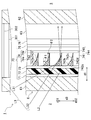
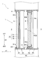
- FIG. 13 is a longitudinal sectional view showing an example in which a deflection layer 74 is arranged on the indoor 3 side of the inner window 6 through a gap as the double window 1 according to the tenth modification.
- FIG. 14 is a perspective view showing a double window 1 according to a tenth modification.
- FIG. 15 is an enlarged perspective view of the deflection layer 74 in the double window 1 of the tenth modification.
- the main portion 742e and the functional inclusion 742f (see FIG. 3A) constituting the second portion 742 are not shown.
- the double window 1 of the tenth modification includes a plurality of strip-shaped deflection layers 74 arranged in the vertical direction d ⁇ b> 3 and each deflection layer 74 so that the orientation of each deflection layer 74 can be changed.
- a support member 101 that supports In the tenth modification the deflection layer 74 has a so-called blind mode.
- the deflection layer 74 is arranged at a position facing the inner window 6 on the indoor 3 side.
- the deflection layer 74 of the tenth modified example is also called a slat or a blade plate, and is formed as a thin plate-like member that is elongated in the frontage direction d2.
- the deflection layer 74 of the tenth modification is formed in a slightly curved thin plate shape.
- the double window 1 of the tenth modified example has a mounting box 102, a ladder cord 103, a lifting / lowering cord 104, and an operation grip 105.
- the attachment box 102 is a fixture for attaching the deflection layer 74 to the wall.
- the ladder cord 103 hangs down from the mounting box 102 and supports each deflecting layer 74 in a state of being spaced apart in the vertical direction d3.
- the lifting / lowering cord 104 can pull up the deflection layer 74.
- the operation grip 105 is connected to the lifting / lowering cord 104, the ladder cord 103 and the lifting / lowering cord 104.
- the ladder code 103 controls the direction of each deflection layer 74, that is, the normal direction of the sheet surface of each deflection layer 74, so that each deflection layer 74 is substantially parallel.
- the direction of the deflection layer 74 can be adjusted.
- the direction of each deflection layer 74 is changed so as to rotate about an axis parallel to the longitudinal direction d2.
- each deflection layer 74 can be pulled up so as to narrow the interval in the vertical direction d3 sequentially from the deflection layer 74 on the lower d32 side. At this time, at least a part of each deflection layer 74 is accommodated in the mounting box 102, and the inner window 6 is exposed to the indoor 3. Similarly, by operating the lifting / lowering cord 104 via the operation grip 105, the deflection layer 74 gathered upward can be lowered to a position facing the inner window 6.
- the deflection layer 74 when the sheet surface of the deflection layer 74 extends substantially in the vertical direction d3, various functions expected for the deflection layer 74 with respect to sunlight L from the outdoors 2, for example, A lighting function, a light shielding function, a heat shielding function, etc. can be exhibited.
- the deflection layer 74 is changed with respect to the sunlight L from the sun whose altitude is changed by changing the direction of all the deflection layers 74 using the ladder code 103. Effectively perform planned functions.
- FIG. 16 is a longitudinal sectional view showing a deflecting layer 74 in a different direction from FIG. 13 in the tenth modification.
- the direction of the deflection layer 74 may be adjusted as shown in FIG. 16 so that the sunlight L passes between the neighboring deflection layers 74.
- this method compared with the case where sunlight L permeate
- the 2nd part 742 contains the functional substance 742f (refer FIG. 3A) which has visible-light-shielding property, in the state shown by FIG. It is also possible to prevent peeping from the opening direction d1.
- the light from the outdoor 2 is deflected by the deflecting layer 74 and taken into the indoor 3 so that the direct light can be obtained. While avoiding, the illumination effect of the light taken in can be improved.
- the deflection layer 74 has a daylighting function, a light shielding function, a heat shielding function, etc. The planned function can be demonstrated.
- the deflection layer 74 illustrated in the embodiment and the modification described above has a size facing the entire area of the outer window 5 and the inner window 6.
- the present invention is not limited to this example, and the deflection layer 74 may be disposed only in a part of the region facing the outer window 5 or may be disposed only in a part of the region facing the inner window 6. Good.
- FIG. 17 is a longitudinal sectional view showing an example in which the deflection layer 74 is partially arranged on the inner window 6 and the outer window 5 as the double window 1 according to the eleventh modification.
- the deflection layer 74 is disposed in a region facing the upper half of the outer window 5 and a region facing the lower half of the inner window 6. More specifically, the deflection layer 74 shown in FIG. 17 is partially laminated on the surface 5 a on the indoor 3 side of the outer window 5 and the surface 6 a on the indoor 3 side of the inner window 6.
- the deflection layer 74 of FIG. 17 is laminated on the upper half of the surface 5a of the outer window 5 and the lower half of the surface 6a of the inner window 6, it is not limited to such a configuration.
- the deflection layer 74 may be laminated on the lower half of the surface 5 a of the outer window 5 and the upper half of the surface 6 a of the inner window 6. Further, the deflection layer 74 may be laminated at the central portion in the vertical direction d3 of the surface 5a of the outer window 5 or the surface 6a of the inner window 6. By arranging the deflection layer 74 at the center of the outer window 5 or the inner window 6 in the vertical direction d3, it is deflected from below the height of the human line of sight, depending on the height of the opening 4 and the depth in the frontage direction.
- the deflection layer 74 may be partially laminated on the surface 5 b on the outdoor 2 side of the outer window 5 and the surface 6 b on the outdoor 2 of the inner window 6. Further, the deflection layer 74 may be partial to the surfaces 5a and 5b of the outer window 5 and the surfaces 6a and 6b of the inner window 6 not only in the vertical direction d3 but also in the frontage direction d2. Good.
- the deflection layer 74 having a size that is partially projected on the inner window 6 and the outer window 5 in the opening direction d1 is provided on the outdoor 2 side of the outer window 5, between the outer window 5 and the inner window 6, or on the inner side. You may arrange
- the illumination effect of the light taken in while avoiding direct light by the deflection layer 74 can be improved.
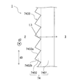
- FIG. 18 is a longitudinal sectional view showing a prism type deflection layer 74 as the double window 1 according to the twelfth modification.
- the deflection layer 74 of the twelfth modification is a prism form.
- the deflection layer 74 has a prism surface 7400, and deflects the visible light L ⁇ b> 3 by reflection or refraction at the prism surface 7400 to be taken into the indoor 3.
- the deflection layer 74 of the twelfth modification has a sheet-like main body portion 7401 and a plurality of unit prisms 7402 arranged on the main body portion 7401.
- the main body portion 7401 and the unit prism 7402 are made of a translucent material.
- the unit prisms 7402 are arranged in the vertical direction d3 and extend in the frontage direction d2.
- Each unit prism 7402 is arranged on one surface of the main body portion 7401 without any gap.
- the unit prism 7402 has a first surface 7402a and a second surface 7402b arranged to face each other in the vertical direction d3.
- the deflection layer 74 reflects, in particular, totally reflects the visible light L3 incident on the unit prism 7402 from one of the first surface 7402a and the second surface 7402b on the other of the first surface 7402a and the second surface 7402b. Accordingly, the deflection layer 74 can deflect the visible light L3 and emit it to the indoor 3 side.
- the illumination effect of the light taken in while avoiding the direct light can be improved by the deflection layer 74 as in the double window 1 of the embodiment and the modification described above. Further, according to the twelfth modification, the number of parts of the deflection layer 74 can be reduced by configuring the deflection layer 74 with a prism.
- FIG. 19 is a longitudinal sectional view showing a craze-type deflection layer 74 as the double window 1 according to the thirteenth modification.
- the deflection layer 74 of the thirteenth modification is a craze mode.
- the term “craze” (sometimes referred to as “craze”) refers to a substantially linear crack or crack formed in a resin film.
- the craze in the thirteenth modified example is one in which resin fibrils (that is, fibrous resin) remain between the wall surfaces of cracks or cracks formed in the resin film, and no resin fibrils remain. It is different from a crack.
- the deflection layer 74 of the thirteenth modification has a main body portion 7410 made of a resin film and a plurality of crazes 7411 formed on the surface 7410 a on the outdoor 2 side of the main body portion 7410.
- the craze 7411 is, for example, a straight plate with a sharp tip such as a blade or blade, and can be obtained by imparting a minute bending deformation along the straight line to the resin film.
- the visible light L3 incident on the craze 7411 of the deflecting layer 74 travels in the craze 7411 and then the resin fibril 7411a (that is, the high refractive index layer). It is incident on the gap 7411b (that is, the low refractive index layer).
- the gap 7411b that is, the low refractive index layer.
- FIG. 19 only one gap 7411b is representatively shown.
- the illumination effect of the light taken in can be improved by reducing the direct light by the deflection layer 74.
- the number of parts of the deflection layer 74 can be reduced by configuring the deflection layer 74 with crazes.
- FIG. 20 is a longitudinal sectional view showing a mirror louver type deflection layer 74 as the double window 1 according to the fourteenth modification.
- the deflection layer 74 of the twelfth modification has a plurality of blades 7415 arranged at intervals in the vertical direction d3. Each blade 7415 deflects the visible light L3 toward the indoor 3 side by specularly reflecting the visible light L3 on its upper surface 7415a.
- the deflection layer 74 shown in FIG. 20 is prepared by preparing a transparent base material with a cut 7416 and then filling the transparent base cut 7416 with a high reflectivity material such as aluminum. obtain.
- the upper surface 7415a of the blade 7415 is formed of a high reflectivity material such as aluminum.
- the blade 7415 may be formed as a gap. In this example, total reflection due to the difference in refractive index between the transparent substrate and the blade 7415 made of a gap can be caused, and a deflection function that does not cause reflection loss due to total reflection can be expected.
- FIG. 21 is a longitudinal sectional view showing an example in which an angle-dependent light control sheet 7420 is arranged on the indoor 3 side of the deflection layer 74 as the double window 1 according to the fifteenth modification.
- a deflection layer 74 is laminated on the outer window 5
- an angle-dependent light control sheet 7420 is laminated on the inner window 6.
- the angle-dependent light control sheet 7420 selectively scatters only incident light from a predetermined angle range and transmits other incident light.
- the angle-dependent light control sheet 7420 maintains a resin composition containing at least two types of photopolymerizable oligomers or monomers in a film form, and cures the film form body by irradiating ultraviolet rays from a predetermined direction. You may form by doing.
- the angle-dependent light control sheet 7420 of the fifteenth modified example has an optical characteristic of scattering the visible light L3 incident from obliquely above at an angle of a predetermined angle or more. Further, the angle-dependent light control sheet 7420 has an optical characteristic of transmitting visible light incident from obliquely above at an angle less than a predetermined angle, visible light incident from the horizontal direction, and visible light incident from obliquely below.
- the visible light L3 incident on the deflection layer 74 can travel obliquely downward toward the indoor 3 side.
- the visible light L3 traveling obliquely downward may become glare and feel dazzling.
- the visible light L3 traveling obliquely downward can be scattered by the angle-dependent light control sheet 7420. Thereby, the glare resulting from the visible light L3 which progresses diagonally downward can be suppressed.
- the illumination effect of the light taken in while avoiding direct light can be improved by the deflection layer 74. Further, the glare can be suppressed by scattering the visible light L3 that could not be appropriately deflected by the deflection layer 74 by the angle-dependent light control sheet 7420.
- FIG. 22 is a longitudinal sectional view showing an example in which the deflection layer 74 is reinforced as the double window 1 according to the sixteenth modification.
- the outer peripheral edge of the light control sheet 70 that is, the deflection layer 74 is covered with the covering material 151
- the outer peripheral edges of the light control sheet 70 and the windows 5 and 6 are window frames. 81, 82.
- the covering material 151 is formed of, for example, a silicone resin, an acrylic resin, a urethane resin, a polysulfide resin, and a mixture thereof.
- the covering material 151 may be disposed not only to cover the boundary between the substrate and the deflection layer 74 but also to run on the deflection layer 74.
- FIG. 22 shows a mode in which the end portion of the deflection layer 74 is accommodated in the window frames 81 and 82.
- this modification is not limited to this.
- the deflection layer 74 is attached to the existing outer window 5 and inner window 6 later, the end of the deflection layer 74 may not be accommodated in the window frames 81 and 82.
- the boundary between the substrate and the deflection layer 74 can be covered by disposing the covering material 151 along the periphery of the deflection layer 74 so as to cover the boundary between the substrate and the deflection layer 74.
- the coating material 151 can suppress the intrusion of moisture, foreign matter, and the like into the deflection layer 74, so that the deterioration of the deflection layer 74 and the peeling of the deflection layer 74 can be suppressed.
Landscapes
- Engineering & Computer Science (AREA)
- Structural Engineering (AREA)
- Civil Engineering (AREA)
- Physics & Mathematics (AREA)
- Architecture (AREA)
- General Physics & Mathematics (AREA)
- Optics & Photonics (AREA)
- Optical Elements Other Than Lenses (AREA)
Abstract
A double window (1) is arranged between a first space (2) and a second space (3) in an open section (4) that is open to the first space (2) and the second space (3). The double window (1) is provided with: a first window (5); and a second window (6) that is arranged closer to the second space (3) than the first window (5) and that can be relatively moved with respect to the first window (5). A polarizing layer (74) is provided that polarizes light that is incident from the first space (2) side, and allows the polarized light to be emitted to the second space (3) side.
Description
本開示は、開口部に配置される二重窓に関する。また、本開示は、二重窓の組立キット、二重窓の製造方法に関する。
The present disclosure relates to a double window disposed in an opening. The present disclosure also relates to a double window assembly kit and a double window manufacturing method.
窓のサッシを2組用いて断熱効果を高めた二重窓に関する技術が提案されている。例えば、JP1993-125869Aには、外窓と内窓とを備えた二重窓において、外窓に後付可能な内窓が開示されている。
A technology related to double windows that uses two sets of window sashes to enhance the heat insulation effect has been proposed. For example, JP1993-125869A discloses an inner window that can be retrofitted to an outer window in a double window having an outer window and an inner window.
しかしながら、JP1993-125869Aにおいては、屋内への直達光を減らしながら、屋外から採り込んだ光を屋内照明として利用することに関して、何ら有効な提案がなされていない。
However, in JP1993-125869A, no effective proposal has been made regarding the use of light taken from outside as indoor lighting while reducing direct light to the indoor.
本発明が解決しようとする課題は、直達光を回避しつつ、採り込んだ光の照明効果を向上できる二重窓およびその組立キット、製造方法ならびに設置方法を提供することである。
The problem to be solved by the present invention is to provide a double window, an assembly kit thereof, a manufacturing method and an installation method capable of improving the illumination effect of the light taken in while avoiding direct light.
上記の課題を解決するために、本発明の一態様では、
第1空間と第2空間との間において前記第1空間及び前記第2空間に向けて開口した開口部に配置される二重窓であって、
第1窓と、
前記第1窓よりも前記第2空間側に配置され、前記第1窓に対して相対移動可能な第2窓と、を備え、
前記第1空間側から入射した光を偏向して前記第2空間側に出射する偏向層が設けられている、二重窓が提供される。 In order to solve the above problems, in one embodiment of the present invention,
A double window disposed in an opening that opens toward the first space and the second space between the first space and the second space;
A first window;
A second window disposed on the second space side of the first window and movable relative to the first window;
A double window is provided in which a deflection layer is provided that deflects light incident from the first space side and emits the light to the second space side.
前記偏向層は、前記第2窓よりも第2空間側に配置されてもよい。
The deflection layer may be disposed on the second space side with respect to the second window.
前記偏向層は、前記第2窓とともに前記第1窓に対して相対移動可能に前記第2窓に積層されていてもよい。
The deflection layer may be stacked on the second window so as to be movable relative to the first window together with the second window.
前記偏向層は、前記第2窓に空隙を介して配置されてもよい。
The deflection layer may be disposed in the second window via a gap.
前記偏向層は、前記第1窓と前記第2窓との間に配置されてもよい。
The deflection layer may be disposed between the first window and the second window.
前記偏向層は、前記第2窓とともに前記第1窓に対して相対移動可能に前記第2窓に積層されていてもよい。
The deflection layer may be stacked on the second window so as to be movable relative to the first window together with the second window.
前記偏向層は、前記第2窓に空隙を介して配置されてもよい。
The deflection layer may be disposed in the second window via a gap.
前記偏向層よりも前記第1空間側または第2空間側に、光拡散機能を有する部分が設けられていてもよい。
A portion having a light diffusion function may be provided on the first space side or the second space side with respect to the deflection layer.
前記偏向層よりも前記第1空間側に、紫外線吸収機能を有する部分が設けられていてもよい。
A portion having an ultraviolet absorption function may be provided on the first space side of the deflection layer.
前記光拡散機能を有する部分は、前記第2窓に含まれている又は積層されていてもよい。
The portion having the light diffusion function may be included in or stacked on the second window.
前記紫外線吸収機能を有する部分は、前記第1窓に含まれている又は積層されていてもよい。
The portion having the ultraviolet absorbing function may be included in or stacked on the first window.
前記第1窓及び前記第2窓は、前記開口部の開口方向に非平行に移動可能であってもよい。
The first window and the second window may be movable non-parallel to the opening direction of the opening.
前記二重窓は、前記開口部に前記第1窓及び前記第2窓を保持可能な保持具を備え、
前記保持具は、前記第1窓に対して相対移動可能に前記第2窓を保持してもよい。 The double window includes a holder capable of holding the first window and the second window in the opening,
The holder may hold the second window so as to be movable relative to the first window.
前記保持具は、前記第1窓に対して相対移動可能に前記第2窓を保持してもよい。 The double window includes a holder capable of holding the first window and the second window in the opening,
The holder may hold the second window so as to be movable relative to the first window.
前記二重窓は、
前記第1窓の外周縁を保持する第1枠と、
前記第2窓の外周縁を保持する第2枠と、を備え、
前記第2枠は、前記第1枠よりも内周が小さくてもよい。 The double window is
A first frame for holding an outer peripheral edge of the first window;
A second frame for holding an outer peripheral edge of the second window,
The second frame may be smaller in inner circumference than the first frame.
前記第2枠の下部上端は、前記第1枠の下部上端よりも上方に位置してもよい。
The lower upper end of the second frame may be located above the lower upper end of the first frame.
前記第2枠の上部下端は、前記第1枠の上部下端よりも下方に位置してもよい。
The upper lower end of the second frame may be positioned below the upper lower end of the first frame.
本発明の他の一態様では、
第1空間と第2空間との間において前記第1空間および前記第2空間に向けて開口した開口部に配置された第1窓との組み合わせで二重窓を組み立てるための二重窓の組立キットであって、
前記第1窓よりも前記第2空間側に配置される第2窓と、
前記第1窓に対して相対移動可能に前記開口部に前記第2窓を保持する保持具と、を備え、
前記第2窓は、前記第1空間側から入射した光を偏向して前記第2空間側に出射する偏向層を含む、組立キットが提供される。 In another aspect of the invention,
Assembly of a double window for assembling a double window in combination with a first window disposed in an opening opened toward the first space and the second space between the first space and the second space A kit,
A second window disposed closer to the second space than the first window;
A holder that holds the second window in the opening so as to be movable relative to the first window;
An assembly kit is provided in which the second window includes a deflection layer that deflects light incident from the first space side and emits the light to the second space side.
本発明の他の一態様では、
前記二重窓を製造する二重窓の製造方法であって、
前記第1窓及び前記第2窓を支持する保持具を前記開口部に設置する工程と、
前記第1窓及び前記第2窓を前記保持具に取り付ける工程と、を備える、二重窓の製造方法が提供される。 In another aspect of the invention,
A method of manufacturing a double window for manufacturing the double window,
Installing a holder for supporting the first window and the second window in the opening;
Attaching the first window and the second window to the holder.
本発明の他の一態様では、
前記二重窓を開口部に設置する工程を備える、二重窓の設置方法が提供される。 In another aspect of the invention,
A method for installing a double window is provided, comprising the step of installing the double window in an opening.
前記二重窓を開口部に設置する工程を備える、二重窓の設置方法が提供される。 In another aspect of the invention,
A method for installing a double window is provided, comprising the step of installing the double window in an opening.
本発明によれば、直達光を減らしつつ、採り込んだ光の照明効果を向上できる。
According to the present invention, it is possible to improve the illumination effect of light taken in while reducing direct light.
以下、図面を参照して本発明の実施形態について説明する。なお、本明細書に添付する図面においては、図面の理解のしやすさの便宜上、適宜縮尺および縦横の寸法比等を、実物のそれらから変更し誇張している場合がある。
Hereinafter, embodiments of the present invention will be described with reference to the drawings. Note that, in the drawings attached to this specification, for convenience of understanding of the drawings, the scale and the vertical / horizontal dimensional ratio may be appropriately changed and exaggerated from those of the actual ones.
また、本明細書において用いる、形状や幾何学的条件並びにそれらの程度を特定する、例えば、「平行」、「直交」、「同一」等の用語については、厳密な意味に縛られることなく、同様の機能を期待し得る程度の範囲を含めて解釈することとする。
Further, as used in the present specification, the shape and geometric conditions and the degree thereof are specified, for example, terms such as “parallel”, “orthogonal”, “identical”, etc. are not limited to strict meanings, Interpretation should include the extent to which similar functions can be expected.
また、本明細書における「上下方向」は、鉛直方向に平行な面内において水平方向と非平行な方向であり、必ずしも鉛直方向とは一致しない。「上」とは、上下方向における一方であって、鉛直方向における「上」に近接する側(又は方)のことを指す。「下」とは、上下方向における「上」とは反対の側であって、鉛直方向における「下」に近接する側(又は方)のことを指す。
In addition, the “vertical direction” in this specification is a direction that is not parallel to the horizontal direction in a plane parallel to the vertical direction, and does not necessarily match the vertical direction. “Upper” means one side in the vertical direction and the side (or direction) close to “upper” in the vertical direction. “Lower” refers to a side (or direction) opposite to “upper” in the vertical direction and close to “lower” in the vertical direction.
また、本明細書において、「シート」、「フィルム」、「板」等の用語は、呼称の違いのみに基づいて、それぞれ区別されるものではない。したがって、例えば、「シート」はフィルムや板と呼ばれ得るような部材も含む概念である。
Also, in this specification, terms such as “sheet”, “film”, and “plate” are not distinguished from each other only based on the difference in names. Therefore, for example, a “sheet” is a concept including a member that can be called a film or a plate.
図1~図3Aは、本発明による一実施の形態を説明するための図である。このうち図1は、二重窓1を示す横断面図である。図2は、図1の二重窓1の縦断面図すなわち図1のII-II断面図である。図3Aは、図2の二重窓1における偏向層74の拡大図である。図1~図3Aは、内窓6の屋内3側に全反射ルーバ型の偏向層74を積層した例を示す。
1 to 3A are diagrams for explaining an embodiment according to the present invention. Among these, FIG. 1 is a cross-sectional view showing the double window 1. 2 is a longitudinal sectional view of the double window 1 of FIG. 1, that is, a sectional view taken along the line II-II of FIG. FIG. 3A is an enlarged view of the deflection layer 74 in the double window 1 of FIG. 1 to 3A show an example in which a total reflection louver type deflection layer 74 is laminated on the indoor 3 side of the inner window 6.
図1~図3Aに示すように、二重窓1は、隣り合う屋外2と屋内3との間において屋外2及び屋内3に向けて開口した開口部4に設置されるものである。屋外2は、第1空間の一例であり、屋内3は、第2空間の一例である。二重窓1は、第1窓の一例である外窓5と、第2窓の一例である内窓6とを備えている。図1および図2の例において、外窓5および内窓6は、2枚ずつ配置されている。
As shown in FIG. 1 to FIG. 3A, the double window 1 is installed in an opening 4 that opens toward the outdoor 2 and the indoor 3 between the adjacent outdoor 2 and the indoor 3. The outdoor 2 is an example of a first space, and the indoor 3 is an example of a second space. The double window 1 includes an outer window 5 that is an example of a first window and an inner window 6 that is an example of a second window. In the example of FIGS. 1 and 2, two outer windows 5 and two inner windows 6 are arranged.
内窓6は、外窓5よりも屋内3側に配置されており、外窓5に対して相対移動可能である。外窓5には、屋外2側から太陽光Lが入射し、入射した太陽光Lは内窓6を通して屋内3に出射される。屋内3への直達光を減らし、採光された光の照明効果を向上するため、二重窓1には、光制御シート70が設けられている。なお、本実施形態では第1空間(図示では屋外2)側から第2空間(図示では屋内3)に入射する光を太陽光として取り扱うが、これに限らず、入射光が人工光に由来するものであってもよい。外窓5および内窓6は、例えば、可視光透過性を有したガラスまたは樹脂からなる板状の部材である。外窓5および内窓6の厚みは、同一であってもよいし、互いに異なっていてもよい。例えば、外窓5および内窓6の厚みを異ならせることで、防音性を向上させることができる。
The inner window 6 is disposed on the indoor 3 side of the outer window 5 and can be moved relative to the outer window 5. Sunlight L is incident on the outer window 5 from the outdoor 2 side, and the incident sunlight L is emitted to the indoor 3 through the inner window 6. In order to reduce the direct light to the indoor 3 and improve the illumination effect of the collected light, the double window 1 is provided with a light control sheet 70. In this embodiment, light incident on the second space (indoor 3 in the figure) from the first space (outdoor 2 in the figure) is treated as sunlight. However, the present invention is not limited to this, and the incident light is derived from artificial light. It may be a thing. The outer window 5 and the inner window 6 are, for example, plate-like members made of glass or resin having visible light permeability. The thicknesses of the outer window 5 and the inner window 6 may be the same or different from each other. For example, the soundproofness can be improved by making the outer window 5 and the inner window 6 different in thickness.
図2および図3Aに示すように、光制御シート70は、内窓6の屋内3側の表面6aに配置されており、全体としてシート状を有している。なお、図1~図3Aに示される内窓6は、1枚のガラス窓である。光制御シート70が屋内3に向けて大きく突出する突出部を有しないシート状であることで、開口部4の美感を損なうことを効果的に回避しながら、種々の開口部4に二重窓1を適用できる。
2 and 3A, the light control sheet 70 is disposed on the surface 6a of the inner window 6 on the indoor 3 side, and has a sheet shape as a whole. The inner window 6 shown in FIGS. 1 to 3A is a single glass window. The light control sheet 70 is a sheet that does not have a protruding portion that protrudes greatly toward the indoor 3, thereby effectively avoiding the loss of the aesthetics of the opening 4, and double windows in various openings 4. 1 can be applied.
図1および図2に示すように、外窓5および内窓6は、保持具80によって開口部4に保持されている。保持具80は、第1枠の一例である外窓枠81と、第2枠の一例である内窓枠82と、外窓ホルダ83と、内窓ホルダ84とを備える。外窓ホルダ83および内窓ホルダ84は、開口部4の開口方向d1に直交する方向(以下、間口方向と呼ぶ)d2に延びるレール831、841を有する。外窓5は、その外周縁を外窓枠81で保持された状態で、レール831に沿って移動可能、例えば摺動可能に外窓ホルダ83に保持されている。内窓6は、その外周縁の一部又は全部を内窓枠82で保持された状態で、レール841に沿って移動可能、例えば、摺動可能、取り外し可能に内窓ホルダ84に保持されている。内窓6は、外窓5に対して、例えば、回転可能(例えば、内開き、回転開き)、傾斜可能(例えば、内倒し)であってもよい。また、間口方向d2に延びるレール831、841に沿って摺動可能であることで、内窓6および外窓5は、開口方向d1に非平行に移動できる。なお、内窓6が開口部4に固定され、その一方で外窓5が並進、回転等の動作が可能なように開口部4に取付けられていてもよい。
As shown in FIGS. 1 and 2, the outer window 5 and the inner window 6 are held in the opening 4 by a holder 80. The holder 80 includes an outer window frame 81 that is an example of a first frame, an inner window frame 82 that is an example of a second frame, an outer window holder 83, and an inner window holder 84. The outer window holder 83 and the inner window holder 84 have rails 831 and 841 extending in a direction d2 (hereinafter referred to as a frontage direction) orthogonal to the opening direction d1 of the opening 4. The outer window 5 is held by the outer window holder 83 slidably, for example, slidable along the rail 831 with its outer peripheral edge held by the outer window frame 81. The inner window 6 is held by the inner window holder 84 so as to be movable along the rail 841, for example, slidable and removable, with a part or all of the outer peripheral edge thereof being held by the inner window frame 82. Yes. The inner window 6 may be, for example, rotatable (for example, inwardly opened or rotationally opened) or inclined (for example, inward) with respect to the outer window 5. Moreover, the inner window 6 and the outer window 5 can move non-parallel to the opening direction d1 by being slidable along the rails 831 and 841 extending in the frontage direction d2. The inner window 6 may be fixed to the opening 4, while the outer window 5 may be attached to the opening 4 so as to be able to perform operations such as translation and rotation.
外窓枠81および内窓枠82の内周は、同一であってもよいし、異なっていてもよい。例えば、図1および図2に示すように、内窓枠82は、外窓枠81よりも内周が小さくてもよい。これにより、屋内3側から屋外2を見た場合に外窓枠81が視界に入り難いので、美観を確保できる。また、図2に示すように、内窓枠82の下部上端82aは、外窓枠81の下部上端81aよりも上方(d31側)に位置する。これにより、外窓ホルダ83の底面(すなわち、レール831)や開口部4の底面で乱反射した反射光L1が屋内3側に進行しないように、反射光L1を内窓枠82で遮断できる。屋内3側に進行しようとする反射光L1を遮断できる結果、防眩性を向上できる。また、図2に示すように、内窓枠82の上部下端82bは、外窓枠81の上部下端81bよりも下方(d32側)に位置する。これにより、外窓枠81の上部が庇として機能して内窓6への入射光量を制限したとしても、そもそも内窓枠82の上部下端82bが低いことで、内窓6が庇の影響を殆ど受けない。例えば、内窓枠82の下部上端82aが外窓枠81の下部上端81aよりも20mm以上~100mm以下の範囲で上方に位置するようにしてもよい。例えば、内窓枠82の上部下端82bが外窓枠81の上部下端81bよりも20mm以上~100mm以下の範囲で下方に位置するようにしてもよい。
The inner peripheries of the outer window frame 81 and the inner window frame 82 may be the same or different. For example, as shown in FIGS. 1 and 2, the inner window frame 82 may have an inner circumference smaller than the outer window frame 81. As a result, when the outdoor 2 is viewed from the indoor 3 side, the outer window frame 81 is difficult to enter the field of view, so that an aesthetic appearance can be ensured. As shown in FIG. 2, the lower upper end 82 a of the inner window frame 82 is located above (d31 side) the lower upper end 81 a of the outer window frame 81. Thereby, the reflected light L1 can be blocked by the inner window frame 82 so that the reflected light L1 irregularly reflected on the bottom surface of the outer window holder 83 (that is, the rail 831) or the bottom surface of the opening 4 does not travel to the indoor 3 side. As a result of being able to block the reflected light L1 that tends to travel to the indoor 3 side, the antiglare property can be improved. As shown in FIG. 2, the upper lower end 82 b of the inner window frame 82 is positioned below (d32 side) than the upper lower end 81 b of the outer window frame 81. As a result, even if the upper part of the outer window frame 81 functions as an eaves and restricts the amount of light incident on the inner window 6, the upper lower end 82b of the inner window frame 82 is low so that the inner window 6 has an effect of eaves. I hardly receive it. For example, the lower upper end 82a of the inner window frame 82 may be positioned above the lower upper end 81a of the outer window frame 81 in the range of 20 mm to 100 mm. For example, the upper lower end 82b of the inner window frame 82 may be positioned below the upper lower end 81b of the outer window frame 81 in the range of 20 mm to 100 mm.
外窓5と内窓6との間に形成される空気層の厚みには特に制限はないが、例えば、防音性と断熱性の観点から50mm~150mmの範囲内としてもよい。さらに空気層の内部で空気の対流が発生すると断熱性能が低下する虞があるので、対流発生を抑制するために、例えば、50mm~80mmの範囲内としてもよい。なお、空気層の厚みは、対応する外窓5と内窓6の間の開口方向d1に沿った間隔をさす。
The thickness of the air layer formed between the outer window 5 and the inner window 6 is not particularly limited, but may be within a range of 50 mm to 150 mm from the viewpoint of soundproofing and heat insulation, for example. Further, if air convection is generated inside the air layer, the heat insulation performance may be lowered. Therefore, in order to suppress the generation of convection, for example, it may be within a range of 50 mm to 80 mm. In addition, the thickness of an air layer refers to the space | interval along the opening direction d1 between the corresponding outer window 5 and the inner window 6. FIG.
外窓枠81および内窓枠82は、例えば、アルミ等の金属や、樹脂、木材などの金属よりも熱伝導性の低い材料で形成してもよい。また、外窓枠81および内窓枠82は、金属、樹脂、木材を積層したり、樹脂に木材を混ぜ合わせたりして形成してもよい。一例として、図1および図2においては、外窓枠81が金属で形成され、内窓枠82が樹脂で形成されている。外窓枠81を金属製の窓枠とし、かつ内窓枠82を樹脂製の窓枠とすることで、コストを抑えつつ、断熱性を向上させることができる。本発明はこのような態様に限定されるものではない。外窓枠81および内窓枠82の両方が樹脂で形成されてもよい。また、内窓枠82の材質を熱伝導性が高い材質とすることで、後述する偏向層74に生じた潜熱を放出し易くするようにしてもよい。
The outer window frame 81 and the inner window frame 82 may be formed of a material having lower thermal conductivity than a metal such as aluminum or a metal such as resin or wood. The outer window frame 81 and the inner window frame 82 may be formed by laminating metal, resin, and wood, or mixing wood with resin. As an example, in FIGS. 1 and 2, the outer window frame 81 is formed of metal, and the inner window frame 82 is formed of resin. By using the outer window frame 81 as a metal window frame and the inner window frame 82 as a resin window frame, it is possible to improve heat insulation while suppressing costs. The present invention is not limited to such an embodiment. Both the outer window frame 81 and the inner window frame 82 may be formed of resin. Further, the inner window frame 82 may be made of a material having high thermal conductivity so that latent heat generated in the deflection layer 74 described later can be easily released.
二重窓1は、偏向層74よりも屋外2側に紫外線を吸収したり、反射したりする紫外線遮断機能を有する部分を有していてもよい。また、二重窓1は、入射光の屋外2から屋内3への光路中に光拡散機能を有する部分を含んでいてもよく、例えば、偏向層74よりも屋外2側及び/又は屋内3側に光拡散機能を有する部分を含む。例えば、図3Aに示すように、光制御シート70は、内窓6の屋内3側の表面6aに次の順で積層された、紫外線吸収機能を有する部分の一例である紫外線吸収粘着層71と、バリア層72と、第1粘着層73と、偏向層74と、第2粘着層75と、光拡散機能を有する部分の一例である光拡散層76とを有する。紫外線吸収機能を有する部分の紫外線吸収機能としては、例えば、波長380nm~200nmの範囲に含まれる所定の波長における光透過率を5%以下にすることができる。太陽光による家具や商品の日焼けによる退色をより抑制することができるので、その所定の波長は、波長380nm~300nmの範囲に含まれることがより好ましい。
The double window 1 may have a portion having an ultraviolet blocking function that absorbs or reflects ultraviolet rays on the outdoor 2 side of the deflection layer 74. The double window 1 may include a portion having a light diffusion function in the optical path from the outdoor 2 to the indoor 3 for incident light. For example, the outdoor 2 side and / or the indoor 3 side of the deflecting layer 74. Includes a portion having a light diffusion function. For example, as illustrated in FIG. 3A, the light control sheet 70 includes an ultraviolet absorbing adhesive layer 71 that is an example of a portion having an ultraviolet absorbing function, which is laminated on the surface 6 a of the inner window 6 on the indoor 3 side in the following order. The barrier layer 72, the first adhesive layer 73, the deflection layer 74, the second adhesive layer 75, and the light diffusion layer 76 which is an example of a portion having a light diffusion function. As the ultraviolet absorbing function of the portion having the ultraviolet absorbing function, for example, the light transmittance at a predetermined wavelength included in the wavelength range of 380 nm to 200 nm can be set to 5% or less. It is more preferable that the predetermined wavelength is included in a wavelength range of 380 nm to 300 nm because fading due to sunburn of furniture or goods caused by sunlight can be further suppressed.
外窓5および内窓6の少なくとも一方が光拡散機能を有する場合、光拡散層76を省略することも可能である。この場合、外窓5および/または内窓6を型板ガラス、すりガラス、フロストガラス等で構成することができる。この場合、外窓5および内窓6は、偏向層74の屋外2側に設けられた光拡散機能を有する部分の一例である。
When at least one of the outer window 5 and the inner window 6 has a light diffusion function, the light diffusion layer 76 can be omitted. In this case, the outer window 5 and / or the inner window 6 can be made of template glass, ground glass, frosted glass, or the like. In this case, the outer window 5 and the inner window 6 are an example of a portion having a light diffusion function provided on the outdoor 2 side of the deflection layer 74.
外窓5および内窓6の少なくとも一方が紫外線遮断機能を有する場合、紫外線吸収粘着層71を省略することも可能である。この場合、外窓5および/または内窓6に紫外線反射または紫外線吸収の機能を有するフィルムを貼合したりすることができる。
When at least one of the outer window 5 and the inner window 6 has an ultraviolet blocking function, the ultraviolet absorbing adhesive layer 71 can be omitted. In this case, a film having a function of reflecting or absorbing ultraviolet rays can be bonded to the outer window 5 and / or the inner window 6.
紫外線吸収粘着層71は、偏向層74よりも屋外2側に設けられている。紫外線吸収粘着層71の粘着力で、光制御シート70が内窓6に固定されている。紫外線吸収粘着層71は、例えば、紫外線吸収剤を含有し、かつ、可視光の透過性を有する接着剤である。紫外線吸収粘着層71は、屋外2側から入射した紫外線L2を吸収することで、偏向層74への紫外線L2の入射を抑制する。これにより、紫外線L2による偏向層74の劣化を抑制できる。
The ultraviolet absorbing adhesive layer 71 is provided on the outdoor 2 side with respect to the deflection layer 74. The light control sheet 70 is fixed to the inner window 6 by the adhesive force of the ultraviolet absorbing adhesive layer 71. The ultraviolet absorbing pressure-sensitive adhesive layer 71 is, for example, an adhesive containing an ultraviolet absorber and having visible light permeability. The ultraviolet absorbing adhesive layer 71 absorbs the ultraviolet light L2 incident from the outdoor 2 side, thereby suppressing the ultraviolet light L2 from entering the deflection layer 74. Thereby, deterioration of the deflection layer 74 due to the ultraviolet ray L2 can be suppressed.
バリア層72は、紫外線吸収粘着層71の粘着力で内窓6に固定されている。バリア層72は、例えば、PET(ポリエチレンテレフタレート)などの樹脂からなるフィルムである。バリア層72は、紫外線吸収粘着層71に含有される紫外線吸収剤が偏向層74に侵入することを抑制する。これにより、紫外線吸収剤による偏向層74の劣化を抑制できる。
The barrier layer 72 is fixed to the inner window 6 by the adhesive force of the ultraviolet absorbing adhesive layer 71. The barrier layer 72 is a film made of a resin such as PET (polyethylene terephthalate). The barrier layer 72 prevents the ultraviolet absorbent contained in the ultraviolet absorbing adhesive layer 71 from entering the deflection layer 74. Thereby, deterioration of the deflection | deviation layer 74 by an ultraviolet absorber can be suppressed.
第1粘着層73は、例えば、紫外線吸収剤を含有せず、かつ、可視光の透過性を有する接着剤である。第1粘着層73の粘着力で、偏向層74がバリア層72に固定されている。
The first adhesive layer 73 is, for example, an adhesive that does not contain an ultraviolet absorber and has visible light permeability. The deflection layer 74 is fixed to the barrier layer 72 by the adhesive force of the first adhesive layer 73.
偏向層74は、内窓6よりも屋内3側に配置されている。また、偏向層74は、内窓6とともに外窓5に対して相対移動可能に内窓6に積層されている。偏向層74は、屋外2側から入射した可視光L3を偏向して屋内3側に出射する。すなわち、偏向層74は、屋外2の光の光路を調整して当該光を屋内3に採り込む採光機能を有する。採光機能のための具体的な構成として、図3Aの偏向層74は、偏向層本体74aと基材層74bとを有する。基材層74bは、例えば、透明または半透明の樹脂製フィルムである。基材層74bは、後述する製造プロセスにしたがって偏向層74を製造するために設けられている。基材層74bは省略してもよい。
The deflection layer 74 is disposed on the indoor 3 side of the inner window 6. The deflection layer 74 is stacked on the inner window 6 so as to be movable relative to the outer window 5 together with the inner window 6. The deflection layer 74 deflects the visible light L3 incident from the outdoor 2 side and emits it to the indoor 3 side. That is, the deflection layer 74 has a daylighting function of adjusting the optical path of the light in the outdoor 2 and taking the light into the indoor 3. As a specific configuration for the daylighting function, the deflection layer 74 in FIG. 3A includes a deflection layer main body 74a and a base material layer 74b. The base material layer 74b is, for example, a transparent or translucent resin film. The base material layer 74b is provided for manufacturing the deflection layer 74 in accordance with a manufacturing process described later. The base material layer 74b may be omitted.
偏向層本体74aは、第1部分741と、第2部分742と、第3部分743とを有する。なお、第3部分743は、第1部分741と同一の材料によって第1部分741と一体的に形成されている。以下、第1部分741と第3部分743とを総称して一体層744とも呼ぶ。
The deflection layer body 74 a includes a first portion 741, a second portion 742, and a third portion 743. Note that the third portion 743 is integrally formed with the first portion 741 using the same material as the first portion 741. Hereinafter, the first portion 741 and the third portion 743 are collectively referred to as an integral layer 744.
第1部分741は、その屋外2側の表面741aにおいて第1粘着層73に接着されている。第1部分741の表面741aには、鉛直方向d3に間隔を空けて略楔状の複数の溝741bが形成されている。各溝741bは、間口方向d2(図1参照)の全域にわたって第1部分741に形成されている。各溝741bの鉛直方向d3の幅は、屋内3側すなわち第3部分743側に向かうにしたがって狭くなっており、最終的に幅が殆どゼロの状態で閉塞している。第1部分741は、透光性材料で形成されている。この透光性材料は、例えば、PETやアクリル樹脂などであってもよい。
The first portion 741 is bonded to the first adhesive layer 73 on the surface 741a on the outdoor two side. A plurality of substantially wedge-shaped grooves 741b are formed on the surface 741a of the first portion 741 at intervals in the vertical direction d3. Each groove 741b is formed in the first portion 741 over the entire region in the frontage direction d2 (see FIG. 1). The width of each groove 741b in the vertical direction d3 becomes narrower toward the indoor 3 side, that is, the third portion 743 side, and is finally closed in a state where the width is almost zero. The first portion 741 is made of a light transmissive material. This translucent material may be, for example, PET or acrylic resin.
第2部分742は、各溝741bを埋めるように各溝741bの内部に設けられている。
第2部分742は、溝741bに倣った形状を有している。具体的には、第2部分742は、側面742aと、急斜面742bと、緩斜面742cと、底面742dとを有している。側面742aは、第1部分741の表面741aと面一であり、第1粘着層73に接着されている。急斜面742bは、側面742aの上端から屋内3側に向かって延び、かつ、屋内3側に向かうにしたがって下方d32に傾斜している。一方、緩斜面742cは、急斜面742bの屋内3側の端部から屋内3側に向かって延び、かつ、屋内3側に向かうにしたがって下方d32に傾斜している。底面742dは、側面742aの下端と緩斜面742cの屋内3側の端部、すなわち下端とを接続している。 Thesecond portion 742 is provided inside each groove 741b so as to fill each groove 741b.
Thesecond portion 742 has a shape that follows the groove 741b. Specifically, the second portion 742 has a side surface 742a, a steep slope 742b, a gentle slope 742c, and a bottom surface 742d. The side surface 742 a is flush with the surface 741 a of the first portion 741 and is bonded to the first adhesive layer 73. The steep slope 742b extends from the upper end of the side surface 742a toward the indoor 3 side, and is inclined downward d32 toward the indoor 3 side. On the other hand, the gentle slope 742c extends from the end of the steep slope 742b on the indoor 3 side toward the indoor 3 side, and is inclined downward d32 toward the indoor 3 side. The bottom surface 742d connects the lower end of the side surface 742a and the end of the gentle slope 742c on the indoor 3 side, that is, the lower end.
第2部分742は、溝741bに倣った形状を有している。具体的には、第2部分742は、側面742aと、急斜面742bと、緩斜面742cと、底面742dとを有している。側面742aは、第1部分741の表面741aと面一であり、第1粘着層73に接着されている。急斜面742bは、側面742aの上端から屋内3側に向かって延び、かつ、屋内3側に向かうにしたがって下方d32に傾斜している。一方、緩斜面742cは、急斜面742bの屋内3側の端部から屋内3側に向かって延び、かつ、屋内3側に向かうにしたがって下方d32に傾斜している。底面742dは、側面742aの下端と緩斜面742cの屋内3側の端部、すなわち下端とを接続している。 The
The
第2部分742は、第1部分741よりも可視光L3の屈折率が低い。これにより、第2部分742は、臨界角より大きい入射角で第1部分741側から斜面742b、742c、すなわち第1部分741との界面に入射した可視光L31、L32を全反射できる。
The second portion 742 has a lower refractive index of visible light L3 than the first portion 741. Accordingly, the second portion 742 can totally reflect the visible lights L31 and L32 incident on the inclined surfaces 742b and 742c from the first portion 741 side, that is, the interface with the first portion 741 at an incident angle larger than the critical angle.
開口方向d1に対する急斜面742bの傾斜角θ1は、開口方向d1に対する緩斜面742cの傾斜角θ2に比べて大きい。なお、傾斜角θ2は、0°以上(θ2≧0)である。傾斜角θ2よりも傾斜角θ1が大きいことで、急斜面742bは、屋外2の高い位置からの可視光L31を臨界角より大きい入射角で入射させ、入射した可視光L31を大きく立ち上げずに屋内3の奥側に向けて全反射できる。一方、傾斜角θ2が小さいことで、緩斜面742cは、屋外2の低い位置からの可視光L32を臨界角より大きい入射角で入射させ、入射した可視光L32を大きく立ち上げずに屋内3の奥側に向けて全反射できる。屋内3の奥側に可視光L31、L32を全反射させることで、屋内3を明るく照明できる。すなわち、採り込んだ光の照明効果を向上できる。なお、図3Aでは、急斜面742bまたは緩斜面742cに入射する可視光L31、L32を直線状に図示しているが、実際は屈折率が異なる界面を通るたびに屈折、すなわち偏向している。
The inclination angle θ1 of the steep slope 742b with respect to the opening direction d1 is larger than the inclination angle θ2 of the gentle slope 742c with respect to the opening direction d1. The inclination angle θ2 is 0 ° or more (θ2 ≧ 0). Since the inclination angle θ1 is larger than the inclination angle θ2, the steep slope 742b allows the visible light L31 from a high position on the outdoor 2 to enter at an incident angle larger than the critical angle, and the incident visible light L31 does not rise significantly and does not rise significantly. Total reflection is possible toward the back side of 3. On the other hand, since the inclination angle θ2 is small, the gentle slope 742c allows the visible light L32 from a low position in the outdoor 2 to be incident at an incident angle larger than the critical angle, and the incident visible light L32 does not rise significantly and does not rise significantly. Total reflection is possible toward the back side. By totally reflecting the visible lights L31 and L32 on the back side of the indoor 3, the indoor 3 can be illuminated brightly. That is, the illumination effect of the light taken in can be improved. In FIG. 3A, the visible lights L31 and L32 incident on the steep slope 742b or the gentle slope 742c are shown in a straight line, but in reality, they are refracted, that is, deflected every time they pass through interfaces having different refractive indexes.
第2部分742は、接着剤として機能する主部742eと、主部742e中に分散された任意の機能性含有物742fとを有している。
The second portion 742 has a main portion 742e that functions as an adhesive, and an optional functional material 742f dispersed in the main portion 742e.
主部742eは、第1部分741より低屈折率の材料で形成されている。主部742eの材料は、樹脂材料、例えば、電離放射線の照射で硬化する電離放射線硬化性樹脂であってもよい。電離放射線硬化性樹脂は、例えば、紫外線硬化性樹脂、電子線硬化性樹脂、可視光線硬化性樹脂または近赤外線硬化性樹脂などであってもよい。なお、主部742eの線膨張係数は、第1部分741の線膨張係数と同一又は近いことが望ましい。主部742eの線膨張係数を第1部分741の線膨張係数に同一又は近くすることで、主部742eの熱膨張による第1部分741からの第2部分742の剥離を抑制できる。
The main portion 742e is formed of a material having a lower refractive index than the first portion 741. The material of the main portion 742e may be a resin material, for example, an ionizing radiation curable resin that is cured by irradiation with ionizing radiation. The ionizing radiation curable resin may be, for example, an ultraviolet curable resin, an electron beam curable resin, a visible light curable resin, or a near infrared curable resin. The linear expansion coefficient of the main portion 742e is desirably the same as or close to the linear expansion coefficient of the first portion 741. By making the linear expansion coefficient of the main portion 742e the same as or close to the linear expansion coefficient of the first portion 741, separation of the second portion 742 from the first portion 741 due to thermal expansion of the main portion 742e can be suppressed.
機能性含有物742fは、種々の機能を期待されて主部742eに分散されている。例えば、偏向層74に遮熱機能を付与するため、機能性含有物742fとして熱線吸収材を採用してもよい。この場合、熱線吸収材は、例えば、透明性を有する無機ナノ粒子であってもよい。無機ナノ粒子は、例えば、アンチモン錫酸化物(ATO)、インジウム錫酸化物(ITO)、六ホウ化ランタン(LaB6)、アルミニウムドープ酸化亜鉛、インジウムドープ酸化亜鉛、ガリウムドープ酸化亜鉛、酸化タングステン、六ホウ化セリウム、無水アンチモン酸亜鉛および硫化銅またはそれらの混合物のナノ粒子等であってもよい。熱線吸収材を用いることで、太陽の熱線による屋内3の温度上昇を抑えることができるので、冷房機器の使用量を抑制して、省エネルギーおよびCO2の削減が可能となる。
The functional inclusion 742f is dispersed in the main portion 742e in anticipation of various functions. For example, in order to give the deflection layer 74 a heat shielding function, a heat ray absorbing material may be employed as the functional inclusion 742f. In this case, the heat ray absorbing material may be, for example, transparent inorganic nanoparticles. Inorganic nanoparticles include, for example, antimony tin oxide (ATO), indium tin oxide (ITO), lanthanum hexaboride (LaB6), aluminum doped zinc oxide, indium doped zinc oxide, gallium doped zinc oxide, tungsten oxide, six It may be nanoparticles of cerium boride, anhydrous zinc antimonate and copper sulfide or a mixture thereof. By using the heat-absorbing material, it is possible to suppress an increase in the temperature of the indoor 3 due to the heat rays of the sun, so that the amount of cooling equipment used can be suppressed to save energy and reduce CO 2 .
また、偏向層74に遮光機能や意匠性を付与するため、機能性含有物742fとして着色材を採用してもよい。この場合、着色材は、顔料、より具体的には、カーボンブラック、黒鉛、窒化チタン等の黒色顔料であってもよい。黒色顔料を用いることで、偏向層74が可視光L3の遮光機能を発揮できる。また、紺色、青色、紫色等の青みを帯びた粒子、赤みを帯びた粒子、黄色みを帯びた粒子等を着色材として用いてもよい。偏向層74の第2部分742は、異なる機能を有する2つ以上の層から構成されてもよい。例えば、第2部分742の屋外側の層は、遮熱機能を有し、第2部分742の屋内側の層は、意匠機能を有していてもよい。異なる機能を有する2つ以上の層によって偏向層74を構成することで、例えば、低屈折率と遮熱機能とを両立させやすくなる。
Further, in order to impart a light shielding function and designability to the deflection layer 74, a coloring material may be employed as the functional content 742f. In this case, the colorant may be a pigment, and more specifically, a black pigment such as carbon black, graphite, or titanium nitride. By using the black pigment, the deflection layer 74 can exhibit the light blocking function of the visible light L3. Further, bluish particles such as amber, blue, and purple, reddish particles, yellowish particles, and the like may be used as the colorant. The second portion 742 of the deflection layer 74 may be composed of two or more layers having different functions. For example, the layer on the outdoor side of the second portion 742 may have a heat shielding function, and the layer on the indoor side of the second portion 742 may have a design function. By configuring the deflecting layer 74 with two or more layers having different functions, for example, it becomes easy to achieve both a low refractive index and a heat shielding function.
偏向層74は、例えば、次のようにして製造できる。先ず、電離放射線硬化性のエポキシアクリレート等の材料で、第1部分741と第3部分743との一体層744を作製する。具体的には、第1部分741の溝741bの構成(すなわち、配置、形状等)に対応した凸部を有する型ロールを準備する。次いで、該型ロールとニップロールとの間に基材層74bのシートを送り込み、該シートの送り込みに合わせて、硬化性材料を型ロールと基材層74bとの間に供給する。次いで、基材層74b上に供給された液状の硬化性材料が型ロールの凹部に充填されるように、型ロールおよびニップロールで該硬化性材料を押圧する。このとき、型ロールと基材層74bとが接触しないように基材層74b上に硬化性材料を供給しておくことで、第3部分743を確保しながら、硬化性材料に表面741aおよび溝741bの形状が転写される。次いで、硬化性樹脂に光を照射して硬化性材料を硬化(固化)させることによって、一体層744が得られる。次いで、一体層744に、硬化することで主部742eをなすウレタンアクリレート等の硬化性材料と、機能性含有物742fとを含んだ液状の組成物を供給する。次いで、ドクターブレードを用いて、第1部分741の各溝741bの内部に、組成物を充填する。このとき、溝741b外に溢れ出た余剰の組成物は、ドクターブレードで掻き落とす。次いで、電離放射線を照射して組成物を硬化させることで、第2部分742が得られる。このようにして、基材層74bおよび偏向層本体74aを有する偏向層74が製造される。
The deflection layer 74 can be manufactured, for example, as follows. First, an integrated layer 744 of the first portion 741 and the third portion 743 is made of a material such as ionizing radiation curable epoxy acrylate. Specifically, a mold roll having a convex portion corresponding to the configuration (that is, arrangement, shape, etc.) of the groove 741b of the first portion 741 is prepared. Next, a sheet of the base material layer 74b is fed between the mold roll and the nip roll, and a curable material is supplied between the mold roll and the base material layer 74b in accordance with the feeding of the sheet. Next, the curable material is pressed with a mold roll and a nip roll so that the liquid curable material supplied onto the base material layer 74b is filled in the concave portion of the mold roll. At this time, the surface 741a and the groove are formed on the curable material while securing the third portion 743 by supplying the curable material onto the base material layer 74b so that the mold roll and the base material layer 74b do not contact each other. The shape of 741b is transferred. Next, the integral layer 744 is obtained by irradiating the curable resin with light to cure (solidify) the curable material. Next, a liquid composition containing a curable material such as urethane acrylate that forms the main portion 742e by curing and a functional content 742f is supplied to the integrated layer 744. Next, the composition is filled into each groove 741b of the first portion 741 using a doctor blade. At this time, the excess composition overflowing out of the groove 741b is scraped off with a doctor blade. Subsequently, the 2nd part 742 is obtained by irradiating ionizing radiation and hardening a composition. In this way, the deflection layer 74 having the base layer 74b and the deflection layer body 74a is manufactured.
図3Bは、図3Aの偏向層74の変形例を示す拡大図である。図3Bに示すように、偏向層74は、底面742dが屋内3側に向かうにしたがって上方d31に傾斜していてもよい。また、偏向層74は、機能性含有物742fを含まない偏向層本体74aより低屈折率の材料で構成してもよい。なお、図3Bの偏向層74において、開口方向d1に対する急斜面742bの傾斜角θ1は、開口方向d1に対する緩斜面742cの傾斜角θ2に比べて大きい。なお、傾斜角θ2は、0°以上(θ2≧0)である。また、開口方向d1に対する底面742dの傾斜角θ3は、θ1より小さい(θ1>θ3)。
FIG. 3B is an enlarged view showing a modification of the deflection layer 74 of FIG. 3A. As shown in FIG. 3B, the deflection layer 74 may be inclined upward d31 as the bottom surface 742d moves toward the indoor 3 side. The deflecting layer 74 may be made of a material having a lower refractive index than the deflecting layer body 74a that does not include the functional inclusion 742f. 3B, the inclination angle θ1 of the steep slope 742b with respect to the opening direction d1 is larger than the inclination angle θ2 of the gentle slope 742c with respect to the opening direction d1. The inclination angle θ2 is 0 ° or more (θ2 ≧ 0). Further, the inclination angle θ3 of the bottom surface 742d with respect to the opening direction d1 is smaller than θ1 (θ1> θ3).
第2粘着層75は、例えば、紫外線吸収剤を含有せず、かつ、可視光の透過性を有する接着剤である。第2粘着層75の粘着力で、光拡散層76が偏向層74に固定されている。
The second adhesive layer 75 is, for example, an adhesive that does not contain an ultraviolet absorber and has visible light permeability. The light diffusion layer 76 is fixed to the deflection layer 74 by the adhesive force of the second adhesive layer 75.
光拡散層76は、偏向層74よりも屋内3側に配置されている。光拡散層76は、偏向層74で偏向された可視光L3を拡散させて屋内3に出射する。光拡散層76は、例えば、型板ガラス、すりガラスまたはフロストガラス等であってもよい。光拡散層76によれば、偏向層74で偏向された可視光L3を拡散した拡散配光を得ることができるので、屋内3を均一に明るく照明できる。また、光拡散層76を設置することで、屈折率の異なる第1部分741及び第2部分742が繰り返し配列されていることに応じたぎらつきが室内側から視認されることを緩和することができる。
The light diffusion layer 76 is disposed on the indoor 3 side of the deflection layer 74. The light diffusion layer 76 diffuses the visible light L <b> 3 deflected by the deflection layer 74 and emits it to the indoor 3. The light diffusion layer 76 may be, for example, template glass, frosted glass, or frosted glass. According to the light diffusion layer 76, a diffused light distribution obtained by diffusing the visible light L3 deflected by the deflection layer 74 can be obtained, so that the indoor 3 can be illuminated uniformly and brightly. In addition, by providing the light diffusion layer 76, it is possible to reduce the glare that can be seen from the indoor side according to the repeated arrangement of the first portion 741 and the second portion 742 having different refractive indexes. .
以上のように構成された二重窓1は、例えば、以下のように、内窓6、光制御シート70、内窓枠82および内窓ホルダ84を含む二重窓キットを用いて組み立てることができる。なお、以下の例では、外窓5、外窓枠81および外窓ホルダ83が開口部4に既設の構成であるものとする。先ず、内窓6に紫外線吸収粘着層71を介して光制御シート70を貼り付ける。光制御シート70の貼り付けは、内窓6の製造段階および二重窓1の組立段階(すなわち、施工段階)のいずれで行ってもよい。内窓6に貼りつける前の光制御シート70は、紫外線吸収粘着層71に剥離シートが貼り付けられていてもよい。光制御シート70の粘着層を内窓6に水を介して貼り付ける場合、内窓6の端部よりも数mm程度内側に光制御シート70の端部を位置させるように水貼りすると、内窓6と光制御シート70との間の水を抜きやすい。次いで、内窓6および光制御シート70の外周縁に内窓枠82を取り付ける。内窓枠82の取り付けは、二重窓1の開口部への組立段階の前、二重窓1の開口部への組立段階中のいずれで行ってもよい。次いで、屋内3側において外窓ホルダ83に隣り合うように、開口部4に内窓ホルダ84を設置する。内窓ホルダ84の設置は、ねじ止め等によって開口部4に内窓ホルダ84を固定することで行ってもよい。次いで、内窓ホルダ84に内窓6を嵌め込んで取り付ける。このようにして、既設の外窓5と二重窓キットとの組み合わせで、二重窓1を簡便に組み立てることができる。なお、開口部4に内窓ホルダ84を設置するための十分なスペースがなかったり、開口部4に段差があったりした場合、開口部4の屋内3側の下端部にふかし枠と呼ばれる補助材を設置してもよい。
The double window 1 configured as described above can be assembled using, for example, a double window kit including the inner window 6, the light control sheet 70, the inner window frame 82, and the inner window holder 84 as follows. it can. In the following example, it is assumed that the outer window 5, the outer window frame 81, and the outer window holder 83 are already provided in the opening 4. First, the light control sheet 70 is affixed to the inner window 6 via the ultraviolet absorbing adhesive layer 71. The light control sheet 70 may be attached at any of the manufacturing stage of the inner window 6 and the assembly stage (that is, the construction stage) of the double window 1. The light control sheet 70 before being attached to the inner window 6 may have a release sheet attached to the ultraviolet absorbing adhesive layer 71. When affixing the adhesive layer of the light control sheet 70 to the inner window 6 through water, when the water control is performed so that the end of the light control sheet 70 is positioned about several mm inside the end of the inner window 6, It is easy to drain water between the window 6 and the light control sheet 70. Next, the inner window frame 82 is attached to the outer periphery of the inner window 6 and the light control sheet 70. The inner window frame 82 may be attached either before the assembly step to the opening of the double window 1 or during the assembly step to the opening of the double window 1. Next, the inner window holder 84 is installed in the opening 4 so as to be adjacent to the outer window holder 83 on the indoor 3 side. The inner window holder 84 may be installed by fixing the inner window holder 84 to the opening 4 by screwing or the like. Next, the inner window 6 is fitted into the inner window holder 84 and attached. Thus, the double window 1 can be easily assembled by combining the existing outer window 5 and the double window kit. In addition, when there is not enough space for installing the inner window holder 84 in the opening 4 or there is a step in the opening 4, an auxiliary material called a fusible frame at the lower end on the indoor 3 side of the opening 4 May be installed.
図2においては、内窓ホルダ84が実質的に水平に取付けられている。例えば、内窓6は、水平から3°以内になるように取付けられているとする。しかしながら、内窓ホルダ84が水平から大きく傾いている場合、内窓6に積層された偏向層74の反射面が設計上意図しない角度をとる虞がある。このような場合、内窓ホルダ84の下方に角度調整用アタッチメント(図示せず)を配置することにより、内窓6の角度を調整してもよい。
In FIG. 2, the inner window holder 84 is mounted substantially horizontally. For example, it is assumed that the inner window 6 is attached to be within 3 ° from the horizontal. However, when the inner window holder 84 is greatly inclined from the horizontal, the reflection surface of the deflection layer 74 laminated on the inner window 6 may take an angle that is not intended in design. In such a case, the angle of the inner window 6 may be adjusted by disposing an angle adjusting attachment (not shown) below the inner window holder 84.
図3Aにおいて、偏向層74の第2部分742は縦断面視において非対称な反射面を有する。内窓6が内窓ホルダ84から取り外し可能に構成した場合、光の入射角度や採光の必要性などを考慮して、上下を反転させて内窓6を内窓ホルダ84に取り付けることにより非対称な反射面を使い分けてもよい。
In FIG. 3A, the second portion 742 of the deflection layer 74 has a reflective surface that is asymmetric in a longitudinal sectional view. When the inner window 6 is configured to be detachable from the inner window holder 84, it is asymmetrical by attaching the inner window 6 to the inner window holder 84 by turning it upside down in consideration of the incident angle of light and the necessity of daylighting. You may use a reflective surface properly.
以上のように組み立てられた二重窓1には、先ず、外窓5に屋外2からの太陽光Lが入射する。外窓5に入射した太陽光Lは、外窓5を透過した後に内窓6に入射する。このとき、外窓5を透過した太陽光Lの一部は、外窓ホルダ83または開口部4の底面に入射して乱反射され得る。乱反射された乱反射光L1は、偏向層74の斜面742b、742cに適切に入射せず所期の方向に偏向できないため、グレアとなって屋内3で眩しさを感じさせる虞がある。これに対して、本実施形態では、内窓枠82の下部上端82aが高い位置にあるので、乱反射光L1を遮断できる。これにより、乱反射光L1に起因するグレアを抑制して、防眩性を向上できる。
First, sunlight L from the outdoors 2 enters the outer window 5 in the double window 1 assembled as described above. The sunlight L that has entered the outer window 5 passes through the outer window 5 and then enters the inner window 6. At this time, part of the sunlight L that has passed through the outer window 5 can enter the outer window holder 83 or the bottom surface of the opening 4 and be irregularly reflected. The irregularly reflected irregularly reflected light L1 is not properly incident on the inclined surfaces 742b and 742c of the deflecting layer 74 and cannot be deflected in the intended direction. On the other hand, in this embodiment, since the lower upper end 82a of the inner window frame 82 is at a high position, the irregularly reflected light L1 can be blocked. Thereby, the glare resulting from the irregularly reflected light L1 can be suppressed, and the antiglare property can be improved.
次いで、内窓6に入射した太陽光Lは、内窓6を透過した直後に紫外線吸収粘着層71に入射する。紫外線吸収粘着層71に入射した太陽光Lのうち、紫外線L2は、紫外線吸収粘着層71で吸収されて殆ど透過しない。紫外線L2が紫外線吸収粘着層71を殆ど透過しないことで、紫外線吸収粘着層71の出射側に位置する偏向層74への紫外線L2の入射が抑制される。これにより、紫外線L2による偏向層74の劣化を抑制できる。一方、紫外線吸収粘着層71に入射した太陽光Lのうち、可視光L3は、殆ど吸収されずに紫外線吸収粘着層71を透過する。
Next, the sunlight L incident on the inner window 6 is incident on the ultraviolet absorbing adhesive layer 71 immediately after passing through the inner window 6. Of the sunlight L incident on the ultraviolet absorbing adhesive layer 71, the ultraviolet L2 is absorbed by the ultraviolet absorbing adhesive layer 71 and hardly transmits. Since the ultraviolet ray L2 hardly passes through the ultraviolet absorbing adhesive layer 71, the incidence of the ultraviolet ray L2 on the deflection layer 74 located on the emission side of the ultraviolet absorbing adhesive layer 71 is suppressed. Thereby, deterioration of the deflection layer 74 due to the ultraviolet ray L2 can be suppressed. On the other hand, of the sunlight L incident on the ultraviolet absorbing adhesive layer 71, the visible light L3 passes through the ultraviolet absorbing adhesive layer 71 with almost no absorption.
紫外線吸収粘着層71を透過した可視光L3は、順にバリア層72および第1粘着層73を透過したうえで偏向層74に入射する。
The visible light L3 that has passed through the ultraviolet absorbing adhesive layer 71 passes through the barrier layer 72 and the first adhesive layer 73 in order and then enters the deflection layer 74.
偏向層74のうち、第1部分741の表面741aに入射した可視光L3は、第1部分741の内部を進行して、第1部分741より低屈折率の第2部分742との界面742b、742cに入射する。このとき、急斜面742bは、高い位置からの可視光L31に対して平行に近い姿勢(θ1>θ2)を有しているため、急斜面742bには、高い位置からの可視光L31が臨界角より大きい入射角で入射し易い。これにより、急斜面742bで高い位置からの可視光L31を確実に全反射できる。また、急斜面742bが下方d32に傾斜していることで、急斜面742bによる全反射方向は、水平方向すなわち開口方向d1に近い状態になる。これにより、高い位置からの可視光L31の立ち上がりを抑えて、可視光L31を屋内3の奥側に向けて全反射できる。一方、緩斜面742cは、低い位置からの可視光L32に対して平行に近い姿勢(θ2≧0)を有しているため、緩斜面742cには、低い位置からの可視光L32が臨界角より大きい入射角で入射し易い。これにより、緩斜面742cで低い位置からの可視光L32を確実に全反射できる。また、緩斜面742cが下方d32に傾斜していることで、緩斜面742cによる全反射方向は、水平方向に近い状態になる。これにより、低い位置からの可視光L32の立ち上がりを抑えて、可視光L32を屋内3の奥側に向けて全反射できる。
Of the deflection layer 74, the visible light L3 incident on the surface 741a of the first portion 741 travels inside the first portion 741, and has an interface 742b with the second portion 742 having a lower refractive index than the first portion 741. Incident to 742c. At this time, since the steep slope 742b has a posture (θ1> θ2) nearly parallel to the visible light L31 from a high position, the visible light L31 from a high position is larger than the critical angle on the steep slope 742b. Easy to enter at an incident angle. Thereby, the visible light L31 from a high position can be reliably totally reflected by the steep slope 742b. Further, since the steep slope 742b is inclined downward d32, the total reflection direction by the steep slope 742b is close to the horizontal direction, that is, the opening direction d1. Thereby, the rising of visible light L31 from a high position can be suppressed, and visible light L31 can be totally reflected toward the back side of indoor 3. On the other hand, since the gentle slope 742c has a posture (θ2 ≧ 0) that is nearly parallel to the visible light L32 from a low position, the visible light L32 from the low position is more than the critical angle on the gentle slope 742c. Easy to enter at a large incident angle. Thereby, the visible light L32 from a low position can be reliably totally reflected by the gentle slope 742c. Further, since the gentle slope 742c is inclined downward d32, the total reflection direction by the gentle slope 742c is close to the horizontal direction. Thereby, the rising of the visible light L32 from a low position is suppressed, and the visible light L32 can be totally reflected toward the back side of the indoor 3.
一方、偏向層74のうち、第2部分742の側面742aに入射した可視光L3は、機能性含有物742fに入射して機能性含有物742fの作用を受ける。例えば、機能性含有物742fが熱線吸収材である場合、可視光L3の熱を吸収して、屋内3側への熱の伝達を抑制できる。
On the other hand, in the deflection layer 74, the visible light L3 incident on the side surface 742a of the second portion 742 is incident on the functional content 742f and is affected by the functional content 742f. For example, when the functional inclusion 742f is a heat-absorbing material, the heat of visible light L3 can be absorbed and the transfer of heat to the indoor 3 side can be suppressed.
次いで、偏向層74から出射された可視光L3は、第2粘着層75を透過して光拡散層76に入射する。光拡散層76に入射した可視光L3は、拡散されて屋内3に出射される。
Next, the visible light L 3 emitted from the deflection layer 74 passes through the second adhesive layer 75 and enters the light diffusion layer 76. The visible light L3 incident on the light diffusion layer 76 is diffused and emitted to the indoor 3.
本実施形態によれば、屋外2からの光を偏向層74で偏向して屋内3に採り込むことで、直達光を回避しつつ、採り込んだ光の照明効果を向上できる。
According to this embodiment, the light from the outdoor 2 is deflected by the deflecting layer 74 and taken into the indoor 3, so that the illumination effect of the taken light can be improved while avoiding direct light.
引違い窓である内窓6を間口方向d2に移動させて開状態とし、片面を開けることで適時クリアな視界を得ることも可能である。
It is also possible to obtain a clear view in a timely manner by moving the inner window 6 which is a sliding window in the frontage direction d2 to an open state and opening one side.
外窓5および内窓6の少なくとも一方が光拡散機能を有する場合、光拡散層76を省略することも可能である。この場合、外窓5および/または内窓6を型板ガラス、すりガラス、フロストガラス等で構成することができる。
When at least one of the outer window 5 and the inner window 6 has a light diffusion function, the light diffusion layer 76 can be omitted. In this case, the outer window 5 and / or the inner window 6 can be made of template glass, ground glass, frosted glass, or the like.
外窓5および内窓6の少なくとも一方が紫外線遮断機能を有する場合、紫外線吸収粘着層71を省略することも可能である。この場合、外窓5および/または内窓6に紫外線反射または紫外線吸収の機能を有するフィルムを貼合したりすることができる。
When at least one of the outer window 5 and the inner window 6 has an ultraviolet blocking function, the ultraviolet absorbing adhesive layer 71 can be omitted. In this case, a film having a function of reflecting or absorbing ultraviolet rays can be bonded to the outer window 5 and / or the inner window 6.
本実施形態の二重窓1は、図1~図3Aに示した構成に限定されず、以下の各変形例に示すように種々変更できる。なお、以下の説明および以下の説明で用いる図面では、上述した実施の形態と同様に構成され得る部分について、上述の実施の形態における対応する部分に対して用いた符号と同一の符号を用いるとともに、重複する説明を省略する。
The double window 1 of the present embodiment is not limited to the configuration shown in FIGS. 1 to 3A, and can be variously changed as shown in the following modifications. In the following description and the drawings used in the following description, the same reference numerals as those used for the corresponding parts in the above embodiment are used for the parts that can be configured in the same manner as in the above embodiment. The duplicated explanation is omitted.
(第1の変形例)
図1~3を参照して説明した一実施の形態において、偏向層74が内窓6の屋内側に積層される例を示した。しかしながら、第1の変形例として図4に示すように、偏向層74は、第2窓よりも屋外側に積層されていてもよい。 (First modification)
In the embodiment described with reference to FIGS. 1 to 3, the example in which thedeflection layer 74 is laminated on the indoor side of the inner window 6 is shown. However, as shown in FIG. 4 as a first modification, the deflection layer 74 may be laminated on the outdoor side of the second window.
図1~3を参照して説明した一実施の形態において、偏向層74が内窓6の屋内側に積層される例を示した。しかしながら、第1の変形例として図4に示すように、偏向層74は、第2窓よりも屋外側に積層されていてもよい。 (First modification)
In the embodiment described with reference to FIGS. 1 to 3, the example in which the
図4は、第1の変形例による二重窓1として、内窓6の屋外2側に偏向層74を積層した例を示す縦断面図である。第2の変形例の二重窓1において、光制御シート70は、内窓6の屋外2側の表面6bに次の順で積層された、粘着層202、光拡散層76、粘着層75、偏向層74および紫外線吸収機能を有する部分の一例であるハードコート層201を有している。
FIG. 4 is a longitudinal sectional view showing an example in which a deflection layer 74 is laminated on the outdoor 2 side of the inner window 6 as the double window 1 according to the first modification. In the double window 1 of the second modification, the light control sheet 70 is laminated in the following order on the surface 6b on the outdoor 2 side of the inner window 6, in the following order: an adhesive layer 202, a light diffusion layer 76, an adhesive layer 75, It has the hard coat layer 201 which is an example of the part which has the deflection | deviation layer 74 and an ultraviolet-ray absorption function.
ハードコート層201は、紫外線、熱、水、薬品および温度変化等による劣化を起こしにくい耐候性と、透光性と、耐擦傷性とを有する。ハードコート層201は、例えば、紫外線吸収剤を添加した電子線硬化性の透明樹脂を偏向層74上に塗布し、塗布された透明樹脂を電子線照射で硬化することで形成してもよい。
The hard coat layer 201 has weather resistance, light transmissivity, and scratch resistance that hardly causes deterioration due to ultraviolet rays, heat, water, chemicals, temperature changes, and the like. The hard coat layer 201 may be formed, for example, by applying an electron beam curable transparent resin to which an ultraviolet absorber is added on the deflecting layer 74 and curing the applied transparent resin by electron beam irradiation.
なお、ハードコート層201と偏向層74との間に、図3Aと同様の紫外線粘着層71を配置してもよい。なお、外窓5が紫外線遮断機能を有する場合、紫外線吸収粘着層71を省略することも可能であるし、紫外線粘着層71と紫外線遮断機能を有する外窓5を併用することも可能である。また、光拡散層76を設ける代わりに、内窓6自体に光拡散機能を持たせてもよい。内窓6自体に光拡散機能を持たせる場合、内窓6を型板ガラス、すりガラスまたはフロストガラスとしてもよく、あるいは、内窓6に光拡散剤を分散させたり、光拡散機能を有する層を設けたりしてもよい。
Note that an ultraviolet adhesive layer 71 similar to that shown in FIG. 3A may be disposed between the hard coat layer 201 and the deflection layer 74. When the outer window 5 has an ultraviolet blocking function, the ultraviolet absorbing adhesive layer 71 can be omitted, or the ultraviolet adhesive layer 71 and the outer window 5 having an ultraviolet blocking function can be used in combination. Further, instead of providing the light diffusion layer 76, the inner window 6 itself may have a light diffusion function. When the inner window 6 itself has a light diffusing function, the inner window 6 may be a template glass, frosted glass, or frosted glass, or a light diffusing agent is dispersed in the inner window 6 or a layer having a light diffusing function is provided. Or you may.
第1の変形例においても、既述の実施形態および変形例の二重窓1と同様に、偏向層74で可視光L3を偏向して屋内3に採り込むことができるので、直達光を減らしつつ、採り込んだ光の照明効果を向上できる。また、偏向層74で偏向された可視光L3を光拡散層76で拡散することで、屋内3を明るく照明できる。また、ハードコート層201で紫外線L2を吸収することで、紫外線L2による偏向層74の劣化を抑制できる。また、ハードコート層201で偏向層74を保護できるので、偏向層74の耐候性を高めることができる。また、第1の変形例において、偏向層74が室内側を避けて配置されるため、偏向層74の表面に汚れが付着する機会が減少する。
Also in the first modified example, the visible light L3 can be deflected by the deflecting layer 74 and taken into the indoor 3 in the same way as the double window 1 of the above-described embodiment and modified example, so that direct light is reduced. However, the illumination effect of the light taken in can be improved. Moreover, the visible light L3 deflected by the deflection layer 74 is diffused by the light diffusion layer 76, so that the indoor 3 can be illuminated brightly. Further, by absorbing the ultraviolet ray L2 by the hard coat layer 201, the deterioration of the deflection layer 74 due to the ultraviolet ray L2 can be suppressed. Further, since the deflection layer 74 can be protected by the hard coat layer 201, the weather resistance of the deflection layer 74 can be improved. Further, in the first modified example, since the deflection layer 74 is disposed so as to avoid the indoor side, the chance of dirt adhering to the surface of the deflection layer 74 is reduced.
(第2の変形例)
図1~3を参照して説明した一実施の形態において、偏向層74が内窓6に積層される例を示した。しかしながら、第2の変形例として図5に示すように、偏向層74は、外窓5に積層されていてもよい。 (Second modification)
In the embodiment described with reference to FIGS. 1 to 3, an example in which thedeflection layer 74 is laminated on the inner window 6 has been shown. However, as shown in FIG. 5 as a second modification, the deflection layer 74 may be laminated on the outer window 5.
図1~3を参照して説明した一実施の形態において、偏向層74が内窓6に積層される例を示した。しかしながら、第2の変形例として図5に示すように、偏向層74は、外窓5に積層されていてもよい。 (Second modification)
In the embodiment described with reference to FIGS. 1 to 3, an example in which the
図5は、第2の変形例による二重窓1として、外窓5の屋内3側に偏向層74を積層した例を示す縦断面図である。図5は、図3Aの内窓6を外窓5に置き換えたものに相当する。すなわち、図3Aに示された光制御シート70を、内窓6の屋内3側の表面に積層することに代えて、外窓5の屋内3側の表面に積層してもよい。外窓5が紫外線遮断機能を有する場合、紫外線吸収粘着層71を省略することも可能である。第2の変形例によれば、偏向層74が屋内3と接し結露が発生しやすい内窓6ではなく、外窓5側に配置される。そのため、結露によって偏向層74にカビが発生したり、剥がれが生じたりすることを抑制することができる。
FIG. 5 is a longitudinal sectional view showing an example in which a deflection layer 74 is laminated on the indoor 3 side of the outer window 5 as the double window 1 according to the second modification. FIG. 5 corresponds to a case in which the inner window 6 in FIG. That is, instead of laminating the light control sheet 70 shown in FIG. 3A on the surface of the inner window 6 on the indoor 3 side, the light control sheet 70 may be laminated on the surface of the outer window 5 on the indoor 3 side. When the outer window 5 has an ultraviolet blocking function, the ultraviolet absorbing adhesive layer 71 can be omitted. According to the second modification, the deflecting layer 74 is disposed on the outer window 5 side, not on the inner window 6 that is in contact with the indoor 3 and is likely to cause condensation. Therefore, it is possible to suppress the occurrence of mold on the deflection layer 74 or the occurrence of peeling due to condensation.
第2の変形例においても、既述の実施形態および変形例の二重窓1と同様に、偏向層74によって直達光を減らしつつ採り込んだ光の照明効果を向上できる。第2の変形例において、偏向層74が室内側を避けて配置されるため、偏向層74の表面に汚れが付着する機会が減少する。
Also in the second modified example, similarly to the double window 1 of the above-described embodiment and modified example, it is possible to improve the illumination effect of the light taken in while reducing the direct light by the deflection layer 74. In the second modified example, since the deflection layer 74 is arranged so as to avoid the indoor side, the chance that dirt adheres to the surface of the deflection layer 74 is reduced.
(第3の変形例)
図5を参照して説明した第2の変形例において、偏向層74が内窓6の屋内側に積層される例を示した。しかしながら、第3の変形例として図6に示すように、偏向層74は、外窓5の屋外側に積層されていてもよい。 (Third Modification)
In the second modification described with reference to FIG. 5, the example in which thedeflection layer 74 is laminated on the indoor side of the inner window 6 is shown. However, as shown in FIG. 6 as a third modification, the deflection layer 74 may be laminated on the outdoor side of the outer window 5.
図5を参照して説明した第2の変形例において、偏向層74が内窓6の屋内側に積層される例を示した。しかしながら、第3の変形例として図6に示すように、偏向層74は、外窓5の屋外側に積層されていてもよい。 (Third Modification)
In the second modification described with reference to FIG. 5, the example in which the
図6は、第3の変形例による二重窓1として、外窓5の屋外2側に偏向層74を積層した例を示す縦断面図である。図6は、第1の変形例(図4)において、内窓6を外窓5に置き換えたものに相当する。すなわち、図4に示された光制御シート70を、内窓6の屋外2側の表面に粘着層202を介して積層することに代えて、外窓5の屋外2側の表面に粘着層202を介して積層してもよい。また、図6に示された例において、偏向層74は、外窓5より屋外2側に配置されるため、屋内3側に配置される場合よりも擦傷や風雨によって劣化し易い。このため、偏向層74の屋外2側には、紫外線吸収機能だけでなく耐擦傷性や耐水性にも優れたハードコート層201が配置されている。ハードコート層201を配置することで、擦傷や風雨による偏向層74の劣化を抑制できる。また、偏向層74の屋内3側には、既述した実施形態および変形例と同様に、光拡散層76が配置されている。光拡散層76は、粘着層を介して偏向層74に固定されていてもよく、または、偏向層74にコーティングされていてもよい。第3の変形例によれば、偏向層74が屋内3と接し結露が発生しやすい内窓6ではなく、外窓5側に配置される。そのため、結露によって偏向層74にカビが発生したり、剥がれが生じたりすることを抑制することができる。
FIG. 6 is a longitudinal sectional view showing an example in which a deflection layer 74 is laminated on the outdoor 2 side of the outer window 5 as the double window 1 according to the third modification. FIG. 6 corresponds to the first modified example (FIG. 4) in which the inner window 6 is replaced with the outer window 5. That is, instead of laminating the light control sheet 70 shown in FIG. 4 on the surface of the inner window 6 on the outdoor 2 side via the adhesive layer 202, the adhesive layer 202 is formed on the surface of the outer window 5 on the outdoor 2 side. You may laminate through. Further, in the example shown in FIG. 6, the deflection layer 74 is disposed on the outdoor 2 side from the outer window 5, and thus is more easily deteriorated due to scratches and wind and rain than when disposed on the indoor 3 side. For this reason, on the outdoor 2 side of the deflection layer 74, a hard coat layer 201 having not only an ultraviolet absorbing function but also excellent scratch resistance and water resistance is disposed. By disposing the hard coat layer 201, deterioration of the deflection layer 74 due to scratches or wind and rain can be suppressed. Further, on the indoor 3 side of the deflection layer 74, a light diffusion layer 76 is arranged in the same manner as in the embodiment and the modification described above. The light diffusion layer 76 may be fixed to the deflection layer 74 via an adhesive layer, or may be coated on the deflection layer 74. According to the third modified example, the deflecting layer 74 is disposed on the outer window 5 side, not on the inner window 6 where the dew layer 74 is in contact with the indoor 3 and condensation is likely to occur. Therefore, it is possible to suppress the occurrence of mold on the deflection layer 74 or the occurrence of peeling due to condensation.
第3の変形例においても、既述の実施形態および変形例の二重窓1と同様に、偏向層74によって直達光を回避しつつ採り込んだ光の照明効果を向上できる。
Also in the third modified example, similarly to the double window 1 of the above-described embodiment and modified example, it is possible to improve the illumination effect of the light taken in while avoiding direct light by the deflection layer 74.
(第4の変形例)
図1~3を参照して説明した一実施の形態において、偏向層74が内窓6に積層される例を示した。しかしながら、第4の変形例として図7に示すように、偏向層74は、内窓6の一部として内窓6の内部に含まれるようにしてもよい。 (Fourth modification)
In the embodiment described with reference to FIGS. 1 to 3, an example in which thedeflection layer 74 is laminated on the inner window 6 has been shown. However, as shown in FIG. 7 as a fourth modification, the deflection layer 74 may be included in the inner window 6 as a part of the inner window 6.
図1~3を参照して説明した一実施の形態において、偏向層74が内窓6に積層される例を示した。しかしながら、第4の変形例として図7に示すように、偏向層74は、内窓6の一部として内窓6の内部に含まれるようにしてもよい。 (Fourth modification)
In the embodiment described with reference to FIGS. 1 to 3, an example in which the
図7は、第4の変形例による二重窓1として、内窓6の内部に偏向層74を配置した例を示す縦断面図である。第4の変形例の内窓6は、複層ガラスの態様であり、偏向層74は、複層ガラスに組み合わされている。具体的には、第4変形例の内窓6は、屋外2側から順に、第1内窓基板61と、図3Aに示した構成の光制御シート70と、中間層63と、第2内窓基板62とを有する。図示しないが第1内窓基板61、第2内窓基板62の少なくとも一方にLow-E金属膜と呼ばれる遮熱コーティングがなされていてもよい。第1内窓基板61と第2内窓基板62とは、両内窓基板61、62の周縁部間に配置された枠状のスペーサ301で接続されている。スペーサ301の外周面には、シール材302が設けられている。中間層63には、空気や、アルゴン等の不活性ガスが封入されていてもよく、または、中間層63は真空状態であってもよい。
FIG. 7 is a longitudinal sectional view showing an example in which a deflection layer 74 is arranged inside the inner window 6 as the double window 1 according to the fourth modification. The inner window 6 of the fourth modification is an embodiment of double-glazed glass, and the deflection layer 74 is combined with double-glazed glass. Specifically, the inner window 6 of the fourth modified example includes, in order from the outdoor 2 side, a first inner window substrate 61, a light control sheet 70 having the configuration shown in FIG. 3A, an intermediate layer 63, and a second inner window. And a window substrate 62. Although not shown, at least one of the first inner window substrate 61 and the second inner window substrate 62 may be provided with a thermal barrier coating called a Low-E metal film. The first inner window substrate 61 and the second inner window substrate 62 are connected by a frame-shaped spacer 301 disposed between the peripheral portions of the inner window substrates 61 and 62. A sealant 302 is provided on the outer peripheral surface of the spacer 301. The intermediate layer 63 may be filled with an inert gas such as air or argon, or the intermediate layer 63 may be in a vacuum state.
図7に示された例において、偏向層74を第1内窓基板61上に積層しているが、第2の変形例(図4参照)の態様の偏向層74を第2内窓基板62上に積層してもよい。また、偏向層74を含む第2窓6は、全体として、いわゆるペアガラスと呼ばれる構成を有し、相対位置を位置決めされ且つ互いとの間に隙間を形成された一対の内窓基板61,62を有している。しかしながら、図示された例に限られず、内窓6が、いわゆる合わせガラスと呼ばれる構成を有し、中間層63を削除してもよい。また、内窓6を構成する基板は3枚以上であってもよい。第1内窓基板6および第2内窓基板62との間隔は、断熱性を考慮して、例えば、20mm以内としてもよい。
In the example shown in FIG. 7, the deflection layer 74 is laminated on the first inner window substrate 61, but the deflection layer 74 in the second modification (see FIG. 4) is formed on the second inner window substrate 62. It may be laminated on top. The second window 6 including the deflection layer 74 has a configuration called a so-called pair glass as a whole, a pair of inner window substrates 61 and 62 whose relative positions are positioned and a gap is formed between them. have. However, the present invention is not limited to the illustrated example, and the inner window 6 may have a configuration called so-called laminated glass, and the intermediate layer 63 may be deleted. Further, the number of substrates constituting the inner window 6 may be three or more. The distance between the first inner window substrate 6 and the second inner window substrate 62 may be, for example, within 20 mm in consideration of heat insulation.
第4の変形例においても、既述の実施形態および変形例の二重窓1と同様に、偏向層74によって直達光を減らしつつ採り込んだ光の照明効果を向上できる。また、複層ガラスを用いることで断熱効果を高めることができるので、空調機器を稼働するエネルギーの消費量を抑えることができる。
Also in the fourth modified example, similarly to the double window 1 of the above-described embodiment and modified example, it is possible to improve the illumination effect of the light taken in while reducing the direct light by the deflection layer 74. Moreover, since the heat insulation effect can be enhanced by using the double-glazed glass, the energy consumption for operating the air conditioner can be suppressed.
なお、偏向層74又は光制御シート70が内窓6又は外窓5とは別の構成要素として開示された他の形態において、内窓6及び外窓5の少なくとも一方が、二枚以上の透光性基板を有する構成、ペアガラスや合わせガラスと呼ばれる構成を採用してもよい。
In another embodiment in which the deflection layer 74 or the light control sheet 70 is disclosed as a component different from the inner window 6 or the outer window 5, at least one of the inner window 6 and the outer window 5 has two or more transparent plates. You may employ | adopt the structure called a pair glass and a laminated glass, and a structure which has an optical substrate.
(第5の変形例)
図7を参照して説明した第4の変形例において、偏向層74が内窓6の一部として内窓6の内部に含まれる例を示した。しかしながら、第5の変形例として図8に示すように、偏向層74は、外窓5の一部として外窓5の内部に含まれてもよい。 (Fifth modification)
In the fourth modified example described with reference to FIG. 7, the example in which thedeflection layer 74 is included in the inner window 6 as a part of the inner window 6 is shown. However, as shown in FIG. 8 as a fifth modification, the deflection layer 74 may be included in the outer window 5 as a part of the outer window 5.
図7を参照して説明した第4の変形例において、偏向層74が内窓6の一部として内窓6の内部に含まれる例を示した。しかしながら、第5の変形例として図8に示すように、偏向層74は、外窓5の一部として外窓5の内部に含まれてもよい。 (Fifth modification)
In the fourth modified example described with reference to FIG. 7, the example in which the
図8は、第5の変形例による二重窓1として、外窓5の内部に偏向層74を配置した例を示す縦断面図である。第4の変形例では内窓6が複層ガラスの態様であったが、第6の変形例では、外窓5が複層ガラスの態様である。図8は、図7の第1内窓基板61を第1外窓基板51に置き換え、図7の第2内窓基板62を第2外窓基板52に置き換えたものに相当する。第4の変形例と同様に、中間層63を削除してもよい。
FIG. 8 is a longitudinal sectional view showing an example in which a deflection layer 74 is arranged inside the outer window 5 as the double window 1 according to the fifth modification. In the 4th modification, although the inner window 6 was the aspect of multilayer glass, in the 6th modification, the outer window 5 is the aspect of multilayer glass. FIG. 8 corresponds to a structure in which the first inner window substrate 61 in FIG. 7 is replaced with the first outer window substrate 51 and the second inner window substrate 62 in FIG. 7 is replaced with the second outer window substrate 52. Similarly to the fourth modification, the intermediate layer 63 may be deleted.
第5の変形例においても、既述の実施形態および変形例の二重窓1と同様に、偏向層74によって直達光を回避しつつ採り込んだ光の照明効果を向上できる。また、二重窓1の断熱効果を高めることで、空調機器のエネルギー消費量を削減できる。
Also in the fifth modified example, similarly to the double window 1 of the above-described embodiment and modified example, it is possible to improve the illumination effect of the light taken in while avoiding direct light by the deflection layer 74. Moreover, the energy consumption of an air conditioner can be reduced by improving the heat insulation effect of the double window 1.
(第6の変形例)
上述した一実施の形態および変形例において、偏向層74が、内窓6又は外窓5に積層される又は内窓6又は外窓5の一部をなす例を示した。しかしながら、第6の変形例として図10に示すように、偏向層74は、内窓6及び外窓5から離間して配置されてもよい。例えば、偏向層74が、内窓6及び外窓5に対して空隙を介して設けられ、内窓6及び外窓5に対して相対移動可能であってもよい。さらに、偏向層74は、常時外窓5と対向するように構成されていてもよいし、開口部4の内側の上端または下端の収納スペース(図示せず)から引き出されて外窓5と適時対向するように構成されていてもよい。これにより、使用者は視界を自由に選択することができる。 (Sixth Modification)
In the above-described embodiment and modification, an example in which thedeflection layer 74 is laminated on the inner window 6 or the outer window 5 or forms a part of the inner window 6 or the outer window 5 has been described. However, as shown in FIG. 10 as a sixth modified example, the deflection layer 74 may be disposed apart from the inner window 6 and the outer window 5. For example, the deflection layer 74 may be provided with a gap with respect to the inner window 6 and the outer window 5, and may be movable relative to the inner window 6 and the outer window 5. Further, the deflecting layer 74 may be configured to always face the outer window 5, or drawn out from a storage space (not shown) at the upper end or the lower end inside the opening 4 to be in time with the outer window 5. You may be comprised so that it may oppose. Thereby, the user can freely select the field of view.
上述した一実施の形態および変形例において、偏向層74が、内窓6又は外窓5に積層される又は内窓6又は外窓5の一部をなす例を示した。しかしながら、第6の変形例として図10に示すように、偏向層74は、内窓6及び外窓5から離間して配置されてもよい。例えば、偏向層74が、内窓6及び外窓5に対して空隙を介して設けられ、内窓6及び外窓5に対して相対移動可能であってもよい。さらに、偏向層74は、常時外窓5と対向するように構成されていてもよいし、開口部4の内側の上端または下端の収納スペース(図示せず)から引き出されて外窓5と適時対向するように構成されていてもよい。これにより、使用者は視界を自由に選択することができる。 (Sixth Modification)
In the above-described embodiment and modification, an example in which the
図9は、第6の変形例による二重窓1として、外窓5の屋外2側に空隙を介して偏向層74を配置した例を示す縦断面図である。第6の変形例の偏向層74は、ホルダ401で開口部4の屋外2側の端部に保持されている。より具体的には、偏向層74は、間口方向d2に延びるホルダ401のレール402に沿って間口方向d2に移動可能、例えば摺動可能である。偏向層74の移動は、外窓5の移動及び内窓6の移動から独立して実施され得る。なお、ホルダ401は、外窓ホルダ83と一体の構成であり、偏向層74が、外窓ホルダ83に対して相対移動不可能となっていてもよい。偏向層74は、外窓5および内窓6と平行であってもよいし、非平行であってもよい。立てば、ホルダ401の位置を調整し、偏向層74を外窓5に対して傾斜させてシェイドのように構成してもよい。
FIG. 9 is a longitudinal sectional view showing an example in which a deflection layer 74 is arranged on the outdoor 2 side of the outer window 5 through a gap as the double window 1 according to the sixth modification. The deflection layer 74 of the sixth modification is held by the holder 401 at the end of the opening 4 on the outdoor 2 side. More specifically, the deflection layer 74 is movable, for example, slidable along the rail 402 of the holder 401 extending in the frontage direction d2 in the frontage direction d2. The movement of the deflection layer 74 can be performed independently of the movement of the outer window 5 and the movement of the inner window 6. Note that the holder 401 may be integrated with the outer window holder 83, and the deflection layer 74 may not be able to move relative to the outer window holder 83. The deflection layer 74 may be parallel to the outer window 5 and the inner window 6 or may be non-parallel. If standing, the position of the holder 401 may be adjusted, and the deflection layer 74 may be inclined with respect to the outer window 5 to be configured like a shade.
第6の変形例の偏向層74は、外窓5より屋外2側に配置されるため、屋内3側に配置される場合よりも擦傷や風雨によって劣化し易い。このため、偏向層74の屋外2側には、紫外線吸収機能だけでなく耐擦傷性や耐水性にも優れたハードコート層201が配置されている。ハードコート層201を配置することで、擦傷や風雨による偏向層74の劣化を抑制できる。また、偏向層74の屋内3側には、既述した実施形態および変形例と同様に、光拡散層76が配置されている。光拡散層76は、粘着層を介して偏向層74に固定されていてもよく、または、偏向層74にコーティングされていてもよい。
Since the deflection layer 74 of the sixth modified example is disposed on the outdoor 2 side from the outer window 5, it is more likely to be deteriorated due to scratches or wind and rain than when disposed on the indoor 3 side. For this reason, on the outdoor 2 side of the deflection layer 74, a hard coat layer 201 having not only an ultraviolet absorbing function but also excellent scratch resistance and water resistance is disposed. By disposing the hard coat layer 201, deterioration of the deflection layer 74 due to scratches or wind and rain can be suppressed. Further, on the indoor 3 side of the deflection layer 74, a light diffusion layer 76 is arranged in the same manner as in the embodiment and the modification described above. The light diffusion layer 76 may be fixed to the deflection layer 74 via an adhesive layer, or may be coated on the deflection layer 74.
第6の変形例においても、既述の実施形態および変形例の二重窓1と同様に、偏向層74によって直達光を回避しつつ採り込んだ光の照明効果を向上できる。また、外窓5の屋外2側に偏向層74を配置することで、高い入射角度の光を低い入射角度の方向に偏向し、窓面での反射損失を最小限にすることができるので、より多くの光量の太陽光Lを偏向層74で採り込むことができる。
Also in the sixth modified example, similarly to the double window 1 of the above-described embodiment and modified example, it is possible to improve the illumination effect of the light taken in while avoiding direct light by the deflection layer 74. In addition, by arranging the deflection layer 74 on the outdoor 2 side of the outer window 5, light with a high incident angle can be deflected in the direction of a low incident angle, and reflection loss at the window surface can be minimized. More light amount of sunlight L can be taken in by the deflection layer 74.
(第7の変形例)
図9を参照して説明した第6の変形例において、偏向層74が、外窓5よりも屋外側となる位置に、内窓6及び外窓5に対して空隙を介して設けられている例を示した。しかしながら、第7の変形例として図10に示すように、偏向層74が、外窓5と内窓6との間となる位置に、内窓6及び外窓5に対して空隙を介して設けられていてもよい。さらに、偏向層74は、常時外窓5および内窓6と対向するように構成されていてもよいし、開口部4の内側の上端または下端の収納スペース(図示せず)から引き出されて外窓5および内窓6と適時対向するように構成されていてもよい。これにより、使用者は視界を自由に選択することができる。 (Seventh Modification)
In the sixth modified example described with reference to FIG. 9, thedeflection layer 74 is provided at a position on the outdoor side with respect to the outer window 5 with a gap from the inner window 6 and the outer window 5. An example is shown. However, as shown in FIG. 10 as a seventh modified example, the deflection layer 74 is provided at a position between the outer window 5 and the inner window 6 via a gap with respect to the inner window 6 and the outer window 5. It may be done. Further, the deflecting layer 74 may be configured to always face the outer window 5 and the inner window 6, or may be drawn out from the storage space (not shown) at the upper or lower end inside the opening 4. You may be comprised so that it may oppose the window 5 and the inner window 6 timely. Thereby, the user can freely select the field of view.
図9を参照して説明した第6の変形例において、偏向層74が、外窓5よりも屋外側となる位置に、内窓6及び外窓5に対して空隙を介して設けられている例を示した。しかしながら、第7の変形例として図10に示すように、偏向層74が、外窓5と内窓6との間となる位置に、内窓6及び外窓5に対して空隙を介して設けられていてもよい。さらに、偏向層74は、常時外窓5および内窓6と対向するように構成されていてもよいし、開口部4の内側の上端または下端の収納スペース(図示せず)から引き出されて外窓5および内窓6と適時対向するように構成されていてもよい。これにより、使用者は視界を自由に選択することができる。 (Seventh Modification)
In the sixth modified example described with reference to FIG. 9, the
図10は、第7の変形例による二重窓1として、外窓5の屋内3側に空隙を介して偏向層74を配置した例を示す縦断面図である。また、第7の変形例による二重窓1において、偏向層74は、内窓6の屋外2側に、内窓6からも空隙を介して配置されている。第7の変形例の偏向層74は、ホルダ801で開口部4における外窓5と内窓6との間に保持されている。より具体的には、偏向層74は、間口方向d2に延びるホルダ801のレール802に沿って間口方向d2に移動可能、たとえは摺動可能である。なお、図10の偏向層74は、1枚サッシであるが、2枚サッシにしてもよい。第7の変形例の二重窓1では、第6の変形例(図9)と同様に、偏向層74の屋外2側に、紫外線吸収剤を含有するハードコート層201が配置されている。また、偏向層74の屋内3側には、光拡散層76が配置されている。偏向層74の移動は、外窓5の移動及び内窓6の移動から独立して実施され得る。なお、ホルダ801は、内窓ホルダ84と一体の構成であり、偏向層74が、外窓ホルダ83に対して相対移動不可能となっていてもよい。
FIG. 10 is a longitudinal sectional view showing an example in which a deflection layer 74 is arranged on the indoor 3 side of the outer window 5 through a gap as the double window 1 according to the seventh modification. Further, in the double window 1 according to the seventh modified example, the deflection layer 74 is disposed on the outdoor 2 side of the inner window 6 from the inner window 6 via a gap. The deflection layer 74 of the seventh modified example is held by the holder 801 between the outer window 5 and the inner window 6 in the opening 4. More specifically, the deflection layer 74 is movable in the frontage direction d2 along the rail 802 of the holder 801 extending in the frontage direction d2, and is slidable. In addition, although the deflection | deviation layer 74 of FIG. 10 is 1 sheet sash, you may make it 2 sheets. In the double window 1 of the seventh modified example, a hard coat layer 201 containing an ultraviolet absorber is disposed on the outdoor 2 side of the deflecting layer 74 as in the sixth modified example (FIG. 9). A light diffusion layer 76 is disposed on the indoor 3 side of the deflection layer 74. The movement of the deflection layer 74 can be performed independently of the movement of the outer window 5 and the movement of the inner window 6. Note that the holder 801 may be integrated with the inner window holder 84, and the deflection layer 74 may not be able to move relative to the outer window holder 83.
第7の変形例においても、既述の実施形態および変形例の二重窓1と同様に、偏向層74によって直達光を回避しつつ採り込んだ光の照明効果を向上できる。
Also in the seventh modified example, similarly to the double window 1 of the above-described embodiment and modified example, it is possible to improve the illumination effect of the light taken in while avoiding direct light by the deflection layer 74.
(第8の変形例)
図9及び図10を参照して説明した第6及び第7の変形例において、偏向層74が、外窓5よりも屋外側となる位置または外窓5及び内窓6の間となる位置に、内窓6及び外窓5に対して空隙を介して設けられている例を示した。しかしながら、第8の変形例として図11に示すように、偏向層74が、内窓6よりも屋内側となる位置に、内窓6及び外窓5に対して空隙を介して設けられていてもよい。さらに、偏向層74は、常時内窓6と対向するように構成されていてもよいし、開口部4の内側の上端または下端の収納スペース(図示せず)から引き出されて内窓6と適時対向するように構成されていてもよい。これにより、使用者は視界を自由に選択することができる。 (Eighth modification)
In the sixth and seventh modified examples described with reference to FIGS. 9 and 10, thedeflection layer 74 is located on the outdoor side of the outer window 5 or at a position between the outer window 5 and the inner window 6. An example is shown in which the inner window 6 and the outer window 5 are provided via gaps. However, as shown in FIG. 11 as an eighth modification, the deflection layer 74 is provided at a position closer to the indoor side than the inner window 6 with respect to the inner window 6 and the outer window 5 via a gap. Also good. Further, the deflecting layer 74 may be configured to always face the inner window 6, or may be drawn out from a storage space (not shown) at the upper or lower end inside the opening 4 to be in time with the inner window 6. You may be comprised so that it may oppose. Thereby, the user can freely select the field of view.
図9及び図10を参照して説明した第6及び第7の変形例において、偏向層74が、外窓5よりも屋外側となる位置または外窓5及び内窓6の間となる位置に、内窓6及び外窓5に対して空隙を介して設けられている例を示した。しかしながら、第8の変形例として図11に示すように、偏向層74が、内窓6よりも屋内側となる位置に、内窓6及び外窓5に対して空隙を介して設けられていてもよい。さらに、偏向層74は、常時内窓6と対向するように構成されていてもよいし、開口部4の内側の上端または下端の収納スペース(図示せず)から引き出されて内窓6と適時対向するように構成されていてもよい。これにより、使用者は視界を自由に選択することができる。 (Eighth modification)
In the sixth and seventh modified examples described with reference to FIGS. 9 and 10, the
図11は、第8の変形例による二重窓1として、内窓6の屋内3側に空隙を介して偏向層74を配置した例を示す縦断面図である。第8の変形例の偏向層74は、ホルダ801で開口部4における内窓6よりも屋内側に保持されている。より具体的には、偏向層74は、間口方向d2に延びるホルダ801のレール802に沿って間口方向d2に移動可能、たとえは摺動可能である。なお、図11の偏向層74は、1枚サッシであるが、2枚サッシにしてもよい。第8変形例の二重窓1では、第6の変形例(図9)及び第7の変形例(図10)と同様に、偏向層74の屋外2側に、紫外線吸収剤を含有するハードコート層201が配置されている。また、偏向層74の屋内3側には、光拡散層76が配置されている。偏向層74の移動は、外窓5の移動及び内窓6の移動から独立して実施され得る。なお、ホルダ801は、内窓ホルダ84と一体の構成であり、偏向層74が、外窓ホルダ83に対して相対移動不可能となっていてもよい。
FIG. 11 is a longitudinal sectional view showing an example in which a deflection layer 74 is disposed on the indoor 3 side of the inner window 6 through a gap as the double window 1 according to the eighth modification. The deflection layer 74 of the eighth modification is held by the holder 801 on the indoor side of the inner window 6 in the opening 4. More specifically, the deflection layer 74 is movable in the frontage direction d2 along the rail 802 of the holder 801 extending in the frontage direction d2, and is slidable. In addition, although the deflection | deviation layer 74 of FIG. 11 is 1 sheet sash, you may make it 2 sheets. In the double window 1 of the eighth modified example, a hard disk containing an ultraviolet absorber on the outdoor 2 side of the deflecting layer 74 as in the sixth modified example (FIG. 9) and the seventh modified example (FIG. 10). A coat layer 201 is disposed. A light diffusion layer 76 is disposed on the indoor 3 side of the deflection layer 74. The movement of the deflection layer 74 can be performed independently of the movement of the outer window 5 and the movement of the inner window 6. Note that the holder 801 may be integrated with the inner window holder 84, and the deflection layer 74 may not be able to move relative to the outer window holder 83.
第8の変形例においても、既述の実施形態および変形例の二重窓1と同様に、偏向層74によって直達光を回避しつつ採り込んだ光の照明効果を向上できる。
Also in the eighth modified example, similarly to the double window 1 of the above-described embodiment and modified example, it is possible to improve the illumination effect of the light taken in while avoiding direct light by the deflection layer 74.
(第9の変形例)
上述した一実施の形態および変形例において、偏向層74のシート面への法線方向が一定の方向を向く例について説明した。しかしながら、この例に限られず、偏向層74のシート面への法線方向が変化可能となるように、偏向層74が支持されるようにしてもよい。 (Ninth Modification)
In the embodiment and the modification described above, the example in which the normal line direction to the sheet surface of thedeflection layer 74 is directed in a certain direction has been described. However, the present invention is not limited to this example, and the deflection layer 74 may be supported so that the normal direction to the sheet surface of the deflection layer 74 can be changed.
上述した一実施の形態および変形例において、偏向層74のシート面への法線方向が一定の方向を向く例について説明した。しかしながら、この例に限られず、偏向層74のシート面への法線方向が変化可能となるように、偏向層74が支持されるようにしてもよい。 (Ninth Modification)
In the embodiment and the modification described above, the example in which the normal line direction to the sheet surface of the
図12は、第9の変形例による二重窓1として、所定の軸線を中心として回転可能に支持された偏向層74を示す斜視図である。第9の変形例の偏向層74は、全反射で光を偏向するルーバ型の偏向層(図3A等参照)、鏡面反射で光を偏向するルーバ型の偏向層(図20参照)、プリズム型の偏向層(図18参照)およびクレーズ型の偏向層(図19参照)のいずれであってもよい。
FIG. 12 is a perspective view showing a deflection layer 74 supported as a double window 1 according to a ninth modification so as to be rotatable about a predetermined axis. The deflection layer 74 of the ninth modification includes a louver type deflection layer (see FIG. 3A and the like) that deflects light by total reflection, a louver type deflection layer (see FIG. 20) that deflects light by specular reflection, and a prism type. The deflection layer (see FIG. 18) and the craze type deflection layer (see FIG. 19) may be used.
図12に示すように、第9の変形例の偏向層74は、間口方向d2に延びる軸線を中心に回転可能に支持されている。具体的には、第14の変形例の二重窓1は、偏向層74に接続された支持軸部材142と、支持軸部材142を駆動可能な駆動装置143とを備える。支持軸部材142は、間口方向d2に延びている。
As shown in FIG. 12, the deflection layer 74 of the ninth modification is supported rotatably about an axis extending in the frontage direction d2. Specifically, the double window 1 according to the fourteenth modification includes a support shaft member 142 connected to the deflection layer 74 and a drive device 143 capable of driving the support shaft member 142. The support shaft member 142 extends in the frontage direction d2.
なお、図12に示すように、鉛直方向d3に延びる軸線144を中心に回転可能に偏向層74を支持してもよい。
In addition, as shown in FIG. 12, you may support the deflection | deviation layer 74 rotatably centering on the axis line 144 extended in the perpendicular direction d3.
第9の変形例によれば、偏向層74を回転させることで、設置位置、時期、時間等に応じて偏向層74の向きを調整できる。これにより、第1の変形例と同様に、時期や時間に依らず、偏向層74が太陽光に対して採光機能、遮光機能、遮熱機能等の予定された機能を発揮できる。例えば、図3Aの偏向層74の底面742d面が上部になるよう偏向層74の向きを回転調整した場合、急斜面742b、緩斜面742cが上部だった際に全反射していた光が、底面742dで全反射せず主部742eおよび機能性含有物742fで吸収されることで、高い遮熱機能が得られる。
According to the ninth modification, by rotating the deflection layer 74, the orientation of the deflection layer 74 can be adjusted according to the installation position, time, time, and the like. Thereby, like the 1st modification, the deflection | deviation layer 74 can exhibit scheduled functions, such as a daylighting function, a light shielding function, a heat shielding function, with respect to sunlight irrespective of time and time. For example, when the orientation of the deflection layer 74 is adjusted so that the bottom surface 742d of the deflection layer 74 in FIG. 3A is at the top, the light that has been totally reflected when the steep slope 742b and the gentle slope 742c are at the top, Therefore, it is not totally reflected and is absorbed by the main portion 742e and the functional inclusion 742f, whereby a high heat shielding function is obtained.
(第10の変形例)
図12を参照して説明した第9の変形例において、偏向層74の向きが変更可能となるように偏向層74を支持する例について説明した。ただし、図12に示された具体的な構成は、偏向層74の向きを変動可能にする支持方法の一例に過ぎない。図13~図16には、第10の変形例として、偏向層74の向きが変更可能となるように当該偏向層74を支持する構成の他の例が示されている。 (10th modification)
In the ninth modification described with reference to FIG. 12, the example in which thedeflection layer 74 is supported so that the orientation of the deflection layer 74 can be changed has been described. However, the specific configuration shown in FIG. 12 is merely an example of a support method that allows the orientation of the deflection layer 74 to be varied. FIGS. 13 to 16 show another example of a configuration for supporting the deflection layer 74 so that the orientation of the deflection layer 74 can be changed as a tenth modification.
図12を参照して説明した第9の変形例において、偏向層74の向きが変更可能となるように偏向層74を支持する例について説明した。ただし、図12に示された具体的な構成は、偏向層74の向きを変動可能にする支持方法の一例に過ぎない。図13~図16には、第10の変形例として、偏向層74の向きが変更可能となるように当該偏向層74を支持する構成の他の例が示されている。 (10th modification)
In the ninth modification described with reference to FIG. 12, the example in which the
図13は、第10の変形例による二重窓1として、内窓6の屋内3側に空隙を介して偏向層74を配置した例を示す縦断面図である。図14は、第10の変形例による二重窓1を示す斜視図である。図15は、第10の変形例の二重窓1における偏向層74の拡大斜視図である。なお、図15では、第2部分742を構成する主部742eおよび機能性含有物742f(図3A参照)の図示を省略している。
FIG. 13 is a longitudinal sectional view showing an example in which a deflection layer 74 is arranged on the indoor 3 side of the inner window 6 through a gap as the double window 1 according to the tenth modification. FIG. 14 is a perspective view showing a double window 1 according to a tenth modification. FIG. 15 is an enlarged perspective view of the deflection layer 74 in the double window 1 of the tenth modification. In FIG. 15, the main portion 742e and the functional inclusion 742f (see FIG. 3A) constituting the second portion 742 are not shown.
図14に示すように、第10の変形例の二重窓1は、鉛直方向d3に配列された複数の短冊状の偏向層74と、各偏向層74の向きを変更可能に各偏向層74を支持する支持部材101と、を有している。第10の変形例において、偏向層74は、いわゆるブラインドの態様を有している。図13に示すように、偏向層74は、屋内3側において内窓6に対面する位置に配置される。第10の変形例の偏向層74は、スラットまたは羽根板とも呼ばれ、間口方向d2に細長く延びる薄板状の部材として形成されている。図15に示すように、第10の変形例の偏向層74は、若干湾曲した薄板状に形成されている。
As shown in FIG. 14, the double window 1 of the tenth modification includes a plurality of strip-shaped deflection layers 74 arranged in the vertical direction d <b> 3 and each deflection layer 74 so that the orientation of each deflection layer 74 can be changed. And a support member 101 that supports In the tenth modification, the deflection layer 74 has a so-called blind mode. As shown in FIG. 13, the deflection layer 74 is arranged at a position facing the inner window 6 on the indoor 3 side. The deflection layer 74 of the tenth modified example is also called a slat or a blade plate, and is formed as a thin plate-like member that is elongated in the frontage direction d2. As shown in FIG. 15, the deflection layer 74 of the tenth modification is formed in a slightly curved thin plate shape.
また、図14に示すように、第10の変形例の二重窓1は、取付ボックス102と、ラダーコード103と、昇降コード104と、操作グリップ105とを有している。取付ボックス102は、偏向層74を壁に取り付けるための取付具である。ラダーコード103は、取付ボックス102から垂下し、鉛直方向d3に間隔を空けた状態で各偏向層74を支持する。昇降コード104は、偏向層74を引き上げ可能である。操作グリップ105は、昇降コード104、ラダーコード103および昇降コード104に連結されている。
Further, as shown in FIG. 14, the double window 1 of the tenth modified example has a mounting box 102, a ladder cord 103, a lifting / lowering cord 104, and an operation grip 105. The attachment box 102 is a fixture for attaching the deflection layer 74 to the wall. The ladder cord 103 hangs down from the mounting box 102 and supports each deflecting layer 74 in a state of being spaced apart in the vertical direction d3. The lifting / lowering cord 104 can pull up the deflection layer 74. The operation grip 105 is connected to the lifting / lowering cord 104, the ladder cord 103 and the lifting / lowering cord 104.
ラダーコード103は、各偏向層74が概ね平行となるように、各偏向層74の向き、すなわち、各偏向層74のシート面の法線方向を制御する。操作グリップ105を介してラダーコード103を操作することで、偏向層74の向きを調節できる。このとき、各偏向層74は、その長手方向d2と平行な軸線を中心として回動するように、向きを変更する。
The ladder code 103 controls the direction of each deflection layer 74, that is, the normal direction of the sheet surface of each deflection layer 74, so that each deflection layer 74 is substantially parallel. By operating the ladder code 103 via the operation grip 105, the direction of the deflection layer 74 can be adjusted. At this time, the direction of each deflection layer 74 is changed so as to rotate about an axis parallel to the longitudinal direction d2.
また、操作グリップ105を介して昇降コード104を操作することで、下方d32側の偏向層74から順に鉛直方向d3における間隔を狭めるようにして、各偏向層74を引き上げることができる。このとき、各偏向層74の少なくとも一部が取付ボックス102内に収容され、かつ、内窓6が屋内3に露出する。同様に、操作グリップ105を介して昇降コード104を操作することにより、上方に集められた偏向層74を、内窓6に対面する位置に下げることができる。
Further, by operating the lifting / lowering cord 104 via the operation grip 105, each deflection layer 74 can be pulled up so as to narrow the interval in the vertical direction d3 sequentially from the deflection layer 74 on the lower d32 side. At this time, at least a part of each deflection layer 74 is accommodated in the mounting box 102, and the inner window 6 is exposed to the indoor 3. Similarly, by operating the lifting / lowering cord 104 via the operation grip 105, the deflection layer 74 gathered upward can be lowered to a position facing the inner window 6.
例えば、図13に示すように、偏向層74のシート面が概ね鉛直方向d3に延びる場合には、屋外2からの太陽光Lに対し、偏向層74に期待されている種々の機能、例えば、採光機能、遮光機能および遮熱機能等を発揮できる。また、太陽の高度が変化した場合には、ラダーコード103を用いてすべての偏向層74の向きを変化させることにより、高度を変化させた太陽からの太陽光Lに対して、偏向層74が効果的に予定された機能を発揮できる。
For example, as shown in FIG. 13, when the sheet surface of the deflection layer 74 extends substantially in the vertical direction d3, various functions expected for the deflection layer 74 with respect to sunlight L from the outdoors 2, for example, A lighting function, a light shielding function, a heat shielding function, etc. can be exhibited. In addition, when the altitude of the sun changes, the deflection layer 74 is changed with respect to the sunlight L from the sun whose altitude is changed by changing the direction of all the deflection layers 74 using the ladder code 103. Effectively perform planned functions.
図16は、第10の変形例において、図13と異なる向きの偏向層74を示す縦断面図である。屋内3に太陽光Lをそのまま採り込みたい場合には、図16に示すように偏向層74の向きを調節して、隣り合う偏向層74同士の間を太陽光Lが通過するようにしてよい。この方法によれば、太陽光Lが光制御シート70の第1部分741を透過する場合と比較して、より高い透過率にて太陽光Lを屋内3に採り込むことが可能となる。また、第2部分742が可視光遮光性を有する機能性物質742f(図3A参照)を含有している場合、図16に示された状態において、太陽光Lを採り込みながら、内窓6の開口方向d1からの覗き込みを防止することも可能となる。
FIG. 16 is a longitudinal sectional view showing a deflecting layer 74 in a different direction from FIG. 13 in the tenth modification. When the sunlight L is to be taken into the indoor 3 as it is, the direction of the deflection layer 74 may be adjusted as shown in FIG. 16 so that the sunlight L passes between the neighboring deflection layers 74. . According to this method, compared with the case where sunlight L permeate | transmits the 1st part 741 of the light control sheet 70, it becomes possible to take in sunlight L in the indoor 3 with a higher transmittance | permeability. Moreover, when the 2nd part 742 contains the functional substance 742f (refer FIG. 3A) which has visible-light-shielding property, in the state shown by FIG. It is also possible to prevent peeping from the opening direction d1.
以上述べたように、第10の変形例によれば、図1~図3Aの構成と同様に、屋外2からの光を偏向層74で偏向して屋内3に採り込むことで、直達光を回避しつつ、採り込んだ光の照明効果を向上できる。また、設置位置、時期、時間等に応じて偏向層74の向きを調整することにより、時期や時間に依らず、偏向層74が太陽光に対して採光機能、遮光機能、遮熱機能等の予定された機能を発揮できる。
As described above, according to the tenth modification example, as in the configuration of FIGS. 1 to 3A, the light from the outdoor 2 is deflected by the deflecting layer 74 and taken into the indoor 3 so that the direct light can be obtained. While avoiding, the illumination effect of the light taken in can be improved. In addition, by adjusting the orientation of the deflection layer 74 according to the installation position, time, time, etc., the deflection layer 74 has a daylighting function, a light shielding function, a heat shielding function, etc. The planned function can be demonstrated.
(第11の変形例)
上述した実施の形態および変形例において図示された偏向層74は、外窓5および内窓6の全域に対面する大きさを有していた。しかしながら、この例に限られず、偏向層74は、外窓5に対面する領域の一部分のみに配置されていてもよいし、また、内窓6に対面する領域の一部分のみに配置されていてもよい。 (Eleventh modification)
Thedeflection layer 74 illustrated in the embodiment and the modification described above has a size facing the entire area of the outer window 5 and the inner window 6. However, the present invention is not limited to this example, and the deflection layer 74 may be disposed only in a part of the region facing the outer window 5 or may be disposed only in a part of the region facing the inner window 6. Good.
上述した実施の形態および変形例において図示された偏向層74は、外窓5および内窓6の全域に対面する大きさを有していた。しかしながら、この例に限られず、偏向層74は、外窓5に対面する領域の一部分のみに配置されていてもよいし、また、内窓6に対面する領域の一部分のみに配置されていてもよい。 (Eleventh modification)
The
図17は、第11の変形例による二重窓1として、内窓6と外窓5に部分的に偏向層74を配置した例を示す縦断面図である。図17に示された例において、偏向層74は、外窓5の上半部に対面する領域と、内窓6の下半部に対面する領域と、に配置されている。より具体的には、図17に示された偏向層74は、外窓5の屋内3側の表面5aおよび内窓6の屋内3側の表面6aに部分的に積層されている。なお、図17の偏向層74は、外窓5の表面5aの上半部および内窓6の表面6aの下半部に積層されているが、このような構成に限定されない。
FIG. 17 is a longitudinal sectional view showing an example in which the deflection layer 74 is partially arranged on the inner window 6 and the outer window 5 as the double window 1 according to the eleventh modification. In the example shown in FIG. 17, the deflection layer 74 is disposed in a region facing the upper half of the outer window 5 and a region facing the lower half of the inner window 6. More specifically, the deflection layer 74 shown in FIG. 17 is partially laminated on the surface 5 a on the indoor 3 side of the outer window 5 and the surface 6 a on the indoor 3 side of the inner window 6. Although the deflection layer 74 of FIG. 17 is laminated on the upper half of the surface 5a of the outer window 5 and the lower half of the surface 6a of the inner window 6, it is not limited to such a configuration.
例えば、偏向層74は、外窓5の表面5aの下半部および内窓6の表面6aの上半部に積層させてもよい。また、偏向層74は、外窓5の表面5aまたは内窓6の表面6aの鉛直方向d3における中央部に積層させてもよい。偏向層74を外窓5または内窓6の鉛直方向d3の中央部に配置することで、開口部4の高さや間口方向の奥行にもよるが、人間の視線の高さ下方から偏向された光が人の目に直達することを抑制することができたり、開口部4により庇となり有効活用されにくい領域への偏向層74の配置を省いたりすることができる。また、偏向層74は、外窓5の屋外2側の表面5bおよび内窓6の屋外2の表面6bに部分的に積層させてもよい。また、偏向層74は、鉛直方向d3の範囲だけでなく、間口方向d2の範囲においても、外窓5の表面5a、5bおよび内窓6の表面6a、6bに対して部分的であってもよい。あるいは、開口方向d1において内窓6および外窓5に部分的に投影される大きさの偏向層74を、外窓5の屋外2側、外窓5と内窓6との間、または、内窓6の屋内3側に空隙を介して配置してもよい。また、第4の変形例および第5の変形例に示した複層ガラスの態様で、偏向層74を内窓基板61、62上または外窓基板51、52上に部分的に積層してもよい。
For example, the deflection layer 74 may be laminated on the lower half of the surface 5 a of the outer window 5 and the upper half of the surface 6 a of the inner window 6. Further, the deflection layer 74 may be laminated at the central portion in the vertical direction d3 of the surface 5a of the outer window 5 or the surface 6a of the inner window 6. By arranging the deflection layer 74 at the center of the outer window 5 or the inner window 6 in the vertical direction d3, it is deflected from below the height of the human line of sight, depending on the height of the opening 4 and the depth in the frontage direction. It is possible to suppress the light from reaching the human eye directly, or it is possible to omit the arrangement of the deflecting layer 74 in a region that becomes trapped by the opening 4 and is difficult to be effectively used. Further, the deflection layer 74 may be partially laminated on the surface 5 b on the outdoor 2 side of the outer window 5 and the surface 6 b on the outdoor 2 of the inner window 6. Further, the deflection layer 74 may be partial to the surfaces 5a and 5b of the outer window 5 and the surfaces 6a and 6b of the inner window 6 not only in the vertical direction d3 but also in the frontage direction d2. Good. Alternatively, the deflection layer 74 having a size that is partially projected on the inner window 6 and the outer window 5 in the opening direction d1 is provided on the outdoor 2 side of the outer window 5, between the outer window 5 and the inner window 6, or on the inner side. You may arrange | position to the indoor 3 side of the window 6 through a space | gap. Moreover, even if the deflection layer 74 is partially laminated on the inner window substrates 61 and 62 or the outer window substrates 51 and 52 in the multi-layer glass mode shown in the fourth and fifth modifications. Good.
第11の変形例においても、既述の実施形態および変形例の二重窓1と同様に、偏向層74によって直達光を回避しつつ採り込んだ光の照明効果を向上できる。また、外窓5および内窓6の一部に偏向層74が配置されていない透明の領域を確保することで、屋内3からの屋外2の眺望を確保することも可能である。
Also in the eleventh modification, similarly to the double window 1 of the embodiment and the modification described above, the illumination effect of the light taken in while avoiding direct light by the deflection layer 74 can be improved. Moreover, it is also possible to secure a view of the outdoor 2 from the indoor 3 by securing a transparent region where the deflection layer 74 is not disposed in a part of the outer window 5 and the inner window 6.
(第12の変形例)
上述した一実施の形態および変形例において、第1空間から入射する光の進行方向を偏向して第2空間に誘導する偏向層74の具体的な構成を説明した。しかしながら、上述した偏向層74の構成は一例に過ぎず、種々の構成を採用することができる。 (Twelfth modification)
In the embodiment and the modification described above, the specific configuration of thedeflection layer 74 that deflects the traveling direction of light incident from the first space and guides it to the second space has been described. However, the configuration of the deflection layer 74 described above is only an example, and various configurations can be employed.
上述した一実施の形態および変形例において、第1空間から入射する光の進行方向を偏向して第2空間に誘導する偏向層74の具体的な構成を説明した。しかしながら、上述した偏向層74の構成は一例に過ぎず、種々の構成を採用することができる。 (Twelfth modification)
In the embodiment and the modification described above, the specific configuration of the
図18は、第12の変形例による二重窓1として、プリズム型の偏向層74を示す縦断面図である。図18に示すように、第12の変形例の偏向層74は、プリズムの態様である。具体的には、図18に示すように、偏向層74は、プリズム面7400を有し、プリズム面7400での反射や屈折によって可視光L3を偏向して屋内3に採り込む。
FIG. 18 is a longitudinal sectional view showing a prism type deflection layer 74 as the double window 1 according to the twelfth modification. As shown in FIG. 18, the deflection layer 74 of the twelfth modification is a prism form. Specifically, as shown in FIG. 18, the deflection layer 74 has a prism surface 7400, and deflects the visible light L <b> 3 by reflection or refraction at the prism surface 7400 to be taken into the indoor 3.
より具体的には、第12の変形例の偏向層74は、シート状の本体部7401と、本体部7401上に配列された複数の単位プリズム7402とを有している。本体部7401と単位プリズム7402とは、透光性材料で形成されている。また、図18の例において、単位プリズム7402は、鉛直方向d3に配列され、間口方向d2に延びている。また、各単位プリズム7402は、本体部7401の一方の面上に隙間無く配列されている。
More specifically, the deflection layer 74 of the twelfth modification has a sheet-like main body portion 7401 and a plurality of unit prisms 7402 arranged on the main body portion 7401. The main body portion 7401 and the unit prism 7402 are made of a translucent material. In the example of FIG. 18, the unit prisms 7402 are arranged in the vertical direction d3 and extend in the frontage direction d2. Each unit prism 7402 is arranged on one surface of the main body portion 7401 without any gap.
単位プリズム7402は、鉛直方向d3に対向して配置された第1面7402aと第2面7402bとを有する。偏向層74は、第1面7402aおよび第2面7402bの一方から単位プリズム7402に入射した可視光L3を、第1面7402aおよび第2面7402bの他方で反射、とりわけ全反射する。これにより、偏向層74は、可視光L3を偏向させて屋内3側に出射できる。
The unit prism 7402 has a first surface 7402a and a second surface 7402b arranged to face each other in the vertical direction d3. The deflection layer 74 reflects, in particular, totally reflects the visible light L3 incident on the unit prism 7402 from one of the first surface 7402a and the second surface 7402b on the other of the first surface 7402a and the second surface 7402b. Accordingly, the deflection layer 74 can deflect the visible light L3 and emit it to the indoor 3 side.
第12の変形例においても、既述の実施形態および変形例の二重窓1と同様に、偏向層74によって直達光を回避しつつ採り込んだ光の照明効果を向上できる。また、第12の変形例によれば、偏向層74をプリズムで構成することで、偏向層74の部品点数を削減できる。
Also in the twelfth modification, the illumination effect of the light taken in while avoiding the direct light can be improved by the deflection layer 74 as in the double window 1 of the embodiment and the modification described above. Further, according to the twelfth modification, the number of parts of the deflection layer 74 can be reduced by configuring the deflection layer 74 with a prism.
(第13の変形例)
図19は、第13の変形例による二重窓1として、クレーズ型の偏向層74を示す縦断面図である。図19に示すように、第13の変形例の偏向層74は、クレーズの態様である。クレーズ(クレイズとも表記されることがある)とは、樹脂フィルムに形成された略直線状のひび、あるいは割れ目のことである。とりわけ、第13の変形例におけるクレーズは、樹脂フィルムに形成されるひびあるいは割れ目の壁面間に樹脂フィブリル(すなわち、繊維状の樹脂)が残存しているものをいい、樹脂フィブリルが残存していないクラックとは異なる。 (13th modification)
FIG. 19 is a longitudinal sectional view showing a craze-type deflection layer 74 as the double window 1 according to the thirteenth modification. As shown in FIG. 19, the deflection layer 74 of the thirteenth modification is a craze mode. The term “craze” (sometimes referred to as “craze”) refers to a substantially linear crack or crack formed in a resin film. In particular, the craze in the thirteenth modified example is one in which resin fibrils (that is, fibrous resin) remain between the wall surfaces of cracks or cracks formed in the resin film, and no resin fibrils remain. It is different from a crack.
図19は、第13の変形例による二重窓1として、クレーズ型の偏向層74を示す縦断面図である。図19に示すように、第13の変形例の偏向層74は、クレーズの態様である。クレーズ(クレイズとも表記されることがある)とは、樹脂フィルムに形成された略直線状のひび、あるいは割れ目のことである。とりわけ、第13の変形例におけるクレーズは、樹脂フィルムに形成されるひびあるいは割れ目の壁面間に樹脂フィブリル(すなわち、繊維状の樹脂)が残存しているものをいい、樹脂フィブリルが残存していないクラックとは異なる。 (13th modification)
FIG. 19 is a longitudinal sectional view showing a craze-
図19に示すように、第13の変形例の偏向層74は、樹脂フィルムからなる本体部7410と、本体部7410の屋外2側の表面7410aに形成された複数のクレーズ7411とを有する。
As shown in FIG. 19, the deflection layer 74 of the thirteenth modification has a main body portion 7410 made of a resin film and a plurality of crazes 7411 formed on the surface 7410 a on the outdoor 2 side of the main body portion 7410.
クレーズ7411は、例えば、刃物やブレードなどの先端が鋭利な直線状の板で、直線に沿った微小な曲げ変形を樹脂フィルムに付与することで得ることができる。
The craze 7411 is, for example, a straight plate with a sharp tip such as a blade or blade, and can be obtained by imparting a minute bending deformation along the straight line to the resin film.
このような第13の変形例の二重窓1において、偏向層74のクレーズ7411に入射した可視光L3は、クレーズ7411内を進行したうえで、樹脂フィブリル7411a(すなわち、高屈折率層)の間の空隙7411b(すなわち、低屈折率層)に入射する。なお、図19では、1つの空隙7411bのみを代表的に図示している。空隙7411bへの可視光L3の入射角が臨界角より大きい場合、可視光L3は、空隙7411bで全反射されて屋内3側に進行する。可視光L3は、ランダムに配置された複数の空隙7411bで全反射するため、可視光L3は様々な角度で出射する。したがって、偏向層74が光拡散機能を有し、ぎらつきを抑制することが期待できる。
In the double window 1 of the thirteenth modified example, the visible light L3 incident on the craze 7411 of the deflecting layer 74 travels in the craze 7411 and then the resin fibril 7411a (that is, the high refractive index layer). It is incident on the gap 7411b (that is, the low refractive index layer). In FIG. 19, only one gap 7411b is representatively shown. When the incident angle of the visible light L3 to the gap 7411b is larger than the critical angle, the visible light L3 is totally reflected by the gap 7411b and travels toward the indoor 3 side. Since the visible light L3 is totally reflected by the plurality of randomly arranged gaps 7411b, the visible light L3 is emitted at various angles. Therefore, it can be expected that the deflection layer 74 has a light diffusion function and suppresses glare.
第13の変形例においても、既述の実施形態および変形例の二重窓1と同様に、偏向層74によって直達光を減らしつつ採り込んだ光の照明効果を向上できる。また、第13の変形例によれば、偏向層74をクレーズで構成することで、偏向層74の部品点数を削減できる。
Also in the thirteenth modification, similarly to the double window 1 of the above-described embodiment and modification, the illumination effect of the light taken in can be improved by reducing the direct light by the deflection layer 74. Further, according to the thirteenth modification, the number of parts of the deflection layer 74 can be reduced by configuring the deflection layer 74 with crazes.
(第14の変形例)
図20は、第14の変形例による二重窓1として、ミラールーバ型の偏向層74を示す縦断面図である。第12の変形例の偏向層74は、鉛直方向d3に間隔を空けて配列された複数のブレード7415を有する。各ブレード7415は、その上面7415aで可視光L3を鏡面反射することで、可視光L3を屋内3側に偏向させる。図20に示された偏向層74は、切り込み7416を形成された透明基材を用意し、次に、透明基材の切り込み7416に、アルミニウム等の高反射率材料を充填することで、作製され得る。この方法で得られた偏向層74において、ブレード7415の上面7415aは、アルミニウム等の高反射率材料で形成される。また、別の例として、ブレード7415が、空隙と形成されていてもよい。この例では、透明基材と空隙からなるブレード7415との屈折率差に起因した全反射を引き起こすことができ、全反射による反射損失を生じさせない偏向機能を期待することができる。 (14th modification)
FIG. 20 is a longitudinal sectional view showing a mirror louvertype deflection layer 74 as the double window 1 according to the fourteenth modification. The deflection layer 74 of the twelfth modification has a plurality of blades 7415 arranged at intervals in the vertical direction d3. Each blade 7415 deflects the visible light L3 toward the indoor 3 side by specularly reflecting the visible light L3 on its upper surface 7415a. The deflection layer 74 shown in FIG. 20 is prepared by preparing a transparent base material with a cut 7416 and then filling the transparent base cut 7416 with a high reflectivity material such as aluminum. obtain. In the deflection layer 74 obtained by this method, the upper surface 7415a of the blade 7415 is formed of a high reflectivity material such as aluminum. As another example, the blade 7415 may be formed as a gap. In this example, total reflection due to the difference in refractive index between the transparent substrate and the blade 7415 made of a gap can be caused, and a deflection function that does not cause reflection loss due to total reflection can be expected.
図20は、第14の変形例による二重窓1として、ミラールーバ型の偏向層74を示す縦断面図である。第12の変形例の偏向層74は、鉛直方向d3に間隔を空けて配列された複数のブレード7415を有する。各ブレード7415は、その上面7415aで可視光L3を鏡面反射することで、可視光L3を屋内3側に偏向させる。図20に示された偏向層74は、切り込み7416を形成された透明基材を用意し、次に、透明基材の切り込み7416に、アルミニウム等の高反射率材料を充填することで、作製され得る。この方法で得られた偏向層74において、ブレード7415の上面7415aは、アルミニウム等の高反射率材料で形成される。また、別の例として、ブレード7415が、空隙と形成されていてもよい。この例では、透明基材と空隙からなるブレード7415との屈折率差に起因した全反射を引き起こすことができ、全反射による反射損失を生じさせない偏向機能を期待することができる。 (14th modification)
FIG. 20 is a longitudinal sectional view showing a mirror louver
第14の変形例においても、既述の実施形態および変形例の二重窓1と同様に、偏向層74によって直達光を回避しつつ採り込んだ光の照明効果を向上できる。
Also in the fourteenth modification, similarly to the double window 1 in the embodiment and the modification described above, it is possible to improve the illumination effect of the light taken in while avoiding direct light by the deflection layer 74.
(第15の変形例)
図21は、第15の変形例による二重窓1として、偏向層74の屋内3側に角度依存性光制御シート7420を配置した例を示す縦断面図である。図21に示すように、第15の変形例においては、外窓5に偏向層74が積層され、かつ、内窓6に角度依存性光制御シート7420が積層されている。角度依存性光制御シート7420は、所定の角度範囲からの入射光のみを選択的に散乱し、それ以外の入射光を透過させるものである。 (15th modification)
FIG. 21 is a longitudinal sectional view showing an example in which an angle-dependentlight control sheet 7420 is arranged on the indoor 3 side of the deflection layer 74 as the double window 1 according to the fifteenth modification. As shown in FIG. 21, in the fifteenth modification, a deflection layer 74 is laminated on the outer window 5, and an angle-dependent light control sheet 7420 is laminated on the inner window 6. The angle-dependent light control sheet 7420 selectively scatters only incident light from a predetermined angle range and transmits other incident light.
図21は、第15の変形例による二重窓1として、偏向層74の屋内3側に角度依存性光制御シート7420を配置した例を示す縦断面図である。図21に示すように、第15の変形例においては、外窓5に偏向層74が積層され、かつ、内窓6に角度依存性光制御シート7420が積層されている。角度依存性光制御シート7420は、所定の角度範囲からの入射光のみを選択的に散乱し、それ以外の入射光を透過させるものである。 (15th modification)
FIG. 21 is a longitudinal sectional view showing an example in which an angle-dependent
角度依存性光制御シート7420は、例えば、少なくとも2種類の光重合性のオリゴマーまたはモノマーを含有する樹脂組成物を膜状に維持し、その膜状体に所定の方向から紫外線を照射して硬化することで形成してもよい。
The angle-dependent light control sheet 7420, for example, maintains a resin composition containing at least two types of photopolymerizable oligomers or monomers in a film form, and cures the film form body by irradiating ultraviolet rays from a predetermined direction. You may form by doing.
第15の変形例の角度依存性光制御シート7420は、所定角度以上の角度で斜め上方から入射した可視光L3を散乱する光学特性を有する。また、角度依存性光制御シート7420は、所定角度未満の角度で斜め上方から入射した可視光、水平方向から入射した可視光および斜め下方から入射した可視光を透過する光学特性を有する。
The angle-dependent light control sheet 7420 of the fifteenth modified example has an optical characteristic of scattering the visible light L3 incident from obliquely above at an angle of a predetermined angle or more. Further, the angle-dependent light control sheet 7420 has an optical characteristic of transmitting visible light incident from obliquely above at an angle less than a predetermined angle, visible light incident from the horizontal direction, and visible light incident from obliquely below.
偏向層74に入射する可視光L3のうち、急斜面742bまたは緩斜面742c(図3A参照)に入射しない可視光L3は、屋内3側に向かって斜め下方に進行し得る。斜め下方に進行する可視光L3は、グレアとなって眩しさを感じさせる可能性がある。
Among the visible light L3 incident on the deflection layer 74, the visible light L3 not incident on the steep slope 742b or the gentle slope 742c (see FIG. 3A) can travel obliquely downward toward the indoor 3 side. The visible light L3 traveling obliquely downward may become glare and feel dazzling.
しかるに、第15の変形例では、斜め下方に進行した可視光L3を角度依存性光制御シート7420で散乱させることができる。これにより、斜め下方に進行する可視光L3に起因するグレアを抑制できる。
However, in the fifteenth modification, the visible light L3 traveling obliquely downward can be scattered by the angle-dependent light control sheet 7420. Thereby, the glare resulting from the visible light L3 which progresses diagonally downward can be suppressed.
第15の変形例においても、既述の実施形態および変形例の二重窓1と同様に、偏向層74によって直達光を回避しつつ採り込んだ光の照明効果を向上できる。また、偏向層74で適切に偏向できなかった可視光L3を角度依存性光制御シート7420で散乱させることで、グレアを抑制できる。
Also in the fifteenth modification, similarly to the double window 1 in the embodiment and the modification described above, the illumination effect of the light taken in while avoiding direct light can be improved by the deflection layer 74. Further, the glare can be suppressed by scattering the visible light L3 that could not be appropriately deflected by the deflection layer 74 by the angle-dependent light control sheet 7420.
(第16の変形例)
図22は、第16の変形例による二重窓1として、偏向層74を補強した例を示す縦断面図である。図22に示すように、第16の変形例では、光制御シート70すなわち偏向層74の外周端を被覆材151で被覆した状態で、光制御シート70および窓5、6の外周縁を窓枠81、82で保持している。被覆材151は、例えば、シリコーン系樹脂、アクリル系樹脂、ウレタン系樹脂、ポリサルファイド系樹脂、及びこれらの混合物などにより形成される。被覆材151は、基板と偏向層74の境界を覆う配置のみならず、偏向層74に乗り上げるように被覆材151が配置されていてもよい。 (16th modification)
FIG. 22 is a longitudinal sectional view showing an example in which thedeflection layer 74 is reinforced as the double window 1 according to the sixteenth modification. As shown in FIG. 22, in the sixteenth modification, the outer peripheral edge of the light control sheet 70, that is, the deflection layer 74 is covered with the covering material 151, and the outer peripheral edges of the light control sheet 70 and the windows 5 and 6 are window frames. 81, 82. The covering material 151 is formed of, for example, a silicone resin, an acrylic resin, a urethane resin, a polysulfide resin, and a mixture thereof. The covering material 151 may be disposed not only to cover the boundary between the substrate and the deflection layer 74 but also to run on the deflection layer 74.
図22は、第16の変形例による二重窓1として、偏向層74を補強した例を示す縦断面図である。図22に示すように、第16の変形例では、光制御シート70すなわち偏向層74の外周端を被覆材151で被覆した状態で、光制御シート70および窓5、6の外周縁を窓枠81、82で保持している。被覆材151は、例えば、シリコーン系樹脂、アクリル系樹脂、ウレタン系樹脂、ポリサルファイド系樹脂、及びこれらの混合物などにより形成される。被覆材151は、基板と偏向層74の境界を覆う配置のみならず、偏向層74に乗り上げるように被覆材151が配置されていてもよい。 (16th modification)
FIG. 22 is a longitudinal sectional view showing an example in which the
図22では、偏向層74の端部が窓枠81、82内に収容されている態様を示している。しかしながら本変形例はこれに限定されない。既成の外窓5、内窓6に偏向層74を後から取付ける場合、偏向層74の端部が窓枠81、82内に収容されないことがある。この場合、基板と偏向層74の境界を覆うように被覆材151を偏向層74の周縁に沿って配置することで、基板と偏向層74の境界を覆うことができる。
FIG. 22 shows a mode in which the end portion of the deflection layer 74 is accommodated in the window frames 81 and 82. However, this modification is not limited to this. When the deflection layer 74 is attached to the existing outer window 5 and inner window 6 later, the end of the deflection layer 74 may not be accommodated in the window frames 81 and 82. In this case, the boundary between the substrate and the deflection layer 74 can be covered by disposing the covering material 151 along the periphery of the deflection layer 74 so as to cover the boundary between the substrate and the deflection layer 74.
第16の変形例によれば、被覆材151によって偏向層74への水分、異物などの浸入を抑制できるので、偏向層74の劣化や偏向層74の剥がれを抑制できる。
According to the sixteenth modified example, the coating material 151 can suppress the intrusion of moisture, foreign matter, and the like into the deflection layer 74, so that the deterioration of the deflection layer 74 and the peeling of the deflection layer 74 can be suppressed.
本発明の態様は、上述した個々の実施形態に限定されるものではなく、当業者が想到しうる種々の変形も含むものであり、本発明の効果も上述した内容に限定されない。すなわち、特許請求の範囲に規定された内容およびその均等物から導き出される本発明の概念的な思想と趣旨を逸脱しない範囲で種々の追加、変更および部分的削除が可能である。
The aspects of the present invention are not limited to the individual embodiments described above, but include various modifications that can be conceived by those skilled in the art, and the effects of the present invention are not limited to the contents described above. That is, various additions, modifications, and partial deletions can be made without departing from the concept and spirit of the present invention derived from the contents defined in the claims and equivalents thereof.
Claims (20)
- 第1空間と第2空間との間において前記第1空間及び前記第2空間に向けて開口した開口部に配置される二重窓であって、
第1窓と、
前記第1窓よりも前記第2空間側に配置され、前記第1窓に対して相対移動可能な第2窓と、を備え、
前記第1空間側から入射した光を偏向して前記第2空間側に出射する偏向層が設けられている、二重窓。 A double window disposed in an opening that opens toward the first space and the second space between the first space and the second space;
A first window;
A second window disposed on the second space side of the first window and movable relative to the first window;
A double window provided with a deflection layer that deflects light incident from the first space side and emits the light to the second space side. - 前記偏向層は、前記第2窓よりも第2空間側に配置される、請求項1に記載の二重窓。 The double window according to claim 1, wherein the deflection layer is disposed on the second space side with respect to the second window.
- 前記偏向層は、前記第2窓とともに前記第1窓に対して相対移動可能に前記第2窓に積層されている 、請求項2に記載の二重窓。 The double window according to claim 2, wherein the deflection layer is laminated on the second window so as to be movable relative to the first window together with the second window.
- 前記偏向層は、前記第2窓に空隙を介して配置される、請求項2に記載の二重窓。 The double window according to claim 2, wherein the deflection layer is disposed in the second window with a gap.
- 前記偏向層は、前記第1窓と前記第2窓との間に配置される、請求項1に記載の二重窓。 The double window according to claim 1, wherein the deflection layer is disposed between the first window and the second window.
- 前記偏向層は、前記第2窓とともに前記第1窓に対して相対移動可能に前記第2窓に積層されている、請求項5に記載の二重窓。 The double window according to claim 5, wherein the deflection layer is laminated on the second window so as to be movable relative to the first window together with the second window.
- 前記偏向層は、前記第2窓に空隙を介して配置される、請求項5に記載の二重窓。 The double window according to claim 5, wherein the deflection layer is disposed in the second window with a gap.
- 前記偏向層よりも前記第1空間側または前記第2空間側に、光拡散機能を有する部分が設けられている、請求項1に記載の二重窓。 The double window according to claim 1, wherein a portion having a light diffusion function is provided on the first space side or the second space side with respect to the deflection layer.
- 前記偏向層よりも前記第1空間側に、紫外線吸収機能を有する部分が設けられている、請求項1に記載の二重窓。 The double window according to claim 1, wherein a portion having an ultraviolet absorption function is provided on the first space side of the deflection layer.
- 前記光拡散機能を有する部分は、前記第2窓に含まれている又は積層されている、請求項8に記載の二重窓。 The double window according to claim 8, wherein the portion having the light diffusion function is included in or stacked on the second window.
- 前記紫外線吸収機能を有する部分は、前記第1窓に含まれている又は積層されている、請求項9に記載の二重窓。 10. The double window according to claim 9, wherein the portion having the ultraviolet absorbing function is included in or laminated on the first window.
- 前記第1窓及び前記第2窓は、前記開口部の開口方向に非平行に移動可能である、請求項1に記載の二重窓。 The double window according to claim 1, wherein the first window and the second window are movable non-parallel to an opening direction of the opening.
- 前記開口部に前記第1窓及び前記第2窓を保持可能な保持具を備え、
前記保持具は、前記第1窓に対して相対移動可能に前記第2窓を保持する、請求項1に記載の二重窓。 A holding tool capable of holding the first window and the second window in the opening,
The double window according to claim 1, wherein the holding tool holds the second window so as to be movable relative to the first window. - 前記第1窓の外周縁を保持する第1枠と、
前記第2窓の外周縁を保持する第2枠と、を備え、
前記第2枠は、前記第1枠よりも内周が小さい、請求項1に記載の二重窓。 A first frame for holding an outer peripheral edge of the first window;
A second frame for holding an outer peripheral edge of the second window,
The double window according to claim 1, wherein the second frame has a smaller inner circumference than the first frame. - 前記第2枠の下部上端は、前記第1枠の下部上端よりも上方に位置する、請求項14に記載の二重窓。 The double window according to claim 14, wherein a lower upper end of the second frame is located above a lower upper end of the first frame.
- 前記第2枠の上部下端は、前記第1枠の上部下端よりも下方に位置する、請求項14に記載の二重窓。 The double window according to claim 14, wherein an upper lower end of the second frame is positioned below an upper lower end of the first frame.
- 前記第1枠が金属製または樹脂製であり、
前記第2枠が樹脂製である請求項14に記載の二重窓。 The first frame is made of metal or resin;
The double window according to claim 14, wherein the second frame is made of resin. - 第1空間と第2空間との間において前記第1空間および前記第2空間に向けて開口した開口部に配置された第1窓との組み合わせで二重窓を組み立てるための二重窓の組立キットであって、
前記第1窓よりも前記第2空間側に配置される第2窓と、
前記第1窓に対して相対移動可能に前記開口部に前記第2窓を保持する保持具と、を備え、
前記第2窓は、前記第1空間側から入射した光を偏向して前記第2空間側に出射する偏向層を含む、組立キット。 Assembly of a double window for assembling a double window in combination with a first window disposed in an opening opened toward the first space and the second space between the first space and the second space A kit,
A second window disposed closer to the second space than the first window;
A holder that holds the second window in the opening so as to be movable relative to the first window;
The assembly kit, wherein the second window includes a deflection layer that deflects light incident from the first space side and emits the light to the second space side. - 請求項1~17に記載された二重窓を製造する二重窓の製造方法であって、
前記第1窓及び前記第2窓を支持する保持具を前記開口部に設置する工程と、
前記第1窓及び前記第2窓を前記保持具に取り付ける工程と、を備える、二重窓の製造方法。 A method for manufacturing a double window according to any one of claims 1 to 17, comprising the steps of:
Installing a holder for supporting the first window and the second window in the opening;
Attaching the first window and the second window to the holder. - 請求項18に記載された組立キットを開口部に設置する工程を備える、二重窓の製造方法。 A method for manufacturing a double window, comprising a step of installing the assembly kit according to claim 18 in the opening.
Applications Claiming Priority (2)
| Application Number | Priority Date | Filing Date | Title |
|---|---|---|---|
| JP2016-036030 | 2016-02-26 | ||
| JP2016036030A JP6376475B2 (en) | 2016-02-26 | 2016-02-26 | Double window and its assembly kit, and method for manufacturing double window |
Publications (1)
| Publication Number | Publication Date |
|---|---|
| WO2017146207A1 true WO2017146207A1 (en) | 2017-08-31 |
Family
ID=59686198
Family Applications (1)
| Application Number | Title | Priority Date | Filing Date |
|---|---|---|---|
| PCT/JP2017/007087 WO2017146207A1 (en) | 2016-02-26 | 2017-02-24 | Double window, installation kit therefor and method for manufacturing double window |
Country Status (2)
| Country | Link |
|---|---|
| JP (1) | JP6376475B2 (en) |
| WO (1) | WO2017146207A1 (en) |
Cited By (1)
| Publication number | Priority date | Publication date | Assignee | Title |
|---|---|---|---|---|
| CN113879463A (en) * | 2021-10-25 | 2022-01-04 | 哈尔滨工程大学 | Cabin porthole capable of controlling light inlet amount |
Families Citing this family (1)
| Publication number | Priority date | Publication date | Assignee | Title |
|---|---|---|---|---|
| JP2020071239A (en) * | 2018-10-29 | 2020-05-07 | 大日本印刷株式会社 | Daylighting film, window member, and daylighting film construction method |
Citations (5)
| Publication number | Priority date | Publication date | Assignee | Title |
|---|---|---|---|---|
| JPH0729153Y2 (en) * | 1988-12-14 | 1995-07-05 | 立山アルミニウム工業株式会社 | Insulated double sash |
| WO2015098940A1 (en) * | 2013-12-25 | 2015-07-02 | シャープ株式会社 | Daylight-admitting member, window glass, shade, and daylight-admitting louver |
| JP2015143864A (en) * | 2015-02-16 | 2015-08-06 | 大日本印刷株式会社 | Daylighting sheet, daylighting device, and building |
| WO2015174401A1 (en) * | 2014-05-12 | 2015-11-19 | シャープ株式会社 | Natural lighting device |
| JP5829711B2 (en) * | 2014-03-14 | 2015-12-09 | 大和ハウス工業株式会社 | Daylighting materials and building opening structures |
Family Cites Families (3)
| Publication number | Priority date | Publication date | Assignee | Title |
|---|---|---|---|---|
| JPS63125098U (en) * | 1987-02-10 | 1988-08-15 | ||
| EP0403887B1 (en) * | 1989-06-20 | 1993-04-28 | Siemens Aktiengesellschaft | Process for producing single crystal silicon carbide |
| JP2014047536A (en) * | 2012-08-31 | 2014-03-17 | Id:Kk | Outer window/inner window structure with blind function |
-
2016
- 2016-02-26 JP JP2016036030A patent/JP6376475B2/en not_active Expired - Fee Related
-
2017
- 2017-02-24 WO PCT/JP2017/007087 patent/WO2017146207A1/en active Application Filing
Patent Citations (5)
| Publication number | Priority date | Publication date | Assignee | Title |
|---|---|---|---|---|
| JPH0729153Y2 (en) * | 1988-12-14 | 1995-07-05 | 立山アルミニウム工業株式会社 | Insulated double sash |
| WO2015098940A1 (en) * | 2013-12-25 | 2015-07-02 | シャープ株式会社 | Daylight-admitting member, window glass, shade, and daylight-admitting louver |
| JP5829711B2 (en) * | 2014-03-14 | 2015-12-09 | 大和ハウス工業株式会社 | Daylighting materials and building opening structures |
| WO2015174401A1 (en) * | 2014-05-12 | 2015-11-19 | シャープ株式会社 | Natural lighting device |
| JP2015143864A (en) * | 2015-02-16 | 2015-08-06 | 大日本印刷株式会社 | Daylighting sheet, daylighting device, and building |
Cited By (1)
| Publication number | Priority date | Publication date | Assignee | Title |
|---|---|---|---|---|
| CN113879463A (en) * | 2021-10-25 | 2022-01-04 | 哈尔滨工程大学 | Cabin porthole capable of controlling light inlet amount |
Also Published As
| Publication number | Publication date |
|---|---|
| JP6376475B2 (en) | 2018-08-22 |
| JP2017150283A (en) | 2017-08-31 |
Similar Documents
| Publication | Publication Date | Title |
|---|---|---|
| JP6346395B2 (en) | Daylighting sheet | |
| JP5818171B2 (en) | Light control tool | |
| US20170314752A1 (en) | Daylighting device and daylighting system | |
| US9051771B2 (en) | Sun protection device with angle-selective transmission properties | |
| JP6684704B2 (en) | Daylighting device | |
| JP6244660B2 (en) | blind | |
| US9719644B2 (en) | Daylighting system | |
| JP6715183B2 (en) | Daylighting device | |
| WO2016175203A1 (en) | Daylighting slat and daylighting device | |
| WO2017146207A1 (en) | Double window, installation kit therefor and method for manufacturing double window | |
| JP6111646B2 (en) | Daylighting equipment, buildings | |
| JP6696535B2 (en) | Double glazing, its assembly kit, and double glazing manufacturing method | |
| JP6311224B2 (en) | Light control member | |
| JP2014126708A (en) | Lighting sheet, lighting device and building | |
| JP2014238511A (en) | Light control member | |
| JP2020037849A (en) | fence | |
| JP6309932B2 (en) | Daylighting sheet, window glass and roll screen | |
| JP6414282B2 (en) | blind | |
| JP6142909B2 (en) | Light control tool | |
| JP6800927B2 (en) | Daylighting system | |
| JP6309933B2 (en) | Daylighting sheet, window glass and roll screen | |
| JP2016180841A (en) | Lighting member, closing member, and building structure | |
| JP2017068108A (en) | Lighting sheet, lighting glass and building | |
| JP2023051464A (en) | eaves | |
| WO2015193999A1 (en) | Lighting sheet, lighting device, and building |
Legal Events
| Date | Code | Title | Description |
|---|---|---|---|
| NENP | Non-entry into the national phase |
Ref country code: DE |
|
| 121 | Ep: the epo has been informed by wipo that ep was designated in this application |
Ref document number: 17756641 Country of ref document: EP Kind code of ref document: A1 |
|
| 122 | Ep: pct application non-entry in european phase |
Ref document number: 17756641 Country of ref document: EP Kind code of ref document: A1 |