WO2017146099A1 - 反応装置及び反応システム - Google Patents
反応装置及び反応システム Download PDFInfo
- Publication number
- WO2017146099A1 WO2017146099A1 PCT/JP2017/006600 JP2017006600W WO2017146099A1 WO 2017146099 A1 WO2017146099 A1 WO 2017146099A1 JP 2017006600 W JP2017006600 W JP 2017006600W WO 2017146099 A1 WO2017146099 A1 WO 2017146099A1
- Authority
- WO
- WIPO (PCT)
- Prior art keywords
- reaction
- reactant
- fluid
- flow path
- heat
- Prior art date
- Legal status (The legal status is an assumption and is not a legal conclusion. Google has not performed a legal analysis and makes no representation as to the accuracy of the status listed.)
- Ceased
Links
Images


Classifications
-
- B—PERFORMING OPERATIONS; TRANSPORTING
- B01—PHYSICAL OR CHEMICAL PROCESSES OR APPARATUS IN GENERAL
- B01J—CHEMICAL OR PHYSICAL PROCESSES, e.g. CATALYSIS OR COLLOID CHEMISTRY; THEIR RELEVANT APPARATUS
- B01J19/00—Chemical, physical or physico-chemical processes in general; Their relevant apparatus
- B01J19/0006—Controlling or regulating processes
- B01J19/0013—Controlling the temperature of the process
-
- B—PERFORMING OPERATIONS; TRANSPORTING
- B01—PHYSICAL OR CHEMICAL PROCESSES OR APPARATUS IN GENERAL
- B01J—CHEMICAL OR PHYSICAL PROCESSES, e.g. CATALYSIS OR COLLOID CHEMISTRY; THEIR RELEVANT APPARATUS
- B01J19/00—Chemical, physical or physico-chemical processes in general; Their relevant apparatus
- B01J19/24—Stationary reactors without moving elements inside
- B01J19/248—Reactors comprising multiple separated flow channels
- B01J19/249—Plate-type reactors
-
- F—MECHANICAL ENGINEERING; LIGHTING; HEATING; WEAPONS; BLASTING
- F28—HEAT EXCHANGE IN GENERAL
- F28D—HEAT-EXCHANGE APPARATUS, NOT PROVIDED FOR IN ANOTHER SUBCLASS, IN WHICH THE HEAT-EXCHANGE MEDIA DO NOT COME INTO DIRECT CONTACT
- F28D9/00—Heat-exchange apparatus having stationary plate-like or laminated conduit assemblies for both heat-exchange media, the media being in contact with different sides of a conduit wall
- F28D9/0031—Heat-exchange apparatus having stationary plate-like or laminated conduit assemblies for both heat-exchange media, the media being in contact with different sides of a conduit wall the conduits for one heat-exchange medium being formed by paired plates touching each other
- F28D9/0043—Heat-exchange apparatus having stationary plate-like or laminated conduit assemblies for both heat-exchange media, the media being in contact with different sides of a conduit wall the conduits for one heat-exchange medium being formed by paired plates touching each other the plates having openings therein for circulation of at least one heat-exchange medium from one conduit to another
-
- F—MECHANICAL ENGINEERING; LIGHTING; HEATING; WEAPONS; BLASTING
- F28—HEAT EXCHANGE IN GENERAL
- F28D—HEAT-EXCHANGE APPARATUS, NOT PROVIDED FOR IN ANOTHER SUBCLASS, IN WHICH THE HEAT-EXCHANGE MEDIA DO NOT COME INTO DIRECT CONTACT
- F28D9/00—Heat-exchange apparatus having stationary plate-like or laminated conduit assemblies for both heat-exchange media, the media being in contact with different sides of a conduit wall
- F28D9/0093—Multi-circuit heat-exchangers, e.g. integrating different heat exchange sections in the same unit or heat-exchangers for more than two fluids
-
- F—MECHANICAL ENGINEERING; LIGHTING; HEATING; WEAPONS; BLASTING
- F28—HEAT EXCHANGE IN GENERAL
- F28F—DETAILS OF HEAT-EXCHANGE AND HEAT-TRANSFER APPARATUS, OF GENERAL APPLICATION
- F28F21/00—Constructions of heat-exchange apparatus characterised by the selection of particular materials
- F28F21/08—Constructions of heat-exchange apparatus characterised by the selection of particular materials of metal
- F28F21/081—Heat exchange elements made from metals or metal alloys
- F28F21/082—Heat exchange elements made from metals or metal alloys from steel or ferrous alloys
- F28F21/083—Heat exchange elements made from metals or metal alloys from steel or ferrous alloys from stainless steel
-
- F—MECHANICAL ENGINEERING; LIGHTING; HEATING; WEAPONS; BLASTING
- F28—HEAT EXCHANGE IN GENERAL
- F28F—DETAILS OF HEAT-EXCHANGE AND HEAT-TRANSFER APPARATUS, OF GENERAL APPLICATION
- F28F21/00—Constructions of heat-exchange apparatus characterised by the selection of particular materials
- F28F21/08—Constructions of heat-exchange apparatus characterised by the selection of particular materials of metal
- F28F21/081—Heat exchange elements made from metals or metal alloys
- F28F21/087—Heat exchange elements made from metals or metal alloys from nickel or nickel alloys
-
- F—MECHANICAL ENGINEERING; LIGHTING; HEATING; WEAPONS; BLASTING
- F28—HEAT EXCHANGE IN GENERAL
- F28F—DETAILS OF HEAT-EXCHANGE AND HEAT-TRANSFER APPARATUS, OF GENERAL APPLICATION
- F28F3/00—Plate-like or laminated elements; Assemblies of plate-like or laminated elements
- F28F3/08—Elements constructed for building-up into stacks, e.g. capable of being taken apart for cleaning
-
- B—PERFORMING OPERATIONS; TRANSPORTING
- B01—PHYSICAL OR CHEMICAL PROCESSES OR APPARATUS IN GENERAL
- B01J—CHEMICAL OR PHYSICAL PROCESSES, e.g. CATALYSIS OR COLLOID CHEMISTRY; THEIR RELEVANT APPARATUS
- B01J2219/00—Chemical, physical or physico-chemical processes in general; Their relevant apparatus
- B01J2219/00049—Controlling or regulating processes
- B01J2219/00051—Controlling the temperature
- B01J2219/00074—Controlling the temperature by indirect heating or cooling employing heat exchange fluids
- B01J2219/00076—Controlling the temperature by indirect heating or cooling employing heat exchange fluids with heat exchange elements inside the reactor
- B01J2219/00085—Plates; Jackets; Cylinders
-
- B—PERFORMING OPERATIONS; TRANSPORTING
- B01—PHYSICAL OR CHEMICAL PROCESSES OR APPARATUS IN GENERAL
- B01J—CHEMICAL OR PHYSICAL PROCESSES, e.g. CATALYSIS OR COLLOID CHEMISTRY; THEIR RELEVANT APPARATUS
- B01J2219/00—Chemical, physical or physico-chemical processes in general; Their relevant apparatus
- B01J2219/24—Stationary reactors without moving elements inside
- B01J2219/2401—Reactors comprising multiple separate flow channels
- B01J2219/245—Plate-type reactors
- B01J2219/2451—Geometry of the reactor
- B01J2219/2453—Plates arranged in parallel
-
- B—PERFORMING OPERATIONS; TRANSPORTING
- B01—PHYSICAL OR CHEMICAL PROCESSES OR APPARATUS IN GENERAL
- B01J—CHEMICAL OR PHYSICAL PROCESSES, e.g. CATALYSIS OR COLLOID CHEMISTRY; THEIR RELEVANT APPARATUS
- B01J2219/00—Chemical, physical or physico-chemical processes in general; Their relevant apparatus
- B01J2219/24—Stationary reactors without moving elements inside
- B01J2219/2401—Reactors comprising multiple separate flow channels
- B01J2219/245—Plate-type reactors
- B01J2219/2451—Geometry of the reactor
- B01J2219/2456—Geometry of the plates
- B01J2219/2458—Flat plates, i.e. plates which are not corrugated or otherwise structured, e.g. plates with cylindrical shape
-
- B—PERFORMING OPERATIONS; TRANSPORTING
- B01—PHYSICAL OR CHEMICAL PROCESSES OR APPARATUS IN GENERAL
- B01J—CHEMICAL OR PHYSICAL PROCESSES, e.g. CATALYSIS OR COLLOID CHEMISTRY; THEIR RELEVANT APPARATUS
- B01J2219/00—Chemical, physical or physico-chemical processes in general; Their relevant apparatus
- B01J2219/24—Stationary reactors without moving elements inside
- B01J2219/2401—Reactors comprising multiple separate flow channels
- B01J2219/245—Plate-type reactors
- B01J2219/2461—Heat exchange aspects
- B01J2219/2462—Heat exchange aspects the reactants being in indirect heat exchange with a non reacting heat exchange medium
-
- B—PERFORMING OPERATIONS; TRANSPORTING
- B01—PHYSICAL OR CHEMICAL PROCESSES OR APPARATUS IN GENERAL
- B01J—CHEMICAL OR PHYSICAL PROCESSES, e.g. CATALYSIS OR COLLOID CHEMISTRY; THEIR RELEVANT APPARATUS
- B01J2219/00—Chemical, physical or physico-chemical processes in general; Their relevant apparatus
- B01J2219/24—Stationary reactors without moving elements inside
- B01J2219/2401—Reactors comprising multiple separate flow channels
- B01J2219/245—Plate-type reactors
- B01J2219/2469—Feeding means
- B01J2219/247—Feeding means for the reactants
-
- B—PERFORMING OPERATIONS; TRANSPORTING
- B01—PHYSICAL OR CHEMICAL PROCESSES OR APPARATUS IN GENERAL
- B01J—CHEMICAL OR PHYSICAL PROCESSES, e.g. CATALYSIS OR COLLOID CHEMISTRY; THEIR RELEVANT APPARATUS
- B01J2219/00—Chemical, physical or physico-chemical processes in general; Their relevant apparatus
- B01J2219/24—Stationary reactors without moving elements inside
- B01J2219/2401—Reactors comprising multiple separate flow channels
- B01J2219/245—Plate-type reactors
- B01J2219/2476—Construction materials
- B01J2219/2477—Construction materials of the catalysts
- B01J2219/2479—Catalysts coated on the surface of plates or inserts
-
- B—PERFORMING OPERATIONS; TRANSPORTING
- B01—PHYSICAL OR CHEMICAL PROCESSES OR APPARATUS IN GENERAL
- B01J—CHEMICAL OR PHYSICAL PROCESSES, e.g. CATALYSIS OR COLLOID CHEMISTRY; THEIR RELEVANT APPARATUS
- B01J2219/00—Chemical, physical or physico-chemical processes in general; Their relevant apparatus
- B01J2219/24—Stationary reactors without moving elements inside
- B01J2219/2401—Reactors comprising multiple separate flow channels
- B01J2219/245—Plate-type reactors
- B01J2219/2491—Other constructional details
- B01J2219/2492—Assembling means
- B01J2219/2493—Means for assembling plates together, e.g. sealing means, screws, bolts
-
- C—CHEMISTRY; METALLURGY
- C01—INORGANIC CHEMISTRY
- C01B—NON-METALLIC ELEMENTS; COMPOUNDS THEREOF; METALLOIDS OR COMPOUNDS THEREOF NOT COVERED BY SUBCLASS C01C
- C01B2203/00—Integrated processes for the production of hydrogen or synthesis gas
- C01B2203/02—Processes for making hydrogen or synthesis gas
- C01B2203/0205—Processes for making hydrogen or synthesis gas containing a reforming step
- C01B2203/0227—Processes for making hydrogen or synthesis gas containing a reforming step containing a catalytic reforming step
- C01B2203/0233—Processes for making hydrogen or synthesis gas containing a reforming step containing a catalytic reforming step the reforming step being a steam reforming step
-
- C—CHEMISTRY; METALLURGY
- C01—INORGANIC CHEMISTRY
- C01B—NON-METALLIC ELEMENTS; COMPOUNDS THEREOF; METALLOIDS OR COMPOUNDS THEREOF NOT COVERED BY SUBCLASS C01C
- C01B2203/00—Integrated processes for the production of hydrogen or synthesis gas
- C01B2203/02—Processes for making hydrogen or synthesis gas
- C01B2203/0283—Processes for making hydrogen or synthesis gas containing a CO-shift step, i.e. a water gas shift step
-
- C—CHEMISTRY; METALLURGY
- C01—INORGANIC CHEMISTRY
- C01B—NON-METALLIC ELEMENTS; COMPOUNDS THEREOF; METALLOIDS OR COMPOUNDS THEREOF NOT COVERED BY SUBCLASS C01C
- C01B2203/00—Integrated processes for the production of hydrogen or synthesis gas
- C01B2203/08—Methods of heating or cooling
- C01B2203/0805—Methods of heating the process for making hydrogen or synthesis gas
- C01B2203/0833—Heating by indirect heat exchange with hot fluids, other than combustion gases, product gases or non-combustive exothermic reaction product gases
-
- C—CHEMISTRY; METALLURGY
- C01—INORGANIC CHEMISTRY
- C01B—NON-METALLIC ELEMENTS; COMPOUNDS THEREOF; METALLOIDS OR COMPOUNDS THEREOF NOT COVERED BY SUBCLASS C01C
- C01B2203/00—Integrated processes for the production of hydrogen or synthesis gas
- C01B2203/12—Feeding the process for making hydrogen or synthesis gas
- C01B2203/1205—Composition of the feed
- C01B2203/1211—Organic compounds or organic mixtures used in the process for making hydrogen or synthesis gas
- C01B2203/1235—Hydrocarbons
-
- C—CHEMISTRY; METALLURGY
- C01—INORGANIC CHEMISTRY
- C01B—NON-METALLIC ELEMENTS; COMPOUNDS THEREOF; METALLOIDS OR COMPOUNDS THEREOF NOT COVERED BY SUBCLASS C01C
- C01B2203/00—Integrated processes for the production of hydrogen or synthesis gas
- C01B2203/12—Feeding the process for making hydrogen or synthesis gas
- C01B2203/1276—Mixing of different feed components
-
- C—CHEMISTRY; METALLURGY
- C01—INORGANIC CHEMISTRY
- C01B—NON-METALLIC ELEMENTS; COMPOUNDS THEREOF; METALLOIDS OR COMPOUNDS THEREOF NOT COVERED BY SUBCLASS C01C
- C01B2203/00—Integrated processes for the production of hydrogen or synthesis gas
- C01B2203/14—Details of the flowsheet
- C01B2203/142—At least two reforming, decomposition or partial oxidation steps in series
-
- C—CHEMISTRY; METALLURGY
- C01—INORGANIC CHEMISTRY
- C01B—NON-METALLIC ELEMENTS; COMPOUNDS THEREOF; METALLOIDS OR COMPOUNDS THEREOF NOT COVERED BY SUBCLASS C01C
- C01B3/00—Hydrogen; Gaseous mixtures containing hydrogen; Separation of hydrogen from mixtures containing it; Purification of hydrogen
- C01B3/02—Production of hydrogen or of gaseous mixtures containing a substantial proportion of hydrogen
- C01B3/32—Production of hydrogen or of gaseous mixtures containing a substantial proportion of hydrogen by reaction of gaseous or liquid organic compounds with gasifying agents, e.g. water, carbon dioxide, air
- C01B3/34—Production of hydrogen or of gaseous mixtures containing a substantial proportion of hydrogen by reaction of gaseous or liquid organic compounds with gasifying agents, e.g. water, carbon dioxide, air by reaction of hydrocarbons with gasifying agents
- C01B3/38—Production of hydrogen or of gaseous mixtures containing a substantial proportion of hydrogen by reaction of gaseous or liquid organic compounds with gasifying agents, e.g. water, carbon dioxide, air by reaction of hydrocarbons with gasifying agents using catalysts
- C01B3/384—Production of hydrogen or of gaseous mixtures containing a substantial proportion of hydrogen by reaction of gaseous or liquid organic compounds with gasifying agents, e.g. water, carbon dioxide, air by reaction of hydrocarbons with gasifying agents using catalysts the catalyst being continuously externally heated
-
- F—MECHANICAL ENGINEERING; LIGHTING; HEATING; WEAPONS; BLASTING
- F28—HEAT EXCHANGE IN GENERAL
- F28D—HEAT-EXCHANGE APPARATUS, NOT PROVIDED FOR IN ANOTHER SUBCLASS, IN WHICH THE HEAT-EXCHANGE MEDIA DO NOT COME INTO DIRECT CONTACT
- F28D21/00—Heat-exchange apparatus not covered by any of the groups F28D1/00 - F28D20/00
- F28D2021/0019—Other heat exchangers for particular applications; Heat exchange systems not otherwise provided for
- F28D2021/0022—Other heat exchangers for particular applications; Heat exchange systems not otherwise provided for for chemical reactors
-
- Y—GENERAL TAGGING OF NEW TECHNOLOGICAL DEVELOPMENTS; GENERAL TAGGING OF CROSS-SECTIONAL TECHNOLOGIES SPANNING OVER SEVERAL SECTIONS OF THE IPC; TECHNICAL SUBJECTS COVERED BY FORMER USPC CROSS-REFERENCE ART COLLECTIONS [XRACs] AND DIGESTS
- Y02—TECHNOLOGIES OR APPLICATIONS FOR MITIGATION OR ADAPTATION AGAINST CLIMATE CHANGE
- Y02P—CLIMATE CHANGE MITIGATION TECHNOLOGIES IN THE PRODUCTION OR PROCESSING OF GOODS
- Y02P20/00—Technologies relating to chemical industry
- Y02P20/50—Improvements relating to the production of bulk chemicals
- Y02P20/52—Improvements relating to the production of bulk chemicals using catalysts, e.g. selective catalysts
Definitions
- the present disclosure relates to a heat exchange type for advancing a chemical reaction of a reactant by heating or cooling a reaction fluid that is a fluid containing a reactant (reaction raw material) using heat exchange with a heat transfer fluid.
- the present invention relates to a reaction apparatus and a reaction system.
- a heat exchange type reaction apparatus is known as a chemical reaction apparatus that heats or cools a gaseous or liquid fluid containing a reactant (reaction raw material) to advance a thermal reaction (endothermic reaction, exothermic reaction) of the reactant. It has been.
- a reaction channel for circulating the reaction fluid and a heat medium channel for circulating the heat transfer fluid are provided in the apparatus, and the reaction fluid and the heat transfer fluid are respectively supplied from the inlet and discharged from the outlet. It is configured so that mutual heat exchange proceeds until it is done.
- the reaction channel and the heat medium channel provided in the reaction apparatus are generally formed so as to branch into a plurality of channels and increase the heat transfer area, in order to facilitate heat exchange.
- Such a reaction apparatus can be used as an apparatus for performing a thermal reaction such as a steam reforming reaction or dry reforming reaction of methane in a production / refining plant such as natural gas, synthesis gas, or hydrogen gas, Its importance is increasing with the recent interest in hydrogen production technology.
- Patent Document 1 discloses a hydrogen generator and a fuel cell that generate hydrogen by supplying raw material and water to a reformer that performs steam reforming using the heat of combustion air A system is disclosed and described to control one of the amount of water supplied to the reformer and the combustion air such that the temperature of the reformer is at a predetermined temperature.
- reaction conditions can be optimized by controlling the supply of raw materials.
- Patent Document 2 a re-published patent WO 2011/148604 (the following Patent Document 2) also discloses a fuel cell system including a reformer that generates hydrogen by steam reforming.
- the supply of the raw material gas is controlled so as to supply the raw material gas to the reformer in order to prevent the reforming catalyst from being deteriorated by the residual water. Is described.
- the present disclosure solves such a problem, and in a reaction in which the ratio of reactants capable of suppressing the formation of by-products is different from the stoichiometric ratio, the by-product is formed while bringing the supply of the reactants close to the stoichiometric ratio. It is an object of the present invention to provide a heat exchange type reaction apparatus and reaction system capable of realizing suppression of substances.
- the inventors of the present application have conducted intensive research on the configuration of a heat exchange type reactor, and suppress the generation of by-products while making the supply of reactants close to the stoichiometric ratio.
- a possible apparatus configuration and system configuration have been found and the technique of the present disclosure has been achieved.
- the reaction apparatus is a reaction apparatus that causes a reaction to proceed in the reaction fluid using heat exchange between the heat medium fluid and the reaction fluid, and the heat medium that circulates the heat medium fluid.
- a heat exchanger having a flow path, a reaction flow path for circulating a reaction fluid containing the first reactant, and a replenishment path for replenishing the second reactant in the middle of the reaction flow path; and
- the gist of the invention is to have a catalyst body that is provided in the reaction channel and promotes the reaction in the reaction fluid.
- the heat exchange body is formed such that the replenishment path has a plurality of holes communicating with the middle of the reaction flow path, and the second reactant is intermittently passed through the plurality of holes.
- the reaction fluid in the reaction channel can be replenished.
- the distributor supplies the remainder of the second reactant to the make-up channel, and the mixer supplies the mixture as the reaction fluid to the reaction channel. It is preferable to use a distributor capable of adjusting the ratio of dividing the second reactant.
- the first reactant includes steam and the second reactant includes hydrocarbon.
- the reaction system is a reaction system that proceeds the reaction between the first reactant and the second reactant using heat exchange between the heat transfer fluid and the reaction fluid, A first reaction unit that uses the heat exchange with the heat transfer fluid to advance the reaction between the first reactant and the second reactant in the reaction fluid containing the first reactant and a part of the second reactant. And a mixing part for supplying the remaining part of the second reactant to the reaction fluid discharged from the first reaction part, and the remaining part of the second reactant by the mixing part using heat exchange with the heat transfer fluid.
- the gist is that the catalyst body for promoting the reaction with the two reactants has a heat exchange body provided therein.
- the heat exchange body includes a heat medium flow path through which the heat medium fluid flows and a reaction flow path through which the reaction fluid flows, and the catalyst body is provided in the reaction flow path. Furthermore, it has a divider
- the reaction method that can be performed using the reaction apparatus or the reaction system proceeds with a reforming reaction in the reaction fluid using heat exchange between the heat transfer fluid and the reaction fluid.
- a reaction process that divides the hydrocarbon into a part and the remainder, and heat exchange between the reaction fluid containing part of the hydrocarbon and the oxidizing agent and the heat transfer fluid in the presence of the catalyst.
- the reactant ratio is set to a stoichiometric ratio while suppressing by-products.
- the chemical synthesis utilizing thermal reaction can reduce the cost by improving the durability and service life of the reaction catalyst. It is possible to contribute to the stable supply of reaction products to be produced and the reduction of production costs.
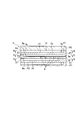
- FIG. 3 is a cross-sectional view taken along line AA of the heat exchange element of FIG. 2.
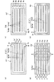
- 4A and 4B are diagrams for explaining a configuration of a flow path in the heat exchange element, in which FIG. 4A is a cross-sectional view taken along line BB of the heat exchange element of FIG. 3, FIG. 4C is a cross section taken along the line DD.
- Sectional drawing which shows other embodiment of the heat exchange body which comprises a reactor.
- 6A is a cross-sectional view taken along line VV of FIG. 5, FIG.
- FIG. 6B is a cross-sectional view taken along line WW
- FIG. 6C is a cross-sectional view taken along line YY
- FIG. ) Is a ZZ line cross section.
- the side view which shows one Embodiment of the reaction apparatus comprised using a heat exchanger.
- a heat exchange type reaction apparatus is a reaction apparatus having a heat exchange channel that circulates a heat medium fluid channel and a reaction channel that circulates a reaction fluid containing a reactant, and a heat medium.
- the reaction fluid is heated or cooled by using heat exchange between the fluid and the reaction fluid to advance the thermal reaction of the reactants.
- the reactants that is, the reaction raw materials or substances involved in the chemical reaction
- steam first reactant
- hydrocarbon compound second reaction
- the water vapor functions as an oxidizing agent.
- methane and water vapor react according to a water vapor reforming reaction represented by the following formula (1).
- a reaction represented by the following formula (2) proceeds. These reactions are endothermic reactions, and the reactions proceed by heating with a heat transfer fluid.
- the stoichiometric ratio of steam and methane in the steam reforming reaction is 1/1, and in principle, the steam and hydrocarbon are contained in a ratio of 1: 1.
- the reaction proceeds well by supplying the mixed gas to the reaction apparatus and heating.
- carbon is deposited as a by-product (coking), the surface of the reaction catalyst is covered and the catalyst becomes difficult to act, and the activity tends to decrease or deteriorate. For this reason, since the reaction efficiency is lowered or the catalyst needs to be replaced, the cost required for the catalyst and the cost required for performance adjustment and maintenance of the reaction apparatus become problems.
- the reaction is performed at an S / C ratio of about 2.5 to 3, and when LPG or naphtha containing a component having a large number of carbons is used.
- the steam reforming is performed by reacting at a higher S / C ratio than in the case of natural gas.
- the above-mentioned problems can be solved by devising the supply form of raw materials. Specifically, the source gas is divided into a plurality of parts, only a part is mixed with water vapor and reacted with water vapor from the beginning, and the remainder is replenished during the reaction.
- a reaction system having reaction conditions in which the S / C ratio is equal to or higher than the stoichiometric ratio can be configured. That is, in the present disclosure, as an effective technique for improving energy consumption and reaction efficiency, the second reaction is performed when the first reactant (for example, water vapor) and the second reactant (for example, hydrocarbon) are reacted. It is proposed to configure the reaction system (reaction apparatus, reaction system) so that the body is divided into a plurality of parts and the second reactant is sequentially supplied to the first reactant.
- the reaction system reaction apparatus, reaction system
- methane is divided into an initial portion and a replenishment portion, and a mixed gas of methane and water vapor for the initial portion is supplied to the reaction channel equipped with the reforming catalyst, and the replenishment portion is provided in the middle of the reaction channel.
- the above reforming reaction is an equilibrium reaction, and in an actual reaction system, a plurality of reactions can proceed in parallel.
- only the steam reforming reaction proceeds completely in the mixed gas. Assume that Since the reaction rate of the steam reforming reaction using a catalyst is very fast, it is assumed that the methane contained in the mixed gas is consumed before reaching the middle of the reaction channel, Methane becomes supplementary methane.
- the equivalent ratio (that is, the S / C ratio with respect to the total amount of methane) of the amount of water vapor supplied as a mixed gas to the total amount of methane (the sum of the initial amount and the replenishment amount) is N, and the replenishment of the total amount of methane
- the ratio of minutes is ⁇ (0 ⁇ ⁇ 1)
- N 1, the S / C ratio exceeds 1 in the period from the initial reaction to the middle. That is, a reaction with an S / C ratio exceeding 1 is possible using a stoichiometric amount of water vapor.
- the ratio of the amount of water vapor supplied as a mixed gas to the total amount of methane (total of the initial amount and the supplementary amount) (that is, S in the total amount of methane) / C ratio) is N
- the ratio of the first replenishment of the total amount of methane is ⁇
- the ratio of the second replenishment is ⁇ (0 ⁇ , ⁇ ⁇ 1, 0 ⁇ + ⁇ ⁇ 1).
- the divided supply is performed such that the replenishment ratio is ⁇ e, the supply amount of water vapor can be reduced while suppressing the precipitation of carbon.
- the value of N can be made closer to 1.
- the preferable value of the ratio to be divided as the supplement is obtained by a simplified approximation calculation.
- a split supply suitable for practical use can be obtained.
- the conditions can be determined more accurately. For example, in an example in which the change in the reactant concentration when the steam reforming reaction of methane is performed under the conditions of temperature: 800 ° C.
- carbon deposition is likely to occur due to the progress of the decomposition reaction of methane when the ratio of generated hydrogen to methane is small.
- the split supply of methane acts so as to increase the ratio of hydrogen to methane, and in this respect as well, the split supply of methane is advantageous for suppressing carbon deposition.
- a heat exchange type reaction apparatus capable of performing the steam reforming reaction by reducing the supply amount of steam so as to approach the stoichiometric ratio while suppressing the deposition of carbon on the surface of the reaction catalyst, and A reaction system can be provided.
- the amount of the first reactant supplied can be made close to the stoichiometric amount by dividing the portion as a replenishment portion and supplying the portion with a suitable division ratio.
- the execution of the thermal reaction by the divided supply of the reactants as described above can be performed by a reaction system using a general heat exchange type reaction apparatus.
- the reaction system is configured in such a manner that a plurality of reaction apparatuses are connected in series and the reactants are replenished between one reaction apparatus and the subsequent reaction apparatus. Reactants can be supplied.
- FIG. 1 shows an embodiment of a reaction system configured using a general heat exchange type reaction apparatus, in which water vapor is used as a first reactant M1 and hydrocarbon is supplied as a second reactant M2 to the reaction system. To do.
- the reaction system R in FIG. 1 has a first mixing section A1, a first reaction section B1, a second mixing section A2, and a second reaction section B2, which are sequentially connected in series by lines L1, L2, and L3. .
- the first mixing unit A1 and the second mixing unit A2 are devices for preparing a mixed fluid containing the first reactant and the second reactant. Each of these is only required to be able to prepare a mixed fluid by homogeneously mixing fluids, and is a gas used in preparing a mixed gas by mixing steam and hydrocarbons in a general reforming operation.
- a mixer is preferred.
- the present invention is not limited to this, and a mechanism having a flow control function equivalent to that of a mixer using a flow rate adjusting valve or a switching valve may be used.
- the first reaction part B1 and the second reaction part B2 are configured by using a reaction device that heats the prepared mixed fluid to advance a thermal reaction, and converts the mixed gas prepared from water vapor and hydrocarbons into hydrocarbons. By heating to the reforming temperature, it functions as a reformer that advances the reforming reaction of hydrocarbons.
- a heat exchange type reaction apparatus is preferably used as the reaction apparatus constituting the first reaction part B1 and the second reaction part B2.
- the heat exchange type reaction apparatus has a heat exchange body having a reaction flow path and a heat medium flow path inside, and heats the supplied mixed gas by heat exchange with the heat medium fluid. What is necessary is just to select suitably the reaction apparatus applied to 1st reaction part B1 and 2nd reaction part B2 from the reactor of the various forms generally utilized for reforming reaction.
- the reforming reaction is promoted by arranging the reforming catalyst in the reaction channel. From the viewpoint of ease of handling and the like, it is preferable to prepare the catalyst body by supporting the catalyst on the structure, and the catalyst body can be easily mounted in the reaction channel by loading it into the reaction channel.
- a heat transfer member made of a heat conductive material is installed in the heat medium flow path, so that heat transfer from the heat medium fluid to the heat exchanger is promoted, and a corrugated heat transfer A member is preferably used.
- an active metal such as Ni (nickel), Co (cobalt), Fe (iron), Pt (platinum), Ru (ruthenium), Rh (rhodium), Pd (palladium) is used as a catalyst component.
- the catalyst which has is mentioned. As long as it is effective for one type or for promoting the reaction, a plurality of types of catalysts may be used in combination, and may be appropriately selected from the above-described catalysts. When such a catalyst is supported on a structural material to prepare a catalyst body, it is easy to handle.
- the structural material that supports the catalyst is selected from available heat-resistant metals and ceramics that can be molded and can support the catalyst.
- a catalyst body is prepared by forming a thin plate-like structural material into a corrugated shape, it is preferable from the viewpoint of contact efficiency with a fluid.
- a catalyst body having a shape such as a pellet, tablet, or honeycomb is also preferable.
- heat-resistant metals include Fe (iron), Cr (chromium), Al (aluminum), Y (yttrium), Co (cobalt), Ni (nickel), Mg (magnesium), Ti (titanium), and Mo (molybdenum). ), W (tungsten), Nb (niobium), Ta (tantalum) and the like, and there are heat-resistant alloys mainly composed of one or more kinds of metals.
- a catalyst body by molding a thin plate-like structural material made of a heat-resistant alloy such as Fecralloy (registered trademark).
- a commercially available corrugated plate may be obtained and used.
- the catalyst loading method can be carried out using existing techniques, and an appropriate method may be appropriately selected from known methods according to the catalyst to be used. Specifically, there are a method of directly supporting on a structural material by surface modification or the like, and a method of indirectly supporting using a carrier. Practically, it is easy to load a catalyst using a carrier.
- the support is appropriately selected from materials that do not hinder the progress of the reaction carried out in the reaction apparatus and have durability and that can favorably support the catalyst to be used.
- Ceramics include metal oxides such as Al 2 O 3 (alumina), TiO 2 (titania), ZrO 2 (zirconia), CeO 2 (ceria), SiO 2 (silica), and the like.
- the species can be selected and used as a carrier.
- the supporting method using the carrier can be appropriately selected from known methods. For example, a method of forming a mixture layer of the catalyst and the carrier on the surface of the formed structural material, surface modification after forming the carrier layer, etc. And a method of supporting a catalyst.
- the supply line L4 of the first reactant M1 (water vapor) is connected to the first mixing part A1
- the supply line of the second reactant M2 (hydrocarbon) is branched to supply lines L5 and L6.
- a distributor D capable of adjusting the distribution ratio of the second reactant M2 supplied to the first mixing section A1 and the second mixing section A2 is installed at a branch portion of the supply lines L5 and L6.
- a line L7 for supplying a heating medium fluid H for heating is connected to the first reaction part B1 and the second reaction part B2.
- the heat transfer fluid H a fluid substance that does not corrode the constituent materials of the reaction apparatus can be suitably used.
- a liquid substance such as water or oil, or a gaseous substance such as combustion gas can be used.
- the configuration using a gaseous substance as the heat transfer fluid is easier to handle than the case of using a liquid medium.
- a mixed fluid that is, a mixed gas in which hydrocarbon gas is added to water vapor.
- This mixed gas is supplied as a reaction fluid to the first reaction section B1, heated by heat exchange with the heat transfer fluid H, and the reforming reaction proceeds.
- the reforming reaction proceeds by the catalyst in the reaction channel. Promoted.
- the reaction fluid (primary reformed gas) discharged from the first reaction section B1 contains hydrogen and carbon monoxide generated by the reforming reaction, and the hydrocarbons are consumed and the equivalent amount of the reacted hydrocarbons. Of water vapor is consumed.
- reaction fluid primary reformed gas
- the reaction fluid is supplied to the second mixing unit A2 and the remaining part of the second reactant M2 is replenished, then supplied to the second reaction unit B2, and similarly heated by the heat transfer fluid H.
- the reforming reaction proceeds.
- the hydrogen concentration of the reaction fluid (final reformed gas G) discharged from the second reaction part B2 is further increased. Get higher.
- an intermittent reaction channel composed of a first stage and a second stage is formed by the two heat exchangers of the reactor constituting the first reaction part B1 and the second reaction part B2. Then, water vapor flows through the first and second reaction channels as the first reactant. A part of the hydrocarbon, which is the second reactant, flows through the first stage reaction channel together with water vapor, and the remaining part is in the middle of the reaction channel (that is, the second mixing between the first stage and the second stage). In part A2), the reaction fluid is replenished. Accordingly, the second mixing section A2 to which the supply line of the second reactant M2 is connected forms a supply path for supplying the second reactant in the middle of the reaction channel. Thus, by supplying the mixing unit and the reaction unit repeatedly in series, the divided supply of the second reactant can be performed, and the supply division number is changed by changing the number of repetitions of the mixing unit and the reaction unit. it can.
- the progress of the hydrocarbon steam reforming reaction depends on the gas pressure and the reaction temperature, and varies depending on the type of catalyst, but generally proceeds at about 500 ° C. or higher.
- carbon deposition also occurs in a high temperature region, and remarkably easily occurs in a region of about 650 ° C. or higher. Therefore, in general, in steam reforming of natural gas, the reaction is allowed to proceed by supplying steam so that the S / C ratio is about 2 to 3.5. It is set to be about ⁇ 950 ° C.
- the heating temperature can be appropriately set so as to achieve a suitable progress according to the pressure of the gas supplied as a raw material (generally about 1 to 50 bar). Also in the reaction system R of FIG.
- the heating temperatures in the first reaction part B1 and the second reaction part B2 are described above in consideration of the optimum temperature in the catalyst used.
- the temperature range may be set as appropriate.
- the S / C ratio is preferably 1.2 or more at a temperature of 600 ° C. and 1.5 or more at 900 ° C.
- a higher S / C ratio is applied than in the case of natural gas.
- the second reactant M2 has a division ratio ⁇ (a ratio supplied to the second mixing portion A2) of the hydrocarbon replenishment of about 0.4 ( ⁇ e).
- the S / C ratio in the reaction channel is increased.
- the minimum value of is in the range of 2.5-3. Accordingly, the S / C ratio in the reaction fluid flowing through the reaction channel is always a value that is greater than or equal to this range.
- the ratio ⁇ e of replenishment such that this value becomes a suitable S / C ratio and the ratio N of the flow rate of water vapor to the total supply flow rate of the second reactant M2 are determined, these are used as reference values for the conditions of split supply You can proceed with the settings.
- the advantage of the split supply of reactants in the reaction system R is to set different heating temperatures in the first reaction section B1 and the second reaction section B2 or use different types of catalysts. Is also realized.
- the replenishment ratio ⁇ e and the second reactant M2 A ratio N of the flow rate of water vapor to the total supply flow rate may be determined.
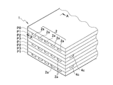
- FIGS. 2 to 4 show a main part of the heat exchange type reaction apparatus, that is, the heat exchange body 1
- FIG. 2 is a perspective view of a part of the heat exchange body 1
- FIG. 3 is a heat exchange body in FIG.
- FIG. 4 is a cross-sectional view for explaining each member constituting the heat exchange element 1.
- the heat exchanger 1 includes a heat medium flow path 2 through which the heat medium fluid H circulates, a reaction flow path 3 through which the reaction fluid F circulates, and a supply path 4 for replenishing the reactants in the middle of the reaction flow path. Have inside.
- the heat medium passage 2, the reaction passage 3, and the replenishment passage 4 are each branched into a plurality of parallel branch passages 2a, 3a, 4a. .
- the heat exchanger 1 is configured in a multistage structure in which the heat medium flow path 2, the reaction flow path 3, and the replenishment path 4 are sequentially repeated in the vertical direction. In the heat exchanger 1 of FIGS.
- the heat exchanger 1 has a plurality of through holes 8 that connect the branch flow path 3 a of the reaction flow path 3 and the branch flow path 4 a of the supply path 4. The flowing reactant is supplied to the branch channel 4 a of the reaction channel 3 through the through hole 8.
- a catalyst body Ct is attached to the branch channel 3 a of the reaction channel 3.
- the catalyst body Ct has a corrugated plate shape that is curved in a wavy shape, a shape that bends in a jagged manner, or a shape that is similar to these. Well, it is inserted into the branch flow path 3a and fixed in a detachable manner.
- the catalyst body Ct is preferably a length corresponding to the branch flow path 3a of the reaction flow path 3, but is not limited thereto.
- FIG. 2 and 3 can be configured as an assembly using a flat plate in which a channel groove is formed on one side.
- a flat plate P1 in which the groove 5 for the heat medium flow path 2 is formed a flat plate P2 in which the groove 6 for the reaction flow path 3 is formed, and a flat plate P3 in which the groove 7 for the replenishment path 4 is formed.
- the heat exchanging body 1 is formed by stacking in order and assembling so as to cover the groove of the uppermost flat plate P1 with a flat plate P0 (lid body) having no groove.
- the flat plates P0 to P3 are manufactured using rectangular flat plate members made of a heat conductive material having heat resistance.
- Such a flat plate type heat exchange element 1 is easy to form a groove in accordance with a change in conditions concerning the divided supply of reactants, and a groove having an appropriate through hole is formed on a flat plate using a cutting tool.
- the assembled heat exchanger is provided with a replenishment path capable of dividing and supplying the reactants.
- FIG. 4 is a cross-sectional view of the heat exchanger 1 for explaining the form of grooves in each flat plate constituting the heat exchanger 1.
- 4A is a cross-sectional view taken along the line BB in FIG. 3 of the flat plate P1 on which the groove 5 for the heat medium flow path 2 is formed
- FIG. 4B is a view where the groove 6 for the reaction flow path 3 is formed.
- 3 is a cross-sectional view taken along the line CC of FIG. 3 of the flat plate P2
- FIG. 4C is a cross-sectional view taken along the line DD of FIG. 3 of the flat plate P3 in which the groove 7 for the supply path 4 is formed.
- FIG. 4A is a cross-sectional view taken along the line BB in FIG. 3 of the flat plate P1 on which the groove 5 for the heat medium flow path 2 is formed
- FIG. 4B is a view where the groove 6 for the reaction flow path 3 is formed.
- 3 is a cross-sectional view taken along the line CC
- the groove 5 formed in the flat plate P ⁇ b> 1 includes a groove 5 a for the branch channel 2 a of the heat medium channel 2 and a groove 5 b for the combined channel 2 b in which the branch channels are integrated.
- the groove 6 formed in the flat plate P2 includes a groove 6a for the branch channel 3a of the reaction channel 3 and a groove 6b for the combined channel 3b in which the branch channels are integrated.
- the groove 7 formed in the flat plate P3 includes a groove 7a for the branch channel 4a of the supply path 4 and a groove 7b for the combined channel 4b in which the branch channels are integrated.
- FIG. 4B the description of the catalyst body Ct shown in FIG. 3 is omitted in order to clearly show the through holes formed in the flat plate P2.
- the flat plate P1 has a base portion 11, a side wall portion 13, an intermediate wall portion 15, and an end wall portion 17.
- the groove 5 of the flat plate P1 constitutes the heat medium flow path 2.
- the base part 11 defines the bottom surface of the heat medium flow path 2
- the side wall part 13, the intermediate wall part 15, and the end wall part 17 stand on the base part 11 and define the side surface of the heat medium flow path 2.
- the lower surface of the flat plate P0 (or flat plate P3) is the upper surface of the heat medium flow path 2.
- the side wall part 13 and the end wall part 17 are provided along the three ends of the flat plate P1, and the intermediate wall part 15 is formed between the side wall parts 13 on both sides in parallel and at equal intervals.
- the grooves 5a are parallel to each other at equal intervals through the inter-wall portion 15, and one end thereof is connected perpendicularly to the groove 5b, and both ends of the groove 5b pass through the side wall portion 13 and are opened to the outside.
- the inlet 2c of the heat medium flow path 2 is formed.
- the other end of the groove 5a is opened to the outside, and forms a discharge port 2d of the heat medium flow path 2 in the stacked state.
- the heat medium flow path 2 having a plurality of (five in this embodiment) branch flow paths 2a and the combined flow paths 2b whose rectangular cross section with respect to the flow direction is rectangular is formed in the groove 5a. , 5b.
- the heat transfer fluid H is introduced from the two inlets 2c, the heat transfer fluid H sequentially flows through the combined flow path 2b and the branch flow path 2a and flows out from the discharge port 2d.
- heat transfer member a corrugated plate generally used as a heat radiating fin or a heat sink can be used.
- heat conductive material constituting the heat transfer member metals such as aluminum, copper, stainless steel, iron-based plated steel, naval copper, and aluminum brass are suitable.
- the flat plate P2 in which the groove 6 for the reaction flow path 3 is formed has a configuration similar to that of the flat plate P1, but differs in that it has a through hole 8 for receiving the supply of the reactant from the supply path 4. That is, as shown in FIG. 4B, the flat plate P2 has a base portion 21, a side wall portion 23, an inter-wall portion 25, and an end wall portion 27, and the flat plate P2 is formed by stacking the flat plate P1 on the flat plate P2.
- the groove 6 constitutes the reaction channel 3.
- the base portion 21 defines the bottom surface of the reaction channel 3, and the side wall portion 23, the intermediate wall portion 25, and the end wall portion 27 are erected on the base portion 21 to define the side surface of the reaction channel 3, and
- the lower surface is the upper surface of the reaction channel 3.
- the side wall part 23 and the end wall part 27 are provided along the three ends of the flat plate P2, and the inter wall part 25 is formed between the side wall parts 23 on both sides in parallel and at equal intervals.
- the grooves 6a are parallel to each other at equal intervals through the inter-wall portion 25, and one end thereof is connected perpendicularly to the groove 6b, and one end of the groove 6b passes through the side wall portion 23 and is opened to the outside.
- the inlet 3c of the reaction channel 3 is formed.
- the other ends of the grooves 6a are each opened to the outside to form an outlet 3d of the reaction channel 3 in a stacked state.
- a reaction channel having a plurality of (five in this embodiment) branch channels 3a and a combined channel 3b whose rectangular cross section with respect to the flow direction is rectangular. 3 is formed by the grooves 6a and 6b.
- a catalyst body Ct is installed in the branch channel 3a of the reaction channel 3 (not shown in FIG. 4B), and when the reaction fluid F is introduced from the introduction port 3c, the reaction fluid F is separated from the combined channel 3b and the branch channel. 3a is circulated sequentially, and after coming into contact with the catalyst body Ct, it flows out from the plurality of discharge ports 3d.
- the catalyst body Ct can be attached to the branch flow path 3a of the reaction flow path 3 either before or after assembly of the heat exchange element 1, and after assembly, it can be mounted by being inserted from the discharge port 3d.
- the introduction port 3c of the reaction channel 3 is located on the side opposite to the introduction port 2c of the heat medium channel 2, and in the assembled heat exchanger 1, the heat medium fluid H and the reaction fluid F circulate in the opposite direction. It is configured as a counterflow type. However, this can be changed to a parallel flow type by reversing the supply / discharge of the heat transfer fluid H.
- the flat plate P3 in which the groove 7 for the supply path 4 is formed also has a configuration similar to that of the flat plate P1, but the groove 7 is formed so that the supply path 4 has only the introduction port 4c. That is, as shown in FIG. 4C, the flat plate P3 has a base portion 31, a side wall portion 33, an inter-wall portion 35, and an end wall portion 37, and the flat plate P3 is laminated on the flat plate P3, thereby forming the flat plate P3.
- the groove 7 constitutes the supply path 4.
- the base 31 defines the bottom surface of the supply path 4, and the side wall portion 33, the intermediate wall portion 35, and the end wall portion 37 are erected on the base portion 31 to define the side surface of the supply path 4, and the lower surface of the flat plate P ⁇ b> 2 is This is the upper surface of the supply path 4.
- the side wall part 33 and the end wall part 37 are provided along the four ends of the flat plate P3, and the inter wall part 35 is formed between the side wall parts 33 on both sides in parallel and at equal intervals.
- the grooves 7a are parallel to each other at equal intervals through the inter-wall portion 35, and one end thereof is connected perpendicularly to the groove 7b, and one end of the groove 7b passes through the side wall portion 33 and is opened to the outside.
- the inlet 4c of the supply path 4 is formed.
- the base 21 of the flat plate P2 is provided with a plurality of through holes 8 in the middle of each of the grooves 6a, and the lower side of the flat plate P2 and the groove 6a define the through holes 8. Communicate through. Accordingly, the branch flow path 4a of the supply path 4 of the flat plate P3 in the stacked state is connected to the branch flow path 3a of the reaction flow path 3 of the flat plate P2 through the through hole 8.
- the second reactant M2 when the second reactant M2 is introduced from the inlet 4c, the second reactant M2 sequentially flows through the combined channel 4b and the branch channel 4a and passes through the through hole 8.
- a replenishment path 4 having a plurality (five in this embodiment) of branch flow paths 4a and combined flow paths 4b having a rectangular cross section with respect to the flow direction is formed by grooves 7a and 7b. Since the replenishment path 4 only needs to be replenished through the through hole 8 of the flat plate P ⁇ b> 2, the branch flow path 4 a of the replenishment path 4 is formed to have a length that reaches the most downstream through hole 8 of the reaction flow path 3. .
- the divided supply of the second reactant M2 can be appropriately adjusted by setting the through-hole 8 provided in the base 21 in the middle of the groove 6a of the flat plate P2. That is, if the number of through-holes 8 provided for one branch flow path (that is, the number of supply stages) is 1, the supply is divided into two parts, and if the number of through-holes 8 is n, the supply is divided into (n + 1) parts. Further, the supply timing of the second reactant M2 is determined by the position of the through hole 8.
- the flow rate of the second reactant M2 flowing through the through hole 8 can be regulated to some extent by the opening area of the through hole 8, when a plurality of through holes 8 are provided in one branch flow path, The distribution ratio of the second reactant M2 dividedly supplied to the reaction channel can be adjusted to some extent by the opening area of each through hole 8.
- the fluid including the first reactant M1 and the second reactant M2, that is, the mixed gas of water vapor and hydrocarbon is supplied as the reaction fluid F to the reaction channel 3 of the heat exchanger 1.
- the heat exchanger 1 shown in FIGS. 2 to 4 can also be configured to include the function of the first mixing part A1 of the reaction system R of FIG. That is, the through-hole 8 is provided at a branch position where the reaction flow path 3 branches from the combined flow path 3b to the branch flow path 3a so that the second reactant M2 is mixed with the reaction fluid F at the upstream end of each branch flow path 3a.
- a flat plate P2 is formed.
- a fluid containing only the first reactant M1 (water vapor) is supplied as the reaction fluid F to the inlet 3c of the reaction channel 3, and the second reactant M2 is supplied to the inlet 4c of the supply channel 4.
- a mixed gas of the first reactant M1 and a part of the second reactant M2 is prepared.
- the reaction of the mixed gas proceeds while flowing through the branch flow path 3a, and the supplementary second reactant M2 is further supplied in the middle of the branch flow path 3a.
- the heat exchange element 1 of FIGS. 2 to 4 can be transformed into a laminated structure in which the arrangement order of the flat plates P1 to P3 in the vertical direction is reversed.
- the through hole 8 for enabling the replenishment of the second reactant is not in the flat plate P2 having the groove 6 for the reaction flow path 3 but in the base 31 of the flat plate P3 having the groove 7 for the replenishment path 4. It is formed.
- the heat exchanger 1 ′ shown in FIG. 5 has a flat plate P1 ′ formed with a groove for a heat medium flow path, a flat plate P2 ′ formed with a groove for a forward path of the reaction flow path, and a groove for a supply path.
- the flat plate P3 ′ and the flat plate P4 on which the return channel of the reaction flow path is formed are sequentially overlapped, and the flat plate P0 (lid body) having no groove is assembled so as to cover the groove of the uppermost flat plate P1.
- the reaction channel has a forward path of the flat plate P2 ′ and a return path of the flat plate P4, and the forward path and the return path are connected by through holes 9a and 9b formed in the base portion of the flat plate P2 ′ and the end wall portion of the flat plate P3 ′.
- the A catalyst body Ct is attached to the forward path 3e of the reaction flow path 3 '.
- FIG. 6 is a cross-sectional view of the heat exchange element 1 ′ for explaining the form of grooves in each flat plate constituting the heat exchange element 1 ′ of FIG. 5.
- 6A is a cross-sectional view taken along the line VV of the flat plate P1 ′ in FIG. 5
- FIG. 6B is a cross-sectional view taken along the line WW of the flat plate P2 ′ in FIG. 5
- FIG. 5 shows a YY line cross section of the flat plate P3 ′ in FIG. 5
- FIG. 6D shows a ZZ line cross section of the flat plate P4 in FIG.
- the description of the catalyst body Ct shown in FIG. 5 is omitted in order to clearly show the through-hole formed in the flat plate P2 '.
- the groove 5 ′ formed in the flat plate P1 ′ includes the groove 5e and the groove 5f constituting the introduction path 2e and the outlet path 2f of the heat medium flow path 2 ′.
- H is supplied to the introduction path 2e from the introduction port 2c formed in the side wall portion of the flat plate P1, and is discharged from the discharge port 2d ′ which is the open end of the lead-out path 2f.
- the groove 6 ′ constituting the reaction flow path 3 ′ is formed in the groove 6e for the forward path 3e formed in the flat plate P2 ′ and in the flat plate P4. Grooves 6f and 6g for the return paths 3f and 3g.
- a through hole 9a that penetrates the base portion of the flat plate P2 ' is formed at the end position of the groove 6e, and further, a through hole 9b that penetrates the end wall portion of the flat plate P3' It is formed at a position corresponding to the through hole 9a of P2 ′ (see FIG. 6C).
- the flat plate P3 ' has substantially the same configuration as the flat plate P3 of FIG. 4C except that it has a through hole 9b.
- a heat transfer member that promotes heat transfer from the heat transfer fluid can be arranged in the introduction path 2e and the discharge path 2f of the heat transfer path 2 'as necessary. In this case, the heat transfer member is mounted in the groove of the flat plate P1 'before assembling the heat exchange element 1'.
- the heat medium fluid H when the heat medium fluid H is supplied from the inlets 2c on both sides of the flat plate P1 ′, the heat medium fluid H sequentially flows through the inlet path 2e and the outlet path 2f and is discharged to the outlet. Outflow from 2d '.
- the reaction fluid F including the first reactant M1 (and the second reactant M2) is introduced from the introduction port 3c ′ on one end face of the flat plate P2 ′ to the parallel forward path 3e, and the catalyst body Ct (FIG. 6B).
- the return path 3g after flowing through the return path 3f in parallel with the flat plate P4 from the downstream end of the forward path 3e through the through hole 9a and the through hole 9b of the flat plate P3 ′.
- the second reactant M2 for replenishment is supplied from the inlet 4c on one side of the flat plate P3 ′ to the combined flow path 4b, and flows through the branch flow path 4a through the plurality of through holes 8 of the flat plate P2 ′. It is intermittently supplied to the forward path 3e of the reaction flow path 3 ′.
- the second reactant M2 hydrocarbon
- the second reactant M2 hydrocarbon
- the second reactant M2 is heated by the amount of heat of the reaction fluid (final reformed gas G) flowing through the return path 3f while flowing through the branch flow path 4a.
- a catalyst body can be provided as necessary in at least a part of the return path 3f of the reaction flow path 3 ', particularly in a part on the upstream side.
- the catalyst body is attached to the return path 3f before assembly.
- the catalyst body Ct can be attached to the forward path 3e of the reaction flow path 3 'either before or after assembly of the heat exchanger 1'.
- the heat exchange element 1 ′ is the same as the heat exchange element 1 except for the points described above, and the description relating to the heat exchange element 1 can be referred to, so detailed description thereof is omitted.
- the heat exchanger is described as a laminated body in which flat plate heat transfer bodies are laminated.
- the heat exchanger need not be such a laminate.
- vertical to a flow direction is a rectangle is demonstrated, the cross section of a flow path may be other shapes, such as a column shape and elliptical column shape.
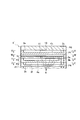
- FIG. 7 shows an embodiment of a reaction apparatus configured using a heat exchanger.
- the heat exchange element 1 ′′ of the reaction apparatus 10 in FIG. 7 is configured with three flat plates P1 to P3 as one stacked unit, similar to the heat exchange element 1 in FIGS. 2 to 4. That is, the flat plates P1 to P3. Are horizontally stacked and sequentially stacked in the vertical direction, and the flat plate P0 is placed on the uppermost part and assembled into a rectangular parallelepiped stacked body.
- the heat exchanger 1 ′′ in FIG. 2 has substantially the same structure as the heat exchange element 1 of FIG.
- Both ends of the laminated body are fitted into a rectangular annular fixing member 40, and the members laminated by the fixing member 40 that circulates around the outer periphery are closely fixed to maintain the laminated structure. If the members are fixed together using a joining method such as TIG (Tungsten Inert Gas) welding or diffusion joining during the assembly of the laminate, deterioration of heat transfer due to poor contact between the members is prevented.
- the heat exchanging body 1 ′′ can be configured by using at least one laminated unit of the flat plates P1 to P3. However, the heat exchange performance is better when the number of laminated units is larger.
- the number of units is plural (four), the number of flat plates P1 is one more than the number of flat plates P2 and P3, and the flat plates P1 are located at the uppermost and lowermost positions.
- Covering the periphery of the heat exchanger 1 "with a housing or heat insulating material so as to suppress heat dissipation from the heat is preferable in terms of suppressing heat loss. Covering a plurality of heat exchangers 1" with one housing,
- the reaction apparatus 10 may be configured to have a plurality of heat exchangers 1 ′′.
- heat-resistant metals such as iron alloys and nickel alloys.
- iron alloys such as stainless steel, Inconel 625 (registered trademark). , Inconel 617 (registered trademark), Haynes 230 (registered trademark), and other heat-resistant alloys such as nickel alloys, etc.
- These heat conductive materials can be used as a reaction flow in a reaction flow path or a heat transfer fluid. It is preferable because it has durability (corrosion resistance) to gas, but is not limited to these, and may be iron-based plated steel, metal coated with a heat-resistant resin such as fluororesin, carbon graphite, or the like.
- the fixing member 40 for fixing the body is made of a material having heat resistance and strength, and is preferably a material having low thermal conductivity in order to suppress heat loss due to heat dissipation. If the fixing member 40 is formed by the same material as the heat exchange element 1 "it is preferably coated with a heat insulating material. If the housing is configured to be connected to the fixing members 40 on both sides, it is preferable in terms of suppressing heat dissipation.
- the heat exchange element 1 ′′ is supported by a heat-insulating support column 41 having strength.
- the introduction port 2c of the heat medium passage and the introduction port 4c of the supply passage are opposite to each other. Open so that it is located at the end.
- the introduction port of the heat medium flow channel and the introduction port of the reaction flow channel are located at opposite end portions. Open to position.
- a vertically long and hollow introduction member 43 having a longitudinal opening is attached to the side surface of the heat exchanger 1 '' so as to cover the introduction port 2c of the heat medium flow path, and connects the introduction port 2c in the vertical direction.
- a fluid supply passage is formed, and an introduction pipe 45 is connected to the center of the introduction member 43.
- the opposite side surface is also vertically long so as to cover the introduction port of the heat medium passage.
- a supply channel for the heat transfer fluid is formed by attaching a hollow introduction member, and similarly, a vertically long and hollow introduction member 47 having an opening in the longitudinal direction exchanges heat so as to cover the introduction port 4c of the supply passage.
- a supply path for the second reactant is formed which is attached to the side surface of the body 1 ′′ and connects the inlet 4c in the vertical direction.
- a reaction channel supply passage is formed on the opposite side surface by attaching a vertically long and hollow introduction member so as to cover the introduction port of the reaction channel.
- An introduction pipe 49 is connected to the center of the introduction member 47.
- the reaction fluid including a part of the first reactant and the second reactant is mixed. It can be prepared by a vessel and supplied to the reaction channel of the reaction apparatus 10.
- the line for supplying the second reactant is branched through a distributor and connected to the mixer and the reactor 10.
- the reaction fluid containing the first reactant and a part of the second reactant is changed to the reaction apparatus 10. It is also possible to prepare in the inside. In that case, a part of the second reactant M2 flows into the reaction fluid F at the upstream end of the branch channel of the reaction channel to prepare a mixed gas. Accordingly, the mixer can be omitted, and the fluid containing only the first reactant M1 (water vapor) can be directly supplied to the reaction flow path of the reaction apparatus 10 as the reaction fluid F.
- the heat exchanger element 1 ′′ has a concavely curved end plate 51 attached to the side surface on the side having the discharge port of the heat medium passage so as to be detachable or openable.
- the end plate 51 covers the side surface of the heat exchange element 1 ′′ so that a space is formed in the center.
- An outlet pipe 53 is provided in the center of the end plate 51. Therefore, when the heat transfer fluid is supplied from the introduction tube 45, the heat transfer fluid Flows from the introduction member 43 to the introduction port 2c and flows through the heat medium passage, and the heat medium fluid released from the heat exchanger 1 "is led out through the space between the end plate 51 and the heat exchanger 1".
- the heat exchanging body 1 ′′ is attached to the side surface of the reaction flow path on the side having the discharge port so that a concavely curved end plate 55 is detachably attached or opened and closed.
- the end plate 55 is located on the side of the heat exchanger 1 '' so that a space is formed between the end plate 1 "and the end plate 55.
- a lead-out tube 57 is provided at the center of the end plate 55. Accordingly, the reaction fluid supplied from the introduction pipe flows into the reaction flow path in the heat exchange body 1 ′′ from the introduction member, and the reaction fluid discharged from the heat exchange body 1 ′′ is the end plate 55 and the heat exchange body 1 ′′.
- the second reactant for replenishment is supplied from the introduction pipe 49 through the introduction member 47 and the introduction port 4c to the replenishment path of the heat exchange body 1 ′′, and the heat exchange body. 1 ′′ is intermittently supplied to the reaction fluid flowing through the reaction flow path.
- the flow direction of the heat transfer fluid from the introduction pipe 45 to the outlet pipe 53 can be changed in the reverse direction. .
- the configuration of the reaction apparatus 10 can be applied to a so-called compact reactor having a large specific surface area per unit volume of the reaction channel.
- the configuration of the heat exchanger as described above can be applied to any of a liquid-liquid heat exchanger, a gas-gas heat exchanger, and a gas-liquid heat exchanger.
- the fluid can be handled in the reactor 10 regardless of whether it is a gas or a liquid. Therefore, an objective fluid can be synthesized by supplying an arbitrary fluid having a substance (reactant) such as a raw material involved in a chemical reaction as a reaction fluid to the reaction apparatus 10.
- the reaction fluid may contain a carrier that does not participate in the reaction.
- the carrier can be appropriately selected from substances that do not affect the progress of the reaction in consideration of the chemical reaction to be performed.
- a carrier that can be used in the gaseous reaction fluid an inert gas or a low-reactive gas is used.
- Gas carriers such as particulate matter (at the temperature in the reactor).
- a heat exchange type reaction device that uses a heat exchange with a heat transfer fluid to promote a thermal reaction with heat generation or endotherm, and a chemical reaction carried out at a reactant ratio different from the stoichiometric ratio
- Reactors capable of improving conditions and improving efficiency in chemical synthesis are provided, and in chemical synthesis such as steam reforming reactions, cost reduction by improving the durability and service life of the reaction catalyst, stable supply of target products and production costs This is useful for realizing reductions in energy consumption.
Landscapes
- Engineering & Computer Science (AREA)
- Thermal Sciences (AREA)
- Mechanical Engineering (AREA)
- General Engineering & Computer Science (AREA)
- Physics & Mathematics (AREA)
- Chemical & Material Sciences (AREA)
- Chemical Kinetics & Catalysis (AREA)
- Organic Chemistry (AREA)
- Hydrogen, Water And Hydrids (AREA)
- Catalysts (AREA)
- Physical Or Chemical Processes And Apparatus (AREA)
- Health & Medical Sciences (AREA)
- General Health & Medical Sciences (AREA)
- Combustion & Propulsion (AREA)
- Inorganic Chemistry (AREA)
Abstract
反応装置は、熱媒流体を流通させる熱媒流路と、第一反応体(及び第二反応体)を含有する反応流体を流通させる反応流路と、反応流路の途中に第二反応体を補給するための補給路とを内部に有する熱交換体を有する。反応流路内に反応流体における反応を促進する触媒体が設けられる。熱交換体は、補給路が反応流路の途中と連通する複数の孔を有する。第一反応体及び第二反応体として水蒸気及び炭化水素を用いて水蒸気改質が行われる。
Description
本開示は、反応体(反応原料)を含んだ流体である反応流体を、熱媒流体との熱交換を利用して加熱又は冷却することによって反応体の化学反応を進行させるための熱交換型の反応装置及び反応システムに関する。
熱交換型の反応装置は、反応体(反応原料)を含んだガス状又は液状の流体を加熱又は冷却して反応体の熱的反応(吸熱反応、発熱反応)を進行させる化学反応装置として知られている。このような反応装置では、反応流体を流通させる反応流路と熱媒流体を流通させる熱媒流路とが装置内に設けられ、反応流体及び熱媒流体が各々入口から供給されて出口から排出される迄の間に相互の熱交換が進行するように構成される。反応装置内に設けられる反応流路及び熱媒流路は、概して、熱交換を容易にするために、各々、複数の流路に分岐して伝熱面積が増加するように形成される。又、化学反応の進行は、触媒の使用によって促進されるので、反応流路内に触媒を設置すると、反応流路内での反応効率を向上させることが可能である。このような反応装置は、天然ガスや合成ガス、水素ガス等の製造/精製プラントにおいて、メタンの水蒸気改質反応やドライリフォーミング反応等の熱的反応を実施する装置として利用することができ、その重要性は、近年の水素製造技術への関心が高まるに伴って増しつつある。
化学反応における反応速度及び反応効率は、反応条件によって変化し得るので、化学反応を好適な反応効率で良好に進行させるためには、反応装置に供給される反応流体の組成(反応体濃度)や供給速度等を調整可能なように反応装置を構成することが好ましい。特開2012-246170号公報(下記特許文献1)には、燃焼空気の熱を利用して水蒸気改質を行う改質器に原料及び水を供給して水素を生成する水素生成装置及び燃料電池システムが開示され、改質器の温度が所定温度になるように改質器への水の供給量及び燃焼空気のうちの一方を制御することが記載される。このように、原料の供給を制御することによって、反応条件を好適化することができる。
他方、再公表特許WO2011/148604(下記特許文献2)にも、水蒸気改質によって水素を生成する改質器を備えた燃料電池システムが開示される。但し、この文献においては、原料及び水の供給を停止した後に、残留水によって改質触媒が劣化することを抑制するために原料ガスを改質器に供給するように原料ガスの供給を制御することが記載される。
水蒸気改質反応において使用する反応触媒に関する問題は、上述の反応停止後の劣化だけでなく、反応進行中に炭素が生じて触媒表面へ析出する点もある。炭素析出が生じると、触媒の被覆による反応体との接触阻害によって反応が困難になる。このため、反応効率が低下し、屡々、触媒の交換が必要となる。炭素析出は、水蒸気を化学量論量より過剰に供給することによって抑制することが可能である。しかし、水蒸気の供給によるエネルギー消費は大きく、供給量を可能な限り削減できることが望ましい。又、原料ガスの濃度が相対的に低くなるため、反応効率や生成物の回収効率の点においても不利になる。従って、炭素の析出を抑制すると共に水蒸気の供給量を削減可能な技術的改善が必要である。
好ましくない副生成物の生成は、水蒸気改質反応に限らず、様々な化学反応において屡々見られる。その対策は、反応の種類によって異なるにしても、化学量論比とは異なる比率で反応体が反応するように反応系に工夫を施すことは多い。従って、このような化学反応の進行において副生成物を抑制しつつ反応効率を高めるための技術的改善は重要であり、このような技術的改善が成された熱交換型の反応装置の提供は、工業生産において、水蒸気改質反応のみならず、様々な化学反応にとって非常に有用な手段となり、副生成物を抑制しつつ効率的に反応を進行させることが可能となる。
本開示は、このような課題を解決し、副生成物の生成を抑制可能な反応体の比率が化学量論比とは異なる反応において、反応体の供給を化学量論比に近づけつつ副生成物の抑制を実現し得る熱交換型の反応装置及び反応システムを提供することを目的としている。
上記課題を解決するために、本願発明者等は、熱交換型の反応装置の構成について鋭意研究を行い、反応体の供給を化学量論比に近づけつつ副生成物の生成を抑制することが可能な装置構成及びシステム構成を見出し、本開示の技術を成すに至った。
本開示の一態様によれば、反応装置は、熱媒流体と反応流体との熱交換を利用して前記反応流体において反応を進行させる反応装置であって、前記熱媒流体を流通させる熱媒流路と、第一反応体を含有する反応流体を流通させる反応流路と、前記反応流路の途中に第二反応体を補給するための補給路とを内部に有する熱交換体、及び、前記反応流路内に設けられて前記反応流体における反応を促進する触媒体を有することを要旨とする。
上記反応装置において、前記熱交換体は、前記補給路が前記反応流路の途中と連通する複数の孔を有するように形成され、前記第二反応体は、前記複数の孔を通じて断続的に前記反応流路の反応流体に補給されるように構成することができる。更に、第二反応体を一部と残部とに分割する分配器と、前記分配器によって分割される前記第二反応体の一部と第一反応体とを含有する混合物を生成する混合器とを有するように構成し、前記分配器は、前記第二反応体の残部を前記補給路へ供給し、前記混合器は、前記混合物を前記反応流体として前記反応流路に供給すると好都合である。前記第二反応体を分割する比率を調整可能な分配器を用いると好適である。上記反応装置を炭化水素の水蒸気改質に使用する場合、前記第一反応体は水蒸気を含み、前記第二反応体は炭化水素を含む。
又、本開示の一態様によれば、反応システムは、熱媒流体と反応流体との熱交換を利用して第一反応体と第二反応体との反応を進行させる反応システムであって、熱媒流体との熱交換を利用して、第一反応体と第二反応体の一部とを含有する反応流体において第一反応体と第二反応体との反応を進行させる第一反応部と、前記第一反応部から排出される反応流体に第二反応体の残部を補給する混合部と、熱媒流体との熱交換を利用して、前記混合部によって第二反応体の残部が補給された反応流体において第一反応体と第二反応体との反応を進行させる第二反応部とを有し、前記第一反応部及び第二反応部は、各々、第一反応体と第二反応体との反応を促進させる触媒体が内部に設けられた熱交換体を有することを要旨とする。
前記熱交換体は、前記熱媒流体を流通させる熱媒流路と、前記反応流体を流通させる反応流路とを内部に有し、前記触媒体は前記反応流路に設けられる。更に、第二反応体を一部と残部とに分割する分配器を有し、前記分配器によって分割される前記第二反応体の一部と第一反応体とを有する混合物が前記反応流体として前記第一反応部に供給され、前記分配器は、前記第二反応体の残部を前記混合部へ供給するように構成するとよい。
又、本開示の一態様によれば、上記反応装置又は反応システムを用いて遂行可能な反応方法は、熱媒流体と反応流体との熱交換を利用して前記反応流体において改質反応を進行させる反応方法であって、炭化水素を一部と残部とに分割する分割処理と、触媒の存在下で、炭化水素の一部及び酸化剤を含有する反応流体と熱媒流体とを熱交換させて炭化水素の改質反応を進行させる反応処理と、前記反応処理の途中の反応流体に炭化水素の残部を補給する補給処理とを有し、前記反応処理に供給される初期の反応流体における酸化剤量の炭化水素量に対する比率、及び、前記補給処理で炭化水素が補給された反応流体における酸化剤量の炭化水素量に対する比率が、前記改質反応に最適な比率になるように、炭化水素及び酸化剤の使用量が調整される。
本開示によれば、水蒸気改質反応等のような化学量論比とは異なる反応体比で実施されている熱的反応について、副生成物等を抑制しつつ反応体比を化学量論比に近づけることができ、条件改善及び効率化が可能な反応装置が提供されるので、熱的反応を利用した化学合成において、反応触媒の耐久性及び使用寿命の向上による費用の削減や、目的とする反応生成物の安定供給及び製造コストの削減に寄与することができる。
熱交換型の反応装置は、熱媒流体を流通させる熱媒流路と、反応体を含有する反応流体を流通させる反応流路とを内部に有する熱交換体を有する反応装置であり、熱媒流体と反応流体との熱交換を利用して反応流体を加熱又は冷却することによって反応体の熱的反応を進行させる。このような反応装置を用いて水蒸気改質を実施する場合、反応体(つまり、反応原料、又は、化学反応に関与する物質)は、水蒸気(第一反応体)及び炭化水素化合物(第二反応体)であり、水蒸気は酸化剤として機能し、例えば、メタンと水蒸気とは、下記式(1)のような水蒸気改質反応に従って反応する。又、酸化剤として二酸化炭素を用いて改質するドライリフォーミング反応においては、下記式(2)のような反応が進行する。これらの反応は吸熱反応であり、熱媒流体による加熱によって反応が進行する。
CH4 + H2O → 3H2 + CO ----式(1)
[炭化水素に一般化した場合: CnHm+nH2O→(n+m/2)H2+nCO]
CH4 + CO2 → 2H2 + 2CO ----式(2)
[炭化水素に一般化した場合: CnHm+nH2O→(n+m/2)H2+nCO]
CH4 + CO2 → 2H2 + 2CO ----式(2)
上記式(1)から解るように、水蒸気改質反応における水蒸気とメタンとの化学量論比は1/1であり、原理的には、水蒸気と炭化水素とを1対1の割合で含有する混合ガスを反応装置に供給して加熱することによって反応は良好に進行することになる。しかし、実際には、副生成物として炭素が析出し(コーキング)、反応触媒表面を被覆して触媒が作用し難くなり、又、活性低下や劣化を生じ易い。このため、反応効率が低下したり、触媒の交換が必要となるので、触媒に要する費用や反応装置の性能調整、メンテナンスに要する費用が問題となる。炭素が析出する反応としては、複数の反応が存在し、例えば、原料ガスである炭化水素の分解反応(下記式(a)参照)や、生成した一酸化炭素の不均化反応(下記式(b)参照)などが挙げられる。この他に、原料ガスに含まれる微量の不飽和炭化水素や芳香族成分に起因する反応などもある。
CH4 → C + 2H2 ----式(a)
2CO → C + CO2 ----式(b)
2CO → C + CO2 ----式(b)
炭素の析出は、水蒸気と炭化水素の炭素数との比率(S/C比:Steam to Carbon ratio)が小さいと生じ易くなり、又、炭素数が多い炭化水素を使用する場合にも炭素析出が生じ易くなる。他方、上記式(1)の水蒸気改質反応と同時に、一酸化炭素と水蒸気とから二酸化炭素及び水素が生成するシフト反応が触媒中で進行することが知られている。このようなことから、一般的に、反応装置に供給する原料ガスに対して予め過剰量の水蒸気を混合し、S/C比を大幅に増加させた状態で反応装置に供給して水蒸気改質反応が行われる。例えば、メタンが豊富な天然ガス等を原料として使用する場合には、2.5~3程度のS/C比で反応させ、炭素数が多い成分を含むLPGやナフサ等を使用する場合には、天然ガスの場合より高いS/C比で反応させて水蒸気改質が行われる。このようにS/C比を高く設定することにより、炭素の析出が抑制されるが、多量の水蒸気を使用するためにエネルギー消費が大きくなり、反応装置へ供給するガスに含まれる原料ガス濃度が低いことにより反応効率が低くなる。
上述の問題は、原料の供給形態について工夫することによって解決することができる。具体的には、原料ガスを複数の部分に分割し、一部のみを水蒸気に混合して最初から水蒸気と反応させて、残部を反応途中において補充する。このような供給形態では、使用する水蒸気及び原料ガスの量が化学量論比であっても、S/C比が化学量論比以上となる反応条件の反応系を構成することができる。つまり、本開示においては、エネルギー消費や反応効率について改善する有効な手法として、第一反応体(例えば、水蒸気)と第二反応体(例えば、炭化水素)とを反応させる際に、第二反応体を複数の部分に分割し、第一反応体に対して第二反応体を逐次的に供給するように反応系(反応装置、反応システム)を構成することを提案する。
第一反応体及び第二反応体として水蒸気及びメタンを使用するメタンの水蒸気改質反応を例として、第二反応体の分割供給によって形成される反応系について、反応進行を簡略化した近似的な計算に基づいて以下に検討する。
先ず、メタンを初期分と補充分の2つに分割して、改質触媒が装着された反応流路に初期分のメタンと水蒸気との混合ガスを供給し、反応流路の中間に補充分のメタンを供給する場合について検討する。尚、上述の改質反応は平衡反応であり、実際の反応系においては複数の反応が並行して進行し得るが、以下の検討においては、混合ガス中において水蒸気改質反応のみが完全に進行するものと仮定する。触媒を使用した水蒸気改質反応の反応速度は非常に速いので、混合ガスに含まれるメタンは反応流路の中間に到達する迄に消費されると想定され、反応流路の中間におけるガス中のメタンは補充分のメタンとなる。この前提に基づいて、混合ガスとして供給される水蒸気量のメタン総量(初期分と補充分の合計)に対する当量比(つまり、メタン総量に対するS/C比)をNとし、メタン総量のうちの補充分の比率をα(0<α<1)とすると、反応開始時におけるS/C比(Xiで示す)、及び、反応流路中間におけるS/C比(Xmで示す)は下記のようになる。従って、αが0.5である時、Xi=2N、Xm=2N-1となり、Nが1である場合には、反応初期から中間までの期間においてS/C比は1を超える。つまり、化学量論量の水蒸気を用いて1を超えるS/C比での反応が可能である。
Xi = N/(1-α)
Xm = [N-(1-α)]/α
Xm = [N-(1-α)]/α
αが増加するにつれて、反応開始時のS/C比(Xi)は増加し、中間におけるS/C比(Xm)は減少するので、これらが等しくなる時(Xi=Xm)の補充分の比率(αeで示す)を求めると、下記のような値となる。更に、補充分の比率がαeとなるような分割供給を行った時の反応開始時のS/C比(Xi)、及び、中間におけるS/C比(Xm)を求めると、下記のようになる。N>1においては、Xi(=Xm)は、反応流路におけるS/C比の最低値となり、補充分の比率がαeとなるような分割供給を行うと、反応流路におけるS/C比は、メタン総量におけるS/C比(=N)を常に超える。
αe = -(N-1)+[N(N-1)]1/2
Xi(=Xm) = N/{N-[N(N-1)]1/2}
N=1.05において、αe≒0.18、 Xi(=Xm)≒1.28
N=1.1において、 αe≒0.23、 Xi(=Xm)≒1.43
N=1.3において、 αe≒0.32、 Xi(=Xm)≒1.92
N=1.5において、 αe≒0.36、 Xi(=Xm)≒2.36
N=2.0において、 αe≒0.41、 Xi(=Xm)≒3.4
Xi(=Xm) = N/{N-[N(N-1)]1/2}
N=1.05において、αe≒0.18、 Xi(=Xm)≒1.28
N=1.1において、 αe≒0.23、 Xi(=Xm)≒1.43
N=1.3において、 αe≒0.32、 Xi(=Xm)≒1.92
N=1.5において、 αe≒0.36、 Xi(=Xm)≒2.36
N=2.0において、 αe≒0.41、 Xi(=Xm)≒3.4
従って、上述に基づいて、Xi(=Xm)の値として、従来の水蒸気改質反応において設定されるS/C比を適用し、メタン総量におけるS/C比(=N)を求めて、補充分の比率がαeとなるような分割供給を行えば、炭素析出を抑制しつつ水蒸気の供給量を削減することができる。2分割供給においては、Nの値を1.6~1.8程度とすることによって、従来法における2.5~3のS/C比が達成される。
更に、メタンの供給を3つに分割した場合にも、上述と同様にして、混合ガスとして供給される水蒸気量のメタン総量(初期分と補充分の合計)に対する比率(つまり、メタン総量におけるS/C比)をNとし、メタン総量のうちの1回目の補充分の比率をα、2回目の補充分の比率をβ(0<α,β<1、0<α+β<1)とすると、反応開始時におけるS/C比(Xiで示す)、1回目の補充時におけるS/C比(X1で示す)、及び、2回目の補充時におけるS/C比(X2で示す)は下記のようになる。
Xi = N/[1-(α+β)]
X1 = [N-1+(α+β)]/α
X2 = (N-1+β)/β
X1 = [N-1+(α+β)]/α
X2 = (N-1+β)/β
従って、メタンの供給を均等に3分割した場合には、Xi=3N、X1=3N-1、X2=3N-2、となり、Nが1である場合には、反応初期から2回目の補充までの期間においてS/C比は1を超え、化学量論量の水蒸気を用いて1を超えるS/C比での反応が可能である。二分割の場合と同様にして、初期及び補充時におけるS/C比(Xi、X1及びX2)が等しくなるような補充分の比率αe,βeを上述の式から求めて、補充分の比率がαe,βeとなるような分割供給を行えば、N>1において、反応流路におけるS/C比は、Xi(=X1=X2)の値を最小値として、メタン総量におけるS/C比を常に超える。更に、上述に基づいて、Xi(=X1=X2)の値として、従来の水蒸気改質反応において設定されるS/C比を適用し、メタン総量におけるS/C比(=N)を求めて、補充分の比率がαeとなるような分割供給を行えば、炭素の析出を抑制しつつ水蒸気の供給量を削減することができる。3分割供給においては、2分割供給の場合よりも小さいNの値で、同様のS/C比を達成することが可能であり、補充分として分割する部数(補給段数)を増加することによって、Nの値を1に更に近づけることが可能であることが容易に理解される。
前述においては、補充分として分割する比率の好適値を、簡略化した近似計算によって求めている。しかし、実際には、複数反応が並行して平衡状態を形成するので、反応速度解析に基づいたシミュレーションを利用して、定法に従って反応体の濃度変化を調べることによって、実用に適した分割供給の条件を更に的確に決定することができる。例えば、温度:800℃、圧力:1barの条件でメタンの水蒸気改質反応を行った時の反応体濃度の変化を、平衡改質のシミュレーションによるガス組成の計算によって求めた一例においては、水蒸気とメタン総量との比が2である(N=2)時にメタンを均等に2分割(α=0.5)した場合(初期のS/C比=4)、メタン補給時におけるS/C比は2.55程度(近似計算では3)となり、99.2%の改質率(メタン濃度基準)で最終改質ガス(水素収率:理論量の53%、CO及びCO2を含む)が得られる。同様に、水蒸気とメタン総量との比が3である(N=3)時にメタンを均等に2分割した場合(初期のS/C比=6)は、メタン補給時におけるS/C比は4.22程度(近似計算では5)となり、99.75%の改質率で最終改質ガス(水素収率:理論量の65%、CO及びCO2を含む)が得られる。このようなシミュレーションにおいて、前述の分割比率αを考慮すれば、好適なS/C比を達成可能なNの値を更に小さく設定することができる。
更に、炭素の析出は、生成した水素とメタンとの比率が小さい時、メタンの分解反応の進行に起因して生じ易くなる。メタンの分割供給は、水素とメタンとの比率が高くなるように作用するので、この点に関しても、メタンの分割供給は、炭素の析出抑制に有利である。
従って、上述によれば、反応触媒表面への炭素の析出を抑制しつつ水蒸気の供給量を化学量論比に近づけるように減少させて水蒸気改質反応を実施可能な熱交換型の反応装置及び反応システムを提供することができる。
上述のように、本開示の技術によって、副生成物の抑制等を理由として第一反応体を化学量論量より過剰に供給する必要がある反応系であっても、第二反応体の一部を補充分として分割し、分割比率を好適化して供給することによって、第一反応体の供給量を化学量論量に近づけることができる。
上述のような反応体の分割供給による熱的反応の遂行は、一般的な熱交換型の反応装置を利用した反応システムによって実施することができる。この場合、反応システムは、複数の反応装置を直列に接続して、1つの反応装置と後続の反応装置との間において反応体を補充するような形態に構成し、これによって、反応途中での反応体の供給が可能である。或いは、単一の反応装置において反応体の分割供給による熱的反応を遂行可能なように熱交換型の反応装置を構成することも可能である。
以下に、本開示の実施形態について図面を参照して詳細に説明する。尚、実施形態において示す寸法、材料、その他、具体的な数値等は、開示内容の理解を容易とするための例示にすぎず、特に断る場合を除き、本開示を限定するものではない。又、本願明細書及び図面において、実質的に同一の機能及び構成を有する要素については、同一の符号を付することにより重複説明を省略し、本開示に直接関係のない要素は図示を省略する。
先ず、反応体の分割供給による熱的反応の遂行が可能な反応システムの基本的な構成を概略的に記載する図1を参照して、本開示における反応システムを大まかに説明する。図1は、一般的な熱交換型の反応装置を用いて構成される反応システムの一実施形態を示し、水蒸気を第一反応体M1とし、炭化水素を第二反応体M2として反応システムに供給する。
図1の反応システムRは、第一混合部A1、第一反応部B1、第二混合部A2及び第二反応部B2を有し、これらはラインL1,L2,L3によって順次直列に接続される。第一混合部A1及び第二混合部A2は、第一反応体及び第二反応体を含む混合流体を調製するための装置である。これらは、各々、流体を均質に混合して混合流体を調製可能なものであればよく、一般的な改質操作において水蒸気及び炭化水素を混合して混合ガスを調製する際に使用されるガス混合器が好適である。しかし、これに限定されず、流量調整弁や切替弁を用いて混合器と同等の流れ制御機能を持たせた機構などであってもよい。第一反応部B1及び第二反応部B2は、調製された混合流体を加熱して熱的反応を進行させる反応装置を用いて構成され、水蒸気及び炭化水素から調製された混合ガスを炭化水素の改質温度に加熱することにより、炭化水素の改質反応を進行させる改質器として機能する。第一反応部B1及び第二反応部B2を構成する反応装置として、熱交換型の反応装置が好適に使用される。熱交換型の反応装置は、反応流路と熱媒流路とを内部に有する熱交換体を有しており、供給される混合ガスを熱媒流体との熱交換によって加熱する。第一反応部B1及び第二反応部B2に適用される反応装置は、一般的に改質反応に利用される様々な形態の反応装置から適宜選択すればよい。反応流路内に改質触媒を配置することによって改質反応が促進される。取り扱いの容易さ等の観点から、触媒を構造体に担持させて触媒体に調製すると好適であり、これを反応流路に装填することによって触媒体が簡便に反応流路内に取り付けられる。又、必要に応じて、熱伝導性素材で形成された伝熱部材を熱媒流路内に設置することにより、熱媒流体から熱交換体への熱伝達が促進され、コルゲート形状の伝熱部材が好適に利用される。
改質触媒としては、例えば、Ni(ニッケル)、Co(コバルト)、Fe(鉄)、Pt(白金)、Ru(ルテニウム)、Rh(ロジウム)、Pd(パラジウム)等の活性金属を触媒成分として有する触媒が挙げられる。1種、又は、反応促進に有効である限り、複数種の触媒を組み合わせて使用してもよく、上述のような触媒から適宜選択して使用すればよい。このような触媒を構造材に担持して触媒体に調製すると、取り扱いが容易である。触媒を担持する構造材は、入手可能な耐熱性の金属やセラミックスから、成形加工が可能で、触媒の担持が可能なものが選択される。薄板状の構造材を波形に成形して触媒体を調製すると、流体との接触効率の観点から好ましい。又、ペレット、タブレット、ハニカム等の形状の触媒体も好ましい。耐熱性の金属としては、Fe(鉄)、Cr(クロム)、Al(アルミニウム)、Y(イットリウム)、Co(コバルト)、Ni(ニッケル)、Mg(マグネシウム)、Ti(チタン)、Mo(モリブデン)、W(タングステン)、Nb(ニオブ)、Ta(タンタル)等の金属の1種又は複数種を主成分とする耐熱合金がある。例えば、Fecralloy(登録商標)等の耐熱合金製の薄板状構造材を成形加工して触媒体を構成すると好ましい。成形されたコルゲート板の市販品を入手して使用しても良い。触媒の担持方法については、既存の技術を利用して行うことができ、使用する触媒に応じて適切な方法を周知の手法から適宜選択すればよい。具体的には、表面修飾等によって構造材上に直接担持する方法や、担体を用いて間接的に担持する方法などがある。実用的には、担体を用いた触媒の担持が容易である。担体は、反応装置で実施する反応の進行を阻害せず、耐久性を有する材料であって、使用する触媒を良好に担持し得るものが適宜選択される。セラミックスとしては、例えば、Al2O3(アルミナ)、TiO2(チタニア)、ZrO2(ジルコニア)、CeO2(セリア)、SiO2(シリカ)等の金属酸化物が挙げられ、1種又は複数種を選択して担体として使用することができる。担体を用いた担持方法は、公知の方法から適宜選択することができ、例えば、成形した構造材表面に、触媒と担体との混合物層を形成する方式や、担体層を形成した後に表面修飾等によって触媒を担持させる方式などが挙げられる。
図1において、第一反応体M1(水蒸気)の供給ラインL4は、第一混合部A1に接続され、第二反応体M2(炭化水素)の供給ラインは、供給ラインL5,L6に分岐されて、第一混合部A1及び第二混合部A2に各々接続される。従って、第二反応体M2は第一混合部A1及び第二混合部A2に分割して供給される。供給ラインL5,L6の分岐部分には、第一混合部A1及び第二混合部A2に供給される第二反応体M2の分配割合を調整可能な分配器Dが設置される。又、加熱用の熱媒流体Hを供給するラインL7が、第一反応部B1及び第二反応部B2に接続される。熱媒流体Hとして、反応装置の構成素材を腐食させない流体物質が好適に使用でき、例えば、水、油等の液状物質や、燃焼ガス等の気体状物質が使用できる。熱媒流体として気体状物質を使用する構成は、液体媒体を使用する場合と比較して、取り扱いが容易である。
図1の反応システムRにおいて、第一反応体M1及び第二反応体M2の一部が第一混合部A1へ供給されると、混合流体、つまり、水蒸気に炭化水素ガスが添加された混合ガスが調製される。この混合ガスは、反応流体として第一反応部B1に供給されて、熱媒流体Hとの熱交換によって加熱されて改質反応が進行し、反応流路内の触媒によって改質反応の進行が促進される。この結果、第一反応部B1から排出される反応流体(一次改質ガス)は、改質反応によって生じる水素及び一酸化炭素を含み、炭化水素が消費されると共に、反応した炭化水素と当量分の水蒸気が消費される。この間にシフト反応が進行すると、一酸化炭素と水蒸気との作用によって二酸化炭素及び水素が生じる。反応流体(一次改質ガス)は、第二混合部A2に供給されて第二反応体M2の残部が補充された後、第二反応部B2に供給され、同様に熱媒流体Hによって加熱されて改質反応が進行する。第二反応部B2において、第二混合部A2で補充された第二反応体M2から水素が生じるので、第二反応部B2から排出される反応流体(最終改質ガスG)の水素濃度は更に高くなる。
このような反応システムRにおいては、第一反応部B1及び第二反応部B2を構成する反応装置の2つの熱交換体によって、1段目及び2段目からなる断続的な反応流路が形成され、第一反応体として水蒸気が1段目及び2段目の反応流路を流通する。第二反応体である炭化水素は、一部が水蒸気と共に1段目の反応流路を流通し、残部は、反応流路の途中(つまり、1段目と2段目の間の第二混合部A2)において反応流体に補充される。従って、第二反応体M2の供給ラインが接続された第二混合部A2は、第二反応体を反応流路の途中に補給するための補給路を形成する。このように混合部及び反応部を繰り返し直列に接続する構成によって、第二反応体の分割供給は実施可能であり、混合部及び反応部の繰り返し回数を変更することによって、供給の分割数を変更できる。
炭化水素の水蒸気改質反応の進行は、ガス圧力及び反応温度に依存し、又、触媒の種類によっても異なるが、概して500℃程度以上において進行する。一方、炭素の析出も高温域において発生し、650℃程度以上の領域においては格段に発生し易くなる。このため、一般的には、天然ガスの水蒸気改質においては、S/C比が2~3.5程度となるように水蒸気を供給して反応を進行させ、加熱条件は、最終温度が700~950℃程度となるように設定される。反応の進行はガス圧力によっても変化するが、原料として供給されるガスの圧力(概して1~50bar程度)に応じて好適な進行になるように加熱温度を適宜設定することができる。図1の反応システムRにおいても、このような加熱温度を採用することができ、第一反応部B1及び第二反応部B2における加熱温度は、使用する触媒における至適温度を考慮して、上述の温度範囲から適宜設定すればよい。S/C比は、600℃の温度では1.2以上、900℃では1.5以上であることが好ましい。ナフサやLPG等の炭素数が高いガスの改質では天然ガスの場合より高いS/C比が適用される。前述したように、近似計算によれば、炭化水素の補充分の分割比率α(第二混合部A2へ供給する比率)が0.4前後(≒αe)となるように第二反応体M2の分割供給を行うと、第二反応体M2の総供給流量に対して化学量論量の1.6~1.8倍程度となる流量で水蒸気を供給した時に、反応流路におけるS/C比の最低値は、2.5~3の範囲になる。従って、反応流路を流通する反応流体におけるS/C比は、常にこの範囲以上の値になる。このように、使用する第二反応体M2のガス組成から決定される好適なS/C比に基づいて、反応流路におけるS/C比の最低値として、Xi=Xmとなる値を求め、この値が好適なS/C比になるような補充分の比率αe、及び、第二反応体M2の総供給流量に対する水蒸気の流量の比率Nを決定すると、これらを参考値として分割供給の条件設定を進めることができる。
反応システムRにおける反応体の分割供給による利点、即ち、水蒸気の供給量の削減は、第一反応部B1及び第二反応部B2において異なる加熱温度を設定したり、異なる種類の触媒を利用しても実現される。この場合、第一反応部B1及び第二反応部B2の各反応条件における好適なS/C比のうちの高い方の値に基づいて、補充分の比率αe、及び、第二反応体M2の総供給流量に対する水蒸気の流量の比率Nを決定するとよい。
このような反応体を分割供給する反応システムRにおいて、第一反応体M1の代わりに、二酸化炭素、又は、水蒸気と二酸化炭素の混合物を使用することも可能であり、二酸化炭素を用いた場合は、二酸化炭素改質が実施され、前述の式(2)で示すドライリフォーミング反応が進行する。
上述の反応システムRの二つの反応装置で遂行される反応体の分割供給を、単一の反応装置において実施可能なように熱交換型の反応装置を構成することも可能である。そのような反応装置の一実施形態を、図2~図4を参照して説明する。図2~図4は、熱交換型反応装置の主要部、つまり、熱交換体1を示し、図2は、熱交換体1の一部の斜視図、図3は、図2における熱交換体1のA-A線断面図、図4は、熱交換体1を構成する各部材を説明するための断面図である。
熱交換体1は、熱媒流体Hを流通させる熱媒流路2と、反応流体Fを流通させる反応流路3と、反応体を前記反応流路の途中に補給するための補給路4を内部に有する。流体との接触面積を大きくして熱伝導を促進するために、熱媒流路2、反応流路3及び補給路4は、各々、並行する複数の支流路2a,3a,4aに分岐される。熱交換体1は、熱媒流路2、反応流路3及び補給路4が上下方向に順次繰り返されるように配置された多段構造に構成される。図2~図4の熱交換体1においては、5列×7段の支流路2a,3a,4aが形成され、最上段及び最下段の支流路2aが熱媒流路2であり、支流路2aの間に配置される支流路3a,4aが反応流路3及び補給路4であるが、勿論、この配列順に限定する必要はない。図3に示すように、熱交換体1は、反応流路3の支流路3aと補給路4の支流路4aとを連通する複数の貫通孔8を有し、補給路4の支流路4aを流通する反応体は、貫通孔8を通じて反応流路3の支流路4aへ供給される。反応流路3の支流路3aには触媒体Ctが取り付けられる。触媒体Ctは、反応流体との接触面積を増加させるために、波状に丸く湾曲したコルゲート板状のものや、ギザギザに屈曲する形状のもの、或いは、これらに類似する形状のものなどであってよく、支流路3aに挿入されて挿脱可能に密接固定される。触媒体Ctは、反応流路3の支流路3aに対応した長さであると好ましいが、これに限定されるわけではない。
図2及び図3のような多段構造の熱交換体1は、流路用の溝を一側に形成した平板を用いた組み立て体として構成することができる。図2においては、熱媒流路2用の溝5を形成した平板P1と、反応流路3用の溝6を形成した平板P2と、補給路4用の溝7を形成した平板P3とを順に重ねて、溝がない平板P0(蓋体)で最上部の平板P1の溝を覆うように組み立てることによって熱交換体1が形成される。平板P0~P3は、耐熱性を有する熱伝導性素材で調製される長方形の平板状部材を用いて作製される。このような平板積層型の熱交換体1は、反応体の分割供給に関する条件変更に応じて溝を形成する加工が容易であり、切削工具を用いて適正な貫通孔を有する溝を平板に形成することによって、組み立てた熱交換体には反応体の分割供給が可能な補給路が設けられる。このような平板積層型の熱交換体における各平板について、図3及び図4を参照して説明する。
図4は、熱交換体1を構成する各平板における溝の形態を説明するための、熱交換体1の断面図である。図4(a)は、熱媒流路2用の溝5が形成された平板P1の図3におけるB-B線断面を、図4(b)は、反応流路3用の溝6が形成された平板P2の図3におけるC-C線断面を、図4(c)は、補給路4用の溝7が形成された平板P3の図3におけるD-D線断面を各々記載する。尚、図4に記載される実施形態において、平板P1に形成される溝5は、熱媒流路2の支流路2a用の溝5aと、支流路が統合された合流路2b用の溝5bとを含んでいる。平板P2に形成される溝6は、反応流路3の支流路3a用の溝6aと、支流路が統合された合流路3b用の溝6bとを含んでいる。平板P3に形成される溝7は、補給路4の支流路4a用の溝7aと、支流路が統合された合流路4b用の溝7bとを含んでいる。又、図4(b)においては、平板P2に形成される貫通孔を明示するために、図3に示される触媒体Ctの記載を省略する。
図4(a)に示すように、平板P1は、基部11、側壁部13、間壁部15及び端壁部17を有する。平板P1上に平板P0(又は平板P3)を積層することによって、平板P1の溝5が熱媒流路2を構成する。基部11は、熱媒流路2の底面を規定し、側壁部13、間壁部15及び端壁部17は、基部11上に立設されて熱媒流路2の側面を規定する。平板P0(又は平板P3)の下面が熱媒流路2の上面となる。側壁部13及び端壁部17は、平板P1の三方の端部に沿って設けられ、間壁部15は、両側の側壁部13の間に平行で等間隔に形成される。溝5aは、間壁部15を介して等間隔で並行し、これらの一端は、溝5bに垂直に接続し、溝5bの両端は、側壁部13を貫通して外部に開放されて、積層状態において熱媒流路2の導入口2cを各々形成する。溝5aの他端は、各々外部に開放されて、積層状態において熱媒流路2の排出口2dを形成する。平板P0(又は平板P3)を重ねた状態では、流れ方向に対する垂直断面が矩形である複数(この実施形態では5つ)の支流路2a及び合流路2bを有する熱媒流路2が、溝5a,5bによって形成される。熱媒流体Hが2つの導入口2cから導入されると、熱媒流体Hは、合流路2b及び支流路2aを順次流通して、排出口2dから流出する。熱媒流路2の支流路2aには、必要に応じて、熱媒流体からの熱伝達を促進する伝熱部材を配置してもよい。伝熱部材としては、一般的に放熱フィン又はヒートシンクとして使用されるコルゲート板を利用できる。伝熱部材を構成する熱伝導性素材としては、アルミニウム、銅、ステンレス綱、鉄系メッキ鋼、ネーバル銅、アルミニウム黄銅等の金属が好適である。
反応流路3用の溝6が形成された平板P2は、平板P1と類似の構成を有するが、補給路4からの反応体の供給を受けるための貫通孔8を有する点において相違する。即ち、平板P2は、図4(b)に示すように、基部21、側壁部23、間壁部25及び端壁部27を有し、平板P2上に平板P1を積層することによって、平板P2の溝6は反応流路3を構成する。基部21は、反応流路3の底面を規定し、側壁部23、間壁部25及び端壁部27は、基部21上に立設されて反応流路3の側面を規定し、平板P1の下面が反応流路3の上面となる。側壁部23及び端壁部27は、平板P2の三方の端部に沿って設けられ、間壁部25は、両側の側壁部23の間に平行で等間隔に形成される。溝6aは、間壁部25を介して等間隔で並行し、これらの一端は、溝6bに垂直に接続し、溝6bの一端は、側壁部23を貫通して外部に開放されて、積層状態において反応流路3の導入口3cを形成する。溝6aの他端は、各々外部に開放されて、積層状態において反応流路3の排出口3dを形成する。従って、平板P2に平板P1を重ねて熱交換体を構成した状態では、流れ方向に対する垂直断面が矩形である複数(この実施形態では5つ)の支流路3a及び合流路3bを有する反応流路3が、溝6a,6bによって形成される。反応流路3の支流路3aには触媒体Ctが設置され(図4(b)では省略)、反応流体Fが導入口3cから導入されると、反応流体Fは、合流路3b及び支流路3aを順次流通し、触媒体Ctと接触した後に、複数の排出口3dから流出する。反応流路3の支流路3aへの触媒体Ctの装着は、熱交換体1の組立の前後何れにおいても可能であり、組立後には排出口3dから挿入することによって装着できる。反応流路3の導入口3cは、熱媒流路2の導入口2cとは反対側に位置し、組み立てられた熱交換体1は、熱媒流体H及び反応流体Fが対向方向に流通する対向流型に構成されている。但し、これは熱媒流体Hの供給/排出を逆にすることによって並行流型に変更可能である。
補給路4用の溝7が形成された平板P3も、平板P1と類似の構成を有するが、溝7は、補給路4が導入口4cのみを有するように形成される。即ち、平板P3は、図4(c)に示すように、基部31、側壁部33、間壁部35及び端壁部37を有し、平板P3上に平板P2を積層することによって、平板P3の溝7は補給路4を構成する。基部31は、補給路4の底面を規定し、側壁部33、間壁部35及び端壁部37は、基部31上に立設されて補給路4の側面を規定し、平板P2の下面が補給路4の上面となる。側壁部33及び端壁部37は、平板P3の四方の端部に沿って設けられ、間壁部35は、両側の側壁部33の間に平行で等間隔に形成される。溝7aは、間壁部35を介して等間隔で並行し、これらの一端は、溝7bに垂直に接続し、溝7bの一端は、側壁部33を貫通して外部に開放されて、積層状態において補給路4の導入口4cを形成する。溝7aの他端は閉鎖されているが、平板P2の基部21には、溝6aの各々の途中に複数の貫通孔8が設けられ、平板P2の下側と溝6aとが貫通孔8を介して連通する。従って、積層状態における平板P3の補給路4の支流路4aは、平板P2の反応流路3の支流路3aと貫通孔8を介して接続される。故に、熱交換体を構成した状態では、第二反応体M2が導入口4cから導入されると、第二反応体M2は、合流路4b及び支流路4aを順次流通し、貫通孔8を通って反応流路3の支流路3aに流入する。流れ方向に対する垂直断面が矩形である複数(この実施形態では5つ)の支流路4a及び合流路4bを有する補給路4が、溝7a,7bによって形成される。補給路4は、平板P2の貫通孔8を通じた補給が可能であればよいので、補給路4の支流路4aは、反応流路3の最下流の貫通孔8に達する長さに形成される。
上述から理解されるように、平板P2の溝6aの途中の基部21に設けられる貫通孔8の設定によって、第二反応体M2の分割供給を適正に調整することができる。つまり、1つの支流路当たり設けられる貫通孔8の数(つまり、補給段数)が1であれば2分割供給となり、貫通孔8の数がnであれば、(n+1)分割供給となる。更に、貫通孔8の位置によって第二反応体M2の補給時期が決定される。又、貫通孔8の開口面積によって、貫通孔8を流通する第二反応体M2の流量をある程度規制可能であるので、1つの支流路に複数の貫通孔8が設けられる場合に、補給路から反応流路へ分割供給される第二反応体M2の分配割合を、各貫通孔8の開口面積によってある程度調整することが可能である。
上述においては、第一反応体M1及び第二反応体M2を含む流体、つまり、水蒸気と炭化水素との混合ガスを反応流体Fとして、熱交換体1の反応流路3に供給するように説明した。しかし、図2~図4に示す熱交換体1は、図1の反応システムRの第一混合部A1の機能をも含むように構成することも可能である。つまり、反応流路3の合流路3bから支流路3aに分岐する分岐位置に貫通孔8を設けて、各支流路3aの上流端において、反応流体Fに第二反応体M2が混合されるように平板P2を構成する。この場合、第一反応体M1(水蒸気)のみを含む流体を反応流体Fとして反応流路3の導入口3cに供給し、第二反応体M2を補給路4の導入口4cに供給することにより、熱交換体1内の反応流路において第一反応体M1と第二反応体M2の一部との混合ガスが調製される。混合ガスは、支流路3aを流通する間に反応が進行し、支流路3aの途中で更に補充分の第二反応体M2が補給される。
又、図2~図4の熱交換体1は、平板P1~P3の上下方向の配列順序が逆になる積層構造に変形することも可能である。その場合、第二反応体の補給を可能にするための貫通孔8は、反応流路3用の溝6を有する平板P2ではなく、補給路4用の溝7を有する平板P3の基部31に形成される。
図2~図4の熱交換体1は、3つの平板P1~P3を一つの積層単位として構成される。しかし、例えば、図5に示すように、4つの平板を一つの積層単位として熱交換体を構成すると、反応流路を折り返すように形成して、外部へ排出する前の反応流体(改質ガス)の熱量を反応体へ供給することができる。図5に示す熱交換体1’は、熱媒流路用の溝を形成した平板P1’と、反応流路の往路用の溝を形成した平板P2’と、補給路用の溝を形成した平板P3’と、反応流路の復路用の溝を形成した平板P4とを順に重ねて、溝がない平板P0(蓋体)で最上部の平板P1の溝を覆うように組み立てることによって形成される。反応流路は、平板P2’の往路と平板P4の復路とを有し、往路及び復路は、平板P2’の基部及び平板P3’の端壁部に形成される貫通孔9a,9bによって接続される。反応流路3’の往路3eには触媒体Ctが付設される。
図6は、図5の熱交換体1’を構成する各平板における溝の形態を説明するための、熱交換体1’の断面図である。図6(a)は、図5における平板P1’のV-V線断面を、図6(b)は、図5における平板P2’のW-W線断面を、図6(c)は、図5における平板P3’のY-Y線断面を、図6(d)は、図5における平板P4のZ-Z線断面を各々記載する。図6(b)においては、平板P2’に形成される貫通孔を明示するために、図5に示される触媒体Ctの記載を省略する。
図6(a)に示すように、平板P1’に形成される溝5’は、熱媒流路2’の導入路2e及び導出路2fを構成する溝5e及び溝5fを含み、熱媒流体Hは、平板P1の側壁部に形成される導入口2cから導入路2eに供給され、導出路2fの開放端である排出口2d’から放出される。一方、図6(b)及び図6(d)に示すように、反応流路3’を構成する溝6’は、平板P2’に形成される往路3e用の溝6eと、平板P4に形成される復路3f,3g用の溝6f,6gとを含む。往路3e及び復路3fを接続するために、平板P2’の基部を貫通する貫通孔9aが溝6eの末端位置に形成され、更に、平板P3’の端壁部を貫通する貫通孔9bが、平板P2’の貫通孔9aに対応する位置に形成される(図6(c)参照)。平板P3’は、貫通孔9bを有する点を除いては、実質的に図4(c)の平板P3と同様の構成である。この実施形態においても、必要に応じて、熱媒流路2’の導入路2e及び導出路2fに、熱媒流体からの熱伝達を促進する伝熱部材を配置することができる。その場合、熱交換体1’を組み立てる前に伝熱部材を平板P1’の溝に装着する。
熱交換体1’において、熱媒流体Hが、平板P1’の両側面の導入口2cから供給されると、熱媒流体Hは、導入路2e及び導出路2fを順次流通して、排出口2d’から流出する。第一反応体M1(及び第二反応体M2)を含む反応流体Fは、平板P2’の一端面の導入口3c’から並列する往路3eへ導入されて、触媒体Ct(図6(b)では省略)と接触して熱反応の進行が促進され、往路3eの下流端から貫通孔9a及び平板P3’の貫通孔9bを介して、平板P4の並列する復路3fを流通した後に復路3gにおいて合流し、排出口3hから放出される。一方、補給用の第二反応体M2は、平板P3’の一側面の導入口4cから合流路4bへ供給されて、支流路4aを流通する間に、平板P2’の複数の貫通孔8を通じて反応流路3’の往路3eへ断続的に供給される。供給される第二反応体M2(炭化水素)の温度が低い場合は、支流路4aを流通する間に、復路3fを流通する反応流体(最終改質ガスG)の熱量によって加熱される。尚、反応流路3’の復路3fの少なくとも一部、特に上流側の部分に、必要に応じて触媒体を設けることが可能である。その場合、復路3fへの触媒体の装着は組立前に行われる。反応流路3’の往路3eへの触媒体Ctの装着は、熱交換体1’の組立の前後何れにおいても可能である。
熱交換体1’に関して、上述の点以外については熱交換体1と同様であり、熱交換体1に関する記載を参照できるので、詳細な説明については省略する。
上述した実施形態においては、熱交換体は、平板状の伝熱体を積層した積層体として説明している。しかし、熱交換体がこのような積層体である必要はない。又、上記実施形態においては、流れ方向に垂直な断面が長方形である流路について説明しているが、流路の断面は円柱状や楕円柱状等の他の形状であっても良い。
上述したような熱交換体を主要部として用いて、反応装置を構成することができる。図7は、熱交換体を用いて構成される反応装置の一実施形態を示す。図7の反応装置10の熱交換体1”は、図2~図4の熱交換体1と同様に、3つの平板P1~P3を一つの積層単位として構成される。つまり、平板P1~P3を水平に配置して鉛直方向に順次積層し、最上部に平板P0を載置して直方体形の積層体に組み立てることによって形成される。図7における熱交換体1”は、平板の積層数を除いて、図2の熱交換体1と実質的に同じ構造を有する。積層体の両端は、四角環状の固定部材40に嵌合され、外周を周回する固定部材40によって積層された各部材が密接固定されて、積層構造が保持される。積層体の組立時に各部材間をTIG(Tungsten Inert Gas)溶接や拡散接合等のような接合方法を利用して固着させると、各部材間の接触不良に起因する伝熱性の低下等が防止される。尚、熱交換体1”は、平板P1~P3の積層単位を少なくとも1つ用いて構成可能であるが、積層単位の数が多い方が、熱交換性能が良い。この実施形態においては、積層単位の数は複数(4つ)であり、平板P1の数は平板P2,P3の数より1つ多く、最上位及び最下位に平板P1が位置する。反応装置10は、熱交換体1”からの放熱を抑制するようにハウジング又は断熱材を用いて熱交換体1”の周囲を覆うと、熱損失を抑制する点で好ましい。複数の熱交換体1”を1つのハウジングで覆って、反応装置10が複数の熱交換体1”を有するように構成しても良い。
熱交換体1”の各部を構成する熱伝導性素材としては、鉄系合金やニッケル合金等の耐熱性金属がある。具体的には、ステンレス綱等の鉄系合金、インコネル625(登録商標)、インコネル617(登録商標)、Haynes230(登録商標)等のニッケル合金のような耐熱合金が挙げられる。これらの熱伝導性素材は、反応流路での反応進行や熱媒流体として使用し得る燃焼ガスに対する耐久性(耐食性)を有するので好ましいが、これらに限定されるものではない。又、鉄系メッキ鋼や、フッ素樹脂等の耐熱樹脂で被覆した金属、或いは、カーボングラファイト等でもよい。積層体を固定する固定部材40は、耐熱性及び強度を有する素材で構成され、放熱による熱損失を抑制するために熱伝導性が低い素材であることが好ましい。固定部材40を熱交換体1”と同様の素材で形成する場合は、断熱素材で被覆することが望ましい。両側の固定部材40に接続するようにハウジングを構成すると、放熱抑制の点で好ましい。
熱交換体1”は、強度を有する断熱性の支柱41によって支持される。熱交換体1”の一側面において、熱媒流路の導入口2cと補給路の導入口4cとが互いに反対側の端部に位置するように開口する。図7には示されないが、導入口2c及び導入口4cを有する側面とは反対側の側面には、熱媒流路の導入口と反応流路の導入口とが互いに反対側の端部に位置するように開口する。
長手方向の開口を有する縦長で中空の導入部材43が、熱媒流路の導入口2cを覆うように熱交換体1”の側面に付設されて、導入口2cを鉛直方向に接続する熱媒流体用の供給路が形成される。導入部材43の中央には、導入管45が接続される。図示されないが、反対側の側面においても、熱媒流路の導入口を覆うように縦長で中空の導入部材が付設されて熱媒流体用の供給路が形成される。同様に、長手方向の開口を有する縦長で中空の導入部材47が、補給路の導入口4cを覆うように熱交換体1”の側面に付設されて、鉛直方向に導入口4cを接続する第二反応体用の供給路が形成される。図示されないが、反対側の側面においても、反応流路の導入口を覆うように縦長で中空の導入部材が付設されて反応流体用の供給路が形成される。導入部材47の中央には、導入管49が接続される。
反応装置10の反応流体用導入部材に、図1の反応システムRの第一混合部A1に相当する混合器を接続すると、第一反応体及び第二反応体の一部を含む反応流体を混合器によって調製して反応装置10の反応流路に供給することができる。この場合、第二反応体を供給するラインを、分配器を介して分岐させて、混合器及び反応装置10に接続する。これにより、反応流路及び補給路に第二反応体を分割して供給する分割比率を、分配器によって調整することができる。或いは、前述したように、反応流路の分岐位置に貫通孔を有するように平板P2の形態を変更することによって、第一反応体及び第二反応体の一部を含む反応流体を反応装置10内において調製することも可能である。その場合、反応流路の支流路の上流端において、反応流体Fに第二反応体M2の一部が流入して混合ガスが調製される。従って、混合器の省略が可能になり、第一反応体M1(水蒸気)のみを含む流体を反応流体Fとして、反応装置10の反応流路に直接供給することが可能である。
更に、熱交換体1”は、熱媒流路の排出口を有する側の側面に、凹状に湾曲した鏡板51が着脱可能又は開閉可能に取り付けられ、熱交換体1”と鏡板51との間に空間が形成されるように鏡板51が熱交換体1”の側面を覆う。鏡板51の中央には導出管53が設けられる。従って、導入管45から熱媒流体を供給すると、熱媒流体は、導入部材43から導入口2cに流入して熱媒流路を流通し、熱交換体1”から放出される熱媒流体は、鏡板51と熱交換体1”との間の空間を通じて導出管53から排出される。同様に、熱交換体1”は、反応流路の排出口を有する側の側面にも、凹状に湾曲した鏡板55が着脱可能又は開閉可能に取り付けられ、熱交換体1”と鏡板55との間に空間が形成されるように鏡板55が熱交換体1”の側面を覆う。鏡板55の中央には導出管57が設けられる。従って、導入管から供給される反応流体は、導入部材から熱交換体1”内の反応流路に流入し、熱交換体1”から放出される反応流体は、鏡板55と熱交換体1”との間の空間を通じて導出管57から排出される。補給用の第二反応体は、導入管49から導入部材47及び導入口4cを通じて熱交換体1”の補給路に供給され、熱交換体1”内において、反応流路を流通する反応流体へ断続的に供給される。尚、熱媒流体の導入管45から導出管53への流通方向は、逆方向に変更することも可能である。
反応装置10の構成は、反応流路の単位体積当たりの比表面積が大きい反応装置、所謂コンパクトリアクタに適用することができる。又、上述のような熱交換体の構成は、液-液型熱交換器、気-気型熱交換器及び気-液型熱交換器の何れにも適用可能であり、反応流体及び熱媒流体は、気体及び液体の何れであっても反応装置10において取り扱いが可能である。故に、化学反応に関与する原料などの物質(反応体)を有する任意の流体を反応流体として反応装置10に供給して、目的生成物を合成することができる。反応流体は、反応に関与しないキャリアを含有しても良い。キャリアは、実施する化学反応を考慮して、反応の進行に影響を与えない物質から適宜選択することができ、気体状の反応流体に使用可能なキャリアとして、不活性ガスや低反応性の気体状物質(反応装置内の温度において)等の気体キャリアが挙げられる。
上述のような反応装置を、副反応の進行抑制や他の反応進行上の理由等によって化学量論比とは異なる反応体比で反応させる条件設定が必要とされる熱的反応に対して適用することにより、反応体比を化学量論比に近づけて化学合成の効率を改善することが可能である。そして、様々な熱的反応(吸熱反応、発熱反応)による化学合成を、上述の反応装置10を用いて実施可能である。
化学合成に利用される熱的反応は、上述の水蒸気改質反応やドライフォーミング以外にも様々な反応があり、例えば、下記式(3)で示すシフト反応、下記式(4)で示すメタネーション反応、下記式(5)で示すフィッシャー-トロプシュ(Fischer tropsch)合成反応等の発熱反応がある。これらの反応における反応流体は、気体状である。
CO + H2O → CO2 + H2 ----式(3)
CO + 3H2 → CH4 + H2O ----式(4)
(2n+1)H2 + nCO → CnH2n+2 + nH2O ----式(5)
CO + 3H2 → CH4 + H2O ----式(4)
(2n+1)H2 + nCO → CnH2n+2 + nH2O ----式(5)
又、上記反応以外に、アセチル化反応、付加反応、アルキル化反応、脱アルキル化反応、水素脱アルキル化反応、還元性アルキル化反応、アミン化反応、芳香族化反応、アリール化反応、自熱式改質反応、カルボニル化反応、脱カルボニル化反応、還元性カルボニル化反応、カルボキシル化反応、還元性カルボキシル化反応、還元性カップリング反応、縮合反応、分解(クラッキング)反応、水素分解反応、環化反応、シクロオリゴマー化(cyclooligomerization)反応、脱ハロゲン化反応、二量体化反応、エポキシ化反応、エステル化反応、交換反応、ハロゲン化反応、水素化反応、水素ハロゲン化反応、同族体形成(homologation)反応、水和反応、脱水反応、水素化反応、脱水素化反応、水素カルボキシル化反応、水素ホルミル化反応、水添分解反応、水素金属化反応、ヒドロシリル化反応、加水分解反応、水素化処理反応、異性体化反応、メチル化反応、脱メチル化反応、メタセシス(置換)反応、ニトロ化反応、酸化反応、部分酸化反応、重合反応、還元反応、逆水性ガスシフト(reverse water gas shift)反応、スルホン化反応、短鎖重合反応、エステル交換反応、三量体化反応等の実施に本開示の技術を適用してもよい。
以上、添付図面を参照しながら本開示の実施形態について説明したが、本開示はこのような実施形態に限定されず、請求の範囲に記載された範疇において、当業者が想到し得る各種の変更例又は修正例についても当然に本開示の技術的範囲に属するものと理解される。
熱媒流体との熱交換を利用して発熱又は吸熱を伴う熱的反応を進行させる熱交換型の反応装置に適用して、化学量論比とは異なる反応体比で実施されている化学反応における条件改善及び効率化が可能な反応装置が提供され、水蒸気改質反応等の化学合成において、反応触媒の耐久性や使用寿命の向上による費用の削減や、目的生成物の安定供給及び製造コストの削減の実現に有用である。
Claims (9)
- 熱媒流体と反応流体との熱交換を利用して前記反応流体において反応を進行させる反応装置であって、
前記熱媒流体を流通させる熱媒流路と、第一反応体を含有する反応流体を流通させる反応流路と、前記反応流路の途中に第二反応体を補給するための補給路とを内部に有する熱交換体、及び、
前記反応流路内に設けられて前記反応流体における反応を促進する触媒体
を有する反応装置。 - 前記熱交換体は、前記補給路が前記反応流路の途中と連通する複数の孔を有するように形成され、前記第二反応体は、前記複数の孔を通じて断続的に前記反応流路の反応流体に補給される請求項1に記載の反応装置。
- 更に、第二反応体を一部と残部とに分割する分配器と、前記分配器によって分割される前記第二反応体の一部と第一反応体とを含有する混合物を生成する混合器とを有し、
前記分配器は、前記第二反応体の残部を前記補給路へ供給し、前記混合器は、前記混合物を前記反応流体として前記反応流路に供給する請求項1又は2に記載の反応装置。 - 前記分配器は、前記第二反応体を分割する比率を調整可能である請求項3に記載の反応装置。
- 前記第一反応体は水蒸気を含み、前記第二反応体は炭化水素を含み、炭化水素の水蒸気改質に使用される請求項3又は4に記載の反応装置。
- 熱媒流体と反応流体との熱交換を利用して第一反応体と第二反応体との反応を進行させる反応システムであって、
熱媒流体との熱交換を利用して、第一反応体と第二反応体の一部とを含有する反応流体において第一反応体と第二反応体との反応を進行させる第一反応部と、
前記第一反応部から排出される反応流体に第二反応体の残部を補給する混合部と、
熱媒流体との熱交換を利用して、前記混合部によって第二反応体の残部が補給された反応流体において第一反応体と第二反応体との反応を進行させる第二反応部と
を有し、前記第一反応部及び第二反応部は、各々、第一反応体と第二反応体との反応を促進させる触媒体が内部に設けられた熱交換体を有する反応システム。 - 前記熱交換体は、前記熱媒流体を流通させる熱媒流路と、前記反応流体を流通させる反応流路とを内部に有し、前記触媒体は前記反応流路に設けられる請求項6に記載の反応システム。
- 更に、第二反応体を一部と残部とに分割する分配器を有し、前記分配器によって分割される前記第二反応体の一部と第一反応体とを有する混合物が前記反応流体として前記第一反応部に供給され、前記分配器は、前記第二反応体の残部を前記混合部へ供給する請求項6又は7に記載の反応システム。
- 前記第一反応体は水蒸気を含み、前記第二反応体は炭化水素を含み、炭化水素の水蒸気改質に使用される請求項6~8の何れか一項に記載の反応システム。
Priority Applications (2)
| Application Number | Priority Date | Filing Date | Title |
|---|---|---|---|
| EP17756537.1A EP3421121A4 (en) | 2016-02-23 | 2017-02-22 | REACTION DEVICE AND REACTION SYSTEM |
| US16/043,422 US10449506B2 (en) | 2016-02-23 | 2018-07-24 | Reactor and reaction system |
Applications Claiming Priority (2)
| Application Number | Priority Date | Filing Date | Title |
|---|---|---|---|
| JP2016-031863 | 2016-02-23 | ||
| JP2016031863A JP6728751B2 (ja) | 2016-02-23 | 2016-02-23 | 反応装置及び反応システム |
Related Child Applications (1)
| Application Number | Title | Priority Date | Filing Date |
|---|---|---|---|
| US16/043,422 Continuation US10449506B2 (en) | 2016-02-23 | 2018-07-24 | Reactor and reaction system |
Publications (1)
| Publication Number | Publication Date |
|---|---|
| WO2017146099A1 true WO2017146099A1 (ja) | 2017-08-31 |
Family
ID=59685199
Family Applications (1)
| Application Number | Title | Priority Date | Filing Date |
|---|---|---|---|
| PCT/JP2017/006600 Ceased WO2017146099A1 (ja) | 2016-02-23 | 2017-02-22 | 反応装置及び反応システム |
Country Status (4)
| Country | Link |
|---|---|
| US (1) | US10449506B2 (ja) |
| EP (1) | EP3421121A4 (ja) |
| JP (1) | JP6728751B2 (ja) |
| WO (1) | WO2017146099A1 (ja) |
Cited By (2)
| Publication number | Priority date | Publication date | Assignee | Title |
|---|---|---|---|---|
| EP3305401A4 (en) * | 2015-06-08 | 2018-12-26 | IHI Corporation | Reactor |
| EP3603795A1 (de) * | 2018-07-31 | 2020-02-05 | Siemens Aktiengesellschaft | Reaktor zum leiten von wenigstens zwei reaktanten, verfahren zum herstellen eines reaktors sowie verfahren zum herstellen wenigstens eines produkts in einem solchen reaktor |
Families Citing this family (10)
| Publication number | Priority date | Publication date | Assignee | Title |
|---|---|---|---|---|
| EP3889536B1 (en) * | 2018-11-26 | 2025-12-10 | IHI Corporation | Reactor |
| US12000333B2 (en) | 2021-05-14 | 2024-06-04 | AMOGY, Inc. | Systems and methods for processing ammonia |
| US11724245B2 (en) | 2021-08-13 | 2023-08-15 | Amogy Inc. | Integrated heat exchanger reactors for renewable fuel delivery systems |
| AU2022290866A1 (en) | 2021-06-11 | 2023-12-21 | Amogy Inc. | Systems and methods for processing ammonia |
| US11539063B1 (en) | 2021-08-17 | 2022-12-27 | Amogy Inc. | Systems and methods for processing hydrogen |
| WO2023132340A1 (ja) * | 2022-01-06 | 2023-07-13 | 京セラ株式会社 | 水素製造装置 |
| US11840447B1 (en) | 2022-10-06 | 2023-12-12 | Amogy Inc. | Systems and methods of processing ammonia |
| US11795055B1 (en) | 2022-10-21 | 2023-10-24 | Amogy Inc. | Systems and methods for processing ammonia |
| US11866328B1 (en) | 2022-10-21 | 2024-01-09 | Amogy Inc. | Systems and methods for processing ammonia |
| CN120846124B (zh) * | 2025-09-23 | 2025-12-12 | 陕西氢易能源科技有限公司 | 一种有机液态脱氢体系中用的分段换热节能方法及系统 |
Citations (3)
| Publication number | Priority date | Publication date | Assignee | Title |
|---|---|---|---|---|
| JP2007297238A (ja) * | 2006-04-28 | 2007-11-15 | Toyota Central Res & Dev Lab Inc | 熱交換型改質器及び改質装置 |
| JP2013501700A (ja) * | 2009-08-14 | 2013-01-17 | サウディ ベーシック インダストリーズ コーポレイション | メタノール製造のための複合改質プロセス |
| JP2016023107A (ja) * | 2014-07-22 | 2016-02-08 | 株式会社デンソー | 改質器 |
Family Cites Families (16)
| Publication number | Priority date | Publication date | Assignee | Title |
|---|---|---|---|---|
| DE3121991C2 (de) * | 1981-06-03 | 1985-11-28 | Kernforschungsanlage Jülich GmbH, 5170 Jülich | Verfahren zur Erzeugung von überhitztem Dampf im Wärmeaustausch mit einem katalytisch zu methanisierenden, Kohlenmonoxid, Kohlendioxid und Wasserstoff enthaltenden Synthesegas sowie Vorrichtung zur Durchführung des Verfahrens |
| DE60128159T2 (de) * | 2001-03-30 | 2007-08-16 | Ishikawajima-Harima Heavy Industries Co., Ltd. | Vorrichtung zur reformierung von Brennstoff |
| JP4385541B2 (ja) | 2001-04-02 | 2009-12-16 | 三菱化学株式会社 | 流通型微小反応流路,反応装置及び反応方法 |
| JP2004053545A (ja) | 2002-07-24 | 2004-02-19 | Matsushita Electric Ind Co Ltd | マイクロリアクタと反応分析システム及びその製造方法 |
| US7405338B2 (en) * | 2003-04-07 | 2008-07-29 | Velocys | Dehydrogenation reactions in narrow reaction chambers and integrated reactors |
| US7220390B2 (en) * | 2003-05-16 | 2007-05-22 | Velocys, Inc. | Microchannel with internal fin support for catalyst or sorption medium |
| US7442360B2 (en) * | 2004-04-27 | 2008-10-28 | Velocys, Inc. | Hydrogen peroxide production in microchannel reactors |
| JP4833597B2 (ja) | 2005-07-05 | 2011-12-07 | 株式会社豊田中央研究所 | 水素供給装置 |
| US7935734B2 (en) * | 2005-07-08 | 2011-05-03 | Anna Lee Tonkovich | Catalytic reaction process using microchannel technology |
| KR20080080181A (ko) * | 2005-12-22 | 2008-09-02 | 셀 인터나쵸나아레 레사아치 마아츠샤피 비이부이 | 산화올레핀 또는 산화올레핀에서 유도할 수 있는화학물질의 제조방법 |
| EP2013141A2 (en) | 2006-04-24 | 2009-01-14 | Toyota Jidosha Kabushiki Kaisha | Heat exchange reformer unit and reformer system |
| US20070292342A1 (en) * | 2006-06-19 | 2007-12-20 | John William Hemmings | Synthesis gas production method and reactor |
| JP4660510B2 (ja) | 2007-07-13 | 2011-03-30 | 株式会社神戸製鋼所 | リアクタ及びリアクタを用いた反応方法 |
| US20130122384A1 (en) | 2010-05-28 | 2013-05-16 | Panasonic Corporation | Hydrogen generator, method of operation thereof and fuel cell system |
| JP2012246170A (ja) | 2011-05-27 | 2012-12-13 | Panasonic Corp | 水素生成装置、燃料電池システム、及び水素生成装置の運転方法 |
| CN104437267B (zh) * | 2013-09-24 | 2017-05-17 | 中国石油化工股份有限公司 | 由含氧化合物制备烯烃的装置及其应用 |
-
2016
- 2016-02-23 JP JP2016031863A patent/JP6728751B2/ja active Active
-
2017
- 2017-02-22 EP EP17756537.1A patent/EP3421121A4/en active Pending
- 2017-02-22 WO PCT/JP2017/006600 patent/WO2017146099A1/ja not_active Ceased
-
2018
- 2018-07-24 US US16/043,422 patent/US10449506B2/en active Active
Patent Citations (3)
| Publication number | Priority date | Publication date | Assignee | Title |
|---|---|---|---|---|
| JP2007297238A (ja) * | 2006-04-28 | 2007-11-15 | Toyota Central Res & Dev Lab Inc | 熱交換型改質器及び改質装置 |
| JP2013501700A (ja) * | 2009-08-14 | 2013-01-17 | サウディ ベーシック インダストリーズ コーポレイション | メタノール製造のための複合改質プロセス |
| JP2016023107A (ja) * | 2014-07-22 | 2016-02-08 | 株式会社デンソー | 改質器 |
Non-Patent Citations (1)
| Title |
|---|
| See also references of EP3421121A4 * |
Cited By (3)
| Publication number | Priority date | Publication date | Assignee | Title |
|---|---|---|---|---|
| EP3305401A4 (en) * | 2015-06-08 | 2018-12-26 | IHI Corporation | Reactor |
| EP3603795A1 (de) * | 2018-07-31 | 2020-02-05 | Siemens Aktiengesellschaft | Reaktor zum leiten von wenigstens zwei reaktanten, verfahren zum herstellen eines reaktors sowie verfahren zum herstellen wenigstens eines produkts in einem solchen reaktor |
| US10632448B2 (en) | 2018-07-31 | 2020-04-28 | Siemens Aktiengesellschaft | Reactor for conducting at least two reactants |
Also Published As
| Publication number | Publication date |
|---|---|
| EP3421121A1 (en) | 2019-01-02 |
| JP6728751B2 (ja) | 2020-07-22 |
| EP3421121A4 (en) | 2019-07-31 |
| JP2017148704A (ja) | 2017-08-31 |
| US10449506B2 (en) | 2019-10-22 |
| US20180326387A1 (en) | 2018-11-15 |
Similar Documents
| Publication | Publication Date | Title |
|---|---|---|
| JP6728751B2 (ja) | 反応装置及び反応システム | |
| US10350575B2 (en) | Reactor | |
| US7087651B2 (en) | Process and apparatus for steam-methane reforming | |
| JP6408754B2 (ja) | リアクタ | |
| CN110267912B (zh) | 用于合成气生产的可扩展换热器转化炉 | |
| CA3127155A1 (en) | Parallel reforming in chemical plant | |
| WO2017150653A1 (ja) | 反応装置 | |
| KR20170022345A (ko) | 반응 효율이 우수한 탄화수소 수증기 개질용 촉매반응기 | |
| JP2020073856A (ja) | 熱処理装置 | |
| CA2660469A1 (en) | Compact reactor | |
| JP6834183B2 (ja) | 熱処理装置 | |
| JP7107387B2 (ja) | 反応装置 | |
| JP7271865B2 (ja) | 反応装置 | |
| TW201039919A (en) | Catalytic reactor |
Legal Events
| Date | Code | Title | Description |
|---|---|---|---|
| NENP | Non-entry into the national phase |
Ref country code: DE |
|
| WWE | Wipo information: entry into national phase |
Ref document number: 2017756537 Country of ref document: EP |
|
| ENP | Entry into the national phase |
Ref document number: 2017756537 Country of ref document: EP Effective date: 20180924 |
|
| 121 | Ep: the epo has been informed by wipo that ep was designated in this application |
Ref document number: 17756537 Country of ref document: EP Kind code of ref document: A1 |