WO2017146028A1 - ロータブレード、ドローン及びヘリコプタ - Google Patents
ロータブレード、ドローン及びヘリコプタ Download PDFInfo
- Publication number
- WO2017146028A1 WO2017146028A1 PCT/JP2017/006310 JP2017006310W WO2017146028A1 WO 2017146028 A1 WO2017146028 A1 WO 2017146028A1 JP 2017006310 W JP2017006310 W JP 2017006310W WO 2017146028 A1 WO2017146028 A1 WO 2017146028A1
- Authority
- WO
- WIPO (PCT)
- Prior art keywords
- rotor blade
- chord length
- radius
- helicopter
- drone
- Prior art date
- Legal status (The legal status is an assumption and is not a legal conclusion. Google has not performed a legal analysis and makes no representation as to the accuracy of the status listed.)
- Ceased
Links
Images





Classifications
-
- B—PERFORMING OPERATIONS; TRANSPORTING
- B64—AIRCRAFT; AVIATION; COSMONAUTICS
- B64C—AEROPLANES; HELICOPTERS
- B64C27/00—Rotorcraft; Rotors peculiar thereto
- B64C27/32—Rotors
- B64C27/46—Blades
- B64C27/467—Aerodynamic features
-
- B—PERFORMING OPERATIONS; TRANSPORTING
- B64—AIRCRAFT; AVIATION; COSMONAUTICS
- B64C—AEROPLANES; HELICOPTERS
- B64C39/00—Aircraft not otherwise provided for
- B64C39/02—Aircraft not otherwise provided for characterised by special use
Definitions
- the present invention relates to a rotor blade used in a drone, a helicopter, etc., and a drone and a helicopter having such a rotor blade.
- a drone called a drone with four or more rotor blades is actively used for photographing and observation purposes.
- the drone usually uses a plastic two-bladed fixed-pitch rotor, and the weight of the payload and the flight time are affected by the performance of this rotor blade.
- the rotor blade shape varies, and the chord length of the root is wide, which seems to have applied the classical propeller theory (Non-patent Document 1) from simple taper, and the chord length is sharply reduced from there to the tip. There is a transition to a smaller taper ratio, with rounded tips.
- Non-patent Document 2 developed by GEN CORPORATION as a manned small helicopter, and a simple taper is adopted for the rotor blade.
- Westland Linx in the UK has achieved a world speed record using a rotor blade with an enlarged tip chord length called BERP (Non-patent Document 3, Patent Document 1) and a receding angle. Yes.
- This rotor blade functions as a dog tooth used in an airplane with a discontinuous leading edge with an enlarged chord at the tip, generating a vertical vortex and suppressing peeling of the upper surface, earning a lift coefficient on the reverse side,
- the purpose is to reduce the wave resistance on the forward side by the receding angle of the tip.
- the helicopter has to trade off the maximum speed with the figure of merit (non-patent document 4) obtained by dividing the actual lift by the theoretical maximum lift calculated from the simple motion theory, rotor rotation area and input power.
- a rectangular shape or a shape with a weak taper at the tip is often used.
- the drone since the drone takes a long time to hover, there is a high demand to increase the flight time and the payload by using a rotor blade having a high figure of merit.
- Non-Patent Document 1 There is a method by Adkins et al. (Non-Patent Document 1) as an effective method for designing a rotor blade having a large figure of merit.
- the method of Adkins et al. could not reflect the contraction (reduction in the radius of the cylindrical flow) or the vortex (roll-up) observed in the actual wake of the rotor blade. Therefore, the figure of merit was not the maximum.
- an object of the present invention is to provide a rotor blade capable of increasing the figure of merit, a drone having such a rotor blade, and a helicopter.
- a rotor blade according to the present invention is a rotor blade having a solidity of 10% or less, has a maximum chord length near the root, and the value of the maximum chord length is from a radius of 50%. It is more than twice the minimum value of the chord length at 90%, the tip is gradually narrowed, and the attachment angle of the root decreases as it goes to the root in a region with a radius of about 30% or less.
- the rotor blade according to the present invention has a shape reflecting the contracted flow (reduction in the radius of the cylindrical flow) and the swirl (roll-up) found in the wake of the actual rotor blade, so that the figure of merit is increased. I can do things.
- the rotor blade according to the present invention has a maximum chord length near the root, and the value of the maximum chord length is more than twice the minimum value of the chord length at a radius of 50% to 90%,
- the attachment angle of the base decreases in the region where the radius is about 30% or less as it goes to the base. This is a shape obtained by optimizing using the accurate rotor wake while keeping the chord length at a feasible value, and the figure of merit can be increased.
- the drone which concerns on another form of this invention has the rotor blade of the said structure.
- a helicopter according to still another embodiment of the present invention has the rotor blade having the above-described configuration.
- the figure of merit is high according to the present invention, and if used for drones, helicopters, etc., flight time and payload weight can be increased.
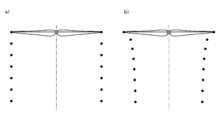
- the trajectory of the blade tip vortex of the rotor blade is shown.
- a) is a trajectory of the blade tip vortex of the rotor blade by the method of Adkins et al.
- b) is a trajectory of the blade tip vortex of the rotor blade by the Harada vortex method of the present inventor.
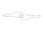
- FIG. 1 is a top view of a rotor blade according to an embodiment of the present invention. As shown in FIG. 1, the rotor blade 1 is provided on a hub 2 having a shaft hole 3.
- the method of Adkins et al. Can handle only a wake having a constant pitch and a constant radius, as shown in FIG.
- the vortex radius contracts as in the experiment as shown in FIG.
- a discharge vortex model in which the vortex to be concentrated is concentrated at the blade tip and the center of rotation by rolling up behind, a rotor blade 1 having the following form is obtained, and by using such a rotor blade 1 A high figure of merit is obtained.
- the rotor blade 1 has a solidity of 10% or less.
- the shape of the rotor blade 1 is as follows.
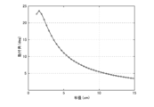
- FIG. 4 shows the chord length distribution when the Harada vortex method of the present inventor is optimized using the vortex model of FIG. 2 a), and FIG. 5 shows the mounting angle.
- Table 1 the calculation conditions are shown in Table 1.
- FIG. 4 shows the chord length of the root.
- Some commercially available drones cut the chord length at the base of this rotor blade to about 4 cm.
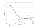
- FIG. 6 shows the chord length distribution when the Harada vortex method of the present inventor is optimized using the vortex model of FIG. 2 b), and
- FIG. 7 shows the mounting angle. The figure of merit at this time is 78.8%.
- the tangent line AB at the tip of the obtained chord length has a negative slope
- the tangent line CD at a radius of 65% has a positive slope
- the maximum value H is taken at point G.
- This H value is more than twice F.
- the obtained tangent IJ near the tip of the mounting angle has a positive value, takes a minimum value N at a point M near a radius of 60%, takes a maximum value P at a point O near a radius of 30%, and near the base.
- the tangent line KL has a negative value. Even with this shape, the chord length is 7 cm near the base of the wing.
- Harada's vortex method which is the present inventor, obtains a solution by minimizing the evaluation function, for example, a penalty function that increases when the chord length exceeds 4 cm is added to the evaluation function to limit the chord length. Can be imposed.
- the chord length at this time is shown in FIG. 8, and the mounting angle is shown in FIG.
- the figure of merit at this time is 78.6%.
- the tangent line AB at the tip of the obtained chord length has a negative gradient
- the tangent line CD at a radius of 65% has a positive gradient
- a local minimum at a point E near a radius of 60% Take F and take the maximum value H at point G near the root.
- This H value is more than twice F. Also, the obtained tangent IJ near the tip of the mounting angle has a positive value, takes a minimum value N at a point M near a radius of 60%, takes a maximum value P at a point O near a radius of 30%, and near the base.
- the tangent line KL has a negative value.
- the mounting angle is optimally set so as to maximize the figure of merit while limiting the chord length in this way, that is, attaching the root
- the rotor blade 1 according to this embodiment has a high figure of merit, and if used in a drone, helicopter, etc., the flight time and payload weight can be increased.
- the present invention can be applied to a fixed pitch coaxial double reversing rotor type manned helicopter, a fixed pitch coaxial double reversing rotor type unmanned helicopter, and the like.
- FIG. 10 shows the propeller coordinate system and the discharge vortex. It is considered that the propeller moves in the x-axis direction while rotating, and a discharge vortex is left in the moved locus.
- FIG. 11 shows an enlarged view of the first blade. There are i-th representative point from the axis of rotation on r i apart blades, j-th emission vortices are discretized into short line segments as shown in Fig white circles.
- the induced velocity in the x direction caused by the discharge vortex of the j-th unit intensity at the i-th representative point is X ij and the induced velocity in the z-direction is Z ij
- w i ⁇ Z ij ⁇ j (2)
- X ij and Z ij are constants obtained from Biosavart's law
- ⁇ j is the j-th emission vortex.
- FIG. 12 shows the cross section of the blade and the inflow speed.
- FIG. 13 shows the force acting on the blade blade element.
- c i 2 ⁇ i / C L V i (9)
- the local resistance dD i acting on the i th blade element is given by the following equation using the resistance coefficient C D.
- dD i 1/2 ⁇ ⁇ V i 2 C D c i db (10)
- C D but is a function of the Reynolds number and C L, using a constant C L, C D is good as a constant as a insensitive to Reynolds number.
- the axial component of the resultant force of the local lift dL i and the local resistance dD i is the local thrust dT i , and the tangential component is dN i .
- dT i dL i cos ⁇ i -dD i sin ⁇ i (11)
- T B ⁇ dT i (14)
- P B ⁇ dP i (15) Given in. Here, B is the number of blades.
Landscapes
- Engineering & Computer Science (AREA)
- Aviation & Aerospace Engineering (AREA)
- Physics & Mathematics (AREA)
- Fluid Mechanics (AREA)
- Mechanical Engineering (AREA)
- Structures Of Non-Positive Displacement Pumps (AREA)
- Toys (AREA)
Abstract
【課題】フィギュアオブメリットが高く、ドローン、ヘリコプタなどに使用すれば、飛行時間、ペイロード重量を増す事ができる。 【解決手段】ロータブレード1は、ソリディティが10%以下である。 ロータブレード1の形状は、以下の通りである。 (1)付け根付近に最大翼弦長を持ち、その値は半径50%から90%にある翼弦長の極小値の2倍以上であること。 (2)先端は徐々に細くなっていること。 (3)付け根の取付け角は半径30%付近以下の領域で付け根に行くほど減少していること。
Description
本発明は、ドローンやヘリコプタなどに用いられるロータブレード、そのようなロータブレードを有するドローン及びヘリコプタに関する。
近年、4発以上のロータブレードを持つドローンと呼ばれる飛行体が撮影、観測目的で盛んに利用されている。ドローンは通常プラスチック製の2枚羽の固定ピッチロータを使用しており、このロータブレードの性能によりペイロードの重さ及び飛行時間が左右される。ロータブレード形状は様々であり、単純テーパから古典プロペラ理論(非特許文献1)を応用したと思われる、付け根の翼弦長が広く、そこから先端に向けて急激に翼弦長を減らし、ある程度小さなテーパ比に移行し、先端を丸めた形状のものなどが見られる。
また有人小型ヘリコプタとしてGEN CORPORATIONが開発したGEN H-4(非特許文献2)同様に固定ピッチブレードを使用しており、ロータブレードに単純テーパを採用している。ヘリコプタの分野では英国のWestrand LinxがBERP(非特許文献3,特許文献1)と呼ばれる先端の翼弦長を拡大し、後退角を持たせたロータブレードを使用し、世界速度記録を達成している。本ロータブレードは先端の翼弦を拡大した不連続な前縁を飛行機で使用されるドッグツースとして機能させ、縦渦を発生させて上面の剥離を抑えることで後退側での揚力係数を稼ぐとともに、先端の後退角によって前進側での造波抵抗を減少させる事を目的としている。
ヘリコプタは単純運動理論とロータ回転面積と入力パワから求められる理論最大揚力で実際の揚力を除したフィギュアオブメリット(非特許文献4)と最大速度をトレードオフしなければならないため、ロータブレード形状は矩形か先端に弱いテーパがついた形状のものが多く使用されている。これに対してドローンはホバリングする時間が長いためフィギュアオブメリットの高いロータブレードを使用し、飛行時間及びペイロードを増加させようとする要求が高い。
Adkins, C. N., Liebeck, R. H., "Design of Optimum Propellers," AIAA-83-0190, Jan. 1983
柳沢 源内、二重反転一人乗りヘリコフターGEN H?4 開発と将来展望、Heli Japan 2002、 11月 2002
https://en.wikipedia.org/wiki/BERP_rotor
R. W. Prouty,"Helicopter Performance, Stability, and Control,"1990
フィギュアオブメリットの大きいロータブレードを設計する際に有効な手法としてAdkinsらの方法(非特許文献1)がある。しかしAdkinsらの方法は実際のロータブレードの後流に見られる縮流(筒状の流れの半径の縮小)や、渦巻き込み(ロールアップ)を反映できなかった。そのためフィギュアオブメリットは最大とはなっていなかった。
以上のような事情に鑑み、本発明の目的は、フィギュアオブメリットが高くする事ができるロータブレード、そのようなロータブレードを有するドローン及びヘリコプタを提供することにある。
上記課題を解決するために、本発明に係るロータブレードは、ソリディティが10%以下となるロータブレードであり、付け根付近に最大翼弦長を持ち、前記最大翼弦長の値は半径50%から90%にある翼弦長の極小値の2倍以上であり、先端は徐々に細くなっており、付け根の取付け角は半径30%付近以下の領域で付け根に行くほど減少している。
本発明に係るロータブレードは、実際のロータブレードの後流に見られる縮流(筒状の流れの半径の縮小)や渦巻き込み(ロールアップ)が反映された形状なので、フィギュアオブメリットが高くする事ができる。
本発明に係るロータブレードは、付け根付近に最大翼弦長を持ち、最大翼弦長の値は半径50%から90%にある翼弦長の極小値の2倍以上であり、その一方で、付け根の取付け角は半径30%付近以下の領域で付け根に行くほど減少している。これは、つまり翼弦長を実現可能な値におさめつつ、正確なロータ後流を用いて最適化を行って得られた形状であり、フィギュアオブメリットが高くする事ができる。
本発明に係るロータブレードは、実際のロータブレードの後流に見られる縮流(筒状の流れの半径の縮小)や渦巻き込み(ロールアップ)が反映された形状なので、フィギュアオブメリットが高くする事ができる。
本発明に係るロータブレードは、付け根付近に最大翼弦長を持ち、最大翼弦長の値は半径50%から90%にある翼弦長の極小値の2倍以上であり、その一方で、付け根の取付け角は半径30%付近以下の領域で付け根に行くほど減少している。これは、つまり翼弦長を実現可能な値におさめつつ、正確なロータ後流を用いて最適化を行って得られた形状であり、フィギュアオブメリットが高くする事ができる。
本発明の別形態に係るドローンは、上記構成のロータブレードを有する。
本発明の更に別形態に係るヘリコプタは、上記構成のロータブレードを有する。
本発明の更に別形態に係るヘリコプタは、上記構成のロータブレードを有する。
本発明により、フィギュアオブメリットが高く、ドローン、ヘリコプタなどに使用すれば、飛行時間、ペイロード重量を増す事ができる。
以下、図面を参照しながら、本発明の実施形態を説明する。
図1は本発明の一実施形態に係るロータブレードの上面図である。
図1に示すように、ロータブレード1は、シャフト穴3を有するハブ2に設けられている。
図1は本発明の一実施形態に係るロータブレードの上面図である。
図1に示すように、ロータブレード1は、シャフト穴3を有するハブ2に設けられている。
ここで、Adkinsらの方法では図2のa)に示す、一定ピッチかつ一定半径の後流しか扱えない。これに対して、本発明者である原田の渦法(後述する)では図2のb)に示すように渦半径が実験と同様に収縮し、かつ図3に示すようにロータブレード1から放出する渦が後方でロールアップにより翼端と回転中心に集中する放出渦モデルを適用する事で、以下の形態を特徴するロータブレード1を得、そのような形態のロータブレード1を使用する事で高いフィギュアオブメリットを得るものである。
ロータブレード1は、ソリディティが10%以下である。
ロータブレード1の形状は、以下の通りである。
(1)付け根付近に最大翼弦長を持ち、その値は半径50%から90%にある翼弦長の極小値の2倍以上であること。
(2)先端は徐々に細くなっていること。
(3)付け根の取付け角は半径30%付近以下の領域で付け根に行くほど減少していること。
図4に本発明者である原田の渦法を図2のa)の渦モデルを用いて最適化した際の翼弦長分布を、また図5に取付角を示す。ここで計算条件を表1に示す。
ロータブレード1は、ソリディティが10%以下である。
ロータブレード1の形状は、以下の通りである。
(1)付け根付近に最大翼弦長を持ち、その値は半径50%から90%にある翼弦長の極小値の2倍以上であること。
(2)先端は徐々に細くなっていること。
(3)付け根の取付け角は半径30%付近以下の領域で付け根に行くほど減少していること。
図4に本発明者である原田の渦法を図2のa)の渦モデルを用いて最適化した際の翼弦長分布を、また図5に取付角を示す。ここで計算条件を表1に示す。
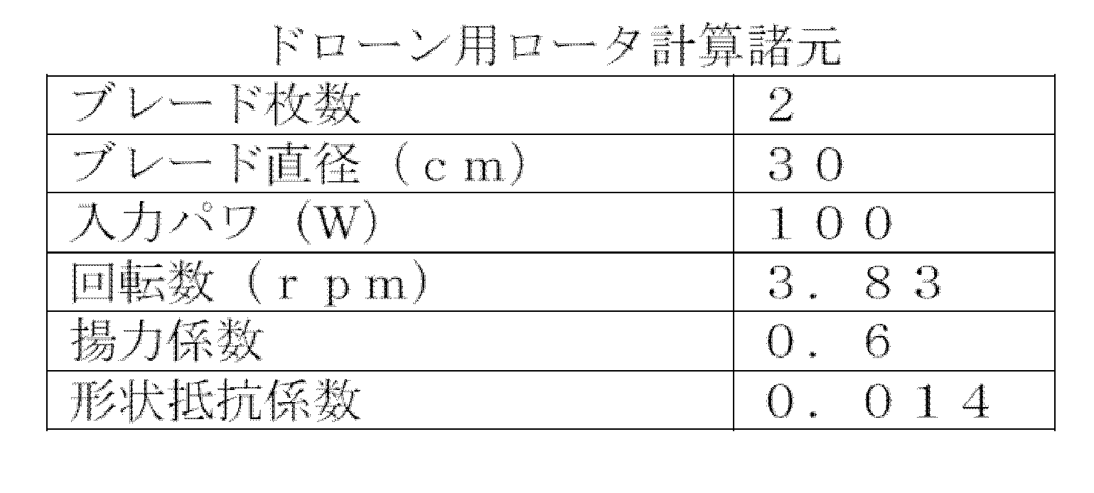
図4に示すように付け根の翼弦長が7.5cmに達しているため、実際的ではない。市販のドローンの中にはこのロータブレードの付け根の翼弦長を4cm程度に切り落として使用している例がある。
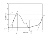
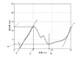
図6に本発明者である原田の渦法を図2のb)の渦モデルを用いて最適化した際の翼弦長分布を、また図7に取付角を示す。このときのフィギュアオブメリットは78.8%である。
図6に本発明者である原田の渦法を図2のb)の渦モデルを用いて最適化した際の翼弦長分布を、また図7に取付角を示す。このときのフィギュアオブメリットは78.8%である。
得られた翼弦長の先端の接線ABは負の勾配を持ち、半径65%付近での接線CDは正の勾配を持ち、半径60%付近の点Eにおいて極小値Fをとり、付け根付近の点Gで最大値Hをとる。
このHの値はFの2倍以上である。また得られた取付角の先端付近の接線IJは正の値を持ち、半径60%付近の点Mで極小値Nをとり、半径30%付近の点Oで極大値Pをとり、付け根付近の接線KLは負の値を持つ。この形状でも翼付け根付近で翼弦長が7cmとなる。
本発明者である原田の渦法は評価関数を最小化する事で解を得るので例えば翼弦長が4cmを超えるときに値が大きくなるペナルティ関数を評価関数に加えることで翼弦長の制限を課す事ができる。このときの翼弦長を図8に、取付角を図9に示す。このときのフィギュアオブメリットは78.6%である。
先の結果と同様に、得られた翼弦長の先端の接線ABは負の勾配を持ち、半径65%付近での接線CDは正の勾配を持ち、半径60%付近の点Eにおいて極小値Fをとり、付け根付近の点Gで最大値Hをとる。
このHの値はFの2倍以上である。また得られた取付角の先端付近の接線IJは正の値を持ち、半径60%付近の点Mで極小値Nをとり、半径30%付近の点Oで極大値Pをとり、付け根付近の接線KLは負の値を持つ。
ここで、代表的なドローンのロータの諸元を用いて計算したところ、実用性の観点より、翼弦長を極小値の2倍に制限した時は0.3%のフィギュアオブメリットの低下、翼弦長を極小値の1.5倍に制限した時は1.0%のフィギュアオブメリットの低下が見られた。これに対して、本発明に係るロータブレード1では、このように翼弦長を制限しながらその中でフィギュアオブメリットを最大にする様に取付け角を最適に設定することで、すなわち付根の取付け角を半径30%付近以下の領域で付根に行くほど減少させることで、翼弦制限によるフィギュアオブメリットの低下をこの項で最小限に抑えることができる。
従って、この実施形態に係るロータブレード1は、フィギュアオブメリットが高く、ドローン、ヘリコプタなどに使用すれば、飛行時間、ペイロード重量を増す事ができる。
本発明は、固定ピッチ同軸2重反転ロータ式有人ヘリコプタや固定ピッチ同軸2重反転ロータ式無人ヘリコプタなどに適用する事ができる。
従って、この実施形態に係るロータブレード1は、フィギュアオブメリットが高く、ドローン、ヘリコプタなどに使用すれば、飛行時間、ペイロード重量を増す事ができる。
本発明は、固定ピッチ同軸2重反転ロータ式有人ヘリコプタや固定ピッチ同軸2重反転ロータ式無人ヘリコプタなどに適用する事ができる。
次に、上述した原田の渦法を説明する。
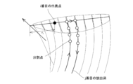
図10にプロペラの座標系と放出渦を示す。プロペラは回転しながらx軸方向に移動し、移動した軌跡に放出渦が残されると考える。
図11に一枚目のブレードの拡大図を示す。回転軸からri離れたブレード上にi番目の代表点があり、j番目の放出渦は図中白丸で示された様に短い線分に離散化する。j番目の単位強度の放出渦がi番目の代表点に引き起こすx方向の誘導速度をXij、z方向の誘導速度をZijとすると、i番目の代表点に引き起こされるx方向の誘導速度ui、z方向の誘導速度wiはそれぞれ
ui=ΣXijгj (1)
wi=ΣZijгj (2)
で与えられる。ここで、Xij、Zijはビオサバールの法則から得られる定数であり、гjはj番目の放出渦である。
図10にプロペラの座標系と放出渦を示す。プロペラは回転しながらx軸方向に移動し、移動した軌跡に放出渦が残されると考える。
図11に一枚目のブレードの拡大図を示す。回転軸からri離れたブレード上にi番目の代表点があり、j番目の放出渦は図中白丸で示された様に短い線分に離散化する。j番目の単位強度の放出渦がi番目の代表点に引き起こすx方向の誘導速度をXij、z方向の誘導速度をZijとすると、i番目の代表点に引き起こされるx方向の誘導速度ui、z方向の誘導速度wiはそれぞれ
ui=ΣXijгj (1)
wi=ΣZijгj (2)
で与えられる。ここで、Xij、Zijはビオサバールの法則から得られる定数であり、гjはj番目の放出渦である。
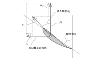
図12にブレードの断面と流入速度を示す。ブレードに流入する空気の接線方向成分をUTとするとUTは
UT=riΩ-wi (3)
で与えられる。ここでΩはプロペラの回転角速度である。またブレードに流入する空気の軸方向成分をUPとするとUPは
UP=U-ui (4)
で与えられる。ここでUはプロペラの前進速度である。流入角φi及び流入速度Viはそれぞれ次式で与えられる。
φi=tan-1(UP/UT) (5)
Vi=√(UP 2+UT 2) (6)
UT=riΩ-wi (3)
で与えられる。ここでΩはプロペラの回転角速度である。またブレードに流入する空気の軸方向成分をUPとするとUPは
UP=U-ui (4)
で与えられる。ここでUはプロペラの前進速度である。流入角φi及び流入速度Viはそれぞれ次式で与えられる。
φi=tan-1(UP/UT) (5)
Vi=√(UP 2+UT 2) (6)
図13にブレード翼素に働く力を示す。i番目の翼素に働く局所揚力dLiはクッタ=ジューコフスキーの定理により
dLi=ρViгidb (7)
で与えられる。ここでρは空気密度、dbは翼素の幅である。または、揚力係数CLを用いて
dLi=1/2・ρVi 2CLcidb (8)
で表される。ここで、ciはi番目の翼素の翼弦長である。(7)、(8)式よりciは次式で与えられる。
ci=2гi/CLVi (9)
i番目の翼素に働く局所抵抗dDiは抵抗係数CDを用いて次式で与えられる。
dDi=1/2・ρVi 2CDcidb (10)
CDはレイノルズ数とCLの関数であるが、CLに定数を用い、CDがレイノルズ数に対しては鈍感であるとして定数としてよい。
局所揚力dLiと局所抵抗dDiの合力の軸方向分力は局所推力dTiとなり、接線方向分力をdNiとするとそれぞれ、
dTi=dLicosφi-dDisinφi (11)
dNi=dLisinφi+dDicosφi (12)
となる。局所吸収パワdPiはdNiriΩであるから次式で与えられる。
dPi=(dLisinφi+dDicosφi)riΩ (13)
結局、推力と吸収パワは(11)式と(13)式よりそれぞれ
T=BΣdTi (14)
P=BΣdPi (15)
で与えられる。ここでBはブレード枚数である。
dLi=ρViгidb (7)
で与えられる。ここでρは空気密度、dbは翼素の幅である。または、揚力係数CLを用いて
dLi=1/2・ρVi 2CLcidb (8)
で表される。ここで、ciはi番目の翼素の翼弦長である。(7)、(8)式よりciは次式で与えられる。
ci=2гi/CLVi (9)
i番目の翼素に働く局所抵抗dDiは抵抗係数CDを用いて次式で与えられる。
dDi=1/2・ρVi 2CDcidb (10)
CDはレイノルズ数とCLの関数であるが、CLに定数を用い、CDがレイノルズ数に対しては鈍感であるとして定数としてよい。
局所揚力dLiと局所抵抗dDiの合力の軸方向分力は局所推力dTiとなり、接線方向分力をdNiとするとそれぞれ、
dTi=dLicosφi-dDisinφi (11)
dNi=dLisinφi+dDicosφi (12)
となる。局所吸収パワdPiはdNiriΩであるから次式で与えられる。
dPi=(dLisinφi+dDicosφi)riΩ (13)
結局、推力と吸収パワは(11)式と(13)式よりそれぞれ
T=BΣdTi (14)
P=BΣdPi (15)
で与えられる。ここでBはブレード枚数である。
プロペラの最適設計問題はCL、CD、Ω、設計パワP0を設定し、гiを未知数として、
[条件]:P=P0
のもとで
[目的関数]:-T
を最小化する
最適化問題に帰着する。
[条件]:P=P0
のもとで
[目的関数]:-T
を最小化する
最適化問題に帰着する。
1 ロータブレード
2 ハブ
3 シャフト穴
2 ハブ
3 シャフト穴
Claims (3)
- ソリディティが10%以下となるロータブレードであり、
前記ロータブレードの形状が、
付け根付近に最大翼弦長を持ち、前記最大翼弦長の値は半径50%から90%にある翼弦長の極小値の2倍以上であり、
先端は徐々に細くなっており、
付け根の取付け角は半径30%付近以下の領域で付け根に行くほど減少している
ロータブレード。 - 請求項1に記載のロータブレードを有するドローン。
- 請求項1に記載のロータブレードを有するヘリコプタ。
Priority Applications (1)
| Application Number | Priority Date | Filing Date | Title |
|---|---|---|---|
| JP2018501694A JP6778440B2 (ja) | 2016-02-23 | 2017-02-21 | ロータブレード、ドローン、ヘリコプタ及びロータブレードの設計方法 |
Applications Claiming Priority (4)
| Application Number | Priority Date | Filing Date | Title |
|---|---|---|---|
| JP2016-031659 | 2016-02-23 | ||
| JP2016031659 | 2016-02-23 | ||
| PCT/JP2017/001030 WO2017145563A1 (ja) | 2016-02-23 | 2017-01-13 | ロータブレード、ドローン及びヘリコプタ |
| JPPCT/JP2017/001030 | 2017-01-13 |
Publications (1)
| Publication Number | Publication Date |
|---|---|
| WO2017146028A1 true WO2017146028A1 (ja) | 2017-08-31 |
Family
ID=59685058
Family Applications (2)
| Application Number | Title | Priority Date | Filing Date |
|---|---|---|---|
| PCT/JP2017/001030 Ceased WO2017145563A1 (ja) | 2016-02-23 | 2017-01-13 | ロータブレード、ドローン及びヘリコプタ |
| PCT/JP2017/006310 Ceased WO2017146028A1 (ja) | 2016-02-23 | 2017-02-21 | ロータブレード、ドローン及びヘリコプタ |
Family Applications Before (1)
| Application Number | Title | Priority Date | Filing Date |
|---|---|---|---|
| PCT/JP2017/001030 Ceased WO2017145563A1 (ja) | 2016-02-23 | 2017-01-13 | ロータブレード、ドローン及びヘリコプタ |
Country Status (2)
| Country | Link |
|---|---|
| JP (1) | JP6778440B2 (ja) |
| WO (2) | WO2017145563A1 (ja) |
Cited By (1)
| Publication number | Priority date | Publication date | Assignee | Title |
|---|---|---|---|---|
| KR20230028401A (ko) | 2020-06-30 | 2023-02-28 | 소니그룹주식회사 | 프로펠러, 비행 물체 및 프로펠러의 제조방법 |
Families Citing this family (2)
| Publication number | Priority date | Publication date | Assignee | Title |
|---|---|---|---|---|
| CN206243477U (zh) * | 2016-11-10 | 2017-06-13 | 中强光电股份有限公司 | 飞行器及其旋翼 |
| JP6856930B2 (ja) * | 2017-02-15 | 2021-04-14 | 国立研究開発法人宇宙航空研究開発機構 | ロータ、ドローン及びヘリコプタ |
Citations (3)
| Publication number | Priority date | Publication date | Assignee | Title |
|---|---|---|---|---|
| GB752080A (en) * | 1952-07-18 | 1956-07-04 | Aristides Warto | Improvements in or relating to rotor blades for helicopters |
| US5174721A (en) * | 1990-10-13 | 1992-12-29 | Westland Helicopters Limited | Helicopter rotor blades |
| JP2009173152A (ja) * | 2008-01-24 | 2009-08-06 | Mitsubishi Heavy Ind Ltd | ヘリコプタ、そのロータ、及びその制御方法 |
-
2017
- 2017-01-13 WO PCT/JP2017/001030 patent/WO2017145563A1/ja not_active Ceased
- 2017-02-21 WO PCT/JP2017/006310 patent/WO2017146028A1/ja not_active Ceased
- 2017-02-21 JP JP2018501694A patent/JP6778440B2/ja active Active
Patent Citations (3)
| Publication number | Priority date | Publication date | Assignee | Title |
|---|---|---|---|---|
| GB752080A (en) * | 1952-07-18 | 1956-07-04 | Aristides Warto | Improvements in or relating to rotor blades for helicopters |
| US5174721A (en) * | 1990-10-13 | 1992-12-29 | Westland Helicopters Limited | Helicopter rotor blades |
| JP2009173152A (ja) * | 2008-01-24 | 2009-08-06 | Mitsubishi Heavy Ind Ltd | ヘリコプタ、そのロータ、及びその制御方法 |
Cited By (3)
| Publication number | Priority date | Publication date | Assignee | Title |
|---|---|---|---|---|
| KR20230028401A (ko) | 2020-06-30 | 2023-02-28 | 소니그룹주식회사 | 프로펠러, 비행 물체 및 프로펠러의 제조방법 |
| DE112021003459T5 (de) | 2020-06-30 | 2023-04-06 | Sony Group Corporation | Propeller, Flugobjekt und Verfahren zur Herstellung eines Propellers |
| US12054248B2 (en) | 2020-06-30 | 2024-08-06 | Sony Group Corporation | Propeller, flying object, and method for manufacturing propeller |
Also Published As
| Publication number | Publication date |
|---|---|
| JP6778440B2 (ja) | 2020-11-04 |
| JPWO2017146028A1 (ja) | 2018-12-13 |
| WO2017145563A1 (ja) | 2017-08-31 |
Similar Documents
| Publication | Publication Date | Title |
|---|---|---|
| Pereira | Hover and wind-tunnel testing of shrouded rotors for improved micro air vehicle design | |
| Gur et al. | Comparison between blade-element models of propellers | |
| US5131604A (en) | Helicopter antitorque device | |
| JP7116459B2 (ja) | ダクテッドファン、マルチコプタ、垂直離着陸機、cpu冷却用ファン及びラジエータ冷却用ファン | |
| US10988245B2 (en) | Segmented duct for tilting proprotors | |
| JP5078883B2 (ja) | 高速回転翼航空機のロータブレード | |
| Ning et al. | An experimental study on the aerodynamic and aeroacoustic performances of a bio-inspired UAV propeller | |
| CA3060758C (en) | Aircraft with rotating ducted fan | |
| EP3077283B1 (en) | Boundary layer ingesting blade | |
| US20110052392A1 (en) | Method of flight in an expanded speed range using thrust vectoring propellers | |
| JPS62299466A (ja) | プロペラ | |
| JP6856930B2 (ja) | ロータ、ドローン及びヘリコプタ | |
| JP6778440B2 (ja) | ロータブレード、ドローン、ヘリコプタ及びロータブレードの設計方法 | |
| CN105940189A (zh) | 叶片导流器 | |
| US11214364B2 (en) | Main rotor blade and helicopter | |
| US6899525B2 (en) | Blade and wing configuration | |
| Sapit et al. | Aerodynamics drone propeller analysis by using computational fluid dynamics | |
| CN111498108A (zh) | 一种适用于多旋翼高速飞行的高效桨叶 | |
| CN106218886B (zh) | 多旋翼机桨叶以及多旋翼机 | |
| CN112977816A (zh) | 旋翼飞行器的桨叶及旋翼飞行器 | |
| Sandak et al. | Aeroelastically adaptive propeller using blades’ root flexibility | |
| Liu et al. | Aerodynamics properties and design method of high efficiency-light propeller of stratospheric airships | |
| Pereira et al. | Hover Tests of Micro Aerial Vehicle‐Scale Shrouded Rotors, Part II: Flow Field Measurements | |
| CN110077580A (zh) | 一种航行器 | |
| CN105691596B (zh) | 一种类三角布局高空螺旋桨 |
Legal Events
| Date | Code | Title | Description |
|---|---|---|---|
| ENP | Entry into the national phase |
Ref document number: 2018501694 Country of ref document: JP Kind code of ref document: A |
|
| NENP | Non-entry into the national phase |
Ref country code: DE |
|
| 121 | Ep: the epo has been informed by wipo that ep was designated in this application |
Ref document number: 17756466 Country of ref document: EP Kind code of ref document: A1 |
|
| 122 | Ep: pct application non-entry in european phase |
Ref document number: 17756466 Country of ref document: EP Kind code of ref document: A1 |