WO2017145756A1 - Dispositif de génération de fichiers, procédé de génération de fichiers, dispositif de reproduction et procédé de reproduction - Google Patents
Dispositif de génération de fichiers, procédé de génération de fichiers, dispositif de reproduction et procédé de reproduction Download PDFInfo
- Publication number
- WO2017145756A1 WO2017145756A1 PCT/JP2017/004531 JP2017004531W WO2017145756A1 WO 2017145756 A1 WO2017145756 A1 WO 2017145756A1 JP 2017004531 W JP2017004531 W JP 2017004531W WO 2017145756 A1 WO2017145756 A1 WO 2017145756A1
- Authority
- WO
- WIPO (PCT)
- Prior art keywords
- file
- image
- depth
- quality
- quality information
- Prior art date
Links
Images


Classifications
-
- H—ELECTRICITY
- H04—ELECTRIC COMMUNICATION TECHNIQUE
- H04N—PICTORIAL COMMUNICATION, e.g. TELEVISION
- H04N13/00—Stereoscopic video systems; Multi-view video systems; Details thereof
- H04N13/20—Image signal generators
- H04N13/275—Image signal generators from 3D object models, e.g. computer-generated stereoscopic image signals
-
- G—PHYSICS
- G02—OPTICS
- G02B—OPTICAL ELEMENTS, SYSTEMS OR APPARATUS
- G02B30/00—Optical systems or apparatus for producing three-dimensional [3D] effects, e.g. stereoscopic images
- G02B30/40—Optical systems or apparatus for producing three-dimensional [3D] effects, e.g. stereoscopic images giving the observer of a single two-dimensional [2D] image a perception of depth
-
- G—PHYSICS
- G06—COMPUTING; CALCULATING OR COUNTING
- G06T—IMAGE DATA PROCESSING OR GENERATION, IN GENERAL
- G06T1/00—General purpose image data processing
-
- G—PHYSICS
- G06—COMPUTING; CALCULATING OR COUNTING
- G06T—IMAGE DATA PROCESSING OR GENERATION, IN GENERAL
- G06T1/00—General purpose image data processing
- G06T1/0007—Image acquisition
-
- H—ELECTRICITY
- H04—ELECTRIC COMMUNICATION TECHNIQUE
- H04N—PICTORIAL COMMUNICATION, e.g. TELEVISION
- H04N13/00—Stereoscopic video systems; Multi-view video systems; Details thereof
-
- H—ELECTRICITY
- H04—ELECTRIC COMMUNICATION TECHNIQUE
- H04N—PICTORIAL COMMUNICATION, e.g. TELEVISION
- H04N13/00—Stereoscopic video systems; Multi-view video systems; Details thereof
- H04N13/10—Processing, recording or transmission of stereoscopic or multi-view image signals
- H04N13/106—Processing image signals
- H04N13/172—Processing image signals image signals comprising non-image signal components, e.g. headers or format information
- H04N13/178—Metadata, e.g. disparity information
-
- H—ELECTRICITY
- H04—ELECTRIC COMMUNICATION TECHNIQUE
- H04N—PICTORIAL COMMUNICATION, e.g. TELEVISION
- H04N21/00—Selective content distribution, e.g. interactive television or video on demand [VOD]
- H04N21/20—Servers specifically adapted for the distribution of content, e.g. VOD servers; Operations thereof
- H04N21/23—Processing of content or additional data; Elementary server operations; Server middleware
- H04N21/236—Assembling of a multiplex stream, e.g. transport stream, by combining a video stream with other content or additional data, e.g. inserting a URL [Uniform Resource Locator] into a video stream, multiplexing software data into a video stream; Remultiplexing of multiplex streams; Insertion of stuffing bits into the multiplex stream, e.g. to obtain a constant bit-rate; Assembling of a packetised elementary stream
- H04N21/2362—Generation or processing of Service Information [SI]
-
- H—ELECTRICITY
- H04—ELECTRIC COMMUNICATION TECHNIQUE
- H04N—PICTORIAL COMMUNICATION, e.g. TELEVISION
- H04N5/00—Details of television systems
- H04N5/76—Television signal recording
-
- H—ELECTRICITY
- H04—ELECTRIC COMMUNICATION TECHNIQUE
- H04N—PICTORIAL COMMUNICATION, e.g. TELEVISION
- H04N5/00—Details of television systems
- H04N5/76—Television signal recording
- H04N5/91—Television signal processing therefor
-
- H—ELECTRICITY
- H04—ELECTRIC COMMUNICATION TECHNIQUE
- H04N—PICTORIAL COMMUNICATION, e.g. TELEVISION
- H04N9/00—Details of colour television systems
- H04N9/79—Processing of colour television signals in connection with recording
- H04N9/80—Transformation of the television signal for recording, e.g. modulation, frequency changing; Inverse transformation for playback
- H04N9/82—Transformation of the television signal for recording, e.g. modulation, frequency changing; Inverse transformation for playback the individual colour picture signal components being recorded simultaneously only
- H04N9/8205—Transformation of the television signal for recording, e.g. modulation, frequency changing; Inverse transformation for playback the individual colour picture signal components being recorded simultaneously only involving the multiplexing of an additional signal and the colour video signal
-
- H—ELECTRICITY
- H04—ELECTRIC COMMUNICATION TECHNIQUE
- H04N—PICTORIAL COMMUNICATION, e.g. TELEVISION
- H04N13/00—Stereoscopic video systems; Multi-view video systems; Details thereof
- H04N2013/0074—Stereoscopic image analysis
- H04N2013/0081—Depth or disparity estimation from stereoscopic image signals
Definitions
- the present disclosure relates to a file generation device, a file generation method, a reproduction device, and a reproduction method, and more particularly, a file that efficiently stores quality information of depth-related images including at least depth images can be generated.
- the present invention relates to a file generation device, a file generation method, a playback device, and a playback method.
- the depth image is an image having a pixel value as a value representing the position of each pixel in the depth direction of the subject.
- an occlusion image may be used as additional information in order to realize natural stereoscopic vision.
- the occlusion image is a texture image of an occlusion area that is an area of a subject that does not exist in the texture image, that is, a subject that cannot be seen from the viewpoint of the texture image (for example, a subject hidden by a subject in front).
- the texture image and the depth image can be transmitted by, for example, the existing MPEG-DASH (Moving Picture Experts Group Dynamic Dynamic Adaptive Streaming over HTTP standard) system (see, for example, Non-Patent Document 1).
- MPEG-DASH Motion Picture Experts Group Dynamic Dynamic Adaptive Streaming over HTTP standard
- the DASH client selects and obtains the maximum allowable bit rate depth image from the multiple bit rate depth images stored in the DASH server in consideration of the transmission path and the buffer capacity of the DASH client. To do.
- the image quality of the 3D image does not change much depending on the bit rate of the depth image. Therefore, in this case, if the DASH client selects and acquires a depth image having the maximum allowable bit rate, the transmission path and the buffer are wasted.
- quality information is stored in a file as well as a depth-related image including at least a depth image, and the DASH client acquires a depth-related image with an appropriate bit rate using the quality information. It is desired. However, it is not considered that the quality information of the depth related image is efficiently stored in the file.
- the present disclosure has been made in view of such a situation, and makes it possible to generate a file that efficiently stores quality information of a depth-related image including at least a depth image.
- a file generation device is a file generation device including a file generation unit that generates a file that divides and arranges quality information representing the quality of a depth-related image including a depth image for each type. .
- the file generation method according to the first aspect of the present disclosure corresponds to the file generation apparatus according to the first aspect of the present disclosure.
- a file is generated in which quality information representing the quality of a depth-related image including at least a depth image is divided and arranged for each type.
- the playback device includes an acquisition unit that acquires the quality information of a predetermined type from a file that divides and arranges quality information representing the quality of a depth-related image including a depth image for each type. Is a playback device.
- the playback method according to the second aspect of the present disclosure corresponds to the playback device according to the second aspect of the present disclosure.
- the quality information of a predetermined type is acquired from a file in which quality information representing the quality of a depth-related image including at least a depth image is divided and arranged for each type.
- the file generation device can be realized by causing a computer to execute a program.
- a program to be executed by a computer is transmitted through a transmission medium or recorded on a recording medium. And can be provided.
- a file can be generated. Further, according to the first aspect of the present disclosure, it is possible to generate a file that efficiently stores the quality information of the depth related image including at least the depth image.
- the quality information can be acquired from a file that efficiently stores the quality information of the depth related image including at least the depth image.
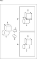
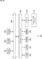
- FIG. 26 is a diagram illustrating a configuration example of a sample of the track in FIG. 25. It is a figure which shows the structural example of the moov box of a depth file. It is a figure which shows the example of description of QualityMetricsConfigurationBox.
- First embodiment Information processing system (FIGS. 1 to 15) 2.
- Second embodiment Information processing system (FIG. 16) 3.
- Third embodiment Information processing system (FIGS. 17 to 20) 4).
- Fourth embodiment Information processing system (FIG. 21) 5).
- Fifth embodiment Information processing system (FIG. 22) 6).
- Sixth embodiment information processing system (FIGS. 23 and 24) 7).
- Seventh embodiment Information processing system (FIGS. 25 to 32) 8).
- Eighth embodiment information processing system (FIGS. 33 and 39) 9. Ninth Embodiment: Computer (FIG. 40)
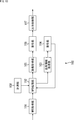
- FIG. 1 is a diagram illustrating an overview of an information processing system according to the first embodiment to which the present disclosure is applied.
- the information processing system 10 in FIG. 1 is configured by connecting a Web server 12 as a DASH server connected to a file generation device 11 and a moving image playback terminal 14 as a DASH client via the Internet 13.
- the Web server 12 distributes the moving image content file generated by the file generation device 11 to the moving image playback terminal 14 in accordance with the MPEG-DASH method.
- the file generation device 11 receives one or more bits each of the texture image, the depth image, the image data of the occlusion image, the audio data, the metadata including the quality information of the depth image and the occlusion image, and the like. Encode with rate.
- the texture image has two bit rates of 8 Mbps and 4 Mbps
- the depth image has two bit rates of 2 Mbps and 1 Mpbs
- the occlusion image has one bit rate of 1 Mpbs. To do.
- a depth occlusion image when it is not necessary to distinguish between the depth image and the occlusion image, they are collectively referred to as a depth occlusion image.
- the file generation device 11 converts the encoded image data and audio data streams of each bit rate generated as a result of encoding into files in the ISO base media file format in units of several seconds to about 10 seconds called segments. .
- the file generation device 11 uploads a segment file, which is an MP4 file of image data and audio data generated as a result, to the Web server 12.
- the file generation device 11 divides the encoded stream of metadata including the quality information of the depth occlusion image in segment units for each type of depth occlusion image, and files it in the ISO base media file format.
- the file generation device 11 uploads the metadata segment file generated as a result to the Web server 12.
- the file generation device 11 also generates an MPD (Media Presentation Description) file (management file) that manages a segment file group of moving image content.
- the file generation device 11 uploads the MPD file to the Web server 12.
- the Web server 12 stores the segment file and MPD file uploaded from the file generation device 11.
- the web server 12 transmits the stored segment file or MPD file to the video playback terminal 14 in response to a request from the video playback terminal 14.
- the video playback terminal 14 includes streaming data control software (hereinafter referred to as control software) 21, video playback software 22, and client software (hereinafter referred to as HTTP (HyperText Transfer Protocol) access). 23) (referred to as access software).
- control software streaming data control software
- video playback software video playback software 22
- client software hereinafter referred to as HTTP (HyperText Transfer Protocol) access. 23
- the control software 21 is software that controls data streamed from the Web server 12. Specifically, the control software 21 causes the video playback terminal 14 to acquire an MPD file from the Web server 12.
- control software 21 is based on the MPD file and the reproduction target information indicating the reproduction target time, bit rate, etc. designated by the moving image reproduction software 22, and the encoded stream of the segment file to be reproduced.
- a transmission request is commanded to the access software 23.
- the moving image reproduction software 22 is software for reproducing the encoded stream acquired from the Web server 12. Specifically, the moving image reproduction software 22 designates the reproduction target information for reproducing the encoded metadata stream to the control software 21. When the moving image reproduction software 22 receives the notification of the start of reception of the encoded metadata stream from the access software 23, the moving image reproduction software 22 decodes the encoded metadata stream received by the moving image reproduction terminal 14.
- the video playback software 22 plays back an encoded stream of image data or audio data of a predetermined bit rate based on quality information included in the metadata obtained as a result of decoding, the network bandwidth of the Internet 13, and the like.
- the target information is designated to the control software 21. Then, when the moving image reproduction software 22 receives the notification of the start of reception of the encoded stream of image data and audio data from the access software 23, the moving image reproduction software 22 encodes the image data and audio data received by the moving image reproduction terminal 14. Decode the stream.
- the video playback software 22 outputs the image data of the texture image obtained as a result of decoding as it is.
- the moving image reproduction software 22 generates and outputs 3D image data using the texture image and the depth image.
- the moving image reproduction software 22 generates and outputs 3D image data using the texture image, the depth image, and the occlusion image.
- the moving image reproduction software 22 outputs audio data obtained as a result of decoding.
- the access software 23 is software that controls communication with the Web server 12 via the Internet 13 using HTTP. Specifically, the access software 23 causes the moving image playback terminal 14 to transmit a transmission request for the encoded stream of the segment file to be played back in response to a command from the control software 21. Further, the access software 23 causes the video playback terminal 14 to start receiving the encoded stream transmitted from the Web server 12 in response to the transmission request, and supplies the video playback software 22 with a reception start notification. .
- FIG. 2 is a diagram illustrating an occlusion image.
- the texture image 62 photographed from the direction of looking from the left indicated by the arrow 52 using the texture image 61 and the depth image of the texture image 61, first, based on the depth image of the texture image 61, the texture The pixel value of the texture image 61 corresponding to each pixel of the image 62 is acquired. And the texture image 62 is produced
- the texture image 62 does not have a corresponding texture image 61, that is, not photographed when photographing from the direction indicated by the arrow 51, but the direction indicated by the arrow 52.
- an occlusion area 43 that is an area of a subject to be photographed (in the example of FIG. 2, the side surface of the cube 42) is generated.
- the texture image of the occlusion area 43 is an occlusion image.
- a texture image 62 having a viewpoint different from that of the texture image 61 can be generated. Further, the depth image of the texture image 62 can be generated from the texture image 62 and the depth image of the texture image 61. Therefore, it is possible to generate a 3D image having a different viewpoint from the texture image 61 from the texture image 62 and the depth image of the texture image 62.
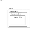
- FIG. 3 is a diagram for explaining the hierarchical structure of the MPD file.
- information such as video content encoding method, bit rate, image size, audio language, etc. are layered and described in XML format.
- the MPD file hierarchically includes elements such as a period (Period), an adaptation set (AdaptationSet), a representation (Representation), and segment info (SegmentInfo). .
- the video content managed by the user is divided in a predetermined time range (for example, a unit such as a program or CM (Commercial)).
- the period element is described for each divided moving image content.
- the period element includes the playback start time of the video content program (a set of synchronized image data, audio data, etc.), and the URL (Uniform Resource Locator) of the Web server 12 that stores the segment file of the video content. Have information.
- the adaptation set element is included in the period element, and groups the representation elements corresponding to the segment file group of the same encoded stream of the moving image content corresponding to the period element.
- the representation elements are grouped according to the data type of the corresponding encoded stream, for example.
- the adaptation set element has uses such as media type, language, subtitles or dubbing common to the group.
- the representation element is included in the adaptation set element that groups the representation elements, and is described for each segment file group of the same encoded stream of the moving image content corresponding to the upper layer period element.
- the representation element has a bit rate common to the segment file group, an image size, and the like.
- the segment info element is included in the representation element and has information on each segment file of the segment file group corresponding to the representation.
- FIG. 4 is a block diagram illustrating a configuration example of the file generation apparatus in FIG.
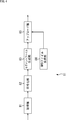
- an acquisition unit 81 includes an acquisition unit 81, an encoding unit 82, a segment file generation unit 83, an MPD file generation unit 84, and an upload unit 85.
- the acquisition unit 81 of the file generation apparatus 11 acquires the image data of the texture image, depth image, and occlusion image of the moving image content, and supplies the image data to the encoding unit 82.
- the acquisition unit 81 acquires metadata including quality information of encoded streams of 2 Mbps and 1 Mbps depth images and 1 Mbps occlusion images, and supplies the metadata to the encoding unit 82.
- the encoding unit 82 encodes the image data of the texture image supplied from the acquisition unit 81 at 8 Mbps and 4 Mbps, and encodes the image data of the depth image at 2 Mbps and 1 Mbps.
- the encoding unit 82 encodes the image data of the occlusion image at 1 Mbps. Further, the encoding unit 82 encodes metadata of 2 Mbps and 1 Mbps depth images and 1 Mbps occlusion images, respectively, at a predetermined bit rate.
- the encoding unit 82 supplies the encoded stream generated as a result of the encoding to the segment file generation unit 83.
- the segment file generation unit 83 converts the encoded stream of the texture image, depth image, and occlusion image supplied from the encoding unit 82 into a file for each bit rate, and generates a segment file of image data.
- the segment file generation unit 83 (file generation unit) divides the encoded stream of metadata supplied from the encoding unit 82 into two for each type of depth occlusion image. Then, the segment file generation unit 83 generates a segment file of metadata by arranging the divided encoded metadata streams in different segment files in units of segments.
- the segment file generating unit 83 converts the encoded stream of metadata supplied from the encoding unit 82 into an encoded stream of metadata in segment units of 2 Mbps and 1 Mbps depth images, and an occlusion image of 1 Mbps. And segmented metadata encoded stream. Then, the segment file generation unit 83 separately files the encoded stream of the segment unit metadata of the 2 Mbps and 1 Mbps depth images and the encoded stream of the segment unit metadata of the 1 Mbps occlusion image. Generate a segment file. The segment file generation unit 83 supplies the generated segment file to the upload unit 85.
- the MPD file generation unit 84 (file generation unit) generates an MPD file and supplies it to the upload unit 85.
- the upload unit 85 uploads the segment file supplied from the segment file generation unit 83 and the MPD file supplied from the MPD file generation unit 84 to the Web server 12.
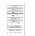
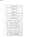
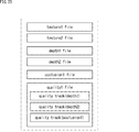
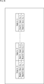
- FIG. 5 is a diagram illustrating an example of a segment file generated by the segment file generation unit 83 of FIG.
- the segment file generation unit 83 generates an 8 Mbps texture image segment file as a texture file (texture1 file), and generates a 4 Mbps texture image segment file as a texture file (texture2) file). In addition, the segment file generation unit 83 generates a 2 Mbps depth image segment file as a depth file (depth1 file), and generates a 1 Mpbs depth image segment file as a depth file (depth2 file). Further, the segment file generation unit 83 generates a segment file of 1 Mpbs occlusion image as an occlusion file (occlusion1 file).
- the segment file generation unit 83 generates a metadata segment file including quality information of 2 Mbps and 1 Mpbs depth images as a quality file (quality1 file).
- quality file quality1 file
- the metadata including the quality information of the 2Mbps depth image and the metadata including the quality information of the 1Mpbs depth image are in different tracks (quality track (depth1), quality track (depth2)). Be placed.
- the segment file generation unit 83 generates a metadata segment file including quality information of the 1 Mpbs occlusion image as a quality file (quality2 file).
- the segment file generation unit 83 separately files metadata encoded streams including quality information for each type of depth occlusion image. Therefore, when the moving image reproduction terminal 14 generates a 3D image using the texture image and the depth image, it is possible to easily obtain the desired depth image quality information from the depth image quality file (quality1 file).
- the quality information of the desired depth image is acquired from the file including the quality information of unnecessary occlusion images.
- the acquisition efficiency is poor.
- the quality information is acquired from a plurality of files when acquiring a plurality of desired depth occlusion images. Necessary and poor acquisition efficiency.
- the acquisition unit 81 does not acquire metadata including quality information of 8 Mbps and 4 Mbps texture images, but may acquire the metadata.
- the segment file generation unit 83 also generates a segment file in which an encoded stream of metadata including quality information of texture images of 8 Mbps and 4 Mbps is stored in a segment unit. Further, the metadata of the 8 Mbps texture image and the metadata of the 4 Mbps texture image are arranged in different tracks.
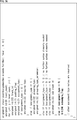
- FIG. 6 is a diagram illustrating a description example of QualityMetricsSampleEntry arranged in the quality file.
- QualityMetricsConfigurationBox is arranged in QualityMetricsSampleEntry.
- field_size_bytes and metric_count are described, and metric_code is described for metric_count.
- field_size_bytes is a data size per one kind of quality (Quality) of an encoded stream of quality information included in a quality file sample.
- Quality Quality of quality
- Metric_count is the number of quality types corresponding to the quality information encoded stream included in the quality file sample.
- the metric_code is information indicating each type of quality corresponding to the quality information encoded stream included in the quality file sample, and is described in the order of the quality information encoded stream arranged in the sample.
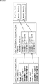
- FIG. 8 is a diagram illustrating an example of metric_code.
- metric_code not only psnr, ssim, msim, j144, j247, mops, fsig defined in ISO / IEC 23001-10 but also ocer and ocpr can be set.
- psnr indicates that the quality type indicated by the quality information is PSNR (Peak signal-to-noise ratio) of the entire screen.
- Ocer and ocpr are set when the quality information of the occlusion image is included in the sample.
- ocer represents that the quality type represented by the quality information is the ratio of the occlusion area corresponding to the occlusion image, that is, the effective range of the occlusion area, to the entire texture image screen.
- ocpr represents that the quality type represented by the quality information is a PSNR only for the occlusion image, that is, a PSNR only for the effective range of the occlusion area.
- ocer and ocpr can be set as metric_code. Therefore, quality information representing the ratio of occlusion areas and PSNR can be stored in the sample. Therefore, the video playback terminal 14 can select and play back an optimal occlusion file based on this quality information.
- the video playback terminal 14 can more appropriately occlusion based on the actual information. Allows you to select a file.
- FIG. 9 is a diagram illustrating an example of a representation element of an MPD file generated by the MPD file generation unit 84 of FIG.
- the segment file generation unit 83 includes a texture file (texture1urefile), a texture file (texture2 file), a depth file (depth1 file), a depth file (depth2 file), an occlusion file (occlusion1 file), Seven types of segment files are generated: a quality file (quality1 file (depth)) and a quality file (quality2 file (occlusion)). Accordingly, as shown in FIG. 9, the MPD file includes seven representation elements.
- FIG. 10 is a diagram illustrating a description example of the MPD file generated by the MPD file generation unit 84 of FIG.
- Reproduction pattern Reproduction of texture image of texture file (texture1 file) Reproduction pattern 2.
- Playback of texture image of texture file (texture2 file) Playback pattern 3.
- Playback of 3D image using texture file (texture1 file) and depth file (depth2 file) Playback pattern 5.
- Reproduction of 3D image using texture file (texture1 file), depth file (depth1 file), and occlusion file (reproduction pattern) 6.
- Playback of 3D image using texture file (texture1 file), depth file (depth2 file), and occlusion file (occlusion file) 3D image playback using texture file (texture2 file) and depth file (depth2 file)
- a texture file (texture1 file) group and a texture file (texture2 file) group are grouped by one adaptation set (AdaptationSet) element.
- Representation elements include Representation id, bandwidth, BaseURL, associationID.
- Representation id is an ID unique to the representation element, and is information for specifying an encoded stream corresponding to the representation element.
- bandwidth is information representing the bit rate of the texture file group
- BaseURL is information representing the base of the file name.
- associationID is Representation id of another representation element related to decoding or display (reproduction). This associationID is defined in ISO / IEC 23009-1 Amendment2.
- vt1 is described as Representation id
- 8192000 indicating 8Mbps is described as the bandwidth
- texture1.mp4 is described as the BaseURL.
- vt2 is described as Representation id, 4096000 indicating 4 Mbps is described as bandwidth, and “texture2.mp4” is described as BaseURL.
- the texture file (texture1 file) group and texture file (texture2 file) group are not related to other representation elements, the texture file (texture1 file) group and texture file (texture2 file) The association ID is not described in the representation element corresponding to the group.
- depth file (depth1depthfile) group and depth file (depth2 file) group are grouped by one adaptation set element.
- adaptation set element for the depth file a representation element corresponding to the depth file (depth1 file) group and a representation element corresponding to the depth file (depth2 file) group are described.
- vd1 is described as Representation id
- 208000 indicating 2 Mbps is described as bandwidth
- depth1.mp4 is described as BaseURL.
- the texture file group related to the display of the depth file (depth1 file) in the reproduction patterns 1 to 7 is the texture file (texture1 file) group. Accordingly, in the representation element corresponding to the depth file (depth1 file) group, vt1 that is the representation id of the texture file (texture1 file) group is described as associationID.
- vd2 is described as Representation id
- 104000 indicating 1 Mbps is described as bandwidth
- depth2.mp4 is described as BaseURL.
- the texture file group of texture images related to the display of the depth file (depth2depthfile) in the reproduction patterns 1 to 7 is a texture file (texture1 file) group or a texture file (texture2 file) group. Therefore, in the representation element corresponding to the depth file (depth1 file) group, vt1 which is the representation id of the texture file (texture1 file) group and vt2 which is the representation id of the texture file (texture2 file) group is described as associationID.
- the occlusion files are grouped by one adaptation set element.
- the adaptation set element for the occlusion file a representation element corresponding to an occlusion file group is described.
- vo1 is described as Representation id, 104000 indicating 1 Mbps is described as bandwidth, and "occlusion.mp4" is described as BaseURL.
- the depth file group of the depth image related to the display of the occlusion file (occlusion file) in the reproduction patterns 1 to 7 is a depth file (depth1 file) group or a depth file (depth2 file) group. Therefore, the representation element corresponding to the occlusion file (occlusion file) group includes vd1 as the representation ID of the depth file (depth1 file) group and vd2 as the representation file id of the depth file (depth2 file) group.
- the quality file (quality1 file) group and the quality file (quality2 file) group are grouped by one adaptation set element.
- the adaptation set element for the quality file includes a schemeIdUri for representing a combination of images to be reproduced among texture images, depth images, and occlusion images, that is, combinations of images that are candidates for use during reproduction, using SupplementalProperty.
- SchemeIdUri “urn: mpeg: dash: quality: playback: combination: 2015” can be described.
- As the value of schemeIdUri “urn: mpeg: dash: quality: playback: combination: 2015”, the Representation id of the image constituting the combination is described.
- vt1 which is the representation id of the texture file (texture1 file)
- vd1 which is the representation id of the depth file (depth1 file)
- vt1 which is the representationReid of the texture file (texture1 file)
- vd2 which is the representation id of the depth file (depth2 file)
- vt1 that is the representation id of the texture file (texture1 file)
- vd1 that is the representation id of the depth file (depth1 file)
- vt1 that is the representation id of the texture file (texture1 file)
- vd2 that is the representation id of the depth file (depth2 file)
- the MPD file describes the Representation id of the images constituting the combination of images used in the pattern to be reproduced. Therefore, the moving image reproduction terminal 14 can prevent reproduction with a pattern other than the pattern to be reproduced by referring to the MPD file and performing reproduction.
- vq1 is described as Representation ID and “quality1.mp4” is described as BaseURL.
- the quality information stored in the quality file (quality1 file) is the quality information of the depth image stored in the depth file (depth1 file) and the depth file (depth2 file). Therefore, in the representation element corresponding to the quality file (quality1 file) group, the associationID describes vd1 which is the representation id of the depth file (depth1 file) group and vd2 which is the representation id of the depth file (depth2 file) group.
- the quality information stored in the quality file (quality1qualityfile) group is the quality information of the depth image corresponding to the depth file (depth1 file) group and the depth file (depth2 file) group. Can be recognized.
- the quality information stored in any of the two tracks of the quality file is the quality of the depth image stored in the depth file (depth1 file) group or depth file (depth2 file) group. It is not possible to recognize whether it is information.
- the sub-representation element (SubRepresentation) element obtained by dividing the representation element for each level that can be associated with the track is expanded, and the sub-representation element has an associationId in the same way as the Representation element. enable. Accordingly, it is possible to describe the correspondence between each track of the quality file (quality1 file) and RepresentationID (depth related image specifying information) for specifying the depth image.
- RepresentationID depth related image specifying information
- Level 2 is associated with a track that stores the quality information of the depth image stored in the depth file (depth2 file).
- vq2 is described as Representation id and “quality2.mp4” is described as BaseURL.
- the quality information included in the metadata stored in the quality file (quality2 file) is the quality information of the occlusion image stored in the occlusion file (occlusion file). Therefore, in the representation element corresponding to the quality file (quality1 file) group, vo1 which is the representation id of the occlusion file (occlusion file) group is described as associationID.
- the bandwidth is not described in the adaptation set element for the quality file, but may be described.
- FIG. 11 is a diagram for explaining a leva box arranged in a quality file (quality1 file) when the MPD file is the MPD file of FIG.
- a leva box (Level assignment box) is arranged in a quality file (quality1 file) having a plurality of tracks.
- this leva box information specifying the track corresponding to the level is described in order from level 1, whereby the correspondence between the level and the track is described.
- the moving image playback terminal 14 can specify the track corresponding to the association ID included in the sub-representation element of the MPD file by using the leva box. Specifically, the video playback terminal 14 can specify the track corresponding to associationID as vd1 as the first track (quality track (depth1)) corresponding to level 1 from the beginning. Also, the moving image playback terminal 14 can specify the track corresponding to associationID as vd2 as the second track (quality track (depth2)) from the top corresponding to level 2.
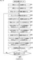
- FIG. 12 is a flowchart for explaining file generation processing of the file generation apparatus 11 of FIG.
- step S11 of FIG. 12 the acquisition unit 81 of the file generation device 11 encodes the texture data, the depth image, and the occlusion image data of the moving image content, and the encoded stream of the 2 Mbps and 1 Mbps depth images and the 1 Mbps occlusion image. Get metadata including quality information. Then, the acquisition unit 81 supplies the acquired image data and metadata to the encoding unit 82.
- step S12 the encoding unit 82 encodes the image data of the texture image supplied from the acquisition unit 81 at 8 Mbps and 4 Mbps, and encodes the image data of the depth image at 2 Mbps and 1 Mbps.
- the encoding unit 82 encodes the image data of the occlusion image at 1 Mbps.
- the encoding unit 82 encodes metadata of 2 Mbps and 1 Mbps depth images and 1 Mbps occlusion images, respectively, at a predetermined bit rate.
- the encoding unit 82 supplies the encoded stream generated as a result of the encoding to the segment file generation unit 83.
- step S13 the segment file generation unit 83 files the encoded stream of the texture image, depth image, and occlusion image supplied from the encoding unit 82 in units of segments for each bit rate.
- the segment file generation unit 83 supplies the texture file, depth file, and occlusion file generated as a result to the upload unit 85.
- step S14 the segment file generation unit 83 divides the encoded stream of metadata supplied from the encoding unit 82 into two for each type of depth occlusion image.
- step S15 the segment file generation unit 83 generates a quality file by arranging the divided encoded metadata streams in different quality files in units of segments, and supplies the quality file to the upload unit 85.
- step S16 the MPD file generation unit 84 generates an MPD file and supplies it to the upload unit 85.
- step S ⁇ b> 17 the upload unit 85 uploads the texture file, depth file, occlusion file, quality file, and MPD file to the Web server 12.
- the file generation device 11 divides the depth occlusion image quality information into different quality files by dividing the depth occlusion image quality information by type. Therefore, the number of quality files can be reduced as compared with the case where the quality information is arranged in different quality files for each depth occlusion image. Therefore, it can be said that the quality information of the depth occlusion image can be efficiently stored. In addition, it is possible to reduce the amount of processing related to the quality information acquisition of the video playback terminal 14.
- the moving image playback terminal 14 can acquire the quality information from the quality file (quality1 file) that stores only the quality information of the depth image. Therefore, the quality information acquisition efficiency can be improved as compared with the case where the quality information is acquired from the quality file storing the quality information of all the depth occlusion images.
- the file generation device 11 generates an MPD file that describes associationId in the sub-representation element.
- the MPD file can manage the correspondence relationship between each track of the quality file and the depth occlusion image in which the quality information of the plurality of depth occlusion images is divided into different tracks.
- the video playback terminal 14 can extract the quality information of each depth occlusion image from the quality file in which each of the quality information of the plurality of depth occlusion images is divided into different tracks.
- the moving image reproduction terminal 14 can only reproduce the pattern to be reproduced.
- the creator of the moving image content can provide the user with an image of the quality intended by the user.
- the video playback terminal 14 since the video playback terminal 14 only needs to select a playback pattern from the patterns to be played back, the processing load is reduced compared to the case of selecting a playback pattern from all the playback patterns that can be played back.
- FIG. 13 is a block diagram showing an example of the configuration of a streaming playback unit realized by the video playback terminal 14 of FIG. 1 executing the control software 21, the video playback software 22, and the access software 23. .
- the streaming playback unit 100 includes an MPD acquisition unit 101, an MPD processing unit 102, a quality information acquisition unit 103, a decoding unit 104, an image acquisition unit 105, a decoding unit 106, an output control unit 107, and a measurement unit 108.
- the MPD acquisition unit 101 of the streaming playback unit 100 requests and acquires the MPD file from the Web server 12.
- the MPD acquisition unit 101 supplies the acquired MPD file to the MPD processing unit 102.
- the MPD processing unit 102 analyzes the MPD file supplied from the MPD acquisition unit 101. Specifically, the MPD processing unit 102 acquires the bandwidth of each Representation element of the MPD file as the bit rate of the image corresponding to the Representation element.
- the MPD processing unit 102 selects a reproduction pattern candidate from patterns to be reproduced.
- the MPD processing unit 102 creates a list of depth occlusion image acquisition candidates based on the reproduction pattern candidates, the network bandwidth of the Internet 13 supplied from the measurement unit 108, and the image bit rate.
- the MPD processing unit 102 supplies the quality information acquisition unit 103 with the quality information acquisition information of the depth occlusion image registered in the list.
- the MPD processing unit 102 uses the quality information acquisition information of the depth image registered in the list in the quality file (quality1 file). To the quality information acquisition unit 103.
- the MPD processing unit 102 uses the quality information acquisition information of the occlusion image registered in the list in the quality file (quality2 file) The information is supplied to the information acquisition unit 103.
- the MPD processing unit 102 selects a reproduction pattern from reproduction pattern candidates based on the quality information supplied from the decoding unit 104.
- the MPD processing unit 102 supplies the image acquisition unit 105 with the texture image acquisition information of the texture file used in the reproduction of the selected reproduction pattern. Further, when a depth occlusion image file is used in the reproduction of the selected reproduction pattern, the MPD processing unit 102 supplies the acquisition information of the depth occlusion image to the image acquisition unit 105.
- the quality information acquisition unit 103 requests and acquires an encoded stream of metadata including quality information from the Web server 12 based on the acquisition information supplied from the MPD processing unit 102.
- the quality information acquisition unit 103 supplies the acquired encoded stream to the decoding unit 104.
- the decoding unit 104 decodes the encoded stream supplied from the quality information acquisition unit 103, and generates metadata including quality information.
- the decoding unit 104 supplies quality information to the MPD processing unit 102.
- the image acquisition unit 105, the decoding unit 106, and the output control unit 107 function as a reproduction unit and reproduce only the texture image or the texture image and the depth occlusion image based on the acquisition information supplied from the MPD processing unit 102. To do.
- the image acquisition unit 105 requests and acquires an encoded stream of a texture file or a depth occlusion image file from the Web server 12 based on the acquisition information supplied from the MPD processing unit 102.
- the image acquisition unit 105 supplies the acquired encoded stream to the decoding unit 104.
- the decoding unit 106 decodes the encoded stream supplied from the image acquisition unit 105 and generates image data.
- the decoding unit 106 supplies the generated image data to the output control unit 107.
- the output control unit 107 displays a display unit such as a display (not shown) included in the video playback terminal 14 based on the image data of the texture image. Display a texture image.
- the output control unit 107 outputs 3D image data based on the image data of the texture image and the depth occlusion image. Is generated.
- the output control unit 107 displays the 3D image on a display unit such as a display (not shown) based on the generated 3D image data.
- the measuring unit 108 measures the network bandwidth of the Internet 13 and supplies it to the MPD processing unit 102.
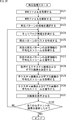
- FIG. 14 is a flowchart illustrating a first example of the playback process of the streaming playback unit 100 of FIG.
- the streaming playback unit 100 plays back a 3D image using a texture image and a depth image.
- the MPD acquisition unit 101 requests the MPD file from the Web server 12 and acquires it.
- the MPD acquisition unit 101 supplies the acquired MPD file to the MPD processing unit 102.
- step S32 the MPD processing unit 102 analyzes the MPD file supplied from the MPD acquisition unit 101. As a result, the MPD processing unit 102 acquires the bit rate of each texture image and depth image, the combination of images used for reproduction with the pattern to be reproduced, and the acquisition information of the texture image, depth image, and quality information. .
- step S33 the MPD processing unit 102 reproduces the reproduction pattern 3, which reproduces only the texture image and the depth image from the patterns to be reproduced, based on the combination of images used for reproduction with the pattern to be reproduced. 4 and 7 are selected as reproduction pattern candidates.
- the subsequent steps S34 to S43 are performed in segment units.
- step S34 the measurement unit 108 measures the network bandwidth of the Internet 13 and supplies it to the MPD processing unit 102.
- step S35 the MPD processing unit 102 determines a texture image to be acquired from the texture images used for reproduction with reproduction pattern candidates based on the network bandwidth and the bit rate of each texture image.
- the MPD processing unit 102 assumes that 80% of the network bandwidth is the maximum allowable bit rate of the texture image, and the bit rate smaller than the maximum allowable bit rate of the texture images used for reproduction with the reproduction pattern candidates. Is determined as a texture image to be acquired.
- step S36 the MPD processing unit 102 creates a list of depth image acquisition candidates based on the reproduction pattern candidates for reproducing the acquired texture image and the bit rate of the depth image.
- the MPD processing unit 102 assumes that 20% of the network bandwidth is the maximum allowable bit rate of the depth image. If the texture image to be acquired is the texture image of the texture file (texture1 file), and the bit rate of the depth image of the depth file (depth1 file) and depth file (depth2 file) is less than the maximum allowable bitrate, the MPD processing unit 102 creates a list in which depth images of depth file (depth1 file) and depth file (depth2 file) are registered based on reproduction patterns 3 and 4.
- the MPD processing unit 102 sets the reproduction pattern 7 to Based on this, a list in which depth images of depth files (depth2 file) are registered is created.
- the MPD processing unit 102 supplies the quality information acquisition unit 103 with the acquisition information of the quality information of the depth image registered in the list.
- the MPD processing unit 102 supplies the quality information acquisition unit 103 with the acquisition information of the quality information of the depth image registered in the list.
- step S37 the quality information acquisition unit 103 requests and acquires an encoded stream of metadata including the quality information of the depth image from the Web server 12 based on the acquisition information supplied from the MPD processing unit 102.
- the quality information acquisition unit 103 supplies the acquired encoded stream to the decoding unit 104.
- step S38 the decoding unit 104 decodes the encoded stream of the quality information of the depth image supplied from the quality information acquisition unit 103, and generates metadata including the quality information of the depth image.
- the decoding unit 104 supplies the depth image quality information to the MPD processing unit 102.
- step S39 the MPD processing unit 102 determines the depth image to be acquired from the depth images registered in the depth image list based on the quality information supplied from the decoding unit 104.
- the MPD processing unit 102 determines the depth image with the best quality represented by the quality information, the depth image with the quality represented by the quality information closest to the quality of the depth image of the immediately preceding segment (or subsegment), or the quality represented by the quality information. Is the acceptable quality and the depth image with the lowest bit rate is determined as the depth image to be acquired.
- the MPD processing unit 102 supplies the acquisition information of the depth image to be acquired to the image acquisition unit 105.
- step S ⁇ b> 40 the image acquisition unit 105 requests and acquires the encoded stream of the texture image and the depth image from the Web server 12 based on the acquisition information supplied from the MPD processing unit 102.
- the image acquisition unit 105 supplies the acquired encoded stream to the decoding unit 104.
- step S41 the encoded stream supplied from the image acquisition unit 105 is decoded to generate image data of a texture image and a depth image.
- the decoding unit 106 supplies the generated texture image and depth image data to the output control unit 107.
- step S42 the output control unit 107 generates 3D image data based on the texture image and the depth image image data supplied from the decoding unit 106, and displays the 3D image on a display unit (not shown).
- step S43 the streaming playback unit 100 determines whether the image of the last segment of the moving image content has been displayed. If it is determined in step S43 that the image of the last segment of the moving image content has not yet been displayed, the process returns to step S34.
- step S43 if it is determined in step S43 that the image of the last segment of the moving image content has been displayed, the process ends.
- the streaming reproduction unit 100 reproduces a 3D image using a texture image, a depth image, and an occlusion image is shown in FIG. 14 except for the following points. This is the same as the reproduction process.
- the processing for the quality information of the occlusion image is performed in the same manner as the processing of the steps S36 to S39 for the quality information of the depth image.
- the maximum allowable bit rate of the texture image, the depth image, and the occlusion image is, for example, 70%, 15%, and 15% of the network bandwidth.
- the depth image in the processing of steps S40 to S42 is both a depth image and an occlusion image.
- FIG. 15 is a flowchart for explaining a second example of the playback process of the streaming playback unit 100 of FIG.
- the streaming playback unit 100 plays back a 3D image using a texture image and a depth image.
- steps S61 to S64 in FIG. 15 are the same as the processes in steps S31 to S34 in FIG. Steps S64 to S73 are performed in units of segments.
- step S65 the MPD processing unit 102 determines the combination of the texture image and the depth image based on the reproduction pattern candidate, the network bandwidth of the Internet 13 supplied from the measurement unit 108, and the bit rate of the texture image and the depth image. Create a list of acquisition candidates.
- a lower limit of the bit rate of the texture image and the depth image may be determined in advance, and a combination in which at least one bit rate falls below the lower limit among the combinations registered in the list may be excluded.
- step S73 If the sum of the bit rates of the texture image and the depth image used for reproduction in the reproduction patterns 3, 4, and 7 exceeds the network bandwidth, the list of acquisition candidates for the combination of the texture image and the depth image is displayed. None is registered. Only the encoded stream of the texture image with the maximum bit rate not exceeding the network bandwidth is acquired, decoded, and displayed, and the process proceeds to step S73.
- step S66 the MPD processing unit 102 creates a list of depth images registered in the list created in step S65. Then, the MPD processing unit 102 supplies the quality information acquisition unit 103 with the quality information acquisition information of the depth image registered in the list.
- steps S67 and S68 is the same as the processing in steps S37 and S38 in FIG.
- step S69 the MPD processing unit 102 determines the combination of the texture image and the depth image to be acquired from the combinations registered in the list of combinations of the texture image and the depth image based on the quality information.
- the MPD processing unit 102 determines a depth image to be acquired in the same manner as in step S39 in FIG. Then, the MPD processing unit 102 determines the texture image having the highest bit rate among the texture images whose combinations with the depth image to be acquired are registered in the combination list as the texture image to be acquired.
- steps S70 to S73 Since the processing of steps S70 to S73 is the same as the processing of steps S40 to S43 in FIG.
- the second example of the reproduction process in which the streaming reproduction unit 100 reproduces the 3D image using the texture image, the depth image, and the occlusion image is shown in FIG. 15 except for the following points. This is the same as the reproduction process.
- the reproduction pattern candidates selected in step S63 in FIG. is both a depth image and an occlusion image.
- the moving image playback terminal 14 acquires the quality information of the depth occlusion image, an appropriate depth occlusion image can be acquired based on the quality information.
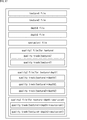
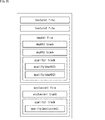
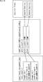
- FIG. 16 is a diagram illustrating an example of a segment file generated by the segment file generation unit 83 according to the second embodiment of the information processing system to which the present disclosure is applied.
- the segment file in FIG. 16 is the same as the segment file in FIG. 5 except for the quality file.
- the segment file generation unit 83 reproduces an encoded stream of quality information of 2 Mbps and 1 Mpbs depth image and an encoded stream of quality information of 1 Mpbs occlusion image with the encoded stream. Is divided into two for each texture image to be used. Then, the segment file generation unit 83 generates a quality file by arranging the divided encoded metadata streams in different quality files for each segment.
- the depth occlusion images used for reproduction together with the texture file (texture1 file) in reproduction with the pattern to be reproduced are 2 Mbps and 1 Mpbs depth images and 1 Mpbs occlusion images. Therefore, the segment file generation unit 83 arranges the encoded stream of metadata including quality information of 2 Mbps and 1 Mpbs depth image and the encoded stream of metadata including quality information of 1 Mpbs occlusion image in segments. Generate a quality file (quality1 file).
- each encoded stream is arranged in a different track (quality track (depth1), quality track (depth2), quality track (occlusion1)).
- the depth occlusion image used for reproduction together with the texture file (texture2 file) in reproduction with the pattern to be reproduced is a 1 Mpbs depth image.
- the segment file generating unit 83 generates a quality file (quality2 file) in which an encoded stream of metadata including quality information of a 1 Mpbs depth image is arranged in units of segments.
- the segment file generation unit 83 separately files the metadata encoded stream including quality information for each texture image. Therefore, the moving image playback terminal 14 can easily acquire the quality information of the depth occlusion image used for playback in the pattern to be played back together with the texture image by acquiring quality information from the quality file of the texture image to be acquired. Can do.
- the quality file stores only the quality information of the depth occlusion image used in the reproduction with the pattern to be reproduced together with the texture image corresponding to the quality file. Therefore, it is possible to easily obtain the quality information of the depth occlusion image to be used for reproduction together with the texture image to be obtained, as compared with the case where the encoded streams of the quality information of all the depth occlusion images are collectively filed. it can.
- the MPD file in the second embodiment is the same as the MPD file in FIG. 10 except for the following points. That is, in the MPD file in the second embodiment, the association ID included in the representation element of the quality file (quality1 file) includes not only vd1 and vd2, but also vo1.
- the representation element of the quality file (quality1 file) further includes a sub-representation element having level 3 and vo1 as associationID. Further, the association ID of the representation element of the quality file (quality2 file) is not vo1 but vd2.
- the encoded stream of metadata including quality information is divided not for the depth-related image type but for each texture image in step S14. Except for this, it is the same as the file generation process of FIG.
- the reproduction processing in the second embodiment is performed in step S36 by the MPD processing unit 102 of the texture image to be acquired from the acquisition information of the depth image quality information registered in the list.
- 14 is the same as the reproduction process of FIG. 14 except that the quality information acquisition information stored in the quality file is supplied to the quality information acquisition unit 103.
- the file generation apparatus 11 divides the quality information of the depth occlusion image for each texture image to be reproduced together with the depth occlusion image, and arranges it in different quality files. Therefore, the number of quality files can be reduced as compared with the case where the quality information is arranged in different quality files for each depth occlusion image. Therefore, it can be said that the quality information of the depth occlusion image can be efficiently stored. In addition, it is possible to reduce the amount of processing related to the quality information acquisition of the video playback terminal 14.
- the moving picture playback terminal 14 can acquire quality information from a quality file that stores only the quality information of the depth occlusion image to be played back together with the texture image to be played back. Therefore, the quality information acquisition efficiency can be improved as compared with the case where the quality information is acquired from the quality file storing the quality information of all the depth occlusion images.
- the configuration of the third embodiment of the information processing system to which the present disclosure is applied mainly includes the point that the quality information of the depth occlusion image is replaced with the quality information of the texture image or 3D image reproduced in the pattern to be reproduced, and
- the encoded information stream is the same as that of the information processing system 10 in FIG. 1 except that the encoded stream of quality information is divided for each type of reproduction pattern corresponding to the quality information and arranged in different quality files. Therefore, in the following, explanations other than those concerning the quality file will be omitted as appropriate.
- FIG. 17 is a diagram illustrating an example of a segment file generated by the segment file generation unit 83 according to the third embodiment of the information processing system to which the present disclosure is applied.
- the segment file generation unit 83 divides the encoded stream of metadata including the quality information of the reproduction patterns 1 to 7 supplied from the encoding unit 82 into three for each type of reproduction pattern. To do. Then, the segment file generation unit 83 generates a quality file by arranging the divided encoded streams in different quality files for each segment.
- the segment file generation unit 83 generates a quality file (quality1 file) in which encoded streams of reproduction pattern 1 and 2 quality information that are reproduced using only texture images are arranged in segment units.
- quality file quality1 file
- each encoded stream is arranged on a different track (quality track (texture1), quality track (texture2)).
- the segment file generation unit 83 generates a quality file (quality2 ⁇ ⁇ file) in which encoded streams of quality information of reproduction patterns 3, 4 and 7 for reproduction using only texture images and depth images are arranged in segments. To do.
- quality file quality2 file
- each encoded stream is arranged in a different track (quality track (texture1 + depth1), quality track (texture1 + depth2), quality track (texture2 + depth2)).
- the segment file generation unit 83 arranges a quality file (quality3) in which an encoded stream of metadata including quality information of the reproduction patterns 5 and 6 to be reproduced using the texture image, the depth image, and the occlusion image is arranged in units of segments. file).
- quality file quality3 file
- each encoded stream is arranged in a different track (quality track (texture1 + depth + occlusion1), quality track (texture1 + depth2 + occlusion1)).
- the segment file generation unit 83 arranges the encoded stream of metadata including the quality information of the texture image or 3D image reproduced in the pattern to be reproduced in the quality file. Therefore, the video playback terminal 14 can perform playback with high quality of the texture image or 3D image to be finally played back based on the quality information.
- the segment file generation unit 83 files the encoded stream of quality information of the pattern to be reproduced separately for each type of reproduction pattern. Therefore, the moving image playback terminal 14 can easily acquire the quality information of the playback pattern as a candidate from the quality file of the playback pattern type as a candidate.
- FIG. 18 is a diagram illustrating a description example of an MPD file according to the third embodiment.
- the description of the MPD file in FIG. 18 is the same as the description in FIG. 10 except for the adaptation set element for the quality file.
- a quality file (quality1 file) group, a quality file (quality2 file) group, and a quality file (quality3 file) group are grouped by one adaptation set element.
- vq1 is described as Representation id and “quality1.mp4” is described as BaseURL.
- the quality information stored in the quality file (quality1 file) is the quality information of the texture file (texture1 file) and texture file (texture2 file). Therefore, in the representation element corresponding to the quality file (quality1 file), vt1 and vt2 which are representation id of the texture file (texture1 file) group and the texture file (texture2 file) group are described as associationID.
- the tracks corresponding to level 1 and level 2 store the quality information of the texture file (texture1 file) and the quality information of the texture file (texture2 file), respectively.
- vq2 is described as Representation id and “quality2.mp4” is described as BaseURL.
- the quality information stored in the quality file includes 3D images, texture files (texture1 file) and depth files (depth2 file) that are played back using texture files (texture1 file) and depth files (depth1 file). ), 3D image quality information of 3D images reproduced using a texture file (texture2 ⁇ ⁇ ⁇ ⁇ file) and a depth file (depth2 file).
- the representation elements corresponding to the quality file (quality2 file) group include the representation ID of texture file (texture1 file), texture file (texture2 file), depth file (depth1 file), and depth file (depth2 file).
- the ids vt1, vt2, vd1, and vd2 are described.
- the track corresponding to level 1 stores the quality information of the 3D image reproduced using the texture file (texture1urefile) and the depth file (depth1 file).
- a track corresponding to level 2 stores quality information of a 3D image reproduced using a texture file (texture1urefile) and a depth file (depth2 file).
- a track corresponding to level 3 stores quality information of a 3D image reproduced using a texture file (texture2 file) and a depth file (depth2 file).
- the representation element corresponding to the quality file (quality2 file) group is associated with level 1 and the texture file (texture1 file) as associationID and vt1 and vd1 which are the representation id of the depth file (depth1 file)
- associationID and vt1 and vd1 which are the representation id of the depth file (depth1 file)
- associationId ”vt2 vd2
- vq3 is described as Representation id and “quality3.mp4” is described as BaseURL.
- the quality information stored in the quality file includes a 3D image reproduced using a texture file (texture1 file), a depth file (depth1 file), and an occlusion file (occlusion file), and a texture file ( This is the quality information of the 3D image reproduced using the texture1 file), depth file (depth2 file), and occlusion file (occlusion file).
- the representation element corresponding to the quality file (quality3 file) group has representationID of texture file (texture1 file), depth file (depth1 file), depth file (depth2 file), and occlusion file (occlusion file) as associationID.
- texture file texture1 file
- depth file depth1 file
- depth file depth file
- occlusion file occlusion file
- the track corresponding to level 1 stores quality information of 3D images reproduced using a texture file (texture1 file), a depth file (depth1 file), and an occlusion file (occlusion file).
- a track corresponding to level 2 stores quality information of a 3D image reproduced using a texture file (texture1urefile), a depth file (depth2 file), and an occlusion file (occlusion file).
- the representation element corresponding to the quality file (quality3 file) group includes the level 1 and the representation id of the texture file (texture1 file), depth file (depth1 file), and occlusion file (occlusion file) as associationID.
- ⁇ SubRepresentation level “1”
- associationId “vt1 vd1 vo1”> for associating a certain vt1, vd1, and vo1 is described.
- level 2 with texture file (texture1 file), depth file (depth2 file), and occlusion file (occlusion file) as vt1, vd2, and vo1 as associationID
- ⁇ SubRepresentation level ”2
- the bandwidth is not described in the adaptation set element for the quality file, but may be described.
- the quality information acquired in step S11 is the quality information of the texture image or 3D image reproduced in the pattern to be reproduced
- 12 is the same as the file generation process of FIG. 12 except that the encoded stream of metadata including quality information is divided not for the type of depth-related image but for each type of reproduction pattern in step S14.
- FIG. 19 is a flowchart for explaining a first example of the playback process of the streaming playback unit 100 according to the third embodiment.
- the streaming playback unit 100 plays back a 3D image using a texture image and a depth image.
- steps S94 to S103 are performed on a segment basis.
- step S96 the MPD processing unit 102 creates a reproduction pattern list for reproducing the acquired texture image.
- the MPD processing unit 102 assumes that 20% of the network bandwidth is the maximum allowable bit rate of the depth image. If the texture image to be acquired is the texture image of the texture file (texture1 file), and the bit rate of the depth image of the depth file (depth1 file) and depth file (depth2 file) is less than the maximum allowable bitrate, the MPD processing unit 102 creates a list in which the reproduction patterns 3 and 4 are registered.
- the MPD processing unit 102 displays Create a registered list. Then, the MPD processing unit 102 supplies the quality information acquisition unit 103 with the acquisition information of the reproduction pattern quality information registered in the list.
- step S97 the quality information acquisition unit 103 requests and acquires an encoded stream of metadata including quality information of a predetermined reproduction pattern from the Web server 12 based on the acquisition information supplied from the MPD processing unit 102. .
- the quality information acquisition unit 103 supplies the acquired encoded stream to the decoding unit 104.
- step S98 the decoding unit 104 decodes the encoded stream of the quality information of the predetermined reproduction pattern supplied from the quality information acquisition unit 103, and generates metadata including the quality information of the predetermined reproduction pattern.
- the decoding unit 104 supplies quality information of a predetermined reproduction pattern to the MPD processing unit 102.
- step S99 based on the quality information supplied from the decoding unit 104, the MPD processing unit 102 determines the depth image to be acquired from the depth images used for reproducing the reproduction patterns registered in the list.
- the MPD processing unit 102 may reproduce the reproduction pattern having the best quality represented by the quality information, the reproduction pattern closest to the reproduction pattern quality of the immediately preceding segment (or subsegment), or the quality represented by the quality information. Is the acceptable quality and the depth image used for playback with the playback pattern with the lowest bit rate is determined as the depth image to be acquired.
- the MPD processing unit 102 supplies the acquisition information of the depth image to be acquired to the image acquisition unit 105.
- steps S100 to S103 is the same as the processing of steps S40 to S43 in FIG.
- the reproduction processing in which the streaming reproduction unit 100 reproduces the 3D image using the texture image, the depth image, and the occlusion image is the same as the reproduction processing in FIG. 19 except for the following points. is there.
- the reproduction pattern candidates selected in step S93 in FIG. replaces the depth image and the occlusion image.
- the maximum allowable bit rate of the texture image, the depth image, and the occlusion image is, for example, 70%, 15%, and 15% of the network bandwidth.
- FIG. 20 is a flowchart illustrating a second example of the playback process of the streaming playback unit 100 according to the third embodiment.
- the streaming playback unit 100 plays back a 3D image using a texture image and a depth image.
- steps S121 to S124 in FIG. 20 are the same as the processes in steps S91 to S94 in FIG. 19, description thereof will be omitted.
- the processes in steps S124 to S132 are performed on a segment basis.
- step S125 the MPD processing unit 102 creates a reproduction pattern list based on the reproduction pattern candidates, the network bandwidth of the Internet 13 supplied from the measurement unit 108, and the bit rate of the texture image and the depth image.
- the lower limit of the bit rate of the texture image and the depth image is determined in advance, and among the reproduction patterns registered in the list, the reproduction pattern in which at least one of the bit rate of the texture image and the depth image used for reproduction is lower than the lower limit. May be excluded.
- steps S126 and S127 is the same as the processing in steps S97 and S98 in FIG.
- step S1208 the MPD processing unit 102, based on the quality information, from the combination of texture images and depth images used for reproduction with the reproduction patterns registered in the list, similarly to the process of S69 in FIG. The combination of the texture image and the depth image to be acquired is determined.
- steps S129 to S132 Since the processing of steps S129 to S132 is the same as the processing of steps S100 to S103 in FIG.
- the second example of the reproduction process in which the streaming reproduction unit 100 reproduces the 3D image using the texture image, the depth image, and the occlusion image is shown in FIG. 20 except for the following points. This is the same as the reproduction process.
- the reproduction pattern candidates selected in step S123 of FIG. is both a depth image and an occlusion image.
- the file generation apparatus 11 divides the quality information of the pattern to be reproduced into different quality files by dividing the information for each type of reproduction pattern. Therefore, the number of quality files can be reduced as compared with the case where quality information is arranged in different quality files for each pattern to be reproduced. Therefore, it can be said that quality information can be stored efficiently. In addition, it is possible to reduce the amount of processing related to the quality information acquisition of the video playback terminal 14.
- the video playback terminal 14 can acquire quality information from a quality file that stores only the quality information of the types of playback patterns that are candidates. Therefore, it is possible to improve the acquisition efficiency of the quality information of the reproduction pattern as a candidate as compared with the case where the quality information is acquired from the quality file storing the quality information of all the reproduction patterns.
- FIG. 21 is a diagram illustrating an example of a segment file generated by the segment file generation unit 83 according to the fourth embodiment of the information processing system to which the present disclosure is applied.
- the segment file in FIG. 21 is the same as the segment file in FIG. 5 except for the quality file.
- the segment file generation unit 83 uses texture encoded streams including the quality information of the reproduction patterns 1 to 7 supplied from the encoding unit 82 to be used for reproduction with each reproduction pattern. Divide into two for each image. Then, the segment file generation unit 83 generates a quality file by arranging the divided encoded streams in different quality files for each segment.
- the segment file generation unit 83 generates a quality file (quality1 file) in which encoded streams of quality information of reproduction patterns 1 to 5 to be reproduced using a texture file (texture1 file) are arranged in units of segments. To do.
- quality file quality1 file
- each encoded stream has a different track (quality track (texture1), quality track (texture1 + depth1), quality track (texture1 + depth2), quality track (texture1 + depth1 + occlusion), quality track (texture1 + depth2 + occlusion)).
- the segment file generation unit 83 generates a quality file (quality2 file) in which encoded streams of quality information of reproduction patterns 6 and 7 to be reproduced using a texture file (texture2 file) are arranged in units of segments.
- quality file quality2 file
- the encoded streams are arranged in different tracks (quality track (texture2), quality track (texture2 + depth2)).
- the segment file generation unit 83 separately files the encoded stream of the reproduction pattern quality information for each texture image. Therefore, the moving image playback terminal 14 can easily acquire the quality information of the pattern to be played back using the texture image by acquiring the quality information from the quality file of the acquired texture image.
- the MPD file in the fourth embodiment is the same as the MPD file in FIG. 18 except for the following points. That is, in the MPD file according to the fourth embodiment, the number of representation elements included in the quality file adaptation set element is two.
- the association IDs of the representation elements of the first quality file (quality1 file) group are vt1, vt2, vd1, vd2, and vo1.
- the representation elements of the quality file (quality1 file) are vt1 as level 1 and association ID, vt1 and vd1 as level 2 and association ID, vt1 and vd2 as level 3 and association ID, vt1, as level 4 and association ID.
- vd1, and vo1, 5 sub-representation elements each having level 5 and association IDs vt1, vd2, and vo1 are included.
- the association ID of the representation element of the second quality file is vt2 and vd2.
- the representation element of the quality file includes two sub-representation elements each having level 1 and vt2 as association ID, and level 2 and vt2 and vd2 as association ID.
- the file generation processing in the fourth embodiment is the same as that in the fourth embodiment except that the encoded stream of metadata including quality information is divided for each texture image instead of the type of reproduction pattern. This is the same as the file generation process in the third embodiment.
- reproduction process in the fourth embodiment is the same as the reproduction process of FIGS.
- the file generation apparatus 11 divides the quality information of the pattern to be reproduced for each texture image and arranges it in different quality files. Therefore, the number of quality files can be reduced as compared with the case where quality information is arranged in different quality files for each pattern to be reproduced. Therefore, it can be said that the quality information of the pattern to be reproduced can be efficiently stored. In addition, it is possible to reduce the amount of processing related to the quality information acquisition of the video playback terminal 14.
- the moving picture playback terminal 14 can acquire quality information from a quality file that stores only quality information of a pattern to be played back using a texture image to be played back. Therefore, compared with the case where quality information is acquired from a quality file that stores quality information of all reproduction patterns, the quality information acquisition efficiency of the pattern to be reproduced that is reproduced using the texture image to be reproduced is improved. Can do.
- ⁇ Fifth embodiment> (Example of segment file)
- the configuration of the fifth embodiment of the information processing system to which the present disclosure is applied is mainly that the encoded stream of metadata including quality information is divided not only for the type of reproduction pattern but also for each texture image, and has different qualities.
- the configuration is the same as that of the third embodiment except that it is arranged in a file. That is, the fifth embodiment is a combination of the third embodiment and the fourth embodiment. Therefore, in the following, explanations other than those concerning the quality file will be omitted as appropriate.
- FIG. 22 is a diagram illustrating an example of a segment file generated by the segment file generation unit 83 according to the fifth embodiment of the information processing system to which the present disclosure is applied.
- the segment file generation unit 83 converts the encoded stream of metadata including the quality information of the reproduction patterns 1 to 7 supplied from the encoding unit 82, the type of the reproduction pattern, and each reproduction pattern. Each texture image used for reproduction in is divided into five. Then, the segment file generation unit 83 generates a quality file by arranging the divided encoded streams in different quality files for each segment.
- the segment file generation unit 83 generates a quality file (quality1 file) in which an encoded stream of quality information of a reproduction pattern 1 that is reproduced using only a texture file (texture1 file) is arranged in units of segments. .
- the segment file generation unit 83 generates a quality file (quality2 file) in which encoded streams of quality information of reproduction patterns 3 and 4 that are reproduced using only a texture file (texture1 file) and a depth file are arranged in segments. Generate. In the quality file (quality2 file), each encoded stream is arranged in a different track (quality track (texture1 + depth1), quality track (texture1 + depth2)).
- the segment file generation unit 83 arranges a quality file (quality3) in which encoded streams of quality information of reproduction patterns 5 and 6 to be reproduced using a texture file (texture1 file), a depth file, and an occlusion file are arranged in units of segments. file).
- quality file quality3 file
- each encoded stream is arranged in a different track (quality track (texture1 + depth1 + occlusion), quality track (texture1 + depth2 + occlusion)).
- the segment file generation unit 83 generates a quality file (quality4 file) in which an encoded stream of quality information of the reproduction pattern 2 to be reproduced using only a texture file (texture2 file) is arranged in segments.
- the segment file generation unit 83 generates a quality file (quality5 file) in which an encoded stream of quality information of the reproduction pattern 7 that is reproduced using only the texture file (texture2 file) and the depth file is arranged in units of segments. .
- the segment file generation unit 83 separately files the encoded stream of reproduction pattern quality information for each reproduction pattern type and texture image. Therefore, the type of playback pattern to be used as a candidate, and playback using the texture image from the quality file of the pattern to be played back using the texture image to be played back. The quality information of the pattern to be obtained can be easily obtained.
- the MPD file in the fifth embodiment is the same as the MPD file in FIG. 18 except for the following points. That is, in the MPD file according to the fifth embodiment, the number of representation elements included in the quality file adaptation set element is five.
- the association ID of the representation element of the first quality file is vt1
- the associationID of the representation element of the fourth quality file is vt2.
- the association ID of the representation element of the fifth quality file is vt2 and vd2.
- the association ID of the representation element of the second quality file is vt1, vd1, and vd2.
- the representation elements of the quality file include sub-representation elements having level 1 and vt1 and vd1 as association IDs, and level 2 and vt1 and vd2 as association IDs, respectively.
- the association ID of the representation element of the third quality file (quality2 file) is vt1, vd1, vd2, and vo1.
- the representation element of the quality file (quality1 file) includes sub-representation elements having level 1 and vt1, vd1 as association ID, and vo1, level 2 and vt1, vd2, and vo1 as association ID, respectively.
- the file generation process in the fifth embodiment is performed except that the encoded stream of metadata including quality information is divided not only for the type of reproduction pattern but also for each texture image. This is the same as the file generation process in the third embodiment.
- the reproduction process in the fifth embodiment is the same as the reproduction process of FIGS.
- the file generation apparatus 11 divides the quality information of the pattern to be reproduced for each type of reproduction pattern and texture image and arranges them in different quality files. Therefore, the number of quality files can be reduced as compared with the case where quality information is arranged in different quality files for each pattern to be reproduced. Therefore, it can be said that the quality information of the pattern to be reproduced can be efficiently stored. In addition, it is possible to reduce the amount of processing related to the quality information acquisition of the video playback terminal 14.
- the video playback terminal 14 can acquire quality information from a quality file that stores only quality information of a pattern to be played back using a texture image to be played back as a candidate playback pattern type. it can. Therefore, compared to the case of acquiring quality information from a quality file that stores quality information of all reproduction patterns, the type of reproduction pattern to be reproduced using the texture image to be reproduced of the type of reproduction pattern as a candidate. The acquisition efficiency of quality information can be improved.
- FIG. 23 is a diagram illustrating an example of a segment file generated by the segment file generation unit 83 according to the sixth embodiment of the information processing system to which the present disclosure is applied.
- the segment file in FIG. 23 is the same as the segment file in FIG. 5 except for the quality file.
- the segment file generation unit 83 generates an encoded stream of metadata including quality information of 2 Mbps and 1 Mpbs depth image and an encoded stream of metadata including quality information of 1 Mpbs occlusion image. Then, one quality file (quality1 file) is generated by arranging each segment in one quality file (quality1 file).
- quality1 file different tracks (quality track (depth1), quality track (depth2), quality track (Occlusion1)) are assigned to each encoded stream.
- FIG. 24 is a diagram illustrating a description example of an MPD file according to the sixth embodiment.
- the configuration of the MPD file in FIG. 24 is the same as the configuration in FIG. 10 except for an adaptation set element for quality files.
- the quality file (quality1 file) group is grouped by one adaptation set element.
- a representation element corresponding to the quality file (quality1 file) group is described.
- vq1 is described as Representation id
- quality1.mp4 is described as the BaseURL.
- the quality information stored in the quality file (quality1 file) is the quality information of the depth file (depth1 file), depth file (depth2 file), and occlusion file (occlusion1 file). Therefore, the representation element corresponding to the quality file (quality1 file) includes the representationID of the depth file (depth1 file) group, depth file (depth2 file) group, and occlusion file (occlusion1 file) group as associationID. vd2 and vo1 are described.
- the tracks corresponding to level 1 to level 3 store the quality information of the depth file (depth1 file), the depth file (depth2 file), and the occlusion file (occlusion1 file), respectively.
- the representation element corresponding to the quality file (quality1 file) group associates level 1 with vd1 which is Representation id of the depth file (depth1 file) as associationID
- vd1 Representation level
- vd1 Representation level
- bandwidth is not described in the adaptation set element for the quality file, but may be described.
- the file generation process in the sixth embodiment is not performed in step S14, and the encoded stream of metadata including quality information is arranged in one quality file in units of segments in step S15. Except for this point, it is the same as the file generation process of FIG.
- the reproduction process in the sixth embodiment is the same as the reproduction process of FIGS.
- the combination of images in the pattern to be reproduced is described in the MPD file, but it may not be described.
- reproduction pattern candidates are selected from reproduction patterns using all combinations of images that can be combined.
- the encoded stream of quality information may be arranged in different quality files for each encoded stream.
- FIG. 25 is a diagram illustrating an example of a segment file generated by the segment file generation unit 83 according to the seventh embodiment of the information processing system to which the present disclosure is applied.
- the texture file in FIG. 25 is the same as the texture file in FIG.
- the segment file generation unit 83 generates a 2 Mbps and 1 Mpbs depth image, an encoded stream of quality information of 1 Mpbs occlusion image, a 2 Mbps and 1 Mpbs depth image, and an encoded stream of 1 Mpbs occlusion image.
- the depth occlusion image is divided into two for each type.
- the segment file generation unit 83 generates a segment file in which the encoded stream of the 2 Mbps and 1 Mpbs depth images and the encoded stream of the quality information of the 2 Mbps and 1 Mpbs depth images are arranged on a segment basis.
- the segment file generation unit 83 generates a depth file (depth1 file) in which an encoded stream of 2 Mbps and 1 Mpbs depth images and an encoded stream of quality information of 2 Mbps and 1 Mpbs depth images are arranged.
- depth file In the depth file (depth1 file), an encoded stream of 2Mbps and 1Mpbs depth image quality information is arranged on the same track (quality1 track), and an encoded stream of 2Mbps depth image and an encoded stream of 1Mpbs depth image. Are placed on different tracks (depth1 track, depth2 track).
- both the 2 Mbps and 1 Mpbs depth information of the quality information encoded stream are sampled together.
- the segment file generation unit 83 generates an occlusion file (occlusion1 ⁇ ⁇ file) in which an encoded stream of 1 Mpbs occlusion image and an encoded stream of quality information of 1 Mpbs occlusion image are arranged.
- encoded streams of quality information arranged in segment files of the same depth occlusion image are arranged in the same track. Therefore, the number of tracks in the segment file of the depth occlusion image is reduced compared to the case where the encoded stream of quality information arranged in the segment file of the same depth occlusion image is arranged in a different track for each encoded stream. can do. As a result, the size of the depth occlusion image segment file can be reduced. In addition, the load on the video playback terminal 14 can be reduced.
- FIG. 26 is a diagram illustrating a configuration example of a sample of the track (quality 1 track) in FIG.
- the track (quality 1 track) sample is divided into two subsamples, and each of the encoded streams of 2 Mbps and 1 Mpbs depth images is divided and arranged in each subsample.
- FIG. 27 is a diagram illustrating a configuration example of a moov box (movie box) of a depth file (depth1 file).
- a trak box is arranged for each track in the moov box of the depth file (depth1 file).
- a tkhd box (track header box) describing a track ID (track_ID) that is an ID unique to the track is arranged.
- the track ID of the track (depth1 track) where the encoded stream of the 2 Mbps depth image is arranged is 1, and the track of the track (depth2 ⁇ ⁇ ⁇ track) where the encoded stream of the 1 Mpbs depth image is arranged
- the ID is 2.
- the track ID of the track (quality1 track) in which the encoded stream of the quality information of the depth image of 2 Mbps and 1 Mpbs is arranged is 3.
- a tref box (track reference) describing the track ID of another track related to the own track.
- the track (quality1 track) is a track that stores an encoded stream of quality information of an encoded stream of a depth image arranged in the track (depth1 track) and the track (depth2 track).
- the track (quality11track) is provided with a tref box describing 1 and 2 which are track IDs of the track (depth1 ⁇ track) and the track (depth2 track).
- the video playback terminal 14 stores the encoded stream of the quality information of the encoded stream of the depth image in which the track (quality1 track) is arranged in the track (depth1 track) and the track (depth2 track). Can be recognized.
- the video playback terminal 14 stores the encoded stream of the quality information of the encoded stream of the depth image stored in the track (depth 1 track) or the track (depth 2 track) which subsample of the track (quality 1 track). It is not possible to recognize whether
- a correspondence relationship between a subsample and a track ID (track identification information) that identifies a track of a depth occlusion image corresponding to an encoded stream of quality information arranged in the subsample (hereinafter referred to as “track identification information”).
- track identification information a track ID that identifies a track of a depth occlusion image corresponding to an encoded stream of quality information arranged in the subsample.
- the subsample track correspondence relationship is described in QualityMetricsConfigurationBox, QualityMetricsSampleEntry, SubsampleInformationBox, or SubsampleReferenceBox in the segment file of the depth occlusion image. Also good.
- FIG. 28 is a diagram illustrating a description example of the QualityMetricsConfigurationBox when the subsample track correspondence is described in the QualityMetricsConfigurationBox arranged in the trak box of the track (quality1 track).
- field_size_bytes and metric_count are described, and metric_code is described for metric_count.
- the field_size_bytes, metric_count, and metric_count are the same as those in FIG. 6 except that the quality file is replaced with a track (quality 1 track).
- the quality file stores the encoded stream of quality information of two types of track (depth1 track) and track (depth2 track) in the sample of the track (quality1 track). Therefore, metric_count is 2.
- reference_track_in_file_flag indicating whether or not a reference track exists in the depth file (depth1 (file) including the track (quality1 track) is described in QualityMetricsConfigurationBox for each metric_code.
- the QualityMetricsConfigurationBox describes reference_track_id_num of the subsample corresponding to the metric_code and reference_track_id_num number of track_ids.
- Reference_track_id_num is the number of tracks in the reference depth file (depth1 file).
- track_id is the track ID of the track in the depth file (depth1 file) to be referenced.
- the first subsample in the sample of the track corresponds to the track (depth1 track) in the depth file (depth1 file), and the second subsample is the track Corresponds to (depth2 track).
- the reference_track_in_file_flag of metric_code corresponding to each subsample is set to 1 indicating that the reference track exists in the depth file (depth1 file) including the track (quality1 track).
- reference_track_id_num of metric_code corresponding to each subsample is 1.
- the track_id of the metric_code corresponding to the first subsample is a track ID (track identification information) that specifies the depth image track (depth1 track) corresponding to the quality information encoded stream arranged in the subsample. It is 1.
- track_id of metric_code corresponding to the second subsample is 2, which is the track ID of the track (depth2 (track) of the depth image corresponding to the encoded stream of quality information arranged in the subsample.
- the QualityMetricsConfigurationBox describes the subsample track correspondence relationship by describing the track IDs of the depth images corresponding to the subsamples in the order of arrangement in the sample.
- FIG. 29 is a diagram illustrating a description example of QualityMetricsSampleEntry when the subsample track correspondence is described in QualityMetricsSampleEntry arranged in the trak box of a track (quality1 track).
- QualityMetricsReferenceBox is arranged.
- metric_count is described similarly to the QualityMetricsConfigurationBox in FIG.
- reference_track_in_file_flag is described in the order of metric_code of QualityMetricsConfigurationBox, and when reference_track_in_file_flag of each metric_code is 1, reference_track_id_num and reference_track_id_num of track_id of the metric_code are described.
- FIG. 30 is a diagram illustrating a description example of the SubsampleInformationBox when the subsample track correspondence is described in the SubsampleInformationBox arranged in the trak box of the track (quality1 track).
- SubsampleInformationBox is a box that describes information about the subsample.
- the trak box can have a plurality of SubSampleInformationBoxes with different flags values.
- SubSampleInformationBox in FIG. 30, 2 indicating that the subsample track correspondence can be described is set as version.
- track_reference_is_exist_flag and referenced_track_in_file_flag are described for each subsample in SubsampleInformationBox.
- the track_reference_is_exist_flag is a flag indicating whether or not an extension that enables description of the subsample track correspondence relationship is necessary. As a result, when a value of 3 or more is set as version, it is possible to prevent the extension that enables the description of the subsample track correspondence relationship from being performed wastefully.
- track_reference_is_exist_flag is set to 1 indicating that extension that enables description of subsample track correspondence is necessary.
- SubsampleInformationBox describes reference_track_id_num and reference_track_id_num number of track_ids of the subsample.
- FIG. 31 is a diagram illustrating a description example of the SubsampleReferenceBox when the subsample track correspondence is described in the SubsampleReferenceBox arranged in the trak box of the track (quality1 track).
- reference_track_in_file_flag is described for each subsample.
- the reference_track_in_file_flag of each subsample is 1, track_id corresponding to the reference_track_id_num and reference_track_id_num of the subsample is described.
- FIG. 32 is a diagram illustrating a description example of an MPD file according to the seventh embodiment.
- the configuration of the MPD file of FIG. 32 is the same as that of the MPD file of FIG. 10 except that the configuration of the adaptation set element for the depth file and the adaptation set element for the occlusion file and the adaptation set element for the quality file are not provided.
- the configuration is the same.
- vd1 is described as Representation id and “depth1.mp4” is described as BaseURL.
- bandwidth is not described, but bandwidth may be described.
- the texture file to be reproduced together with the depth file (depth1 file) is a texture file (texture1 file) or a texture file (texture2 file). Therefore, in the representation element corresponding to the depth file (depth1 file), the texture file (texture1 file) and the representation id of the texture file (texture2 file) vt1 and vt2 are described as associationID.
- a track (depth 1 track) and a track (depth 2 track) are associated with each of levels 1 and 2 by the leva box.
- vo1 is described as Representation id and “occlusion1.mp4” is described as BaseURL.
- bandwidth is not described, but bandwidth may be described.
- the depth file to be played together with the occlusion file is the depth file (depth1 file). Therefore, in the representation element corresponding to the occlusion file (occlusion1 file), vd1 that is the representation id of the depth file (depth1 file) is described as associationID.
- the combination of images used in the pattern to be reproduced is not described in the MPD file, but may be described.
- the corresponding quality information is arranged in the depth file and the occlusion file generated in step S13, and the processes in steps S14 and S15 are not performed. Except for this point, it is the same as the file generation process of FIG.
- reproduction processing in the seventh embodiment is the same as the reproduction processing in FIGS. 14 and 15 except that the encoded stream is acquired with reference to the subsample track correspondence. is there.
- the file generation apparatus 11 in the seventh embodiment collectively arranges a plurality of encoded streams of quality information arranged in the same depth occlusion image segment file in one track. Therefore, the number of tracks constituting the segment file of the depth occlusion image can be reduced as compared with the case where the encoded streams of the quality information are arranged on different tracks. That is, the quality information of the depth occlusion image can be efficiently stored. Thereby, the size of the segment file of the depth occlusion image is reduced. As a result, the transmission amount when the file generation device 11 uploads the segment file of the depth occlusion image is reduced.
- the quality information is the quality information of the depth occlusion image.
- the quality information may be the quality information of the texture image or the 3D image reproduced using the texture image and the depth occlusion image. .
- a texture image track and a texture image quality information track are arranged in the texture file, and the depth file track and the quality of the 3D image reproduced using the texture image and the depth image are displayed in the depth file.
- Information tracks are arranged.
- a track of an occlusion image and a track of quality information of a 3D image reproduced using the texture image, the depth image, and the occlusion image are arranged in the occlusion file.
- FIG. 33 is a diagram illustrating an example of a segment file generated by the segment file generation unit 83 according to the eighth embodiment of the information processing system to which the present disclosure is applied.
- the segment file in FIG. 33 is the same as the segment file in FIG. 5 except for the quality file (quality1 file) of the depth image.
- the segment file generation unit 83 generates a quality file (quality1 file) in which encoded streams of quality information of 2 Mbps and 1 Mpbs depth images are collectively arranged in one track (quality1 track).
- quality1 file a quality file
- both encoded streams of quality information of depth images of 2 Mbps and 1 Mpbs are sampled together.
- the MPD file in the eighth embodiment is the same as the MPD file in FIG. That is, in the MPD file in the eighth embodiment, the correspondence between each level and the association ID that specifies the depth occlusion image is described in the representation element corresponding to the quality file (quality1 file).
- FIG. 34 is a diagram illustrating a first description example of the leva box of a quality file.
- level_count indicating the number of levels of sub-representation elements corresponding to the quality file (quality file) described in the MPD file is described in the leva box of the quality file (quality file).
- track_id, assignment_type, etc. of each level are described in order from level 1 to level_count.
- the assignment_type is the type that is associated with the level.
- 5 can be set as assignment_type.
- FIG. 35 is a diagram for explaining a first example of levels and subsamples in the quality file (quality1 file) associated with the leva box in FIG.
- the sub-representation element corresponding to the quality file (quality1 file) has two levels. Therefore, as shown in FIG. 35, 2 is described as level_count in the leva box of the quality file (quality file).
- the track corresponding to the two levels is a track with a track ID of 1 (quality 1 track). Therefore, 1 is described as two levels of track_id in the leva box of the quality file (quality file). In addition, 5 is described as assignment_type of two levels.
- the level i of each sub-representation element can be associated with the i-th metric_code described in the QualityMetricsConfigurationBox using the leva box in FIG. Then, by the description of QualityMetricsConfigurationBox, the i-th metric_code described in the QualityMetricsConfigurationBox can be associated with the i-th subsample from the top.
- 5 as assignment_type As described above, by describing 5 as the assignment_type of the leva box, the level i described in the MPD file can be associated with the i-th subsample. Therefore, 5 as assignment_type can be said to be information that associates a level with a subsample.
- FIG. 36 is a diagram illustrating a second description example of the leva box of the quality file.
- the leva box of the quality file (quality ⁇ file) in FIG. 36 is the same as the configuration in FIG. 34 except that 5 is set as assignment_type.
- 5 as the assignment_type indicates that the type of the object associated with the level is a subsample in which information is described in a subs box (Sub-Sample Information Box). That is, when the assignment_type is 5, the level i is associated with the i-th subsample from the beginning in which information is described in the subs box. In addition, in the leva box of FIG. 36, when assignment_type is 5, flags of a subs box associated with level i are described.
- FIG. 37 is a diagram illustrating a second example of levels and subsamples in the quality file (quality1 file) associated with the leva box in FIG.
- the leva box in FIG. 37 is the same as the leva box in FIG. 35 except that 0 is described as subsample_flag of each level.
- the level i of each sub-representation element can be associated with the i-th subsample from the top in which information is described in the subs box whose flags is 0, using the leva box in FIG. Then, the i-th subsample from the beginning in which information is described in the subs box can be specified by the description of the subs box.
- the level described in the MPD file can be associated with the subsample by describing 5 as the assignment_type of the leva box. Therefore, 5 as assignment_type can be said to be information that associates a level with a subsample.
- the two subsamples arranged on the track (quality 1 track) may be grouped into one group.
- the sub-sample group entry (Sub-SampleGroupEntry) shown in FIG. 38 is arranged in the trak box of the track (quality1 track).
- the subsample group entry in FIG. 38 is an extension of the SampleGroupDescriptionEntry that is the basis of the subsample group entry for subsamples that store not only images but also subsamples that store images.
- the subsample group entry in FIG. 38 describes the subsample group type (sgss in the example of FIG. 38). Also, in the subsample group entry in FIG. 38, code_parameter which is the name of the sample entry of the subsample belonging to the group and sub_sample_flags which is the flag of the subs box are described.
- the assignment_type of the leva box indicates that the type associated with the level is information on a subsample belonging to a predetermined group described in the sgpd box (sample group description box). Set to zero.
- grouping_type is the type of group of sub-subsamples corresponding to the sgpd box.
- group type to which two subsamples arranged in the track (quality1 track) belong is sgss
- the grouping_type corresponding to each level of the leva box is both sgss.
- the level i of each sub-representation element is described in the sgpd box, and the information about the i-th subsample from the top of the information about the subsample belonging to the group whose grouping_type is sgss It is associated.
- the name of the sample entry of the sample constituting the subsample and the flags of the subs box are described.
- the names of the sample entries of the samples constituting the two subsamples arranged in the track (quality1 track) are both vqme, and flags are both 0. Therefore, vqme and 0 are described in the sgpd box as information about each subsample.
- the level i of each sub-representation element is associated with the i-th subsample from the beginning in which information is described in the subs box of the sample whose flag is 0 and whose sample entry name is vqme. be able to. Then, the i-th subsample from the beginning in which information is described in the subs box can be specified by the description of the subs box.
- the level described in the MPD file can be associated with the subsample by using the leva box in FIG.
- the quality file may be divided as in the second to sixth embodiments.
- the sub-representation element is extended so that associationId can be described.
- the sub-representation element may be extended so that an attribute other than associationId can be described.
- an attribute such as SubassociationId describing RepresentationID corresponding to a subrepresentation element is newly defined, and the subrepresentation element may be extended so that the attribute can be described.
- sub-representation element is extended so that dependencyId, which is an attribute indicating the ID of the track that needs to be referred to at the time of decoding, can also be described in the sub-representation element. It may be described.
- the attribute of the sub-representation element indicating the correspondence between the sub-representation element and RepresentationID can also be used to represent a relationship other than the relationship between the texture image and the depth occlusion image or the relationship between the depth occlusion image and the quality information.
- ⁇ Ninth Embodiment> (Description of computer to which the present disclosure is applied)
- the series of processes described above can be executed by hardware or can be executed by software.
- a program constituting the software is installed in the computer.
- the computer includes, for example, a general-purpose personal computer capable of executing various functions by installing various programs by installing a computer incorporated in dedicated hardware.
- FIG. 40 is a block diagram showing an example of the hardware configuration of a computer that executes the above-described series of processing by a program.
- a CPU Central Processing Unit
- ROM Read Only Memory
- RAM Random Access Memory
- An input / output interface 205 is further connected to the bus 204.
- An input unit 206, an output unit 207, a storage unit 208, a communication unit 209, and a drive 210 are connected to the input / output interface 205.
- the input unit 206 includes a keyboard, a mouse, a microphone, and the like.
- the output unit 207 includes a display, a speaker, and the like.
- the storage unit 208 includes a hard disk, a nonvolatile memory, and the like.
- the communication unit 209 includes a network interface and the like.
- the drive 210 drives a removable medium 211 such as a magnetic disk, an optical disk, a magneto-optical disk, or a semiconductor memory.
- the CPU 201 loads the program stored in the storage unit 208 to the RAM 203 via the input / output interface 205 and the bus 204 and executes the program. A series of processing is performed.
- the program executed by the computer 200 can be provided by being recorded in, for example, a removable medium 211 such as a package medium.
- the program can be provided via a wired or wireless transmission medium such as a local area network, the Internet, or digital satellite broadcasting.
- the program can be installed in the storage unit 208 via the input / output interface 205 by attaching the removable medium 211 to the drive 210.
- the program can be received by the communication unit 209 via a wired or wireless transmission medium and installed in the storage unit 208.
- the program can be installed in the ROM 202 or the storage unit 208 in advance.
- the program executed by the computer 200 may be a program that is processed in time series in the order described in this specification, or a necessary timing such as in parallel or when a call is made. It may be a program in which processing is performed.
- the system means a set of a plurality of components (devices, modules (parts), etc.), and it does not matter whether all the components are in the same housing. Accordingly, a plurality of devices housed in separate housings and connected via a network and a single device housing a plurality of modules in one housing are all systems. .
- an occlusion image segment file may not be generated. That is, the present disclosure can be applied to an information processing system in which a depth-related image including only a depth image, or a depth-related image including both a depth image and an occlusion image, that is, a segment file of a depth-related image including at least a depth image. .
- this indication can also take the following structures.
- a file generation device comprising: a file generation unit that generates a file that divides and arranges quality information representing the quality of a depth-related image including at least a depth image.
- the file generation unit is configured to divide the quality information for each type and arrange the quality information in different files.
- the depth-related image includes an occlusion image that is a texture image of an occlusion area corresponding to the depth image.
- the quality information of the occlusion image is information representing a ratio of the occlusion area to the screen of the texture image or a noise amount of the occlusion image.
- the file generation device according to (3) or (4), wherein the type is a type of the depth-related image.
- the quality information is information representing the quality of a 3D image reproduced using the texture image corresponding to the depth-related image and the depth-related image.
- (2) or (3) File generator When the file generation unit divides the quality information of the depth-related images having a plurality of bit rates into different files by dividing the quality information, the plurality of pieces of quality information arranged in the same file are respectively stored.
- the file generation device according to any one of (2) to (7), configured to be arranged on different tracks.
- the file generation unit divides the quality information of the depth-related images having a plurality of bit rates into different files by dividing the quality information into different types, the plurality of quality information arranged in the same file are collected.
- the file generation device according to any one of (2) to (5), configured to be sampled and arranged on the same track.
- each of the plurality of quality information is divided into different subsamples, and is arranged.
- the file generation unit is configured to describe, in the file, a correspondence relationship between the subsample and track specifying information that specifies a track of the depth-related image corresponding to the quality information arranged in the subsample.
- the file generation device according to (9).
- the file generation unit is configured to describe the correspondence relationship in the file by describing track identification information of the depth-related image corresponding to the subsample in the file in the order in which the file is arranged in the sample.
- the file generation device according to (10).
- (12) The file generation device according to (10) or (11), wherein a track of the depth-related image corresponding to the quality information arranged in the subsample is arranged in the same file as the track of the quality information.
- the file generator is A file generation method comprising: a file generation step of generating a file in which quality information representing the quality of a depth-related image including at least a depth image is divided and arranged for each type.
- a playback device comprising: an acquisition unit that acquires the quality information of a predetermined type from a file in which quality information representing the quality of a depth-related image including at least a depth image is divided and arranged for each type.
- a reproduction method comprising: an acquisition step of acquiring a predetermined type of the quality information from a file in which quality information representing the quality of a depth-related image including at least a depth image is divided and arranged for each type.
- 11 file generator 11 file generator, 14 video playback terminal, 83 segment file generator, 84 MPD file generator, 103 quality information acquisition unit, 105 image acquisition unit, 106 decoding unit, 107 output control unit
Landscapes
- Engineering & Computer Science (AREA)
- Multimedia (AREA)
- Signal Processing (AREA)
- Physics & Mathematics (AREA)
- General Physics & Mathematics (AREA)
- Theoretical Computer Science (AREA)
- Library & Information Science (AREA)
- Optics & Photonics (AREA)
- Two-Way Televisions, Distribution Of Moving Picture Or The Like (AREA)
- Compression Or Coding Systems Of Tv Signals (AREA)
- Processing Or Creating Images (AREA)
- Stereoscopic And Panoramic Photography (AREA)
- Television Signal Processing For Recording (AREA)
- Testing, Inspecting, Measuring Of Stereoscopic Televisions And Televisions (AREA)
Abstract
Priority Applications (5)
| Application Number | Priority Date | Filing Date | Title |
|---|---|---|---|
| US16/064,628 US10904515B2 (en) | 2016-02-22 | 2017-02-08 | File generation apparatus and file generation method as well as reproduction apparatus and reproduction method |
| EP17756197.4A EP3422702B1 (fr) | 2016-02-22 | 2017-02-08 | Dispositif de génération de fichiers, procédé de génération de fichiers, dispositif de reproduction et procédé de reproduction |
| JP2018501553A JP6868783B2 (ja) | 2016-02-22 | 2017-02-08 | ファイル生成装置およびファイル生成方法、並びに、再生装置および再生方法 |
| CN201780011647.6A CN108702478B (zh) | 2016-02-22 | 2017-02-08 | 文件生成装置、文件生成方法、再现装置和再现方法 |
| US16/951,288 US11252397B2 (en) | 2016-02-22 | 2020-11-18 | File generation apparatus and file generation method as well as reproduction apparatus and reproduction method |
Applications Claiming Priority (2)
| Application Number | Priority Date | Filing Date | Title |
|---|---|---|---|
| JP2016030859 | 2016-02-22 | ||
| JP2016-030859 | 2016-02-22 |
Related Child Applications (2)
| Application Number | Title | Priority Date | Filing Date |
|---|---|---|---|
| US16/064,628 A-371-Of-International US10904515B2 (en) | 2016-02-22 | 2017-02-08 | File generation apparatus and file generation method as well as reproduction apparatus and reproduction method |
| US16/951,288 Continuation US11252397B2 (en) | 2016-02-22 | 2020-11-18 | File generation apparatus and file generation method as well as reproduction apparatus and reproduction method |
Publications (1)
| Publication Number | Publication Date |
|---|---|
| WO2017145756A1 true WO2017145756A1 (fr) | 2017-08-31 |
Family
ID=59685019
Family Applications (1)
| Application Number | Title | Priority Date | Filing Date |
|---|---|---|---|
| PCT/JP2017/004531 WO2017145756A1 (fr) | 2016-02-22 | 2017-02-08 | Dispositif de génération de fichiers, procédé de génération de fichiers, dispositif de reproduction et procédé de reproduction |
Country Status (5)
| Country | Link |
|---|---|
| US (2) | US10904515B2 (fr) |
| EP (1) | EP3422702B1 (fr) |
| JP (1) | JP6868783B2 (fr) |
| CN (1) | CN108702478B (fr) |
| WO (1) | WO2017145756A1 (fr) |
Cited By (2)
| Publication number | Priority date | Publication date | Assignee | Title |
|---|---|---|---|---|
| WO2021002142A1 (fr) * | 2019-07-04 | 2021-01-07 | ソニー株式会社 | Dispositif de traitement d'informations, procédé de traitement d'informations, dispositif de traitement de reproductions et procédé de traitement de reproductions |
| JP2022553964A (ja) * | 2020-06-23 | 2022-12-27 | テンセント・アメリカ・エルエルシー | ビデオ符号化の方法、装置およびコンピュータプログラム |
Families Citing this family (4)
| Publication number | Priority date | Publication date | Assignee | Title |
|---|---|---|---|---|
| US11049219B2 (en) | 2017-06-06 | 2021-06-29 | Gopro, Inc. | Methods and apparatus for multi-encoder processing of high resolution content |
| US11509917B2 (en) * | 2017-07-19 | 2022-11-22 | Nec Corporation | Data delivery device, system, method, and recording medium |
| US11228781B2 (en) | 2019-06-26 | 2022-01-18 | Gopro, Inc. | Methods and apparatus for maximizing codec bandwidth in video applications |
| US11481863B2 (en) | 2019-10-23 | 2022-10-25 | Gopro, Inc. | Methods and apparatus for hardware accelerated image processing for spherical projections |
Citations (3)
| Publication number | Priority date | Publication date | Assignee | Title |
|---|---|---|---|---|
| WO2014107377A2 (fr) * | 2013-01-04 | 2014-07-10 | Qualcomm Incorporated | Signalisation de résolution spatiale de vues de profondeur dans un format de fichier de codage multi-vue |
| WO2014112186A1 (fr) * | 2013-01-18 | 2014-07-24 | ソニー株式会社 | Serveur de contenu et procédé de distribution de contenu |
| WO2015008774A1 (fr) * | 2013-07-19 | 2015-01-22 | ソニー株式会社 | Dispositif et procédé de traitement d'informations |
Family Cites Families (12)
| Publication number | Priority date | Publication date | Assignee | Title |
|---|---|---|---|---|
| US8165447B2 (en) * | 2004-04-07 | 2012-04-24 | Panasonic Corporation | Information recording apparatus and information converting method |
| JP5542912B2 (ja) * | 2009-04-09 | 2014-07-09 | テレフオンアクチーボラゲット エル エム エリクソン(パブル) | メディア・コンテナ・ファイル管理 |
| US9406132B2 (en) * | 2010-07-16 | 2016-08-02 | Qualcomm Incorporated | Vision-based quality metric for three dimensional video |
| KR20130011994A (ko) * | 2011-07-22 | 2013-01-30 | 삼성전자주식회사 | 송신 장치, 수신 장치 및 그 송수신 방법 |
| KR20130088636A (ko) * | 2012-01-31 | 2013-08-08 | 삼성전자주식회사 | 영상 전송 장치 및 방법, 그리고 영상 재생 장치 및 방법 |
| US20130329939A1 (en) * | 2012-06-12 | 2013-12-12 | Jorg-Ulrich Mohnen | Decoding a quilted image representation into a digital asset along with content control data |
| KR102216585B1 (ko) * | 2013-01-04 | 2021-02-17 | 삼성전자주식회사 | 깊이 영상의 부호화 장치 및 복호화 장치, 부호화 방법 및 복호화 방법 |
| WO2015010056A1 (fr) * | 2013-07-19 | 2015-01-22 | Huawei Technologies Co., Ltd. | Signalisation et transport d'information de métadonnées dans la diffusion en flux adaptative sur protocole de transfert hypertexte |
| US20150181168A1 (en) * | 2013-12-20 | 2015-06-25 | DDD IP Ventures, Ltd. | Interactive quality improvement for video conferencing |
| US20170127060A1 (en) * | 2014-06-18 | 2017-05-04 | Samsung Electronics Co., Ltd. | Multi-layer video encoding method and multi-layer video decoding method using depth blocks |
| US20160373771A1 (en) * | 2015-06-18 | 2016-12-22 | Qualcomm Incorporated | Design of tracks and operation point signaling in layered hevc file format |
| KR101731430B1 (ko) * | 2015-07-02 | 2017-04-28 | 삼성전자주식회사 | 계층적 부호화 단위의 스캔 순서를 고려한 비디오 부호화 방법 및 장치, 비디오 복호화 방법 및 장치 |
-
2017
- 2017-02-08 WO PCT/JP2017/004531 patent/WO2017145756A1/fr active Application Filing
- 2017-02-08 JP JP2018501553A patent/JP6868783B2/ja active Active
- 2017-02-08 CN CN201780011647.6A patent/CN108702478B/zh active Active
- 2017-02-08 EP EP17756197.4A patent/EP3422702B1/fr active Active
- 2017-02-08 US US16/064,628 patent/US10904515B2/en active Active
-
2020
- 2020-11-18 US US16/951,288 patent/US11252397B2/en active Active
Patent Citations (3)
| Publication number | Priority date | Publication date | Assignee | Title |
|---|---|---|---|---|
| WO2014107377A2 (fr) * | 2013-01-04 | 2014-07-10 | Qualcomm Incorporated | Signalisation de résolution spatiale de vues de profondeur dans un format de fichier de codage multi-vue |
| WO2014112186A1 (fr) * | 2013-01-18 | 2014-07-24 | ソニー株式会社 | Serveur de contenu et procédé de distribution de contenu |
| WO2015008774A1 (fr) * | 2013-07-19 | 2015-01-22 | ソニー株式会社 | Dispositif et procédé de traitement d'informations |
Non-Patent Citations (1)
| Title |
|---|
| See also references of EP3422702A4 * |
Cited By (4)
| Publication number | Priority date | Publication date | Assignee | Title |
|---|---|---|---|---|
| WO2021002142A1 (fr) * | 2019-07-04 | 2021-01-07 | ソニー株式会社 | Dispositif de traitement d'informations, procédé de traitement d'informations, dispositif de traitement de reproductions et procédé de traitement de reproductions |
| US11974028B2 (en) | 2019-07-04 | 2024-04-30 | Sony Group Corporation | Information processing device, information processing method, reproduction processing device, and reproduction processing method |
| JP2022553964A (ja) * | 2020-06-23 | 2022-12-27 | テンセント・アメリカ・エルエルシー | ビデオ符号化の方法、装置およびコンピュータプログラム |
| JP7371984B2 (ja) | 2020-06-23 | 2023-10-31 | テンセント・アメリカ・エルエルシー | ビデオ符号化の方法、装置およびコンピュータプログラム |
Also Published As
| Publication number | Publication date |
|---|---|
| US20190007676A1 (en) | 2019-01-03 |
| EP3422702A1 (fr) | 2019-01-02 |
| JPWO2017145756A1 (ja) | 2018-12-20 |
| CN108702478B (zh) | 2021-07-16 |
| US11252397B2 (en) | 2022-02-15 |
| US20210076024A1 (en) | 2021-03-11 |
| US10904515B2 (en) | 2021-01-26 |
| JP6868783B2 (ja) | 2021-05-12 |
| EP3422702A4 (fr) | 2019-01-02 |
| EP3422702B1 (fr) | 2022-12-28 |
| CN108702478A (zh) | 2018-10-23 |
Similar Documents
| Publication | Publication Date | Title |
|---|---|---|
| JP6868783B2 (ja) | ファイル生成装置およびファイル生成方法、並びに、再生装置および再生方法 | |
| KR101777348B1 (ko) | 데이터 전송 방법 및 장치와 데이터 수신 방법 및 장치 | |
| WO2017145757A1 (fr) | Dispositif de génération de fichiers, procédé de génération de fichiers, dispositif de reproduction et procédé de reproduction | |
| US9277252B2 (en) | Method and apparatus for adaptive streaming based on plurality of elements for determining quality of content | |
| KR101786050B1 (ko) | 데이터 전송 방법 및 장치 | |
| WO2015182491A1 (fr) | Dispositif de traitement d'informations et procédé de traitement d'informations | |
| US9197689B2 (en) | Method and apparatus for adaptively streaming content including plurality of chapters | |
| US20110125918A1 (en) | Adaptive streaming method and apparatus | |
| JP2016007015A (ja) | 再生装置、再生装置の制御方法、生成装置、生成装置の制御方法、制御プログラム、及び該プログラムを記録した記録媒体 | |
| JP7238948B2 (ja) | 情報処理装置および情報処理方法 | |
| JP6459006B2 (ja) | 情報処理装置および情報処理方法 | |
| JPWO2016002738A1 (ja) | 情報処理装置および情報処理方法 | |
| KR101257386B1 (ko) | 통합 멀티미디어 파일 구조를 이용한 3d 멀티미디어콘텐츠 서비스 시스템 및 방법 | |
| WO2018142946A1 (fr) | Dispositif et procédé de traitement d'informations | |
| KR101944601B1 (ko) | 기간들에 걸쳐 오브젝트들을 식별하기 위한 방법 및 이에 대응하는 디바이스 | |
| JPWO2018173876A1 (ja) | コンテンツ処理装置およびコンテンツ処理方法、並びにプログラム | |
| CN101395909A (zh) | 用于组合编辑信息和媒体内容的方法和系统 |
Legal Events
| Date | Code | Title | Description |
|---|---|---|---|
| WWE | Wipo information: entry into national phase |
Ref document number: 2018501553 Country of ref document: JP |
|
| NENP | Non-entry into the national phase |
Ref country code: DE |
|
| WWE | Wipo information: entry into national phase |
Ref document number: 2017756197 Country of ref document: EP |
|
| ENP | Entry into the national phase |
Ref document number: 2017756197 Country of ref document: EP Effective date: 20180924 |
|
| 121 | Ep: the epo has been informed by wipo that ep was designated in this application |
Ref document number: 17756197 Country of ref document: EP Kind code of ref document: A1 |