WO2017145657A1 - All-solid secondary battery, method for producing all-solid secondary battery, stacked green sheet for all-solid secondary battery, stacked green sheet with current collector foil for all-solid secondary battery, and continuous stacked green sheet for all-solid secondary battery - Google Patents
All-solid secondary battery, method for producing all-solid secondary battery, stacked green sheet for all-solid secondary battery, stacked green sheet with current collector foil for all-solid secondary battery, and continuous stacked green sheet for all-solid secondary battery Download PDFInfo
- Publication number
- WO2017145657A1 WO2017145657A1 PCT/JP2017/003227 JP2017003227W WO2017145657A1 WO 2017145657 A1 WO2017145657 A1 WO 2017145657A1 JP 2017003227 W JP2017003227 W JP 2017003227W WO 2017145657 A1 WO2017145657 A1 WO 2017145657A1
- Authority
- WO
- WIPO (PCT)
- Prior art keywords
- electrode layer
- green sheet
- solid electrolyte
- negative electrode
- positive electrode
- Prior art date
Links
Images


Classifications
-
- H—ELECTRICITY
- H01—ELECTRIC ELEMENTS
- H01M—PROCESSES OR MEANS, e.g. BATTERIES, FOR THE DIRECT CONVERSION OF CHEMICAL ENERGY INTO ELECTRICAL ENERGY
- H01M4/00—Electrodes
- H01M4/02—Electrodes composed of, or comprising, active material
- H01M4/13—Electrodes for accumulators with non-aqueous electrolyte, e.g. for lithium-accumulators; Processes of manufacture thereof
-
- H—ELECTRICITY
- H01—ELECTRIC ELEMENTS
- H01M—PROCESSES OR MEANS, e.g. BATTERIES, FOR THE DIRECT CONVERSION OF CHEMICAL ENERGY INTO ELECTRICAL ENERGY
- H01M10/00—Secondary cells; Manufacture thereof
- H01M10/05—Accumulators with non-aqueous electrolyte
- H01M10/056—Accumulators with non-aqueous electrolyte characterised by the materials used as electrolytes, e.g. mixed inorganic/organic electrolytes
- H01M10/0561—Accumulators with non-aqueous electrolyte characterised by the materials used as electrolytes, e.g. mixed inorganic/organic electrolytes the electrolyte being constituted of inorganic materials only
- H01M10/0562—Solid materials
-
- H—ELECTRICITY
- H01—ELECTRIC ELEMENTS
- H01M—PROCESSES OR MEANS, e.g. BATTERIES, FOR THE DIRECT CONVERSION OF CHEMICAL ENERGY INTO ELECTRICAL ENERGY
- H01M10/00—Secondary cells; Manufacture thereof
- H01M10/05—Accumulators with non-aqueous electrolyte
- H01M10/058—Construction or manufacture
- H01M10/0585—Construction or manufacture of accumulators having only flat construction elements, i.e. flat positive electrodes, flat negative electrodes and flat separators
-
- H—ELECTRICITY
- H01—ELECTRIC ELEMENTS
- H01M—PROCESSES OR MEANS, e.g. BATTERIES, FOR THE DIRECT CONVERSION OF CHEMICAL ENERGY INTO ELECTRICAL ENERGY
- H01M4/00—Electrodes
- H01M4/02—Electrodes composed of, or comprising, active material
- H01M4/62—Selection of inactive substances as ingredients for active masses, e.g. binders, fillers
-
- Y—GENERAL TAGGING OF NEW TECHNOLOGICAL DEVELOPMENTS; GENERAL TAGGING OF CROSS-SECTIONAL TECHNOLOGIES SPANNING OVER SEVERAL SECTIONS OF THE IPC; TECHNICAL SUBJECTS COVERED BY FORMER USPC CROSS-REFERENCE ART COLLECTIONS [XRACs] AND DIGESTS
- Y02—TECHNOLOGIES OR APPLICATIONS FOR MITIGATION OR ADAPTATION AGAINST CLIMATE CHANGE
- Y02E—REDUCTION OF GREENHOUSE GAS [GHG] EMISSIONS, RELATED TO ENERGY GENERATION, TRANSMISSION OR DISTRIBUTION
- Y02E60/00—Enabling technologies; Technologies with a potential or indirect contribution to GHG emissions mitigation
- Y02E60/10—Energy storage using batteries
-
- Y—GENERAL TAGGING OF NEW TECHNOLOGICAL DEVELOPMENTS; GENERAL TAGGING OF CROSS-SECTIONAL TECHNOLOGIES SPANNING OVER SEVERAL SECTIONS OF THE IPC; TECHNICAL SUBJECTS COVERED BY FORMER USPC CROSS-REFERENCE ART COLLECTIONS [XRACs] AND DIGESTS
- Y02—TECHNOLOGIES OR APPLICATIONS FOR MITIGATION OR ADAPTATION AGAINST CLIMATE CHANGE
- Y02P—CLIMATE CHANGE MITIGATION TECHNOLOGIES IN THE PRODUCTION OR PROCESSING OF GOODS
- Y02P70/00—Climate change mitigation technologies in the production process for final industrial or consumer products
- Y02P70/50—Manufacturing or production processes characterised by the final manufactured product
Definitions
- the present invention relates to a technique for an all solid state secondary battery.
- the most promising secondary battery that satisfies these requirements is an all-solid lithium ion secondary battery in which the entire configuration of the negative electrode, the electrolyte, and the positive electrode is made of a solid material.
- This all-solid-state lithium ion secondary battery is being developed as a battery having high energy density, high safety, and long life.
- the all-solid-state lithium ion secondary battery currently in practical use is a very thin all-solid secondary battery, and its energy density is not high.
- the positive electrode layer, the solid electrolyte layer, and the negative electrode layer are produced by a vapor deposition method or a sputtering method, it is necessary to produce them under a reduced pressure atmosphere, which is not suitable for increasing the area and mass production.
- Patent Document 1 Sb 2 O 3 -doped SnO 2 and SnO 2 -doped In 2 O 3 are added as conductive assistants to the positive electrode layer and the negative electrode layer, respectively, for the purpose of improving the conductivity of the positive electrode layer and the negative electrode layer.
- Patents are disclosed.
- Patent Document 2 a positive electrode active material and a negative electrode active material coated with carbon are used for the purpose of improving the conductivity of the positive electrode layer and the negative electrode layer, and a certain amount of conductive auxiliary agent is added to the positive electrode layer and the negative electrode layer. Issued patents.
- Patent Document 1 when Sb 2 O 3 -doped SnO 2 and SnO 2 -doped In 2 O 3 are used as conductive assistants, these conductive assistants are very expensive materials, so that the positive electrode layer And there is a concern about the cost increase of the negative electrode layer.
- Patent Document 2 when a carbon-coated positive electrode active material and negative electrode active material are used for the positive electrode layer and the negative electrode layer, there are concerns about an increase in manufacturing steps and cost increase.
- the present invention has been made paying attention to the above-mentioned unsolved problems, and makes it possible to provide an all-solid-state secondary battery capable of increasing the capacity without increasing the manufacturing process and increasing the cost. The purpose is that.
- an all-solid-state secondary battery including a positive electrode layer, a solid electrolyte layer, and a negative electrode layer, the amount of carbide per unit mass contained in the positive electrode layer, the carbide per unit mass contained in the solid electrolyte layer
- the amount and amount of carbide per unit mass contained in the negative electrode layer satisfy the relationship of positive electrode layer> solid electrolyte layer and negative electrode layer> solid electrolyte layer.
- an all-solid-state secondary battery that exhibits a large capacity can be obtained.
- the all-solid-state secondary battery in one embodiment of the present invention has a configuration in which a stacked body in which a positive electrode layer, a solid electrolyte layer, and a negative electrode layer are stacked in this order is sandwiched between current collector layers from the positive electrode layer and negative electrode layer sides.
- the precursor of each of the positive electrode layer, the solid electrolyte layer, and the negative electrode layer contains a resin, and each of the precursors of the positive electrode layer, the solid electrolyte layer, and the negative electrode layer, or a laminate composed of the positive electrode layer, the solid electrolyte layer, and the negative electrode layer.
- the precursors of the positive electrode layer, the solid electrolyte layer, and the negative electrode layer are, for example, a positive electrode layer green sheet, a solid electrolyte layer green sheet, and a negative electrode layer green sheet.
- the positive electrode layer green sheet and the negative electrode layer green sheet are prepared by mixing an active material and a solid electrolyte or glass that becomes a solid electrolyte after firing and a binder made of an organic resin together with a solvent to form a positive electrode slurry and a negative electrode slurry, and these are metal current collector foils It is formed by applying or printing on a transfer PET substrate or solid electrolyte layer green sheet and then drying.
- the method for preparing the positive electrode slurry and the negative electrode slurry is not particularly limited.
- a binder having a large amount of residual carbide in the carbonization treatment is used for the positive electrode layer green sheet and the negative electrode layer green sheet.
- the solid electrolyte layer green sheet is a solid electrolyte slurry obtained by mixing a solid electrolyte or glass that becomes a solid electrolyte after firing and a binder made of an organic resin together with a solvent to form a solid electrolyte slurry, and these are positive electrode layer green sheet, negative electrode layer green sheet, or transfer It is formed by applying or printing on a PET substrate for drying and then drying.
- the method for preparing the solid electrolyte slurry is not particularly limited.
- a binder having a small amount of residual carbide in the carbonization treatment is used for the solid electrolyte layer green sheet.
- the active material in the positive electrode layer green sheet and the negative electrode layer green sheet may be any material that can occlude and release lithium ions, and is not particularly limited.
- a layer containing an active material exhibiting a noble potential is used as the positive electrode layer green sheet, and a layer containing an active material exhibiting a lower potential is used as the negative electrode layer green sheet. Can be used.
- lithium nickel cobalt manganese oxide LiNi x Co 1-y- x Mn y O 2
- lithium cobalt oxide LiCoO 2
- lithium nickel oxide LiNiO 2
- manganese Lithium phosphate LiMn 2 O 4
- lithium iron phosphate LiFePO 4
- lithium cobalt phosphate LiCoPO 4
- lithium manganese phosphate LiMnPO 4
- lithium vanadium phosphate Li 3 V 2 (PO 4 ) 3
- Examples of the active material for the negative electrode layer green sheet include carbon materials such as hard carbon, soft carbon, and graphite, alloy materials such as Sn-based alloys and Si-based alloys, nitrides such as LiCoN, and lithium titanate (Li 4 A lithium transition metal oxide such as Ti 5 O 12 ) or lithium vanadium phosphate (Li 3 V 2 (PO 4 ) 3 ) can be used. Moreover, you may use metal lithium foil.
- the positive electrode layer green sheet and the negative electrode layer green sheet may contain a conductive additive.
- the conductive auxiliary agent is not particularly limited as long as it has conductivity.
- a conductive carbon material particularly carbon black, activated carbon, carbon carbon fiber, or the like can be used.
- the content of the conductive assistant is preferably less than 90% by mass with respect to the mass of the active material. If it is 90% by mass or more, the amount of active material may be insufficient and the lithium storage capacity may be reduced.
- the solid electrolyte used for each of the positive electrode layer green sheet, the negative electrode layer green sheet, and the solid electrolyte layer green sheet is not particularly limited as long as it has a low electron conductivity and a high lithium ion conductivity.
- Amorphous bodies (glass bodies), crystalline bodies, glass ceramics, and the like of the solid electrolytes and sulfide solid electrolytes can be used.
- an oxide-based solid electrolyte that can be fired at high temperature is preferable, and NASICON type oxides, perovskite type oxides, LISICON type oxides, garnet type oxides, oxide glasses, and the like can be used .
- the solid electrolyte used for each of the positive electrode layer green sheet, the negative electrode layer green sheet, and the solid electrolyte layer green sheet may be the same or different, and two or more solid electrolytes may be used in the same green sheet. Good.
- the binder used for each of the positive electrode layer green sheet, the negative electrode layer green sheet, and the solid electrolyte layer green sheet needs to be decomposed under the firing conditions described below.
- polyvinyl alcohol, polyvinyl butyral, polyvinyl acetal, polyvinylidene fluoride, polytetra Fluoroethylene, ethyl cellulose, acrylic resin, or the like can be used.
- the binder used in the positive electrode layer green sheet and the negative electrode layer green sheet is preferably a binder having a large amount of residual carbide per unit mass, and the binder used in the solid electrolyte layer is a residual carbide per unit mass. A small amount of binder is desirable.
- the positive electrode layer green sheet and the negative electrode layer green sheet can be fired in an inert atmosphere to leave many carbides, and the solid electrolyte layer green sheet can be fired in an active atmosphere to reduce carbides.
- the binder used for each of the positive electrode layer green sheet, the negative electrode layer green sheet, and the solid electrolyte layer green sheet is preferably 3% by mass or more and 40% by mass or less.
- the binder is less than 3% by mass, sufficient binding cannot be achieved and bending resistance may be low.
- the binder is larger than 40% by mass, the battery capacity per electrode volume may be greatly reduced.
- the binder is more preferably 3% by mass or more and 25% by mass or less.
- Each of the positive electrode layer green sheet, the negative electrode layer green sheet, and the solid electrolyte layer green sheet may contain a firing aid that promotes formation of a matrix structure in each green sheet during firing and lowers the firing temperature.
- the firing aid is not particularly limited as long as it does not react with the active material and the solid electrolyte and has a softening point temperature lower than the firing temperature of the solid electrolyte.
- a boron compound can be used.
- Each of the positive electrode layer green sheet, the negative electrode layer green sheet, and the solid electrolyte layer green sheet may contain a plasticizer to improve bending resistance, and the plasticizer is not particularly limited as long as it volatilizes below the firing temperature.
- the plasticizer is not particularly limited as long as it volatilizes below the firing temperature.
- dioctyl phthalate, dibutyl phthalate, dioctyl adipate and the like can be used.
- the solvent used for each of the positive electrode slurry, the negative electrode slurry, and the solid electrolyte slurry is not particularly limited as long as the binder can be dissolved.
- alcohols such as ethanol, isopropanol, and n-butanol, toluene, ethyl acetate, butyl acetate
- organic solvents such as acetone, methyl ethyl ketone, methyl isobutyl ketone, ethylene glycol ethyl ether, isophorone, butyl lactate, dioctyl phthalate, dioctyl adipate, benzyl alcohol, N, N-dimethylformamide, N-methyl-2-pyrrolidone, and water be able to.
- these solvents may be used independently and may use 2 or more types together.
- the boiling point of the solvent is preferably 220 ° C. or lower because the slurry can be easily dried.
- the positive electrode slurry, the negative electrode slurry, and the solid electrolyte slurry can be prepared by mixing the active material, the solid electrolyte, the binder, the conductive aid, the firing aid, the solvent, and the like described above.
- the method for mixing the slurry is not particularly limited, and additives such as thickeners, plasticizers, antifoaming agents, leveling agents, and adhesion imparting agents may be added as necessary.
- the application and printing methods of the positive electrode slurry, the negative electrode slurry, and the solid electrolyte slurry include a doctor blade method, a calendar method, a spin coating method, a dip coating method, an ink jet method, an offset method, a die coating method, a spray method, and a screen.
- a printing method or the like can be used.
- the drying method of a positive electrode slurry, a negative electrode slurry, and a solid electrolyte slurry is not specifically limited, For example, heat drying, reduced pressure drying, heating reduced pressure drying, etc. can be used.
- the drying atmosphere is not particularly limited, and can be performed, for example, in an air atmosphere or an inert atmosphere (nitrogen or argon atmosphere).
- the thickness of the positive electrode layer green sheet and the negative electrode layer green sheet can be selected according to the desired battery capacity.
- the thickness of the solid electrolyte layer is preferably in the range of 1 ⁇ m to 500 ⁇ m. If it is thinner than 1 ⁇ m, the positive electrode layer and the negative electrode layer are short-circuited, and not only the performance of the all-solid-state secondary battery is lowered, but also the safety may be lowered. If it is thicker than 500 ⁇ m, the movement of conductive ions such as lithium ions in the solid electrolyte layer is hindered, and the output of the all-solid secondary battery may be lowered.
- the material of the current collector foil is not particularly limited as long as it has conductivity. For example, a metal material such as stainless steel, nickel, aluminum, iron, titanium, copper, palladium, gold, and platinum can be used. . It is preferable to select in consideration of not melting and decomposing under the firing conditions described later, or taking into consideration the battery operating potential and conductivity applied to the current collector foil.
- the all-solid-state secondary battery in one embodiment of the present invention is obtained by baking a battery constituent layer precursor containing a binder, such as a positive electrode layer green sheet, a solid electrolyte layer green sheet, and a negative electrode layer green sheet, and degreasing the binder. It is formed by stacking.
- the all-solid-state secondary battery is formed by laminating a positive electrode layer, a solid electrolyte layer, and a negative electrode layer, which are each fired body, in this order and sandwiching them with a current collector foil, or laminating a positive electrode layer, a solid electrolyte layer, and a negative electrode layer in this order.
- the firing conditions can be the same as the firing conditions in the formation of the laminated fired body.
- an all-solid secondary battery is a laminate of battery constituent layer precursors containing a binder, such as a laminate green including a positive electrode layer green sheet, a solid electrolyte layer green sheet, and a negative electrode layer green sheet. It is also formed by producing a sheet, firing, and degreasing the binder.
- the laminate green sheet may be sandwiched between current collector foils, or a current collector layer may be formed on the laminate green sheet and fired at once.
- the firing conditions can be the same as the firing conditions in the formation of the laminated fired body.
- the all-solid-state secondary battery includes a laminate of battery constituent layer precursors containing a binder on a current collector foil, such as a positive electrode layer green sheet, a solid electrolyte layer green sheet, and a negative electrode layer green. It is also formed by producing a laminate green sheet with current collector foil on which a laminate green sheet containing a sheet is formed and firing, and degreasing the binder.
- the all-solid-state secondary battery is formed by bonding the current collector foil on the positive electrode layer green sheet or the negative electrode layer green sheet farthest from the current collector foil of the laminate green sheet with current collector foil, or forming a current collector layer. It can also be produced by batch firing. The firing conditions can be the same as the firing conditions in the formation of the laminated fired body.
- the all solid state secondary battery in one embodiment of the present invention can be formed as a series all solid state secondary battery.
- a battery constituent layer precursor containing a binder for example, a positive electrode layer green sheet, a solid electrolyte layer green sheet, and a negative electrode layer green sheet are fired, and each fired body obtained by degreasing the binder is a positive electrode layer, a solid
- the electrolyte layer and the negative electrode layer are formed by sandwiching the current collector foil and continuously laminating. Or it can form by forming a current collection layer on each of the positive electrode layer and negative electrode layer which are not in contact with the solid electrolyte layer, and laminating them continuously.
- the firing conditions can be the same as the firing conditions in the formation of the laminated fired body.
- the all solid state secondary battery as the series all solid state secondary battery in one embodiment of the present invention is obtained by firing a continuous laminate green sheet obtained by continuously laminating a laminate green sheet via a current collector foil, It is also formed by degreasing.
- the all-solid-state secondary battery is formed by forming a current collecting layer on each of the positive electrode layer and the negative electrode layer that are not in contact with the solid electrolyte layer of the laminated green sheet, and firing the continuously laminated green sheet continuously laminated, It is also formed by degreasing the binder.
- the firing conditions can be the same as the firing conditions in the formation of the laminated fired body.
- the all-solid-state secondary battery as the series all-solid-state secondary battery in one embodiment of the present invention is a continuous laminate green sheet obtained by continuously laminating a laminate green sheet with current collector foil, and fired. It is also formed by degreasing the binder. Also produced by laminating the current collector foil on the cathode layer green sheet or the anode layer green sheet farthest from the current collector foil of the continuous laminate green sheet with the current collector foil or by forming the current collector layer and firing at once. can do.
- the firing conditions can be the same as the firing conditions in the formation of the laminated fired body.
- the heating temperature in the firing step is equal to or higher than the thermal decomposition temperature of the binder contained in the battery constituent layer precursor, and is lower than the oxidation temperature of the electrode active material or the combustion temperature of the current collector foil, specifically 300 degreeC or more and 1100 degrees C or less are preferable, and also 300 degreeC or more and 900 degrees C or less are preferable.
- the binder When the heating temperature is lower than 300 ° C., the binder does not completely burn and remains as a residue, which may hinder electronic conduction and ionic conduction. If the heating temperature is higher than 1100 ° C., the solid electrolyte may be melted and altered, thereby inhibiting ionic conduction.
- the atmosphere in the firing step is not particularly limited.
- the atmosphere can be performed in an air atmosphere or in an inert atmosphere (nitrogen or argon atmosphere), but the reaction between the active material and the current collector foil or the current conductivity of the current collector foil can be performed. When there is a concern about the decrease, it is desirable to carry out in an inert atmosphere.
- the time for the firing step is not particularly limited as long as the binder used is sufficiently decomposed.
- the continuous laminate green sheet used for the series all solid state secondary battery is a current collector foil of one laminate green sheet and a positive electrode layer green sheet or negative electrode of the other laminate green sheet among a plurality of laminate green sheets.
- the green sheets are laminated so as to be adjacent to each other.
- the method for laminating the laminate green sheet is not particularly limited, and for example, a flat plate press, a roll press, a hot press, a cold isostatic press, a hot isostatic press, or the like can be used.
- the all-solid-state secondary battery according to one embodiment of the present invention is the all-solid-state secondary battery including the positive electrode layer, the solid electrolyte layer, and the negative electrode layer.
- the amount of carbide per unit mass contained in the positive electrode layer, the solid electrolyte The amount of carbide per unit mass contained in the layer and the amount of carbide per unit mass contained in the negative electrode layer satisfy the relationship of positive electrode layer> solid electrolyte layer and negative electrode layer> solid electrolyte layer. Therefore, by maintaining the electron transfer resistance of the solid electrolyte layer high and the electron transfer resistance of the positive electrode layer and the negative electrode layer low, the interface between the metal current collector foil and the positive electrode layer and between the metal current collector foil and the negative electrode layer.
- An all-solid secondary battery with low resistance can be realized. Specifically, for example, by making the carbonization rate of the resin contained in each of the positive electrode layer precursor and the negative electrode layer precursor larger than the carbonization rate of the resin contained in the solid electrolyte layer precursor, all of the large capacity can be exhibited. A solid secondary battery can be realized.
- the amount of residual carbide after firing of the positive electrode layer precursor, the amount of residual carbide per unit mass after firing of the precursor of the solid electrolyte layer, and the unit after firing of the negative electrode layer precursor are set so that the amount of baked residual carbide per mass satisfies the relationship of positive electrode layer> solid electrolyte layer and negative electrode layer> solid electrolyte layer.
- the amount of carbide per unit mass contained in the positive electrode layer, the amount of carbide per unit mass contained in the solid electrolyte layer, and the amount of carbide per unit mass contained in the negative electrode layer are positive electrode layer> solid electrolyte layer, and An all-solid secondary battery that satisfies the relationship of negative electrode layer> solid electrolyte layer can be easily formed.
- the carbonization rate of the binder that is a resin contained in the precursor of the positive electrode layer the carbonization rate of the binder that is the resin contained in the precursor of the solid electrolyte layer, and the carbonization of the binder that is the resin contained in the precursor of the negative electrode layer.
- the binder is selected so that the ratio satisfies the relationship of positive electrode layer> solid electrolyte layer and negative electrode layer> solid electrolyte layer.
- the binder content can be reduced by selecting a binder with a high carbonization rate, and conversely, when a binder with a low stretch rate is used, by increasing the binder content, The amount of carbide per unit mass contained in each layer of the solid secondary battery can be easily adjusted.
- the amount of carbide per unit mass contained in the positive electrode layer is larger than the amount of carbide per unit mass contained in the solid electrolyte layer, and the amount of carbide per unit mass contained in the negative electrode layer is contained in the solid electrolyte layer. Since it can be realized by selecting a binder so that it exceeds the amount of carbide per unit mass, the capacity of all-solid-state secondary batteries can be increased without increasing the manufacturing process or increasing costs. Can do.
- pellets before firing and green sheets before firing are referred to as pellet precursors and green sheet precursors
- pellets after firing and green sheets after firing are referred to as pellet fired bodies and green sheet fired bodies. That's it.
- Example 1 Preparation of positive electrode layer pellet precursor> Lithium cobaltate LiCoO 2 (hereinafter referred to as LCO) powder 50 parts by mass as a positive electrode active material, Li 1.5 Al 0.5 Ge 1.5 (PO 4 ) 3 (hereinafter referred to as LAGP) powder as an inorganic solid electrolyte 50 parts by mass and 16 parts by mass of ethyl cellulose (manufactured by Wako Pure Chemical Industries) as a binder were mixed using a mortar. The mixture thus obtained was pressed at 1000 kgf / cm 2 using a hot press machine and formed into a cylindrical positive electrode layer pellet precursor having a diameter of 10 mm and a thickness of 1.1 mm.
- LCO Lithium cobaltate LiCoO 2
- LAGP Li 1.5 Al 0.5 Ge 1.5 (PO 4 ) 3
- ⁇ Preparation of solid electrolyte layer pellet precursor As an inorganic solid electrolyte, 100 parts by mass of LAGP powder and 16 parts by mass of polyvinyl butyral (manufactured by Kuraray) as a binder were mixed using a mortar. The mixture thus obtained was pressed at 1000 kgf / cm 2 using a hot press machine and formed into a cylindrical solid electrolyte layer pellet precursor having a diameter of 10 mm and a thickness of 1.1 mm.
- LTO Lithium titanate Li 4 Ti 5 O 12
- the positive electrode layer pellet precursor, the solid electrolyte layer pellet precursor, and the negative electrode layer pellet precursor are each heated from room temperature to 500 ° C. at a temperature increase rate of 20 ° C./min in a nitrogen stream and held at 500 ° C. for 30 minutes. Then, degreasing was performed. After degreasing, the temperature was increased from 500 ° C. to 800 ° C. at a temperature increase rate of 20 ° C./min, held at 800 ° C. for 30 minutes, and then cooled to room temperature in a furnace, and positive electrode layer pellets, solid electrolyte layer pellets, And the sintered body of each negative electrode layer pellet was obtained.
- the all-solid-state secondary battery shown in FIG. 1 was produced using the positive electrode layer pellet fired body, solid electrolyte layer pellet fired body, and negative electrode layer pellet fired body obtained as described above. Specifically, a laminate in which the positive electrode layer pellet fired body 13, the solid electrolyte layer pellet fired body 12 and the negative electrode layer pellet fired body 11 were laminated in this order was prepared. The laminate was sandwiched between two stainless steel foils as the unfired metal current collector foil 14 and pressed. That is, two stainless steel foils as unfired metal current collector foils 14 are laminated on the surface opposite to the solid electrolyte layer pellet fired body 12 in the negative electrode layer pellet fired body 11 and the positive electrode layer pellet fired body 13. The all-solid-state secondary battery was produced by pressure bonding at 1000 kgf / cm 2 using a hot press machine.
- Example 2 ⁇ Slurry production process> ⁇ Preparation of slurry for positive electrode layer green sheet> 50 parts by mass of LCO powder as a positive electrode active material, 50 parts by mass of LAGP powder as an inorganic solid electrolyte, 16 parts by mass of ethyl cellulose (manufactured by Wako Pure Chemical Industries) as a binder, 4.8 parts by mass of dibutyl phthalate (DBP) as a plasticizer, solvent 22 parts by mass of terpineol was mixed to make a slurry, and this slurry was defoamed to prepare a positive electrode layer green sheet slurry.
- LCO powder positive electrode active material
- LAGP powder as an inorganic solid electrolyte
- 16 parts by mass of ethyl cellulose manufactured by Wako Pure Chemical Industries
- DBP dibutyl phthalate
- ⁇ Preparation of slurry for negative electrode layer green sheet 50 parts by mass of LTO powder as the negative electrode active material, 50 parts by mass of LAGP powder as the inorganic solid electrolyte, 16 parts by mass of ethyl cellulose (manufactured by Wako Pure Chemical Industries) as the binder, 4.8 parts by mass of DBP as the plasticizer, and 22 parts by mass of solvent terpineol
- the slurry was defoamed to prepare a slurry for the negative electrode layer green sheet.
- ⁇ Degreasing and firing process> The positive electrode layer green sheet precursor, inorganic solid electrolyte layer green sheet precursor, and negative electrode layer green sheet precursor produced as described above were each fired by the method described in Example 1, and the positive electrode layer fired body, inorganic A solid electrolyte layer fired body and a negative electrode layer fired body were obtained.
- Example 3 ⁇ Slurry production process> In the slurry preparation step, the same operation as in Example 2 was performed. Thereby, the slurry for positive electrode layer green sheets, the slurry for inorganic solid electrolyte layer green sheets, and the slurry for negative electrode layer green sheets were produced.
- the produced positive electrode layer green sheet precursor, inorganic solid electrolyte layer green sheet precursor, and negative electrode layer green sheet precursor are laminated in this order, and are pressure-bonded at 1000 kgf / cm 2 using a hot press, and the laminate green sheet precursor is laminated.
- the body was made.
- the produced laminated green sheet precursor was fired by the method described in Example 1 to obtain a laminated fired body in which the positive electrode layer, the inorganic solid electrolyte layer, and the negative electrode layer were laminated.
- ⁇ Production process of all-solid-state secondary battery> The all-solid-state secondary battery shown in FIG. 3 was produced using the laminated fired body obtained as described above. Specifically, a laminated fired body 24 in which a positive electrode layer fired body 23, a solid electrolyte layer fired body 22 and a negative electrode layer fired body 21 are laminated in this order was prepared. Then, the laminated fired body 24 was sandwiched between two stainless steel foils as the unfired metal current collector foil 14 and pressed.
- Example 4 ⁇ Slurry production process> In the slurry preparation step, the same operation as in Example 2 was performed. This produced the positive electrode slurry, the inorganic solid electrolyte slurry, and the negative electrode slurry.
- As the positive electrode current collector foil a stainless steel foil having a thickness of 20 ⁇ m was used, and the prepared positive electrode slurry was applied onto the stainless steel foil and dried to form a positive electrode layer green sheet. On this positive electrode layer green sheet, an inorganic solid electrolyte slurry was applied and then dried to form an inorganic solid electrolyte layer green sheet.
- the negative electrode slurry is applied onto the inorganic solid electrolyte layer green sheet and dried to form a negative electrode layer green sheet.
- the negative electrode current collector foil is bonded onto the negative electrode layer green sheet, and 1000 kgf using a hot press machine. / Cm 2 was pressed to produce a laminate green sheet precursor with current collector foil.
- the all-solid-state secondary battery shown in FIG. 4 was produced using the laminated green sheet precursor with current collector foil produced as described above. Specifically, the laminate green sheet precursor with current collector foil is fired by the method described in Example 1, and the positive electrode layer fired body 23, the solid electrolyte layer fired body 22, and the negative electrode layer fired body 21 are laminated in this order. A laminated fired body 24 was prepared. The laminated fired body 24 was sandwiched between two fired bodies of stainless steel foil as the fired metal current collector foil 25. That is, in the positive electrode layer fired body 23 and the negative electrode layer fired body 21, a fired body of a stainless steel foil as the fired metal current collector foil 25 is laminated on the surface opposite to the solid electrolyte layer fired body 22, respectively. A battery was produced.
- Example 5 ⁇ Slurry production process> In the slurry preparation step, the same operation as in Example 2 was performed. This produced the positive electrode slurry, the inorganic solid electrolyte slurry, and the negative electrode slurry.
- As the positive electrode current collector foil a stainless steel foil having a thickness of 20 ⁇ m was used, and the prepared positive electrode slurry was applied onto the stainless steel foil and dried to form a positive electrode layer green sheet. On this positive electrode layer green sheet, an inorganic solid electrolyte slurry was applied and dried to form an inorganic solid electrolyte layer green sheet.
- a negative electrode slurry was applied on the inorganic solid electrolyte layer green sheet and dried to form a negative electrode layer green sheet.
- a stainless steel foil having a thickness of 20 ⁇ m is placed on the continuous laminate green sheet to form a negative electrode current collector foil, which is pressure-bonded at 1000 kgf / cm 2 using a hot press, and a continuous laminate green sheet precursor with a current collector foil is obtained.
- a serial all-solid secondary battery shown in FIG. 5 was produced using the continuous laminate green sheet precursor with current collector foil produced as described above. Specifically, the produced continuous laminated green sheet precursor with current collector foil was fired by the method described in Example 1, and the positive electrode layer fired body 23, the solid electrolyte layer fired body 22, and the negative electrode layer fired body 21 were A plurality of laminated fired bodies 24 that were sequentially laminated were prepared. The plurality of laminated fired bodies 24 are laminated in series (five in the case of FIG. 5) through a fired body of stainless steel foil as a fired metal current collector foil 25, and the positive electrode current collector foil and the negative electrode are formed at both ends. A series all-solid secondary battery was produced by sandwiching between stainless steel metal current collector foils 25 as current collector foils.
- Example 6 Example except that ethyl cellulose (manufactured by Wako Pure Chemical Industries) was used as a binder for the positive electrode layer pellet precursor and negative electrode layer pellet precursor, and an acrylic polymer (manufactured by Soken Chemical) was used as the binder for the solid electrolyte layer pellet precursor.
- the all-solid-state secondary battery was produced by the same method as 1.
- Example 7 Except for using ethyl cellulose (manufactured by Wako Pure Chemical) as a binder for the positive electrode layer green sheet precursor and negative electrode layer green sheet precursor, and using an acrylic polymer (manufactured by Soken Chemical) as the binder for the solid electrolyte layer green sheet precursor.
- An all-solid secondary battery was produced in the same manner as in Example 2.
- Example 8 Except for using ethyl cellulose (manufactured by Wako Pure Chemical) as a binder for the positive electrode layer green sheet precursor and negative electrode layer green sheet precursor, and using an acrylic polymer (manufactured by Soken Chemical) as the binder for the solid electrolyte layer green sheet precursor.
- An all-solid secondary battery was produced in the same manner as in Example 3.
- Example 9 Except for using ethyl cellulose (manufactured by Wako Pure Chemical) as a binder for the positive electrode layer green sheet precursor and negative electrode layer green sheet precursor, and using an acrylic polymer (manufactured by Soken Chemical) as the binder for the solid electrolyte layer green sheet precursor.
- An all-solid secondary battery was produced in the same manner as in Example 4. (Example 10) Except for using ethyl cellulose (manufactured by Wako Pure Chemical) as a binder for the positive electrode layer green sheet precursor and negative electrode layer green sheet precursor, and using an acrylic polymer (manufactured by Soken Chemical) as the binder for the solid electrolyte layer green sheet precursor.
- a series all-solid secondary battery was produced in the same manner as in Example 5.
- Example 3 In the same manner as in Example 3, except that ethyl cellulose (manufactured by Wako Pure Chemical Industries, Ltd.) was used as a binder for the positive electrode layer green sheet precursor, the solid electrolyte layer green sheet precursor, and the negative electrode layer green sheet precursor, A secondary battery was produced.
- Comparative Example 4 In the same manner as in Example 4, except that ethyl cellulose (manufactured by Wako Pure Chemical Industries, Ltd.) was used as a binder for the positive electrode layer green sheet precursor, the solid electrolyte layer green sheet precursor, and the negative electrode layer green sheet precursor, A secondary battery was produced.
- the battery characteristics were evaluated by the following method. Five all-solid-state secondary batteries and series all-solid-state secondary batteries shown in each example and comparative example were produced, and battery characteristics were evaluated. Specifically, the battery was charged to 2.7 V by a constant current method of 0.1 C, and then discharged to 1.5 V at 0.1 C, and the discharge amount was defined as a discharge capacity A. The discharge capacity A was an average value of five batteries. Then, it charged to 2.7V at 0.1C, discharged to 1.5V at 1C, and the discharge capacity B was calculated
- discharge capacity maintenance factor represented by ratio (discharge capacity B / discharge capacity Ax100 (%)) of the discharge capacity of discharge capacity B and discharge capacity A was calculated
- Table 3 shows the calculation results.
- a higher discharge capacity retention rate means an all-solid-state secondary battery having excellent output characteristics as a battery and a low internal resistance.
- the capacity A was 100 mAh / g or more, and the discharge capacity retention rate was 45% or more.
- the all-solid secondary batteries shown in Examples 6 to 9 using ethyl cellulose as a binder for the positive electrode layer precursor and the negative electrode layer precursor and an acrylic polymer as the binder for the solid electrolyte layer precursor also had a discharge capacity A of 100 mAh / g. As described above, the discharge capacity retention rate was 45% or more.
- the discharge capacity A of the all solid secondary batteries shown in Comparative Examples 1 to 4 in which ethyl cellulose was used as a binder for the precursor of all layers of the positive electrode layer, the solid electrolyte layer, and the negative electrode layer was less than 100 mAh / g.
- the all-solid secondary batteries shown in Comparative Examples 6 to 9 using polyvinyl butyral as a binder for the precursors of all layers of the positive electrode layer, the solid electrolyte layer, and the negative electrode layer had a discharge capacity A of 100 mAh / g or more.
- the discharge capacity B was low and was lower than the discharge capacity retention ratios of Examples 1 to 4 and 6 to 9.
- the series all-solid secondary battery also showed the same tendency as the single-layer all-solid secondary battery, and the discharge capacity A was much higher than that of Comparative Example 5 in Examples 5 and 10 and Comparative Example 10. Moreover, the discharge capacity B of Examples 5 and 10 exceeded that of Comparative Examples 5 and 10. From the above, it was confirmed that by using polyvinyl butyral or acrylic polymer having a low carbonization rate as the binder of the solid electrolyte layer precursor, the micro short-circuit between the positive electrode layer and the negative electrode layer is suppressed and a high discharge capacity A is exhibited. It was.
- ethyl cellulose having a high carbonization rate as a binder for the precursor of the positive electrode layer and the negative electrode layer, the electron conductivity of the positive electrode layer and the negative electrode layer is improved, and a high discharge capacity B and a high discharge capacity maintenance rate are achieved. It was confirmed to show.
- Negative electrode layer pellet fired body 12 Solid electrolyte layer pellet fired body 13 Positive electrode layer pellet fired body 14 Unfired metal current collector foil 21 Negative electrode layer fired body 22 Solid electrolyte layer fired body 23 Positive electrode layer fired body 24 Laminated fired body 25 Fired metal collection Electric foil
Abstract
In order to achieve an increase in the capacity of an all-solid secondary battery, the present invention provides an all-solid secondary battery that includes a stacked body obtained by stacking, in the following order, a positive electrode layer pellet sintered body (13), a solid electrolyte layer pellet sintered body (12), and a negative electrode layer pellet sintered body (11), wherein the quantity of a carbide per unit mass included in the positive electrode layer pellet sintered body (13), the quantity of the carbide per unit mass included in the solid electrolyte layer pellet sintered body (12), and the quantity of the carbide per unit mass included in the negative electrode layer pellet sintered body (11) are configured to satisfy: positive electrode layer > solid electrolyte layer; and negative electrode layer > solid electrolyte layer. This makes it possible to realize a high-capacity all-solid secondary battery in which high electron transfer resistance can be maintained in the solid electrolyte layer and low electron transfer resistance can be maintained in the positive electrode layer and the negative electrode layer, and the interface resistance between a metal current collector foil and the positive electrode layer and the metal current collector foil and the negative electrode layer is kept low.
Description
本発明は、全固体二次電池についての技術に関する。
The present invention relates to a technique for an all solid state secondary battery.
パーソナルコンピュータ、スマートフォンに代表される携帯電話、デジタルカメラ等といった電子機器の高機能化の進展に伴い、電子機器は、消費電力が増大する一方、小型化が求められている。このことから、二次電池の高エネルギー密度化が求められている。また、定置用途である家庭用蓄電池においても高エネルギー密度化が求められている。さらに、近年、ハイブリッド車や電気自動車等の車載用途の需要拡大に伴い、二次電池の高出力密度化、高エネルギー密度化の両立が求められている。この他にも、二次電池の電解液に有機溶媒が使用されているため、電解液の漏液や発火等を防止する点から、二次電池のさらなる安全性向上も求められている。
As electronic devices such as personal computers, mobile phones typified by smartphones, digital cameras, and the like have advanced in functionality, electronic devices are required to be smaller while power consumption increases. For this reason, there is a demand for higher energy density in secondary batteries. High energy density is also required for household storage batteries that are stationary applications. Further, in recent years, along with the increase in demand for in-vehicle applications such as hybrid vehicles and electric vehicles, it is required to achieve both higher output density and higher energy density of the secondary battery. In addition, since an organic solvent is used in the electrolyte solution of the secondary battery, further safety improvement of the secondary battery is required from the viewpoint of preventing leakage of the electrolyte solution, ignition, and the like.
これらの要求を満たす二次電池として最も有力であるのが、負極、電解質、及び正極の全構成が固体材料から成る全固体リチウムイオン二次電池である。この全固体リチウムイオン二次電池は、高エネルギー密度、高い安全性、及び長寿命を兼ね備えた電池として、開発が進んでいる。
しかしながら、現在実用化されている全固体リチウムイオン二次電池は、非常に薄膜な全固体二次電池であり、エネルギー密度は高くない。さらに、正極層、固体電解質層、及び負極層を、蒸着法やスパッタ法により作製しているため、減圧雰囲気下で製造する必要があり、大面積化及び大量生産には不適である。 The most promising secondary battery that satisfies these requirements is an all-solid lithium ion secondary battery in which the entire configuration of the negative electrode, the electrolyte, and the positive electrode is made of a solid material. This all-solid-state lithium ion secondary battery is being developed as a battery having high energy density, high safety, and long life.
However, the all-solid-state lithium ion secondary battery currently in practical use is a very thin all-solid secondary battery, and its energy density is not high. Furthermore, since the positive electrode layer, the solid electrolyte layer, and the negative electrode layer are produced by a vapor deposition method or a sputtering method, it is necessary to produce them under a reduced pressure atmosphere, which is not suitable for increasing the area and mass production.
そこで、正極層のグリーンシート、固体電解質層のグリーンシート及び負極層のグリーンシートを焼成することで全固体リチウムイオン二次電池を作製する手法が検討されている。また、正極層及び負極層の導電性向上が課題となっており、導電性向上を目的とした特許文献1及び特許文献2のような手法が開示されている。
例えば、特許文献1では、正極層及び負極層の導電性向上を目的として、正極層及び負極層のそれぞれにSb2O3ドープSnO2及びSnO2ドープIn2O3を導電助剤として添加した特許が開示されている。
また、特許文献2では、正極層及び負極層の導電性向上を目的として、炭素被覆した正極活物質及び負極活物質が使用され、正極層及び負極層中にも一定量の導電助剤が添加された特許が開示されている。 Therefore, a method for producing an all-solid-state lithium ion secondary battery by firing a green sheet of a positive electrode layer, a green sheet of a solid electrolyte layer, and a green sheet of a negative electrode layer has been studied. In addition, improvement in conductivity of the positive electrode layer and the negative electrode layer has been a problem, and methods such as Patent Document 1 and Patent Document 2 for improving conductivity are disclosed.
For example, in Patent Document 1, Sb 2 O 3 -doped SnO 2 and SnO 2 -doped In 2 O 3 are added as conductive assistants to the positive electrode layer and the negative electrode layer, respectively, for the purpose of improving the conductivity of the positive electrode layer and the negative electrode layer. Patents are disclosed.
In Patent Document 2, a positive electrode active material and a negative electrode active material coated with carbon are used for the purpose of improving the conductivity of the positive electrode layer and the negative electrode layer, and a certain amount of conductive auxiliary agent is added to the positive electrode layer and the negative electrode layer. Issued patents.
しかしながら、特許文献1に示すように、導電助剤としてSb2O3ドープSnO2及びSnO2ドープIn2O3を使用する場合、これら導電助剤は非常に高価な材料であるため、正極層及び負極層のコスト上昇の懸念がある。
また、特許文献2に示すように、炭素被覆した正極活物質及び負極活物質を正極層及び負極層に使用する場合、製造工程の増加やコスト上昇の懸念がある。
本発明は、上記未解決の課題に着目してなされたものであり、製造工程の増加やコスト上昇を伴うことなく、高容量化を図ることの可能な全固体二次電池を提供可能にすることを目的としている。 However, as shown in Patent Document 1, when Sb 2 O 3 -doped SnO 2 and SnO 2 -doped In 2 O 3 are used as conductive assistants, these conductive assistants are very expensive materials, so that the positive electrode layer And there is a concern about the cost increase of the negative electrode layer.
Moreover, as shown in Patent Document 2, when a carbon-coated positive electrode active material and negative electrode active material are used for the positive electrode layer and the negative electrode layer, there are concerns about an increase in manufacturing steps and cost increase.
The present invention has been made paying attention to the above-mentioned unsolved problems, and makes it possible to provide an all-solid-state secondary battery capable of increasing the capacity without increasing the manufacturing process and increasing the cost. The purpose is that.
本発明の一態様によれば、正極層、固体電解質層及び負極層を含む全固体二次電池において、正極層に含まれる単位質量当たりの炭化物量、固体電解質層に含まれる単位質量当たりの炭化物量及び負極層に含まれる単位質量当たりの炭化物量が、正極層>固体電解質層、且つ、負極層>固体電解質層の関係を満足する全固体二次電池が提供される。
According to one aspect of the present invention, in an all-solid-state secondary battery including a positive electrode layer, a solid electrolyte layer, and a negative electrode layer, the amount of carbide per unit mass contained in the positive electrode layer, the carbide per unit mass contained in the solid electrolyte layer There is provided an all-solid secondary battery in which the amount and amount of carbide per unit mass contained in the negative electrode layer satisfy the relationship of positive electrode layer> solid electrolyte layer and negative electrode layer> solid electrolyte layer.
本発明の一態様によれば、大きな容量を発揮する全固体二次電池を得ることが出来る。
According to one embodiment of the present invention, an all-solid-state secondary battery that exhibits a large capacity can be obtained.
以下に、本発明の一実施形態に係る全固体二次電池を図面を参照して説明する。
なお、本発明は、以下に記載する実施の形態に限定されうるものではなく、当業者の知識に基づいて設計の変更等の変形を加えることも可能であり、そのような変形が加えられた実施の形態も本発明の実施の形態の範囲に含まれうるものである。 Hereinafter, an all solid state secondary battery according to an embodiment of the present invention will be described with reference to the drawings.
The present invention is not limited to the embodiments described below, and modifications such as design changes can be made based on the knowledge of those skilled in the art, and such modifications have been added. Embodiments can also be included in the scope of embodiments of the present invention.
本発明の一実施形態における全固体二次電池は、正極層、固体電解質層及び負極層がこの順に積層された積層体を、正極層及び負極層側から集電層で挟み込んだ構成である。そして、正極層、固体電解質層、及び負極層それぞれの前駆体には樹脂が含まれ、正極層、固体電解質層及び負極層の各前駆体、又は正極層、固体電解質層及び負極層からなる積層体の前駆体、又は集電箔付き積層体前駆体を焼成することで、上記の樹脂の少なくとも一部が炭化して作製される。
正極層、固体電解質層及び負極層の各前駆体は、例えば正極層グリーンシート、固体電解質層グリーンシート及び負極層グリーンシートである。 The all-solid-state secondary battery in one embodiment of the present invention has a configuration in which a stacked body in which a positive electrode layer, a solid electrolyte layer, and a negative electrode layer are stacked in this order is sandwiched between current collector layers from the positive electrode layer and negative electrode layer sides. The precursor of each of the positive electrode layer, the solid electrolyte layer, and the negative electrode layer contains a resin, and each of the precursors of the positive electrode layer, the solid electrolyte layer, and the negative electrode layer, or a laminate composed of the positive electrode layer, the solid electrolyte layer, and the negative electrode layer. By firing the body precursor or the laminate precursor with current collector foil, at least a part of the resin is carbonized.
The precursors of the positive electrode layer, the solid electrolyte layer, and the negative electrode layer are, for example, a positive electrode layer green sheet, a solid electrolyte layer green sheet, and a negative electrode layer green sheet.
正極層グリーンシート及び負極層グリーンシートは、活物質と固体電解質又は焼成後に固体電解質となるガラスと有機樹脂からなるバインダーとを溶媒と共に混合して正極スラリー及び負極スラリーとし、これらを金属集電箔、転写用PET基材、又は固体電解質層グリーンシート上に塗布形成又は印刷形成した後、乾燥して形成される。正極スラリー及び負極スラリーの調製方法は特に限定されない。ここで、正極層グリーンシート及び負極層グリーンシートには、炭化処理における残存炭化物量の多いバインダーを使用する。
The positive electrode layer green sheet and the negative electrode layer green sheet are prepared by mixing an active material and a solid electrolyte or glass that becomes a solid electrolyte after firing and a binder made of an organic resin together with a solvent to form a positive electrode slurry and a negative electrode slurry, and these are metal current collector foils It is formed by applying or printing on a transfer PET substrate or solid electrolyte layer green sheet and then drying. The method for preparing the positive electrode slurry and the negative electrode slurry is not particularly limited. Here, for the positive electrode layer green sheet and the negative electrode layer green sheet, a binder having a large amount of residual carbide in the carbonization treatment is used.
固体電解質層グリーンシートは、固体電解質又は焼成後に固体電解質となるガラスと、有機樹脂からなるバインダーとを溶媒と共に混合して固体電解質スラリーとし、これらを正極層グリーンシート、負極層グリーンシート、又は転写用PET基材上に塗布形成又は印刷形成した後、乾燥して形成される。固体電解質スラリーの調製方法は特に限定されない。ここで、固体電解質層グリーンシートには、炭化処理における残存炭化物量の少ないバインダーを使用する。
正極層グリーンシート及び負極層グリーンシートにおける活物質は、リチウムイオンを吸蔵放出することができる材料であればよく、特に限定されない。正極層グリーンシート及び負極層グリーンシートのうち、より貴な電位を示す活物質を含有する層を正極層グリーンシートとして用い、より卑な電位を示す活物質を含有する層を負極層グリーンシートとして用いることができる。 The solid electrolyte layer green sheet is a solid electrolyte slurry obtained by mixing a solid electrolyte or glass that becomes a solid electrolyte after firing and a binder made of an organic resin together with a solvent to form a solid electrolyte slurry, and these are positive electrode layer green sheet, negative electrode layer green sheet, or transfer It is formed by applying or printing on a PET substrate for drying and then drying. The method for preparing the solid electrolyte slurry is not particularly limited. Here, for the solid electrolyte layer green sheet, a binder having a small amount of residual carbide in the carbonization treatment is used.
The active material in the positive electrode layer green sheet and the negative electrode layer green sheet may be any material that can occlude and release lithium ions, and is not particularly limited. Of the positive electrode layer green sheet and the negative electrode layer green sheet, a layer containing an active material exhibiting a noble potential is used as the positive electrode layer green sheet, and a layer containing an active material exhibiting a lower potential is used as the negative electrode layer green sheet. Can be used.
正極層グリーンシート用の活物質としては、例えば、ニッケルコバルトマンガン酸リチウム(LiNixCo1-y-xMnyO2)、コバルト酸リチウム(LiCoO2)、ニッケル酸リチウム(LiNiO2)、マンガン酸リチウム(LiMn2O4)、リン酸鉄リチウム(LiFePO4)、リン酸コバルトリチウム(LiCoPO4)、リン酸マンガンリチウム(LiMnPO4)、リン酸バナジウムリチウム(Li3V2(PO4)3)等のリチウム遷移金属化合物を用いることができる。
負極層グリーンシート用の活物質としては、例えば、ハードカーボン、ソフトカーボン、グラファイト等の炭素材料や、Sn系合金、Si系合金等の合金材料、LiCoN等の窒化物、チタン酸リチウム(Li4Ti5O12)、リン酸バナジウムリチウム(Li3V2(PO4)3)等のリチウム遷移金属酸化物を用いることができる。また、金属リチウム箔を用いてもよい。 As the active material for the positive electrode layer green sheets, for example, lithium nickel cobalt manganese oxide (LiNi x Co 1-y- x Mn y O 2), lithium cobalt oxide (LiCoO 2), lithium nickel oxide (LiNiO 2), manganese Lithium phosphate (LiMn 2 O 4 ), lithium iron phosphate (LiFePO 4 ), lithium cobalt phosphate (LiCoPO 4 ), lithium manganese phosphate (LiMnPO 4 ), lithium vanadium phosphate (Li 3 V 2 (PO 4 ) 3 ) And the like can be used.
Examples of the active material for the negative electrode layer green sheet include carbon materials such as hard carbon, soft carbon, and graphite, alloy materials such as Sn-based alloys and Si-based alloys, nitrides such as LiCoN, and lithium titanate (Li 4 A lithium transition metal oxide such as Ti 5 O 12 ) or lithium vanadium phosphate (Li 3 V 2 (PO 4 ) 3 ) can be used. Moreover, you may use metal lithium foil.
正極層グリーンシート及び負極層グリーンシートは、導電助剤を含有していてもよい。導電助剤としては、導電性を有するものであれば特に限定されず、例えば、導電性炭素材料、特にカーボンブラックや活性炭、カーボン炭素繊維等を用いることができる。
上記導電助剤の含有量は活物質質量に対して、90質量%未満であることが好ましい。90質量%以上であると、活物質量が不足してリチウム吸蔵容量が低下してしまうことがある。
正極層グリーンシート、負極層グリーンシート及び固体電解質層グリーンシートそれぞれに使用する固体電解質は、電子の伝導性が小さく、リチウムイオンの伝導性が高い材料であれば特に限定されず、例えば、酸化物系固体電解質や硫化物系固体電解質の非晶質体(ガラス体)、結晶体、及びガラスセラミックス等を用いることができる。特に、高温焼成が可能な酸化物系固体電解質が好ましく、NASICON型酸化物、ペロブスカイト型酸化物、LISICON型酸化物、ガーネット型酸化物、酸化物ガラス等を用いることができ、例えば、Li1.3Al0.3Ti1.7(PO4)3、Li1.5Al0.5Ge1.5(PO4)3、Li0.29La0.571TiO3、Li4SiO4-Li3PO4、Li3BO3-Li3PO4、Li7La3Zr2O12、Li3.4V0.6Si0.4O4等を用いることができる。 The positive electrode layer green sheet and the negative electrode layer green sheet may contain a conductive additive. The conductive auxiliary agent is not particularly limited as long as it has conductivity. For example, a conductive carbon material, particularly carbon black, activated carbon, carbon carbon fiber, or the like can be used.
The content of the conductive assistant is preferably less than 90% by mass with respect to the mass of the active material. If it is 90% by mass or more, the amount of active material may be insufficient and the lithium storage capacity may be reduced.
The solid electrolyte used for each of the positive electrode layer green sheet, the negative electrode layer green sheet, and the solid electrolyte layer green sheet is not particularly limited as long as it has a low electron conductivity and a high lithium ion conductivity. Amorphous bodies (glass bodies), crystalline bodies, glass ceramics, and the like of the solid electrolytes and sulfide solid electrolytes can be used. In particular, an oxide-based solid electrolyte that can be fired at high temperature is preferable, and NASICON type oxides, perovskite type oxides, LISICON type oxides, garnet type oxides, oxide glasses, and the like can be used . 3 Al 0.3 Ti 1.7 (PO 4 ) 3 , Li 1.5 Al 0.5 Ge 1.5 (PO 4 ) 3 , Li 0.29 La 0.571 TiO 3 , Li 4 SiO 4 -Li 3 PO 4, Li 3 BO 3 -Li 3 PO 4, Li 7 La 3 Zr 2O 12, Li 3.4 V 0.6 Si 0.4 O 4 and the like can be used.
上記導電助剤の含有量は活物質質量に対して、90質量%未満であることが好ましい。90質量%以上であると、活物質量が不足してリチウム吸蔵容量が低下してしまうことがある。
正極層グリーンシート、負極層グリーンシート及び固体電解質層グリーンシートそれぞれに使用する固体電解質は、電子の伝導性が小さく、リチウムイオンの伝導性が高い材料であれば特に限定されず、例えば、酸化物系固体電解質や硫化物系固体電解質の非晶質体(ガラス体)、結晶体、及びガラスセラミックス等を用いることができる。特に、高温焼成が可能な酸化物系固体電解質が好ましく、NASICON型酸化物、ペロブスカイト型酸化物、LISICON型酸化物、ガーネット型酸化物、酸化物ガラス等を用いることができ、例えば、Li1.3Al0.3Ti1.7(PO4)3、Li1.5Al0.5Ge1.5(PO4)3、Li0.29La0.571TiO3、Li4SiO4-Li3PO4、Li3BO3-Li3PO4、Li7La3Zr2O12、Li3.4V0.6Si0.4O4等を用いることができる。 The positive electrode layer green sheet and the negative electrode layer green sheet may contain a conductive additive. The conductive auxiliary agent is not particularly limited as long as it has conductivity. For example, a conductive carbon material, particularly carbon black, activated carbon, carbon carbon fiber, or the like can be used.
The content of the conductive assistant is preferably less than 90% by mass with respect to the mass of the active material. If it is 90% by mass or more, the amount of active material may be insufficient and the lithium storage capacity may be reduced.
The solid electrolyte used for each of the positive electrode layer green sheet, the negative electrode layer green sheet, and the solid electrolyte layer green sheet is not particularly limited as long as it has a low electron conductivity and a high lithium ion conductivity. Amorphous bodies (glass bodies), crystalline bodies, glass ceramics, and the like of the solid electrolytes and sulfide solid electrolytes can be used. In particular, an oxide-based solid electrolyte that can be fired at high temperature is preferable, and NASICON type oxides, perovskite type oxides, LISICON type oxides, garnet type oxides, oxide glasses, and the like can be used . 3 Al 0.3 Ti 1.7 (PO 4 ) 3 , Li 1.5 Al 0.5 Ge 1.5 (PO 4 ) 3 , Li 0.29 La 0.571 TiO 3 , Li 4 SiO 4 -Li 3 PO 4, Li 3 BO 3 -Li 3 PO 4, Li 7 La 3 Zr 2
正極層グリーンシート、負極層グリーンシート及び固体電解質層グリーンシートそれぞれに使用する固体電解質は、同じであっても異なってもよく、同一のグリーンシート内に2種以上の固体電解質を併用してもよい。
正極層グリーンシート、負極層グリーンシート及び固体電解質層グリーンシートそれぞれに使用するバインダーは、後述する焼成条件で分解する必要があり、例えば、ポリビニルアルコール、ポリビニルブチラール、ポリビニルアセタール、ポリフッ化ビニリデン、ポリテトラフルオロエチレン、エチルセルロース、アクリル樹脂等を用いることができる。 The solid electrolyte used for each of the positive electrode layer green sheet, the negative electrode layer green sheet, and the solid electrolyte layer green sheet may be the same or different, and two or more solid electrolytes may be used in the same green sheet. Good.
The binder used for each of the positive electrode layer green sheet, the negative electrode layer green sheet, and the solid electrolyte layer green sheet needs to be decomposed under the firing conditions described below. For example, polyvinyl alcohol, polyvinyl butyral, polyvinyl acetal, polyvinylidene fluoride, polytetra Fluoroethylene, ethyl cellulose, acrylic resin, or the like can be used.
さらに、正極層グリーンシート及び負極層グリーンシートに使用するバインダーとしては、単位質量当たりの残存炭化物量が多いバインダーであることが望ましく、固体電解質層に使用するバインダーとしては、単位質量当たりの残存炭化物量が少ないバインダーであることが望ましい。正極層グリーンシート及び負極層グリーンシートは不活性雰囲気下で焼成して多くの炭化物を残存させ、固体電解質層グリーンシートは活性雰囲気下で焼成して炭化物を低減させることも可能である。
正極層グリーンシート、負極層グリーンシート及び固体電解質層グリーンシートそれぞれに使用するバインダーは、3質量%以上40質量%以下であることが望ましい。バインダーが3質量%より少ない場合、十分な結着をすることができず屈曲耐性が低い可能性がある。バインダーが、40質量%より大きい場合には、電極体積当たりの電池容量が大きく低下する可能性がある。バインダーは、より好ましくは3質量%以上25質量%以下である。 Furthermore, the binder used in the positive electrode layer green sheet and the negative electrode layer green sheet is preferably a binder having a large amount of residual carbide per unit mass, and the binder used in the solid electrolyte layer is a residual carbide per unit mass. A small amount of binder is desirable. The positive electrode layer green sheet and the negative electrode layer green sheet can be fired in an inert atmosphere to leave many carbides, and the solid electrolyte layer green sheet can be fired in an active atmosphere to reduce carbides.
The binder used for each of the positive electrode layer green sheet, the negative electrode layer green sheet, and the solid electrolyte layer green sheet is preferably 3% by mass or more and 40% by mass or less. If the binder is less than 3% by mass, sufficient binding cannot be achieved and bending resistance may be low. When the binder is larger than 40% by mass, the battery capacity per electrode volume may be greatly reduced. The binder is more preferably 3% by mass or more and 25% by mass or less.
正極層グリーンシート、負極層グリーンシート及び固体電解質層グリーンシートそれぞれは、焼成時に各グリーンシート内におけるマトリックス構造の形成を促進し、焼成温度を低下させる焼成助剤を含有していてもよい。焼成助剤は活物質及び固体電解質と反応せず、固体電解質の焼成温度よりも軟化点温度が低ければ特に限定はされず、例えばホウ素化合物を用いることができる。各グリーンシートの焼成助剤の含有量と焼成温度を調整することで、積層焼成体を焼成により形成する際に、各層の内部歪や内部応力によるクラックを防止すると共に、マトリックス構造の形成を促進することができる。
Each of the positive electrode layer green sheet, the negative electrode layer green sheet, and the solid electrolyte layer green sheet may contain a firing aid that promotes formation of a matrix structure in each green sheet during firing and lowers the firing temperature. The firing aid is not particularly limited as long as it does not react with the active material and the solid electrolyte and has a softening point temperature lower than the firing temperature of the solid electrolyte. For example, a boron compound can be used. By adjusting the content and firing temperature of the firing aid of each green sheet, when forming a laminated fired body by firing, it prevents cracking due to internal strain and internal stress of each layer and promotes the formation of a matrix structure can do.
正極層グリーンシート、負極層グリーンシート及び固体電解質層グリーンシートそれぞれは、屈曲耐性を向上させるために可塑剤を含有してもよく、可塑剤としては焼成温度以下で揮発すれば特には限定されず、例えばフタル酸ジオクチル、フタル酸ジブチル、アジピン酸ジオクチル等を用いることができる。
正極スラリー、負極スラリー及び固体電解質スラリーそれぞれに用いる溶媒は、上記バインダーを溶解可能であれば特に限定されず、例えば、エタノール、イソプロパノール、n-ブタノール等のアルコール類、トルエン、酢酸エチル、酢酸ブチル、アセトン、メチルエチルケトン、メチルイソブチルケトン、エチレングリコールエチルエーテル、イソホロン、乳酸ブチル、ジオクチルフタレート、ジオクチルアジペート、ベンジルアルコール、N,N-ジメチルホルムアミド、N-メチル-2-ピロリドン等の有機溶剤、及び水を用いることができる。なお、これらの溶媒は単独で用いてもよく、2種以上を併用してもよい。スラリーの乾燥が容易であることから、溶媒の沸点は220℃以下であることが好ましい。 Each of the positive electrode layer green sheet, the negative electrode layer green sheet, and the solid electrolyte layer green sheet may contain a plasticizer to improve bending resistance, and the plasticizer is not particularly limited as long as it volatilizes below the firing temperature. For example, dioctyl phthalate, dibutyl phthalate, dioctyl adipate and the like can be used.
The solvent used for each of the positive electrode slurry, the negative electrode slurry, and the solid electrolyte slurry is not particularly limited as long as the binder can be dissolved. For example, alcohols such as ethanol, isopropanol, and n-butanol, toluene, ethyl acetate, butyl acetate, Use organic solvents such as acetone, methyl ethyl ketone, methyl isobutyl ketone, ethylene glycol ethyl ether, isophorone, butyl lactate, dioctyl phthalate, dioctyl adipate, benzyl alcohol, N, N-dimethylformamide, N-methyl-2-pyrrolidone, and water be able to. In addition, these solvents may be used independently and may use 2 or more types together. The boiling point of the solvent is preferably 220 ° C. or lower because the slurry can be easily dried.
正極スラリー、負極スラリー及び固体電解質スラリーは、上述した活物質、固体電解質、バインダー、導電助剤、焼成助剤、溶媒等を混合することで作製できる。スラリーの混合方法は特に限定されず、必要に応じて、増粘剤、可塑剤、消泡剤、レベリング剤、密着性付与剤のような添加剤を添加してもよい。
正極スラリー、負極スラリー及び固体電解質スラリーの塗布及び印刷方法としては、具体的には、ドクターブレード法、カレンダー法、スピンコート法、ディップコート法、インクジェット法、オフセット法、ダイコート法、スプレー法、スクリーン印刷法等を用いることができる。 The positive electrode slurry, the negative electrode slurry, and the solid electrolyte slurry can be prepared by mixing the active material, the solid electrolyte, the binder, the conductive aid, the firing aid, the solvent, and the like described above. The method for mixing the slurry is not particularly limited, and additives such as thickeners, plasticizers, antifoaming agents, leveling agents, and adhesion imparting agents may be added as necessary.
Specifically, the application and printing methods of the positive electrode slurry, the negative electrode slurry, and the solid electrolyte slurry include a doctor blade method, a calendar method, a spin coating method, a dip coating method, an ink jet method, an offset method, a die coating method, a spray method, and a screen. A printing method or the like can be used.
正極スラリー、負極スラリー及び固体電解質スラリーの乾燥方法は、特に限定されず、例えば、加熱乾燥、減圧乾燥、加熱減圧乾燥等を用いることができる。乾燥雰囲気は、特に限定されず、例えば、大気雰囲気下、不活性雰囲気(窒素、アルゴン雰囲気)下で行うことができる。
正極層グリーンシート及び負極層グリーンシートは所望の電池容量に応じて、厚さを選択することができる。 The drying method of a positive electrode slurry, a negative electrode slurry, and a solid electrolyte slurry is not specifically limited, For example, heat drying, reduced pressure drying, heating reduced pressure drying, etc. can be used. The drying atmosphere is not particularly limited, and can be performed, for example, in an air atmosphere or an inert atmosphere (nitrogen or argon atmosphere).
The thickness of the positive electrode layer green sheet and the negative electrode layer green sheet can be selected according to the desired battery capacity.
固体電解質層の厚さは1μm以上500μm以下の範囲となることが好ましい。1μmよりも薄いと、正極層と負極層が短絡し、全固体二次電池の性能が低下するだけでなく、安全性も低下する可能性がある。500μmよりも厚いと固体電解質層におけるリチウムイオン等の伝導イオンの移動が阻害され、全固体二次電池の出力が低くなる可能性がある。
集電箔としては、導電性を有していれば材料は特に限定はされず、例えば、ステンレス、ニッケル、アルミニウム、鉄、チタン、銅、パラジウム、金及び白金等の金属材料を用いることができる。後述する焼成条件で溶融及び分解しないことや、集電箔にかかる電池作動電位や導電性を考慮して選択することが好ましい。 The thickness of the solid electrolyte layer is preferably in the range of 1 μm to 500 μm. If it is thinner than 1 μm, the positive electrode layer and the negative electrode layer are short-circuited, and not only the performance of the all-solid-state secondary battery is lowered, but also the safety may be lowered. If it is thicker than 500 μm, the movement of conductive ions such as lithium ions in the solid electrolyte layer is hindered, and the output of the all-solid secondary battery may be lowered.
The material of the current collector foil is not particularly limited as long as it has conductivity. For example, a metal material such as stainless steel, nickel, aluminum, iron, titanium, copper, palladium, gold, and platinum can be used. . It is preferable to select in consideration of not melting and decomposing under the firing conditions described later, or taking into consideration the battery operating potential and conductivity applied to the current collector foil.
本発明の一実施形態における全固体二次電池は、バインダーを含有する電池構成層前駆体、例えば正極層グリーンシート、固体電解質層グリーンシート、及び負極層グリーンシートを焼成し、バインダーを脱脂して積層することで形成される。その全固体二次電池は、例えば各焼成体である正極層、固体電解質層、及び負極層をこの順に積層して集電箔で挟み込む、又は正極層、固体電解質層、負極層をこの順に積層した積層構造における正極層、負極層の固体電解質層とは反対面上に集電層を形成して積層構造を集電層で挟み込むことで作製することができる。焼成条件は、積層焼成体の形成における焼成条件と同様の条件を用いることができる。
The all-solid-state secondary battery in one embodiment of the present invention is obtained by baking a battery constituent layer precursor containing a binder, such as a positive electrode layer green sheet, a solid electrolyte layer green sheet, and a negative electrode layer green sheet, and degreasing the binder. It is formed by stacking. For example, the all-solid-state secondary battery is formed by laminating a positive electrode layer, a solid electrolyte layer, and a negative electrode layer, which are each fired body, in this order and sandwiching them with a current collector foil, or laminating a positive electrode layer, a solid electrolyte layer, and a negative electrode layer in this order. It can be produced by forming a current collecting layer on the opposite side of the positive electrode layer and negative electrode solid electrolyte layer in the laminated structure and sandwiching the laminated structure between the current collecting layers. The firing conditions can be the same as the firing conditions in the formation of the laminated fired body.
また、本発明の一実施形態における全固体二次電池は、バインダーを含有する電池構成層前駆体の積層体、例えば正極層グリーンシート、固体電解質層グリーンシート及び負極層グリーンシートを含む積層体グリーンシートを作製して焼成し、バインダーを脱脂することでも形成される。積層体グリーンシートを集電箔で挟み込む、又は積層体グリーンシート上に集電層を形成し、一括焼成することで作製することもできる。焼成条件は、積層焼成体の形成における焼成条件と同様の条件を用いることができる。
In addition, an all-solid secondary battery according to an embodiment of the present invention is a laminate of battery constituent layer precursors containing a binder, such as a laminate green including a positive electrode layer green sheet, a solid electrolyte layer green sheet, and a negative electrode layer green sheet. It is also formed by producing a sheet, firing, and degreasing the binder. The laminate green sheet may be sandwiched between current collector foils, or a current collector layer may be formed on the laminate green sheet and fired at once. The firing conditions can be the same as the firing conditions in the formation of the laminated fired body.
また、本発明の一実施形態における全固体二次電池は、集電箔上にバインダーを含有する電池構成層前駆体の積層体、例えば正極層グリーンシート、固体電解質層グリーンシート、及び負極層グリーンシートを含む積層体グリーンシートを形成した集電箔付き積層体グリーンシートを作製して焼成し、バインダーを脱脂することでも形成される。また全固体二次電池は、集電箔付き積層体グリーンシートの集電箔から最も離れた正極層グリーンシート、又は負極層グリーンシート上に集電箔を貼り合わせる、もしくは集電層を形成して一括焼成することでも作製することができる。焼成条件は、積層焼成体の形成における焼成条件と同様の条件を用いることができる。
In addition, the all-solid-state secondary battery according to one embodiment of the present invention includes a laminate of battery constituent layer precursors containing a binder on a current collector foil, such as a positive electrode layer green sheet, a solid electrolyte layer green sheet, and a negative electrode layer green. It is also formed by producing a laminate green sheet with current collector foil on which a laminate green sheet containing a sheet is formed and firing, and degreasing the binder. In addition, the all-solid-state secondary battery is formed by bonding the current collector foil on the positive electrode layer green sheet or the negative electrode layer green sheet farthest from the current collector foil of the laminate green sheet with current collector foil, or forming a current collector layer. It can also be produced by batch firing. The firing conditions can be the same as the firing conditions in the formation of the laminated fired body.
さらに、本発明の一実施形態における全固体二次電池は、直列全固体二次電池として形成することができる。例えば、バインダーを含有する電池構成層前駆体、例えば正極層グリーンシート、固体電解質層グリーンシート、及び負極層グリーンシートを焼成し、バインダーを脱脂して得られた各焼成体である正極層、固体電解質層及び負極層を、集電箔を挟み込み、連続的に積層することで形成される。又は固体電解質層に接していない正極層及び負極層それぞれの上に集電層を形成し、連続的に積層することで形成することができる。焼成条件は、積層焼成体の形成における焼成条件と同様の条件を用いることができる。
Furthermore, the all solid state secondary battery in one embodiment of the present invention can be formed as a series all solid state secondary battery. For example, a battery constituent layer precursor containing a binder, for example, a positive electrode layer green sheet, a solid electrolyte layer green sheet, and a negative electrode layer green sheet are fired, and each fired body obtained by degreasing the binder is a positive electrode layer, a solid The electrolyte layer and the negative electrode layer are formed by sandwiching the current collector foil and continuously laminating. Or it can form by forming a current collection layer on each of the positive electrode layer and negative electrode layer which are not in contact with the solid electrolyte layer, and laminating them continuously. The firing conditions can be the same as the firing conditions in the formation of the laminated fired body.
また、本発明の一実施形態における直列全固体二次電池としての全固体二次電池は、集電箔を介して積層体グリーンシートを連続的に積層した連続積層体グリーンシートを焼成し、バインダーを脱脂することでも形成される。また全固体二次電池は、積層体グリーンシートの固体電解質層に接していない正極層及び負極層それぞれの上に集電層を形成し、連続的に積層した連続積層体グリーンシートを焼成し、バインダーを脱脂することでも形成される。焼成条件は、積層焼成体の形成における焼成条件と同様の条件を用いることができる。
Moreover, the all solid state secondary battery as the series all solid state secondary battery in one embodiment of the present invention is obtained by firing a continuous laminate green sheet obtained by continuously laminating a laminate green sheet via a current collector foil, It is also formed by degreasing. In addition, the all-solid-state secondary battery is formed by forming a current collecting layer on each of the positive electrode layer and the negative electrode layer that are not in contact with the solid electrolyte layer of the laminated green sheet, and firing the continuously laminated green sheet continuously laminated, It is also formed by degreasing the binder. The firing conditions can be the same as the firing conditions in the formation of the laminated fired body.
また、本発明の一実施形態における直列全固体二次電池としての全固体二次電池は、集電箔付き積層体グリーンシートを連続的に積層した連続積層体グリーンシートを作製して焼成し、バインダーを脱脂することでも形成される。集電箔付き連続積層体グリーンシートの集電箔から最も離れた正極層グリーンシート又は負極層グリーンシート上に集電箔を貼り合わせて、もしくは集電層を形成して一括焼成することでも作製することができる。焼成条件は、積層焼成体の形成における焼成条件と同様の条件を用いることができる。
焼成工程における加熱温度は、電池構成層前駆体に含まれるバインダーの熱分解温度以上であり、且つ、電極活物質の酸化温度未満又は集電箔の燃焼温度未満の温度であり、具体的には300℃以上1100℃以下が好ましく、さらには300℃以上900℃以下が好ましい。 Moreover, the all-solid-state secondary battery as the series all-solid-state secondary battery in one embodiment of the present invention is a continuous laminate green sheet obtained by continuously laminating a laminate green sheet with current collector foil, and fired. It is also formed by degreasing the binder. Also produced by laminating the current collector foil on the cathode layer green sheet or the anode layer green sheet farthest from the current collector foil of the continuous laminate green sheet with the current collector foil or by forming the current collector layer and firing at once. can do. The firing conditions can be the same as the firing conditions in the formation of the laminated fired body.
The heating temperature in the firing step is equal to or higher than the thermal decomposition temperature of the binder contained in the battery constituent layer precursor, and is lower than the oxidation temperature of the electrode active material or the combustion temperature of the current collector foil, specifically 300 degreeC or more and 1100 degrees C or less are preferable, and also 300 degreeC or more and 900 degrees C or less are preferable.
加熱温度が300℃より低いとバインダーが燃焼しきらずに残渣となり、電子伝導やイオン伝導を阻害する可能性がある。加熱温度が1100℃よりも高いと固体電解質が溶融・変質しイオン伝導を阻害する可能性がある。焼成工程での雰囲気は、特に限定されず、例えば、大気雰囲気下、不活性雰囲気(窒素、アルゴン雰囲気)下で行うことができるが、活物質と集電箔の反応や集電箔の導電性低下が懸念される場合は、不活性雰囲気下で行われることが望ましい。焼成工程の時間は、使用するバインダーが十分に分解される時間であればよく、特に限定されない。
直列全固体二次電池に用いられる連続積層体グリーンシートは、複数個の積層体グリーンシートのうち、一方の積層体グリーンシートの集電箔と他方の積層体グリーンシートの正極層グリーンシート又は負極層グリーンシートとが隣接するように貼り合わせて形成される。積層体グリーンシートの貼り合せ方法は特に限定されず、例えば平板プレス、ロールプレス、ホットプレス、冷間静水圧プレス、熱間静水圧プレス等を用いることができる。 When the heating temperature is lower than 300 ° C., the binder does not completely burn and remains as a residue, which may hinder electronic conduction and ionic conduction. If the heating temperature is higher than 1100 ° C., the solid electrolyte may be melted and altered, thereby inhibiting ionic conduction. The atmosphere in the firing step is not particularly limited. For example, the atmosphere can be performed in an air atmosphere or in an inert atmosphere (nitrogen or argon atmosphere), but the reaction between the active material and the current collector foil or the current conductivity of the current collector foil can be performed. When there is a concern about the decrease, it is desirable to carry out in an inert atmosphere. The time for the firing step is not particularly limited as long as the binder used is sufficiently decomposed.
The continuous laminate green sheet used for the series all solid state secondary battery is a current collector foil of one laminate green sheet and a positive electrode layer green sheet or negative electrode of the other laminate green sheet among a plurality of laminate green sheets. The green sheets are laminated so as to be adjacent to each other. The method for laminating the laminate green sheet is not particularly limited, and for example, a flat plate press, a roll press, a hot press, a cold isostatic press, a hot isostatic press, or the like can be used.
このように、本発明の一実施形態における全固体二次電池は、正極層、固体電解質層及び負極層を含む全固体二次電池において、正極層に含まれる単位質量当たりの炭化物量、固体電解質層に含まれる単位質量当たりの炭化物量及び負極層に含まれる単位質量当たりの炭化物量が、正極層>固体電解質層、且つ、負極層>固体電解質層の関係を満足するようにした。そのため、固体電解質層の電子移動抵抗を高く保ち、正極層及び負極層の電子移動抵抗を低く保つことで、金属集電箔と正極層の間、金属集電箔と負極層との間の界面抵抗を低く抑えた全固体二次電池を実現することができる。
具体的には、例えば正極層前駆体及び負極層前駆体それぞれが含有する樹脂の炭化率を、固体電解質層前駆体が含有する樹脂の炭化率よりも大きくすることで、大きな容量を発揮する全固体二次電池を実現することができる。 As described above, the all-solid-state secondary battery according to one embodiment of the present invention is the all-solid-state secondary battery including the positive electrode layer, the solid electrolyte layer, and the negative electrode layer. The amount of carbide per unit mass contained in the positive electrode layer, the solid electrolyte The amount of carbide per unit mass contained in the layer and the amount of carbide per unit mass contained in the negative electrode layer satisfy the relationship of positive electrode layer> solid electrolyte layer and negative electrode layer> solid electrolyte layer. Therefore, by maintaining the electron transfer resistance of the solid electrolyte layer high and the electron transfer resistance of the positive electrode layer and the negative electrode layer low, the interface between the metal current collector foil and the positive electrode layer and between the metal current collector foil and the negative electrode layer. An all-solid secondary battery with low resistance can be realized.
Specifically, for example, by making the carbonization rate of the resin contained in each of the positive electrode layer precursor and the negative electrode layer precursor larger than the carbonization rate of the resin contained in the solid electrolyte layer precursor, all of the large capacity can be exhibited. A solid secondary battery can be realized.
また、例えば正極層の前駆体の焼成後の単位質量当たりの焼成残存炭化物量、固体電解質層の前駆体の焼成後の単位質量当たりの焼成残存炭化物量及び負極層の前駆体の焼成後の単位質量当たりの焼成残存炭化物量が、正極層>固体電解質層、且つ、負極層>固体電解質層の関係を満足するように、有機樹脂からなるバインダーの種類や含有量を設定する。これによって、正極層に含まれる単位質量当たりの炭化物量、固体電解質層に含まれる単位質量当たりの炭化物量及び負極層に含まれる単位質量当たりの炭化物量が、正極層>固体電解質層、且つ、負極層>固体電解質層の関係を満足する全固体二次電池を容易に形成することができる。また、例えば正極層の前駆体が含有する樹脂であるバインダーの炭化率、固体電解質層の前駆体が含有する樹脂であるバインダーの炭化率及び負極層の前駆体が含有する樹脂であるバインダーの炭化率が、正極層>固体電解質層、且つ、負極層>固体電解質層の関係を満足するように、バインダーを選定する。これによって、例えば、炭化率の大きなバインダーを選定することによってバインダーの含有量を少なくすることができ、逆に担架率の小さなバインダーを用いる場合には、バインダーの含有量を増加させることによって、全固体二次電池の各層に含まれる単位質量当たりの炭化物量を容易に調整することができる。
In addition, for example, the amount of residual carbide after firing of the positive electrode layer precursor, the amount of residual carbide per unit mass after firing of the precursor of the solid electrolyte layer, and the unit after firing of the negative electrode layer precursor The kind and content of the binder made of an organic resin are set so that the amount of baked residual carbide per mass satisfies the relationship of positive electrode layer> solid electrolyte layer and negative electrode layer> solid electrolyte layer. Thereby, the amount of carbide per unit mass contained in the positive electrode layer, the amount of carbide per unit mass contained in the solid electrolyte layer, and the amount of carbide per unit mass contained in the negative electrode layer are positive electrode layer> solid electrolyte layer, and An all-solid secondary battery that satisfies the relationship of negative electrode layer> solid electrolyte layer can be easily formed. Further, for example, the carbonization rate of the binder that is a resin contained in the precursor of the positive electrode layer, the carbonization rate of the binder that is the resin contained in the precursor of the solid electrolyte layer, and the carbonization of the binder that is the resin contained in the precursor of the negative electrode layer. The binder is selected so that the ratio satisfies the relationship of positive electrode layer> solid electrolyte layer and negative electrode layer> solid electrolyte layer. Thus, for example, the binder content can be reduced by selecting a binder with a high carbonization rate, and conversely, when a binder with a low stretch rate is used, by increasing the binder content, The amount of carbide per unit mass contained in each layer of the solid secondary battery can be easily adjusted.
また、正極層に含まれる単位質量当たりの炭化物量が固体電解質層に含まれる単位質量当たりの炭化物量よりも大きく、且つ、負極層に含まれる単位質量当たりの炭化物量が固体電解質層に含まれる単位質量当たりの炭化物量よりも多くなるように、バインダーを選定することによって実現することができるため、製造工程の増加やコスト上昇等を伴うことなく全固体二次電池の高容量化を図ることができる。
The amount of carbide per unit mass contained in the positive electrode layer is larger than the amount of carbide per unit mass contained in the solid electrolyte layer, and the amount of carbide per unit mass contained in the negative electrode layer is contained in the solid electrolyte layer. Since it can be realized by selecting a binder so that it exceeds the amount of carbide per unit mass, the capacity of all-solid-state secondary batteries can be increased without increasing the manufacturing process or increasing costs. Can do.
以下に、本発明の一実施形態に係る全固体二次電池について、具体的な実施例及び比較例を挙げて説明する。なお、本発明は下記実施例によって制限されるものではない。
なお、以後の記載において、焼成前のペレット、焼成前のグリーンシートを、ペレット前駆体、グリーンシート前駆体といい、焼成後のペレット、焼成後のグリーンシートを、ペレット焼成体、グリーンシート焼成体という。 Hereinafter, an all-solid-state secondary battery according to an embodiment of the present invention will be described with specific examples and comparative examples. In addition, this invention is not restrict | limited by the following Example.
In the following description, pellets before firing and green sheets before firing are referred to as pellet precursors and green sheet precursors, and pellets after firing and green sheets after firing are referred to as pellet fired bodies and green sheet fired bodies. That's it.
(実施例1)
<正極層ペレット前駆体の作製>
正極活物質としてコバルト酸リチウムLiCoO2(以下、LCOという。)粉末50質量部、無機固体電解質としてLi1.5Al0.5Ge1.5(PO4)3(以下、LAGPという。)粉末50質量部、バインダーとしてエチルセルロース(和光純薬製)16質量部を、乳鉢を用いて混合した。このようにして得られた混合物を、熱プレス機を用いて1000kgf/cm2で加圧し、直径10mm、厚さ1.1mmの円筒状の正極層ペレット前駆体に成形した。 Example 1
<Preparation of positive electrode layer pellet precursor>
Lithium cobaltate LiCoO 2 (hereinafter referred to as LCO) powder 50 parts by mass as a positive electrode active material, Li 1.5 Al 0.5 Ge 1.5 (PO 4 ) 3 (hereinafter referred to as LAGP) powder as an inorganic solid electrolyte 50 parts by mass and 16 parts by mass of ethyl cellulose (manufactured by Wako Pure Chemical Industries) as a binder were mixed using a mortar. The mixture thus obtained was pressed at 1000 kgf / cm 2 using a hot press machine and formed into a cylindrical positive electrode layer pellet precursor having a diameter of 10 mm and a thickness of 1.1 mm.
<固体電解質層ペレット前駆体の作製>
無機固体電解質としてLAGP粉末100質量部、バインダーとしてポリビニルブチラール(クラレ製)16質量部を、乳鉢を用いて混合した。このようにして得られた混合物を、熱プレス機を用いて1000kgf/cm2で加圧し、直径10mm、厚さ1.1mmの円筒状の固体電解質層ペレット前駆体に成形した。
<負極層ペレット前駆体の作製>
負極活物質としてチタン酸リチウムLi4Ti5O12(以下、LTOという。)粉末50質量部、無機固体電解質としてLAGP粉末50質量部、バインダーとしてエチルセルロース16質量部を、乳鉢を用いて混合した。このようにして得られた混合物を、熱プレス機を用いて1000kgf/cm2で加圧し、直径10mm、厚さ1.1mmの円筒状の負極層ペレット前駆体に成形した。 <Preparation of solid electrolyte layer pellet precursor>
As an inorganic solid electrolyte, 100 parts by mass of LAGP powder and 16 parts by mass of polyvinyl butyral (manufactured by Kuraray) as a binder were mixed using a mortar. The mixture thus obtained was pressed at 1000 kgf / cm 2 using a hot press machine and formed into a cylindrical solid electrolyte layer pellet precursor having a diameter of 10 mm and a thickness of 1.1 mm.
<Preparation of negative electrode layer pellet precursor>
Lithium titanate Li 4 Ti 5 O 12 (hereinafter referred to as LTO) powder as a negative electrode active material, 50 parts by mass of LAGP powder as an inorganic solid electrolyte, and 16 parts by mass of ethyl cellulose as a binder were mixed using a mortar. The mixture thus obtained was pressed at 1000 kgf / cm 2 using a hot press machine and formed into a cylindrical negative electrode layer pellet precursor having a diameter of 10 mm and a thickness of 1.1 mm.
<脱脂・焼成工程>
上記の正極層ペレット前駆体、固体電解質層ペレット前駆体、負極層ペレット前駆体を、それぞれ窒素気流中、昇温速度20℃/minで室温から500℃まで昇温し、500℃で30分間保持して脱脂を実施した。脱脂後、昇温速度20℃/minで500℃から800℃まで昇温し、800℃で30分間保持した後、炉内放冷で室温まで冷却して、正極層ペレット、固体電解質層ペレット、及び負極層ペレットそれぞれの焼成体を得た。 <Degreasing and firing process>
The positive electrode layer pellet precursor, the solid electrolyte layer pellet precursor, and the negative electrode layer pellet precursor are each heated from room temperature to 500 ° C. at a temperature increase rate of 20 ° C./min in a nitrogen stream and held at 500 ° C. for 30 minutes. Then, degreasing was performed. After degreasing, the temperature was increased from 500 ° C. to 800 ° C. at a temperature increase rate of 20 ° C./min, held at 800 ° C. for 30 minutes, and then cooled to room temperature in a furnace, and positive electrode layer pellets, solid electrolyte layer pellets, And the sintered body of each negative electrode layer pellet was obtained.
<全固体二次電池の作製工程>
上述のようにして得た正極層ペレット焼成体、固体電解質層ペレット焼成体及び負極層ペレット焼成体を用いて、図1に示す全固体二次電池を作製した。具体的には、正極層ペレット焼成体13、固体電解質層ペレット焼成体12及び負極層ペレット焼成体11をこの順に積層した積層体を用意した。そして、その積層体を、未焼成金属集電箔14としての2枚のステンレス箔で挟み込んで圧着した。すなわち、負極層ペレット焼成体11及び正極層ペレット焼成体13における、固体電解質層ペレット焼成体12とは逆側の面にそれぞれ、未焼成金属集電箔14としての2枚のステンレス箔を積層し、熱プレス機を用いて1000kgf/cm2で圧着して、全固体二次電池を作製した。 <Production process of all-solid-state secondary battery>
The all-solid-state secondary battery shown in FIG. 1 was produced using the positive electrode layer pellet fired body, solid electrolyte layer pellet fired body, and negative electrode layer pellet fired body obtained as described above. Specifically, a laminate in which the positive electrode layer pellet firedbody 13, the solid electrolyte layer pellet fired body 12 and the negative electrode layer pellet fired body 11 were laminated in this order was prepared. The laminate was sandwiched between two stainless steel foils as the unfired metal current collector foil 14 and pressed. That is, two stainless steel foils as unfired metal current collector foils 14 are laminated on the surface opposite to the solid electrolyte layer pellet fired body 12 in the negative electrode layer pellet fired body 11 and the positive electrode layer pellet fired body 13. The all-solid-state secondary battery was produced by pressure bonding at 1000 kgf / cm 2 using a hot press machine.
上述のようにして得た正極層ペレット焼成体、固体電解質層ペレット焼成体及び負極層ペレット焼成体を用いて、図1に示す全固体二次電池を作製した。具体的には、正極層ペレット焼成体13、固体電解質層ペレット焼成体12及び負極層ペレット焼成体11をこの順に積層した積層体を用意した。そして、その積層体を、未焼成金属集電箔14としての2枚のステンレス箔で挟み込んで圧着した。すなわち、負極層ペレット焼成体11及び正極層ペレット焼成体13における、固体電解質層ペレット焼成体12とは逆側の面にそれぞれ、未焼成金属集電箔14としての2枚のステンレス箔を積層し、熱プレス機を用いて1000kgf/cm2で圧着して、全固体二次電池を作製した。 <Production process of all-solid-state secondary battery>
The all-solid-state secondary battery shown in FIG. 1 was produced using the positive electrode layer pellet fired body, solid electrolyte layer pellet fired body, and negative electrode layer pellet fired body obtained as described above. Specifically, a laminate in which the positive electrode layer pellet fired
(実施例2)
<スラリー作製工程>
<正極層グリーンシート用スラリーの作製>
正極活物質としてLCO粉末50質量部、無機固体電解質としてLAGP粉末50質量部、バインダーとしてエチルセルロース(和光純薬製)を16質量部、可塑剤としてフタル酸ジブチル(DBP)4.8質量部、溶剤テルピネオール22質量部を混合してスラリーとし、このスラリーを脱泡して正極層グリーンシート用スラリーを作製した。 (Example 2)
<Slurry production process>
<Preparation of slurry for positive electrode layer green sheet>
50 parts by mass of LCO powder as a positive electrode active material, 50 parts by mass of LAGP powder as an inorganic solid electrolyte, 16 parts by mass of ethyl cellulose (manufactured by Wako Pure Chemical Industries) as a binder, 4.8 parts by mass of dibutyl phthalate (DBP) as a plasticizer, solvent 22 parts by mass of terpineol was mixed to make a slurry, and this slurry was defoamed to prepare a positive electrode layer green sheet slurry.
<無機固体電解質層グリーンシート用スラリーの作製>
無機固体電解質としてLAGP粉末100質量部、バインダーとしてポリビニルブチラールを16質量部、可塑剤としてDBP4.8質量部、溶剤テルピネオール22質量部を混合してスラリーとし、このスラリーを脱泡して無機固体電解質層グリーンシート用スラリーを作製した。
<負極層グリーンシート用スラリーの作製>
負極活物質としてLTO粉末50質量部、無機固体電解質としてLAGP粉末50質量部、バインダーとしてエチルセルロース(和光純薬製)を16質量部、可塑剤としてDBP4.8質量部、溶剤テルピネオール22質量部を混合してスラリーとし、このスラリーを脱泡して負極層グリーンシート用スラリーを作製した。 <Preparation of slurry for inorganic solid electrolyte layer green sheet>
100 parts by mass of LAGP powder as an inorganic solid electrolyte, 16 parts by mass of polyvinyl butyral as a binder, 4.8 parts by mass of DBP as a plasticizer, and 22 parts by mass of solvent terpineol are mixed to form a slurry, and the slurry is defoamed to produce an inorganic solid electrolyte A layer green sheet slurry was prepared.
<Preparation of slurry for negative electrode layer green sheet>
50 parts by mass of LTO powder as the negative electrode active material, 50 parts by mass of LAGP powder as the inorganic solid electrolyte, 16 parts by mass of ethyl cellulose (manufactured by Wako Pure Chemical Industries) as the binder, 4.8 parts by mass of DBP as the plasticizer, and 22 parts by mass of solvent terpineol The slurry was defoamed to prepare a slurry for the negative electrode layer green sheet.
<グリーンシート前駆体の作製工程>
離型PETフィルム上に、上述のようにして作製した正極層グリーンシート用スラリー、無機固体電解質層グリーンシート用スラリー、負極層グリーンシート用スラリーをそれぞれ塗布し、乾燥させた後、離型PETフィルムを剥離することで、正極層グリーンシート前駆体、無機固体電解質層グリーンシート前駆体、負極層グリーンシート前駆体それぞれを作製した。
<脱脂・焼成工程>
上述のようにして作製した正極層グリーンシート前駆体、無機固体電解質層グリーンシート前駆体、及び負極層グリーンシート前駆体を、実施例1に記載の方法で各々焼成し、正極層焼成体、無機固体電解質層焼成体、及び負極層焼成体を得た。 <Green sheet precursor production process>
On the release PET film, the positive electrode layer green sheet slurry, the inorganic solid electrolyte layer green sheet slurry, and the negative electrode layer green sheet slurry prepared as described above were respectively applied and dried, and then the release PET film. Were peeled off to prepare a positive electrode layer green sheet precursor, an inorganic solid electrolyte layer green sheet precursor, and a negative electrode layer green sheet precursor.
<Degreasing and firing process>
The positive electrode layer green sheet precursor, inorganic solid electrolyte layer green sheet precursor, and negative electrode layer green sheet precursor produced as described above were each fired by the method described in Example 1, and the positive electrode layer fired body, inorganic A solid electrolyte layer fired body and a negative electrode layer fired body were obtained.
<全固体二次電池の作製工程>
上述のようにして得た正極層焼成体、固体電解質層焼成体及び負極層焼成体を用いて、図2に示す全固体二次電池を作製した。具体的には、正極層焼成体23、固体電解質層焼成体22及び負極層焼成体21をこの順に積層した積層体を用意した。そして、その積層体を、未焼成金属集電箔14としての2枚のステンレス箔で挟み込んで圧着した。すなわち、正極層焼成体23及び負極層焼成体21における固体電解質層焼成体22とは逆側の面にそれぞれ、未焼成金属集電箔14としての2枚のステンレス箔を積層し、熱プレス機を用いて1000kgf/cm2で圧着して、全固体二次電池を作製した。 <Production process of all-solid-state secondary battery>
Using the positive electrode layer fired body, solid electrolyte layer fired body, and negative electrode layer fired body obtained as described above, an all-solid secondary battery shown in FIG. 2 was produced. Specifically, a laminate in which the positive electrode layer firedbody 23, the solid electrolyte layer fired body 22 and the negative electrode layer fired body 21 were laminated in this order was prepared. The laminate was sandwiched between two stainless steel foils as the unfired metal current collector foil 14 and pressed. That is, two stainless steel foils as the unfired metal current collector foil 14 are laminated on the surface of the positive electrode layer fired body 23 and the negative electrode layer fired body 21 opposite to the solid electrolyte layer fired body 22, respectively, Was used for pressure bonding at 1000 kgf / cm 2 to produce an all-solid-state secondary battery.
上述のようにして得た正極層焼成体、固体電解質層焼成体及び負極層焼成体を用いて、図2に示す全固体二次電池を作製した。具体的には、正極層焼成体23、固体電解質層焼成体22及び負極層焼成体21をこの順に積層した積層体を用意した。そして、その積層体を、未焼成金属集電箔14としての2枚のステンレス箔で挟み込んで圧着した。すなわち、正極層焼成体23及び負極層焼成体21における固体電解質層焼成体22とは逆側の面にそれぞれ、未焼成金属集電箔14としての2枚のステンレス箔を積層し、熱プレス機を用いて1000kgf/cm2で圧着して、全固体二次電池を作製した。 <Production process of all-solid-state secondary battery>
Using the positive electrode layer fired body, solid electrolyte layer fired body, and negative electrode layer fired body obtained as described above, an all-solid secondary battery shown in FIG. 2 was produced. Specifically, a laminate in which the positive electrode layer fired
(実施例3)
<スラリー作製工程>
スラリー作製工程は、実施例2と同様の操作を行った。これにより、正極層グリーンシート用スラリー、無機固体電解質層グリーンシート用スラリー、負極層グリーンシート用スラリーを作製した。
<積層体グリーンシート前駆体の作製工程>
離型PETフィルム上に正極層グリーンシート用スラリー、無機固体電解質層グリーンシート用スラリー、負極層グリーンシート用スラリーをそれぞれ塗布し、乾燥させた後、離型PETフィルムを剥離することで、正極層グリーンシート前駆体、無機固体電解質層グリーンシート前駆体、及び負極層グリーンシート前駆体を作製した。作製した正極層グリーンシート前駆体、無機固体電解質層グリーンシート前駆体、及び負極層グリーンシート前駆体をこの順に積層し、熱プレス機を用いて1000kgf/cm2で圧着し、積層体グリーンシート前駆体を作製した。 (Example 3)
<Slurry production process>
In the slurry preparation step, the same operation as in Example 2 was performed. Thereby, the slurry for positive electrode layer green sheets, the slurry for inorganic solid electrolyte layer green sheets, and the slurry for negative electrode layer green sheets were produced.
<Process for producing laminated green sheet precursor>
The positive electrode layer green sheet slurry, the inorganic solid electrolyte layer green sheet slurry, and the negative electrode layer green sheet slurry are each applied onto the release PET film, dried, and then released from the release PET film. A green sheet precursor, an inorganic solid electrolyte layer green sheet precursor, and a negative electrode layer green sheet precursor were prepared. The produced positive electrode layer green sheet precursor, inorganic solid electrolyte layer green sheet precursor, and negative electrode layer green sheet precursor are laminated in this order, and are pressure-bonded at 1000 kgf / cm 2 using a hot press, and the laminate green sheet precursor is laminated. The body was made.
<脱脂・焼成工程>
作製した積層体グリーンシート前駆体を実施例1に記載の方法で焼成し、正極層、無機固体電解質層、及び負極層が積層された積層焼成体を得た。
<全固体二次電池の作製工程>
上述のようにして得た、積層焼成体を用いて、図3に示す全固体二次電池を作製した。具体的には、正極層焼成体23、固体電解質層焼成体22及び負極層焼成体21がこの順に積層されてなる積層焼成体24を用意した。そして、その積層焼成体24を、未焼成金属集電箔14としての2枚のステンレス箔で挟み込んで圧着した。すなわち、正極層焼成体23及び負極層焼成体21における、固体電解質層焼成体22とは逆側の面にそれぞれ未焼成金属集電箔14としての2枚のステンレス箔を積層し、熱プレス機を用いて1000kgf/cm2で圧着して、全固体二次電池を作製した。 <Degreasing and firing process>
The produced laminated green sheet precursor was fired by the method described in Example 1 to obtain a laminated fired body in which the positive electrode layer, the inorganic solid electrolyte layer, and the negative electrode layer were laminated.
<Production process of all-solid-state secondary battery>
The all-solid-state secondary battery shown in FIG. 3 was produced using the laminated fired body obtained as described above. Specifically, a laminated firedbody 24 in which a positive electrode layer fired body 23, a solid electrolyte layer fired body 22 and a negative electrode layer fired body 21 are laminated in this order was prepared. Then, the laminated fired body 24 was sandwiched between two stainless steel foils as the unfired metal current collector foil 14 and pressed. That is, two stainless steel foils as unfired metal current collector foils 14 are laminated on the surface opposite to the solid electrolyte layer fired body 22 in the positive electrode layer fired body 23 and the negative electrode layer fired body 21, respectively. Was used for pressure bonding at 1000 kgf / cm 2 to produce an all-solid-state secondary battery.
作製した積層体グリーンシート前駆体を実施例1に記載の方法で焼成し、正極層、無機固体電解質層、及び負極層が積層された積層焼成体を得た。
<全固体二次電池の作製工程>
上述のようにして得た、積層焼成体を用いて、図3に示す全固体二次電池を作製した。具体的には、正極層焼成体23、固体電解質層焼成体22及び負極層焼成体21がこの順に積層されてなる積層焼成体24を用意した。そして、その積層焼成体24を、未焼成金属集電箔14としての2枚のステンレス箔で挟み込んで圧着した。すなわち、正極層焼成体23及び負極層焼成体21における、固体電解質層焼成体22とは逆側の面にそれぞれ未焼成金属集電箔14としての2枚のステンレス箔を積層し、熱プレス機を用いて1000kgf/cm2で圧着して、全固体二次電池を作製した。 <Degreasing and firing process>
The produced laminated green sheet precursor was fired by the method described in Example 1 to obtain a laminated fired body in which the positive electrode layer, the inorganic solid electrolyte layer, and the negative electrode layer were laminated.
<Production process of all-solid-state secondary battery>
The all-solid-state secondary battery shown in FIG. 3 was produced using the laminated fired body obtained as described above. Specifically, a laminated fired
(実施例4)
<スラリー作製工程>
スラリー作製工程は、実施例2と同様の操作を行った。これにより、正極スラリー、無機固体電解質スラリー、負極スラリーを作製した。
<集電箔付き積層体グリーンシート前駆体の作製工程>
正極集電箔として、厚み20μmのステンレス箔を使用し、このステンレス箔上に、作製した正極スラリーを塗布し、乾燥させて正極層グリーンシートを形成した。この正極層グリーンシート上に、無機固体電解質スラリーを塗布した後、乾燥させて無機固体電解質層グリーンシートを形成した。最後に無機固体電解質層グリーンシート上に、負極スラリーを塗布し乾燥させて、負極層グリーンシートを形成し、さらに負極層グリーンシート上に負極集電箔を貼り合せ、熱プレス機を用いて1000kgf/cm2で圧着し、集電箔付き積層体グリーンシート前駆体を作製した。 (Example 4)
<Slurry production process>
In the slurry preparation step, the same operation as in Example 2 was performed. This produced the positive electrode slurry, the inorganic solid electrolyte slurry, and the negative electrode slurry.
<Process for producing laminated green sheet precursor with current collector foil>
As the positive electrode current collector foil, a stainless steel foil having a thickness of 20 μm was used, and the prepared positive electrode slurry was applied onto the stainless steel foil and dried to form a positive electrode layer green sheet. On this positive electrode layer green sheet, an inorganic solid electrolyte slurry was applied and then dried to form an inorganic solid electrolyte layer green sheet. Finally, the negative electrode slurry is applied onto the inorganic solid electrolyte layer green sheet and dried to form a negative electrode layer green sheet. Further, the negative electrode current collector foil is bonded onto the negative electrode layer green sheet, and 1000 kgf using a hot press machine. / Cm 2 was pressed to produce a laminate green sheet precursor with current collector foil.
<脱脂・焼成工程、全固体二次電池の作製工程>
上述のようにして作製した集電箔付積層体グリーンシート前駆体を用いて図4に示す全固体二次電池を作製した。具体的には、集電箔付積層体グリーンシート前駆体を実施例1に記載の方法で焼成し、正極層焼成体23、固体電解質層焼成体22及び負極層焼成体21がこの順に積層されてなる積層焼成体24を用意した。そして、その積層焼成体24を、焼成金属集電箔25としての2枚のステンレス箔の焼成体で挟み込んだ。すなわち、正極層焼成体23及び負極層焼成体21における、固体電解質層焼成体22とは逆側の面にそれぞれ焼成金属集電箔25としてのステンレス箔の焼成体を積層して全固体二次電池を作製した。 <Degreasing and firing process, production process of all-solid secondary battery>
The all-solid-state secondary battery shown in FIG. 4 was produced using the laminated green sheet precursor with current collector foil produced as described above. Specifically, the laminate green sheet precursor with current collector foil is fired by the method described in Example 1, and the positive electrode layer firedbody 23, the solid electrolyte layer fired body 22, and the negative electrode layer fired body 21 are laminated in this order. A laminated fired body 24 was prepared. The laminated fired body 24 was sandwiched between two fired bodies of stainless steel foil as the fired metal current collector foil 25. That is, in the positive electrode layer fired body 23 and the negative electrode layer fired body 21, a fired body of a stainless steel foil as the fired metal current collector foil 25 is laminated on the surface opposite to the solid electrolyte layer fired body 22, respectively. A battery was produced.
上述のようにして作製した集電箔付積層体グリーンシート前駆体を用いて図4に示す全固体二次電池を作製した。具体的には、集電箔付積層体グリーンシート前駆体を実施例1に記載の方法で焼成し、正極層焼成体23、固体電解質層焼成体22及び負極層焼成体21がこの順に積層されてなる積層焼成体24を用意した。そして、その積層焼成体24を、焼成金属集電箔25としての2枚のステンレス箔の焼成体で挟み込んだ。すなわち、正極層焼成体23及び負極層焼成体21における、固体電解質層焼成体22とは逆側の面にそれぞれ焼成金属集電箔25としてのステンレス箔の焼成体を積層して全固体二次電池を作製した。 <Degreasing and firing process, production process of all-solid secondary battery>
The all-solid-state secondary battery shown in FIG. 4 was produced using the laminated green sheet precursor with current collector foil produced as described above. Specifically, the laminate green sheet precursor with current collector foil is fired by the method described in Example 1, and the positive electrode layer fired
(実施例5)
<スラリー作製工程>
スラリー作製工程は、実施例2と同様の操作を行った。これにより、正極スラリー、無機固体電解質スラリー、及び負極スラリーを作製した。
<集電箔付き連続積層体グリーンシート前駆体の作製工程>
正極集電箔として、厚み20μmのステンレス箔を使用し、このステンレス箔上に、作製した正極スラリーを塗布し、乾燥させて正極層グリーンシートを形成した。この正極層グリーンシート上に、無機固体電解質スラリーを塗布し、乾燥させて、無機固体電解質層グリーンシートを形成した。最後に無機固体電解質層グリーンシート上に、負極スラリーを塗布し、乾燥させて、負極層グリーンシートを形成した。これにより、集電箔付き積層体グリーンシートを作製した。
このようにして作製された集電箔付き積層体グリーンシートを複数個(図5の場合には5個)積層し、連続積層体グリーンシートを作製した。連続積層体グリーンシート上に、厚み20μmのステンレス箔を乗せてこれを負極集電箔とし、熱プレス機を用いて1000kgf/cm2で圧着し、集電箔付き連続積層体グリーンシート前駆体を作製した。 (Example 5)
<Slurry production process>
In the slurry preparation step, the same operation as in Example 2 was performed. This produced the positive electrode slurry, the inorganic solid electrolyte slurry, and the negative electrode slurry.
<Preparation process of continuous laminate green sheet precursor with current collector foil>
As the positive electrode current collector foil, a stainless steel foil having a thickness of 20 μm was used, and the prepared positive electrode slurry was applied onto the stainless steel foil and dried to form a positive electrode layer green sheet. On this positive electrode layer green sheet, an inorganic solid electrolyte slurry was applied and dried to form an inorganic solid electrolyte layer green sheet. Finally, a negative electrode slurry was applied on the inorganic solid electrolyte layer green sheet and dried to form a negative electrode layer green sheet. This produced the laminated body green sheet with current collection foil.
A plurality of (5 in the case of FIG. 5) laminate green sheets with current collector foil thus produced were laminated to produce a continuous laminate green sheet. A stainless steel foil having a thickness of 20 μm is placed on the continuous laminate green sheet to form a negative electrode current collector foil, which is pressure-bonded at 1000 kgf / cm 2 using a hot press, and a continuous laminate green sheet precursor with a current collector foil is obtained. Produced.
<脱脂・焼成工程、直列全固体二次電池の作製工程>
上述のようにして作製した集電箔付き連続積層体グリーンシート前駆体を用いて、図5に示す直列全固体二次電池を作製した。具体的には、作製した集電箔付き連続積層体グリーンシート前駆体を実施例1に記載の方法で焼成し、正極層焼成体23、固体電解質層焼成体22及び負極層焼成体21がこの順に積層されてなる積層焼成体24を複数用意した。その複数の積層焼成体24を、焼成金属集電箔25としてのステンレス箔の焼成体を介して直列に(図5の場合には5個)積層し、その両端を、正極集電箔及び負極集電箔としてのステンレス箔の金属集電箔25で挟み込んで、直列全固体二次電池を作製した。 <Degreasing / firing process, production process of serial all solid state secondary battery>
A serial all-solid secondary battery shown in FIG. 5 was produced using the continuous laminate green sheet precursor with current collector foil produced as described above. Specifically, the produced continuous laminated green sheet precursor with current collector foil was fired by the method described in Example 1, and the positive electrode layer firedbody 23, the solid electrolyte layer fired body 22, and the negative electrode layer fired body 21 were A plurality of laminated fired bodies 24 that were sequentially laminated were prepared. The plurality of laminated fired bodies 24 are laminated in series (five in the case of FIG. 5) through a fired body of stainless steel foil as a fired metal current collector foil 25, and the positive electrode current collector foil and the negative electrode are formed at both ends. A series all-solid secondary battery was produced by sandwiching between stainless steel metal current collector foils 25 as current collector foils.
上述のようにして作製した集電箔付き連続積層体グリーンシート前駆体を用いて、図5に示す直列全固体二次電池を作製した。具体的には、作製した集電箔付き連続積層体グリーンシート前駆体を実施例1に記載の方法で焼成し、正極層焼成体23、固体電解質層焼成体22及び負極層焼成体21がこの順に積層されてなる積層焼成体24を複数用意した。その複数の積層焼成体24を、焼成金属集電箔25としてのステンレス箔の焼成体を介して直列に(図5の場合には5個)積層し、その両端を、正極集電箔及び負極集電箔としてのステンレス箔の金属集電箔25で挟み込んで、直列全固体二次電池を作製した。 <Degreasing / firing process, production process of serial all solid state secondary battery>
A serial all-solid secondary battery shown in FIG. 5 was produced using the continuous laminate green sheet precursor with current collector foil produced as described above. Specifically, the produced continuous laminated green sheet precursor with current collector foil was fired by the method described in Example 1, and the positive electrode layer fired
(実施例6)
正極層ペレット前駆体及び負極層ペレット前駆体のバインダーとしてエチルセルロース(和光純薬製)を使用し、固体電解質層ペレット前駆体のバインダーとしてアクリルポリマー(綜研化学製)を使用したこと以外は、実施例1と同様の方法で全固体二次電池を作製した。
(実施例7)
正極層グリーンシート前駆体及び負極層グリーンシート前駆体のバインダーとしてエチルセルロース(和光純薬製)を使用し、固体電解質層グリーンシート前駆体のバインダーとしてアクリルポリマー(綜研化学製)を使用したこと以外は、実施例2と同様の方法で全固体二次電池を作製した。 (Example 6)
Example except that ethyl cellulose (manufactured by Wako Pure Chemical Industries) was used as a binder for the positive electrode layer pellet precursor and negative electrode layer pellet precursor, and an acrylic polymer (manufactured by Soken Chemical) was used as the binder for the solid electrolyte layer pellet precursor. The all-solid-state secondary battery was produced by the same method as 1.
(Example 7)
Except for using ethyl cellulose (manufactured by Wako Pure Chemical) as a binder for the positive electrode layer green sheet precursor and negative electrode layer green sheet precursor, and using an acrylic polymer (manufactured by Soken Chemical) as the binder for the solid electrolyte layer green sheet precursor. An all-solid secondary battery was produced in the same manner as in Example 2.
(実施例8)
正極層グリーンシート前駆体及び負極層グリーンシート前駆体のバインダーとしてエチルセルロース(和光純薬製)を使用し、固体電解質層グリーンシート前駆体のバインダーとしてアクリルポリマー(綜研化学製)を使用したこと以外は、実施例3と同様の方法で全固体二次電池を作製した。
(実施例9)
正極層グリーンシート前駆体及び負極層グリーンシート前駆体のバインダーとしてエチルセルロース(和光純薬製)を使用し、固体電解質層グリーンシート前駆体のバインダーとしてアクリルポリマー(綜研化学製)を使用したこと以外は、実施例4と同様の方法で全固体二次電池を作製した。
(実施例10)
正極層グリーンシート前駆体及び負極層グリーンシート前駆体のバインダーとしてエチルセルロース(和光純薬製)を使用し、固体電解質層グリーンシート前駆体のバインダーとしてアクリルポリマー(綜研化学製)を使用したこと以外は、実施例5と同様の方法で直列全固体二次電池を作製した。 (Example 8)
Except for using ethyl cellulose (manufactured by Wako Pure Chemical) as a binder for the positive electrode layer green sheet precursor and negative electrode layer green sheet precursor, and using an acrylic polymer (manufactured by Soken Chemical) as the binder for the solid electrolyte layer green sheet precursor. An all-solid secondary battery was produced in the same manner as in Example 3.
Example 9
Except for using ethyl cellulose (manufactured by Wako Pure Chemical) as a binder for the positive electrode layer green sheet precursor and negative electrode layer green sheet precursor, and using an acrylic polymer (manufactured by Soken Chemical) as the binder for the solid electrolyte layer green sheet precursor. An all-solid secondary battery was produced in the same manner as in Example 4.
(Example 10)
Except for using ethyl cellulose (manufactured by Wako Pure Chemical) as a binder for the positive electrode layer green sheet precursor and negative electrode layer green sheet precursor, and using an acrylic polymer (manufactured by Soken Chemical) as the binder for the solid electrolyte layer green sheet precursor. A series all-solid secondary battery was produced in the same manner as in Example 5.
(比較例1)
正極層ペレット前駆体、固体電解質層ペレット前駆体及び負極層ペレット前駆体のバインダーとしてエチルセルロース(和光純薬製)を使用したこと以外は、実施例1と同様の方法で全固体二次電池を作製した。
(比較例2)
正極層グリーンシート前駆体、固体電解質層グリーンシート前駆体及び負極層グリーンシート前駆体のバインダーとしてエチルセルロース(和光純薬製)を使用したこと以外は、実施例2と同様の方法で、全固体二次電池を作製した。 (Comparative Example 1)
An all-solid-state secondary battery is produced in the same manner as in Example 1 except that ethyl cellulose (manufactured by Wako Pure Chemical Industries) is used as a binder for the positive electrode layer pellet precursor, the solid electrolyte layer pellet precursor, and the negative electrode layer pellet precursor. did.
(Comparative Example 2)
In the same manner as in Example 2, except that ethyl cellulose (manufactured by Wako Pure Chemical Industries) was used as a binder for the positive electrode layer green sheet precursor, solid electrolyte layer green sheet precursor, and negative electrode layer green sheet precursor, A secondary battery was produced.
(比較例3)
正極層グリーンシート前駆体、固体電解質層グリーンシート前駆体及び負極層グリーンシート前駆体のバインダーとしてエチルセルロース(和光純薬製)を使用したこと以外は、実施例3と同様の方法で、全固体二次電池を作製した。
(比較例4)
正極層グリーンシート前駆体、固体電解質層グリーンシート前駆体及び負極層グリーンシート前駆体のバインダーとしてエチルセルロース(和光純薬製)を使用したこと以外は、実施例4と同様の方法で、全固体二次電池を作製した。 (Comparative Example 3)
In the same manner as in Example 3, except that ethyl cellulose (manufactured by Wako Pure Chemical Industries, Ltd.) was used as a binder for the positive electrode layer green sheet precursor, the solid electrolyte layer green sheet precursor, and the negative electrode layer green sheet precursor, A secondary battery was produced.
(Comparative Example 4)
In the same manner as in Example 4, except that ethyl cellulose (manufactured by Wako Pure Chemical Industries, Ltd.) was used as a binder for the positive electrode layer green sheet precursor, the solid electrolyte layer green sheet precursor, and the negative electrode layer green sheet precursor, A secondary battery was produced.
(比較例5)
正極層グリーンシート前駆体、固体電解質層グリーンシート前駆体及び負極層グリーンシート前駆体のバインダーとしてエチルセルロース(和光純薬製)を使用したこと以外は、実施例5と同様の方法で、直列全固体二次電池を作製した。
(比較例6)
正極層ペレット前駆体、固体電解質層ペレット前駆体及び負極層ペレット前駆体のバインダーとしてポリビニルブチラール(クラレ製)を使用したこと以外は、実施例1と同様の方法で全固体二次電池を作製した。 (Comparative Example 5)
In the same manner as in Example 5, except that ethyl cellulose (manufactured by Wako Pure Chemical Industries, Ltd.) was used as a binder for the positive electrode layer green sheet precursor, the solid electrolyte layer green sheet precursor, and the negative electrode layer green sheet precursor, a series all solids A secondary battery was produced.
(Comparative Example 6)
An all-solid-state secondary battery was produced in the same manner as in Example 1 except that polyvinyl butyral (manufactured by Kuraray) was used as a binder for the positive electrode layer pellet precursor, the solid electrolyte layer pellet precursor, and the negative electrode layer pellet precursor. .
(比較例7)
正極層グリーンシート前駆体、固体電解質層グリーンシート前駆体及び負極層グリーンシート前駆体のバインダーとしてポリビニルブチラール(クラレ製)を使用したこと以外は、実施例2と同様の方法で、全固体二次電池を作製した。
(比較例8)
正極層グリーンシート前駆体、固体電解質層グリーンシート前駆体及び負極層グリーンシート前駆体のバインダーとしてポリビニルブチラール(クラレ製)を使用したこと以外は、実施例3と同様の方法で、全固体二次電池を作製した。 (Comparative Example 7)
The all-solid secondary in the same manner as in Example 2 except that polyvinyl butyral (manufactured by Kuraray) was used as a binder for the positive electrode layer green sheet precursor, the solid electrolyte layer green sheet precursor and the negative electrode layer green sheet precursor. A battery was produced.
(Comparative Example 8)
The all-solid secondary in the same manner as in Example 3 except that polyvinyl butyral (manufactured by Kuraray) was used as a binder for the positive electrode layer green sheet precursor, solid electrolyte layer green sheet precursor, and negative electrode layer green sheet precursor. A battery was produced.
(比較例9)
正極層グリーンシート前駆体、固体電解質層グリーンシート前駆体及び負極層グリーンシート前駆体のバインダーとしてポリビニルブチラール(クラレ製)を使用したこと以外は、実施例4と同様の方法で、全固体二次電池を作製した。
(比較例10)
正極層グリーンシート前駆体、固体電解質層グリーンシート前駆体及び負極層グリーンシート前駆体のバインダーとしてポリビニルブチラール(クラレ製)を使用したこと以外は、実施例5と同様の方法で、直列全固体二次電池を作製した。 (Comparative Example 9)
The all-solid secondary in the same manner as in Example 4 except that polyvinyl butyral (manufactured by Kuraray) was used as a binder for the positive electrode layer green sheet precursor, solid electrolyte layer green sheet precursor, and negative electrode layer green sheet precursor. A battery was produced.
(Comparative Example 10)
In the same manner as in Example 5 except that polyvinyl butyral (manufactured by Kuraray) was used as a binder for the positive electrode layer green sheet precursor, the solid electrolyte layer green sheet precursor, and the negative electrode layer green sheet precursor, the series all solids A secondary battery was produced.
次に、このようにして作製した実施例及び比較例における全固体二次電池及び直列全固体二次電池について、電池特性の評価を行った。
<炭化率測定>
まず、各実施例及び比較例で用いたバインダーの種類毎に炭化率を測定した。つまり、ポリビニルブチラール、アクリルポリマー、エチルセルロースの3種類について、炭化率を測定した。具体的には、焼成ボートに1gのバインダーを載せ、窒素フロー下において800℃30分間焼成した後、再度質量測定を行い、以下の計算式で炭化率を算出した。算出結果を表1に示す。
炭化率(%)=焼成後炭化物質量/焼成前バインダー質量(1g)×100 Next, the battery characteristics of the all-solid secondary batteries and the series all-solid secondary batteries in Examples and Comparative Examples produced in this manner were evaluated.
<Measurement of carbonization rate>
First, the carbonization rate was measured for each type of binder used in each example and comparative example. That is, the carbonization rate was measured for three types of polyvinyl butyral, acrylic polymer, and ethyl cellulose. Specifically, 1 g of a binder was placed on a firing boat, fired at 800 ° C. for 30 minutes under a nitrogen flow, mass measurement was performed again, and the carbonization rate was calculated by the following formula. The calculation results are shown in Table 1.
Carbonization rate (%) = Amount of carbonized material after firing / Binder mass before firing (1 g) × 100
<炭化物量測定>
各実施例及び比較例で用いた各種バインダーを使用した固体電解質層ペレットを用いて炭化物量の測定を行った。具体的には、実施例1に示した方法で作製した固体電解質層ペレットの質量測定を行い、質量Aとした。その後、再度大気雰囲気下において800℃30分間焼成して質量測定を行い、質量Bとした。そして、以下の計算式で炭化物量(残存炭化物量)を算出した。算出結果を表2に示す。なお、固体電解質層ペレット質量は1gとした。
炭化物量(mg)=質量A-質量B <Measurement of carbide content>
The amount of carbide was measured using solid electrolyte layer pellets using various binders used in each example and comparative example. Specifically, the mass of the solid electrolyte layer pellet produced by the method shown in Example 1 was measured, and the mass A was obtained. Thereafter, the mass was measured again by baking at 800 ° C. for 30 minutes in the air atmosphere, and the mass B was obtained. And the amount of carbides (the amount of residual carbides) was computed with the following formulas. Table 2 shows the calculation results. The solid electrolyte layer pellet mass was 1 g.
Carbide content (mg) = Mass A-Mass B
<電池特性評価>
電池特性評価は以下の方法で実施した。
各実施例及び比較例に示す全固体二次電池及び直列全固体二次電池を、それぞれ5個ずつ作製し、電池特性評価を行った。具体的には、0.1Cの定電流法によって2.7Vまで充電し、その後0.1Cにて1.5Vまで放電し、その放電量を放電容量Aとした。放電容量Aは5個の電池の平均値とした。その後、0.1Cにて2.7Vまで充電し、1Cにて1.5Vまで放電し、放電容量Bを求めた。放電容量Bも5個の二次電池の平均値とした。放電容量A、B共に、正極活物質あたりの放電容量である。そして、放電容量Bと放電容量Aの放電容量の比(放電容量B/放電容量A×100(%))で表される放電容量維持率を求めた。算出結果を表3に示す。放電容量維持率が高いほど、電池としての出力特性に優れた、内部抵抗が小さい全固体二次電池であることを意味する。 <Battery characteristics evaluation>
The battery characteristics were evaluated by the following method.
Five all-solid-state secondary batteries and series all-solid-state secondary batteries shown in each example and comparative example were produced, and battery characteristics were evaluated. Specifically, the battery was charged to 2.7 V by a constant current method of 0.1 C, and then discharged to 1.5 V at 0.1 C, and the discharge amount was defined as a discharge capacity A. The discharge capacity A was an average value of five batteries. Then, it charged to 2.7V at 0.1C, discharged to 1.5V at 1C, and the discharge capacity B was calculated | required. The discharge capacity B was also an average value of five secondary batteries. Both discharge capacities A and B are discharge capacities per positive electrode active material. And the discharge capacity maintenance factor represented by ratio (discharge capacity B / discharge capacity Ax100 (%)) of the discharge capacity of discharge capacity B and discharge capacity A was calculated | required. Table 3 shows the calculation results. A higher discharge capacity retention rate means an all-solid-state secondary battery having excellent output characteristics as a battery and a low internal resistance.


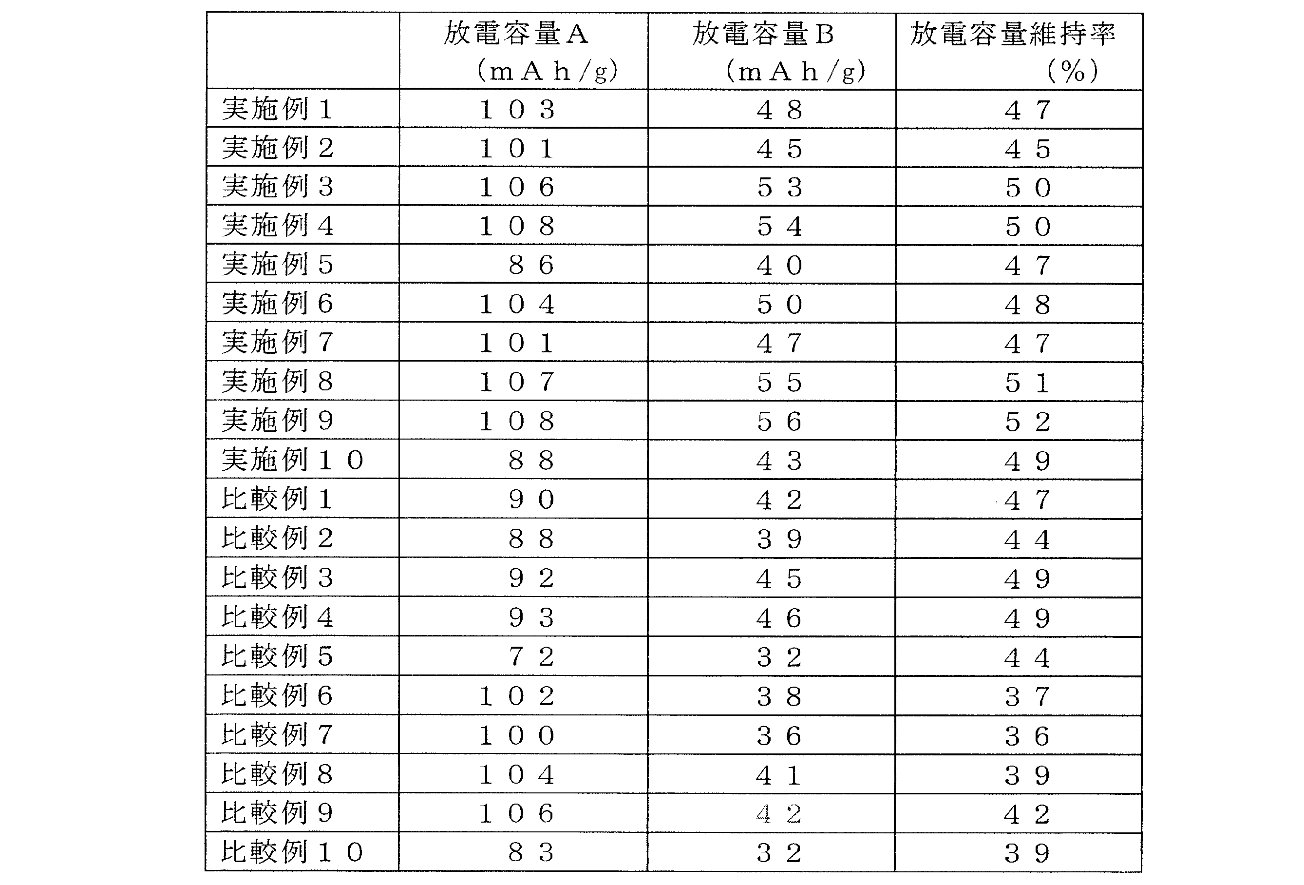
<評価結果>
表1に示すように、ポリビニルブチラール及びアクリルポリマーの炭化率は、エチルセルロースの炭化率と比較して著しく低いことが判明した。表2に示すように、炭化率測定結果と同様に、固体電解質層におけるポリビニルブチラール及びアクリルポリマーの残存炭化物量は、エチルセルロースの残存炭化物量と比較して著しく低かった。
また表3に示すように、正極層前駆体及び負極層前駆体にバインダーとしてエチルセルロース、固体電解質層前駆体にバインダーとしてポリビニルブチラールを使用した実施例1~4に示す全固体二次電池は、放電容量Aが100mAh/g以上を示し、放電容量維持率も45%以上を示した。また、正極層前駆体及び負極層前駆体にバインダーとしてエチルセルロース、固体電解質層前駆体にバインダーとしてアクリルポリマーを使用した実施例6~9に示す全固体二次電池も、放電容量Aは100mAh/g以上を示し、放電容量維持率も45%以上を示した。 <Evaluation results>
As shown in Table 1, the carbonization rate of polyvinyl butyral and acrylic polymer was found to be significantly lower than that of ethylcellulose. As shown in Table 2, similarly to the carbonization rate measurement results, the amount of residual carbides of polyvinyl butyral and acrylic polymer in the solid electrolyte layer was significantly lower than the amount of residual carbides of ethyl cellulose.
In addition, as shown in Table 3, the all-solid secondary batteries shown in Examples 1 to 4 using ethyl cellulose as a binder for the positive electrode layer precursor and the negative electrode layer precursor and polyvinyl butyral as the binder for the solid electrolyte layer precursor were discharged. The capacity A was 100 mAh / g or more, and the discharge capacity retention rate was 45% or more. The all-solid secondary batteries shown in Examples 6 to 9 using ethyl cellulose as a binder for the positive electrode layer precursor and the negative electrode layer precursor and an acrylic polymer as the binder for the solid electrolyte layer precursor also had a discharge capacity A of 100 mAh / g. As described above, the discharge capacity retention rate was 45% or more.
一方、正極層、固体電解質層及び負極層の全層の前駆体にバインダーとしてエチルセルロースを使用した比較例1~4に示す全固体二次電池は、放電容量Aが100mAh/gを下回った。
また、正極層、固体電解質層、負極層の全層の前駆体にバインダーとしてポリビニルブチラールを使用した比較例6~9に示す全固体二次電池は、放電容量Aは100mAh/g以上を示したが、放電容量Bは低く、実施例1~4、6~9の放電容量維持率を下回った。 On the other hand, the discharge capacity A of the all solid secondary batteries shown in Comparative Examples 1 to 4 in which ethyl cellulose was used as a binder for the precursor of all layers of the positive electrode layer, the solid electrolyte layer, and the negative electrode layer was less than 100 mAh / g.
In addition, the all-solid secondary batteries shown in Comparative Examples 6 to 9 using polyvinyl butyral as a binder for the precursors of all layers of the positive electrode layer, the solid electrolyte layer, and the negative electrode layer had a discharge capacity A of 100 mAh / g or more. However, the discharge capacity B was low and was lower than the discharge capacity retention ratios of Examples 1 to 4 and 6 to 9.
さらに、直列全固体二次電池においても上記の単層全固体二次電池と同様の傾向を示し、放電容量Aは実施例5、10、比較例10で大差なく、比較例5を上回った。また、放電容量Bは実施例5、10が比較例5、10を上回った。
以上より、固体電解質層前駆体のバインダーとして、炭化率の低いポリビニルブチラール又はアクリルポリマーを使用することで、正極層と負極層間のマイクロショートが抑制されて、高い放電容量Aを示すことが確認された。また、正極層及び負極層の前駆体のバインダーとして、炭化率の高いエチルセルロースを使用することで、正極層及び負極層の電子伝導度が向上して、高い放電容量B及び高い放電容量維持率を示すことが確認された。 Further, the series all-solid secondary battery also showed the same tendency as the single-layer all-solid secondary battery, and the discharge capacity A was much higher than that of Comparative Example 5 in Examples 5 and 10 and Comparative Example 10. Moreover, the discharge capacity B of Examples 5 and 10 exceeded that of Comparative Examples 5 and 10.
From the above, it was confirmed that by using polyvinyl butyral or acrylic polymer having a low carbonization rate as the binder of the solid electrolyte layer precursor, the micro short-circuit between the positive electrode layer and the negative electrode layer is suppressed and a high discharge capacity A is exhibited. It was. Further, by using ethyl cellulose having a high carbonization rate as a binder for the precursor of the positive electrode layer and the negative electrode layer, the electron conductivity of the positive electrode layer and the negative electrode layer is improved, and a high discharge capacity B and a high discharge capacity maintenance rate are achieved. It was confirmed to show.
以上、本願が優先権を主張する、日本国特許出願2016-032359号(2016年2月23日出願)の全内容は、参照により本開示の一部をなす。
また、各実施形態により本発明を説明したが、本発明の範囲は、図示され記載された例示的な実施形態に限定されるものではなく、本発明が目的とするものと均等な効果をもたらす全ての実施形態をも含む。さらに、本発明の範囲は、請求項により画される発明の特徴の組合せに限定されるものではなく、全ての開示されたそれぞれの特徴のうち特定の特徴のあらゆる所望する組合せによって画されうる。 As described above, the entire contents of Japanese Patent Application No. 2016-032359 (filed on February 23, 2016), to which the present application claims priority, form part of the present disclosure by reference.
Further, although the present invention has been described by each embodiment, the scope of the present invention is not limited to the illustrated and described exemplary embodiments, and the same effects as those intended by the present invention are brought about. All embodiments are also included. Furthermore, the scope of the invention is not limited to the combinations of features of the invention defined by the claims, but can be defined by any desired combination of specific features among all the disclosed features.
11 負極層ペレット焼成体
12 固体電解質層ペレット焼成体
13 正極層ペレット焼成体
14 未焼成金属集電箔
21 負極層焼成体
22 固体電解質層焼成体
23 正極層焼成体
24 積層焼成体
25 焼成金属集電箔 11 Negative electrode layer pellet firedbody 12 Solid electrolyte layer pellet fired body 13 Positive electrode layer pellet fired body 14 Unfired metal current collector foil 21 Negative electrode layer fired body 22 Solid electrolyte layer fired body 23 Positive electrode layer fired body 24 Laminated fired body 25 Fired metal collection Electric foil
12 固体電解質層ペレット焼成体
13 正極層ペレット焼成体
14 未焼成金属集電箔
21 負極層焼成体
22 固体電解質層焼成体
23 正極層焼成体
24 積層焼成体
25 焼成金属集電箔 11 Negative electrode layer pellet fired
Claims (12)
- 正極層、固体電解質層及び負極層を含む全固体二次電池において、
前記正極層に含まれる単位質量当たりの炭化物量、前記固体電解質層に含まれる単位質量当たりの炭化物量及び前記負極層に含まれる単位質量当たりの炭化物量が、前記正極層>前記固体電解質層、且つ、前記負極層>前記固体電解質層の関係を満足することを特徴とする全固体二次電池。 In the all-solid-state secondary battery including the positive electrode layer, the solid electrolyte layer, and the negative electrode layer,
The amount of carbide per unit mass contained in the positive electrode layer, the amount of carbide per unit mass contained in the solid electrolyte layer, and the amount of carbide per unit mass contained in the negative electrode layer are: positive electrode layer> solid electrolyte layer, And the all-solid-state secondary battery satisfy | fills the relationship of the said negative electrode layer> the said solid electrolyte layer. - 正極層、固体電解質層及び負極層を含む全固体二次電池の製造方法であって、
前記正極層、前記固体電解質層及び前記負極層の前駆体を焼成する工程を含み、
前記正極層、前記固体電解質層及び前記負極層の前駆体はそれぞれ焼成されることにより炭化する樹脂を含有し、
前記正極層の前駆体の焼成後の単位質量当たりの焼成残存炭化物量、前記固体電解質層の前駆体の焼成後の単位質量当たりの焼成残存炭化物量及び前記負極層の前駆体の焼成後の単位質量当たりの焼成残存炭化物量が、前記正極層>前記固体電解質層、且つ、前記負極層>前記固体電解質層の関係を満足するように前記樹脂の種類及び含有量を設定することを特徴とする全固体二次電池の製造方法。 A method for producing an all-solid-state secondary battery including a positive electrode layer, a solid electrolyte layer, and a negative electrode layer,
Firing the precursor of the positive electrode layer, the solid electrolyte layer and the negative electrode layer,
The precursors of the positive electrode layer, the solid electrolyte layer, and the negative electrode layer each contain a resin that is carbonized by firing.
Firing residual carbide amount per unit mass after firing of the positive electrode layer precursor, firing residual carbide amount per unit mass after firing of the solid electrolyte layer precursor, and unit after firing of the negative electrode layer precursor The type and content of the resin are set so that the amount of calcination residual carbide per mass satisfies the relationship of the positive electrode layer> the solid electrolyte layer and the negative electrode layer> the solid electrolyte layer. Manufacturing method of all-solid-state secondary battery. - 前記正極層の前駆体が含有する樹脂の炭化率、前記固体電解質層の前駆体が含有する樹脂の炭化率及び前記負極層の前駆体が含有する樹脂の炭化率が、前記正極層>前記固体電解質層、且つ、前記負極層>前記固体電解質層の関係を満足することを特徴とする請求項2に記載の全固体二次電池の製造方法。 The carbonization rate of the resin contained in the precursor of the positive electrode layer, the carbonization rate of the resin contained in the precursor of the solid electrolyte layer, and the carbonization rate of the resin contained in the precursor of the negative electrode layer are determined as follows. 3. The method for producing an all-solid-state secondary battery according to claim 2, wherein the relationship of the electrolyte layer and the negative electrode layer> the solid electrolyte layer is satisfied.
- 前記正極層、前記固体電解質層及び前記負極層の各前駆体として、
正極層グリーンシート、固体電解質層グリーンシート及び負極層グリーンシートを用いることを特徴とする請求項2又は請求項3に記載の全固体二次電池の製造方法。 As each precursor of the positive electrode layer, the solid electrolyte layer and the negative electrode layer,
The method for producing an all-solid-state secondary battery according to claim 2, wherein a positive electrode layer green sheet, a solid electrolyte layer green sheet, and a negative electrode layer green sheet are used. - 前記正極層、前記固体電解質層及び前記負極層の前駆体として、
正極層グリーンシート、固体電解質層グリーンシート及び負極層グリーンシートをこの順に積層した積層体グリーンシートを用いることを特徴とする請求項2又は請求項3に記載の全固体二次電池の製造方法。 As a precursor of the positive electrode layer, the solid electrolyte layer, and the negative electrode layer,
4. The method for producing an all-solid-state secondary battery according to claim 2, wherein a laminate green sheet in which a positive electrode layer green sheet, a solid electrolyte layer green sheet, and a negative electrode layer green sheet are laminated in this order is used. - 前記正極層、前記固体電解質層及び前記負極層の前駆体として、
集電箔上に、正極層グリーンシート、固体電解質層グリーンシート及び負極層グリーンシートをこの順に積層した集電箔付き積層体グリーンシートを用いることを特徴とする請求項2又は請求項3に記載の全固体二次電池の製造方法。 As a precursor of the positive electrode layer, the solid electrolyte layer, and the negative electrode layer,
The laminate green sheet with current collector foil, in which a positive electrode layer green sheet, a solid electrolyte layer green sheet, and a negative electrode layer green sheet are laminated in this order on the current collector foil, is used. Manufacturing method for all-solid-state secondary battery. - 前記正極層、前記固体電解質層及び前記負極層の前駆体として、
前記集電箔付き積層体グリーンシートを複数積層してなる連続積層体グリーンシートを用いることを特徴とする請求項6に記載の全固体二次電池の製造方法。 As a precursor of the positive electrode layer, the solid electrolyte layer, and the negative electrode layer,
The manufacturing method of the all-solid-state secondary battery of Claim 6 using the continuous laminated body green sheet formed by laminating | stacking two or more said laminated green sheets with a current collector foil. - 正極層グリーンシート、固体電解質層グリーンシート及び負極層グリーンシートがこの順に積層された全固体二次電池用の積層体グリーンシートであって、
前記正極層グリーンシート、前記固体電解質層グリーンシート及び前記負極層グリーンシートはそれぞれ焼成されることにより炭化する樹脂を含有し、
前記正極層グリーンシートの焼成後の単位質量当たりの焼成残存炭化物量、前記固体電解質層グリーンシートの焼成後の単位質量当たりの焼成残存炭化物量及び前記負極層グリーンシートの焼成後の単位質量当たりの焼成残存炭化物量が、前記正極層グリーンシート>前記固体電解質層グリーンシート、且つ、前記負極層グリーンシート>前記固体電解質層グリーンシートの関係を満足するように前記樹脂の種類及び含有量を設定することを特徴とする全固体二次電池用の積層体グリーンシート。 A laminate green sheet for an all-solid secondary battery in which a positive electrode layer green sheet, a solid electrolyte layer green sheet, and a negative electrode layer green sheet are laminated in this order,
The positive electrode layer green sheet, the solid electrolyte layer green sheet, and the negative electrode layer green sheet each contain a resin that is carbonized by firing,
Calcination residual carbide amount per unit mass after firing of the positive electrode layer green sheet, calcination residual carbide amount per unit mass after firing of the solid electrolyte layer green sheet and per unit mass after firing of the negative electrode layer green sheet The type and content of the resin are set so that the amount of residual carbide in firing satisfies the relationship of the positive electrode layer green sheet> the solid electrolyte layer green sheet and the negative electrode layer green sheet> the solid electrolyte layer green sheet. A laminated green sheet for an all-solid-state secondary battery. - 前記正極層グリーンシートが含有する樹脂の炭化率、前記固体電解質層グリーンシートが含有する樹脂の炭化率及び前記負極層グリーンシートが含有する樹脂の炭化率が、前記正極層グリーンシート>前記固体電解質層グリーンシート、且つ、前記負極層グリーンシート>前記固体電解質層グリーンシートの関係を満足することを特徴とする請求項8に記載の全固体二次電池用の積層体グリーンシート。 The carbonization rate of the resin contained in the positive electrode layer green sheet, the carbonization rate of the resin contained in the solid electrolyte layer green sheet, and the carbonization rate of the resin contained in the negative electrode layer green sheet are determined as follows: the positive electrode layer green sheet> the solid electrolyte The multilayer green sheet for an all-solid-state secondary battery according to claim 8, wherein a relationship of layer green sheet and negative electrode layer green sheet> solid electrolyte layer green sheet is satisfied.
- 集電箔上に正極層グリーンシート、固体電解質層グリーンシート及び負極層グリーンシートがこの順に積層された全固体二次電池用の集電箔付き積層体グリーンシートであって、
前記正極層グリーンシート、前記固体電解質層グリーンシート及び前記負極層グリーンシートはそれぞれ焼成されることにより炭化する樹脂を含有し、
前記正極層グリーンシートの焼成後の単位質量当たりの焼成残存炭化物量、前記固体電解質層グリーンシートの焼成後の単位質量当たりの焼成残存炭化物量及び前記負極層グリーンシートの焼成後の単位質量当たりの焼成残存炭化物量が、前記正極層グリーンシート>前記固体電解質層グリーンシート、且つ、前記負極層グリーンシート>前記固体電解質層グリーンシートの関係を満足するように前記樹脂の種類及び含有量を設定することを特徴とする全固体二次電池用の集電箔付き積層体グリーンシート。 A green sheet with a current collector foil for an all-solid-state secondary battery in which a positive electrode layer green sheet, a solid electrolyte layer green sheet and a negative electrode layer green sheet are laminated in this order on a current collector foil,
The positive electrode layer green sheet, the solid electrolyte layer green sheet, and the negative electrode layer green sheet each contain a resin that is carbonized by firing,
Calcination residual carbide amount per unit mass after firing of the positive electrode layer green sheet, calcination residual carbide amount per unit mass after firing of the solid electrolyte layer green sheet and per unit mass after firing of the negative electrode layer green sheet The type and content of the resin are set so that the amount of residual carbide in firing satisfies the relationship of the positive electrode layer green sheet> the solid electrolyte layer green sheet and the negative electrode layer green sheet> the solid electrolyte layer green sheet. A laminate green sheet with a current collector foil for an all-solid-state secondary battery. - 前記正極層グリーンシートが含有する樹脂の炭化率、前記固体電解質層グリーンシートが含有する樹脂の炭化率及び前記負極層グリーンシートが含有する樹脂の炭化率が、前記正極層グリーンシート>前記固体電解質層グリーンシート、且つ、前記負極層グリーンシート>前記固体電解質層グリーンシートの関係を満足することを特徴とする請求項10に記載の全固体二次電池用の集電箔付き積層体グリーンシート。 The carbonization rate of the resin contained in the positive electrode layer green sheet, the carbonization rate of the resin contained in the solid electrolyte layer green sheet, and the carbonization rate of the resin contained in the negative electrode layer green sheet are determined as follows: the positive electrode layer green sheet> the solid electrolyte 11. The laminated green sheet with current collector foil for an all-solid-state secondary battery according to claim 10, wherein the relationship of layer green sheet and negative electrode layer green sheet> solid electrolyte layer green sheet is satisfied.
- 請求項10又は請求項11に記載の集電箔付き積層体グリーンシートを複数積層してなることを特徴とする全固体二次電池用の連続積層体グリーンシート。 A continuous laminate green sheet for an all-solid-state secondary battery, comprising a plurality of laminate green sheets with current collector foils according to claim 10 or 11.
Applications Claiming Priority (2)
| Application Number | Priority Date | Filing Date | Title |
|---|---|---|---|
| JP2016032359A JP2017152146A (en) | 2016-02-23 | 2016-02-23 | All-solid type secondary battery, method for manufacturing all-solid type secondary battery, laminate green sheet for all-solid type secondary battery, current collector foil-attached laminate green sheet for all-solid type secondary battery, and continuous laminate green sheet for all-solid type secondary battery |
| JP2016-032359 | 2016-02-23 |
Publications (1)
| Publication Number | Publication Date |
|---|---|
| WO2017145657A1 true WO2017145657A1 (en) | 2017-08-31 |
Family
ID=59685242
Family Applications (1)
| Application Number | Title | Priority Date | Filing Date |
|---|---|---|---|
| PCT/JP2017/003227 WO2017145657A1 (en) | 2016-02-23 | 2017-01-30 | All-solid secondary battery, method for producing all-solid secondary battery, stacked green sheet for all-solid secondary battery, stacked green sheet with current collector foil for all-solid secondary battery, and continuous stacked green sheet for all-solid secondary battery |
Country Status (2)
| Country | Link |
|---|---|
| JP (1) | JP2017152146A (en) |
| WO (1) | WO2017145657A1 (en) |
Cited By (1)
| Publication number | Priority date | Publication date | Assignee | Title |
|---|---|---|---|---|
| CN112930611A (en) * | 2018-12-28 | 2021-06-08 | 松下知识产权经营株式会社 | Battery and method for manufacturing battery |
Families Citing this family (4)
| Publication number | Priority date | Publication date | Assignee | Title |
|---|---|---|---|---|
| JP6943208B2 (en) * | 2018-03-12 | 2021-09-29 | トヨタ自動車株式会社 | Manufacturing method of all-solid-state battery and all-solid-state battery |
| JP2019192609A (en) * | 2018-04-27 | 2019-10-31 | 日本碍子株式会社 | All-solid lithium battery and method of manufacturing the same |
| WO2022118928A1 (en) * | 2020-12-03 | 2022-06-09 | マクセル株式会社 | All-solid-state battery system |
| WO2023189374A1 (en) * | 2022-03-28 | 2023-10-05 | 株式会社村田製作所 | Solid-state battery electrode and method for manufacturing same, solid-state battery and method for manufacturing same, and battery package |
Citations (5)
| Publication number | Priority date | Publication date | Assignee | Title |
|---|---|---|---|---|
| WO2011132627A1 (en) * | 2010-04-23 | 2011-10-27 | 株式会社 村田製作所 | All-solid state secondary battery and production method for same |
| JP2012238545A (en) * | 2011-05-13 | 2012-12-06 | Toyota Motor Corp | Method for manufacturing all-solid battery |
| JP2014116156A (en) * | 2012-12-07 | 2014-06-26 | Mitsubishi Electric Corp | All-solid-state battery and manufacturing method therefor and circuit board using the same |
| JP2015060737A (en) * | 2013-09-19 | 2015-03-30 | 株式会社村田製作所 | All solid state battery and process of manufacturing the same |
| JP2015069843A (en) * | 2013-09-30 | 2015-04-13 | Fdk株式会社 | All-solid battery, and method for manufacturing all-solid battery |
-
2016
- 2016-02-23 JP JP2016032359A patent/JP2017152146A/en active Pending
-
2017
- 2017-01-30 WO PCT/JP2017/003227 patent/WO2017145657A1/en active Application Filing
Patent Citations (5)
| Publication number | Priority date | Publication date | Assignee | Title |
|---|---|---|---|---|
| WO2011132627A1 (en) * | 2010-04-23 | 2011-10-27 | 株式会社 村田製作所 | All-solid state secondary battery and production method for same |
| JP2012238545A (en) * | 2011-05-13 | 2012-12-06 | Toyota Motor Corp | Method for manufacturing all-solid battery |
| JP2014116156A (en) * | 2012-12-07 | 2014-06-26 | Mitsubishi Electric Corp | All-solid-state battery and manufacturing method therefor and circuit board using the same |
| JP2015060737A (en) * | 2013-09-19 | 2015-03-30 | 株式会社村田製作所 | All solid state battery and process of manufacturing the same |
| JP2015069843A (en) * | 2013-09-30 | 2015-04-13 | Fdk株式会社 | All-solid battery, and method for manufacturing all-solid battery |
Cited By (1)
| Publication number | Priority date | Publication date | Assignee | Title |
|---|---|---|---|---|
| CN112930611A (en) * | 2018-12-28 | 2021-06-08 | 松下知识产权经营株式会社 | Battery and method for manufacturing battery |
Also Published As
| Publication number | Publication date |
|---|---|
| JP2017152146A (en) | 2017-08-31 |
Similar Documents
| Publication | Publication Date | Title |
|---|---|---|
| JP5717318B2 (en) | All solid state secondary battery | |
| WO2017145657A1 (en) | All-solid secondary battery, method for producing all-solid secondary battery, stacked green sheet for all-solid secondary battery, stacked green sheet with current collector foil for all-solid secondary battery, and continuous stacked green sheet for all-solid secondary battery | |
| JP4797105B2 (en) | Lithium ion secondary battery and manufacturing method thereof | |
| CN102610830B (en) | Lithium ion battery | |
| WO2013011931A1 (en) | All solid-state battery and method of manufacturing same | |
| JP2017152147A (en) | Composite active material secondary particle, laminate green sheet, all-solid type secondary battery and manufacturing methods thereof | |
| WO2011125481A1 (en) | Lithium ion secondary battery and method for producing same | |
| WO2017146133A1 (en) | Stacked green sheet, continuous stacked green sheet, stacked sintered body, continuous stacked sintered body, and all-solid secondary battery, and method for producing stacked green sheet, method for producing continuous stacked green sheet, and method for producing all-solid secondary battery | |
| JP2018063850A (en) | Laminate green sheet, all-solid type secondary battery, and method for fabricating the same | |
| CA2719764A1 (en) | High energy high power electrodes and batteries | |
| JP2010140725A (en) | Lithium-ion secondary battery and its manufacturing method | |
| JP6943023B2 (en) | Laminated green sheet, all-solid-state secondary battery and its manufacturing method | |
| WO2014170998A1 (en) | All-solid-state lithium-ion secondary battery | |
| JP7009761B2 (en) | All-solid-state secondary battery | |
| US20200052279A1 (en) | Method of preparing energy storage electrodes | |
| JP5804208B2 (en) | All-solid battery, unfired laminate for all-solid battery, and method for producing all-solid battery | |
| KR20170034606A (en) | Cathode of three dimensional lithium secondary battery and method of fabricating the same | |
| JP7183529B2 (en) | LAMINATED GREEN SHEET, ALL-SOLID SECONDARY BATTERY AND MANUFACTURING METHOD THEREOF | |
| JP7107389B2 (en) | solid state battery | |
| CN111384433A (en) | Solid electrolyte laminate and solid battery | |
| JP2018077989A (en) | Laminate green sheet and all-solid type secondary battery | |
| WO2021010231A1 (en) | Solid-state battery | |
| JP6855749B2 (en) | Slurries, laminated green sheets, all-solid-state secondary batteries and their manufacturing methods | |
| WO2013073290A1 (en) | All-solid-state battery and method for manufacturing same | |
| JP2018063808A (en) | Laminate green sheet, all-solid type secondary battery, and fabricating methods thereof |
Legal Events
| Date | Code | Title | Description |
|---|---|---|---|
| NENP | Non-entry into the national phase |
Ref country code: DE |
|
| 121 | Ep: the epo has been informed by wipo that ep was designated in this application |
Ref document number: 17756099 Country of ref document: EP Kind code of ref document: A1 |
|
| 122 | Ep: pct application non-entry in european phase |
Ref document number: 17756099 Country of ref document: EP Kind code of ref document: A1 |