WO2017142095A1 - Endoscope light source device and endoscope system - Google Patents
Endoscope light source device and endoscope system Download PDFInfo
- Publication number
- WO2017142095A1 WO2017142095A1 PCT/JP2017/006122 JP2017006122W WO2017142095A1 WO 2017142095 A1 WO2017142095 A1 WO 2017142095A1 JP 2017006122 W JP2017006122 W JP 2017006122W WO 2017142095 A1 WO2017142095 A1 WO 2017142095A1
- Authority
- WO
- WIPO (PCT)
- Prior art keywords
- light
- wavelength
- light source
- phosphor
- emitted
- Prior art date
Links
Images


Classifications
-
- A—HUMAN NECESSITIES
- A61—MEDICAL OR VETERINARY SCIENCE; HYGIENE
- A61B—DIAGNOSIS; SURGERY; IDENTIFICATION
- A61B1/00—Instruments for performing medical examinations of the interior of cavities or tubes of the body by visual or photographical inspection, e.g. endoscopes; Illuminating arrangements therefor
- A61B1/06—Instruments for performing medical examinations of the interior of cavities or tubes of the body by visual or photographical inspection, e.g. endoscopes; Illuminating arrangements therefor with illuminating arrangements
- A61B1/0655—Control therefor
Definitions
- Patent Document 1 Japanese Unexamined Patent Application Publication No. 2009-165889
- Patent Document 1 describes a specific configuration of a light source device used in this type of endoscope system.
- the light source device described in Patent Document 1 uses a xenon lamp as a light source.
- solid-state light-emitting elements such as light-emitting diodes (LEDs: Light Emitting Diodes) have been increasing in brightness, and there is a demand for using a solid-state light-emitting element having a longer life as a light source.
- the wavelength band of a solid state light emitting device is narrower than that of a xenon lamp. Therefore, for example, pseudo white light is generated by combining an LED emitting blue LED light and a phosphor emitting yellow fluorescence.
- pseudo white light is generated by combining an LED emitting blue LED light and a phosphor emitting yellow fluorescence.
- the spectral intensity distribution of normal light does not become flat in the visible light band and the color reproducibility of the photographed image of the photographed subject is poor only by combining the LED and the phosphor in this way.
- the first phosphor and the second phosphor are excited by, for example, light in the first wavelength band emitted from the first solid state light emitting device.
- the first phosphor and the second phosphor are excited by, for example, light in the second wavelength band emitted from the second solid state light emitting device.
- the phosphor insertion / extraction means extracts the first phosphor from the optical path of the light emitted from the first solid state light emitting device, and the filter
- the phosphor insertion / extraction means inserts the first phosphor into the optical path of the light emitted from the first solid state light emitting device.
- an endoscope system includes the above-described endoscope light source device and an endoscope.
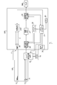
- FIG. 1 is a block diagram showing a configuration of an electronic endoscope system 1 including an endoscope light source device 201 according to the first embodiment of the present invention.
- the electronic endoscope system 1 is a system specialized for medical use, and includes an electronic scope 100, a processor 200, and a monitor 300.
- the processor 200 includes a system controller 21 and a timing controller 22.
- the system controller 21 executes various programs stored in the memory 23 and controls the entire electronic endoscope system 1 in an integrated manner.
- the system controller 21 is connected to the operation panel 24.
- the system controller 21 changes each operation of the electronic endoscope system 1 and parameters for each operation in accordance with an instruction from the operator input from the operation panel 24.
- the input instruction by the operator includes, for example, an instruction to switch the observation mode of the electronic endoscope system 1.
- the observation mode includes a normal observation mode and a special observation mode. Details of each observation mode will be described later.
- the timing controller 22 outputs a clock pulse for adjusting the operation timing of each unit to each circuit in the electronic endoscope system 1.
- the processor 200 includes a light source device 201.
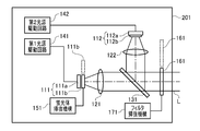
- FIG. 2 is a block diagram of the light source device 201 according to the first embodiment of the present invention.
- the light source device 201 includes a first light source unit 111 and a second light source unit 112.
- the first and second light source units 111 and 112 are individually controlled to emit light by the first and second light source drive circuits 141 and 142, respectively.
- the first light source unit 111 includes a purple light emitting diode (LED: Light Emitting Diode) 111a that emits light in a purple wavelength band (for example, a wavelength of 395 to 435 nm) and a blue phosphor 111b.
- the blue phosphor 111b is excited by the purple LED light emitted from the purple LED 111a and emits fluorescence in a blue wavelength band (for example, a wavelength of 430 to 550 nm).
- the second light source unit 112 includes a blue LED 112a that emits light in a blue wavelength band (for example, a wavelength of 420 to 480 nm), and a yellow phosphor 112b.
- the yellow phosphor 112b is excited by the blue LED light emitted from the blue LED 112a, and emits fluorescence in a yellow wavelength band (for example, a wavelength is 420 to 700 nm).
- the yellow phosphor 112b is attached on the light emitting surface of the blue LED 112a, and unlike the blue phosphor 111b, it cannot be inserted into and removed from the optical path of the blue LED light.
- Collimating lenses 121 and 122 are arranged in front of the light source units 111 and 112 in the light emission direction, respectively.
- the light emitted from the first light source unit 111 is converted into parallel light by the collimator lens 121 and is incident on the dichroic mirror 131.
- the light emitted from the second light source unit 112 is converted into parallel light by the collimator lens 122 and is incident on the dichroic mirror 131.
- the dichroic mirror 131 combines the optical path of the light emitted from the first light source unit 111 and the optical path of the light emitted from the second light source unit 112.
- the wavelength limiting filter 161 has a characteristic of transmitting only light in a specific wavelength band.
- FIG. 3 shows the spectral transmission characteristic T161 of the wavelength limiting filter 161.
- the horizontal axis of the graph shown in FIG. 3 indicates the wavelength (nm), and the vertical axis indicates the transmittance.
- the wavelength limiting filter 161 has a transmittance of about 1 (100%) for light having a wavelength of about 415 nm (more specifically, 390 nm to 430 nm) and a wavelength of about 550 nm (more specifically, 520 nm to 580 nm).
- the transmittance for light in other wavelength bands is approximately 0 (0%).
- FIG. 4 is a block diagram conceptually showing only the light source units 111 and 112, the dichroic mirror 131, and the wavelength limiting filter 161 in the light source device 201. Since the blue phosphor 111b is a separate body from the purple LED 111a, the blue phosphor 111b and the purple LED 111a are shown as separate blocks in FIG. On the other hand, since the yellow phosphor 112b is attached to the light emitting surface of the blue LED 112a and is configured integrally with the blue LED 112a, the yellow phosphor 112b and the blue LED 112a are shown in one block in FIG. Yes.
- the dichroic mirror 131 synthesizes optical paths of light having different wavelengths. Therefore, in FIG. 4, the dichroic mirror 131 is indicated by an addition symbol “+”. In FIG. 4, the collimating lenses 121 and 122 disposed in front of the light source units 111 and 112 are omitted.
- each arrow indicates an optical path of light.
- the purple LED light emitted from the purple LED 111a of the first light source unit 111 and the blue fluorescence emitted from the blue phosphor 111b are emitted in the same optical path.
- the blue LED light emitted from the blue LED of the second light source unit 112 and the yellow fluorescence emitted from the yellow phosphor are emitted in the same optical path.
- the optical path of the light emitted from the first light source unit 111 and the optical path of the light emitted from the second light source unit 112 are combined by the dichroic mirror 131.
- the light whose optical path is synthesized by the dichroic mirror 131 is emitted as the irradiation light L from the light source device 201.
- the solid-state imaging device 14 is a single-plate color CCD (Charge Coupled Device) image sensor having a Bayer pixel arrangement.
- the solid-state imaging device 14 accumulates an optical image formed by each pixel on the light receiving surface as a charge corresponding to the amount of light, and generates R (Red), G (Green), and B (Blue) image signals. Output.
- the solid-state imaging device 14 is not limited to a CCD image sensor, and may be replaced with a CMOS (Complementary Metal Oxide Semiconductor) image sensor or other types of imaging devices.
- the solid-state image sensor 14 may also be one having a complementary color filter mounted thereon.
- the driver signal processing circuit 15 also accesses the memory 16 and reads the unique information of the electronic scope 100.
- the unique information of the electronic scope 100 recorded in the memory 16 includes, for example, the number and sensitivity of the solid-state imaging device 14, an operable frame rate, a model number, and the like.
- the driver signal processing circuit 15 outputs the unique information read from the memory 16 to the system controller 21.
- the system controller 21 performs various calculations based on the unique information of the electronic scope 100 and generates a control signal.
- the system controller 21 uses the generated control signal to control the operation and timing of various circuits in the processor 200 so that processing suitable for the electronic scope 100 connected to the processor 200 is performed.
- the timing controller 22 supplies clock pulses to the driver signal processing circuit 15 according to the timing control by the system controller 21.
- the driver signal processing circuit 15 drives and controls the solid-state imaging device 14 at a timing synchronized with the frame rate of the video processed on the processor 200 side in accordance with the clock pulse supplied from the timing controller 22.
- the pre-stage signal processing circuit 26 performs predetermined signal processing such as demosaic processing, matrix calculation, and Y / C separation on the image signal input from the driver signal processing circuit 15 in one frame period, and outputs it to the image memory 27. To do.
- the image memory 27 buffers the image signal input from the upstream signal processing circuit 26 and outputs it to the downstream signal processing circuit 28 according to the timing control by the timing controller 22.
- the post-stage signal processing circuit 28 processes the image signal input from the image memory 27 to generate screen data for monitor display, and converts the generated screen data for monitor display into a predetermined video format signal.
- the converted video format signal is output to the monitor 300. Thereby, the image of the subject is displayed on the display screen of the monitor 300.
- the electronic endoscope system 1 of the present embodiment has a plurality of observation modes including a normal observation mode and a special observation mode.
- Each observation mode is switched manually or automatically depending on the subject to be observed. For example, when it is desired to observe the subject illuminated with normal light, the observation mode is switched to the normal observation mode.
- the normal light is, for example, white light or pseudo white light.
- White light has a flat spectral intensity distribution in the visible light band.
- the pseudo-white light has a spectral intensity distribution that is not flat, and light in a plurality of wavelength bands is mixed. For example, when it is desired to obtain a captured image in which a specific living tissue is emphasized by illuminating the subject with special light, the observation mode is switched to the special observation mode.
- ⁇ Blood containing hemoglobin flows in the surface blood vessels. It is known that hemoglobin has absorbance peaks near wavelengths of 415 nm and 550 nm. Therefore, by irradiating the subject with special light suitable for emphasizing the superficial blood vessels (specifically, light having a higher intensity near the wavelength of 415 nm where the absorbance of hemoglobin is peak than other wavelength bands). A captured image in which the superficial blood vessels are emphasized can be obtained. Special light having a high intensity near the wavelength of 550 nm has a relatively high absorbance even for the surface blood vessels. In other words, special light having a high intensity in the vicinity of a wavelength of 550 nm also contributes to highlighting of the surface blood vessels.
- the brightness of the photographed image is maintained while maintaining the state where the surface blood vessels are emphasized. Can be brightened.
- narrowband light special light
- normal observation mode blood vessels in each layer such as the surface layer, middle layer, and deep layer
- Narrow band observation suitable for clearly grasping the state can be performed.
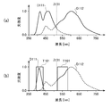
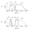
- FIG. 5 shows the spectral intensity distribution of the irradiation light L emitted from the light source device 201 in each observation mode.
- 5A shows a spectral intensity distribution of the irradiation light L (normal light) in the normal observation mode
- FIG. 5B shows a spectral intensity distribution of the irradiation light L (special light) in the special observation mode.
- the horizontal axis of the spectral intensity distribution shown in FIG. 5 indicates the wavelength (nm), and the vertical axis indicates the intensity of the irradiation light L. Note that the vertical axis is standardized so that the maximum intensity value is 1.
- the first light source unit 111 and the second light source unit 112 are driven to emit light after the blue phosphor 111b is inserted in the optical path. At this time, the wavelength limiting filter 161 is removed from the optical path of the irradiation light L.
- the spectral intensity distribution D111 of light emitted from the first light source unit 111 has peaks at a wavelength of about 415 nm and a wavelength of about 470 nm.
- a wavelength having the highest intensity among the specific wavelengths is referred to as a peak wavelength.
- the wavelength having the highest intensity is called the peak wavelength.
- the two wavelengths that are the intensity peaks of the spectral intensity distribution D111 are the peak wavelength of the light emitted from the purple LED 111a and the peak wavelength of the spectral intensity distribution of the fluorescence emitted from the blue phosphor 111b.
- the spectral intensity distribution D112 of light emitted from the second light source unit 112 has peaks at a wavelength of about 450 nm and a wavelength of about 600 nm. These two wavelengths are respectively the peak wavelength of the intensity distribution of the light emitted from the blue LED 112a and the peak wavelength of the spectral intensity distribution of the fluorescence emitted from the yellow phosphor 112b.
- the spectral intensity distribution D111 shown in FIG. 5A has substantially the same peak intensity of purple LED light and blue fluorescence, but the present invention is not limited to this.
- the ratio of the intensity of the purple LED light emitted from the first light source unit 111 to the intensity of blue fluorescence can be freely changed by changing the type and amount of use of the blue phosphor 111b.
- the spectral intensity distribution D112 shown in FIG. 5A has a larger ratio of the intensity of yellow fluorescence than the blue LED light, but the present invention is not limited to this.
- the ratio between the blue LED light emitted from the second light source unit 112 and the yellow fluorescence can be freely changed by changing the type and amount of use of the yellow phosphor 112b.
- the maximum intensity is set to 1, but the present invention is not limited to this.
- the intensity ratio of the light emitted from the light source units 111 and 112 can be arbitrarily set according to the subject to be observed, the photographing mode, and the operator's preference.
- the cutoff wavelength ⁇ 131 of the dichroic mirror 131 is indicated by a dotted line.
- the dichroic mirror 131 has a cutoff wavelength ⁇ 131 of about 520 nm, transmits light in a wavelength band shorter than the cutoff wavelength ⁇ 131, and reflects light in a wavelength band longer than the cutoff wavelength ⁇ 131. Therefore, in the spectral intensity distribution D111 shown in FIG. 5A, light in the wavelength band indicated by the solid line is transmitted through the dichroic mirror 131, and light in the wavelength band indicated by the broken line is reflected by the dichroic mirror 131. Also, in the spectral intensity distribution D112 shown in FIG.
- the optical paths of the light emitted from the light source units 111 and 112 are synthesized by the dichroic mirror 131, and the light source device 201 emits light having a wide wavelength band from the ultraviolet region (part of the near ultraviolet) to the red region.
- Light L normal light
- the spectral intensity distribution of the irradiation light L is the sum of the areas indicated by the solid lines in the spectral intensity distributions D111 and D112 shown in FIG.
- two phosphors 111b and 112b having a wide wavelength band and different wavelength bands are provided. Therefore, the spectral intensity distribution of the irradiation light L (normal light) is closer to flat in the visible light band than when no phosphor is used or when only one type of phosphor is used. Thereby, the subject is illuminated with the irradiation light L (normal light) close to natural white light, and a color photographed image with high color reproducibility can be obtained.
- the first light source unit 111 and the second light source unit 112 are driven to emit light after the blue phosphor 111b is removed from the optical path.
- the wavelength limiting filter 161 is inserted on the optical path of the irradiation light L.
- FIG. 5B shows the intensity distribution of light emitted from the light source units 111 and 112 and the spectral transmission characteristic T161 of the wavelength limiting filter 161.
- Light emitted from the light source device 201 as irradiation light L (special light) is light whose optical path is combined by the dichroic mirror 131 and transmitted through the wavelength limiting filter 161. Therefore, the spectral intensity distribution of the irradiation light L (special light) is the sum of the areas indicated by the solid lines in the spectral intensity distributions D111 and D112 shown in FIG.
- the electronic endoscope system 1 When the electronic endoscope system 1 is in the special observation mode, since the blue phosphor 111b is removed from the optical path, the light emitted from the purple LED 111a is not used to excite the blue phosphor 111b. It is possible to increase the intensity of light in the vicinity of a wavelength of 415 nm, which is the peak of the absorbance. Also, the wavelength limiting filter 161 irradiates the subject with only light having a wavelength of about 550 nm, which is another peak of hemoglobin absorbance, out of light emitted from the second light source unit 112. Thereby, the brightness
- the light paths of the light emitted from the light source units 111 and 112 are combined by the dichroic mirror 131. At this time, since the wavelength bands of the light emitted from the light source units 111 and 112 are different from each other, the loss of the light amount can be minimized when the optical paths in the dichroic mirror 131 are combined.
- the spectral intensity distribution of the irradiation light L emitted from the light source device 201 is switched by inserting / removing the wavelength limiting filter 161 on the optical path of the irradiation light L.
- the processor 200 does not need to have the plurality of light source devices 201 in accordance with the spectral intensity distribution of the desired irradiation light L, and the configuration of the processor 200 can be simplified and downsized.
- the peak intensities of the spectral intensity distributions D111 and D112 are all set to 1, but the present invention is not limited to this. It is not limited to.
- the second light source unit 112 may be driven to emit light so that the drive current is smaller and the intensity is lower than that in the normal observation mode.
- the intensity around the wavelength of 415 nm, which is the peak of hemoglobin absorbance is relatively higher than the intensity of other wavelength bands (that is, becomes narrowband light), and a captured image in which the surface blood vessels are more emphasized is obtained.
- the blue phosphor 111b is supported by the phosphor insertion / extraction mechanism 151 so that it can be inserted into and removed from the optical path.
- the present invention is not limited to this.
- the blue phosphor 111b is not insertable / removable on the optical path, and may be attached on the light emitting surface of the purple LED 111a.
- blue fluorescence is also emitted from the first light source unit 111.
- the blue fluorescence is cut by the wavelength limiting filter 161, the enhancement effect of the surface blood vessels is not reduced by the blue fluorescence.
- an endoscope light source device according to a second embodiment of the present invention will be described.
- the light source device according to the second embodiment is also used in the electronic endoscope system 1 in the same manner as the light source device 201 according to the first embodiment.
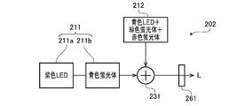
- FIG. 6 is a block diagram conceptually showing only a light source unit, a dichroic mirror, and a wavelength limiting filter in the light source device 202 according to the second embodiment.
- the light source device 202 includes a first light source unit 211, a second light source unit 212, a dichroic mirror 231, and a wavelength limiting filter 261.
- the light source units 211 and 212 are individually controlled to emit light by a first light source drive circuit and a second light source drive circuit (not shown).
- the first light source unit 211 has a purple LED 211a that emits light in a purple wavelength band (for example, a wavelength of 395 to 435 nm) and a blue phosphor 211b.
- the blue phosphor 211b is excited by the purple LED light emitted from the purple LED 211a and emits fluorescence in a blue wavelength band (for example, a wavelength of 430 to 550 nm).
- the blue phosphor 211b is supported by an unillustrated phosphor insertion / extraction mechanism so that the blue phosphor 211b can be inserted into and removed from the optical path of the purple LED light emitted from the purple LED 211a.
- the second light source unit 212 includes a blue LED, a green phosphor, and a red phosphor that emit light in a blue wavelength band (for example, a wavelength of 420 to 480 nm).
- the green phosphor is excited by blue LED light emitted from the blue LED, and emits fluorescence in a green wavelength band (for example, a wavelength of 510 to 630 nm).
- the red phosphor is excited by the blue LED light emitted from the blue LED and emits fluorescence in the red wavelength band (for example, the wavelength is 550 to 750 nm).
- the green phosphor and the red phosphor may be arranged side by side along the emission direction of the blue LED light, or may be arranged side by side in a direction perpendicular to the emission direction of the blue LED light.
- the green phosphor and the red phosphor may be prepared as a single phosphor by mixing the materials.
- a collimating lens (not shown) is arranged in front of the light source units 211 and 212 in the emission direction.
- the light emitted from the first light source unit 211 is converted into parallel light by the collimator lens and is incident on the dichroic mirror 231.
- the light emitted from the second light source unit 212 is converted into parallel light by the collimator lens and is incident on the dichroic mirror 231.
- the dichroic mirror 231 combines the optical path of the light emitted from the first light source unit 211 and the optical path of the light emitted from the second light source unit 212.
- the light whose optical path is synthesized by the dichroic mirror 231 is emitted as the irradiation light L toward the wavelength limiting filter 261.
- the spectral transmission characteristic of the wavelength limiting filter 261 is the same as the spectral transmission characteristic of the wavelength limiting filter 161 of the first embodiment.
- the wavelength limiting filter 261 is removed from the optical path of the irradiation light L.
- the irradiation light L is emitted from the light source device 202 without the wavelength being limited by the wavelength limiting filter 261.
- the wavelength limiting filter 261 is inserted in the optical path of the irradiation light L. In this case, of the irradiation light L, only light having a wavelength near 415 nm and a wavelength near 550 nm is emitted from the light source device 202.
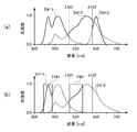
- FIG. 7 is a view similar to FIG. 5 and shows the spectral intensity distribution of the irradiation light L emitted from the light source device 202 in each observation mode.
- FIG. 7B the spectral transmission characteristic T261 of the wavelength limiting filter 261 is also shown.
- both the first light source unit 211 and the second light source unit 212 are driven to emit light after the blue phosphor 211b is inserted in the optical path. At this time, the wavelength limiting filter 261 is removed from the optical path of the irradiation light L.
- the spectral intensity distribution D211 of light emitted from the first light source unit 211 has peaks at a wavelength of about 415 nm and a wavelength of about 470 nm. These two wavelengths are the peak wavelength of the intensity distribution of the light emitted from the purple LED 211a and the peak wavelength of the spectral intensity distribution of the fluorescence emitted from the blue phosphor 211b.
- the spectral intensity distribution D212 of light emitted from the second light source unit 212 has peaks at wavelengths of about 450 nm, about 550 nm, and about 650 nm. These three wavelengths are respectively the peak wavelengths of the intensity distribution of the blue LED light, the fluorescence emitted by the green phosphor, and the fluorescence emitted by the red phosphor.
- the cutoff wavelength ⁇ 231 of the dichroic mirror 231 is indicated by a dotted line.
- the dichroic mirror 231 has a cutoff wavelength ⁇ 231 of about 510 nm, transmits light in a wavelength band shorter than the cutoff wavelength ⁇ 231, and reflects light in a wavelength band longer than the cutoff wavelength ⁇ 231. Therefore, in the spectral intensity distribution D211 shown in FIG. 7A, light in the wavelength band indicated by the solid line passes through the dichroic mirror 231 and light in the wavelength band indicated by the broken line is reflected by the dichroic mirror 231. In the spectral intensity distribution D212 shown in FIG. 7A, light in the wavelength band indicated by the solid line is reflected by the dichroic mirror 231 and light in the wavelength band indicated by the broken line passes through the dichroic mirror 231.
- the optical path of the light emitted from each of the light source units 211 and 212 is synthesized by the dichroic mirror 231, and the light source device 202 emits light having a wide wavelength band from the ultraviolet region (part of near ultraviolet) to the red region.
- Light L normal light
- the spectral intensity distribution of the irradiation light L (normal light) is the sum of the areas indicated by the solid lines in the spectral intensity distributions D211 and D212 shown in FIG.
- both the first light source unit 211 and the second light source unit 212 are driven to emit light after the blue phosphor 211b is removed from the optical path. .
- the wavelength limiting filter 261 is inserted on the optical path of the irradiation light L.
- the ratio of light in the vicinity of a wavelength of 415 nm, which is the peak of the absorbance of hemoglobin, in the irradiation light L (special light) is relatively high (that is, narrow-band light), and a captured image in which the surface blood vessels are emphasized is obtained.
- the second light source unit 212 has two phosphors, green and red. Therefore, the spectral intensity distribution of the irradiation light L (normal light) when the electronic endoscope system 1 is in the normal observation mode is more visible than when the second light source unit 212 has one phosphor. It approaches flat in the area. Thereby, in the normal observation mode, the subject can be illuminated with the irradiation light L (normal light) close to natural white light.
- the light source device according to the third embodiment is also used in the electronic endoscope system 1 in the same manner as the light source device 201 according to the first embodiment.
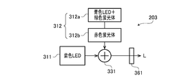
- FIG. 8 is a block diagram conceptually showing only a light source unit, a dichroic mirror, and a wavelength limiting filter in the light source device 203 according to the third embodiment.
- the light source device 203 includes a first light source unit 311, a second light source unit 312, a dichroic mirror 331, and a wavelength limiting filter 361.
- the light source units 311 and 312 are individually controlled to emit light by a first light source drive circuit and a second light source drive circuit (not shown).
- the first light source unit 311 is a purple LED that emits light in a purple wavelength band (for example, a wavelength of 395 to 435 nm).
- the second light source unit 312 includes a phosphor LED 312a and a red phosphor 312b.
- the phosphor LED 312a includes a blue LED that emits light in a blue wavelength band (for example, a wavelength of 430 to 490 nm), and a green phosphor that is attached on the light emitting surface of the blue LED. This green phosphor is excited by blue LED light emitted from a blue LED, and emits fluorescence in a green wavelength band (for example, a wavelength of 460 to 600 nm).
- the red phosphor 312b is excited by the blue LED light emitted from the blue LED, and emits fluorescence in the red wavelength band (for example, the wavelength is 550 to 750 nm).
- the red phosphor 312b is supported by an unillustrated phosphor insertion / extraction mechanism so that the red phosphor 312b can be inserted into and removed from the optical path of light emitted from the blue LED.
- a collimator lens (not shown) is arranged in front of the light source units 311 and 312 in the emission direction.
- the purple LED light emitted from the first light source unit 311 is converted into parallel light by the collimator lens and is incident on the dichroic mirror 331.
- the light emitted from the second light source unit 312, that is, the blue LED light and the green and red fluorescence are converted into parallel light by the collimator lens and are incident on the dichroic mirror 331.
- the dichroic mirror 331 combines the optical path of the light emitted from the first light source unit 311 and the optical path of the light emitted from the second light source unit 312.
- the light whose optical path is synthesized by the dichroic mirror 331 is emitted as irradiation light L toward the wavelength limiting filter 361.
- the spectral transmission characteristic of the wavelength limiting filter 361 is the same as the spectral transmission characteristic of the wavelength limiting filter 161 of the first embodiment.
- the wavelength limiting filter 361 is removed from the optical path of the irradiation light L.
- the irradiation light L is emitted from the light source device 203 without being limited in wavelength by the wavelength limiting filter 361.
- the wavelength limiting filter 361 is inserted into the optical path of the irradiation light L. In this case, of the irradiation light L, only light having a wavelength near 415 nm and a wavelength near 550 nm is emitted from the light source device 203.
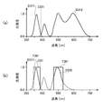
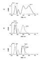
- FIG. 9 is a view similar to FIG. 5 and shows the spectral intensity distribution of the irradiation light L emitted from the light source device 203 in each observation mode.
- FIG. 9B also shows the spectral transmission characteristic T361 of the wavelength limiting filter 361.
- both the light source unit 311 and the light source unit 312 are driven to emit light after the red phosphor 312b is inserted in the optical path.
- the wavelength limiting filter 361 is removed from the optical path of the irradiation light L.
- the spectral intensity distribution D311 of light emitted from the first light source unit 311 has a steep intensity distribution having a peak wavelength of about 415 nm.
- the spectral intensity distribution D312 of light emitted from the second light source unit 312 has peaks at wavelengths of about 470 nm, about 550 nm, and about 630 nm. These three wavelengths are respectively the peak wavelengths of the intensity distribution of blue LED light, green fluorescence, and red fluorescence.
- the cutoff wavelength ⁇ 331 of the dichroic mirror 331 is indicated by a dotted line.
- the dichroic mirror 331 has a cutoff wavelength ⁇ 331 of about 430 nm, transmits light in a wavelength band shorter than the cutoff wavelength ⁇ 331, and reflects light in a wavelength band greater than or equal to the cutoff wavelength ⁇ 331. Therefore, in the spectral intensity distribution D311 shown in FIG. 9A, light in the wavelength band indicated by the solid line passes through the dichroic mirror 331, and light in the wavelength band indicated by the broken line is reflected by the dichroic mirror 331. In the spectral intensity distribution D312 shown in FIG. 9A, light in the wavelength band indicated by the solid line is reflected by the dichroic mirror 331, and light in the wavelength band indicated by the broken line passes through the dichroic mirror 331.
- the light source device 203 has a wide wavelength from the ultraviolet region (part of the near ultraviolet) to the red region.
- Irradiation light L (normal light) having a band is emitted.
- the spectral intensity distribution of the irradiation light L (normal light) is the sum of the areas indicated by the solid lines in the spectral intensity distributions D311 and D312 shown in FIG.
- both the first light source unit 311 and the second light source unit 312 are driven to emit light after the red phosphor 312b is removed from the optical path. .
- the wavelength limiting filter 361 is inserted on the optical path of the irradiation light L.
- the second light source unit 312 has two phosphors, green and red. Therefore, the spectral intensity distribution of the irradiation light L (normal light) when the electronic endoscope system 1 is in the normal observation mode is more visible than when the second light source unit 312 has one phosphor. It approaches flat in the area. Accordingly, the subject can be illuminated with the irradiation light L (normal light) close to natural white light.
- the red phosphor 312b is supported by the phosphor insertion / removal mechanism so that it can be inserted / removed on the optical path, but the present invention is not limited to this.
- the red phosphor 312b is not insertable / removable on the optical path, and may be attached together with the green LED on the light emitting surface of the blue LED.
- red fluorescence is also emitted from the second light source unit 312.
- the red fluorescence is cut by the wavelength limiting filter 361, the enhancement effect of the surface blood vessels is not reduced by the red fluorescence.
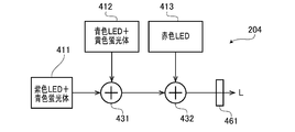
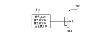
- FIG. 10 is a block diagram conceptually showing only the light source unit, the dichroic mirror, and the wavelength limiting filter in the light source device 204 according to the fourth embodiment of the present invention. Similarly to the light source device 201 according to the first embodiment, the light source device 204 according to the fourth embodiment is used in the electronic endoscope system 1, for example.
- the light source device 204 includes first to third light source units 411 to 413, first and second dichroic mirrors 431 and 432, and a wavelength limiting filter 461.
- the light source units 411 to 413 are individually controlled to emit light by first to third light source driving circuits (not shown).
- the first light source unit 411 emits light in a purple wavelength band (for example, a wavelength of 395 to 435 nm) and is excited by the purple LED light to emit blue (for example, a wavelength of 430 to 490 nm) fluorescence. It has a blue phosphor that emits light.
- the second light source unit 412 is excited by a blue LED that emits light in a blue wavelength band (for example, a wavelength of 430 to 470 nm) and a blue LED light emitted from the blue LED, and a yellow wavelength band (for example, It has a yellow phosphor that emits fluorescence having a wavelength of 500 to 720 nm.
- the third light source unit 413 is a red LED that emits light in a red wavelength band (for example, a wavelength of 620 to 680 nm).
- a collimator lens (not shown) is arranged in front of each of the light source units 411 to 413 in the emission direction. Purple LED light and blue fluorescence emitted from the first light source unit 411 are converted into parallel light by a collimating lens and are incident on a dichroic mirror 431. Further, the blue LED light and the yellow fluorescence emitted from the second light source unit 412 are converted into parallel light by the collimator lens and are incident on the dichroic mirror 431.
- the dichroic mirror 431 combines the optical path of the light emitted from the first light source unit 411 and the optical path of the light emitted from the second light source unit 412. The light whose optical path is synthesized by the dichroic mirror 431 enters the dichroic mirror 432.
- the red LED light emitted from the third light source unit 413 is converted into parallel light by the collimating lens and is incident on the dichroic mirror 432.
- the dichroic mirror 432 combines the optical path of the light incident from the dichroic mirror 431 and the optical path of the light emitted from the third light source unit 413.
- the light whose optical path is synthesized by the dichroic mirror 432 is emitted as irradiation light L toward the wavelength limiting filter 461.
- the spectral transmission characteristic of the wavelength limiting filter 461 is the same as the spectral transmission characteristic of the wavelength limiting filter 161 of the first embodiment.
- the wavelength limiting filter 461 is removed from the optical path of the irradiation light L.
- the irradiation light L is emitted from the light source device 204 without being limited in wavelength by the wavelength limiting filter 461.
- the wavelength limiting filter 461 is inserted in the optical path of the irradiation light L. In this case, of the irradiation light L, only light having a wavelength near 415 nm and a wavelength near 550 nm is emitted from the light source device 204.
- FIG. 11 is a view similar to FIG. 5 and shows the spectral intensity distribution of the irradiation light L emitted from the light source device 204 in each observation mode.
- FIG. 11B also shows the spectral transmission characteristic T461 of the wavelength limiting filter 461.
- the first to third light source units 411 to 413 are all driven to emit light.
- the wavelength limiting filter 461 is removed from the optical path of the irradiation light L.
- the spectral intensity distribution D411 of the first light source unit 411 has peaks at wavelengths of about 415 nm and 470 nm. These two wavelengths are the peak wavelengths of purple LED light and blue fluorescence, respectively.
- the height of the peak at the wavelength of about 415 nm is set to be higher than the height of the peak at the wavelength of about 470 nm.
- the spectral intensity distribution D412 of the second light source unit 412 has peaks at about 450 nm and 600 nm. These two wavelengths are the peak wavelengths of blue LED light and yellow fluorescence, respectively.
- the spectral intensity distribution D413 of the third light source unit 413 has a steep intensity distribution having a peak wavelength of about 650 nm.
- the cutoff wavelengths ⁇ 431 and ⁇ 432 of the dichroic mirrors 431 and 432 are indicated by dotted lines. Cutoff wavelengths ⁇ 431 and ⁇ 432 are 520 nm and 630 nm, respectively. Any of the dichroic mirrors 431 and 432 transmits light having a wavelength band shorter than the cutoff wavelength, and reflects light having a wavelength band equal to or greater than the cutoff wavelength. By the dichroic mirrors 431 and 432, the optical paths of the light emitted from the light source units 411 to 413 are combined.
- the blue LED light having a peak wavelength of about 450 nm is shorter than the cutoff wavelength ⁇ 431, and thus is included in the light whose optical path is synthesized by the dichroic mirror 431. I can't.
- the light paths emitted from the respective light source units 411 to 413 are synthesized by the dichroic mirrors 431 and 432, so that the light source device 204 can emit light from the ultraviolet region (part of near ultraviolet) to the red region.
- Irradiation light L (normal light) having a wide wavelength band is emitted.
- the spectral intensity distribution of the irradiation light L (normal light) is the sum of the areas indicated by the solid lines in the spectral intensity distributions D411 to D413 shown in FIG.
- the first light source unit 411 and the second light source unit 412 are driven to emit light, and the third light source unit 413 is not driven to emit light.
- the wavelength limiting filter 461 is inserted on the optical path of the irradiation light L.
- the biological tissue in the body cavity imaged by the electronic endoscope system 1 is generally reddish due to blood.
- red light when red light is irradiated onto the living tissue in the special observation mode, the entire captured image is reddish, and it is difficult to obtain an effect of enhancing the superficial blood vessels.
- the red LED third light source unit 413 is not driven to emit light in the special observation mode, it is possible to prevent the enhancement effect of the superficial blood vessels from being reduced.
- the second light source unit 412 has a yellow phosphor, but the present invention is not limited to this.
- the second light source unit 412 may include a green phosphor having a peak wavelength near 550 nm, instead of the yellow phosphor.
- an endoscope light source device according to a fifth embodiment of the present invention will be described.
- the light source device according to the fifth embodiment is also used in the electronic endoscope system 1 in the same manner as the light source device 201 according to the first embodiment.
- FIG. 12 is a block diagram conceptually showing only a light source unit, a dichroic mirror, and a wavelength limiting filter in the light source device 205 according to the fifth embodiment.
- the light source device 205 includes a first light source unit 511, a second light source unit 512, a dichroic mirror 531, and a wavelength limiting filter 561.
- the light source units 511 and 512 are individually controlled to emit light by first and second light source driving circuits (not shown).
- the first light source unit 511 has a purple LED that emits light in a purple wavelength band (for example, a wavelength of 395 to 435 nm), and a green phosphor and a blue phosphor that are mounted on the light emitting surface of the purple LED. ing.
- the green phosphor is excited by the purple LED light emitted from the purple LED, and emits fluorescence in the green wavelength band (for example, the wavelength is 510 to 630 nm).
- the blue phosphor is excited by the violet LED light emitted from the violet LED, and emits fluorescence in a blue wavelength band (for example, the wavelength is 430 to 550 nm).
- the second light source unit 512 is a red LED that emits light in a red wavelength band (for example, a wavelength of 620 to 680 nm).
- the dichroic mirror 531 combines the optical path of the light emitted from the first light source unit 511 and the optical path of the light emitted from the second light source unit 512.
- the light whose optical path is synthesized by the dichroic mirror 531 is emitted toward the wavelength limiting filter 561 as the irradiation light L.
- the spectral transmission characteristic of the wavelength limiting filter 561 is the same as the spectral transmission characteristic of the wavelength limiting filter 161 of the first embodiment.
- the wavelength limiting filter 561 is removed from the optical path of the irradiation light L. In this case, the irradiation light L is emitted from the light source device 205 without the wavelength being limited by the wavelength limiting filter 561.
- the wavelength limiting filter 561 is inserted in the optical path of the irradiation light L. In this case, of the irradiation light L, only light having a wavelength near 415 nm and a wavelength near 550 nm is emitted from the light source device 205.
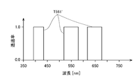
- FIG. 13 is a view similar to FIG. 5 and shows the spectral intensity distribution of the irradiation light L emitted from the light source device 205 in each observation mode.
- FIG. 13B also shows the spectral transmission characteristic T561 of the wavelength limiting filter 561.
- the first and second light source units 511 and 512 are driven to emit light.
- the wavelength limiting filter 561 is removed from the optical path of the irradiation light L.
- the spectral intensity distribution D511 of light emitted from the first light source unit 511 has peaks at wavelengths of about 415 nm, about 470 nm, and about 550 nm. These three wavelengths are respectively the peak wavelengths of the purple LED light emitted from the purple LED, the fluorescence emitted by the blue phosphor, and the fluorescence emitted by the green phosphor.
- the spectral intensity distribution D512 of light emitted from the second light source unit 512 has an intensity distribution with a peak wavelength of about 650 nm.
- the cutoff wavelength ⁇ 531 of the dichroic mirror 531 is indicated by a dotted line.
- the cutoff wavelength ⁇ 531 is 620 nm.
- the dichroic mirror 531 transmits light in a wavelength band shorter than the cutoff wavelength, and reflects light in a wavelength band equal to or greater than the cutoff wavelength.
- the optical paths of the light emitted from the first light source unit 511 and the second light source unit 512 are combined and emitted as irradiation light L.
- irradiation light L normal light
- the electronic endoscope system 1 when the electronic endoscope system 1 is in the special observation mode, only the first light source unit 511 is driven to emit light, and the second light source unit 512 is not driven to emit light. At this time, the wavelength limiting filter 561 is inserted on the optical path of the irradiation light L. As a result, the ratio of light in the vicinity of a wavelength of 415 nm, which is the peak of the absorbance of hemoglobin, in the irradiation light L (special light) is relatively high (that is, narrow-band light), and a captured image in which the surface blood vessels are emphasized is obtained. Obtainable.
- the light source unit 611 includes a purple LED, a blue phosphor, a green phosphor, and a red phosphor that emit light in a purple wavelength band (for example, a wavelength of 395 to 435 nm).
- the blue phosphor is excited by the violet LED light emitted from the violet LED, and emits fluorescence in a blue wavelength band (for example, the wavelength is 430 to 550 nm).
- the green phosphor is excited by the purple LED light emitted from the purple LED, and emits fluorescence in the green wavelength band (for example, the wavelength is 510 to 630 nm).
- the red phosphor is excited by the violet LED light emitted from the violet LED, and emits fluorescence in a red wavelength band (for example, the wavelength is 550 to 750 nm).
- the light emitted from the light source unit 611 is emitted toward the wavelength limiting filter 661 as the irradiation light L.
- the spectral transmission characteristic of the wavelength limiting filter 661 is the same as the spectral transmission characteristic of the wavelength limiting filter 161 of the first embodiment.
- the wavelength limiting filter 661 is removed from the optical path of the irradiation light L.
- the irradiation light L is emitted from the light source device 206 without being limited in wavelength by the wavelength limiting filter 661.
- the wavelength limiting filter 661 is inserted into the optical path of the irradiation light L. In this case, of the irradiation light L, only light having a wavelength near 415 nm and a wavelength near 550 nm is emitted from the light source device 205.
- FIG. 15 is a view similar to FIG. 5 and shows the spectral intensity distribution of the irradiation light L emitted from the light source device 206 in each observation mode.
- FIG. 15B also shows the spectral transmission characteristic T661 of the wavelength limiting filter 661.
- the light source unit 611 is driven to emit light after the wavelength limiting filter 661 is removed from the optical path of the irradiation light L.
- the spectral intensity distribution D611 of light emitted from the light source unit 611 has peaks at wavelengths of about 415 nm, about 470 nm, about 550 nm, and about 650 nm. These four wavelengths are the peak wavelengths of the purple LED light emitted from the purple LED, the fluorescence emitted by the blue phosphor, the fluorescence emitted by the green phosphor, and the fluorescence emitted by the red phosphor.
- the light emitted from the light source unit 611 is irradiated to the subject as irradiation light L (normal light). Thereby, a normal color photographed image can be obtained.
- the light source unit 611 is driven to emit light after the wavelength limiting filter 661 is inserted in the optical path of the irradiation light L.
- the ratio of light in the vicinity of a wavelength of 415 nm, which is the peak of the absorbance of hemoglobin, in the irradiation light L (special light) is relatively high (that is, narrow-band light), and a captured image in which the surface blood vessels are emphasized is obtained.
- Embodiments of the present invention are not limited to those described above, and various modifications are possible within the scope of the technical idea of the present invention.
- the embodiment of the present invention also includes contents appropriately combined with embodiments or the like clearly shown in the specification or obvious embodiments.
- an LED is assumed as the solid state light emitting device.
- the present invention is not limited to this, and it is also possible to employ LD (Laser Diode) as a solid state light emitting device.
- FIG. 16 shows spectral transmission characteristics of the wavelength limiting filter according to the modification of the third embodiment.
- two wavelength limiting filters (wavelength limiting filters 361A and 361B) are provided.
- FIG. 16A shows the spectral transmission characteristic T361A of the wavelength limiting filter 361A
- FIG. 16B shows the spectral transmission characteristic T361B of the wavelength limiting filter 361B.
- the wavelength limiting filter 361A has a transmittance of about 1 (100%) for light in the vicinity of a wavelength of 415 nm (more specifically, 390 nm to 430 nm), and other wavelength bands.
- the transmittance for light is approximately 0 (0%).
- the wavelength limiting filter 361B has a transmittance of about 1 (100%) for light in the vicinity of a wavelength of 550 nm (more specifically, 520 nm to 580 nm), and other wavelength bands.
- the transmittance for light is approximately 0 (0%).
- the wavelength limiting filters 361A and 361B are supported so as to be insertable / removable with respect to the optical path of the irradiation light L by an insertion / extraction mechanism similar to the filter insertion / extraction mechanism 171.
- there are three observation modes normal observation mode, first special observation mode, and second special observation mode).
- the wavelength limiting filter 361A is inserted into the optical path of the irradiation light L, and the wavelength limiting filter 361B is not inserted into the optical path of the irradiation light L. In this case, only the light having a wavelength of about 415 nm out of the irradiation light L is emitted from the light source device 203.
- the wavelength limiting filter 361B is inserted into the optical path of the irradiation light L, and the wavelength limiting filter 361A is not inserted into the optical path of the irradiation light L. In this case, only the light having a wavelength of around 550 nm out of the irradiation light L is emitted from the light source device 203.
- FIG. 17 is a view similar to FIG. 5 and shows the spectral intensity distribution of the irradiation light L emitted from the light source device 203 in each observation mode of this modification.
- FIG. 17A shows the spectral intensity distribution of the irradiation light L (normal light) in the normal observation mode
- FIG. 17B shows the spectral intensity distribution of the irradiation light L (special light) in the first special observation mode
- FIG. 17C shows the spectral intensity distribution of the irradiation light L (special light) in the second special observation mode.
- FIGS. 17B and 17C also show the spectral transmission characteristic T361A of the wavelength limiting filter 361A and the spectral transmission characteristic T361B of the wavelength limiting filter 361B, respectively.
- the operation in the normal observation mode is the same as that of the third embodiment described with reference to FIGS. Therefore, in the normal observation mode, the irradiation light L (normal light) having the same spectral characteristics as in FIG. 9A, that is, the irradiation light L having a wide wavelength band from the ultraviolet region (part of the near ultraviolet) to the red region. It is injected. By irradiating the subject with the irradiation light L (normal light), a normal color photographed image can be obtained.
- both the first light source unit 311 and the second light source unit 312 are driven to emit light after the red phosphor 312b is removed from the optical path.
- the wavelength limiting filter 361A is inserted on the optical path of the irradiation light L, and the wavelength limiting filter 361B is extracted on the optical path of the irradiation light L.
- the intensity in the vicinity of the wavelength of 415 nm which is the absorption peak of hemogbin, is relatively higher than the intensity in other wavelength bands in the irradiation light L (special light). (That is, narrowband light having a peak only in the vicinity of a wavelength of 415 nm), and a captured image in which the surface blood vessels are emphasized can be obtained.
- the red phosphor 312b is removed from the optical path, and both the first light source unit 311 and the second light source unit 312 are driven to emit light.
- the wavelength limiting filter 361B is inserted on the optical path of the irradiation light L, and the wavelength limiting filter 361A is extracted on the optical path of the irradiation light L.
- the intensity around the wavelength of 550 nm which is the absorption peak of hemogbin, is relatively higher than the intensity in other wavelength bands in the irradiation light L (special light). (That is, narrowband light having a peak only in the vicinity of a wavelength of 550 nm), and a captured image in which the middle blood vessel is emphasized can be obtained.
- the present modification it is possible to obtain a photographed image that mainly emphasizes the surface blood vessels in the first special observation mode, and obtain a photographed image that mainly emphasizes the middle-layer blood vessels in the second special observation mode. Can do. That is, in this modification, by switching between the first special observation mode and the second special observation mode, blood vessels in a desired layer region (surface layer in the first special observation mode and middle layer in the second special observation mode) are focused. It is possible to observe an image that has been emphasized.
- FIG. 18 shows the spectral transmission characteristic T561 'of the wavelength limiting filter 561' according to the modification of the fifth embodiment.
- the wavelength limiting filter 561 ′ according to this modification includes a wavelength near 415 nm (more specifically, 390 nm to 430 nm), a wavelength near 550 nm (more specifically, 520 nm to 580 nm), and a wavelength near 650 nm ( More specifically, the transmittance with respect to light of 620 nm to 680 nm is approximately 1 (100%), and the transmittance with respect to light in other wavelength bands is approximately 0 (0%).
- the wavelength limiting filter 561 ' is removed from the optical path of the irradiation light L.
- the irradiation light L is emitted from the light source device 205 without being limited in wavelength by the wavelength limiting filter 561 ′.
- the wavelength limiting filter 561 ' is inserted in the optical path of the irradiation light L.
- the irradiation light L only light having a wavelength of about 415 nm, a wavelength of about 550 nm, and a wavelength of about 650 nm is emitted from the light source device 205.
- FIG. 19 is a view similar to FIG. 5 and shows the spectral intensity distribution of the irradiation light L emitted from the light source device 205 in each observation mode of this modification.
- FIG. 19B also shows the spectral transmission characteristic T561 'of the wavelength limiting filter 561'.
- irradiation light L normal light
- irradiation light L normal light
- a normal color photographed image can be obtained.
- the first and second light source units 511 and 512 are driven to emit light.
- the wavelength limiting filter 561 is inserted on the optical path of the irradiation light L.
- the ratio of light in the vicinity of wavelengths of 415 nm and 650 nm, which is the absorption peak of hemoglobin, of the irradiation light L (special light) is relatively high (that is, narrow-band light), and mainly the superficial blood vessels and deep layers. A captured image in which blood vessels are emphasized can be obtained.
- a configuration in which a narrow-band observation image in which a blood vessel is emphasized using special light (narrow-band light) is generated and displayed is employed.
- a configuration is adopted in which biological information (specifically, oxygen saturation) of a subject is quantitatively analyzed and imaged based on a plurality of images taken with light having different wavelength ranges. Also good.
- FIG. 20 shows a block diagram of a light source device 207 according to another embodiment. Another embodiment will be described based on the second embodiment for convenience.
- the light source device 207 has a configuration in which the wavelength limiting filter 261 is replaced with a rotary turret 400 and a filter rotating mechanism 430 is added to the light source device 202 according to the second embodiment.
- the rotary turret 400 is supported by a filter insertion / extraction mechanism 171 so as to be insertable / removable with respect to the optical path of the irradiation light L.
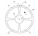
- FIG. 21 is a diagram showing a configuration of the rotary turret 400.
- a motor shaft 432 of a DC motor constituting the filter rotation mechanism 430 is press-fitted into the bearing hole formed at the center of the rotary turret 400.
- the rotary turret 400 is supported by a filter rotating mechanism 430 so as to be rotatable around a motor shaft 432.
- the filter rotation mechanism 430 since a well-known structure is employ
- the rotary turret 400 has four openings arranged in the circumferential direction. Each aperture is provided with a filter having a different spectral characteristic. Specifically, a wavelength limiting filter 261 ', a first oxygen saturation observation filter Fs1, a second oxygen saturation observation filter Fs2, and a narrow band observation filter Fs3 are arranged. In another embodiment, by using the rotary turret 400, in addition to the normal observation image in the normal observation mode and the narrow band observation image in the special observation mode, the oxygen saturation distribution image in the oxygen saturation observation mode is displayed. Is possible.
- FIG. 22 shows an absorption spectrum of hemoglobin near 550 nm.
- Hemoglobin has a strong absorption band called a Q band derived from porphyrin near 550 nm.
- the absorption spectrum of hemoglobin varies depending on the oxygen saturation (the ratio of oxygenated hemoglobin in the total hemoglobin).
- the solid line waveform in FIG. 22 shows an absorption spectrum when the oxygen saturation is 100% (that is, oxygenated hemoglobin HbO), and the long broken line waveform is when the oxygen saturation is 0% (that is, reduction).
- the absorption spectrum of hemoglobin Hb is shown.
- the short dashed line shows the absorption spectrum of hemoglobin (a mixture of oxygenated hemoglobin and reduced hemoglobin) at intermediate oxygen saturation (10, 20, 30,... 90%).
- oxygenated hemoglobin and reduced hemoglobin have different peak wavelengths. Specifically, oxygenated hemoglobin has an absorption peak P1 near a wavelength of 542 nm and an absorption peak P3 near a wavelength of 578 nm. On the other hand, reduced hemoglobin has an absorption peak P2 near 558 nm.
- FIG. 22 shows a two-component absorption spectrum in which the sum of the concentrations of the components (oxygenated hemoglobin and deoxyhemoglobin) is constant. Therefore, the absorption is constant regardless of the concentration of each component (that is, oxygen saturation). Iso-absorption points E1, E2, E3, E4 appear.
- wavelength region sandwiched between the equal absorption points E1 and E2 is referred to as “wavelength region R1”
- the wavelength region sandwiched between the equal absorption points E2 and E3 is referred to as “wavelength region R2”
- wavelength region R3 A wavelength region sandwiched between the absorption points E3 and E4 is referred to as a “wavelength region R3”.
- a wavelength region sandwiched between the isosbestic points E1 and E4 (that is, a combination of the wavelength regions R1, R2, and R3) is referred to as a “wavelength region R0”.
- the wavelength range R0 is 528 nm to 584 nm.
- the wavelength range R2 is 546 nm to 570 nm.
- the absorption monotonously increases or decreases with respect to the oxygen saturation between adjacent isosbestic points. Further, between adjacent isosbestic points, the absorption of hemoglobin changes almost linearly with respect to the oxygen saturation.
- the absorption A R1, A R3 of hemoglobin in the wavelength range R1, R3 is linearly and monotonously increases with respect to the concentration of oxygenated hemoglobin (oxygen saturation)
- the oxygen saturation can be calculated from the value of the index X.
- the first oxygen saturation observation filter Fs1 is an optical bandpass filter that selectively transmits light in the 550 nm band. As shown in FIG. 22, the first oxygen saturation observation filter Fs1 transmits light in the wavelength region from the equiabsorption points E1 to E4 (that is, the wavelength region R0) with low loss, and other wavelengths. It has spectral characteristics that shield the light in the area.
- the second oxygen saturation observation filter Fs2 transmits the light in the wavelength region (that is, the wavelength region R2) from the isosbestic points E2 to E3 with low loss and blocks the light in the other wavelength regions. have.
- the wavelength limiting filter 261 ′ has the same spectral transmission characteristics as the wavelength limiting filter 261.
- the narrowband observation filter Fs3 has a spectral transmission characteristic that transmits only light in the 650 nm band (630 to 650 nm) having a high absorbance with respect to a specific living tissue (mainly deep blood vessels).
- the rotary turret 400 has four wavelengths (first oxygen saturation observation filter Fs1, second oxygen saturation observation filter Fs2, narrowband observation filter Fs3, and wavelength limitation filter) that limit the wavelength.
- Four filters 261 ′) are arranged. That is, the rotary turret 400 is provided with a plurality (four) of wavelength limiting filters having different spectral transmission characteristics.
- both the first light source unit 211 and the second light source unit 212 with the rotary turret 400 removed from the optical path of the irradiation light L and the blue phosphor 211b inserted in the optical path. Is driven to emit light. That is, the operation in the normal observation mode is the same as that of the second embodiment described with reference to FIGS. Therefore, in the normal observation mode, irradiation light L (normal light) having the same spectral characteristics as in FIG. 7A is emitted. By irradiating the subject with the irradiation light L (normal light), a normal color photographed image can be obtained.
- the rotary turret 400 is inserted into the optical path of the irradiation light L and the blue phosphor 211b is removed from the optical path, and the first light source unit 211 and the second light source unit 212 are connected. Both are driven to emit light. At this time, the rotary turret 400 stops in a state where the wavelength limiting filter 261 ′ is located on the optical path of the irradiation light L. That is, the operation in the special observation mode is also the same as that in the second embodiment described with reference to FIGS. Therefore, in the special observation mode, the irradiation light L (normal light) having the same spectral characteristics as in FIG. 7B is emitted.
- each of the wavelength limiting filter 261 ′, the first oxygen saturation observation filter Fs1, the second oxygen saturation observation filter Fs2, and the narrowband observation filter Fs3 is irradiated with light L.
- the rotary turret 400 is rotationally driven at a period of one rotation in four frames so that the frames are sequentially inserted into the optical path at a timing synchronized with the frame rate (synchronized with the imaging period).
- a through hole 402 is formed in the rotary turret 400.
- the system controller 21 detects and adjusts the rotational phase of the rotary turret 400 based on the detection timing of the through hole 402 by the photo interrupter 434 constituting the filter rotating mechanism 430. Thereby, the rotary turret 400 is rotationally driven at a constant speed (a period of one rotation in four frames) during the oxygen saturation observation mode.
- the subject is filtered in accordance with the wavelength limiting filter 261 ′, the first oxygen saturation observation filter Fs1, the second oxygen saturation observation filter Fs2, and the narrowband observation filter Fs3.
- Irradiation light L is sequentially irradiated. Therefore, the post-stage signal processing circuit 28 is filtered by the wavelength limiting filter 261 ′, the first oxygen saturation observation filter Fs1, the second oxygen saturation observation filter Fs2, and the narrowband observation filter Fs3.
- the image signals corresponding to the irradiated light L are sequentially input.
- the post-stage signal processing circuit 28 uses the above equation (1) to apply the image signal corresponding to the first oxygen saturation observation filter Fs1 input from the image memory 27 and the second oxygen saturation observation filter Fs2.
- An index X is calculated from the corresponding image signal.
- a non-volatile memory (not shown) provided in the post-stage signal processing circuit 28 stores a numerical table showing a quantitative relationship between the oxygen saturation of hemoglobin and the value of the index X, which are experimentally acquired in advance.
- the post-stage signal processing circuit 28 refers to this numerical table and obtains the oxygen saturation SatO 2 (x, y) corresponding to the value of the index X calculated using the above equation (1).
- the post-stage signal processing circuit 28 uses the data obtained by multiplying the acquired oxygen saturation SatO 2 (x, y) by a predetermined constant as the pixel value of each pixel (x, y) (oxygen saturation distribution image data). ) Is generated.
- the post-stage signal processing circuit 28 generates narrowband observation image data (the image is the same as that in the special observation mode although the rate is reduced) using the image signal corresponding to the wavelength limiting filter 261 ′ input from the image memory 27. To do.
- the post-stage signal processing circuit 28 generates narrowband observation image data using an image signal corresponding to the narrowband observation filter Fs3 input from the image memory 27.
- the post-stage signal processing circuit 28 converts the oxygen saturation distribution image data into a predetermined video format signal.
- the converted video format signal is output to the monitor 300. Thereby, the oxygen saturation distribution image is displayed on the display screen of the monitor 300.
- the irradiation light L from each of the first oxygen saturation observation filter Fs1 and the second oxygen saturation observation filter Fs2 is generated using fluorescence emitted by the green phosphor. Yes.
- the calculation accuracy of the oxygen saturation is improved, a more suitable oxygen saturation distribution image can be obtained to assist the diagnosis of the lesioned part.
- oxygen the irradiation light L from each of the first oxygen saturation observation filter Fs1 and the second oxygen saturation observation filter Fs2 is generated using fluorescence emitted by the yellow phosphor, oxygen The effect of improving the calculation accuracy of the saturation can be obtained.
- the post-stage signal processing circuit 28 may convert the narrowband observation image data into a predetermined video format signal in addition to the oxygen saturation distribution image data.
- a narrow-band observation image is displayed on the display screen of the monitor 300 in addition to the oxygen saturation distribution image.
Abstract
This endoscope light source device is constituted by: a light source unit that is provided with a first solid state light-emitting element and a first and a second fluorescent body, and that projects irradiation light comprising light within a first wavelength band projected from the first solid state light-emitting element, first fluorescent light emitted by the first fluorescent body, and second fluorescent light emitted by the second fluorescent body; at least one wavelength-limiting filter that transmits only light within a specific wavelength band from among the irradiation light; and a filter inserting/removing means that supports the wavelength-limiting filter such that the filter can be inserted and removed with respect to the light path of the irradiation light. When the wavelength-limiting filter is inserted into the light path, the irradiation light is supplied to the endoscope filtered into light which comprises the light in the first wavelength band and the second fluorescent light. When the wavelength-limiting filter is removed from the light path, the irradiation light is supplied to the endoscope without filtering.
Description
本発明は、被写体に光を照射する内視鏡用光源装置及び内視鏡システムに関する。
The present invention relates to an endoscope light source device and an endoscope system for irradiating a subject with light.
照射光の分光強度特性を変化させ、特殊な画像を撮影することが可能な内視鏡システムが知られている。例えば特開2009-165889号公報(以下、「特許文献1」と記す。)に、この種の内視鏡システムに使用される光源装置の具体的構成が記載されている。
An endoscope system that can change the spectral intensity characteristics of irradiated light and take a special image is known. For example, Japanese Unexamined Patent Application Publication No. 2009-165889 (hereinafter referred to as “Patent Document 1”) describes a specific configuration of a light source device used in this type of endoscope system.
特許文献1に記載の内視鏡システムは、キセノンランプと、キセノンランプから射出された照射光の波長帯域を制限する複数の帯域切替フィルタを搭載した光源装置を備えている。帯域切替フィルタは、可視光帯域の光を透過させる通常光観察用フィルタ、赤外領域の光のみを透過させる赤外観察用フィルタ、可視光帯域の光のうち、特定の波長帯域の光を透過させる特殊光観察用フィルタを有している。これらの複数の帯域切替フィルタの1つを照射光の光路に挿入することにより、被写体に照射する照射光の分光強度特性を切り替えることができる。例えば、通常光観察用フィルタを照射光の光路に挿入すると、白色の通常光によって被写体が照明され、通常のカラー撮影画像を得ることができる。また、特殊光観察用フィルタを照射光の光路に挿入すると、生体内の被写体のうち、特定の組織を強調した撮影画像を得ることができる。
The endoscope system described in Patent Document 1 includes a light source device equipped with a xenon lamp and a plurality of band switching filters that limit the wavelength band of irradiation light emitted from the xenon lamp. The band switching filter is a normal light observation filter that transmits light in the visible light band, an infrared observation filter that transmits only light in the infrared region, and transmits light in a specific wavelength band among light in the visible light band. A special light observation filter. By inserting one of the plurality of band switching filters into the optical path of the irradiation light, the spectral intensity characteristic of the irradiation light irradiated on the subject can be switched. For example, when a normal light observation filter is inserted into the optical path of the irradiation light, the subject is illuminated with white normal light, and a normal color photographed image can be obtained. Further, when the special light observation filter is inserted into the optical path of the irradiation light, a photographed image in which a specific tissue is emphasized among subjects in the living body can be obtained.
特許文献1に記載の光源装置では、光源としてキセノンランプを使用している。一方、近年、発光ダイオード(LED:Light Emitting Diode)等の固体発光素子の高輝度化が進んでおり、より寿命の長い固体発光素子を光源として使用したいという需要がある。固体発光素子の波長帯域はキセノンランプに比べて狭い。そこで、例えば、青色のLED光を射出するLEDと黄色の蛍光を発する蛍光体を組み合わせて擬似的な白色光を生成している。しかし、このようにLEDと蛍光体を組み合わせるだけでは、通常光の分光強度分布は可視光帯域でフラットとならず、撮影された被写体の撮影画像の色再現性が悪いという問題がある。
The light source device described in Patent Document 1 uses a xenon lamp as a light source. On the other hand, in recent years, solid-state light-emitting elements such as light-emitting diodes (LEDs: Light Emitting Diodes) have been increasing in brightness, and there is a demand for using a solid-state light-emitting element having a longer life as a light source. The wavelength band of a solid state light emitting device is narrower than that of a xenon lamp. Therefore, for example, pseudo white light is generated by combining an LED emitting blue LED light and a phosphor emitting yellow fluorescence. However, there is a problem that the spectral intensity distribution of normal light does not become flat in the visible light band and the color reproducibility of the photographed image of the photographed subject is poor only by combining the LED and the phosphor in this way.
本発明は上記の事情に鑑みてなされたものであり、その目的とするところは、固体発光素子を光源として使用し、被写体の撮影画像の色再現性を向上可能な内視鏡用光源装置及び内視鏡システムを提供することである。
The present invention has been made in view of the above circumstances, and an object thereof is to use an endoscope light source device that uses a solid light emitting element as a light source and can improve color reproducibility of a photographed image of a subject, and An endoscope system is provided.
本発明の一実施形態に係る内視鏡用光源装置は、第1の固体発光素子、第1及び第2の蛍光体を有し、第1の固体発光素子から射出される第1の波長帯域の光、第1の蛍光体から発せられる第1の蛍光、及び第2の蛍光体から発せられ、第1の蛍光のピーク波長とは異なるピーク波長をもつ第2の蛍光を含む照射光を射出する光源部と、照射光のうち特定の波長帯域の光のみを透過させる少なくとも1つの波長制限フィルタと、波長制限フィルタを、照射光の光路に対して挿抜可能に支持するフィルタ挿抜手段と、を備える。この構成において、フィルタ挿抜手段により波長制限フィルタが照射光の光路に挿入されると、照射光が、第1の波長帯域の光と第2の蛍光を含む光にフィルタリングされて内視鏡に供給される。また、フィルタ挿抜手段により波長制限フィルタが照射光の光路から抜去されると、照射光が波長制限フィルタによってフィルタリングされることなく内視鏡に供給される。
An endoscope light source device according to an embodiment of the present invention includes a first solid-state light emitting element, first and second phosphors, and a first wavelength band emitted from the first solid-state light emitting element. Irradiating light including first light emitted from the first phosphor, first fluorescence emitted from the first phosphor, and second fluorescence emitted from the second phosphor and having a peak wavelength different from the peak wavelength of the first fluorescence A light source unit, at least one wavelength limiting filter that transmits only light in a specific wavelength band of irradiation light, and filter insertion / extraction means that supports the wavelength limitation filter so that the wavelength limitation filter can be inserted into and extracted from the optical path of the irradiation light. Prepare. In this configuration, when the wavelength limiting filter is inserted into the optical path of the irradiation light by the filter insertion / extraction means, the irradiation light is filtered into light including the first wavelength band and the second fluorescence and supplied to the endoscope. Is done. When the wavelength limiting filter is removed from the optical path of the irradiation light by the filter insertion / extraction means, the irradiation light is supplied to the endoscope without being filtered by the wavelength limiting filter.
このような構成によれば、波長制限フィルタを照射光の光路に挿抜することにより、照射光を、可視光帯域において広い波長帯域を有する通常光と、通常光と比較して狭い波長帯域を有する特殊光との間で切り替えることができる。また、内視鏡用光源装置は、第1の固体発光素子と2つの蛍光体を有しているため、通常光の分光強度分布が可視光帯域においてフラットに近づけられる。これにより、色再現性の高い撮影画像を得ることができる。
According to such a configuration, by inserting / removing the wavelength limiting filter into / from the optical path of the irradiation light, the irradiation light has a narrow wavelength band as compared with normal light having a wide wavelength band in the visible light band and normal light. Can switch between special light. In addition, since the endoscope light source device includes the first solid-state light emitting element and the two phosphors, the spectral intensity distribution of normal light can be made flat in the visible light band. Thereby, a captured image with high color reproducibility can be obtained.
また、本発明の一実施形態に係る内視鏡用光源装置は、所定の撮像周期と同期して回転するターレットを更に備える構成としてもよい。この場合、波長制限フィルタは、夫々異なる分光透過特性を持つ複数の波長制限フィルタを含む。また、ターレットには、複数の波長制限フィルタが周方向に並べて配置されている。ターレットが回転することによって照射光の光路に各波長制限フィルタが順に挿入されると、該照射光が、順次、該光路上に挿入された波長制限フィルタに応じてフィルタリングされて内視鏡に供給される。
The endoscope light source device according to an embodiment of the present invention may further include a turret that rotates in synchronization with a predetermined imaging cycle. In this case, the wavelength limiting filter includes a plurality of wavelength limiting filters each having different spectral transmission characteristics. In addition, a plurality of wavelength limiting filters are arranged in the circumferential direction on the turret. When each wavelength limiting filter is sequentially inserted in the optical path of the irradiation light by rotating the turret, the irradiation light is sequentially filtered according to the wavelength limiting filter inserted on the optical path and supplied to the endoscope. Is done.
また、本発明に一実施形態において、光源部は、例えば、第2の固体発光素子を更に有する。この場合、照射光は、第2の固体発光素子から射出される第2の波長帯域の光を更に含む。
In one embodiment of the present invention, the light source unit further includes, for example, a second solid state light emitting element. In this case, the irradiation light further includes light in the second wavelength band emitted from the second solid state light emitting device.
また、本発明に一実施形態において、光源部は、例えば、励起光を射出する励起用固体発光素子を更に有する。この場合、第1の蛍光体は、第1の固体発光素子から射出される第1の波長帯域の光によって励起され、第2の蛍光体は、励起用固体発光素子から射出される励起光によって励起される。
In one embodiment of the present invention, the light source unit further includes, for example, an excitation solid-state light emitting element that emits excitation light. In this case, the first phosphor is excited by light in the first wavelength band emitted from the first solid state light emitting device, and the second phosphor is excited by excitation light emitted from the excitation solid state light emitting device. Excited.
また、本発明に一実施形態において、第1の蛍光体及び第2の蛍光体は、例えば、第1の固体発光素子から射出される第1の波長帯域の光によって励起される。
In one embodiment of the present invention, the first phosphor and the second phosphor are excited by, for example, light in the first wavelength band emitted from the first solid state light emitting device.
また、本発明に一実施形態において、第1の蛍光体及び第2の蛍光体は、例えば、第2の固体発光素子から射出される第2の波長帯域の光によって励起される。
Also, in one embodiment of the present invention, the first phosphor and the second phosphor are excited by, for example, light in the second wavelength band emitted from the second solid state light emitting device.
また、本発明に一実施形態において、光源部は、例えば、第1の蛍光のピーク波長及び第2の蛍光のピーク波長とは異なるピーク波長をもつ第3の蛍光を発する第3の蛍光体を更に有する。この場合、照射光は、第3の蛍光を更に含む。
In one embodiment of the present invention, the light source unit includes, for example, a third phosphor that emits third fluorescence having a peak wavelength different from the peak wavelength of the first fluorescence and the peak wavelength of the second fluorescence. Also have. In this case, the irradiation light further includes third fluorescence.
また、本発明に一実施形態において、光源部は、例えば、第1の固体発光素子と第1の蛍光体を有する第1の光源ユニットと、第2の蛍光体を有する第2の光源ユニットと、第1の光源ユニットから射出された光の光路と第2の光源ユニットから射出された光の光路を合成することにより、照射光を内視鏡に供給する光路合成手段と、を更に備える。
In one embodiment of the present invention, the light source unit includes, for example, a first light source unit having a first solid state light emitting element and a first phosphor, and a second light source unit having a second phosphor. And an optical path combining means for combining the optical path of the light emitted from the first light source unit and the optical path of the light emitted from the second light source unit to supply the irradiation light to the endoscope.
また、本発明に一実施形態において、第1の光源ユニットは、例えば、第1の蛍光体を第1の固体発光素子から射出される光の光路に対して挿抜可能に支持する蛍光体挿抜手段を更に有する。この場合、フィルタ挿抜手段により波長制限フィルタが照射光の光路に挿入されると、蛍光体挿抜手段は第1の蛍光体を第1の固体発光素子から射出される光の光路から抜去し、フィルタ挿抜手段により波長制限フィルタが照射光の光路から抜去されると、蛍光体挿抜手段は第1の蛍光体を第1の固体発光素子から射出される光の光路に挿入する。
In one embodiment of the present invention, the first light source unit includes, for example, a phosphor inserting / removing unit that supports the first phosphor so that the first phosphor can be inserted into and removed from the optical path of light emitted from the first solid state light emitting device. It has further. In this case, when the wavelength limiting filter is inserted into the optical path of the irradiation light by the filter insertion / extraction means, the phosphor insertion / extraction means extracts the first phosphor from the optical path of the light emitted from the first solid state light emitting device, and the filter When the wavelength limiting filter is removed from the optical path of the irradiation light by the insertion / extraction means, the phosphor insertion / extraction means inserts the first phosphor into the optical path of the light emitted from the first solid state light emitting device.
また、本発明に一実施形態に係る内視鏡システムは、上記の内視鏡用光源装置と内視鏡とを備える。
In addition, an endoscope system according to an embodiment of the present invention includes the above-described endoscope light source device and an endoscope.
本発明の一実施形態によれば、固体発光素子を光源として使用し、被写体の撮影画像の色再現性を向上可能な内視鏡用光源装置及び内視鏡システムが提供される。
According to an embodiment of the present invention, there are provided an endoscope light source device and an endoscope system that use a solid light emitting element as a light source and can improve the color reproducibility of a photographed image of a subject.
以下、本発明の実施形態について図面を参照しながら説明する。なお、以下においては、本発明の一実施形態として内視鏡用光源装置を備える電子内視鏡システムを例に取り説明する。
Hereinafter, embodiments of the present invention will be described with reference to the drawings. In the following, an electronic endoscope system including an endoscope light source device will be described as an embodiment of the present invention.
(第1の実施形態)
図1は、本発明の第1の実施形態に係る内視鏡用光源装置201を備えた電子内視鏡システム1の構成を示すブロック図である。図1に示されるように、電子内視鏡システム1は、医療用に特化されたシステムであり、電子スコープ100、プロセッサ200及びモニタ300を備えている。 (First embodiment)
FIG. 1 is a block diagram showing a configuration of anelectronic endoscope system 1 including an endoscope light source device 201 according to the first embodiment of the present invention. As shown in FIG. 1, the electronic endoscope system 1 is a system specialized for medical use, and includes an electronic scope 100, a processor 200, and a monitor 300.
図1は、本発明の第1の実施形態に係る内視鏡用光源装置201を備えた電子内視鏡システム1の構成を示すブロック図である。図1に示されるように、電子内視鏡システム1は、医療用に特化されたシステムであり、電子スコープ100、プロセッサ200及びモニタ300を備えている。 (First embodiment)
FIG. 1 is a block diagram showing a configuration of an
プロセッサ200は、システムコントローラ21及びタイミングコントローラ22を備えている。システムコントローラ21は、メモリ23に記憶された各種プログラムを実行し、電子内視鏡システム1全体を統合的に制御する。また、システムコントローラ21は、操作パネル24に接続されている。システムコントローラ21は、操作パネル24より入力される術者からの指示に応じて、電子内視鏡システム1の各動作及び各動作のためのパラメータを変更する。術者による入力指示には、例えば電子内視鏡システム1の観察モードの切替指示がある。観察モードには、通常観察モード、特殊観察モードがある。各観察モードについての詳細は後述する。タイミングコントローラ22は、各部の動作のタイミングを調整するクロックパルスを電子内視鏡システム1内の各回路に出力する。
The processor 200 includes a system controller 21 and a timing controller 22. The system controller 21 executes various programs stored in the memory 23 and controls the entire electronic endoscope system 1 in an integrated manner. The system controller 21 is connected to the operation panel 24. The system controller 21 changes each operation of the electronic endoscope system 1 and parameters for each operation in accordance with an instruction from the operator input from the operation panel 24. The input instruction by the operator includes, for example, an instruction to switch the observation mode of the electronic endoscope system 1. The observation mode includes a normal observation mode and a special observation mode. Details of each observation mode will be described later. The timing controller 22 outputs a clock pulse for adjusting the operation timing of each unit to each circuit in the electronic endoscope system 1.
プロセッサ200は、光源装置201を備えている。図2に、本発明の第1の実施形態に係る光源装置201のブロック図を示す。光源装置201は、第1の光源ユニット111及び第2の光源ユニット112を備えている。第1、第2の光源ユニット111、112はそれぞれ、第1、第2光源駆動回路141、142によって個別に発光制御される。
The processor 200 includes a light source device 201. FIG. 2 is a block diagram of the light source device 201 according to the first embodiment of the present invention. The light source device 201 includes a first light source unit 111 and a second light source unit 112. The first and second light source units 111 and 112 are individually controlled to emit light by the first and second light source drive circuits 141 and 142, respectively.
本実施形態では、光源装置201がプロセッサ200内に備えられているが、別の実施形態では、光源装置201は、プロセッサ200(より正確には、画像処理装置を構成する部分)と別体の装置であってもよい。
In this embodiment, the light source device 201 is provided in the processor 200. However, in another embodiment, the light source device 201 is separate from the processor 200 (more precisely, a part constituting the image processing device). It may be a device.
第1の光源ユニット111は、紫色の波長帯域(例えば、波長が395~435nm)の光を射出する紫色発光ダイオード(LED:Light Emitting Diode)111aと、青色蛍光体111bとを有している。青色蛍光体111bは、紫色LED111aから射出された紫色LED光によって励起され、青色の波長帯域(例えば、波長430~550nm)の蛍光を発する。
The first light source unit 111 includes a purple light emitting diode (LED: Light Emitting Diode) 111a that emits light in a purple wavelength band (for example, a wavelength of 395 to 435 nm) and a blue phosphor 111b. The blue phosphor 111b is excited by the purple LED light emitted from the purple LED 111a and emits fluorescence in a blue wavelength band (for example, a wavelength of 430 to 550 nm).
青色蛍光体111bは、蛍光体挿抜機構151により、光路上に挿抜可能に支持されている。詳しくは、青色蛍光体111bは、観察モードに応じて、紫色LED111aから射出された紫色LED光の光路に挿入又は抜去される。図2に実線で示すように、青色蛍光体111bが紫色LED光の光路上に挿入されている場合、青色蛍光体111bは青色の蛍光を発する。これにより、光源ユニット111からは、紫色LED光と青色の蛍光の両方が射出される。また、図2に点線で示すように、青色蛍光体111bが紫色LED光の光路から抜去されている場合、青色蛍光体111bは励起されず、蛍光を発しない。そのため、光源ユニット111からは、紫色LED光のみが射出される。
The blue phosphor 111b is supported by the phosphor insertion / extraction mechanism 151 so that it can be inserted into and removed from the optical path. Specifically, the blue phosphor 111b is inserted into or removed from the optical path of the purple LED light emitted from the purple LED 111a according to the observation mode. As shown by a solid line in FIG. 2, when the blue phosphor 111b is inserted on the optical path of the purple LED light, the blue phosphor 111b emits blue fluorescence. Thereby, both the purple LED light and the blue fluorescence are emitted from the light source unit 111. Further, as shown by the dotted line in FIG. 2, when the blue phosphor 111b is removed from the optical path of the purple LED light, the blue phosphor 111b is not excited and does not emit fluorescence. Therefore, only the purple LED light is emitted from the light source unit 111.
第2の光源ユニット112は、青色の波長帯域(例えば、波長が420~480nm)の光を射出する青色LED112aと、黄色蛍光体112bとを有している。黄色蛍光体112bは、青色LED112aから射出された青色LED光によって励起され、黄色の波長帯域(例えば、波長が420~700nm)の蛍光を発する。黄色蛍光体112bは青色LED112aの発光面上に取り付けられており、青色蛍光体111bとは異なり、青色LED光の光路上に挿抜可能ではない。
The second light source unit 112 includes a blue LED 112a that emits light in a blue wavelength band (for example, a wavelength of 420 to 480 nm), and a yellow phosphor 112b. The yellow phosphor 112b is excited by the blue LED light emitted from the blue LED 112a, and emits fluorescence in a yellow wavelength band (for example, a wavelength is 420 to 700 nm). The yellow phosphor 112b is attached on the light emitting surface of the blue LED 112a, and unlike the blue phosphor 111b, it cannot be inserted into and removed from the optical path of the blue LED light.
各光源ユニット111、112の光の射出方向の前方にはそれぞれ、コリメートレンズ121、122が配置されている。第1の光源ユニット111から射出された光は、コリメートレンズ121によって平行光に変換され、ダイクロイックミラー131に入射される。また、第2の光源ユニット112から射出された光は、コリメートレンズ122によって平行光に変換され、ダイクロイックミラー131に入射される。ダイクロイックミラー131は、第1の光源ユニット111から射出された光の光路と、第2の光源ユニット112から射出された光の光路とを合成する。詳しくは、ダイクロイックミラー131は、波長520nm付近にカットオフ波長を有しており、カットオフ波長よりも短い波長の光を透過させ、カットオフ波長以上の波長の光を反射する特性を有している。そのため、第1の光源ユニット111から射出された紫色LED光や青色の蛍光はダイクロイックミラー131を透過する。また、第2の光源ユニット112から射出された黄色の蛍光はダイクロイックミラー131で反射される。これにより、第1の光源ユニット111から射出された光と第2の光源ユニット112から射出された光の光路が合成される。ダイクロイックミラー131によって光路が合成された光は、照射光Lとして波長制限フィルタ161に向かって射出される。
Collimating lenses 121 and 122 are arranged in front of the light source units 111 and 112 in the light emission direction, respectively. The light emitted from the first light source unit 111 is converted into parallel light by the collimator lens 121 and is incident on the dichroic mirror 131. The light emitted from the second light source unit 112 is converted into parallel light by the collimator lens 122 and is incident on the dichroic mirror 131. The dichroic mirror 131 combines the optical path of the light emitted from the first light source unit 111 and the optical path of the light emitted from the second light source unit 112. Specifically, the dichroic mirror 131 has a cutoff wavelength in the vicinity of a wavelength of 520 nm, transmits light having a wavelength shorter than the cutoff wavelength, and reflects light having a wavelength longer than the cutoff wavelength. Yes. Therefore, the purple LED light and the blue fluorescence emitted from the first light source unit 111 are transmitted through the dichroic mirror 131. Further, the yellow fluorescence emitted from the second light source unit 112 is reflected by the dichroic mirror 131. Thereby, the optical path of the light emitted from the first light source unit 111 and the light emitted from the second light source unit 112 is combined. The light whose optical path is synthesized by the dichroic mirror 131 is emitted as the irradiation light L toward the wavelength limiting filter 161.
波長制限フィルタ161は、特定の波長帯域の光のみを透過させる特性を有する。図3は、波長制限フィルタ161の分光透過特性T161を示している。図3に示されるグラフの横軸は波長(nm)を示し、縦軸は透過率を示している。図3に示すように、波長制限フィルタ161は、波長415nm付近(より詳細には390nm~430nm)及び波長550nm付近(より詳細には520nm~580nm)の光に対する透過率は略1(100%)であり、それ以外の波長帯域の光に対する透過率は略0(0%)である。
The wavelength limiting filter 161 has a characteristic of transmitting only light in a specific wavelength band. FIG. 3 shows the spectral transmission characteristic T161 of the wavelength limiting filter 161. The horizontal axis of the graph shown in FIG. 3 indicates the wavelength (nm), and the vertical axis indicates the transmittance. As shown in FIG. 3, the wavelength limiting filter 161 has a transmittance of about 1 (100%) for light having a wavelength of about 415 nm (more specifically, 390 nm to 430 nm) and a wavelength of about 550 nm (more specifically, 520 nm to 580 nm). The transmittance for light in other wavelength bands is approximately 0 (0%).
波長制限フィルタ161は、フィルタ挿抜機構171によって、照射光Lの光路に対して挿抜可能支持されている。電子内視鏡システム1が通常観察モードである場合、図2に点線で示すように、波長制限フィルタ161は、照射光Lの光路から抜去される。この場合、照射光Lは、波長制限フィルタ161で波長が制限されることなく、光源装置201から射出される。一方、電子内視鏡システム1が特殊観察モードである場合、図2に実線で示すように、波長制限フィルタ161は、照射光Lの光路に挿入される。この場合、照射光Lのうち、波長415nm付近及び波長550nm付近の光のみが光源装置201から射出される。
The wavelength limiting filter 161 is supported by the filter insertion / extraction mechanism 171 so that it can be inserted into and removed from the optical path of the irradiation light L. When the electronic endoscope system 1 is in the normal observation mode, the wavelength limiting filter 161 is removed from the optical path of the irradiation light L as indicated by a dotted line in FIG. In this case, the irradiation light L is emitted from the light source device 201 without being limited in wavelength by the wavelength limiting filter 161. On the other hand, when the electronic endoscope system 1 is in the special observation mode, the wavelength limiting filter 161 is inserted in the optical path of the irradiation light L as indicated by a solid line in FIG. In this case, of the irradiation light L, only light having a wavelength near 415 nm and a wavelength near 550 nm is emitted from the light source device 201.
図4は、光源装置201のうち、各光源ユニット111、112、ダイクロイックミラー131、波長制限フィルタ161のみを概念的に示したブロック図である。青色蛍光体111bは、紫色LED111aとは別体であるため、図4において、青色蛍光体111bと紫色LED111aは、別々のブロックで示されている。一方、黄色蛍光体112bは、青色LED112aの発光面に取り付けられており、青色LED112aと一体に構成されているため、図4において、黄色蛍光体112bと青色LED112aは、一つのブロックで示されている。
FIG. 4 is a block diagram conceptually showing only the light source units 111 and 112, the dichroic mirror 131, and the wavelength limiting filter 161 in the light source device 201. Since the blue phosphor 111b is a separate body from the purple LED 111a, the blue phosphor 111b and the purple LED 111a are shown as separate blocks in FIG. On the other hand, since the yellow phosphor 112b is attached to the light emitting surface of the blue LED 112a and is configured integrally with the blue LED 112a, the yellow phosphor 112b and the blue LED 112a are shown in one block in FIG. Yes.
また、ダイクロイックミラー131は、波長の異なる光の光路を合成するものである。そのため、図4において、ダイクロイックミラー131は、加算記号「+」で示されている。図4において、各光源ユニット111、112の前方に配置されたコリメートレンズ121、122は省略されている。
Further, the dichroic mirror 131 synthesizes optical paths of light having different wavelengths. Therefore, in FIG. 4, the dichroic mirror 131 is indicated by an addition symbol “+”. In FIG. 4, the collimating lenses 121 and 122 disposed in front of the light source units 111 and 112 are omitted.
図4において、各矢印は光の光路を示している。図4に示す例では、第1の光源ユニット111の紫色LED111aから射出された紫色LED光と、青色蛍光体111bが発した青色の蛍光が同一の光路で射出される。また、第2の光源ユニット112の青色LEDから射出された青色LED光と、黄色蛍光体が発した黄色の蛍光が同一の光路で射出される。第1の光源ユニット111から射出された光の光路と第2の光源ユニット112から射出された光の光路は、ダイクロイックミラー131で合成される。ダイクロイックミラー131で光路が合成された光は、光源装置201から、照射光Lとして射出される。
In FIG. 4, each arrow indicates an optical path of light. In the example shown in FIG. 4, the purple LED light emitted from the purple LED 111a of the first light source unit 111 and the blue fluorescence emitted from the blue phosphor 111b are emitted in the same optical path. Further, the blue LED light emitted from the blue LED of the second light source unit 112 and the yellow fluorescence emitted from the yellow phosphor are emitted in the same optical path. The optical path of the light emitted from the first light source unit 111 and the optical path of the light emitted from the second light source unit 112 are combined by the dichroic mirror 131. The light whose optical path is synthesized by the dichroic mirror 131 is emitted as the irradiation light L from the light source device 201.
図1に示すように、光源装置201から射出された照射光Lは、集光レンズ25によりLCB(Light Carrying Bundle)11の入射端面に集光されてLCB11内に入射される。
As shown in FIG. 1, the irradiation light L emitted from the light source device 201 is condensed on the incident end face of the LCB (Light Carrying Bundle) 11 by the condenser lens 25 and enters the LCB 11.
LCB11内に入射された照射光Lは、LCB11内を伝播する。LCB11内を伝播した照射光Lは、電子スコープ100の先端に配置されたLCB11の射出端面から射出され、配光レンズ12を介して被写体に照射される。配光レンズ12からの照射光Lによって照射された被写体からの戻り光は、対物レンズ13を介して固体撮像素子14の受光面上で光学像を結ぶ。
The irradiation light L incident on the LCB 11 propagates in the LCB 11. The irradiation light L propagating through the LCB 11 is emitted from the emission end surface of the LCB 11 disposed at the tip of the electronic scope 100 and is irradiated onto the subject via the light distribution lens 12. The return light from the subject irradiated with the irradiation light L from the light distribution lens 12 forms an optical image on the light receiving surface of the solid-state imaging device 14 via the objective lens 13.
固体撮像素子14は、ベイヤ型画素配置を有する単板式カラーCCD(Charge Coupled Device)イメージセンサである。固体撮像素子14は、受光面上の各画素で結像した光学像を光量に応じた電荷として蓄積して、R(Red)、G(Green)、B(Blue)の画像信号を生成して出力する。なお、固体撮像素子14は、CCDイメージセンサに限らず、CMOS(Complementary Metal Oxide Semiconductor)イメージセンサやその他の種類の撮像装置に置き換えられてもよい。固体撮像素子14はまた、補色系フィルタを搭載したものであってもよい。
The solid-state imaging device 14 is a single-plate color CCD (Charge Coupled Device) image sensor having a Bayer pixel arrangement. The solid-state imaging device 14 accumulates an optical image formed by each pixel on the light receiving surface as a charge corresponding to the amount of light, and generates R (Red), G (Green), and B (Blue) image signals. Output. The solid-state imaging device 14 is not limited to a CCD image sensor, and may be replaced with a CMOS (Complementary Metal Oxide Semiconductor) image sensor or other types of imaging devices. The solid-state image sensor 14 may also be one having a complementary color filter mounted thereon.
電子スコープ100の接続部内には、ドライバ信号処理回路15が備えられている。ドライバ信号処理回路15には、配光レンズ12からの光によって照射された被写体の画像信号がフレーム周期で固体撮像素子14から入力される。フレーム周期は、例えば、1/30秒である。ドライバ信号処理回路15は、固体撮像素子14から入力される画像信号に対して所定の処理を施してプロセッサ200の前段信号処理回路26に出力する。
In the connection part of the electronic scope 100, a driver signal processing circuit 15 is provided. An image signal of a subject irradiated with light from the light distribution lens 12 is input to the driver signal processing circuit 15 from the solid-state imaging device 14 at a frame period. The frame period is, for example, 1/30 seconds. The driver signal processing circuit 15 performs a predetermined process on the image signal input from the solid-state imaging device 14 and outputs the processed image signal to the upstream signal processing circuit 26 of the processor 200.
ドライバ信号処理回路15はまた、メモリ16にアクセスして電子スコープ100の固有情報を読み出す。メモリ16に記録される電子スコープ100の固有情報には、例えば、固体撮像素子14の画素数や感度、動作可能なフレームレート、型番等が含まれる。ドライバ信号処理回路15は、メモリ16から読み出された固有情報をシステムコントローラ21に出力する。
The driver signal processing circuit 15 also accesses the memory 16 and reads the unique information of the electronic scope 100. The unique information of the electronic scope 100 recorded in the memory 16 includes, for example, the number and sensitivity of the solid-state imaging device 14, an operable frame rate, a model number, and the like. The driver signal processing circuit 15 outputs the unique information read from the memory 16 to the system controller 21.
システムコントローラ21は、電子スコープ100の固有情報に基づいて各種演算を行い、制御信号を生成する。システムコントローラ21は、生成された制御信号を用いて、プロセッサ200に接続されている電子スコープ100に適した処理がなされるようにプロセッサ200内の各種回路の動作やタイミングを制御する。
The system controller 21 performs various calculations based on the unique information of the electronic scope 100 and generates a control signal. The system controller 21 uses the generated control signal to control the operation and timing of various circuits in the processor 200 so that processing suitable for the electronic scope 100 connected to the processor 200 is performed.
タイミングコントローラ22は、システムコントローラ21によるタイミング制御に従って、ドライバ信号処理回路15にクロックパルスを供給する。ドライバ信号処理回路15は、タイミングコントローラ22から供給されるクロックパルスに従って、固体撮像素子14をプロセッサ200側で処理される映像のフレームレートに同期したタイミングで駆動制御する。
The timing controller 22 supplies clock pulses to the driver signal processing circuit 15 according to the timing control by the system controller 21. The driver signal processing circuit 15 drives and controls the solid-state imaging device 14 at a timing synchronized with the frame rate of the video processed on the processor 200 side in accordance with the clock pulse supplied from the timing controller 22.
前段信号処理回路26は、ドライバ信号処理回路15から1フレーム周期で入力される画像信号に対してデモザイク処理、マトリックス演算、Y/C分離等の所定の信号処理を施して、画像メモリ27に出力する。
The pre-stage signal processing circuit 26 performs predetermined signal processing such as demosaic processing, matrix calculation, and Y / C separation on the image signal input from the driver signal processing circuit 15 in one frame period, and outputs it to the image memory 27. To do.
画像メモリ27は、前段信号処理回路26から入力される画像信号をバッファし、タイミングコントローラ22によるタイミング制御に従い、後段信号処理回路28に出力する。
The image memory 27 buffers the image signal input from the upstream signal processing circuit 26 and outputs it to the downstream signal processing circuit 28 according to the timing control by the timing controller 22.
後段信号処理回路28は、画像メモリ27から入力される画像信号を処理してモニタ表示用の画面データを生成し、生成されたモニタ表示用の画面データを所定のビデオフォーマット信号に変換する。変換されたビデオフォーマット信号は、モニタ300に出力される。これにより、被写体の画像がモニタ300の表示画面に表示される。
The post-stage signal processing circuit 28 processes the image signal input from the image memory 27 to generate screen data for monitor display, and converts the generated screen data for monitor display into a predetermined video format signal. The converted video format signal is output to the monitor 300. Thereby, the image of the subject is displayed on the display screen of the monitor 300.
本実施形態の電子内視鏡システム1は、通常観察モードと特殊観察モードを含む複数の観察モードを有している。各観察モードは、観察する被写体によって手動又は自動で切り替えられる。例えば、被写体を通常光で照明して観察したい場合は、観察モードが通常観察モードに切り替えられる。なお、通常光は、例えば、白色光や擬似白色光である。白色光は可視光帯域においてフラットな分光強度分布を有する。擬似白色光は、分光強度分布はフラットではなく、複数の波長帯域の光が混色されている。また、例えば、被写体を特殊光で照明することによって特定の生体組織が強調された撮影画像を得たい場合は、観察モードが特殊観察モードに切り替えられる。
The electronic endoscope system 1 of the present embodiment has a plurality of observation modes including a normal observation mode and a special observation mode. Each observation mode is switched manually or automatically depending on the subject to be observed. For example, when it is desired to observe the subject illuminated with normal light, the observation mode is switched to the normal observation mode. The normal light is, for example, white light or pseudo white light. White light has a flat spectral intensity distribution in the visible light band. The pseudo-white light has a spectral intensity distribution that is not flat, and light in a plurality of wavelength bands is mixed. For example, when it is desired to obtain a captured image in which a specific living tissue is emphasized by illuminating the subject with special light, the observation mode is switched to the special observation mode.
なお、特殊光は、例えば、鮮鋭なピークを特定波長に持つ狭帯域光であって、特定の生体組織に対して吸光度の高い光である。特定波長の光には、例えば、表層血管に対して吸光度の高い415nm付近(例えば415±5nm)の光、表層よりも深い中層の血管に対して吸光度の高い550nm付近(例えば550±5nm)の光、中層よりも深い深層の血管に対して吸光度の高い650nm付近(例えば650±5nm)の光が挙げられる。なお、波長の長い光ほど生体組織への深達度が深くなる。そのため、415nm付近、550nm付近、650nm付近の狭帯域光の順に、深達する層域が深くなっている。以下では、特殊観察モードで強調される生体組織が、表層血管である場合について主に説明する。
Note that the special light is, for example, narrow band light having a sharp peak at a specific wavelength, and light having high absorbance with respect to a specific living tissue. For light of a specific wavelength, for example, light having a high absorbance of 415 nm (for example, 415 ± 5 nm) with respect to the surface blood vessel, and light having a high absorbance of 550 nm (for example, 550 ± 5 nm) for the blood vessel in the middle layer deeper than the surface layer. Light and light in the vicinity of 650 nm (for example, 650 ± 5 nm) having a high absorbance with respect to deep blood vessels deeper than the middle layer can be mentioned. Note that the longer the wavelength, the deeper the depth of penetration into the living tissue. For this reason, the layer region that reaches deeper becomes deeper in the order of narrowband light near 415 nm, 550 nm, and 650 nm. Hereinafter, a case where the biological tissue emphasized in the special observation mode is a surface blood vessel will be mainly described.
表層血管内にはヘモグロビンを含む血液が流れている。ヘモグロビンは、波長415nm付近と550nm付近に吸光度のピークを有することが知られている。そのため、被写体に対して表層血管を強調するのに適した特殊光(具体的には、他の波長帯域よりもヘモグロビンの吸光度のピークとなる波長415nm付近の強度が高い光)を照射することにより、表層血管が強調された撮影画像を得ることができる。波長550nm付近の強度が高い特殊光は、表層血管に対しても比較的高い吸光度を持っている。言い換えると、波長550nm付近の強度が高い特殊光も表層血管の強調表示に寄与する。そのため、波長415nm付近の光と共に、ヘモグロビンの吸光度のもう一つのピークとなる波長550nm付近の強度が高い特殊光を照射することにより、表層血管が強調された状態を維持しつつ、撮影画像の輝度を明るくすることができる。
血液 Blood containing hemoglobin flows in the surface blood vessels. It is known that hemoglobin has absorbance peaks near wavelengths of 415 nm and 550 nm. Therefore, by irradiating the subject with special light suitable for emphasizing the superficial blood vessels (specifically, light having a higher intensity near the wavelength of 415 nm where the absorbance of hemoglobin is peak than other wavelength bands). A captured image in which the superficial blood vessels are emphasized can be obtained. Special light having a high intensity near the wavelength of 550 nm has a relatively high absorbance even for the surface blood vessels. In other words, special light having a high intensity in the vicinity of a wavelength of 550 nm also contributes to highlighting of the surface blood vessels. Therefore, by irradiating special light having a high intensity near the wavelength of 550 nm, which is another peak of the absorbance of hemoglobin, together with light near the wavelength of 415 nm, the brightness of the photographed image is maintained while maintaining the state where the surface blood vessels are emphasized. Can be brightened.
すなわち、特殊観察モードでは、特定波長にピークを持つ狭帯域光(特殊光)を用いることにより、通常観察モードでは観察することが難しい血管(表層や中層、深層等の各層域の血管)の走行状態を明瞭に把握するのに適した狭帯域観察を行うことができる。狭帯域観察を行うことにより、癌等の病変の早期発見に有用な情報が得られる。
That is, in special observation mode, by using narrowband light (special light) having a peak at a specific wavelength, blood vessels that are difficult to observe in normal observation mode (blood vessels in each layer such as the surface layer, middle layer, and deep layer) travel. Narrow band observation suitable for clearly grasping the state can be performed. By performing narrow band observation, information useful for early detection of lesions such as cancer can be obtained.
図5は、各観察モードにおいて、光源装置201から射出される照射光Lの分光強度分布を示している。図5(a)は、通常観察モードにおける照射光L(通常光)の分光強度分布を示し、図5(b)は、特殊観察モードにおける照射光L(特殊光)の分光強度分布を示している。図5に示される分光強度分布の横軸は波長(nm)を示し、縦軸は照射光Lの強度を示している。なお、縦軸は、強度の最大値が1となるように規格化されている。
FIG. 5 shows the spectral intensity distribution of the irradiation light L emitted from the light source device 201 in each observation mode. 5A shows a spectral intensity distribution of the irradiation light L (normal light) in the normal observation mode, and FIG. 5B shows a spectral intensity distribution of the irradiation light L (special light) in the special observation mode. Yes. The horizontal axis of the spectral intensity distribution shown in FIG. 5 indicates the wavelength (nm), and the vertical axis indicates the intensity of the irradiation light L. Note that the vertical axis is standardized so that the maximum intensity value is 1.
電子内視鏡システム1が通常観察モードである場合、青色蛍光体111bが光路上に挿入された上で、第1の光源ユニット111及び第2の光源ユニット112が発光駆動される。また、このとき、波長制限フィルタ161は、照射光Lの光路上から抜去される。
When the electronic endoscope system 1 is in the normal observation mode, the first light source unit 111 and the second light source unit 112 are driven to emit light after the blue phosphor 111b is inserted in the optical path. At this time, the wavelength limiting filter 161 is removed from the optical path of the irradiation light L.
第1の光源ユニット111から射出される光の分光強度分布D111は、波長約415nmと波長約470nmにピークを有している。なお本願において、この特定の波長のうち最も強度が高い波長をピーク波長と称する。例えば、強度のピークが2つ以上あった場合には、そのうち最も高い強度を持つ波長をピーク波長という。分光強度分布D111の強度のピークとなる2つの波長はそれぞれ、紫色LED111aから射出される光のピーク波長と、青色蛍光体111bが発する蛍光の分光強度分布のピーク波長である。
The spectral intensity distribution D111 of light emitted from the first light source unit 111 has peaks at a wavelength of about 415 nm and a wavelength of about 470 nm. In the present application, a wavelength having the highest intensity among the specific wavelengths is referred to as a peak wavelength. For example, when there are two or more intensity peaks, the wavelength having the highest intensity is called the peak wavelength. The two wavelengths that are the intensity peaks of the spectral intensity distribution D111 are the peak wavelength of the light emitted from the purple LED 111a and the peak wavelength of the spectral intensity distribution of the fluorescence emitted from the blue phosphor 111b.
第2の光源ユニット112から射出される光の分光強度分布D112は、波長約450nmと波長約600nmにピークを有している。この2つの波長はそれぞれ、青色LED112aから射出される光の分強度分布のピーク波長と、黄色蛍光体112bが発する蛍光の分光強度分布のピーク波長である。
The spectral intensity distribution D112 of light emitted from the second light source unit 112 has peaks at a wavelength of about 450 nm and a wavelength of about 600 nm. These two wavelengths are respectively the peak wavelength of the intensity distribution of the light emitted from the blue LED 112a and the peak wavelength of the spectral intensity distribution of the fluorescence emitted from the yellow phosphor 112b.
なお、図5(a)に示す分光強度分布D111は、紫色LED光と青色の蛍光のピーク強度が略同じであるが、本発明はこれに限定されない。第1の光源ユニット111から射出される紫色LED光と青色の蛍光の強度の比率は、青色蛍光体111bの種類や使用量を変更することによって自由に変更することができる。また、図5(a)に示す分光強度分布D112は、青色LED光と比較して黄色の蛍光の強度の比率が大きいが、本発明はこれに限定されない。第2の光源ユニット112から射出される青色LED光と黄色の蛍光の比率は、黄色蛍光体112bの種類や使用量を変更することによって自由に変更することができる。
The spectral intensity distribution D111 shown in FIG. 5A has substantially the same peak intensity of purple LED light and blue fluorescence, but the present invention is not limited to this. The ratio of the intensity of the purple LED light emitted from the first light source unit 111 to the intensity of blue fluorescence can be freely changed by changing the type and amount of use of the blue phosphor 111b. Further, the spectral intensity distribution D112 shown in FIG. 5A has a larger ratio of the intensity of yellow fluorescence than the blue LED light, but the present invention is not limited to this. The ratio between the blue LED light emitted from the second light source unit 112 and the yellow fluorescence can be freely changed by changing the type and amount of use of the yellow phosphor 112b.
また、図5(a)に示す分光強度分布D111、D112は、強度の最大値が1に揃えられているが、本発明はこれに限定されない。各光源ユニット111、112から射出される光の強度比は、観察する被写体や撮影モード、術者の好みに応じて任意に設定することができる。
In the spectral intensity distributions D111 and D112 shown in FIG. 5A, the maximum intensity is set to 1, but the present invention is not limited to this. The intensity ratio of the light emitted from the light source units 111 and 112 can be arbitrarily set according to the subject to be observed, the photographing mode, and the operator's preference.
また、図5(a)には、ダイクロイックミラー131のカットオフ波長λ131が点線で示されている。ダイクロイックミラー131は、カットオフ波長λ131が約520nmであり、カットオフ波長λ131よりも短い波長帯域の光を透過させ、カットオフ波長λ131以上の波長帯域の光を反射する。そのため、図5(a)に示される分光強度分布D111のうち、実線で示される波長帯域の光がダイクロイックミラー131を透過し、破線で示される波長帯域の光がダイクロイックミラー131で反射される。また、図5(a)に示される分光強度分布D112のうち、実線で示されるカットオフ波長λ131以上の波長帯域の光がダイクロイックミラー131で反射され、破線で示されるカットオフ波長λ131よりも波長帯域の光がダイクロイックミラー131を透過する。
Further, in FIG. 5A, the cutoff wavelength λ 131 of the dichroic mirror 131 is indicated by a dotted line. The dichroic mirror 131 has a cutoff wavelength λ131 of about 520 nm, transmits light in a wavelength band shorter than the cutoff wavelength λ131, and reflects light in a wavelength band longer than the cutoff wavelength λ131. Therefore, in the spectral intensity distribution D111 shown in FIG. 5A, light in the wavelength band indicated by the solid line is transmitted through the dichroic mirror 131, and light in the wavelength band indicated by the broken line is reflected by the dichroic mirror 131. Also, in the spectral intensity distribution D112 shown in FIG. 5A, light in the wavelength band equal to or greater than the cutoff wavelength λ131 indicated by the solid line is reflected by the dichroic mirror 131, and the wavelength is longer than the cutoff wavelength λ131 indicated by the broken line. Band light passes through the dichroic mirror 131.
これにより、ダイクロイックミラー131で、各光源ユニット111、112から射出された光の光路が合成され、光源装置201からは、紫外領域(近紫外の一部)から赤色領域にかけて広い波長帯域を有する照射光L(通常光)が射出される。この照射光L(通常光)の分光強度分布は、図5(a)に示す分光強度分布D111、D112のうち、実線で示される領域を足し合わせたものになる。
As a result, the optical paths of the light emitted from the light source units 111 and 112 are synthesized by the dichroic mirror 131, and the light source device 201 emits light having a wide wavelength band from the ultraviolet region (part of the near ultraviolet) to the red region. Light L (normal light) is emitted. The spectral intensity distribution of the irradiation light L (normal light) is the sum of the areas indicated by the solid lines in the spectral intensity distributions D111 and D112 shown in FIG.
本実施形態では、広い波長帯域を有し、且つ、波長帯域の異なる2つの蛍光体111b、112bを有している。そのため、照射光L(通常光)の分光強度分布は、蛍光体を使用しない場合や、1種類の蛍光体のみを有する場合に比べて、可視光帯域においてフラットに近づく。これにより、自然の白色光に近い照射光L(通常光)で被写体が照明され、色再現性の高いカラー撮影画像を得ることができる。
In the present embodiment, two phosphors 111b and 112b having a wide wavelength band and different wavelength bands are provided. Therefore, the spectral intensity distribution of the irradiation light L (normal light) is closer to flat in the visible light band than when no phosphor is used or when only one type of phosphor is used. Thereby, the subject is illuminated with the irradiation light L (normal light) close to natural white light, and a color photographed image with high color reproducibility can be obtained.
また、電子内視鏡システム1が特殊観察モードである場合、青色蛍光体111bが光路上から抜去された上で、第1の光源ユニット111及び第2の光源ユニット112が発光駆動される。また、このとき、波長制限フィルタ161は、照射光Lの光路上に挿入される。
Further, when the electronic endoscope system 1 is in the special observation mode, the first light source unit 111 and the second light source unit 112 are driven to emit light after the blue phosphor 111b is removed from the optical path. At this time, the wavelength limiting filter 161 is inserted on the optical path of the irradiation light L.
図5(b)には、各光源ユニット111、112から射出される光の強度分布と、波長制限フィルタ161の分光透過特性T161が示されている。光源装置201から照射光L(特殊光)として射出される光は、ダイクロイックミラー131で光路が合成され、且つ、波長制限フィルタ161を透過した光である。そのため、照射光L(特殊光)の分光強度分布は、図5(b)に示す分光強度分布D111、D112のうち、実線で示される領域を足し合わせたものになる。
FIG. 5B shows the intensity distribution of light emitted from the light source units 111 and 112 and the spectral transmission characteristic T161 of the wavelength limiting filter 161. Light emitted from the light source device 201 as irradiation light L (special light) is light whose optical path is combined by the dichroic mirror 131 and transmitted through the wavelength limiting filter 161. Therefore, the spectral intensity distribution of the irradiation light L (special light) is the sum of the areas indicated by the solid lines in the spectral intensity distributions D111 and D112 shown in FIG.
電子内視鏡システム1が特殊観察モードである場合、青色蛍光体111bが光路上から抜去されることにより、紫色LED111aから射出された光が青色蛍光体111bを励起するために使用されないため、ヘモグロビンの吸光度のピークとなる波長415nm付近の光の強度を高くすることができる。また、波長制限フィルタ161により、第2の光源ユニット112から射出される光のうち、ヘモグロビンの吸光度のもう一つのピークとなる波長550nm付近の光のみが被写体に照射される。これにより、表層血管が強調された状態を維持しつつ、撮影画像の輝度を上げることができる。
When the electronic endoscope system 1 is in the special observation mode, since the blue phosphor 111b is removed from the optical path, the light emitted from the purple LED 111a is not used to excite the blue phosphor 111b. It is possible to increase the intensity of light in the vicinity of a wavelength of 415 nm, which is the peak of the absorbance. Also, the wavelength limiting filter 161 irradiates the subject with only light having a wavelength of about 550 nm, which is another peak of hemoglobin absorbance, out of light emitted from the second light source unit 112. Thereby, the brightness | luminance of a picked-up image can be raised, maintaining the state by which the surface blood vessel was emphasized.
また、各光源ユニット111、112から射出された光は、ダイクロイックミラー131によってその光路が合成される。このとき、各光源ユニット111、112から射出される光の波長帯域は互いに異なるため、ダイクロイックミラー131での光路の合成時において、光量の損失を最小限に抑えることができる。
Further, the light paths of the light emitted from the light source units 111 and 112 are combined by the dichroic mirror 131. At this time, since the wavelength bands of the light emitted from the light source units 111 and 112 are different from each other, the loss of the light amount can be minimized when the optical paths in the dichroic mirror 131 are combined.
また、本実施形態では、波長制限フィルタ161を照射光Lの光路上に挿抜することによって、光源装置201から射出される照射光Lの分光強度分布を切り替えている。これにより、プロセッサ200は、所望の照射光Lの分光強度分布に合わせて、複数の光源装置201を有している必要がなく、プロセッサ200の構成の簡素化や小型化が可能である。
In this embodiment, the spectral intensity distribution of the irradiation light L emitted from the light source device 201 is switched by inserting / removing the wavelength limiting filter 161 on the optical path of the irradiation light L. Thereby, the processor 200 does not need to have the plurality of light source devices 201 in accordance with the spectral intensity distribution of the desired irradiation light L, and the configuration of the processor 200 can be simplified and downsized.
なお、電子内視鏡システム1が特殊観察モードである場合、図5(b)に示すように、分光強度分布D111とD112のピーク強度はいずれも1に揃えられているが、本発明はこれに限定されない。例えば、特殊観察モードでは、第2の光源ユニット112は、通常観察モード時よりも、駆動電流を小さくし、強度が低くなるように発光駆動されてもよい。これにより、ヘモグロビンの吸光度のピークとなる波長415nm付近の強度が、他の波長帯域の強度よりも相対的に高くなり(すなわち狭帯域光となり)、より表層血管が強調された撮影画像を得ることができる。
When the electronic endoscope system 1 is in the special observation mode, as shown in FIG. 5 (b), the peak intensities of the spectral intensity distributions D111 and D112 are all set to 1, but the present invention is not limited to this. It is not limited to. For example, in the special observation mode, the second light source unit 112 may be driven to emit light so that the drive current is smaller and the intensity is lower than that in the normal observation mode. As a result, the intensity around the wavelength of 415 nm, which is the peak of hemoglobin absorbance, is relatively higher than the intensity of other wavelength bands (that is, becomes narrowband light), and a captured image in which the surface blood vessels are more emphasized is obtained. Can do.
また、本実施形態では、青色蛍光体111bは、蛍光体挿抜機構151により、光路上に挿抜可能に支持されているが、本発明はこれに限定されない。例えば、青色蛍光体111bは光路上に挿抜可能ではなく、紫色LED111aの発光面上に取り付けられていてもよい。この場合、電子内視鏡システム1が特殊観察モードである場合、第1の光源ユニット111から青色の蛍光も射出される。しかし、この青色の蛍光は波長制限フィルタ161でカットされるため、青色の蛍光によって表層血管の強調効果が低下してしまうことはない。
In the present embodiment, the blue phosphor 111b is supported by the phosphor insertion / extraction mechanism 151 so that it can be inserted into and removed from the optical path. However, the present invention is not limited to this. For example, the blue phosphor 111b is not insertable / removable on the optical path, and may be attached on the light emitting surface of the purple LED 111a. In this case, when the electronic endoscope system 1 is in the special observation mode, blue fluorescence is also emitted from the first light source unit 111. However, since the blue fluorescence is cut by the wavelength limiting filter 161, the enhancement effect of the surface blood vessels is not reduced by the blue fluorescence.
なお、本実施形態において用いられる蛍光体には下記のものが例示として挙げられる。大分類として、酸化物系蛍光体と窒化物系蛍光体が挙げられる。
In addition, the following are mentioned as an example for the fluorescent substance used in this embodiment. As a broad classification, oxide phosphors and nitride phosphors can be mentioned.
《酸化物系蛍光体》
〈黄色蛍光体〉
・Y3Al5O12(イットリウムアルミニウム酸化物)を母体結晶とする黄色蛍光体
〈緑色蛍光体〉
・Ca3Sc2Si3O12(カルシウムスカンジウムケイ素酸化物)を母体結晶としてCeを付活させた緑色蛍光体
・CaSc2O4(カルシウムスカンジウム酸化物)を母体結晶としてCeを付活させた緑色蛍光体 <Oxide-based phosphor>
<Yellow phosphor>
・ Yellow phosphor (green phosphor) having Y 3 Al 5 O 12 (yttrium aluminum oxide) as a base crystal
・ Green phosphor with activated Ca 3 Sc 2 Si 3 O 12 (calcium scandium silicon oxide) as a base crystal ・ Ce activated with CaSc 2 O 4 (calcium scandium oxide) as a base crystal Green phosphor
《窒化物系蛍光体》
〈赤色蛍光体〉
・母体結晶としてEuを付活させたカルシウムアルミニウムケイ素窒化物(CaAlSiN3)にケイ素酸窒化物(Si2N2O)を固溶させた赤色蛍光体
〈その他の蛍光体〉
・母体となるセラミックス結晶に希土類元素等の発光を担う金属イオンを微量添加したサイアロン蛍光体、α型窒化ケイ素(Si3N4)結晶の固溶体であるα-サイアロン蛍光体、窒化カルシウムアルミニウムケイ素(CaAlSiN3)蛍光体など <Nitride phosphor>
<Red phosphor>
・ Red phosphor in which silicon oxynitride (Si 2 N 2 O) is dissolved in calcium aluminum silicon nitride (CaAlSiN 3 ) activated with Eu as a base crystal <other phosphors>
・ Sialon phosphors with a small amount of metal ions responsible for light emission such as rare earth elements added to the base ceramic crystal, α-sialon phosphors that are solid solutions of α-type silicon nitride (Si 3 N 4 ) crystals, calcium aluminum silicon nitride ( CaAlSiN 3 ) phosphor etc.
(第2の実施形態)
次に、本発明の第2の実施形態にかかる内視鏡用光源装置について説明する。第2の実施形態にかかる光源装置も、第1の実施形態にかかる光源装置201と同様に、電子内視鏡システム1において使用される。 (Second Embodiment)
Next, an endoscope light source device according to a second embodiment of the present invention will be described. The light source device according to the second embodiment is also used in theelectronic endoscope system 1 in the same manner as the light source device 201 according to the first embodiment.
次に、本発明の第2の実施形態にかかる内視鏡用光源装置について説明する。第2の実施形態にかかる光源装置も、第1の実施形態にかかる光源装置201と同様に、電子内視鏡システム1において使用される。 (Second Embodiment)
Next, an endoscope light source device according to a second embodiment of the present invention will be described. The light source device according to the second embodiment is also used in the
図6は、第2の実施形態に係る光源装置202のうち、光源ユニット、ダイクロイックミラー、波長制限フィルタのみを概念的に示したブロック図である。光源装置202は、第1の光源ユニット211、第2の光源ユニット212、ダイクロイックミラー231、波長制限フィルタ261を備えている。各光源ユニット211、212はそれぞれ、図示省略された第1光源駆動回路、第2光源駆動回路によって個別に発光制御される。
FIG. 6 is a block diagram conceptually showing only a light source unit, a dichroic mirror, and a wavelength limiting filter in the light source device 202 according to the second embodiment. The light source device 202 includes a first light source unit 211, a second light source unit 212, a dichroic mirror 231, and a wavelength limiting filter 261. The light source units 211 and 212 are individually controlled to emit light by a first light source drive circuit and a second light source drive circuit (not shown).
第1の光源ユニット211は、紫色の波長帯域(例えば、波長が395~435nm)の光を射出する紫色LED211aと、青色蛍光体211bとを有している。青色蛍光体211bは、紫色LED211aから射出された紫色LED光によって励起され、青色の波長帯域(例えば、波長430~550nm)の蛍光を発する。青色蛍光体211bは、不図示の蛍光体挿抜機構により、紫色LED211aから射出された紫色LED光の光路に対して挿抜可能に支持されている。
The first light source unit 211 has a purple LED 211a that emits light in a purple wavelength band (for example, a wavelength of 395 to 435 nm) and a blue phosphor 211b. The blue phosphor 211b is excited by the purple LED light emitted from the purple LED 211a and emits fluorescence in a blue wavelength band (for example, a wavelength of 430 to 550 nm). The blue phosphor 211b is supported by an unillustrated phosphor insertion / extraction mechanism so that the blue phosphor 211b can be inserted into and removed from the optical path of the purple LED light emitted from the purple LED 211a.
第2の光源ユニット212は、青色の波長帯域(例えば、波長が420~480nm)の光を射出する青色LED、緑色蛍光体、赤色蛍光体を有している。緑色蛍光体は、青色LEDから射出された青色LED光によって励起され、緑色の波長帯域(例えば、波長が510~630nm)の蛍光を発する。赤色蛍光体は、青色LEDから射出された青色LED光によって励起され、赤色の波長帯域(例えば、波長が550~750nm)の蛍光を発する。緑色蛍光体と赤色蛍光体は、青色LED光の射出方向に沿って並べて配置されていてもよく、青色LED光の射出方向と垂直な方向に並べて配置されていてもよい。また、緑色蛍光体と赤色蛍光体は、その材料が混ぜ合わせられ、一つの蛍光体として作成されたものであってもよい。
The second light source unit 212 includes a blue LED, a green phosphor, and a red phosphor that emit light in a blue wavelength band (for example, a wavelength of 420 to 480 nm). The green phosphor is excited by blue LED light emitted from the blue LED, and emits fluorescence in a green wavelength band (for example, a wavelength of 510 to 630 nm). The red phosphor is excited by the blue LED light emitted from the blue LED and emits fluorescence in the red wavelength band (for example, the wavelength is 550 to 750 nm). The green phosphor and the red phosphor may be arranged side by side along the emission direction of the blue LED light, or may be arranged side by side in a direction perpendicular to the emission direction of the blue LED light. The green phosphor and the red phosphor may be prepared as a single phosphor by mixing the materials.
各光源ユニット211、212の射出方向の前方にはそれぞれ、図示省略されたコリメートレンズが配置されている。第1の光源ユニット211から射出された光は、コリメートレンズによって平行光に変換され、ダイクロイックミラー231に入射される。また、第2の光源ユニット212から射出された光は、コリメートレンズによって平行光に変換され、ダイクロイックミラー231に入射される。ダイクロイックミラー231は、第1の光源ユニット211から射出された光の光路と第2の光源ユニット212から射出された光の光路を合成する。ダイクロイックミラー231で光路が合成された光は、照射光Lとして波長制限フィルタ261に向かって射出される。波長制限フィルタ261の分光透過特性は、第1の実施形態の波長制限フィルタ161の分光透過特性と同じである。
A collimating lens (not shown) is arranged in front of the light source units 211 and 212 in the emission direction. The light emitted from the first light source unit 211 is converted into parallel light by the collimator lens and is incident on the dichroic mirror 231. The light emitted from the second light source unit 212 is converted into parallel light by the collimator lens and is incident on the dichroic mirror 231. The dichroic mirror 231 combines the optical path of the light emitted from the first light source unit 211 and the optical path of the light emitted from the second light source unit 212. The light whose optical path is synthesized by the dichroic mirror 231 is emitted as the irradiation light L toward the wavelength limiting filter 261. The spectral transmission characteristic of the wavelength limiting filter 261 is the same as the spectral transmission characteristic of the wavelength limiting filter 161 of the first embodiment.
電子内視鏡システム1が通常観察モードである場合、波長制限フィルタ261は、照射光Lの光路から抜去される。この場合、照射光Lは、波長制限フィルタ261で波長が制限されることなく、光源装置202から射出される。一方、電子内視鏡システム1が特殊観察モードである場合、波長制限フィルタ261は、照射光Lの光路に挿入される。この場合、照射光Lのうち、波長415nm付近及び波長550nm付近の光のみが光源装置202から射出される。
When the electronic endoscope system 1 is in the normal observation mode, the wavelength limiting filter 261 is removed from the optical path of the irradiation light L. In this case, the irradiation light L is emitted from the light source device 202 without the wavelength being limited by the wavelength limiting filter 261. On the other hand, when the electronic endoscope system 1 is in the special observation mode, the wavelength limiting filter 261 is inserted in the optical path of the irradiation light L. In this case, of the irradiation light L, only light having a wavelength near 415 nm and a wavelength near 550 nm is emitted from the light source device 202.
図7は、図5と同様の図であり、各観察モードにおいて、光源装置202から射出される照射光Lの分光強度分布を示している。なお、図7(b)には、波長制限フィルタ261の分光透過特性T261も示されている。
FIG. 7 is a view similar to FIG. 5 and shows the spectral intensity distribution of the irradiation light L emitted from the light source device 202 in each observation mode. In FIG. 7B, the spectral transmission characteristic T261 of the wavelength limiting filter 261 is also shown.
電子内視鏡システム1が通常観察モードである場合、青色蛍光体211bが光路上に挿入された上で、第1の光源ユニット211と第2の光源ユニット212の両方が発光駆動される。また、このとき、波長制限フィルタ261は、照射光Lの光路上から抜去される。
When the electronic endoscope system 1 is in the normal observation mode, both the first light source unit 211 and the second light source unit 212 are driven to emit light after the blue phosphor 211b is inserted in the optical path. At this time, the wavelength limiting filter 261 is removed from the optical path of the irradiation light L.
第1の光源ユニット211から射出される光の分光強度分布D211は、波長約415nmと波長約470nmにピークを有している。この2つの波長はそれぞれ、紫色LED211aから射出される光の分強度分布のピーク波長と、青色蛍光体211bが発する蛍光の分光強度分布のピーク波長である。
The spectral intensity distribution D211 of light emitted from the first light source unit 211 has peaks at a wavelength of about 415 nm and a wavelength of about 470 nm. These two wavelengths are the peak wavelength of the intensity distribution of the light emitted from the purple LED 211a and the peak wavelength of the spectral intensity distribution of the fluorescence emitted from the blue phosphor 211b.
第2の光源ユニット212から射出される光の分光強度分布D212は、波長約450nm、約550nm、約650nmにピークを有している。この3つの波長はそれぞれ、青色LED光、緑色蛍光体が発する蛍光、赤色蛍光体が発する蛍光の分強度分布のピーク波長である。
The spectral intensity distribution D212 of light emitted from the second light source unit 212 has peaks at wavelengths of about 450 nm, about 550 nm, and about 650 nm. These three wavelengths are respectively the peak wavelengths of the intensity distribution of the blue LED light, the fluorescence emitted by the green phosphor, and the fluorescence emitted by the red phosphor.
また、図7(a)には、ダイクロイックミラー231のカットオフ波長λ231が点線で示されている。ダイクロイックミラー231は、カットオフ波長λ231が約510nmであり、カットオフ波長λ231よりも短い波長帯域の光を透過させ、カットオフ波長λ231以上の波長帯域の光を反射する。そのため、図7(a)に示される分光強度分布D211のうち、実線で示される波長帯域の光がダイクロイックミラー231を透過し、破線で示される波長帯域の光がダイクロイックミラー231で反射される。また、図7(a)に示される分光強度分布D212のうち、実線で示される波長帯域の光がダイクロイックミラー231で反射され、破線で示される波長帯域の光がダイクロイックミラー231を透過する。
In FIG. 7A, the cutoff wavelength λ231 of the dichroic mirror 231 is indicated by a dotted line. The dichroic mirror 231 has a cutoff wavelength λ231 of about 510 nm, transmits light in a wavelength band shorter than the cutoff wavelength λ231, and reflects light in a wavelength band longer than the cutoff wavelength λ231. Therefore, in the spectral intensity distribution D211 shown in FIG. 7A, light in the wavelength band indicated by the solid line passes through the dichroic mirror 231 and light in the wavelength band indicated by the broken line is reflected by the dichroic mirror 231. In the spectral intensity distribution D212 shown in FIG. 7A, light in the wavelength band indicated by the solid line is reflected by the dichroic mirror 231 and light in the wavelength band indicated by the broken line passes through the dichroic mirror 231.
これにより、ダイクロイックミラー231で、各光源ユニット211、212から射出された光の光路が合成され、光源装置202からは、紫外領域(近紫外の一部)から赤色領域にかけて広い波長帯域を有する照射光L(通常光)が射出される。この照射光L(通常光)の分光強度分布は、図7(a)に示す分光強度分布D211、D212のうち、実線で示される領域を足し合わせたものになる。この照射光L(通常光)を被写体に照射することにより、通常のカラー撮影画像を得ることができる。
Thereby, the optical path of the light emitted from each of the light source units 211 and 212 is synthesized by the dichroic mirror 231, and the light source device 202 emits light having a wide wavelength band from the ultraviolet region (part of near ultraviolet) to the red region. Light L (normal light) is emitted. The spectral intensity distribution of the irradiation light L (normal light) is the sum of the areas indicated by the solid lines in the spectral intensity distributions D211 and D212 shown in FIG. By irradiating the subject with the irradiation light L (normal light), a normal color photographed image can be obtained.
また、電子内視鏡システム1が特殊観察モードである場合、青色蛍光体211bが光路上から抜去された上で、第1の光源ユニット211と第2の光源ユニット212の両方が発光駆動される。また、このとき、波長制限フィルタ261は、照射光Lの光路上に挿入される。これにより、照射光L(特殊光)のうち、ヘモグロビンの吸光度のピークとなる波長415nm付近の光の比率が相対的に高くなり(すなわち狭帯域光となり)、表層血管が強調された撮影画像を得ることができる。
Further, when the electronic endoscope system 1 is in the special observation mode, both the first light source unit 211 and the second light source unit 212 are driven to emit light after the blue phosphor 211b is removed from the optical path. . At this time, the wavelength limiting filter 261 is inserted on the optical path of the irradiation light L. As a result, the ratio of light in the vicinity of a wavelength of 415 nm, which is the peak of the absorbance of hemoglobin, in the irradiation light L (special light) is relatively high (that is, narrow-band light), and a captured image in which the surface blood vessels are emphasized is obtained. Obtainable.
また、第2の光源ユニット212は、緑色と赤色の2つの蛍光体を有している。そのため、電子内視鏡システム1が通常観察モードである場合の照射光L(通常光)の分光強度分布は、第2の光源ユニット212が1つの蛍光体を有している場合よりも、可視領域においてフラットに近づく。これにより、通常観察モードにおいて、自然の白色光に近い照射光L(通常光)で被写体を照明することができる。
The second light source unit 212 has two phosphors, green and red. Therefore, the spectral intensity distribution of the irradiation light L (normal light) when the electronic endoscope system 1 is in the normal observation mode is more visible than when the second light source unit 212 has one phosphor. It approaches flat in the area. Thereby, in the normal observation mode, the subject can be illuminated with the irradiation light L (normal light) close to natural white light.
(第3の実施形態)
次に、本発明の第3の実施形態にかかる内視鏡用光源装置について説明する。第3の実施形態にかかる光源装置も、第1の実施形態にかかる光源装置201と同様に、電子内視鏡システム1において使用される。 (Third embodiment)
Next, an endoscope light source device according to a third embodiment of the present invention will be described. The light source device according to the third embodiment is also used in theelectronic endoscope system 1 in the same manner as the light source device 201 according to the first embodiment.
次に、本発明の第3の実施形態にかかる内視鏡用光源装置について説明する。第3の実施形態にかかる光源装置も、第1の実施形態にかかる光源装置201と同様に、電子内視鏡システム1において使用される。 (Third embodiment)
Next, an endoscope light source device according to a third embodiment of the present invention will be described. The light source device according to the third embodiment is also used in the
図8は、第3の実施形態に係る光源装置203のうち、光源ユニット、ダイクロイックミラー、波長制限フィルタのみを概念的に示したブロック図である。光源装置203は、第1の光源ユニット311、第2の光源ユニット312、ダイクロイックミラー331、波長制限フィルタ361を備えている。各光源ユニット311、312はそれぞれ、図示省略された第1光源駆動回路、第2光源駆動回路によって個別に発光制御される。
FIG. 8 is a block diagram conceptually showing only a light source unit, a dichroic mirror, and a wavelength limiting filter in the light source device 203 according to the third embodiment. The light source device 203 includes a first light source unit 311, a second light source unit 312, a dichroic mirror 331, and a wavelength limiting filter 361. The light source units 311 and 312 are individually controlled to emit light by a first light source drive circuit and a second light source drive circuit (not shown).
第1の光源ユニット311は、紫色の波長帯域(例えば、波長が395~435nm)の光を射出する紫色LEDである。第2の光源ユニット312は、蛍光体LED312aと赤色蛍光体312bとを有している。蛍光体LED312aは、青色の波長帯域(例えば、波長が430~490nm)の光を射出する青色LEDと、青色LEDの発光面上に取り付けられた緑色蛍光体を有している。この緑色蛍光体は、青色LEDから射出された青色LED光によって励起され、緑色の波長帯域(例えば、波長が460~600nm)の蛍光を発する。赤色蛍光体312bは、青色LEDから射出された青色LED光によって励起され、赤色の波長帯域(例えば、波長が550~750nm)の蛍光を発する。赤色蛍光体312bは、不図示の蛍光体挿抜機構により、青色LEDから射出される光の光路に対して挿抜可能に支持されている。
The first light source unit 311 is a purple LED that emits light in a purple wavelength band (for example, a wavelength of 395 to 435 nm). The second light source unit 312 includes a phosphor LED 312a and a red phosphor 312b. The phosphor LED 312a includes a blue LED that emits light in a blue wavelength band (for example, a wavelength of 430 to 490 nm), and a green phosphor that is attached on the light emitting surface of the blue LED. This green phosphor is excited by blue LED light emitted from a blue LED, and emits fluorescence in a green wavelength band (for example, a wavelength of 460 to 600 nm). The red phosphor 312b is excited by the blue LED light emitted from the blue LED, and emits fluorescence in the red wavelength band (for example, the wavelength is 550 to 750 nm). The red phosphor 312b is supported by an unillustrated phosphor insertion / extraction mechanism so that the red phosphor 312b can be inserted into and removed from the optical path of light emitted from the blue LED.
各光源ユニット311、312の射出方向の前方にはそれぞれ、図示省略されたコリメートレンズが配置されている。第1の光源ユニット311から射出された紫色LED光は、コリメートレンズによって平行光に変換され、ダイクロイックミラー331に入射される。また、第2の光源ユニット312から射出された光、すなわち、青色LED光と、緑色及び赤色の蛍光は、コリメートレンズによって平行光に変換され、ダイクロイックミラー331に入射される。ダイクロイックミラー331は、第1の光源ユニット311から射出された光の光路と第2の光源ユニット312から射出された光の光路とを合成する。ダイクロイックミラー331で光路が合成された光は、照射光Lとして波長制限フィルタ361に向かって射出される。波長制限フィルタ361の分光透過特性は、第1の実施形態の波長制限フィルタ161の分光透過特性と同じである。
A collimator lens (not shown) is arranged in front of the light source units 311 and 312 in the emission direction. The purple LED light emitted from the first light source unit 311 is converted into parallel light by the collimator lens and is incident on the dichroic mirror 331. The light emitted from the second light source unit 312, that is, the blue LED light and the green and red fluorescence are converted into parallel light by the collimator lens and are incident on the dichroic mirror 331. The dichroic mirror 331 combines the optical path of the light emitted from the first light source unit 311 and the optical path of the light emitted from the second light source unit 312. The light whose optical path is synthesized by the dichroic mirror 331 is emitted as irradiation light L toward the wavelength limiting filter 361. The spectral transmission characteristic of the wavelength limiting filter 361 is the same as the spectral transmission characteristic of the wavelength limiting filter 161 of the first embodiment.
電子内視鏡システム1が通常観察モードである場合、波長制限フィルタ361は、照射光Lの光路から抜去される。この場合、照射光Lは、波長制限フィルタ361で波長が制限されることなく、光源装置203から射出される。一方、電子内視鏡システム1が特殊観察モードである場合、波長制限フィルタ361は、照射光Lの光路に挿入される。この場合、照射光Lのうち、波長415nm付近及び波長550nm付近の光のみが光源装置203から射出される。
When the electronic endoscope system 1 is in the normal observation mode, the wavelength limiting filter 361 is removed from the optical path of the irradiation light L. In this case, the irradiation light L is emitted from the light source device 203 without being limited in wavelength by the wavelength limiting filter 361. On the other hand, when the electronic endoscope system 1 is in the special observation mode, the wavelength limiting filter 361 is inserted into the optical path of the irradiation light L. In this case, of the irradiation light L, only light having a wavelength near 415 nm and a wavelength near 550 nm is emitted from the light source device 203.
図9は、図5と同様の図であり、各観察モードにおいて、光源装置203から射出される照射光Lの分光強度分布を示している。なお、図9(b)には、波長制限フィルタ361の分光透過特性T361も示されている。
FIG. 9 is a view similar to FIG. 5 and shows the spectral intensity distribution of the irradiation light L emitted from the light source device 203 in each observation mode. FIG. 9B also shows the spectral transmission characteristic T361 of the wavelength limiting filter 361.
電子内視鏡システム1が通常観察モードである場合、赤色蛍光体312bが光路上に挿入された上で、光源ユニット311と光源ユニット312の両方が発光駆動される。また、このとき、波長制限フィルタ361は、照射光Lの光路上から抜去される。
When the electronic endoscope system 1 is in the normal observation mode, both the light source unit 311 and the light source unit 312 are driven to emit light after the red phosphor 312b is inserted in the optical path. At this time, the wavelength limiting filter 361 is removed from the optical path of the irradiation light L.
第1の光源ユニット311から射出される光の分光強度分布D311は、約415nmをピーク波長とする急峻な強度分布を有している。第2の光源ユニット312から射出される光の分光強度分布D312は、波長約470nm、約550nm、約630nmにピークを有している。この3つの波長はそれぞれ、青色LED光、緑色の蛍光、赤色の蛍光の分強度分布のピーク波長である。
The spectral intensity distribution D311 of light emitted from the first light source unit 311 has a steep intensity distribution having a peak wavelength of about 415 nm. The spectral intensity distribution D312 of light emitted from the second light source unit 312 has peaks at wavelengths of about 470 nm, about 550 nm, and about 630 nm. These three wavelengths are respectively the peak wavelengths of the intensity distribution of blue LED light, green fluorescence, and red fluorescence.
また、図9(a)には、ダイクロイックミラー331のカットオフ波長λ331が点線で示されている。ダイクロイックミラー331は、カットオフ波長λ331が約430nmであり、カットオフ波長λ331よりも短い波長帯域の光を透過させ、カットオフ波長λ331以上の波長帯域の光を反射する。そのため、図9(a)に示される分光強度分布D311のうち、実線で示される波長帯域の光がダイクロイックミラー331を透過し、破線で示される波長帯域の光がダイクロイックミラー331で反射される。また、図9(a)に示される分光強度分布D312のうち、実線で示される波長帯域の光がダイクロイックミラー331で反射され、破線で示される波長帯域の光がダイクロイックミラー331を透過する。
Further, in FIG. 9A, the cutoff wavelength λ331 of the dichroic mirror 331 is indicated by a dotted line. The dichroic mirror 331 has a cutoff wavelength λ331 of about 430 nm, transmits light in a wavelength band shorter than the cutoff wavelength λ331, and reflects light in a wavelength band greater than or equal to the cutoff wavelength λ331. Therefore, in the spectral intensity distribution D311 shown in FIG. 9A, light in the wavelength band indicated by the solid line passes through the dichroic mirror 331, and light in the wavelength band indicated by the broken line is reflected by the dichroic mirror 331. In the spectral intensity distribution D312 shown in FIG. 9A, light in the wavelength band indicated by the solid line is reflected by the dichroic mirror 331, and light in the wavelength band indicated by the broken line passes through the dichroic mirror 331.
このように、ダイクロイックミラー331で、各光源ユニット311、312から射出された光の光路が合成されることにより、光源装置203からは、紫外領域(近紫外の一部)から赤色領域にかけて広い波長帯域を有する照射光L(通常光)が射出される。この照射光L(通常光)の分光強度分布は、図9(a)に示す分光強度分布D311、D312のうち、実線で示される領域を足し合わせたものになる。この照射光L(通常光)を被写体に照射することにより、通常のカラー撮影画像を得ることができる。
In this way, by combining the optical paths of the light emitted from the light source units 311 and 312 by the dichroic mirror 331, the light source device 203 has a wide wavelength from the ultraviolet region (part of the near ultraviolet) to the red region. Irradiation light L (normal light) having a band is emitted. The spectral intensity distribution of the irradiation light L (normal light) is the sum of the areas indicated by the solid lines in the spectral intensity distributions D311 and D312 shown in FIG. By irradiating the subject with the irradiation light L (normal light), a normal color photographed image can be obtained.
また、電子内視鏡システム1が特殊観察モードである場合、赤色蛍光体312bが光路上から抜去された上で、第1の光源ユニット311と第2の光源ユニット312の両方が発光駆動される。また、このとき、波長制限フィルタ361は、照射光Lの光路上に挿入される。これにより、照射光L(特殊光)のうち、ヘモグビンの吸光度のピークとなる波長415nm付近の強度が、他の波長帯域の強度よりも相対的に高くなり(すなわち狭帯域光となり)、表層血管が強調された撮影画像を得ることができる。
Further, when the electronic endoscope system 1 is in the special observation mode, both the first light source unit 311 and the second light source unit 312 are driven to emit light after the red phosphor 312b is removed from the optical path. . At this time, the wavelength limiting filter 361 is inserted on the optical path of the irradiation light L. Thereby, in the irradiation light L (special light), the intensity in the vicinity of the wavelength of 415 nm at which the absorbance of hemoglobin is absorbed is relatively higher than the intensity in other wavelength bands (that is, becomes narrowband light), and the surface blood vessel It is possible to obtain a photographed image in which is emphasized.
また、第2の光源ユニット312は、緑色と赤色の2つの蛍光体を有している。そのため、電子内視鏡システム1が通常観察モードである場合の照射光L(通常光)の分光強度分布は、第2の光源ユニット312が1つの蛍光体を有している場合よりも、可視領域においてフラットに近づく。これにより、自然の白色光に近い照射光L(通常光)で被写体を照明することができる。
The second light source unit 312 has two phosphors, green and red. Therefore, the spectral intensity distribution of the irradiation light L (normal light) when the electronic endoscope system 1 is in the normal observation mode is more visible than when the second light source unit 312 has one phosphor. It approaches flat in the area. Accordingly, the subject can be illuminated with the irradiation light L (normal light) close to natural white light.
また、本実施形態では、赤色蛍光体312bは、蛍光体挿抜機構により、光路上に挿抜可能に支持されているが、本発明はこれに限定されない。例えば、赤色蛍光体312bは光路上に挿抜可能ではなく、青色LEDの発光面上に、緑色LEDと共に、取り付けられていてもよい。この場合、電子内視鏡システム1が特殊観察モードである場合、第2の光源ユニット312から赤色の蛍光も射出される。しかし、この赤色の蛍光は波長制限フィルタ361でカットされるため、赤色の蛍光によって表層血管の強調効果が低下してしまうことはない。
In the present embodiment, the red phosphor 312b is supported by the phosphor insertion / removal mechanism so that it can be inserted / removed on the optical path, but the present invention is not limited to this. For example, the red phosphor 312b is not insertable / removable on the optical path, and may be attached together with the green LED on the light emitting surface of the blue LED. In this case, when the electronic endoscope system 1 is in the special observation mode, red fluorescence is also emitted from the second light source unit 312. However, since the red fluorescence is cut by the wavelength limiting filter 361, the enhancement effect of the surface blood vessels is not reduced by the red fluorescence.
(第4の実施形態)
図10は、本発明の第4の実施形態に係る光源装置204のうち、光源ユニット、ダイクロイックミラー、波長制限フィルタのみを概念的に示したブロック図である。第4の実施形態にかかる光源装置204も、第1の実施形態に係る光源装置201と同様に、例えば、電子内視鏡システム1において使用される。 (Fourth embodiment)
FIG. 10 is a block diagram conceptually showing only the light source unit, the dichroic mirror, and the wavelength limiting filter in thelight source device 204 according to the fourth embodiment of the present invention. Similarly to the light source device 201 according to the first embodiment, the light source device 204 according to the fourth embodiment is used in the electronic endoscope system 1, for example.
図10は、本発明の第4の実施形態に係る光源装置204のうち、光源ユニット、ダイクロイックミラー、波長制限フィルタのみを概念的に示したブロック図である。第4の実施形態にかかる光源装置204も、第1の実施形態に係る光源装置201と同様に、例えば、電子内視鏡システム1において使用される。 (Fourth embodiment)
FIG. 10 is a block diagram conceptually showing only the light source unit, the dichroic mirror, and the wavelength limiting filter in the
図10に示すように、光源装置204は、第1~第3の光源ユニット411~413、第1、第2のダイクロイックミラー431、432、波長制限フィルタ461を備えている。各光源ユニット411~413はそれぞれ、図示省略された第1~第3光源駆動回路によって個別に発光制御される。
As shown in FIG. 10, the light source device 204 includes first to third light source units 411 to 413, first and second dichroic mirrors 431 and 432, and a wavelength limiting filter 461. The light source units 411 to 413 are individually controlled to emit light by first to third light source driving circuits (not shown).
第1の光源ユニット411は、紫色の波長帯域(例えば、波長が395~435nm)の光を射出する紫色LEDと、紫色LED光によって励起され、青色(例えば、波長が430~490nm)の蛍光を発する青色蛍光体を有する。第2の光源ユニット412は、青色の波長帯域(例えば、波長が430~470nm)の光を射出する青色LEDと、青色LEDから射出された青色LED光によって励起され、黄色の波長帯域(例えば、波長が500~720nm)の蛍光を発する黄色蛍光体を有する。第3の光源ユニット413は、赤色の波長帯域(例えば、波長が620~680nm)の光を射出する赤色LEDである。
The first light source unit 411 emits light in a purple wavelength band (for example, a wavelength of 395 to 435 nm) and is excited by the purple LED light to emit blue (for example, a wavelength of 430 to 490 nm) fluorescence. It has a blue phosphor that emits light. The second light source unit 412 is excited by a blue LED that emits light in a blue wavelength band (for example, a wavelength of 430 to 470 nm) and a blue LED light emitted from the blue LED, and a yellow wavelength band (for example, It has a yellow phosphor that emits fluorescence having a wavelength of 500 to 720 nm. The third light source unit 413 is a red LED that emits light in a red wavelength band (for example, a wavelength of 620 to 680 nm).
各光源ユニット411~413の射出方向の前方にはそれぞれ、図示省略されたコリメートレンズが配置されている。第1の光源ユニット411から射出された紫色LED光及び青色の蛍光は、コリメートレンズによって平行光に変換され、ダイクロイックミラー431に入射される。また、第2の光源ユニット412から射出された青色LED光及び黄色の蛍光は、コリメートレンズによって平行光に変換され、ダイクロイックミラー431に入射される。ダイクロイックミラー431は、第1の光源ユニット411から射出された光の光路と第2の光源ユニット412から射出された光の光路とを合成する。ダイクロイックミラー431で光路が合成された光は、ダイクロイックミラー432に入射される。
A collimator lens (not shown) is arranged in front of each of the light source units 411 to 413 in the emission direction. Purple LED light and blue fluorescence emitted from the first light source unit 411 are converted into parallel light by a collimating lens and are incident on a dichroic mirror 431. Further, the blue LED light and the yellow fluorescence emitted from the second light source unit 412 are converted into parallel light by the collimator lens and are incident on the dichroic mirror 431. The dichroic mirror 431 combines the optical path of the light emitted from the first light source unit 411 and the optical path of the light emitted from the second light source unit 412. The light whose optical path is synthesized by the dichroic mirror 431 enters the dichroic mirror 432.
また、第3の光源ユニット413から射出された赤色LED光は、コリメートレンズによって平行光に変換され、ダイクロイックミラー432に入射される。ダイクロイックミラー432は、ダイクロイックミラー431から入射された光の光路と第3の光源ユニット413から射出された光の光路とを合成する。ダイクロイックミラー432で光路が合成された光は照射光Lとして波長制限フィルタ461に向かって射出される。波長制限フィルタ461の分光透過特性は、第1の実施形態の波長制限フィルタ161の分光透過特性と同じである。
Also, the red LED light emitted from the third light source unit 413 is converted into parallel light by the collimating lens and is incident on the dichroic mirror 432. The dichroic mirror 432 combines the optical path of the light incident from the dichroic mirror 431 and the optical path of the light emitted from the third light source unit 413. The light whose optical path is synthesized by the dichroic mirror 432 is emitted as irradiation light L toward the wavelength limiting filter 461. The spectral transmission characteristic of the wavelength limiting filter 461 is the same as the spectral transmission characteristic of the wavelength limiting filter 161 of the first embodiment.
電子内視鏡システム1が通常観察モードである場合、波長制限フィルタ461は、照射光Lの光路から抜去される。この場合、照射光Lは、波長制限フィルタ461で波長が制限されることなく、光源装置204から射出される。一方、電子内視鏡システム1が特殊観察モードである場合、波長制限フィルタ461は、照射光Lの光路に挿入される。この場合、照射光Lのうち、波長415nm付近及び波長550nm付近の光のみが光源装置204から射出される。
When the electronic endoscope system 1 is in the normal observation mode, the wavelength limiting filter 461 is removed from the optical path of the irradiation light L. In this case, the irradiation light L is emitted from the light source device 204 without being limited in wavelength by the wavelength limiting filter 461. On the other hand, when the electronic endoscope system 1 is in the special observation mode, the wavelength limiting filter 461 is inserted in the optical path of the irradiation light L. In this case, of the irradiation light L, only light having a wavelength near 415 nm and a wavelength near 550 nm is emitted from the light source device 204.
図11は、図5と同様の図であり、各観察モードにおいて、光源装置204から射出される照射光Lの分光強度分布を示している。なお、図11(b)には、波長制限フィルタ461の分光透過特性T461も示されている。
FIG. 11 is a view similar to FIG. 5 and shows the spectral intensity distribution of the irradiation light L emitted from the light source device 204 in each observation mode. FIG. 11B also shows the spectral transmission characteristic T461 of the wavelength limiting filter 461.
電子内視鏡システム1が通常観察モードである場合、第1~第3の光源ユニット411~413が全て発光駆動される。また、このとき、波長制限フィルタ461は、照射光Lの光路上から抜去される。
When the electronic endoscope system 1 is in the normal observation mode, the first to third light source units 411 to 413 are all driven to emit light. At this time, the wavelength limiting filter 461 is removed from the optical path of the irradiation light L.
第1の光源ユニット411の分光強度分布D411は、波長約415nm、470nmにピークを有している。この2つの波長はそれぞれ、紫色LED光と青色の蛍光のピーク波長である。ここで、分光強度分布D411のうち、波長約415nmのピークの高さは、波長約470nmのピークの高さよりも高くなるように設定されている。第2の光源ユニット412の分光強度分布D412は、約450nm、600nmにピークを有している。この2つの波長はそれぞれ、青色LED光と黄色の蛍光のピーク波長である。第3の光源ユニット413の分光強度分布D413は、約650nmをピーク波長とする急峻な強度分布を有している。
The spectral intensity distribution D411 of the first light source unit 411 has peaks at wavelengths of about 415 nm and 470 nm. These two wavelengths are the peak wavelengths of purple LED light and blue fluorescence, respectively. Here, in the spectral intensity distribution D411, the height of the peak at the wavelength of about 415 nm is set to be higher than the height of the peak at the wavelength of about 470 nm. The spectral intensity distribution D412 of the second light source unit 412 has peaks at about 450 nm and 600 nm. These two wavelengths are the peak wavelengths of blue LED light and yellow fluorescence, respectively. The spectral intensity distribution D413 of the third light source unit 413 has a steep intensity distribution having a peak wavelength of about 650 nm.
また、図11(a)には、ダイクロイックミラー431、432のカットオフ波長λ431、λ432が点線で示されている。カットオフ波長λ431、λ432はそれぞれ、520nm、630nmである。何れのダイクロイックミラー431、432も、カットオフ波長よりも短い波長帯域の光を透過させ、カットオフ波長以上の波長帯域の光を反射する。このダイクロイックミラー431、432により、各光源ユニット411~413から射出された光の光路が合成される。なお、第2の光源ユニット412から射出される光のうち、約450nmのピーク波長を有する青色LED光は、カットオフ波長λ431よりも短いため、ダイクロイックミラー431で光路が合成される光には含まれない。
In FIG. 11A, the cutoff wavelengths λ431 and λ432 of the dichroic mirrors 431 and 432 are indicated by dotted lines. Cutoff wavelengths λ431 and λ432 are 520 nm and 630 nm, respectively. Any of the dichroic mirrors 431 and 432 transmits light having a wavelength band shorter than the cutoff wavelength, and reflects light having a wavelength band equal to or greater than the cutoff wavelength. By the dichroic mirrors 431 and 432, the optical paths of the light emitted from the light source units 411 to 413 are combined. Of the light emitted from the second light source unit 412, the blue LED light having a peak wavelength of about 450 nm is shorter than the cutoff wavelength λ431, and thus is included in the light whose optical path is synthesized by the dichroic mirror 431. I can't.
このように、ダイクロイックミラー431、432で、各光源ユニット411~413から射出された光の光路が合成されることにより、光源装置204からは、紫外領域(近紫外の一部)から赤色領域にかけて広い波長帯域を有する照射光L(通常光)が射出される。この照射光L(通常光)の分光強度分布は、図11(a)に示す分光強度分布D411~D413のうち、実線で示される領域を足し合わせたものになる。この照射光L(通常光)を被写体に照射することにより、通常のカラー撮影画像を得ることができる。
As described above, the light paths emitted from the respective light source units 411 to 413 are synthesized by the dichroic mirrors 431 and 432, so that the light source device 204 can emit light from the ultraviolet region (part of near ultraviolet) to the red region. Irradiation light L (normal light) having a wide wavelength band is emitted. The spectral intensity distribution of the irradiation light L (normal light) is the sum of the areas indicated by the solid lines in the spectral intensity distributions D411 to D413 shown in FIG. By irradiating the subject with the irradiation light L (normal light), a normal color photographed image can be obtained.
また、電子内視鏡システム1が特殊観察モードである場合、第1の光源ユニット411及び第2の光源ユニット412が発光駆動され、第3の光源ユニット413は発光駆動されない。また、このとき、波長制限フィルタ461は、照射光Lの光路上に挿入される。これにより、照射光L(特殊光)のうち、ヘモグロビンの吸光度のピークとなる波長415nm付近の強度が、他の波長帯域の強度よりも相対的に高くなり(すなわち狭帯域光となり)、表層血管が強調された撮影画像を得ることができる。
In addition, when the electronic endoscope system 1 is in the special observation mode, the first light source unit 411 and the second light source unit 412 are driven to emit light, and the third light source unit 413 is not driven to emit light. At this time, the wavelength limiting filter 461 is inserted on the optical path of the irradiation light L. Thereby, in the irradiation light L (special light), the intensity in the vicinity of the wavelength of 415 nm at which the absorbance of hemoglobin is absorbed is relatively higher than the intensity in other wavelength bands (that is, becomes narrowband light), and the surface blood vessel It is possible to obtain a photographed image in which is emphasized.
なお、電子内視鏡システム1によって撮影される体腔内の生体組織は、通常、血液によって全体的に赤味を帯びている。そのため、特殊観察モード時に赤色の光を生体組織に照射すると、撮影画像全体が赤味を帯び、表層血管の強調効果が得られにくい。本実施形態では、特殊観察モード時に赤色LED(第3の光源ユニット413)は発光駆動されないため、表層血管の強調効果が低減することを防止することができる。
In addition, the biological tissue in the body cavity imaged by the electronic endoscope system 1 is generally reddish due to blood. For this reason, when red light is irradiated onto the living tissue in the special observation mode, the entire captured image is reddish, and it is difficult to obtain an effect of enhancing the superficial blood vessels. In the present embodiment, since the red LED (third light source unit 413) is not driven to emit light in the special observation mode, it is possible to prevent the enhancement effect of the superficial blood vessels from being reduced.
また、第4の実施形態では、第2の光源ユニット412は、黄色蛍光体を有しているが、本発明はこれに限定されない。例えば、第2の光源ユニット412は、黄色蛍光体の代わりに、550nm付近にピーク波長を有する緑色蛍光体を有していてもよい。
In the fourth embodiment, the second light source unit 412 has a yellow phosphor, but the present invention is not limited to this. For example, the second light source unit 412 may include a green phosphor having a peak wavelength near 550 nm, instead of the yellow phosphor.
(第5の実施形態)
次に、本発明の第5の実施形態にかかる内視鏡用光源装置について説明する。第5の実施形態にかかる光源装置も、第1の実施形態にかかる光源装置201と同様に、電子内視鏡システム1において使用される。 (Fifth embodiment)
Next, an endoscope light source device according to a fifth embodiment of the present invention will be described. The light source device according to the fifth embodiment is also used in theelectronic endoscope system 1 in the same manner as the light source device 201 according to the first embodiment.
次に、本発明の第5の実施形態にかかる内視鏡用光源装置について説明する。第5の実施形態にかかる光源装置も、第1の実施形態にかかる光源装置201と同様に、電子内視鏡システム1において使用される。 (Fifth embodiment)
Next, an endoscope light source device according to a fifth embodiment of the present invention will be described. The light source device according to the fifth embodiment is also used in the
図12は、第5の実施形態に係る光源装置205のうち、光源ユニット、ダイクロイックミラー、波長制限フィルタのみを概念的に示したブロック図である。光源装置205は、第1の光源ユニット511、第2の光源ユニット512、ダイクロイックミラー531、波長制限フィルタ561を備えている。各光源ユニット511、512はそれぞれ、図示省略された第1、第2光源駆動回路によって個別に発光制御される。
FIG. 12 is a block diagram conceptually showing only a light source unit, a dichroic mirror, and a wavelength limiting filter in the light source device 205 according to the fifth embodiment. The light source device 205 includes a first light source unit 511, a second light source unit 512, a dichroic mirror 531, and a wavelength limiting filter 561. The light source units 511 and 512 are individually controlled to emit light by first and second light source driving circuits (not shown).
第1の光源ユニット511は、紫色の波長帯域(例えば、波長が395~435nm)の光を射出する紫色LEDと、紫色LEDの発光面上に取り付けられた緑色蛍光体及び青色蛍光体を有している。緑色蛍光体は、紫色LEDから射出された紫色LED光によって励起され、緑色の波長帯域(例えば、波長が510~630nm)の蛍光を発する。青色蛍光体は、紫色LEDから射出された紫色LED光によって励起され、青色の波長帯域(例えば、波長が430~550nm)の蛍光を発する。
The first light source unit 511 has a purple LED that emits light in a purple wavelength band (for example, a wavelength of 395 to 435 nm), and a green phosphor and a blue phosphor that are mounted on the light emitting surface of the purple LED. ing. The green phosphor is excited by the purple LED light emitted from the purple LED, and emits fluorescence in the green wavelength band (for example, the wavelength is 510 to 630 nm). The blue phosphor is excited by the violet LED light emitted from the violet LED, and emits fluorescence in a blue wavelength band (for example, the wavelength is 430 to 550 nm).
第2の光源ユニット512は、赤色の波長帯域(例えば、波長が620~680nm)の光を射出する赤色LEDである。ダイクロイックミラー531は、第1の光源ユニット511から射出された光の光路と第2の光源ユニット512から射出された光の光路とを合成する。ダイクロイックミラー531で光路が合成された光は、照射光Lとして波長制限フィルタ561に向かって射出される。波長制限フィルタ561の分光透過特性は、第1の実施形態の波長制限フィルタ161の分光透過特性と同じである。
The second light source unit 512 is a red LED that emits light in a red wavelength band (for example, a wavelength of 620 to 680 nm). The dichroic mirror 531 combines the optical path of the light emitted from the first light source unit 511 and the optical path of the light emitted from the second light source unit 512. The light whose optical path is synthesized by the dichroic mirror 531 is emitted toward the wavelength limiting filter 561 as the irradiation light L. The spectral transmission characteristic of the wavelength limiting filter 561 is the same as the spectral transmission characteristic of the wavelength limiting filter 161 of the first embodiment.
電子内視鏡システム1が通常観察モードである場合、波長制限フィルタ561は、照射光Lの光路から抜去される。この場合、照射光Lは、波長制限フィルタ561で波長が制限されることなく、光源装置205から射出される。一方、電子内視鏡システム1が特殊観察モードである場合、波長制限フィルタ561は、照射光Lの光路に挿入される。この場合、照射光Lのうち、波長415nm付近及び波長550nm付近の光のみが光源装置205から射出される。
When the electronic endoscope system 1 is in the normal observation mode, the wavelength limiting filter 561 is removed from the optical path of the irradiation light L. In this case, the irradiation light L is emitted from the light source device 205 without the wavelength being limited by the wavelength limiting filter 561. On the other hand, when the electronic endoscope system 1 is in the special observation mode, the wavelength limiting filter 561 is inserted in the optical path of the irradiation light L. In this case, of the irradiation light L, only light having a wavelength near 415 nm and a wavelength near 550 nm is emitted from the light source device 205.
図13は、図5と同様の図であり、各観察モードにおいて、光源装置205から射出される照射光Lの分光強度分布を示している。なお、図13(b)には、波長制限フィルタ561の分光透過特性T561も示されている。
FIG. 13 is a view similar to FIG. 5 and shows the spectral intensity distribution of the irradiation light L emitted from the light source device 205 in each observation mode. FIG. 13B also shows the spectral transmission characteristic T561 of the wavelength limiting filter 561.
電子内視鏡システム1が通常観察モードである場合、第1、第2の光源ユニット511、512が発光駆動される。また、このとき、波長制限フィルタ561は、照射光Lの光路上から抜去される。
When the electronic endoscope system 1 is in the normal observation mode, the first and second light source units 511 and 512 are driven to emit light. At this time, the wavelength limiting filter 561 is removed from the optical path of the irradiation light L.
第1の光源ユニット511から射出される光の分光強度分布D511は、波長約415nm、約470nm、約550nmにピークを有している。この3つの波長はそれぞれ、紫色LEDから射出される紫色LED光、青色蛍光体が発する蛍光、緑色蛍光体が発する蛍光のピーク波長である。第2の光源ユニット512から射出される光の分光強度分布D512は、約650nmをピーク波長とする強度分布を有している。
The spectral intensity distribution D511 of light emitted from the first light source unit 511 has peaks at wavelengths of about 415 nm, about 470 nm, and about 550 nm. These three wavelengths are respectively the peak wavelengths of the purple LED light emitted from the purple LED, the fluorescence emitted by the blue phosphor, and the fluorescence emitted by the green phosphor. The spectral intensity distribution D512 of light emitted from the second light source unit 512 has an intensity distribution with a peak wavelength of about 650 nm.
また、図13(a)には、ダイクロイックミラー531のカットオフ波長λ531が点線で示されている。カットオフ波長λ531は620nmである。ダイクロイックミラー531は、カットオフ波長よりも短い波長帯域の光を透過させ、カットオフ波長以上の波長帯域の光を反射する。このダイクロイックミラー531により、第1の光源ユニット511及び第2の光源ユニット512から射出された光の光路が合成され、照射光Lとして射出される。この照射光L(通常光)を被写体に照射することにより、通常のカラー撮影画像を得ることができる。
In FIG. 13A, the cutoff wavelength λ 531 of the dichroic mirror 531 is indicated by a dotted line. The cutoff wavelength λ531 is 620 nm. The dichroic mirror 531 transmits light in a wavelength band shorter than the cutoff wavelength, and reflects light in a wavelength band equal to or greater than the cutoff wavelength. By this dichroic mirror 531, the optical paths of the light emitted from the first light source unit 511 and the second light source unit 512 are combined and emitted as irradiation light L. By irradiating the subject with the irradiation light L (normal light), a normal color photographed image can be obtained.
また、電子内視鏡システム1が特殊観察モードである場合、第1の光源ユニット511のみが発光駆動され、第2の光源ユニット512は発光駆動されない。また、このとき、波長制限フィルタ561は、照射光Lの光路上に挿入される。これにより、照射光L(特殊光)のうち、ヘモグロビンの吸光度のピークとなる波長415nm付近の光の比率が相対的に高くなり(すなわち狭帯域光となり)、表層血管が強調された撮影画像を得ることができる。
Further, when the electronic endoscope system 1 is in the special observation mode, only the first light source unit 511 is driven to emit light, and the second light source unit 512 is not driven to emit light. At this time, the wavelength limiting filter 561 is inserted on the optical path of the irradiation light L. As a result, the ratio of light in the vicinity of a wavelength of 415 nm, which is the peak of the absorbance of hemoglobin, in the irradiation light L (special light) is relatively high (that is, narrow-band light), and a captured image in which the surface blood vessels are emphasized is obtained. Obtainable.
(第6の実施形態)
次に、本発明の第6の実施形態にかかる内視鏡用光源装置について説明する。第6の実施形態にかかる光源装置も、第1の実施形態にかかる光源装置201と同様に、電子内視鏡システム1において使用される。 (Sixth embodiment)
Next, an endoscope light source device according to a sixth embodiment of the present invention will be described. The light source device according to the sixth embodiment is also used in theelectronic endoscope system 1 in the same manner as the light source device 201 according to the first embodiment.
次に、本発明の第6の実施形態にかかる内視鏡用光源装置について説明する。第6の実施形態にかかる光源装置も、第1の実施形態にかかる光源装置201と同様に、電子内視鏡システム1において使用される。 (Sixth embodiment)
Next, an endoscope light source device according to a sixth embodiment of the present invention will be described. The light source device according to the sixth embodiment is also used in the
図14は、第6の実施形態に係る光源装置206のうち、光源ユニット及び波長制限フィルタのみを概念的に示したブロック図である。光源装置206は、光源ユニット611と波長制限フィルタ661を備えている。光源ユニット611は、図示省略された光源駆動回路によって発光制御される。
FIG. 14 is a block diagram conceptually showing only the light source unit and the wavelength limiting filter in the light source device 206 according to the sixth embodiment. The light source device 206 includes a light source unit 611 and a wavelength limiting filter 661. The light source unit 611 is controlled to emit light by a light source driving circuit (not shown).
光源ユニット611は、紫色の波長帯域(例えば、波長が395~435nm)の光を射出する紫色LED、青色蛍光体、緑色蛍光体、赤色蛍光体を有している。青色蛍光体は、紫色LEDから射出された紫色LED光によって励起され、青色の波長帯域(例えば、波長が430~550nm)の蛍光を発する。緑色蛍光体は、紫色LEDから射出された紫色LED光によって励起され、緑色の波長帯域(例えば、波長が510~630nm)の蛍光を発する。赤色蛍光体は、紫色LEDから射出された紫色LED光によって励起され、赤色の波長帯域(例えば、波長が550~750nm)の蛍光を発する。光源ユニット611から射出された光は、照射光Lとして波長制限フィルタ661に向かって射出される。波長制限フィルタ661の分光透過特性は、第1の実施形態の波長制限フィルタ161の分光透過特性と同じである。
The light source unit 611 includes a purple LED, a blue phosphor, a green phosphor, and a red phosphor that emit light in a purple wavelength band (for example, a wavelength of 395 to 435 nm). The blue phosphor is excited by the violet LED light emitted from the violet LED, and emits fluorescence in a blue wavelength band (for example, the wavelength is 430 to 550 nm). The green phosphor is excited by the purple LED light emitted from the purple LED, and emits fluorescence in the green wavelength band (for example, the wavelength is 510 to 630 nm). The red phosphor is excited by the violet LED light emitted from the violet LED, and emits fluorescence in a red wavelength band (for example, the wavelength is 550 to 750 nm). The light emitted from the light source unit 611 is emitted toward the wavelength limiting filter 661 as the irradiation light L. The spectral transmission characteristic of the wavelength limiting filter 661 is the same as the spectral transmission characteristic of the wavelength limiting filter 161 of the first embodiment.
電子内視鏡システム1が通常観察モードである場合、波長制限フィルタ661は、照射光Lの光路から抜去される。この場合、照射光Lは、波長制限フィルタ661で波長が制限されることなく、光源装置206から射出される。一方、電子内視鏡システム1が特殊観察モードである場合、波長制限フィルタ661は、照射光Lの光路に挿入される。この場合、照射光Lのうち、波長415nm付近及び波長550nm付近の光のみが光源装置205から射出される。
When the electronic endoscope system 1 is in the normal observation mode, the wavelength limiting filter 661 is removed from the optical path of the irradiation light L. In this case, the irradiation light L is emitted from the light source device 206 without being limited in wavelength by the wavelength limiting filter 661. On the other hand, when the electronic endoscope system 1 is in the special observation mode, the wavelength limiting filter 661 is inserted into the optical path of the irradiation light L. In this case, of the irradiation light L, only light having a wavelength near 415 nm and a wavelength near 550 nm is emitted from the light source device 205.
図15は、図5と同様の図であり、各観察モードにおいて、光源装置206から射出される照射光Lの分光強度分布を示している。なお、図15(b)には、波長制限フィルタ661の分光透過特性T661も示されている。
FIG. 15 is a view similar to FIG. 5 and shows the spectral intensity distribution of the irradiation light L emitted from the light source device 206 in each observation mode. FIG. 15B also shows the spectral transmission characteristic T661 of the wavelength limiting filter 661.
電子内視鏡システム1が通常観察モードである場合、波長制限フィルタ661が照射光Lの光路上から抜去された上で、光源ユニット611が発光駆動される。
When the electronic endoscope system 1 is in the normal observation mode, the light source unit 611 is driven to emit light after the wavelength limiting filter 661 is removed from the optical path of the irradiation light L.
光源ユニット611から射出される光の分光強度分布D611は、波長約415nm、約470nm、約550nm、約650nmにピークを有している。この4つの波長はそれぞれ、紫色LEDから射出される紫色LED光、青色蛍光体が発する蛍光、緑色蛍光体が発する蛍光、赤色蛍光体が発する蛍光のピーク波長である。光源ユニット611から射出された光は、照射光L(通常光)として被写体に照射される。これにより、通常のカラー撮影画像を得ることができる。
The spectral intensity distribution D611 of light emitted from the light source unit 611 has peaks at wavelengths of about 415 nm, about 470 nm, about 550 nm, and about 650 nm. These four wavelengths are the peak wavelengths of the purple LED light emitted from the purple LED, the fluorescence emitted by the blue phosphor, the fluorescence emitted by the green phosphor, and the fluorescence emitted by the red phosphor. The light emitted from the light source unit 611 is irradiated to the subject as irradiation light L (normal light). Thereby, a normal color photographed image can be obtained.
また、電子内視鏡システム1が特殊観察モードである場合、波長制限フィルタ661が照射光Lの光路上に挿入された上で、光源ユニット611が発光駆動される。これにより、照射光L(特殊光)のうち、ヘモグロビンの吸光度のピークとなる波長415nm付近の光の比率が相対的に高くなり(すなわち狭帯域光となり)、表層血管が強調された撮影画像を得ることができる。
When the electronic endoscope system 1 is in the special observation mode, the light source unit 611 is driven to emit light after the wavelength limiting filter 661 is inserted in the optical path of the irradiation light L. As a result, the ratio of light in the vicinity of a wavelength of 415 nm, which is the peak of the absorbance of hemoglobin, in the irradiation light L (special light) is relatively high (that is, narrow-band light), and a captured image in which the surface blood vessels are emphasized is obtained. Obtainable.
以上が本発明の例示的な実施形態の説明である。本発明の実施形態は、上記に説明したものに限定されず、本発明の技術的思想の範囲において様々な変形が可能である。例えば明細書中に例示的に明示される実施形態等又は自明な実施形態等を適宜組み合わせた内容も本発明の実施形態に含まれる。例えば、上記各実施形態では、固体発光素子としてLEDを想定している。本発明はこれに限定するものではなく、LD(Laser Diode)を固体発光素子として採用することも可能である。
This completes the description of the exemplary embodiment of the present invention. Embodiments of the present invention are not limited to those described above, and various modifications are possible within the scope of the technical idea of the present invention. For example, the embodiment of the present invention also includes contents appropriately combined with embodiments or the like clearly shown in the specification or obvious embodiments. For example, in each of the above embodiments, an LED is assumed as the solid state light emitting device. The present invention is not limited to this, and it is also possible to employ LD (Laser Diode) as a solid state light emitting device.
図16は、第3の実施形態の変形例に係る波長制限フィルタの分光透過特性を示している。本変形例では、2つの波長制限フィルタ(波長制限フィルタ361A、361B)が備えられている。図16(a)は、波長制限フィルタ361Aの分光透過特性T361Aを示し、図16(b)は、波長制限フィルタ361Bの分光透過特性T361Bを示している。
FIG. 16 shows spectral transmission characteristics of the wavelength limiting filter according to the modification of the third embodiment. In this modification, two wavelength limiting filters (wavelength limiting filters 361A and 361B) are provided. FIG. 16A shows the spectral transmission characteristic T361A of the wavelength limiting filter 361A, and FIG. 16B shows the spectral transmission characteristic T361B of the wavelength limiting filter 361B.
図16(a)に示されるように、波長制限フィルタ361Aは、波長415nm付近(より詳細には390nm~430nm)の光に対する透過率が略1(100%)であり、それ以外の波長帯域の光に対する透過率が略0(0%)である。図16(b)に示されるように、波長制限フィルタ361Bは、波長550nm付近(より詳細には520nm~580nm)の光に対する透過率が略1(100%)であり、それ以外の波長帯域の光に対する透過率が略0(0%)である。
As shown in FIG. 16A, the wavelength limiting filter 361A has a transmittance of about 1 (100%) for light in the vicinity of a wavelength of 415 nm (more specifically, 390 nm to 430 nm), and other wavelength bands. The transmittance for light is approximately 0 (0%). As shown in FIG. 16B, the wavelength limiting filter 361B has a transmittance of about 1 (100%) for light in the vicinity of a wavelength of 550 nm (more specifically, 520 nm to 580 nm), and other wavelength bands. The transmittance for light is approximately 0 (0%).
波長制限フィルタ361A及び361Bは、フィルタ挿抜機構171と同様の挿抜機構により、照射光Lの光路に対して挿抜可能支持されている。本変形例では、3つの観察モード(通常観察モード、第1特殊観察モード、第2特殊観察モード)がある。
The wavelength limiting filters 361A and 361B are supported so as to be insertable / removable with respect to the optical path of the irradiation light L by an insertion / extraction mechanism similar to the filter insertion / extraction mechanism 171. In this modification, there are three observation modes (normal observation mode, first special observation mode, and second special observation mode).
電子内視鏡システム1が通常観察モードである場合、波長制限フィルタ361A及び361Bは、照射光Lの光路から抜去される。この場合、照射光Lは、波長制限フィルタ361A及び361Bで波長が制限されることなく、光源装置203から射出される。
When the electronic endoscope system 1 is in the normal observation mode, the wavelength limiting filters 361A and 361B are removed from the optical path of the irradiation light L. In this case, the irradiation light L is emitted from the light source device 203 without being limited in wavelength by the wavelength limiting filters 361A and 361B.
電子内視鏡システム1が第1特殊観察モードである場合、波長制限フィルタ361Aは、照射光Lの光路に挿入され、波長制限フィルタ361Bは、照射光Lの光路に挿入されない。この場合、照射光Lのうち、波長415nm付近の光のみが光源装置203から射出される。
When the electronic endoscope system 1 is in the first special observation mode, the wavelength limiting filter 361A is inserted into the optical path of the irradiation light L, and the wavelength limiting filter 361B is not inserted into the optical path of the irradiation light L. In this case, only the light having a wavelength of about 415 nm out of the irradiation light L is emitted from the light source device 203.
電子内視鏡システム1が第2特殊観察モードである場合、波長制限フィルタ361Bは、照射光Lの光路に挿入され、波長制限フィルタ361Aは、照射光Lの光路に挿入されない。この場合、照射光Lのうち、波長550nm付近の光のみが光源装置203から射出される。
When the electronic endoscope system 1 is in the second special observation mode, the wavelength limiting filter 361B is inserted into the optical path of the irradiation light L, and the wavelength limiting filter 361A is not inserted into the optical path of the irradiation light L. In this case, only the light having a wavelength of around 550 nm out of the irradiation light L is emitted from the light source device 203.
図17は、図5と同様の図であり、本変形例の各観察モードにおいて、光源装置203から射出される照射光Lの分光強度分布を示している。図17(a)は、通常観察モードにおける照射光L(通常光)の分光強度分布を示し、図17(b)は、第1特殊観察モードにおける照射光L(特殊光)の分光強度分布を示し、図17(c)は、第2特殊観察モードにおける照射光L(特殊光)の分光強度分布を示している。なお、図17(b)、図17(c)には、それぞれ、波長制限フィルタ361Aの分光透過特性T361A、波長制限フィルタ361Bの分光透過特性T361Bも示されている。
FIG. 17 is a view similar to FIG. 5 and shows the spectral intensity distribution of the irradiation light L emitted from the light source device 203 in each observation mode of this modification. FIG. 17A shows the spectral intensity distribution of the irradiation light L (normal light) in the normal observation mode, and FIG. 17B shows the spectral intensity distribution of the irradiation light L (special light) in the first special observation mode. FIG. 17C shows the spectral intensity distribution of the irradiation light L (special light) in the second special observation mode. FIGS. 17B and 17C also show the spectral transmission characteristic T361A of the wavelength limiting filter 361A and the spectral transmission characteristic T361B of the wavelength limiting filter 361B, respectively.
通常観察モード時の動作は、図8及び図9を用いて説明した第3の実施形態と同じである。そのため、通常観察モード時は、図9(a)と同じ分光特性を持つ照射光L(通常光)、すなわち紫外領域(近紫外の一部)から赤色領域にかけて広い波長帯域を有する照射光Lが射出される。この照射光L(通常光)を被写体に照射することにより、通常のカラー撮影画像を得ることができる。
The operation in the normal observation mode is the same as that of the third embodiment described with reference to FIGS. Therefore, in the normal observation mode, the irradiation light L (normal light) having the same spectral characteristics as in FIG. 9A, that is, the irradiation light L having a wide wavelength band from the ultraviolet region (part of the near ultraviolet) to the red region. It is injected. By irradiating the subject with the irradiation light L (normal light), a normal color photographed image can be obtained.
電子内視鏡システム1が第1特殊観察モードである場合、赤色蛍光体312bが光路上から抜去された上で、第1の光源ユニット311と第2の光源ユニット312の両方が発光駆動される。また、このとき、波長制限フィルタ361Aが照射光Lの光路上に挿入され、波長制限フィルタ361Bが照射光Lの光路上に抜去される。これにより、図17(b)に示されるように、照射光L(特殊光)のうち、ヘモグビンの吸光度のピークとなる波長415nm付近の強度が、他の波長帯域の強度よりも相対的に高くなり(すなわち波長415nm付近のみにピークを持つ狭帯域光となり)、主に表層血管が強調された撮影画像を得ることができる。
When the electronic endoscope system 1 is in the first special observation mode, both the first light source unit 311 and the second light source unit 312 are driven to emit light after the red phosphor 312b is removed from the optical path. . At this time, the wavelength limiting filter 361A is inserted on the optical path of the irradiation light L, and the wavelength limiting filter 361B is extracted on the optical path of the irradiation light L. Thereby, as shown in FIG. 17B, the intensity in the vicinity of the wavelength of 415 nm, which is the absorption peak of hemogbin, is relatively higher than the intensity in other wavelength bands in the irradiation light L (special light). (That is, narrowband light having a peak only in the vicinity of a wavelength of 415 nm), and a captured image in which the surface blood vessels are emphasized can be obtained.
電子内視鏡システム1が第2特殊観察モードである場合、赤色蛍光体312bが光路上から抜去された上で、第1の光源ユニット311と第2の光源ユニット312の両方が発光駆動される。また、このとき、波長制限フィルタ361Bが照射光Lの光路上に挿入され、波長制限フィルタ361Aが照射光Lの光路上に抜去される。これにより、図17(c)に示されるように、照射光L(特殊光)のうち、ヘモグビンの吸光度のピークとなる波長550nm付近の強度が、他の波長帯域の強度よりも相対的に高くなり(すなわち波長550nm付近のみにピークを持つ狭帯域光となり)、主に中層血管が強調された撮影画像を得ることができる。
When the electronic endoscope system 1 is in the second special observation mode, the red phosphor 312b is removed from the optical path, and both the first light source unit 311 and the second light source unit 312 are driven to emit light. . At this time, the wavelength limiting filter 361B is inserted on the optical path of the irradiation light L, and the wavelength limiting filter 361A is extracted on the optical path of the irradiation light L. As a result, as shown in FIG. 17C, the intensity around the wavelength of 550 nm, which is the absorption peak of hemogbin, is relatively higher than the intensity in other wavelength bands in the irradiation light L (special light). (That is, narrowband light having a peak only in the vicinity of a wavelength of 550 nm), and a captured image in which the middle blood vessel is emphasized can be obtained.
このように、本変形例では、第1特殊観察モードにおいて、主に表層血管を強調した撮影画像を得ることができ、第2特殊観察モードにおいて、主に中層血管を強調した撮影画像を得ることができる。すなわち、本変形例では、第1特殊観察モードと第2特殊観察モードとを切り替えることにより、所望の層域(第1特殊観察モードでは表層、第2特殊観察モードでは中層)の血管を重点的に強調した画像を観察することができる。
As described above, in the present modification, it is possible to obtain a photographed image that mainly emphasizes the surface blood vessels in the first special observation mode, and obtain a photographed image that mainly emphasizes the middle-layer blood vessels in the second special observation mode. Can do. That is, in this modification, by switching between the first special observation mode and the second special observation mode, blood vessels in a desired layer region (surface layer in the first special observation mode and middle layer in the second special observation mode) are focused. It is possible to observe an image that has been emphasized.
図18は、第5の実施形態の変形例に係る波長制限フィルタ561’の分光透過特性T561’を示している。図18に示されるように、本変形例に係る波長制限フィルタ561’は、波長415nm付近(より詳細には390nm~430nm)、波長550nm付近(より詳細には520nm~580nm)及び波長650nm付近(より詳細には620nm~680nm)の光に対する透過率が略1(100%)であり、それ以外の波長帯域の光に対する透過率が略0(0%)である。
FIG. 18 shows the spectral transmission characteristic T561 'of the wavelength limiting filter 561' according to the modification of the fifth embodiment. As shown in FIG. 18, the wavelength limiting filter 561 ′ according to this modification includes a wavelength near 415 nm (more specifically, 390 nm to 430 nm), a wavelength near 550 nm (more specifically, 520 nm to 580 nm), and a wavelength near 650 nm ( More specifically, the transmittance with respect to light of 620 nm to 680 nm is approximately 1 (100%), and the transmittance with respect to light in other wavelength bands is approximately 0 (0%).
電子内視鏡システム1が通常観察モードである場合、波長制限フィルタ561’は、照射光Lの光路から抜去される。この場合、照射光Lは、波長制限フィルタ561’で波長が制限されることなく、光源装置205から射出される。
When the electronic endoscope system 1 is in the normal observation mode, the wavelength limiting filter 561 'is removed from the optical path of the irradiation light L. In this case, the irradiation light L is emitted from the light source device 205 without being limited in wavelength by the wavelength limiting filter 561 ′.
電子内視鏡システム1が特殊観察モードである場合、波長制限フィルタ561’は、照射光Lの光路に挿入される。この場合、照射光Lのうち、波長415nm付近、波長550nm付近及び波長650nm付近の光のみが光源装置205から射出される。
When the electronic endoscope system 1 is in the special observation mode, the wavelength limiting filter 561 'is inserted in the optical path of the irradiation light L. In this case, of the irradiation light L, only light having a wavelength of about 415 nm, a wavelength of about 550 nm, and a wavelength of about 650 nm is emitted from the light source device 205.
図19は、図5と同様の図であり、本変形例の各観察モードにおいて、光源装置205から射出される照射光Lの分光強度分布を示している。なお、図19(b)には、波長制限フィルタ561’の分光透過特性T561’も示されている。
FIG. 19 is a view similar to FIG. 5 and shows the spectral intensity distribution of the irradiation light L emitted from the light source device 205 in each observation mode of this modification. FIG. 19B also shows the spectral transmission characteristic T561 'of the wavelength limiting filter 561'.
通常観察モード時の動作は、図12及び図13を用いて説明した第5の実施形態と同じである。そのため、通常観察モード時は、図13(a)と同じ分光特性を持つ照射光L(通常光)が射出される。この照射光L(通常光)を被写体に照射することにより、通常のカラー撮影画像を得ることができる。
The operation in the normal observation mode is the same as that of the fifth embodiment described with reference to FIGS. Therefore, in the normal observation mode, irradiation light L (normal light) having the same spectral characteristics as in FIG. 13A is emitted. By irradiating the subject with the irradiation light L (normal light), a normal color photographed image can be obtained.
電子内視鏡システム1が特殊観察モードである場合、第1、第2の光源ユニット511、512が発光駆動される。また、波長制限フィルタ561は、照射光Lの光路上に挿入される。これにより、照射光L(特殊光)のうち、ヘモグロビンの吸光度のピークとなる波長415nm付近及び650nm付近の光の比率が相対的に高くなり(すなわち狭帯域光となり)、主に表層血管と深層血管が強調された撮影画像を得ることができる。
When the electronic endoscope system 1 is in the special observation mode, the first and second light source units 511 and 512 are driven to emit light. The wavelength limiting filter 561 is inserted on the optical path of the irradiation light L. As a result, the ratio of light in the vicinity of wavelengths of 415 nm and 650 nm, which is the absorption peak of hemoglobin, of the irradiation light L (special light) is relatively high (that is, narrow-band light), and mainly the superficial blood vessels and deep layers. A captured image in which blood vessels are emphasized can be obtained.
上記の実施形態に係る電子内視鏡システムでは、特殊光(狭帯域光)を用いて血管を強調した狭帯域観察画像を生成して表示する構成が採用されているが、別の実施形態に係る電子内視鏡システムでは、波長域の異なる光で撮像した複数の画像に基づいて被写体の生体情報(具体的には酸素飽和度)を定量的に分析して画像化する構成が採用されてもよい。
In the electronic endoscope system according to the above-described embodiment, a configuration in which a narrow-band observation image in which a blood vessel is emphasized using special light (narrow-band light) is generated and displayed is employed. In such an electronic endoscope system, a configuration is adopted in which biological information (specifically, oxygen saturation) of a subject is quantitatively analyzed and imaged based on a plurality of images taken with light having different wavelength ranges. Also good.
図20に、別の実施形態に係る光源装置207のブロック図を示す。別の実施形態については、便宜上、第2の実施形態をベースに説明する。図20に示されるように、光源装置207は、第2の実施形態に係る光源装置202に対し、波長制限フィルタ261を回転式ターレット400に代えると共にフィルタ回転機構430を追加した構成となっている。回転式ターレット400は、フィルタ挿抜機構171により、照射光Lの光路に対して挿抜可能支持されている。
FIG. 20 shows a block diagram of a light source device 207 according to another embodiment. Another embodiment will be described based on the second embodiment for convenience. As illustrated in FIG. 20, the light source device 207 has a configuration in which the wavelength limiting filter 261 is replaced with a rotary turret 400 and a filter rotating mechanism 430 is added to the light source device 202 according to the second embodiment. . The rotary turret 400 is supported by a filter insertion / extraction mechanism 171 so as to be insertable / removable with respect to the optical path of the irradiation light L.
図21は、回転式ターレット400の構成を示す図である。図21に示されるように、回転式ターレット400の中心に形成された軸受孔には、フィルタ回転機構430を構成するDCモータのモータ軸432が圧入されている。回転式ターレット400は、フィルタ回転機構430により、モータ軸432周りに回転動作可能に軸支されている。なお、フィルタ回転機構430には周知の構成が採用されるため、フィルタ回転機構430に関する、ここでの詳細な説明は省略する。
FIG. 21 is a diagram showing a configuration of the rotary turret 400. As shown in FIG. 21, a motor shaft 432 of a DC motor constituting the filter rotation mechanism 430 is press-fitted into the bearing hole formed at the center of the rotary turret 400. The rotary turret 400 is supported by a filter rotating mechanism 430 so as to be rotatable around a motor shaft 432. In addition, since a well-known structure is employ | adopted for the filter rotation mechanism 430, the detailed description here regarding the filter rotation mechanism 430 is abbreviate | omitted.
回転式ターレット400には、4つの開口が周方向に並べて形成されている。各開口には、夫々異なる分光特性を持つフィルタが配置されている。具体的には、波長制限フィルタ261’、第1の酸素飽和度観察用フィルタFs1、第2の酸素飽和度観察用フィルタFs2、狭帯域観察用フィルタFs3が配置されている。別の実施形態では、回転式ターレット400を用いることにより、通常観察モードによる通常観察画像及び特殊観察モードによる狭帯域観察画像に加えて、酸素飽和度観察モードによる酸素飽和度分布画像を表示することが可能となっている。
The rotary turret 400 has four openings arranged in the circumferential direction. Each aperture is provided with a filter having a different spectral characteristic. Specifically, a wavelength limiting filter 261 ', a first oxygen saturation observation filter Fs1, a second oxygen saturation observation filter Fs2, and a narrow band observation filter Fs3 are arranged. In another embodiment, by using the rotary turret 400, in addition to the normal observation image in the normal observation mode and the narrow band observation image in the special observation mode, the oxygen saturation distribution image in the oxygen saturation observation mode is displayed. Is possible.
ここで、ヘモグロビンの分光特性と、本実施形態における酸素飽和度の計算原理について説明する。
Here, the spectral characteristics of hemoglobin and the calculation principle of oxygen saturation in this embodiment will be described.
図22に、550nm付近のヘモグロビンの吸収スペクトルを示す。ヘモグロビンは、550nm付近にポルフィリンに由来するQ帯と呼ばれる強い吸収帯を有している。ヘモグロビンの吸収スペクトルは、酸素飽和度(全ヘモグロビンのうち酸素化ヘモグロビンが占める割合)に応じて変化する。図22における実線の波形は、酸素飽和度が100%の場合の(すなわち、酸素化ヘモグロビンHbOの)吸収スペクトルを示し、長破線の波形は、酸素飽和度が0%の場合の(すなわち、還元ヘモグロビンHbの)吸収スペクトルを示す。また、短破線は、その中間の酸素飽和度(10、20、30、・・・90%)におけるヘモグロビン(酸素化ヘモグロビンと還元ヘモグロビンの混合物)の吸収スペクトルを示す。
FIG. 22 shows an absorption spectrum of hemoglobin near 550 nm. Hemoglobin has a strong absorption band called a Q band derived from porphyrin near 550 nm. The absorption spectrum of hemoglobin varies depending on the oxygen saturation (the ratio of oxygenated hemoglobin in the total hemoglobin). The solid line waveform in FIG. 22 shows an absorption spectrum when the oxygen saturation is 100% (that is, oxygenated hemoglobin HbO), and the long broken line waveform is when the oxygen saturation is 0% (that is, reduction). The absorption spectrum of hemoglobin Hb is shown. The short dashed line shows the absorption spectrum of hemoglobin (a mixture of oxygenated hemoglobin and reduced hemoglobin) at intermediate oxygen saturation (10, 20, 30,... 90%).
図22に示されるように、Q帯において、酸素化ヘモグロビンと還元ヘモグロビンは互いに異なるピーク波長を有している。具体的には、酸素化ヘモグロビンは、波長542nm付近に吸収ピークP1を有しており、波長578nm付近に吸収ピークP3を有している。一方、還元ヘモグロビンは、558nm付近に吸収ピークP2を有している。図22は、各成分(酸素化ヘモグロビン、還元ヘモグロビン)の濃度の和が一定となる2成分系の吸収スペクトルであるため、各成分の濃度(すなわち酸素飽和度)によらず吸収が一定となる等吸収点E1、E2、E3、E4が現れる。
As shown in FIG. 22, in the Q band, oxygenated hemoglobin and reduced hemoglobin have different peak wavelengths. Specifically, oxygenated hemoglobin has an absorption peak P1 near a wavelength of 542 nm and an absorption peak P3 near a wavelength of 578 nm. On the other hand, reduced hemoglobin has an absorption peak P2 near 558 nm. FIG. 22 shows a two-component absorption spectrum in which the sum of the concentrations of the components (oxygenated hemoglobin and deoxyhemoglobin) is constant. Therefore, the absorption is constant regardless of the concentration of each component (that is, oxygen saturation). Iso-absorption points E1, E2, E3, E4 appear.
以下の説明では、等吸収点E1とE2とで挟まれた波長領域を「波長域R1」と記し、等吸収点E2とE3とで挟まれた波長領域を「波長域R2」と記し、等吸収点E3とE4とで挟まれた波長領域を「波長域R3」と記す。また、等吸収点E1とE4とで挟まれた波長領域(すなわち波長域R1、R2及びR3を合わせたもの)を「波長域R0」と記す。
In the following description, the wavelength region sandwiched between the equal absorption points E1 and E2 is referred to as “wavelength region R1”, the wavelength region sandwiched between the equal absorption points E2 and E3 is referred to as “wavelength region R2”, and so on. A wavelength region sandwiched between the absorption points E3 and E4 is referred to as a “wavelength region R3”. A wavelength region sandwiched between the isosbestic points E1 and E4 (that is, a combination of the wavelength regions R1, R2, and R3) is referred to as a “wavelength region R0”.
なお、波長域R0は、528nm~584nmである。波長域R2は、546nm~570nmである。
The wavelength range R0 is 528 nm to 584 nm. The wavelength range R2 is 546 nm to 570 nm.
図22に示されるように、隣接する等吸収点間では、酸素飽和度に対して吸収が単調に増加又は減少する。また、隣接する等吸収点間では、ヘモグロビンの吸収は、酸素飽和度に対してほぼ線形的に変化する。
As shown in FIG. 22, the absorption monotonously increases or decreases with respect to the oxygen saturation between adjacent isosbestic points. Further, between adjacent isosbestic points, the absorption of hemoglobin changes almost linearly with respect to the oxygen saturation.
具体的には、波長域R1、R3におけるヘモグロビンの吸収AR1、AR3は酸素化ヘモグロビンの濃度(酸素飽和度)に対して線形的に単調増加し、波長域R2におけるヘモグロビンの吸収AR2は還元ヘモグロビンの濃度(1-酸素飽和度)に対して線形的に単調増加する。従って、次式(1)により定義される指標Xは、酸素化ヘモグロビンの濃度(酸素飽和度)に対して線形的に単調増加する。
(式1)
X=(AR1+AR3)-AR2 Specifically, the absorption A R1, A R3 of hemoglobin in the wavelength range R1, R3 is linearly and monotonously increases with respect to the concentration of oxygenated hemoglobin (oxygen saturation), absorption A R2 of hemoglobin in the wavelength range R2 is It increases monotonically linearly with the concentration of reduced hemoglobin (1-oxygen saturation). Therefore, the index X defined by the following equation (1) increases linearly and monotonously with respect to the oxygenated hemoglobin concentration (oxygen saturation).
(Formula 1)
X = (A R1 + A R3 ) −A R2
従って、予め実験的に酸素飽和度と指標Xとの定量的な関係を取得すれば、指標Xの値から酸素飽和度を計算することができる。
Therefore, if a quantitative relationship between the oxygen saturation and the index X is experimentally obtained in advance, the oxygen saturation can be calculated from the value of the index X.
第1の酸素飽和度観察用フィルタFs1は、550nm帯の光を選択的に透過させる光バンドパスフィルタである。図22に示されるように、第1の酸素飽和度観察用フィルタFs1は、等吸収点E1からE4までの波長域(すなわち、波長域R0)の光を低損失で透過させ、それ以外の波長領域の光を遮蔽する分光特性を持つ。第2の酸素飽和度観察用フィルタFs2は、等吸収点E2からE3までの波長域(すなわち、波長域R2)の光を低損失で透過させ、それ以外の波長領域の光を遮蔽する分光特性を持つ。
The first oxygen saturation observation filter Fs1 is an optical bandpass filter that selectively transmits light in the 550 nm band. As shown in FIG. 22, the first oxygen saturation observation filter Fs1 transmits light in the wavelength region from the equiabsorption points E1 to E4 (that is, the wavelength region R0) with low loss, and other wavelengths. It has spectral characteristics that shield the light in the area. The second oxygen saturation observation filter Fs2 transmits the light in the wavelength region (that is, the wavelength region R2) from the isosbestic points E2 to E3 with low loss and blocks the light in the other wavelength regions. have.
波長制限フィルタ261’は、波長制限フィルタ261と同一の分光透過特性を持つ。狭帯域観察用フィルタFs3は、特定の生体組織(主に深層血管)に対して吸光度の高い650nm帯(630~650nm)の光のみを透過させる分光透過特性を持つ。
The wavelength limiting filter 261 ′ has the same spectral transmission characteristics as the wavelength limiting filter 261. The narrowband observation filter Fs3 has a spectral transmission characteristic that transmits only light in the 650 nm band (630 to 650 nm) having a high absorbance with respect to a specific living tissue (mainly deep blood vessels).
このように、回転式ターレット400には、波長を制限する4つ(第1の酸素飽和度観察用フィルタFs1、第2の酸素飽和度観察用フィルタFs2、狭帯域観察用フィルタFs3及び波長制限フィルタ261’)のフィルタが4つ配置されている。すなわち、回転式ターレット400には、夫々異なる分光透過特性を持つ波長制限フィルタが複数(4つ)配置されている。
As described above, the rotary turret 400 has four wavelengths (first oxygen saturation observation filter Fs1, second oxygen saturation observation filter Fs2, narrowband observation filter Fs3, and wavelength limitation filter) that limit the wavelength. Four filters 261 ′) are arranged. That is, the rotary turret 400 is provided with a plurality (four) of wavelength limiting filters having different spectral transmission characteristics.
通常観察モード時は、回転式ターレット400が照射光Lの光路から抜去されると共に青色蛍光体211bが光路上に挿入された状態で、第1の光源ユニット211と第2の光源ユニット212の両方が発光駆動される。すなわち、通常観察モード時の動作は、図6及び図7を用いて説明した第2の実施形態と同じである。そのため、通常観察モード時は、図7(a)と同じ分光特性を持つ照射光L(通常光)が射出される。この照射光L(通常光)を被写体に照射することにより、通常のカラー撮影画像を得ることができる。
In the normal observation mode, both the first light source unit 211 and the second light source unit 212 with the rotary turret 400 removed from the optical path of the irradiation light L and the blue phosphor 211b inserted in the optical path. Is driven to emit light. That is, the operation in the normal observation mode is the same as that of the second embodiment described with reference to FIGS. Therefore, in the normal observation mode, irradiation light L (normal light) having the same spectral characteristics as in FIG. 7A is emitted. By irradiating the subject with the irradiation light L (normal light), a normal color photographed image can be obtained.
特殊観察モード時は、回転式ターレット400が照射光Lの光路上に挿入されると共に青色蛍光体211bが光路上から抜去された状態で、第1の光源ユニット211と第2の光源ユニット212の両方が発光駆動される。このとき、回転式ターレット400は、波長制限フィルタ261’が照射光Lの光路上に位置する状態で停止する。すなわち、特殊観察モード時の動作も、図6及び図7を用いて説明した第2の実施形態と同じである。そのため、特殊観察モード時は、図7(b)と同じ分光特性を持つ照射光L(通常光)が射出される。これにより、照射光L(特殊光)のうち、ヘモグロビンの吸光度のピークとなる波長415nm付近(及び550nm付近)の光の比率が相対的に高くなり(すなわち狭帯域光となり)、表層血管(及び中層血管)が強調された撮影画像を得ることができる。
In the special observation mode, the rotary turret 400 is inserted into the optical path of the irradiation light L and the blue phosphor 211b is removed from the optical path, and the first light source unit 211 and the second light source unit 212 are connected. Both are driven to emit light. At this time, the rotary turret 400 stops in a state where the wavelength limiting filter 261 ′ is located on the optical path of the irradiation light L. That is, the operation in the special observation mode is also the same as that in the second embodiment described with reference to FIGS. Therefore, in the special observation mode, the irradiation light L (normal light) having the same spectral characteristics as in FIG. 7B is emitted. As a result, the ratio of light in the vicinity of the wavelength of 415 nm (and near 550 nm), which is the absorption peak of hemoglobin, in the irradiation light L (special light) becomes relatively high (that is, becomes narrowband light), and the superficial blood vessels (and A captured image in which the middle layer blood vessel) is emphasized can be obtained.
酸素飽和度観察モード時は、回転式ターレット400が照射光Lの光路上に挿入されると共に青色蛍光体211bが光路上から抜去された状態で、第1の光源ユニット211と第2の光源ユニット212の両方が発光駆動される。このとき、フィルタ回転機構430は、波長制限フィルタ261’、第1の酸素飽和度観察用フィルタFs1、第2の酸素飽和度観察用フィルタFs2、狭帯域観察用フィルタFs3の各フィルタが照射光Lの光路上にフレームレートと同期(撮像周期と同期)したタイミングで順次挿入されるように、4フレームで一回転する周期で回転式ターレット400を回転駆動する。
In the oxygen saturation observation mode, the first light source unit 211 and the second light source unit with the rotary turret 400 inserted into the optical path of the irradiation light L and the blue phosphor 211b removed from the optical path. Both of them are driven to emit light. At this time, in the filter rotating mechanism 430, each of the wavelength limiting filter 261 ′, the first oxygen saturation observation filter Fs1, the second oxygen saturation observation filter Fs2, and the narrowband observation filter Fs3 is irradiated with light L. The rotary turret 400 is rotationally driven at a period of one rotation in four frames so that the frames are sequentially inserted into the optical path at a timing synchronized with the frame rate (synchronized with the imaging period).
回転式ターレット400には、貫通孔402が形成されている。システムコントローラ21は、フィルタ回転機構430を構成するフォトインタラプタ434による貫通孔402の検出タイミングに基づいて回転式ターレット400の回転位相を検知して調整する。これにより、回転式ターレット400は、酸素飽和度観察モード中、一定速度(4フレームで一回転する周期)で回転駆動する。
A through hole 402 is formed in the rotary turret 400. The system controller 21 detects and adjusts the rotational phase of the rotary turret 400 based on the detection timing of the through hole 402 by the photo interrupter 434 constituting the filter rotating mechanism 430. Thereby, the rotary turret 400 is rotationally driven at a constant speed (a period of one rotation in four frames) during the oxygen saturation observation mode.
これにより、被写体には、波長制限フィルタ261’、第1の酸素飽和度観察用フィルタFs1、第2の酸素飽和度観察用フィルタFs2、狭帯域観察用フィルタFs3の各フィルタに応じてフィルタリングされた照射光Lが順次照射される。そのため、後段信号処理回路28には、波長制限フィルタ261’、第1の酸素飽和度観察用フィルタFs1、第2の酸素飽和度観察用フィルタFs2、狭帯域観察用フィルタFs3の各フィルタによってフィルタリングされた照射光Lに対応する画像信号が順次入力される。
As a result, the subject is filtered in accordance with the wavelength limiting filter 261 ′, the first oxygen saturation observation filter Fs1, the second oxygen saturation observation filter Fs2, and the narrowband observation filter Fs3. Irradiation light L is sequentially irradiated. Therefore, the post-stage signal processing circuit 28 is filtered by the wavelength limiting filter 261 ′, the first oxygen saturation observation filter Fs1, the second oxygen saturation observation filter Fs2, and the narrowband observation filter Fs3. The image signals corresponding to the irradiated light L are sequentially input.
後段信号処理回路28は、上記式(1)を用いて、画像メモリ27より入力される第1の酸素飽和度観察用フィルタFs1に対応する画像信号及び第2の酸素飽和度観察用フィルタFs2に対応する画像信号から指標Xを計算する。
The post-stage signal processing circuit 28 uses the above equation (1) to apply the image signal corresponding to the first oxygen saturation observation filter Fs1 input from the image memory 27 and the second oxygen saturation observation filter Fs2. An index X is calculated from the corresponding image signal.
後段信号処理回路28が備える不揮発性メモリ(不図示)には、予め実験的に取得されたヘモグロビンの酸素飽和度と指標Xの値との定量的関係を示す数値表が記憶されている。後段信号処理回路28は、この数値表を参照して、上記式(1)を用いて算出された指標Xの値に対応する酸素飽和度SatO2(x,y)を取得する。後段信号処理回路28は、取得された酸素飽和度SatO2(x,y)に所定の定数を乗じた値を各画素(x,y)の画素値とする画像データ(酸素飽和度分布画像データ)を生成する。
A non-volatile memory (not shown) provided in the post-stage signal processing circuit 28 stores a numerical table showing a quantitative relationship between the oxygen saturation of hemoglobin and the value of the index X, which are experimentally acquired in advance. The post-stage signal processing circuit 28 refers to this numerical table and obtains the oxygen saturation SatO 2 (x, y) corresponding to the value of the index X calculated using the above equation (1). The post-stage signal processing circuit 28 uses the data obtained by multiplying the acquired oxygen saturation SatO 2 (x, y) by a predetermined constant as the pixel value of each pixel (x, y) (oxygen saturation distribution image data). ) Is generated.
また、後段信号処理回路28は、画像メモリ27より入力される波長制限フィルタ261’に対応する画像信号を用いて狭帯域観察画像データ(レートは落ちるが、特殊観察モード時と同じ画像)を生成する。
Further, the post-stage signal processing circuit 28 generates narrowband observation image data (the image is the same as that in the special observation mode although the rate is reduced) using the image signal corresponding to the wavelength limiting filter 261 ′ input from the image memory 27. To do.
また、後段信号処理回路28は、画像メモリ27より入力される狭帯域観察用フィルタFs3に対応する画像信号を用いて狭帯域観察画像データを生成する。
Further, the post-stage signal processing circuit 28 generates narrowband observation image data using an image signal corresponding to the narrowband observation filter Fs3 input from the image memory 27.
後段信号処理回路28は、酸素飽和度分布画像データを所定のビデオフォーマット信号に変換する。変換されたビデオフォーマット信号は、モニタ300に出力される。これにより、酸素飽和度分布画像がモニタ300の表示画面に表示される。
The post-stage signal processing circuit 28 converts the oxygen saturation distribution image data into a predetermined video format signal. The converted video format signal is output to the monitor 300. Thereby, the oxygen saturation distribution image is displayed on the display screen of the monitor 300.
別の実施形態では、第1の酸素飽和度観察用フィルタFs1、第2の酸素飽和度観察用フィルタFs2の各フィルタによる照射光Lが、緑色蛍光体によって発せられた蛍光を用いて生成されている。これにより、酸素飽和度の計算精度が向上するため、病変部の診断を補助するのにより一層好適な酸素飽和度分布画像が得られる。第1の酸素飽和度観察用フィルタFs1、第2の酸素飽和度観察用フィルタFs2の各フィルタによる照射光Lを、黄色蛍光体によって発せられた蛍光を用いて生成した場合にも同様に、酸素飽和度の計算精度が向上する効果が得られる。
In another embodiment, the irradiation light L from each of the first oxygen saturation observation filter Fs1 and the second oxygen saturation observation filter Fs2 is generated using fluorescence emitted by the green phosphor. Yes. Thereby, since the calculation accuracy of the oxygen saturation is improved, a more suitable oxygen saturation distribution image can be obtained to assist the diagnosis of the lesioned part. Similarly, when the irradiation light L from each of the first oxygen saturation observation filter Fs1 and the second oxygen saturation observation filter Fs2 is generated using fluorescence emitted by the yellow phosphor, oxygen The effect of improving the calculation accuracy of the saturation can be obtained.
後段信号処理回路28は、酸素飽和度分布画像データに加えて狭帯域観察画像データを所定のビデオフォーマット信号に変換してもよい。この場合、酸素飽和度分布画像に加えて狭帯域観察画像がモニタ300の表示画面に表示される。
The post-stage signal processing circuit 28 may convert the narrowband observation image data into a predetermined video format signal in addition to the oxygen saturation distribution image data. In this case, a narrow-band observation image is displayed on the display screen of the monitor 300 in addition to the oxygen saturation distribution image.
なお、酸素飽和度を定量的に分析して画像化する技術については、例えば国際公開第2014/192781号パンフレットに、より具体的な例示が開示されている。
Note that more specific examples of the technique for quantitatively analyzing and imaging oxygen saturation are disclosed in, for example, International Publication No. 2014/192781.
Claims (10)
- 第1の固体発光素子、第1及び第2の蛍光体を有し、該第1の固体発光素子から射出される第1の波長帯域の光、該第1の蛍光体から発せられる第1の蛍光、及び該第2の蛍光体から発せられ、該第1の蛍光のピーク波長とは異なるピーク波長をもつ第2の蛍光を含む照射光を射出する光源部と、
前記照射光のうち特定の波長帯域の光のみを透過させる少なくとも1つの波長制限フィルタと、
前記波長制限フィルタを、前記照射光の光路に対して挿抜可能に支持するフィルタ挿抜手段と、
を備え、
前記フィルタ挿抜手段により前記波長制限フィルタが前記照射光の光路に挿入されると、前記照射光が、前記第1の波長帯域の光と前記第2の蛍光を含む光にフィルタリングされて内視鏡に供給され、
前記フィルタ挿抜手段により前記波長制限フィルタが前記照射光の光路から抜去されると、前記照射光が前記波長制限フィルタによってフィルタリングされることなく前記内視鏡に供給される、
内視鏡用光源装置。 A first solid-state light-emitting element, first and second phosphors, a first wavelength band emitted from the first solid-state light-emitting element; a first light emitted from the first phosphor; A light source unit that emits irradiation light including fluorescence and second fluorescence emitted from the second phosphor and having a peak wavelength different from the peak wavelength of the first fluorescence;
At least one wavelength limiting filter that transmits only light in a specific wavelength band of the irradiation light;
Filter insertion / extraction means for supporting the wavelength limiting filter so as to be insertable / removable with respect to the optical path of the irradiation light,
With
When the wavelength limiting filter is inserted into the optical path of the irradiation light by the filter insertion / extraction means, the irradiation light is filtered into the light including the first wavelength band and the light including the second fluorescence, and the endoscope. Supplied to
When the wavelength limiting filter is extracted from the optical path of the irradiation light by the filter insertion / extraction means, the irradiation light is supplied to the endoscope without being filtered by the wavelength limiting filter,
Endoscope light source device. - 所定の撮像周期と同期して回転するターレット
を更に備え、
前記少なくとも1つの波長制限フィルタは、
夫々異なる分光透過特性を持つ複数の波長制限フィルタを含み、
前記ターレットには、前記複数の波長制限フィルタが周方向に並べて配置されており、
前記ターレットが回転することによって前記照射光の光路に各波長制限フィルタが順に挿入されると、該照射光が、順次、該光路上に挿入された波長制限フィルタに応じてフィルタリングされて前記内視鏡に供給される、
請求項1に記載の内視鏡用光源装置。 A turret that rotates in synchronization with a predetermined imaging cycle;
The at least one wavelength limiting filter comprises:
Including multiple wavelength limiting filters, each with different spectral transmission characteristics,
In the turret, the plurality of wavelength limiting filters are arranged side by side in the circumferential direction,
When each wavelength limiting filter is sequentially inserted into the optical path of the irradiation light by rotating the turret, the irradiation light is sequentially filtered according to the wavelength limiting filter inserted on the optical path, and the endoscopic Supplied to the mirror,
The endoscope light source device according to claim 1. - 前記光源部は、
第2の固体発光素子を更に有し、
前記照射光は、
前記第2の固体発光素子から射出される第2の波長帯域の光を更に含む、
請求項1又は請求項2に記載の内視鏡用光源装置。 The light source unit is
A second solid state light emitting device;
The irradiation light is
Further comprising light of a second wavelength band emitted from the second solid state light emitting device,
The endoscope light source device according to claim 1 or 2. - 前記光源部は、
励起光を射出する励起用固体発光素子を更に有し、
前記第1の蛍光体は、
前記第1の固体発光素子から射出される前記第1の波長帯域の光によって励起され、
前記第2の蛍光体は、
前記励起用固体発光素子から射出される前記励起光によって励起される、
請求項1から請求項3の何れか一項に記載の内視鏡用光源装置。 The light source unit is
It further has an excitation solid-state light emitting element that emits excitation light,
The first phosphor is
Excited by light of the first wavelength band emitted from the first solid state light emitting device,
The second phosphor is
Excited by the excitation light emitted from the excitation solid-state light emitting device,
The endoscope light source device according to any one of claims 1 to 3. - 前記第1の蛍光体及び前記第2の蛍光体は、
前記第1の固体発光素子から射出される前記第1の波長帯域の光によって励起される、
請求項3に記載の内視鏡用光源装置。 The first phosphor and the second phosphor are:
Excited by light in the first wavelength band emitted from the first solid state light emitting device.
The endoscope light source device according to claim 3. - 前記第1の蛍光体及び前記第2の蛍光体は、
前記第2の固体発光素子から射出される前記第2の波長帯域の光によって励起される、
請求項3に記載の内視鏡用光源装置。 The first phosphor and the second phosphor are:
Excited by light of the second wavelength band emitted from the second solid state light emitting device,
The endoscope light source device according to claim 3. - 前記光源部は、
前記第1の蛍光のピーク波長及び前記第2の蛍光のピーク波長とは異なるピーク波長をもつ第3の蛍光を発する第3の蛍光体を更に有し、
前記照射光は、
前記第3の蛍光を更に含む、
請求項1に記載の内視鏡用光源装置。 The light source unit is
A third phosphor that emits a third fluorescence having a peak wavelength different from the peak wavelength of the first fluorescence and the peak wavelength of the second fluorescence;
The irradiation light is
Further comprising the third fluorescence,
The endoscope light source device according to claim 1. - 前記光源部は、
前記第1の固体発光素子と前記第1の蛍光体を有する第1の光源ユニットと、
前記第2の蛍光体を有する第2の光源ユニットと、
前記第1の光源ユニットから射出された光の光路と前記第2の光源ユニットから射出された光の光路を合成することにより、前記照射光を前記内視鏡に供給する光路合成手段と、
を更に備える、
請求項1から請求項4の何れか一項に記載の内視鏡用光源装置。 The light source unit is
A first light source unit having the first solid state light emitting device and the first phosphor;
A second light source unit having the second phosphor;
An optical path combining means for supplying the irradiation light to the endoscope by combining the optical path of the light emitted from the first light source unit and the optical path of the light emitted from the second light source unit;
Further comprising
The light source device for endoscopes according to any one of claims 1 to 4. - 前記第1の光源ユニットは、
前記第1の蛍光体を前記第1の固体発光素子から射出される光の光路に対して挿抜可能に支持する蛍光体挿抜手段を更に有し、
前記フィルタ挿抜手段により前記波長制限フィルタが前記照射光の光路に挿入されると、前記蛍光体挿抜手段は前記第1の蛍光体を前記第1の固体発光素子から射出される光の光路から抜去し、
前記フィルタ挿抜手段により前記波長制限フィルタが前記照射光の光路から抜去されると、前記蛍光体挿抜手段は前記第1の蛍光体を前記第1の固体発光素子から射出される光の光路に挿入する、
請求項1から請求項4の何れか一項又は請求項8に記載の内視鏡用光源装置。 The first light source unit is
A phosphor insertion / extraction means for supporting the first phosphor so as to be insertable / removable with respect to an optical path of light emitted from the first solid state light emitting device;
When the wavelength limiting filter is inserted into the optical path of the irradiation light by the filter insertion / extraction means, the phosphor insertion / extraction means extracts the first phosphor from the optical path of the light emitted from the first solid state light emitting device. And
When the wavelength limiting filter is removed from the optical path of the irradiation light by the filter insertion / extraction means, the phosphor insertion / extraction means inserts the first phosphor into the optical path of the light emitted from the first solid state light emitting device. To
The light source device for endoscopes according to any one of claims 1 to 4 or claim 8. - 請求項1から請求項9の何れか一項に記載の内視鏡用光源装置と、
内視鏡と、
を備える、
内視鏡システム。 An endoscope light source device according to any one of claims 1 to 9,
An endoscope,
Comprising
Endoscope system.
Priority Applications (2)
| Application Number | Priority Date | Filing Date | Title |
|---|---|---|---|
| CN201790000593.9U CN209091322U (en) | 2016-02-19 | 2017-02-20 | Light source device for endoscope and endoscopic system |
| JP2018500242A JP6686127B2 (en) | 2016-02-19 | 2017-02-20 | Endoscope light source device and endoscope system |
Applications Claiming Priority (2)
| Application Number | Priority Date | Filing Date | Title |
|---|---|---|---|
| PCT/JP2016/054810 WO2017141415A1 (en) | 2016-02-19 | 2016-02-19 | Endoscope light source device |
| JPPCT/JP2016/054810 | 2016-02-19 |
Publications (1)
| Publication Number | Publication Date |
|---|---|
| WO2017142095A1 true WO2017142095A1 (en) | 2017-08-24 |
Family
ID=59624937
Family Applications (2)
| Application Number | Title | Priority Date | Filing Date |
|---|---|---|---|
| PCT/JP2016/054810 WO2017141415A1 (en) | 2016-02-19 | 2016-02-19 | Endoscope light source device |
| PCT/JP2017/006122 WO2017142095A1 (en) | 2016-02-19 | 2017-02-20 | Endoscope light source device and endoscope system |
Family Applications Before (1)
| Application Number | Title | Priority Date | Filing Date |
|---|---|---|---|
| PCT/JP2016/054810 WO2017141415A1 (en) | 2016-02-19 | 2016-02-19 | Endoscope light source device |
Country Status (3)
| Country | Link |
|---|---|
| JP (1) | JP6686127B2 (en) |
| CN (1) | CN209091322U (en) |
| WO (2) | WO2017141415A1 (en) |
Families Citing this family (1)
| Publication number | Priority date | Publication date | Assignee | Title |
|---|---|---|---|---|
| WO2022258591A1 (en) * | 2021-06-10 | 2022-12-15 | Signify Holding B.V. | White light source without red solid state light source |
Citations (4)
| Publication number | Priority date | Publication date | Assignee | Title |
|---|---|---|---|---|
| JP2006296636A (en) * | 2005-04-19 | 2006-11-02 | Olympus Medical Systems Corp | Endoscope apparatus |
| JP2014144144A (en) * | 2013-01-29 | 2014-08-14 | Olympus Corp | Light source device, specimen observation apparatus and light source control method |
| JP2014171511A (en) * | 2013-03-06 | 2014-09-22 | Olympus Corp | Subject observation system and method thereof |
| JP2015066131A (en) * | 2013-09-27 | 2015-04-13 | 富士フイルム株式会社 | Endoscope system and light source device |
Family Cites Families (3)
| Publication number | Priority date | Publication date | Assignee | Title |
|---|---|---|---|---|
| JP2012199539A (en) * | 2011-03-08 | 2012-10-18 | Mitsubishi Chemicals Corp | Light-emitting device and luminaire equipped with light-emitting device |
| JP6021391B2 (en) * | 2012-04-05 | 2016-11-09 | オリンパス株式会社 | Endoscope |
| JP5690790B2 (en) * | 2012-09-21 | 2015-03-25 | 富士フイルム株式会社 | Endoscope system and method for operating endoscope system |
-
2016
- 2016-02-19 WO PCT/JP2016/054810 patent/WO2017141415A1/en active Application Filing
-
2017
- 2017-02-20 WO PCT/JP2017/006122 patent/WO2017142095A1/en active Application Filing
- 2017-02-20 CN CN201790000593.9U patent/CN209091322U/en active Active
- 2017-02-20 JP JP2018500242A patent/JP6686127B2/en active Active
Patent Citations (4)
| Publication number | Priority date | Publication date | Assignee | Title |
|---|---|---|---|---|
| JP2006296636A (en) * | 2005-04-19 | 2006-11-02 | Olympus Medical Systems Corp | Endoscope apparatus |
| JP2014144144A (en) * | 2013-01-29 | 2014-08-14 | Olympus Corp | Light source device, specimen observation apparatus and light source control method |
| JP2014171511A (en) * | 2013-03-06 | 2014-09-22 | Olympus Corp | Subject observation system and method thereof |
| JP2015066131A (en) * | 2013-09-27 | 2015-04-13 | 富士フイルム株式会社 | Endoscope system and light source device |
Also Published As
| Publication number | Publication date |
|---|---|
| CN209091322U (en) | 2019-07-12 |
| WO2017141415A1 (en) | 2017-08-24 |
| JP6686127B2 (en) | 2020-04-22 |
| JPWO2017142095A1 (en) | 2018-12-20 |
Similar Documents
| Publication | Publication Date | Title |
|---|---|---|
| US9943230B2 (en) | Endoscope system, processor device of endoscope system, and image processing method | |
| JP5216429B2 (en) | Light source device and endoscope device | |
| JP6878647B2 (en) | Light source device for endoscopes and endoscope system | |
| JP5229723B2 (en) | Fluorescence image acquisition device | |
| JP6876810B2 (en) | Light source device for endoscopes and endoscope system | |
| EP1258221A2 (en) | Endoscope system using normal light and fluorescence | |
| JP5110702B2 (en) | Fluorescence image acquisition device | |
| JP2016049370A (en) | Electronic endoscope system | |
| WO2018043293A1 (en) | Electronic scope and electronic endoscope system | |
| JP6686127B2 (en) | Endoscope light source device and endoscope system | |
| JP6277068B2 (en) | Endoscope light source device and endoscope system | |
| JP6695416B2 (en) | Endoscope light source device and endoscope system | |
| WO2016132940A1 (en) | Light source device | |
| JP2009279170A (en) | Fluorescent image obtainment method and apparatus |
Legal Events
| Date | Code | Title | Description |
|---|---|---|---|
| 121 | Ep: the epo has been informed by wipo that ep was designated in this application |
Ref document number: 17753349 Country of ref document: EP Kind code of ref document: A1 |
|
| WWE | Wipo information: entry into national phase |
Ref document number: 2018500242 Country of ref document: JP |
|
| NENP | Non-entry into the national phase |
Ref country code: DE |
|
| 122 | Ep: pct application non-entry in european phase |
Ref document number: 17753349 Country of ref document: EP Kind code of ref document: A1 |