WO2017141579A1 - 判定装置、制御装置、制御システム、判定方法およびプログラム - Google Patents
判定装置、制御装置、制御システム、判定方法およびプログラム Download PDFInfo
- Publication number
- WO2017141579A1 WO2017141579A1 PCT/JP2017/000587 JP2017000587W WO2017141579A1 WO 2017141579 A1 WO2017141579 A1 WO 2017141579A1 JP 2017000587 W JP2017000587 W JP 2017000587W WO 2017141579 A1 WO2017141579 A1 WO 2017141579A1
- Authority
- WO
- WIPO (PCT)
- Prior art keywords
- motion
- worker
- determination
- information
- unit
- Prior art date
Links
Images


Classifications
-
- A—HUMAN NECESSITIES
- A61—MEDICAL OR VETERINARY SCIENCE; HYGIENE
- A61B—DIAGNOSIS; SURGERY; IDENTIFICATION
- A61B5/00—Measuring for diagnostic purposes; Identification of persons
- A61B5/02—Detecting, measuring or recording pulse, heart rate, blood pressure or blood flow; Combined pulse/heart-rate/blood pressure determination; Evaluating a cardiovascular condition not otherwise provided for, e.g. using combinations of techniques provided for in this group with electrocardiography or electroauscultation; Heart catheters for measuring blood pressure
-
- A—HUMAN NECESSITIES
- A61—MEDICAL OR VETERINARY SCIENCE; HYGIENE
- A61B—DIAGNOSIS; SURGERY; IDENTIFICATION
- A61B5/00—Measuring for diagnostic purposes; Identification of persons
- A61B5/103—Detecting, measuring or recording devices for testing the shape, pattern, colour, size or movement of the body or parts thereof, for diagnostic purposes
- A61B5/11—Measuring movement of the entire body or parts thereof, e.g. head or hand tremor, mobility of a limb
-
- A—HUMAN NECESSITIES
- A61—MEDICAL OR VETERINARY SCIENCE; HYGIENE
- A61B—DIAGNOSIS; SURGERY; IDENTIFICATION
- A61B5/00—Measuring for diagnostic purposes; Identification of persons
- A61B5/24—Detecting, measuring or recording bioelectric or biomagnetic signals of the body or parts thereof
- A61B5/316—Modalities, i.e. specific diagnostic methods
- A61B5/369—Electroencephalography [EEG]
- A61B5/377—Electroencephalography [EEG] using evoked responses
-
- A—HUMAN NECESSITIES
- A61—MEDICAL OR VETERINARY SCIENCE; HYGIENE
- A61B—DIAGNOSIS; SURGERY; IDENTIFICATION
- A61B5/00—Measuring for diagnostic purposes; Identification of persons
- A61B5/24—Detecting, measuring or recording bioelectric or biomagnetic signals of the body or parts thereof
- A61B5/316—Modalities, i.e. specific diagnostic methods
- A61B5/389—Electromyography [EMG]
-
- B—PERFORMING OPERATIONS; TRANSPORTING
- B25—HAND TOOLS; PORTABLE POWER-DRIVEN TOOLS; MANIPULATORS
- B25J—MANIPULATORS; CHAMBERS PROVIDED WITH MANIPULATION DEVICES
- B25J11/00—Manipulators not otherwise provided for
Definitions
- the present invention relates to a determination device, a control device, a control system, a determination method, and a program.
- the work assistance system of Patent Document 1 is for assisting an industrial robot when a worker performs a component mounting operation.
- the worker holds one end side of the component and the other end side of the component for industrial use.
- the robot is held and the parts are moved to the mounting position.
- the work assistance system includes a motion capture worn on a worker's hand and a data processing device that controls the industrial robot based on the detection result of the motion capture.
- Motion capture is configured to measure a work operation by an operator's hand over time and transmit operation information as a measurement result to a data processing device as three-dimensional coordinate data.
- the data processing apparatus is configured to cause the industrial robot to follow the operator's hand based on the three-dimensional coordinate data from the motion capture.
- Patent Document 2 discloses a driving source that applies assisting force to the wearer, a physical phenomenon detection unit that detects a joint angle (physical phenomenon) according to the movement of the wearer, and a muscular force generated by the wearer.
- a wearable motion assisting device including a biosignal detection means for detecting a myoelectric potential (biological signal) according to the above is described.
- the drive source is controlled so that the intention of the wearer is reflected even when the wearer stops the operation during the operation and performs another operation. That is, the motion assisting device of Patent Document 2 is for generating an assist force as intended by the wearer, and does not determine whether or not the operator's motion is a motion contrary to the intention. .
- the present invention has been made to solve the above-described problems, and an object of the present invention is to determine whether or not an operator's operation is an unintended operation.
- An apparatus, a control system, a determination method, and a program are provided.
- the determination device is based on an operation acquisition unit that acquires the operation information of the worker, an operation intention estimation unit that estimates the operation intention of the worker based on the biological signal of the operator, the operation information, and the operation intention. And an operation determination unit that determines whether or not the operator's operation is an unintentional operation. Note that the movement of the worker is unintentional, for example, when the worker is moving against the movement intention (when the worker is forcibly moved without intention) And a case where the worker is not moving against the movement intention (when the worker is not moving as intended).
- the biological signal may include at least one of an electroencephalogram signal, a cerebral blood flow signal, and a myoelectric signal.
- the determination apparatus includes a state acquisition unit that acquires at least one of the position information and posture information of the worker, and the movement acquisition unit calculates the movement information based on at least one of the position information and the posture information. It may be configured to.
- the state acquisition unit acquires at least one of acceleration data, angular velocity data, velocity data, angular acceleration data, pressure data, and magnetic data, and uses the acquired data. It may be configured to calculate at least one of position information and posture information.
- the operation acquisition unit may be configured to calculate the operation information based on at least one of the position information and the posture information and the human body model of the worker. .
- the determination apparatus that calculates motion information using the human body model may include a human body model recording unit in which the human body model is recorded.
- the determination apparatus that calculates motion information using the human body model may include a human body model calculation unit that calculates a human body model from at least one of position information and posture information.
- the control device includes the above-described determination device and a control unit that controls the control target, and the control unit is configured to operate the control target based on the determination result of the determination device.
- control unit is configured to cause the control target to perform an avoidance operation, a stop operation, or a deceleration operation when the operation determination unit of the determination device determines that the operator's operation is an unintentional operation. May be.
- control unit is configured to complement the work of the worker with the control target when the operation determination unit of the determination device determines that the operation of the worker is an unintentional operation. May be.
- a control system includes the above-described control device, and a first detection device and a second detection device that are worn by an operator.
- the first detection device is configured to detect at least one of acceleration data, angular velocity data, velocity data, angular acceleration data, pressure data, and magnetic data
- the determination device includes the first detection device.
- a state acquisition unit that acquires at least one of the position information and the posture information of the worker based on the detection result of the device, and the operation acquisition unit of the determination device is based on at least one of the position information and the posture information The operation information may be calculated.
- the biological signal includes at least one of an electroencephalogram signal, a cerebral blood flow signal, and a myoelectric signal
- the second detection device includes at least one of the electroencephalogram signal, the cerebral blood flow signal, and the myoelectric signal. It is configured to detect one, and the motion intention estimation unit of the determination device may be configured to estimate the motion intention based on the detection result of the second detection device.
- the determination method includes a step of obtaining the worker's motion information, a step of estimating the worker's motion intention based on the worker's biological signal, and the worker's motion intention based on the motion information and the motion intention. Determining whether the operation is an unintentional operation.
- the program according to the present invention is for causing a computer to execute the above-described determination method.
- the determination device the control device, the control system, the determination method, and the program of the present invention, it is possible to determine whether or not the operator's operation is an unintentional operation.
- the control system 100 includes a control device 1 that controls the robot 50 and detection devices 2 and 3 that are worn by an operator.
- the control system 100 determines whether or not the operator's operation is an unintended operation in a factory production line, for example, and the robot 50 when the operator's operation is an unintended operation. Is configured to perform a predetermined operation.
- the robot 50 is a robot arm installed on a production line of a factory, for example, and is an example of the “control target” in the present invention.
- the detection device 2 is attached to each part of the worker, and each detection device 2 is provided to detect the operation of the attached part. Although two detection devices 2 are shown in FIG. 1, a larger number of detection devices 2 may be provided to detect the movement of the worker's whole body. Examples of attachment positions of the detection device 2 to the worker are the head, both shoulders, both arms (upper arm, forearm, hand), back, waist, and both legs (thigh, shin, foot). .
- Each detection device 2 includes an acceleration sensor 2 a that detects acceleration data, an angular velocity sensor 2 b that detects angular velocity data, and an output unit 2 c that outputs detection results of the acceleration sensor 2 a and the angular velocity sensor 2 b to the control device 1. Yes.
- the detection device 2 is connected to the control device 1 wirelessly, for example, but may be connected to the control device 1 by wire.
- the detection device 2 is an example of the “first detection device” in the present invention.
- the detecting device 3 is attached so as to correspond to various muscles that are moved when the operator operates.
- the plurality of detection devices 3 are provided to detect an operation intention of each part of the worker. Although two detection devices 3 are shown in FIG. 1, a larger number of detection devices 3 may be provided to detect the motion intention of the worker as a whole.
- Each detection device 3 includes a myoelectric sensor 3a that detects a myoelectric signal accompanying the operation of the worker, and an output unit 3b that outputs a detection result of the myoelectric sensor 3a to the control device 1.
- the detection device 3 is connected to the control device 1 wirelessly, for example, but may be connected to the control device 1 by wire.
- the detection device 3 is an example of the “second detection device” in the present invention, and the myoelectric signal is an example of the “biological signal” in the present invention.
- the control device 1 determines whether or not the operator's motion is an unintentional motion. It is configured to make it.
- An operator's action is an action that is not intended, for example, when the worker is operating against the action intention (when the worker is forcibly moved without intention) This includes the case where the worker is not operating against the intention (when the worker is not moving as intended).
- the control device 1 includes a CPU 11, a ROM 12, a RAM 13, and an input / output unit 14.
- the CPU 11 is configured to execute arithmetic processing based on a program 12a or the like stored in the ROM 12.
- the ROM 12 is a non-volatile memory, and stores a program 12a and setting values used when the program 12a is executed.
- the program 12a includes a control program for the robot 50 and the like.
- the RAM 13 is a volatile memory, and has a function of temporarily storing the calculation result by the CPU 11 and the detection results of the detection devices 2 and 3.
- the input / output unit 14 is connected to a plurality of detection devices 2 and 3, a robot 50, a tool device 60 for changing settings of the control device 1, and the like.
- the control device 1 includes an operator information acquisition unit 21, a human body model calculation unit 22, a human body model recording unit 23, a movement calculation unit 24, a myoelectric acquisition unit 25, An intention estimation unit 26, an operation determination unit 27, and a robot control unit 28 are included.
- the worker information acquisition unit 21, the human body model calculation unit 22, the movement calculation unit 24, the myoelectric acquisition unit 25, the movement intention estimation unit 26, the movement determination unit 27, and the robot control unit 28 are executed by the CPU 11 with the program 12a. Is realized.
- the human body model recording unit 23 is configured by a part of the storage area of the ROM 12.
- the determination part 40 which determines whether it is operation
- movement contrary to is comprised.
- the determination unit 40 is an example of the “determination device” in the present invention.
- the worker information acquisition unit 21 is configured such that the detection results of each detection device 2 are input. That is, the worker information acquisition unit 21 acquires acceleration data and angular velocity data of each part of the worker over time. And the worker information acquisition part 21 is comprised so that position information and attitude
- position information may be calculated using the acceleration data and angular velocity data. That is, the worker information acquisition unit 21 acquires position information and posture information for each part of the worker over time.
- the position information is, for example, coordinate values of three-dimensional coordinates, and the posture information is, for example, a rotation angle with respect to each coordinate axis.
- the worker information acquisition unit 21 is an example of the “state acquisition unit” in the present invention.
- the human body model calculation unit 22 is provided to calculate the human body model of the worker based on the position information and posture information acquired by the worker information acquisition unit 21.
- the worker's human body model is, for example, a database of dimensions for each part of the worker's body.
- the human body model calculation unit 22 creates a human body model by calculating the size of each part from the temporal change of the position information and posture information of each part of the worker. Note that, when the human body model calculation unit 22 calculates the human body model, the operator may be prompted to perform a predetermined operation.
- the human body model of the worker is recorded.
- a human body model that is a calculation result of the human body model calculation unit 22 may be recorded, or a human body model input by an operator using the tool device 60 may be recorded.
- Good That is, in the present embodiment, there are two human body model recording methods for the human body model recording unit 23, and the recording may be performed by any method.
- the motion calculation unit 24 is configured to calculate the motion information of each part of the worker by inputting position information and posture information of each part to the human body model recorded in the human body model recording unit 23. . That is, the actual physical operation of each part is calculated from the temporal change in the position and posture of each part of the operator. For this reason, the motion calculation unit 24 has a function of acquiring motion information.
- the motion calculation unit 24 is an example of the “motion acquisition unit” in the present invention.
- the myoelectric acquisition unit 25 is configured such that the detection result of each detection device 3 is input. That is, the myoelectric acquisition unit 25 acquires myoelectric signals for various muscles of the worker over time.
- the motion intention estimation unit 26 is provided to estimate the operator's motion intention based on the myoelectric signal acquired by the myoelectric acquisition unit 25.
- the motion intention estimation unit 26 is configured to estimate the motion intention of each part of the worker from changes in myoelectric signals of various muscles of the worker.
- the operation determination unit 27 is provided to determine whether or not the operator's operation is an unintentional operation. Based on the motion information calculated by the motion calculation unit 24 and the motion intention estimated by the motion intention estimation unit 26, the motion determination unit 27 determines whether or not the operator's motion is a motion contrary to the intention. Is configured to determine.
- the operation determination unit 27 is configured to determine that the operation is not contrary to the intention because the operation is performed as intended by the operator when the operation information and the operation intention are aligned.
- the movement information and the movement intention are aligned is, for example, a case where the movement information is within a predetermined range with respect to the movement intention.
- the motion determination unit 27 determines that the worker's motion is a motion contrary to the intention.
- the unintentional movement includes the case where the worker is physically moving even though there is no movement intention, and the case where the worker is not physically moving although there is the movement intention.
- the operation determination unit 27 is configured to be able to determine them.
- the robot control unit 28 is provided for outputting an operation instruction to the robot 50.
- the robot control unit 28 operates the robot 50 based on the control program when the operation determination unit 27 determines that the operator's operation is not an unintentional operation. It is configured to cause the robot 50 to perform the above operation.
- the robot control unit 28 is configured to cause the robot 50 to perform a predetermined operation when the operation determination unit 27 determines that the operator's operation is an unintentional operation.
- the robot control unit 28 is an example of the “control unit” in the present invention.
- the predetermined operation of the present embodiment includes a stop operation for stopping the robot 50 and an operation for causing the robot 50 to supplement the work of the worker.
- the worker may be moved by the robot 50 or may collide with something and approach the robot 50. Stop operation.
- the operator may have made a mistake. Therefore, the robot 50 is made to complement the operator's work. .
- the program 12a is for causing the control device 1 (see FIG. 1) to execute the following steps, and is stored in the ROM 12 (see FIG. 1) that is a recording medium readable by the control device 1. .
- the human body model recording unit 23 records the human body model of the worker in advance.
- the human body model may be recorded by the human body model calculation unit 22 (see FIG. 2) or may be recorded using the tool device 60 (see FIG. 2).
- a detection device 2 (see FIG. 2) is attached to each part of the worker, and a detection device 3 (see FIG. 2) is attached to correspond to the various muscles of the worker.
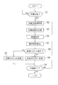
- step S1 of FIG. 3 it is determined whether or not the worker has started work. For example, when the worker operates a start button (not shown), it is determined that the work has started. If it is determined that the work has started, the process proceeds to step S2. On the other hand, if it is determined that the work has not started, step S1 is repeated. That is, the control device 1 stands by until work is started.
- step S2 the worker information acquisition unit 21 (see FIG. 2) acquires position information and posture information for each part of the worker. Specifically, based on acceleration data and angular velocity data input from each detection device 2, position information and posture information of each part are calculated.
- step S3 the motion calculation unit 24 (see FIG. 2) calculates the motion information of each part of the worker. Specifically, the position information and posture information of each part are input to the human body model recorded in the human body model recording unit 23, whereby the operation information of each part of the operator is calculated.
- step S4 the myoelectric acquisition unit 25 (see FIG. 2) acquires myoelectric signals for the various muscles of the worker. This myoelectric signal is detected by the detection device 3, and the detection result is input to the myoelectric acquisition unit 25.
- step S5 the motion intention estimation unit 26 (see FIG. 2) estimates the motion intention of each part of the worker based on the myoelectric signal acquired by the myoelectric acquisition unit 25.
- step S6 the operation determination unit 27 determines whether or not the operator's operation is an operation contrary to the operation intention. Specifically, based on the motion information calculated by the motion calculation unit 24 and the motion intention estimated by the motion intention estimation unit 26, it is determined whether or not the worker's motion is a motion contrary to the motion intention. Determined. If it is determined that the worker's motion is not a motion contrary to the motion intention, that is, if the worker's motion is the motion as intended, the process proceeds to step S7. On the other hand, when it is determined that the operation of the worker is an operation contrary to the operation intention, the process proceeds to step S8.
- step S7 normal robot control is performed by the robot controller 28 (see FIG. 2). For example, by operating the robot 50 based on the control program, the robot 50 performs a predetermined normal operation.
- step S8 the robot control unit 28 performs predetermined robot control. For example, when the worker is physically moving even though there is no intention of movement, the worker may be moved by the robot 50 or may collide with something and approach the robot 50. Stop operation. In addition, if the worker is not physically moving even though there is an intention to operate, the worker may have made a mistake, and thus the robot 50 is complemented by the worker's work.
- step S9 it is determined whether or not the worker has finished the work. For example, when the operator operates an end button (not shown), it is determined that the work is finished. If it is determined that the work has been completed, the process proceeds to the end. On the other hand, if it is determined that the work has not been completed, the process returns to step S2.
- the motion calculation unit 24 that acquires the motion information of the worker
- the motion intention estimation unit 26 that estimates the motion intention of the worker based on the myoelectric signal
- the motion information and the motion intention And an operation determination unit 27 that determines whether or not the operator's operation is an unintentional operation.
- the robot control unit 28 that controls the robot 50 is provided so that the robot 50 performs a predetermined operation when the operator's operation is an unintended operation. For example, when the worker is physically moving even though there is no movement intention, there is a possibility that the worker is moved in contact with the robot 50 or is approaching the robot 50 by colliding with something. By stopping the robot 50, safety can be improved. In addition, if the worker is not physically moving even though there is an intention to operate, the worker may have made a mistake. Therefore, by making the robot 50 complement the worker's work, productivity can be improved. Can be improved. As a result, it is possible to improve safety and productivity in a situation where the robot 50 and the worker work in cooperation.
- the motion calculation unit 24 calculates the motion information using the position information and posture information. it can.
- the motion calculation unit 24 improves the accuracy of the motion information by calculating the worker's motion information based on the worker's position information and posture information and the worker's human body model. Can be made.
- the human body model of the worker can be easily obtained by providing the human body model calculation unit 22 that calculates the human body model from the position information and the posture information.
- the robot 50 is a robot arm
- the present invention is not limited to this, and the control target may be a transport device that transports components. That is, the control object is, for example, an industrial machine.
- the present invention is not limited to this, and only the motion of the worker's local area (for example, the upper body) is detected. May be.
- the present invention is not limited to this, and only the motion intention of the worker's local area (for example, the upper body) is detected. You may do it.
- worn with an operator was shown, not only this but the detection apparatus with which an operator is mounted
- the worker information acquisition part 21, the human body model calculating part 22, the action calculating part 24, the myoelectric acquisition part 25, the action intention estimation part 26, and the action determination part 27 and the robot control unit 28 are shown as examples.
- the present invention is not limited to this, and the worker information acquisition unit, the human body model calculation unit, the movement calculation unit, the myoelectric acquisition unit, the movement intention estimation unit, the movement determination unit, and Each robot control unit may be configured by hardware.
- the present embodiment the example in which the position information and the posture information are calculated based on the acceleration data and the angular velocity data is shown.
- the present invention is not limited to this, and based on the velocity data, the angular acceleration data, the pressure data, the magnetic data, and the like.
- the position information and the posture information may be calculated. That is, although the example in which the detection device 2 detects acceleration data and angular velocity data has been shown, the detection device is not limited to this, and the detection device may include acceleration data, angular velocity data, velocity data, angular acceleration data, pressure data, and magnetic data. What is necessary is just to be comprised so that at least 1 may be detected.
- the motion intention is estimated based on the myoelectric signal.
- the present invention is not limited to this, and the motion intention is estimated based on other biological signals such as an electroencephalogram signal and a cerebral blood flow signal. You may do it. That is, although the example in which the detection device 3 detects the myoelectric signal has been shown, the present invention is not limited thereto, and the detection device is configured to detect at least one of the electroencephalogram signal, the cerebral blood flow signal, and the myoelectric signal. It only has to be done. That is, the motion intention may be estimated based on one type of biological signal, or the motion intention may be estimated based on a plurality of types of biological signals.
- the worker information acquisition unit 21 acquires the acceleration data and the angular velocity data, and calculates the position information and the posture information using the acceleration data and the angular velocity data.
- the worker information acquisition unit acquires at least one of acceleration data, angular velocity data, velocity data, angular acceleration data, pressure data, and magnetic data, and uses the acquired data for position information and posture information. At least one of them may be calculated.
- the human body model calculating part 22 showed the example which calculates a human body model of an operator based on position information and attitude
- the human body model of the operator may be calculated based on the above.
- the human body model calculating part 22 was provided in the control apparatus 1 and the human body model was input from the tool apparatus 60, the human body model calculating part 22 was not limited to this. The human body model may not be input from the tool device 60.
- the human body model recording unit 23 is provided, but the present invention is not limited thereto, and the human body model recording unit may not be provided.
- the motion calculation part 24 showed the example which calculates motion information from position information and attitude
- the motion information may be calculated from the human body model, or the motion information may be calculated based on at least one of the position information and the posture information regardless of the human body model.
- the myoelectric acquisition unit 25 to which the myoelectric signal is input is provided, but the present invention is not limited thereto, and the work is performed based on other biological signals such as an electroencephalogram signal and a cerebral blood flow signal.
- a biological signal acquisition unit to which the biological signal is input may be provided.
- the motion intention estimation unit 26 estimates the motion intention based on the myoelectric signal.
- the motion intention estimation unit includes an electroencephalogram signal, a cerebral blood flow signal, and the like.
- the operator's motion intention may be estimated based on other biological signals.
- the robot 50 is stopped when the worker's motion is against the motion intention and the worker is physically moving without the motion intention.
- the present invention is not limited to this, and when the operator's motion is against the motion intention and the worker is physically moving even though there is no motion intention, the robot may be operated to avoid or decelerate. Good.
- the avoidance operation is an operation for avoiding contact with the worker by retracting the robot from the current position.
- the deceleration operation is an operation that decreases the operation speed of the robot.
- an example is shown in which it is determined that the work has started when the start button is operated.
- the present invention is not limited thereto, and the work starts when the worker enters a predetermined work area. You may make it judge that it was carried out.
- an example is shown in which it is determined that the work is finished when the end button is operated.
- the present invention is not limited thereto, and it is determined that the work is finished when the worker leaves the predetermined work area. You may do it.
- the motion intention of the worker is estimated after the motion information of the worker is calculated.
- the present invention is not limited to this, and the calculation of motion information and the estimation of motion intention are performed simultaneously.
- the motion information may be calculated after estimating the motion intention. That is, the flowchart of this embodiment is an example and is not limited to the procedure.
- a robot information acquisition unit (not shown) that acquires various information (for example, position information, speed information, and route information) of the robot 50 is provided, and the robot 50 is controlled in consideration of the various information. You may make it do.
- the control device 1 is provided with an operator information acquisition unit 21 that acquires the position information and posture information of the worker, and an operation calculation unit 24 that calculates operation information from the position information and posture information.
- an operation acquisition unit that acquires the operation information of the worker is provided in the control device. In other words, as long as the control device can acquire the operation information from the outside, the function unit for calculating the operation information may not be provided in the control device.
- the present invention can be used for a determination device, a control device, a control system, a determination method, and a program.
- Control device (computer) 2 Detection device (first detection device) 3 Detection device (second detection device) 12a program 21 worker information acquisition unit (status acquisition unit) 22 human body model calculation unit 23 human body model recording unit 24 motion calculation unit (motion acquisition unit) 26 motion intention estimation unit 27 motion determination unit 28 robot control unit (control unit) 40 determination unit (determination device) 50 Robot (control target) 100 Control system
Abstract
判定装置(40)は、作業者の動作情報を取得する動作取得部(24)と、作業者の生体信号に基づいて作業者の動作意図を推定する動作意図推定部(26)と、動作情報と動作意図とに基づいて、作業者の動作が意図に反した動作であるか否かを判定する動作判定部(27)とを備える。
Description
本発明は、判定装置、制御装置、制御システム、判定方法およびプログラムに関する。
従来、工場の生産ラインなどに設置される産業用ロボットが知られている。また、近年では、生産ラインにおいて作業者を産業用ロボットが補助する作業補助システムが提案されている(たとえば、特許文献1参照)。
特許文献1の作業補助システムは、作業者が部品取付作業を行う際に、産業用ロボットに補助させるものであり、部品の一端側を作業者が保持するとともに、部品の他端側を産業用ロボットに保持させ、その部品を取付位置まで移動させるようになっている。具体的には、作業補助システムは、作業者の手に装着されるモーションキャプチャと、そのモーションキャプチャの検出結果に基づいて産業用ロボットを制御するデータ処理装置とを備えている。
モーションキャプチャは、作業者の手による作業動作を経時的に測定し、その測定結果である動作情報を3次元座標データとしてデータ処理装置に送信するように構成されている。データ処理装置は、モーションキャプチャからの3次元座標データに基づいて、産業用ロボットを作業者の手に追従させるように構成されている。これにより、部品の搬送を産業用ロボットに補助させることができるので、部品取付作業を効率的に行うことが可能である。
ここで、工場の生産ラインなどにおいて、産業用ロボットおよび作業者が協調して作業を行う状況下では、作業を行う作業者の動作が意図に反した動作であるか否かを判定することが望まれる。たとえば、作業者の動作が意図に反した動作であると判定することができれば、産業用ロボットに所定の動作をさせることにより、安全性および生産性を向上させることが可能である。
なお、特許文献2には、装着者に対してアシスト力を付与する駆動源と、装着者の動作に応じた関節角度(物理現象)を検出する物理現象検出手段と、装着者が発生する筋力に応じた筋電位(生体信号)を検出する生体信号検出手段とを備える装着式の動作補助装置が記載されている。この動作補助装置では、装着者が動作途中でその動作を中止し、別の動作を行う場合にも、装着者の意図が反映されるように駆動源を制御するようになっている。すなわち、特許文献2の動作補助装置は、装着者の意図したとおりにアシスト力を発生させるためのものであり、作業者の動作が意図に反した動作であるか否かを判定するものではない。
本発明は、上記の課題を解決するためになされたものであり、本発明の目的は、作業者の動作が意図に反した動作であるか否かを判定することが可能な判定装置、制御装置、制御システム、判定方法およびプログラムを提供することである。
本発明による判定装置は、作業者の動作情報を取得する動作取得部と、作業者の生体信号に基づいて作業者の動作意図を推定する動作意図推定部と、動作情報と動作意図とに基づいて、作業者の動作が意図に反した動作であるか否かを判定する動作判定部とを備える。なお、作業者の動作が意図に反した動作であるとは、たとえば、動作意図に反して作業者が動作している場合(作業者が意図することなく強制的に動かされている場合)と、動作意図に反して作業者が動作していない場合(作業者が意図したとおりに動けていない場合)とを含む。
このように構成することによって、動作情報と動作意図とに基づいて、作業者の動作が意図に反した動作であるか否かを適切に判定することができる。
上記判定装置において、生体信号は、脳波信号、脳血流信号および筋電信号のうちの少なくとも1つを含んでいてもよい。
上記判定装置において、作業者の位置情報および姿勢情報の少なくともいずれか一方を取得する状態取得部を備え、動作取得部は、位置情報および姿勢情報の少なくともいずれか一方に基づいて、動作情報を演算するように構成されていてもよい。
上記状態取得部を備える判定装置において、状態取得部は、加速度データ、角速度データ、速度データ、角加速度データ、圧力データおよび磁気データのうちの少なくとも1つを取得し、その取得したデータを用いて位置情報および姿勢情報の少なくともいずれか一方を算出するように構成されていてもよい。
上記状態取得部を備える判定装置において、動作取得部は、位置情報および姿勢情報の少なくともいずれか一方と、作業者の人体モデルとに基づいて、動作情報を演算するように構成されていてもよい。
上記人体モデルを用いて動作情報を演算する判定装置において、人体モデルが記録された人体モデル記録部を備えていてもよい。
上記人体モデルを用いて動作情報を演算する判定装置において、位置情報および姿勢情報の少なくともいずれか一方から人体モデルを演算する人体モデル演算部を備えていてもよい。
本発明による制御装置は、上記判定装置と、制御対象を制御する制御部とを備え、制御部は、判定装置の判定結果に基づいて制御対象を動作させるように構成されている。
上記制御装置において、制御部は、判定装置の動作判定部により作業者の動作が意図に反した動作であると判定された場合に、制御対象を回避動作、停止動作または減速動作させるように構成されていてもよい。
上記制御装置において、制御部は、判定装置の動作判定部により作業者の動作が意図に反した動作であると判定された場合に、作業者の作業を制御対象に補完させるように構成されていてもよい。
本発明による制御システムは、上記制御装置と、作業者に装着される第1検出装置および第2検出装置とを備える。
上記制御システムにおいて、第1検出装置は、加速度データ、角速度データ、速度データ、角加速度データ、圧力データおよび磁気データのうちの少なくとも1つを検出するように構成され、判定装置は、第1検出装置の検出結果に基づいて、作業者の位置情報および姿勢情報の少なくともいずれか一方を取得する状態取得部を含み、判定装置の動作取得部は、位置情報および姿勢情報の少なくともいずれか一方に基づいて、動作情報を演算するように構成されていてもよい。
上記制御システムにおいて、生体信号は、脳波信号、脳血流信号および筋電信号のうちの少なくとも1つを含み、第2検出装置は、脳波信号、脳血流信号および筋電信号のうちの少なくとも1つを検出するように構成され、判定装置の動作意図推定部は、第2検出装置の検出結果に基づいて動作意図を推定するように構成されていてもよい。
本発明による判定方法は、作業者の動作情報を取得するステップと、作業者の生体信号に基づいて作業者の動作意図を推定するステップと、動作情報と動作意図とに基づいて、作業者の動作が意図に反した動作であるか否かを判定するステップとを備える。
本発明によるプログラムは、上記した判定方法をコンピュータに実行させるためのものである。
本発明の判定装置、制御装置、制御システム、判定方法およびプログラムによれば、作業者の動作が意図に反した動作であるか否かを判定することができる。
以下、本発明の一実施形態について図面を参照して説明する。
まず、図1および図2を参照して、本発明の一実施形態による制御システム100の構成について説明する。
制御システム100は、図1に示すように、ロボット50を制御する制御装置1と、作業者に装着される検出装置2および3とを備えている。この制御システム100は、たとえば工場の生産ラインなどにおいて、作業者の動作が意図に反した動作であるか否かを判定するとともに、作業者の動作が意図に反した動作である場合にロボット50に所定の動作をさせるように構成されている。なお、ロボット50は、たとえば工場の生産ラインなどに設置されるロボットアームであり、本発明の「制御対象」の一例である。
検出装置2は、作業者の各部位に取り付けられており、各検出装置2は、取り付けられた部位についての動作を検出するために設けられている。なお、図1では2つの検出装置2を示したが、作業者の全身の動作を検出するためにより多数の検出装置2が設けられていてもよい。作業者に対する検出装置2の取付位置の一例としては、頭部、両肩部、両腕部(上腕、前腕、手)、背中部、腰部、および、両脚部(腿、脛、足)である。
各検出装置2は、加速度データを検出する加速度センサ2aと、角速度データを検出する角速度センサ2bと、加速度センサ2aおよび角速度センサ2bの検出結果を制御装置1に出力する出力部2cとを含んでいる。なお、検出装置2は、たとえば無線で制御装置1に接続されているが、有線で制御装置1に接続されていてもよい。また、検出装置2は、本発明の「第1検出装置」の一例である。
検出装置3は、作業者が動作する際に動かす各種筋肉に対応するように取り付けられている。複数の検出装置3は、作業者の各部位についての動作意図を検出するために設けられている。なお、図1では2つの検出装置3を示したが、作業者の全身の動作意図を検出するためにより多数の検出装置3が設けられていてもよい。
各検出装置3は、作業者の動作に伴う筋電信号を検出する筋電センサ3aと、筋電センサ3aの検出結果を制御装置1に出力する出力部3bとを含んでいる。なお、検出装置3は、たとえば無線で制御装置1に接続されているが、有線で制御装置1に接続されていてもよい。また、検出装置3は、本発明の「第2検出装置」の一例であり、筋電信号は、本発明の「生体信号」の一例である。
制御装置1は、検出装置2および3の検出結果に基づいて作業者の動作が意図に反した動作であるか否かを判定し、意図に反した動作である場合にロボット50に所定の動作をさせるように構成されている。作業者の動作が意図に反した動作であるとは、たとえば、動作意図に反して作業者が動作している場合(作業者が意図することなく強制的に動かされている場合)と、動作意図に反して作業者が動作していない場合(作業者が意図したとおりに動けていない場合)とを含む。
制御装置1は、CPU11と、ROM12と、RAM13と、入出力部14とを含んでいる。CPU11は、ROM12に記憶されたプログラム12aなどに基づいて演算処理を実行するように構成されている。ROM12は、不揮発性のメモリであり、プログラム12aやそのプログラム12aの実行の際に用いられる設定値などを記憶している。なお、プログラム12aにはロボット50の制御プログラムなどが含まれている。RAM13は、揮発性のメモリであり、CPU11による演算結果や検出装置2および3の検出結果などを一時的に記憶する機能を有する。入出力部14には、複数の検出装置2、3、ロボット50、および、制御装置1の設定変更などを行うためのツール装置60などが接続されている。
また、制御装置1は、図2に示すように、作業者情報取得部21と、人体モデル演算部22と、人体モデル記録部23と、動作演算部24と、筋電取得部25と、動作意図推定部26と、動作判定部27と、ロボット制御部28とを含んでいる。なお、作業者情報取得部21、人体モデル演算部22、動作演算部24、筋電取得部25、動作意図推定部26、動作判定部27およびロボット制御部28は、CPU11がプログラム12aを実行することにより実現される。また、人体モデル記録部23は、ROM12の記憶領域の一部によって構成されている。
また、作業者情報取得部21、人体モデル演算部22、人体モデル記録部23、動作演算部24、筋電取得部25、動作意図推定部26および動作判定部27により、作業者の動作が意図に反した動作であるか否かを判定する判定部40が構成されている。なお、判定部40は、本発明の「判定装置」の一例である。
作業者情報取得部21は、各検出装置2の検出結果が入力されるように構成されている。すなわち、作業者情報取得部21は、作業者の各部位の加速度データおよび角速度データを経時的に取得している。そして、作業者情報取得部21は、その加速度データおよび角速度データを用いて位置情報および姿勢情報を算出するように構成されている。つまり、作業者情報取得部21は、作業者の部位毎についての位置情報および姿勢情報を経時的に取得している。なお、位置情報は、たとえば3次元座標の座標値であり、姿勢情報は、たとえば各座標軸に対する回転角である。また、作業者情報取得部21は、本発明の「状態取得部」の一例である。
人体モデル演算部22は、作業者情報取得部21により取得した位置情報および姿勢情報に基づいて、作業者の人体モデルを演算するために設けられている。ここで、作業者の人体モデルとは、たとえば、作業者の身体の各部位についての寸法をデータベース化したものである。この人体モデル演算部22は、作業者の各部位の位置情報および姿勢情報の経時変化から、各部位の寸法を算出することにより人体モデルを作成するようになっている。なお、人体モデル演算部22による人体モデルの演算時に、作業者に対して所定の動作を行うように促すようにしてもよい。
人体モデル記録部23には、作業者の人体モデルが記録されている。この人体モデル記録部23には、人体モデル演算部22の演算結果である人体モデルが記録されていてもよいし、ツール装置60を用いて作業者によって入力された人体モデルが記録されていてもよい。すなわち、本実施形態では、人体モデル記録部23に対する人体モデルの記録方法が2つあり、いずれの方法で記録されていてもよい。
動作演算部24は、人体モデル記録部23に記録された人体モデルに対して各部位の位置情報および姿勢情報を入力することにより作業者の各部位の動作情報を演算するように構成されている。すなわち、作業者の各部位の位置および姿勢の経時変化から、各部位の実際の物理的な動作を演算するようになっている。このため、動作演算部24は、動作情報を取得する機能を有する。なお、動作演算部24は、本発明の「動作取得部」の一例である。
筋電取得部25は、各検出装置3の検出結果が入力されるように構成されている。すなわち、筋電取得部25は、作業者の各種筋肉についての筋電信号を経時的に取得している。
動作意図推定部26は、筋電取得部25により取得した筋電信号に基づいて、作業者の動作意図を推定するために設けられている。この動作意図推定部26は、作業者の各種筋肉の筋電信号の変化から、作業者の各部位の動作意図を推定するようになっている。
動作判定部27は、作業者の動作が意図に反した動作であるか否かを判定するために設けられている。この動作判定部27は、動作演算部24により演算された動作情報と、動作意図推定部26により推定された動作意図とに基づいて、作業者の動作が意図に反した動作であるか否かを判定するように構成されている。
具体例として、動作判定部27は、動作情報と動作意図とが揃う場合に、作業者が意図したとおりに動作していることから、意図に反する動作ではないと判定するように構成されている。なお、動作情報と動作意図とが揃うとは、たとえば、動作意図に対して動作情報が所定範囲内である場合である。そして、動作判定部27は、動作情報と動作意図とが揃わない場合に、作業者の動作が意図に反した動作であると判定するようになっている。ここで、意図に反した動作には、動作意図がないのに作業者が物理的に動いている場合と、動作意図があるのに作業者が物理的に動いていない場合とが含まれており、動作判定部27はそれらを判定可能に構成されている。
ロボット制御部28は、ロボット50に対して動作指示を出力するために設けられている。たとえば、ロボット制御部28は、動作判定部27により作業者の動作が意図に反した動作ではないと判定された場合に、制御プログラムに基づいてロボット50を動作させることにより、予め決められた通常の作業をロボット50にさせるように構成されている。また、ロボット制御部28は、動作判定部27により作業者の動作が意図に反した動作であると判定された場合に、ロボット50に所定の動作をさせるように構成されている。なお、ロボット制御部28は、本発明の「制御部」の一例である。
ここで、本実施形態の所定の動作には、ロボット50を停止させる停止動作と、ロボット50に作業者の作業を補完させる動作とが含まれている。たとえば、動作意図がないのに作業者が物理的に動いている場合には、作業者がロボット50により動かされたり、何かと衝突してロボット50に接近している可能性があるため、ロボット50を停止動作させる。また、動作意図があるのに作業者が物理的に動いていない場合には、作業者がミスをしている可能性があるため、作業者の作業をロボット50に補完させるようになっている。
-制御システムの動作-
次に、図3を参照して、本実施形態の制御システム100の動作について説明する。
次に、図3を参照して、本実施形態の制御システム100の動作について説明する。
なお、以下の各ステップはCPU11(図1参照)がプログラム12a(図1参照)を実行することにより行われる。すなわち、プログラム12aは、以下の各ステップを制御装置1(図1参照)に実行させるためのものであり、制御装置1が読み取り可能な記録媒体であるROM12(図1参照)に格納されている。
また、人体モデル記録部23(図2参照)には作業者の人体モデルが予め記録されている。この人体モデルは、人体モデル演算部22(図2参照)により記録されていてもよいし、ツール装置60(図2参照)を用いて記録されていてもよい。そして、作業者の各部位には検出装置2(図2参照)が装着され、作業者の各種筋肉に対応するように検出装置3(図2参照)が装着されている。
まず、図3のステップS1において、作業者が作業を開始したか否かが判断される。たとえば、作業者が開始ボタン(図示省略)を操作した場合に、作業が開始されたと判断される。そして、作業が開始されたと判断された場合には、ステップS2に移る。その一方、作業が開始されていないと判断された場合には、ステップS1が繰り返し行われる。すなわち、作業が開始されるまで制御装置1が待機する。
次に、ステップS2において、作業者情報取得部21(図2参照)により、作業者の部位毎についての位置情報および姿勢情報が取得される。具体的には、各検出装置2から入力される加速度データおよび角速度データに基づいて、各部位の位置情報および姿勢情報が算出される。
次に、ステップS3において、動作演算部24(図2参照)により、作業者の各部位の動作情報が演算される。具体的には、人体モデル記録部23に記録された人体モデルに対して各部位の位置情報および姿勢情報が入力されることにより、作業者の各部位の動作情報が演算される。
また、ステップS4において、筋電取得部25(図2参照)により、作業者の各種筋肉についての筋電信号が取得される。この筋電信号は検出装置3により検出され、その検出結果が筋電取得部25に入力される。
次に、ステップS5において、動作意図推定部26(図2参照)により、筋電取得部25が取得した筋電信号に基づいて、作業者の各部位の動作意図が推定される。
次に、ステップS6において、動作判定部27(図2参照)により、作業者の動作が動作意図に反した動作であるか否かが判定される。具体的には、動作演算部24により演算された動作情報と、動作意図推定部26により推定された動作意図とに基づいて、作業者の動作が動作意図に反した動作であるか否かが判定される。そして、作業者の動作が動作意図に反した動作ではないと判定された場合、すなわち、作業者の動作が意図したとおりの動作である場合には、ステップS7に移る。その一方、作業者の動作が動作意図に反した動作であると判定された場合には、ステップS8に移る。
そして、ステップS7では、ロボット制御部28(図2参照)により、通常のロボット制御が行われる。たとえば、制御プログラムに基づいてロボット50を動作させることにより、ロボット50が予め決められた通常の作業を行う。
また、ステップS8では、ロボット制御部28により、所定のロボット制御が行われる。たとえば、動作意図がないのに作業者が物理的に動いている場合には、作業者がロボット50により動かされたり、何かと衝突してロボット50に接近している可能性があるため、ロボット50を停止動作させる。また、動作意図があるのに作業者が物理的に動いていない場合には、作業者がミスをしている可能性があるため、作業者の作業をロボット50に補完させる。
その後、ステップS9において、作業者が作業を終了したか否かが判断される。たとえば、作業者が終了ボタン(図示省略)を操作した場合に、作業が終了されたと判断される。そして、作業が終了されたと判断された場合には、エンドに移る。その一方、作業が終了されていないと判断された場合には、ステップS2に戻る。
-効果-
本実施形態では、上記のように、作業者の動作情報を取得する動作演算部24と、筋電信号に基づいて作業者の動作意図を推定する動作意図推定部26と、動作情報および動作意図に基づいて作業者の動作が意図に反した動作であるか否かを判定する動作判定部27とが設けられている。このように構成することによって、動作情報と動作意図とに基づいて、作業者の動作が意図に反した動作であるか否かを適切に判定することができる。
本実施形態では、上記のように、作業者の動作情報を取得する動作演算部24と、筋電信号に基づいて作業者の動作意図を推定する動作意図推定部26と、動作情報および動作意図に基づいて作業者の動作が意図に反した動作であるか否かを判定する動作判定部27とが設けられている。このように構成することによって、動作情報と動作意図とに基づいて、作業者の動作が意図に反した動作であるか否かを適切に判定することができる。
また、本実施形態では、ロボット50を制御するロボット制御部28が設けられ、作業者の動作が意図に反した動作である場合にロボット50に所定の動作をさせるようになっている。たとえば、動作意図がないのに作業者が物理的に動いている場合には、作業者がロボット50に接触して動かされたり、何かと衝突してロボット50に接近している可能性があるため、ロボット50を停止動作させることにより、安全性の向上を図ることができる。また、動作意図があるのに作業者が物理的に動いていない場合には、作業者がミスをしている可能性があるため、作業者の作業をロボット50に補完させることにより、生産性の向上を図ることができる。その結果、ロボット50および作業者が協調して作業を行う状況下において、安全性および生産性の向上を図ることができる。
また、本実施形態では、作業者の位置情報および姿勢情報を取得する作業者情報取得部21を設けることによって、その位置情報および姿勢情報を用いて動作演算部24が動作情報を演算することができる。
また、本実施形態では、動作演算部24が、作業者の位置情報および姿勢情報とその作業者の人体モデルとに基づいて、作業者の動作情報を演算することによって、動作情報の精度を向上させることができる。
また、本実施形態では、位置情報および姿勢情報から人体モデルを演算する人体モデル演算部22を設けることによって、作業者の人体モデルを容易に得ることができる。
-他の実施形態-
なお、今回開示した実施形態は、すべての点で例示であって、限定的な解釈の根拠となるものではない。したがって、本発明の技術的範囲は、上記した実施形態のみによって解釈されるものではなく、特許請求の範囲の記載に基づいて画定される。また、本発明の技術的範囲には、特許請求の範囲と均等の意味および範囲内でのすべての変更が含まれる。
なお、今回開示した実施形態は、すべての点で例示であって、限定的な解釈の根拠となるものではない。したがって、本発明の技術的範囲は、上記した実施形態のみによって解釈されるものではなく、特許請求の範囲の記載に基づいて画定される。また、本発明の技術的範囲には、特許請求の範囲と均等の意味および範囲内でのすべての変更が含まれる。
たとえば、本実施形態では、ロボット50がロボットアームである例を示したが、これに限らず、制御対象が部品を搬送する搬送装置などであってもよい。すなわち、制御対象はたとえば産業機械である。
また、本実施形態では、複数の検出装置2により作業者の全身の動作を検出する例を示したが、これに限らず、作業者の局部(たとえば、上半身)の動作のみを検出するようにしてもよい。
また、本実施形態では、複数の検出装置3により作業者の全身の動作意図を検出する例を示したが、これに限らず、作業者の局部(たとえば、上半身)の動作意図のみを検出するようにしてもよい。また、複数の検出装置3が作業者に装着される例を示したが、これに限らず、作業者に装着される検出装置が単数であってもよい。
また、本実施形態では、CPU11がプログラム12aを実行することにより、作業者情報取得部21、人体モデル演算部22、動作演算部24、筋電取得部25、動作意図推定部26、動作判定部27およびロボット制御部28が実現される例を示したが、これに限らず、作業者情報取得部、人体モデル演算部、動作演算部、筋電取得部、動作意図推定部、動作判定部およびロボット制御部がそれぞれハードウェアで構成されていてもよい。
また、本実施形態では、加速度データおよび角速度データに基づいて、位置情報および姿勢情報を算出する例を示したが、これに限らず、速度データ、角加速度データ、圧力データおよび磁気データなどに基づいて、位置情報および姿勢情報を算出するようにしてもよい。すなわち、検出装置2が加速度データおよび角速度データを検出する例を示したが、これに限らず、検出装置は、加速度データ、角速度データ、速度データ、角加速度データ、圧力データおよび磁気データのうちの少なくとも1つを検出するように構成されていればよい。
また、本実施形態では、筋電信号に基づいて動作意図を推定する例を示したが、これに限らず、脳波信号および脳血流信号などの他の生体信号に基づいて動作意図を推定するようにしてもよい。すなわち、検出装置3が筋電信号を検出する例を示したが、これに限らず、検出装置は、脳波信号、脳血流信号および筋電信号のうちの少なくとも1つを検出するように構成されていればよい。つまり、1種類の生体信号に基づいて動作意図を推定するようにしてもよいし、複数種類の生体信号に基づいて動作意図を推定するようにしてもよい。
また、本実施形態では、作業者情報取得部21が、加速度データおよび角速度データを取得し、その加速度データおよび角速度データを用いて位置情報および姿勢情報を算出する例を示したが、これに限らず、作業者情報取得部が、加速度データ、角速度データ、速度データ、角加速度データ、圧力データおよび磁気データのうちの少なくとも1つを取得し、その取得したデータを用いて位置情報および姿勢情報の少なくともいずれか一方を算出するようにすればよい。
また、本実施形態では、人体モデル演算部22が位置情報および姿勢情報に基づいて作業者の人体モデルを演算する例を示したが、これに限らず、人体モデル演算部が位置情報または姿勢情報に基づいて作業者の人体モデルを演算するようにしてもよい。
また、本実施形態では、制御装置1に人体モデル演算部22が設けられるとともに、ツール装置60から人体モデルを入力可能に構成する例を示したが、これに限らず、人体モデル演算部22が設けられていなくてもよいし、ツール装置60から人体モデルを入力できないようにしてもよい。
また、本実施形態では、人体モデル記録部23が設けられる例を示したが、これに限らず、人体モデル記録部が設けられていなくてもよい。
また、本実施形態では、動作演算部24が、位置情報および姿勢情報と人体モデルとから動作情報を演算する例を示したが、これに限らず、動作演算部が、位置情報または姿勢情報と人体モデルとから動作情報を演算するようにしてもよいし、人体モデルによらず、位置情報および姿勢情報の少なくともいずれか一方に基づいて動作情報を演算するようにしてもよい。
また、本実施形態では、筋電信号が入力される筋電取得部25が設けられる例を示したが、これに限らず、脳波信号および脳血流信号などの他の生体信号に基づいて作業者の動作意図を推定する場合には、その生体信号が入力される生体信号取得部が設けられていればよい。
また、本実施形態では、動作意図推定部26が、筋電信号に基づいて動作意図を推定する例を示したが、これに限らず、動作意図推定部が、脳波信号および脳血流信号などの他の生体信号に基づいて作業者の動作意図を推定するようにしてもよい。
また、本実施形態では、作業者の動作が動作意図に反した動作であり、動作意図がないのに作業者が物理的に動いている場合に、ロボット50を停止動作させる例を示したが、これに限らず、作業者の動作が動作意図に反した動作であり、動作意図がないのに作業者が物理的に動いている場合に、ロボットを回避動作または減速動作させるようにしてもよい。なお、回避動作とは、ロボットを現在の位置から退避させることにより、作業者との接触を回避させる動作である。また、減速動作とは、ロボットの動作速度を減少させる動作である。
また、本実施形態では、開始ボタンが操作された場合に、作業が開始されたと判断する例を示したが、これに限らず、作業者が所定の作業領域に進入した場合に、作業が開始されたと判断するようにしてもよい。同様に、終了ボタンが操作された場合に、作業が終了されたと判断する例を示したが、これに限らず、作業者が所定の作業領域から退出した場合に、作業が終了されたと判断するようにしてもよい。
また、本実施形態では、作業者の動作情報を演算した後に、作業者の動作意図を推定する例を示したが、これに限らず、動作情報の演算と動作意図の推定とを同時に行うようにしてもよいし、動作意図を推定した後に動作情報を演算するようにしてもよい。すなわち、本実施形態のフローチャートは、一例であってその手順に限定されるものではない。
また、本実施形態において、ロボット50の各種情報(たとえば、位置情報、速度情報および経路情報)を取得するロボット情報取得部(図示省略)が設けられ、その各種情報を考慮してロボット50を制御するようにしてもよい。
また、本実施形態では、作業者の位置情報および姿勢情報を取得する作業者情報取得部21と、その位置情報および姿勢情報から動作情報を演算する動作演算部24とが制御装置1に設けられる例を示したが、これに限らず、作業者の動作情報を取得する動作取得部が制御装置に設けられていればよい。すなわち、制御装置が動作情報を外部から取得可能であれば、動作情報を算出する機能部が制御装置に設けられていなくてもよい。
本発明は、判定装置、制御装置、制御システム、判定方法およびプログラムに利用可能である。
1 制御装置(コンピュータ)
2 検出装置(第1検出装置)
3 検出装置(第2検出装置)
12a プログラム
21 作業者情報取得部(状態取得部)
22 人体モデル演算部
23 人体モデル記録部
24 動作演算部(動作取得部)
26 動作意図推定部
27 動作判定部
28 ロボット制御部(制御部)
40 判定部(判定装置)
50 ロボット(制御対象)
100 制御システム
2 検出装置(第1検出装置)
3 検出装置(第2検出装置)
12a プログラム
21 作業者情報取得部(状態取得部)
22 人体モデル演算部
23 人体モデル記録部
24 動作演算部(動作取得部)
26 動作意図推定部
27 動作判定部
28 ロボット制御部(制御部)
40 判定部(判定装置)
50 ロボット(制御対象)
100 制御システム
Claims (15)
- 作業者の動作情報を取得する動作取得部と、
作業者の生体信号に基づいて作業者の動作意図を推定する動作意図推定部と、
前記動作情報と前記動作意図とに基づいて、作業者の動作が意図に反した動作であるか否かを判定する動作判定部とを備えることを特徴とする判定装置。 - 請求項1に記載の判定装置において、
前記生体信号は、脳波信号、脳血流信号および筋電信号のうちの少なくとも1つを含むことを特徴とする判定装置。 - 請求項1または2に記載の判定装置において、
作業者の位置情報および姿勢情報の少なくともいずれか一方を取得する状態取得部を備え、
前記動作取得部は、前記位置情報および前記姿勢情報の少なくともいずれか一方に基づいて、前記動作情報を演算するように構成されていることを特徴とする判定装置。 - 請求項3に記載の判定装置において、
前記状態取得部は、加速度データ、角速度データ、速度データ、角加速度データ、圧力データおよび磁気データのうちの少なくとも1つを取得し、その取得したデータを用いて前記位置情報および前記姿勢情報の少なくともいずれか一方を算出するように構成されていることを特徴とする判定装置。 - 請求項3または4に記載の判定装置において、
前記動作取得部は、前記位置情報および前記姿勢情報の少なくともいずれか一方と、作業者の人体モデルとに基づいて、前記動作情報を演算するように構成されていることを特徴とする判定装置。 - 請求項5に記載の判定装置において、
前記人体モデルが記録された人体モデル記録部を備えることを特徴とする判定装置。 - 請求項5または6に記載の判定装置において、
前記位置情報および前記姿勢情報の少なくともいずれか一方から前記人体モデルを演算する人体モデル演算部を備えることを特徴とする判定装置。 - 請求項1~7のいずれか1つに記載の判定装置と、
制御対象を制御する制御部とを備え、
前記制御部は、前記判定装置の判定結果に基づいて前記制御対象を動作させるように構成されていることを特徴とする制御装置。 - 請求項8に記載の制御装置において、
前記制御部は、前記判定装置の動作判定部により作業者の動作が意図に反した動作であると判定された場合に、前記制御対象を回避動作、停止動作または減速動作させるように構成されていることを特徴とする制御装置。 - 請求項8または9に記載の制御装置において、
前記制御部は、前記判定装置の動作判定部により作業者の動作が意図に反した動作であると判定された場合に、作業者の作業を前記制御対象に補完させるように構成されていることを特徴とする制御装置。 - 請求項8~10のいずれか1つに記載の制御装置と、
作業者に装着される第1検出装置および第2検出装置とを備えることを特徴とする制御システム。 - 請求項11に記載の制御システムにおいて、
前記第1検出装置は、加速度データ、角速度データ、速度データ、角加速度データ、圧力データおよび磁気データのうちの少なくとも1つを検出するように構成され、
前記判定装置は、前記第1検出装置の検出結果に基づいて、作業者の位置情報および姿勢情報の少なくともいずれか一方を取得する状態取得部を含み、
前記判定装置の動作取得部は、前記位置情報および前記姿勢情報の少なくともいずれか一方に基づいて、前記動作情報を演算するように構成されていることを特徴とする制御システム。 - 請求項11または12に記載の制御システムにおいて、
前記生体信号は、脳波信号、脳血流信号および筋電信号のうちの少なくとも1つを含み、
前記第2検出装置は、前記脳波信号、前記脳血流信号および前記筋電信号のうちの少なくとも1つを検出するように構成され、
前記判定装置の動作意図推定部は、前記第2検出装置の検出結果に基づいて前記動作意図を推定するように構成されていることを特徴とする制御システム。 - 作業者の動作情報を取得するステップと、
作業者の生体信号に基づいて作業者の動作意図を推定するステップと、
前記動作情報と前記動作意図とに基づいて、作業者の動作が意図に反した動作であるか否かを判定するステップとを備えることを特徴とする判定方法。 - 請求項14に記載の判定方法をコンピュータに実行させるためのプログラム。
Applications Claiming Priority (2)
| Application Number | Priority Date | Filing Date | Title |
|---|---|---|---|
| JP2016025966A JP2017143896A (ja) | 2016-02-15 | 2016-02-15 | 判定装置、制御装置、制御システム、判定方法およびプログラム |
| JP2016-025966 | 2016-11-30 |
Publications (1)
| Publication Number | Publication Date |
|---|---|
| WO2017141579A1 true WO2017141579A1 (ja) | 2017-08-24 |
Family
ID=59625656
Family Applications (1)
| Application Number | Title | Priority Date | Filing Date |
|---|---|---|---|
| PCT/JP2017/000587 WO2017141579A1 (ja) | 2016-02-15 | 2017-01-11 | 判定装置、制御装置、制御システム、判定方法およびプログラム |
Country Status (2)
| Country | Link |
|---|---|
| JP (1) | JP2017143896A (ja) |
| WO (1) | WO2017141579A1 (ja) |
Families Citing this family (2)
| Publication number | Priority date | Publication date | Assignee | Title |
|---|---|---|---|---|
| JP6775481B2 (ja) * | 2017-11-07 | 2020-10-28 | 株式会社日立ビルシステム | 着脱作業管理装置、着脱作業管理システム |
| KR102111970B1 (ko) * | 2018-04-17 | 2020-05-18 | 연세대학교 원주산학협력단 | 장애 심사 평가를 위한 거짓말 탐지 기기 및 이것의 제어 방법 |
Citations (6)
| Publication number | Priority date | Publication date | Assignee | Title |
|---|---|---|---|---|
| JP2005230099A (ja) * | 2004-02-17 | 2005-09-02 | Yoshiyuki Yamaumi | 装着式動作補助装置、及び装着式動作補助装置における駆動源の制御方法、及びプログラム |
| JP2006075456A (ja) * | 2004-09-13 | 2006-03-23 | Tohoku Univ | 人体モデルに基づく装着型支援システム |
| JP2009066395A (ja) * | 2007-08-20 | 2009-04-02 | Univ Of Tsukuba | 装着式動作補助装置の動作補助システム及び装着式動作補助装置及び装着式動作補助装置の動作補助方法 |
| JP2010269418A (ja) * | 2009-05-22 | 2010-12-02 | Ihi Corp | ロボット制御装置およびその制御方法 |
| JP2012101284A (ja) * | 2010-11-05 | 2012-05-31 | Nagoya Univ | 人の動作における意図推定装置 |
| JP2013066669A (ja) * | 2011-09-26 | 2013-04-18 | Sony Corp | 運動補助装置及び運動補助方法、コンピューター・プログラム、並びにプログラム記録媒体 |
-
2016
- 2016-02-15 JP JP2016025966A patent/JP2017143896A/ja active Pending
-
2017
- 2017-01-11 WO PCT/JP2017/000587 patent/WO2017141579A1/ja active Application Filing
Patent Citations (6)
| Publication number | Priority date | Publication date | Assignee | Title |
|---|---|---|---|---|
| JP2005230099A (ja) * | 2004-02-17 | 2005-09-02 | Yoshiyuki Yamaumi | 装着式動作補助装置、及び装着式動作補助装置における駆動源の制御方法、及びプログラム |
| JP2006075456A (ja) * | 2004-09-13 | 2006-03-23 | Tohoku Univ | 人体モデルに基づく装着型支援システム |
| JP2009066395A (ja) * | 2007-08-20 | 2009-04-02 | Univ Of Tsukuba | 装着式動作補助装置の動作補助システム及び装着式動作補助装置及び装着式動作補助装置の動作補助方法 |
| JP2010269418A (ja) * | 2009-05-22 | 2010-12-02 | Ihi Corp | ロボット制御装置およびその制御方法 |
| JP2012101284A (ja) * | 2010-11-05 | 2012-05-31 | Nagoya Univ | 人の動作における意図推定装置 |
| JP2013066669A (ja) * | 2011-09-26 | 2013-04-18 | Sony Corp | 運動補助装置及び運動補助方法、コンピューター・プログラム、並びにプログラム記録媒体 |
Also Published As
| Publication number | Publication date |
|---|---|
| JP2017143896A (ja) | 2017-08-24 |
Similar Documents
| Publication | Publication Date | Title |
|---|---|---|
| CN109620410B (zh) | 机械臂防碰撞的方法及系统、医疗机器人 | |
| JP6678832B2 (ja) | 遠隔制御マニピュレータシステムおよび制御装置 | |
| JP5370127B2 (ja) | ロボットの干渉回避装置 | |
| JP6174654B2 (ja) | センサの位置と向きを算出する機能を備えたロボットシステム | |
| TW201707884A (zh) | 遠端操作機器人系統 | |
| US20150367510A1 (en) | Multi-joint robot having function for repositioning arm | |
| US11230004B2 (en) | Robot system and robot control method | |
| JP2010524548A5 (ja) | ||
| JP2007011978A (ja) | ロボットの運動制御装置 | |
| WO2017088888A1 (en) | Robot trajectory or path learning by demonstration | |
| CN109318244B (zh) | 多关节机器人的控制装置 | |
| US11602863B2 (en) | Device, method and program for estimating weight and position of gravity center of load by using robot | |
| US10591905B2 (en) | Work region estimation device, control device, control system, work region estimation method, and non-transitory computer-readable recording medium | |
| WO2017141579A1 (ja) | 判定装置、制御装置、制御システム、判定方法およびプログラム | |
| WO2017141569A1 (ja) | 制御装置、制御システム、制御方法およびプログラム | |
| KR101632034B1 (ko) | 수술 로봇 시스템 및 수술 로봇 시스템의 제어 방법 | |
| US10639799B2 (en) | Robot system | |
| JP2014087922A (ja) | ロボット制御装置及び方法 | |
| WO2017141570A1 (ja) | 監視装置、制御装置、制御システム、監視方法およびプログラム | |
| US10635080B2 (en) | Work region estimation device, control device, control system, work region estimation method, and non-transitory computer-readable recording medium | |
| Matsuzaka et al. | Assistance for master-slave system for objects of various shapes by eye gaze tracking and motion prediction | |
| JP6238110B2 (ja) | ロボットハンドの制御方法と制御装置 | |
| CN109834696B (zh) | 机器人示教系统、控制装置以及手动导向单元 | |
| JP6149791B2 (ja) | 重心推定装置、及び重心推定方法 | |
| KR101970951B1 (ko) | 로봇 매니퓰레이터 충돌 검출 장치 및 방법 |
Legal Events
| Date | Code | Title | Description |
|---|---|---|---|
| 121 | Ep: the epo has been informed by wipo that ep was designated in this application |
Ref document number: 17752843 Country of ref document: EP Kind code of ref document: A1 |
|
| NENP | Non-entry into the national phase |
Ref country code: DE |
|
| 122 | Ep: pct application non-entry in european phase |
Ref document number: 17752843 Country of ref document: EP Kind code of ref document: A1 |