WO2017138207A1 - 内視鏡プロセッサ、内視鏡システム - Google Patents
内視鏡プロセッサ、内視鏡システム Download PDFInfo
- Publication number
- WO2017138207A1 WO2017138207A1 PCT/JP2016/083767 JP2016083767W WO2017138207A1 WO 2017138207 A1 WO2017138207 A1 WO 2017138207A1 JP 2016083767 W JP2016083767 W JP 2016083767W WO 2017138207 A1 WO2017138207 A1 WO 2017138207A1
- Authority
- WO
- WIPO (PCT)
- Prior art keywords
- address
- spiral
- conversion table
- raster
- signal
- Prior art date
- Legal status (The legal status is an assumption and is not a legal conclusion. Google has not performed a legal analysis and makes no representation as to the accuracy of the status listed.)
- Ceased
Links
Images




Classifications
-
- A—HUMAN NECESSITIES
- A61—MEDICAL OR VETERINARY SCIENCE; HYGIENE
- A61B—DIAGNOSIS; SURGERY; IDENTIFICATION
- A61B1/00—Instruments for performing medical examinations of the interior of cavities or tubes of the body by visual or photographical inspection, e.g. endoscopes; Illuminating arrangements therefor
-
- A—HUMAN NECESSITIES
- A61—MEDICAL OR VETERINARY SCIENCE; HYGIENE
- A61B—DIAGNOSIS; SURGERY; IDENTIFICATION
- A61B1/00—Instruments for performing medical examinations of the interior of cavities or tubes of the body by visual or photographical inspection, e.g. endoscopes; Illuminating arrangements therefor
- A61B1/04—Instruments for performing medical examinations of the interior of cavities or tubes of the body by visual or photographical inspection, e.g. endoscopes; Illuminating arrangements therefor combined with photographic or television appliances
-
- G—PHYSICS
- G02—OPTICS
- G02B—OPTICAL ELEMENTS, SYSTEMS OR APPARATUS
- G02B23/00—Telescopes, e.g. binoculars; Periscopes; Instruments for viewing the inside of hollow bodies; Viewfinders; Optical aiming or sighting devices
- G02B23/24—Instruments or systems for viewing the inside of hollow bodies, e.g. fibrescopes
Definitions
- the present invention relates to an endoscope processor and an endoscope system that generate an image by receiving a return light of an irradiation light spot that scans a subject.
- An endoscope processor that generates an image by receiving a return light of an irradiation light spot that scans an object, and an endoscope system that includes the endoscope processor have been proposed as a scanning endoscope system. .
- the scanning endoscope system constructs an image by the following method, for example.
- the irradiation light spot is irradiated onto the subject, and scanning is performed with, for example, a spiral (spiral) scanning orbit.
- raster address (x, y) (0, 0), (0, 1), (0, 2),..., (P, q)).
- the scanning trajectory when the scanning endoscope is actually used is generally deviated from an ideal scanning trajectory determined from a design value or the like. Therefore, when mapping is performed in accordance with an ideal scanning trajectory, an accurate image cannot be obtained because the image is distorted.
- Japanese Patent No. 5190267 describes a calibration technique for correcting a detection signal obtained by scanning with a scanning trajectory deviating from the ideal. That is, in the technique described in the publication, first, the corrected conversion is performed by calibrating an ideal conversion table ⁇ n ⁇ (x, y) ⁇ from the spiral address n to the raster address (x, y). A table ⁇ n ⁇ (x ′, y ′) ⁇ is created. An accurate image is obtained by arranging (mapping) the detection signal at the raster address (x, y) using the corrected conversion table ⁇ n ⁇ (x ′, y ′) ⁇ . ing.
- the corrected conversion table is stored in, for example, a memory in an endoscope, and the endoscope processor reads from the memory of the connected endoscope.
- the data amount of the conversion table for mapping is proportional to the number of return light samples, that is, the maximum number m of spiral addresses n, but the number of return light samples necessary to fill the screen with a small irradiation light spot.
- m is a huge number.
- the amount of data in the conversion table for mapping becomes enormous and takes a long time to read, so the startup time from when the power is turned on until the image can be displayed becomes long.
- the present invention has been made in view of the above circumstances, and an object of the present invention is to provide an endoscope processor and an endoscope system capable of shortening the startup time while enabling accurate image display.
- An endoscope processor provides a first trajectory of a detection signal obtained by receiving return light of an irradiation light spot that scans a subject at a predetermined timing when the scanning is performed in a first trajectory.
- a processor memory configured to hold a first mapping table representing a correspondence relationship between an address and a first address of a two-dimensional coordinate representing a position on the subject; and second scanning of the detection signal.
- An input unit configured to input a second mapping table representing a correspondence relationship between a second trajectory address when performed on a trajectory and a second address of a two-dimensional coordinate representing the position on the subject; In the first period, the input of the second mapping table is started, and based on the first mapping table and the detection signal obtained in the first period, In the second period after generating the first pixel signal stored at the first address and completing the input of the second mapping table, the detection signal obtained in the second mapping table and the second period And a signal processing unit configured to generate a second pixel signal stored at the second address.
- An endoscope system includes the endoscope processor, an endoscope configured to scan the irradiation light spot and receive the return light from the subject, A scope memory provided in the endoscope and configured to store the second mapping table, and the input unit inputs the second mapping table from the scope memory.
- FIG. 4 is a diagram illustrating an example of a spiral address when a scanning trajectory performed by a scanner has a spiral shape in the first embodiment.
- FIG. 4 is a diagram illustrating an example of a raster address in the first embodiment.
- FIG. 3 is a diagram illustrating a manner in which a detection signal of a certain spiral address is distributed to a plurality of raster addresses in the first embodiment.
- FIG. 4 is a diagram illustrating a state in which a plurality of detection signals acquired with a plurality of spiral addresses are distributed to a certain raster address in the first embodiment.
- FIG. The figure which shows an example of the distribution table of the ideal conversion table in the said Embodiment 1.
- FIG. The figure which shows an example of the synthetic
- FIG. The figure which shows an example of the distribution table of the correction
- FIG. The figure which shows an example of the synthetic
- FIG. The figure which shows an example of the ideal conversion table in Embodiment 2 of this invention.
- FIG. The figure which shows an example of the RAW data in Embodiment 4 of this invention.
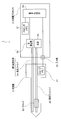
- FIG. 1 is a diagram showing a configuration of an endoscope system 1.
- the endoscope system 1 includes an endoscope 2 provided with an insertion portion to be inserted into a subject on the distal end side, an endoscope processor 3 to which the endoscope 2 is connected, It has.
- the endoscope 2 includes a scope memory 21, an irradiation optical fiber 22, a scanner 23, and a light receiving fiber 24, and is configured as a scanning endoscope.
- the scope memory 21 scans a detection signal (spiral data) obtained by receiving the return light of the irradiation light spot that scans the subject at a predetermined timing in a second orbit (a scanning orbit distorted according to the scope).
- a second mapping table corrected conversion table representing the correspondence between the second trajectory address (spiral address) and the second address (raster address) of the two-dimensional coordinates representing the position on the subject. Is.
- the scope memory 21 is a conversion table (mapping table) from the spiral address n to the raster address (x, y), and scans with the scanning trajectory of the irradiation light spot actually irradiated from the endoscope 2.
- a corrected conversion table ⁇ n ⁇ (x ′, y ′) ⁇ corresponding to the case where it is performed is stored in a nonvolatile manner and held.
- the actual scanning trajectory of the irradiation light spot generally deviates from the ideal scanning trajectory as designed due to manufacturing variations among the endoscopes 2. Further, even for the same individual, the scanning trajectory may change as the use period becomes longer. For this reason, in order to obtain an accurate image, it is necessary to perform calibration for correcting a conversion table (an ideal conversion table described later) as designed by performing actual measurement (for example, every predetermined period).
- a conversion table an ideal conversion table described later
- the corrected conversion table is information unique to each individual of the endoscope 2, for example, obtained by performing such calibration.
- FIG. 3 is a diagram showing an example of the spiral address n when the scanning trajectory performed by the scanner 23 has a spiral shape (spiral shape).
- the scanning is not limited to the spiral shape, and may be performed along an appropriate trajectory such as a concentric circle shape, a concentric rectangular shape, or a raster pattern shape.
- the scanning may be performed from the inner peripheral side to the outer peripheral side, or may be performed from the outer peripheral side to the inner peripheral side, Both may be performed alternately.
- the detection signal is obtained by receiving the return light of the irradiation light spot at every time interval that is rough on the outer periphery side, or on the contrary, every time interval that the inner periphery side is rough and every time interval that the outer periphery side is dense, etc.
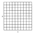
- FIG. 4 is a diagram showing an example of a raster address.
- the raster address is an address that sets an x-coordinate and a y-coordinate on two dimensions and gives a position in two dimensions by a combination (x, y) of the x and y coordinates.
- the x-coordinate and y-coordinate take discrete values, and are expressed using integers, for example.
- the irradiation optical fiber 22 transmits light supplied from a light source 33 described later to the distal end side of the endoscope 2 and irradiates the subject from the distal end with directivity.
- a light source 33 described later
- the irradiated light it is preferable to use, for example, a laser beam or the like which has a uniform phase and hardly spreads the wave packet.
- the irradiation light becomes an irradiation light spot with a limited irradiation area on the subject.
- the scanner 23 includes, for example, a plurality of piezoelectric elements that press the peripheral surface of the irradiation optical fiber 22 in different directions via a ferrule or the like, and controls the phase and amplitude of the voltage applied to the piezoelectric element, thereby irradiating the optical fiber.
- the direction in which the tip of 22 faces can be changed. Then, by changing the direction in which the tip of the irradiation optical fiber 22 faces, the subject is scanned with the irradiation light from the irradiation optical fiber 22.
- the light receiving fiber 24 forms a return light detection unit, receives the return light of the irradiation light spot that scans the subject at the distal end side, and transmits it to the proximal side of the endoscope 2.
- the light receiving fiber 24 is connected at its proximal end to a light detection unit 34 (to be described later) of the endoscope processor 3, and the light detection unit 34 detects return light.
- the endoscope processor 3 includes a processor memory 31, an input unit 32, a light source 33 (externally attachable), a light detection unit 34, and a signal processing unit 35.
- the processor memory 31 scans the detection signal (spiral data) obtained by receiving the return light of the irradiation light spot that scans the subject at a predetermined timing in the first orbit (ideal scanning orbit).
- a first mapping table (ideal conversion table) representing the correspondence between the first trajectory address (spiral address) and the first address (raster address) of the two-dimensional coordinates representing the position on the subject is held.
- the processor memory 31 is a conversion table (mapping table) from the spiral address n to the raster address (x, y), and the irradiation light spot emitted from the endoscope 2 is ideally scanned as designed.
- the ideal conversion table ⁇ n ⁇ (x, y) ⁇ corresponding to the case where scanning is performed by the trajectory is stored and held in a nonvolatile manner.
- This ideal conversion table is information unique to each model of the endoscope 2, for example.
- the input unit 32 is configured such that the above-described second mapping table (corrected conversion table) is input from the above-described scope memory 21 of the endoscope 2.
- This corrected conversion table is a raster address (x, y) that fills a two-dimensional subject discretely according to two-dimensional coordinates from a spiral address n that discretely fills the two-dimensional subject along the scanning trajectory. Since this is a table for performing conversion, the amount of data is relatively large and it takes a certain amount of time to read.
- the light source 33 emits light for use as irradiation light and supplies it to the proximal end side of the irradiation optical fiber 22, and includes, for example, a laser light source.
- a laser light source included in the endoscope processor 3
- the light source 33 is configured as a light source device independent of the endoscope processor 3 and connected to the endoscope 2. It doesn't matter.
- the light detection unit 34 constitutes a return light detection unit, detects return light of the irradiation light spot transmitted from the light receiving fiber 24 at a predetermined timing, and generates an electrical detection signal corresponding to the amount of return light. And output to the signal processing unit 35.
- the light detection unit 34 is arranged in the endoscope processor 3, but the configuration is not limited to this configuration. For example, it may be arranged in the operation part on the hand side of the endoscope 2 or may be separately arranged between the endoscope 2 and the endoscope processor 3.
- the signal processing unit 35 starts input of the second mapping table (corrected conversion table) in the first period, and based on the first mapping table (ideal conversion table) and the detection signal obtained in the first period.
- the first pixel signal (raster data) stored at the first address (raster address) is generated and obtained in the second mapping table and the second period in the second period after the input of the second mapping table is completed.
- the second pixel signal (raster data) stored at the second address (raster address) is generated.
- the signal processing unit 35 handles the detection signal input from the light detection unit 34 as spiral data associated with the spiral address n, and performs mapping processing based on a conversion table (ideal conversion table or corrected conversion table). Then, a two-dimensional image in which the detection signal is distributed to the raster address (x, y) is formed.
- the signal processing unit 35 in the present embodiment distributes detection signals based on a distribution table described later included in the conversion table, and weights linearly combines the detection signals based on a combination table described later included in the conversion table.
- the pixel signals constituting the image are calculated.
- the signal processing unit 35 can immediately refer to the information stored in the processor memory 31, but the information stored in the scope memory 21 cannot be referred to immediately because of the communication speed. . Therefore, the corrected conversion table stored in the scope memory 21 is temporarily stored in, for example, the processor memory 31 via the input unit 32 and the signal processing unit 35 and then referred to. The processing of the signal processing unit 35 will be described in more detail with reference to FIG.
- FIG. 2 is a flowchart showing the operation of the endoscope processor 3.
- the signal processor 35 of the endoscope processor 3 reads a corrected conversion table (for example, a distribution table as shown in FIG. 9 and a synthesis table as shown in FIG. 10) from the scope memory 21 via the input unit 32. Is started (step S1).
- a corrected conversion table for example, a distribution table as shown in FIG. 9 and a synthesis table as shown in FIG. 10.
- the following steps S2 and S3 are performed in parallel with the reading process of the corrected conversion table.
- the subject is scanned by changing the direction of the tip of the irradiation optical fiber 22 by the scanner 23 while emitting light from the light source 33 and irradiating the irradiation light from the tip of the irradiation optical fiber 22.
- the light receiving fiber 24 receives the return light of the irradiation light from the subject and transmits it to the light detection unit 34.
- the light detection unit 34 detects the return light at a predetermined timing and generates a detection signal.
- the detection signal generated at a predetermined timing is read into the signal processing unit 35 as spiral data (step S2).
- the signal processing unit 35 refers to the ideal conversion table held in the processor memory 31, maps the spiral data to the raster address (x, y), and generates raster data (step S3).
- the conversion table (ideal conversion table and corrected conversion table) used in this embodiment is a distribution table (FIG. 7 shows an example in the case of an ideal conversion table, and FIG. 9 shows an example in the case of a corrected conversion table).
- a synthesis table FIG. 8 shows an example of an ideal conversion table, and FIG. 10 shows an example of a corrected conversion table).
- the first mapping table (ideal conversion table) includes a plurality of first addresses (raster addresses) to which a first trajectory address (spiral address) and a detection signal (spiral data) associated with the first trajectory address are distributed. And a synthesis table representing the correspondence between the first address and the weight of the detection signal distributed to the first address.
- the second mapping table (corrected conversion table) includes a plurality of second addresses (raster addresses) to which a second trajectory address (spiral address) and a detection signal (spiral data) associated with the second trajectory address are distributed. ) And a synthesis table representing the correspondence between the second address and the weight of the detection signal distributed to the second address.
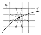
- FIG. 5 is a diagram showing how a detection signal of a certain spiral address is distributed to a plurality of raster addresses.
- one point indicated by a spiral address n on the scanning trajectory forming the spiral curve SC does not always overlap with one point indicated by the raster address (x, y) in the raster coordinates RC. .
- one point indicated by the spiral address n is located between a plurality of points indicated by a plurality of raster addresses (x, y).
- a plurality of detection signals acquired at a certain spiral address n are positioned around the position indicated by the spiral address n.
- the raster data is preferably obtained by weighted addition based on the spiral data of a plurality of spiral addresses n located around the corresponding raster address (x, y).
- FIG. 5 shows, as an example of such distribution, how a detection signal associated with one spiral address n is distributed to 12 surrounding raster addresses (x, y).
- the distribution table shown in FIGS. 7 and 9 represents the correspondence between the spiral address n at this time and a plurality of distribution destination raster addresses (x, y) to which the detection signals are distributed. Note that the number (r + 1) of distribution destination raster addresses does not have to be the same for all spiral addresses n, and may differ depending on the spiral address n.
- FIG. 7 is a diagram illustrating an example of a distribution table of an ideal conversion table
- FIG. 9 is a diagram illustrating an example of a distribution table of a corrected conversion table.
- the distribution table of the ideal conversion table shown in FIG. 7 and the distribution table of the corrected conversion table shown in FIG. 9 have basically the same table structure, but the contents of the addresses arranged in the table are different. Yes.
- the raster address (i, j) corresponding to the spiral address n in the ideal scanning trajectory as designed is stored, but in the case of FIG. 9, it is obtained by the calibration described above.
- the raster address (i ′, j ′) is stored.
- the number of distribution destination raster addresses (r + 1) corresponding to a certain spiral address n is generally not the same between the distribution table of the ideal conversion table and the distribution table of the corrected conversion table.
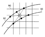
- FIG. 6 is a diagram showing a state in which a plurality of detection signals acquired at a plurality of spiral addresses n are distributed to a certain raster address (x, y).
- a spiral curve is present at a raster address (x, y) indicated by the raster coordinates RC.
- a plurality of detection signals acquired at a plurality of spiral addresses n on the scanning trajectory forming the SC are distributed.
- FIG. 6 shows, as an example of such distribution, raster data stored at one raster address (x, y) is configured based on spiral data distributed from six surrounding spiral addresses n. It shows a state.
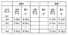
- the composite table shown in FIGS. 8 and 10 represents the correspondence between the raster address (x, y) at this time and the weights of the plurality of detection signals distributed to the raster address (x, y). .
- FIG. 8 is a diagram showing an example of a synthesis table of ideal conversion tables
- FIG. 10 is a diagram showing an example of a synthesis table of corrected conversion tables.
- the maximum number of detection signals (number of elements) distributed to a certain raster address (x, y) is 8 (that is, element 0 to element 7).
- the present invention is not limited to this.
- the number of elements of all raster addresses (x, y) is not necessarily the same.
- the number of elements of a certain raster address (x, y) is 8, but the number of elements of another raster address (x, y) is 7, and so on.
- the synthesis table of the ideal conversion table shown in FIG. 8 and the synthesis table of the corrected conversion table shown in FIG. 10 have basically the same table structure, but the contents of the distributed data arranged in the table. And the contents of the weights are different.
- the distributed data and weight the distributed data is acquired at the time of shooting, and therefore only the weight is stored in the scope memory 21 or the processor memory 31 in a non-volatile manner (therefore,
- the scope memory 21 inputs to the input unit 32 is a portion excluding the “distributed data” column in the distribution table shown in FIG. 9 and the synthesis table shown in FIG.
- the content of the distributed data is different because the content of the distribution destination raster address described in the distribution table is different between FIG. 7 and FIG. 9, which spiral data at a certain raster address (x, y). This is because the distribution is different.
- the weights are different for the following reasons. That is, when forming a pixel signal of a raster address (x, y) based on a plurality of spiral data, as shown in FIG. 6, spiral data whose distance is close to the raster address (x, y) of interest is Since the correlation is higher than that of spiral data at a long distance, the weight is set to be heavier. Since the ideal conversion table and the corrected conversion table have different assumed shapes of the spiral curve SC, the positional relationship between the raster address (x, y) and the spiral data is also different and the weighting is different. It is.
- the weight W corresponding to the ideal scanning trajectory as designed is stored, but in the case of FIG. 10, the weight W ′ acquired by the calibration described above is stored. ing.
- the number of elements corresponding to a certain raster address (x, y) is generally not the same between the synthesis table of the ideal conversion table and the synthesis table of the corrected conversion table.
- the signal processing unit 35 uses the ideal conversion table distribution table as shown in FIG. 7 and the ideal conversion table synthesis table as shown in FIG. 8, the signal processing unit 35 performs the following processing in step S3.
- the signal processing unit 35 obtains distribution destination raster addresses 0 to r corresponding to the spiral address n by referring to the column of the spiral address n in the distribution table of FIG. To do.
- the signal processing unit 35 distributes the spiral data of the spiral address n by copying it to the “distributed data” column of the element corresponding to each of the distribution destination raster addresses 0 to r in the synthesis table of FIG. To do. At this time, if there is an element in which spiral data has already been copied among the elements 0 to 7, the spiral data is copied to the element having the smallest element number among the elements to which the spiral data has not been copied yet. .
- the signal processing unit 35 calculates the first pixel signal by weighted linearly combining the detection signals based on the synthesis table. That is, if the elements 0 to 7 are represented by k, the raster data D (x, y), which is the first pixel signal stored at the raster address (x, y), is expressed by the following formula 1. .
- Equation 1 the weight W is normalized as shown in Equation 2 below.
- the image thus configured is displayed on a monitor (not shown) connected to the endoscope processor 3 or recorded on a recording device (not shown) connected to the endoscope processor 3.
- step S4 the signal processing unit 35 determines whether or not the reading of the corrected conversion table started in step S1 is completed. If it has not been completed yet, while continuing to read the corrected conversion table, the process returns to step S2 described above to read the spiral data relating to the next frame.
- step S4 if it is determined in step S4 that reading of the corrected conversion table has been completed, the first period in which mapping was performed using the ideal conversion table is ended, and mapping is performed using the corrected conversion table. Enter the second period.
- spiral data is read in the same manner as in step S2 (step S5).
- the signal processing unit 35 finishes reading, refers to the corrected conversion table stored in the processor memory 31, for example, maps the spiral data, and generates raster data (step S6).
- step S6 is the same as the process in step S3 described above except that a corrected conversion table is used instead of the ideal conversion table.
- the signal processing unit 35 calculates the second pixel signal by weighted linearly combining the detection signals based on the synthesis table. That is, the signal processing unit 35 converts the raster data D ′ (x, y), which is the second pixel signal stored at the raster address (x, y), into the following Expression 3 in the same manner as Expression 1 described above. By performing the calculation as shown for all the raster addresses (x, y), an image of one frame is constructed.
- Equation 3 It should be noted that the weight W ′ is normalized as shown in the following Equation 4 as in the case of the ideal conversion table.
- step S7 it is determined whether or not the photographing is finished (step S7), and if not finished, the process returns to the above-described step S5 to read the spiral data related to the next frame.
- the second period in which mapping is performed using the corrected conversion table ends, and this process ends.
- the input of the second mapping table (corrected conversion table) from the input unit 32 is started and the first mapping table (ideal ideal) held in the processor memory 31 is started. Since the first pixel signal (raster data) stored at the first address (raster address) is generated based on the conversion table) and the detection signal obtained in the first period, the second mapping table (correction) Without waiting for the reading of the (conversion completed conversion table) to be completed, it is possible to start up and display an image within a short time after the power is turned on.
- the second mapping table (corrected conversion table) and the detection signal obtained in the second period are used for the second period. Since the second pixel signal (raster data) stored at the address (raster address) is generated, a more accurate image can be displayed in the second period.
- the second mapping table represents the correspondence between the second trajectory address (spiral address) and a plurality of second addresses (raster addresses) to which detection signals are distributed.
- a distribution table see FIG. 9
- a synthesis table representing the correspondence between the second address and the weight of the detection signal distributed to the second address, and will be described in, for example, a second embodiment to be described later
- the amount of data is much larger. Therefore, since it takes a longer time to read from the scope memory 21, it is possible to achieve a higher effect by adopting a configuration using the first mapping table (ideal conversion table) in the first period.
- the signal processing unit 35 calculates the second pixel signal (raster data) by distributing the detection signal based on the distribution table and weighted linearly combining the detection signal based on the synthesis table, Processing can be performed based on table reference and simple operations such as multiplication and addition, and an image can be obtained at high speed with a small processing load.
- the endoscope 2 scans with the irradiation light spot to receive the return light from the subject, and the input unit 32 receives the second mapping table (corrected conversion table) from the scope memory 21 provided in the endoscope 2. Therefore, in the endoscope system 1, it is possible to shorten the start-up time while enabling accurate endoscopic image display.
- the scope memory 21 provided in the endoscope 2 stores the second mapping table and the endoscope 2 is connected to the endoscope processor 3, the second mapping table is input. In addition, the combination of the endoscope 2 and the second mapping table can be ensured.
- FIG. 11 and 12 show Embodiment 2 of the present invention.
- FIG. 11 shows an example of an ideal conversion table
- FIG. 12 shows an example of a corrected conversion table.
- one spiral data is distributed to a plurality of raster addresses (x, y), and conversely, one raster data is a plurality of spirals. It was made up of data.
- one spiral address n is simplified corresponding to only one raster address (x, y), and a mapping conversion table is created. .
- both the ideal conversion table shown in FIG. 11 and the corrected conversion table shown in FIG. 12 are tables showing the correspondence between the spiral address n and the raster address (x, y).
- the contents of the raster address (x, y) corresponding to the spiral address n that is, the address value stored in the raster address (x, y).
- the raster address (x, y) (x′0, y′0) is stored.
- the first mapping table (ideal conversion table) has a one-to-one correspondence between the first trajectory address (spiral address n) and the first address (raster address (x, y)). It is a table showing.
- the signal processing unit 35 uses the detection signal obtained in association with the first trajectory address (spiral address) as the first pixel signal (first address (raster address)) corresponding to the first trajectory address (spiral address). Raster data).
- the second mapping table (corrected conversion table) has a one-to-one correspondence between the second trajectory address (spiral address n) and the second address (raster address (x, y)). It is a table showing a relationship.
- the signal processing unit 35 uses the detection signal obtained in association with the second trajectory address (spiral address) as the second pixel of the second address (raster address) corresponding to the second trajectory address (spiral address). Set as a signal (raster data).
- the process of weighted linear combination of the detection signals is not required, and the weighting column is not required in either the ideal conversion table or the corrected conversion table.
- the spiral data is arranged at the raster address (x, y) corresponding to the spiral address n on a one-to-one basis
- the spiral data is arranged at the raster address (x, y) not associated with the spiral address n. Will not be.
- the signal processing unit 35 stores it at addresses around the first address (raster address) (raster address).
- An interpolation signal is calculated using the first pixel signal (raster data), and the interpolation signal is stored in a first address (raster address).
- the signal processing unit 35 stores the second pixel signal (raster address) at an address (raster address) around the second address (raster address).
- An interpolation signal is calculated using the second pixel signal (raster data), and the interpolation signal is stored in a second address (raster address).
- an image in which the signal values of all raster addresses (x, y) (including the case where the signal values are 0) is defined.
- interpolation processing is not essential.
- a process of giving a signal value of 0 may be performed on the raster address (x, y) where no signal is arranged.
- the first mapping table (ideal conversion table) is used as a table representing a one-to-one correspondence between the first trajectory address (spiral address) and the first address (raster address).
- the signal processing unit 35 uses the detection signal obtained in association with the first trajectory address (spiral address) as the first pixel signal (raster data) of the first address (raster address) corresponding to the first trajectory address (spiral address). ),
- the time lag at start-up until the first image of the first frame can be displayed after the power is turned on becomes unnecessary from the above-described first embodiment. Can also be shortened. In each frame, the time lag from when scanning is performed until the frame image can be displayed can be shortened as compared with the first embodiment.
- the signal processing unit 35 uses the second mapping table (corrected conversion table) as a table representing a one-to-one correspondence between the second trajectory address (spiral address) and the second address (raster address).
- the second mapping table corrected conversion table
- the detection signal obtained in association with the second trajectory address (spiral address) as the second pixel signal (raster data) of the second address (raster address) corresponding to the second trajectory address (spiral address).
- the second mapping table (corrected conversion table) is a table indicating a one-to-one correspondence between the second trajectory address (spiral address) and the second address (raster address), so that the corrected conversion table is used. Can be made smaller than the corrected conversion table of the first embodiment described above, and the time until the second period is shifted can be shortened. Therefore, it is possible to observe an accurate image earlier. Further, the storage capacity required for the scope memory 21 can be reduced.
- the signal processing unit 35 calculates the interpolation signal using the raster data) and stores the interpolation signal at the first address (raster address), the signal value changes smoothly, and an image with a more natural appearance is obtained. Can be configured.
- This embodiment is an intermediate embodiment between the first embodiment and the second embodiment described above.
- this embodiment uses the conversion table as shown in FIG. 11 of the above-described second embodiment as the ideal conversion table, for example, as shown in FIG. 9 and FIG. 10 of the above-described first embodiment as the corrected conversion table.
- the table set as shown is used.
- the startup time lag until the first frame image can be displayed after the power is turned on, and the frame image can be displayed after scanning in the first period. It is possible to shorten the time lag until the time becomes until the second embodiment described above, and it is possible to obtain an accurate image similar to the first embodiment described above in the second period.
- FIG. 13 is a diagram illustrating an example of RAW data according to the fourth embodiment of the present invention.
- the endoscope processor 3 can output spiral data before being converted into display raster data as RAW data.
- the RAW data is data having a configuration as shown in FIG. 13, for example.
- the raster address (x, y) in the above-described embodiment is an address based on pixels constituting the image (for example, an address in units of the pixel pitch in the x direction and the pixel pitch in the y direction).
- the raster address (X, Y) stored in the RAW data is an address representing the spiral address n on a two-dimensional coordinate.
- the raster address (x, y) is an address for storing an integer value, for example, while the raster address (X, Y) is generally an address for storing a real value.
- a decimal number with a significant number of digits according to the measurement accuracy of the measuring instrument is stored in the raster address (X, Y). Is done.
- the RAW data is output from the endoscope processor 3 and recorded, for example, in a recording device. Accordingly, at a desired time, a display image can be configured by reading RAW data from the recording apparatus into a separate image processing apparatus and performing image processing.
- monitors with various pixel configurations exist for monitors that display images.
- the spiral pixel D (n) is stored in any display pixel (1) for an arbitrary monitor. It is possible to calculate whether to distribute to one or a plurality of display pixels.
- the raster address (Xn, Yn) is a precise address described in, for example, a real number, the positional relationship of which display pixel corresponds to the spiral address n is accurately calculated, and accurate weighting is performed. Can also be performed.
- the same effects as those of the first to third embodiments described above are obtained, and the endoscope processor 3 outputs the RAW data, so that a separate image can be obtained at a desired time.
- Image processing can be performed by the processing device. Thereby, it becomes possible to perform precise image display on an arbitrary display device without depending on a specific display device.
- a transition period is provided between the end of the first period after the input of the second mapping table (corrected conversion table) is completed and the start of the second period. It has become.
- this transition period for example, an intermediate image between the image configured in the first period and the image configured in the second period is configured.
- the signal processing unit 35 performs an image synthesis process in the transition period, and generates an image including both the first pixel signal (raster data) and the second pixel signal (raster data). ing.
- the source of the first pixel signal and the second pixel signal used for image synthesis at this time includes, for example, the following.
- mapping is performed using a first period during which mapping is performed using a first mapping table (ideal conversion table) and an image is acquired, and a second mapping table (corrected conversion table) for which input has been completed.
- mapping is performed using the second mapping table (corrected conversion table) in the same manner as in the second period, and an image is generated.
- a first pixel signal that constitutes an image obtained in the last frame of the first period and a second image signal that constitutes an image of the latest frame obtained using the corrected conversion table Using this, image synthesis processing is performed to generate an image including both the first pixel signal and the second pixel signal.
- the second pixel signal needs to be calculated by performing mapping. Since it is not necessary to newly calculate, an increase in processing load can be avoided.
- the first image signal is generated by mapping the spiral data using the first mapping table (ideal conversion table) in the transition period after the end of the first period. Both the generation of the second image signal by mapping the spiral data using the second mapping table (corrected conversion table) for which the input has been completed are performed for each frame.
- image synthesis processing is performed using the first pixel signal and the second pixel signal generated based on the spiral data of the same frame, and an image including both the first pixel signal and the second pixel signal is generated. is there.
- the first pixel signal used for the image synthesis process And the second pixel signal are generated based on the detection signal at the same acquisition time point, so that the first pixel signal and the second pixel generated based on the detection signal at different acquisition time points as in the first example described above There is an advantage that no mismatch occurs when a signal is used.
- the first image signal is generated by mapping the spiral data using the first mapping table (ideal conversion table) in the transition period after the end of the first period;
- the second image signal is generated by mapping the spiral data using the second mapping table (corrected conversion table) for which the input has been completed, for example, alternately for each frame.
- image synthesis processing is performed using the first pixel signal related to one frame and the second pixel signal related to the other frame of the latest frame and the latest previous frame, An image including both the pixel signal and the second pixel signal is generated.
- the third example since there is only one type of conversion table used when generating one frame image, an increase in processing load can be avoided, and the first pixel signal and the first pixel signal used for image composition processing can be avoided. Since the two-pixel signal relates to an adjacent frame, there is an advantage that mismatch between the first pixel signal and the second pixel signal due to a difference in detection signal acquisition time can be suppressed.
- the frame ratio of the ideal conversion table may be increased at a time close to the first period during the transition period, and the frame ratio of the corrected conversion table may be increased at a time close to the second period.
- the scanning trajectory has a spiral shape
- every time the frame is switched for example, the region of the second pixel signal is enlarged in a spiral shape from the inner peripheral side.
- the image may be configured to be filled with two pixel signals.
- a display in which the area of the first pixel signal is gradually replaced with the area of the second pixel signal in a form according to the scanning trajectory is performed.
- the period of the voltage applied to the piezoelectric element is made constant (however, the amplitude is changed) and spiral scanning as shown in FIG. 3 is performed, that is, either on the inner peripheral side or the outer peripheral side.
- the time required for the scanning trajectory to rotate 360 degrees and advance is the same, and the detection signal is acquired at regular time intervals
- the density of the acquired spiral data is The higher it is, the lower it goes to the outer periphery.
- an important subject is often located at the center of the image. From this point of view, it is preferable to perform a process in which the inner peripheral side is first repainted with the second pixel signal region.
- the repainting from the first pixel signal region to the second pixel signal region is not limited to the spiral shape, and may be performed sequentially in an annular shape from the center portion to the outer peripheral portion.
- a method according to the movement of the wiper may be used, or any other method may be adopted as long as it is a method that does not cause a visually uncomfortable feeling.
- the same effects as those of the first to fourth embodiments described above can be obtained, and a transition period is provided between the end of the first period and the start of the second period. Since the image including both the first pixel signal related to the ideal conversion table and the second pixel signal related to the corrected conversion table is generated in the transition period, the image when switching from the first period to the second period It is possible to reduce a sense of incongruity due to change.
- FIG. 14 shows Embodiment 6 of the present invention and is a diagram showing an example of a conversion table.
- the conversion table having the structure shown in FIG. 14 can be applied to both the ideal conversion table and the corrected conversion table.
- the conversion table of FIG. 14 obtains the same conversion result as the ideal conversion table shown in FIGS. 7 and 8 of the first embodiment described above or the corrected conversion table shown in FIGS. 9 and 10. It is configured as a table that can.
- the pixel configuration is 1920 horizontal pixels ⁇ 1080 vertical pixels, and the total number of pixels is about 2 million pixels.
- the number of data acquired by spiral data differs depending on the scanning method, but in order to display it as a full HD image, a number of detection signals close to the total number of pixels of the full HD image are required. Spiral data is required. Therefore, if an array of several hundred thousand ⁇ 2 million is configured and weights for multiplying the spiral data are arranged at necessary portions in the array, a conversion table can be configured.
- the distribution destination raster address corresponding to the spiral address n can be acquired immediately, and the empty element of the acquired distribution destination raster address in the synthesis table If spiral data is arranged on the screen, a combination of spiral data and weight necessary for calculating raster data is automatically completed. Therefore, an image to be obtained can be formed by weighted linear combination of the detection signals based on the obtained synthesis table, which is an excellent systematic structure.
- the conversion table of the first embodiment is composed of a plurality of tables (distribution table and synthesis table).
- the conversion table of the present embodiment is configured so that mapping can be performed with one table.
- the maximum number of elements indicating how many raster addresses correspond to each other is set to 8 (that is, elements 0 to 7) (that is, similar to the example shown in FIGS. 8 and 10). is there).
- the maximum number of elements is not limited to eight.
- the weight W ′′ k (x, y) is determined based on the distance between the raster address (x, y) and the spiral address nk (x, y), similarly to the weights W and W ′ of the first embodiment.
- the normalized values are obtained as shown in Equation 5 below.
- spiral data D ′′ k (x, y) which is a detection signal acquired at the spiral address nk (x, y)
- the spiral data D ′′ k (x, y) in the “distributed data” column is acquired at the time of shooting and is held in the scope memory 21 or the processor memory 31 in a nonvolatile manner. It is not data.
- the total of the number of elements of the spiral address 8 and the number of elements of the weight W ′′ is 16. Therefore, the number of elements corresponding to the above case is 2 million ⁇ 16-3.
- the number of elements can be reduced to tens of thousands compared to a simple conversion table having an array of several hundred thousand ⁇ 2 million, almost the same as in the first embodiment, and the table is compact. And the amount of data can be greatly reduced.
- the signal processing unit 35 performs the following processing in step S3 and step S6 shown in FIG. 2 using the conversion table shown in FIG.
- the signal processing unit 35 searches all the items that match the target spiral address n from all the spiral address fields in the conversion table of FIG. The spiral data at the spiral address n is copied in the “distributed data” field.
- the “distributed data” column in the conversion table of FIG. 14 is filled, and the detection signal for one frame is accumulated.
- the image thus configured is displayed on the monitor or recorded on the recording device in the same manner as described above.
- the corrected conversion table is stored in the scope memory 21 of the endoscope 2, and the input unit 32 of the endoscope processor 3 reads the corrected conversion table from the scope memory 21.
- the present invention is not limited to this.
- a corrected conversion table for each of the two endoscopes (latest if calibration is performed periodically) is stored in a nonvolatile memory on a network such as a hospital network, and the endoscope processor 3 stores the corrected conversion table.
- the operation may be performed in which the input unit 32 of the endoscope processor 3 reads a necessary corrected conversion table from the network.
- each part mentioned above may be constituted as a circuit.
- Any circuit may be mounted as a single circuit or a combination of a plurality of circuits as long as it can perform the same function.
- an arbitrary circuit is not limited to being configured as a dedicated circuit for performing a target function, and may be configured to perform a target function by causing a general-purpose circuit to execute a processing program. .
- the endoscope processor and the endoscope system are mainly described.
- an operation method for operating the endoscope processor or the endoscope system as described above may be used.
- it may be a processing program for performing the same processing as that of the endoscope system, a non-temporary recording medium readable by a computer that records the processing program, and the like.
- the present invention is not limited to the above-described embodiment as it is, and can be embodied by modifying the constituent elements without departing from the scope of the invention in the implementation stage.
- various aspects of the invention can be formed by appropriately combining a plurality of components disclosed in the embodiment. For example, you may delete some components from all the components shown by embodiment.
- the constituent elements over different embodiments may be appropriately combined.
Landscapes
- Health & Medical Sciences (AREA)
- Life Sciences & Earth Sciences (AREA)
- Surgery (AREA)
- Physics & Mathematics (AREA)
- Optics & Photonics (AREA)
- Medical Informatics (AREA)
- Animal Behavior & Ethology (AREA)
- Radiology & Medical Imaging (AREA)
- Nuclear Medicine, Radiotherapy & Molecular Imaging (AREA)
- Engineering & Computer Science (AREA)
- Biomedical Technology (AREA)
- Heart & Thoracic Surgery (AREA)
- Biophysics (AREA)
- Molecular Biology (AREA)
- Pathology (AREA)
- General Health & Medical Sciences (AREA)
- Public Health (AREA)
- Veterinary Medicine (AREA)
- Astronomy & Astrophysics (AREA)
- General Physics & Mathematics (AREA)
- Endoscopes (AREA)
- Instruments For Viewing The Inside Of Hollow Bodies (AREA)
- Mechanical Optical Scanning Systems (AREA)
- Mechanical Light Control Or Optical Switches (AREA)
Abstract
第1軌道アドレスと2次元アドレスとの対応関係を表す第1変換テーブルを保持するプロセッサメモリ(31)と、第2軌道アドレスと2次元アドレスとの対応関係を表す第2変換テーブルが入力される入力部(32)と、第2変換テーブルを入力中の第1期間に第1変換テーブルおよび検出信号に基づいて2次元アドレスに格納される画素信号を生成し、入力完了後の第2期間に第2変換テーブルおよび検出信号に基づいて2次元アドレスに格納される画素信号を生成する信号処理部(35)と、を有する内視鏡プロセッサ(3)。
Description
本発明は、被写体を走査する照射光スポットの戻り光を受光して画像を生成する内視鏡プロセッサ、内視鏡システムに関する。
被写体を走査する照射光スポットの戻り光を受光して画像を生成する内視鏡プロセッサ、およびこの内視鏡プロセッサを含む内視鏡システムは、従来より走査型内視鏡システムとして提案されている。
すなわち、医療分野等に用いられる内視鏡においては、被検者の負担を軽減するために挿入部を細径化する種々の技術が提案されている。このような技術の一例として、挿入部に固体撮像素子を有しない走査型内視鏡を備える走査型内視鏡システムが知られている。
走査型内視鏡システムは、例えば、以下のような方法で画像を構成している。
まず、照射光スポットを被写体へ照射して、例えばスパイラル状(渦巻状)の走査軌道で走査する。
そして、離散化された時刻における走査軌道上の照射光スポットからの戻り光を検出して、検出信号を生成する。ここで、各時刻において検出された検出信号は、走査軌道上の位置を示すスパイラルアドレス(n=0,1,2,…,m)にそれぞれ一対一に関連付けられている。
さらに、スパイラルアドレスと直交座標との対応関係に基づいて、各時刻において検出された検出信号を、直交座標で表される画面上の点(ラスタアドレス(x,y)=(0,0),(0,1),(0,2),…,(p,q)で示される点)にそれぞれマッピングする。これにより、2次元の画像が構成される。
しかし、走査型内視鏡が実際に使用される際の走査軌道は、一般に、設計値などから定められる理想的な走査軌道から外れている。従って、理想的な走査軌道に準拠したマッピングを行うと、画像に歪みが生じるなどして、正確な画像を得ることができない。
そこで、例えば日本国特許第5190267号公報には、理想から外れた走査軌道で走査して得られる検出信号を補正するキャリブレーション技術が記載されている。すなわち、該公報に記載の技術では、まず、スパイラルアドレスnからラスタアドレス(x,y)への理想的な変換テーブル{n→(x,y)}をキャリブレーションすることにより、補正済の変換テーブル{n→(x’,y’)}を作成する。そして、この補正済の変換テーブル{n→(x’,y’)}を用いて検出信号をラスタアドレス(x,y)に配置する(マッピングする)ことにより、正確な画像を得るようになっている。
ところで、実際の走査軌道が理想的な走査軌道からどのように外れるかは、走査型内視鏡の機種毎に異なるだけでなく、走査型内視鏡の個体毎にも異なる。従って、上述した日本国特許第5190267号公報の技術を用いて正確な画像を構成しようとすると、補正済の変換テーブルを内視鏡の個体毎に生成する必要がある。検出信号をマッピングして画像を構成する処理は、内視鏡に接続される内視鏡プロセッサで行われるが、内視鏡と内視鏡プロセッサとは様々に組み合わせられるために、全ての機種および各機種における全ての個体の補正済の変換テーブルを内視鏡プロセッサが予め保持しておくことは現実的でない。
そこで、補正済の変換テーブルは、例えば内視鏡内のメモリに記憶しておき、内視鏡プロセッサが、接続されている内視鏡のメモリから読み込むという運用法が実用的である。
しかし、マッピング用の変換テーブルのデータ量は、戻り光のサンプリング数、つまり、スパイラルアドレスnの最大数mに比例するが、小さな照射光スポットで画面を埋め尽くすために必要な戻り光のサンプリング数mは、一般に膨大な数になる。その結果、マッピング用の変換テーブルのデータ量も膨大となり、読み込みに時間がかかることから、電源をオンしてから画像を表示できるまでの起動時間が長くなってしまう。
本発明は上記事情に鑑みてなされたものであり、正確な画像表示を可能としながら起動時間の短縮を図ることができる内視鏡プロセッサ、内視鏡システムを提供することを目的としている。
本発明のある態様による内視鏡プロセッサは、被写体を走査する照射光スポットの戻り光を所定のタイミングで受光して得られる検出信号の、前記走査を第1軌道で行った場合の第1軌道アドレスと、前記被写体上の位置を表す2次元座標の第1アドレスと、の対応関係を表す第1マッピングテーブルを保持するように構成されるプロセッサメモリと、前記検出信号の、前記走査を第2軌道で行った場合の第2軌道アドレスと、前記被写体上の位置を表す2次元座標の第2アドレスと、の対応関係を表す第2マッピングテーブルが入力されるように構成される入力部と、第1期間において、前記第2マッピングテーブルの入力を開始すると共に、前記第1マッピングテーブルおよび前記第1期間において得られた前記検出信号に基づいて、前記第1アドレスに格納される第1画素信号を生成し、前記第2マッピングテーブルの入力が完了した後の第2期間において、前記第2マッピングテーブルおよび前記第2期間において得られた前記検出信号に基づいて、前記第2アドレスに格納される第2画素信号を生成するように構成される信号処理部と、を有する。
本発明のある態様による内視鏡システムは、上記内視鏡プロセッサと、前記照射光スポットにより走査を行って、前記被写体からの前記戻り光を受光するように構成される内視鏡と、前記内視鏡に設けられ、前記第2マッピングテーブルを記憶するように構成されるスコープメモリと、を有し、前記入力部は、前記スコープメモリから前記第2マッピングテーブルを入力する。
以下、図面を参照して本発明の実施の形態を説明する。
[実施形態1]
図1から図10は本発明の実施形態1を示したものであり、図1は内視鏡システム1の構成を示す図である。
図1から図10は本発明の実施形態1を示したものであり、図1は内視鏡システム1の構成を示す図である。
内視鏡システム1は、図1に示すように、被写体に挿入される挿入部が先端側に設けられた内視鏡2と、この内視鏡2が接続される内視鏡プロセッサ3と、を備えている。
内視鏡2は、スコープメモリ21と、照射光ファイバ22と、スキャナ23と、受光ファイバ24と、を備え、走査型の内視鏡として構成されている。
スコープメモリ21は、被写体を走査する照射光スポットの戻り光を所定のタイミングで受光して得られる検出信号(スパイラルデータ)の、走査を第2軌道(スコープに応じて歪んだ走査軌道)で行った場合の第2軌道アドレス(スパイラルアドレス)と、被写体上の位置を表す2次元座標の第2アドレス(ラスタアドレス)と、の対応関係を表す第2マッピングテーブル(補正済変換テーブル)を保持するものである。
具体的にスコープメモリ21は、スパイラルアドレスnからラスタアドレス(x,y)への変換テーブル(マッピングテーブル)であって、内視鏡2から実際に照射される照射光スポットの走査軌道で走査を行った場合に対応する補正済変換テーブル{n→(x’,y’)}を不揮発に記憶して保持する。
すなわち、実際の照射光スポットの走査軌道は、内視鏡2の個体毎の製造バラツキによって、一般的には、設計通りの理想的な走査軌道から外れる。さらに同一個体であっても、使用期間が長くなるにつれて走査軌道が変化することがある。このために、正確な像を得るには、(例えば所定の期間毎に)実測等を行って、設計通りの変換テーブル(後述する理想変換テーブル)を補正するキャリブレーションを行う必要がある。
補正済変換テーブルは、こうしたキャリブレーションを行って得られた、例えば内視鏡2の個体毎に固有の情報である。
ここで、図3は、スキャナ23により行われる走査の軌道が、スパイラル状(渦巻状)をなす場合のスパイラルアドレスnの例を示す図である。ただし、走査は、スパイラル状に行うに限るものではなく、同心円状、同心矩形状、ラスタパターン状、などの適宜の軌道に沿って行っても構わない。
また、図3に示すようなスパイラル状の走査軌道の例において、走査は、内周側から外周側へ向けて行っても良いし、外周側から内周側へ向けて行っても良いし、両方を交互に行っても構わない。
例えば、走査を内周側から外周側へ向けて行う場合に、開始点Aをスパイラルアドレスn=0として、後述するように、所定のタイミング(例えば、一定の時間間隔毎、あるいは内周側が密な時間間隔毎で外周側が粗な時間間隔毎、または逆に内周側が粗な時間間隔毎で外周側が密な時間間隔毎、等)で照射光スポットの戻り光が受光されて検出信号が得られ、各タイミングで検出信号が得られた走査軌道上の位置がスパイラルアドレスn=0,1,2,…,mとなる。ここに、終了点Bが最後のスパイラルアドレスn=mである。
また、図4はラスタアドレスの例を示す図である。ラスタアドレスは、2次元上にx座標およびy座標を設定して、x座標とy座標の組み合わせ(x,y)により2次元における位置を与えるアドレスである。画像が画素を単位として構成されているのに対応して、x座標およびy座標は離散的な値をとり、例えば整数を用いて表現される。
照射光ファイバ22は、後述する光源33から供給された光を、内視鏡2の先端側へ伝送して、先端から被写体へ指向性をもって照射する。ここに、照射される光(照射光)は、例えばレーザ光などの、位相が揃っていて波束が広がり難い光を用いることが好ましい。これにより照射光は、被写体上における照射領域が限定された照射光スポットとなる。
スキャナ23は、例えば、フェルール等を介して照射光ファイバ22の周面を異なる方向へ押圧する複数の圧電素子を備え、圧電素子に印加する電圧の位相や振幅を制御することで、照射光ファイバ22の先端が向く方向を変化させることができるようになっている。そして、照射光ファイバ22の先端が向く方向が変化することで、照射光ファイバ22からの照射光による被写体の走査が行われる。
受光ファイバ24は、戻り光検出部を構成し、被写体を走査する照射光スポットの戻り光を先端側で受光して、内視鏡2の手元側へ伝送する。この受光ファイバ24は、基端側が内視鏡プロセッサ3の後述する光検出部34に接続されており、光検出部34により戻り光の検出が行われるようになっている。
次に、内視鏡プロセッサ3は、プロセッサメモリ31と、入力部32と、光源33(外付け可)と、光検出部34と、信号処理部35と、を備えている。
プロセッサメモリ31は、被写体を走査する照射光スポットの戻り光を所定のタイミングで受光して得られる検出信号(スパイラルデータ)の、走査を第1軌道(理想的な走査軌道)で行った場合の第1軌道アドレス(スパイラルアドレス)と、被写体上の位置を表す2次元座標の第1アドレス(ラスタアドレス)と、の対応関係を表す第1マッピングテーブル(理想変換テーブル)を保持するものである。
具体的にプロセッサメモリ31は、スパイラルアドレスnからラスタアドレス(x,y)への変換テーブル(マッピングテーブル)であって、内視鏡2から照射される照射光スポットが設計通りの理想的な走査軌道により走査を行った場合に対応する理想変換テーブル{n→(x,y)}を不揮発に記憶して保持する。この理想変換テーブルは、例えば内視鏡2の機種毎に固有の情報である。
入力部32は、上述した第2マッピングテーブル(補正済変換テーブル)が、内視鏡2の上述したスコープメモリ21から入力されるように構成されている。
この補正済変換テーブルは、2次元状の被写体を走査軌道に沿って離散的に埋め尽くすスパイラルアドレスnから、2次元状の被写体を2次元座標に従って離散的に埋め尽くすラスタアドレス(x,y)へ変換を行うためのテーブルであるので、データ量が比較的大きく、読み込みにはある程度の時間を要するものとなっている。
光源33は、照射光に用いるための光を発光して照射光ファイバ22の基端側に供給するものであり、例えばレーザ光源を含んで構成されている。なお、ここでは光源33が内視鏡プロセッサ3内に設けられている構成例を説明したが、光源33を内視鏡プロセッサ3とは独立した光源装置として構成して内視鏡2に接続しても構わない。
光検出部34は、戻り光検出部を構成し、受光ファイバ24から伝送された照射光スポットの戻り光を所定のタイミングで検出して、戻り光の光量に応じた電気的な検出信号を生成し、信号処理部35へ出力する。なお、図1に示す構成例では、光検出部34を内視鏡プロセッサ3内に配置しているが、この構成に限定されるものではない。例えば、内視鏡2の手元側の操作部に配置しても良いし、内視鏡2と内視鏡プロセッサ3との間に別途配置しても構わない。
信号処理部35は、第1期間において、第2マッピングテーブル(補正済変換テーブル)の入力を開始すると共に、第1マッピングテーブル(理想変換テーブル)および第1期間において得られた検出信号に基づいて、第1アドレス(ラスタアドレス)に格納される第1画素信号(ラスタデータ)を生成し、第2マッピングテーブルの入力が完了した後の第2期間において、第2マッピングテーブルおよび第2期間において得られた検出信号に基づいて、第2アドレス(ラスタアドレス)に格納される第2画素信号(ラスタデータ)を生成するように構成されている。
具体的に信号処理部35は、光検出部34から入力した検出信号を、スパイラルアドレスnに関連付けられたスパイラルデータとして取り扱い、変換テーブル(理想変換テーブルまたは補正済変換テーブル)に基づいてマッピング処理を行って、検出信号がラスタアドレス(x,y)に分配された2次元の画像を構成する。
本実施形態における信号処理部35は、変換テーブルに含まれる後述する分配テーブルに基づいて検出信号を分配し、変換テーブルに含まれる後述する合成テーブルに基づいて検出信号を重み付き線形結合することにより、画像を構成する画素信号を算出するようになっている。
ただし、信号処理部35は、プロセッサメモリ31に記憶されている情報は即座に参照可能であるが、スコープメモリ21に記憶されている情報は、通信速度の関係上、即座に参照することができない。そこで、スコープメモリ21に記憶されている補正済変換テーブルは、入力部32および信号処理部35を介して例えばプロセッサメモリ31に一旦記憶させた後に参照するようになっている。この信号処理部35の処理については、図2等を参照してより詳細に説明する。
次に、図2は、内視鏡プロセッサ3の作用を示すフローチャートである。
内視鏡プロセッサ3に内視鏡2が接続された状態で、内視鏡プロセッサ3の電源がオンされると、この図2に示す処理を開始する(これにより、後述する第1期間が開始される)。
すると内視鏡プロセッサ3の信号処理部35は、入力部32を介してスコープメモリ21から補正済変換テーブル(例えば、図9に示すような分配テーブルおよび図10に示すような合成テーブル)の読み込みを開始する(ステップS1)。
補正済変換テーブルは、上述したようにデータ量が大きいために、補正済変換テーブルの読み込み処理と並行して、以下のステップS2,S3の処理が行われる。
光源33から発光を行って照射光ファイバ22の先端から照射光を照射しながら、スキャナ23により照射光ファイバ22の先端の方向を変化させることで、被写体の走査を行う。被写体からの照射光の戻り光を、受光ファイバ24が受光して光検出部34へ伝送する。光検出部34は、所定のタイミングで戻り光を検出して、検出信号を生成する。こうして生成された所定のタイミングの検出信号が、スパイラルデータとして信号処理部35に読み込まれる(ステップS2)。
信号処理部35は、プロセッサメモリ31に保持されている理想変換テーブルを参照して、スパイラルデータをラスタアドレス(x,y)へマッピングし、ラスタデータを生成する(ステップS3)。
ここに、本実施形態において使用する変換テーブル(理想変換テーブルおよび補正済変換テーブル)は、分配テーブル(理想変換テーブルの場合の例は図7、補正済変換テーブルの場合の例は図9)と、合成テーブル(理想変換テーブルの場合の例は図8、補正済変換テーブルの場合の例は図10)と、を含んでいる。
すなわち、第1マッピングテーブル(理想変換テーブル)は、第1軌道アドレス(スパイラルアドレス)とこの第1軌道アドレスに関連付けられた検出信号(スパイラルデータ)が分配される複数の第1アドレス(ラスタアドレス)との対応関係を表す分配テーブルと、第1アドレスと第1アドレスに分配された検出信号の重みとの対応関係を表す合成テーブルと、を含んでいる。
また、第2マッピングテーブル(補正済変換テーブル)は、第2軌道アドレス(スパイラルアドレス)とこの第2軌道アドレスに関連付けられた検出信号(スパイラルデータ)が分配される複数の第2アドレス(ラスタアドレス)との対応関係を表す分配テーブルと、第2アドレスと第2アドレスに分配された検出信号の重みとの対応関係を表す合成テーブルと、を含んでいる。
図5は、あるスパイラルアドレスの検出信号が複数のラスタアドレスに分配される様子を示す図である。
図5に示すように、スパイラルカーブSCをなす走査軌道上のあるスパイラルアドレスnで示される1点が、ラスタ座標RCにおいてラスタアドレス(x,y)で示される1点に丁度重なるとは限らない。一般的には(つまり、多くの場合には)、スパイラルアドレスnで示される1点は、複数のラスタアドレス(x,y)で示される複数の点の間に位置する。
このような場合にラスタアドレス(x,y)に対応するラスタデータをなるべく正確に得るには、あるスパイラルアドレスnで取得された検出信号を、スパイラルアドレスnで示される位置の周囲に位置する複数のラスタアドレス(x,y)に分配することが好ましい。さらに、後述するように、ラスタデータは、対応するラスタアドレス(x,y)の周囲に位置する複数のスパイラルアドレスnのスパイラルデータに基づいて、重み付け加算して得ることが好ましい。
図5はこのような分配の一例として、1つのスパイラルアドレスnに関連付けられた検出信号が、周囲の12個のラスタアドレス(x,y)に分配される様子を示している。
このときのスパイラルアドレスnと検出信号が分配される分配先の複数のラスタアドレス(x,y)との対応関係を表すのが、図7および図9に示す分配テーブルである。なお、分配先ラスタアドレスの数(r+1)は、全てのスパイラルアドレスnに対して同一である必要はなく、スパイラルアドレスnに応じて異なっても構わない。
図7は理想変換テーブルの分配テーブルの一例を示す図、図9は補正済変換テーブルの分配テーブルの一例を示す図である。
図7に示す理想変換テーブルの分配テーブルと、図9に示す補正済変換テーブルの分配テーブルとは、テーブル構造は基本的に同じであるが、テーブル内に配置されているアドレスの中身が異なっている。
すなわち、図7においてあるスパイラルアドレスnに対応したある分配先ラスタアドレス(x,y)に格納されているアドレスが(x,y)=(i,j)であるときに、図8において同一スパイラルアドレスnに対応した同一分配先ラスタアドレス(x,y)に格納されているアドレスは(x,y)=(i’,j’)≠(i,j)であり、一般に同一ではない。
図7の場合には、設計通りの理想的な走査軌道におけるスパイラルアドレスnに対応したラスタアドレス(i,j)が格納されているが、図9の場合には、上述したキャリブレーションにより取得されたラスタアドレス(i’,j’)が格納されている。
また、あるスパイラルアドレスnに応じた分配先ラスタアドレスの数(r+1)も、理想変換テーブルの分配テーブルと、補正済変換テーブルの分配テーブルとでは、一般に同一でない。
次に、図6は、あるラスタアドレス(x,y)に、複数のスパイラルアドレスnで取得された複数の検出信号が分配される様子を示す図である。
上述したように、スパイラルアドレスnの1点と、ラスタアドレス(x,y)の1点とは一般に重ならないために、ラスタ座標RCで示されるあるラスタアドレス(x,y)には、スパイラルカーブSCをなす走査軌道上の複数のスパイラルアドレスnで取得された複数の検出信号が分配される。
ここに、図6はこのような分配の一例として、1つのラスタアドレス(x,y)に格納されるラスタデータが、周囲の6個のスパイラルアドレスnから分配されたスパイラルデータに基づき構成される様子を示している。
このときのラスタアドレス(x,y)とラスタアドレス(x,y)に分配された複数の検出信号のそれぞれの重みとの対応関係を表すのが、図8および図10に示す合成テーブルである。
ここに、図8は理想変換テーブルの合成テーブルの一例を示す図、図10は補正済変換テーブルの合成テーブルの一例を示す図である。
なお、図8および図10に示す例では、あるラスタアドレス(x,y)に分配される検出信号の数(要素数)は、最大数を8(つまり、要素0~要素7)としているが、これに限定されるものではない。
そして、最大数が8であるために、全てのラスタアドレス(x,y)の要素数が同一であるとは限らない。例えば、あるラスタアドレス(x,y)の要素数は8であるが、他のラスタアドレス(x,y)の要素数は7である、等が生じることになる。
図8に示す理想変換テーブルの合成テーブルと、図10に示す補正済変換テーブルの合成テーブルとは、テーブル構造は基本的に同じであるが、テーブル内に配置されている分配されたデータの中身および重みの中身が異なっている。なお、分配されたデータと重みとの内、分配されたデータは撮影時に取得されるものであるので、スコープメモリ21またはプロセッサメモリ31に不揮発に記憶されているのは重みだけである(従って、スコープメモリ21から入力部32へ入力されるのは、図9に示す分配テーブル、および図10に示す合成テーブルにおける「分配されたデータ」欄を除いた部分である)。
まず、分配されたデータの中身が異なるのは、分配テーブルに記載されている分配先ラスタアドレスの中身が図7と図9とで異なるために、あるラスタアドレス(x,y)にどのスパイラルデータが分配されるかが異なるからである。
また、重みの中身が異なるのは、次の理由による。すなわち、複数のスパイラルデータに基づいてあるラスタアドレス(x,y)の画素信号を構成する際に、図6に示したように、着目するラスタアドレス(x,y)に距離が近いスパイラルデータは、距離が遠いスパイラルデータよりも相関性が高いために、重みをより重くするように設定される。そして、理想変換テーブルと補正済変換テーブルとでは想定しているスパイラルカーブSCの形状が異なるために、ラスタアドレス(x,y)とスパイラルデータとの位置関係も異なり、重み付けが異なることになるからである。
従って、図8の場合には、設計通りの理想的な走査軌道に応じた重みWが格納されているが、図10の場合には、上述したキャリブレーションにより取得された重みW’が格納されている。
また、あるラスタアドレス(x,y)に応じた要素の数も、理想変換テーブルの合成テーブルと、補正済変換テーブルの合成テーブルとでは、一般に同一でない。
図7に示すような理想変換テーブルの分配テーブルと、図8に示すような理想変換テーブルの合成テーブルとを用いて、信号処理部35は、ステップS3において、次のような処理を行う。
スパイラルデータは、例えば図3に示したようなスパイラルアドレスn=0,1,2,…,mの順に、時系列に取得される。信号処理部35は、あるスパイラルアドレスnのスパイラルデータが得られたら、図7の分配テーブルにおけるスパイラルアドレスnの欄を参照することで、スパイラルアドレスnに対応する分配先ラスタアドレス0~rを取得する。
次に、信号処理部35は、図8の合成テーブルにおける分配先ラスタアドレス0~rのそれぞれに対応する要素の「分配されたデータ」欄に、スパイラルアドレスnのスパイラルデータをコピーすることで分配する。このとき、要素0~7の内で、既にスパイラルデータがコピーされた要素がある場合には、まだスパイラルデータがコピーされていない要素の内の、最も要素番号が小さい要素にスパイラルデータをコピーする。
このような処理を、スパイラルアドレスn=0からスパイラルアドレスn=mまで順次行うことで、図8の合成テーブルにおける「分配されたデータ」欄が埋められて、1フレーム分の検出信号が蓄積される。
次に、信号処理部35は、合成テーブルに基づいて検出信号を重み付き線形結合することにより第1画素信号を算出する。すなわち、0~7の要素をkにより表すとすると、ラスタアドレス(x,y)に格納される第1画素信号であるラスタデータD(x,y)は、次の数式1に示すようになる。
[数1]
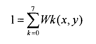
 ここに、重みWは、次の数式2に示すように正規化されている。
[数2]
 信号処理部35は、このような演算を全てのラスタアドレス(x,y)=(0,0)~(p,q)に対して行うことにより、1フレームの画像を構成する。こうして構成された画像は、内視鏡プロセッサ3に接続された図示しないモニタに表示され、あるいは内視鏡プロセッサ3に接続された図示しない記録装置に記録される。
続いて、信号処理部35は、ステップS1で開始した補正済変換テーブルの読み込みが終了したか否かを判定する(ステップS4)。そして、まだ終了していない場合には、補正済変換テーブルの読み込みを継続しながら、上述したステップS2へ戻って次のフレームに係るスパイラルデータの読み込みを行う。
一方、ステップS4において、補正済変換テーブルの読み込みが終了したと判定された場合には、理想変換テーブルを用いてマッピングを行っていた第1期間を終了して、補正済変換テーブルを用いてマッピングを行う第2期間に入る。
すなわちまず、ステップS2と同様に、スパイラルデータの読み込みを行う(ステップS5)。
次に、信号処理部35は、読み込みを終えて例えばプロセッサメモリ31に保持されている補正済変換テーブルを参照して、スパイラルデータをマッピングし、ラスタデータを生成する(ステップS6)。
このステップS6における処理は、理想変換テーブルに代えて補正済変換テーブルを用いる点を除いて、上述したステップS3の処理と同様である。
すなわち、信号処理部35は、スパイラルアドレスnのスパイラルデータが得られる毎に、図9の分配テーブルにおけるスパイラルアドレスnの欄を参照して分配先ラスタアドレス0~rを取得し、図10の合成テーブルにおける分配先ラスタアドレス0~rに対応する要素の「分配されたデータ」欄に、スパイラルアドレスnのスパイラルデータをコピーすることを、1フレーム分のスパイラルデータn=0~mの全てについて行う。
次に、信号処理部35は、合成テーブルに基づいて検出信号を重み付き線形結合することにより第2画素信号を算出する。すなわち、信号処理部35は、上述した数式1と同様にして、ラスタアドレス(x,y)に格納される第2画素信号であるラスタデータD’(x,y)を、次の数式3に示すように算出することを、全てのラスタアドレス(x,y)に対して行うことにより、1フレームの画像を構成する。
[数3]
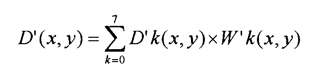 なお、重みW’が次の数式4に示すように正規化されているのも、理想変換テーブルの場合と同様である。
[数4]
 こうして構成された画像は、ステップS3と同様に、図示しないモニタに表示され、あるいは図示しない記録装置に記録される。
その後、撮影を終了するか否かを判定して(ステップS7)、終了しない場合には上述したステップS5へ戻って次のフレームに係るスパイラルデータの読み込みを行う。
一方、撮影を終了すると判定した場合には、補正済変換テーブルを用いてマッピングを行う第2期間が終了となって、この処理が終了される。
このような実施形態1によれば、第1期間において、入力部32から第2マッピングテーブル(補正済変換テーブル)の入力を開始すると共に、プロセッサメモリ31に保持されている第1マッピングテーブル(理想変換テーブル)および第1期間において得られた検出信号に基づいて、第1アドレス(ラスタアドレス)に格納される第1画素信号(ラスタデータ)を生成するようにしたために、第2マッピングテーブル(補正済変換テーブル)の読み込みが終了するのを待つことなく、電源投入後の短時間の内に起動が行われて画像を表示することが可能となる。
また、第2マッピングテーブル(補正済変換テーブル)の入力が完了した後の第2期間において、第2マッピングテーブル(補正済変換テーブル)および第2期間において得られた検出信号に基づいて、第2アドレス(ラスタアドレス)に格納される第2画素信号(ラスタデータ)を生成するようにしたために、第2期間において、より正確な画像を表示することが可能となる。
こうして、正確な画像表示を可能としながら、電源をオンしてから画像を表示できるまでの起動時間の短縮を図ることができる。補正済変換テーブルは、上述したようにデータ量が大きくスコープメモリ21から読み込むのに時間を要するために、起動後すぐに画像を得られるという顕著な効果を奏することができる。
特に、本実施形態においては、第2マッピングテーブル(補正済変換テーブル)が、第2軌道アドレス(スパイラルアドレス)と検出信号が分配される複数の第2アドレス(ラスタアドレス)との対応関係を表す分配テーブル(図9参照)と、第2アドレスと第2アドレスに分配された検出信号の重みとの対応関係を表す合成テーブル(図10参照)と、を含み、例えば後述する実施形態2で説明するような補正済変換テーブルに比してデータ量がより一層大きい。従って、スコープメモリ21から読み込むのにより長い時間を要するために、第1期間において第1マッピングテーブル(理想変換テーブル)を用いる構成を採用することで、より高い効果を奏することができる。
また、信号処理部35は、分配テーブルに基づいて検出信号を分配し、合成テーブルに基づいて検出信号を重み付き線形結合することにより第2画素信号(ラスタデータ)を算出しているために、テーブル参照と、乗算および加算という簡単な演算と、に基づき処理を行うことができ、小さい処理負荷で画像を高速に得ることができる。
そして、内視鏡2が照射光スポットにより走査を行って被写体からの戻り光を受光し、入力部32が内視鏡2に設けられたスコープメモリ21から第2マッピングテーブル(補正済変換テーブル)を入力するようにしたために、内視鏡システム1において、正確な内視鏡画像表示を可能としながら、起動時間の短縮を図ることができる。
また、内視鏡2に設けられたスコープメモリ21が第2マッピングテーブルを記憶しており、内視鏡プロセッサ3に内視鏡2が接続されることで第2マッピングテーブルの入力が行われるために、内視鏡2と第2マッピングテーブルとの組み合わせを確実なものとすることができる。
[実施形態2]
図11および図12は本発明の実施形態2を示したものであり、図11は理想変換テーブルの一例を示す図、図12は補正済変換テーブルの一例を示す図である。
図11および図12は本発明の実施形態2を示したものであり、図11は理想変換テーブルの一例を示す図、図12は補正済変換テーブルの一例を示す図である。
この実施形態2において、上述の実施形態1と同様である部分については同一の符号を付すなどして説明を適宜省略し、主として異なる点についてのみ説明する。
上述した実施形態1では、図5および図6を参照して説明したように、1つのスパイラルデータが複数のラスタアドレス(x,y)に分配され、逆に、1つのラスタデータは複数のスパイラルデータから構成されるようにしていた。これに対して、この実施形態2においては、1つのスパイラルアドレスnが1つのラスタアドレス(x,y)のみに対応する簡略化を行って、マッピング用の変換テーブルを作成したものとなっている。
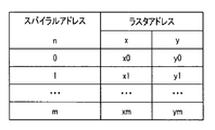
すなわち、図11に示す理想変換テーブルおよび図12に示す補正済変換テーブルは、何れも、スパイラルアドレスnとラスタアドレス(x,y)との対応関係を示すテーブルとなっており、相違点は、スパイラルアドレスnに対応するラスタアドレス(x,y)の中身、つまりラスタアドレス(x,y)に格納されているアドレス値となっている。一例を挙げれば、スパイラルアドレスn=0に対応して、図11に示す理想変換テーブルではラスタアドレス(x,y)=(x0,y0)が格納されており、図12に示す補正済変換テーブルではラスタアドレス(x,y)=(x’0,y’0)が格納されている等である。
すなわち、第1マッピングテーブル(理想変換テーブル)は、図11に示すように、第1軌道アドレス(スパイラルアドレスn)と第1アドレス(ラスタアドレス(x,y))との1対1の対応関係を表すテーブルである。
従って、信号処理部35は、第1軌道アドレス(スパイラルアドレス)に関連付けて得られた検出信号を、第1軌道アドレス(スパイラルアドレス)に対応する第1アドレス(ラスタアドレス)の第1画素信号(ラスタデータ)として設定する。
また、第2マッピングテーブル(補正済変換テーブル)は、図12に示すように、第2軌道アドレス(スパイラルアドレスn)と第2アドレス(ラスタアドレス(x,y))との1対1の対応関係を表すテーブルである。
この場合に、信号処理部35は、第2軌道アドレス(スパイラルアドレス)に関連付けて得られた検出信号を、第2軌道アドレス(スパイラルアドレス)に対応する第2アドレス(ラスタアドレス)の第2画素信号(ラスタデータ)として設定する。
従って、本実施形態では、検出信号を重み付き線形結合する処理が不要となり、理想変換テーブルと補正済変換テーブルとの何れにも、重みを与える欄は不要となる。
ただし、スパイラルデータを、スパイラルアドレスnに1対1に対応するラスタアドレス(x,y)に配置する方法では、スパイラルアドレスnと対応付けがないラスタアドレス(x,y)にはスパイラルデータが配置されないことになる。
そこで、信号処理部35は、第1画素信号(ラスタデータ)が格納されない第1アドレス(ラスタアドレス)がある場合には、その第1アドレス(ラスタアドレス)の周囲のアドレス(ラスタアドレス)に格納された第1画素信号(ラスタデータ)を用いて補間信号を算出し、補間信号を第1アドレス(ラスタアドレス)に格納する処理を行う。
同様に、信号処理部35は、第2画素信号(ラスタデータ)が格納されない第2アドレス(ラスタアドレス)がある場合には、第2アドレス(ラスタアドレス)の周囲のアドレス(ラスタアドレス)に格納された第2画素信号(ラスタデータ)を用いて補間信号を算出し、補間信号を第2アドレス(ラスタアドレス)に格納する処理を行う。
このような補間処理を行うことにより、全てのラスタアドレス(x,y)の信号値(信号値が0である場合も含む)が定められた画像が構成される。
ただし、補間処理は必須ではない。例えば、補間処理を行うのに代えて、信号が配置されていないラスタアドレス(x,y)に対して、例えば信号値0を与える処理を行うようにしても構わない。
このような実施形態2によれば、第1マッピングテーブル(理想変換テーブル)を、第1軌道アドレス(スパイラルアドレス)と第1アドレス(ラスタアドレス)との1対1の対応関係を表すテーブルとして、信号処理部35が、第1軌道アドレス(スパイラルアドレス)に関連付けて得られた検出信号を、第1軌道アドレス(スパイラルアドレス)に対応する第1アドレス(ラスタアドレス)の第1画素信号(ラスタデータ)として設定するために、検出信号を重み付き線形結合する処理が不要となり、電源がオンされた後に最初の1フレーム目の画像を表示可能になるまでの起動時タイムラグを上述した実施形態1よりも短縮することが可能となる。また、各フレームにおいて、走査を行ってからフレーム画像が表示可能になるまでのタイムラグも、上述した実施形態1より短縮することが可能となる。
同様に、第2マッピングテーブル(補正済変換テーブル)を、第2軌道アドレス(スパイラルアドレス)と第2アドレス(ラスタアドレス)との1対1の対応関係を表すテーブルとして、信号処理部35が、第2軌道アドレス(スパイラルアドレス)に関連付けて得られた検出信号を、第2軌道アドレス(スパイラルアドレス)に対応する第2アドレス(ラスタアドレス)の第2画素信号(ラスタデータ)として設定するために、検出信号を重み付き線形結合する処理が不要となり、第2期間においても、走査を行ってからフレーム画像が表示可能になるまでのタイムラグを、上述した実施形態1よりも短縮することが可能となる。
そして、第2マッピングテーブル(補正済変換テーブル)を、第2軌道アドレス(スパイラルアドレス)と第2アドレス(ラスタアドレス)との1対1の対応関係を表すテーブルとしたことで、補正済変換テーブルのデータ量を上述した実施形態1の補正済変換テーブルよりも小さくすることができ、第2期間に移行するまでの時間を短縮することができる。従って、正確な画像をより早く観察することが可能となる。また、スコープメモリ21に必要な記憶容量も削減することができる。
さらに、第1画素信号(ラスタデータ)が格納されない第1アドレス(ラスタアドレス)がある場合には、第1アドレス(ラスタアドレス)の周囲のアドレス(ラスタアドレス)に格納された第1画素信号(ラスタデータ)を用いて信号処理部35が補間信号を算出し、補間信号を第1アドレス(ラスタアドレス)に格納するようにしたために、信号値の変化が滑らかとなり、見た目がより自然な画像を構成することができる。
[実施形態3]
上記各図面を適宜参照して、本発明の実施形態3について説明する。この実施形態3において、上述の実施形態1,2と同様である部分については説明を適宜省略し、主として異なる点についてのみ説明する。
上記各図面を適宜参照して、本発明の実施形態3について説明する。この実施形態3において、上述の実施形態1,2と同様である部分については説明を適宜省略し、主として異なる点についてのみ説明する。
本実施形態は、上述した実施形態1と実施形態2の中間的な実施形態となっている。
すなわち、本実施形態は、理想変換テーブルとして、上述した実施形態2の例えば図11に示したような変換テーブルを用い、補正済変換テーブルとして、上述した実施形態1の例えば図9および図10に示したようなテーブルセットを用いるようになっている。
このような実施形態3によれば、電源がオンされた後に最初の1フレーム目の画像を表示可能になるまでの起動時タイムラグ、および第1期間において走査を行ってからフレーム画像が表示可能になるまでのタイムラグを上述した実施形態2と同様に短縮することが可能となるとともに、第2期間において上述した実施形態1と同様の正確な画像を得ることが可能となる。
[実施形態4]
図13は本発明の実施形態4を示したものであり、RAWデータの一例を示す図である。
図13は本発明の実施形態4を示したものであり、RAWデータの一例を示す図である。
この実施形態4において、上述の実施形態1~3と同様である部分については同一の符号を付すなどして説明を適宜省略し、主として異なる点についてのみ説明する。
本実施形態は、内視鏡プロセッサ3が、表示用のラスタデータに変換される前のスパイラルデータを、RAWデータとして出力することができるようにしたものとなっている。
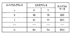
このRAWデータは、例えば図13に示すような構成のデータとなっている。
すなわち、スパイラルアドレスn=0~mに1対1に対応するように、スパイラルアドレスnに関連付けられた検出信号であるスパイラルデータD(n)=D(0)~D(m)が格納されている。さらに、スパイラルアドレスn=0~mに1対1に対応して、2次元座標のアドレスであるラスタアドレス(X,Y)が格納されている。
ここに、上述した実施形態のラスタアドレス(x,y)は、画像を構成する画素を基本としたアドレス(例えば、x方向の画素ピッチおよびy方向の画素ピッチを単位としたアドレス)である。これに対して、RAWデータに格納するラスタアドレス(X,Y)は、スパイラルアドレスnを2次元座標上で表現したアドレスであり、例えば内視鏡2の個体毎に測定器等を用いて精密に測定されたものである。従って、ラスタアドレス(x,y)は例えば整数値が格納されるアドレスであるのに対して、ラスタアドレス(X,Y)は一般に実数値が格納されるアドレスとなる。ただし、実用的には、測定器の測定精度等に応じた有効桁数のある小数(小数点を挟んだ整数部と小数部とで構成される数)などがラスタアドレス(X,Y)に格納される。
このRAWデータは、内視鏡プロセッサ3から出力されて、例えば記録装置に記録される。これにより、所望の時点で、記録装置から別途の画像処理装置にRAWデータを読み込んで画像処理を行うことで、表示画像を構成することができる。
例えば、画像を表示するモニタ等には、様々な画素構成のモニタが存在する。これに対して、RAWデータにはスパイラルアドレスnとラスタアドレス(Xn,Yn)との関係が記録されているために、任意のモニタに対して、スパイラルデータD(n)をどの表示画素(1つもしくは複数の表示画素)に分配するかを算出することができる。このときに、ラスタアドレス(Xn,Yn)は例えば実数で記載される精密なアドレスであるために、スパイラルアドレスnがどの表示画素に対応するかの位置関係を正確に算出して、正確な重み付けを行うことも可能となる。
このような実施形態4によれば、上述した実施形態1~3とほぼ同様の効果を奏するとともに、内視鏡プロセッサ3がRAWデータを出力するようにしたために、所望の時点で、別途の画像処理装置により画像処理を行うことが可能となる。これにより、特定の表示装置に依存することなく、任意の表示装置における精密な画像表示を行うことが可能となる。
[実施形態5]
上記各図面を適宜参照して、本発明の実施形態5について説明する。この実施形態5において、上述の実施形態1~4と同様である部分については説明を適宜省略し、主として異なる点についてのみ説明する。
上記各図面を適宜参照して、本発明の実施形態5について説明する。この実施形態5において、上述の実施形態1~4と同様である部分については説明を適宜省略し、主として異なる点についてのみ説明する。
上述した各実施形態においては、理想変換テーブルを使用してマッピングを行う第1期間が終了すると、補正済変換テーブルを使用してマッピングを行う第2期間に入っていた。
しかし、このような処理を行うと、第1期間における最後のフレーム画像と、第2期間における最初のフレーム画像とには、大きな変化が生じることになり、ユーザが違和感を覚えることとなる。
そこで、本実施形態は、第2マッピングテーブル(補正済変換テーブル)の入力が完了して第1期間が終了してから、第2期間が開始されるまでの間に、移行期間を設けたものとなっている。そして、この移行期間においては、例えば、第1期間において構成される画像と、第2期間において構成される画像と、の中間的な画像を構成する。
このために、信号処理部35は、移行期間において画像合成処理を行い、第1画素信号(ラスタデータ)と、第2画素信号(ラスタデータ)と、の両方を含む画像を生成するようになっている。
このときに画像合成のために用いる第1画素信号および第2画素信号の出所としては、例えば次のようなものがある。
第1の例においては、第1マッピングテーブル(理想変換テーブル)を用いてマッピングを行い画像を取得する第1期間と、入力が完了した第2マッピングテーブル(補正済変換テーブル)を用いてマッピングを行い画像を取得する第2期間と、の間の移行期間において、第2期間と同様に第2マッピングテーブル(補正済変換テーブル)を用いてマッピングを行い画像を生成する。
そして、移行期間において、第1期間の最後のフレームで得られた画像を構成する第1画素信号と、補正済変換テーブルを用いて得られた最新フレームの画像を構成する第2画像信号とを用いて画像合成処理を行い、第1画素信号と第2画素信号との両方を含む画像を生成するものである。
この第1の例によれば、第1画素信号と第2画素信号との両方を用いる移行期間であっても、マッピングを行って算出するのは第2画素信号だけで良く、第1画素信号を新たに算出する必要がないために、処理負荷の増大を避けることができる。
次に、第2の例においては、第1期間が終了した後の移行期間に、第1マッピングテーブル(理想変換テーブル)を用いてスパイラルデータをマッピングすることで第1画像信号を生成することと、入力が完了した第2マッピングテーブル(補正済変換テーブル)を用いてスパイラルデータをマッピングすることで第2画像信号を生成することと、の両方を、フレーム毎に行う。
そして、同一フレームのスパイラルデータに基づき生成された第1画素信号および第2画素信号を用いて画像合成処理を行い、第1画素信号と第2画素信号との両方を含む画像を生成するものである。
この第2の例によれば、各フレーム画像を生成する際に、2種類の変換テーブルを用いてマッピングを行う必要があるために処理負荷が増大するが、画像合成処理に用いる第1画素信号と第2画素信号とは同一取得時点の検出信号に基づき生成されているために、上述した第1の例のような異なる取得時点の検出信号に基づき生成された第1画素信号および第2画素信号を用いる場合の不整合が生じない利点がある。
さらに、第3の例においては、第1期間が終了した後の移行期間に、第1マッピングテーブル(理想変換テーブル)を用いてスパイラルデータをマッピングすることで第1画像信号を生成することと、入力が完了した第2マッピングテーブル(補正済変換テーブル)を用いてスパイラルデータをマッピングすることで第2画像信号を生成することとを、例えば1フレーム毎に交互に行う。
そして、最新のフレームと最新の1つ前のフレームとの内の、一方のフレームに係る第1画素信号と、他方のフレームに係る第2画素信号とを用いて画像合成処理を行い、第1画素信号と第2画素信号との両方を含む画像を生成するものである。
この第3の例によれば、1つのフレーム画像を生成する際に用いる変換テーブルは1種類であるために処理負荷の増大を避けることができると共に、画像合成処理に用いる第1画素信号と第2画素信号とは隣接するフレームに係るために、検出信号の取得時点の相違に起因する第1画素信号と第2画素信号との不整合を抑制することができる利点がある。
なお、第3の例の変形例としては、理想変換テーブルと補正済変換テーブルとを1フレーム毎に交互に行う(すなわち、1:1のフレーム割合で行う)のに代えて、m:nのフレーム割合で行い、移行期間中の、第1期間に近い時点では理想変換テーブルのフレーム割合を大きくし、第2期間に近い時点では補正済変換テーブルのフレーム割合を大きくするようにしても良い。
また、第1画素信号と第2画素信号とをどのような分布で組み合わせて画像合成処理するかの一例は、次のようになる。
例えば、走査軌道がスパイラル状をなす場合には、フレームが切り替わる毎に、例えば内周側からスパイラル状に第2画素信号の領域を大きくして、あるフレーム数になったときに全領域が第2画素信号で埋め尽くされるように画像を構成すると良い。
この方法によれば、走査軌道に準じた形で、第1画素信号の領域が第2画素信号の領域に次第に塗り替わる表示が行われる。
例えば、圧電素子に印加する電圧の周期を一定にして(ただし、振幅は変化させて)図3に示すようなスパイラル状の走査を行う場合、つまり内周側と外周側との何れであっても走査軌道が360度回転して進むのに要する時間が同一の場合であって、かつ、一定の時間間隔毎に検出信号を取得する場合には、取得されるスパイラルデータの密度は、中央部ほど高く、外周部へ行くほど低くなる。しかも、重要な被写体は画像の中央部に位置することが多い。こうした点からも、内周側が先に第2画素信号の領域に塗り替わる処理を行うことが好ましい。
ただし、第1画素信号の領域から第2画素信号の領域への塗り替えは、スパイラル状に行うに限るものではなく、中心部から外周部へ向けて円環状に順次行っても良いし、自動車のワイパーの動きに準じた方法で行っても良いし、その他、視覚的に違和感がない方法であれば、適宜の方法を採用して構わない。
このような実施形態5によれば、上述した実施形態1~4とほぼ同様の効果を奏するとともに、第1期間が終了してから第2期間が開始されるまでの間に移行期間を設けて、移行期間において理想変換テーブルに係る第1画素信号と補正済変換テーブルに係る第2画素信号との両方を含む画像を生成するようにしたために、第1期間から第2期間に切り替わるときの画像変化による違和感を軽減することが可能となる。
[実施形態6]
図14は本発明の実施形態6を示したものであり、変換テーブルの一例を示す図である。
図14は本発明の実施形態6を示したものであり、変換テーブルの一例を示す図である。
この実施形態6において、上述の実施形態1~5と同様である部分については同一の符号を付すなどして説明を適宜省略し、主として異なる点についてのみ説明する。
まず、図14に示す構造の変換テーブルは、理想変換テーブルと補正済変換テーブルとの何れに対しても適用することが可能である。そして、図14の変換テーブルは、上述した実施形態1の図7および図8に示した理想変換テーブル、あるいは図9および図10に示した補正済変換テーブルの何れとも、同じ変換結果を得ることができるテーブルとして構成されている。
スパイラルアドレスnと1つ以上のラスタアドレス(x,y)との対応を示す変換テーブルは、最も単純な構成として、例えば次のようなものが考えられる。
すなわち、表示画像として例えばフルHD画像を想定した場合に、画素構成は横1920画素×縦1080画素であり、総画素数は約2百万画素である。一方、スパイラルデータは走査方法によって取得されるデータ数が異なるが、フルHD画像として表示しようとするためにはフルHD画像の総画素数に近い数の検出信号が必要であり、例えば数十万のスパイラルデータが必要となる。従って、数十万×2百万の配列を構成して、配列内の必要箇所にスパイラルデータに乗算する重みを配置すれば、変換テーブルを構成することができる。
しかし、数十万×2百万の配列は非実用的なほど大きいだけでなく、スパイラルデータは、周囲の近い位置にあるラスタアドレスに分配されるだけであるので、配列内のほとんどの要素は値が0となり無駄である。
そこで、工夫したのが実施形態1の変換テーブルの構成である。実施形態1のm,p,qに対して上述したケースの数値を適用すると、m=数十万、p×q=2百万(p=1920,q=1080)となるが、例えばr=10の場合には、図7または図9に示した分配テーブルの配列は数十万×10=数百万、図8または図10に示した合成テーブルの配列は2百万×8=1600万となるために、2つのテーブルを合計した配列の要素数を2千万程度と見積もることができる。従って、数十万×2百万の配列に比べて、要素数を数万分の一にすることができ、テーブルをコンパクト化して、データ量を大幅に削減することができる。
しかも、実施形態1の変換テーブルの構成は、分配テーブルを参照すれば、スパイラルアドレスnに対応する分配先ラスタアドレスを直ちに取得することができ、合成テーブルにおける、取得した分配先ラスタアドレスの空き要素にスパイラルデータを配置していけば、ラスタデータを演算するのに必要なスパイラルデータと重みとの組み合わせが自動的に完成する。従って、得られた合成テーブルに基づいて検出信号を重み付き線形結合すれば求める画像を構成することができ、極めてシステマティックな優れた構成である。
ただし、実施形態1の変換テーブルは、複数のテーブル(分配テーブルおよび合成テーブル)により構成されていた。これに対して、本実施形態の変換テーブルは、1つのテーブルでマッピングを行うことができるように構成したものとなっている。
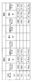
図14に示すように、本実施形態の変換テーブルは、ラスタアドレス(x,y)=(0,0)~(p,q)のそれぞれに対して、分配されるラスタデータの最大数(最大何個のラスタアドレスが対応するか)を示す要素の最大数が8(つまり、要素0~要素7)となるように設定されている(つまり、図8および図10に示した例と同様である)。ただし、要素の最大数が8に限定されるものではないことは、この図14に示す例においても同様である。
そして、あるラスタアドレス(x,y)のある要素kの欄には、対応するスパイラルアドレスnと重みW”とが記録されており、これらをそれぞれnk(x,y)、W”k(x,y)と記載することにする。
ここに、重みW”k(x,y)は、実施形態1の重みW,W’と同様に、ラスタアドレス(x,y)とスパイラルアドレスnk(x,y)との距離に基づいて定められたものであり、上述した数式2および数式4と同様に、次の数式5に示すように正規化されている。
[数5]
 そして、要素kの「分配されたデータ」欄には、スパイラルアドレスnk(x,y)において取得された検出信号であるスパイラルデータD”k(x,y)がコピーされるように構成されている。なお、上述したように、「分配されたデータ」欄のスパイラルデータD”k(x,y)は、撮影時に取得されるものであり、スコープメモリ21またはプロセッサメモリ31に不揮発に保持されるデータではない。
このような構成の変換テーブルの場合、スパイラルアドレスの要素数8と重みW”の要素数8とを合計すると16であるから、上述したケースに対応する要素数は、2百万×16~3千万程度であり、実施形態1とほぼ同様に、数十万×2百万の配列となる単純な変換テーブルに比べて、要素数を数万分の一にすることができ、テーブルをコンパクト化して、データ量を大幅に削減することができる。
そして、信号処理部35は、図14に示すような変換テーブルを用いて、図2に示したステップS3およびステップS6において、次のような処理を行う。
スパイラルデータは、上述したように、スパイラルアドレスn=0,1,2,…,mの順に、時系列に取得される。
信号処理部35は、あるスパイラルアドレスnのスパイラルデータが得られたら、図14の変換テーブルにおける全てのスパイラルアドレス欄から、対象となるスパイラルアドレスnに一致する項目を全て検索し、一致する各項目の「分配されたデータ」欄にスパイラルアドレスnのスパイラルデータをそれぞれコピーする。
このような処理を、スパイラルアドレスn=0からスパイラルアドレスn=mまで順次行うことで、図14の変換テーブルにおける「分配されたデータ」欄が埋められて、1フレーム分の検出信号が蓄積される。
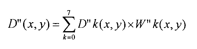
次に、信号処理部35は、変換テーブルに基づいて検出信号を重み付き線形結合することにより画素信号(第1画素信号または第2画素信号)を算出する。すなわち、ラスタアドレス(x,y)に格納される画素信号であるラスタデータD”(x,y)は、次の数式6に示すように、要素k=0~7に関する総和を求めることにより算出される。
[数6]
 信号処理部35は、このような演算を全てのラスタアドレス(x,y)=(0,0)~(p,q)に対して行うことにより、1フレームの画像を構成する。こうして構成された画像が、モニタに表示され、あるいは記録装置に記録されるのは、上述と同様である。
このような実施形態6によれば、図14に示すような1つのテーブルで構成される変換テーブルを用いるだけで、上述した実施形態1とほぼ同様の効果を奏することができる。
なお、上述した各実施形態においては、補正済変換テーブルが内視鏡2のスコープメモリ21に記憶されていて、内視鏡プロセッサ3の入力部32はスコープメモリ21から補正済変換テーブルを読み込んでいたが、これに限定されるものではない。例えば、院内ネットワークなどのネットワーク上の不揮発性メモリに内視鏡2個体毎の(定期的にキャリブレーションを行う場合には最新の)補正済変換テーブルを記憶しておき、内視鏡プロセッサ3に接続されている内視鏡2の機種および個体に応じて、内視鏡プロセッサ3の入力部32がネットワークから必要な補正済変換テーブルを読み込むという運用を行っても構わない。
そして、上述した各部は、回路として構成されていても良い。そして、任意の回路は、同一の機能を果たすことができれば、単一の回路として実装されていても良いし、複数の回路を組み合わせたものとして実装されていても構わない。さらに、任意の回路は、目的とする機能を果たすための専用回路として構成されるに限るものではなく、汎用回路に処理プログラムを実行させることで目的とする機能を果たす構成であっても構わない。
また、上述では主として内視鏡プロセッサおよび内視鏡システムについて説明したが、内視鏡プロセッサまたは内視鏡システムを上述したように作動させる作動方法であっても良いし、コンピュータに内視鏡プロセッサまたは内視鏡システムと同様の処理を行わせるための処理プログラム、該処理プログラムを記録するコンピュータにより読み取り可能な一時的でない記録媒体、等であっても構わない。
さらに、本発明は上述した実施形態そのままに限定されるものではなく、実施段階ではその要旨を逸脱しない範囲で構成要素を変形して具体化することができる。また、上記実施形態に開示されている複数の構成要素の適宜な組み合わせにより、種々の発明の態様を形成することができる。例えば、実施形態に示される全構成要素から幾つかの構成要素を削除しても良い。さらに、異なる実施形態にわたる構成要素を適宜組み合わせても良い。このように、発明の主旨を逸脱しない範囲内において種々の変形や応用が可能であることは勿論である。
本出願は、2016年2月8日に日本国に出願された特願2016-022011号を優先権主張の基礎として出願するものであり、上記の開示内容は、本願明細書、請求の範囲、図面に引用されたものとする。
Claims (6)
- 被写体を走査する照射光スポットの戻り光を所定のタイミングで受光して得られる検出信号の、前記走査を第1軌道で行った場合の第1軌道アドレスと、前記被写体上の位置を表す2次元座標の第1アドレスと、の対応関係を表す第1マッピングテーブルを保持するように構成されるプロセッサメモリと、
前記検出信号の、前記走査を第2軌道で行った場合の第2軌道アドレスと、前記被写体上の位置を表す2次元座標の第2アドレスと、の対応関係を表す第2マッピングテーブルが入力されるように構成される入力部と、
第1期間において、前記第2マッピングテーブルの入力を開始すると共に、前記第1マッピングテーブルおよび前記第1期間において得られた前記検出信号に基づいて、前記第1アドレスに格納される第1画素信号を生成し、前記第2マッピングテーブルの入力が完了した後の第2期間において、前記第2マッピングテーブルおよび前記第2期間において得られた前記検出信号に基づいて、前記第2アドレスに格納される第2画素信号を生成するように構成される信号処理部と、
を有することを特徴とする内視鏡プロセッサ。 - 前記第2マッピングテーブルは、前記第2軌道アドレスと前記検出信号が分配される複数の前記第2アドレスとの対応関係を表す分配テーブルと、前記第2アドレスと前記第2アドレスに分配された前記検出信号の重みとの対応関係を表す合成テーブルと、を含み、
前記信号処理部は、前記分配テーブルに基づいて前記検出信号を分配し、前記合成テーブルに基づいて前記検出信号を重み付き線形結合することにより前記第2画素信号を算出することを特徴とする請求項1に記載の内視鏡プロセッサ。 - 前記第1マッピングテーブルは、前記第1軌道アドレスと前記第1アドレスとの1対1の対応関係を表すテーブルであり、
前記信号処理部は、前記第1軌道アドレスに関連付けて得られた前記検出信号を、該第1軌道アドレスに対応する前記第1アドレスにおける前記第1画素信号として設定することを特徴とする請求項1に記載の内視鏡プロセッサ。 - 前記信号処理部は、前記第1画素信号が格納されない前記第1アドレスがある場合には、前記第1アドレスの周囲のアドレスに格納された前記第1画素信号を用いて補間信号を算出し、前記補間信号を前記第1アドレスに格納することを特徴とする請求項3に記載の内視鏡プロセッサ。
- 前記第2マッピングテーブルの入力が完了して前記第1期間が終了してから、前記第2期間が開始されるまでの間に移行期間があり、
前記信号処理部は、前記移行期間において、前記第1画素信号と、前記第2画素信号と、の両方を含む画像を生成することを特徴とする請求項1に記載の内視鏡プロセッサ。 - 請求項1に記載の内視鏡プロセッサと、
前記照射光スポットにより走査を行って、前記被写体からの前記戻り光を受光するように構成される内視鏡と、
前記内視鏡に設けられ、前記第2マッピングテーブルを記憶するように構成されるスコープメモリと、
を有し、
前記入力部は、前記スコープメモリから前記第2マッピングテーブルを入力することを特徴とする内視鏡システム。
Priority Applications (1)
| Application Number | Priority Date | Filing Date | Title |
|---|---|---|---|
| JP2017566519A JPWO2017138207A1 (ja) | 2016-02-08 | 2016-11-15 | 内視鏡プロセッサ、内視鏡システム |
Applications Claiming Priority (2)
| Application Number | Priority Date | Filing Date | Title |
|---|---|---|---|
| JP2016-022011 | 2016-02-08 | ||
| JP2016022011 | 2016-02-08 |
Publications (1)
| Publication Number | Publication Date |
|---|---|
| WO2017138207A1 true WO2017138207A1 (ja) | 2017-08-17 |
Family
ID=59563225
Family Applications (1)
| Application Number | Title | Priority Date | Filing Date |
|---|---|---|---|
| PCT/JP2016/083767 Ceased WO2017138207A1 (ja) | 2016-02-08 | 2016-11-15 | 内視鏡プロセッサ、内視鏡システム |
Country Status (2)
| Country | Link |
|---|---|
| JP (1) | JPWO2017138207A1 (ja) |
| WO (1) | WO2017138207A1 (ja) |
Cited By (2)
| Publication number | Priority date | Publication date | Assignee | Title |
|---|---|---|---|---|
| JP2025081394A (ja) * | 2020-01-28 | 2025-05-27 | ジャイラス エーシーエムアイ インク ディー/ビー/エー オリンパス サージカル テクノロジーズ アメリカ | 胆道診断デバイスを備えた医療デバイス |
| WO2025238686A1 (ja) * | 2024-05-13 | 2025-11-20 | オリンパスメディカルシステムズ株式会社 | 画像処理装置、画像処理システム、および、画像処理システムの作動方法 |
Citations (6)
| Publication number | Priority date | Publication date | Assignee | Title |
|---|---|---|---|---|
| JP2008514342A (ja) * | 2004-10-01 | 2008-05-08 | ユニバーシティ・オブ・ワシントン | イメージの歪みを減らす再マッピング法 |
| JP2011004929A (ja) * | 2009-06-25 | 2011-01-13 | Hoya Corp | 内視鏡装置 |
| JP2015020003A (ja) * | 2013-07-23 | 2015-02-02 | Hoya株式会社 | 画像歪み補正装置及び画像歪み補正方法 |
| JP2015206981A (ja) * | 2014-04-23 | 2015-11-19 | オリンパス株式会社 | 光走査型画像形成装置及び光走査型画像形成方法 |
| JP2016178965A (ja) * | 2015-03-23 | 2016-10-13 | オリンパス株式会社 | 走査型内視鏡システム |
| JP2017018421A (ja) * | 2015-07-13 | 2017-01-26 | オリンパス株式会社 | 内視鏡システム |
-
2016
- 2016-11-15 WO PCT/JP2016/083767 patent/WO2017138207A1/ja not_active Ceased
- 2016-11-15 JP JP2017566519A patent/JPWO2017138207A1/ja active Pending
Patent Citations (6)
| Publication number | Priority date | Publication date | Assignee | Title |
|---|---|---|---|---|
| JP2008514342A (ja) * | 2004-10-01 | 2008-05-08 | ユニバーシティ・オブ・ワシントン | イメージの歪みを減らす再マッピング法 |
| JP2011004929A (ja) * | 2009-06-25 | 2011-01-13 | Hoya Corp | 内視鏡装置 |
| JP2015020003A (ja) * | 2013-07-23 | 2015-02-02 | Hoya株式会社 | 画像歪み補正装置及び画像歪み補正方法 |
| JP2015206981A (ja) * | 2014-04-23 | 2015-11-19 | オリンパス株式会社 | 光走査型画像形成装置及び光走査型画像形成方法 |
| JP2016178965A (ja) * | 2015-03-23 | 2016-10-13 | オリンパス株式会社 | 走査型内視鏡システム |
| JP2017018421A (ja) * | 2015-07-13 | 2017-01-26 | オリンパス株式会社 | 内視鏡システム |
Cited By (2)
| Publication number | Priority date | Publication date | Assignee | Title |
|---|---|---|---|---|
| JP2025081394A (ja) * | 2020-01-28 | 2025-05-27 | ジャイラス エーシーエムアイ インク ディー/ビー/エー オリンパス サージカル テクノロジーズ アメリカ | 胆道診断デバイスを備えた医療デバイス |
| WO2025238686A1 (ja) * | 2024-05-13 | 2025-11-20 | オリンパスメディカルシステムズ株式会社 | 画像処理装置、画像処理システム、および、画像処理システムの作動方法 |
Also Published As
| Publication number | Publication date |
|---|---|
| JPWO2017138207A1 (ja) | 2018-12-06 |
Similar Documents
| Publication | Publication Date | Title |
|---|---|---|
| US20210285759A1 (en) | Laser enhanced reconstruction of 3d surface | |
| JP2013519417A5 (ja) | ||
| JP6794838B2 (ja) | 医用画像表示装置 | |
| US20190343479A1 (en) | X-ray diagnosis apparatus and x-ray diagnosis method | |
| JP2013531525A5 (ja) | ||
| JP5530577B1 (ja) | 走査型内視鏡システム | |
| JP7050131B2 (ja) | 眼の網膜の距離の幾何学的測定値を判定する方法、非一時的なコンピュータ可読な記憶媒体、及び眼の網膜の距離の幾何学的測定値を判定する画像システム | |
| JP6165591B2 (ja) | 画像処理装置、治療システム、及び画像処理方法 | |
| CN105208961A (zh) | 用于确定放置关节假体的位置的系统和方法 | |
| KR20180093939A (ko) | X-선 이미지를 보정하는 방법 | |
| JP2015181917A (ja) | 画像処理装置、治療システム及び画像処理方法 | |
| KR20180009707A (ko) | 화상처리장치, 화상처리방법 및 컴퓨터 판독 가능한 매체 | |
| WO2017138207A1 (ja) | 内視鏡プロセッサ、内視鏡システム | |
| JP2011139734A (ja) | 内視鏡装置 | |
| JP2011075336A (ja) | 3次元形状計測装置、3次元形状計測方法 | |
| KR101126891B1 (ko) | 슬라이스 영상을 제공하는 초음파 시스템 및 방법 | |
| US20100198564A1 (en) | Method for determining an arrangement of measurement points on an anatomical structure | |
| CN107485447B (zh) | 一种面向膝盖软骨移植术的术中器具位姿导航装置及方法 | |
| JP6580963B2 (ja) | 画像処理装置、画像処理方法およびx線診断装置 | |
| JP2016202251A (ja) | 放射線撮影システム、放射線撮影システムの制御方法およびプログラム | |
| JP6942622B2 (ja) | 光走査装置、カテーテル装置、及び距離計測装置 | |
| CN116612197A (zh) | 标定方法、装置、混合现实设备、系统、存储介质和产品 | |
| JP2020505999A (ja) | 膀胱マッピング | |
| CN116309752B (zh) | 用于影像配准的视角调整方法、装置、设备和介质 | |
| Al-Durgham et al. | Rigorous accuracy assessment for 3D reconstruction using time-series Dual Fluoroscopy (DF) image pairs |
Legal Events
| Date | Code | Title | Description |
|---|---|---|---|
| 121 | Ep: the epo has been informed by wipo that ep was designated in this application |
Ref document number: 16889908 Country of ref document: EP Kind code of ref document: A1 |
|
| ENP | Entry into the national phase |
Ref document number: 2017566519 Country of ref document: JP Kind code of ref document: A |
|
| NENP | Non-entry into the national phase |
Ref country code: DE |
|
| 122 | Ep: pct application non-entry in european phase |
Ref document number: 16889908 Country of ref document: EP Kind code of ref document: A1 |