WO2017135124A1 - Laminated sheet and packaging container sleeve - Google Patents
Laminated sheet and packaging container sleeve Download PDFInfo
- Publication number
- WO2017135124A1 WO2017135124A1 PCT/JP2017/002555 JP2017002555W WO2017135124A1 WO 2017135124 A1 WO2017135124 A1 WO 2017135124A1 JP 2017002555 W JP2017002555 W JP 2017002555W WO 2017135124 A1 WO2017135124 A1 WO 2017135124A1
- Authority
- WO
- WIPO (PCT)
- Prior art keywords
- layer
- laminated sheet
- vapor deposition
- film
- paper
- Prior art date
Links
Images


Classifications
-
- B—PERFORMING OPERATIONS; TRANSPORTING
- B32—LAYERED PRODUCTS
- B32B—LAYERED PRODUCTS, i.e. PRODUCTS BUILT-UP OF STRATA OF FLAT OR NON-FLAT, e.g. CELLULAR OR HONEYCOMB, FORM
- B32B15/00—Layered products comprising a layer of metal
- B32B15/04—Layered products comprising a layer of metal comprising metal as the main or only constituent of a layer, which is next to another layer of the same or of a different material
- B32B15/12—Layered products comprising a layer of metal comprising metal as the main or only constituent of a layer, which is next to another layer of the same or of a different material of paper or cardboard
-
- B—PERFORMING OPERATIONS; TRANSPORTING
- B32—LAYERED PRODUCTS
- B32B—LAYERED PRODUCTS, i.e. PRODUCTS BUILT-UP OF STRATA OF FLAT OR NON-FLAT, e.g. CELLULAR OR HONEYCOMB, FORM
- B32B3/00—Layered products comprising a layer with external or internal discontinuities or unevennesses, or a layer of non-planar form; Layered products having particular features of form
- B32B3/26—Layered products comprising a layer with external or internal discontinuities or unevennesses, or a layer of non-planar form; Layered products having particular features of form characterised by a particular shape of the outline of the cross-section of a continuous layer; characterised by a layer with cavities or internal voids ; characterised by an apertured layer
- B32B3/266—Layered products comprising a layer with external or internal discontinuities or unevennesses, or a layer of non-planar form; Layered products having particular features of form characterised by a particular shape of the outline of the cross-section of a continuous layer; characterised by a layer with cavities or internal voids ; characterised by an apertured layer characterised by an apertured layer, the apertures going through the whole thickness of the layer, e.g. expanded metal, perforated layer, slit layer regular cells B32B3/12
-
- B—PERFORMING OPERATIONS; TRANSPORTING
- B32—LAYERED PRODUCTS
- B32B—LAYERED PRODUCTS, i.e. PRODUCTS BUILT-UP OF STRATA OF FLAT OR NON-FLAT, e.g. CELLULAR OR HONEYCOMB, FORM
- B32B15/00—Layered products comprising a layer of metal
- B32B15/04—Layered products comprising a layer of metal comprising metal as the main or only constituent of a layer, which is next to another layer of the same or of a different material
- B32B15/08—Layered products comprising a layer of metal comprising metal as the main or only constituent of a layer, which is next to another layer of the same or of a different material of synthetic resin
- B32B15/082—Layered products comprising a layer of metal comprising metal as the main or only constituent of a layer, which is next to another layer of the same or of a different material of synthetic resin comprising vinyl resins; comprising acrylic resins
-
- B—PERFORMING OPERATIONS; TRANSPORTING
- B32—LAYERED PRODUCTS
- B32B—LAYERED PRODUCTS, i.e. PRODUCTS BUILT-UP OF STRATA OF FLAT OR NON-FLAT, e.g. CELLULAR OR HONEYCOMB, FORM
- B32B15/00—Layered products comprising a layer of metal
- B32B15/04—Layered products comprising a layer of metal comprising metal as the main or only constituent of a layer, which is next to another layer of the same or of a different material
- B32B15/08—Layered products comprising a layer of metal comprising metal as the main or only constituent of a layer, which is next to another layer of the same or of a different material of synthetic resin
- B32B15/085—Layered products comprising a layer of metal comprising metal as the main or only constituent of a layer, which is next to another layer of the same or of a different material of synthetic resin comprising polyolefins
-
- B—PERFORMING OPERATIONS; TRANSPORTING
- B32—LAYERED PRODUCTS
- B32B—LAYERED PRODUCTS, i.e. PRODUCTS BUILT-UP OF STRATA OF FLAT OR NON-FLAT, e.g. CELLULAR OR HONEYCOMB, FORM
- B32B15/00—Layered products comprising a layer of metal
- B32B15/04—Layered products comprising a layer of metal comprising metal as the main or only constituent of a layer, which is next to another layer of the same or of a different material
- B32B15/08—Layered products comprising a layer of metal comprising metal as the main or only constituent of a layer, which is next to another layer of the same or of a different material of synthetic resin
- B32B15/09—Layered products comprising a layer of metal comprising metal as the main or only constituent of a layer, which is next to another layer of the same or of a different material of synthetic resin comprising polyesters
-
- B—PERFORMING OPERATIONS; TRANSPORTING
- B32—LAYERED PRODUCTS
- B32B—LAYERED PRODUCTS, i.e. PRODUCTS BUILT-UP OF STRATA OF FLAT OR NON-FLAT, e.g. CELLULAR OR HONEYCOMB, FORM
- B32B15/00—Layered products comprising a layer of metal
- B32B15/20—Layered products comprising a layer of metal comprising aluminium or copper
-
- B—PERFORMING OPERATIONS; TRANSPORTING
- B32—LAYERED PRODUCTS
- B32B—LAYERED PRODUCTS, i.e. PRODUCTS BUILT-UP OF STRATA OF FLAT OR NON-FLAT, e.g. CELLULAR OR HONEYCOMB, FORM
- B32B27/00—Layered products comprising a layer of synthetic resin
- B32B27/06—Layered products comprising a layer of synthetic resin as the main or only constituent of a layer, which is next to another layer of the same or of a different material
- B32B27/08—Layered products comprising a layer of synthetic resin as the main or only constituent of a layer, which is next to another layer of the same or of a different material of synthetic resin
-
- B—PERFORMING OPERATIONS; TRANSPORTING
- B32—LAYERED PRODUCTS
- B32B—LAYERED PRODUCTS, i.e. PRODUCTS BUILT-UP OF STRATA OF FLAT OR NON-FLAT, e.g. CELLULAR OR HONEYCOMB, FORM
- B32B27/00—Layered products comprising a layer of synthetic resin
- B32B27/06—Layered products comprising a layer of synthetic resin as the main or only constituent of a layer, which is next to another layer of the same or of a different material
- B32B27/10—Layered products comprising a layer of synthetic resin as the main or only constituent of a layer, which is next to another layer of the same or of a different material of paper or cardboard
-
- B—PERFORMING OPERATIONS; TRANSPORTING
- B32—LAYERED PRODUCTS
- B32B—LAYERED PRODUCTS, i.e. PRODUCTS BUILT-UP OF STRATA OF FLAT OR NON-FLAT, e.g. CELLULAR OR HONEYCOMB, FORM
- B32B27/00—Layered products comprising a layer of synthetic resin
- B32B27/30—Layered products comprising a layer of synthetic resin comprising vinyl (co)polymers; comprising acrylic (co)polymers
- B32B27/304—Layered products comprising a layer of synthetic resin comprising vinyl (co)polymers; comprising acrylic (co)polymers comprising vinyl halide (co)polymers, e.g. PVC, PVDC, PVF, PVDF
-
- B—PERFORMING OPERATIONS; TRANSPORTING
- B32—LAYERED PRODUCTS
- B32B—LAYERED PRODUCTS, i.e. PRODUCTS BUILT-UP OF STRATA OF FLAT OR NON-FLAT, e.g. CELLULAR OR HONEYCOMB, FORM
- B32B27/00—Layered products comprising a layer of synthetic resin
- B32B27/30—Layered products comprising a layer of synthetic resin comprising vinyl (co)polymers; comprising acrylic (co)polymers
- B32B27/306—Layered products comprising a layer of synthetic resin comprising vinyl (co)polymers; comprising acrylic (co)polymers comprising vinyl acetate or vinyl alcohol (co)polymers
-
- B—PERFORMING OPERATIONS; TRANSPORTING
- B32—LAYERED PRODUCTS
- B32B—LAYERED PRODUCTS, i.e. PRODUCTS BUILT-UP OF STRATA OF FLAT OR NON-FLAT, e.g. CELLULAR OR HONEYCOMB, FORM
- B32B27/00—Layered products comprising a layer of synthetic resin
- B32B27/32—Layered products comprising a layer of synthetic resin comprising polyolefins
-
- B—PERFORMING OPERATIONS; TRANSPORTING
- B32—LAYERED PRODUCTS
- B32B—LAYERED PRODUCTS, i.e. PRODUCTS BUILT-UP OF STRATA OF FLAT OR NON-FLAT, e.g. CELLULAR OR HONEYCOMB, FORM
- B32B27/00—Layered products comprising a layer of synthetic resin
- B32B27/34—Layered products comprising a layer of synthetic resin comprising polyamides
-
- B—PERFORMING OPERATIONS; TRANSPORTING
- B32—LAYERED PRODUCTS
- B32B—LAYERED PRODUCTS, i.e. PRODUCTS BUILT-UP OF STRATA OF FLAT OR NON-FLAT, e.g. CELLULAR OR HONEYCOMB, FORM
- B32B27/00—Layered products comprising a layer of synthetic resin
- B32B27/36—Layered products comprising a layer of synthetic resin comprising polyesters
-
- B—PERFORMING OPERATIONS; TRANSPORTING
- B32—LAYERED PRODUCTS
- B32B—LAYERED PRODUCTS, i.e. PRODUCTS BUILT-UP OF STRATA OF FLAT OR NON-FLAT, e.g. CELLULAR OR HONEYCOMB, FORM
- B32B7/00—Layered products characterised by the relation between layers; Layered products characterised by the relative orientation of features between layers, or by the relative values of a measurable parameter between layers, i.e. products comprising layers having different physical, chemical or physicochemical properties; Layered products characterised by the interconnection of layers
- B32B7/04—Interconnection of layers
- B32B7/12—Interconnection of layers using interposed adhesives or interposed materials with bonding properties
-
- B—PERFORMING OPERATIONS; TRANSPORTING
- B65—CONVEYING; PACKING; STORING; HANDLING THIN OR FILAMENTARY MATERIAL
- B65D—CONTAINERS FOR STORAGE OR TRANSPORT OF ARTICLES OR MATERIALS, e.g. BAGS, BARRELS, BOTTLES, BOXES, CANS, CARTONS, CRATES, DRUMS, JARS, TANKS, HOPPERS, FORWARDING CONTAINERS; ACCESSORIES, CLOSURES, OR FITTINGS THEREFOR; PACKAGING ELEMENTS; PACKAGES
- B65D5/00—Rigid or semi-rigid containers of polygonal cross-section, e.g. boxes, cartons or trays, formed by folding or erecting one or more blanks made of paper
- B65D5/42—Details of containers or of foldable or erectable container blanks
-
- B—PERFORMING OPERATIONS; TRANSPORTING
- B65—CONVEYING; PACKING; STORING; HANDLING THIN OR FILAMENTARY MATERIAL
- B65D—CONTAINERS FOR STORAGE OR TRANSPORT OF ARTICLES OR MATERIALS, e.g. BAGS, BARRELS, BOTTLES, BOXES, CANS, CARTONS, CRATES, DRUMS, JARS, TANKS, HOPPERS, FORWARDING CONTAINERS; ACCESSORIES, CLOSURES, OR FITTINGS THEREFOR; PACKAGING ELEMENTS; PACKAGES
- B65D65/00—Wrappers or flexible covers; Packaging materials of special type or form
- B65D65/38—Packaging materials of special type or form
- B65D65/40—Applications of laminates for particular packaging purposes
-
- B—PERFORMING OPERATIONS; TRANSPORTING
- B32—LAYERED PRODUCTS
- B32B—LAYERED PRODUCTS, i.e. PRODUCTS BUILT-UP OF STRATA OF FLAT OR NON-FLAT, e.g. CELLULAR OR HONEYCOMB, FORM
- B32B2250/00—Layers arrangement
- B32B2250/05—5 or more layers
-
- B—PERFORMING OPERATIONS; TRANSPORTING
- B32—LAYERED PRODUCTS
- B32B—LAYERED PRODUCTS, i.e. PRODUCTS BUILT-UP OF STRATA OF FLAT OR NON-FLAT, e.g. CELLULAR OR HONEYCOMB, FORM
- B32B2250/00—Layers arrangement
- B32B2250/44—Number of layers variable across the laminate
-
- B—PERFORMING OPERATIONS; TRANSPORTING
- B32—LAYERED PRODUCTS
- B32B—LAYERED PRODUCTS, i.e. PRODUCTS BUILT-UP OF STRATA OF FLAT OR NON-FLAT, e.g. CELLULAR OR HONEYCOMB, FORM
- B32B2255/00—Coating on the layer surface
- B32B2255/10—Coating on the layer surface on synthetic resin layer or on natural or synthetic rubber layer
-
- B—PERFORMING OPERATIONS; TRANSPORTING
- B32—LAYERED PRODUCTS
- B32B—LAYERED PRODUCTS, i.e. PRODUCTS BUILT-UP OF STRATA OF FLAT OR NON-FLAT, e.g. CELLULAR OR HONEYCOMB, FORM
- B32B2255/00—Coating on the layer surface
- B32B2255/20—Inorganic coating
-
- B—PERFORMING OPERATIONS; TRANSPORTING
- B32—LAYERED PRODUCTS
- B32B—LAYERED PRODUCTS, i.e. PRODUCTS BUILT-UP OF STRATA OF FLAT OR NON-FLAT, e.g. CELLULAR OR HONEYCOMB, FORM
- B32B2255/00—Coating on the layer surface
- B32B2255/20—Inorganic coating
- B32B2255/205—Metallic coating
-
- B—PERFORMING OPERATIONS; TRANSPORTING
- B32—LAYERED PRODUCTS
- B32B—LAYERED PRODUCTS, i.e. PRODUCTS BUILT-UP OF STRATA OF FLAT OR NON-FLAT, e.g. CELLULAR OR HONEYCOMB, FORM
- B32B2255/00—Coating on the layer surface
- B32B2255/26—Polymeric coating
-
- B—PERFORMING OPERATIONS; TRANSPORTING
- B32—LAYERED PRODUCTS
- B32B—LAYERED PRODUCTS, i.e. PRODUCTS BUILT-UP OF STRATA OF FLAT OR NON-FLAT, e.g. CELLULAR OR HONEYCOMB, FORM
- B32B2255/00—Coating on the layer surface
- B32B2255/28—Multiple coating on one surface
-
- B—PERFORMING OPERATIONS; TRANSPORTING
- B32—LAYERED PRODUCTS
- B32B—LAYERED PRODUCTS, i.e. PRODUCTS BUILT-UP OF STRATA OF FLAT OR NON-FLAT, e.g. CELLULAR OR HONEYCOMB, FORM
- B32B2307/00—Properties of the layers or laminate
- B32B2307/40—Properties of the layers or laminate having particular optical properties
- B32B2307/406—Bright, glossy, shiny surface
-
- B—PERFORMING OPERATIONS; TRANSPORTING
- B32—LAYERED PRODUCTS
- B32B—LAYERED PRODUCTS, i.e. PRODUCTS BUILT-UP OF STRATA OF FLAT OR NON-FLAT, e.g. CELLULAR OR HONEYCOMB, FORM
- B32B2307/00—Properties of the layers or laminate
- B32B2307/40—Properties of the layers or laminate having particular optical properties
- B32B2307/412—Transparent
-
- B—PERFORMING OPERATIONS; TRANSPORTING
- B32—LAYERED PRODUCTS
- B32B—LAYERED PRODUCTS, i.e. PRODUCTS BUILT-UP OF STRATA OF FLAT OR NON-FLAT, e.g. CELLULAR OR HONEYCOMB, FORM
- B32B2307/00—Properties of the layers or laminate
- B32B2307/70—Other properties
- B32B2307/71—Resistive to light or to UV
-
- B—PERFORMING OPERATIONS; TRANSPORTING
- B32—LAYERED PRODUCTS
- B32B—LAYERED PRODUCTS, i.e. PRODUCTS BUILT-UP OF STRATA OF FLAT OR NON-FLAT, e.g. CELLULAR OR HONEYCOMB, FORM
- B32B2307/00—Properties of the layers or laminate
- B32B2307/70—Other properties
- B32B2307/718—Weight, e.g. weight per square meter
-
- B—PERFORMING OPERATIONS; TRANSPORTING
- B32—LAYERED PRODUCTS
- B32B—LAYERED PRODUCTS, i.e. PRODUCTS BUILT-UP OF STRATA OF FLAT OR NON-FLAT, e.g. CELLULAR OR HONEYCOMB, FORM
- B32B2307/00—Properties of the layers or laminate
- B32B2307/70—Other properties
- B32B2307/724—Permeability to gases, adsorption
- B32B2307/7242—Non-permeable
- B32B2307/7246—Water vapor barrier
-
- B—PERFORMING OPERATIONS; TRANSPORTING
- B32—LAYERED PRODUCTS
- B32B—LAYERED PRODUCTS, i.e. PRODUCTS BUILT-UP OF STRATA OF FLAT OR NON-FLAT, e.g. CELLULAR OR HONEYCOMB, FORM
- B32B2307/00—Properties of the layers or laminate
- B32B2307/70—Other properties
- B32B2307/732—Dimensional properties
-
- B—PERFORMING OPERATIONS; TRANSPORTING
- B32—LAYERED PRODUCTS
- B32B—LAYERED PRODUCTS, i.e. PRODUCTS BUILT-UP OF STRATA OF FLAT OR NON-FLAT, e.g. CELLULAR OR HONEYCOMB, FORM
- B32B2439/00—Containers; Receptacles
-
- B—PERFORMING OPERATIONS; TRANSPORTING
- B65—CONVEYING; PACKING; STORING; HANDLING THIN OR FILAMENTARY MATERIAL
- B65D—CONTAINERS FOR STORAGE OR TRANSPORT OF ARTICLES OR MATERIALS, e.g. BAGS, BARRELS, BOTTLES, BOXES, CANS, CARTONS, CRATES, DRUMS, JARS, TANKS, HOPPERS, FORWARDING CONTAINERS; ACCESSORIES, CLOSURES, OR FITTINGS THEREFOR; PACKAGING ELEMENTS; PACKAGES
- B65D2203/00—Decoration means, markings, information elements, contents indicators
-
- B—PERFORMING OPERATIONS; TRANSPORTING
- B65—CONVEYING; PACKING; STORING; HANDLING THIN OR FILAMENTARY MATERIAL
- B65D—CONTAINERS FOR STORAGE OR TRANSPORT OF ARTICLES OR MATERIALS, e.g. BAGS, BARRELS, BOTTLES, BOXES, CANS, CARTONS, CRATES, DRUMS, JARS, TANKS, HOPPERS, FORWARDING CONTAINERS; ACCESSORIES, CLOSURES, OR FITTINGS THEREFOR; PACKAGING ELEMENTS; PACKAGES
- B65D5/00—Rigid or semi-rigid containers of polygonal cross-section, e.g. boxes, cartons or trays, formed by folding or erecting one or more blanks made of paper
- B65D5/42—Details of containers or of foldable or erectable container blanks
- B65D5/72—Contents-dispensing means
- B65D5/74—Spouts
- B65D5/746—Spouts formed separately from the container
- B65D5/747—Spouts formed separately from the container with means for piercing or cutting the container wall or a membrane connected to said wall
- B65D5/748—Spouts formed separately from the container with means for piercing or cutting the container wall or a membrane connected to said wall a major part of the container wall or membrane being left inside the container after the opening
Definitions
- the present invention relates to a laminated sheet for a packaging container and a packaging container sleeve having a high metallic luster on the surface and excellent contents preservability.
- Paper containers excellent in the preservation of contents have been widely used. Paper containers are made from recyclable wood pulp, which can be recycled as papermaking raw materials even after use. For this reason, paper containers have been evaluated as containers with less burden on the global environment as compared with bottles, cans, plastic containers, etc., as awareness of global environment protection increases.
- the paper container has a drawback that it lacks a sense of quality in terms of design compared to bottles, cans, plastic containers and the like.
- Various paper containers having a metallic luster on the surface have been proposed as one means to compensate for this drawback.
- the paper container described in Patent Document 1 includes a gas barrier layer including a metal oxide vapor deposition layer and an inner layer film having a sealant layer, a paper base material, a thin paper having a light shielding layer on the back surface and a metal vapor deposition layer on the surface, Is a paper container made of a laminated sheet in which a thermoplastic resin layer is provided on the outermost layer.
- Patent Document 2 and Patent Document 3 are paper containers that exhibit a good metallic luster by using a metal-deposited film layer on the outside of the paper layer.
- JP 2010-52761 A Japanese Patent Laid-Open No. 11-334756 JP 2002-370307 A
- a gas barrier layer inside the paper layer.
- a layer having at least water vapor barrier properties is often used.
- the paper layer usually holds a small amount of moisture inside.
- the moisture inside the paper layer becomes water vapor.
- the generated water vapor escapes to the outside, so that no particular problem occurs.
- bubbling This phenomenon is called bubbling.
- bubbling occurs, not only the appearance of the paper container is remarkably impaired, but also the storage performance as a container is impaired.
- the problem to be solved by the present invention is to provide a laminated sheet and a packaging container sleeve for a packaging container that have a metallic luster with a high brightness on the surface and are less likely to cause bubbling in the production process.
- one aspect of the present invention is formed by folding and heat-sealing each region including each end of a cylindrical body formed by heat-sealing two side edges of a sheet material.
- a laminated sheet used in the manufacture of a packaging container having a top and a bottom, sandwiched between a top seal part that is an area corresponding to the top part, a bottom seal part that is an area corresponding to the bottom part, and a top seal part and a bottom seal part Including a side wall portion that is a region, and an inner layer film having a water vapor barrier layer and a sealant layer, a paper base material, and a thermoplastic resin layer in order from the inner side of the packaging container.
- a glossy layer is provided except for at least a part of the region included in the top seal portion or the bottom seal portion.
- the other situation of this invention is the packaging container sleeve which heat-sealed two side edges of this lamination sheet.
- the liquid paper container according to the present invention has a water vapor barrier layer on the inner surface side of the paper base material, and thus has excellent storage stability. Further, by providing a gloss layer on the outside of the paper substrate, a metallic luster with a high glitter feeling is exhibited. Further, by providing a part where the gloss layer does not exist in all or a part of the seal part, it is possible to prevent the occurrence of bubbling in the manufacturing process.
- FIG. 1 is a perspective view showing a liquid paper container according to an embodiment of the present invention.
- FIG. 2 is a plan view showing a laminated sheet according to an embodiment of the present invention.
- FIG. 3 is a plan view showing a laminated sheet according to an embodiment of the present invention.
- FIG. 4 is a plan view showing a laminated sheet according to an embodiment of the present invention.
- FIG. 5 is a plan view showing a laminated sheet according to an embodiment of the present invention.
- FIG. 6 is a cross-sectional explanatory view showing the A-A ′ cross section of FIG. 2 of the laminated sheet according to one embodiment of the present invention.
- FIG. 7 is a cross-sectional explanatory view of a laminated sheet according to an embodiment of the present invention.
- FIG. 1 is a perspective view showing a liquid paper container according to an embodiment of the present invention.
- FIG. 2 is a plan view showing a laminated sheet according to an embodiment of the present invention.
- FIG. 3 is
- FIG. 8 is a cross-sectional explanatory view showing the A-A ′ cross section of FIG. 2 of the laminated sheet according to one embodiment of the present invention.
- FIG. 9 is an explanatory cross-sectional view of a laminated sheet according to an embodiment of the present invention.
- FIG. 10 is a cross-sectional explanatory view of a laminated sheet according to an embodiment of the present invention.
- FIG. 11 is a cross-sectional explanatory view of a laminated sheet according to an embodiment of the present invention.
- FIG. 12 is a cross-sectional explanatory view of a laminated sheet according to an embodiment of the present invention.
- FIG. 13 is a cross-sectional explanatory view of a laminated sheet according to an embodiment of the present invention.
- FIG. 14 is an explanatory plan view showing a laminated sheet according to an embodiment of the present invention and a comparative example.
- FIG. 1 is a perspective view showing an embodiment of a liquid paper container 1 which is a packaging container according to the present embodiment.
- the shape of the liquid paper container 1 is a so-called gable top type paper container with a stopper having a gable roof shape at the top and a flat bottom surface.
- the shape of the packaging container of the present invention is not limited to this, and may be any shape such as a block shape, a cylindrical paper can shape, or a cup shape.
- FIG. 2 is an explanatory plan view showing one embodiment of the punched laminated sheet 2 constituting the liquid paper container 1.
- a hatched portion in FIG. 2 indicates a portion 5P where a gloss layer 5 described later is present.
- the laminated sheet 2 includes a top seal portion 20 t that forms the top of the gable roof type portion of the liquid paper container 1, a bottom seal portion 20 b that forms a flat bottom portion, and other portions. It has the side part 20 to form.
- the gloss layer 5 does not exist in the top seal portion 20t and the bottom seal portion 20b.
- the gloss layer 5 is present except for portions that overlap the top seal portion 20t and the bottom seal portion 20b.
- the side seal portion has only two laminated sheets when heat-sealed, and since the heating and pressing are simultaneously performed using a hot plate at the time of heat-sealing, a glossy layer with low water vapor permeability The bubbling phenomenon is not likely to occur even if there is.
- preheating is performed by blowing hot air
- heat sealing is performed by stacking a maximum of five laminated sheets.
- the bottom seal portion 20b as many as eight laminated sheets are stacked after preheating with hot air.
- water vapor permeates into the seal portion due to severe conditions such as temperature and time of preheating with hot air and not being pressed simultaneously with the preheating.
- the gloss layer 5 having a low property is present, a bubbling phenomenon is likely to occur. Even in the bottom seal portion where the number of laminated sheets is the largest, and thus bubbling is likely to occur, the bubbling prevention effect is exhibited by the absence of the glossy layer.
- the portion where the glossy layer 5 does not exist is a top seal as shown in FIG. Although it can also be set as the part 20t and the bottom seal part 20b, as shown in FIG. 3, it can also be set only as the bottom seal part 20b.
- the gloss layer 5 may be partially provided in the bottom seal portion 20b.
- the gloss layer 5 is provided in a range within a predetermined distance from the boundary side edge with the side surface portion 20 in the bottom seal portion 20 b, and is not provided in a range exceeding the predetermined distance. It may be.
- a portion of the bottom surface that is slightly visible when connected to the lower end of the body portion is glossy in the same manner as the body portion. An excellent design property can be imparted to the liquid paper container 1 without giving a good impression.
- the glossy layer 5 should not exist, for example, the shape and size of the paper container, the material and water vapor permeability of the glossy layer 5, the thickness and thermal conductivity of the laminated sheet, and the sealing conditions of each sealing part Determined by etc.
- the gloss layer 5 may not be provided only in a portion where the bubbling is most likely to occur among the heat-sealed portions.
- a method for preventing the glossy layer 5 from being provided in a predetermined portion of the laminated sheet 2 a method of narrowing the sheet width of the glossy layer 5 or a plurality of glossy layer sheets slit to a predetermined width in the bonding step. There are methods such as stacking sheets together.
- FIG. 6 is a cross-sectional explanatory view of the laminated sheet 2 and shows a cross section taken along the line A-A ′ in FIG. 2.
- the laminated sheet 2 is formed by laminating an inner layer film 12 having a water vapor barrier layer 10 and a sealant layer 11, a paper base material 8, and a gloss layer 5 with adhesive resins 7 and 9 in this embodiment.
- the gloss layer 5 is configured not to exist in a portion corresponding to the top seal portion 20t. Although not shown in FIG. 6, the gloss layer 5 does not exist even in the portion corresponding to the bottom seal portion 20b.
- a metal foil such as an aluminum foil, a metal vapor deposition film such as an aluminum vapor deposition film, or a sheet having a metallic luster such as a hologram foil or a glitter feeling based on light interference can be used.
- the printed pattern layer 3 is provided on the thermoplastic resin layer 4, but the printed pattern layer 3 may be provided below the thermoplastic resin layer 4.
- a paper pack base paper is generally used as the paper base 8, but a paper pack base paper of 100% virgin pulp having a basis weight of about 250 to 450 g / m 2 is preferable from the viewpoint of paper strength and hygiene.
- Cardboard that is normally used for paper boxes can also be used.
- Examples of the water vapor barrier layer 10 include aluminum foil, ethylene vinyl alcohol copolymer layer, polyvinylidene chloride film, polyvinylidene chloride coated film, nylon film, polyethylene terephthalate resin film, and inorganic substances such as silicon dioxide and aluminum oxide.
- a gas barrier film deposited on the surface of a resin (PET) film or the like is preferably used.
- the inorganic substance used for the gas barrier film is an oxide such as silicon, aluminum, magnesium, titanium, zirconium, or tin, and aluminum oxide, silicon oxide, magnesium oxide, or the like is particularly preferable.
- the water vapor barrier layer 10 When an aluminum foil is selected as the water vapor barrier layer 10, a sufficient light barrier property is obtained in addition to a sufficient gas barrier property, which is excellent in long-term storage. However, the entire container cannot be heated in the microwave.
- a polyolefin resin is generally used.
- low density polyethylene medium density polyethylene, linear low density polyethylene, ethylene / vinyl acetate copolymer, ethylene / ⁇ -olefin copolymer
- ethylene resins such as coalescence
- polypropylene resins such as homopolypropylene, propylene / ethylene random copolymer, propylene / ethylene block copolymer, and propylene / ⁇ -olefin copolymer are used.
- FIG. 7 is a cross-sectional explanatory view showing another embodiment of the laminated sheet 2.
- the gloss layer 5 is a vapor deposition film in which the vapor deposition layer 5a is provided on the vapor deposition substrate 5b, and the gloss layer 5 does not exist in all or part of the seal portion.
- a film for a vapor deposition substrate As a film for a vapor deposition substrate, a polyethylene terephthalate resin (PET) film, a polypropylene resin (PP) film, or the like is generally used. In the case of paper, thin paper provided with a vapor deposition anchor layer is used.
- PET polyethylene terephthalate resin
- PP polypropylene resin
- a PET film having a thickness of 4 ⁇ m to 25 ⁇ m and a PP film are most commonly used.
- the vapor deposition layer 5a formed on the surface is most commonly an aluminum vapor deposition layer, but is not particularly limited.
- an iris foil in which a plurality of metal oxide layers are formed, a hologram foil in which fine irregularities are formed on the surface, or the like may be used.
- a deposited anchor coat layer may be provided on the surface of the base film 5b.
- the metal glossiness of the vapor deposition layer is improved and the adhesion of the vapor deposition layer to the film is improved.
- the vapor deposition base material 5b is paper, although not specifically illustrated in the drawing, it is particularly preferable to provide a vapor deposition anchor coat layer.
- the vapor deposition layer 5a is formed on the upper surface of the vapor deposition substrate 5b, that is, the outer surface of the paper container, but when the vapor deposition substrate 5b is a transparent film, the vapor deposition layer You may form 5a in the lower surface of the vapor deposition base material 5b, ie, the inner surface of a paper container.
- FIG. 8 is a cross-sectional explanatory view showing another embodiment of the laminated sheet 2.
- the glossy layer 5 is a vapor deposition layer 5a formed on the surface of the vapor deposition substrate 5b.
- the vapor deposition substrate 5 b is present in the seal portion, but only the vapor deposition layer 5 a is not present as the glossy layer 5.
- the thickness of the vapor deposition layer 5a is extremely thin, such a structure reduces the thickness unevenness in the width direction of the laminated sheet 2 to a negligible level and facilitates the bonding process. .
- a mask plate is installed so that vapor deposition is not performed at a target place, or a predetermined portion of the vapor deposition layer once formed on the entire surface. There is a method of removing only the deposited layer.
- thermoplastic resin layer 4 is formed by extruding a thermoplastic resin such as polyethylene resin or polypropylene resin from the other extruder on the surface of the gloss layer 5 narrowed in advance.
- the thermoplastic resin layer 4 is wider than the width of the gloss layer 5.
- the printed pattern layer 3 is formed on the surface of the thermoplastic resin layer 4 while being aligned with the bonding position of the gloss layer 5.
- the adhesive resin layers 7 and 9 are extruded from another extruder, and the printed sheet including the glossy layer 5, the paper base material 8, and the previously created inner layer film 12 are bonded together.
- a so-called polysand resin can be used.
- EMAA ethylene-methacrylic acid copolymer
- EAA ethylene-acrylic acid copolymer
- Polyethylene resin is preferably used.
- the laminated body obtained as described above is punched into a predetermined blank shape to obtain a laminated sheet 2 as shown in FIG.
- the laminated sheet 2 is bent along a ruled line into a cylindrical shape, and both end edges (side seal part 20s and the opposite end edge) of the side face part 20 are overlapped, and the overlapped part is heat sealed using a hot plate, A packaging container sleeve is formed. Further, the top seal portion 20t and the bottom seal portion 20b of the packaging container sleeve are heated by blowing hot air, respectively, and the marginal portion which is the edge portion is overlapped and sealed, thereby forming the liquid paper container 1 as the packaging container. Is done.
- the water contained in the paper substrate 8 evaporates to become water vapor. Since the water vapor barrier layer 10 exists on the inner surface side of the paper container, water vapor generated from the paper base material cannot permeate.
- the outer surface side of the seal portion where the gloss layer 5 does not exist is easy to permeate water vapor, so that there is less risk of bubbling in this portion. Further, by providing a structure in which a sheet containing aluminum foil or a vapor deposition sheet is not provided in all or a part of the seal portion, these expensive sheets can be saved and the cost can be reduced.
- the gloss layer is a vapor deposition layer deposited on the vapor deposition base material and has a structure in which the vapor deposition layer does not exist in all or part of the seal portion, a normal bonding process can be used, Becomes easy.
- the shape of the packaging container according to this embodiment is the same as that of the first embodiment.
- FIG. 9 is a cross-sectional explanatory view of the laminated sheet 2 for a packaging container according to this embodiment.
- the laminated sheet 2 is formed by bonding an inner layer film 12 having a water vapor barrier layer 10 and a sealant layer 11, a paper base material 8, and a film 6 having a metal deposition layer 5 having a thickness of 10 nm or more and 90 nm or less on the surface as a glossy layer. It is formed by laminating with resins 7 and 9 and has a thermoplastic resin layer 4 as an outer layer.
- the printed pattern layer 3 is provided under the thermoplastic resin layer 4, but the printed pattern layer 3 may be provided on the thermoplastic resin layer 4.
- the materials of the paper base material 8, the water vapor barrier layer 10 and the sealant layer 11 are the same as those in the first embodiment.
- a gas barrier film including a metal oxide vapor deposition layer is selected as the water vapor barrier layer 10
- the entire container can be heated in a microwave oven.
- the film 6 having the metal deposition layer 5 on the surface will be described.
- a PET film having a thickness of 4 ⁇ m or more and 12 ⁇ m or less is most commonly used.
- the metal vapor deposition layer 5 formed on the surface is most commonly an aluminum vapor deposition layer.
- a vapor deposition anchor coat layer may be provided on the surface of the film 6 prior to forming the aluminum vapor deposition layer. By doing so, the metal glossiness of the aluminum vapor deposition layer is improved, and the adhesion of the aluminum vapor deposition layer to the film is improved.
- the metal vapor-deposited layer 5 is formed on the upper surface of the film 6, that is, the outer surface of the paper container.
- the metal vapor-deposited layer 5 is formed on the lower surface of the film 6, that is, on the inner surface of the paper container.
- the lamination method is not particularly limited.
- a resin that becomes the sealant layer 11 is extruded from an extruder and integrated with the sheet of the water vapor barrier layer 10 to form an inner layer film 12.
- the adhesive resin layer 7 is extruded from another extruder, and the paper substrate 8 and the film 6 having the metal vapor deposition layer 5 on the surface are bonded.
- a so-called polysand resin can be used.
- EMAA ethylene-methacrylic acid copolymer
- EAA ethylene-acrylic acid copolymer
- Polyethylene resin is preferably used.
- thermoplastic resin layer 4 can be formed by extruding a thermoplastic resin such as polyethylene resin or polypropylene resin onto the surface of the film 6.
- the film 6 is provided with the metal vapor-deposited layer 5 and then the printed picture layer 3 is formed in advance, thereby displaying information necessary for the paper container and making it a highly designable paper container.
- the packaging container sleeve and the liquid paper container 1 are molded in the same manner as in the first embodiment.
- the water contained in the paper base material 8 is evaporated to become water vapor, but the water vapor barrier layer 10 exists on the inner surface side of the paper container. Water vapor cannot penetrate.
- a film 6 having a metal vapor deposition layer 5 exists on the outer surface side of the paper container. At this time, if the thickness of the metal vapor deposition layer 5 is more than 90 nm, the water vapor permeability is reduced, and the water vapor generated from the paper base material layer may lose escape and cause bubbling. .
- the thickness of the metal vapor deposition layer 5 is preferably 10 nm or more and 90 nm or less.
- FIG. 11 is a cross-sectional explanatory view of the laminated sheet 2 for a packaging container according to the present embodiment.
- the laminated sheet 2 includes an inner layer film 12 having a water vapor barrier layer 10 and a sealant layer 11, a paper base material 8, and a glossy layer 5 having a scratching process 16 penetrating the front and back surfaces, and adhesive resins 7 and 9. And has a thermoplastic resin layer 4 as an outer layer.
- an aluminum foil, an aluminum vapor deposition layer, a metal gloss such as a hologram foil, or a vapor deposition layer having a glittering feeling based on light interference can be used.
- the printed pattern layer 3 is provided under the thermoplastic resin layer 4, but the printed pattern layer 3 may be provided on the thermoplastic resin layer 4.
- the materials of the paper base material 8, the water vapor barrier layer 10 and the sealant layer 11 are the same as those in the first embodiment.
- the entire container can be heated in a microwave oven. .
- FIG. 12 is an explanatory sectional view showing another embodiment of the laminated sheet 2.
- the glossy layer 5 having water vapor permeability is a vapor-deposited layer 5a having a metallic luster deposited on the base film 5b, and a scratching 16 penetrating the vapor-deposited layer 5a is provided.
- the glossy layer 5 is a vapor deposition layer
- some vapor deposition substrate 5b such as a film or paper is required.
- a film for the vapor deposition substrate a polyethylene terephthalate resin (PET) film, a polypropylene resin (PP) film, or the like is generally used.
- PET polyethylene terephthalate resin
- PP polypropylene resin
- paper thin paper provided with a vapor deposition anchor layer is used.
- the method of performing the scratching 16 on the vapor deposition layer 5a is not particularly limited.
- the vapor deposition layer 5a is passed through a rotating polishing roll to make a hairline-like scratch, or pressed with a male and female embossing roll.
- the depth of the scratching 16 can be very shallow, it can be easily performed as compared with the case where the scratching is performed over the entire thickness of the sheet, and is advantageous in terms of cost. is there.
- a PET film having a thickness of 4 ⁇ m to 25 ⁇ m and a PP film are most commonly used.
- the vapor deposition layer 5a formed on the surface is most commonly an aluminum vapor deposition layer, but is not particularly limited.
- an iris foil in which a plurality of metal oxide layers are formed, a hologram foil in which fine irregularities are formed on the surface, or the like may be used.
- a vapor deposition anchor coat layer may be provided on the surface of the base film 5b prior to forming the vapor deposition layer 5a.
- the vapor deposition layer 5a is formed on the upper surface of the vapor deposition substrate 5b, that is, the outer surface of the paper container, but when the vapor deposition substrate 5b is a transparent film, the vapor deposition layer 5a is formed. You may form 5a in the lower surface of the vapor deposition base material 5b, ie, the inner surface of a paper container.
- FIG. 13 is an explanatory cross-sectional view showing another embodiment of the laminated sheet 2.
- the glossy layer 5 is a vapor-deposited layer 5a formed on the surface of the paper substrate 8 as a vapor-deposited substrate.
- a vapor deposition substrate 5b different from the paper substrate 8 in the embodiment shown in FIG. 12 is not required, and the layer configuration is simplified.
- providing the vapor deposition layer directly on the cardboard is not preferable from the viewpoint of the efficiency of the vapor deposition process. Therefore, a method of transferring the vapor deposition layer formed on a thin film to the cardboard via an adhesive or the like is usually employed.
- This method is not suitable for mass production because of high material costs and process costs, but may be advantageous for small lot production.
- a resin that becomes the sealant layer 11 is extruded from an extruder and integrated with the sheet of the water vapor barrier layer 10 to form an inner layer film 12.
- the adhesive resin layer 7 is extruded from another extruder, and the paper base material 8 and the glossy layer 5 having water vapor permeability are bonded together.
- a so-called polysand resin can be used.
- EMAA ethylene-methacrylic acid copolymer
- EAA ethylene-acrylic acid copolymer
- Polyethylene resin is preferably used.
- thermoplastic resin layer 4 can be formed by extruding a thermoplastic resin such as polyethylene resin or polypropylene resin onto the surface of the gloss layer 5.
- the packaging container sleeve and the liquid paper container 1 are molded in the same manner as in the first embodiment.
- the water contained in the paper substrate 8 evaporates to become water vapor. Since the water vapor barrier layer 10 exists on the inner surface side of the paper container, water vapor generated from the paper base material cannot permeate.
- the gloss layer may not be provided in a part of the seal portion, as in the first embodiment.
- Example 1-1 An aluminum foil having a thickness of 6 ⁇ m was used as the water vapor barrier layer.
- a linear low density polyethylene resin (LLDPE) was extruded from the extruder as a sealant layer to a thickness of 60 ⁇ m and integrated to form an inner layer film.
- a vapor deposition film in which an aluminum vapor deposition layer is formed on a PET film having a thickness of 12 ⁇ m as a glossy layer has a width of 5P where a glossy layer exists (excluding the top seal portion and the bottom seal portion) as shown in FIG.
- a plurality of slits are prepared, and a low-density polyethylene resin (LDPE) is extruded to a thickness of 18 ⁇ m on the vapor deposition surface to form a thermoplastic resin layer. Further, a nitrified cotton urethane-based ink is used on the surface.
- a printed pattern layer was formed.
- LDPE low-density polyethylene resin
- the laminated sheet obtained as described above was punched into a predetermined shape while being aligned so as to be in the state of FIG. 2, attached with a stopper, and a liquid paper container having the shape shown in FIG. 1 was created.
- the heat sealing conditions at the time of molding were set to a temperature of 250 ° C., a pressure of 0.2 MPa, and a pressing time of 1 second. In the molding process, no bubbling was observed. In addition, the appearance of the obtained paper container had a metallic luster with a high brightness at the portion having the gloss layer.
- Example 1-2 As shown in FIG. 3, the laminated sheet was configured in the same manner as in Example 1-1 except that the width of the glossy layer was adjusted so that only the glossy layer of the bottom seal portion did not exist. A liquid paper container was created. In the molding process, no bubbling was observed. In addition, the appearance of the obtained paper container had a metallic luster with a high brightness at the portion having the gloss layer.
- Example 1-3 As shown in FIG. 4, the laminated sheet is provided with the glossy layer 5 in the range within 2 cm from the boundary edge with the side surface portion 6s in the bottom seal portion 6b, and not in the range exceeding 2 cm.
- a liquid paper container was prepared in the same manner as in Example 1-1, except for the above. In the molding process, no bubbling was observed. In addition, the appearance of the obtained paper container had a metallic luster with a high brightness at the portion having the gloss layer.
- Example 1-4 A liquid paper container was prepared in the same manner as in Example 1-1 except that a 6 ⁇ m thick aluminum foil backed by a 12 ⁇ m thick PET film was used as the glossy layer. In the molding process, no bubbling was observed. In addition, the appearance of the obtained paper container had a metallic luster with a high brightness at the portion having the gloss layer.
- Example 1-1 The blank sheet was configured in the same manner as in Example 1-1 except that the width of the glossy layer was adjusted so that the glossy layer also existed in the seal portion as shown in FIG. A container was created. The appearance of the obtained paper container had a metallic luster with a high brightness, but in the molding process, bubbling was observed when the aluminum deposition layer had a thickness of 100 nm.
- Example 1-1 The blank sheet was configured in the same manner as in Example 1-4 except that the width of the glossy layer was adjusted so that the glossy layer was also present in the seal portion as shown in FIG. A container was created. Although the appearance of the obtained paper container had a metallic luster with a high brightness, the occurrence of bubbling was observed in the molding process.
- Table 1 summarizes the above results.
- glossy “+” means having a metallic luster with high glossiness
- bubbling resistance “+” means that no bubbling occurred
- the liquid paper container according to each example in which the gloss layer is not present in all or a part of the seal portion has an appearance with a high metallic gloss in the portion having the gloss layer. And has good bubbling resistance regardless of the thickness of the glossy layer.
- a laminated sheet according to the reference example and the comparative example of the second embodiment and a packaging container using the same were prepared.
- ⁇ Reference Example 2-1> A sheet obtained by bonding an aluminum foil having a thickness of 6 ⁇ m and a PET film having a thickness of 12 ⁇ m as a support layer was used as the water vapor barrier layer.
- a linear low density polyethylene resin (LLDPE) as a sealant layer was extruded from the extruder to a thickness of 60 ⁇ m and integrated with the PET film surface of the sheet to prepare an inner layer film.
- LLDPE linear low density polyethylene resin
- a vapor-deposited film in which an aluminum vapor-deposited layer having a thickness of 10 nm was formed on a PET film having a thickness of 12 ⁇ m was prepared, and a printed pattern consisting of two colors of YMCK + special colors was formed on the vapor-deposited surface by a gravure printing machine.
- the back surface of the vapor-deposited film and the surface of a thick paper (uncoated ivory) having a basis weight of 380 g / m 2 as a paper layer were bonded together using an adhesive resin (added EMAA and EAA to LDPE).
- an adhesive resin (added EMAA and EAA to LDPE).
- the laminated paper obtained in this way and the inner layer film prepared previously are bonded together using the same adhesive resin extruded from the extruder, and at the same time, the polyethylene resin is extruded onto the surface of the vapor-deposited film. A layer was formed.
- the laminated sheet obtained as described above was punched into the shape shown in FIG. 14, attached with a stopper, and a liquid paper container having the shape shown in FIG. 1 was prepared.
- the heat sealing conditions at the time of molding were set to a temperature of 250 ° C., a pressure of 0.2 MPa, and a pressing time of 1 second.
- Reference Example 2-2> The same as Reference Example 2-1, except that the thickness of the deposited metal layer of the deposited film was 20 nm.
- Reference Example 2-3> The same as Reference Example 2-1, except that the thickness of the metal vapor deposition layer of the vapor deposition film was changed to 30 nm.
- Table 2 summarizes the above results.
- glossy “+” and “ ⁇ ” mean having a metallic luster with a high glitter feeling and not having a glossiness, respectively, and “+” and “ ⁇ ” for bubbling resistance are It means that bubbling did not occur and that it occurred.
- a laminated sheet according to the reference example and comparative example of the third embodiment and a packaging container using the same were prepared.
- ⁇ Reference Example 3-1> A sheet obtained by bonding an aluminum foil having a thickness of 6 ⁇ m and a PET film having a thickness of 12 ⁇ m as a support layer was used as the water vapor barrier layer.
- a linear low density polyethylene resin (LLDPE) as a sealant layer was extruded from the extruder to a thickness of 60 ⁇ m and integrated with the PET film surface of the sheet to prepare an inner layer film.
- LLDPE linear low density polyethylene resin
- a vapor deposition film in which an aluminum vapor deposition layer having a thickness of 100 nm was formed on a PET film having a thickness of 12 ⁇ m was prepared.
- a low-density polyethylene resin (LDPE) was extruded to a thickness of 18 ⁇ m on the vapor deposition surface to form a thermoplastic resin layer, and a printed pattern layer was formed on the surface using a nitrified cotton urethane-based ink.
- the laminated sheet obtained as described above was punched into the shape shown in FIG. 14, attached with a stopper, and a liquid paper container having the shape shown in FIG. 1 was prepared.
- the heat sealing conditions at the time of molding were as follows: temperature 250 ° C., pressure 0.2 MPa, and clamping time 1 second. In the molding process, no bubbling was observed. Further, the appearance of the obtained paper container had a metallic luster with a high glitter feeling.
- ⁇ Reference Example 3-2> As the glossy layer, an aluminum foil having a thickness of 6 ⁇ m, which has been subjected to needle hole processing that penetrates the front and back surfaces in advance, was used. A liquid paper container was prepared in the same manner as in Reference Example 3-1, except that LLDPE having a thickness of 25 ⁇ m was used as the surface thermoplastic resin layer. In the molding process, no bubbling was observed. In addition, the appearance of the obtained paper container had a unique luster based on needle hole processing as well as having a metallic luster with high glitter.
- the material of the surface thermoplastic resin layer was a polypropylene resin (CPP) having a thickness of 20 ⁇ m. Further, as the glossy layer, a thin paper having a basis weight of 23 g / m 2 and a vapor-deposited paper subjected to aluminum vapor deposition through a vapor-deposited anchor coat layer was used, and the front and back surfaces were subjected to needle hole processing. Otherwise, a liquid paper container was prepared in the same manner as in Reference Example 3-1. In the molding process, no bubbling was observed. Further, the appearance of the obtained paper container had a metallic luster having a glitter feeling peculiar to the vapor deposition paper and a unique design.
- CPP polypropylene resin
- ⁇ Reference Example 3-4> As the paper layer, vapor-deposited cardboard having a basis weight of 80 g / m 2 provided with a vapor-deposited layer on the surface was used, and the surface was embossed to cause fine cracks in the vapor-deposited layer. An LDPE layer having a thickness of 18 ⁇ m was formed on this surface, and a printed pattern layer was similarly formed using a nitrified cotton urethane-based ink. A liquid sheet container was prepared in the same manner as above by laminating with an inner layer film prepared in the same manner as in Reference Example 3-1, to form a laminated sheet. In the molding process, no bubbling was observed. In addition, the appearance of the obtained paper container had a unique luster based on embossing as well as having a metallic luster with high glitter.
- Table 3 summarizes the above results.
- glossy “+” means having a metallic luster with high glossiness
- bubbling resistance “+” means that no bubbling occurred
- the present invention is useful for packaging containers such as liquid paper containers.
Abstract
Provided are a laminated sheet for a packaging container and a packaging container sleeve that have high metallic gloss on a surface thereof, excellent conservability of contents, and are not prone to bubbling in the manufacturing process. The laminated sheet is used in the manufacture of a packaging container having a top section and a bottom surface that are formed by respectively folding and heat-sealing areas including the end sections of a tubular body, which is formed by overlapping and heat-sealing two side edges of a sheet material. The laminated sheet has a top seal section that is an area corresponding to the top section, a bottom seal section that is an area corresponding to the bottom surface, and side surface sections that are areas sandwiched between the top seal section and the bottom seal section. Said laminated sheet further includes, in order from the inner side of the packaging container: an inner layer film having a water vapor barrier layer and a sealant layer; a paper substrate; and a thermoplastic resin layer. A glossy layer is provided between the paper substrate and the thermoplastic resin layer, excluding at least part of an area included in the top seal section or the bottom seal section.
Description
本発明は、表面に高い金属光沢を有し、内容物の保存性に優れた包装容器用の積層シート、包装容器スリーブに関する。
The present invention relates to a laminated sheet for a packaging container and a packaging container sleeve having a high metallic luster on the surface and excellent contents preservability.
近年、内容物の保存性に優れた紙容器が広く用いられている。紙容器は、再生産が可能な木材パルプを主原料としており、使用後も製紙原料としてリサイクルが可能である。このため、紙容器は、地球環境保護に対する意識の高まりに伴い、びん、缶、プラスチック容器等に比較して地球環境に対する負荷が少ない容器として評価されてきている。
In recent years, paper containers excellent in the preservation of contents have been widely used. Paper containers are made from recyclable wood pulp, which can be recycled as papermaking raw materials even after use. For this reason, paper containers have been evaluated as containers with less burden on the global environment as compared with bottles, cans, plastic containers, etc., as awareness of global environment protection increases.
しかし反面紙容器は、びん、缶、プラスチック容器等に比較して意匠面において高級感に欠けるという欠点がある。この欠点を補う一つの手段として、表面に金属光沢を付与した紙容器が種々提案されている。
However, on the other hand, the paper container has a drawback that it lacks a sense of quality in terms of design compared to bottles, cans, plastic containers and the like. Various paper containers having a metallic luster on the surface have been proposed as one means to compensate for this drawback.
特許文献1に記載された紙容器は、金属酸化物蒸着層を含むガスバリア層とシーラント層を有する内層フィルムと、紙基材と、裏面に遮光層を有し表面に金属蒸着層を有する薄紙とを接着樹脂によって積層してなり、最外層に熱可塑性樹脂層を設けてなる積層シートからなる紙容器である。
The paper container described in Patent Document 1 includes a gas barrier layer including a metal oxide vapor deposition layer and an inner layer film having a sealant layer, a paper base material, a thin paper having a light shielding layer on the back surface and a metal vapor deposition layer on the surface, Is a paper container made of a laminated sheet in which a thermoplastic resin layer is provided on the outermost layer.
特許文献2、特許文献3に記載された紙容器は、金属蒸着フィルム層を紙層の外側に用いることによって、良好な金属光沢を示すようにした紙容器である。
The paper containers described in Patent Document 2 and Patent Document 3 are paper containers that exhibit a good metallic luster by using a metal-deposited film layer on the outside of the paper layer.
紙容器に、内容物の長期保存性を付与しようとした場合、紙層の内側に、ガスバリア性を有する層を設ける必要がある。ガスバリア性を有する層としては、少なくとも水蒸気バリア性を備えた層を用いる場合が多い。
When trying to give the paper container long-term preservation of contents, it is necessary to provide a gas barrier layer inside the paper layer. As the layer having gas barrier properties, a layer having at least water vapor barrier properties is often used.
紙層は、通常内部に少量の水分を保持している。紙容器を成型する段階で、熱が印加された場合に、紙層内部の水分が水蒸気となる。紙層の外側に蒸着層が存在しない場合には、この発生した水蒸気が外側に抜けるため、特に問題は生じない。
The paper layer usually holds a small amount of moisture inside. When heat is applied at the stage of molding the paper container, the moisture inside the paper layer becomes water vapor. When no vapor deposition layer exists outside the paper layer, the generated water vapor escapes to the outside, so that no particular problem occurs.
しかし、紙層の内面に水蒸気バリア層を設け、外面に蒸着層や、アルミニウム箔層を設けた場合、紙層内部に発生した水蒸気の逃げ場がなくなり、気泡を生じる場合がある。
However, when a water vapor barrier layer is provided on the inner surface of the paper layer and a vapor deposition layer or an aluminum foil layer is provided on the outer surface, the escape of water vapor generated inside the paper layer is lost and bubbles may be generated.
この現象をバブリングと称するが、バブリングが発生すると、紙容器の外観を著しく損ねるばかりでなく、容器としての保存性能にも支障が生じる。
This phenomenon is called bubbling. When bubbling occurs, not only the appearance of the paper container is remarkably impaired, but also the storage performance as a container is impaired.
本発明の解決しようとする課題は、表面に光輝感の高い金属光沢を有し、製造工程においてバブリングが発生しにくい、包装容器用の積層シートおよび包装容器スリーブを提供することである。
The problem to be solved by the present invention is to provide a laminated sheet and a packaging container sleeve for a packaging container that have a metallic luster with a high brightness on the surface and are less likely to cause bubbling in the production process.
上記の課題を解決するため、本発明の一局面は、シート材の2つの側縁が重なってヒートシールされてなる筒状体の各端部を含む領域がそれぞれ折りたたまれ且つヒートシールされてなる頂部および底面を有する包装容器の製造に用いる積層シートであって、頂部に対応する領域であるトップシール部と、底面に対応する領域であるボトムシール部と、トップシール部およびボトムシール部に挟まれた領域である側面部とを有し、包装容器の内方となる側から順に、水蒸気バリア層およびシーラント層を有する内層フィルムと、紙基材と、熱可塑性樹脂層とを含み、紙基材と熱可塑性樹脂層との間には、トップシール部またはボトムシール部に含まれる少なくとも一部の領域を除いて、光沢層が設けられる、積層シートである。また、本発明の他の局面は、この積層シートの2つの側縁どうしをヒートシールした包装容器スリーブである。
In order to solve the above problems, one aspect of the present invention is formed by folding and heat-sealing each region including each end of a cylindrical body formed by heat-sealing two side edges of a sheet material. A laminated sheet used in the manufacture of a packaging container having a top and a bottom, sandwiched between a top seal part that is an area corresponding to the top part, a bottom seal part that is an area corresponding to the bottom part, and a top seal part and a bottom seal part Including a side wall portion that is a region, and an inner layer film having a water vapor barrier layer and a sealant layer, a paper base material, and a thermoplastic resin layer in order from the inner side of the packaging container. Between the material and the thermoplastic resin layer, a glossy layer is provided except for at least a part of the region included in the top seal portion or the bottom seal portion. Moreover, the other situation of this invention is the packaging container sleeve which heat-sealed two side edges of this lamination sheet.
本発明に係る液体用紙容器は、紙基材の内面側に水蒸気バリア層を有するため、保存性に優れている。また紙基材の外側に光沢層を設けたことにより、光輝感の高い金属光沢を発現する。さらにシール部の全部または一部分において光沢層の存在しない部分を設けたことにより、製造工程におけるバブリングの発生を未然に防止することができる。
The liquid paper container according to the present invention has a water vapor barrier layer on the inner surface side of the paper base material, and thus has excellent storage stability. Further, by providing a gloss layer on the outside of the paper substrate, a metallic luster with a high glitter feeling is exhibited. Further, by providing a part where the gloss layer does not exist in all or a part of the seal part, it is possible to prevent the occurrence of bubbling in the manufacturing process.
図面を参照して、本発明の各実施形態について詳細に説明する。
Embodiments of the present invention will be described in detail with reference to the drawings.
(第1の実施形態)
図1は、本実施形態に係る包装容器である液体用紙容器1の一実施態様を示す斜視図である。図1に示す例では、液体用紙容器1の形状は、上部が切妻屋根型であり、底面が平坦な形状を有する口栓付きのいわゆるゲーブルトップ型紙容器である。本発明の包装容器の形状は、これに限らず、ブロック形状や、円筒形の紙缶形状、あるいはカップ形状等任意である。 (First embodiment)
FIG. 1 is a perspective view showing an embodiment of a liquid paper container 1 which is a packaging container according to the present embodiment. In the example shown in FIG. 1, the shape of the liquid paper container 1 is a so-called gable top type paper container with a stopper having a gable roof shape at the top and a flat bottom surface. The shape of the packaging container of the present invention is not limited to this, and may be any shape such as a block shape, a cylindrical paper can shape, or a cup shape.
図2は、液体用紙容器1を構成する、打ち抜かれた積層シート2の一実施態様を示した平面説明図である。図2の斜線部分は、後述する光沢層5の存在する部分5Pを示している。図2に示した実施態様においては、積層シート2は、液体用紙容器1の切妻屋根型部分の頂部を形成するトップシール部20t、平坦な底面部分を形成するボトムシール部20bおよび他の部分を形成する側面部20を有する。このうち、トップシール部20tおよびボトムシール部20bの部分には、光沢層5が存在しない。
FIG. 2 is an explanatory plan view showing one embodiment of the punched laminated sheet 2 constituting the liquid paper container 1. A hatched portion in FIG. 2 indicates a portion 5P where a gloss layer 5 described later is present. In the embodiment shown in FIG. 2, the laminated sheet 2 includes a top seal portion 20 t that forms the top of the gable roof type portion of the liquid paper container 1, a bottom seal portion 20 b that forms a flat bottom portion, and other portions. It has the side part 20 to form. Among these, the gloss layer 5 does not exist in the top seal portion 20t and the bottom seal portion 20b.
図2に示した積層シート2において、側面部20の一外縁であるサイドシール部20sについては、トップシール部20t、ボトムシール部20bと重複する部分以外は光沢層5が存在する。サイドシール部は、ヒートシールされる際の積層シートの重なり枚数が2枚だけであり、また、ヒートシール時に熱板を用いて加熱と押圧とが同時に行われるため、水蒸気透過性の低い光沢層が存在してもバブリング現象は発生しにくい。
In the laminated sheet 2 shown in FIG. 2, for the side seal portion 20s that is one outer edge of the side surface portion 20, the gloss layer 5 is present except for portions that overlap the top seal portion 20t and the bottom seal portion 20b. The side seal portion has only two laminated sheets when heat-sealed, and since the heating and pressing are simultaneously performed using a hot plate at the time of heat-sealing, a glossy layer with low water vapor permeability The bubbling phenomenon is not likely to occur even if there is.
これに対して、トップシール部20tにあっては、ホットエアーを吹き付け予備加熱し、最大5枚の積層シートを重ねてヒートシールが行われる。さらにボトムシール部20bに至っては、ホットエアーによる予備加熱後、最大8枚もの積層シートが重ねられることになる。このため、トップシール部20tやボトムシール部20bのヒートシールにおいては、ホットエアーによる予備加熱の温度、時間等の条件が厳しいことと、予備加熱と同時に押圧されないこととにより、シール部に水蒸気透過性の小さい光沢層5が存在するとバブリング現象が発生しやすいのである。積層シートの重なり枚数が最も多く、従ってバブリングが発生しやすいボトムシール部であっても、光沢層が存在しないことによってバブリング防止効果が発揮される。
In contrast, in the top seal portion 20t, preheating is performed by blowing hot air, and heat sealing is performed by stacking a maximum of five laminated sheets. Furthermore, at the bottom seal portion 20b, as many as eight laminated sheets are stacked after preheating with hot air. For this reason, in the heat seal of the top seal portion 20t and the bottom seal portion 20b, water vapor permeates into the seal portion due to severe conditions such as temperature and time of preheating with hot air and not being pressed simultaneously with the preheating. When the gloss layer 5 having a low property is present, a bubbling phenomenon is likely to occur. Even in the bottom seal portion where the number of laminated sheets is the largest, and thus bubbling is likely to occur, the bubbling prevention effect is exhibited by the absence of the glossy layer.
本実施形態に係る液体用紙容器においては、シール部の全部または一部分において、光沢層5が存在しないので、シール部におけるバブリング現象の発生が抑制される。
In the liquid paper container according to the present embodiment, since the gloss layer 5 does not exist in all or a part of the seal portion, occurrence of a bubbling phenomenon in the seal portion is suppressed.
図1に例示した、上部が切妻屋根型であり、底面が平坦な形状であるいわゆるゲーブルトップ型液体用紙容器の場合、光沢層5の存在しない部分としては、図2に示したようにトップシール部20tとボトムシール部20bとすることもできるが、図3に示したように、ボトムシール部20bのみとすることもできる。
In the case of a so-called gable top type liquid paper container having a gable roof shape at the top and a flat bottom at the top illustrated in FIG. 1, the portion where the glossy layer 5 does not exist is a top seal as shown in FIG. Although it can also be set as the part 20t and the bottom seal part 20b, as shown in FIG. 3, it can also be set only as the bottom seal part 20b.
また、ボトムシール部20bのうち、部分的に光沢層5を設けてもよい。例えば図4、図5に示すように、ボトムシール部20bのうち、側面部20との境界側端縁から所定距離以内の範囲に光沢層5を設け、所定距離を超える範囲には設けないようにしてもよい。これにより、液体用紙容器1を側面から見た場合に、底面のうち、胴部の下端に接続してわずかに見える部分が胴部同様に光沢を呈するため、胴部下端において光沢が途切れたような印象を与えず、液体用紙容器1に優れた意匠性を付与することができる。
Further, the gloss layer 5 may be partially provided in the bottom seal portion 20b. For example, as shown in FIGS. 4 and 5, the gloss layer 5 is provided in a range within a predetermined distance from the boundary side edge with the side surface portion 20 in the bottom seal portion 20 b, and is not provided in a range exceeding the predetermined distance. It may be. As a result, when the liquid paper container 1 is viewed from the side, a portion of the bottom surface that is slightly visible when connected to the lower end of the body portion is glossy in the same manner as the body portion. An excellent design property can be imparted to the liquid paper container 1 without giving a good impression.
光沢層5をどの部分において存在しないようにするかについては、例えば、紙容器の形状、サイズ、光沢層5の材質や水蒸気透過性、積層シートの厚さや熱伝導性、各シール部のシール条件等によって決定される。例えばヒートシールされる部分のうち最もバブリングが発生しやすい箇所のみ光沢層5を設けないようにしてもよい。
As for which part the glossy layer 5 should not exist, for example, the shape and size of the paper container, the material and water vapor permeability of the glossy layer 5, the thickness and thermal conductivity of the laminated sheet, and the sealing conditions of each sealing part Determined by etc. For example, the gloss layer 5 may not be provided only in a portion where the bubbling is most likely to occur among the heat-sealed portions.
積層シート2の所定の部分に光沢層5を設けないようにする方法としては、貼り合せ工程において、光沢層5のシート幅を狭くする方法や、所定の幅にスリットした光沢層のシートを複数枚並べて貼り合せる方法などがある。
As a method for preventing the glossy layer 5 from being provided in a predetermined portion of the laminated sheet 2, a method of narrowing the sheet width of the glossy layer 5 or a plurality of glossy layer sheets slit to a predetermined width in the bonding step. There are methods such as stacking sheets together.
図6は、積層シート2の断面説明図であり、図2におけるA-A’線に沿った断面を示している。積層シート2は、水蒸気バリア層10とシーラント層11を有する内層フィルム12と、紙基材8と、光沢層5とが、この実施態様においては、接着樹脂7、9によって積層されてなり、外層に熱可塑性樹脂層4、印刷絵柄層3を有する。
FIG. 6 is a cross-sectional explanatory view of the laminated sheet 2 and shows a cross section taken along the line A-A ′ in FIG. 2. The laminated sheet 2 is formed by laminating an inner layer film 12 having a water vapor barrier layer 10 and a sealant layer 11, a paper base material 8, and a gloss layer 5 with adhesive resins 7 and 9 in this embodiment. Have a thermoplastic resin layer 4 and a printed pattern layer 3.
この例では、光沢層5は、トップシール部20tに相当する部分において、存在しない構成となっている。また、図6では示されていないが、ボトムシール部20bに相当する部分においても、光沢層5が存在しない構成となっている。
In this example, the gloss layer 5 is configured not to exist in a portion corresponding to the top seal portion 20t. Although not shown in FIG. 6, the gloss layer 5 does not exist even in the portion corresponding to the bottom seal portion 20b.
光沢層5としては、アルミニウム箔等の金属箔や、アルミニウム蒸着フィルム等の金属蒸着フィルム、あるいはホログラム箔等の金属光沢あるいは光の干渉に基づく光輝感を有するシート類が使用できる。
As the glossy layer 5, a metal foil such as an aluminum foil, a metal vapor deposition film such as an aluminum vapor deposition film, or a sheet having a metallic luster such as a hologram foil or a glitter feeling based on light interference can be used.
なお図6に示した実施態様においては、熱可塑性樹脂層4の上に印刷絵柄層3が設けられているが、印刷絵柄層3は、熱可塑性樹脂層4の下に設けてもよい。
In the embodiment shown in FIG. 6, the printed pattern layer 3 is provided on the thermoplastic resin layer 4, but the printed pattern layer 3 may be provided below the thermoplastic resin layer 4.
紙基材8としては、一般的に紙パック原紙が用いられるが、紙強度や衛生性の点で、坪量が250~450g/m2程度のバージンパルプ100%の紙パック原紙が好ましい。通常紙箱に使用される厚紙を用いることもできる。
A paper pack base paper is generally used as the paper base 8, but a paper pack base paper of 100% virgin pulp having a basis weight of about 250 to 450 g / m 2 is preferable from the viewpoint of paper strength and hygiene. Cardboard that is normally used for paper boxes can also be used.
水蒸気バリア層10としては、アルミニウム箔、エチレンビニルアルコール共重合体層、ポリ塩化ビニリデンフィルム、ポリ塩化ビニリデンコートフィルム、ナイロンフィルム、ポリエチレンテレフタレート樹脂フィルムの他、二酸化珪素、酸化アルミニウム等の無機物をポリエチレンテレフタレート樹脂(PET)フィルム等の表面に蒸着したガスバリアフィルムが好ましく用いられる。ガスバリアフィルムに用いる無機物としては、珪素、アルミニウム、マグネシウム、チタン、ジルコニウム、錫などの酸化物であり、特に酸化アルミニウムや酸化珪素や酸化マグネシウムなどが好ましい。
Examples of the water vapor barrier layer 10 include aluminum foil, ethylene vinyl alcohol copolymer layer, polyvinylidene chloride film, polyvinylidene chloride coated film, nylon film, polyethylene terephthalate resin film, and inorganic substances such as silicon dioxide and aluminum oxide. A gas barrier film deposited on the surface of a resin (PET) film or the like is preferably used. The inorganic substance used for the gas barrier film is an oxide such as silicon, aluminum, magnesium, titanium, zirconium, or tin, and aluminum oxide, silicon oxide, magnesium oxide, or the like is particularly preferable.
水蒸気バリア層10としてアルミニウム箔を選択した場合、十分なガスバリア性に加えて十分な遮光性も得られるため、長期保存性において優れている。しかし、容器ごと電子レンジで加熱することはできない。
When an aluminum foil is selected as the water vapor barrier layer 10, a sufficient light barrier property is obtained in addition to a sufficient gas barrier property, which is excellent in long-term storage. However, the entire container cannot be heated in the microwave.
一方、水蒸気バリア層10として金属酸化物蒸着層を含むガスバリアフィルムを選択し、さらに光沢層5としてアルミニウム箔のような金属箔単体を用いない場合には、容器ごと電子レンジに入れて加熱することができる。
On the other hand, when a gas barrier film including a metal oxide vapor deposition layer is selected as the water vapor barrier layer 10 and a single metal foil such as an aluminum foil is not used as the gloss layer 5, the entire container is heated in a microwave oven. Can do.
シーラント層11としては、ポリオレフィン系樹脂が一般的に使用され、具体的には、低密度ポリエチレン、中密度ポリエチレン、直鎖状低密度ポリエチレン、エチレン・酢酸ビニル共重合体、エチレン・αオレフィン共重合体などのエチレン系樹脂や、ホモポリプロピレン、プロピレン・エチレンランダム共重合体、プロピレン・エチレンブロック共重合体、プロピレン・αオレフィン共重合体などのポリプロピレン系樹脂などが使用される。
As the sealant layer 11, a polyolefin resin is generally used. Specifically, low density polyethylene, medium density polyethylene, linear low density polyethylene, ethylene / vinyl acetate copolymer, ethylene / α-olefin copolymer For example, ethylene resins such as coalescence, polypropylene resins such as homopolypropylene, propylene / ethylene random copolymer, propylene / ethylene block copolymer, and propylene / α-olefin copolymer are used.
図7は、積層シート2の他の実施態様を示した断面説明図である。この実施態様においては、光沢層5が蒸着基材5bに蒸着層5aを設けた蒸着フィルムであり、シール部の全部または一部分において、光沢層5が存在しない構造となっている。
FIG. 7 is a cross-sectional explanatory view showing another embodiment of the laminated sheet 2. In this embodiment, the gloss layer 5 is a vapor deposition film in which the vapor deposition layer 5a is provided on the vapor deposition substrate 5b, and the gloss layer 5 does not exist in all or part of the seal portion.
蒸着基材用のフィルムとしては、ポリエチレンテレフタレート樹脂(PET)フィルムや、ポリプロピレン樹脂(PP)フィルム等が一般的に用いられる。紙の場合には、蒸着アンカー層を設けた薄紙等が用いられる。
As a film for a vapor deposition substrate, a polyethylene terephthalate resin (PET) film, a polypropylene resin (PP) film, or the like is generally used. In the case of paper, thin paper provided with a vapor deposition anchor layer is used.
蒸着基材5bについては、フィルムの場合には厚さが4μm以上25μm以下のPETフィルムや、PPフィルムが最も一般的に使用される。この表面に形成する蒸着層5aとしては、アルミニウム蒸着層が最も一般的であるが、特に限定されない。例えば、金属酸化物を複数層形成した虹彩箔や、表面に微細な凹凸を形成したホログラム箔等を使用してもよい。
For the vapor deposition substrate 5b, in the case of a film, a PET film having a thickness of 4 μm to 25 μm and a PP film are most commonly used. The vapor deposition layer 5a formed on the surface is most commonly an aluminum vapor deposition layer, but is not particularly limited. For example, an iris foil in which a plurality of metal oxide layers are formed, a hologram foil in which fine irregularities are formed on the surface, or the like may be used.
蒸着層5aを形成するのに先立って、基材フィルム5bの表面に蒸着アンカーコート層を設けてもよい。こうすることにより、蒸着層の金属光沢度が向上すると共に、蒸着層のフィルムに対する密着性が向上する。なお蒸着基材5bが紙である場合には、図面では特に図示していないが、蒸着アンカーコート層を設けることが特に好ましい。
Prior to forming the deposited layer 5a, a deposited anchor coat layer may be provided on the surface of the base film 5b. By doing so, the metal glossiness of the vapor deposition layer is improved and the adhesion of the vapor deposition layer to the film is improved. In addition, when the vapor deposition base material 5b is paper, although not specifically illustrated in the drawing, it is particularly preferable to provide a vapor deposition anchor coat layer.
図7に示した実施態様においては、蒸着基材5bの上面すなわち、紙容器の外側面に蒸着層5aが形成されているが、蒸着基材5bが透明なフィルムである場合には、蒸着層5aを蒸着基材5bの下面すなわち、紙容器の内側面に形成しても良い。
In the embodiment shown in FIG. 7, the vapor deposition layer 5a is formed on the upper surface of the vapor deposition substrate 5b, that is, the outer surface of the paper container, but when the vapor deposition substrate 5b is a transparent film, the vapor deposition layer You may form 5a in the lower surface of the vapor deposition base material 5b, ie, the inner surface of a paper container.
図8は、積層シート2の他の実施態様を示した断面説明図である。この実施態様においては、光沢層5が、蒸着基材5bの表面に形成された蒸着層5aであることを特徴とする。
FIG. 8 is a cross-sectional explanatory view showing another embodiment of the laminated sheet 2. In this embodiment, the glossy layer 5 is a vapor deposition layer 5a formed on the surface of the vapor deposition substrate 5b.
図8に示した実施態様においては、シール部において、蒸着基材5bは存在するが、光沢層5として蒸着層5aのみが存在しない構造となっている。一般的に蒸着層5aの厚さは極く薄いものであるので、このような構造とすると、積層シート2の幅方向の厚さムラが無視できる程度に減少し、貼り合せ工程が容易となる。
In the embodiment shown in FIG. 8, the vapor deposition substrate 5 b is present in the seal portion, but only the vapor deposition layer 5 a is not present as the glossy layer 5. Generally, since the thickness of the vapor deposition layer 5a is extremely thin, such a structure reduces the thickness unevenness in the width direction of the laminated sheet 2 to a negligible level and facilitates the bonding process. .
蒸着層5aを部分的に設けない方法としては、蒸着工程において、マスク板を設置して目的とする場所に蒸着がなされない様にする方法や、一旦全面に形成された蒸着層の所定の部分の蒸着層のみを除去する方法などがある。
As a method of not providing the vapor deposition layer 5a partially, in the vapor deposition process, a mask plate is installed so that vapor deposition is not performed at a target place, or a predetermined portion of the vapor deposition layer once formed on the entire surface. There is a method of removing only the deposited layer.
これらの方法としては、一般的に部分蒸着フィルムを作成する公知の方法を用いることができる。
As these methods, generally known methods for producing a partially evaporated film can be used.
次に、以上の各層を積層シート2として貼り合せる工程について説明する。図6に示した例においては、まず押出機からシーラント層11となる樹脂を押し出して、水蒸気バリア層10のシートと一体化し、内層フィルム12を作成する。
Next, the process of bonding the above layers as the laminated sheet 2 will be described. In the example shown in FIG. 6, first, a resin that becomes the sealant layer 11 is extruded from an extruder and integrated with the sheet of the water vapor barrier layer 10 to form an inner layer film 12.
次に別の押出機から、予め幅を狭くスリットした光沢層5の表面にポリエチレン樹脂やポリプロピレン樹脂等の熱可塑性樹脂を押し出して熱可塑性樹脂層4を形成する。熱可塑性樹脂層4は、光沢層5の幅よりも広い。次に熱可塑性樹脂層4の表面に、光沢層5の貼り合せ位置と位置合わせをしながら印刷絵柄層3を形成する。
Next, a thermoplastic resin layer 4 is formed by extruding a thermoplastic resin such as polyethylene resin or polypropylene resin from the other extruder on the surface of the gloss layer 5 narrowed in advance. The thermoplastic resin layer 4 is wider than the width of the gloss layer 5. Next, the printed pattern layer 3 is formed on the surface of the thermoplastic resin layer 4 while being aligned with the bonding position of the gloss layer 5.
次に別の押出機から接着樹脂層7、9を押し出して、光沢層5を含む印刷済みシートと紙基材8と、先に作成した内層フィルム12とを貼り合せる。この時使用する接着樹脂としては、いわゆるポリサンド用樹脂が使用可能であり、具体的にはEMAA(エチレン-メタクリル酸共重合体)、EAA(エチレン-アクリル酸共重合体)等を添加した低密度ポリエチレン樹脂が好適に用いられる。
Next, the adhesive resin layers 7 and 9 are extruded from another extruder, and the printed sheet including the glossy layer 5, the paper base material 8, and the previously created inner layer film 12 are bonded together. As the adhesive resin used at this time, a so-called polysand resin can be used. Specifically, EMAA (ethylene-methacrylic acid copolymer), EAA (ethylene-acrylic acid copolymer) and the like are added at a low density. Polyethylene resin is preferably used.
以上のようにして得られた積層体を所定のブランク形状に打ち抜き、図2に示したような積層シート2を得る。積層シート2を罫線に沿って折り曲げ筒状にして、側面部20の両端縁(サイドシール部20sおよびその反対側の端縁)を重ね、重ねた部分を熱板を用いてヒートシールして、包装容器スリーブを形成する。さらに包装容器スリーブのトップシール部20tおよびボトムシール部20bを、それぞれホットエアーを吹き付けて加熱し、端縁部分であるのりしろ部分を重ねてシールすることにより、包装容器である液体用紙容器1が成型される。
The laminated body obtained as described above is punched into a predetermined blank shape to obtain a laminated sheet 2 as shown in FIG. The laminated sheet 2 is bent along a ruled line into a cylindrical shape, and both end edges (side seal part 20s and the opposite end edge) of the side face part 20 are overlapped, and the overlapped part is heat sealed using a hot plate, A packaging container sleeve is formed. Further, the top seal portion 20t and the bottom seal portion 20b of the packaging container sleeve are heated by blowing hot air, respectively, and the marginal portion which is the edge portion is overlapped and sealed, thereby forming the liquid paper container 1 as the packaging container. Is done.
のりしろ部分を加熱する際に、紙基材8に含まれていた水分が蒸発して水蒸気となる。紙容器の内面側には、水蒸気バリア層10が存在するので、紙基材から発生した水蒸気は透過することが出来ない。
When heating the marginal part, the water contained in the paper substrate 8 evaporates to become water vapor. Since the water vapor barrier layer 10 exists on the inner surface side of the paper container, water vapor generated from the paper base material cannot permeate.
一方、光沢層5が存在しないシール部分の外面側は、水蒸気が透過しやすいため、この部分のバブリングを発生させる恐れが少なくなる。また、アルミニウム箔を含むシートや蒸着シートを、シール部の全部または一部分において設けない構造とすることにより、高価なこれらのシートを節約でき、コストを低減できる効果も得られる。また、光沢層が、蒸着基材に蒸着された蒸着層であり、シール部の全部または一部分において、蒸着層が存在しない構造とした場合には、通常の貼り合せ工程を用いることができ、製造が容易となる。
On the other hand, the outer surface side of the seal portion where the gloss layer 5 does not exist is easy to permeate water vapor, so that there is less risk of bubbling in this portion. Further, by providing a structure in which a sheet containing aluminum foil or a vapor deposition sheet is not provided in all or a part of the seal portion, these expensive sheets can be saved and the cost can be reduced. In addition, when the gloss layer is a vapor deposition layer deposited on the vapor deposition base material and has a structure in which the vapor deposition layer does not exist in all or part of the seal portion, a normal bonding process can be used, Becomes easy.
(第2の実施形態)
本実施形態に係る包装容器の形状は、第1の実施形態と同様である。 (Second Embodiment)
The shape of the packaging container according to this embodiment is the same as that of the first embodiment.
本実施形態に係る包装容器の形状は、第1の実施形態と同様である。 (Second Embodiment)
The shape of the packaging container according to this embodiment is the same as that of the first embodiment.
図9は、本実施形態に係る包装容器用の積層シート2の断面説明図である。積層シート2は、水蒸気バリア層10とシーラント層11を有する内層フィルム12と、紙基材8と、光沢層として表面に厚さが10nm以上90nm以下の金属蒸着層5を有するフィルム6とを接着樹脂7、9によって積層してなり、外層に熱可塑性樹脂層4を有する。
FIG. 9 is a cross-sectional explanatory view of the laminated sheet 2 for a packaging container according to this embodiment. The laminated sheet 2 is formed by bonding an inner layer film 12 having a water vapor barrier layer 10 and a sealant layer 11, a paper base material 8, and a film 6 having a metal deposition layer 5 having a thickness of 10 nm or more and 90 nm or less on the surface as a glossy layer. It is formed by laminating with resins 7 and 9 and has a thermoplastic resin layer 4 as an outer layer.
図9に示した実施態様においては、熱可塑性樹脂層4の下に印刷絵柄層3が設けられているが、印刷絵柄層3は、熱可塑性樹脂層4の上に設けてもよい。
In the embodiment shown in FIG. 9, the printed pattern layer 3 is provided under the thermoplastic resin layer 4, but the printed pattern layer 3 may be provided on the thermoplastic resin layer 4.
紙基材8、水蒸気バリア層10およびシーラント層11の材質については第1の実施形態と同様である。水蒸気バリア層10として金属酸化物蒸着層を含むガスバリアフィルムを選択した場合には、容器ごと電子レンジに入れて加熱することができる。
The materials of the paper base material 8, the water vapor barrier layer 10 and the sealant layer 11 are the same as those in the first embodiment. When a gas barrier film including a metal oxide vapor deposition layer is selected as the water vapor barrier layer 10, the entire container can be heated in a microwave oven.
次に、表面に金属蒸着層5を有するフィルム6について説明する。基材となるフィルム6については、厚さが4μm以上12μm以下のPETフィルムが最も一般的に使用される。この表面に形成する金属蒸着層5としては、アルミニウム蒸着層が最も一般的である。この時、アルミニウム蒸着層を形成するのに先立って、フィルム6の表面に蒸着アンカーコート層を設けてもよい。こうすることにより、アルミニウム蒸着層の金属光沢度が向上すると共に、アルミニウム蒸着層のフィルムに対する密着性が向上する。本実施形態では、フィルム6および金属蒸着層5は、図14に示す領域5Pのように積層シート2の全面に設けてもよい。
Next, the film 6 having the metal deposition layer 5 on the surface will be described. For the film 6 serving as a substrate, a PET film having a thickness of 4 μm or more and 12 μm or less is most commonly used. The metal vapor deposition layer 5 formed on the surface is most commonly an aluminum vapor deposition layer. At this time, a vapor deposition anchor coat layer may be provided on the surface of the film 6 prior to forming the aluminum vapor deposition layer. By doing so, the metal glossiness of the aluminum vapor deposition layer is improved, and the adhesion of the aluminum vapor deposition layer to the film is improved. In this embodiment, you may provide the film 6 and the metal vapor deposition layer 5 in the whole surface of the lamination sheet 2 like the area | region 5P shown in FIG.
図9に示した実施態様においては、フィルム6の上面すなわち、紙容器の外側面に金属蒸着層5が形成されているが、図10に示した他の実施態様のように、金属蒸着層5をフィルム6の下面すなわち、紙容器の内側面に形成しても良い。
In the embodiment shown in FIG. 9, the metal vapor-deposited layer 5 is formed on the upper surface of the film 6, that is, the outer surface of the paper container. However, like the other embodiments shown in FIG. May be formed on the lower surface of the film 6, that is, on the inner surface of the paper container.
次に、以上の各層を積層シート2として貼り合せる工程について説明する。積層方法については、特に限定されるものではない。一例としては、まず押出機からシーラント層11となる樹脂を押し出して、水蒸気バリア層10のシートと一体化し、内層フィルム12を作成する。次に別の押出機から接着樹脂層7を押し出して、紙基材8と、表面に金属蒸着層5を有するフィルム6とを貼り合せる。この時使用する接着樹脂としては、いわゆるポリサンド用樹脂が使用可能であり、具体的にはEMAA(エチレン-メタクリル酸共重合体)、EAA(エチレン-アクリル酸共重合体)等を添加した低密度ポリエチレン樹脂が好適に用いられる。次に紙基材8と、表面に金属蒸着層5を有するフィルム6とを貼り合せたものと、内層フィルム12とを同様にして押出機から接着樹脂層9を押し出して貼り合せ、一体化して積層シート2とする。この時同時にフィルム6の表面にポリエチレン樹脂やポリプロピレン樹脂等の熱可塑性樹脂を押し出して熱可塑性樹脂層4を形成することができる。
Next, the process of bonding the above layers as the laminated sheet 2 will be described. The lamination method is not particularly limited. As an example, first, a resin that becomes the sealant layer 11 is extruded from an extruder and integrated with the sheet of the water vapor barrier layer 10 to form an inner layer film 12. Next, the adhesive resin layer 7 is extruded from another extruder, and the paper substrate 8 and the film 6 having the metal vapor deposition layer 5 on the surface are bonded. As the adhesive resin used at this time, a so-called polysand resin can be used. Specifically, EMAA (ethylene-methacrylic acid copolymer), EAA (ethylene-acrylic acid copolymer) and the like are added at a low density. Polyethylene resin is preferably used. Next, the paper substrate 8 and the film 6 having the metal vapor deposition layer 5 on the surface and the inner layer film 12 are bonded together by extruding the adhesive resin layer 9 from the extruder in the same manner. Let it be a laminated sheet 2. At the same time, a thermoplastic resin layer 4 can be formed by extruding a thermoplastic resin such as polyethylene resin or polypropylene resin onto the surface of the film 6.
フィルム6には、金属蒸着層5を設けた後に、予め印刷絵柄層3を形成しておくことにより、紙容器として必要な情報を表示すると共に意匠性の高い紙容器とすることができる。
The film 6 is provided with the metal vapor-deposited layer 5 and then the printed picture layer 3 is formed in advance, thereby displaying information necessary for the paper container and making it a highly designable paper container.
以上のようにして得られた積層シート2を用いて、第1の実施形態と同様にして、包装容器スリーブおよび液体用紙容器1が成型される。
Using the laminated sheet 2 obtained as described above, the packaging container sleeve and the liquid paper container 1 are molded in the same manner as in the first embodiment.
のりしろ部分を加熱する際に、紙基材8に含まれていた水分が蒸発して水蒸気となるが、紙容器の内面側には、水蒸気バリア層10が存在するので、紙基材8から発生した水蒸気は透過することが出来ない。
When the margin part is heated, the water contained in the paper base material 8 is evaporated to become water vapor, but the water vapor barrier layer 10 exists on the inner surface side of the paper container. Water vapor cannot penetrate.
一方、紙容器の外面側には、金属蒸着層5を有するフィルム6が存在する。この時、金属蒸着層5の厚さが90nmを超えるような厚さであると、水蒸気透過性が小さくなり、紙基材層から発生した水蒸気は、逃げ場を失ってバブリングを発生させる恐れがある。
On the other hand, a film 6 having a metal vapor deposition layer 5 exists on the outer surface side of the paper container. At this time, if the thickness of the metal vapor deposition layer 5 is more than 90 nm, the water vapor permeability is reduced, and the water vapor generated from the paper base material layer may lose escape and cause bubbling. .
金属蒸着層5の厚さは、薄いほど水蒸気透過性が高まるが、10nm未満であると、意匠的に十分な金属光沢が得られない。
The thinner the thickness of the metal vapor-deposited layer 5, the higher the water vapor permeability. However, if the thickness is less than 10 nm, a sufficient metallic luster can not be obtained in design.
従って、金属蒸着層5の厚さとしては、10nm以上90nm以下とするのが好ましい。
Therefore, the thickness of the metal vapor deposition layer 5 is preferably 10 nm or more and 90 nm or less.
(第3の実施形態)
本実施形態に係る包装容器の形状は、第1の実施形態と同様である。 (Third embodiment)
The shape of the packaging container according to this embodiment is the same as that of the first embodiment.
本実施形態に係る包装容器の形状は、第1の実施形態と同様である。 (Third embodiment)
The shape of the packaging container according to this embodiment is the same as that of the first embodiment.
図11は、本実施形態に係る包装容器用の積層シート2の断面説明図である。積層シート2は、水蒸気バリア層10とシーラント層11を有する内層フィルム12と、紙基材8と、表裏面を貫通する傷加工16が施された、光沢層5とが、接着樹脂7、9によって積層されてなり、外層に熱可塑性樹脂層4を有する。
FIG. 11 is a cross-sectional explanatory view of the laminated sheet 2 for a packaging container according to the present embodiment. The laminated sheet 2 includes an inner layer film 12 having a water vapor barrier layer 10 and a sealant layer 11, a paper base material 8, and a glossy layer 5 having a scratching process 16 penetrating the front and back surfaces, and adhesive resins 7 and 9. And has a thermoplastic resin layer 4 as an outer layer.
光沢層5としては、アルミニウム箔や、アルミニウム蒸着層、あるいはホログラム箔等の金属光沢あるいは光の干渉に基づく光輝感を有する蒸着層等がいずれも使用できる。本実施形態では、フィルム6および金属蒸着層5は、図14に示す領域5Pのように積層シート2の全面に設けてもよい。
As the glossy layer 5, an aluminum foil, an aluminum vapor deposition layer, a metal gloss such as a hologram foil, or a vapor deposition layer having a glittering feeling based on light interference can be used. In this embodiment, you may provide the film 6 and the metal vapor deposition layer 5 in the whole surface of the lamination sheet 2 like the area | region 5P shown in FIG.
光沢層5に、表裏面を貫通する傷加工16を施す方法としては、特に図示しないが、カッターロールや、針ロールによる物理的な孔加工や、レーザーを用いた孔加工等が用いられる。この場合、孔の形状や配列を工夫することにより、孔自体を一つの意匠とすることもできる。
As a method of performing the scratching 16 penetrating the front and back surfaces of the gloss layer 5, although not shown, physical drilling using a cutter roll or a needle roll, drilling using a laser, or the like is used. In this case, the holes themselves can be made into one design by devising the shape and arrangement of the holes.
なお図11に示した実施態様においては、熱可塑性樹脂層4の下に印刷絵柄層3が設けられているが、印刷絵柄層3は、熱可塑性樹脂層4の上に設けてもよい。
In the embodiment shown in FIG. 11, the printed pattern layer 3 is provided under the thermoplastic resin layer 4, but the printed pattern layer 3 may be provided on the thermoplastic resin layer 4.
紙基材8、水蒸気バリア層10およびシーラント層11の材質については第1の実施形態と同様である。
The materials of the paper base material 8, the water vapor barrier layer 10 and the sealant layer 11 are the same as those in the first embodiment.
水蒸気バリア層10として金属酸化物蒸着層を含むガスバリアフィルムを選択し、さらに光沢層5としてアルミニウム箔のような金属箔単体を用いない場合には、容器ごと電子レンジに入れて加熱することができる。
When a gas barrier film including a metal oxide vapor deposition layer is selected as the water vapor barrier layer 10 and a single metal foil such as an aluminum foil is not used as the glossy layer 5, the entire container can be heated in a microwave oven. .
図12は、積層シート2の他の実施態様を示した断面説明図である。この態様においては、水蒸気透過性を有する光沢層5が、基材フィルム5bに蒸着された金属光沢を有する蒸着層5aであり、蒸着層5aを貫通する傷加工16が施されていることを特徴とする。
FIG. 12 is an explanatory sectional view showing another embodiment of the laminated sheet 2. In this aspect, the glossy layer 5 having water vapor permeability is a vapor-deposited layer 5a having a metallic luster deposited on the base film 5b, and a scratching 16 penetrating the vapor-deposited layer 5a is provided. And
光沢層5が、蒸着層である場合には、フィルムや、紙等、何等かの蒸着基材5bを必要とする。蒸着基材用のフィルムとしては、ポリエチレンテレフタレート樹脂(PET)フィルムや、ポリプロピレン樹脂(PP)フィルム等が一般的に用いられる。紙の場合には、蒸着アンカー層を設けた薄紙等が用いられる。
When the glossy layer 5 is a vapor deposition layer, some vapor deposition substrate 5b such as a film or paper is required. As the film for the vapor deposition substrate, a polyethylene terephthalate resin (PET) film, a polypropylene resin (PP) film, or the like is generally used. In the case of paper, thin paper provided with a vapor deposition anchor layer is used.
蒸着層5aに傷加工16を施すことにより、水蒸気透過性が向上するため、成型加工時のバブリング発生が抑制される。
Since the water vapor permeability is improved by applying the flaw processing 16 to the vapor deposition layer 5a, the occurrence of bubbling during molding processing is suppressed.
蒸着層5aに傷加工16を施す方法については、前述の通り、特に限定されないが、例えば回転する研磨ロールに通過させてヘアライン調の傷をつけたり、雄雌のエンボスロールで圧締して蒸着層に無数の微細なクラックを生じさせたりする方法等がある。
As described above, the method of performing the scratching 16 on the vapor deposition layer 5a is not particularly limited. For example, the vapor deposition layer 5a is passed through a rotating polishing roll to make a hairline-like scratch, or pressed with a male and female embossing roll. There are methods such as generating countless fine cracks.
いずれの方法においても、傷加工16の深さはごく浅いもので済むため、シート全厚に亘って傷加工を施す場合に比較して、容易に行うことができ、従ってコスト的にも有利である。
In any method, since the depth of the scratching 16 can be very shallow, it can be easily performed as compared with the case where the scratching is performed over the entire thickness of the sheet, and is advantageous in terms of cost. is there.
なお傷加工16の深さについては、蒸着層5aを貫通していればよく、さらに基材フィルム5bにまで到達していても差し支えない。このように光沢層を、蒸着基材に蒸着された蒸着層によって設ける場合は、とくに傷加工が容易となる。
In addition, about the depth of the flaw process 16, what is necessary is just to penetrate the vapor deposition layer 5a, and even if it reaches | attains the base film 5b, it does not interfere. Thus, when providing a glossy layer by the vapor deposition layer vapor-deposited on the vapor deposition base material, especially flaw processing becomes easy.
蒸着基材5bについては、フィルムの場合には厚さが4μm以上25μm以下のPETフィルムや、PPフィルムが最も一般的に使用される。この表面に形成する蒸着層5aとしては、アルミニウム蒸着層が最も一般的であるが、特に限定されない。例えば、金属酸化物を複数層形成した虹彩箔や、表面に微細な凹凸を形成したホログラム箔等を使用してもよい。
For the vapor deposition substrate 5b, in the case of a film, a PET film having a thickness of 4 μm to 25 μm and a PP film are most commonly used. The vapor deposition layer 5a formed on the surface is most commonly an aluminum vapor deposition layer, but is not particularly limited. For example, an iris foil in which a plurality of metal oxide layers are formed, a hologram foil in which fine irregularities are formed on the surface, or the like may be used.
第1の実施形態と同様、蒸着層5aを形成するのに先立って、基材フィルム5bの表面に蒸着アンカーコート層を設けてもよい。
Similarly to the first embodiment, a vapor deposition anchor coat layer may be provided on the surface of the base film 5b prior to forming the vapor deposition layer 5a.
図12に示した実施態様においては、蒸着基材5bの上面すなわち、紙容器の外側面に蒸着層5aが形成されているが、蒸着基材5bが透明なフィルムである場合には、蒸着層5aを蒸着基材5bの下面すなわち、紙容器の内側面に形成しても良い。
In the embodiment shown in FIG. 12, the vapor deposition layer 5a is formed on the upper surface of the vapor deposition substrate 5b, that is, the outer surface of the paper container, but when the vapor deposition substrate 5b is a transparent film, the vapor deposition layer 5a is formed. You may form 5a in the lower surface of the vapor deposition base material 5b, ie, the inner surface of a paper container.
図13は、積層シート2の他の実施態様を示した断面説明図である。この実施態様においては、光沢層5が、紙基材8を蒸着基材とし、その表面に形成された蒸着層5aであることを特徴とする。
FIG. 13 is an explanatory cross-sectional view showing another embodiment of the laminated sheet 2. In this embodiment, the glossy layer 5 is a vapor-deposited layer 5a formed on the surface of the paper substrate 8 as a vapor-deposited substrate.
図13に示した実施態様においては、図12に示した実施態様におけるような紙基材8とは異なる蒸着基材5bが不要となり、層構成が簡略化される。但し、厚紙に蒸着層を直接設けることは、蒸着工程の効率上好ましくないので、通常は薄いフィルムに形成した蒸着層を接着剤等を介して厚紙に転写する方法が採られる。
In the embodiment shown in FIG. 13, a vapor deposition substrate 5b different from the paper substrate 8 in the embodiment shown in FIG. 12 is not required, and the layer configuration is simplified. However, providing the vapor deposition layer directly on the cardboard is not preferable from the viewpoint of the efficiency of the vapor deposition process. Therefore, a method of transferring the vapor deposition layer formed on a thin film to the cardboard via an adhesive or the like is usually employed.
この方法によると、材料費や工程費用が高くつくので、大量生産には不向きであるが、小ロットの生産には、有利となる場合もある。
This method is not suitable for mass production because of high material costs and process costs, but may be advantageous for small lot production.
次に、以上の各層を積層シート2として貼り合せる工程について説明する。図11に示した例としては、まず押出機からシーラント層11となる樹脂を押し出して、水蒸気バリア層10のシートと一体化し、内層フィルム12を作成する。次に別の押出機から接着樹脂層7を押し出して、紙基材8と、水蒸気透過性を有する光沢層5とを貼り合せる。この時使用する接着樹脂としては、いわゆるポリサンド用樹脂が使用可能であり、具体的にはEMAA(エチレン-メタクリル酸共重合体)、EAA(エチレン-アクリル酸共重合体)等を添加した低密度ポリエチレン樹脂が好適に用いられる。
Next, the process of bonding the above layers as the laminated sheet 2 will be described. As an example shown in FIG. 11, first, a resin that becomes the sealant layer 11 is extruded from an extruder and integrated with the sheet of the water vapor barrier layer 10 to form an inner layer film 12. Next, the adhesive resin layer 7 is extruded from another extruder, and the paper base material 8 and the glossy layer 5 having water vapor permeability are bonded together. As the adhesive resin used at this time, a so-called polysand resin can be used. Specifically, EMAA (ethylene-methacrylic acid copolymer), EAA (ethylene-acrylic acid copolymer) and the like are added at a low density. Polyethylene resin is preferably used.
次に紙基材8と、光沢層5とを貼り合せたものと、内層フィルム12とを同様にして押出機から接着樹脂層9を押し出して貼り合せ、一体化して積層シート2とする。この時同時に光沢層5の表面にポリエチレン樹脂やポリプロピレン樹脂等の熱可塑性樹脂を押し出して熱可塑性樹脂層4を形成することができる。
Next, the paper substrate 8 and the gloss layer 5 bonded together and the inner layer film 12 are similarly extruded by adhering the adhesive resin layer 9 from the extruder and bonded together to form the laminated sheet 2. At the same time, the thermoplastic resin layer 4 can be formed by extruding a thermoplastic resin such as polyethylene resin or polypropylene resin onto the surface of the gloss layer 5.
光沢層5には、予め印刷絵柄層3を形成しておくことにより、紙容器として必要な情報を表示すると共に意匠性の高い紙容器とすることができる。
By forming the printed pattern layer 3 on the gloss layer 5 in advance, it is possible to display information necessary as a paper container and to make a paper container with high design.
以上のようにして得られた積層シート2を用いて、第1の実施形態と同様にして、包装容器スリーブおよび液体用紙容器1が成型される。
Using the laminated sheet 2 obtained as described above, the packaging container sleeve and the liquid paper container 1 are molded in the same manner as in the first embodiment.
のりしろ部分を加熱する際に、紙基材8に含まれていた水分が蒸発して水蒸気となる。紙容器の内面側には、水蒸気バリア層10が存在するので、紙基材から発生した水蒸気は透過することが出来ない。
When heating the marginal part, the water contained in the paper substrate 8 evaporates to become water vapor. Since the water vapor barrier layer 10 exists on the inner surface side of the paper container, water vapor generated from the paper base material cannot permeate.
一方、紙容器の外面側には、傷加工16によって水蒸気透過性を有する光沢層5が存在する。光沢層5は、水蒸気透過性を有するので、バブリングを発生させる恐れが少なくなる。
On the other hand, on the outer surface side of the paper container, there is a gloss layer 5 having water vapor permeability due to the scratch processing 16. Since the glossy layer 5 has water vapor permeability, the risk of causing bubbling is reduced.
以上、本発明の各実施形態について説明したが、バブリングの発生をより確実に低減するため、各実施形態の特徴を適宜組み合わせて実施してもよい。例えば第2、第3の実施形態に係る積層シートにおいて、第1の実施形態と同様、シール部の一部に光沢層を設けないようにしてもよい。
As mentioned above, although each embodiment of the present invention was described, in order to reduce bubbling more reliably, the features of each embodiment may be combined appropriately. For example, in the laminated sheets according to the second and third embodiments, the gloss layer may not be provided in a part of the seal portion, as in the first embodiment.
第1の実施形態の実施例、参考例および比較例に係る積層シートおよびこれを用いた包装容器を作成した。
<実施例1-1>
水蒸気バリア層として、厚さ6μmのアルミニウム箔を使用した。この裏面に押出機からシーラント層として直鎖状低密度ポリエチレン樹脂(LLDPE)を60μmの厚さに押し出して一体化し、内層フィルムを作成した。 Laminated sheets according to Examples, Reference Examples and Comparative Examples of the first embodiment and packaging containers using the same were prepared.
<Example 1-1>
An aluminum foil having a thickness of 6 μm was used as the water vapor barrier layer. A linear low density polyethylene resin (LLDPE) was extruded from the extruder as a sealant layer to a thickness of 60 μm and integrated to form an inner layer film.
次に光沢層として厚さ12μmのPETフィルムにアルミニウム蒸着層を形成した蒸着フィルムを、図2に示すように光沢層の存在する部分(トップシール部およびボトムシール部を除く部分)5Pの幅にスリットしたものを複数本用意し、この蒸着面に低密度ポリエチレン樹脂(LDPE)を厚さ18μmとなるように押し出して熱可塑性樹脂層を形成し、さらにこの表面に硝化綿ウレタン系インキを用いて印刷絵柄層を形成した。
Next, a vapor deposition film in which an aluminum vapor deposition layer is formed on a PET film having a thickness of 12 μm as a glossy layer has a width of 5P where a glossy layer exists (excluding the top seal portion and the bottom seal portion) as shown in FIG. A plurality of slits are prepared, and a low-density polyethylene resin (LDPE) is extruded to a thickness of 18 μm on the vapor deposition surface to form a thermoplastic resin layer. Further, a nitrified cotton urethane-based ink is used on the surface. A printed pattern layer was formed.
蒸着フィルムの裏面(PET面)と、紙層として坪量380g/m2の厚紙(ノーコートアイボリー)の表面とを、押出機より押し出した接着樹脂(LDPEにEMAA、EAAを添加)を用いて貼り合せた。次にこうして得られた貼り合せ紙と先に作成した内層フィルムとを、同様に押出機から押し出した同じ接着樹脂を用いて貼り合せた。蒸着フィルムは、アルミニウム蒸着層の厚さがそれぞれ10nm、50nm、90nm、100nmのものを用い、以上の方法で積層シートを4種類作成した。
Using an adhesive resin (added EMAA and EAA to LDPE) extruded from the back of the vapor-deposited film (PET surface) and the surface of thick paper (uncoated ivory) with a basis weight of 380 g / m 2 as a paper layer Pasted together. Next, the bonded paper thus obtained and the previously produced inner layer film were bonded together using the same adhesive resin extruded from the extruder. Four types of laminated sheets were prepared by the above method using vapor deposited films having aluminum deposited layers with thicknesses of 10 nm, 50 nm, 90 nm, and 100 nm, respectively.
以上により得られた積層シートを図2の状態となるように位置合わせをしながら所定の形状に打抜き、口栓を取り付け、図1に示した形状の液体用紙容器を作成した。成型時のヒートシール条件は、温度250℃、圧力0.2MPa、圧締時間1秒とした。成型工程において、バブリングの発生は認められなかった。また得られた紙容器の外観は、光沢層を有する部分については高い光輝感をもった金属光沢を有するものであった。
The laminated sheet obtained as described above was punched into a predetermined shape while being aligned so as to be in the state of FIG. 2, attached with a stopper, and a liquid paper container having the shape shown in FIG. 1 was created. The heat sealing conditions at the time of molding were set to a temperature of 250 ° C., a pressure of 0.2 MPa, and a pressing time of 1 second. In the molding process, no bubbling was observed. In addition, the appearance of the obtained paper container had a metallic luster with a high brightness at the portion having the gloss layer.
<実施例1-2>
積層シートの構成を、図3に示したように、ボトムシール部の光沢層のみが存在しない構成となるように、光沢層の幅を調整した以外は、実施例1-1と同様にして、液体用紙容器を作成した。成型工程において、バブリングの発生は認められなかった。また得られた紙容器の外観は、光沢層を有する部分については高い光輝感をもった金属光沢を有するものであった。 <Example 1-2>
As shown in FIG. 3, the laminated sheet was configured in the same manner as in Example 1-1 except that the width of the glossy layer was adjusted so that only the glossy layer of the bottom seal portion did not exist. A liquid paper container was created. In the molding process, no bubbling was observed. In addition, the appearance of the obtained paper container had a metallic luster with a high brightness at the portion having the gloss layer.
<実施例1-3>
積層シートの構成を、図4に示したように、ボトムシール部6bのうち、側面部6sとの境界側端縁から2cm以内の範囲に光沢層5を設け、2cmを超える範囲には設けないようにした以外は、実施例1-1と同様にして、液体用紙容器を作成した。成型工程において、バブリングの発生は認められなかった。また得られた紙容器の外観は、光沢層を有する部分については高い光輝感をもった金属光沢を有するものであった。 <Example 1-3>
As shown in FIG. 4, the laminated sheet is provided with theglossy layer 5 in the range within 2 cm from the boundary edge with the side surface portion 6s in the bottom seal portion 6b, and not in the range exceeding 2 cm. A liquid paper container was prepared in the same manner as in Example 1-1, except for the above. In the molding process, no bubbling was observed. In addition, the appearance of the obtained paper container had a metallic luster with a high brightness at the portion having the gloss layer.
積層シートの構成を、図4に示したように、ボトムシール部6bのうち、側面部6sとの境界側端縁から2cm以内の範囲に光沢層5を設け、2cmを超える範囲には設けないようにした以外は、実施例1-1と同様にして、液体用紙容器を作成した。成型工程において、バブリングの発生は認められなかった。また得られた紙容器の外観は、光沢層を有する部分については高い光輝感をもった金属光沢を有するものであった。 <Example 1-3>
As shown in FIG. 4, the laminated sheet is provided with the
<実施例1-4>
光沢層として、厚さ12μmのPETフィルムを裏打ち材とした厚さ6μmのアルミニウム箔を用いた以外は、実施例1-1と同様にして液体用紙容器を作成した。成型工程において、バブリングの発生は認められなかった。また得られた紙容器の外観は、光沢層を有する部分については高い光輝感をもった金属光沢を有するものであった。 <Example 1-4>
A liquid paper container was prepared in the same manner as in Example 1-1 except that a 6 μm thick aluminum foil backed by a 12 μm thick PET film was used as the glossy layer. In the molding process, no bubbling was observed. In addition, the appearance of the obtained paper container had a metallic luster with a high brightness at the portion having the gloss layer.
<参考例1-1>
ブランクシートの構成を、図14に示したような、シール部にも光沢層が存在する構成となるように、光沢層の幅を調整した以外は、実施例1-1と同様にして液体用紙容器を作成した。得られた紙容器の外観は、高い光輝感をもった金属光沢を有するものであったが、成型工程において、アルミニウム蒸着層の厚さが100nmのものについては、バブリングの発生が認められた。 <Reference Example 1-1>
The blank sheet was configured in the same manner as in Example 1-1 except that the width of the glossy layer was adjusted so that the glossy layer also existed in the seal portion as shown in FIG. A container was created. The appearance of the obtained paper container had a metallic luster with a high brightness, but in the molding process, bubbling was observed when the aluminum deposition layer had a thickness of 100 nm.
<比較例1-1>
ブランクシートの構成を、図14に示したような、シール部にも光沢層が存在する構成となるように、光沢層の幅を調整した以外は、実施例1-4と同様にして液体用紙容器を作成した。得られた紙容器の外観は、高い光輝感をもった金属光沢を有するものであったが、成型工程において、バブリングの発生が認められた。 <Comparative Example 1-1>
The blank sheet was configured in the same manner as in Example 1-4 except that the width of the glossy layer was adjusted so that the glossy layer was also present in the seal portion as shown in FIG. A container was created. Although the appearance of the obtained paper container had a metallic luster with a high brightness, the occurrence of bubbling was observed in the molding process.
以上の結果をまとめたものを表1に示す。表中、光沢感の「+」は、高い光輝感をもった金属光沢を有することを意味し、バブリング耐性の「+」、「-」は、それぞれ、バブリングが発生しなかったこと、および、発生したことを意味する。
Table 1 summarizes the above results. In the table, glossy “+” means having a metallic luster with high glossiness, bubbling resistance “+”, “−” means that no bubbling occurred, and Means that it occurred.

表1に示されたように、シール部の全部または一部分において、光沢層が存在しないようにした、各実施例に係る液体用紙容器は、光沢層を有する部分については高い金属光沢を伴った外観を有するとともに、光沢層の厚さによらず良好なバブリング耐性を有する。
As shown in Table 1, the liquid paper container according to each example in which the gloss layer is not present in all or a part of the seal portion has an appearance with a high metallic gloss in the portion having the gloss layer. And has good bubbling resistance regardless of the thickness of the glossy layer.
第2の実施形態の参考例および比較例に係る積層シートおよびこれを用いた包装容器を作成した。
<参考例2-1>
水蒸気バリア層として、厚さ6μmのアルミニウム箔と、支持層として厚さ12μmのPETフィルムとを貼り合わせたシートを使用した。このシートのPETフィルム面に押出機からシーラント層として直鎖状低密度ポリエチレン樹脂(LLDPE)を60μmの厚さに押し出して一体化し、内層フィルムを作成した。 A laminated sheet according to the reference example and the comparative example of the second embodiment and a packaging container using the same were prepared.
<Reference Example 2-1>
A sheet obtained by bonding an aluminum foil having a thickness of 6 μm and a PET film having a thickness of 12 μm as a support layer was used as the water vapor barrier layer. A linear low density polyethylene resin (LLDPE) as a sealant layer was extruded from the extruder to a thickness of 60 μm and integrated with the PET film surface of the sheet to prepare an inner layer film.
次に厚さ12μmのPETフィルムに厚さ10nmのアルミニウム蒸着層を形成した蒸着フィルムを用意し、この蒸着面にグラビア印刷機によりYMCK+特色2色からなる印刷絵柄を形成した。
Next, a vapor-deposited film in which an aluminum vapor-deposited layer having a thickness of 10 nm was formed on a PET film having a thickness of 12 μm was prepared, and a printed pattern consisting of two colors of YMCK + special colors was formed on the vapor-deposited surface by a gravure printing machine.
蒸着フィルムの裏面と、紙層として坪量380g/m2の厚紙(ノーコートアイボリー)の表面とを、押出機より押出した接着樹脂(LDPEにEMAA、EAAを添加)を用いて貼り合せた。次にこうして得られた貼り合せ紙と先に作成した内層フィルムとを、同様に押出機から押し出した同じ接着樹脂を用いて貼り合せ、同時に蒸着フィルムの表面にポリエチレン樹脂を押し出して、熱可塑性樹脂層を形成した。
The back surface of the vapor-deposited film and the surface of a thick paper (uncoated ivory) having a basis weight of 380 g / m 2 as a paper layer were bonded together using an adhesive resin (added EMAA and EAA to LDPE). Next, the laminated paper obtained in this way and the inner layer film prepared previously are bonded together using the same adhesive resin extruded from the extruder, and at the same time, the polyethylene resin is extruded onto the surface of the vapor-deposited film. A layer was formed.
以上により得られた積層シートを図14に示す形状に打抜き、口栓を取り付け、図1に示した形状の液体用紙容器を作成した。成型時のヒートシール条件は、温度250℃、圧力0.2MPa、圧締時間1秒とした。
The laminated sheet obtained as described above was punched into the shape shown in FIG. 14, attached with a stopper, and a liquid paper container having the shape shown in FIG. 1 was prepared. The heat sealing conditions at the time of molding were set to a temperature of 250 ° C., a pressure of 0.2 MPa, and a pressing time of 1 second.
<参考例2-2>
蒸着フィルムの金属蒸着層の厚さを20nmとした以外は、参考例2-1と同様である。 <Reference Example 2-2>
The same as Reference Example 2-1, except that the thickness of the deposited metal layer of the deposited film was 20 nm.
蒸着フィルムの金属蒸着層の厚さを20nmとした以外は、参考例2-1と同様である。 <Reference Example 2-2>
The same as Reference Example 2-1, except that the thickness of the deposited metal layer of the deposited film was 20 nm.
<参考例2-3>
蒸着フィルムの金属蒸着層の厚さを30nmとした以外は、参考例2-1と同様である。 <Reference Example 2-3>
The same as Reference Example 2-1, except that the thickness of the metal vapor deposition layer of the vapor deposition film was changed to 30 nm.
蒸着フィルムの金属蒸着層の厚さを30nmとした以外は、参考例2-1と同様である。 <Reference Example 2-3>
The same as Reference Example 2-1, except that the thickness of the metal vapor deposition layer of the vapor deposition film was changed to 30 nm.
<参考例2-4>
蒸着フィルムの金属蒸着層の厚さを40nmとした以外は、参考例2-1と同様にして、液体用紙容器を作成した。 <Reference Example 2-4>
A liquid paper container was prepared in the same manner as in Reference Example 2-1, except that the thickness of the metal vapor deposition layer of the vapor deposition film was 40 nm.
蒸着フィルムの金属蒸着層の厚さを40nmとした以外は、参考例2-1と同様にして、液体用紙容器を作成した。 <Reference Example 2-4>
A liquid paper container was prepared in the same manner as in Reference Example 2-1, except that the thickness of the metal vapor deposition layer of the vapor deposition film was 40 nm.
<参考例2-5>
蒸着フィルムの金属蒸着層の厚さを50nmとした以外は、参考例2-1と同様にして、液体用紙容器を作成した。 <Reference Example 2-5>
A liquid paper container was prepared in the same manner as in Reference Example 2-1, except that the thickness of the metal vapor deposition layer of the vapor deposition film was 50 nm.
蒸着フィルムの金属蒸着層の厚さを50nmとした以外は、参考例2-1と同様にして、液体用紙容器を作成した。 <Reference Example 2-5>
A liquid paper container was prepared in the same manner as in Reference Example 2-1, except that the thickness of the metal vapor deposition layer of the vapor deposition film was 50 nm.
<参考例2-6>
蒸着フィルムの金属蒸着層の厚さを60nmとした以外は、参考例2-1と同様にして、液体用紙容器を作成した。 <Reference Example 2-6>
A liquid paper container was prepared in the same manner as in Reference Example 2-1, except that the thickness of the metal vapor deposition layer of the vapor deposition film was 60 nm.
蒸着フィルムの金属蒸着層の厚さを60nmとした以外は、参考例2-1と同様にして、液体用紙容器を作成した。 <Reference Example 2-6>
A liquid paper container was prepared in the same manner as in Reference Example 2-1, except that the thickness of the metal vapor deposition layer of the vapor deposition film was 60 nm.
<参考例2-7>
蒸着フィルムの金属蒸着層の厚さを70nmとした以外は、参考例2-1と同様にして、液体用紙容器を作成した。 <Reference Example 2-7>
A liquid paper container was prepared in the same manner as in Reference Example 2-1, except that the thickness of the metal vapor deposition layer of the vapor deposition film was set to 70 nm.
蒸着フィルムの金属蒸着層の厚さを70nmとした以外は、参考例2-1と同様にして、液体用紙容器を作成した。 <Reference Example 2-7>
A liquid paper container was prepared in the same manner as in Reference Example 2-1, except that the thickness of the metal vapor deposition layer of the vapor deposition film was set to 70 nm.
<参考例2-8>
蒸着フィルムの金属蒸着層の厚さを80nmとした以外は、参考例2-1と同様にして、液体用紙容器を作成した。 <Reference Example 2-8>
A liquid paper container was prepared in the same manner as in Reference Example 2-1, except that the thickness of the metal vapor deposition layer of the vapor deposition film was 80 nm.
蒸着フィルムの金属蒸着層の厚さを80nmとした以外は、参考例2-1と同様にして、液体用紙容器を作成した。 <Reference Example 2-8>
A liquid paper container was prepared in the same manner as in Reference Example 2-1, except that the thickness of the metal vapor deposition layer of the vapor deposition film was 80 nm.
<参考例2-9>
蒸着フィルムの金属蒸着層の厚さを90nmとした以外は、参考例2-1と同様にして、液体用紙容器を作成した。 <Reference Example 2-9>
A liquid paper container was prepared in the same manner as in Reference Example 2-1, except that the thickness of the metal vapor deposition layer of the vapor deposition film was 90 nm.
蒸着フィルムの金属蒸着層の厚さを90nmとした以外は、参考例2-1と同様にして、液体用紙容器を作成した。 <Reference Example 2-9>
A liquid paper container was prepared in the same manner as in Reference Example 2-1, except that the thickness of the metal vapor deposition layer of the vapor deposition film was 90 nm.
<参考例2-10>
水蒸気バリア層を、厚さ12μmのPETフィルムにアルミニウム蒸着層を形成したアルミ蒸着フィルムを使用した以外は、参考例2-4と同様にして、液体用紙容器を作成した。 <Reference Example 2-10>
A liquid paper container was prepared in the same manner as in Reference Example 2-4, except that an aluminum vapor deposition film in which an aluminum vapor deposition layer was formed on a PET film having a thickness of 12 μm was used as the water vapor barrier layer.
参考例2-1~2-10のいずれも、成型工程において、バブリングの発生を認められなかった。また、得られた紙容器の外観は、高い光輝感をもった金属光沢を有するものであった。
In any of Reference Examples 2-1 to 2-10, no bubbling was observed in the molding process. Further, the appearance of the obtained paper container had a metallic luster with a high glitter feeling.
<比較例2-1>
蒸着フィルムの金属蒸着層の厚さを5nmとした以外は、参考例2-1と同様にして、液体用紙容器を作成した。成型工程において、バブリングの発生は認められなかったが、出来上がった液体用紙容器の外観は、金属光沢感が十分なものではなかった。 <Comparative Example 2-1>
A liquid paper container was prepared in the same manner as in Reference Example 2-1, except that the thickness of the metal vapor deposition layer of the vapor deposition film was changed to 5 nm. Although no bubbling was observed in the molding process, the appearance of the finished liquid paper container did not have a sufficient metallic luster.
<比較例2-2>
蒸着フィルムの金属蒸着層の厚さを100nmとした以外は、参考例2-1と同様にして、液体用紙容器を作成した。出来上がった液体用紙容器の外観は、金属光沢感に非常に優れるものであったが、成型工程において、バブリングの発生が認められた。 <Comparative Example 2-2>
A liquid paper container was prepared in the same manner as in Reference Example 2-1, except that the thickness of the metal vapor deposition layer of the vapor deposition film was 100 nm. The appearance of the finished liquid paper container was very excellent in metallic luster, but bubbling was observed in the molding process.
以上の結果をまとめたものを表2に示す。表中、光沢感の「+」、「-」は、それぞれ、高い光輝感をもった金属光沢を有すること、および、有しないことを意味し、バブリング耐性の「+」、「-」は、それぞれ、バブリングが発生しなかったこと、および、発生したことを意味する。
Table 2 summarizes the above results. In the table, glossy “+” and “−” mean having a metallic luster with a high glitter feeling and not having a glossiness, respectively, and “+” and “−” for bubbling resistance are It means that bubbling did not occur and that it occurred.
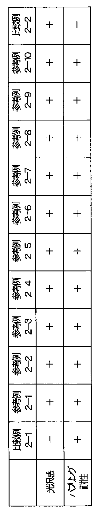
表2に示されたように、金属蒸着層の厚さが10nm以上90nm以下の範囲において、良好なバブリング耐性と優れた金属光沢を伴った液体用紙容器が得られる。
As shown in Table 2, when the thickness of the metal vapor deposition layer is in the range of 10 nm to 90 nm, a liquid paper container with good bubbling resistance and excellent metallic luster can be obtained.
第3の実施形態の参考例および比較例に係る積層シートおよびこれを用いた包装容器を作成した。
<参考例3-1>
水蒸気バリア層として、厚さ6μmのアルミニウム箔と、支持層として厚さ12μmのPETフィルムとを貼り合わせたシートを使用した。このシートのPETフィルム面に押出機からシーラント層として直鎖状低密度ポリエチレン樹脂(LLDPE)を60μmの厚さに押し出して一体化し、内層フィルムを作成した。 A laminated sheet according to the reference example and comparative example of the third embodiment and a packaging container using the same were prepared.
<Reference Example 3-1>
A sheet obtained by bonding an aluminum foil having a thickness of 6 μm and a PET film having a thickness of 12 μm as a support layer was used as the water vapor barrier layer. A linear low density polyethylene resin (LLDPE) as a sealant layer was extruded from the extruder to a thickness of 60 μm and integrated with the PET film surface of the sheet to prepare an inner layer film.
次に厚さ12μmのPETフィルムに厚さ100nmのアルミニウム蒸着層を形成した蒸着フィルムを用意し、蒸着面を回転する研磨ロールに押し当てて蒸着層を貫通するヘアライン状の傷加工を施した。この蒸着面に低密度ポリエチレン樹脂(LDPE)を厚さ18μmとなるように押し出して熱可塑性樹脂層を形成し、さらにこの表面に硝化綿ウレタン系インキを用いて印刷絵柄層を形成した。
Next, a vapor deposition film in which an aluminum vapor deposition layer having a thickness of 100 nm was formed on a PET film having a thickness of 12 μm was prepared. A low-density polyethylene resin (LDPE) was extruded to a thickness of 18 μm on the vapor deposition surface to form a thermoplastic resin layer, and a printed pattern layer was formed on the surface using a nitrified cotton urethane-based ink.
蒸着フィルムの裏面(PET面)と、紙層として坪量380g/m2の厚紙(ノーコートアイボリー)の表面とを、押出機より押し出した接着樹脂(LDPEにEMAA、EAAを添加)を用いて貼り合せた。次にこうして得られた貼り合せ紙と先に作成した内層フィルムとを、同様に押出機から押し出した同じ接着樹脂を用いて貼り合せた。
Using an adhesive resin (added EMAA and EAA to LDPE) extruded from the back of the vapor-deposited film (PET surface) and the surface of thick paper (uncoated ivory) with a basis weight of 380 g / m 2 as a paper layer Pasted together. Next, the bonded paper thus obtained and the previously produced inner layer film were bonded together using the same adhesive resin extruded from the extruder.
以上により得られた積層シートを図14に示す形状に打抜き、口栓を取り付け、図1に示した形状の液体用紙容器を作成した。成型時のヒートシール条件は、温度250℃、圧力0.2MPa、圧締時間1秒とした。成型工程において、バブリングの発生は認められなかった。また得られた紙容器の外観は、高い光輝感をもった金属光沢を有するものであった。
The laminated sheet obtained as described above was punched into the shape shown in FIG. 14, attached with a stopper, and a liquid paper container having the shape shown in FIG. 1 was prepared. The heat sealing conditions at the time of molding were as follows: temperature 250 ° C., pressure 0.2 MPa, and clamping time 1 second. In the molding process, no bubbling was observed. Further, the appearance of the obtained paper container had a metallic luster with a high glitter feeling.
<参考例3-2>
光沢層として、予め表裏面を貫通する針孔加工を施した厚さ6μmのアルミニウム箔を用いた。また表面の熱可塑性樹脂層として厚さ25μmのLLDPEを用いた以外は、参考例3-1と同様にして液体用紙容器を作成した。成型工程において、バブリングの発生は認められなかった。また得られた紙容器の外観は、高い光輝感をもった金属光沢を有すると伴に、針孔加工に基づく独特の意匠性を有するものであった。 <Reference Example 3-2>
As the glossy layer, an aluminum foil having a thickness of 6 μm, which has been subjected to needle hole processing that penetrates the front and back surfaces in advance, was used. A liquid paper container was prepared in the same manner as in Reference Example 3-1, except that LLDPE having a thickness of 25 μm was used as the surface thermoplastic resin layer. In the molding process, no bubbling was observed. In addition, the appearance of the obtained paper container had a unique luster based on needle hole processing as well as having a metallic luster with high glitter.
<参考例3-3>
表面の熱可塑性樹脂層の材質を厚さ20μmのポリプロピレン樹脂(CPP)とした。また光沢層として、坪量23グラム/m2の薄紙に蒸着アンカーコート層を介してアルミニウム蒸着を施した蒸着紙を用い、この表裏面に貫通する針孔加工を施したものを用いた。それ以外は、参考例3-1と同様にして液体用紙容器を作成した。成型工程において、バブリングの発生は認められなかった。また得られた紙容器の外観は、蒸着紙特有の光輝感をもった金属光沢と、独特の意匠性を有するものであった。 <Reference Example 3-3>
The material of the surface thermoplastic resin layer was a polypropylene resin (CPP) having a thickness of 20 μm. Further, as the glossy layer, a thin paper having a basis weight of 23 g / m 2 and a vapor-deposited paper subjected to aluminum vapor deposition through a vapor-deposited anchor coat layer was used, and the front and back surfaces were subjected to needle hole processing. Otherwise, a liquid paper container was prepared in the same manner as in Reference Example 3-1. In the molding process, no bubbling was observed. Further, the appearance of the obtained paper container had a metallic luster having a glitter feeling peculiar to the vapor deposition paper and a unique design.
<参考例3-4>
紙層として、表面に蒸着層を設けた坪量80g/m2の蒸着厚紙を用い、表面にエンボス加工を施して蒸着層に微細なクラックを生じせしめた。この表面に厚さ18μmのLDPE層を形成し、同様に硝化綿ウレタン系インキを用いて、印刷絵柄層を形成した。参考例3-1と同様に作成した内層フィルムと貼り合わせ、積層シートとし、同様にして液体用紙容器を作成した。成型工程において、バブリングの発生は認められなかった。また得られた紙容器の外観は、高い光輝感をもった金属光沢を有すると伴に、エンボス加工に基づく独特の意匠性を有するものであった。 <Reference Example 3-4>
As the paper layer, vapor-deposited cardboard having a basis weight of 80 g / m 2 provided with a vapor-deposited layer on the surface was used, and the surface was embossed to cause fine cracks in the vapor-deposited layer. An LDPE layer having a thickness of 18 μm was formed on this surface, and a printed pattern layer was similarly formed using a nitrified cotton urethane-based ink. A liquid sheet container was prepared in the same manner as above by laminating with an inner layer film prepared in the same manner as in Reference Example 3-1, to form a laminated sheet. In the molding process, no bubbling was observed. In addition, the appearance of the obtained paper container had a unique luster based on embossing as well as having a metallic luster with high glitter.
<比較例3-1>
蒸着フィルムに傷加工を施さなかった以外は、参考例3-1と同様にして、液体用紙容器を作成した。得られた紙容器の外観は、高い光輝感をもった金属光沢を有するものであったが、成型工程において、バブリングの発生が認められた。 <Comparative Example 3-1>
A liquid paper container was prepared in the same manner as Reference Example 3-1, except that the deposited film was not scratched. Although the appearance of the obtained paper container had a metallic luster with a high brightness, the occurrence of bubbling was observed in the molding process.
以上の結果をまとめたものを表3に示す。表中、光沢感の「+」は、高い光輝感をもった金属光沢を有することを意味し、バブリング耐性の「+」、「-」は、それぞれ、バブリングが発生しなかったこと、および、発生したことを意味する。
Table 3 summarizes the above results. In the table, glossy “+” means having a metallic luster with high glossiness, bubbling resistance “+”, “−” means that no bubbling occurred, and Means that it occurred.

表3に示されたように、光沢層に傷加工を施すことにより、良好なバブリング耐性と高い金属光沢を伴った外観を有する液体用紙容器が得られる。
As shown in Table 3, a liquid paper container having an appearance with good bubbling resistance and high metallic luster can be obtained by scratching the glossy layer.
本発明は、液体用紙容器等の包装容器に有用である。
The present invention is useful for packaging containers such as liquid paper containers.
1 液体用紙容器
2 積層シート
3 印刷絵柄層
4 熱可塑性樹脂
5 光沢層
5a 蒸着層
5b 蒸着基材
5P 光沢層の存在する部分
7 接着樹脂層
8 紙基材
9 接着樹脂層
10 水蒸気バリア層
11 シーラント層
12 内層フィルム
16 傷加工
20 側面部
20t トップシール部
20b ボトムシール部
20s サイドシール部 DESCRIPTION OF SYMBOLS 1Liquid paper container 2 Laminated sheet 3 Print pattern layer 4 Thermoplastic resin 5 Glossy layer 5a Vapor deposition layer 5b Vapor deposition base material 5P The part in which the glossy layer exists 7 Adhesive resin layer 8 Paper base material 9 Adhesive resin layer 10 Water vapor barrier layer 11 Sealant Layer 12 Inner layer film 16 Scratch processing 20 Side surface portion 20t Top seal portion 20b Bottom seal portion 20s Side seal portion
2 積層シート
3 印刷絵柄層
4 熱可塑性樹脂
5 光沢層
5a 蒸着層
5b 蒸着基材
5P 光沢層の存在する部分
7 接着樹脂層
8 紙基材
9 接着樹脂層
10 水蒸気バリア層
11 シーラント層
12 内層フィルム
16 傷加工
20 側面部
20t トップシール部
20b ボトムシール部
20s サイドシール部 DESCRIPTION OF SYMBOLS 1
Claims (5)
- シート材の2つの側縁が重なってヒートシールされてなる筒状体の各端部を含む領域がそれぞれ折りたたまれ且つヒートシールされてなる頂部および底面を有する包装容器の製造に用いる積層シートであって、
前記頂部に対応する領域であるトップシール部と、
前記底面に対応する領域であるボトムシール部と、
前記トップシール部および前記ボトムシール部に挟まれた領域である側面部とを有し、
前記包装容器の内方となる側から順に、水蒸気バリア層およびシーラント層を有する内層フィルムと、紙基材と、熱可塑性樹脂層とを含み、
前記紙基材と前記熱可塑性樹脂層との間には、前記トップシール部または前記ボトムシール部に含まれる少なくとも一部の領域を除いて、光沢層が設けられる、積層シート。 It is a laminated sheet used for manufacturing a packaging container having a top part and a bottom part, each of which includes an end part of a tubular body that is heat-sealed by overlapping two side edges of the sheet material and is folded and heat-sealed. And
A top seal portion which is a region corresponding to the top portion;
A bottom seal portion that is a region corresponding to the bottom surface;
Having a side part that is a region sandwiched between the top seal part and the bottom seal part,
In order from the inner side of the packaging container, including an inner layer film having a water vapor barrier layer and a sealant layer, a paper substrate, and a thermoplastic resin layer,
A laminated sheet in which a gloss layer is provided between the paper base material and the thermoplastic resin layer except for at least a part of the region included in the top seal portion or the bottom seal portion. - 前記ボトムシール部は、前記側面部との境界側端縁から所定距離以内の範囲に前記光沢層が設けられ、前記所定距離を超える範囲には前記光沢層が設けられていない、請求項1に記載の積層シート。 2. The bottom seal portion according to claim 1, wherein the gloss layer is provided in a range within a predetermined distance from a boundary side edge with the side surface portion, and the gloss layer is not provided in a range exceeding the predetermined distance. The laminated sheet described.
- 前記光沢層は、10nm以上90nm以下の金属蒸着層である、請求項1または2に記載の積層シート。 The laminated sheet according to claim 1 or 2, wherein the glossy layer is a metal vapor deposition layer having a thickness of 10 nm to 90 nm.
- 前記光沢層には、貫通する傷が形成されている、請求項1~3のいずれかに記載の積層シート。 The laminated sheet according to any one of claims 1 to 3, wherein a penetrating flaw is formed in the glossy layer.
- 請求項1~4のいずれかに記載の積層シートの2つの側縁どうしをヒートシールした包装容器スリーブ。 A packaging container sleeve in which two side edges of the laminated sheet according to any one of claims 1 to 4 are heat-sealed.
Priority Applications (2)
| Application Number | Priority Date | Filing Date | Title |
|---|---|---|---|
| CN201780009218.5A CN108602580B (en) | 2016-02-03 | 2017-01-25 | Laminated sheet and packaging container sleeve |
| US16/021,798 US10549507B2 (en) | 2016-02-03 | 2018-06-28 | Laminate sheet and packaging container sleeve |
Applications Claiming Priority (6)
| Application Number | Priority Date | Filing Date | Title |
|---|---|---|---|
| JP2016-018874 | 2016-02-03 | ||
| JP2016018874A JP2017137088A (en) | 2016-02-03 | 2016-02-03 | Paper container for liquid |
| JP2016022458A JP6740626B2 (en) | 2016-02-09 | 2016-02-09 | Liquid paper container |
| JP2016-022458 | 2016-02-09 | ||
| JP2016-033216 | 2016-02-24 | ||
| JP2016033216A JP6798114B2 (en) | 2016-02-24 | 2016-02-24 | Liquid paper container and its manufacturing method |
Related Child Applications (1)
| Application Number | Title | Priority Date | Filing Date |
|---|---|---|---|
| US16/021,798 Continuation US10549507B2 (en) | 2016-02-03 | 2018-06-28 | Laminate sheet and packaging container sleeve |
Publications (1)
| Publication Number | Publication Date |
|---|---|
| WO2017135124A1 true WO2017135124A1 (en) | 2017-08-10 |
Family
ID=59499783
Family Applications (1)
| Application Number | Title | Priority Date | Filing Date |
|---|---|---|---|
| PCT/JP2017/002555 WO2017135124A1 (en) | 2016-02-03 | 2017-01-25 | Laminated sheet and packaging container sleeve |
Country Status (3)
| Country | Link |
|---|---|
| US (1) | US10549507B2 (en) |
| CN (1) | CN108602580B (en) |
| WO (1) | WO2017135124A1 (en) |
Families Citing this family (2)
| Publication number | Priority date | Publication date | Assignee | Title |
|---|---|---|---|---|
| WO2019045019A1 (en) * | 2017-08-31 | 2019-03-07 | 大日本印刷株式会社 | Bag |
| JP1672409S (en) * | 2019-12-05 | 2020-11-09 |
Citations (7)
| Publication number | Priority date | Publication date | Assignee | Title |
|---|---|---|---|---|
| JPH0375129U (en) * | 1989-11-28 | 1991-07-29 | ||
| JPH04109017U (en) * | 1991-03-08 | 1992-09-21 | 大日本印刷株式会社 | paper liquid container |
| US20080023534A1 (en) * | 2006-07-28 | 2008-01-31 | Brpp, Llc | Gable top container with perforated opening arrangement |
| JP2009073502A (en) * | 2007-09-19 | 2009-04-09 | Toppan Printing Co Ltd | Laminating material for paper container, and paper container prepared by using the same |
| JP2010052761A (en) * | 2008-08-28 | 2010-03-11 | Toppan Printing Co Ltd | Paper container |
| JP2013203454A (en) * | 2012-03-29 | 2013-10-07 | Dainippon Printing Co Ltd | Paper container for liquid |
| JP2014031186A (en) * | 2012-08-02 | 2014-02-20 | Toppan Printing Co Ltd | Paper container for liquid |
Family Cites Families (11)
| Publication number | Priority date | Publication date | Assignee | Title |
|---|---|---|---|---|
| US4838432A (en) * | 1987-10-13 | 1989-06-13 | Somerville Packaging Corporation | Carton and blank for packaging ice cream and the like |
| JPH0375129A (en) * | 1989-08-15 | 1991-03-29 | Mitsubishi Motors Corp | Method for molding composite material |
| US5078313A (en) * | 1990-07-11 | 1992-01-07 | Sweetheart Cup Company Inc. | Wax-coated paperboard containers |
| DE4102021C2 (en) * | 1991-01-24 | 1995-01-05 | Pkl Verpackungssysteme Gmbh | Process for producing a folding box pack from a liquid-tight, heat-sealable, coated cardboard composite material |
| JPH11334756A (en) * | 1998-05-22 | 1999-12-07 | Nihon Tetrapak Kk | Semi-material for paper container, production of semi-material for paper container, paper container packaging material and paper container |
| JP4508441B2 (en) * | 2001-02-16 | 2010-07-21 | 新日鐵化学株式会社 | Laminated body and method for producing the same |
| JP2002370307A (en) | 2001-06-18 | 2002-12-24 | Nihon Tetra Pak Kk | Laminated packaging material and paper container for liquid |
| US6601757B2 (en) * | 2001-06-21 | 2003-08-05 | The Lindy Bowman Co., | Integrated rigid set up gift box |
| JP2006527111A (en) * | 2003-06-10 | 2006-11-30 | ソンクック チャ | Insulation sheet and manufacturing method thereof |
| JP2005288966A (en) * | 2004-04-02 | 2005-10-20 | Mitsui Mining & Smelting Co Ltd | Manufacturing method for double-sided metal-clad laminate, and double-sided metal-clad laminate obtained by the manufacturing method |
| US7905388B2 (en) * | 2004-12-13 | 2011-03-15 | Lindy Bowman Company | Pre-lined rigid set-up box |
-
2017
- 2017-01-25 CN CN201780009218.5A patent/CN108602580B/en not_active Expired - Fee Related
- 2017-01-25 WO PCT/JP2017/002555 patent/WO2017135124A1/en active Application Filing
-
2018
- 2018-06-28 US US16/021,798 patent/US10549507B2/en not_active Expired - Fee Related
Patent Citations (7)
| Publication number | Priority date | Publication date | Assignee | Title |
|---|---|---|---|---|
| JPH0375129U (en) * | 1989-11-28 | 1991-07-29 | ||
| JPH04109017U (en) * | 1991-03-08 | 1992-09-21 | 大日本印刷株式会社 | paper liquid container |
| US20080023534A1 (en) * | 2006-07-28 | 2008-01-31 | Brpp, Llc | Gable top container with perforated opening arrangement |
| JP2009073502A (en) * | 2007-09-19 | 2009-04-09 | Toppan Printing Co Ltd | Laminating material for paper container, and paper container prepared by using the same |
| JP2010052761A (en) * | 2008-08-28 | 2010-03-11 | Toppan Printing Co Ltd | Paper container |
| JP2013203454A (en) * | 2012-03-29 | 2013-10-07 | Dainippon Printing Co Ltd | Paper container for liquid |
| JP2014031186A (en) * | 2012-08-02 | 2014-02-20 | Toppan Printing Co Ltd | Paper container for liquid |
Also Published As
| Publication number | Publication date |
|---|---|
| CN108602580B (en) | 2020-11-17 |
| US20180304587A1 (en) | 2018-10-25 |
| US10549507B2 (en) | 2020-02-04 |
| CN108602580A (en) | 2018-09-28 |
Similar Documents
| Publication | Publication Date | Title |
|---|---|---|
| JP6685994B2 (en) | Method for manufacturing laminated packaging material and laminated packaging material | |
| AU2003234788A1 (en) | Method for producing lightproof paper packaging material, lightproof paper packaging material, semi-paper packaging material and lightproof paper packaging container | |
| WO2017135124A1 (en) | Laminated sheet and packaging container sleeve | |
| JP2009073502A (en) | Laminating material for paper container, and paper container prepared by using the same | |
| JP2010052761A (en) | Paper container | |
| US10086595B2 (en) | Method for forming packaging material, packaging material and use thereof | |
| JP2007176539A (en) | Paper container, and method for manufacturing paper container | |
| JP2002068179A (en) | Packaging material for sealing paper container | |
| JP4155426B2 (en) | Packaging materials for paper containers | |
| JP5768585B2 (en) | Shrink film, packaging container with shrink film, and manufacturing method thereof | |
| JP4544622B2 (en) | Polybutylene terephthalate film laminate and use thereof | |
| JP6798114B2 (en) | Liquid paper container and its manufacturing method | |
| JP2006315741A (en) | Water-proof paper tray | |
| JP6740626B2 (en) | Liquid paper container | |
| JP2007022613A (en) | High design property paper cup | |
| JPH10745A (en) | Laminated and packaging container using laminate | |
| JP7087870B2 (en) | Packaging material | |
| JP2017217814A (en) | Production method of cylindrical paper container | |
| JP2018176441A (en) | Laminate and paper container for liquid using the same | |
| JP4039537B2 (en) | Paper container base paper, paper container base paper manufacturing method, paper container packaging and paper container | |
| JPH03295B2 (en) | ||
| JP2017137088A (en) | Paper container for liquid | |
| JP2008230690A (en) | Shading lid material and manufacturing method thereof | |
| JP2013010527A (en) | Paper container | |
| JP2001191411A (en) | Method for preparing semi-material for paper container and packaging material for paper container |
Legal Events
| Date | Code | Title | Description |
|---|---|---|---|
| 121 | Ep: the epo has been informed by wipo that ep was designated in this application |
Ref document number: 17747283 Country of ref document: EP Kind code of ref document: A1 |
|
| NENP | Non-entry into the national phase |
Ref country code: DE |
|
| 122 | Ep: pct application non-entry in european phase |
Ref document number: 17747283 Country of ref document: EP Kind code of ref document: A1 |