WO2017131389A1 - Procédé d'allocation de ressource radio dans un système de communication sans fil et dispositif associé - Google Patents
Procédé d'allocation de ressource radio dans un système de communication sans fil et dispositif associé Download PDFInfo
- Publication number
- WO2017131389A1 WO2017131389A1 PCT/KR2017/000666 KR2017000666W WO2017131389A1 WO 2017131389 A1 WO2017131389 A1 WO 2017131389A1 KR 2017000666 W KR2017000666 W KR 2017000666W WO 2017131389 A1 WO2017131389 A1 WO 2017131389A1
- Authority
- WO
- WIPO (PCT)
- Prior art keywords
- message
- sps
- resource
- information
- base station
- Prior art date
Links
Images


Classifications
-
- H—ELECTRICITY
- H04—ELECTRIC COMMUNICATION TECHNIQUE
- H04W—WIRELESS COMMUNICATION NETWORKS
- H04W72/00—Local resource management
- H04W72/20—Control channels or signalling for resource management
- H04W72/21—Control channels or signalling for resource management in the uplink direction of a wireless link, i.e. towards the network
-
- H—ELECTRICITY
- H04—ELECTRIC COMMUNICATION TECHNIQUE
- H04W—WIRELESS COMMUNICATION NETWORKS
- H04W72/00—Local resource management
- H04W72/12—Wireless traffic scheduling
- H04W72/1263—Mapping of traffic onto schedule, e.g. scheduled allocation or multiplexing of flows
- H04W72/1268—Mapping of traffic onto schedule, e.g. scheduled allocation or multiplexing of flows of uplink data flows
-
- H—ELECTRICITY
- H04—ELECTRIC COMMUNICATION TECHNIQUE
- H04W—WIRELESS COMMUNICATION NETWORKS
- H04W72/00—Local resource management
- H04W72/20—Control channels or signalling for resource management
- H04W72/23—Control channels or signalling for resource management in the downlink direction of a wireless link, i.e. towards a terminal
-
- H—ELECTRICITY
- H04—ELECTRIC COMMUNICATION TECHNIQUE
- H04W—WIRELESS COMMUNICATION NETWORKS
- H04W4/00—Services specially adapted for wireless communication networks; Facilities therefor
- H04W4/30—Services specially adapted for particular environments, situations or purposes
- H04W4/40—Services specially adapted for particular environments, situations or purposes for vehicles, e.g. vehicle-to-pedestrians [V2P]
Definitions
- the present invention relates to a wireless communication system, and more particularly, to a method for allocating Semi-Persistent Scheduling resources and an apparatus supporting the same.
- Mobile communication systems have been developed to provide voice services while ensuring user activity.
- the mobile communication system has expanded not only voice but also data service.As a result of the explosive increase in traffic, a shortage of resources and users are demanding higher speed services, a more advanced mobile communication system is required. have.
- the base station In a situation where transmission using Semi-Persistent Scheduling (SPS) is performed, the base station cannot know the generation timing of uplink data transmitted from the terminal. Accordingly, there is a problem that the base station can not allocate the optimized SPS UL resources for the transmission of uplink data to the terminal.
- SPS Semi-Persistent Scheduling
- an object of the present invention is to propose a method for allocating an optimized SPS UL radio resource from a base station in a wireless communication system.
- the present invention proposes a method in which a terminal reports information on a generation time and / or generation period of uplink data to a base station.
- the present invention proposes a method for transmitting a scheduling request (SR) to the base station when the SPS is set in order for the base station to implicitly know the generation time of uplink data.
- SR scheduling request
- the present invention proposes a method for directly requesting a radio resource, which a terminal prefers (or required) to transmit uplink data, to a base station.
- the terminal calculates the offset (offset) between the generation time of uplink data and the SPS resource allocation time, and reports the information on the calculated offset to the base station Suggest a method.
- the method performed by the terminal may include an uplink grant associated with semi-persistent signaling (SPS) from a base station. before receiving an uplink grant, transmitting a first message for requesting allocation of SPS resources for semi-continuous transmission of a specific uplink message to the base station, and SPS allocated according to the request for allocation of the SPS resources. Receiving a second message including information on a resource; and transmitting the specific uplink message to the base station by using an SPS resource identified using the received information.
- the message is first information indicating a time or period in which the specific uplink message is generated or the specific uplink message.
- the transmission may include at least one of second information that indicates a time when.
- the specific uplink message may include a message related to safety in a vehicle to everything (V2X) system.
- V2X vehicle to everything
- the transmitting of the first message may include transmitting a scheduling request for requesting allocation of the SPS resource.
- the information on the allocated SPS resources included in the second message may further include offset information related to a subsequent SPS resource allocation.
- the second message may be periodically received from the base station at a time determined according to a specific equation.
- the second information may include at least one of an upper value of a specific time point or an allocation time of the SPS resource and a lower bound of an allocation time of the SPS resource.
- each of the upper limit value and the lower limit value may be expressed by at least one of a system frame number and a subframe number.
- the step of transmitting the first message requesting the allocation of the SPS resource for semi-continuously transmitting the specific uplink message to the base station to monitor the message for the allocation of the SPS resource And driving the set timer and transmitting the first message to the base station when the timer expires.
- the method may further include receiving a third message from the base station, the third message including information on another SPS resource transmitted according to at least one of a period or an offset that is changed based on the allocation request of the SPS resource. It may include.
- a terminal to which a radio resource is allocated may include a transceiver for transmitting and receiving a radio signal and a processor functionally connected to the transceiver.
- the processor allocates an SPS resource for semi-continuously transmitting a specific uplink message before receiving an uplink grant related to semi-persistent signaling (SPS) from a base station. Transmits a first message requesting a message to the base station, receives a second message including information on an SPS resource allocated according to the SPS resource allocation request, and uses the received information to identify an SPS resource.
- the specific uplink message may be controlled to be transmitted to the base station.
- the first message may include at least one of first information indicating a time point or period in which the specific uplink message is generated or second information indicating a time point for transmitting the specific uplink message.
- a time point of generating uplink data (UL data) and actually transmitting UL data can be reduced.
- FIG. 1 illustrates a structure of a radio frame in a wireless communication system to which the present invention can be applied.
- FIG. 2 is a diagram illustrating a resource grid for one downlink slot in a wireless communication system to which the present invention can be applied.
- FIG. 3 shows a structure of a downlink subframe in a wireless communication system to which the present invention can be applied.
- FIG. 4 shows a structure of an uplink subframe in a wireless communication system to which the present invention can be applied.
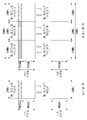
- FIG. 5 shows an example of a form in which PUCCH formats are mapped to a PUCCH region of an uplink physical resource block in a wireless communication system to which the present invention can be applied.
- FIG. 6 shows a structure of a CQI channel in the case of a normal CP in a wireless communication system to which the present invention can be applied.
- FIG. 7 shows a structure of an ACK / NACK channel in case of a normal CP in a wireless communication system to which the present invention can be applied.
- FIG. 8 shows an example of transport channel processing of an UL-SCH in a wireless communication system to which the present invention can be applied.
- FIG. 9 shows an example of a signal processing procedure of an uplink shared channel which is a transport channel in a wireless communication system to which the present invention can be applied.
- FIG. 10 illustrates a reference signal pattern mapped to a downlink resource block pair in a wireless communication system to which the present invention can be applied.
- FIG. 11 illustrates an uplink subframe including a sounding reference signal symbol in a wireless communication system to which the present invention can be applied.
- FIG. 12 shows an example of a component carrier and carrier aggregation in a wireless communication system to which the present invention can be applied.
- FIG. 13 illustrates an example of a subframe structure according to cross carrier scheduling in a wireless communication system to which the present invention can be applied.
- FIG. 14 illustrates an example of generating and transmitting five SC-FDMA symbols during one slot in a wireless communication system to which the present invention can be applied.
- 15 is a diagram illustrating a time-frequency resource block in the time frequency domain of a wireless communication system to which the present invention can be applied.
- FIG. 16 is a diagram illustrating a resource allocation and retransmission process of an asynchronous HARQ scheme in a wireless communication system to which the present invention can be applied.
- 17 is a diagram illustrating a carrier aggregation based CoMP system in a wireless communication system to which the present invention can be applied.
- FIG. 19 is a diagram for explaining elements of a D2D technique.
- 20 is a diagram illustrating an embodiment of a configuration of a resource unit.
- 21 illustrates a case where an SA resource pool and a subsequent data channel resource pool appear periodically.
- 22 to 24 are diagrams showing an example of a relay process and resources for relay to which the present invention can be applied.
- 25 illustrates a method for requesting SPS resource allocation according to an embodiment of the present invention.
- 26 illustrates a method for requesting SPS resource allocation according to another embodiment of the present invention.
- FIG. 27 illustrates a method for requesting SPS resource allocation according to another embodiment of the present invention.
- FIG. 28 is a flowchart illustrating an operation of a terminal for requesting SPS resource allocation according to various embodiments of the present disclosure.
- 29 is a block diagram illustrating a wireless communication device according to one embodiment of the present invention.
- a base station has a meaning as a terminal node of a network that directly communicates with a terminal.
- the specific operation described as performed by the base station in this document may be performed by an upper node of the base station in some cases. That is, it is obvious that various operations performed for communication with a terminal in a network composed of a plurality of network nodes including a base station may be performed by the base station or other network nodes other than the base station.
- a 'base station (BS)' may be replaced by terms such as a fixed station, a Node B, an evolved-NodeB (eNB), a base transceiver system (BTS), an access point (AP), and the like. .
- a 'terminal' may be fixed or mobile, and may include a user equipment (UE), a mobile station (MS), a user terminal (UT), a mobile subscriber station (MSS), a subscriber station (SS), and an AMS ( Advanced Mobile Station (WT), Wireless Terminal (WT), Machine-Type Communication (MTC) Device, Machine-to-Machine (M2M) Device, Device-to-Device (D2D) Device, etc.
- UE user equipment
- MS mobile station
- UT user terminal
- MSS mobile subscriber station
- SS subscriber station
- AMS Advanced Mobile Station
- WT Wireless Terminal
- MTC Machine-Type Communication
- M2M Machine-to-Machine
- D2D Device-to-Device
- downlink means communication from a base station to a terminal
- uplink means communication from a terminal to a base station.
- a transmitter may be part of a base station, and a receiver may be part of a terminal.
- a transmitter may be part of a terminal and a receiver may be part of a base station.
- CDMA code division multiple access
- FDMA frequency division multiple access
- TDMA time division multiple access
- OFDMA orthogonal frequency division multiple access
- SC-FDMA single carrier frequency division multiple access
- GSM global system for mobile communications
- GPRS general packet radio service
- EDGE enhanced data rates for GSM evolution
- OFDMA may be implemented in a wireless technology such as IEEE 802.11 (Wi-Fi), IEEE 802.16 (WiMAX), IEEE 802-20, evolved UTRA (E-UTRA).
- UTRA is part of a universal mobile telecommunications system (UMTS).
- 3rd generation partnership project (3GPP) long term evolution (LTE) is a part of evolved UMTS (E-UMTS) using E-UTRA, and employs OFDMA in downlink and SC-FDMA in uplink.
- LTE-A (advanced) is the evolution of 3GPP LTE.
- Embodiments of the present invention may be supported by standard documents disclosed in at least one of the wireless access systems IEEE 802, 3GPP and 3GPP2. That is, steps or parts which are not described to clearly reveal the technical spirit of the present invention among the embodiments of the present invention may be supported by the above documents. In addition, all terms disclosed in the present document can be described by the above standard document.
- FIG. 1 illustrates a structure of a radio frame in a wireless communication system to which the present invention can be applied.
- 3GPP LTE / LTE-A supports a type 1 radio frame structure applicable to frequency division duplex (FDD) and a type 2 radio frame structure applicable to time division duplex (TDD).
- FDD frequency division duplex
- TDD time division duplex
- Type 1A illustrates the structure of a type 1 radio frame.
- Type 1 radio frames may be applied to both full duplex and half duplex FDD.
- a radio frame consists of 10 subframes.
- One subframe consists of two consecutive slots in the time domain, and subframe i consists of slot 2i and slot 2i + 1.
- the time taken to transmit one subframe is called a transmission time interval (TTI).
- TTI transmission time interval
- one subframe may have a length of 1 ms and one slot may have a length of 0.5 ms.
- uplink transmission and downlink transmission are distinguished in the frequency domain. While there is no restriction on full-duplex FDD, the terminal cannot simultaneously transmit and receive in half-duplex FDD operation.
- One slot includes a plurality of orthogonal frequency division multiplexing (OFDM) symbols in the time domain and a plurality of resource blocks (RBs) in the frequency domain. Since 3GPP LTE uses OFDMA in downlink, the OFDM symbol is for representing one symbol period. The OFDM symbol may be referred to as one SC-FDMA symbol or symbol period.
- a resource block is a resource allocation unit and includes a plurality of consecutive subcarriers in one slot.
- FIG. 1B illustrates a frame structure type 2.
- an uplink-downlink configuration is a rule indicating whether uplink and downlink are allocated (or reserved) for all subframes.
- Table 1 shows an uplink-downlink configuration.
- 'D' represents a subframe for downlink transmission
- 'U' represents a subframe for uplink transmission
- 'S' represents a downlink pilot.
- a special subframe consisting of three fields: a time slot, a guard period (GP), and an uplink pilot time slot (UpPTS).
- DwPTS is used for initial cell search, synchronization or channel estimation at the terminal.
- UpPTS is used for channel estimation at the base station and synchronization of uplink transmission of the terminal.
- GP is a section for removing interference caused in the uplink due to the multipath delay of the downlink signal between the uplink and the downlink.
- the uplink-downlink configuration can be classified into seven types, and the location and / or number of downlink subframes, special subframes, and uplink subframes are different for each configuration.
- Switch-point periodicity refers to a period in which an uplink subframe and a downlink subframe are repeatedly switched in the same manner, and both 5ms or 10ms are supported.
- the special subframe S exists every half-frame, and in case of having a period of 5ms downlink-uplink switching time, it exists only in the first half-frame.
- subframes 0 and 5 and DwPTS are sections for downlink transmission only.
- the subframe immediately following the UpPTS and the subframe subframe is always an interval for uplink transmission.
- the uplink-downlink configuration may be known to both the base station and the terminal as system information.
- the base station may notify the terminal of the change of the uplink-downlink allocation state of the radio frame by transmitting only an index of the configuration information.
- the configuration information is a kind of downlink control information and may be transmitted through a physical downlink control channel (PDCCH) like other scheduling information, and is commonly transmitted to all terminals in a cell through a broadcast channel as broadcast information. May be
- PDCCH physical downlink control channel
- Table 2 shows the configuration of the special subframe (length of DwPTS / GP / UpPTS).
- the structure of a radio frame according to the example of FIG. 1 is just one example, and the number of subcarriers included in the radio frame or the number of slots included in the subframe and the number of OFDM symbols included in the slot may vary. Can be.
- FIG. 2 is a diagram illustrating a resource grid for one downlink slot in a wireless communication system to which the present invention can be applied.
- one downlink slot includes a plurality of OFDM symbols in the time domain.
- one downlink slot includes seven OFDM symbols, and one resource block includes 12 subcarriers in a frequency domain, but is not limited thereto.
- Each element on the resource grid is a resource element, and one resource block (RB) includes 12 ⁇ 7 resource elements.
- the number N ⁇ DL of resource blocks included in the downlink slot depends on the downlink transmission bandwidth.
- the structure of the uplink slot may be the same as the structure of the downlink slot.
- FIG. 3 shows a structure of a downlink subframe in a wireless communication system to which the present invention can be applied.
- up to three OFDM symbols in the first slot in a subframe are control regions to which control channels are allocated, and the remaining OFDM symbols are data regions to which PDSCH (Physical Downlink Shared Channel) is allocated. data region).
- PDSCH Physical Downlink Shared Channel
- An example of a downlink control channel used in 3GPP LTE includes a physical control format indicator channel (PCFICH), a physical downlink control channel (PDCCH), a physical hybrid-ARQ indicator channel (PHICH), and the like.
- the PCFICH is transmitted in the first OFDM symbol of a subframe and carries information about the number of OFDM symbols (ie, the size of the control region) used for transmission of control channels within the subframe.
- the PHICH is a response channel for the uplink and carries an ACK (Acknowledgement) / NACK (Not-Acknowledgement) signal for a hybrid automatic repeat request (HARQ).
- Control information transmitted through the PDCCH is called downlink control information (DCI).
- the downlink control information includes uplink resource allocation information, downlink resource allocation information or an uplink transmission (Tx) power control command for a certain terminal group.
- the PDCCH is a resource allocation and transmission format of DL-SCH (Downlink Shared Channel) (also referred to as a downlink grant), resource allocation information of UL-SCH (Uplink Shared Channel) (also called an uplink grant), and PCH ( Paging information in paging channel, system information in DL-SCH, resource allocation for upper-layer control message such as random access response transmitted in PDSCH, arbitrary terminal It may carry a set of transmission power control commands for the individual terminals in the group, activation of Voice over IP (VoIP), and the like.
- the plurality of PDCCHs may be transmitted in the control region, and the terminal may monitor the plurality of PDCCHs.
- the PDCCH consists of a set of one or a plurality of consecutive CCEs.
- CCE is a logical allocation unit used to provide a PDCCH with a coding rate according to the state of a radio channel.
- the CCE corresponds to a plurality of resource element groups.
- the format of the PDCCH and the number of available bits of the PDCCH are determined according to the association between the number of CCEs and the coding rate provided by the CCEs.
- the base station determines the PDCCH format according to the DCI to be transmitted to the terminal, and attaches a CRC (Cyclic Redundancy Check) to the control information.
- the CRC is masked with a unique identifier (referred to as RNTI (Radio Network Temporary Identifier)) according to the owner or purpose of the PDCCH.
- RNTI Radio Network Temporary Identifier
- a unique identifier of the terminal for example, a C-RNTI (Cell-RNTI) may be masked to the CRC.
- a paging indication identifier for example, P-RNTI (P-RNTI) may be masked to the CRC.
- the system information more specifically, the PDCCH for the system information block (SIB), the system information identifier and the system information RNTI (SI-RNTI) may be masked to the CRC.
- SI-RNTI system information RNTI
- RA-RNTI random access-RNTI
- Enhanced PDCCH carries UE-specific signaling.
- the EPDCCH is located in a physical resource block (PRB) that is UE-specifically configured.
- PRB physical resource block
- the PDCCH may be transmitted in up to three OFDM symbols in the first slot in the subframe, but the EPDCCH may be transmitted in a resource region other than the PDCCH.
- the start time (ie, symbol) of the EPDCCH in the subframe may be configured in the terminal through higher layer signaling (eg, RRC signaling, etc.).
- EPDCCH is a transport format associated with the DL-SCH, resource allocation and HARQ information, a transport format associated with the UL-SCH, resource allocation and HARQ information, resource allocation associated with Side-link Shared Channel (SL-SCH) and Physical Sidelink Control Channel (PSCCH) Can carry information, etc.
- Multiple EPDCCHs may be supported and the UE may monitor a set of EPCCHs.
- the EPDCCH may be transmitted using one or more consecutive enhanced CCEs (ECCEs), and the number of ECCEs per single EPDCCH may be determined for each EPDCCH format.
- ECCEs enhanced CCEs
- Each ECCE may be composed of a plurality of enhanced resource element groups (EREGs).
- EREG is used to define the mapping of ECCE to RE.
- the terminal may monitor the plurality of EPDCCHs. For example, one or two EPDCCH sets in one PRB pair in which the UE monitors EPDCCH transmission may be configured.
- the EPCCH may use localized transmission or distributed transmission, so that the mapping of ECCE to the RE in the PRB may be different.
- FIG. 4 shows a structure of an uplink subframe in a wireless communication system to which the present invention can be applied.
- an uplink subframe may be divided into a control region and a data region in the frequency domain.
- a physical uplink control channel (PUCCH) carrying uplink control information is allocated to the control region.
- the data region is allocated a Physical Uplink Shared Channel (PUSCH) that carries user data.
- PUCCH Physical Uplink Control Channel
- PUSCH Physical Uplink Shared Channel
- a PUCCH for one UE is allocated a resource block (RB) pair in a subframe.
- RBs belonging to the RB pair occupy different subcarriers in each of the two slots.
- This RB pair allocated to the PUCCH is said to be frequency hopping at the slot boundary (slot boundary).
- PUCCH Physical Uplink Control Channel
- the uplink control information (UCI) transmitted through the PUCCH may include a scheduling request (SR), HARQ ACK / NACK information, and downlink channel measurement information as follows.
- SR scheduling request
- HARQ ACK / NACK information HARQ ACK / NACK information
- SR Service Request: Information used for requesting an uplink UL-SCH resource. It is transmitted using OOK (On-off Keying) method.
- HARQ ACK / NACK This is a response signal for a downlink data packet on a PDSCH. Indicates whether the downlink data packet was successfully received. One bit of ACK / NACK is transmitted in response to a single downlink codeword, and two bits of ACK / NACK are transmitted in response to two downlink codewords.
- the CSI may include at least one of a channel quality indicator (CQI), a rank indicator (RI), a precoding matrix indicator (PMI), and a precoding type indicator (PTI). 20 bits are used per subframe.
- CQI channel quality indicator
- RI rank indicator
- PMI precoding matrix indicator
- PTI precoding type indicator
- HARQ ACK / NACK information may be generated according to whether the decoding of the downlink data packet on the PDSCH is successful.
- one bit is transmitted as ACK / NACK information for downlink single codeword transmission, and two bits are transmitted as ACK / NACK information for downlink 2 codeword transmission.
- Channel measurement information refers to feedback information related to a multiple input multiple output (MIMO) technique, and includes channel quality indicator (CQI), precoding matrix index (PMI), and rank indicator (RI). : Rank Indicator) may be included. These channel measurement information may be collectively expressed as CQI.
- CQI channel quality indicator
- PMI precoding matrix index
- RI rank indicator
- 20 bits per subframe may be used for transmission of the CQI.
- PUCCH may be modulated using Binary Phase Shift Keying (BPSK) and Quadrature Phase Shift Keying (QPSK).
- Control information of a plurality of terminals may be transmitted through a PUCCH, and a constant amplitude zero autocorrelation (CAZAC) sequence having a length of 12 is performed when code division multiplexing (CDM) is performed to distinguish signals of respective terminals.
- CAZAC sequence has a characteristic of maintaining a constant amplitude in the time domain and the frequency domain, the coverage is reduced by reducing the Peak-to-Average Power Ratio (PAPR) or the Cubic Metric (CM) of the UE. It has a suitable property to increase.
- PAPR Peak-to-Average Power Ratio
- CM Cubic Metric
- ACK / NACK information for downlink data transmission transmitted through the PUCCH is covered using an orthogonal sequence or an orthogonal cover (OC).
- control information transmitted on the PUCCH may be distinguished using a cyclically shifted sequence having different cyclic shift (CS) values.
- the cyclically shifted sequence may be generated by cyclically shifting a base sequence by a specific cyclic shift amount.
- the specific CS amount is indicated by the cyclic shift index (CS index).
- the number of cyclic shifts available may vary depending on the delay spread of the channel.
- Various kinds of sequences may be used as the base sequence, and the above-described CAZAC sequence is one example.
- control information that can be transmitted in one subframe by the UE depends on the number of SC-FDMA symbols available for transmission of the control information (that is, RS transmission for coherent detection of PUCCH). SC-FDMA symbols except for the SC-FDMA symbol used).
- PUCCH is defined in seven different formats according to transmitted control information, modulation scheme, amount of control information, and the like, and according to uplink control information (UCI) transmitted according to each PUCCH format,
- UCI uplink control information
- PUCCH format 1 is used for single transmission of SR.
- an unmodulated waveform is applied, which will be described later in detail.
- PUCCH format 1a or 1b is used for transmission of HARQ ACK / NACK.
- PUCCH format 1a or 1b may be used.
- HARQ ACK / NACK and SR may be transmitted in the same subframe using PUCCH format 1a or 1b.
- PUCCH format 2 is used for transmission of CQI, and PUCCH format 2a or 2b is used for transmission of CQI and HARQ ACK / NACK. In the case of an extended CP, PUCCH format 2 may be used for transmission of CQI and HARQ ACK / NACK.
- PUCCH format 3 is used to carry 48 bits of encoded UCI.
- PUCCH format 3 may carry HARQ ACK / NACK for a plurality of serving cells, SR (if present), and CSI report for one serving cell.
- FIG. 8 shows an example of a form in which PUCCH formats are mapped to a PUCCH region of an uplink physical resource block in a wireless communication system to which the present invention can be applied.
- N_RB ⁇ UL denotes the number of resource blocks in uplink
- 0, 1, ..., N_RB ⁇ UL-1 denotes the number of physical resource blocks.
- the PUCCH is mapped to both edges of the uplink frequency block.
- the number of PUCCH RBs (N_RB ⁇ (2)) usable by the PUCCH format 2 / 2a / 2b may be indicated to terminals in a cell by broadcasting signaling.
- PUCCH format 2 / 2a / 2b is a control channel for transmitting channel measurement feedback (CQI, PMI, RI).
- the reporting period of the channel measurement feedback (hereinafter, collectively referred to as CQI information) and the frequency unit (or frequency resolution) to be measured may be controlled by the base station.
- CQI information channel measurement feedback
- the frequency unit (or frequency resolution) to be measured may be controlled by the base station.
- Periodic and aperiodic CQI reporting can be supported in the time domain.
- PUCCH format 2 may be used only for periodic reporting and PUSCH may be used for aperiodic reporting.
- the base station may instruct the terminal to transmit an individual CQI report on a resource scheduled for uplink data transmission.
- FIG. 6 shows a structure of a CQI channel in the case of a normal CP in a wireless communication system to which the present invention can be applied.
- SC-FDMA symbols 0 to 6 of one slot SC-FDMA symbols 1 and 5 (second and sixth symbols) are used for demodulation reference signal (DMRS) transmission, and CQI in the remaining SC-FDMA symbols. Information can be transmitted. Meanwhile, in the case of an extended CP, one SC-FDMA symbol (SC-FDMA symbol 3) is used for DMRS transmission.
- SC-FDMA symbol 3 SC-FDMA symbol 3
- DMRS Reference signal
- CQI information is carried on the remaining five SC-FDMA symbols.
- Two RSs are used in one slot to support a high speed terminal.
- each terminal is distinguished using a cyclic shift (CS) sequence.
- the CQI information symbols are modulated and transmitted throughout the SC-FDMA symbol, and the SC-FDMA symbol is composed of one sequence. That is, the terminal modulates and transmits the CQI in each sequence.
- the number of symbols that can be transmitted in one TTI is 10, and modulation of CQI information is determined up to QPSK.
- QPSK mapping is used for an SC-FDMA symbol, a 2-bit CQI value may be carried, and thus a 10-bit CQI value may be loaded in one slot. Therefore, a CQI value of up to 20 bits can be loaded in one subframe.
- a frequency domain spread code is used to spread the CQI information in the frequency domain.
- a length-12 CAZAC sequence (eg, a ZC sequence) may be used.
- Each control channel may be distinguished by applying a CAZAC sequence having a different cyclic shift value.
- IFFT is performed on the frequency domain spread CQI information.
- 12 different terminals may be orthogonally multiplexed on the same PUCCH RB by means of 12 equally spaced cyclic shifts.
- the DMRS sequence on SC-FDMA symbol 1 and 5 (on SC-FDMA symbol 3 in extended CP case) in the general CP case is similar to the CQI signal sequence on the frequency domain but no modulation such as CQI information is applied.
- PUCCH resource index ( ) Is information indicating a PUCCH region used for PUCCH format 2 / 2a / 2b transmission and a cyclic shift (CS) value to be used.
- a symbol modulated using a BPSK or QPSK modulation scheme is multiply multiplied by a CAZAC sequence having a length of 12.
- the y (0), ..., y (N-1) symbols may be referred to as a block of symbols.
- a Hadamard sequence of length 4 is used for general ACK / NACK information, and a Discrete Fourier Transform (DFT) sequence of length 3 is used for shortened ACK / NACK information and a reference signal.
- DFT Discrete Fourier Transform
- a Hadamard sequence of length 2 is used for the reference signal in the case of an extended CP.
- FIG. 7 shows a structure of an ACK / NACK channel in case of a normal CP in a wireless communication system to which the present invention can be applied.
- a reference signal RS is carried on three consecutive SC-FDMA symbols in the middle of seven SC-FDMA symbols included in one slot, and an ACK / NACK signal is carried on the remaining four SC-FDMA symbols.
- RS may be carried on two consecutive symbols in the middle.
- the number and position of symbols used for the RS may vary depending on the control channel, and the number and position of symbols used for the ACK / NACK signal associated therewith may also be changed accordingly.
- 1 bit and 2 bit acknowledgment information may be represented by one HARQ ACK / NACK modulation symbol using BPSK and QPSK modulation techniques, respectively.
- the acknowledgment (ACK) may be encoded as '1'
- the negative acknowledgment (NACK) may be encoded as '0'.
- two-dimensional spreading is applied to increase the multiplexing capacity. That is, frequency domain spreading and time domain spreading are simultaneously applied to increase the number of terminals or control channels that can be multiplexed.
- a frequency domain sequence is used as the base sequence.
- one of the CAZAC sequences may be a Zadoff-Chu (ZC) sequence.
- ZC Zadoff-Chu
- CS cyclic shifts
- the number of CS resources supported in SC-FDMA symbols for PUCCH RBs for HARQ ACK / NACK transmission is set by the cell-specific higher-layer signaling parameter ( ⁇ _shift ⁇ PUCCH).
- the frequency domain spread ACK / NACK signal is spread in the time domain using an orthogonal spreading code.
- an orthogonal spreading code a Walsh-Hadamard sequence or a DFT sequence may be used.
- the ACK / NACK signal may be spread using orthogonal sequences w0, w1, w2, and w3 of length 4 for four symbols.
- RS is also spread through an orthogonal sequence of length 3 or length 2. This is called orthogonal covering (OC).
- a plurality of terminals may be multiplexed using a code division multiplexing (CDM) scheme using the CS resource in the frequency domain and the OC resource in the time domain as described above. That is, ACK / NACK information and RS of a large number of terminals may be multiplexed on the same PUCCH RB.
- CDM code division multiplexing
- the number of spreading codes supported for ACK / NACK information is limited by the number of RS symbols. That is, since the number of RS transmission SC-FDMA symbols is smaller than the number of ACK / NACK information transmission SC-FDMA symbols, the multiplexing capacity of the RS is smaller than that of the ACK / NACK information.
- ACK / NACK information may be transmitted in four symbols.
- three orthogonal spreading codes are used instead of four, which means that the number of RS transmission symbols is three. This is because only three orthogonal spreading codes can be used for the RS.
- HARQ acknowledgments from a total of 18 different terminals can be multiplexed within one PUCCH RB.
- HARQ acknowledgments from a total of 12 different terminals can be multiplexed within one PUCCH RB.
- the scheduling request SR is transmitted in such a manner that the terminal requests or does not request to be scheduled.
- the SR channel reuses the ACK / NACK channel structure in PUCCH formats 1a / 1b and is configured in an OOK (On-Off Keying) scheme based on the ACK / NACK channel design. Reference signals are not transmitted in the SR channel. Therefore, a sequence of length 7 is used for a general CP, and a sequence of length 6 is used for an extended CP. Different cyclic shifts or orthogonal covers may be assigned for SR and ACK / NACK. That is, for positive SR transmission, the UE transmits HARQ ACK / NACK through resources allocated for SR. In order to transmit a negative SR, the UE transmits HARQ ACK / NACK through a resource allocated for ACK / NACK.
- the e-PUCCH may correspond to PUCCH format 3 of the LTE-A system.
- Block spreading can be applied to ACK / NACK transmission using PUCCH format 3.
- FIG. 8 shows an example of transport channel processing of an UL-SCH in a wireless communication system to which the present invention can be applied.
- Cubic Metric is designed to maintain good single carrier transmission. That is, in the case of PUSCH transmission in the existing LTE system, the single carrier characteristics are maintained through DFT-precoding for data to be transmitted, and in the case of PUCCH transmission, information is transmitted on a sequence having a single carrier characteristic to transmit single carrier characteristics. I can keep it. However, when the DFT-precoding data is discontinuously allocated on the frequency axis or when PUSCH and PUCCH are simultaneously transmitted, this single carrier characteristic is broken.
- uplink control information (UCI) information to be transmitted in the PUCCH is transmitted together with the data through the PUSCH in order to maintain a single carrier characteristic.
- a method of multiplexing uplink control information (UCI) (CQI / PMI, HARQ-ACK, RI, etc.) in a PUSCH region in a subframe in which a PUSCH is transmitted use.
- UCI uplink control information
- UL-SCH data and CQI / PMI are multiplexed before DFT-spreading and control information. You can send data together.
- UL-SCH data performs rate-matching in consideration of CQI / PMI resources.
- control information such as HARQ ACK, RI, and the like is multiplexed in the PUSCH region by puncturing UL-SCH data.
- FIG. 9 shows an example of a signal processing procedure of an uplink shared channel which is a transport channel in a wireless communication system to which the present invention can be applied.
- a signal processing procedure of an uplink shared channel (hereinafter, referred to as 'UL-SCH') may be applied to one or more transport channels or control information types.
- the UL-SCH transmits data to a coding unit in the form of a transport block (TB) once every transmission time interval (TTI).
- TB transport block
- TTI transmission time interval
- CRC parity bits P_0 to P_L-1 are attached to bits a_0 to a_A-1 of the transport block received from the upper layer (S90).
- A is the size of the transport block
- L is the number of parity bits.
- Input bits with a CRC are the same as b_0 ⁇ b_B-1.
- B represents the number of bits of the transport block including the CRC.
- b_0 to b_B-1 are segmented into a plurality of code blocks (CBs) according to the TB size, and a CRC is attached to the divided CBs (S91).
- CBs code blocks
- S91 code block division and CRC attachment
- bits are equal to c_r0 to c_r (Kr-1).
- Kr is the number of bits according to code block r.
- C represents the total number of code blocks.
- channel coding is performed (S92).
- the output bits after channel coding are the same as d_r0 ⁇ (i) to d_r (Dr-1) ⁇ (i).
- i is an encoded stream index and may have a value of 0, 1, or 2.
- Dr represents the number of bits of the i th coded stream for the code block r.
- Each code block may be encoded by turbo coding, respectively.
- rate matching is performed (S93).
- the bits after the rate matching are the same as e_r0 to e_r (Er-1).
- Er represents the number of rate matched bits of the r th code block.
- control information when control information is transmitted in the PUSCH, channel coding is independently performed on the control information CQI / PMI, RI, and ACK / NACK (S96, S97, and S98). Since different coded symbols are allocated for transmission of each control information, each control information has a different coding rate.
- the ACK / NACK information bit is composed of 1 bit or 2 bits
- the ACK / NACK multiplexing is composed of 1 to 4 bits.
- step S134 multiplexing of the coded bits f_0 to f_G-1 of the UL-SCH data and the coded bits q_0 to q_ (N_L * Q_CQI-1) of the CQI / PMI is performed (S95). .
- the multiplexed result of data and CQI / PMI is equal to g_0 ⁇ g_H'-1.
- N_L represents the number of layers to which UL-SCH transport blocks are mapped
- H represents the total number of encoded bits allocated for UL-SCH data and CQI / PMI information to N_L transport layers to which transport blocks are mapped.
- the multiplexed data, CQI / PMI, separately channel-coded RI, and ACK / NACK are channel interleaved to generate an output signal (S99).
- the signal Since data is transmitted over a wireless channel in a wireless communication system, the signal may be distorted during transmission. In order to correctly receive the distorted signal at the receiving end, the distortion of the received signal must be corrected using the channel information.
- a signal transmission method known to both a transmitting side and a receiving side and a method of detecting channel information using a distorted degree when a signal is transmitted through a channel are mainly used.
- the above-mentioned signal is called a pilot signal or a reference signal (RS).
- RS can be classified into two types according to its purpose. There are RSs for channel information acquisition and RSs used for data demodulation. Since the former has a purpose for the UE to acquire channel information on the downlink, it should be transmitted over a wide band, and a UE that does not receive downlink data in a specific subframe should be able to receive and measure its RS. It is also used for measurements such as handover.
- the latter is an RS that the base station sends along with the corresponding resource when the base station transmits the downlink, and the UE can estimate the channel by receiving the RS, and thus can demodulate the data. This RS should be transmitted in the area where data is transmitted.
- CRS Cell-specific reference signal
- MBSFN RS multicast-broadcast single-frequency network reference signal
- DM-RS demodulation reference signal
- Positioning reference signal PRS
- CSI-RS Channel state information reference signal
- One reference signal is transmitted for each downlink antenna port.
- the CRS is transmitted in all downlink subframes in a cell supporting PDSCH transmission.
- the CRS is transmitted on one or more of antenna ports 0-3.
- the MBSFN RS is transmitted in the MBSFN region of the MBSFN subframe only when a physical multicast channel (PMCH) is transmitted.
- MBSFN RS is transmitted on antenna port 4.
- MBSFN RS is defined only in Extended CP.
- the DM-RS is present and valid for PDSCH demodulation only when PDSCH transmission is associated at the corresponding antenna port.
- the DM-RS is transmitted only in the resource block (RB) to which the corresponding PDSCH is mapped.
- DM-RS is not transmitted in RE of index pair (k, l).
- the PRS is transmitted only in resource blocks within a downlink subframe configured for PRS transmission.
- OFDM symbols in the MBSFN subframe configured for PRS transmission use the same CP as subframe # 0. If only an MBSFN subframe is configured as a positioning subframe in one cell, OFDM symbols configured for PRS in the MBSFN region of the corresponding subframe use an extended CP.
- the start point of the OFDM symbol configured for PRS transmission is the same as the start point of the subframe in which all OFDM symbols have the same CP length as the OFDM symbol configured for PRS transmission.
- the PRS is transmitted at antenna port 6.
- the PRS is not mapped to the RE (k, l) allocated to a physical broadcast channel (PBCH), PSS or SSS regardless of the antenna port p.
- PBCH physical broadcast channel
- the reference signal will be described in more detail.
- the CRS is a reference signal for information acquisition, handover measurement, and the like, of a channel state shared by all terminals in a cell.
- DM-RS is used for data demodulation only for a specific terminal.
- Such reference signals may be used to provide information for demodulation and channel measurement. That is, DM-RS is used only for data demodulation, and CRS is used for both purposes of channel information acquisition and data demodulation.
- the receiving side measures the channel state from the CRS and is associated with channel quality such as Channel Quality Indicator (CQI), Precoding Matrix Index (PMI), Precoding Type Indicator (PTI) and / or Rank Indicator (RI).
- CQI Channel Quality Indicator
- PMI Precoding Matrix Index
- PTI Precoding Type Indicator
- RI Rank Indicator
- the indicator is fed back to the sending side (ie base station).
- CRS is also referred to as cell-specific RS.
- CSI-RS a reference signal related to feedback of channel state information
- the DM-RS may be transmitted through resource elements when data demodulation on the PDSCH is needed.
- the UE may receive the presence or absence of a DM-RS through a higher layer and is valid only when a corresponding PDSCH is mapped.
- the DM-RS may be referred to as a UE-specific RS or a demodulation RS (DMRS).
- FIG. 10 illustrates a reference signal pattern mapped to a downlink resource block pair in a wireless communication system to which the present invention can be applied.
- a downlink resource block pair is a unit in which a reference signal is mapped to 12 subcarriers in one subframe ⁇ frequency domain in the time domain.
- one resource block pair on the time axis (x-axis) has a length of 14 OFDM symbols in the case of normal cyclic prefix (normal CP) (in case of (a) of FIG. 10), and the extended cyclic prefix (extended CP: extended Cyclic Prefix) has a length of 12 OFDM symbols (in case of (b) of FIG. 10).
- the resource elements (REs) described as '0', '1', '2' and '3' in the resource block grid are determined by the CRS of the antenna port indexes '0', '1', '2' and '3', respectively.
- the location of the resource element described as 'D' means the location of the DRS.
- the CRS is used to estimate a channel of a physical antenna and is distributed in the entire frequency band as a reference signal that can be commonly received to all terminals located in a cell.
- the CRS may be used for channel quality information (CSI) and data demodulation.
- CSI channel quality information
- the CRS is defined in various formats depending on the antenna arrangement at the transmitting side (base station).
- the 3GPP LTE system (eg, Release-8) supports various antenna arrangements, and the downlink signal transmitting side has three types of antenna arrangements such as three single transmit antennas, two transmit antennas, and four transmit antennas. .
- the reference signal for the single antenna port is arranged.
- the reference signals for the two transmit antenna ports are arranged using time division multiplexing (TDM) and / or FDM frequency division multiplexing (FDM) scheme. That is, the reference signals for the two antenna ports are assigned different time resources and / or different frequency resources so that each is distinguished.
- TDM time division multiplexing
- FDM frequency division multiplexing
- reference signals for the four transmit antenna ports are arranged using the TDM and / or FDM scheme.
- the channel information measured by the receiving side (terminal) of the downlink signal may be transmitted by a single transmit antenna, transmit diversity, closed-loop spatial multiplexing, open-loop spatial multiplexing, or It may be used to demodulate data transmitted using a transmission scheme such as a multi-user MIMO.
- a reference signal when a multiple input / output antenna is supported, when a reference signal is transmitted from a specific antenna port, the reference signal is transmitted to a location of resource elements specified according to a pattern of the reference signal, and the location of resource elements specified for another antenna port. Is not sent to. That is, reference signals between different antennas do not overlap each other.
- mapping CRSs to resource blocks are defined as follows.
- Equation 1 k and l represent a subcarrier index and a symbol index, respectively, and p represents an antenna port.
- N_symb ⁇ DL represents the number of OFDM symbols in one downlink slot
- N_RB ⁇ DL represents the number of radio resources allocated to downlink.
- n_s represents a slot index and N_ID ⁇ cell represents a cell ID. mod stands for modulo operation.
- the position of the reference signal depends on the v_shift value in the frequency domain. Since v_shift is dependent on the cell ID (ie, the physical layer cell ID), the position of the reference signal has various frequency shift values depending on the cell.
- the position of the CRS may be shifted in the frequency domain according to the cell in order to improve channel estimation performance through the CRS.
- reference signals in one cell are allocated to the 3k th subcarrier, and reference signals in another cell are allocated to the 3k + 1 th subcarrier.
- the reference signals are arranged at six resource element intervals in the frequency domain, and are separated at three resource element intervals from the reference signal allocated to another antenna port.
- reference signals are arranged at constant intervals starting from symbol index 0 of each slot.
- the time interval is defined differently depending on the cyclic prefix length.
- the reference signal In the case of the normal cyclic prefix, the reference signal is located at symbol indexes 0 and 4 of the slot, and in the case of the extended cyclic prefix, the reference signal is located at symbol indexes 0 and 3 of the slot.
- the reference signal for the antenna port having the maximum value of two antenna ports is defined in one OFDM symbol.
- the reference signals for reference signal antenna ports 0 and 1 are located at symbol indices 0 and 4 (symbol indices 0 and 3 for extended cyclic prefix) of slots,
- the reference signal for is located at symbol index 1 of the slot.
- the positions in the frequency domain of the reference signal for antenna ports 2 and 3 are swapped with each other in the second slot.
- the DM-RS is used to demodulate data. Precoding weights used for a specific terminal in multiple I / O antenna transmission are used without change to estimate the corresponding channel by combining with the transmission channel transmitted from each transmission antenna when the terminal receives the reference signal.
- the 3GPP LTE system (eg, Release-8) supports up to four transmit antennas, and DM-RS for rank 1 beamforming is defined. DM-RS for rank 1 beamforming also indicates a reference signal for antenna port index 5.
- Equation 13 shows a case of a general cyclic prefix
- Equation 14 shows a case of an extended cyclic prefix
- N_sc ⁇ RB represents a resource block size in the frequency domain and is represented by the number of subcarriers.
- n_PRB represents the number of physical resource blocks.
- N_RB ⁇ PDSCH represents a frequency band of a resource block for PDSCH transmission.
- n_s represents a slot index and N_ID ⁇ cell represents a cell ID. mod stands for modulo operation.
- the position of the reference signal depends on the v_shift value in the frequency domain. Since v_shift is dependent on the cell ID (ie, the physical layer cell ID), the position of the reference signal has various frequency shift values depending on the cell.
- Equations 1 to 3 k and p represent subcarrier indexes and antenna ports, respectively.
- N_RB ⁇ DL, ns, and N_ID ⁇ Cell indicate the number of RBs, slot indexes, and cell IDs allocated to downlinks, respectively.
- the position of RS depends on the value of v_shift in terms of frequency domain.
- SRS Sounding Reference Signal
- SRS is mainly used for measuring channel quality in order to perform frequency-selective scheduling of uplink and is not related to transmission of uplink data and / or control information.
- the present invention is not limited thereto, and the SRS may be used for various other purposes for improving power control or supporting various start-up functions of terminals which are not recently scheduled.
- start-up functions include initial modulation and coding scheme (MCS), initial power control for data transmission, timing advance, and frequency semi-selective scheduling. May be included.
- MCS initial modulation and coding scheme
- frequency semi-selective scheduling refers to scheduling in which frequency resources are selectively allocated to the first slot of a subframe, and pseudo-randomly jumps to another frequency in the second slot to allocate frequency resources.
- the SRS may be used to measure downlink channel quality under the assumption that the radio channel is reciprocal between uplink and downlink. This assumption is particularly valid in time division duplex (TDD) systems where uplink and downlink share the same frequency spectrum and are separated in the time domain.
- TDD time division duplex
- Subframes of the SRS transmitted by any terminal in the cell may be represented by a cell-specific broadcast signal.
- the 4-bit cell-specific 'srsSubframeConfiguration' parameter indicates an array of 15 possible subframes through which the SRS can be transmitted over each radio frame. Such arrangements provide flexibility for the adjustment of the SRS overhead in accordance with a deployment scenario.
- the sixteenth arrangement of these switches completely switches off the SRS in the cell, which is mainly suitable for a serving cell serving high-speed terminals.
- FIG. 11 illustrates an uplink subframe including a sounding reference signal symbol in a wireless communication system to which the present invention can be applied.
- the SRS is always transmitted on the last SC-FDMA symbol on the arranged subframe.
- the SRS and DMRS are located in different SC-FDMA symbols.
- PUSCH data transmissions are not allowed in certain SC-FDMA symbols for SRS transmissions.
- the sounding overhead is equal to the highest sounding overhead, even if all subframes contain SRS symbols. It does not exceed about 7%.
- Each SRS symbol is generated by a base sequence (random sequence or a set of sequences based on Zadoff-Ch (ZC)) for a given time unit and frequency band, and all terminals in the same cell use the same base sequence.
- SRS transmissions from a plurality of terminals in the same cell at the same frequency band and at the same time are orthogonal to each other by different cyclic shifts of the basic sequence to distinguish them from each other.
- SRS sequences from different cells may be distinguished by assigning different base sequences to each cell, but orthogonality between different base sequences is not guaranteed.
- the communication environment considered in the embodiments of the present invention includes all of the multi-carrier support environments. That is, the multicarrier system or carrier aggregation (CA) system used in the present invention is one or more having a bandwidth smaller than the target band when configuring the target broadband to support the broadband A system that aggregates and uses a component carrier (CC).
- CA carrier aggregation
- the multi-carrier means the aggregation of carriers (or carrier aggregation), wherein the aggregation of carriers means not only merging between contiguous carriers but also merging between non-contiguous carriers.
- the number of component carriers aggregated between downlink and uplink may be set differently.
- the case where the number of downlink component carriers (hereinafter referred to as 'DL CC') and the number of uplink component carriers (hereinafter referred to as 'UL CC') is the same is called symmetric aggregation. This is called asymmetric aggregation.
- Such carrier aggregation may be used interchangeably with terms such as carrier aggregation, bandwidth aggregation, spectrum aggregation, and the like.
- Carrier aggregation in which two or more component carriers are combined, aims to support up to 100 MHz bandwidth in an LTE-A system.
- the bandwidth of the combining carrier may be limited to the bandwidth used by the existing system to maintain backward compatibility with the existing IMT system.
- the existing 3GPP LTE system supports ⁇ 1.4, 3, 5, 10, 15, 20 ⁇ MHz bandwidth
- the 3GPP LTE-advanced system i.e., LTE-A
- Only bandwidths can be used to support bandwidths greater than 20 MHz.
- the carrier aggregation system used in the present invention may support carrier aggregation by defining a new bandwidth regardless of the bandwidth used in the existing system.
- the LTE-A system uses the concept of a cell to manage radio resources.
- the carrier aggregation environment described above may be referred to as a multiple cell environment.
- a cell is defined as a combination of a downlink resource (DL CC) and an uplink resource (UL CC), but the uplink resource is not an essential element. Accordingly, the cell may be configured with only downlink resources or with downlink resources and uplink resources.
- DL CC downlink resource
- UL CC uplink resource
- the cell may be configured with only downlink resources or with downlink resources and uplink resources.
- a specific UE When a specific UE has only one configured serving cell, it may have one DL CC and one UL CC, but when a specific UE has two or more configured serving cells, as many DLs as the number of cells Has a CC and the number of UL CCs may be the same or less.
- the DL CC and the UL CC may be configured on the contrary. That is, when a specific UE has a plurality of configured serving cells, a carrier aggregation environment in which a UL CC has more than the number of DL CCs may be supported. That is, carrier aggregation may be understood as merging two or more cells, each having a different carrier frequency (center frequency of a cell).
- carrier aggregation may be understood as merging two or more cells, each having a different carrier frequency (center frequency of a cell).
- the term 'cell' should be distinguished from the 'cell' as an area covered by a generally used base station.
- Cells used in the LTE-A system include a primary cell (PCell: Primary Cell) and a secondary cell (SCell: Secondary Cell).
- PCell Primary Cell
- SCell Secondary Cell
- P cell and S cell may be used as a serving cell.
- the UE that is in the RRC_CONNECTED state but the carrier aggregation is not configured or does not support the carrier aggregation, there is only one serving cell composed of the PCell.
- one or more serving cells may exist, and the entire serving cell includes a PCell and one or more SCells.
- Serving cells may be configured through an RRC parameter.
- PhysCellId is a cell's physical layer identifier and has an integer value from 0 to 503.
- SCellIndex is a short identifier used to identify an SCell and has an integer value from 1 to 7.
- ServCellIndex is a short identifier used to identify a serving cell (P cell or S cell) and has an integer value from 0 to 7. A value of 0 is applied to the Pcell, and SCellIndex is pre-assigned to apply to the Scell. That is, a cell having the smallest cell ID (or cell index) in ServCellIndex becomes a P cell.
- P cell refers to a cell operating on a primary frequency (or primary CC).
- the UE may be used to perform an initial connection establishment process or to perform a connection re-establishment process and may also refer to a cell indicated in a handover process.
- the P cell refers to a cell serving as a center of control-related communication among serving cells configured in a carrier aggregation environment. That is, the terminal may receive and transmit a PUCCH only in its own Pcell, and may use only the Pcell to acquire system information or change a monitoring procedure.
- E-UTRAN Evolved Universal Terrestrial Radio Access
- RRC ConnectionReconfigutaion message of a higher layer including mobility control information to a UE supporting a carrier aggregation environment. It may be.
- the S cell may refer to a cell operating on a secondary frequency (or, secondary CC). Only one PCell may be allocated to a specific UE, and one or more SCells may be allocated.
- the SCell is configurable after the RRC connection is established and can be used to provide additional radio resources.
- PUCCH does not exist in the remaining cells excluding the P cell, that is, the S cell, among the serving cells configured in the carrier aggregation environment.
- the E-UTRAN adds the SCell to the UE supporting the carrier aggregation environment, the E-UTRAN may provide all system information related to the operation of the related cell in the RRC_CONNECTED state through a dedicated signal.
- the change of the system information may be controlled by the release and addition of the related SCell, and at this time, an RRC connection reconfigutaion message of a higher layer may be used.
- the E-UTRAN may perform dedicated signaling having different parameters for each terminal, rather than broadcasting in the related SCell.
- the E-UTRAN may configure a network including one or more Scells in addition to the Pcells initially configured in the connection establishment process.
- the Pcell and the SCell may operate as respective component carriers.
- the primary component carrier (PCC) may be used in the same sense as the PCell
- the secondary component carrier (SCC) may be used in the same sense as the SCell.
- FIG. 12 shows an example of a component carrier and carrier aggregation in a wireless communication system to which the present invention can be applied.
- Component carriers include a DL CC and an UL CC.
- One component carrier may have a frequency range of 20 MHz.
- FIG. 12 (b) shows a carrier aggregation structure used in the LTE_A system.
- three component carriers having a frequency size of 20 MHz are combined.
- the number of DL CCs and UL CCs is not limited.
- the UE may simultaneously monitor three CCs, receive downlink signals / data, and transmit uplink signals / data.
- the network may allocate M (M ⁇ N) DL CCs to the UE.
- the UE may monitor only M limited DL CCs and receive a DL signal.
- the network may assign L (L ⁇ M ⁇ N) DL CCs to allocate a main DL CC to the UE, in which case the UE must monitor the L DL CCs. This method can be equally applied to uplink transmission.
- the linkage between the carrier frequency (or DL CC) of the downlink resource and the carrier frequency (or UL CC) of the uplink resource may be indicated by a higher layer message or system information such as an RRC message.
- a combination of DL resources and UL resources may be configured by a linkage defined by SIB2 (System Information Block Type2).
- SIB2 System Information Block Type2
- the linkage may mean a mapping relationship between a DL CC on which a PDCCH carrying a UL grant is transmitted and a UL CC using the UL grant, and a DL CC (or UL CC) and HARQ ACK on which data for HARQ is transmitted. It may mean a mapping relationship between UL CCs (or DL CCs) through which a / NACK signal is transmitted.
- Cross carrier scheduling may be referred to as Cross Component Carrier Scheduling or Cross Cell Scheduling.
- a DL CC in which a PDCCH (DL Grant) and a PDSCH are transmitted to different DL CCs or a UL CC in which a PUSCH transmitted according to a PDCCH (UL Grant) transmitted in a DL CC is linked to a DL CC having received an UL grant This means that it is transmitted through other UL CC.
- Whether to perform cross-carrier scheduling may be activated or deactivated UE-specifically and may be known for each UE semi-statically through higher layer signaling (eg, RRC signaling).
- higher layer signaling eg, RRC signaling
- a carrier indicator field (CIF: Carrier Indicator Field) indicating a PDSCH / PUSCH indicated by the corresponding PDCCH is transmitted to the PDCCH.
- the PDCCH may allocate PDSCH resource or PUSCH resource to one of a plurality of component carriers using CIF. That is, when the PDCCH on the DL CC allocates PDSCH or PUSCH resources to one of the multi-aggregated DL / UL CC, CIF is set.
- the DCI format of LTE-A Release-8 may be extended according to CIF.
- the set CIF may be fixed as a 3 bit field or the position of the set CIF may be fixed regardless of the DCI format size.
- the PDCCH structure (same coding and resource mapping based on the same CCE) of LTE-A Release-8 may be reused.
- the PDCCH on the DL CC allocates PDSCH resources on the same DL CC or PUSCH resources on a single linked UL CC, CIF is not configured.
- the same PDCCH structure (same coding and resource mapping based on the same CCE) and DCI format as the LTE-A Release-8 may be used.
- the UE When cross carrier scheduling is possible, the UE needs to monitor the PDCCHs for the plurality of DCIs in the control region of the monitoring CC according to the transmission mode and / or bandwidth for each CC. Therefore, it is necessary to configure the search space and PDCCH monitoring that can support this.
- the terminal DL CC set represents a set of DL CCs scheduled for the terminal to receive a PDSCH
- the terminal UL CC set represents a set of UL CCs scheduled for the terminal to transmit a PUSCH.
- the PDCCH monitoring set represents a set of at least one DL CC that performs PDCCH monitoring.
- the PDCCH monitoring set may be the same as the terminal DL CC set or may be a subset of the terminal DL CC set.
- the PDCCH monitoring set may include at least one of DL CCs in the terminal DL CC set. Alternatively, the PDCCH monitoring set may be defined separately regardless of the UE DL CC set.
- the DL CC included in the PDCCH monitoring set may be configured to always enable self-scheduling for the linked UL CC.
- the UE DL CC set, the UE UL CC set, and the PDCCH monitoring set may be configured UE-specifically, UE group-specifically, or cell-specifically.
- cross-carrier scheduling When cross-carrier scheduling is deactivated, it means that the PDCCH monitoring set is always the same as the UE DL CC set. In this case, an indication such as separate signaling for the PDCCH monitoring set is not necessary.
- a PDCCH monitoring set is defined in the terminal DL CC set. That is, in order to schedule PDSCH or PUSCH for the UE, the base station transmits the PDCCH through only the PDCCH monitoring set.
- FIG. 13 illustrates an example of a subframe structure according to cross carrier scheduling in a wireless communication system to which the present invention can be applied.
- DL CC 'A' represents a case in which a PDCCH monitoring DL CC is configured. If CIF is not used, each DL CC may transmit a PDCCH for scheduling its PDSCH without CIF. On the other hand, when the CIF is used through higher layer signaling, only one DL CC 'A' may transmit a PDCCH for scheduling its PDSCH or PDSCH of another CC using the CIF. At this time, DL CCs 'B' and 'C' that are not configured as PDCCH monitoring DL CCs do not transmit the PDCCH.
- the base station determines the PDCCH format according to the DCI to be transmitted to the terminal, and attaches a CRC (Cyclic Redundancy Check) to the control information.
- the CRC is masked with a unique identifier (referred to as RNTI (Radio Network Temporary Identifier)) according to the owner or purpose of the PDCCH.
- RNTI Radio Network Temporary Identifier
- a unique identifier of the terminal for example, a C-RNTI (Cell-RNTI) may be masked to the CRC.
- a paging indication identifier for example, P-RNTI (P-RNTI) may be masked to the CRC.
- the system information more specifically, the PDCCH for the system information block (SIB), the system information identifier and the system information RNTI (SI-RNTI) may be masked to the CRC.
- SI-RNTI system information RNTI
- RA-RNTI random access-RNTI
- the base station performs channel coding on the control information added with the CRC to generate coded data.
- channel coding may be performed at a code rate according to the MCS level.
- the base station performs rate matching according to the CCE aggregation level allocated to the PDCCH format, modulates the coded data, and generates modulation symbols.
- a modulation sequence according to the MCS level can be used.
- the modulation symbols constituting one PDCCH may have one of 1, 2, 4, and 8 CCE aggregation levels.
- the base station maps modulation symbols to physical resource elements (CCE to RE mapping).
- a plurality of PDCCHs may be transmitted in one subframe. That is, the control region of one subframe includes a plurality of CCEs having indices 0 to N_ (CCE, k) -1.
- N_ (CCE, k) means the total number of CCEs in the control region of the k-th subframe.
- the UE monitors the plurality of PDCCHs in every subframe.
- monitoring means that the UE attempts to decode each of the PDCCHs according to the monitored PDCCH format.
- the base station does not provide information on where the PDCCH corresponding to the UE is.
- the UE In order to receive the control channel transmitted from the base station, the UE cannot know where the PDCCH is transmitted in which CCE aggregation level or DCI format. Therefore, the UE monitors the aggregation of PDCCH candidates in a subframe. Find the PDCCH. This is called blind decoding (BD).
- Blind decoding refers to a method in which a UE de-masks its UE ID in a CRC portion and then checks the CRC error to determine whether the corresponding PDCCH is its control channel.
- the UE monitors the PDCCH of every subframe in order to receive data transmitted to the UE.
- the UE wakes up in the monitoring interval of every DRX cycle and monitors the PDCCH in a subframe corresponding to the monitoring interval.
- a subframe in which PDCCH monitoring is performed is called a non-DRX subframe.
- the UE In order to receive the PDCCH transmitted to the UE, the UE must perform blind decoding on all CCEs present in the control region of the non-DRX subframe. Since the UE does not know which PDCCH format is to be transmitted, it is necessary to decode all PDCCHs at the possible CCE aggregation level until blind decoding of the PDCCH is successful in every non-DRX subframe. Since the UE does not know how many CCEs the PDCCH uses for itself, the UE should attempt detection at all possible CCE aggregation levels until the blind decoding of the PDCCH succeeds. That is, the UE performs blind decoding for each CCE aggregation level. That is, the terminal attempts to decode the CCE aggregation level unit as 1 first.
- the decoding is attempted with a CCE aggregation level unit of 2. After that, the CCE aggregation level unit is decoded to 4 and the CCE aggregation level unit is decoded to 8. In addition, the UE attempts blind decoding for all four C-RNTI, P-RNTI, SI-RNTI, and RA-RNTI. In addition, the UE attempts blind decoding for all DCI formats to be monitored.
- the search space means a PDCCH candidate set for monitoring and may have a different size according to each PDCCH format.
- the search space may include a common search space (CSS) and a UE-specific / dedicated search space (USS).
- CCS common search space
- USS dedicated search space
- all terminals can know the size of the common search space, but the terminal specific search space can be set individually for each terminal. Accordingly, the UE needs to monitor both the UE-specific search space and the common search space in order to decode the PDCCH, thus performing a maximum of 44 blind decoding (BDs) in one subframe. This does not include blind decoding performed according to different CRC values (eg, C-RNTI, P-RNTI, SI-RNTI, RA-RNTI).
- CRC values eg, C-RNTI, P-RNTI, SI-RNTI, RA-RNTI
- the base station may be unable to secure the CCE resources for transmitting the PDCCH to all of the terminals to transmit the PDCCH in a given subframe. This is because resources remaining after the CCE location is allocated may not be included in the search space of a specific UE.
- a terminal specific hopping sequence may be applied to the starting point of the terminal specific search space to minimize this barrier that may continue to the next subframe.
- Table 4 shows the sizes of the common search space and the terminal specific search space.
- the UE does not simultaneously perform searches according to all defined DCI formats.
- the UE may always search for DCI formats 0 and 1A in the UE-specific search space.
- the DCI formats 0 and 1A have the same size, but the UE may distinguish the DCI formats by using a flag used for distinguishing the DCI formats 0 and 1A included in the PDCCH.
- a DCI format other than 0 and 1A may be required for the UE. Examples of DCI formats include 1, 1B, and 2.
- the UE may search for DCI formats 1A and 1C.
- the UE may be configured to search for DCI format 3 or 3A, and DCI formats 3 and 3A have the same size as DCI formats 0 and 1A, but the UE uses a CRC scrambled by an identifier other than the UE specific identifier.
- the DCI format can be distinguished.
- Search space S_k ⁇ (L) is the aggregation level PDCCH candidate set according to the.
- the CCE according to the PDCCH candidate set m of the search space may be determined by Equation 4 below.
- the UE monitors both the UE-specific search space and the common search space to decode the PDCCH.
- the common search space (CSS) supports PDCCHs having an aggregation level of ⁇ 4, 8 ⁇
- the UE specific search space supports PDCCHs having an aggregation level of ⁇ 1, 2, 4, 8 ⁇ . .
- Table 5 shows PDCCH candidates monitored by the UE.
- Y_k is defined as in Equation 5.
- n_RNTI may be defined as one of identification of the terminal.
- n_s represents a slot number (or index) in a radio frame.
- the PUCCH An ACK / NACK multiplexing method based on resource selection may be considered.
- the contents of ACK / NACK responses for multiple data units are identified by the combination of the PUCCH resource and the resource of QPSK modulation symbols used for the actual ACK / NACK transmission.
- the ACK / NACK result may be identified at the eNB as shown in Table 6 below.
- HARQ-ACK (i) represents the ACK / NACK results for the i-th data unit (data unit).
- DTX Discontinuous Transmission
- the terminal transmits two bits (1, 1) using n_ (PUCCH, 1) ⁇ (1).
- the UE If the UE fails to decode in the first and third data units and decodes in the second and fourth data units, the UE transmits bit (1, 0) using n_ (PUCCH, 1) ⁇ (3).
- ACK / NACK channel selection if there is at least one ACK, the NACK and the DTX are coupled. This is because a combination of reserved PUCCH resources and QPSK symbols cannot indicate all ACK / NACK states. However, in the absence of an ACK, the DTX decouples from the NACK.
- the PUCCH resource linked to the data unit corresponding to one explicit NACK may also be reserved for transmitting signals of multiple ACK / NACKs.
- the block spreading scheme modulates control signal transmission using the SC-FDMA scheme.
- a symbol sequence may be spread and transmitted on a time domain using an orthogonal cover code (OCC).
- OCC orthogonal cover code
- one symbol sequence is transmitted over a time domain and control signals of a plurality of terminals are multiplexed using a cyclic shift (CS) of a CAZAC sequence
- a block spread based PUCCH format for example, In the case of PUCCH format 3
- one symbol sequence is transmitted over a frequency domain, and control signals of a plurality of terminals are multiplexed using time-domain spreading using OCC.
- FIG. 14 illustrates an example of generating and transmitting five SC-FDMA symbols during one slot in a wireless communication system to which the present invention can be applied.
- two RS symbols may be used for one slot.
- an RS symbol may be generated from a CAZAC sequence to which a specific cyclic shift value is applied, and may be transmitted in a form in which a predetermined OCC is applied (or multiplied) over a plurality of RS symbols.
- a predetermined OCC is applied (or multiplied) over a plurality of RS symbols.
- control information having an extended size can be transmitted as compared to the PUCCH format 1 series and 2 series.
- one base station transmits and receives data to and from a plurality of terminals through a wireless channel environment in one cell / sector.
- the base station receives packet traffic from the wired Internet network and transmits the received packet traffic to each terminal using a predetermined communication scheme. At this time, it is downlink scheduling that the base station determines which terminal uses which frequency domain to transmit data at which timing.
- the data transmitted from the terminal is received and demodulated to transmit packet traffic to the wired Internet network.
- Uplink scheduling determines which base station can use which frequency band to transmit uplink data to which terminal at which timing.
- a terminal having a good channel state transmits and receives data using more time and more frequency resources.
- 15 is a diagram illustrating a time-frequency resource block in the time frequency domain of a wireless communication system to which the present invention can be applied.
- This resource may be defined again as a resource block, which is composed of any N subcarriers and any M subframes or a predetermined time unit.
- N and M may be 1.
- one rectangle means one resource block, and one resource block includes several subcarriers on one axis and a predetermined time unit on another axis.
- the base station schedules one or more resource blocks to a selected terminal according to a predetermined scheduling rule, and the base station transmits data using the resource blocks assigned to the terminal.
- the base station schedules one or more resource blocks to the selected terminal according to a predetermined scheduling rule, and the terminal transmits data on the uplink using the allocated resources.
- an error control method in the case of a lost or damaged frame includes an ARQ (Automatic Repeat Request) method and a more advanced hybrid ARQ (HARQ) method.
- ARQ Automatic Repeat Request
- HARQ more advanced hybrid ARQ
- the ARQ method waits for an acknowledgment message (ACK) after one frame is transmitted, and the receiving side sends an acknowledgment message (ACK) only when it is properly received. Send and error received frames are deleted from the receiver buffer.
- the transmitting side receives the ACK signal, the frame is transmitted after that, but when the NACK message is received, the frame is retransmitted.
- the receiver when the HARQ scheme is unable to demodulate a received frame, the receiver transmits a NACK message to the transmitter, but the received frame is stored in a buffer for a predetermined time and received when the frame is retransmitted. Combine with one frame to increase the reception success rate.
- HARQ schemes which can be broadly divided into synchronous HARQ and asynchronous HARQ according to timing of retransmission, and reflect channel state with respect to the amount of resources used for retransmission. It can be divided into a channel-adaptive method and a channel-non-adaptive method according to whether or not it exists.
- retransmission timing may be newly scheduled or additional signaling may be performed.
- the timing at which retransmission is performed for a previously failed frame varies depending on various factors such as channel conditions.
- the channel non-adaptive HARQ scheme is a scheme in which a modulation of a frame, a number of resource blocks to be used, adaptive modulation and coding (AMC), etc. are determined as initially determined during initial transmission.
- the channel adaptive HARQ scheme is a scheme in which they vary according to the state of the channel. For example, the transmitting side transmits data using six resource blocks during initial transmission, and then retransmits using six resource blocks in the same way, and then retransmits the channel non-adaptive HARQ scheme.
- the channel adaptive HARQ method is a method of retransmitting using resource blocks larger or smaller than six depending on the channel state.
- the HARQ schemes that are commonly used include asynchronous channel-adaptive HARQ schemes and synchronous channel non-adaptive HARQ schemes. There is a non-adaptive HARQ method.
- the asynchronous channel adaptive HARQ scheme can maximize retransmission efficiency by adaptively varying retransmission timing and the amount of resources used according to channel conditions, but it is not generally considered for uplink due to the disadvantage of increasing overhead. .
- the synchronous channel non-adaptive HARQ method has the advantage that there is little overhead for this because the timing and resource allocation for retransmission is promised in the system, but the retransmission efficiency is very low when used in a channel state with a change There are disadvantages.
- FIG. 16 is a diagram illustrating a resource allocation and retransmission process of an asynchronous HARQ scheme in a wireless communication system to which the present invention can be applied.
- the time delay occurs as shown in FIG. This is due to the channel propagation delay and the time it takes to decode and encode data.
- a method of transmitting using an independent HARQ process is used to transmit data without a gap. For example, if the shortest period between the next data transmission and the next data transmission is 7 subframes, the data transmission can be performed without space if there are 7 independent processes.
- the LTE physical layer supports HARQ in the PDSCH and the PUSCH and transmits an associated ACK feedback on a separate control channel.
- cooperative multi-point (CoMP) transmission may be implemented using a carrier aggregation (CA) function in LTE.
- CA carrier aggregation
- 17 is a diagram illustrating a carrier aggregation based CoMP system in a wireless communication system to which the present invention can be applied.
- a primary cell (PCell) carrier and a secondary cell (SCell) carrier use the same frequency band on the frequency axis, and are allocated to two geographically separated eNBs.
- a serving eNB allocates a PCell to UE1 and allocates a SCell from a neighboring base station which gives a lot of interference, thereby enabling various DL / UL CoMP operations such as JT, CS / CB, and dynamic cell selection.
- FIG. 17 illustrates an example in which a UE merges two eNBs into a PCell and a SCell, but in reality, a UE merges three or more cells, some of which operate in CoMP operation in the same frequency band, and other cells. It is also possible to perform simple CA operation in other frequency bands, where the PCell does not necessarily participate in CoMP operation.
- the UE is in the subframe intended for itself in the DCI formats 1, 1A, 1B, 1C, 1D, 2, 2A,
- the UE decodes the corresponding PDSCH in the same subframe by being limited to the number of transport blocks defined in the higher layer.
- the UE decodes the PDSCH according to the detected PDCCH having the CRC scrambled by the SI-RNTI or the P-RNTI delivering the DCI formats 1A and 1C intended for the user, and the resource block (RB) to which the PDSCH is delivered. ) Assumes that no PRS exists.
- a UE in which a carrier indicator field (CIF) is configured for a serving cell assumes that a carrier indication field does not exist in any PDCCH of a serving cell in a common search space.
- CIF carrier indicator field
- the terminal in which the CIF is set is assumed to exist in the PDCCH in which the CIF for the serving cell is located in the UE specific search space. do.
- the UE If the UE is configured by the upper layer to decode the PDCCH having the CRC scrambled by SI-RNTI, the UE decodes the PDCCH and the corresponding PDSCH according to the combination defined in Table 7 below. PDSCH corresponding to this PDCCH (s) is scrambling initialization by SI-RNTI.
- Table 7 illustrates the PDCCH and PDSCH set by the SI-RNTI.
- the UE If the UE is configured by the upper layer to decode the PDCCH having the CRC scrambled by the P-RNTI, the UE decodes the PDCCH and the corresponding PDSCH according to the combination defined in Table 8 below.
- the PDSCH corresponding to this PDCCH (s) is scrambling initialized by the P-RNTI.
- Table 8 illustrates the PDCCH and PDSCH set by the P-RNTI.
- the UE decodes the PDCCH and the corresponding PDSCH according to the combination defined in Table 9 below.
- PDSCH corresponding to this PDCCH (s) is scrambling initialization by RA-RNTI.
- Table 9 illustrates the PDCCH and PDSCH set by the RA-RNTI.
- the UE may be semi-statically configured through higher layer signaling to receive the PDSCH data transmission signaled through the PDCCH according to one of nine transmission modes such as modes 1 to 9. .
- the UE does not receive the PDSCH RB transmitted on the antenna port 5 in any subframe in which the number of OFDM symbols for the PDCCH having the general CP is four.
- the UE does not receive PDSCH RBs transmitted on antenna ports 5, 7, 8, 9, 10, 11, 12, 13, or 14 in the two PRBs.
- the terminal does not receive the PDSCH RB transmitted on antenna port 7 assigned to the distributed VRB resource allocation.
- the UE may skip decoding the transport block. If the terminal skips decoding, the physical layer instructs the upper layer that the transport block has not been successfully decoded.
- the terminal does not receive the PDSCH RB transmitted on antenna port 5 in any subframe in which the number of OFDM symbols for the PDCCH having a general CP is four.
- the UE does not receive the PDSCH RB transmitted at antenna port 5 in the two PRBs.
- the terminal may perform antenna ports 7, 8, 9, 10, Do not receive PDSCH RB transmitted at 11, 12, 13 or 14.
- the UE When the general CP is configured, the UE does not receive the PDSCH at the antenna port 5 assigned VRB resource allocation allocated in the special subframe in the uplink-downlink configuration # 1 or # 6.
- the terminal does not receive the PDSCH at the antenna port 7 assigned to the distributed VRB resource allocation.
- the UE may skip decoding the transport block. If the terminal skips decoding, the physical layer instructs the upper layer that the transport block has not been successfully decoded.
- the UE If the UE is configured by the upper layer to decode the PDCCH having the CRC scrambled by the C-RNTI, the UE decodes the PDCCH and the corresponding PDSCH according to each combination defined in Table 6 below.
- the PDSCH corresponding to this PDCCH (s) is scrambling initialized by the C-RNTI.
- the UE is configured by the CIF for the serving cell or the UE is set by the higher layer to decode the PDCCH having the CRC scrambled by the C-RNTI, the UE is to determine the PDSCH of the serving cell indicated by the CIF value in the decoded PDCCH Decode
- the UE When the UE in transmission mode 3, 4, 8, or 9 receives DCI format 1A approval, the UE assumes that PDSCH transmission is related to transport block 1 and that transport block 2 is disabled.
- the terminal specific reference signal corresponding to this PDCCH (s) is scrambling-initialized by the C-RNTI.
- the terminal does not support transmission mode 8.
- the terminal When the terminal is set to transmission mode 9, if the terminal detects a PDCCH having a CRC scrambled by the C-RNTI conveying the DCI format 1A or 2C intended for it, the terminal is a higher layer parameter ('mbsfn) Decode the corresponding PDSCH in the subframe indicated by -SubframeConfigList ').
- the upper layer is set to decode the PMCH, or the PRS view is set only within the MBSFN subframe, and the CP length used in the subframe # 0 is a general CP, and is set as part of the PRS view by the higher layer. Subframes are excluded.
- Table 10 illustrates the PDCCH and PDSCH set by the C-RNTI.
- the UE decodes the PDCCH of the primary cell and the corresponding PDSCH of the primary cell according to each combination defined in Table 11 below. do. If the PDSCH is transmitted without the corresponding PDCCH, the same PDSCH related configuration is applied. The PDSCH corresponding to this PDCCH and the PDSCH without the PDCCH are scrambling initialized by the SPS C-RNTI.
- the terminal specific reference signal corresponding to this PDCCH (s) is scrambling initialized by the SPS C-RNTI.
- the UE When the UE is set to transmission mode 9, the UE is configured without a PDCCH having an CRC scrambled by an SPS C-RNTI carrying an DCI format 1A or 2C intended for it or without an PDCCH intended for it.
- the UE Upon detecting the PDSCH, the UE decodes the PDSCH in the subframe indicated by the higher layer parameter 'mbsfn-SubframeConfigList'.
- the upper layer is set to decode the PMCH, or the PRS view is set only within the MBSFN subframe, and the CP length used in the subframe # 0 is a general CP, and is set as part of the PRS view by the higher layer. Subframes are excluded.
- Table 11 illustrates the PDCCH and PDSCH set by the SPS C-RNTI.
- the UE If the UE is configured to decode PDCCH having a CRC scrambled by Temporary C-RNTI (C-RNTI) by a higher layer and is configured not to decode the PDCCH having a CRC scrambled by C-RNTI, the UE The PDCCH and the corresponding PDSCH are decoded according to the combination defined in Table 12 below.
- the PDSCH corresponding to this PDCCH (s) is initialized scrambling by a temporary C-RNTI (C-RNTI).
- Table 12 illustrates the PDCCH and PDSCH set by the temporary C-RNTI.
- the UE is semi-statically configured through higher layer signaling to transmit the PUSCH transmission signaled through the PDCCH according to any one of two uplink transmission modes of modes 1 and 2 defined in Table 13 below. . If the UE is set by the upper layer to decode the PDCCH having the CRC scrambled by the C-RNTI, the UE decodes the PDCCH according to the combination defined in Table 13 below, and transmits the corresponding PUSCH. PUSCH transmission corresponding to this PDCCH (s) and PUSCH retransmission for the same transport block are scrambling-initialized by C-RNTI.
- the transmission mode 1 is a default uplink transmission mode for a terminal until the terminal is assigned an uplink transmission mode by higher layer signaling.
- the UE When the UE is set to transmission mode 2 and receives a DCI format 0 uplink scheduling grant, the UE assumes that PUSCH transmission is associated with transport block 1 and that transport block 2 is disabled.
- Table 13 illustrates the PDCCH and the PUSCH set by the C-RNTI.
- the terminal may be configured in the following table. Decode the PDCCH according to the combination defined in 14.
- Table 14 illustrates a PDCCH set as a PDCCH order for initiating a random access procedure.
- the terminal If the terminal is configured to decode the PDCCH having the CRC scrambled by the SPS C-RNTI by the higher layer, the terminal decodes the PDCCH according to the combination defined in Table 15 below, and transmits the corresponding PUSCH.
- PUSCH transmission corresponding to this PDCCH (s) and PUSCH retransmission for the same transport block are initialized by scrambling by the SPS C-RNTI.
- the minimum transmission of this PUSCH and the PUSCH retransmission for the same transport block without the corresponding PDCCH are scrambling-initialized by the SPS C-RNTI.
- Table 15 illustrates the PDCCH and the PUSCH set by the SPS C-RNTI.
- the UE is shown in Table 16 below.
- PDCCH is decoded according to the defined combination and the corresponding PUSCH is transmitted.
- the PUSCH corresponding to this PDCCH (s) is scrambling initialized by the temporary C-RNTI.
- the PUSCH transmission corresponding to the random access response grant and the PUSCH retransmission for the same transport block are scrambled by the temporary C-RNTI. Otherwise, the PUSCH transmission corresponding to the random access response grant and the PUSCH retransmission for the same transport block are scrambled by the C-RNTI.
- Table 16 illustrates the PDCCH set by the temporary C-RNTI.
- the terminal If the terminal is configured to decode the PDCCH having the CRC scrambled by the TPC-PUCCH-RNTI by the higher layer, the terminal decodes the PDCCH according to the combination defined in Table 17 below.
- 3 / 3A notation implies that the terminal receives the DCI format 3 or the DCI format according to the configuration.
- Table 17 illustrates the PDCCH set by the TPC-PUCCH-RNTI.
- the terminal If the terminal is configured to decode the PDCCH having the CRC scrambled by the TPC-PUSCH-RNTI by the higher layer, the terminal decodes the PDCCH according to the combination defined in Table 18 below.
- the notation of 3 / 3A in Table 14 implies that the terminal receives the DCI format 3 or the DCI format according to the setting.
- Table 18 illustrates the PDCCH set by the TPC-PUSCH-RNTI.
- the relay node transmits data transmitted and received between the base station and the terminal through two different links (backhaul link and access link).
- the base station may comprise a donor cell.
- the relay node is wirelessly connected to the radio access network through the donor cell.
- the band (or spectrum) of the relay node the case in which the backhaul link operates in the same frequency band as the access link is referred to as 'in-band', and the backhaul link and the access link have different frequencies
- the case of operating in band is called 'out-band'.
- a terminal operating in accordance with an existing LTE system eg, Release-8) (hereinafter, referred to as a legacy terminal) should be able to access a donor cell.
- the relay node may be classified as a transparent relay node or a non-transparent relay node.
- a transparent means a case where a terminal does not recognize whether or not it communicates with a network through a relay node
- a non-transparent means a case where a terminal recognizes whether a terminal communicates with a network through a relay node.
- the relay node may be divided into a relay node configured as part of a donor cell or a relay node controlling a cell by itself.
- the relay node configured as part of the donor cell may have a relay node identifier, but does not have a cell identity of the relay node itself.
- RRM Radio Resource Management
- a relay node configured as part of the donor cell even though the remaining parts of the RRM are located in the relay node.
- a relay node can support legacy terminals.
- various types of smart repeaters, decode-and-forward relays, L2 (layer 2) relay nodes, and type 2 relay nodes may be included in these relay nodes. Corresponding.
- the relay node controls one or a plurality of cells, and a unique physical layer cell identifier is provided to each of the cells controlled by the relay node.
- each of the cells controlled by the relay node may use the same RRM mechanism. From a terminal perspective, there is no difference between accessing a cell controlled by a relay node and accessing a cell controlled by a general base station.
- the cell controlled by the relay node may support the legacy terminal. For example, self-backhauling relay nodes, L3 (third layer) relay nodes, type-1 relay nodes, and type-1a relay nodes are such relay nodes.
- the type-1 relay node controls the plurality of cells as in-band relay nodes, each of which appears to be a separate cell from the donor cell from the terminal's point of view.
- the plurality of cells have their own physical cell IDs (which are defined in LTE Release-8), and the relay node may transmit its own synchronization channel, reference signal, and the like.
- the terminal may receive scheduling information and HARQ feedback directly from the relay node and transmit its control channel (scheduling request (SR), CQI, ACK / NACK, etc.) to the relay node.
- SR scheduling request
- CQI CQI
- ACK / NACK etc.
- the type-1 relay node is seen as a legacy base station (base station operating according to the LTE Release-8 system). That is, it has backward compatibility.
- the type-1 relay node may be seen as a base station different from the legacy base station, thereby providing a performance improvement.
- the type-1a relay node has the same features as the type-1 relay node described above in addition to operating out-band.
- the operation of the type-1a relay node can be configured to minimize or eliminate the impact on L1 (first layer) operation.
- the type-2 relay node is an in-band relay node and does not have a separate physical cell ID and thus does not form a new cell.
- the type 2 relay node is transparent to the legacy terminal, and the legacy terminal is not aware of the existence of the type 2 relay node.
- the type-2 relay node may transmit the PDSCH, but at least do not transmit the CRS and PDCCH.
- resource partitioning In order for the relay node to operate in-band, some resources in the time-frequency space must be reserved for the backhaul link and these resources can be set not to be used for the access link. This is called resource partitioning.
- the backhaul downlink and the access downlink may be multiplexed in a time division multiplexed (TDM) manner on one carrier frequency (ie, only one of the backhaul downlink or access downlink is activated at a particular time).
- TDM time division multiplexed
- the backhaul uplink and access uplink may be multiplexed in a TDM manner on one carrier frequency (ie, only one of the backhaul uplink or access uplink is activated at a particular time).
- backhaul downlink transmission may be performed in a downlink frequency band
- backhaul uplink transmission may be performed in an uplink frequency band
- backhaul link multiplexing in TDD backhaul downlink transmission may be performed in a downlink subframe of a base station and a relay node
- backhaul uplink transmission may be performed in an uplink subframe of a base station and a relay node.
- the relay node may be connected to the relay node by a signal transmitted from the relay node.
- Signal interference may occur at the receiving end. That is, signal interference or RF jamming may occur at the RF front-end of the relay node.
- signal interference may occur even when the backhaul uplink transmission to the base station and the access uplink reception from the terminal are simultaneously performed in the same frequency band.
- the antennas should be sufficiently spaced apart from each other such as installing the transmitting antenna and the receiving antenna on the ground / ground. If not provided, it is difficult to implement.
- One way to solve this problem of signal interference is to operate the relay node so that it does not transmit a signal to the terminal while receiving a signal from the donor cell. That is, a gap can be created in the transmission from the relay node to the terminal, and during this gap, the terminal (including the legacy terminal) can be set not to expect any transmission from the relay node. This gap can be set by configuring a multicast broadcast single frequency network (MBSFN) subframe.
- MBSFN multicast broadcast single frequency network
- a downlink (ie, access downlink) control signal and data are transmitted from a relay node to a terminal as a first subframe, and a second subframe is a MBSFN subframe in a control region of a downlink subframe.
- the control signal is transmitted from the relay node to the terminal, but no transmission is performed from the relay node to the terminal in the remaining areas of the downlink subframe.
- the relay node since the PDCCH is expected to be transmitted in all downlink subframes (in other words, the relay node needs to support legacy UEs in its own area to perform the measurement function by receiving the PDCCH in every subframe).
- N 1, 2 or 3 OFDM symbol intervals of the subframe.
- the node needs to do access downlink transmission rather than receive the backhaul downlink.
- the PDCCH is transmitted from the relay node to the terminal in the control region of the second subframe, backward compatibility with respect to the legacy terminal served by the relay node may be provided.
- the relay node may receive the transmission from the base station while no transmission is performed from the relay node to the terminal. Accordingly, through this resource partitioning scheme, it is possible to prevent access downlink transmission and backhaul downlink reception from being simultaneously performed at the in-band relay node.
- the control region of the second subframe may be referred to as a relay node non-hearing interval.
- the relay node non-hearing interval means a period in which the relay node transmits the access downlink signal without receiving the backhaul downlink signal. This interval may be set to 1, 2 or 3 OFDM lengths as described above.
- the relay node may perform access downlink transmission to the terminal and receive a backhaul downlink from the base station in the remaining areas. At this time, since the relay node cannot simultaneously transmit and receive in the same frequency band, it takes time for the relay node to switch from the transmission mode to the reception mode.
- a guard time needs to be set for the relay node to transmit / receive mode switching in the first partial period of the backhaul downlink reception region.
- a guard time for switching the reception / transmission mode of the relay node may be set.
- the length of this guard time may be given as a value in the time domain, for example, may be given as k (k ⁇ 1) time sample (Ts) values, or may be set to one or more OFDM symbol lengths. have.
- the guard time of the last part of the subframe may not be defined or set.
- Such guard time may be defined only in a frequency domain configured for backhaul downlink subframe transmission in order to maintain backward compatibility (when a guard time is set in an access downlink period, legacy terminals cannot be supported).
- the relay node may receive the PDCCH and the PDSCH from the base station. This may be expressed as a relay-PDCCH (R-PDCCH) and an R-PDSCH (Relay-PDSCH) in the sense of a relay node dedicated physical channel.
- QC / QCL quadsi co-located or quasi co-location
- the wide range characteristics include one or more of delay spread, Doppler spread, frequency shift, average received power, and received timing.
- the terminal may assume that one symbol may be inferred from the radio channel through which it is carried.
- the broad characteristics include one or more of delay spread, Doppler spread, Doppler shift, average gain, and average delay.
- two antenna ports are in QC / QCL relationship (or QC / QCL), so that the broad characteristics of the radio channel from one antenna port are the same as those of the radio channel from the other antenna port.
- Means Considering a plurality of antenna ports through which RSs are transmitted, if the antenna ports through which two different RSs are transmitted are in a QCL relationship, the broad characteristics of the radio channel from one antenna port may be obtained from another antenna port. It could be replaced by the broad nature of the wireless channel.
- the above QC / QCL related definitions are not distinguished. That is, the QC / QCL concept may follow one of the above definitions. Or in another similar form, antenna ports for which QC / QCL assumptions hold can be assumed to be transmitted at the same co-location (eg, antenna ports transmitting at the same transmission point). QC / QCL concept definition may be modified, and the spirit of the present invention includes such similar variations. In the present invention, the above QC / QCL related definitions are used interchangeably for convenience of description.
- the terminal cannot assume the same wide-ranging characteristic among the radio channels from the corresponding antenna ports for non-QC / QCL antenna ports. That is, in this case, the terminal must perform independent processing for each set non-QC / QCL antenna port for timing acquisition and tracking, frequency offset estimation and compensation, delay estimation, and Doppler estimation.
- the terminal can perform the following operations:
- the terminal may determine the power-delay profile, delay spreading and Doppler spectrum, and Doppler spreading estimation results for the radio channel from any one antenna port. The same applies to a Wiener filter used for channel estimation for a wireless channel from another antenna port.
- the terminal may perform time and frequency synchronization for one antenna port and then apply the same synchronization to demodulation of another antenna port.
- the terminal may average reference signal received power (RSRP) measurements for two or more antenna ports.
- RSRP reference signal received power
- the UE estimates the radio channel estimated from its CRS antenna port when estimating the channel through the corresponding DMRS antenna port.
- large-scale properties large-scale properties
- the CRS is a reference signal broadcast with a relatively high density (density) throughout every subframe and the entire band, so that an estimate of the wide characteristic can be obtained more stably from the CRS.
- the DMRS is UE-specifically transmitted for a specific scheduled RB, and since the precoding matrix used by the BS is changed in the precoding resource block group (PRG) unit, the effective channel received by the UE is Since the PRG may vary in units of PRGs, even when a plurality of PRGs are scheduled, performance degradation may occur when DMRS is used to estimate a wide range of characteristics of a wireless channel over a wide band.
- PRG precoding resource block group
- the CSI-RS can have a transmission period of several to several tens of ms, and has a low density of 1 resource element per antenna port on average per resource block, the CSI-RS can also be used to estimate the wide characteristics of a radio channel. Performance degradation may occur.
- the UE can utilize the detection / reception of downlink reference signals, channel estimation, channel state reporting, and the like.
- FIG. 19 is a diagram for explaining elements of a D2D technique.
- a UE means a terminal of a user, but when a network device such as an eNB transmits or receives a signal according to a communication method with the UE, the corresponding network device may also be regarded as a kind of UE.
- UE1 may operate to select a resource unit corresponding to a specific resource in a resource pool representing a set of resources and transmit a D2D signal using the corresponding resource unit.
- UE2 which is a receiving UE, configures a resource pool through which UE1 can transmit a signal, and detects a signal of UE1 within the corresponding pool.
- the resource pool may inform the base station when UE1 is in the connection range of the base station, and may be determined by another UE or determined as a predetermined resource when it is outside the connection range of the base station.
- a resource pool may include a plurality of resource units, and each UE may select one or a plurality of resource units to use for transmitting their D2D signals.
- 20 is a diagram illustrating an embodiment of a configuration of a resource unit.
- a total frequency resource is divided into N_F and a total time resource is divided into N_T, so that a total of N_F * N_T resource units may be defined.
- the resource pool is repeated every N_T subframes.
- one resource unit may appear periodically and repeatedly as shown in the figure.
- an index of a physical resource unit to which one logical resource unit is mapped may change in a predetermined pattern according to time.
- a resource pool may mean a set of resource units that can be used for transmission by a UE that wants to transmit a D2D signal.
- resource pools may be classified according to content of D2D signals transmitted from each resource pool.
- contents of the D2D signal may be classified as follows, and a separate resource pool may be configured for each.
- SA Scheduling assignment: location of resources used for transmission of D2D data channel performed by each transmitting UE, modulation and coding scheme (MCS) or MIMO transmission scheme required for demodulation of other data channels and / or Signal containing information such as timing advance.
- MCS modulation and coding scheme
- This signal may be transmitted multiplexed with D2D data on the same resource unit.
- an SA resource pool may mean a pool of resources in which an SA is multiplexed with D2D data and transmitted, and may also be referred to as a D2D control channel.
- D2D data channel A resource pool used by a transmitting UE to transmit user data using resources specified through SA. If it is possible to be multiplexed and transmitted with D2D data on the same resource unit, only a D2D data channel having a form other than SA information may be transmitted in a resource pool for the D2D data channel. In other words, the resource elements used to transmit SA information on individual resource units in the SA resource pool can still be used to transmit D2D data in the D2D data channel resource pool.
- a transmission timing determination method of a D2D signal for example, is it transmitted when a synchronization reference signal is received or is transmitted by applying a certain timing advance at that time
- a resource allocation method for example, For example, whether the eNB assigns transmission resources of an individual signal to an individual transmitting UE or whether an individual transmitting UE selects an individual signaling resource on its own within a pool, and a signal format (for example, each D2D signal occupies one subframe).
- the number of symbols, the number of subframes used for transmission of one D2D signal), the signal strength from the eNB, and the transmission power strength of the D2D UE may be further divided into different resource pools.
- FIG. 21 illustrates a case in which an SA resource pool and a subsequent data channel resource pool appear periodically.
- a cycle in which an SA resource pool appears may be referred to as an SA period.
- the present invention provides a method for selecting a resource for transmitting a relay signal when performing a relay operation in D2D communication.
- Mode 1 a transmission resource region is set in advance, or the eNB designates a transmission resource region, and the UE directly transmits a resource for a method in which the eNB directly indicates a transmission resource of the D2D transmitting UE in D2D communication.
- the method of selecting is called Mode 2.
- D2D discovery when the eNB directly indicates a resource, a type 2 when a UE directly selects a transmission resource in a type 2, a preset resource region, or an eNB-indicated resource region will be referred to as / definition.
- the above-mentioned D2D may be called sidelink
- SA is a physical sidelink control channel (PSCCH)
- D2D synchronization signal is a sidelink synchronization signal (SSS), and transmits the most basic information before D2D communication transmitted with SSS
- the control channel may be referred to as a physical sidelink broadcast channel (PSBCH), or another name, a PD2DSCH (Physical D2D synchronization channel).
- PSBCH physical sidelink broadcast channel
- PD2DSCH Physical D2D synchronization channel
- PSDCH physical sidelink discovery channel
- the D2D communication UE transmits the PSBCH with the SSS, and therefore, the measurement of the SSS is performed using the DMRS of the PSBCH.
- the UE measures the DMRS of the PSBCH and measures the RSRP (reference signal received power) of the signal to determine whether it is to be a synchronization source.
- 22 to 24 are diagrams showing an example of a relay process and resources for relay to which the present invention can be applied.
- a terminal in a communication system supporting inter-terminal communication, may substantially expand coverage by transmitting data to a terminal out of coverage through a relay.
- UEs 1 and / or UE 2 which are UEs within coverage of UE 0, may receive a message transmitted by UE 0.
- the relay operation may be performed to transmit a message to UE 3 and UE 4 that are outside the coverage of UE 0.
- the relay operation refers to an operation in which terminals in coverage deliver a message to transmit a message to a terminal existing outside the coverage.
- FIG. 23 illustrates an example of the relay operation.
- the data packet may be transmitted to the UE 3 through the UE 1.
- the UE 0 when the UE 0 intends to transmit the data packet to the UE 3, the UE 0 transmits the data packet by setting a parameter indicating whether the data packet is relayed to perform a relay operation (S26010). .
- UE 1 receives the data packet and determines whether to relay the data packet through the parameter.
- the UE 1 transmits the received data packet to UE 3 when the parameter indicates a relay operation, and does not transmit the data packet to UE 3 when the parameter does not indicate a relay operation.
- the UE 0 may transmit a message to a terminal existing outside the coverage.
- FIG. 24 shows an example of a method for selecting a resource for the relay operation.
- a terminal autonomously selects a resource from a resource pool and relays a message. That is, UEs (UE 1, UE 2, UE 3, etc.) relaying the same message may relay the same message by randomly selecting a resource from each resource pool.
- the receiving terminal may receive the same message through the same resource. Reduce waste of resources.
- the present invention proposes a method for scheduling radio resources to a terminal in a wireless communication system.
- V2X refers to vehicle-to-vehicle (V2V), which refers to communication between vehicles, vehicle to infrastructure (V2I), and vehicle and individual (V2I), which refers to communication between a vehicle and an eNB or roadside unit (RSU).
- V2V vehicle-to-vehicle
- V2I vehicle to infrastructure
- V2I vehicle and individual
- RSU roadside unit
- V2P vehicle-to-pedestrian
- V2P vehicle-to-pedestrian
- the UE may include not only a general UE but also a UE (ie, a vehicle) (V-UE (Vehicle UE)) performing V2X.
- a UE ie, a vehicle
- V-UE Vehicle UE
- the UE may perform semi-persistent scheduling (SPS) with a base station (eNodeB, eNB).
- SPS semi-persistent scheduling
- the UE and the eNB may use the SPS for signaling safety related messages.
- the UE may transmit a collision avoidance message including location information of the UE and mobility information (eg, velocity, etc.) of the UE to the eNB using the SPS scheme.
- the transmission timing of the data may be set through the eNB optimized scheduling. have.
- the eNB when the UE transmits data (eg, uplink data) to the eNB using an SPS scheme, the eNB generates the uplink data and / or arrives at the uplink data (eg, at a higher level). If the generated message arrives at a lower level, no information is available.
- data eg, uplink data
- the eNB when the UE transmits data (eg, uplink data) to the eNB using an SPS scheme, the eNB generates the uplink data and / or arrives at the uplink data (eg, at a higher level). If the generated message arrives at a lower level, no information is available.
- a delay (latency or delay) may occur until actually transmitted.
- a message loss (eg, a message drop) may occur.
- a method (or timing) of aligning timing between generation (or generation) of uplink data and transmission of actual data is performed. And to reduce the delay between the transmission time).
- a message may refer to a message used by a UE to transmit uplink data to an eNB.
- the eNB can accurately determine when the message is generated (eg, when the message is generated in the application layer or when the message is generated at the upper end and arrives at the lower end (eg, the physical layer), etc.) of the UE. I can not know.
- the UE may report (directly) information to a generation timing of a message and / or information on a generation period of the message to the eNB.
- 25 illustrates a method for requesting SPS resource allocation according to an embodiment of the present invention. 25 is merely for convenience of description and does not limit the scope of the present invention.
- each of the UE 2502 and the eNB 2504 supports an SPS operation, and the eNB 2504 supports the UE 2502.
- the eNB 2504 may transmit an SPS configuration message including SPS resource allocation information to the UE 2502.
- the SPS configuration message is the allocation time (or period) information of the SPS resources (ie, uplink (UL) resources or downlink (DL) resources) allocated to the UE 2502, the eNB 2504 resource unit (resource unit) of Time / frequency domain location information, the number of HARQ processes and / or frequency information for determining whether to release SPS resources.
- the SPS resources ie, uplink (UL) resources or downlink (DL) resources allocated to the UE 2502
- the UE 2502 may generate an uplink message (or UL data).
- the uplink message may mean a message that the UE 2502 transmits to the eNB 2504 using (or through) the SPS.
- the uplink message may mean a message generated at an upper end (eg, application layer, etc.) or a lower end (eg, PHY end).
- step S2530 the UE 2502 sends an SPS resource allocation request message including (or carrying) information about when the message is generated, to the eNB 2504. Can transmit
- the UE 2502 may provide information on when a message is generated (e.g., System Frame Number (SFN) and subframe offset, etc.) and / or a message generation period (e.g., 100ms). Mapping (or encoding) to the PUSCH channel (for example, 1RB) may be transmitted to the eNB 2504.
- a message e.g., System Frame Number (SFN) and subframe offset, etc.
- a message generation period e.g., 100ms.
- the PUSCH channel used for transmission may be one of resource (s) predetermined in a predetermined size in a predetermined region within a subframe, or the UE 2502 may perform a scheduling request (SR) or a random access procedure (eg, It may be a resource allocated directly through a physical random access channel (PRACH).
- SR scheduling request
- PRACH physical random access channel
- the UE 2502 when the UE 2502 receives a buffer status report (BSR) from the eNB 2504 through the SR scheme, it may report a message generation time using the allocated BSR.
- the UE 2502 may have a MAC PDU (eg, Medium Access Control (MAC)) at a time when a message is generated in a portion of the allocated BSR (eg, message generation timing field). Protocol Data Unit) or when the message is generated at a higher level than the MAC.
- MAC PDU eg, Medium Access Control (MAC)
- the eNB 2504 After the eNB 2504 receives the SPS resource allocation request message (message including information on when the message is generated and / or the generation period of the message) from the UE 2502, in operation S2540, the eNB 2504 uses the received information to transmit the UE.
- the SPS resource allocation time point (or period) for 2502 may be modified.
- the eNB 2504 may (re) specify an SPS timing (or SPS transmission time) and / or an SPS resource allocation period (eg, an SPS uplink (grant) grant period) of the UE 2502.
- an SPS timing or SPS transmission time
- an SPS resource allocation period eg, an SPS uplink (grant) grant period
- the eNB 2504 modifies the SPS resource allocation time point for the UE 2502, in step S2550, the eNB 2504 assigns an SPS resource allocation message (SPS UL grant or SPS activation message) to the UE 2502 according to the modified SPS resource allocation time point. Can be transmitted.
- SPS resource allocation message SPS UL grant or SPS activation message
- the eNB 2504 may transmit a UL grant for the SPS to the UE 2502 with a constant offset from the time when a report on the generation time of the message is received from the UE 2502.
- the offset may have a non-negative value.
- the eNB 2504 when the eNB 2504 receives a report from the UE 2502 as an n-th subframe, the eNB 2504 is a UE 2502 in an n + 4 th subframe ((n + 4) -th subframe).
- SPS UL grants can be sent.
- the UL grant may be an SPS activation (or resource allocation) message.
- the UE 2502 may apply the UL grant in all subframes, as well as a specific subframe (eg, the fourth subframe after the subframe that generated the message). It can also be monitored.
- the eNB when the eNB receives (or reported) information on a message generation point from multiple UEs, the eNB prevents resources for the UEs from being allocated at a specific point in time. Can be scheduled to.
- the eNB when the eNB receives information on the time of generation of a message from multiple UEs in the nth subframe, the eNB may SPS at different times, not at the same time point (or subframe), for all the multiple UEs.
- the UL grant can be sent.
- the eNB transmits a first SPS UL grant from the n + a0th subframe to the first UE, and the n + a1th subframe.
- the second SPS UL grant may be transmitted to the second UE at.
- the eNB may efficiently manage load (eg, load balancing) by the UEs.
- the UEs may report the generation time of the message and then monitor the SPS UL grant in all subframes.
- the eNB (or serving eNB) may be configured to perform a handover (UE).
- Information regarding a time point for generating a message and / or a period for generating the message may be transmitted to an eNB of a neighbor cell.
- the UE performs a scheduling request (SR) immediately when the uplink data arrives to schedule the SPS resource.
- SR scheduling request
- the UE may be the UE 2502 of FIG. 25, and the eNB may be the eNB 2504 of FIG. 25.
- the SPS resource allocation request message transmitted in S2530 of FIG. 25 may be replaced with the SR message.
- a PUCCH resource that is suitable (or may be used to transmit) for transmitting an SR the UE may be allocated after the appropriate PUCCU resource is allocated. SR can be transmitted.
- the time point when the uplink data arrives may mean a time point when the uplink data arrives at a lower end (for example, a PHY end) or a time point when a message to be transmitted to the eNB is generated at the lower end.
- the eNB can know the location of the SR closest to the message generation timing of the UE (or the UE wants to transmit the SR). Accordingly, the eNB can implicitly know when to generate a message to be transmitted in the UE.
- the latency in data transmission in this scheme may be the same as the delay in the (existing) SR scheme.
- the difference from the (existing) SR scheme is that the resource allocation after the SR transmission follows the SPS resource allocation scheme. Therefore, in the method of reporting the generation time of the message using the SR when the SPS is set, the UE does not need to perform additional SR transmission until the SPS resource is released (or deactivated).
- the eNB and the UE Only the SPS resource allocation offset may be adjusted (or controlled) to fit the (existing) SR scheme and the actual resource allocation may be predefined (or predefined) to allocate in the SPS scheme.
- the eNB may recognize that the SR transmission reports timing of message generation.
- a message type field may be used in which information on the scheme is previously defined in the eNB and the UE, or that the SR transmitted by the UE is for reporting the generation time of the uplink message.
- the eNB when the eNB receives an SR for the SPS scheduling request from the UE, the eNB may reset the transmission time of the SPS UL grant.
- the eNB may send an additional (or not previously established) SPS UL grant to the UE after the SR is sent by the UE (or received from the UE).
- the eNB may transmit the previously set SPS UL grant according to the set period (or time point).
- the eNB may send an SPS UL grant to the UE that was previously set up (or expected to be transmitted next) after the SR was sent by the UE (or received from the UE).
- the transmission point of all subsequent SPS UL grants may be pulled (or accelerated) by the SR transmission.
- the SPS UL grant transmitted to the UE by the SR may include information (eg, an offset) on a transmission time point of a subsequent SPS UL grant.
- the UE may implicitly know the offset value using the transmission time point of the previously received SPS UL grant.
- the UE reports (eg, explicitly or implicitly) the transmission time of a message (eg, message generation timing offset), and the eNB allocates SPS resources by reflecting this. .
- the eNB schedules the SPS (or allocates SPS resources) in a situation where there is a lot of traffic of UL data, the overhead for allocating the resources to which the eNB actually transmits the SPS is increased. ) May occur.
- the UE may directly request the eNB to allocate resources at the time point of UL data transmission that it prefers (or required).
- 26 illustrates a method for requesting SPS resource allocation according to another embodiment of the present invention. 26 is merely for convenience of description and does not limit the scope of the present invention.
- each of UE 2602 and eNB 2604 supports an SPS operation, and eNB 2604 supports UE 2602.
- step S2610 the eNB 2604 may transmit an SPS configuration message including SPS resource allocation information to the UE 2602.
- the SPS configuration message may include allocation time (or period) information of an SPS resource (ie, an uplink (UL) resource or a downlink (DL) resource) allocated to the UE 2602 and an eNB 2604 resource unit.
- an SPS resource ie, an uplink (UL) resource or a downlink (DL) resource
- UL uplink
- DL downlink
- the UE 2602 may generate an uplink message (or UL data). Since the operation of the UE in step S2620 is similar to that of the UE in step S2520 of FIG. 25, a detailed description thereof will be omitted.
- step S2630 the UE 2602 sends an SPS resource allocation request message including (or carries) information about when to send the message to the eNB 2604. Can transmit
- the UE 2602 may directly indicate a specific time point (eg, a specific subframe of a specific SFN) to transmit UL data in the SPS scheme.
- the UE 2602 may transmit a request message (eg, an SPS resource allocation request message) indicating a specific time point for transmitting UL data to the SPS to the eNB 2604.
- the UE may indicate (or refer to) a certain range for when it wants to send UL data to the SPS.
- the UE may transmit a request message (eg, an SPS resource allocation request message) indicating a certain range for the time point at which the UL data is to be transmitted to the SPS.
- a request message eg, an SPS resource allocation request message
- the UE designates an upper value and a lower bound when the SPS resource should be allocated in consideration of (or in consideration of) a latency of a message to be transmitted to an eNB. I can do it.
- the UE may set the fourth subframe of the specific radio frame as the upper limit and / or the sixth subframe of the specific radio frame as the lower limit.
- a resource allocation request message indicating the first subframe may be transmitted to the eNB.
- the UE may transmit a resource allocation request message indicating a fourth subframe of the specific radio frame and / or a sixth subframe of the specific radio frame to the eNB.
- the above upper limit value and the lower limit value may be displayed in the form of a system frame number (SFN) and a subframe number.
- SFN system frame number
- subframe number a subframe number
- the eNB 2604 may modify the SPS resource allocation time point (or period) for the UE 2602 based on the information included in the received request message. .
- SPS resources based on the specific point in time Allocations can be repeated periodically.
- the SPS resource allocation by the eNB 2604 may be repeated based on the SPS period configured for the UE 2602.
- the UE 2602 may be allocated a resource for SPS transmission at the time indicated in Equation 6 below.
- 'SFNrequest' means a frame number (SFN) of the time (or when the SPS wants to request the resource allocation request) for resource allocation for the SPS transmission
- 'subframerequest' for requesting resource allocation for the SPS transmission
- a subframe number of a view point, 'semiPersistSchedIntervalUL' may mean an interval of an uplink SPS, and 'N' may mean a number or order of SPS resource allocation.
- eNB 2604 when eNB 2604 receives information (upper limit and / or lower limit) from UE 2602 about a certain (or specific) range to transmit UL data, eNB 2604 allocates SPS resources using the information. You can decide which area to do.
- the eNB 2604 transmits the UE.
- a time point requested by the 2602 (or a time point of transmitting a request message) may be recognized as a lower limit.
- the eNB 2604 may allocate SPS resources (eg, SPS UL grant allocation, etc.) at the earliest time after receiving the UE 2602 request.
- SPS resources eg, SPS UL grant allocation, etc.
- step S2650 the eNB 2604 assigns an SPS resource allocation message (SPS UL grant or SPS activation message) to the UE 2602 according to the modified SPS resource allocation time point. Can be transmitted.
- SPS resource allocation message SPS UL grant or SPS activation message
- the methods (or methods) described above provide for the difference between the message generation point in time and the UL SPS transmission point (or point in time at which the message is actually transmitted) at the UE. These are ways to minimize it.
- the methods are performed because the exact time of the SPS UL grant transmitted from the eNB is not known. However, assuming that the SPS UL grant may be received sooner than expected, the UE may wait (without requesting an SPS resource allocation) until the SPS UL grant is received.
- the concept of delay margin may be used to obtain a maximum time for the UE to monitor the SPS UL grant without requesting the SPS resource allocation.
- T msg The latency, which basically occurs at the time when the message is generated at the lower end of the UE (eg, PHY physical layer), may be expressed as T msg .
- T msg may be a delay for transmitting a message from the application layer to the PHY end or a delay according to an RRC configuration.
- a delay that may additionally occur until the message (or the message for the SPS UL grant) is finally transmitted to the UE (s) may be represented as a T UE .
- a delay in downlink may occur when the eNB receives (or receives) an uplink message and transmits the message to the UE (s) via downlink.
- a delay that may occur when requesting an SPS resource in a specific manner may be expressed as a T SPS .
- a delay margin in which an additional delay may occur may be expressed as T a .
- T lat e.g. 100ms
- T max the maximum time that the UE can monitor the SPS UL grant. -monitoring
- the UE may operate a timer corresponding to T max -monitoring .
- the UE simply monitors the SPS UL grant until the timer expires.
- the UE may request allocation of SPS resources to the eNB.
- the UE allocates SPS resources (or SPS UL grants) through the specific methods described above (eg, reporting a message generation point of the UE or requesting a resource at the time of transmission of UL data). You can request SPS resources (or SPS UL grants) through the specific methods described above (eg, reporting a message generation point of the UE or requesting a resource at the time of transmission of UL data). You can request
- the above-described specific methods may be optimized using the timer. have.
- a UE e.g., UE 2502 or UE 2602 monitors (or observes) an SPS UL grant for the maximum possible time using the timer and then sends a request message (or report message) to the eNB for SPS resource allocation. ). Accordingly, the UE can minimize unnecessary operation of the UE, such as transmitting a request message to the eNB, even when it is time to monitor the SPS UL grant.
- the timer may serve as a trigger for the specific schemes.
- the most obvious way to know the difference between message generation timing (eg, periodically generated messages) and SPS resource allocation at the UE is the message for the first SPS resource allocation (SPS UL Grant). Wait until) is received.
- 27 illustrates a method for requesting SPS resource allocation according to another embodiment of the present invention. 27 is merely for convenience of description and does not limit the scope of the invention.
- each of the UE 2702 and the eNB 2704 supports an SPS operation, and the eNB 2704 supports the UE 2702.
- the eNB 2704 may transmit an SPS configuration message including SPS resource allocation information to the UE 2702.
- the SPS configuration message may include allocation time (or period) information of an SPS resource (ie, uplink (UL) resource or downlink (DL) resource) allocated to the UE 2702.
- an SPS resource ie, uplink (UL) resource or downlink (DL) resource
- the UE 2702 may generate an uplink message (or UL data). Since the operation of the UE in step S2720 is similar to that of the UE in step S2520 of FIG. 25 and step S2620 of FIG. 26, a detailed description thereof will be omitted.
- the UE 2702 may receive an SPS resource allocation message (SPS UL grant or SPS activation message) from the eNB 2704.
- SPS resource allocation message SPS UL grant or SPS activation message
- the eNB 2704 may allocate a resource to the UE 2702 to which the UE 2702 actually transmits UL data through the SPS resource allocation message.
- the UE 2702 may re-request the (later) SPS resource allocation.
- step S2740 the UE 2702 receives a time point when a first SPS UL grant is received (a time point when an SPS resource allocation message is received in step S2730), a time point when a message is generated (time point when an uplink message is generated in step S2720), and Can be compared.
- the UE 2702 may compare the two viewpoints and calculate an offset value between the two viewpoints.
- the UE 2702 may request the eNB to change the configuration of the transmission time point of the (later) SPS UL grant.
- the UE 2702 may transmit an SPS resource allocation request message including the SPS resource allocation offset information to the eNB 2704.
- the UE 2702 that has received the SPS resource allocation confirms that the latency requirement is not satisfied due to the difference between the time of message generation and the SPS resource allocation, the UE 2702 is faster at the time of SPS resource allocation.
- a message eg, an offset value included in the request message is a negative value
- requesting the donation may be transmitted to the eNB 2704.
- the UE 2702 may further delay the SPS resource time point. For example, an offset value included in the message may transmit a positive value to the eNB 2704.
- the UE 2702 may report a message to the eNB 2704 including information for adjusting the SPS offset (or information indicating the value of the offset to be changed).
- the information included in the message may indicate (or indicate) a specific value, or indicate an upper limit value and / or a lower limit value within a certain (or specific) range.
- each of the values may have a zero value, a positive value, or a negative value, and each absolute value is larger than the set period value of the SPS. Can't.
- the specific offset value or the range of the upper or lower limit of the offset may be determined as one of values between -99 and +99. have.
- the UE 2702 uses the method of reporting an offset value to determine the period of the SPS resource allocation. It may request to eNB 2704 to meet the generation period. In this case, the UE 2702 may calculate an offset by comparing a time point of generating a message with a time point of SPS resource allocation, and then transmit information about the calculated offset value to the eNB 2704.
- the cells belonging to the cluster are subject to changes (or changes) to SPS resource allocation. Whenever it occurs, the information about the change can be shared with other cells in the cluster.
- the change in SPS resource allocation may mean a case where an SPS configuration or the like is generated (or updated) as a new message (for example, a message for transmitting uplink data) occurs for a specific UE. Can be.
- the serving cell to which the specific UE belongs may allocate SPS resources to the specific UE (to minimize collision of resource allocation) in consideration of resource allocation information of neighbor cells.
- the change in SPS resource allocation may mean a case where a UE belonging to a specific cell is transferred to another neighboring cell, or a new UE is introduced from the neighboring cell to release the existing SPS resource.
- the change in SPS resource allocation may mean a case in which the specific cell inherits the resources scheduled in the neighbor cell and schedules the UE.
- the existing serving cell may use the SPS resources occupied by the specific UE.
- the first SPS resource may be shared with neighbor cells that the resource is terminated.
- the neighboring cell (second cell) accommodating the specific UE is a new UE is introduced into the cells belonging to the cluster associated with the cell (or including the neighboring cell) to refresh the SPS resources (or existing serving cell) It may inform (or share) that the SPS resource (the first SPS resource) is received from the first cell and allocated.
- 28 is a flowchart illustrating an operation of a terminal for requesting SPS resource allocation according to various embodiments of the present disclosure. 28 is for convenience only and is not intended to limit the scope of the invention.
- each of a UE and an eNB supports an SPS operation, and a UE exists in a cell supported by the eNB.
- the UE may transmit a first message to the eNB requesting allocation of SPS resources for transmitting a specific uplink message. More specifically, before receiving the UL grant related to the SPS from the eNB, the UE may request to the eNB through the first message to allocate SPS resources for semi-continuously transmitting a specific uplink message. In other words, when the eNB and the SPS are configured, the UE may transmit the first message to the eNB before the UL grant associated with the configured SPS is initialized.
- the first message may include first information indicating a time point or period in which the specific uplink message is generated and / or information indicating a time point for transmitting the specific uplink message.
- the specific uplink message may include a message related to safety in the V2X system.
- the UE operation in step S2810 may be similar to the UE operation in step S2630 of FIG. 26 described above.
- the time point at which the specific uplink message is transmitted may mean information on a time point (or resource) at which the UE wants to transmit UL data to the eNB.
- the UE may receive a second message including information on the SPS resource allocated according to the allocation request of the SPS resource.
- the information on the allocated SPS resources may refer to SPS resource allocation information modified by the eNB based on the information included in the first message.
- the UE operation in step S2820 may be similar to the UE operation in step S2550 of FIG. 25 and / or the UE operation in step S2650 of FIG. 26 described above.
- the UE may transmit the specific uplink message to the eNB using an SPS resource identified using the received information.
- the process of transmitting the first message of step S2810 to the eNB may be replaced by the process of transmitting an SR requesting allocation of SPS resources to the eNB.
- the UE may perform the operation described in the method for allocating SPS resources using the SR when the above-described SPS is configured.
- the UE may receive a second message further including offset information related to consecutive (or subsequent) SPS resource allocation.
- the UE may run a timer set to monitor a message for SPS resource allocation before transmitting the first message. In other words, the UE may check whether the message for allocating the SPS resource for the specific uplink message is received from the eNB within a certain (or specific) time.
- the timer may mean a timer in consideration of the delay margin described above.
- the UE may enter step S2810 and transmit a first message to the eNB.
- the eNB may change the period for the later SPS resource allocation based on the SPS resource allocation request transmitted from the UE in step S2810. Accordingly, the UE may further receive a third message from the eNB including information on other SPS resources transmitted in the changing period at the eNB.
- 29 is a block diagram illustrating a wireless communication device according to one embodiment of the present invention.
- a wireless communication system includes a network node 2910 and a plurality of terminals (UEs) 2920.
- UEs terminals
- the network node 2910 includes a processor 2911, a memory 2912, and a communication module 2913.
- the processor 2911 implements the functions, processes, and / or methods proposed in FIGS. 1 to 28. Layers of the wired / wireless interface protocol may be implemented by the processor 2911.
- the memory 2912 is connected to the processor 2911 and stores various information for driving the processor 2911.
- the communication module 2913 is connected to the processor 2911 to transmit and / or receive wired / wireless signals.
- the communication module 2913 may include a radio frequency unit (RF) for transmitting / receiving a radio signal.
- RF radio frequency unit
- the terminal 2920 includes a processor 2921, a memory 2922, and a communication module (or RF unit) 2913.
- the processor 2921 implements the functions, processes, and / or methods proposed in FIGS. 1 to 28. Layers of the air interface protocol may be implemented by the processor 2921.
- the memory 2922 is connected to the processor 2921 to store various information for driving the processor 2921.
- the communication module 2913 is connected to the processor 2921 to transmit and / or receive a radio signal.
- the memory 2912 and 2922 may be inside or outside the processors 2911 and 2921, and may be connected to the processors 2911 and 2921 by various well-known means.
- the network node 2910 (when the base station) and / or the terminal 2920 may have a single antenna (multiple antenna) or multiple antenna (multiple antenna).
- Embodiments according to the present invention may be implemented by various means, for example, hardware, firmware, software, or a combination thereof.
- an embodiment of the present invention may include one or more application specific integrated circuits (ASICs), digital signal processors (DSPs), digital signal processing devices (DSPDs), programmable logic devices (PLDs), and FPGAs ( field programmable gate arrays), processors, controllers, microcontrollers, microprocessors, and the like.
- ASICs application specific integrated circuits
- DSPs digital signal processors
- DSPDs digital signal processing devices
- PLDs programmable logic devices
- FPGAs field programmable gate arrays
- an embodiment of the present invention may be implemented in the form of a module, procedure, function, etc. that performs the functions or operations described above.
- the software code may be stored in memory and driven by the processor.
- the memory may be located inside or outside the processor, and may exchange data with the processor by various known means.
- the method of allocating radio resources in the wireless communication system of the present invention has been described with reference to the example applied to the 3GPP LTE / LTE-A system, but it is possible to apply to various wireless communication systems in addition to the 3GPP LTE / LTE-A system. .
Abstract
L'invention concerne un procédé d'allocation d'une ressource radio dans un système de communication sans fil et un dispositif associé. En particulier, les étapes d'un procédé grâce auquel une ressource radio est allouée à un terminal dans un système de communication sans fil consistent : à transmettre, à une station de base, un premier message de requête de l'allocation d'une ressource de signalisation semi-persistante (SPS) pour la transmission semi-persistante d'un message spécifique en liaison montante, avant la réception d'une attribution de liaison montante associée à la SPS de la station de base ; à recevoir un deuxième message incluant des informations sur une ressource de SPS allouée selon la requête d'allocation de ressource de SPS ; et à transmettre le message spécifique de liaison montante à la station de base au moyen d'une ressource de SPS identifiée au moyen des informations reçues, le premier message pouvant inclure de premières informations indiquant un instant ou une période de temps pendant lesquels le message spécifique de liaison montante doit être généré et/ou de deuxièmes informations indiquant un instant auquel le message spécifique de liaison montante doit être transmis.
Priority Applications (1)
| Application Number | Priority Date | Filing Date | Title |
|---|---|---|---|
| US16/073,261 US20190037555A1 (en) | 2016-01-27 | 2017-01-19 | Method for allocating radio resource in wireless communication system and device therefor |
Applications Claiming Priority (4)
| Application Number | Priority Date | Filing Date | Title |
|---|---|---|---|
| US201662287449P | 2016-01-27 | 2016-01-27 | |
| US62/287,449 | 2016-01-27 | ||
| US201662313154P | 2016-03-25 | 2016-03-25 | |
| US62/313,154 | 2016-03-25 |
Publications (1)
| Publication Number | Publication Date |
|---|---|
| WO2017131389A1 true WO2017131389A1 (fr) | 2017-08-03 |
Family
ID=59398926
Family Applications (1)
| Application Number | Title | Priority Date | Filing Date |
|---|---|---|---|
| PCT/KR2017/000666 WO2017131389A1 (fr) | 2016-01-27 | 2017-01-19 | Procédé d'allocation de ressource radio dans un système de communication sans fil et dispositif associé |
Country Status (2)
| Country | Link |
|---|---|
| US (1) | US20190037555A1 (fr) |
| WO (1) | WO2017131389A1 (fr) |
Cited By (8)
| Publication number | Priority date | Publication date | Assignee | Title |
|---|---|---|---|---|
| CN110139247A (zh) * | 2018-02-08 | 2019-08-16 | 北京三星通信技术研究有限公司 | 物理信道传输的方法及设备 |
| WO2020022766A1 (fr) * | 2018-07-24 | 2020-01-30 | Lg Electronics Inc. | Procédé de transmission de données de liaison montante, et dispositif associé |
| EP3684130A4 (fr) * | 2017-09-28 | 2020-10-07 | Huawei Technologies Co., Ltd. | Procédé et dispositif de transmission d'informations |
| CN112314035A (zh) * | 2018-06-15 | 2021-02-02 | 株式会社Ntt都科摩 | 用户装置以及基站装置 |
| CN112753187A (zh) * | 2018-09-26 | 2021-05-04 | At&T知识产权一部有限合伙公司 | 解码5g上行链路控制信道的联合信道估计和数据检测技术 |
| CN112930707A (zh) * | 2018-09-27 | 2021-06-08 | Lg 电子株式会社 | 在支持nb-iot的无线通信系统中发送或接收反馈的方法和系统 |
| US11109399B2 (en) | 2018-06-29 | 2021-08-31 | Asustek Computer Inc. | Method and apparatus for multi-hop integrated access and backhaul systems |
| US11330621B2 (en) | 2019-06-21 | 2022-05-10 | Electronics And Telecommunications Research Institute | Method and apparatus for transmitting uplink data in time sensitive network |
Families Citing this family (15)
| Publication number | Priority date | Publication date | Assignee | Title |
|---|---|---|---|---|
| CN108886716B (zh) * | 2016-03-31 | 2021-06-01 | 华为技术有限公司 | 一种数据传输方法及装置 |
| US11044637B2 (en) * | 2016-09-27 | 2021-06-22 | Nokia Technologies Oy | Multi-cell allocation |
| KR102381306B1 (ko) * | 2016-11-03 | 2022-03-31 | 프라운호퍼 게젤샤프트 쭈르 푀르데룽 데어 안겐반텐 포르슝 에. 베. | 강화된 sps 제어 및 핸드오버 이후 연속적인 sps를 제공하기 위한 사용자 장비, 기지국, 무선 통신 네트워크, 데이터 신호 및 방법 |
| BR112019019225A2 (pt) * | 2017-03-24 | 2020-04-14 | Ericsson Telefon Ab L M | sistemas e métodos para determinar configurações de transmissor e receptor para um dispositivo sem fio |
| CN111164922B (zh) * | 2017-09-29 | 2022-04-08 | 联想(北京)有限公司 | 用于具有指示与数据块相对应的反馈信息的序列的反馈消息的装置及其方法 |
| US11785624B2 (en) * | 2018-02-08 | 2023-10-10 | Samsung Electronics Co., Ltd. | Method for transmitting physical channels, user equipment therefor, method and user equipment for relay transmission |
| US11172492B2 (en) | 2018-12-12 | 2021-11-09 | Apple Inc. | Power saving for pedestrian user equipment in vehicular communications systems |
| US10867538B1 (en) * | 2019-03-05 | 2020-12-15 | Facebook Technologies, Llc | Systems and methods for transferring an image to an array of emissive sub pixels |
| US11178219B2 (en) * | 2019-03-08 | 2021-11-16 | Toyota Jidosha Kabushiki Kaisha | Resource assurance for vehicle cloudification |
| US10873944B2 (en) * | 2019-05-03 | 2020-12-22 | At&T Intellectual Property I, L.P. | Forward compatible new radio sidelink slot format signalling |
| CN112153672B (zh) * | 2019-06-29 | 2022-06-10 | 华为技术有限公司 | 一种资源配置方法及装置 |
| EP3942883B1 (fr) * | 2019-08-16 | 2023-05-24 | Samsung Electronics Co., Ltd. | Procédé et appareil de partage de ressources de fréquences entre fournisseurs de communications mobiles dans un système de communication sans fil |
| WO2021181128A1 (fr) * | 2020-03-13 | 2021-09-16 | Orope France Sarl | Appareil et procédé de communication associé |
| US11903017B2 (en) * | 2021-03-03 | 2024-02-13 | Qualcomm Incorporated | Wireless network configuration for low-latency applications |
| US11706780B2 (en) * | 2021-07-08 | 2023-07-18 | Qualcomm Incorporated | Common downlink and uplink semi-persistent resource configuration for full duplex |
Citations (5)
| Publication number | Priority date | Publication date | Assignee | Title |
|---|---|---|---|---|
| US20100329142A1 (en) * | 2008-10-24 | 2010-12-30 | Zte Corporation | Sending method and device for scheduling request (sr) signal |
| KR20110089772A (ko) * | 2010-02-01 | 2011-08-09 | 삼성전자주식회사 | 이동통신 시스템에서 반지속적 자원 할당 방식에 따른 상향링크 스케줄링 방법 및 그 장치 |
| US20110310777A1 (en) * | 2008-12-04 | 2011-12-22 | China Mobile Communications Corporation | Method and equipment for user's uplink data scheduling |
| KR101168475B1 (ko) * | 2006-08-22 | 2012-07-27 | 콸콤 인코포레이티드 | 무선 통신에서 트래픽 스퍼트들에 대한 반―지속 스케줄링 |
| WO2015147376A1 (fr) * | 2014-03-24 | 2015-10-01 | 엘지전자 주식회사 | Procédé de communication d'appareil de communication embarqué dans un véhicule dans un système de communication sans fil, et appareil associé |
Family Cites Families (2)
| Publication number | Priority date | Publication date | Assignee | Title |
|---|---|---|---|---|
| CN106301711B (zh) * | 2007-10-23 | 2019-09-13 | 诺基亚技术有限公司 | 用于通信的方法、装置和存储器 |
| GB2524594A (en) * | 2014-03-25 | 2015-09-30 | Conversant Ip Man Inc | Scheduling systems and methods for wireless networks |
-
2017
- 2017-01-19 WO PCT/KR2017/000666 patent/WO2017131389A1/fr active Application Filing
- 2017-01-19 US US16/073,261 patent/US20190037555A1/en not_active Abandoned
Patent Citations (5)
| Publication number | Priority date | Publication date | Assignee | Title |
|---|---|---|---|---|
| KR101168475B1 (ko) * | 2006-08-22 | 2012-07-27 | 콸콤 인코포레이티드 | 무선 통신에서 트래픽 스퍼트들에 대한 반―지속 스케줄링 |
| US20100329142A1 (en) * | 2008-10-24 | 2010-12-30 | Zte Corporation | Sending method and device for scheduling request (sr) signal |
| US20110310777A1 (en) * | 2008-12-04 | 2011-12-22 | China Mobile Communications Corporation | Method and equipment for user's uplink data scheduling |
| KR20110089772A (ko) * | 2010-02-01 | 2011-08-09 | 삼성전자주식회사 | 이동통신 시스템에서 반지속적 자원 할당 방식에 따른 상향링크 스케줄링 방법 및 그 장치 |
| WO2015147376A1 (fr) * | 2014-03-24 | 2015-10-01 | 엘지전자 주식회사 | Procédé de communication d'appareil de communication embarqué dans un véhicule dans un système de communication sans fil, et appareil associé |
Cited By (12)
| Publication number | Priority date | Publication date | Assignee | Title |
|---|---|---|---|---|
| EP3684130A4 (fr) * | 2017-09-28 | 2020-10-07 | Huawei Technologies Co., Ltd. | Procédé et dispositif de transmission d'informations |
| US10986651B2 (en) | 2017-09-28 | 2021-04-20 | Huawei Technologies Co., Ltd. | Information transmission method and apparatus |
| CN110139247A (zh) * | 2018-02-08 | 2019-08-16 | 北京三星通信技术研究有限公司 | 物理信道传输的方法及设备 |
| CN110139247B (zh) * | 2018-02-08 | 2024-04-12 | 北京三星通信技术研究有限公司 | 物理信道传输的方法及设备 |
| CN112314035A (zh) * | 2018-06-15 | 2021-02-02 | 株式会社Ntt都科摩 | 用户装置以及基站装置 |
| US11109399B2 (en) | 2018-06-29 | 2021-08-31 | Asustek Computer Inc. | Method and apparatus for multi-hop integrated access and backhaul systems |
| US11818708B2 (en) | 2018-06-29 | 2023-11-14 | Asustek Computer Inc. | Method and apparatus for multi-hop integrated access and backhaul systems |
| WO2020022766A1 (fr) * | 2018-07-24 | 2020-01-30 | Lg Electronics Inc. | Procédé de transmission de données de liaison montante, et dispositif associé |
| CN112753187A (zh) * | 2018-09-26 | 2021-05-04 | At&T知识产权一部有限合伙公司 | 解码5g上行链路控制信道的联合信道估计和数据检测技术 |
| CN112930707A (zh) * | 2018-09-27 | 2021-06-08 | Lg 电子株式会社 | 在支持nb-iot的无线通信系统中发送或接收反馈的方法和系统 |
| CN112930707B (zh) * | 2018-09-27 | 2023-09-15 | Lg 电子株式会社 | 在支持nb-iot的无线通信系统中发送或接收反馈的方法和系统 |
| US11330621B2 (en) | 2019-06-21 | 2022-05-10 | Electronics And Telecommunications Research Institute | Method and apparatus for transmitting uplink data in time sensitive network |
Also Published As
| Publication number | Publication date |
|---|---|
| US20190037555A1 (en) | 2019-01-31 |
Similar Documents
| Publication | Publication Date | Title |
|---|---|---|
| WO2017131389A1 (fr) | Procédé d'allocation de ressource radio dans un système de communication sans fil et dispositif associé | |
| WO2018084524A1 (fr) | Procédé de mise en œuvre d'une transmission par liaison latérale dans un système de communication sans fil et appareil à cet effet | |
| WO2017164698A1 (fr) | Procédé destiné à permettre l'attribution d'une ressource sans fil dans un système de communication sans fil, et dispositif associé | |
| WO2017030412A1 (fr) | Procédé d'exécution de procédure d'accès aléatoire dans un système de communication sans fil, et appareil associé | |
| WO2017034340A1 (fr) | Procédé d'affectation de ressources dans un système de communication sans fil, et appareil associé | |
| WO2017155290A1 (fr) | Procédé destiné à l'émission et à la réception de données de liaison montante/descendante dans un système de communication sans fil et appareil à cet effet | |
| WO2016204573A1 (fr) | Procédé et dispositif permettant de recevoir des données d'une cellule adjacente asynchrone dans un système de communication sans fil | |
| WO2017078464A1 (fr) | Procédé de transmission et de réception de données de liaison descendante dans un système de communication sans fil, et appareil associé | |
| WO2021020955A1 (fr) | Procédé, dispositif et système d'émission ou de réception d'un canal partagé de liaison montante physique (pusch) dans un système de communication sans fil | |
| WO2017171408A2 (fr) | Procédé de transmission d'informations d'état de canal dans un système de communication sans fil, et appareil correspondant | |
| WO2017010761A1 (fr) | Procédé et appareil de transmission ou de réception de données dans un système de communications sans fil | |
| WO2016099196A1 (fr) | Procédé destiné à l'attribution de ressources de transmission dans un système de communication sans fil prenant en charge une communication de dispositif à dispositif (d2d) | |
| WO2017010764A1 (fr) | Procédé et dispositif de transmission de rafale de données dans un système d'accès sans fil prenant en charge une agrégation de bande non autorisée et de porteuse | |
| WO2018225936A1 (fr) | Procédé de transmission/réception de signal de référence dans un système de communication sans fil, et dispositif pour cela | |
| WO2016021902A1 (fr) | Procédé pour une communication de dispositif à dispositif dans un système de communications sans fil, et dispositif correspondant | |
| WO2016163721A1 (fr) | Procédé et dispositif pour transmettre/recevoir des données dans un système de communication sans fil qui supporte une communication de dispositif à dispositif | |
| WO2018030872A1 (fr) | Procédé de changement de cellule de desserte dans un système de communication sans fil et appareil associé | |
| WO2017047973A1 (fr) | Procédé et dispositif permettant d'effectuer un processus lbt sur de multiples porteuses dans un système d'accès sans fil prenant en charge une bande non autorisée | |
| WO2017010773A1 (fr) | Procédé et dispositif de transmission de signal de référence de découverte dans un système d'accès sans fil prenant en charge une bande sans licence | |
| WO2016028059A1 (fr) | Procédé de communication de dispositif à dispositif dans un système de communication sans fil et appareil correspondant | |
| WO2018030793A1 (fr) | Procédé de transmission/réception de données dans un système de communication sans fil prenant en charge l'internet des objets à bande étroite, et appareil associé | |
| WO2017010762A1 (fr) | Procédé et dispositif pour émettre-recevoir un signal de référence de découverte dans un système d'accès sans fil prenant en charge une bande non autorisée | |
| WO2017057989A1 (fr) | Procédé de transmission d'informations de commande de liaison descendante dans un système de communications sans fil | |
| WO2016200137A1 (fr) | Procédé et appareil pour transmettre et recevoir des données dans un système de communication sans fil | |
| WO2016028126A1 (fr) | Procédé de communication de dispositif à dispositif dans un système de communication sans fil et appareil associé |
Legal Events
| Date | Code | Title | Description |
|---|---|---|---|
| 121 | Ep: the epo has been informed by wipo that ep was designated in this application |
Ref document number: 17744511 Country of ref document: EP Kind code of ref document: A1 |
|
| NENP | Non-entry into the national phase |
Ref country code: DE |
|
| 122 | Ep: pct application non-entry in european phase |
Ref document number: 17744511 Country of ref document: EP Kind code of ref document: A1 |