WO2017130967A2 - Dispositif de station de base, dispositif terminal et procédé de communication - Google Patents
Dispositif de station de base, dispositif terminal et procédé de communication Download PDFInfo
- Publication number
- WO2017130967A2 WO2017130967A2 PCT/JP2017/002360 JP2017002360W WO2017130967A2 WO 2017130967 A2 WO2017130967 A2 WO 2017130967A2 JP 2017002360 W JP2017002360 W JP 2017002360W WO 2017130967 A2 WO2017130967 A2 WO 2017130967A2
- Authority
- WO
- WIPO (PCT)
- Prior art keywords
- base station
- measurement
- terminal device
- report
- event
- Prior art date
Links
Images


Classifications
-
- H—ELECTRICITY
- H04—ELECTRIC COMMUNICATION TECHNIQUE
- H04L—TRANSMISSION OF DIGITAL INFORMATION, e.g. TELEGRAPHIC COMMUNICATION
- H04L5/00—Arrangements affording multiple use of the transmission path
- H04L5/003—Arrangements for allocating sub-channels of the transmission path
- H04L5/0053—Allocation of signaling, i.e. of overhead other than pilot signals
-
- H—ELECTRICITY
- H04—ELECTRIC COMMUNICATION TECHNIQUE
- H04B—TRANSMISSION
- H04B17/00—Monitoring; Testing
- H04B17/30—Monitoring; Testing of propagation channels
- H04B17/309—Measuring or estimating channel quality parameters
-
- H—ELECTRICITY
- H04—ELECTRIC COMMUNICATION TECHNIQUE
- H04L—TRANSMISSION OF DIGITAL INFORMATION, e.g. TELEGRAPHIC COMMUNICATION
- H04L5/00—Arrangements affording multiple use of the transmission path
- H04L5/003—Arrangements for allocating sub-channels of the transmission path
- H04L5/0048—Allocation of pilot signals, i.e. of signals known to the receiver
-
- H—ELECTRICITY
- H04—ELECTRIC COMMUNICATION TECHNIQUE
- H04W—WIRELESS COMMUNICATION NETWORKS
- H04W16/00—Network planning, e.g. coverage or traffic planning tools; Network deployment, e.g. resource partitioning or cells structures
- H04W16/24—Cell structures
- H04W16/28—Cell structures using beam steering
-
- H—ELECTRICITY
- H04—ELECTRIC COMMUNICATION TECHNIQUE
- H04W—WIRELESS COMMUNICATION NETWORKS
- H04W72/00—Local resource management
- H04W72/20—Control channels or signalling for resource management
- H04W72/23—Control channels or signalling for resource management in the downlink direction of a wireless link, i.e. towards a terminal
-
- H—ELECTRICITY
- H04—ELECTRIC COMMUNICATION TECHNIQUE
- H04L—TRANSMISSION OF DIGITAL INFORMATION, e.g. TELEGRAPHIC COMMUNICATION
- H04L5/00—Arrangements affording multiple use of the transmission path
- H04L5/0001—Arrangements for dividing the transmission path
- H04L5/0003—Two-dimensional division
- H04L5/0005—Time-frequency
- H04L5/0007—Time-frequency the frequencies being orthogonal, e.g. OFDM(A), DMT
- H04L5/001—Time-frequency the frequencies being orthogonal, e.g. OFDM(A), DMT the frequencies being arranged in component carriers
-
- H—ELECTRICITY
- H04—ELECTRIC COMMUNICATION TECHNIQUE
- H04L—TRANSMISSION OF DIGITAL INFORMATION, e.g. TELEGRAPHIC COMMUNICATION
- H04L5/00—Arrangements affording multiple use of the transmission path
- H04L5/0001—Arrangements for dividing the transmission path
- H04L5/0014—Three-dimensional division
- H04L5/0023—Time-frequency-space
-
- H—ELECTRICITY
- H04—ELECTRIC COMMUNICATION TECHNIQUE
- H04L—TRANSMISSION OF DIGITAL INFORMATION, e.g. TELEGRAPHIC COMMUNICATION
- H04L5/00—Arrangements affording multiple use of the transmission path
- H04L5/003—Arrangements for allocating sub-channels of the transmission path
- H04L5/0048—Allocation of pilot signals, i.e. of signals known to the receiver
- H04L5/005—Allocation of pilot signals, i.e. of signals known to the receiver of common pilots, i.e. pilots destined for multiple users or terminals
-
- H—ELECTRICITY
- H04—ELECTRIC COMMUNICATION TECHNIQUE
- H04W—WIRELESS COMMUNICATION NETWORKS
- H04W24/00—Supervisory, monitoring or testing arrangements
- H04W24/10—Scheduling measurement reports ; Arrangements for measurement reports
-
- H—ELECTRICITY
- H04—ELECTRIC COMMUNICATION TECHNIQUE
- H04W—WIRELESS COMMUNICATION NETWORKS
- H04W72/00—Local resource management
- H04W72/04—Wireless resource allocation
- H04W72/044—Wireless resource allocation based on the type of the allocated resource
- H04W72/046—Wireless resource allocation based on the type of the allocated resource the resource being in the space domain, e.g. beams
-
- H—ELECTRICITY
- H04—ELECTRIC COMMUNICATION TECHNIQUE
- H04W—WIRELESS COMMUNICATION NETWORKS
- H04W72/00—Local resource management
- H04W72/50—Allocation or scheduling criteria for wireless resources
- H04W72/54—Allocation or scheduling criteria for wireless resources based on quality criteria
- H04W72/542—Allocation or scheduling criteria for wireless resources based on quality criteria using measured or perceived quality
Definitions
- the present invention relates to a base station device, a terminal device, and a communication method.
- a base station device (base station, transmitting station, transmission point, downlink transmitting device, uplink) Expand the communication area by adopting a cellular configuration in which multiple areas covered by a receiving station, transmitting antenna group, transmitting antenna port group, component carrier, eNodeB) or transmitting station according to the base station apparatus are arranged in a cell shape. can do.
- frequency utilization efficiency can be improved by using the same frequency between adjacent cells or sectors.
- next generation mobile communication systems have been studied.
- attention is focused on communication in a high frequency band capable of securing a wide band for further large-capacity transmission.
- the next generation mobile communication system is described in Non-Patent Document 1.
- the communication in the high frequency band has a problem of ensuring coverage because the communication distance becomes short.
- beam forming is effective as a technique for ensuring coverage, there is a problem that the base station apparatus needs to perform beam forming suitable for the terminal apparatus.
- the present invention has been made in view of such circumstances, and an object of the present invention is to provide a base station device, a terminal device, and a communication method capable of improving throughput when beam forming is performed.
- configurations of a base station apparatus, a terminal apparatus, and a communication method according to an aspect of the present invention are as follows.
- the base station apparatus which concerns on 1 aspect of this invention is a base station apparatus which communicates with a terminal device, Comprising: The transmission part which transmits the setting for a measurement which is the setting information of the measurement performed by the said terminal device, The said terminal device A reception unit that receives a measurement report from the measurement configuration, wherein the measurement setting includes a report setting and a beam list to be measured, and the report setting includes a setting of a periodic report or a report by an event,
- the beam to be measured includes a cell identifier and a beam identifier.
- the report setting in the case of reporting by the event, includes an event ID and a threshold, and the event ID is a beam of a serving beam that is connected to the terminal apparatus.
- the threshold value is shown.
- the report setting in the case of reporting by the event, includes an event ID and a threshold, and the event ID is a beam of a serving beam that is connected to the terminal apparatus. The case where a measurement result becomes worse than the said threshold value is shown.
- the report setting in the case of reporting by the event, includes an event ID and a threshold, and the event ID includes a serving beam that is a beam connected to the terminal device, and Indicates a case where the measurement results of different beams are better than the threshold.
- the measurement report includes a measurement result of a serving beam that is a beam connected to the terminal apparatus and / or a measurement result of a beam other than the serving beam.
- the measurement result of the serving beam includes reception power or reception quality
- the measurement result of beams other than the serving beam includes a cell identifier and a beam identifier, reception power or reception quality. Including quality.
- the received power or the received quality is calculated from a channel state information reference signal.
- a terminal device is a terminal device that communicates with a base station device, and includes a receiving unit that receives measurement settings, which are measurement setting information, from the base station device, and the base station device.
- a transmitter for transmitting a measurement report wherein the measurement setting includes a report setting and a beam list to be measured, and the report setting includes a setting of whether to report periodically or an event report, and performs the measurement
- the beam includes a cell identifier and a beam identifier.
- the report setting in the case of reporting by the event, includes an event ID and a threshold, and the event ID is a measurement of a serving beam that is a beam connected to the terminal device. A case where the result is better than the threshold is shown.
- the report setting in the case of reporting by an event, includes an event ID and a threshold value, and the event ID is a measurement result of a serving beam that is a connected beam. The case where it worsens is shown.
- the report setting in the case of reporting by an event, includes an event ID and a threshold value, and the event ID is a measurement result of a serving beam that is a connected beam. The case where it worsens is shown.
- the measurement report includes a measurement result of a serving beam that is a connected beam and / or a measurement result of a beam other than the serving beam.
- the measurement result of the serving beam includes reception power or reception quality
- the measurement result of a beam other than the serving beam includes a cell identifier and a beam identifier, reception power or reception quality.
- the reception power or reception quality is calculated from a channel state information reference signal.
- a communication method is a communication method in a base station device that communicates with a terminal device, and a transmission step of transmitting a setting for measurement that is setting information for measurement performed by the terminal device; Receiving a measurement report from the terminal device, wherein the measurement setting includes a report setting and a beam list to be measured, and the report setting sets whether to report periodically or by an event.
- the beam to be measured includes a cell identifier and a beam identifier.
- a communication method is a communication method in a terminal device that communicates with a base station device, and includes a reception step of receiving measurement settings, which are measurement setting information, from the base station device; A transmission step of transmitting a measurement report to a station device, wherein the measurement setting includes a report setting and a beam list to be measured, and the report setting includes a setting of a periodic report or a report by an event,
- the beam to be measured includes a cell identifier and a beam identifier.
- throughput can be improved by suitable beamforming.
- the communication system in this embodiment includes a base station device (transmitting device, cell, transmission point, transmitting antenna group, transmitting antenna port group, component carrier, eNodeB) and terminal device (terminal, mobile terminal, receiving point, receiving terminal, receiving terminal).
- a base station device transmitting device, cell, transmission point, transmitting antenna group, transmitting antenna port group, component carrier, eNodeB
- terminal device terminal, mobile terminal, receiving point, receiving terminal, receiving terminal.
- Device receiving antenna group, receiving antenna port group, UE.
- a base station device connected to a terminal device is called a serving cell.
- the base station apparatus and terminal apparatus in this embodiment can communicate in a frequency band (license band) that requires a license and / or a frequency band (unlicensed band) that does not require a license.
- X / Y includes the meaning of “X or Y”. In the present embodiment, “X / Y” includes the meanings of “X and Y”. In the present embodiment, “X / Y” includes the meaning of “X and / or Y”.
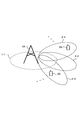
- FIG. 1 is a diagram illustrating an example of a communication system according to the present embodiment.
- the communication system according to the present embodiment includes a base station device 1A and terminal devices 2A and 2B.
- the coverage 1-1 is a range (communication area) in which the base station device 1A can be connected to the terminal device.
- the terminal devices 2A and 2B are also collectively referred to as the terminal device 2.
- the following uplink physical channels are used in uplink radio communication from the terminal apparatus 2A to the base station apparatus 1A.
- the uplink physical channel is used for transmitting information output from an upper layer.
- -PUCCH Physical Uplink Control Channel
- PUSCH Physical Uplink Shared Channel
- PRACH Physical Random Access Channel
- the PUCCH is used for transmitting uplink control information (Uplink Control Information: UCI).
- UCI Uplink Control Information
- the uplink control information includes ACK (a positive acknowledgement) or NACK (a negative acknowledgement) (ACK / NACK) for downlink data (downlink transport block, Downlink-Shared Channel: DL-SCH).
- ACK / NACK for downlink data is also referred to as HARQ-ACK and HARQ feedback.
- the uplink control information includes channel state information (Channel State Information: CSI) for the downlink. Further, the uplink control information includes a scheduling request (Scheduling Request: SR) used to request resources of an uplink shared channel (Uplink-Shared Channel: UL-SCH).
- the channel state information includes a rank index RI (Rank Indicator) designating a suitable spatial multiplexing number, a precoding matrix indicator PMI (Precoding Matrix Indicator) designating a suitable precoder, and a channel quality index CQI designating a suitable transmission rate.
- RI Rank Indicator
- PMI Precoding Matrix Indicator
- CQI channel quality index
- the channel quality indicator CQI (hereinafter referred to as CQI value) is a suitable modulation scheme (for example, QPSK, 16QAM, 64QAM, 256QAM, etc.) and a coding rate in a predetermined band (details will be described later). It can.
- the CQI value can be an index (CQI Index) determined by the change method and coding rate.
- the CQI value can be predetermined by the system.
- the rank index and the precoding quality index can be determined in advance by the system.
- the rank index and the precoding matrix index can be indexes determined by the spatial multiplexing number and precoding matrix information.
- the values of the rank index, the precoding matrix index, and the channel quality index CQI are collectively referred to as CSI values.
- the PUSCH is used for transmitting uplink data (uplink transport block, UL-SCH). Moreover, PUSCH may be used to transmit ACK / NACK and / or channel state information together with uplink data. Moreover, PUSCH may be used in order to transmit only uplink control information.
- PUSCH is used to transmit an RRC message.
- the RRC message is information / signal processed in a radio resource control (Radio-Resource-Control: -RRC) layer.
- the PUSCH is used to transmit a MAC CE (Control Element).
- the MAC CE is information / signal processed (transmitted) in the medium access control (MAC) layer.
- the power headroom may be included in the MAC CE and reported via PUSCH. That is, the MAC CE field may be used to indicate the power headroom level.
- PRACH is used to transmit a random access preamble.
- an uplink reference signal (Uplink Reference Signal: UL SRS) is used as an uplink physical signal.
- the uplink physical signal is not used for transmitting information output from the upper layer, but is used by the physical layer.
- the uplink reference signal includes DMRS (Demodulation Reference Signal) and SRS (Sounding Reference Signal).
- DMRS is related to transmission of PUSCH or PUCCH.
- base station apparatus 1A uses DMRS to perform propagation channel correction for PUSCH or PUCCH.
- SRS is not related to PUSCH or PUCCH transmission.
- the base station apparatus 1A uses SRS to measure the uplink channel state.
- the following downlink physical channels are used in downlink radio communication from the base station apparatus 1A to the terminal apparatus 2A.
- the downlink physical channel is used for transmitting information output from an upper layer.
- PBCH Physical Broadcast Channel
- PCFICH Physical Control Format Indicator Channel
- PHICH Physical Hybrid automatic repeat request Indicator Channel: HARQ instruction channel
- PDCCH Physical Downlink Control Channel
- EPDCCH Enhanced Physical Downlink Control Channel
- PDSCH Physical Downlink Shared Channel
- the PBCH is used to broadcast a master information block (Master Information Block: MIB, Broadcast Channel: BCH) that is commonly used by terminal devices.
- MIB Master Information Block
- BCH Broadcast Channel
- PCFICH is used for transmitting information indicating a region (for example, the number of OFDM symbols) used for transmission of PDCCH.
- PHICH is used to transmit ACK / NACK for uplink data (transport block, codeword) received by the base station apparatus 1A. That is, PHICH is used to transmit a HARQ indicator (HARQ feedback) indicating ACK / NACK for uplink data. ACK / NACK is also referred to as HARQ-ACK.
- the terminal device 2A notifies the received ACK / NACK to the upper layer.
- ACK / NACK is ACK indicating that the data has been correctly received, NACK indicating that the data has not been correctly received, and DTX indicating that there is no corresponding data. Further, when there is no PHICH for the uplink data, the terminal device 2A notifies the upper layer of ACK.
- DCI Downlink Control Information
- a plurality of DCI formats are defined for transmission of downlink control information. That is, fields for downlink control information are defined in the DCI format and mapped to information bits.
- a DCI format 1A used for scheduling one PDSCH (transmission of one downlink transport block) in one cell is defined as a DCI format for the downlink.
- the DCI format for the downlink includes information on PDSCH resource allocation, information on MCS (Modulation & Coding Scheme) for PDSCH, and downlink control information such as a TPC command for PUCCH.
- the DCI format for the downlink is also referred to as a downlink grant (or downlink assignment).
- DCI format 0 used for scheduling one PUSCH (transmission of one uplink transport block) in one cell is defined.
- the DCI format for uplink includes information on PUSCH resource allocation, information on MCS for PUSCH, and uplink control information such as TPC command for PUSCH.
- the DCI format for the uplink is also referred to as uplink grant (or uplink assignment).
- the DCI format for uplink can be used to request downlink channel state information (CSI: “Channel State Information”, also referred to as reception quality information).
- CSI Downlink Channel State Information
- the DCI format for uplink can be used for setting indicating an uplink resource for mapping a channel state information report (CSI feedback report) that the terminal device feeds back to the base station device.
- the channel state information report can be used for setting indicating an uplink resource that periodically reports channel state information (Periodic CSI).
- the channel state information report can be used for mode setting (CSI report mode) for periodically reporting the channel state information.
- the channel state information report can be used for setting indicating an uplink resource for reporting irregular channel state information (Aperiodic CSI).
- the channel state information report can be used for mode setting (CSI report mode) for reporting the channel state information irregularly.
- the base station apparatus can set either the periodic channel state information report or the irregular channel state information report. Further, the base station apparatus can set both the periodic channel state information report and the irregular channel state information report.
- the DCI format for the uplink can be used for setting indicating the type of channel state information report that the terminal apparatus feeds back to the base station apparatus.
- the types of channel state information reports include wideband CSI (for example, Wideband CQI) and narrowband CSI (for example, Subband CQI).
- the terminal apparatus When the PDSCH resource is scheduled using the downlink assignment, the terminal apparatus receives the downlink data on the scheduled PDSCH. In addition, when PUSCH resources are scheduled using an uplink grant, the terminal apparatus transmits uplink data and / or uplink control information using the scheduled PUSCH.
- the PDSCH is used to transmit downlink data (downlink transport block, DL-SCH).
- the PDSCH is used to transmit a system information block type 1 message.
- the system information block type 1 message is cell specific (cell specific) information.
- PDSCH is used to transmit a system information message.
- the system information message includes a system information block X other than the system information block type 1.
- the system information message is cell specific (cell specific) information.
- PDSCH is used to transmit an RRC message.
- the RRC message transmitted from the base station apparatus may be common to a plurality of terminal apparatuses in the cell.
- the RRC message transmitted from the base station device 1A may be a message dedicated to a certain terminal device 2 (also referred to as dedicated signaling). That is, user device specific (user device specific) information is transmitted to a certain terminal device using a dedicated message.
- the PDSCH is used to transmit the MAC CE.
- the RRC message and / or MAC CE is also referred to as higher layer signaling.
- PDSCH can be used to request downlink channel state information.
- the PDSCH can be used to transmit an uplink resource that maps a channel state information report (CSI feedback report) that the terminal device feeds back to the base station device.
- CSI feedback report can be used for setting indicating an uplink resource that periodically reports channel state information (Periodic CSI).
- the channel state information report can be used for mode setting (CSI report mode) for periodically reporting the channel state information.
- the types of downlink channel state information reports include wideband CSI (for example, Wideband CSI) and narrowband CSI (for example, Subband CSI).
- the broadband CSI calculates one channel state information for the system band of the cell.
- the narrowband CSI the system band is divided into predetermined units, and one channel state information is calculated for the division.
- a synchronization signal (Synchronization signal: SS) and a downlink reference signal (Downlink Signal: DL RS) are used as downlink physical signals.
- the downlink physical signal is not used to transmit information output from the upper layer, but is used by the physical layer.
- the synchronization signal is used for the terminal device to synchronize the downlink frequency domain and time domain.
- the downlink reference signal is used by the terminal device for channel correction of the downlink physical channel.
- the downlink reference signal is used by the terminal device to calculate downlink channel state information.
- the downlink reference signal includes CRS (Cell-specific Reference Signal: Cell-specific reference signal), URS related to PDSCH (UE-specific Reference Signal: terminal-specific reference signal, terminal device-specific reference signal), EPDCCH Related DMRS (Demodulation Reference Signal), NZP CSI-RS (Non-Zero Power Chanel State Information Information Reference Signal), and ZP CSI-RS (Zero Power Channel Information State Information Reference Signal) are included.
- CRS Cell-specific Reference Signal: Cell-specific reference signal
- URS related to PDSCH UE-specific Reference Signal: terminal-specific reference signal, terminal device-specific reference signal
- EPDCCH Related DMRS Demodulation Reference Signal
- NZP CSI-RS Non-Zero Power Chanel State Information Information Reference Signal
- ZP CSI-RS Zero Power Channel Information State Information Reference Signal
- CRS is transmitted in the entire band of the subframe, and is used to demodulate PBCH / PDCCH / PHICH / PCFICH / PDSCH.
- the URS associated with the PDSCH is transmitted in subframes and bands used for transmission of the PDSCH associated with the URS, and is used to demodulate the PDSCH associated with the URS.
- DMRS related to EPDCCH is transmitted in subframes and bands used for transmission of EPDCCH related to DMRS.
- DMRS is used to demodulate the EPDCCH with which DMRS is associated.
- NZP CSI-RS resources are set by the base station apparatus 1A.
- the terminal device 2A performs signal measurement (channel measurement) using NZP CSI-RS.
- the resource of ZP CSI-RS is set by the base station apparatus 1A.
- the base station apparatus 1A transmits ZP CSI-RS with zero output.
- the terminal device 2A measures interference in a resource supported by NZP CSI-RS.
- MBSFN Multimedia Broadcast Multicast Service Single Frequency Network
- the MBSFN RS is used for PMCH demodulation.
- PMCH is transmitted through an antenna port used for transmission of MBSFN RS.
- the downlink physical channel and the downlink physical signal are collectively referred to as a downlink signal.
- the uplink physical channel and the uplink physical signal are collectively referred to as an uplink signal.
- the downlink physical channel and the uplink physical channel are collectively referred to as a physical channel.
- the downlink physical signal and the uplink physical signal are collectively referred to as a physical signal.
- BCH, UL-SCH and DL-SCH are transport channels.
- a channel used in the MAC layer is referred to as a transport channel.
- the unit of the transport channel used in the MAC layer is also referred to as a transport block (Transport Block: TB) or a MAC PDU (Protocol Data Unit).
- the transport block is a unit of data that is delivered (delivered) by the MAC layer to the physical layer. In the physical layer, the transport block is mapped to a code word, and an encoding process or the like is performed for each code word.
- a base station device can communicate with a terminal device that supports carrier aggregation (CA: CarriergAggregation) by integrating multiple component carriers (CC: Component Carrier) for wider band transmission.
- CA CarriergAggregation
- CC Component Carrier
- carrier aggregation one primary cell (PCell: Primary Cell) and one or more secondary cells (SCell: Secondary Cell) are set as a set of serving cells.
- a master cell group MCG: Master Cell Group
- a secondary cell group SCG: Secondary Cell Group
- the MCG is composed of a PCell and optionally one or more SCells.
- the SCG includes a primary SCell (PSCell) and optionally one or a plurality of SCells.
- the base station apparatus can communicate using a radio frame.
- a reference signal, a synchronization signal, a discovery signal, a control signal, a data signal, and the like are arranged.
- the radio frame structure includes a frame structure in which a common reference signal or the like in a cell is transmitted discretely in a subframe, a frame structure in which a common reference signal and a data signal are distinguished in terms of area / time .
- the base station apparatus can communicate using, for example, a radio frame structure as shown in FIG. In the area hatched on the upper right in FIG. 2, common reference signals, synchronization signals, discovery signals, control signals, and the like are arranged in cells such as CRS.
- the discovery signal includes part or all of CRS, synchronization signal, and CSI-RS.
- the white area terminal-specific reference signals, data signals, control signals, and the like are arranged.
- the area hatched in the upper right is also referred to as a preamble area and the white area is also referred to as a data area.
- the preamble area and the data area are composed of one or a plurality of symbols.
- symbols included in the preamble area are referred to as preamble symbols
- symbols included in the data area are referred to as data symbols.
- a frame structure in which the preamble area and the data area are separated will be described.
- the present invention is not limited to this, and the arrangement of the signals included in the preamble area and the signals included in the data area is not limited thereto. Regardless, the present invention can be applied.
- FIG. 3 shows an example in which each subframe is changed.
- n is an integer of 1 or more.
- Subframe n in FIG. 3 is allocated more preamble areas than subframe n-1.
- subframe n + 1 in FIG. 3 it is also possible to form a subframe with only a data area without a preamble area.
- the base station apparatus can instruct the terminal apparatus about the range of the preamble area / data area.
- the range of the preamble area / data area can be, for example, the number of symbols included in the preamble area / data area.
- the base station apparatus can instruct the terminal apparatus whether or not there is a preamble area / data area.
- the base station apparatus can periodically set the preamble area. For example, the base station apparatus can transmit a preamble region with a small number of symbols in a short cycle, and can transmit a preamble region with a large number of symbols in a longer cycle.
- FIG. 4 is an example of a communication system using beamforming.
- This communication system includes a base station device 1A and terminal devices 2A and 2B.
- the coverage 1-1 that can cover a wide direction has a short communication distance, and in this example, the terminal devices 2A and 2B are outside the communication area.
- coverages 2-1 to 2-3 are coverages when beamforming is used, and each coverage has a different beam pattern. When beam forming is used, only a narrow direction can be covered, but the communication distance becomes long.
- the terminal device 2A is inside the coverage 2-1
- the terminal device 2B is inside the coverage 2-3
- the base station device 1A and the terminal devices 2A and 2B can be connected.
- the base station device 1A and the terminal devices 2A and 2B need to search which beam pattern is used in the communication area at the time of initial connection.
- a communication area using beam forming is also referred to as a beam cell or a beam area.
- a beam connected to a terminal device (establishing a radio link) is called a serving beam.
- the terminal apparatus uses a preamble signal to synchronize time / frequency and detect a cell search (cell search) and / or a beam identifier (beam ID, beam cell ID) to detect a physical cell identifier (PCID, cell ID). Search (beam search) is performed.
- the cell ID may include a beam ID.
- a cell ID that includes a beam ID is also referred to as an extended cell ID.
- the base station apparatus can perform beam forming and transmitting a part or all of the signal included in the preamble.
- the preamble signal / discovery signal may include one or a plurality of signals subjected to beam forming.
- the preamble signal may include one or more synchronization signals / CRS / discovery signals that have been beamformed.
- the discovery signal may include one or more synchronization signals / CRS / CSI-RS that have been beamformed.
- the base station apparatus can change the beam pattern for each preamble region or each preamble symbol.
- the beam pattern may include a pattern that is not beam-formed.
- the base station device transmits a synchronization signal that can identify the base station device and the beam pattern.
- the terminal device can know the cell ID and the beam ID from the synchronization signal sequence.
- the base station apparatus changes the beam pattern based on radio resources such as slots and subframes in which the synchronization signal is arranged, the synchronization signal is generated based on the cell ID and information on the radio resource.
- the radio resource information is, for example, a slot / subframe number and a subband number.
- the base station apparatus can multiplex (add, superimpose) the preamble signal / synchronization signal / discovery signal beam-formed with different beam patterns and arrange and transmit it in one preamble area or preamble symbol.
- the base station apparatus multiplexes (adds and superimposes) the preamble signal / synchronization signal / discovery signal generated based on different beam IDs, arranges them in one preamble region or preamble symbol, and transmits them. Can do.
- the terminal device can know the cell ID and / or the beam ID from the preamble signal / synchronization signal / discovery signal with good communication quality.
- the synchronization signal may be one type or multiple types.
- PSS Primary Synchronization Signal, first synchronization signal
- SSS SecondaryPSSynchronization Signal, second synchronization signal
- PSS and SSS are used.
- the cell ID and / or beam ID are used.
- the function may be divided for each type.
- the cell ID can be identified by PSS
- the beam ID can be identified by SSS.
- the cell ID can be identified by PSS and SSS
- the beam ID can be identified by another synchronization signal (third synchronization signal).
- a suitable beam in the base station apparatus can be selected by beam search at the time of initial connection. At this time, it is desirable to perform a beam search even in the terminal device.
- the beam in the terminal device can be used as a reception beam or an uplink transmission beam in the terminal device. It is desirable that the beam search in the terminal device be different synchronization signal sequences that have been subjected to the same beam forming. Therefore, the base station apparatus arranges and transmits different series of synchronization signals beamformed with the same beam pattern in the preamble area.
- the synchronization signal that can be used for beam search in the terminal apparatus may be arranged in one subframe or may be arranged in a plurality of subframes.
- the plurality of synchronization signals arranged in the preamble area by the base station apparatus may simultaneously include a synchronization signal based on different synchronization signal sequences formed with the same beamforming and different synchronization signal sequences formed with different beamforming.
- the base station apparatus may notify the terminal apparatus of information indicating which one of the plurality of synchronization signals arranged in the preamble region is the same beamformed synchronization signal or a different beamformed synchronization signal. it can. That is, the base station apparatus can continuously transmit a synchronization signal associated with the beam search of the base station apparatus and a synchronization signal associated with the beam search of the terminal apparatus described later to the preamble region. .
- the terminal device can search for the beam of the terminal device when performing a beam search of the base station device. Further, the terminal device can search for the beam of the terminal device when instructed by the base station device. Further, the terminal device can periodically search for the beam of the terminal device. The beam search period of the terminal device is instructed from the base station device.
- the base station apparatus transmits a measurement setting, which is setting information for clarifying the measurement performed by the terminal device, to the terminal device.
- the measurement settings include some or all of the measurement object list, report setting list, measurement ID list, and other parameters.
- the measurement object is information related to cell information and includes carrier frequency, measurement bandwidth, antenna port, cell list for reporting measurement results, black cell list composed of cells not reporting measurement results, measurement DS settings, and measurement.
- a beam list that reports results and a part or all of a black beam list that does not report measurement results are included.
- the cell reporting the measurement result includes a cell index, a physical cell ID, and a cell individual offset as parameters.
- the beam reporting the measurement result includes a beam ID and a part or all of the physical cell ID.
- the report setting includes a trigger type indicating whether the report is a regular report or an event report.
- the event ID is included in the report setting.
- the event ID includes, for example, the following, and a threshold necessary for calculating the condition (threshold 1 and threshold 2 if necessary) and an offset value are also set.
- Event A1 When the measurement result of the serving cell is better than the set threshold value
- Event A2 When the measurement result of the serving cell is worse than the set threshold value
- Event A3 The measurement result of the neighboring cell is PCell / PSCell measurement When the offset value is better than the set offset value
- Event A4 When the measurement result of the adjacent cell is better than the set threshold value
- Event A5 PCell / PSCell measurement result is higher than the set threshold value 1
- Event A6 When the measurement result of the adjacent cell becomes better than the set offset value than the measurement result of the SCell
- Event C1 CSI -When the measurement result of the RS resource becomes better than the set threshold, event C2 When the measurement result with the reference CSI-RS resource in which the measurement result with the CSI-RS resource is set becomes better than the offset
- Event D1 When the measurement result with the serving beam becomes better than the set threshold
- Event D2 When the measurement result of the serving beam becomes worse than the set threshold value
- Event D3 When the
- the events C1 and C2 are selected when the measurement DS setting is set in the measurement object.
- the measurement DS setting is information applicable to the measurement by the discovery signal, and includes the discovery signal measurement timing setting period and offset, the period of the detection signal occasion, and the measurement CSI-RS list.
- the measurement CSI-RS is set by the measurement CSI-RS ID, the physical cell ID, the scrambling identity for generating the pseudo-random sequence, the resource setting which is the CSI-RS setting, and the SSS and CSI- in the discovery signal. RS subframe offset and CSI-RS individual offset are included. Further, the CSI-RS for measurement is arranged in the preamble area and / or the data area.
- the terminal device reports the serving cell, serving beam, cell list, beam list, detected cell, or measurement result of the detected beam to the base station device.
- the terminal device reports the measurement result periodically or when an event occurs according to an instruction from the base station device.
- the measurement results that the terminal device reports to the base station device are: measurement ID, PCell measurement result, neighbor cell measurement result list, serving frequency measurement result, CSI-RS measurement result list, PCell beam measurement result, SCell Includes a part or all of a measurement result list of beams and a measurement result list of beams (adjacent beams) other than the serving beam.
- the measurement result of PCell includes RSRP (Reference Signal Received Power) and RSRQ (Reference Signal Received Quality).
- RSRP is received power calculated using CRS.
- RSRQ is obtained from the ratio of RSRP and received signal strength (RSSI: “Received” Signal “Strength” Indicator).
- the measurement result of the neighbor cell includes a part or all of the physical cell ID, RSRP, and RSRQ.
- the measurement result list of the serving frequency includes a serving cell index for specifying a serving cell, a measurement result of SCell, and a measurement result of a neighboring cell with the best measurement result.
- the measurement result of the SCell and the measurement result of the neighboring cell with the best measurement result include RSRP and RSRQ.
- the measurement result of CSI-RS includes part or all of the ID of CSI-RS for measurement, CSI-RSRP, and CSI-RSRQ.
- CSI-RSRP is received power calculated using CSI-RS.
- CSI-RSRQ is obtained from the ratio of CSI-RSRP and RSSI.
- the measurement result of the beam in the PCell includes a part or all of the physical cell ID, beam ID, RSRP, and RSRQ.
- the measurement result of the beam in the SCell includes a part or all of the physical cell ID, beam ID, RSRP, and RSRQ.
- the measurement results of beams other than the serving beam include some or all of the physical cell ID, beam ID, RSRP, and RSRQ.
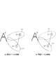
- FIG. 5 shows an example of a fixed beam and a variable beam.
- the communication system of FIG. 5 includes a base station device 1A and a terminal device 2A.
- Beam areas 2-1 and 2-2 are communication areas having different beam IDs.
- the base station apparatus 1A changes the beam ID of the terminal apparatus 2A to the beam ID of the beam area 2-2. Switch.
- the base station apparatus 1A transmits a new beam ID to the terminal apparatus 2A.
- the terminal device 2A performs synchronization, RRM measurement, CSI measurement / report, data demodulation, and the like using the beam ID received from the base station device 1A.
- the terminal device 2A In the case of a variable beam, it is assumed that the terminal device 2A has moved in the direction of the arrow as shown in FIG.
- the base station apparatus 1A changes the beam pattern without changing the beam ID of the terminal apparatus 2A.
- the terminal device 2A can communicate without knowing that the beam pattern has changed.
- the base station apparatus 1A can know a suitable beam pattern of the terminal apparatus 2A by receiving a report regarding a suitable beam pattern from the terminal apparatus 2A.
- the base station apparatus 1A and the terminal apparatus 2A can change the frequency band for communication. For example, when the communication quality between the base station apparatus 1A and the terminal apparatus 2A that perform communication in a frequency band of 6 GHz or more rapidly decreases, the base station apparatus 1A and the terminal apparatus 2A have a communication frequency in a frequency band of 6 GHz or less. Can be switched.
- the base station apparatus 1A and the terminal apparatus 2A again The communication frequency can be switched to the frequency band.
- the base station apparatus 1A and the terminal apparatus 2A can continue to use the beam forming used by each before switching.
- the base station device 1A and the terminal device 2A may perform a beam search again when switching the communication frequency to the frequency band before switching, or after performing a beam search again in the frequency band before switching, The communication frequency may be switched.
- the switchable frequency band combinations may be determined in advance.
- switchable frequency band combinations can be linked to carrier aggregation or dual connectivity. The combination of the frequency bands depends on the function (UE ⁇ Capability) of the terminal device.
- the base station device 1A can switch to a frequency band indicated by a combination of frequency bands included in the function of the terminal device received from the terminal device 2A.
- each terminal device may receive the interference between beams.
- the base station apparatus can perform transmission by dividing time / frequency / space resources.
- the base station apparatus can transmit the antenna ports separately among the terminal apparatuses.
- the same antenna port is allocated between terminal devices, but transmission can be performed with different beam patterns for each terminal device.
- the terminal apparatus supports a function for removing or suppressing inter-beam interference
- the base station apparatus assists the terminal apparatus for removing or suppressing inter-beam interference (adjacent beam interference) (adjacent beam information). Can be sent.
- the terminal device can remove or suppress inter-beam interference using the received assist information.
- Assist information physical cell ID, the beam ID, CRS number of ports, P A list, P B, MBSFN (Multimedia Broadcast multicast service Single Frequency Network) subframe configuration, transmission mode list, the resource allocation granularity, TDD of UL / DL sub It includes part or all of the frame configuration, ZP / NZP CSI-RS configuration, and QCL (quasi co-location) information.
- P A is the PDSCH and CRS power ratio in OFDM symbols CRS is not arranged (power offset).
- the QCL information is information related to the QCL for a predetermined antenna port, a predetermined signal, or a predetermined channel.
- a predetermined antenna port if the long-term characteristics of the channel carrying the symbol on one antenna port can be inferred from the channel carrying the symbol on the other antenna port, those antenna ports are QCL It is called.
- Long interval characteristics include delay spread, Doppler spread, Doppler shift, average gain and / or average delay. That is, when the two antenna ports are QCL, the terminal device can be regarded as having the same long section characteristics at the antenna ports.
- each parameter included in the assist information may be set to one value (candidate) or a plurality of values (candidates).
- the terminal device interprets that the parameter indicates a value that may be set by the base station device that causes interference, and sets the interference signal from the multiple values. Detect (specify) the parameters that are being used.
- the assist information may indicate information of another base station apparatus / beam, or may indicate information of its own base station apparatus / beam.
- the assist information may be used when performing various measurements.
- the measurement includes RRM (Radio Resource Management) measurement, RLM (Radio Link Monitoring) measurement, and CSI (Channel State Information) measurement.
- the base station apparatus can further perform terminal-specific beam forming on the beam area with respect to the terminal apparatus.
- the base station apparatus can perform precoding based on a code book or PMI, or can perform beam forming unique to the base station apparatus.
- the base station apparatus can know a suitable CSI from the CSI report from the terminal apparatus.
- the CSI reported by the terminal device includes CQI / PMI / RI / CRI.
- the base station apparatus can know a suitable beam pattern of the terminal apparatus from the CSI calculated from the CSI-RS.
- the CSI-RS can transmit (set) non-preformed CSI-RS (non-precoded CSI-RS) and / or beamformed CSI-RS (beamformed CSI-RS).
- the CSI-RS is arranged in the preamble area and / or the data area.
- the base station apparatus can include non-precoded CSI-RS information or beamformed CSI-RS information in the CSI-RS setting information.
- Non-precoded CSI-RS information includes information on codebook subset restrictions (CBSR: Codebook Subset Restriction), information on codebooks, and interference measurement restriction settings that determine whether to restrict resources when measuring interference. Includes some or all.
- Beamformed CSI-RS information includes an ID list for CSI-RS settings, an ID list for CSI-IM (CSI-Interference Measurement) settings, information on codebook subset restrictions, and whether to limit resources when measuring channels Including some or all of the channel measurement restrictions.
- the ID list of the CSI-IM setting is composed of one or a plurality of CSI-IM setting ID information, and the CSI-IM setting ID information includes a CSI-IM setting ID and a part or all of interference measurement restrictions. CSI-IM is also used for interference measurement.
- the base station apparatus may include a setting (CSI process) related to a procedure for calculating channel state information by associating at least CSI-RS for channel measurement with CSI-IM for interference measurement in higher layer signaling. It can.
- the CSI process can include a part or all of the CSI process ID, non-precoded CSI-RS information, and beamformed CSI-RS information.
- the base station apparatus can set one or more CSI processes.
- the base station apparatus can generate CSI feedback independently for each CSI process.
- the base station apparatus can set the CSI-RS resource and the CSI-IM differently for each CSI process.
- one or more CSI processes are set, and CSI reporting is performed independently for each set CSI process.
- the CSI process is set in a predetermined transmission mode.
- the beam ID and beam forming can be set for each cell.
- the beam ID and beam forming may be set by PCell and SCell, or may be set only by PCell or only SCell.
- CA or DC it is possible to CA or DC a radio frame that can set beam ID and beam forming and a radio frame that cannot set beam ID and beam forming.
- a radio frame that can set beam ID and beam forming is set to PCell / SCell, and a radio frame that cannot set beam ID and beam forming is set to PSCell / SCell.
- a radio frame in which beam ID and beam forming cannot be set is set in PCell / SCell, and a radio frame in which beam ID and beam forming can be set is set in PSCell / SCell.
- the base station apparatus and the terminal apparatus can set the beam forming set in one CC (cell) to another CC.
- the base station apparatus and the terminal apparatus can perform a beam search only with a predetermined CC (for example, a CC set in PCell / SCell).
- the base station apparatus and the terminal apparatus can set CC conditions that allow the same beamforming to be set. For example, the base station apparatus and the terminal apparatus can set the same beam forming between CCs whose difference in center frequency is lower than a predetermined value. Alternatively, the base station apparatus and the terminal apparatus can set the same beam forming within the same frequency band (Intra-band).
- the antenna gain in the maximum radiation direction can be determined according to the transmission power (antenna power) in each device. For example, when the antenna power exceeds 10 dBm, the base station device and the terminal device can set the antenna gain in the maximum radiation direction of the beam pattern to 10 dBi or more.
- the antenna gain in the maximum radiation direction can be determined according to the type of frequency band transmitted by each apparatus. For example, when the frequency band transmitted by each device is a so-called licensed band obtained from a country or region where the wireless service provider provides a service (license), The antenna gain in the maximum radiation direction can be set to a different value depending on a frequency band called a so-called unlicensed band that does not require use permission (license) from the country or region.
- a so-called licensed band obtained from a country or region where the wireless service provider provides a service (license)
- the antenna gain in the maximum radiation direction can be set to a different value depending on a frequency band called a so-called unlicensed band that does not require use permission (license) from the country or region.
- the base station apparatus can switch between transmitting a beamformed preamble signal / synchronization signal / discovery signal or transmitting a preamble signal / synchronization signal / discovery signal that is not beamformed depending on the frequency band. That is, the terminal device can determine whether to perform initial connection (detection of beam ID) assuming beamforming or initial connection not assuming beamforming, depending on the frequency band.
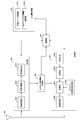
- FIG. 6 is a schematic block diagram showing the configuration of the base station apparatus 1A in the present embodiment.
- the base station apparatus 1 ⁇ / b> A performs transmission / reception with an upper layer processing unit (upper layer processing step) 101, a control unit (control step) 102, a transmission unit (transmission step) 103, and a reception unit (reception step) 104.
- An antenna 105 is included.
- the upper layer processing unit 101 includes a radio resource control unit (radio resource control step) 1011 and a scheduling unit (scheduling step) 1012.
- the transmission unit 103 includes an encoding unit (encoding step) 1031, a modulation unit (modulation step) 1032, a downlink reference signal generation unit (downlink reference signal generation step) 1033, a multiplexing unit (multiplexing step) 1034, a radio A transmission unit (wireless transmission step) 1035 is included.
- the reception unit 104 includes a wireless reception unit (wireless reception step) 1041, a demultiplexing unit (demultiplexing step) 1042, a demodulation unit (demodulation step) 1043, and a decoding unit (decoding step) 1044.
- the upper layer processing unit 101 includes a medium access control (Medium Access Control: MAC) layer, a packet data integration protocol (Packet Data Convergence Protocol: PDCP) layer, a radio link control (Radio Link Control: RLC) layer, a radio resource control (Radio) Resource (Control: RRC) layer processing.
- MAC Medium Access Control
- PDCP Packet Data Convergence Protocol
- RLC Radio Link Control
- RRC radio resource control
- upper layer processing section 101 generates information necessary for controlling transmission section 103 and reception section 104 and outputs the information to control section 102.
- the upper layer processing unit 101 receives information related to the terminal device such as the function (UE capability) of the terminal device from the terminal device. In other words, the terminal apparatus transmits its own function to the base station apparatus using an upper layer signal.
- information on a terminal device includes information indicating whether the terminal device supports a predetermined function, or information indicating that the terminal device has introduced a predetermined function and has completed a test.
- whether or not to support a predetermined function includes whether or not installation and testing for the predetermined function have been completed.
- the terminal device transmits information (parameters) indicating whether the predetermined function is supported.
- the terminal device does not transmit information (parameter) indicating whether or not the predetermined device is supported. That is, whether or not to support the predetermined function is notified by whether or not information (parameter) indicating whether or not to support the predetermined function is transmitted. Note that information (parameter) indicating whether or not to support a predetermined function may be notified using 1 bit of 1 or 0.
- the radio resource control unit 1011 generates or obtains downlink data (transport block), system information, RRC message, MAC CE, and the like arranged on the downlink PDSCH from an upper node.
- the radio resource control unit 1011 outputs downlink data to the transmission unit 103 and outputs other information to the control unit 102.
- the radio resource control unit 1011 manages various setting information of the terminal device.
- the scheduling unit 1012 determines the frequency and subframe to which the physical channels (PDSCH and PUSCH) are allocated, the coding rate and modulation scheme (or MCS) of the physical channels (PDSCH and PUSCH), transmission power, and the like.
- the scheduling unit 1012 outputs the determined information to the control unit 102.
- the scheduling unit 1012 generates information used for physical channel (PDSCH and PUSCH) scheduling based on the scheduling result.
- the scheduling unit 1012 outputs the generated information to the control unit 102.
- the control unit 102 generates a control signal for controlling the transmission unit 103 and the reception unit 104 based on the information input from the higher layer processing unit 101.
- the control unit 102 generates downlink control information based on the information input from the higher layer processing unit 101 and outputs the downlink control information to the transmission unit 103.
- the transmission unit 103 generates a downlink reference signal according to the control signal input from the control unit 102, and encodes the HARQ indicator, downlink control information, and downlink data input from the higher layer processing unit 101. Then, PHICH, PDCCH, EPDCCH, PDSCH, and downlink reference signal are multiplexed, and the signal is transmitted to the terminal apparatus 2 via the transmission / reception antenna 105.
- the encoding unit 1031 uses a predetermined encoding method such as block encoding, convolutional encoding, and turbo encoding for the HARQ indicator, downlink control information, and downlink data input from the higher layer processing unit 101. Encoding is performed using the encoding method determined by the radio resource control unit 1011.
- the modulation unit 1032 converts the encoded bits input from the encoding unit 1031 into BPSK (Binary Phase Shift Shift Keying), QPSK (quadrature Phase Shift Shift Keying), 16 QAM (quadrature Amplitude Modulation), 64 QAM, 256 QAM, and the like. Or it modulates with the modulation system which the radio
- the downlink reference signal generation unit 1033 refers to a sequence known by the terminal apparatus 2A, which is obtained based on a predetermined rule based on a physical cell identifier (PCI, cell ID) for identifying the base station apparatus 1A. Generate as a signal.
- PCI physical cell identifier
- the multiplexing unit 1034 multiplexes the modulated modulation symbol of each channel, the generated downlink reference signal, and downlink control information. That is, multiplexing section 1034 arranges the modulated modulation symbol of each channel, the generated downlink reference signal, and downlink control information in the resource element.
- the wireless transmission unit 1035 generates an OFDM symbol by performing inverse fast Fourier transform (Inverse Fast Transform: IFFT) on the multiplexed modulation symbol and the like, and adds a cyclic prefix (cyclic prefix: CP) to the OFDM symbol.
- IFFT inverse fast Fourier transform
- CP cyclic prefix
- the receiving unit 104 separates, demodulates, and decodes the received signal received from the terminal device 2A via the transmission / reception antenna 105 in accordance with the control signal input from the control unit 102, and outputs the decoded information to the upper layer processing unit 101. .
- the radio reception unit 1041 converts an uplink signal received via the transmission / reception antenna 105 into a baseband signal by down-conversion, removes unnecessary frequency components, and amplifies the signal level so that the signal level is properly maintained.
- the level is controlled, quadrature demodulation is performed based on the in-phase component and the quadrature component of the received signal, and the analog signal that has been demodulated is converted into a digital signal.
- the wireless reception unit 1041 removes a portion corresponding to the CP from the converted digital signal.
- Radio receiving section 1041 performs fast Fourier transform (FFT) on the signal from which CP has been removed, extracts a signal in the frequency domain, and outputs the signal to demultiplexing section 1042.
- FFT fast Fourier transform
- the demultiplexing unit 1042 demultiplexes the signal input from the wireless reception unit 1041 into signals such as PUCCH, PUSCH, and uplink reference signal. This separation is performed based on radio resource allocation information included in the uplink grant that is determined in advance by the radio resource control unit 1011 by the base station apparatus 1A and notified to each terminal apparatus 2.
- the demultiplexing unit 1042 compensates for the propagation paths of the PUCCH and PUSCH. Further, the demultiplexing unit 1042 demultiplexes the uplink reference signal.
- the demodulator 1043 performs inverse discrete Fourier transform (Inverse Discrete Fourier Transform: IDFT) on the PUSCH to obtain modulation symbols, and for each of the PUCCH and PUSCH modulation symbols, BPSK, QPSK, 16QAM, 64QAM, 256QAM, etc.
- IDFT inverse discrete Fourier transform
- the received signal is demodulated by using a modulation method determined or notified in advance by the own device to each of the terminal devices 2 using an uplink grant.
- the decoding unit 1044 uses the coding rate of the demodulated PUCCH and PUSCH in a predetermined encoding method, the predetermined coding method, or the coding rate notified by the own device to the terminal device 2 using the uplink grant. Decoding is performed, and the decoded uplink data and uplink control information are output to the upper layer processing section 101. When PUSCH is retransmitted, decoding section 1044 performs decoding using the coded bits held in the HARQ buffer input from higher layer processing section 101 and the demodulated coded bits.
- FIG. 7 is a schematic block diagram showing the configuration of the terminal device 2 in the present embodiment.
- the terminal device 2A includes an upper layer processing unit (upper layer processing step) 201, a control unit (control step) 202, a transmission unit (transmission step) 203, a reception unit (reception step) 204, a channel state An information generation unit (channel state information generation step) 205 and a transmission / reception antenna 206 are included.
- the upper layer processing unit 201 includes a radio resource control unit (radio resource control step) 2011 and a scheduling information interpretation unit (scheduling information interpretation step) 2012.
- the transmission unit 203 includes an encoding unit (encoding step) 2031, a modulation unit (modulation step) 2032, an uplink reference signal generation unit (uplink reference signal generation step) 2033, a multiplexing unit (multiplexing step) 2034, and a radio A transmission unit (wireless transmission step) 2035 is included.
- the reception unit 204 includes a wireless reception unit (wireless reception step) 2041, a demultiplexing unit (demultiplexing step) 2042, and a signal detection unit (signal detection step) 2043.
- the upper layer processing unit 201 outputs uplink data (transport block) generated by a user operation or the like to the transmission unit 203. Further, the upper layer processing unit 201 includes a medium access control (Medium Access Control: MAC) layer, a packet data integration protocol (Packet Data Convergence Protocol: PDCP) layer, a radio link control (Radio Link Control: RLC) layer, and a radio resource control. Process the (Radio Resource Control: RRC) layer.
- Medium Access Control Medium Access Control: MAC
- PDCP Packet Data Convergence Protocol
- RLC Radio Link Control
- RRC Radio Resource Control
- the upper layer processing unit 201 outputs information indicating the function of the terminal device supported by the own terminal device to the transmission unit 203.
- the radio resource control unit 2011 manages various setting information of the own terminal device. Also, the radio resource control unit 2011 generates information arranged in each uplink channel and outputs the information to the transmission unit 203.
- the radio resource control unit 2011 acquires setting information regarding CSI feedback transmitted from the base station apparatus, and outputs the setting information to the control unit 202.
- the scheduling information interpretation unit 2012 interprets the downlink control information received via the reception unit 204 and determines scheduling information.
- the scheduling information interpretation unit 2012 generates control information for controlling the reception unit 204 and the transmission unit 203 based on the scheduling information, and outputs the control information to the control unit 202.
- the control unit 202 generates a control signal for controlling the receiving unit 204, the channel state information generating unit 205, and the transmitting unit 203 based on the information input from the higher layer processing unit 201.
- the control unit 202 controls the reception unit 204 and the transmission unit 203 by outputting the generated control signal to the reception unit 204, the channel state information generation unit 205, and the transmission unit 203.
- the control unit 202 controls the transmission unit 203 to transmit the CSI generated by the channel state information generation unit 205 to the base station apparatus.
- the receiving unit 204 separates, demodulates, and decodes the received signal received from the base station apparatus 1A via the transmission / reception antenna 206 according to the control signal input from the control unit 202, and sends the decoded information to the upper layer processing unit 201. Output.
- the radio reception unit 2041 converts a downlink signal received via the transmission / reception antenna 206 into a baseband signal by down-conversion, removes unnecessary frequency components, and increases the amplification level so that the signal level is appropriately maintained. , And quadrature demodulation based on the in-phase and quadrature components of the received signal, and converting the quadrature demodulated analog signal into a digital signal.
- the wireless reception unit 2041 removes a portion corresponding to CP from the converted digital signal, performs fast Fourier transform on the signal from which CP is removed, and extracts a frequency domain signal.
- the demultiplexing unit 2042 separates the extracted signal into PHICH, PDCCH, EPDCCH, PDSCH, and downlink reference signal. Further, the demultiplexing unit 2042 performs channel compensation of PHICH, PDCCH, and EPDCCH based on the channel estimation value of the desired signal obtained from the channel measurement, detects downlink control information, and Output. In addition, control unit 202 outputs PDSCH and the channel estimation value of the desired signal to signal detection unit 2043.
- the signal detection unit 2043 detects a signal using the PDSCH and the channel estimation value, and outputs the signal to the higher layer processing unit 201.
- the transmission unit 203 generates an uplink reference signal according to the control signal input from the control unit 202, encodes and modulates the uplink data (transport block) input from the higher layer processing unit 201, PUCCH, The PUSCH and the generated uplink reference signal are multiplexed and transmitted to the base station apparatus 1A via the transmission / reception antenna 206.
- the encoding unit 2031 performs encoding such as convolutional encoding and block encoding on the uplink control information input from the higher layer processing unit 201. Also, the coding unit 2031 performs turbo coding based on information used for PUSCH scheduling.
- the modulation unit 2032 modulates the coded bits input from the coding unit 2031 using a modulation scheme notified by downlink control information such as BPSK, QPSK, 16QAM, 64QAM, or a modulation scheme predetermined for each channel. .
- the uplink reference signal generation unit 2033 includes a physical cell identifier (physical cell identity: referred to as PCI, Cell ID, etc.) for identifying the base station apparatus 1A, a bandwidth for arranging the uplink reference signal, and an uplink grant.
- a sequence determined by a predetermined rule is generated on the basis of the cyclic shift, the parameter value for the generation of the DMRS sequence, and the like notified in (1).
- the multiplexing unit 2034 rearranges the PUSCH modulation symbols in parallel according to the control signal input from the control unit 202, and then performs a discrete Fourier transform (DFT). Also, the multiplexing unit 2034 multiplexes the PUCCH and PUSCH signals and the generated uplink reference signal for each transmission antenna port. That is, multiplexing section 2034 arranges the PUCCH and PUSCH signals and the generated uplink reference signal in the resource element for each transmission antenna port.
- DFT discrete Fourier transform
- the wireless transmission unit 2035 performs inverse fast Fourier transform (Inverse Fast Transform: IFFT) on the multiplexed signal, performs SC-FDMA modulation, generates SC-FDMA symbols, and generates the generated SC-FDMA symbols.
- IFFT inverse fast Fourier transform
- CP is added to baseband digital signal, baseband digital signal is converted to analog signal, excess frequency component is removed, converted to carrier frequency by up-conversion, power amplification, transmission / reception antenna It outputs to 206 and transmits.
- the program that operates in the apparatus related to the present invention may be a program that controls the central processing unit (CPU) or the like to function the computer so as to realize the functions of the above-described embodiments related to the present invention.
- the program or information handled by the program is temporarily read into volatile memory such as Random Access Memory (RAM) during processing, or stored in non-volatile memory such as flash memory or Hard Disk Drive (HDD).
- volatile memory such as Random Access Memory (RAM) during processing
- non-volatile memory such as flash memory or Hard Disk Drive (HDD).
- HDD Hard Disk Drive
- a program for realizing the functions of the embodiments may be recorded on a computer-readable recording medium.
- the “computer system” here is a computer system built in the apparatus, and includes hardware such as an operating system and peripheral devices.
- the “computer-readable recording medium” may be any of a semiconductor recording medium, an optical recording medium, a magnetic recording medium, and the like.
- Computer-readable recording medium means a program that dynamically holds a program for a short time, such as a communication line when transmitting a program via a network such as the Internet or a communication line such as a telephone line.
- a volatile memory inside a computer system serving as a server or a client may be included, which holds a program for a certain period of time.
- the program may be a program for realizing a part of the functions described above, and may be a program capable of realizing the functions described above in combination with a program already recorded in a computer system.
- each functional block or various features of the apparatus used in the above-described embodiments can be implemented or executed by an electric circuit, that is, typically an integrated circuit or a plurality of integrated circuits.
- Electrical circuits designed to perform the functions described herein can be general purpose processors, digital signal processors (DSPs), application specific integrated circuits (ASICs), field programmable gate arrays (FPGAs), or other Programmable logic devices, discrete gate or transistor logic, discrete hardware components, or combinations thereof.
- a general purpose processor may be a microprocessor or a conventional processor, controller, microcontroller, or state machine.
- the electric circuit described above may be configured with a digital circuit or an analog circuit.
- an integrated circuit based on the technology can be used.
- the present invention is not limited to the above-described embodiment.
- an example of the apparatus has been described.
- the present invention is not limited to this, and a stationary or non-movable electronic device installed indoors or outdoors, such as an AV device, a kitchen device, It can be applied to terminal devices or communication devices such as cleaning / washing equipment, air conditioning equipment, office equipment, vending machines, and other daily life equipment.
- the present invention is suitable for use in a base station device, a terminal device, and a communication method.
- Base station apparatus 2A, 2B Terminal apparatus 101 Upper layer processing section 102 Control section 103 Transmission section 104 Reception section 105 Transmission / reception antenna 1011 Radio resource control section 1012 Scheduling section 1031 Encoding section 1032 Modulation section 1033 Downlink reference signal generation section 1034 Multiplexing Unit 1035 radio transmission unit 1041 radio reception unit 1042 demultiplexing unit 1043 demodulation unit 1044 decoding unit 201 upper layer processing unit 202 control unit 203 transmission unit 204 reception unit 205 channel state information generation unit 206 transmission / reception antenna 2011 radio resource control unit 2012 scheduling information Interpreter 2031 Encoder 2032 Modulator 2033 Uplink reference signal generator 2034 Multiplexer 2035 Radio transmitter 2041 Radio receiver 2042 Demultiplexer 2043 Signal detector
Landscapes
- Engineering & Computer Science (AREA)
- Signal Processing (AREA)
- Computer Networks & Wireless Communication (AREA)
- Quality & Reliability (AREA)
- Physics & Mathematics (AREA)
- Electromagnetism (AREA)
- Mobile Radio Communication Systems (AREA)
- Radio Transmission System (AREA)
Abstract
La présente invention concerne un dispositif de station de base, un dispositif terminal et un procédé de communication qui permettent d'améliorer le débit lors de la formation de faisceaux. Le dispositif de station de base comprend une unité de transmission, qui transmet une configuration de mesure qui consiste en des informations de configuration pour des mesures réalisées par un dispositif terminal, et une unité de réception qui reçoit un rapport de mesure du dispositif terminal. La configuration de mesure comprend une configuration de rapport et une liste de faisceaux de mesure, la configuration de rapport incluant un réglage pour un établissement périodique de rapports ou pour un établissement d'un rapport sur la base d'un événement, et les faisceaux de mesure comprenant un identifiant de cellule et un identifiant de faisceau.
Priority Applications (1)
| Application Number | Priority Date | Filing Date | Title |
|---|---|---|---|
| US16/071,227 US20210051502A1 (en) | 2016-01-26 | 2017-01-24 | Base station apparatus, terminal apparatus, and communication method |
Applications Claiming Priority (2)
| Application Number | Priority Date | Filing Date | Title |
|---|---|---|---|
| JP2016012181A JP2019054305A (ja) | 2016-01-26 | 2016-01-26 | 基地局装置、端末装置および通信方法 |
| JP2016-012181 | 2016-01-26 |
Publications (2)
| Publication Number | Publication Date |
|---|---|
| WO2017130967A2 true WO2017130967A2 (fr) | 2017-08-03 |
| WO2017130967A3 WO2017130967A3 (fr) | 2017-09-28 |
Family
ID=59398274
Family Applications (1)
| Application Number | Title | Priority Date | Filing Date |
|---|---|---|---|
| PCT/JP2017/002360 WO2017130967A2 (fr) | 2016-01-26 | 2017-01-24 | Dispositif de station de base, dispositif terminal et procédé de communication |
Country Status (3)
| Country | Link |
|---|---|
| US (1) | US20210051502A1 (fr) |
| JP (1) | JP2019054305A (fr) |
| WO (1) | WO2017130967A2 (fr) |
Cited By (4)
| Publication number | Priority date | Publication date | Assignee | Title |
|---|---|---|---|---|
| WO2019049347A1 (fr) * | 2017-09-08 | 2019-03-14 | 株式会社Nttドコモ | Terminal utilisateur et procédé de communication sans fil |
| JP2019057911A (ja) * | 2017-09-20 | 2019-04-11 | 華碩電腦股▲ふん▼有限公司 | 無線通信システムにおけるビーム決定の方法及び装置 |
| JP2021503230A (ja) * | 2017-11-14 | 2021-02-04 | 鴻穎創新有限公司Fg Innovation Company Limited | 複数のコンポーネントキャリアを用いたネットワークアシスト伝送のための方法、デバイスおよびシステム |
| EP3917194A4 (fr) * | 2019-01-25 | 2022-03-16 | Datang Mobile Communications Equipment Co., Ltd. | Procédé de rapport d'informations et procédé de réception, appareil et dispositif |
Families Citing this family (9)
| Publication number | Priority date | Publication date | Assignee | Title |
|---|---|---|---|---|
| KR102489996B1 (ko) * | 2017-03-22 | 2023-01-18 | 삼성전자 주식회사 | 랜덤 액세스(rach) 절차 동안 초기 빔 정렬을 수행하는 방법 및 사용자 장치 |
| CN109150445B (zh) * | 2017-06-16 | 2021-08-24 | 大唐移动通信设备有限公司 | 一种下行控制信息发送与接收方法及设备 |
| CN109104227A (zh) * | 2017-06-20 | 2018-12-28 | 索尼公司 | 用于无线通信系统的电子设备、方法和存储介质 |
| US11291068B2 (en) * | 2017-08-11 | 2022-03-29 | Telefonaktiebolaget Lm Ericsson (Publ) | Radio network node, wireless device and methods performed therein |
| JP7085347B2 (ja) * | 2017-12-27 | 2022-06-16 | シャープ株式会社 | 基地局装置、端末装置および通信方法 |
| JPWO2021176521A1 (fr) * | 2020-03-02 | 2021-09-10 | ||
| US11601182B2 (en) * | 2021-03-19 | 2023-03-07 | Lg Electronics Inc. | Method of transmitting and receiving data in wireless communication system supporting full-duplex radio and apparatus therefor |
| US20220376757A1 (en) * | 2021-05-24 | 2022-11-24 | Qualcomm Incorporated | Event-triggered partial update for reference signal based report |
| CN115913288A (zh) * | 2021-09-30 | 2023-04-04 | 大唐移动通信设备有限公司 | 波束测量方法、测量配置方法、装置、终端及网络设备 |
Family Cites Families (2)
| Publication number | Priority date | Publication date | Assignee | Title |
|---|---|---|---|---|
| CN105323041B (zh) * | 2011-07-12 | 2019-06-07 | 华为技术有限公司 | 一种小区测量方法、小区资源共享方法和相关设备 |
| JP6482179B2 (ja) * | 2014-03-20 | 2019-03-13 | 株式会社Nttドコモ | ユーザ装置及び基地局 |
-
2016
- 2016-01-26 JP JP2016012181A patent/JP2019054305A/ja active Pending
-
2017
- 2017-01-24 US US16/071,227 patent/US20210051502A1/en not_active Abandoned
- 2017-01-24 WO PCT/JP2017/002360 patent/WO2017130967A2/fr active Application Filing
Cited By (7)
| Publication number | Priority date | Publication date | Assignee | Title |
|---|---|---|---|---|
| WO2019049347A1 (fr) * | 2017-09-08 | 2019-03-14 | 株式会社Nttドコモ | Terminal utilisateur et procédé de communication sans fil |
| JP2019057911A (ja) * | 2017-09-20 | 2019-04-11 | 華碩電腦股▲ふん▼有限公司 | 無線通信システムにおけるビーム決定の方法及び装置 |
| JP2021503230A (ja) * | 2017-11-14 | 2021-02-04 | 鴻穎創新有限公司Fg Innovation Company Limited | 複数のコンポーネントキャリアを用いたネットワークアシスト伝送のための方法、デバイスおよびシステム |
| US11197302B2 (en) | 2017-11-14 | 2021-12-07 | FG Innovation Company Limited | Methods, devices, and systems for network assisted transmission with multiple component carriers |
| JP7146915B2 (ja) | 2017-11-14 | 2022-10-04 | 鴻穎創新有限公司 | 複数のコンポーネントキャリアを用いたネットワークアシスト伝送のための方法、デバイスおよびシステム |
| US11737130B2 (en) | 2017-11-14 | 2023-08-22 | FG Innovation Company Limited | Methods, devices, and systems for network assisted transmission with multiple component carriers |
| EP3917194A4 (fr) * | 2019-01-25 | 2022-03-16 | Datang Mobile Communications Equipment Co., Ltd. | Procédé de rapport d'informations et procédé de réception, appareil et dispositif |
Also Published As
| Publication number | Publication date |
|---|---|
| WO2017130967A3 (fr) | 2017-09-28 |
| US20210051502A1 (en) | 2021-02-18 |
| JP2019054305A (ja) | 2019-04-04 |
Similar Documents
| Publication | Publication Date | Title |
|---|---|---|
| WO2019111619A1 (fr) | Dispositif terminal, dispositif de station de base, et procédé de communication | |
| WO2017130967A2 (fr) | Dispositif de station de base, dispositif terminal et procédé de communication | |
| WO2019130938A1 (fr) | Dispositif de station de base, dispositif terminal, et procédé de communication | |
| WO2017130970A2 (fr) | Station de base, terminal et procédé de communication | |
| CN110603873A (zh) | 基站装置、终端装置、通信方法以及集成电路 | |
| CN110603875A (zh) | 基站装置、终端装置、通信方法以及集成电路 | |
| CN110574418A (zh) | 基站装置、终端装置、通信方法以及集成电路 | |
| WO2018008404A2 (fr) | Dispositif de station de base, dispositif terminal et procédé de communication | |
| JP2019140512A (ja) | 端末装置、基地局装置および通信方法 | |
| JP6701334B2 (ja) | 通信装置および通信方法 | |
| JP2020010072A (ja) | 基地局装置、端末装置および通信方法 | |
| EP3425978B1 (fr) | Terminal d'utilisateur, station de base sans fil et procédé de communication sans fil | |
| WO2017130968A2 (fr) | Station de base, terminal et procédé de communication | |
| WO2019065189A1 (fr) | Dispositif de station de base, dispositif terminal et procédé de communication | |
| WO2019130847A1 (fr) | Dispositif de station de base, dispositif terminal, et procédé de communication | |
| WO2018008405A2 (fr) | Dispositif de station de base, dispositif terminal et procédé de communication | |
| JP2017079338A (ja) | 端末装置、基地局装置および方法 | |
| EP3641391B1 (fr) | Signalement d'indice cqi à l'aide d'une table cqi en mode 64qam, d'une table cqi en mode 256qam et d'une table cqi en mode 1024qam | |
| WO2020054607A1 (fr) | Dispositif de station de base, dispositif terminal, et procédé de communication | |
| WO2017169366A1 (fr) | Station de base, terminaux et procédé de communication | |
| WO2019065191A1 (fr) | Dispositif station de base, dispositif terminal, et procédé de communication | |
| WO2019111589A1 (fr) | Dispositif de station de base, dispositif terminal, et procédé de communication | |
| WO2018008403A2 (fr) | Dispositif de station de base, dispositif terminal et procédé de communication | |
| WO2018061571A1 (fr) | Dispositif station de base, dispositif terminal et procédé de communication | |
| WO2019111590A1 (fr) | Dispositif de station de base, dispositif terminal et procédé de communication |
Legal Events
| Date | Code | Title | Description |
|---|---|---|---|
| 121 | Ep: the epo has been informed by wipo that ep was designated in this application |
Ref document number: 17744197 Country of ref document: EP Kind code of ref document: A2 |
|
| NENP | Non-entry into the national phase |
Ref country code: DE |
|
| 122 | Ep: pct application non-entry in european phase |
Ref document number: 17744197 Country of ref document: EP Kind code of ref document: A2 |
|
| NENP | Non-entry into the national phase |
Ref country code: JP |