이하, 본 발명에 따른 바람직한 실시 형태를 첨부된 도면을 참조하여 상세하게 설명한다. 첨부된 도면과 함께 이하에 개시될 상세한 설명은 본 발명의 예시적인 실시형태를 설명하고자 하는 것이며, 본 발명이 실시될 수 있는 유일한 실시형태를 나타내고자 하는 것이 아니다. 이하의 상세한 설명은 본 발명의 완전한 이해를 제공하기 위해서 구체적 세부사항을 포함한다. 그러나, 당업자는 본 발명이 이러한 구체적 세부사항 없이도 실시될 수 있음을 안다. Hereinafter, exemplary embodiments of the present invention will be described in detail with reference to the accompanying drawings. The detailed description, which will be given below with reference to the accompanying drawings, is intended to explain exemplary embodiments of the present invention and is not intended to represent the only embodiments in which the present invention may be practiced. The following detailed description includes specific details in order to provide a thorough understanding of the present invention. However, one of ordinary skill in the art appreciates that the present invention may be practiced without these specific details.
몇몇 경우, 본 발명의 개념이 모호해지는 것을 피하기 위하여 공지의 구조 및 장치는 생략되거나, 각 구조 및 장치의 핵심기능을 중심으로 한 블록도 형식으로 도시될 수 있다. In some instances, well-known structures and devices may be omitted or shown in block diagram form centering on the core functions of the structures and devices in order to avoid obscuring the concepts of the present invention.
본 명세서에서 기지국은 단말과 직접적으로 통신을 수행하는 네트워크의 종단 노드(terminal node)로서의 의미를 갖는다. 본 문서에서 기지국에 의해 수행되는 것으로 설명된 특정 동작은 경우에 따라서는 기지국의 상위 노드(upper node)에 의해 수행될 수도 있다. 즉, 기지국을 포함하는 다수의 네트워크 노드들(network nodes)로 이루어지는 네트워크에서 단말과의 통신을 위해 수행되는 다양한 동작들은 기지국 또는 기지국 이외의 다른 네트워크 노드들에 의해 수행될 수 있음은 자명하다. '기지국(BS: Base Station)'은 고정국(fixed station), Node B, eNB(evolved-NodeB), BTS(base transceiver system), 액세스 포인트(AP: Access Point) 등의 용어에 의해 대체될 수 있다. 또한, '단말(Terminal)'은 고정되거나 이동성을 가질 수 있으며, UE(User Equipment), MS(Mobile Station), UT(user terminal), MSS(Mobile Subscriber Station), SS(Subscriber Station), AMS(Advanced Mobile Station), WT(Wireless terminal), MTC(Machine-Type Communication) 장치, M2M(Machine-to-Machine) 장치, D2D(Device-to-Device) 장치 등의 용어로 대체될 수 있다.In this specification, a base station has a meaning as a terminal node of a network that directly communicates with a terminal. The specific operation described as performed by the base station in this document may be performed by an upper node of the base station in some cases. That is, it is obvious that various operations performed for communication with a terminal in a network composed of a plurality of network nodes including a base station may be performed by the base station or other network nodes other than the base station. A 'base station (BS)' may be replaced by terms such as a fixed station, a Node B, an evolved-NodeB (eNB), a base transceiver system (BTS), an access point (AP), and the like. . In addition, a 'terminal' may be fixed or mobile, and may include a user equipment (UE), a mobile station (MS), a user terminal (UT), a mobile subscriber station (MSS), a subscriber station (SS), and an AMS ( Advanced Mobile Station (WT), Wireless Terminal (WT), Machine-Type Communication (MTC) Device, Machine-to-Machine (M2M) Device, Device-to-Device (D2D) Device, etc.
이하에서, 하향링크(DL: downlink)는 기지국에서 단말로의 통신을 의미하며, 상향링크(UL: uplink)는 단말에서 기지국으로의 통신을 의미한다. 하향링크에서 송신기는 기지국의 일부이고, 수신기는 단말의 일부일 수 있다. 상향링크에서 송신기는 단말의 일부이고, 수신기는 기지국의 일부일 수 있다.Hereinafter, downlink (DL) means communication from a base station to a terminal, and uplink (UL) means communication from a terminal to a base station. In downlink, a transmitter may be part of a base station, and a receiver may be part of a terminal. In uplink, a transmitter may be part of a terminal and a receiver may be part of a base station.
이하의 설명에서 사용되는 특정 용어들은 본 발명의 이해를 돕기 위해서 제공된 것이며, 이러한 특정 용어의 사용은 본 발명의 기술적 사상을 벗어나지 않는 범위에서 다른 형태로 변경될 수 있다.Specific terms used in the following description are provided to help the understanding of the present invention, and the use of such specific terms may be changed to other forms without departing from the technical spirit of the present invention.
이하의 기술은 CDMA(code division multiple access), FDMA(frequency division multiple access), TDMA(time division multiple access), OFDMA(orthogonal frequency division multiple access), SC-FDMA(single carrier frequency division multiple access), NOMA(non-orthogonal multiple access) 등과 같은 다양한 무선 접속 시스템에 이용될 수 있다. CDMA는 UTRA(universal terrestrial radio access)나 CDMA2000과 같은 무선 기술(radio technology)로 구현될 수 있다. TDMA는 GSM(global system for mobile communications)/GPRS(general packet radio service)/EDGE(enhanced data rates for GSM evolution)와 같은 무선 기술로 구현될 수 있다. OFDMA는 IEEE 802.11 (Wi-Fi), IEEE 802.16 (WiMAX), IEEE 802-20, E-UTRA(evolved UTRA) 등과 같은 무선 기술로 구현될 수 있다. UTRA는 UMTS(universal mobile telecommunications system)의 일부이다. 3GPP(3rd generation partnership project) LTE(long term evolution)은 E-UTRA를 사용하는 E-UMTS(evolved UMTS)의 일부로써, 하향링크에서 OFDMA를 채용하고 상향링크에서 SC-FDMA를 채용한다. LTE-A(advanced)는 3GPP LTE의 진화이다.The following techniques are code division multiple access (CDMA), frequency division multiple access (FDMA), time division multiple access (TDMA), orthogonal frequency division multiple access (OFDMA), single carrier frequency division multiple access (SC-FDMA), and NOMA It can be used in various radio access systems such as non-orthogonal multiple access. CDMA may be implemented by a radio technology such as universal terrestrial radio access (UTRA) or CDMA2000. TDMA may be implemented with wireless technologies such as global system for mobile communications (GSM) / general packet radio service (GPRS) / enhanced data rates for GSM evolution (EDGE). OFDMA may be implemented in a wireless technology such as IEEE 802.11 (Wi-Fi), IEEE 802.16 (WiMAX), IEEE 802-20, evolved UTRA (E-UTRA). UTRA is part of a universal mobile telecommunications system (UMTS). 3rd generation partnership project (3GPP) long term evolution (LTE) is a part of evolved UMTS (E-UMTS) using E-UTRA, and employs OFDMA in downlink and SC-FDMA in uplink. LTE-A (advanced) is the evolution of 3GPP LTE.
본 발명의 실시예들은 무선 접속 시스템들인 IEEE 802, 3GPP 및 3GPP2 중 적어도 하나에 개시된 표준 문서들에 의해 뒷받침될 수 있다. 즉, 본 발명의 실시예들 중 본 발명의 기술적 사상을 명확히 드러내기 위해 설명하지 않은 단계들 또는 부분들은 상기 문서들에 의해 뒷받침될 수 있다. 또한, 본 문서에서 개시하고 있는 모든 용어들은 상기 표준 문서에 의해 설명될 수 있다.Embodiments of the present invention may be supported by standard documents disclosed in at least one of the wireless access systems IEEE 802, 3GPP and 3GPP2. That is, steps or parts which are not described to clearly reveal the technical spirit of the present invention among the embodiments of the present invention may be supported by the above documents. In addition, all terms disclosed in the present document can be described by the above standard document.
설명을 명확하게 하기 위해, 3GPP LTE/LTE-A를 위주로 기술하지만 본 발명의 기술적 특징이 이에 제한되는 것은 아니다.For clarity, the following description focuses on 3GPP LTE / LTE-A, but the technical features of the present invention are not limited thereto.
본 문서에서 사용될 수 있는 용어들은 다음과 같이 정의된다. Terms that can be used in this document are defined as follows.
- UMTS(Universal Mobile Telecommunications System): 3GPP에 의해서 개발된, GSM(Global System for Mobile Communication) 기반의 3 세대(Generation) 이동 통신 기술UMTS (Universal Mobile Telecommunications System): A third generation mobile communication technology based on Global System for Mobile Communication (GSM) developed by 3GPP
- EPS(Evolved Packet System): IP(Internet Protocol) 기반의 패킷 교환(packet switched) 코어 네트워크인 EPC(Evolved Packet Core)와 LTE, UTRAN 등의 액세스 네트워크로 구성된 네트워크 시스템. UMTS가 진화된 형태의 네트워크이다. Evolved Packet System (EPS): A network system consisting of an Evolved Packet Core (EPC), which is a packet switched core network based on Internet Protocol (IP), and an access network such as LTE and UTRAN. UMTS is an evolutionary network.
- NodeB: UMTS 네트워크의 기지국. 옥외에 설치하며 커버리지는 매크로 셀(macro cell) 규모이다. NodeB: base station of UMTS network. It is installed outdoors and its coverage is macro cell size.
- eNodeB: EPS 네트워크의 기지국. 옥외에 설치하며 커버리지는 매크로 셀(macro cell) 규모이다. eNodeB: base station of EPS network. It is installed outdoors and its coverage is macro cell size.
- 단말(User Equipment): 사용자 기기. 단말은 단말(terminal), ME(Mobile Equipment), MS(Mobile Station) 등의 용어로 언급될 수 있다. 또한, 단말은 노트북, 휴대폰, PDA(Personal Digital Assistant), 스마트폰, 멀티미디어 기기 등과 같이 휴대 가능한 기기일 수 있고, 또는 PC(Personal Computer), 차량 탑재 장치와 같이 휴대 불가능한 기기일 수도 있다. MTC 관련 내용에서 단말 또는 단말이라는 용어는 MTC 단말을 지칭할 수 있다. User Equipment: User Equipment. A terminal may be referred to in terms of terminal, mobile equipment (ME), mobile station (MS), and the like. In addition, the terminal may be a portable device such as a laptop, a mobile phone, a personal digital assistant (PDA), a smartphone, a multimedia device, or the like, or may be a non-portable device such as a personal computer (PC) or a vehicle-mounted device. The term "terminal" or "terminal" in the MTC related content may refer to an MTC terminal.
- IMS(IP Multimedia Subsystem): 멀티미디어 서비스를 IP 기반으로 제공하는 서브시스템.IMS (IP Multimedia Subsystem): A subsystem for providing multimedia services based on IP.
- IMSI(International Mobile Subscriber Identity): 이동 통신 네트워크에서 국제적으로 고유하게 할당되는 사용자 식별자.International Mobile Subscriber Identity (IMSI): An internationally uniquely assigned user identifier in a mobile communications network.
- MTC(Machine Type Communication): 사람의 개입 없이 머신에 의해 수행되는 통신. M2M(Machine to Machine) 통신이라고 지칭할 수도 있다.Machine Type Communication (MTC): Communication performed by a machine without human intervention. It may also be referred to as M2M (Machine to Machine) communication.
- MTC 단말(MTC UE 또는 MTC device 또는 MTC 장치): 이동 통신 네트워크를 통한 통신(예를 들어, PLMN을 통해 MTC 서버와 통신) 기능을 가지고, MTC 기능을 수행하는 단말(예를 들어, 자판기, 검침기 등).MTC terminal (MTC UE or MTC device or MTC device): a terminal (eg, vending machine, etc.) having a function of communicating via a mobile communication network (for example, communicating with an MTC server via a PLMN) and performing an MTC function; Meter reading, etc.).
- MTC 서버(MTC server): MTC 단말을 관리하는 네트워크 상의 서버. 이동 통신 네트워크의 내부 또는 외부에 존재할 수 있다. MTC 사용자가 접근(access)할 수 있는 인터페이스를 가질 수 있다. 또한, MTC 서버는 다른 서버들에게 MTC 관련 서비스를 제공할 수도 있고(SCS(Services Capability Server) 형태), 자신이 MTC 어플리케이션 서버일 수도 있다. MTC server: A server on a network that manages an MTC terminal. It may exist inside or outside the mobile communication network. It may have an interface that an MTC user can access. In addition, the MTC server may provide MTC related services to other servers (Services Capability Server (SCS)), or the MTC server may be an MTC application server.
- (MTC) 어플리케이션(application): (MTC가 적용되는) 서비스(예를 들어, 원격 검침, 물량 이동 추적, 기상 관측 센서 등)(MTC) application: services (e.g., remote meter reading, volume movement tracking, weather sensors, etc.)
- (MTC) 어플리케이션 서버: (MTC) 어플리케이션이 실행되는 네트워크 상의 서버(MTC) application server: a server on a network where (MTC) applications run
- MTC 특징(MTC feature): MTC 어플리케이션을 지원하기 위한 네트워크의 기능. 예를 들어, MTC 모니터링(monitoring)은 원격 검침 등의 MTC 어플리케이션에서 장비 분실 등을 대비하기 위한 특징이고, 낮은 이동성(low mobility)은 자판기와 같은 MTC 단말에 대한 MTC 어플리케이션을 위한 특징이다. MTC feature: A function of a network to support an MTC application. For example, MTC monitoring is a feature for preparing for loss of equipment in an MTC application such as a remote meter reading, and low mobility is a feature for an MTC application for an MTC terminal such as a vending machine.
- MTC 사용자(MTC User): MTC 사용자는 MTC 서버에 의해 제공되는 서비스를 사용한다. MTC User: The MTC user uses a service provided by the MTC server.
- MTC 가입자(MTC subscriber): 네트워크 오퍼레이터와 접속 관계를 가지고 있으며, 하나 이상의 MTC 단말에게 서비스를 제공하는 엔티티(entity)이다. MTC subscriber: An entity having a connection relationship with a network operator and providing a service to one or more MTC terminals.
- MTC 그룹(MTC group): 적어도 하나 이상의 MTC 특징을 공유하며, MTC 가입자에 속한 MTC 단말의 그룹을 의미한다. MTC group: A group of MTC terminals that share at least one MTC feature and belongs to an MTC subscriber.
- 서비스 역량 서버(SCS: Services Capability Server): HPLMN(Home PLMN) 상의 MTC-IWF(MTC InterWorking Function) 및 MTC 단말과 통신하기 위한 엔티티로서, 3GPP 네트워크와 접속되어 있다. SCS는 하나 이상의 MTC 어플리케이션에 의한 사용을 위한 능력(capability)를 제공한다. Services Capability Server (SCS): An entity for communicating with an MTC InterWorking Function (MTC-IWF) and an MTC terminal on a Home PLMN (HPLMN), which is connected to a 3GPP network. SCS provides the capability for use by one or more MTC applications.
- 외부 식별자(External Identifier): 3GPP 네트워크의 외부 엔티티(예를 들어, SCS 또는 어플리케이션 서버)가 MTC 단말(또는 MTC 단말이 속한 가입자)을 가리키기(또는 식별하기) 위해 사용하는 식별자(identifier)로서 전세계적으로 고유(globally unique)하다. 외부 식별자는 다음과 같이 도메인 식별자(Domain Identifier)와 로컬 식별자(Local Identifier)로 구성된다. External Identifier: An identifier used by an external entity (e.g., an SCS or application server) of a 3GPP network to point to (or identify) an MTC terminal (or a subscriber to which the MTC terminal belongs). Globally unique. The external identifier is composed of a domain identifier and a local identifier as follows.
- 도메인 식별자(Domain Identifier): 이동 통신 네트워크 사업자의 제어 항에 있는 도메인을 식별하기 위한 식별자. 하나의 사업자는 서로 다른 서비스로의 접속을 제공하기 위해 서비스 별로 도메인 식별자를 사용할 수 있다. Domain Identifier: An identifier for identifying a domain in a control term of a mobile communication network operator. One provider may use a domain identifier for each service to provide access to different services.
- 로컬 식별자(Local Identifier): IMSI(International Mobile Subscriber Identity)를 유추하거나 획득하는데 사용되는 식별자. 로컬 식별자는 어플리케이션 도메인 내에서는 고유(unique)해야 하며, 이동 통신 네트워크 사업자에 의해 관리된다. Local Identifier: An identifier used to infer or obtain an International Mobile Subscriber Identity (IMSI). Local identifiers must be unique within the application domain and are managed by the mobile telecommunications network operator.
- RAN(Radio Access Network): 3GPP 네트워크에서 Node B 및 이를 제어하는 RNC(Radio Network Controller), eNodeB를 포함하는 단위. 단말 단에 존재하며 코어 네트워크로의 연결을 제공한다. RAN (Radio Access Network): a unit including a Node B, a Radio Network Controller (RNC), and an eNodeB controlling the Node B in a 3GPP network. It exists at the terminal end and provides connection to the core network.
- HLR(Home Location Register)/HSS(Home Subscriber Server): 3GPP 네트워크 내의 가입자 정보를 가지고 있는 데이터베이스. HSS는 설정 저장(configuration storage), 식별자 관리(identity management), 사용자 상태 저장 등의 기능을 수행할 수 있다. Home Location Register (HLR) / Home Subscriber Server (HSS): A database containing subscriber information in the 3GPP network. The HSS may perform functions such as configuration storage, identity management, and user state storage.
- RANAP(RAN Application Part): RAN과 코어 네트워크의 제어를 담당하는 노드(즉, MME(Mobility Management Entity)/SGSN(Serving GPRS(General Packet Radio Service) Supporting Node)/MSC(Mobile Switching Center)) 사이의 인터페이스.RANAP (RAN Application Part): between the RAN and the node in charge of controlling the core network (ie, Mobility Management Entity (MME) / Serving General Packet Radio Service (GPRS) Supporting Node) / MSC (Mobile Switching Center) Interface.
- PLMN(Public Land Mobile Network): 개인들에게 이동 통신 서비스를 제공할 목적으로 구성된 네트워크. 오퍼레이터 별로 구분되어 구성될 수 있다. Public Land Mobile Network (PLMN): A network composed for the purpose of providing mobile communication services to individuals. It may be configured separately for each operator.
- NAS(Non-Access Stratum): UMTS, EPS 프로토콜 스택에서 단말과 코어 네트워크 간의 시그널링, 트래픽 메시지를 주고 받기 위한 기능적인 계층. 단말의 이동성을 지원하고, 단말과 PDN GW 간의 IP 연결을 수립 및 유지하는 세션 관리 절차를 지원하는 것을 주된 기능으로 한다.Non-Access Stratum (NAS): A functional layer for transmitting and receiving signaling and traffic messages between a terminal and a core network in a UMTS and EPS protocol stack. The main function is to support the mobility of the terminal and to support the session management procedure for establishing and maintaining an IP connection between the terminal and the PDN GW.
- SCEF(Service Capability Exposure Function): 3GPP 네트워크 인터페이스에 의해 제공되는 서비스 및 능력(capability)을 안전하게 노출하기 위한 수단을 제공하는 서비스 능력 노출(service capability exposure)을 위한 3GPP 아키텍쳐 내 엔티티.Service Capability Exposure Function (SCEF): An entity in the 3GPP architecture for service capability exposure that provides a means for securely exposing the services and capabilities provided by the 3GPP network interface.
이하, 위와 같이 정의된 용어를 바탕으로 본 발명에 대하여 기술한다. Hereinafter, the present invention will be described based on the terms defined above.
본 발명이 적용될 수 있는 시스템 일반General system to which the present invention can be applied
도 1은 본 발명이 적용될 수 있는 EPS (Evolved Packet System)을 간략히 예시하는 도면이다.1 is a diagram briefly illustrating an EPS (Evolved Packet System) to which the present invention may be applied.
도 1의 네트워크 구조도는 EPC(Evolved Packet Core)를 포함하는 EPS(Evolved Packet System)의 구조를 이를 간략하게 재구성 한 것이다. The network structure diagram of FIG. 1 briefly reconstructs a structure of an EPS (Evolved Packet System) including an Evolved Packet Core (EPC).
EPC(Evolved Packet Core)는 3GPP 기술들의 성능을 향상하기 위한 SAE(System Architecture Evolution)의 핵심적인 요소이다. SAE는 다양한 종류의 네트워크 간의 이동성을 지원하는 네트워크 구조를 결정하는 연구 과제에 해당한다. SAE는, 예를 들어, IP 기반으로 다양한 무선 접속 기술들을 지원하고 보다 향상된 데이터 전송 능력을 제공하는 등의 최적화된 패킷-기반 시스템을 제공하는 것을 목표로 한다.Evolved Packet Core (EPC) is a key element of System Architecture Evolution (SAE) to improve the performance of 3GPP technologies. SAE is a research project to determine network structure supporting mobility between various kinds of networks. SAE aims to provide an optimized packet-based system, for example, supporting various radio access technologies on an IP basis and providing improved data transfer capability.
구체적으로, EPC는 3GPP LTE 시스템을 위한 IP 이동 통신 시스템의 코어 네트워크(Core Network)이며, 패킷-기반 실시간 및 비실시간 서비스를 지원할 수 있다. 기존의 이동 통신 시스템(즉, 2 세대 또는 3 세대 이동 통신 시스템)에서는 음성을 위한 CS(Circuit-Switched) 및 데이터를 위한 PS(Packet-Switched)의 2 개의 구별되는 서브-도메인을 통해서 코어 네트워크의 기능이 구현되었다. 그러나, 3 세대 이동 통신 시스템의 진화인 3GPP LTE 시스템에서는, CS 및 PS의 서브-도메인들이 하나의 IP 도메인으로 단일화되었다. 즉, 3GPP LTE 시스템에서는, IP 능력(capability)을 가지는 단말과 단말 간의 연결이, IP 기반의 기지국(예를 들어, eNodeB(evolved Node B)), EPC, 애플리케이션 도메인(예를 들어, IMS)을 통하여 구성될 수 있다. 즉, EPC는 단-대-단(end-to-end) IP 서비스 구현에 필수적인 구조이다.Specifically, the EPC is a core network of an IP mobile communication system for a 3GPP LTE system and may support packet-based real-time and non-real-time services. In a conventional mobile communication system (i.e., a second generation or third generation mobile communication system), the core network is divided into two distinct sub-domains of circuit-switched (CS) for voice and packet-switched (PS) for data. The function has been implemented. However, in the 3GPP LTE system, an evolution of the third generation mobile communication system, the sub-domains of CS and PS have been unified into one IP domain. That is, in the 3GPP LTE system, the connection between the terminal and the terminal having the IP capability (capability), the IP-based base station (for example, eNodeB (evolved Node B)), EPC, application domain (for example, IMS) It can be configured through. That is, EPC is an essential structure for implementing end-to-end IP service.
EPC는 다양한 구성요소들을 포함할 수 있으며, 도 1에서는 그 중에서 일부에 해당하는, SGW(Serving Gateway)(또는 S-GW), PDN GW(Packet Data Network Gateway)(또는 PGW 또는 P-GW), MME(Mobility Management Entity), SGSN(Serving GPRS(General Packet Radio Service) Supporting Node), ePDG(enhanced Packet Data Gateway)를 도시한다.The EPC may include various components, and in FIG. 1, some of them correspond to a Serving Gateway (SGW) (or S-GW), PDN GW (Packet Data Network Gateway) (or PGW or P-GW), A mobility management entity (MME), a Serving General Packet Radio Service (GPRS) Supporting Node (SGSN), and an enhanced Packet Data Gateway (ePDG) are shown.
SGW는 무선 접속 네트워크(RAN)와 코어 네트워크 사이의 경계점으로서 동작하고, eNodeB와 PDN GW 사이의 데이터 경로를 유지하는 기능을 하는 요소이다. 또한, 단말이 eNodeB에 의해서 서빙(serving)되는 영역에 걸쳐 이동하는 경우, SGW는 로컬 이동성 앵커 포인트(anchor point)의 역할을 한다. 즉, E-UTRAN (3GPP 릴리즈-8 이후에서 정의되는 Evolved-UMTS(Universal Mobile Telecommunications System) Terrestrial Radio Access Network) 내에서의 이동성을 위해서 SGW를 통해서 패킷들이 라우팅될 수 있다. 또한, SGW는 다른 3GPP 네트워크(3GPP 릴리즈-8 전에 정의되는 RAN, 예를 들어, UTRAN 또는 GERAN(GSM(Global System for Mobile Communication)/EDGE(Enhanced Data rates for Global Evolution) Radio Access Network)와의 이동성을 위한 앵커 포인트로서 기능할 수도 있다.The SGW acts as a boundary point between the radio access network (RAN) and the core network, and is an element that functions to maintain a data path between the eNodeB and the PDN GW. In addition, when the UE moves over the area served by the eNodeB, the SGW serves as a local mobility anchor point. That is, packets may be routed through the SGW for mobility in the E-UTRAN (Universal Mobile Telecommunications System (Evolved-UMTS) Terrestrial Radio Access Network defined in 3GPP Release-8 or later). SGW also provides mobility with other 3GPP networks (RANs defined before 3GPP Release-8, such as UTRAN or GERAN (Global System for Mobile Communication (GSM) / Enhanced Data rates for Global Evolution (EDGE) Radio Access Network). It can also function as an anchor point.
PDN GW는 패킷 데이터 네트워크를 향한 데이터 인터페이스의 종단점(termination point)에 해당한다. PDN GW는 정책 집행 특징(policy enforcement features), 패킷 필터링(packet filtering), 과금 지원(charging support) 등을 지원할 수 있다. 또한, 3GPP 네트워크와 비-3GPP(non-3GPP) 네트워크 (예를 들어, I-WLAN(Interworking Wireless Local Area Network)과 같은 신뢰되지 않는 네트워크, CDMA(Code Division Multiple Access) 네트워크나 Wimax와 같은 신뢰되는 네트워크)와의 이동성 관리를 위한 앵커 포인트 역할을 할 수 있다.The PDN GW corresponds to the termination point of the data interface towards the packet data network. The PDN GW may support policy enforcement features, packet filtering, charging support, and the like. Also, untrusted networks such as 3GPP networks and non-3GPP networks (e.g., Interworking Wireless Local Area Networks (I-WLANs), trusted divisions such as Code Division Multiple Access (CDMA) networks or Wimax). It can serve as an anchor point for mobility management with the network.
도 1의 네트워크 구조의 예시에서는 SGW와 PDN GW가 별도의 게이트웨이로 구성되는 것을 나타내지만, 두 개의 게이트웨이가 단일 게이트웨이 구성 옵션(Single Gateway Configuration Option)에 따라 구현될 수도 있다.Although the example of the network structure of FIG. 1 shows that the SGW and the PDN GW are configured as separate gateways, two gateways may be implemented according to a single gateway configuration option.
MME는, 단말의 네트워크 연결에 대한 액세스, 네트워크 자원의 할당, 트래킹(tracking), 페이징(paging), 로밍(roaming) 및 핸드오버 등을 지원하기 위한 시그널링 및 제어 기능들을 수행하는 요소이다. MME는 가입자 및 세션 관리에 관련된 제어 평면 기능들을 제어한다. MME는 수많은 eNodeB들을 관리하고, 다른 2G/3G 네트워크에 대한 핸드오버를 위한 종래의 게이트웨이의 선택을 위한 시그널링을 수행한다. 또한, MME는 보안 과정(Security Procedures), 단말-대-네트워크 세션 핸들링(Terminal-to-network Session Handling), 유휴 단말 위치결정 관리(Idle Terminal Location Management) 등의 기능을 수행한다.The MME is an element that performs signaling and control functions for supporting access to a network connection, allocation of network resources, tracking, paging, roaming, handover, and the like. The MME controls the control plane functions related to subscriber and session management. The MME manages a number of eNodeBs and performs signaling for the selection of a conventional gateway for handover to other 2G / 3G networks. The MME also performs functions such as security procedures, terminal-to-network session handling, and idle terminal location management.
SGSN은 다른 3GPP 네트워크(예를 들어, GPRS 네트워크)에 대한 사용자의 이동성 관리 및 인증(authentication)과 같은 모든 패킷 데이터를 핸들링한다.SGSN handles all packet data, such as user's mobility management and authentication to other 3GPP networks (eg GPRS networks).
ePDG는 신뢰되지 않는 비-3GPP 네트워크(예를 들어, I-WLAN, WiFi 핫스팟(hotspot) 등)에 대한 보안 노드로서의 역할을 한다. The ePDG acts as a secure node for untrusted non-3GPP networks (eg, I-WLAN, WiFi hotspots, etc.).
도 1을 참조하여 설명한 바와 같이, IP 능력을 가지는 단말은, 3GPP 액세스는 물론 비-3GPP 액세스 기반으로도 EPC 내의 다양한 요소들을 경유하여 사업자(즉, 오퍼레이터(operator))가 제공하는 IP 서비스 네트워크(예를 들어, IMS)에 액세스할 수 있다.As described with reference to FIG. 1, a terminal having IP capability includes an IP service network provided by an operator (ie, an operator) via various elements in the EPC, based on 3GPP access as well as non-3GPP access. For example, IMS).
또한, 도 1에서는 다양한 레퍼런스 포인트들(예를 들어, S1-U, S1-MME 등)을 도시한다. 3GPP 시스템에서는 E-UTRAN 및 EPC의 상이한 기능 개체(functional entity)들에 존재하는 2 개의 기능을 연결하는 개념적인 링크를 레퍼런스 포인트(reference point)라고 정의한다. 다음의 표 1은 도 1에 도시된 레퍼런스 포인트를 정리한 것이다. 표 1의 예시들 외에도 네트워크 구조에 따라 다양한 레퍼런스 포인트(reference point)들이 존재할 수 있다.1 illustrates various reference points (eg, S1-U, S1-MME, etc.). In the 3GPP system, a conceptual link defining two functions existing in different functional entities of E-UTRAN and EPC is defined as a reference point. Table 1 below summarizes the reference points shown in FIG. 1. In addition to the examples of Table 1, various reference points may exist according to the network structure.
도 1에 도시된 레퍼런스 포인트 중에서 S2a 및 S2b는 비-3GPP 인터페이스에 해당한다. S2a는 신뢰되는 비-3GPP 액세스 및 PDN GW 간의 관련 제어 및 이동성 자원을 사용자 플레인에 제공하는 레퍼런스 포인트이다. S2b는 ePDG 및 PDN GW 간의 관련 제어 및 이동성 지원을 사용자 플레인에 제공하는 레퍼런스 포인트이다. Among the reference points shown in FIG. 1, S2a and S2b correspond to non-3GPP interfaces. S2a is a reference point that provides the user plane with relevant control and mobility resources between trusted non-3GPP access and PDN GW. S2b is a reference point that provides the user plane with relevant control and mobility support between the ePDG and the PDN GW.
도 2는 본 발명이 적용될 수 있는 E-UTRAN(evolved universal terrestrial radio access network)의 네트워크 구조의 일 예를 나타낸다. 2 shows an example of a network structure of an evolved universal terrestrial radio access network (E-UTRAN) to which the present invention can be applied.
E-UTRAN 시스템은 기존 UTRAN 시스템에서 진화한 시스템으로, 예를 들어, 3GPP LTE/LTE-A 시스템일 수 있다. 통신 네트워크는 IMS 및 패킷 데이터를 통해 음성(voice)(예를 들어, VoIP(Voice over Internet Protocol))과 같은 다양한 통신 서비스를 제공하기 위하여 광범위하게 배치된다. The E-UTRAN system is an evolution from the existing UTRAN system and may be, for example, a 3GPP LTE / LTE-A system. Communication networks are widely deployed to provide various communication services, such as voice (eg, Voice over Internet Protocol (VoIP)) over IMS and packet data.
도 2를 참조하면, E-UMTS 네트워크는 E-UTRAN, EPC 및 하나 이상의 UE를 포함한다. E-UTRAN은 단말에게 제어 평면(control plane)과 사용자 평면(user plane) 프로토콜을 제공하는 eNB들로 구성되고, eNB들은 X2 인터페이스를 통해 연결된다. Referring to FIG. 2, an E-UMTS network includes an E-UTRAN, an EPC, and one or more UEs. The E-UTRAN consists of eNBs providing a control plane and a user plane protocol to the UE, and the eNBs are connected through an X2 interface.
X2 사용자 평면 인터페이스(X2-U)는 eNB들 사이에 정의된다. X2-U 인터페이스는 사용자 평면 PDU(packet data unit)의 보장되지 않은 전달(non guaranteed delivery)을 제공한다. X2 제어 평면 인터페이스(X2-CP)는 두 개의 이웃 eNB 사이에 정의된다. X2-CP는 eNB 간의 컨텍스트(context) 전달, 소스 eNB와 타겟 eNB 사이의 사용자 평면 터널의 제어, 핸드오버 관련 메시지의 전달, 상향링크 부하 관리 등의 기능을 수행한다. X2 user plane interface (X2-U) is defined between eNBs. The X2-U interface provides non guaranteed delivery of user plane packet data units (PDUs). An X2 control plane interface (X2-CP) is defined between two neighboring eNBs. X2-CP performs functions such as context transfer between eNBs, control of user plane tunnel between source eNB and target eNB, delivery of handover related messages, and uplink load management.
eNB은 무선인터페이스를 통해 단말과 연결되고 S1 인터페이스를 통해 EPC(evolved packet core)에 연결된다. The eNB is connected to the terminal through a wireless interface and is connected to an evolved packet core (EPC) through the S1 interface.
S1 사용자 평면 인터페이스(S1-U)는 eNB와 서빙 게이트웨이(S-GW: serving gateway) 사이에 정의된다. S1 제어 평면 인터페이스(S1-MME)는 eNB와 이동성 관리 개체(MME: mobility management entity) 사이에 정의된다. S1 인터페이스는 EPS(evolved packet system) 베어러 서비스 관리 기능, NAS(non-access stratum) 시그널링 트랜스포트 기능, 네트워크 쉐어링, MME 부하 밸런싱 기능 등을 수행한다. S1 인터페이스는 eNB와 MME/S-GW 간에 다수-대-다수 관계(many-to-many-relation)를 지원한다. The S1 user plane interface (S1-U) is defined between the eNB and the serving gateway (S-GW). The S1 control plane interface (S1-MME) is defined between the eNB and the mobility management entity (MME). The S1 interface performs an evolved packet system (EPS) bearer service management function, a non-access stratum (NAS) signaling transport function, network sharing, and MME load balancing function. The S1 interface supports a many-to-many-relation between eNB and MME / S-GW.
MME는 NAS 시그널링 보안(security), AS(Access Stratum) 보안(security) 제어, 3GPP 액세스 네트워크 간 이동성을 지원하기 위한 CN(Core Network) 노드 간(Inter-CN) 시그널링, (페이징 재전송의 수행 및 제어 포함하여) 아이들(IDLE) 모드 UE 접근성(reachability), (아이들 및 액티브 모드 단말을 위한) 트래킹 영역 식별자(TAI: Tracking Area Identity) 관리, PDN GW 및 SGW 선택, MME가 변경되는 핸드오버를 위한 MME 선택, 2G 또는 3G 3GPP 액세스 네트워크로의 핸드오버를 위한 SGSN 선택, 로밍(roaming), 인증(authentication), 전용 베어러 확립(dedicated bearer establishment)를 포함하는 베어러 관리 기능, 공공 경고 시스템(PWS: Public Warning System)(지진 및 쓰나미 경고 시스템(ETWS: Earthquake and Tsunami Warning System) 및 상용 모바일 경고 시스템(CMAS: Commercial Mobile Alert System) 포함) 메시지 전송의 지원 등의 다양한 기능을 수행할 수 있다. MME provides NAS signaling security, access stratum (AS) security control, inter-CN inter-CN signaling to support mobility between 3GPP access networks, and performing and controlling paging retransmission. IDLE mode UE accessibility, tracking area identity (TAI) management (for children and active mode terminals), PDN GW and SGW selection, MME for handover with MME changes Public warning system (PWS), bearer management capabilities including optional, SGSN selection for handover to 2G or 3G 3GPP access networks, roaming, authentication, dedicated bearer establishment System (including Earthquake and Tsunami Warning System (ETWS) and Commercial Mobile Alert System (CMAS)) support for message transmission. Can.
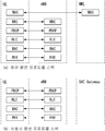
도 3은 본 발명이 적용될 수 있는 무선 통신 시스템에서 E-UTRAN 및 EPC의 구조를 예시한다. 3 illustrates the structure of an E-UTRAN and an EPC in a wireless communication system to which the present invention can be applied.
도 3을 참조하면, eNB는 게이트웨이(예를 들어, MME)의 선택, 무선 자원 제어(RRC: radio resource control) 활성(activation) 동안 게이트웨이로의 라우팅, 방송 채널(BCH: broadcast channel)의 스케줄링 및 전송, 상향링크 및 하향링크에서 UE로 동적 자원 할당, 그리고 LTE_ACTIVE 상태에서 이동성 제어 연결의 기능을 수행할 수 있다. 상술한 바와 같이, EPC 내에서 게이트웨이는 페이징 개시(orgination), LTE_IDLE 상태 관리, 사용자 평면(user plane)의 암호화(ciphering), 시스템 구조 진화(SAE: System Architecture Evolution) 베어러 제어, 그리고 NAS 시그널링의 암호화(ciphering) 및 무결성(intergrity) 보호의 기능을 수행할 수 있다. Referring to FIG. 3, an eNB may select a gateway (eg, MME), route to the gateway during radio resource control (RRC) activation, scheduling of a broadcast channel (BCH), and the like. Dynamic resource allocation to the UE in transmission, uplink and downlink, and may perform the function of mobility control connection in the LTE_ACTIVE state. As mentioned above, within the EPC, the gateway is responsible for paging initiation, LTE_IDLE state management, ciphering of the user plane, System Architecture Evolution (SAE) bearer control, and NAS signaling encryption. It can perform the functions of ciphering and integrity protection.
도 4는 본 발명이 적용될 수 있는 무선 통신 시스템에서 단말과 E-UTRAN 사이의 무선 인터페이스 프로토콜(radio interface protocol) 구조를 나타낸다. 4 shows a structure of a radio interface protocol between a terminal and an E-UTRAN in a wireless communication system to which the present invention can be applied.
도 4(a)는 제어 평면(control plane)에 대한 무선 프로토콜 구조를 나타내고, 도 4(b)는 사용자 평면(user plane)에 대한 무선 프로토콜 구조를 나타낸다.FIG. 4 (a) shows the radio protocol structure for the control plane and FIG. 4 (b) shows the radio protocol structure for the user plane.
도 4를 참조하면, 단말과 E-UTRAN 사이의 무선 인터페이스 프로토콜의 계층들은 통신 시스템의 기술분야에 공지된 널리 알려진 개방형 시스템 간 상호접속(OSI: open system interconnection) 표준 모델의 하위 3 계층에 기초하여 제1 계층(L1), 제2 계층 (L2) 및 제3 계층 (L3)으로 분할될 수 있다. 단말과 E-UTRAN 사이의 무선 인터페이스 프로토콜은 수평적으로 물리계층(physical layer), 데이터링크 계층(data link layer) 및 네트워크 계층(network layer)으로 이루어지며, 수직적으로는 데이터 정보 전송을 위한 프로토콜 스택(protocol stack) 사용자 평면(user plane)과 제어신호(signaling) 전달을 위한 프로토콜 스택인 제어 평면(control plane)으로 구분된다. Referring to FIG. 4, the layers of the air interface protocol between the terminal and the E-UTRAN are based on the lower three layers of the open system interconnection (OSI) standard model known in the art of communication systems. It may be divided into a first layer L1, a second layer L2, and a third layer L3. The air interface protocol between the UE and the E-UTRAN consists of a physical layer, a data link layer, and a network layer horizontally, and vertically stacks a protocol stack for transmitting data information. (protocol stack) It is divided into a user plane and a control plane, which is a protocol stack for transmitting control signals.
제어평면은 단말과 네트워크가 호를 관리하기 위해서 이용하는 제어 메시지들이 전송되는 통로를 의미한다. 사용자 평면은 애플리케이션 계층에서 생성된 데이터, 예를 들어, 음성 데이터 또는 인터넷 패킷 데이터 등이 전송되는 통로를 의미한다. 이하, 무선 프로토콜의 제어평면과 사용자평면의 각 계층을 설명한다.The control plane refers to a path through which control messages used by the terminal and the network to manage a call are transmitted. The user plane refers to a path through which data generated at an application layer, for example, voice data or Internet packet data, is transmitted. Hereinafter, each layer of the control plane and the user plane of the radio protocol will be described.
제1 계층(L1)인 물리 계층(PHY: physical layer)은 물리 채널(physical channel)을 사용함으로써 상위 계층으로의 정보 송신 서비스(information transfer service)를 제공한다. 물리 계층은 상위 레벨에 위치한 매체 접속 제어(MAC: medium access control) 계층으로 전송 채널(transport channel)을 통하여 연결되고, 전송 채널을 통하여 MAC 계층과 물리 계층 사이에서 데이터가 전송된다. 전송 채널은 무선 인터페이스를 통해 데이터가 어떻게 어떤 특징으로 전송되는가에 따라 분류된다. 그리고, 서로 다른 물리 계층 사이, 송신단의 물리 계층과 수신단의 물리 계층 간에는 물리 채널(physical channel)을 통해 데이터가 전송된다. 물리 계층은 OFDM(orthogonal frequency division multiplexing) 방식으로 변조되며, 시간과 주파수를 무선 자원으로 활용한다.A physical layer (PHY), which is a first layer (L1), provides an information transfer service to a higher layer by using a physical channel. The physical layer is connected to a medium access control (MAC) layer located at a higher level through a transport channel, and data is transmitted between the MAC layer and the physical layer through the transport channel. Transport channels are classified according to how and with what characteristics data is transmitted over the air interface. In addition, data is transmitted between different physical layers through a physical channel between a physical layer of a transmitter and a physical layer of a receiver. The physical layer is modulated by an orthogonal frequency division multiplexing (OFDM) scheme and utilizes time and frequency as radio resources.
물리 계층에서 사용되는 몇몇 물리 제어 채널들이 있다. 물리 하향링크 제어 채널(PDCCH: physical downlink control channel)는 단말에게 페이징 채널(PCH: paging channel)와 하향링크 공유 채널(DL-SCH: downlink shared channel)의 자원 할당 및 상향링크 공유 채널(UL-SCH: uplink shared channel)과 관련된 HARQ(hybrid automatic repeat request) 정보를 알려준다. 또한, PDCCH는 단말에게 상향링크 전송의 자원 할당을 알려주는 상향링크 승인(UL grant)를 나를 수 있다. 물리 제어 포맷 지시자 채널(PDFICH: physical control format indicator channel)는 단말에게 PDCCH들에 사용되는 OFDM 심볼의 수를 알려주고, 매 서브프레임마다 전송된다. 물리 HARQ 지시자 채널(PHICH: physical HARQ indicator channel)는 상향링크 전송의 응답으로 HARQ ACK(acknowledge)/NACK(non-acknowledge) 신호를 나른다. 물리 상향링크 제어 채널(PUCCH: physical uplink control channel)은 하향링크 전송에 대한 HARQ ACK/NACK, 스케줄링 요청 및 채널 품질 지시자(CQI: channel quality indicator) 등과 같은 상향링크 제어 정보를 나른다. 물리 상향링크 공유 채널(PUSCH: physical uplink shared channel)은 UL-SCH을 나른다.There are several physical control channels used at the physical layer. A physical downlink control channel (PDCCH) is a resource allocation of a paging channel (PCH) and a downlink shared channel (DL-SCH) and uplink shared channel (UL-SCH) to the UE. : informs hybrid automatic repeat request (HARQ) information associated with an uplink shared channel (HARQ). In addition, the PDCCH may carry an UL grant that informs the UE of resource allocation of uplink transmission. The physical control format indicator channel (PDFICH) informs the UE of the number of OFDM symbols used for PDCCHs and is transmitted every subframe. A physical HARQ indicator channel (PHICH) carries a HARQ acknowledgment (ACK) / non-acknowledge (NACK) signal in response to uplink transmission. The physical uplink control channel (PUCCH) carries uplink control information such as HARQ ACK / NACK, downlink request and channel quality indicator (CQI) for downlink transmission. A physical uplink shared channel (PUSCH) carries a UL-SCH.
제2 계층(L2)의 MAC 계층은 논리 채널(logical channel)을 통하여 상위 계층인 무선 링크 제어(RLC: radio link control) 계층에게 서비스를 제공한다. 또한, MAC 계층은 논리 채널과 전송 채널 간의 맵핑 및 논리 채널에 속하는 MAC 서비스 데이터 유닛(SDU: service data unit)의 전송 채널 상에 물리 채널로 제공되는 전송 블록(transport block)으로의 다중화/역다중화 기능을 포함한다. The MAC layer of the second layer (L2) provides a service to a radio link control (RLC) layer, which is a higher layer, through a logical channel. In addition, the MAC layer multiplexes / demultiplexes into a transport block provided as a physical channel on a transport channel of a MAC service data unit (SDU) belonging to the logical channel and mapping between the logical channel and the transport channel. Includes features
제2 계층(L2)의 RLC 계층은 신뢰성 있는 데이터 전송을 지원한다. RLC 계층의 기능은 RLC SDU의 연결(concatenation), 분할(segmentation) 및 재결합(reassembly)을 포함한다. 무선 베어러(RB: radio bearer)가 요구하는 다양한 QoS(quality of service)를 보장하기 위해, RLC 계층은 투명 모드(TM: transparent mode), 비확인 모드(UM: unacknowledged mode) 및 확인 모드(AM: acknowledge mode)의 세 가지의 동작 모드를 제공한다. AM RLC는 ARQ(automatic repeat request)를 통해 오류 정정을 제공한다. 한편, MAC 계층이 RLC 기능을 수행하는 경우에 RLC 계층은 MAC 계층의 기능 블록으로 포함될 수 있다. The RLC layer of the second layer (L2) supports reliable data transmission. Functions of the RLC layer include concatenation, segmentation, and reassembly of RLC SDUs. In order to guarantee the various quality of service (QoS) required by the radio bearer (RB), the RLC layer has a transparent mode (TM), an unacknowledged mode (UM) and an acknowledgment mode (AM). There are three modes of operation: acknowledge mode. AM RLC provides error correction through an automatic repeat request (ARQ). Meanwhile, when the MAC layer performs an RLC function, the RLC layer may be included as a functional block of the MAC layer.
제2 계층(L2)의 패킷 데이터 컨버전스 프로토콜(PDCP: packet data convergence protocol) 계층은 사용자 평면에서 사용자 데이터의 전달, 헤더 압축(header compression) 및 암호화(ciphering) 기능을 수행한다. 헤더 압축 기능은 작은 대역폭을 가지는 무선 인터페이스를 통하여 IPv4(internet protocol version 4) 또는 IPv6(internet protocol version 6)와 같은 인터넷 프로토콜(IP: internet protocol) 패킷을 효율적으로 전송되게 하기 위하여 상대적으로 크기가 크고 불필요한 제어 정보를 담고 있는 IP 패킷 헤더 사이즈를 줄이는 기능을 의미한다. 제어 평면에서의 PDCP 계층의 기능은 제어 평면 데이터의 전달 및 암호화/무결정 보호(integrity protection)을 포함한다.The packet data convergence protocol (PDCP) layer of the second layer (L2) performs user data transmission, header compression, and ciphering functions in the user plane. Header compression is relatively large and large in order to allow efficient transmission of Internet protocol (IP) packets, such as IPv4 (internet protocol version 4) or IPv6 (internet protocol version 6), over a small bandwidth wireless interface. It means the function to reduce the IP packet header size that contains unnecessary control information. The function of the PDCP layer in the control plane includes the transfer of control plane data and encryption / integrity protection.
제3 계층(L3)의 최하위 부분에 위치한 무선 자원 제어(RRC: radio resource control) 계층은 제어 평면에만 정의된다. RRC 계층은 단말과 네트워크 간의 무선 자원을 제어하는 역할을 수행한다. 이를 위해 단말과 네트워크는 RRC 계층을 통해 RRC 메시지를 서로 교환한다. RRC 계층은 무선 베어러들의 설정(configuration), 재설정(re-configuration) 및 해제(release)와 관련하여 논리 채널, 전송 채널 및 물리 채널을 제어한다. 무선 베어러는 단말과 네트워크 사이의 데이터 전송을 위하여 제2 계층(L2)에 의하여 제공되는 논리적인 경로를 의미한다. 무선 베어러가 설정된다는 것은 특정 서비스를 제공하기 위해 무선 프로토콜 계층 및 채널의 특성을 규정하고, 각각의 구체적인 파라미터 및 동작 방법을 설정하는 것을 의미한다. 무선 베어러는 다시 시그널링 무선 베어러(SRB: signaling RB)와 데이터 무선 베어러(DRB: data RB) 두 가지로 나눠 질 수 있다. SRB는 제어 평면에서 RRC 메시지를 전송하는 통로로 사용되며, DRB는 사용자 평면에서 사용자 데이터를 전송하는 통로로 사용된다.A radio resource control (RRC) layer located at the lowest part of the third layer L3 is defined only in the control plane. The RRC layer serves to control radio resources between the terminal and the network. To this end, the UE and the network exchange RRC messages with each other through the RRC layer. The RRC layer controls the logical channel, transport channel and physical channel with respect to configuration, re-configuration and release of radio bearers. The radio bearer means a logical path provided by the second layer (L2) for data transmission between the terminal and the network. Establishing a radio bearer means defining characteristics of a radio protocol layer and a channel to provide a specific service, and setting each specific parameter and operation method. The radio bearer may be further divided into two signaling radio bearers (SRBs) and data radio bearers (DRBs). The SRB is used as a path for transmitting RRC messages in the control plane, and the DRB is used as a path for transmitting user data in the user plane.
RRC 계층 상위에 위치하는 NAS(non-access stratum) 계층은 세션 관리(session management)와 이동성 관리(mobility management) 등의 기능을 수행한다. A non-access stratum (NAS) layer located above the RRC layer performs functions such as session management and mobility management.
기지국을 구성하는 하나의 셀은 1.25, 2.5, 5, 10, 20Mhz 등의 대역폭 중 하나로 설정되어 여러 단말에게 하향 또는 상향 전송 서비스를 제공한다. 서로 다른 셀은 서로 다른 대역폭을 제공하도록 설정될 수 있다.One cell constituting the base station is set to one of the bandwidth, such as 1.25, 2.5, 5, 10, 20Mhz to provide a downlink or uplink transmission service to multiple terminals. Different cells may be configured to provide different bandwidths.
네트워크에서 단말로 데이터를 전송하는 하향 전송채널(downlink transport channel)은 시스템 정보를 전송하는 방송 채널(BCH: broadcast channel), 페이징 메시지를 전송하는 PCH, 사용자 트래픽이나 제어메시지를 전송하는 DL-SCH 등이 있다. 하향 멀티캐스트 또는 방송 서비스의 트래픽 또는 제어메시지의 경우 DL-SCH를 통해 전송될 수도 있고, 또는 별도의 하향 멀티캐스트 채널(MCH: multicast channel)을 통해 전송될 수도 있다. 한편, 단말에서 네트워크로 데이터를 전송하는 상향 전송채널(uplink transport channel)로는 초기 제어메시지를 전송하는 랜덤 액세스 채널(RACH: random access channel), 사용자 트래픽이나 제어메시지를 전송하는 UL-SCH(uplink shared channel)가 있다. A downlink transport channel for transmitting data from a network to a terminal includes a broadcast channel (BCH) for transmitting system information, a PCH for transmitting a paging message, and a DL-SCH for transmitting user traffic or control messages. There is this. Traffic or control messages of the downlink multicast or broadcast service may be transmitted through the DL-SCH or may be transmitted through a separate downlink multicast channel (MCH). Meanwhile, an uplink transport channel for transmitting data from a terminal to a network includes a random access channel (RACH) for transmitting an initial control message, and an UL-SCH (uplink shared) for transmitting user traffic or a control message. channel).
논리 채널(logical channel)은 전송 채널의 상위에 있으며, 전송 채널에 맵핑된다. 논리 채널은 제어 영역 정보의 전달을 위한 제어 채널과 사용자 영역 정보의 전달을 위한 트래픽 채널로 구분될 수 있다. 제어 채널로는 방송 제어 채널(BCCH: broadcast control channel), 페이징 제어 채널(PCCH: paging control channel), 공통 제어 채널(CCCH: common control channel), 전용 제어 채널(DCCH: dedicated control channel), 멀티캐스트 제어 채널(MCCH: multicast control channel) 등이 있다. 트래픽 채널로는 전용 트래픽 채널(DTCH: dedicated traffic channel), 멀티캐스트 트래픽 채널(MTCH: multicast traffic channel) 등이 있다. PCCH는 페이징 정보를 전달하는 하향링크 채널이고, 네트워크가 UE가 속한 셀을 모를 때 사용된다. CCCH는 네트워크와의 RRC 연결을 가지지 않는 UE에 의해 사용된다. MCCH 네트워크로부터 UE로의 MBMS(Multimedia Broadcast and Multicast Service) 제어 정보를 전달하기 위하여 사용되는 점-대-다점(point-to-multipoint) 하향링크 채널이다. DCCH는 UE와 네트워크 간에 전용 제어 정보를 전달하는 RRC 연결을 가지는 단말에 의해 사용되는 일-대-일(point-to-point) 양방향(bi-directional) 채널이다. DTCH는 상향링크 및 하향링크에서 존재할 수 있는 사용자 정보를 전달하기 위하여 하나의 단말에 전용되는 일-대-일(point-to-point) 채널이다. MTCH는 네트워크로부터 UE로의 트래픽 데이터를 전달하기 위하여 일-대-다(point-to-multipoint) 하향링크 채널이다.The logical channel is on top of the transport channel and is mapped to the transport channel. The logical channel may be divided into a control channel for transmitting control region information and a traffic channel for delivering user region information. The control channel includes a broadcast control channel (BCCH), a paging control channel (PCCH), a common control channel (CCCH), a dedicated control channel (DCCH), multicast And a control channel (MCCH: multicast control channel). Traffic channels include a dedicated traffic channel (DTCH) and a multicast traffic channel (MTCH). PCCH is a downlink channel that carries paging information and is used when the network does not know the cell to which the UE belongs. CCCH is used by a UE that does not have an RRC connection with the network. A point-to-multipoint downlink channel used to convey multimedia broadcast and multicast service (MBMS) control information from an MCCH network to a UE. The DCCH is a point-to-point bi-directional channel used by a terminal having an RRC connection for transferring dedicated control information between the UE and the network. DTCH is a point-to-point channel dedicated to one terminal for transmitting user information that may exist in uplink and downlink. MTCH is a point-to-multipoint downlink channel for carrying traffic data from the network to the UE.
논리 채널(logical channel)과 전송 채널(transport channel) 간 상향링크 연결의 경우, DCCH는 UL-SCH과 매핑될 수 있고, DTCH는 UL-SCH와 매핑될 수 있으며, CCCH는 UL-SCH와 매핑될 수 있다. 논리 채널(logical channel)과 전송 채널(transport channel) 간 하향링크 연결의 경우, BCCH는 BCH 또는 DL-SCH와 매핑될 수 있고, PCCH는 PCH와 매핑될 수 있으며, DCCH는 DL-SCH와 매핑될 수 있으며, DTCH는 DL-SCH와 매핑될 수 있으며, MCCH는 MCH와 매핑될 수 있으며, MTCH는 MCH와 매핑될 수 있다. In the case of an uplink connection between a logical channel and a transport channel, the DCCH may be mapped to the UL-SCH, the DTCH may be mapped to the UL-SCH, and the CCCH may be mapped to the UL-SCH. Can be. In the case of a downlink connection between a logical channel and a transport channel, the BCCH may be mapped with the BCH or DL-SCH, the PCCH may be mapped with the PCH, and the DCCH may be mapped with the DL-SCH. The DTCH may be mapped with the DL-SCH, the MCCH may be mapped with the MCH, and the MTCH may be mapped with the MCH.
도 5는 본 발명이 적용될 수 있는 무선 통신 시스템에서 물리 채널의 구조를 간략히 예시하는 도면이다. 5 is a diagram exemplarily illustrating a structure of a physical channel in a wireless communication system to which the present invention can be applied.
도 5를 참조하면, 물리 채널은 주파수 영역(frequency domain)에서 하나 이상의 서브캐리어와 시간 영역(time domain)에서 하나 이상의 심볼로 구성되는 무선 자원을 통해 시그널링 및 데이터를 전달한다. Referring to FIG. 5, a physical channel transmits signaling and data through a radio resource including one or more subcarriers in a frequency domain and one or more symbols in a time domain.
1.0ms 길이를 가지는 하나의 서브프레임은 복수의 심볼로 구성된다. 서브프레임의 특정 심볼(들)(예를 들어, 서브프레임의 첫번째 심볼)은 PDCCH를 위해 사용될 수 있다. PDCCH는 동적으로 할당되는 자원에 대한 정보(예를 들어, 자원 블록(Resource Block), 변조 및 코딩 방식(MCS: Modulation and Coding Scheme) 등)를 나른다.One subframe having a length of 1.0 ms is composed of a plurality of symbols. The specific symbol (s) of the subframe (eg, the first symbol of the subframe) can be used for the PDCCH. The PDCCH carries information about dynamically allocated resources (eg, a resource block, a modulation and coding scheme (MCS), etc.).
랜덤 액세스 절차(Random Access Procedure)Random Access Procedure
이하에서는 LTE/LTE-A 시스템에서 제공하는 랜덤 액세스 절차(random access procedure)에 대해 살펴본다. Hereinafter, a random access procedure provided by the LTE / LTE-A system will be described.
랜덤 액세스 절차는 단말이 기지국과의 RRC 연결(RRC Connection)이 없어, RRC 아이들 상태에서 초기 접속 (initial access)을 수행하는 경우, RRC 연결 재-확립 절차(RRC connection re-establishment procedure)를 수행하는 경우 등에 수행된다. In the random access procedure, since the terminal does not have an RRC connection with the base station and performs initial access in the RRC idle state, the UE performs an RRC connection re-establishment procedure. Cases are performed.
LTE/LTE-A 시스템에서는 랜덤 액세스 프리앰블(random access preamble, RACH preamble)을 선택하는 과정에서, 특정한 집합 안에서 단말이 임의로 하나의 프리앰블을 선택하여 사용하는 경쟁 기반 랜덤 액세스 절차(contention based random access procedure)과 기지국이 특정 단말에게만 할당해준 랜덤 액세스 프리앰블을 사용하는 비 경쟁 기반 랜덤 액세스 절차(non-contention based random access procedure)을 모두 제공한다. In the LTE / LTE-A system, in the process of selecting a random access preamble (RACH preamble), a contention-based random access procedure in which the UE randomly selects and uses one preamble within a specific set And a non-contention based random access procedure using a random access preamble allocated by a base station only to a specific terminal.
도 6은 본 발명이 적용될 수 있는 무선 통신 시스템에서 경쟁 기반 랜덤 액세스 절차를 설명하기 위한 도면이다.6 is a diagram for explaining a contention based random access procedure in a wireless communication system to which the present invention can be applied.
(1) 제1 메시지(Msg 1, message 1)(1) first message (Msg 1, message 1)
먼저, 단말은 시스템 정보(system information) 또는 핸드오버 명령(handover command)을 통해 지시된 랜덤 액세스 프리앰블의 집합에서 임의로(randomly) 하나의 랜덤 액세스 프리앰블(random access preamble, RACH preamble)을 선택하고, 상기 랜덤 액세스 프리앰블을 전송할 수 있는 PRACH(physical RACH) 자원을 선택하여 전송한다. First, the UE randomly selects one random access preamble (RACH preamble) from a set of random access preambles indicated through system information or a handover command, and A physical RACH (PRACH) resource capable of transmitting a random access preamble is selected and transmitted.
단말로부터 랜덤 액세스 프리앰블을 수신한 기지국은 프리앰블을 디코딩하고, RA-RNTI를 획득한다. 랜덤 액세스 프리앰블이 전송된 PRACH와 관련된 RA-RNTI는 해당 단말이 전송한 랜덤 액세스 프리앰블의 시간-주파수 자원에 따라 결정된다.The base station receiving the random access preamble from the terminal decodes the preamble and obtains an RA-RNTI. The RA-RNTI associated with the PRACH in which the random access preamble is transmitted is determined according to the time-frequency resource of the random access preamble transmitted by the corresponding UE.
(2) 제2 메시지(Msg 2, message 2)(2) a second message (Msg 2, message 2)
기지국은 제1 메시지 상의 프리앰블을 통해서 획득한 RA-RNTI로 지시(address)되는 랜덤 액세스 응답(random access response)을 단말로 전송한다. 랜덤 액세스 응답에는 랜덤 액세스 프리앰블 구분자/식별자(RA preamble index/identifier), 상향링크 무선자원을 알려주는 상향링크 승인(UL grant), 임시 셀 식별자(TC-RNTI: Temporary Cell RNTI) 그리고 시간 동기 값(TAC: time alignment command)들이 포함될 수 있다. TAC는 기지국이 단말에게 상향링크 시간 정렬(time alignment)을 유지하기 위해 보내는 시간 동기 값을 지시하는 정보이다. 단말은 상기 시간 동기 값을 이용하여, 상향링크 전송 타이밍을 갱신한다. 단말이 시간 동기를 갱신하면, 시간 동기 타이머(time alignment timer)를 개시 또는 재시작한다. UL grant는 후술하는 스케줄링 메시지(제3 메시지)의 전송에 사용되는 상향링크 자원 할당 및 TPC(transmit power command)를 포함한다. TPC는 스케줄링된 PUSCH를 위한 전송 파워의 결정에 사용된다.The base station transmits a random access response addressed to the RA-RNTI obtained through the preamble on the first message to the terminal. The random access response includes a random access preamble identifier (RA preamble index / identifier), an uplink grant (UL grant) indicating an uplink radio resource, a temporary cell identifier (TC-RNTI), and a time synchronization value ( TAC: time alignment commands) may be included. The TAC is information indicating a time synchronization value that the base station sends to the terminal to maintain uplink time alignment. The terminal updates the uplink transmission timing by using the time synchronization value. When the terminal updates the time synchronization, a time alignment timer is started or restarted. The UL grant includes an uplink resource allocation and a transmit power command (TPC) used for transmission of a scheduling message (third message), which will be described later. TPC is used to determine the transmit power for the scheduled PUSCH.
단말은 랜덤 액세스 프리앰블을 전송 후에, 기지국이 시스템 정보 또는 핸드오버 명령을 통해 지시된 랜덤 액세스 응답 윈도우(random access response window) 내에서 자신의 랜덤 액세스 응답(random access response)의 수신을 시도하며, PRACH에 대응되는 RA-RNTI로 마스킹된 PDCCH를 검출하고, 검출된 PDCCH에 의해 지시되는 PDSCH를 수신하게 된다. 랜덤 액세스 응답 정보는 MAC PDU(MAC packet data unit)의 형식으로 전송될 수 있으며, 상기 MAC PDU는 PDSCH을 통해 전달될 수 있다. After the UE transmits the random access preamble, the base station attempts to receive its random access response within the random access response window indicated by the system information or the handover command, and PRACH The PDCCH masked by the RA-RNTI corresponding to the PDCCH is detected, and the PDSCH indicated by the detected PDCCH is received. The random access response information may be transmitted in the form of a MAC packet data unit (MAC PDU), and the MAC PDU may be transmitted through a PDSCH.
단말은 기지국에 전송하였던 랜덤 액세스 프리앰블과 동일한 랜덤 액세스 프리앰블 구분자/식별자를 가지는 랜덤 액세스 응답을 성공적으로 수신하면, 랜덤 액세스 응답의 모니터링을 중지한다. 반면, 랜덤 액세스 응답 윈도우가 종료될 때까지 랜덤 액세스 응답 메시지를 수신하지 못하거나, 기지국에 전송하였던 랜덤 액세스 프리앰블과 동일한 랜덤 액세스 프리앰블 구분자를 가지는 유효한 랜덤 액세스 응답을 수신하지 못한 경우 랜덤 액세스 응답의 수신은 실패하였다고 간주되고, 이후 단말은 프리앰블 재전송을 수행할 수 있다.If the terminal successfully receives a random access response having the same random access preamble identifier / identifier as the random access preamble transmitted to the base station, the monitoring stops the random access response. On the other hand, if the random access response message is not received until the random access response window ends, or if a valid random access response having the same random access preamble identifier as the random access preamble transmitted to the base station is not received, the random access response is received. Is considered to have failed, and then the UE may perform preamble retransmission.
(3) 제3 메시지(Msg 3, message 3) (3) third message (Msg 3, message 3)
단말이 자신에게 유효한 랜덤 액세스 응답을 수신한 경우에는, 상기 랜덤 액세스 응답에 포함된 정보들을 각각 처리한다. 즉, 단말은 TAC을 적용시키고, TC-RNTI를 저장한다. 또한, UL grant를 이용하여, 단말의 버퍼에 저장된 데이터 또는 새롭게 생성된 데이터를 기지국으로 전송한다. When the terminal receives a valid random access response to the terminal, it processes each of the information included in the random access response. That is, the terminal applies the TAC, and stores the TC-RNTI. In addition, by using the UL grant, the data stored in the buffer of the terminal or newly generated data is transmitted to the base station.
단말의 최초 접속의 경우, RRC 계층에서 생성되어 CCCH를 통해 전달된 RRC 연결 요청(RRC Connection Request)이 제3 메시지에 포함되어 전송될 수 있으며, RRC 연결 재확립 절차의 경우 RRC 계층에서 생성되어 CCCH를 통해 전달된 RRC 연결 재확립 요청(RRC Connection Re-establishment Request)이 제3 메시지에 포함되어 전송될 수 있다. 또한, NAS 접속 요청 메시지를 포함할 수도 있다. In case of initial access of the UE, an RRC connection request generated in the RRC layer and delivered through the CCCH may be included in the third message and transmitted. In the case of the RRC connection reestablishment procedure, the RRC layer is generated in the RRC layer and CCCH. The RRC connection reestablishment request delivered through the RRC connection reestablishment request may be included in the third message and transmitted. It may also include a NAS connection request message.
제3 메시지는 단말의 식별자가 포함되어야 한다. 단말의 식별자를 포함시키는 방법으로는 두 가지 방법이 존재한다. 첫 번째 방법은 단말이 상기 랜덤 액세스 절차 이전에 이미 해당 셀에서 할당 받은 유효한 셀 식별자(C-RNTI)를 가지고 있었다면, 단말은 상기 UL grant에 대응하는 상향링크 전송 신호를 통해 자신의 셀 식별자를 전송한다. 반면에, 만약 랜덤 액세스 절차 이전에 유효한 셀 식별자를 할당 받지 못하였다면, 단말은 자신의 고유 식별자(예를 들면, S-TMSI 또는 임의 값(random number))를 포함하여 전송한다. 일반적으로 상기의 고유 식별자는 C-RNTI보다 길다. The third message should include the identifier of the terminal. There are two methods for including the identifier of the terminal. In the first method, if the UE has a valid cell identifier (C-RNTI) allocated in the corresponding cell before the random access procedure, the UE transmits its cell identifier through an uplink transmission signal corresponding to the UL grant. do. On the other hand, if a valid cell identifier has not been allocated before the random access procedure, the UE transmits its own unique identifier (eg, S-TMSI or random number). In general, the unique identifier is longer than the C-RNTI.
단말은 상기 UL grant에 대응하는 데이터를 전송하였다면, 충돌 해결을 위한 타이머(contention resolution timer)를 개시한다. If the UE transmits data corresponding to the UL grant, it starts a timer for contention resolution (contention resolution timer).
(4) 제4 메시지(Msg 4, message 4)(4) Fourth message (Msg 4, message 4)
기지국은 단말로부터 제3 메시지를 통해 해당 단말의 C-RNTI를 수신한 경우 수신한 C-RNTI를 이용하여 단말에게 제4 메시지를 전송한다. 반면, 단말로부터 제3 메시지를 통해 상기 고유 식별자(즉, S-TMSI 또는 임의 값(random number))를 수신한 경우, 랜덤 액세스 응답에서 해당 단말에게 할당한 TC-RNTI를 이용하여 제4 메시지를 단말에게 전송한다. 일례로, 제4 메시지는 RRC 연결 설정 메시지(RRC Connection Setup)가 포함할 수 있다. When the base station receives the C-RNTI of the terminal through the third message from the terminal, the base station transmits a fourth message to the terminal using the received C-RNTI. On the other hand, when the unique identifier (ie, S-TMSI or random number) is received from the terminal through the third message, the fourth message is transmitted using the TC-RNTI allocated to the terminal in the random access response. Send to the terminal. For example, the fourth message may include an RRC connection setup message.
단말은 랜덤 액세스 응답에 포함된 UL grant를 통해 자신의 식별자를 포함한 데이터를 전송한 이후, 충돌 해결을 위해 기지국의 지시를 기다린다. 즉, 특정 메시지를 수신하기 위해 PDCCH의 수신을 시도한다. 상기 PDCCH를 수신하는 방법에 있어서도 두 가지 방법이 존재한다. 앞에서 언급한 바와 같이 상기 UL grant에 대응하여 전송된 제3 메시지가 자신의 식별자가 C-RNTI인 경우, 자신의 C-RNTI를 이용하여 PDCCH의 수신을 시도하고, 상기 식별자가 고유 식별자(즉, S-TMSI 또는 임의 값(random number))인 경우에는, 랜덤 액세스 응답에 포함된 TC-RNTI를 이용하여 PDCCH의 수신을 시도한다. 그 후, 전자의 경우, 만약 상기 충돌 해결 타이머가 만료되기 전에 자신의 C-RNTI를 통해 PDCCH를 수신한 경우에, 단말은 정상적으로 랜덤 액세스 절차가 수행되었다고 판단하고, 랜덤 액세스 절차를 종료한다. 후자의 경우에는 상기 충돌 해결 타이머가 만료되기 전에 TC-RNTI를 통해 PDCCH를 수신하였다면, 상기 PDCCH가 지시하는 PDSCH이 전달하는 데이터를 확인한다. 만약 상기 데이터의 내용에 자신의 고유 식별자가 포함되어 있다면, 단말은 정상적으로 랜덤 액세스 절차가 수행되었다고 판단하고, 랜덤 액세스 절차를 종료한다. 제4 메시지를 통해 단말은 C-RNTI를 획득하고, 이후 단말과 네트워크는 C-RNTI를 이용하여 단말 특정 메시지(dedicated message)를 송수신하게 된다. After transmitting the data including its identifier through the UL grant included in the random access response, the terminal waits for an instruction of the base station to resolve the collision. That is, it attempts to receive a PDCCH to receive a specific message. There are two methods for receiving the PDCCH. As mentioned above, when the third message transmitted in response to the UL grant is its C-RNTI, it attempts to receive the PDCCH using its C-RNTI, and the identifier is a unique identifier (that is, In the case of S-TMSI or a random number, it attempts to receive the PDCCH using the TC-RNTI included in the random access response. Then, in the former case, if the PDCCH is received through its C-RNTI before the conflict resolution timer expires, the terminal determines that the random access procedure has been normally performed, and terminates the random access procedure. In the latter case, if the PDCCH is received through the TC-RNTI before the conflict resolution timer expires, the data transmitted by the PDSCH indicated by the PDCCH is checked. If the unique identifier is included in the content of the data, the terminal determines that the random access procedure is normally performed, and terminates the random access procedure. The terminal acquires the C-RNTI through the fourth message, and then the terminal and the network transmit and receive a terminal-specific message using the C-RNTI.
한편, 비경쟁 기반 임의접속 과정에서의 동작은 도 6에 도시된 경쟁 기반 임의접속 과정과 달리 제1 메시지 전송 및 제2 메시지 전송만으로 임의접속 절차가 종료되게 된다. 다만, 제1 메시지로서 단말이 기지국에 임의접속 프리앰블을 전송하기 전에 단말은 기지국으로부터 임의접속 프리앰블을 할당받게 되며, 이 할당받은 임의접속 프리앰블을 기지국에 제1 메시지로서 전송하고, 기지국으로부터 임의접속 응답을 수신함으로써 임의접속 절차가 종료되게 된다.Meanwhile, unlike the contention-based random access procedure illustrated in FIG. 6, the random access procedure is terminated by only transmitting the first message and transmitting the second message. However, before the terminal transmits the random access preamble to the base station as the first message, the terminal is allocated a random access preamble from the base station, and transmits the allocated random access preamble to the base station as a first message, and sends a random access response from the base station. The random access procedure is terminated by receiving.
MTCMTC
(Machine-Type Communication) Machine-Type Communication
도 7은 본 발명이 적용될 수 있는 무선 통신 시스템에서 MTC(Machine-Type Communication) 아키텍처(architecture)를 예시하는 도면이다.7 is a diagram illustrating a Machine-Type Communication (MTC) architecture in a wireless communication system to which the present invention may be applied.
MTC를 위해서 사용되는 단말(또는, MTC 단말)과 MTC 어플리케이션 간의 단-대-단(end-to-end) 어플리케이션은 3GPP 시스템에서 제공되는 서비스들과 MTC 서버에게 제공되는 선택적인 서비스들을 이용할 수 있다. 3GPP 시스템은 MTC를 용이하게 하는 다양한 최적화를 포함하는 수송 및 통신 서비스들(3GPP 베어러 서비스, IMS 및 SMS 포함)을 제공할 수 있다. An end-to-end application between a terminal (or MTC terminal) used for MTC and an MTC application may use services provided by the 3GPP system and optional services provided to the MTC server. . The 3GPP system may provide transport and communication services (including 3GPP bearer services, IMS and SMS) including various optimizations to facilitate MTC.
도 7에서는 MTC를 위해 사용되는 단말이 Um/Uu/LTE-Uu 인터페이스를 통하여 3GPP 네트워크(UTRAN, E-UTRAN, GERAN, I-WLAN 등)으로 연결되는 것을 도시한다. 도 7의 아키텍처는 다양한 MTC 모델(Direct 모델, Indirect 모델, Hybrid 모델)들을 포함한다. In FIG. 7, a terminal used for MTC is connected to a 3GPP network (UTRAN, E-UTRAN, GERAN, I-WLAN, etc.) through a Um / Uu / LTE-Uu interface. The architecture of FIG. 7 includes various MTC models (Direct Model, Indirect Model, Hybrid Model).
먼저, 도 7에서 도시하는 개체(entity)들에 대하여 설명한다. First, the entities shown in FIG. 7 will be described.
도 7에서 어플리케이션 서버는 MTC 어플리케이션이 실행되는 네트워크 상의 서버이다. MTC 어플리케이션 서버에 대해서는 전술한 다양한 MTC 어플리케이션의 구현을 위한 기술이 적용될 수 있으며, 이에 대한 구체적인 설명은 생략한다. 또한, 도 7에서 MTC 어플리케이션 서버는 레퍼런스 포인트 API를 통하여 MTC 서버에 액세스할 수 있으며, 이에 대한 구체적인 설명은 생략한다. 또는, MTC 어플리케이션 서버는 MTC 서버와 함께 위치될(collocated) 수도 있다. In FIG. 7, the application server is a server on a network on which an MTC application is executed. For the MTC application server, the above-described technology for implementing various MTC applications may be applied, and a detailed description thereof will be omitted. In addition, in FIG. 7, the MTC application server may access the MTC server through a reference point API, and a detailed description thereof will be omitted. Alternatively, the MTC Application Server may be collocated with the MTC Server.
MTC 서버(예를 들어, 도 7의 SCS 서버)는 MTC 단말을 관리하는 네트워크 상의 서버이며, 3GPP 네트워크에 연결되어 MTC를 위하여 사용되는 단말 및 PLMN 노드들과 통신할 수 있다. The MTC server (eg, the SCS server of FIG. 7) is a server on a network managing the MTC terminal, and is connected to the 3GPP network to communicate with terminals and PLMN nodes used for MTC.
MTC-IWF(MTC-InterWorking Function)는 MTC 서버와 오퍼레이터 코어 네트워크 간의 상호 동작(interworking)을 관장하고, MTC 동작의 프록시 역할을 할 수 있다. MTC 간접 또는 하이브리드 모델을 지원하기 위해서, MTC-IWF는 레퍼런스 포인트 Tsp 상의 시그널링 프로토콜을 중계하거나 해석하여 PLMN에 특정 기능을 작동시킬 수 있다. MTC-IWF는, MTC 서버가 3GPP 네트워크와의 통신을 수립하기 전에 MTC 서버를 인증(authenticate)하는 기능, MTC 서버로부터의 제어 플레인 요청을 인증하는 기능, 후술하는 트리거 지시와 관련된 다양한 기능 등을 수행할 수 있다. The MTC-Interworking Function (MTC-IWF) manages the interworking between the MTC server and the operator core network and may serve as a proxy for the MTC operation. In order to support the MTC indirect or hybrid model, the MTC-IWF can relay or interpret the signaling protocol on the reference point Tsp to activate certain functions in the PLMN. The MTC-IWF performs the functions of authenticating the MTC server before the MTC server establishes communication with the 3GPP network, authenticating the control plane request from the MTC server, and various functions related to trigger instructions described below. can do.
SMS-SC(Short Message Service-Service Center)/IP-SM-GW(Internet Protocol Short Message GateWay)는 단문서비스(SMS)의 송수신을 관리할 수 있다. SMS-SC는 SME(Short Message Entity)(단문을 송신 또는 수신하는 개체)와 단말 간의 단문을 중계하고, 저장 및 전달하는 기능을 담당할 수 있다. IP-SM-GW는 IP 기반의 단말과 SMS-SC 간의 프로토콜 상호 동작을 담당할 수 있다. Short Message Service-Service Center (SMS-SC) / Internet Protocol Short Message GateWay (IP-SM-GW) may manage transmission and reception of SMS. The SMS-SC may be responsible for relaying, storing, and transmitting a short message between an Short Message Entity (SME) (an entity that transmits or receives a short message) and a terminal. The IP-SM-GW may be in charge of protocol interaction between the IP-based terminal and the SMS-SC.
CDF(Charging Data Function)/CGF(Charging Gateway Function)는 과금에 관련된 동작을 할 수 있다. The charging data function (CDF) / charging gateway function (CGF) may perform an operation related to charging.
HLR/HSS는 가입자 정보(IMSI 등), 라우팅 정보, 설정 정보 등을 저장하고 MTC-IWF에게 제공하는 기능을 할 수 있다. The HLR / HSS may function to store subscriber information (IMSI, etc.), routing information, configuration information, and the like and provide the MTC-IWF.
MSC/SGSN/MME는 단말의 네트워크 연결을 위한 이동성 관리, 인증, 자원 할당 등의 제어 기능을 수행할 수 있다. 후술하는 트리거링과 관련하여 MTC-IWF로부터 트리거 지시를 수신하여 MTC 단말에게 제공하는 메시지의 형태로 가공하는 기능을 수행할 수 있다.The MSC / SGSN / MME may perform a control function such as mobility management, authentication, resource allocation, etc. for the UE's network connection. In connection with the triggering described below, a function of receiving a trigger instruction from the MTC-IWF and processing the message in the form of a message provided to the MTC terminal may be performed.
GGSN(Gateway GPRS Support Node)/S-GW(Serving-Gateway)+P-GW(Packet Date Network-Gateway)는 코어 네트워크와 외부 네트워크의 연결을 담당하는 게이트웨이 기능을 할 수 있다. The Gateway GPRS Support Node (GGSN) / Serving-Gateway (S-GW) + Packet Date Network-Gateway (P-GW) may function as a gateway that manages the connection between the core network and the external network.
표 2는 도 7에서의 주요 레퍼런스 포인트를 정리한 것이다. Table 2 summarizes the main reference points in FIG.
표 2에서 T5a, T5b, T5c 중 하나 이상의 레퍼런스 포인트를 T5라고 지칭한다.In Table 2, one or more reference points of T5a, T5b, and T5c are referred to as T5.
한편, 간접 및 하이브리드 모델의 경우에 MTC 서버와의 사용자 플레인 통신, 및 직접 및 하이브리드 모델의 경우에 MTC 어플리케이션 서버와의 통신은, 레퍼런스 포인트 Gi 및 SGi를 통해서 기존의 프로토콜을 사용하여 수행될 수 있다. On the other hand, user plane communication with the MTC server in the case of indirect and hybrid models, and communication with the MTC application server in the case of direct and hybrid models may be performed using existing protocols through reference points Gi and SGi. .
도 7에서 설명한 내용과 관련된 구체적인 사항은 3GPP TS 23.682 문서를 참조함으로써 본 문서에 병합될 수 있다(incorporated by reference).Specific matters related to the contents described with reference to FIG. 7 may be incorporated into this document by referring to 3GPP TS 23.682 document (incorporated by reference).
도 8은 본 발명이 적용될 수 있는 무선 통신 시스템에서 서비스 능력 노출(Service Capability Exposure)을 위한 아키텍쳐를 예시한다. 8 illustrates an architecture for service capability exposure in a wireless communication system to which the present invention can be applied.
도 8에서 예시하고 있는 서비스 능력 노출(Service Capability Exposure)을 위한 아키텍쳐는 3GPP 네트워크가 3GPP 네트워크 인터페이스에 의해 제공되는 자신의 서비스 및 능력을 외부의 서드 파티 서비스 제공자(3rd party Service Provider) 어플리케이션에게 안전하게 노출하는 것을 가능하게 한다. The architecture for Service Capability Exposure illustrated in FIG. 8 allows the 3GPP network to securely expose its services and capabilities provided by the 3GPP network interface to external third party service provider applications. Makes it possible to do
서비스 능력 노출 기능(SCEF: Service Capability Exposure Function)는 3GPP 네트워크 인터페이스에 의해 제공되는 서비스 및 능력을 안전하게 노출하기 위한 수단을 제공하는 서비스 능력 노출(service capability exposure)을 위한 3GPP 아키텍쳐 내 핵심적인 엔티티(entity)이다. 다시 말해, SCEF는 이동통신 사업자가 운용하는 트러스트 도메인(Trust Domain)에 속하는 서비스 기능 제공을 위한 핵심 엔티티이다. SCEF는 서드 파티 서비스 제공자에게 API 인터페이스를 제공하고, 3GPP의 각종 엔티티와 연결을 통해 서드 파티 서비스 제공자에게 3GPP의 서비스 기능들을 제공한다. SCEF 기능은 SCS에 의해 제공될 수도 있다. Service Capability Exposure Function (SCEF) is a key entity within the 3GPP architecture for service capability exposure that provides a means to securely expose the services and capabilities provided by the 3GPP network interface. )to be. In other words, the SCEF is a key entity for providing a service function belonging to a trust domain operated by a mobile communication operator. SCEF provides an API interface to third party service providers and provides 3GPP service functions to third party service providers through connection with various entities of 3GPP. SCEF functionality may be provided by the SCS.
Tsp 기능이 어플리케이션 프로그램 인터페이스(API: application program interface)를 통해 노출될 수 있는 경우, MTC-IWF는 SCEF와 동일하게 위치(co-located)할 수 있다. 다중의 인자에 의존하여 새로운 3GPP 인터페이스를 특정하기 위한 프로토콜(예를 들어, DIAMETER, RESTful APIs, XML over HTTP, 등)이 선택되며, 여기서 다중의 인자는 요청된 정보의 노출의 용이함 또는 특정 인터페이스의 필요를 포함하나 이에 한정되는 것은 아니다.If the Tsp function may be exposed through an application program interface (API), the MTC-IWF may be co-located with the SCEF. A protocol (eg DIAMETER, RESTful APIs, XML over HTTP, etc.) is selected to specify a new 3GPP interface depending on multiple arguments, where multiple arguments are used to facilitate the disclosure of the requested information or the specific interface. Including but not limited to necessity.
SCEF는 트러스트 도메인(Trust Domain)에 속하는 엔티티로서, 셀룰러 운영자(Cellular operator)에 의해 운용될 수도 있고, 트러스트(trusted) 관계를 맺은 서드 파티(3rd party) 사업자에 의해 운용될 수 있다. 3GPP 릴리즈(Release) 13의 MONTE(Monitoring Enhancement), AESE(Architecture Enhancements for Service Capability Exposure) 등의 워크 아이템 아래 진행 된 서비스 아키텍쳐 노출(Service architecture exposing)을 위한 노드로서, 앞서 도 8과 같이 서비스를 제공할 3GPP 엔티티들과 연결되어 여러 모니터링 및 과금과 관련된 기능들을 외부 서드 파티에 제공하고, 서드 파티 사업자의 통신 패턴 등을 EPS 내부로 설정해 주는 등의 중간에서 관리하는 역할을 한다.The SCEF is an entity belonging to a trust domain, and may be operated by a cellular operator or may be operated by a third party operator that has a trusted relationship. As a node for service architecture exposing under work items such as Monitoring Enhancement (MONTE) and Architecture Enhancements for Service Capability Exposure (AESE) of 3GPP Release 13, the service is provided as shown in FIG. It is connected with 3GPP entities to provide various monitoring and billing functions to external third parties, and manages third party operators' communication patterns in EPS.
RRC 연결 확립(connection establishment) 절차RRC connection establishment procedure
도 9는 본 발명이 적용될 수 있는 무선 통신 시스템에서 RRC 연결 확립 절차를 예시하는 도면이다. 9 is a diagram illustrating an RRC connection establishment procedure in a wireless communication system to which the present invention can be applied.
RRC 연결 확립 절차는 RRC 유휴(RRC Idle) 모드로부터 RRC 연결(RRC Connected) 모드로 천이하기 위하여 사용된다. UE는 eNB에게 어떠한 시그널링 절차, 어떠한 어플리케이션 데이터를 전달하기 전에 RRC Connected 모드로 천이되어야 한다. The RRC connection establishment procedure is used to transition from RRC Idle mode to RRC Connected mode. The UE must transition to RRC Connected mode before delivering any signaling procedure or any application data to the eNB.
RRC 연결 확립 절차는 UE에 의해 개시되나, UE 또는 네트워크에 의해 트리거 될 수 있다. 예를 들어, UE는 네트워크에게 전송할 데이터가 있거나, UE가 새로운 트래킹 영역(tracking area)으로 이동하는 경우 등 RRC 연결 확립 절차를 트리거한다. 또한, 네트워크는 페이징 메시지를 UE에게 전송함으로써 RRC 연결 확립 절차를 트리거한다. The RRC connection establishment procedure is initiated by the UE but can be triggered by the UE or the network. For example, the UE triggers an RRC connection establishment procedure, such as when there is data to send to the network or when the UE moves to a new tracking area. The network also triggers an RRC connection establishment procedure by sending a paging message to the UE.
도 9를 참조하면, 단말은 RRC 연결을 요청하기 위하여 RRC 연결 요청(RRC Connection Request) 메시지를 eNB에게 전송한다(S901). Referring to FIG. 9, the UE transmits an RRC Connection Request message to the eNB in order to request an RRC connection (S901).
RRC Connection Request 메시지는 단말 식별자(UE Identity)(예를 들어, S-TMSI(SAE temporary mobile subscriber identity) 또는 랜덤 ID)와 확립 원인(establishment cause)를 포함한다. The RRC Connection Request message includes a UE ID (eg, SAE temporary mobile subscriber identity (S-TMSI) or random ID) and an establishment cause.
확립 원인(establishment cause)은 NAS 절차(예를 들어, 접속(attach), 접속 해제(detach), 트래킹 영역 업데이트(tracking area update), 서비스 요청(service request), 확장 서비스 요청(extended service request))에 따라 결정된다.The establishment cause may be a NAS procedure (e.g., attach, detach, tracking area update, service request, extended service request). It depends on.
RRC Connection Request 메시지는 랜덤 액세스 절차의 일부로서 전송된다. 즉, RRC Connection Request 메시지는 도 6에서 제3 메시지에 해당한다. The RRC Connection Request message is sent as part of the random access procedure. That is, the RRC Connection Request message corresponds to the third message in FIG. 6.
eNB는 RRC Connection Request 메시지에 대한 응답으로 RRC 연결 설정(RRC Connection Setup) 메시지를 단말에게 전송한다(S902). The eNB transmits an RRC Connection Setup message to the UE in response to the RRC Connection Request message (S902).
RRC Connection Setup 메시지를 수신한 후, 단말은 RRC_CONNECTED 모드로 천이한다.After receiving the RRC Connection Setup message, the terminal transitions to the RRC_CONNECTED mode.
단말은 RRC 연결 확립의 성공적인 완료를 확인하기 위하여 RRC 연결 설정 완료(RRC Connection Setup Complete) 메시지를 eNB으로 전송한다(S903).The UE transmits an RRC Connection Setup Complete message to the eNB to confirm successful completion of RRC connection establishment (S903).
단말은 RRC Connection Setup Complete 메시지에 NAS 메시지(예를 들어, 초기 어태치(Initial Attach) 메시지, 서비스 요청(Service Request) 메시지 등)를 포함시켜 eNB로 전송한다. The terminal transmits the NAS message (eg, an initial attach message, a service request message, etc.) to the eNB in the RRC Connection Setup Complete message.
eNB은 RRC Connection Setup Complete 메시지로부터 Service Request 메시지를 획득하고, 이를 S1AP 메시지인 최초 단말 메시지(Initial UE Message)를 통해 MME에게 전달한다(S904).The eNB obtains a Service Request message from the RRC Connection Setup Complete message and delivers it to the MME through an initial UE message which is an S1AP message (S904).
기지국과 MME 간 제어 신호는 S1-MME 인터페이스에서 S1AP 메시지를 통해 전달된다. S1AP 메시지는 사용자 별로 S1 시그널링 연결을 통하여 전달되고, S1 시그널링 연결은 기지국과 MME가 단말을 식별하기 위하여 할당한 식별자 쌍(즉, eNB UE S1AP ID 및 MME UE S1AP ID)에 의해 정의된다.The control signal between the base station and the MME is transmitted through the S1AP message in the S1-MME interface. The S1AP message is delivered for each user through the S1 signaling connection, and the S1 signaling connection is defined by an identifier pair (ie, eNB UE S1AP ID and MME UE S1AP ID) allocated by the base station and the MME to identify the UE.
eNB는 eNB UE S1AP ID를 할당하여 Initial UE Message에 포함시켜 MME에게 전송하며, MME는 Initial UE Message를 수신하여 MME S1AP UE ID를 할당하여 eNB와 MME 간에 S1 시그널링 연결을 설정한다.The eNB allocates an eNB UE S1AP ID to an Initial UE message and transmits it to the MME. The MME receives an Initial UE message and allocates an MME S1AP UE ID to establish an S1 signaling connection between the eNB and the MME.
NAS 레벨 혼잡 제어(NAS level congestion control)NAS level congestion control
NAS level congestion control은 APN 기반 혼잡 제어(APN(Access Point Name) based congestion control) 및 일반적인 NAS 레벨 이동성 관리 제어(General NAS level Mobility Management control) 기능을 포함한다. NAS level congestion control includes access point name (APN) based congestion control (APN) and general NAS level mobility management control (APN) functions.
여기서, APN은 PDN 식별자(즉, PDN ID)를 의미하며, PDN을 지칭하거나 구분하기 위한 문자열을 의미한다. APN에 의해 UE가 사용해야 하는 P-GW가 결정될 수 있으며, 또한 APN에 의해 UE가 PDN에 연결하기 위한 터널(tunnel)이 정의될 수 있다. 각 PDN 별로 해당 PDN을 식별하기 위한 APN과 해당 PDN과 연관된 하나 이상의 P-GW를 가질 수 있다.Here, APN means a PDN identifier (ie, PDN ID), and means a string for referring to or distinguishing a PDN. The APN may determine the P-GW that the UE should use, and in addition, the APN may define a tunnel for connecting the UE to the PDN. Each PDN may have an APN for identifying the corresponding PDN and one or more P-GWs associated with the corresponding PDN.
APN based congestion control은 특정 APN과 UE에 연관된 EMM(EPS Mobility Management) 및 ESM(EPS Session Management) 시그널링 혼잡을 제어하고 방지하기 위하여 이용된다. UE와 네트워크 모두 EMM 및 ESM 혼잡 제어에 기반한 APN을 제공하기 위하여 이 기능을 지원한다. APN based congestion control is used to control and prevent EPS Mobility Management (EPM) and EPS Session Management (ESM) signaling congestion associated with a particular APN and UE. Both UE and network support this feature to provide APN based on EMM and ESM congestion control.
MME는 APN과 연관된 NAS 시그널링 혼잡을 감지하고(detect), 다음과 같은 기준에 기반하여 APN based congestion control의 수행을 시작/종료할 수 있다. The MME may detect NAS signaling congestion associated with the APN and start / end the performance of the APN based congestion control based on the following criteria.
- APN 별로 활성화된 EPS 베어러의 최대 개수;The maximum number of active EPS bearers per APN;
- APN 별로 EPS 베어러 활성의 최대율(maximum rate);The maximum rate of EPS bearer activity per APN;
- APN의 하나 이상의 P-GW가 MME에게 접근 가능(reachable)하지 않거나 혼잡이 지시됨;One or more P-GWs of the APN are not reachable or congested to the MME;
- 특정 가입된 APN과 장치에 연관된 이동성 관리(MM: Mobility Management) 시그널링의 최대율(maximum rate)Maximum rate of mobility management (MM) signaling associated with a particular subscribed APN and device
- 네트워크 관리 내 셋팅(setting)Settings in network management
MME는 NAS level congestion control을 높은 우선순위의 접속 및 긴급 서비스에는 적용하면 안된다. The MME shall not apply NAS level congestion control to high priority access and emergency services.
General NAS level Mobility Management control과 함께, MME는 일반적인 혼잡 상태 하에서 NAS 레벨 MM 시그널링 요청을 거절할 수 있다. In conjunction with General NAS level Mobility Management control, the MME may reject the NAS level MM signaling request under general congestion.
1) APN 기반 세션 관리 혼잡 제어(APN based Session Management congestion control)1) APN based Session Management congestion control
APN based Session Management congestion control은 예를 들어, MME에서 혼잡 상황으로 인하여 또는 P-GW의 재시작/회복 조건에 의해 또는 특정 APN(들)을 위한 P-GW의 실패/회복에 의해 MME에 의해 활성화될 수 있다. APN based Session Management congestion control may be activated by the MME, for example, due to congestion conditions in the MME or by a restart / recovery condition of the P-GW or by a failure / recovery of the P-GW for a particular APN (s). Can be.
MME는 APN과 연관된 ESM 혼잡이 감지될 때, 세션 관리(SM: Session Management) 백오프(back-off) 타이머를 이용하여 UE로부터의 ESM 요청(예를 들어, PDN 연결(Connectivity), 베어러 자원 할당(Bearer Resource Allocation) 또는 베어러 자원 수정(Bearer Resource Modification) 요청)을 거절할 수 있다. UE가 APN을 제공하지 않으면, MME는 P-GW 선택 절차에서 사용된 APN을 사용한다. When the MME detects an ESM congestion associated with the APN, the MME uses an Session Management (SM) back-off timer to request an ESM from the UE (eg, PDN connectivity, bearer resource allocation). (Bearer Resource Allocation) or Bearer Resource Modification request (Bearer Resource Modification) request can be rejected. If the UE does not provide an APN, the MME uses the APN used in the P-GW selection procedure.
MME는 SM back-off timer와 함께 UE에게 NAS 비활성 EPS 베어러 컨텍스트 요청(NAS Deactivate EPS Bearer Context Request) 메시지를 전송함으로써, 혼잡한 APN에 속하는 PDN 연결을 비활성화할 수 있다. SM back-off timer가 NAS Deactivate EPS Bearer Context Request 내에 셋팅되면, 재활성 요청(reactivation requested) 원인은 셋팅되지 않는다. The MME may deactivate a PDN connection belonging to a congested APN by transmitting a NAS Deactivate EPS Bearer Context Request message to the UE with an SM back-off timer. If the SM back-off timer is set in the NAS Deactivate EPS Bearer Context Request, the reason for reactivation requested is not set.
MME는 APN에 대하여 혼잡 제어가 활성화될 때, 낮은 접속 우선순위 지시자 없는 요청이 MME에 의해 거절되면, UE 및 APN 별로 SM back-off 시간을 저장할 수 있다. MME는 저장된 SM back-off 시간이 만료되기 전에 UE로부터 해당 APN을 타겟팅하는 어떠한 다음의 요청을 즉시 거절할 수 있다. MME가 UE 및 APN 별로 SM back-off 시간을 저장하고 MME가 세션 관리 요청(Session Management Request) 메시지를 혼잡한 APN에 연결된 UE에게 전송하기로 결정하면(예를 들어, 혼잡 상황이 감소되는 이유로 인하여), MME는 어떠한 Session Management Request 메시지를 UE에게 전송하기 전에 SM back-off time을 삭제(clear)한다. When congestion control is activated for the APN, the MME may store the SM back-off time for each UE and APN if the request without the low access priority indicator is rejected by the MME. The MME may immediately reject any subsequent request targeting the APN from the UE before the stored SM back-off time expires. If the MME stores the SM back-off time for each UE and APN and the MME decides to send a Session Management Request message to the UE connected to the congested APN (e.g., for reasons of reduced congestion) ), The MME clears the SM back-off time before sending any Session Management Request message to the UE.
EPS 세션 관리 거절(EPS Session Management reject) 메시지 내에서 또는 NAS Deactivate EPS Bearer Context Request 메시지 내에서 SM back-off timer를 수신할 때, UE는 타이머가 만료될 때까지 다음의 동작을 수행한다. When receiving the SM back-off timer in the EPS Session Management reject message or in the NAS Deactivate EPS Bearer Context Request message, the UE performs the following operation until the timer expires.
- APN이 거절된 EPS 세션 관리 요청(EPS Session Management Request) 메시지 내에서 제공되거나 또는 SM back-off timer가 NAS Deactivate EPS Bearer Context Request 메시지 내에서 수신되면, UE는 혼잡한 APN에 대하여 어떠한 SM 절차를 개시하지 않는다. UE는 다른 APN에 대하여 SM 절차를 개시할 수 있다. If the APN is provided in the rejected EPS Session Management Request message or if the SM back-off timer is received in the NAS Deactivate EPS Bearer Context Request message, the UE may perform any SM procedure for the congested APN. Do not start. The UE may initiate an SM procedure for another APN.
- APN이 거절된 EPS Session Management Request 내에서 제공되지 않으면, UE는 APN 없이 어떠한 SM 요청을 개시하지 않는다. UE는 특정 APN에 대한 SM 절차를 개시할 수 있다. If the APN is not provided within the rejected EPS Session Management Request, the UE does not initiate any SM request without the APN. The UE may initiate an SM procedure for a particular APN.
- Cell/TA(tracking area)/PLMN/RAT 변경되더라도 SM back-off timer는 중단되지 않는다. -SM back-off timer does not stop even if Cell / TA (tracking area) / PLMN / RAT is changed.
- UE는 SM back-off timer가 동작 중이라도 높은 우선순위 접속 및 긴급 서비스를 위한 SM 절차를 개시하도록 허용된다. The UE is allowed to initiate the SM procedure for high priority access and emergency services even when the SM back-off timer is running.
- UE가 SM back-off timer가 동작 중에 혼잡한 APN에 대하여 네트워크에 의해 개시된 EPS 세션 관리 요청(network initiated EPS Session Management Request) 메시지를 수신하면, UE는 이 APN과 연관된 SM back-off timer를 중단시키고, MME에게 응답한다. If the UE receives a network initiated EPS Session Management Request message initiated by the network for a congested APN while the SM back-off timer is running, the UE stops the SM back-off timer associated with this APN. And respond to the MME.
- UE가 낮은 접속 우선순위를 무시하도록 허용이 설정되고, 낮은 접속 우선순위를 가지는 요청에 대한 응답으로 수신된 거절 메시지로 인하여 SM back-off timer가 동작 중이면, UE 내 상위 계층은 낮은 접속 우선순위 없이 SM 절차의 개시를 요청할 수 있다. If the permission is set to allow the UE to ignore low access priority, and the SM back-off timer is running due to a rejection message received in response to a request with a low access priority, then the higher layer in the UE may have a lower access priority. You can request the initiation of an SM procedure without ranking.
UE는 SM back-off timer의 동작 중에도 PDN 단절 절차(PDN disconnection procedure)를 개시하도록 허용된다(예를 들어, PDN 단절 요청(PDN Disconnection) 메시지 전송). The UE is allowed to initiate a PDN disconnection procedure even during operation of the SM back-off timer (for example, sending a PDN disconnection message).
UE가 활성화할 수 있는 모든 APN에 대하여, UE는 개별적인 SM back-off timer를 지원한다. For every APN that the UE can activate, the UE supports a separate SM back-off timer.
다수의 UE가 연기된(deferred) 요청을 (거의) 동시에 개시하는 것을 방지하기 위하여, MME는 연기된 요청이 동기화되지 않도록 SM back-off timer 값을 선택하여야 한다. In order to prevent multiple UEs from initiating (almost) simultaneous deferred requests, the MME should select the SM back-off timer value so that the deferred requests are not synchronized.
APN based Session Management congestion control은 제어 평면 내에서 UE로부터 개시된 NAS ESM 시그널링에 적용 가능하다. SM 혼잡 제어는 UE가 데이터를 송수신하거나 ESM 혼잡 제어 하에 있는 APN(들)을 향하여 사용자 평면 베어러를 활성화하기 위하여 서비스 요청(Service Request) 절차를 개시하는 것을 금지하지 않는다. APN based Session Management congestion control is applicable to NAS ESM signaling initiated from the UE within the control plane. SM congestion control does not prohibit the UE from initiating a service request procedure to send or receive data or activate a user plane bearer towards the APN (s) under ESM congestion control.
2) APN 기반 이동성 관리 혼잡 제어(APN based Mobility Management congestion control)2) APN based Mobility Management congestion control
MME는 MM back-off timer를 이용하여 어태치(Attach) 절차를 거절함으로써 특정한 가입된 APN과 UE에 대한 APN 기반 혼잡 제어를 수행할 수 있다. The MME may perform APN-based congestion control for a specific subscribed APN and UE by rejecting an attach procedure using the MM back-off timer.
혼잡 제어가 특정한 APN과 UE에 대하여 활성화될 때, MM back-off timer는 MME에 의해 UE에게 전송될 수 있다. When congestion control is activated for a particular APN and the UE, the MM back-off timer may be sent to the UE by the MME.
MME가 UE 컨텍스트를 유지하면, 낮은 접속 우선순위 지시자가 없는 요청이 MME에 의해 거절되면, MME는 UE 별로 back-off timer를 저장할 수 있다. MME는 저장된 back-off 시간이 만료되기 전에 UE로부터 어떠한 다음의 요청을 즉시 거절할 수 있다. If the MME maintains the UE context, if the request without the low access priority indicator is rejected by the MME, the MME may store a back-off timer for each UE. The MME may immediately reject any subsequent request from the UE before the stored back-off time expires.
어태치 요청(Attach Request)를 거절한 후에, MME는 일정 시간 동안 가입 데이터(Subscriber Data)를 유지해야 한다. After rejecting an Attach Request, the MME must retain Subscriber Data for a period of time.
이 것은 특정한 가입된 APN에 대하여 UE로부터의 야기된 혼잡 상황이 계속될 때, HSS 시그널링 없이 다음의 요청의 거절을 허용한다. This allows for the rejection of the next request without HSS signaling when the caused congestion situation from the UE continues for a particular subscribed APN.
MM back-off timer가 동작 중에, UE는 MM 절차를 위한 어떠한 NAS 요청을 개시하지 않는다. 그러나, UE는 MM back-off timer가 동작 중이더라도 높은 우선순위 접속 및 긴급 서비스를 위한 MM 절차를 개시하는 것이 허용된다. MM back-off timer가 동작 중에도, 이미 연결 모드라면 UE는 트래킹 영역 업데이트(TAU: Tracking Area Update)를 수행하는 것이 허용된다. While the MM back-off timer is running, the UE does not initiate any NAS request for the MM procedure. However, the UE is allowed to initiate the MM procedure for high priority access and emergency services even when the MM back-off timer is running. Even when the MM back-off timer is in operation, if the UE is already in the connected mode, the UE is allowed to perform a tracking area update (TAU).
MM back-off timer가 동작 중에, 낮은 접속 우선순위를 가지는 요청에 대한 응답으로 수신된 거절 메시지로 인하여 MM back-off timer가 시작되었고, UE 내 상위 계층이 낮은 접속 우선순위 없이 PDN 연결의 확립을 요청하거나 UE가 낮은 접속 우선순위를 가지지 않는 확립된 PDN 연결을 가지는 경우, 낮은 접속 우선순위를 무시하도록 승인이 설정된 UE는 낮은 접속 우선순위 없이 MM 절차를 개시하는 것이 허용된다. While the MM back-off timer is running, the MM back-off timer is started due to a rejection message received in response to a request with a low access priority, and the upper layer in the UE attempts to establish a PDN connection without a low access priority. If the request or the UE has an established PDN connection that does not have a low access priority, then the UE set to grant to ignore the low access priority is allowed to initiate the MM procedure without low access priority.
다수의 UE가 연기된(deferred) 요청을 (거의) 동시에 개시하는 것을 방지하기 위하여, MME는 연기된 요청이 동기화되지 않도록 MM back-off timer 값을 선택하여야 한다. In order to prevent multiple UEs from initiating (almost) simultaneous deferred requests, the MME should select the MM back-off timer value so that the deferred requests are not synchronized.
3) 일반적인 NAS level 이동성 관리 혼잡 제어(General NAS level Mobility Management congestion control)3) General NAS level Mobility Management congestion control
일반적인 오버로드 상태 하에서, MME는 UE로부터 요청된 MM 시그널링을 거절할 수 있다. NAS 요청이 거절되면, MM back-off timer가 MME에 의해 전송될 수 있다. 낮은 접속 우선순위 지시자가 없는 요청이 MME에 의해 거절되고 MME가 UE 컨텍스트를 저장하는 경우, MME는 UE 별로 back-off time을 저장할 수 있다. Under normal overload conditions, the MME may reject the requested MM signaling from the UE. If the NAS request is rejected, an MM back-off timer may be sent by the MME. When a request without a low access priority indicator is rejected by the MME and the MME stores the UE context, the MME may store a back-off time for each UE.
MME는 저장된 back-off time이 만료되기 전에 UE로부터의 어떠한 다음의 요청을 즉시 거절할 수 있다. MM back-off timer가 동작 중에, UE는 디태치 절차(Detach Procedure) 및 높은 우선순위 접속, 긴급 서비스 및 착신(mobile terminated) 서비스를 위한 MM 절차를 제외하고, MM 절차를 위한 어떠한 NAS 요청을 개시하지 않는다. 그러한 Detach 절차 이후에, MM back-off timer는 계속하여 동작된다. MM back-off timer가 동작 중에, 이미 연결 모드라면 UE는 TAU를 수행하는 것이 허용된다. UE가 MM back-off timer가 동작 중에 MME로부터 페이징 요청을 수신하면, UE는 MM back-off timer를 중단하고, 서비스 요청(Service Request) 절차를 개시하거나 TAU 절차를 개시한다. The MME may immediately reject any subsequent request from the UE before the stored back-off time expires. While the MM back-off timer is running, the UE initiates any NAS request for the MM procedure, except for the Detach Procedure and the MM Procedure for High Priority Access, Emergency Services, and Mobile terminated Services. I never do that. After such Detach procedure, the MM back-off timer continues to run. During the operation of the MM back-off timer, the UE is allowed to perform a TAU if it is already in connected mode. When the UE receives a paging request from the MME while the MM back-off timer is in operation, the UE stops the MM back-off timer, initiates a service request procedure, or initiates a TAU procedure.
MM back-off timer가 동작 중에, 낮은 접속 우선순위를 가지는 요청에 대한 응답으로 수신된 거절 메시지로 인하여 MM back-off timer가 시작되었고, UE 내 상위 계층이 낮은 접속 우선순위 없이 PDN 연결의 확립을 요청하거나 UE가 낮은 접속 우선순위를 가지지 않는 확립된 PDN 연결을 가지는 경우, 낮은 접속 우선순위를 무시하도록 승인이 설정된 UE는 낮은 접속 우선순위 없이 MM 절차를 개시하는 것이 허용된다. While the MM back-off timer is running, the MM back-off timer is started due to a rejection message received in response to a request with a low access priority, and the upper layer in the UE attempts to establish a PDN connection without a low access priority. If the request or the UE has an established PDN connection that does not have a low access priority, then the UE set to grant to ignore the low access priority is allowed to initiate the MM procedure without low access priority.
MM back-off timer가 동작 중에, 보고를 제외한 전송에 대하여 승인이 설정된 UE는 보고 없이 제어 평면 Service Request 절차를 개시하는 것이 허용된다. 보고를 제외한 요청에 대한 응답으로 수신된 거절 메시지로 인하여 MM back-off timer가 시작되었으면, MM back-off timer가 동작 중에, UE는 보고를 제외한 제어 평면 Service Request 절차를 개시하지 않는다. While the MM back-off timer is in operation, a UE that has been granted authorization for transmissions other than reporting is allowed to initiate a control plane Service Request procedure without reporting. If the MM back-off timer is started due to the rejection message received in response to the request except for the report, while the MM back-off timer is in operation, the UE does not start the control plane Service Request procedure except for the report.
MM back-off timer는 Cell/RAT 및 PLMN 변경에 영향을 받지 않는다. Cell/RAT 및 TA 변경은 MM back-off timer를 중단하지 않는다. MM back-off timer는 PLMN 재선택을 위한 트리거에 해당하지 않는다. 동등하지 않는 새로운 PLMN이 접속될 때, back-off timer는 중단된다. The MM back-off timer is not affected by Cell / RAT and PLMN changes. Cell / RAT and TA changes do not stop the MM back-off timer. The MM back-off timer is not a trigger for PLMN reselection. When a new, non-equivalent PLMN is connected, the back-off timer is stopped.
다수의 UE가 연기된(deferred) 요청을 (거의) 동시에 개시하는 것을 방지하기 위하여, MME는 연기된 요청이 동기화되지 않도록 MM back-off timer 값을 선택하여야 한다. In order to prevent multiple UEs from initiating (almost) simultaneous deferred requests, the MME should select the MM back-off timer value so that the deferred requests are not synchronized.
UE가 핸드오버 명령을 수신할 때, MM back-off timer가 구동되는지 여부와 무관하게 UE는 핸드오버 절차를 진행한다. When the UE receives a handover command, the UE proceeds with the handover procedure regardless of whether the MM back-off timer is driven.
MME는 UE가 이미 연결 모드 상태일 때 수행된 TAU 절차를 거절하지 않는다. The MME does not reject the TAU procedure performed when the UE is already in connected mode.
유휴 모드 CN 노드 간 이동성에 있어서, MME는 TAU 절차를 거절하고, MM back-off timer 값을 트래킹 영역 거절(Tracking Area Reject) 메시지에 포함시킬 수 있다. For mobility between idle mode CN nodes, the MME may reject the TAU procedure and include the MM back-off timer value in the Tracking Area Reject message.
MME는 UE의 주기적인 TAU 타이머와 암묵적인 디태치 타이머(Implicit Detach timer)의 합보다 큰 MM back-off timer를 이용하여 TAU request 또는 Service request을 거절하는 경우, 디태치(detach)하지 않도록, MME는 접근 가능한 타이머(reachable timer) 및/또는 Implicit Detach timer를 조정하여야 한다. If the MME rejects a TAU request or service request using an MM back-off timer that is greater than the sum of the UE's periodic TAU timer and the implicit detach timer, the MME does not detach the TME request. You may need to adjust the reachable timer and / or the implicit detach timer.
전용 코어 네트워크(Dedicated core network (
DCNDCN
: Dedicated Core Network)Dedicated Core Network
이 기능을 통해 네트워크 운영자는 하나 또는 여러 개의 CN 노드로 구성되는 각 DCN을 사용하여 PLMN 내 다수 개의 DCN을 배치할 수 있다. 각 DCN은 특정 타입의 가입자에게 전용적으로 서비스를 제공할 수 있다. DCN은 하나 이상의 RAT(예를 들어, GERAN, UTRAN, E-UTRAN, WB-E-UTRAN(Wideband E-UTRAN, NB-IoT를 제외한 E-UTRAN의 일부) 및 NB-IoT(Narrowband-Internet of Things))을 위해 배치될 수 있다. 특정 UE 또는 가입자(예를 들어, M2M(Machine-to-Machine) 가입자, 특정 기업 또는 별도의 관리 도메인에 속한 가입자 등)를 구분(isolate)하기 위해 특정한 특성/기능 또는 확장이 DCN에게 제공된다. This feature allows network operators to deploy multiple DCNs within a PLMN using each DCN consisting of one or several CN nodes. Each DCN may provide a service exclusively to a particular type of subscriber. DCNs can include one or more RATs (for example, GERAN, UTRAN, E-UTRAN, WB-E-UTRAN (part of E-UTRAN except Wideband E-UTRAN, NB-IoT)) and Narrowband-Internet of Things Can be arranged for). Specific characteristics / functions or extensions are provided to the DCN to isolate specific UEs or subscribers (eg, machine-to-machine subscribers, subscribers to a particular enterprise or separate management domains, etc.).
DCN은 하나 이상의 MME/SGSN으로 구성되며, 하나 이상의 SGW/PGW/ PCRF(Policy and Charging Rules Function)로 구성 될 수 있다. 이 기능을 사용함으로써, 가입 정보(subscription information)("UE 사용 타입(UE Usage Type)")를 기반으로 가입자는 DCN이 할당되고, DCN에 의해 서비스 받을 수 있다. DCN is composed of one or more MME / SGSN, it may be composed of one or more SGW / PGW / PCRF (Policy and Charging Rules Function). By using this function, a subscriber may be assigned a DCN and serviced by the DCN based on subscription information (“UE Usage Type”).
주요한 특정 기능은 각각의 DCN에서 UE를 라우팅(routing)하고 유지하기 위한다. 아래와 같은 배치 시나리오가 DCN에서 지원된다. The main specific function is to route and maintain the UE in each DCN. The following deployment scenarios are supported in DCN.
- DCN은 단지 하나의 RAT만을 지원하거나(예를 들어, E-UTRAN을 지원하기 위해 전용 MME가 배치되고 전용 SGSN이 배치되지 않음), 다중 RAT를 지원하거나, 또는 모든 RAT를 지원하도록 배치될 수 있다.The DCN may support only one RAT (eg, dedicated MME is deployed to support E-UTRAN and no dedicated SGSN is deployed), support multiple RATs, or deployed to support all RATs. have.
- DCN을 배치하는 네트워크는 기본(default) DCN을 가질 수 있으며, default DCN은 DCN이 이용 가능하지 않거나 또는 UE에게 DCN을 지정(assign)하기 위해 충분한 정보가 이용 가능하지 않은 경우, UE를 관리한다. 동일한 RAN을 모두 공유하는 default DCN과 함께 하나 또는 여러 개의 DCN이 배치될 수 있다.The network deploying the DCN may have a default DCN, which manages the UE if the DCN is not available or if enough information is not available to assign the DCN to the UE. . One or several DCNs may be deployed along with a default DCN that all share the same RAN.
- 아키텍처는 DCN이 PLMN의 일부에만 배치되는 시나리오를 지원한다(예를 들어, 단지 하나의 RAT을 위해 또는 PLMN 영역의 일부에만 배치). 이러한 DCN의 이기종(heterogeneous) 또는 부분 배치는 운영자 배치 및 구성에 따르며, UE가 서비스 영역 또는 DCN을 지원하는 RAT의 내부 또는 외부에 있는지에 따라 다른 특성 또는 기능을 가진 서비스를 제공한다. The architecture supports scenarios in which the DCN is deployed only in part of the PLMN (eg only for one RAT or only in part of the PLMN area). Heterogeneous or partial deployment of these DCNs depends on operator deployment and configuration, and provides services with different characteristics or functions depending on whether the UE is inside or outside the service area or the RAT supporting the DCN.
- DCN이 특정 RAT 또는 PLMN의 서비스 영역을 서비스하도록 배치되지 않더라도, RAT 또는 서비스 영역 내 UE는 여전히 DCN으로부터 PGW에 의해 서비스될 수 있다. Even if the DCN is not arranged to service the service area of a specific RAT or PLMN, the UE in the RAT or service area may still be serviced by the PGW from the DCN.
DCN를 지원하기 위한 상위 레벨 개요는 다음과 같다. The high-level overview for supporting DCN follows.
- 선택적인 가입 정보 파라미터("UE Usage Type")가 DCN의 선택에 사용된다. 운영자는 DCN(들)이 어떠한 UE Usage Type(들)을 서비스하는지 설정한다. HSS는 UE의 가입 정보 내 "UE Usage Type" 값을 MME/SGSN에게 제공한다. An optional subscription information parameter ("UE Usage Type") is used for the selection of the DCN. The operator sets which UE Usage Type (s) the DCN (s) serve. The HSS provides the MME / SGSN with a “UE Usage Type” value in the subscription information of the UE.
- 서빙 네트워크는 운영자의 설정된 매핑(UE Usage Type과 DCN 간), 그리고 지역적으로 설정된 서빙 네트워크에서 이용 가능한 운영자의 정책 및 UE 관련된 컨텍스트 정보(예를 들어, 로밍에 관한 정보)에 기반하여 DCN을 선택한다. 다른 UE Usage Type 값을 가지는 UE들이 동일한 DCN에 의해 서비스될 수 있다. 또한, 동일한 UE Usage Type을 공유하는 UE들도 서로 다른 DCN에 의해 서비스될 수 있다. The serving network selects a DCN based on the operator's configured mapping (between UE Usage Type and DCN), and the operator's policy and UE related context information (eg roaming information) available in the locally configured serving network. do. UEs having different UE Usage Type values may be serviced by the same DCN. In addition, UEs sharing the same UE Usage Type may also be serviced by different DCNs.
- 가입 정보 내 특정 "UE Usage Type" 값을 위한 설정이 없는 경우, 서빙 MME/SGSN은 default DCN에 의해 UE를 서비스하거나 또는 서빙 운영자 특정 정책을 이용하여 DCN을 선택할 수 있다. If there is no setting for a specific "UE Usage Type" value in the subscription information, the serving MME / SGSN may service the UE by the default DCN or select the DCN using the serving operator specific policy.
- "UE Usage Type"은 UE와 연관된다. 즉, UE 가입 별로 단 하나의 "UE Usage Type"이 존재한다. "UE Usage Type" is associated with the UE. That is, there is only one "UE Usage Type" per UE subscription.
- MME의 경우, MME 그룹 식별자(들)(MMEGI: MME group Identifier)는 PLMN 내 DCN을 식별한다. SGSN의 경우, 그룹 식별자(들)(즉, PLMN 내 DCN에 속한 SGSN의 그룹)은 PLMN 내 DCN을 식별한다. 이 식별자는 네트워크 자원 식별자(NRI: network resource identifier)로서 동일한 포맷을 가질 수 있으며(예를 들어, NRI는 서빙 영역 내 특정 SGSN 노드를 식별하지 않는다.), 이 경우 "널-NRI(Null-NRI)"으로 지칭된다. 또는, 이 식별자는 독립된 NRI의 포맷을 가질 수 있으며, 이 경우 "SGSN 그룹 식별자(SGSN Group ID)"로 지칭될 수 있다. "Null-NRI" 또는 "SGSN Group ID"는 SGSN에 의해 Null-NRI/SGSN Group ID에 해당되는 SGSN(들) 그룹으로부터 SGSN을 선택하는 네트워크 노드 선택 기능(NNSF: network node selection function) 절차가 트리거된 RAN에 제공된다. For MME, the MME group identifier (MMEGI) identifies a DCN in the PLMN. In the case of an SGSN, the group identifier (s) (ie, the group of SGSNs belonging to the DCN in the PLMN) identify the DCN in the PLMN. This identifier may have the same format as a network resource identifier (NRI) (for example, the NRI does not identify a particular SGSN node in the serving area), in this case "Null-NRI. ) ". Alternatively, this identifier may have a format of an independent NRI, in which case it may be referred to as an "SGSN Group ID". "Null-NRI" or "SGSN Group ID" is triggered by the network node selection function (NNSF) procedure of selecting an SGSN from the SGSN (s) group corresponding to the Null-NRI / SGSN Group ID by SGSN. Provided to the RAN.
- UE를 서비스하는 전용 MME/SGSN은 UE Usage Type에 기반한 전용 S-GW 및 P-GW을 선택한다. The dedicated MME / SGSN serving the UE selects the dedicated S-GW and P-GW based on the UE Usage Type.
- 네트워크에 최초 액세스 시 RAN에서 특정 DCN을 선택하기 위해 충분한 정보가 이용 가능하지 않으면, RAN은 default DCN으로부터 CN 노드를 선택할 수 있다. 또 다른 DCN으로의 리다이렉션(redirection)이 요구될 수 있다. If there is not enough information available to select a specific DCN in the RAN upon initial access to the network, the RAN may select a CN node from the default DCN. Redirection to another DCN may be required.
- UE를 하나의 DCN으로부터 다른 DCN으로 리다이렉션(redirection)하기 위해, RAN을 통한 리다이렉션(redirection) 절차가 UE의 NAS 메시지를 대상(target) DCN에게 전달하기 위하여 사용된다. In order to redirect the UE from one DCN to another DCN, a redirection procedure via the RAN is used to convey the NAS message of the UE to the target DCN.
- UE(들)을 위한 적절한 DCN을 선택하고 유지하기 위하여, 모든 선택 기능은 RAN 노드의 NNSF를 포함하여 DCN(들)을 알 수 있다. In order to select and maintain the appropriate DCN for the UE (s), all selection functions may know the DCN (s), including the NNSF of the RAN node.
DECOR(Dedicated Core)Dedicated Core (DECOR)
도 10은 본 발명이 적용될 수 있는 무선 통신 시스템에서 전용 코어(DECOR)의 개념을 설명하기 위한 도면이다. 10 is a view for explaining the concept of a dedicated core (DECOR) in a wireless communication system to which the present invention can be applied.
Decor는 MTC/IoT 단말 등 특성 서비스에 더 특화된 서비스가 필요한 단말들을 해당 DCN에 등록시키기 위한 기능이다. 3GPP 릴리즈(Rel)-13에서 UE가 Attach/TAU시 HSS에 저장된 단말의 가입 정보 내 'UE Usage Type'에 의에 해당 단말을 적절한 DCN으로 등록하는 방법이 소개 되었다. Decor is a function for registering terminals requiring services more specialized for a characteristic service such as MTC / IoT terminals in a corresponding DCN. In 3GPP Release (Rel) -13, a method of registering a UE as an appropriate DCN was introduced according to the 'UE Usage Type' in the subscription information of the UE stored in the HSS upon attachment / TAU.
Decor의 경우, UE가 한 번 메인 네트워크(main network)에 등록 된 뒤, DCN으로 리라우팅(rerouting) 해야 하는 단점이 있기 때문에, 단말이 네트워크에 접속(access) 시 한번에 적절한 DCN에 등록 시키기 위해 단말이 네트워크에 적절한 DCN 선택 관련 정보를 제공할 수 있다. In the case of Decor, since the UE has to be rerouted to the DCN after being registered in the main network once, the UE can be registered in the appropriate DCN at a time when the UE accesses the network. It can provide information about DCN selection appropriate for this network.
이에 대하여 살펴보면 다음과 같다. This is as follows.
1) UE 보조(assistance)에 의한 전용 코어 네트워크(DCN: Dedicated Core Network) 선택1) Dedicated Core Network (DCN) Selection by UE Assistance
이 기능은, UE로부터의 보조 정보(assistance information)는 UE와 관련된 DCN을 선택하는 데 필요한 시그널링을 감소 시키기 위한 것이다. 이는 Rel-13 DECOR 선택 메커니즘을 보완한다. 모든 3GPP RAT, 즉 E-UTRAN, UTRAN, GERAN 및 NB-IOT가 지원된다. 이러한 진보(enhancement)는 또한 DCN들 간의 리다이렉션(redirection)을 방지함으로써 전용 코어 네트워크 사이의 분리를 개선 할 수 있다. 즉, 허용되지 않는 DCN에 액세스하는 UE를 방지할 수 있다. UE가 서빙 PLMN을 변경할 때 이 솔루션이 동작되면 유리하다.This function is to reduce the signaling needed to select the DCN associated with the UE assistance information from the UE. This complements the Rel-13 DECOR selection mechanism. All 3GPP RATs are supported, namely E-UTRAN, UTRAN, GERAN and NB-IOT. This enhancement can also improve separation between dedicated core networks by preventing redirection between DCNs. That is, it is possible to prevent the UE from accessing the DCN which is not allowed. It is advantageous if this solution works when the UE changes the serving PLMN.
2) DCN 타입을 위한 혼잡 제어(congestion control)2) Congestion Control for DCN Types
DCN(들)과 함께, UE는 가입 프로파일(subscription profile)에 따라 특정 특성을 가지는 DCN에 의해 서비스될 수 있도록, RAN에 의해 지시된다. RAN 노드가 적절한 DCN을 선택할 수 있도록, UE가 보조 정보(assistance information)를 제공할 수 있다. DCN은 상이한 DCN 타입의 서비스 할 수 있기 때문에, 상이한 DCN 타입을 제공하는 다수의 UE가 동일한 DCN에 의해 서비스되는 경우, 네트워크 상의 혼잡이 증가될 수 있다. 혼잡 제어를 수행하는 현재의 방법은 DCN이 DCN 특성에 기초하여 혼잡 제어를 수행하도록 향상되지 않았기 때문에, eDECOR에 적합하지 않을 수 있다. 오히려, 이들은 다른 측면(예를 들어, 지연 허용오차(delay tolerance))들에 기초하여 혼잡 제어를 가능하게 한다. 그러나, eDECOR를 사용하는 모든 UE들 또한 지연 허용오차(delay tolerance)를 가지도록 설정된다면, 이 요소는 이들 UE들에 대한 DCN 타입에 관계없이, 어느 UE에게 어떻게 혼잡 제어가 적용되어야 하는지를 결정할 때, 주요한 역할을 수행하지 못할 것이다.Along with the DCN (s), the UE is indicated by the RAN so that it can be serviced by a DCN with certain characteristics according to a subscription profile. The UE can provide assistance information so that the RAN node can select the appropriate DCN. Since DCNs can serve different DCN types, congestion on the network can be increased when multiple UEs providing different DCN types are served by the same DCN. Current methods of performing congestion control may not be suitable for eDECOR since the DCN has not been enhanced to perform congestion control based on DCN characteristics. Rather, they enable congestion control based on other aspects (eg delay tolerances). However, if all UEs using eDECOR are also set to have a delay tolerance, then this element is determined when congestion control should be applied to which UE, regardless of the DCN type for these UEs. It will not play a major role.
특정 DCN이 혼잡을 경험하면, 네트워크는 DCN 타입을 기반으로 혼잡을 제어하는 방법을 결정할 필요가 있을 수 있다. 따라서, 이 주요 이슈는 자신이 지원하는 DCN 타입을 기반으로 전용 코어 네트워크에서 혼잡 레벨을 제어하는 솔루션을 제공하는 것을 목표로 한다.If a particular DCN experiences congestion, the network may need to determine how to control congestion based on the DCN type. Therefore, this major issue aims to provide a solution for controlling congestion levels in a dedicated core network based on the DCN types it supports.
즉, 시스템은 DCN 타입에 기반하여 네트워크 상의 혼잡을 제어할 수 있어야 한다. That is, the system should be able to control congestion on the network based on the DCN type.
혼잡 제어(Congestion Control) 방법Congestion Control Method
본 발명은 동일한 DCN(Dedicated Core Network)이 서로 다른 하나 이상의 DCN 타입(type)을 지원하는 코어 네트워크(Core Network)의 혼잡이 발생하는 경우, 서로 다른 DCN type에 대해 개별적인 혼잡 제어 방법을 제안한다. The present invention proposes a separate congestion control method for different DCN types when congestion occurs in a core network in which the same dedicated core network (DCN) supports one or more different DCN types.
혼자 제어 방법으로, 단말이 네트워크 RRC 연결 셋업(RRC connection setup) 시 DCN type을 제공하고 eNB는 제공받은 DCN type에 의해 확장된 대기시간(extended waittime)을 제공하여 백오프(back off) 시키는 메커니즘이 소개되었다. 다만, 이 방법에 따르면, 단말은 매 RRC 셋업 절차를 수행할 때마다, DCN type을 eNB에게 제공해 주어야 하는 단점이 있다.As a control method alone, the UE provides a DCN type during network RRC connection setup and the eNB provides an extended wait time by the provided DCN type to back off. Was introduced. However, according to this method, the UE has to provide a DCN type to the eNB every time the RRC setup procedure is performed.
현재, DCN type은 UE Usage type을 기반으로 구분이 될 수 있다. 또는, DCN type은 사업자 별 정보를 포함하는 DCN 보조 선택 파라미터(DCN assistance selection parameter)로 구분될 수도 있다. TR 23.711의 '솔루션 #1: EPC DCN의 선택을 위한 UE 보조 정보'의 경우, DCN 보조 선택 파라미터를 단말에 제공하여 적절한 DCN 타입을 구별하고자 제안되었고, '솔루션 #3: UE의 RAN으로의 지시 기반의 DCN 선택'의 경우, UE Usage type을 이용하여 DCN을 선택하는 방법이 제안되었다. Currently, the DCN type may be classified based on the UE Usage type. Alternatively, the DCN type may be classified into a DCN assistance selection parameter including information for each operator. In case of 'Solution # 1: UE assistance information for selecting an EPC DCN' of TR 23.711, it has been proposed to provide a UE with a DCN assistance selection parameter to distinguish an appropriate DCN type, and 'Solution # 3: Instruction to the RAN of the UE' Based DCN selection ', a method of selecting a DCN using a UE Usage type has been proposed.
이하, 본 발명의 설명에 있어서, 설명의 편의를 위해 DCN type이 UE Usage type으로 선택될 수 있다고 가정한다. 다만, DCN 보조 선택 파라미터가 이용되는 경우라도, DCN type 구별은 UE Usage Type으로도 충분할 수 있다. Hereinafter, in the description of the present invention, it is assumed that the DCN type may be selected as the UE Usage type for convenience of description. However, even when the DCN auxiliary selection parameter is used, the DCN type distinction may be sufficient as the UE Usage Type.
UE Usage type은 HSS에 저장되어 UE의 어태치(attach) 시 MME로 전달되어 저장되는 정보를 의미한다. 단말 당 하나의 UE Usage Type이 제공된다. MME는 특정 DCN type에 대해 혼잡이 발견되면 해당 UE Usage type을 사용하는 단말에 대해 NAS 레벨 혼잡 제어(NAS level congestion control)를 수행할 수 있다. The UE Usage type refers to information stored in the HSS and transmitted to the MME upon attachment of the UE. One UE Usage Type is provided per terminal. If congestion is detected for a specific DCN type, the MME may perform NAS level congestion control for a terminal using the corresponding UE usage type.
이에 따라, 본 발명에서는 다음과 같이 DCN 특정 혼잡 제어(DCN specific congestion control) 방법을 제안한다. Accordingly, the present invention proposes a DCN specific congestion control method as follows.
1) DCN 특정 NAS 레벨 혼잡 제어(DCN specific NAS level congestion control) 방법1) DCN specific NAS level congestion control method
DCN 특정 NAS 레벨 혼잡 제어(DCN specific NAS level congestion control)는 UE의 특정 DCN에 적용된다. 각 DCN은 하나의 UE 사용 타입(Usage Type)을 가질 수 있다. DCN specific NAS level congestion control is applied to a specific DCN of the UE. Each DCN may have one UE usage type.
UE Usage Type이 HSS 내의 UE의 가입 데이터(subscription data)에 저장되어 있는 경우, UE는 특정 DCN 타입에 속한다. UE Usage Type은 HSS 내의 UE 별로 저장되고, 일반적인 HSS 시그널링의 일부로서 MME에 의해 획득된다. UE는 자신의 UE Usage Type을 알고 있을 수 있다.If the UE Usage Type is stored in subscription data of the UE in the HSS, the UE belongs to a specific DCN type. The UE Usage Type is stored for each UE in the HSS and obtained by the MME as part of general HSS signaling. The UE may know its UE Usage Type.
DCN specific NAS level congestion control은 세션 관리(Session Management) 시그널링 또는 이동성 관리(Mobility Management) 시그널링, 또는 둘 모두에 대하여 활성화 될 수 있다. DCN specific NAS level congestion control은 운영자 정책에 따라 활성화된다.DCN specific NAS level congestion control may be activated for Session Management signaling or Mobility Management signaling, or both. DCN specific NAS level congestion control is activated according to operator policy.
Session Management 시그널링을 위한 DCN specific NAS level congestion control이 특정 DCN 타입에 대해 활성화되면, MME의 동작은 앞서 설명한 APN 기반 세션 관리 혼잡 제어(APN based Session Management congestion control) 방법과 유사하지만 다음과 같이 수정될 수 있다. When DCN specific NAS level congestion control for session management signaling is activated for a specific DCN type, the operation of the MME is similar to the APN based session management congestion control method described above, but can be modified as follows. have.
- MME는 이 특정 DCN에 속하는 UE들에 대해 가입된 모든 APN들에 대해 ESM 혼잡 제어를 적용 할 수 있다.-The MME can apply ESM congestion control for all APNs subscribed to UEs belonging to this particular DCN.
- MME는 Session Management 백-오프(back-off) 타이머를 이용하여 특정 DCN 타입에 속하는 UE로부터의 EPS 세션 관리(ESM: EPS Session Management) 요청(들)(예를 들어, PDN 연결(Connectivity), 베어러 자원 할당(Bearer Resource Allocation) 또는 베어러 자원 수정 요청(Bearer Resource Modification Requests))을 거절한다; 또는 The MME may use an EPS Session Management (ESM) request (s) from a UE belonging to a specific DCN type using a Session Management back-off timer (eg, PDN Connectivity, Reject Bearer Resource Allocation or Bearer Resource Modification Requests; or
- MME는 Session Management 백-오프(back-off) 타이머를 이용하여 특정 DCN 타입 및 특정 APN에 속하는 UE로부터의 EPS 세션 관리(ESM: EPS Session Management) 요청(들)(예를 들어, PDN 연결(Connectivity), 베어러 자원 할당(Bearer Resource Allocation) 또는 베어러 자원 수정 요청(Bearer Resource Modification Requests))을 거절한다.The MME uses a Session Management back-off timer to request EPS Session Management (ESM) request (s) from a UE belonging to a specific DCN type and a specific APN (e.g., PDN connection ( Connectivity), bearer resource allocation (Bearer Resource Allocation) or bearer resource modification requests (Bearer Resource Modification Requests).
세션 관리(Session Management) 백-오프(back-off) 타이머는 특정 DCN 타입 및 APN과 연관 될 수 있으며, Session Management 시그널링을 위한 DCN specific NAS level congestion control을 위한 ESM(EPS Session Management) 요청(들) 내에서 UE에게 특정 (거절) 원인이 제공될 수 있다. Session Management back-off timer can be associated with a specific DCN type and APN, EPS Session Management (ESM) request (s) for DCN specific NAS level congestion control for Session Management signaling The UE may be given a specific (decline) cause within.
(거절) 원인 값(들)은 Session Management 시그널링을 위한 DCN specific NAS level congestion control을 위한 특정 DCN 타입과 APN 별로 제공될 수 있다. 공통된 (거절) 원인 값이 모든 DCN 타입(들) 및 APN(들)에서 사용될 수 있으며, 또는 서로 다른 (거절) 원인 값(들)이 각 DCN 타입 및 APN 별로 사용될 수도 있다. (Rejected) The cause value (s) may be provided for each specific DCN type and APN for DCN specific NAS level congestion control for Session Management signaling. A common (reject) cause value may be used for all DCN type (s) and APN (s), or different (reject) cause value (s) may be used for each DCN type and APN.
UE는 백-오프 타이머가 만료 될 때까지 동일한 DCN 타입 및/또는 동일한 APN에 대한 PLMN 내 네트워크에게 ESM(EPS Session Management) 요청(들)을 요청해서는 안 된다. The UE should not request the EPS Session Management (ESM) request (s) from the network in the PLMN for the same DCN type and / or the same APN until the back-off timer expires.
Mobility Management 시그널링을 위한 DCN specific NAS level congestion control이 특정 DCN 타입에 대해 활성화되면, MME의 동작은 앞서 설명한 APN 기반 이동성 관리 혼잡 제어(APN based Mobility Management congestion control) 방법과 유사하지만, 특정 APN에 가입되기 보다는 특정 DCN에 가입된 UE에 적용될 수 있다. When DCN specific NAS level congestion control for Mobility Management signaling is activated for a specific DCN type, the operation of the MME is similar to the APN based Mobility Management congestion control method described above, but is subscribed to a specific APN. Rather, it can be applied to a UE subscribed to a specific DCN.
- MME는 Mobility Management 백-오프(back-off) 타이머를 이용하여 특정 DCN 타입에 속하는 UE로부터의 EPS 이동성 관리(EMM: EPS Mobility Management) 요청(들)(예를 들어, 어태치 요청(Attach Request), 트래킹 영역 업데이트 요청(Tracking Area Update Request) 또는 서비스 요청(Service Request) 또는 확장된 서비스 요청(Extended Service Request))을 거절한다. The MME may use EPS Mobility Management (EMM) request (s) from a UE belonging to a specific DCN type (eg, Attach Request) using a Mobility Management back-off timer. ), Reject a tracking area update request or a service request or an extended service request.
Mobility Management 백 오프 타이머는 이 특정 DCN 유형과 연관 될 수 있으며, Mobility Management 시그널링을 위한 DCN specific NAS level congestion control을 위한 EMM(EPS Mobility Management) 요청(들) 메시지(들) 내에서 UE에게 특정 (거절) 원인이 제공될 수 있다. The Mobility Management backoff timer may be associated with this specific DCN type and may be specific to the UE within the EPS Mobility Management (EMM) request (s) message (s) for DCN specific NAS level congestion control for Mobility Management signaling. Cause may be provided.
(거절) 원인 값(들)은 Mobility Management 시그널링을 위한 DCN specific NAS level congestion control을 위한 특정 DCN 타입 별로 제공될 수 있다. 공통된 (거절) 원인 값이 모든 DCN 타입(들)에서 사용될 수 있으며, 또는 서로 다른 (거절) 원인 값(들)이 각 DCN 타입 별로 사용될 수도 있다. UE는 특정 (거절) 원인 값(들)에 기반하여 RAT(radio access technology, 예를 들어, GERAN 또는 UTRAN) 및/또는 PLMN의 선택을 시도할 수 있다. (Rejected) The cause value (s) may be provided for each specific DCN type for DCN specific NAS level congestion control for Mobility Management signaling. A common (reject) cause value may be used for all DCN type (s), or different (reject) cause value (s) may be used for each DCN type. The UE may attempt to select a radio access technology (e.g., GERAN or UTRAN) and / or PLMN based on the specific (rejected) cause value (s).
UE는 백-오프 타이머가 만료 될 때까지 동일한 DCN 타입에 대한 PLMN 내 네트워크에게 EMM(EPS Mobility Management) 요청(들)을 요청해서는 안 된다. The UE should not request the EPS Mobility Management (EMM) request (s) from the network in the PLMN for the same DCN type until the back-off timer expires.
DCN specific NAS level congestion control은 HSS에 의해 제공된 UE의 가입 정보(subscription information)에 기반하여 MME에서 수행된다. 따라서, 이는 UE에게 어떠한 영향도 미치지 않는다. DCN specific NAS level congestion control is performed in the MME based on the subscription information of the UE provided by the HSS. Thus, this does not have any effect on the UE.
도 11은 본 발명의 일 실시예에 따른 혼잡 제어 방법을 예시하는 도면이다. 11 is a diagram illustrating a congestion control method according to an embodiment of the present invention.
도 11을 참조하면, MME/SGSN은 상기 MME/SGSN에 의해 서빙(serving)되는 하나 이상의 DCN의 혼잡을 감지(detect)할 수 있다(S1101).Referring to FIG. 11, the MME / SGSN may detect congestion of one or more DCNs served by the MME / SGSN (S1101).
즉, 다수의 DCN들을 서빙(serving)하는 MME/SGSN은 다수의 DCN들을 중 하나 또는 그 이상의 DCN(들)의 혼잡을 감지할 수 있다. That is, an MME / SGSN serving multiple DCNs can detect congestion of one or more DCN (s) of the multiple DCNs.
예를 들어, MME/SGSN는 다음과 같은 기준으로 DCN(들)의 혼잡을 감지할 수 있다. For example, the MME / SGSN may detect congestion of the DCN (s) based on the following criteria.
- DCN 별로 활성화된 EPS 베어러의 최대 개수가 미리 정해진 임계치 이상(초과)인 경우;The maximum number of activated EPS bearers per DCN is greater than or equal to a predetermined threshold (greater than);
- DCN 별로 EPS 베어러 활성의 최대율(maximum rate)이 미리 정해진 임계치 이상(초과)인 경우;The maximum rate of EPS bearer activity per DCN is above a predetermined threshold (over);
- DCN의 하나 이상의 P-GW가 MME에게 접근 가능(reachable)하지 않거나 혼잡이 지시되는 경우;One or more P-GWs of the DCN are not reachable or congested to the MME;
- 특정 DCN과 장치에 연관된 이동성 관리(MM: Mobility Management) 시그널링의 최대율(maximum rate)이 미리 정해진 임계치 이상(초과)인 경우When the maximum rate of mobility management (MM) signaling associated with a particular DCN and device is above (over) a predetermined threshold
- 네트워크 관리 내 셋팅(setting)Settings in network management
MME/SGSN는 UE로부터 NAS 요청 메시지를 수신한다(S1102).The MME / SGSN receives a NAS request message from the UE (S1102).
NAS 요청 메시지는 세션 관리(SM: Session Management) 요청 메시지 및/또는 이동성 관리(MM: Mobility Management) 요청 메시지를 포함할 수 있다. The NAS request message may include a session management (SM) request message and / or a mobility management (MM) request message.
예를 들어, SM 요청 메시지는 PDN 연결 요청(PDN Connectivity Request) 메시지, 베어러 자원 할당 요청(Bearer Resource Allocation Request) 메시지 및/또는 베어러 자원 수정 요청(Bearer Resource Modification Requests) 메시지를 포함할 수 있다. For example, the SM request message may include a PDN Connectivity Request message, a Bearer Resource Allocation Request message, and / or a Bearer Resource Modification Requests message.
또한, MM 요청 메시지는 어태치 요청(Attach Request) 메시지, 트래킹 영역 업데이트 요청(Tracking Area Update Request) 메시지, 서비스 요청(Service Request) 메시지 및/또는 확장된 서비스 요청(Extended Service Request) 메시지를 포함할 수 있다. In addition, the MM request message may include an Attach Request message, a Tracking Area Update Request message, a Service Request message, and / or an Extended Service Request message. Can be.
MME/SGSN는 HSS로부터 UE의 가입 정보(subscription information)/데이터(data)를 획득한다(S1103).The MME / SGSN obtains subscription information / data of the UE from the HSS (S1103).
이때, 가입 정보는 UE 사용 타입(UE Usage Type)을 포함할 수 있다. UE Usage Type은 HSS 내의 UE 별로 저장될 수 있다. In this case, the subscription information may include a UE usage type. The UE Usage Type may be stored for each UE in the HSS.
MME/SGSN는 UE Usage Type에 기반하여 UE를 서빙(serving)하는 DCN를 선택한다(S1104).The MME / SGSN selects a DCN serving the UE based on the UE Usage Type (S1104).
해당 UE의 UE Usage Type이 HSS 내의 UE의 가입 정보에 저장되어 있는 경우, UE는 특정 DCN에 의해 서빙(serving) 받을 수 있다. When the UE Usage Type of the corresponding UE is stored in the subscription information of the UE in the HSS, the UE may be served by a specific DCN.
이때, 하나(또는 그 이상)의 UE Usage Type이 할당된 UE들은 하나(또는 그 이상)의 DCN에 의해 서빙(serving)될 수 있다. In this case, UEs allocated with one (or more) UE Usage Type may be served by one (or more) DCNs.
MME/SGSN는 UE를 서빙(serving)하는 DCN이 혼잡이 감지된 DCN인 경우, MME는 NAS 거절 메시지를 UE에게 전송한다(S1105).If the MME / SGSN is a DCN in which congestion is detected, the MME transmits a NAS rejection message to the UE (S1105).
이때, NAS 거절 메시지는 백오프 타이머(back-off timer)를 포함할 수 있다. 또한, MME/SGSN은 각 UE 별로(또는 각 UE 당 각 DCN 별로) 백오프 시간(back-off time)을 UE 컨텍스트로 저장할 수 있다. In this case, the NAS reject message may include a back-off timer. In addition, the MME / SGSN may store a back-off time for each UE (or for each DCN per UE) as a UE context.
이때, MME/SGSN은 상기 MME/SGSN에 의해 복수의 DCN이 서빙(serving)되는 경우, 각 DCN 별로 독립적으로 back-off timer 값을 정할 수 있다. 또한, 이와 함께 동일한 DCN에 의해 서빙(serving) 받는 다수의 UE가 연기된(deferred) NAS 요청을 (거의) 동시에 개시하는 것을 방지하기 위하여, MME/SGSN은 연기된 NAS 요청이 동기화되지 않도록 각 UE 별로 독립적으로 back-off timer 값을 정할 수 있다. In this case, when a plurality of DCNs are served by the MME / SGSN, the MME / SGSN may determine a back-off timer value independently for each DCN. In addition, in order to prevent multiple UEs served by the same DCN from initiating (almost) concurrently deferred NAS requests, the MME / SGSN ensures that each UE does not synchronize the deferred NAS requests. Each back-off timer can be set independently.
NAS 거절 메시지는 세션 관리(SM) 거절 메시지 및/또는 이동성 관리(MM) 거절 메시지를 포함할 수 있다. The NAS rejection message may include a session management (SM) rejection message and / or a mobility management (MM) rejection message.
예를 들어, SM 거절 메시지는 PDN 연결 거절(PDN Connectivity Reject) 메시지, 베어러 자원 할당 거절(Bearer Resource Allocation Reject) 메시지 및/또는 베어러 자원 수정 거절(Bearer Resource Modification Reject) 메시지를 포함할 수 있다. For example, the SM rejection message may include a PDN Connectivity Reject message, a Bearer Resource Allocation Reject message, and / or a Bearer Resource Modification Reject message.
또한, MM 거절 메시지는 어태치 거절(Attach Reject) 메시지, 트래킹 영역 업데이트 거절(Tracking Area Update Reject) 메시지 및/또는 서비스 거절(Service Reject) 메시지를 포함할 수 있다. In addition, the MM rejection message may include an Attach Reject message, a Tracking Area Update Reject message, and / or a Service Reject message.
MME/SGSN로부터 back-off timer를 수신한 UE는 수신한 back-off timer를 저장하고, back-off timer가 만료되기 전까지는 동일한 DCN(즉, UE를 서빙(serving)하는 DCN)에 대한 어떠한 NAS 요청을 개시하지 않을 수 있다(예를 들어, 디태치 절차(Detach procedure), 높은 우선순위 접속, 긴급 서비스, 착신 서비스를 위한 NAS 요청 등은 제외될 수 있음). The UE receiving the back-off timer from the MME / SGSN stores the received back-off timer, and any NAS for the same DCN (i.e., DCN serving the UE) until the back-off timer expires. The request may not be initiated (eg, detach procedure, high priority connection, emergency service, NAS request for incoming service, etc. may be excluded).
만약, MME/SGSN은 저장된 UE의 DCN에 대한 back-off time이 만료되기 전에, 해당 UE로부터의 동일한 DCN(즉, UE를 서빙(serving)하는 DCN)에 대하여 수신된 어떠한 다음의 NAS 요청을 즉시 거절할 수 있다(예를 들어, 디태치 절차(Detach procedure), 높은 우선순위 접속, 긴급 서비스, 착신 서비스를 위한 NAS 요청 등은 제외될 수 있음). If the MME / SGSN immediately receives any next NAS request received for the same DCN (ie, DCN serving the UE) from that UE before the back-off time for the stored UE's DCN expires. (Eg, detach procedure, high priority connection, emergency service, NAS request for incoming service, etc. may be excluded).
또한, 이미 UE가 특정 DCN에 의해 서빙을 받고 있는 중에, 앞서 S1101 단계에서와 같이 MME/SGSN이 특정 DCN의 혼잡을 감지한 경우, UE에게 해당 DCN에 대한 디태치 요청(Detach Request) 메시지를 전송할 수 있다. In addition, if the UE is already being served by a specific DCN, as in step S1101, when the MME / SGSN detects congestion of a specific DCN, the UE sends a Detach Request message for the DCN. Can be.
UE는 디태치 요청(Detach Request) 메시지를 수신하면, 디태치 요청(detach request) 메시지에 대한 응답으로 디태치 승인(Detach Accept) 메시지를 전송한다. 이후, 해당 UE의 해당 DCN에 대한 기존의 NAS 시그널링 연결은 해제될 수 있다. When the UE receives the Detach Request message, the UE transmits a Detach Accept message in response to the Detach request message. Thereafter, the existing NAS signaling connection for the DCN of the UE may be released.
한편, 도 11에서는 DCN 별로 독립적으로 활성화되는 혼잡 제어 방법을 예시하고 있으나, APN을 함께 고려하여 혼잡 제어가 활성화될 수도 있다. Meanwhile, although FIG. 11 illustrates a congestion control method independently activated for each DCN, congestion control may be activated in consideration of the APN.
예를 들어, 하나의 DCN이 다수의 APN에 연결되어 있는 경우, 도 11에서 설명한 방식에 따르면 해당 DCN에 대하여 혼잡 제어가 활성화되면 해당 DCN과 연결된 모든 APN에도 혼잡 제어가 동일하게 적용될 수 있다. 또는, 반대로 다수의 DCN이 하나의 APN에 연결되어 있는 경우, 기존의 APN 기반 혼잡 제어가 활성화되면, 해당 APN과 연결된 모든 DCN에 대하여 혼잡 제어가 동일하게 적용될 수 있다. For example, when one DCN is connected to multiple APNs, according to the method described with reference to FIG. 11, when congestion control is activated for a corresponding DCN, congestion control may be equally applied to all APNs connected to the DCN. Alternatively, when a plurality of DCNs are connected to one APN, when the existing APN-based congestion control is activated, congestion control may be equally applied to all DCNs connected to the APN.
이와 상이하게, 하나의 DCN이 다수의 APN에 연결되어 있는 경우, 각 APN 별로 독립적으로 혼잡 제어가 활성화될 수도 있다. 또한, 반대로 다수의 DCN이 하나의 APN에 연결되어 있는 경우, 각 DCN 별로 혼잡 제어가 활성화될 수도 있다. 즉, DCN 및 APN의 페어(pair)/조합에 따라 독립적으로 혼잡 제어가 활성화될 수 있다. Differently, when one DCN is connected to a plurality of APNs, congestion control may be activated independently for each APN. In contrast, when multiple DCNs are connected to one APN, congestion control may be activated for each DCN. That is, congestion control may be independently activated according to a pair / combination of the DCN and the APN.
앞서 도 11을 다시 참조하면, MME/SGSN은 상기 MME/SGSN에 의해 서빙(serving)되는 하나 이상의 DCN 및 APN의 페어(들)의 혼잡을 감지(detect)할 수 있다(S1101).Referring to FIG. 11 again, the MME / SGSN may detect congestion of one or more pairs of DCNs and APNs served by the MME / SGSN (S1101).
하나의 DCN이 다수의 APN에 연결되어 있는 경우, MME/SGSN은 특정 APN에 연결된 DCN의 혼잡 상황을 감지할 수 있다. 또한, 반대로 다수의 DCN이 하나의 APN에 연결되어 있는 경우, MME/SGSN은 해당 APN에 연결된 특정한 DCN의 혼잡 상황을 감지할 수 있다. When one DCN is connected to multiple APNs, the MME / SGSN may detect congestion of the DCNs connected to a specific APN. On the contrary, when a plurality of DCNs are connected to one APN, the MME / SGSN may detect congestion of a specific DCN connected to the APN.
즉, 다수의 DCN 및 APN의 페어들을 서빙(serving)하는 MME/SGSN은 다수의 DCN 및 APN의 페어들을 중 하나 또는 그 이상의 DCN 및 APN의 페어(들)의 혼잡을 감지할 수 있다. That is, the MME / SGSN serving multiple DCN and APN pairs may detect congestion of one or more DCN and APN pair (s) of multiple DCN and APN pairs.
예를 들어, MME/SGSN는 다음과 같은 기준으로 DCN 및 APN의 페어(들)의 혼잡을 감지할 수 있다. For example, the MME / SGSN may detect congestion of pair (s) of DCN and APN based on the following criteria.
- DCN 및 APN의 페어 별로 활성화된 EPS 베어러의 최대 개수가 미리 정해진 임계치 이상(초과)인 경우;The maximum number of activated EPS bearers per pair of DCN and APN is above a predetermined threshold (over);
- DCN 및 APN의 페어 별로 EPS 베어러 활성의 최대율(maximum rate)이 미리 정해진 임계치 이상(초과)인 경우;The maximum rate of EPS bearer activity per pair of DCNs and APNs is above (over) a predetermined threshold;
- 특정 DCN 및 APN의 페어와 장치에 연관된 이동성 관리(MM: Mobility Management) 시그널링의 최대율(maximum rate)이 미리 정해진 임계치 이상(초과)인 경우The maximum rate of mobility management (MM) signaling associated with a pair of specific DCNs and APNs and devices is above (over) a predetermined threshold
- 네트워크 관리 내 셋팅(setting)Settings in network management
MME/SGSN는 UE로부터 NAS 요청 메시지를 수신한다(S1102).The MME / SGSN receives a NAS request message from the UE (S1102).
이때, NAS 요청 메시지는 APN을 포함할 수도 있으며, 또는 포함하지 않을 수도 있다. In this case, the NAS request message may or may not include an APN.
상술한 바와 같이, NAS 요청 메시지는 세션 관리(SM: Session Management) 요청 메시지 및/또는 이동성 관리(MM: Mobility Management) 요청 메시지를 포함할 수 있다. As described above, the NAS request message may include a session management (SM) request message and / or a mobility management (MM) request message.
예를 들어, SM 요청 메시지는 PDN 연결 요청(PDN Connectivity Request) 메시지, 베어러 자원 할당 요청(Bearer Resource Allocation Request) 메시지 및/또는 베어러 자원 수정 요청(Bearer Resource Modification Requests) 메시지를 포함할 수 있다. For example, the SM request message may include a PDN Connectivity Request message, a Bearer Resource Allocation Request message, and / or a Bearer Resource Modification Requests message.
또한, MM 요청 메시지는 어태치 요청(Attach Request) 메시지, 트래킹 영역 업데이트 요청(Tracking Area Update Request) 메시지, 서비스 요청(Service Request) 메시지 및/또는 확장된 서비스 요청(Extended Service Request) 메시지를 포함할 수 있다. In addition, the MM request message may include an Attach Request message, a Tracking Area Update Request message, a Service Request message, and / or an Extended Service Request message. Can be.
MME/SGSN는 HSS로부터 UE의 가입 정보(subscription information)/데이터(data)를 획득한다(S1103).The MME / SGSN obtains subscription information / data of the UE from the HSS (S1103).
이때, 가입 정보는 UE 사용 타입(UE Usage Type)을 포함할 수 있다. UE Usage Type은 HSS 내의 UE 별로 저장될 수 있다. In this case, the subscription information may include a UE usage type. The UE Usage Type may be stored for each UE in the HSS.
또한, 가입 정보는 UE의 기본(default) APN을 포함할 수 있다. 즉, MME/SGSN는 앞서 S1102 단계에서 UE로부터 APN 정보를 수신하지 못한 경우, MME/SGSN는 가입 정보로부터 해당 UE의 기본(default) APN 정보를 획득할 수 있다. In addition, the subscription information may include a default APN of the UE. That is, when the MME / SGSN does not receive the APN information from the UE in step S1102, the MME / SGSN may obtain default APN information of the corresponding UE from the subscription information.
MME/SGSN는 UE Usage Type에 기반하여 UE를 서빙하는 DCN 및 APN의 페어를 선택한다(S1104).The MME / SGSN selects a pair of the DCN and the APN serving the UE based on the UE Usage Type (S1104).
해당 UE의 UE Usage Type이 HSS 내의 UE의 가입 정보에 저장되어 있는 경우, UE는 특정 DCN에 의해 서빙(serving) 받을 수 있다. When the UE Usage Type of the corresponding UE is stored in the subscription information of the UE in the HSS, the UE may be served by a specific DCN.
이때, 하나(또는 그 이상)의 UE Usage Type이 할당된 UE들은 하나(또는 그 이상)의 DCN에 의해 서빙(serving)될 수 있다. In this case, UEs allocated with one (or more) UE Usage Type may be served by one (or more) DCNs.
즉, MME/SGSN는 UE Usage Type을 기반으로 DCN을 선택할 수 있다. 그리고, S1102 단계에서 UE로부터 수신한 APN 정보 또는 S1103 단계에서 HSS로부터 획득한 default APN 정보를 기반으로 APN을 선택할 수 있다. That is, the MME / SGSN may select a DCN based on the UE Usage Type. The APN may be selected based on the APN information received from the UE in step S1102 or the default APN information obtained from the HSS in step S1103.
MME/SGSN는 UE를 서빙(serving)하는 DCN 및 APN의 페어가 혼잡 상황이 감지된 DCN 및 APN의 페어인 경우, MME는 NAS 거절 메시지를 UE에게 전송한다(S1105).The MME / SGSN transmits a NAS rejection message to the UE when the DCN and APN pair serving the UE is a pair of DCN and APN in which congestion is detected (S1105).
이때, NAS 거절 메시지는 백오프 타이머(back-off timer)를 포함할 수 있다. 또한, MME/SGSN은 각 UE 별로(또는 각 UE 당 각 DCN 및 APN 페어 별로) 백오프 시간(back-off time)을 UE 컨텍스트로 저장할 수 있다. In this case, the NAS reject message may include a back-off timer. In addition, the MME / SGSN may store a back-off time for each UE (or for each DCN and APN pair per UE) as a UE context.
이때, MME/SGSN은 상기 MME/SGSN에 의해 복수의 DCN이 서빙(serving)되는 경우, 각 DCN 및 APN 페어 별로 독립적으로 back-off timer 값을 정할 수 있다. 또한, 이와 함께 동일한 DCN 및 APN 페어에 의해 서빙(serving) 받는 다수의 UE가 연기된(deferred) NAS 요청을 (거의) 동시에 개시하는 것을 방지하기 위하여, MME/SGSN은 연기된 NAS 요청이 동기화되지 않도록 각 UE 별로 독립적으로 back-off timer 값을 정할 수 있다.In this case, when a plurality of DCNs are served by the MME / SGSN, the MME / SGSN may independently determine a back-off timer value for each DCN and APN pair. In addition, in order to prevent multiple UEs served by the same DCN and APN pairs from initiating (almost) concurrently deferred NAS requests, the MME / SGSN may not synchronize the deferred NAS requests. The back-off timer value can be determined independently for each UE.
NAS 거절 메시지는 세션 관리(SM) 거절 메시지 및/또는 이동성 관리(MM) 거절 메시지를 포함할 수 있다. The NAS rejection message may include a session management (SM) rejection message and / or a mobility management (MM) rejection message.
예를 들어, SM 거절 메시지는 PDN 연결 거절(PDN Connectivity Reject) 메시지, 베어러 자원 할당 거절(Bearer Resource Allocation Reject) 메시지 및/또는 베어러 자원 수정 거절(Bearer Resource Modification Reject) 메시지를 포함할 수 있다. For example, the SM rejection message may include a PDN Connectivity Reject message, a Bearer Resource Allocation Reject message, and / or a Bearer Resource Modification Reject message.
또한, MM 거절 메시지는 어태치 거절(Attach Reject) 메시지, 트래킹 영역 업데이트 거절(Tracking Area Update Reject) 메시지 및/또는 서비스 거절(Service Reject) 메시지를 포함할 수 있다. In addition, the MM rejection message may include an Attach Reject message, a Tracking Area Update Reject message, and / or a Service Reject message.
MME/SGSN로부터 back-off timer를 수신한 UE는 수신한 back-off timer를 저장하고, back-off timer가 만료되기 전까지는 동일한 DCN 및 동일한 APN(즉, UE를 서빙(serving)하는 DCN 및 APN의 페어)에 대한 어떠한 NAS 요청을 개시하지 않을 수 있다(예를 들어, 디태치 절차(Detach procedure), 높은 우선순위 접속, 긴급 서비스, 착신 서비스를 위한 NAS 요청 등은 제외될 수 있음). The UE receiving the back-off timer from the MME / SGSN stores the received back-off timer, and the same DCN and the same APN (i.e., DCN and APN serving the UE until the back-off timer expires). May not initiate any NAS request (e.g. Detach procedure, high priority connection, emergency service, NAS request for incoming service, etc.).
만약, MME/SGSN은 저장된 UE의 DCN 및 APN 페어에 대한 back-off time이 만료되기 전에, 해당 UE로부터의 동일한 DCN 및 동일한 APN(즉, UE를 서빙(serving)하는 DCN 및 APN의 페어)에 대하여 수신된 어떠한 다음의 NAS 요청을 즉시 거절할 수 있다(예를 들어, 디태치 절차(Detach procedure), 높은 우선순위 접속, 긴급 서비스, 착신 서비스를 위한 NAS 요청 등은 제외될 수 있음). If the MME / SGSN is stored in the same DCN and the same APN (i.e., a pair of DCN and APN serving the UE) from the UE before the back-off time for the stored UE's DCN and APN pair expires. Any subsequent NAS request received for the request may be immediately rejected (eg, Detach procedure, high priority connection, emergency service, NAS request for incoming service, etc. may be excluded).
또한, 이미 UE가 특정 DCN 및 APN 페어에 의해 서빙을 받고 있는 중에, 앞서 S1101 단계에서와 같이 MME/SGSN이 특정 DCN과 특정 APN의 페어에 혼잡을 감지한 경우, UE에게 해당 DCN 및 APN 페어에 대한 디태치 요청(Detach Request) 메시지를 전송할 수 있다. In addition, if the UE is already being served by a specific DCN and APN pair, as in step S1101, if the MME / SGSN detects congestion in the pair of the specific DCN and the specific APN, the UE informs the corresponding DCN and APN pair. Detach Request message can be sent.
UE는 디태치 요청(Detach Request) 메시지를 수신하면, 디태치 요청(detach request) 메시지에 대한 응답으로 디태치 승인(Detach Accept) 메시지를 전송한다. 디태치 승인(Detach Accept) 메시지가 전송 후, 해당 UE의 해당 DCN 및 APN 페어에 대한 기존의 NAS 시그널링 연결은 해제될 수 있다. When the UE receives the Detach Request message, the UE transmits a Detach Accept message in response to the Detach request message. After the Detach Accept message is transmitted, the existing NAS signaling connection for the corresponding DCN and APN pair of the UE may be released.
2) DCN 특정 RAN 레벨 혼잡 제어(DCN specific RAN level congestion control) 방법2) DCN specific RAN level congestion control method
또한, RAN 레벨에서 특정 DCN type에 대한 RRC 연결 셋업(RRC connection setup)을 백오프(back-off)할 수 있다. MME는 특정 UE Usage type(즉, DCN type)에 대해 혼잡이 발생되었음을 탐지한 경우, 해당 DCN에 대한 서비스의 우선순위를 낮출 수 있다(deprioritize). 이때, MME는 혼잡을 겪는 DCN type 및/또는 UE Usage type 정보를 eNB로 전송하고, eNB는 해당 UE Usage Type 및/또는 DCN type을 브로드캐스트(broadcast)할 수 있다(예를 들어, 시스템 정보(system information) 등을 이용하여). 그리고, 이에 대한 UE Usage Type 및/또는 DCN type에 대해 특정 시간 동안 접속(access)을 차단(barring)할 것을 명령 할 수 있다.In addition, at the RAN level, an RRC connection setup for a specific DCN type may be backed off. If the MME detects that congestion has occurred for a specific UE Usage type (ie, DCN type), the MME may deprioritize the priority of a service for the DCN. In this case, the MME may transmit the congested DCN type and / or UE Usage type information to the eNB, and the eNB may broadcast the corresponding UE Usage Type and / or DCN type (for example, system information ( system information). In addition, the UE Usage Type and / or DCN type may be ordered to block access for a specific time.
보다 구체적으로, 본 발명이 상세 동작에 대하여 살펴본다. More specifically, the present invention looks at the detailed operation.
i) AS(Access Stratum)(예를 들어, 프로세서 내 AS 모듈 등)이 시스템 정보(System information)로 읽은 UE Usage type 및/또는 DCN Type, 그리고 접속 차단(access barring) 되어야 하는 시간 정보를 NAS로 전달할 수 있다. NAS는 UE가 해당 UE Usage type 및/또는 DCN type에 속하는 경우, 설정된 시간 동안 AS로 RRC 연결 셋업(RRC connection setup)을 요청하지 않을 수 있다. i) The UE Usage type and / or DCN Type from which the AS (Access Stratum) (e.g. AS module in the processor) is read as System Information, and the time information to be accessed barring to NAS I can deliver it. The NAS may not request an RRC connection setup to the AS for a set time when the UE belongs to the corresponding UE Usage type and / or DCN type.
ii) 또한, NAS(Non Access Stratum)(예를 들어, 프로세서 내 NAS 모듈 등)가 AS로 RRC 연결 셋업(RRC connection setup)을 요청하고 대응하는 UE Usage type 및/또는 DCN type을 함께 포함하여 알려준 경우, AS는 해당 UE Usage Type 및/또는 DCN type이 서빙 셀의 접속 차단 리스트(access barring list)에 포함되어 있는지 판단할 수 있다. 그리고, 해당 UE Usage Type 및/또는 DCN type이 서빙 셀의 접속 차단 리스트(access barring list)에 포함되어 있는 경우, AS는 해당 요청에 대한 RRC 연결 셋업(RRC connection setup)을 수행하지 않을 수 있다. ii) In addition, a non-access stratum (NAS) (e.g., a NAS module in a processor) requests an RRC connection setup to an AS and informs it with a corresponding UE usage type and / or DCN type. In this case, the AS may determine whether the corresponding UE Usage Type and / or DCN type is included in the access barring list of the serving cell. If the UE Usage Type and / or DCN type are included in an access barring list of the serving cell, the AS may not perform an RRC connection setup for the request.
한편, NAS는 AS에서 제공한 상기 특정 접속 차단(access barring) 되어야 하는 시간 정보를 이동성 관리 시그널링(Mobility Management signaling) 또는 세션 관리 시그널링(Session Management signaling)을 위한 DCN 특정 NAS 레벨 혼잡 제어에 이용/적용할 수 있다. 즉, NAS는 AS로부터 전달 받은 시간 정보를 백오프 타이머(back-off timer)로서 이용하여, 해당 시간 동안 RRC 연결 셋업(RRC connection setup)을 수행하지 않고 대기할 수 있다. Meanwhile, the NAS uses / applies the time information, which should be provided by the AS, to the DCN specific NAS level congestion control for mobility management signaling or session management signaling. can do. That is, the NAS may use the time information received from the AS as a back-off timer to wait without performing an RRC connection setup for the corresponding time.
본 발명에서 제안하는 방법은 MME단에서 UE usage type 또는 UE context 정보로 저장되어 있는 DCN type 외에 단말로부터 전송 받은 보조 정보(Assistance information)를 바탕으로 오버로드 제어(overload control)를 결정하고, eNB단에서 MME로부터 명령받은 오버로드 시작(overload start)를 근거로 오버로드를 제어하는 방법에 관한 것이다. The method proposed in the present invention determines the overload control based on the assistance information received from the UE in addition to the DCN type stored as the UE usage type or UE context information in the MME terminal, eNB The present invention relates to a method of controlling an overload based on an overload start commanded from an MME in the.
도 12는 본 발명이 적용될 수 있는 무선 통신 시스템에서 DCN 별 혼잡 제어 방법을 예시한다. 12 illustrates a congestion control method for each DCN in a wireless communication system to which the present invention can be applied.
도 12에서는 MME/SGSN이 서로 다른 DCN type 1, 2, 3을 지원한다고 가정한다. In FIG. 12, it is assumed that MME / SGSN supports different DCN types 1, 2, and 3.
도 12를 참조하면, MME/SGSN은 특정 DCN type에 대하여 오버로드 제어(overload control)(혼잡 제어)를 적용할지 결정한다(S1201).Referring to FIG. 12, the MME / SGSN determines whether to apply overload control (congestion control) to a specific DCN type (S1201).
앞서 도 11에서 설명한 기준에 따라 MME/SGSN은 특정 DCN type에 대하여 오버로드 제어(overload control)(혼잡 제어)를 적용할지 결정할 수 있다. According to the criteria described above with reference to FIG. 11, the MME / SGSN may determine whether to apply overload control (congestion control) to a specific DCN type.
특정 DCN type에 대하여 오버로드 제어(overload control)(혼잡 제어)의 결정한 경우, MME/SGSN은 해당 DCN type에 대한 오버로드 시작(overload start) 메시지를 RAN 노드에게 전송한다(S1202).If overload control (congestion control) is determined for a specific DCN type, the MME / SGSN transmits an overload start message for the corresponding DCN type to the RAN node (S1202).
이때, 오버로드 시작(overload start) 메시지는 DCN type을 포함할 수 있다. In this case, the overload start message may include a DCN type.
UE는 RAN 노드에게 RRC 연결 요청(RRC Connection Request) 메시지를 전송하고, RAN 노드는 UE에게 RRC 연결 셋업(RRC Connection Setup) 메시지를 전송한다(S1203).The UE transmits an RRC Connection Request message to the RAN node, and the RAN node transmits an RRC Connection Setup message to the UE (S1203).
UE는 RAN 노드에게 RRC 연결 셋업 완료(RRC Connection Setup Complete) 메시지를 전송한다(S1204).The UE transmits an RRC Connection Setup Complete message to the RAN node (S1204).
이때, RRC 연결 셋업 완료(RRC Connection Setup Complete) 메시지는 DCN type 정보를 포함할 수 있다. In this case, the RRC connection setup complete message may include DCN type information.
RAN 노드는 수신한 해당 DCN type이 오버로드 제어(overload control)(혼잡 제어) 대상인지 여부를 판단한다(S1205).The RAN node determines whether the received DCN type is an object for overload control (congestion control) (S1205).
만약, 해당 DCN type이 오버로드 제어(overload control)(혼잡 제어) 대상인 경우, RAN 노드는 RRC 연결 해제(RRC Connection Release) 메시지를 UE에게 전송한다(S1206). If the DCN type is an overload control (congestion control) target, the RAN node transmits an RRC connection release message to the UE (S1206).
이때, RRC 연결 해제(RRC Connection Release) 메시지는 해당 DCN type에 의해 확장된 대기시간(extended WaitTime)을 포함할 수 있다. In this case, the RRC connection release message may include an extended wait time extended by the corresponding DCN type.
UE는 해당 DCN type에 대하여 백오프 타이머(back-off timer)를 구동시킨다(S1207).The UE drives a back-off timer for the corresponding DCN type (S1207).
그리고, UE는 백오프 타이머(back-off timer)가 만료될 때까지, eNB에게 RRC 연결 요청(RRC Connection Request) 메시지를 전송하지 않는다. The UE does not transmit an RRC Connection Request message to the eNB until the back-off timer expires.
즉, 단말이 시그널링/데이터 송수신을 위해 RRC 연결을 맺기 위한 동작 중, eNB가 RRC 연결 셋업(RRC connection setup) 메시지를 송신하면, 단말은 이에 대한 응답으로 RRC 연결 셋업 완료(RRC connection setup complete) 메시지를 eNB에게 전송한다. 이때, UE는 RRC 연결 셋업 완료(RRC connection setup complete) 메시지에 DCN 정보/ID를 포함시켜 전송할 수 있다. That is, when the UE transmits an RRC connection setup message during an operation for establishing an RRC connection for signaling / data transmission / reception, the UE responds to the RRC connection setup complete message in response to the eNB. To the eNB. In this case, the UE may transmit DCN information / ID in the RRC connection setup complete message.
eNB는 수신한 DCN 정보/ID에 해당하는 DCN이 혼잡에 의해 오버로드 제어(overload control)이 시작되었음을 인지하고, 단말이 오버로드 제어(overload control)가 시작된 DCN 정보를 RRC 연결 셋업 완료(RRC connection setup complete) 메시지에 포함하는 경우, 해당 단말에 대해 RRC 연결 해제(RRC connection release) 메시지를 보내면서 대기 시간(즉, extendedwaittime)을 전송하여 해당 단말을 대기 시간만큼 백오프(back off) 시킨다.The eNB recognizes that overload control has been started due to congestion of the DCN corresponding to the received DCN information / ID, and the UE completes the RRC connection setup completion of the DCN information in which the overload control is started (RRC connection). When included in the setup complete message, the UE transmits an RRC connection release message and transmits a waiting time (ie, extendedwaittime) to back off the UE by the waiting time.
이에 대해 본 발명에서는 다음과 같은 동작을 제안한다.In contrast, the present invention proposes the following operation.
제안 1) 도 13은 본 발명의 일 실시예에 따른 혼잡 제어 방법을 예시하는 도면이다. Proposal 1) FIG. 13 is a diagram illustrating a congestion control method according to an embodiment of the present invention.
도 13을 참조하면, MME/SGSN은 특정 DCN에 대하여 오버로드 제어(overload control)(혼잡 제어)를 적용할지 결정할 수 있다(S1301).Referring to FIG. 13, the MME / SGSN may determine whether to apply overload control (congestion control) to a specific DCN (S1301).
앞서 도 11에서 설명한 기준에 따라 MME/SGSN은 특정 DCN에 대하여 오버로드 제어(overload control)(혼잡 제어)를 적용할지 결정할 수 있다. According to the criteria described above with reference to FIG. 11, the MME / SGSN may determine whether to apply overload control (congestion control) for a specific DCN.
특정 DCN에 대하여 오버로드 제어(overload control)(혼잡 제어)의 결정한 경우, MME/SGSN은 해당 DCN에 대한 오버로드 시작(overload start) 메시지를 RAN 노드에게 전송할 수 있다(S1302).If overload control (congestion control) is determined for a specific DCN, the MME / SGSN may transmit an overload start message for the corresponding DCN to the RAN node (S1302).
이때, 오버로드 시작(overload start) 메시지는 DCN 정보/식별자(ID: Identifier)를 포함할 수 있다. In this case, the overload start message may include DCN information / identifier (ID).
RAN 노드(예를 들어, eNB)는 코어 네트워크(예를 들어, MME/SGSN)으로부터 특정 DCN에 대한 오버로드 시작을 명령 받은 경우(즉, 오버로드 시작 메시지 수신한 경우), RAN 노드(예를 들어, eNB)는 해당 DCN에 대해 UE가 RRC connection setup을 하지 않도록(즉, UE가 RRC 연결 셋업 확립 절차(RRC Connection Establishment procedure)를 개시하지 않도록) 차단된(barring) DCN 정보/ID를 브로드캐스트(broadcast)(예를 들어, 시스템 정보(system information) 등)할 수 있다. When the RAN node (e.g., eNB) is commanded to start overloading for a particular DCN from the core network (e.g., MME / SGSN) (i.e., receives an overload start message), the RAN node (e.g., For example, the eNB broadcasts the blocked DCN information / ID so that the UE does not make an RRC connection setup for that DCN (ie, the UE does not initiate an RRC Connection Establishment procedure). (broadcast) (for example, system information, etc.).
이후, UE는 해당 셀로부터 특정 DCN이 오버로드(overload)에 의해 접근이 제한 되었음을 확인한 경우, 특정 시간 동안 해당 셀로 해당 특정 DCN에 접속을 시도하지 않을 수 있다.Subsequently, when the UE determines that access is restricted by an overload from the cell, the UE may not attempt to access the specific DCN with the cell for a specific time.
제안 2) 도 14는 본 발명의 일 실시예에 따른 혼잡 제어 방법을 예시하는 도면이다.Proposal 2) FIG. 14 is a diagram illustrating a congestion control method according to an embodiment of the present invention.
도 14를 참조하면, MME/SGSN은 특정 DCN에 대하여 오버로드 제어(overload control)(혼잡 제어)를 적용할지 결정할 수 있다(S1401).Referring to FIG. 14, the MME / SGSN may determine whether to apply overload control (congestion control) to a specific DCN (S1401).
앞서 도 11에서 설명한 기준에 따라 MME/SGSN은 특정 DCN에 대하여 오버로드 제어(overload control)(혼잡 제어)를 적용할지 결정할 수 있다. According to the criteria described above with reference to FIG. 11, the MME / SGSN may determine whether to apply overload control (congestion control) for a specific DCN.
특정 DCN에 대하여 오버로드 제어(overload control)(혼잡 제어)의 결정한 경우, MME/SGSN은 해당 DCN에 대한 오버로드 시작(overload start) 메시지를 RAN 노드에게 전송할 수 있다(S1402).If overload control (congestion control) is determined for a specific DCN, the MME / SGSN may transmit an overload start message for the corresponding DCN to the RAN node (S1402).
이때, 오버로드 시작(overload start) 메시지는 DCN 정보/ID를 포함할 수 있다. In this case, the overload start message may include DCN information / ID.
RAN 노드(예를 들어, eNB)는 코어 네트워크(예를 들어, MME/SGSN)으로부터 특정 DCN에 대한 오버로드 시작을 명령 받은 경우(즉, 오버로드 시작 메시지 수신한 경우), RAN 노드(예를 들어, eNB)는 DCN에 대한 DCN에 대한 오버로드 제어가 시작 되었음을 알리는 지시(즉, overload control indication)를 브로드캐스트(예를 들어, 시스템 정보(system information))할 수 있다(S1403).When the RAN node (e.g., eNB) is commanded to start overloading for a particular DCN from the core network (e.g., MME / SGSN) (i.e., receives an overload start message), the RAN node (e.g., For example, the eNB may broadcast (eg, system information) an indication (ie, overload control indication) indicating that overload control for the DCN has begun (S1403).
앞서 도 12와 같이 네트워크가 오버로드 제어를 시작했는지 여부 등을 UE가 알지 못한 상태에서 오버로드 제어를 위한 DCN 보조(assistance) 정보를 단말의 매 RRC 연결 셋업 완료 메시지(RRC connection setup complete message)에 포함하는 것은 비효율적이다. As shown in FIG. 12, DCN assistance information for overload control is transmitted to each RRC connection setup complete message of the UE in a state in which the UE does not know whether the network has started overload control. Inclusion is inefficient.
이를 개선하기 위하여, RAN 노드(예를 들어, eNB)는 어떠한(any) DCN에 대한 오버로드 제어가 시작 되었음을 알리는 지시를 시스템 정보 등으로 브로드캐스트할 수 있다. In order to improve this, the RAN node (eg, eNB) may broadcast an indication indicating that overload control for any DCN has started as system information or the like.
UE는 RAN 노드에게 RRC 연결 요청(RRC Connection Request) 메시지를 전송하고(S1404), RAN 노드는 UE에게 RRC 연결 셋업(RRC Connection Setup) 메시지를 전송할 수 있다(S1405).The UE may transmit an RRC Connection Request message to the RAN node (S1404), and the RAN node may transmit an RRC Connection Setup message to the UE (S1405).
UE는 RAN 노드에게 DCN 정보/ID를 포함하는 RRC 연결 셋업 완료(RRC Connection Setup Complete) 메시지를 전송할 수 있다(S1406).The UE may transmit an RRC Connection Setup Complete message including DCN information / ID to the RAN node (S1406).
즉, RAN 노드(예를 들어, eNB)가 DCN에 대한 오버로드 제어가 시작되었음을 알리는 정보를 브로드캐스트한 경우, UE는 RRC connection setup complete message에 자신이 서비스를 등록한 또는 자신이 원하는 DCN 정보(즉, DCN 정보/ID)를 포함시킬 수 있다. That is, if the RAN node (e.g., eNB) broadcasts information indicating that overload control for the DCN has begun, the UE registers the service in its RRC connection setup complete message or the desired DCN information (ie , DCN information / ID).
RAN 노드(예를 들어, eNB)는 수신한 DCN 정보/ID에 해당하는 DCN이 오버로드 제어 대상인지 여부를 판단할 수 있다(S1407).The RAN node (eg, eNB) may determine whether the DCN corresponding to the received DCN information / ID is an overload control target (S1407).
수신한 DCN 정보/ID에 해당하는 DCN이 오버로드 제어 대상인 경우, RAN 노드(예를 들어, eNB)는 RRC 연결 해제(RRC Connection Release) 메시지를 UE에게 전송할 수 있다(S1408).If the DCN corresponding to the received DCN information / ID is an overload control target, the RAN node (eg, eNB) may transmit an RRC connection release message to the UE (S1408).
이때, RRC 연결 해제(RRC Connection Release) 메시지는 해당 DCN을 위한 확장된 대기시간(extended WaitTime)을 포함할 수 있다. In this case, the RRC connection release message may include an extended wait time for the corresponding DCN.
UE는 해당 DCN에 대하여 백오프 타이머(back-off timer)를 구동시킨다(S1409).The UE drives a back-off timer for the DCN (S1409).
그리고, UE는 백오프 타이머(back-off timer)가 만료될 때까지, eNB에게 해당 DCN에 대한 RRC 연결 요청(RRC Connection Request) 메시지를 전송하지 않을 수 있다. The UE may not transmit an RRC Connection Request message for the corresponding DCN to the eNB until the back-off timer expires.
제안 3) 도 15는 본 발명의 일 실시예에 따른 혼잡 제어 방법을 예시하는 도면이다.Proposal 3) FIG. 15 is a diagram illustrating a congestion control method according to an embodiment of the present invention.
도 15를 참조하면, MME/SGSN은 특정 DCN에 대하여 오버로드 제어(overload control)(혼잡 제어)를 적용할지 결정할 수 있다(S1501).Referring to FIG. 15, the MME / SGSN may determine whether to apply overload control (congestion control) to a specific DCN (S1501).
앞서 도 11에서 설명한 기준에 따라 MME/SGSN은 특정 DCN에 대하여 오버로드 제어(overload control)(혼잡 제어)를 적용할지 결정할 수 있다. According to the criteria described above with reference to FIG. 11, the MME / SGSN may determine whether to apply overload control (congestion control) for a specific DCN.
특정 DCN에 대하여 오버로드 제어(overload control)(혼잡 제어)의 결정한 경우, MME/SGSN은 해당 DCN에 대한 오버로드 시작(overload start) 메시지를 RAN 노드에게 전송할 수 있다(S1502).If overload control (congestion control) is determined for a specific DCN, the MME / SGSN may transmit an overload start message for the corresponding DCN to the RAN node (S1502).
이때, 오버로드 시작(overload start) 메시지는 DCN 정보/ID를 포함할 수 있다. In this case, the overload start message may include DCN information / ID.
UE는 RAN 노드에게 RRC 연결 요청(RRC Connection Request) 메시지를 전송할 수 있다(S1503).The UE may transmit an RRC Connection Request message to the RAN node (S1503).
RAN 노드는 UE에게 DCN 정보/ID 전송을 지시하는 지시를 포함하는 RRC 연결 셋업(RRC Connection Setup) 메시지를 전송할 수 있다(S1504).The RAN node may transmit an RRC Connection Setup message including an indication indicating DCN information / ID transmission to the UE (S1504).
즉, 앞서 실시예와 같이 시스템 정보 등으로 오버로드 정보 혹은 DCN 정보를 노출하는 것이 바람직하지 않을 수도 있다. 이를 개선하기 위하여, RAN 노드(예를 들어, eNB)는 연결된 코어 네트워크(예를 들어, MME/SGSN)로부터 특정 DCN에 대한 오버로드 제어를 명령 받은 경우, 그리고 특정 UE로부터 RRC connection Request 메시지를 수신한 경우, RRC connection setup message에 단말이 DCN 정보/ID를 포함할 지 여부를 지시해 줄 수 있다. That is, it may not be desirable to expose the overload information or the DCN information to the system information or the like as in the previous embodiment. To improve this, the RAN node (e.g., eNB) receives an RRC connection Request message from a specific UE when overload control is commanded for a specific DCN from a connected core network (e.g., MME / SGSN). In one case, the RRC connection setup message may indicate whether the terminal includes the DCN information / ID.
UE는 수신한 RRC connection setup message에 DCN 정보/ID를 포함하라는 지시를 수신한 경우, UE는 RAN 노드에게 DCN 정보/ID를 포함하는 RRC 연결 셋업 완료(RRC Connection Setup Complete) 메시지를 전송할 수 있다(S1505).When the UE receives an instruction to include DCN information / ID in the received RRC connection setup message, the UE may transmit an RRC connection setup complete message including the DCN information / ID to the RAN node ( S1505).
RAN 노드(예를 들어, eNB)는 수신한 DCN 정보/ID에 해당하는 DCN이 오버로드 제어 대상인지 여부를 판단할 수 있다(S1506).The RAN node (eg, eNB) may determine whether the DCN corresponding to the received DCN information / ID is an overload control target (S1506).
수신한 DCN 정보/ID에 해당하는 DCN이 오버로드 제어 대상인 경우, RAN 노드(예를 들어, eNB)는 RRC 연결 해제(RRC Connection Release) 메시지를 UE에게 전송할 수 있다(S1507).If the DCN corresponding to the received DCN information / ID is an overload control target, the RAN node (for example, the eNB) may transmit an RRC connection release message to the UE (S1507).
이때, RRC 연결 해제(RRC Connection Release) 메시지는 해당 DCN을 위한 확장된 대기시간(extended WaitTime)을 포함할 수 있다. In this case, the RRC connection release message may include an extended wait time for the corresponding DCN.
UE는 해당 DCN에 대하여 백오프 타이머(back-off timer)를 구동시킨다(S1508).The UE drives a back-off timer for the corresponding DCN (S1508).
그리고, UE는 백오프 타이머(back-off timer)가 만료될 때까지, eNB에게 해당 DCN에 대한 RRC 연결 요청(RRC Connection Request) 메시지를 전송하지 않을 수 있다. The UE may not transmit an RRC Connection Request message for the corresponding DCN to the eNB until the back-off timer expires.
본 발명이 적용될 수 있는 장치 일반General apparatus to which the present invention can be applied
도 16은 본 발명의 일 실시예에 따른 통신 장치의 블록 구성도를 예시한다.16 illustrates a block diagram of a communication device according to an embodiment of the present invention.
도 16을 참조하면, 무선 통신 시스템은 네트워크 노드(1610)와 다수의 단말(UE)(1620)을 포함한다. Referring to FIG. 16, a wireless communication system includes a network node 1610 and a plurality of terminals (UEs) 1620.
네트워크 노드(1610)는 프로세서(processor, 1611), 메모리(memory, 1612) 및 통신 모듈(communication module, 1613)을 포함한다. 프로세서(1611)는 앞서 도 1 내지 도 15에서 제안된 기능, 과정 및/또는 방법을 구현한다. 유/무선 인터페이스 프로토콜의 계층들은 프로세서(1611)에 의해 구현될 수 있다. 메모리(1612)는 프로세서(1611)와 연결되어, 프로세서(1611)를 구동하기 위한 다양한 정보를 저장한다. 통신 모듈(1613)은 프로세서(1611)와 연결되어, 유/무선 신호를 송신 및/또는 수신한다. 네트워크 노드(1610)의 일례로, 기지국, MME/SGSN, HSS, SGW, PGW, SCEF, SCS/AS 등이 이에 해당될 수 있다. 특히, 네트워크 노드(1610)가 기지국인 경우, 통신 모듈(1613)은 무선 신호를 송/수신하기 위한 RF부(radio frequency unit)을 포함할 수 있다.The network node 1610 includes a processor 1611, a memory 1612, and a communication module 1613. The processor 1611 implements the functions, processes, and / or methods proposed in FIGS. 1 to 15. Layers of the wired / wireless interface protocol may be implemented by the processor 1611. The memory 1612 is connected to the processor 1611 and stores various information for driving the processor 1611. The communication module 1613 is connected to the processor 1611 to transmit and / or receive wired / wireless signals. As an example of the network node 1610, a base station, an MME / SGSN, an HSS, an SGW, a PGW, an SCEF, an SCS / AS, or the like may correspond thereto. In particular, when the network node 1610 is a base station, the communication module 1613 may include a radio frequency unit (RF) for transmitting / receiving a radio signal.
단말(1620)은 프로세서(1621), 메모리(1622) 및 통신 모듈(또는 RF부)(1623)을 포함한다. 프로세서(1621)는 앞서 도 1 내지 도 15에서 제안된 기능, 과정 및/또는 방법을 구현한다. 무선 인터페이스 프로토콜의 계층들은 프로세서(1621)에 의해 구현될 수 있다. 메모리(1622)는 프로세서(1621)와 연결되어, 프로세서(1621)를 구동하기 위한 다양한 정보를 저장한다. 통신 모듈(1623)는 프로세서(1621)와 연결되어, 무선 신호를 송신 및/또는 수신한다.The terminal 1620 includes a processor 1621, a memory 1622, and a communication module (or RF unit) 1623. The processor 1621 implements the functions, processes, and / or methods proposed in FIGS. 1 to 15. Layers of the air interface protocol may be implemented by the processor 1621. The memory 1622 is connected to the processor 1621 and stores various information for driving the processor 1621. The communication module 1623 is connected to the processor 1621 to transmit and / or receive a radio signal.
메모리(1612, 1622)는 프로세서(1611, 1621) 내부 또는 외부에 있을 수 있고, 잘 알려진 다양한 수단으로 프로세서(1611, 1621)와 연결될 수 있다. 또한, 네트워크 노드(1610)(기지국인 경우) 및/또는 단말(1620)은 한 개의 안테나(single antenna) 또는 다중 안테나(multiple antenna)를 가질 수 있다.The memories 1612 and 1622 may be inside or outside the processors 1611 and 1621 and may be connected to the processors 1611 and 1621 by various well-known means. In addition, the network node 1610 (in the case of a base station) and / or the terminal 1620 may have one antenna or multiple antennas.
도 17은 본 발명의 일 실시예에 따른 통신 장치의 블록 구성도를 예시한다.17 illustrates a block diagram of a communication device according to an embodiment of the present invention.
특히, 도 17에서는 앞서 도 16의 단말을 보다 상세히 예시하는 도면이다. In particular, FIG. 17 illustrates the terminal of FIG. 16 in more detail.
도 17을 참조하면, 단말은 프로세서(또는 디지털 신호 프로세서(DSP: digital signal processor)(1710), RF 모듈(RF module)(또는 RF 유닛)(1735), 파워 관리 모듈(power management module)(1705), 안테나(antenna)(1740), 배터리(battery)(1755), 디스플레이(display)(1715), 키패드(keypad)(1720), 메모리(memory)(1730), 심카드(SIM(Subscriber Identification Module) card)(1725)(이 구성은 선택적임), 스피커(speaker)(1745) 및 마이크로폰(microphone)(1750)을 포함하여 구성될 수 있다. 단말은 또한 단일의 안테나 또는 다중의 안테나를 포함할 수 있다. Referring to FIG. 17, a terminal may include a processor (or a digital signal processor (DSP) 1710, an RF module (or an RF unit) 1735, and a power management module 1705). ), Antenna 1740, battery 1755, display 1715, keypad 1720, memory 1730, SIM card Subscriber Identification Module card) 1725 (this configuration is optional), a speaker 1745 and a microphone 1750. The terminal may also include a single antenna or multiple antennas. Can be.
프로세서(1710)는 앞서 도 1 내지 도 15에서 제안된 기능, 과정 및/또는 방법을 구현한다. 무선 인터페이스 프로토콜의 계층은 프로세서(1710)에 의해 구현될 수 있다. The processor 1710 implements the functions, processes, and / or methods proposed in FIGS. 1 to 15. The layer of the air interface protocol may be implemented by the processor 1710.
메모리(1730)는 프로세서(1710)와 연결되고, 프로세서(1710)의 동작과 관련된 정보를 저장한다. 메모리(1730)는 프로세서(1710) 내부 또는 외부에 있을 수 있고, 잘 알려진 다양한 수단으로 프로세서(1710)와 연결될 수 있다.The memory 1730 is connected to the processor 1710 and stores information related to the operation of the processor 1710. The memory 1730 may be inside or outside the processor 1710 and may be connected to the processor 1710 by various well-known means.
사용자는 예를 들어, 키패드(1720)의 버튼을 누르거나(혹은 터치하거나) 또는 마이크로폰(1750)를 이용한 음성 구동(voice activation)에 의해 전화 번호 등과 같은 명령 정보를 입력한다. 프로세서(1710)는 이러한 명령 정보를 수신하고, 전화 번호로 전화를 거는 등 적절한 기능을 수행하도록 처리한다. 구동 상의 데이터(operational data)는 심카드(1725) 또는 메모리(1730)로부터 추출할 수 있다. 또한, 프로세서(1710)는 사용자가 인지하고 또한 편의를 위해 명령 정보 또는 구동 정보를 디스플레이(1715) 상에 디스플레이할 수 있다. A user enters command information, such as a telephone number, for example by pressing (or touching) a button on keypad 1720 or by voice activation using microphone 1750. The processor 1710 receives the command information, processes the telephone number, and performs a proper function. Operational data may be extracted from the SIM card 1725 or the memory 1730. In addition, the processor 1710 may display the command information or the driving information on the display 1715 for user recognition and convenience.
RF 모듈(1735)는 프로세서(1710)에 연결되어, RF 신호를 송신 및/또는 수신한다. 프로세서(1710)는 통신을 개시하기 위하여 예를 들어, 음성 통신 데이터를 구성하는 무선 신호를 전송하도록 명령 정보를 RF 모듈(1735)에 전달한다. RF 모듈(1735)은 무선 신호를 수신 및 송신하기 위하여 수신기(receiver) 및 전송기(transmitter)로 구성된다. 안테나(1740)는 무선 신호를 송신 및 수신하는 기능을 한다. 무선 신호를 수신할 때, RF 모듈(1735)은 프로세서(1710)에 의해 처리하기 위하여 신호를 전달하고 기저 대역으로 신호를 변환할 수 있다. 처리된 신호는 스피커(1745)를 통해 출력되는 가청 또는 가독 정보로 변환될 수 있다. The RF module 1735 is connected to the processor 1710 to transmit and / or receive an RF signal. The processor 1710 communicates command information to the RF module 1735 to transmit, for example, a radio signal constituting voice communication data to initiate communication. The RF module 1735 is comprised of a receiver and a transmitter for receiving and transmitting a radio signal. The antenna 1740 functions to transmit and receive wireless signals. Upon receiving the wireless signal, the RF module 1735 may transmit the signal and convert the signal to baseband for processing by the processor 1710. The processed signal may be converted into audible or readable information output through the speaker 1745.
이상에서 설명된 실시예들은 본 발명의 구성요소들과 특징들이 소정 형태로 결합된 것들이다. 각 구성요소 또는 특징은 별도의 명시적 언급이 없는 한 선택적인 것으로 고려되어야 한다. 각 구성요소 또는 특징은 다른 구성요소나 특징과 결합되지 않은 형태로 실시될 수 있다. 또한, 일부 구성요소들 및/또는 특징들을 결합하여 본 발명의 실시예를 구성하는 것도 가능하다. 본 발명의 실시예들에서 설명되는 동작들의 순서는 변경될 수 있다. 어느 실시예의 일부 구성이나 특징은 다른 실시예에 포함될 수 있고, 또는 다른 실시예의 대응하는 구성 또는 특징과 교체될 수 있다. 특허청구범위에서 명시적인 인용 관계가 있지 않은 청구항들을 결합하여 실시예를 구성하거나 출원 후의 보정에 의해 새로운 청구항으로 포함시킬 수 있음은 자명하다.The embodiments described above are the components and features of the present invention are combined in a predetermined form. Each component or feature is to be considered optional unless stated otherwise. Each component or feature may be embodied in a form that is not combined with other components or features. It is also possible to combine some of the components and / or features to form an embodiment of the invention. The order of the operations described in the embodiments of the present invention may be changed. Some components or features of one embodiment may be included in another embodiment or may be replaced with corresponding components or features of another embodiment. It is obvious that the claims may be combined to form an embodiment by combining claims that do not have an explicit citation relationship in the claims or as new claims by post-application correction.
본 발명에 따른 실시예는 다양한 수단, 예를 들어, 하드웨어, 펌웨어(firmware), 소프트웨어 또는 그것들의 결합 등에 의해 구현될 수 있다. 하드웨어에 의한 구현의 경우, 본 발명의 일 실시예는 하나 또는 그 이상의 ASICs(application specific integrated circuits), DSPs(digital signal processors), DSPDs(digital signal processing devices), PLDs(programmable logic devices), FPGAs(field programmable gate arrays), 프로세서, 콘트롤러, 마이크로 콘트롤러, 마이크로 프로세서 등에 의해 구현될 수 있다.Embodiments according to the present invention may be implemented by various means, for example, hardware, firmware, software, or a combination thereof. In the case of a hardware implementation, an embodiment of the present invention may include one or more application specific integrated circuits (ASICs), digital signal processors (DSPs), digital signal processing devices (DSPDs), programmable logic devices (PLDs), FPGAs ( field programmable gate arrays), processors, controllers, microcontrollers, microprocessors, and the like.
펌웨어나 소프트웨어에 의한 구현의 경우, 본 발명의 일 실시예는 이상에서 설명된 기능 또는 동작들을 수행하는 모듈, 절차, 함수 등의 형태로 구현될 수 있다. 소프트웨어 코드는 메모리에 저장되어 프로세서에 의해 구동될 수 있다. 상기 메모리는 상기 프로세서 내부 또는 외부에 위치하여, 이미 공지된 다양한 수단에 의해 상기 프로세서와 데이터를 주고 받을 수 있다.In the case of implementation by firmware or software, an embodiment of the present invention may be implemented in the form of a module, procedure, function, etc. that performs the functions or operations described above. The software code may be stored in memory and driven by the processor. The memory may be located inside or outside the processor, and may exchange data with the processor by various known means.
본 발명은 본 발명의 필수적 특징을 벗어나지 않는 범위에서 다른 특정한 형태로 구체화될 수 있음은 당업자에게 자명하다. 따라서, 상술한 상세한 설명은 모든 면에서 제한적으로 해석되어서는 아니 되고 예시적인 것으로 고려되어야 한다. 본 발명의 범위는 첨부된 청구항의 합리적 해석에 의해 결정되어야 하고, 본 발명의 등가적 범위 내에서의 모든 변경은 본 발명의 범위에 포함된다. It will be apparent to those skilled in the art that the present invention may be embodied in other specific forms without departing from the essential features of the present invention. Accordingly, the above detailed description should not be construed as limiting in all aspects and should be considered as illustrative. The scope of the invention should be determined by reasonable interpretation of the appended claims, and all changes within the equivalent scope of the invention are included in the scope of the invention.