WO2017126676A1 - Drug jet generation device, and drug jet generation method for drug jet generation device - Google Patents
Drug jet generation device, and drug jet generation method for drug jet generation device Download PDFInfo
- Publication number
- WO2017126676A1 WO2017126676A1 PCT/JP2017/001974 JP2017001974W WO2017126676A1 WO 2017126676 A1 WO2017126676 A1 WO 2017126676A1 JP 2017001974 W JP2017001974 W JP 2017001974W WO 2017126676 A1 WO2017126676 A1 WO 2017126676A1
- Authority
- WO
- WIPO (PCT)
- Prior art keywords
- liquid
- drug
- liquid chamber
- driving
- nozzle
- Prior art date
Links
Images


Classifications
-
- A—HUMAN NECESSITIES
- A61—MEDICAL OR VETERINARY SCIENCE; HYGIENE
- A61M—DEVICES FOR INTRODUCING MEDIA INTO, OR ONTO, THE BODY; DEVICES FOR TRANSDUCING BODY MEDIA OR FOR TAKING MEDIA FROM THE BODY; DEVICES FOR PRODUCING OR ENDING SLEEP OR STUPOR
- A61M5/00—Devices for bringing media into the body in a subcutaneous, intra-vascular or intramuscular way; Accessories therefor, e.g. filling or cleaning devices, arm-rests
- A61M5/14—Infusion devices, e.g. infusing by gravity; Blood infusion; Accessories therefor
- A61M5/142—Pressure infusion, e.g. using pumps
- A61M5/145—Pressure infusion, e.g. using pumps using pressurised reservoirs, e.g. pressurised by means of pistons
- A61M5/155—Pressure infusion, e.g. using pumps using pressurised reservoirs, e.g. pressurised by means of pistons pressurised by gas introduced into the reservoir
-
- A—HUMAN NECESSITIES
- A61—MEDICAL OR VETERINARY SCIENCE; HYGIENE
- A61B—DIAGNOSIS; SURGERY; IDENTIFICATION
- A61B17/00—Surgical instruments, devices or methods, e.g. tourniquets
- A61B17/32—Surgical cutting instruments
- A61B17/3203—Fluid jet cutting instruments
Definitions
- the present invention relates to a drug jet generating device and a drug jet generating method of the drug jet generating device.
- An optical fiber is inserted into the tube, and a liquid jet (liquid jet) is generated by rapidly heating a liquid such as water filled in the tube by laser light emitted from the laser oscillator through the optical fiber.
- a surgical instrument pulse jet knife
- a surgical instrument that crushes and removes a thrombus or the like by the force of a jet is known (see, for example, Patent Document 1).
- the laser-induced liquid jet generating device described in Patent Document 1 has a jet generating tube portion that accommodates a laser irradiation portion formed at the tip of an optical fiber and generates a liquid jet.
- This laser-induced liquid jet generating device has a Y connector and a connecting member that connects the Y connector to a laser oscillator, and the connecting member includes a sleeve member that is screwed with a connecting protrusion protruding from the laser oscillator.
- the oscillator and the Y connector are detachably connected.
- An optical fiber is inserted into a predetermined port of the Y connector, and the optical fiber is integrally fixed to the sleeve member by a fixing member such as a resin.
- an administration method via a blood vessel As a method for administering a drug, an administration method via a blood vessel, a direct administration method to a target site with a puncture needle (injection needle), and the like are known.
- the administration method using an injection needle via a blood vessel requires a relatively large amount of drug.
- the drug since the drug is administered via the blood vessel, an unintended side effect may occur in a portion other than the target site (such as the whole body).
- the direct administration method to the target site with a puncture needle allows the drug to be administered locally, and there are few side effects in parts other than the target site.
- a puncture needle there is a risk that the arrival rate of the drug at the target site is relatively small, or the body tissue is damaged by the injection needle.
- the drug jet generating device of the present invention has at least the following configuration.
- a drug jet generating device for jetting a drug A cylindrical liquid chamber; A nozzle formed at an end of the liquid chamber; A liquid supply device for driving liquid for supplying a liquid for driving into the liquid chamber; A drug delivery device for supplying a drug near the nozzle in the liquid chamber; A laser beam irradiation unit configured to irradiate the liquid chamber with a pulsed laser beam, vaporize the driving liquid in the liquid chamber, and eject the medicine from the nozzle through the driving liquid; A laser light source for generating the pulsed laser light, The liquid chamber is disposed on the nozzle side of the driving liquid introduction port for introducing the driving liquid supplied from the driving liquid feeding device into the liquid chamber, and for the medicine.
- the laser light irradiation unit is arranged between the driving liquid introduction port and the drug introduction port.
- generation apparatus of this invention comprises at least the following structures.
- a drug jet generating method of a drug jet generating device for injecting a drug The drug jet generator A cylindrical liquid chamber; A nozzle formed at an end of the liquid chamber; A liquid supply device for driving liquid for supplying a liquid for driving into the liquid chamber; A drug delivery device for supplying a drug to the vicinity of the nozzle in the liquid chamber; A laser beam irradiation unit configured to irradiate the liquid chamber with a pulsed laser beam, vaporize the driving liquid in the liquid chamber, and eject the medicine from the nozzle through the driving liquid; A laser light source for generating the pulsed laser light, The liquid chamber is disposed on the nozzle side of the driving liquid introduction port for introducing the driving liquid supplied from the driving liquid feeding device into the liquid chamber, and for the medicine.
- the laser beam irradiation unit is disposed between the driving liquid inlet and the drug inlet,
- the driving liquid feeding device supplying a driving liquid into the liquid chamber;
- the liquid feeding device for medicine supplies a medicine near the nozzle in the liquid chamber;
- the laser light irradiation unit irradiating the liquid chamber with pulsed laser light to vaporize the driving liquid in the liquid chamber, and ejecting the medicine from the nozzle through the driving liquid; It is characterized by that.
- the present invention it is possible to provide a drug jet generating device that can be locally administered without using a needle and has high efficiency in introducing a drug to a target.
- generation apparatus which can inject
- generation apparatus can be provided.
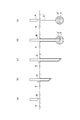
- generation apparatus which concerns on embodiment of this invention.
- generation apparatus shown in FIG. The figure which shows an example of operation
- generation apparatus (a) is a figure which shows the time at the time of filling with a drive liquid, (b) at the time of chemical
- generation apparatus (a) is a figure which shows at the time of pulse laser beam irradiation, and (b) at the time of filling with a drive liquid, respectively.
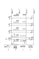
- Timing chart showing an example of the operation of the drug jet generating device (a) is a diagram showing the laser light intensity, (b) is a diagram showing the driving liquid delivery amount, (c) is a diagram showing the drug delivery amount, (d) Is a diagram showing the initial jet velocity (jet velocity).
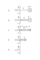
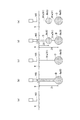
- generation apparatus (a) at the time of non-injection of a medicine, (b) at the time of medicine injection, (c) at the time of medicine arrival to an administration site, (d)
- medical agent administration by the injection needle of a comparative example (a) is the state before inserting the injection needle into the living body, (b) is the state where the injection needle is inserted into the living body, (c) is the drug administration site The state in which the tip of the injection needle has reached, (d) shows the time when the drug is administered, and (e) shows the time when the injection needle is removed.
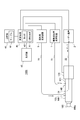
- BRIEF DESCRIPTION OF THE DRAWINGS The whole block diagram which shows an example of the chemical
- FIG. 8 is a timing chart showing an example of the operation of the medicine jet generating device shown in FIG. 8, (a) shows a laser beam intensity, (b) shows a driving liquid delivery amount, and (c) shows a medicine delivery amount.
- the figure which shows the position of an optical fiber, and (e) is a figure which shows a jet initial velocity (jet velocity).
- FIG. 8 is a diagram showing an example of the operation of the medicine jet generating device shown in FIG. 8, (a) before injection, (b) at the first injection, (c) at the first injection stop, and (d) at the first.
- (E) is a figure which respectively shows the time of the 2nd injection stop at the time of the 2nd injection.
- a drug jet generating device (also referred to as a jet generating device) according to an embodiment of the present invention has a light-absorbing liquid (also referred to as a driving liquid or a driving liquid) in a liquid chamber (capillary tube) having a nozzle at an end. ), A liquid chemical (chemical solution) is placed near the nozzle, and the drive liquid in the liquid chamber (capillary tube) is irradiated with laser light to generate vaporized gas. The medicine is ejected from the nozzle so that the liquid is moved toward the nozzle side at high speed and the driving liquid pushes out the medicine. At the time of laser beam irradiation, the laser beam is absorbed by the liquid and is not irradiated by the drug.
- generation apparatus can prevent the thermal denaturation and photochemical modification
- the solution sprayed by the jet generating device is not limited to the above drugs, and liquid media (liquid therapeutic media, treatments) containing genes, nucleic acids, cells, regenerated cell fluids, radioisotopes, etc. Solution, injection treatment solution, liquid injection substance, etc.).
- the jet generating device is used at the time of treatment, but is not limited to this form, for example, this jet generating device may be used at the time of diagnosis other than the treatment or under other circumstances, A jet generating device may be used as an auxiliary to some medical action.
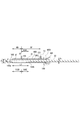
- a drug jet generating device 100 includes a liquid chamber 160, a laser device 2 (laser light source), a driving liquid feeding device 1, a drug feeding device 5, And a control device 4 (control unit).
- the control device 4 is communicably connected to each component via a wired communication path or a wireless communication path.
- the liquid chamber 160 is configured to hold the liquid F (driving liquid) and the medicine D therein.
- the liquid chamber 160 may have a grasping part grasped by the operator.
- the liquid chamber 160 (expansion chamber) is formed in a cylindrical shape.
- the liquid chamber 160 is formed in a cylindrical shape.
- the liquid chamber 160 is formed in a cylindrical shape having an outer diameter Po and an inner diameter Pz.
- the cylindrical liquid chamber 160 is formed of a material having high strength such as a metal material. Examples of a material for forming the liquid chamber 160 include metals such as stainless steel, titanium, gold, and silver, or materials such as ceramics.
- the inner diameter Pz of the metal thin tube as the liquid chamber 160 is about 0.5 mm to 3.0 mm, preferably about 1.0 mm.
- the liquid chamber 160 is connected to the driving liquid feeding device 1 via a tubular member 51 such as a feeding tube. Further, a filter (not shown) may be provided between the tubular member 51 and the liquid chamber 160.
- a laser device 2 (laser light source) is connected to one end of the liquid chamber 160 via an optical fiber 22.
- the optical fiber 22 is inserted into the liquid chamber 160, and the tip of the optical fiber 22 is disposed at a predetermined position in a metal thin tube that is a cylindrical liquid chamber 160.
- the liquid feeding device 1 for driving liquid supplies the liquid F (driving liquid) to the cylindrical liquid chamber 160 such as a metal cylindrical member via the tubular member 51 under the control of the control device 4 (control unit).
- the liquid F in the liquid chamber 160 include water, physiological saline, and electrolyte infusion.
- Laser device 2 (laser oscillator) as a laser light source generates pulsed laser light under the control of control device 4 (control unit).
- the pulsed laser light output from the laser device 2 is emitted into the cylindrical liquid chamber 160 from the laser light irradiation unit 21 at the tip of the optical fiber 22 through the optical fiber 22.
- the laser device 2 can independently control the laser light intensity and the laser light pulse width.
- the control device 4 controls the laser device 2 so as to change at least one of the laser energy, the pulse width, and the pulse repetition frequency of the pulsed laser light by the laser light irradiation unit 21.
- the laser device 2 can irradiate, for example, a pulsed laser beam having a maximum of about 1000 mJ per pulse.
- the laser device 2 include a holmium yag laser device (Ho: YAG laser: wavelength 2.1 ⁇ m), a thulium yag laser device (Tm: YAG laser: wavelength 2.01 ⁇ m), and a thulium fiber laser device (Tm fiber laser: wavelength). 2.01 ⁇ m) can be employed.
- the liquid F such as water, physiological saline, electrolyte infusion, or the like has the energy absorbability of the pulse laser beam from the laser device 2.
- the laser device 2 is not limited to the laser oscillator.
- the drug delivery device 5 supplies the drug D to the cylindrical liquid chamber 160 such as a metal cylindrical member via the tubular member 55 under the control of the control device 4 (control unit).
- the drug D is, for example, a liquid and desirably has non-absorbability with respect to laser light.
- various drugs such as anticancer agents, blood coagulation promoters, thrombolytic agents, anticoagulants, vasoconstrictors, genes, cells, and regenerative cell drugs can be employed.
- the drug D may be a drug in which a powder drug is dissolved in a solution.
- An opening-shaped nozzle 165 is formed at the end 160 a of the liquid chamber 160.
- the nozzle 165 is configured to be able to eject the medicine D injected into the liquid chamber 160 to the outside.
- the diameter Nz of the nozzle 165 is smaller than the inner diameter Pz of the cylindrical liquid chamber 160.
- the end of the tubular member 55 connected to the drug delivery device 5 is communicated with a drug introduction port 155 provided in the liquid chamber 160 of a metal thin tube.
- the tubular member 51 connected to the driving liquid delivery device 1 is communicated with a driving liquid inlet 151 provided in a liquid chamber 160 of a metal thin tube.
- the drug chamber 160 ⁇ / b> D and the expansion chamber 160 ⁇ / b> E are provided in communication between the nozzle 165 and the laser beam irradiation unit 21.
- the medicine chamber 160D is provided on the nozzle 165 side, and the expansion chamber 160E is provided on the laser light irradiation unit 21 side.
- the expansion chamber 160E is an area where the generated vaporized gas expands when the driving liquid is irradiated with laser light.
- the medicine chamber 160D is an area where the medicine D is supplied.
- the liquid chamber 160 (capillary tube) is provided with a drug introduction port 155 for supplying the drug D to the drug chamber 160D.
- the medicine introduction port 155 is provided between the nozzle 165 and the driving liquid introduction port 151.
- the laser beam irradiation unit 21 is disposed in the liquid chamber 160 between the drug introduction port 155 and the driving liquid introduction port 151.
- the distance ND between the nozzle 165 and the medicine introduction port 155 is shorter than the distance L1 between the nozzle 165 and the laser beam irradiation unit 21.
- the distance LD2 between the drug introduction port 155 and the laser light irradiation unit 21 is shorter than the distance DF between the drug introduction port 155 and the driving liquid introduction port 151.
- the distance L1 between the nozzle 165 and the laser light irradiation unit 21 is about 50 to 150 mm, and preferably about 100 mm.
- This distance L1 is set to a distance at which bubbles that are generated and expanded in the liquid chamber 160 by laser light irradiation are not outside the nozzle 165 formed at the end 160a of the liquid chamber 160.
- the inner diameters of the drug chamber 160D and the expansion chamber 160E of the liquid chamber 160 are about 1 mm, and the cross-sectional area is about 0.785 mm 2 . Since the jet flow generation device is configured to eject the drug D within one second from the time when the drug D is introduced into the drug chamber 160D, the jet liquid is transferred from the drug D to the driving liquid F or from the driving liquid F to the drug D. Diffusion is negligible. That is, the jet flow generating device 100 has a structure in which the medicine D and the driving liquid F are not mixed.
- a distance LD2 between the drug introduction port 155 and the laser beam irradiation unit 21 is defined as a distance at which the drug D is not thermally deteriorated by the laser beam.
- the distance LD2 is relatively short, the drug D is thermally deteriorated by the laser light.
- the distance LD2 is relatively long, the amount of the driving liquid F between the medicine D and the laser light irradiation unit 21 increases, and the driving liquid F has a large resistance force. As a result, the driving liquid F is pushed out by the expansion of bubbles. The force is weakened, and the jet velocity of the drug D is reduced.
- the distance LD2 is defined as a distance at which the drug D is not thermally deteriorated by the laser light and the jet velocity is equal to or higher than a specified value.
- the optical fiber 22 is inserted into the cylindrical liquid chamber 160 from the end opposite to the nozzle 165.
- the tip of the optical fiber 22 functions as a laser light irradiation unit 21.
- the liquid F in the liquid chamber 160 has energy absorbability with respect to the pulsed laser light emitted from the laser light irradiation unit 21.
- the high laser irradiation unit irradiates the liquid chamber 160 with pulsed laser light to heat and vaporize the liquid F.
- the diameter Az of the optical fiber 22 is smaller than the inner diameter Pz of the cylindrical liquid chamber 160.
- a gap is formed between the optical fiber 22 and the inner surface of the cylindrical liquid chamber 160, and the gap functions as the liquid supply path 140.
- the liquid F is supplied into the liquid chamber 160 through the liquid supply path 140.
- the optical fiber 22 is inserted into the liquid chamber 160 and a sealing member 169 such as an O-ring and a fixing member 168 disposed at the end 1601 (rear end) of the liquid chamber 160. It is fixed by.
- the inner surface of the cylindrical liquid chamber 160 has a mirror surface 160k that reflects the pulsed laser light emitted from the laser light irradiation unit 21.
- the pulse laser beam is reflected by the mirror surface 160k, the energy loss of the pulse laser beam is very small. For this reason, the pulsed laser light emitted from the laser light irradiation unit 21 is reflected directly and once or a plurality of times on the mirror surface 160k on the inner surface of the cylindrical liquid chamber 160, and the boundary surface of the bubble (gas-liquid interface) ).
- the boundary surface (gas-liquid interface) between the liquid F and the bubble here refers to the boundary surface (gas-liquid interface) on the opening side (nozzle 165 side) of the cylindrical liquid chamber 160 in the bubbles in the cylindrical liquid chamber 160. ).
- the mirror surface 160k is formed on the inner surface of the cylindrical liquid chamber 160 in the vicinity of the laser light irradiation unit 21 at the tip of the optical fiber 22 and in the whole or a part between the laser light irradiation unit 21 and the nozzle 165. Preferably it is formed.
- the mirror surface 160k is a surface processed by any one of electrolytic polishing processing, reamer processing processing, plating processing, vapor deposition processing, abrasive spraying processing, and the like. Specifically, when a metal thin tube such as stainless steel or titanium is employed as the cylindrical liquid chamber 160, the mirror surface 160k may be formed by optically polishing the inner surface of the metal thin tube. The mirror surface 160k may be formed by coating the inner surface of the metal thin tube with a material having a high reflectance with respect to the laser wavelength of the pulsed laser light. Specifically, the mirror surface 160k may be formed by coating the inner surface of the metal thin tube with gold or performing gold plating.
- the mirror surface 160k may be formed by press-fitting a thin thin tube (gold), which is a highly reflective material, into a metal thin tube.
- a thin thin tube gold
- the abrasive spraying process include a process of spraying fine particles (fine resin particles or the like) to which the abrasive is attached into the cylindrical liquid chamber 160 at a high speed.
- the mirror surface 160k on the inner surface of the liquid chamber 160 has a reflectance of a specified value or more with respect to the pulsed laser light irradiated by the laser light irradiation unit 21.
- the medicine jet generating device 100 can inject the medicine D at several pulses per second. In the initial state, the drug jet generating device 100 does not irradiate laser light.
- the inside of the liquid chamber 160 is cleaned by filling the liquid chamber 160 with the new driving liquid F and replacing the old driving liquid F with the new driving liquid F.
- the control device 4 controls the driving liquid feeding device 1 so as to fill the liquid chamber 160 with the liquid F (driving liquid).
- a process of feeding the liquid F is performed. As shown in FIG. 3A, the liquid chamber 160 is filled with the liquid F (driving liquid).
- step ST ⁇ b> 2 shown in FIG. 5C the control device 4 (control unit) controls the drug delivery device 5 to send the set amount DV ⁇ b> 1 of drug D to the drug chamber 160 ⁇ / b> D of the liquid chamber 160.
- the control device 4 controls the drug delivery device 5 to send the set amount DV ⁇ b> 1 of drug D to the drug chamber 160 ⁇ / b> D of the liquid chamber 160.
- Perform a liquid treatment Specifically, as shown in FIG. 3B, the medicine D flows from the medicine feeding device 5 into the medicine chamber 160 ⁇ / b> D of the liquid chamber 160 through the tubular member 55 and the medicine introduction port 155.
- step ST3 shown in FIG. 5 (b) the control device 4 (control unit) controls the driving liquid feeding device 1 to feed the liquid F (driving liquid) into the liquid chamber 160.
- the drug D is moved to the nozzle 165 side by the driving liquid F.
- the control device 4 determines the amount of the driving liquid F according to the amount of the medicine D.
- step ST4 shown in FIG. 5A the control device 4 (control unit) irradiates the laser beam with the laser device 2 based on the set laser energy (laser beam intensity and laser pulse width). I do.
- the laser beam intensity is set to Ia
- the laser pulse width is set to Tla.
- a jet of the medicine D is discharged from the nozzle 165 (see FIG. 4A).
- the initial velocity of the jet is Va
- the medicine D is discharged for a predetermined time corresponding to the laser pulse width (Tla).
- the liquid F (driving liquid) in the vicinity of the laser light irradiation unit 21 is heated and vaporized by the pulsed laser light emitted from the laser light irradiation unit 21, and the liquid F is expanded by the expansion of the vaporized gas G (bubbles).
- the medicine D is pressurized toward the nozzle 165 side, the medicine D is pushed out by the liquid F, and the medicine D is ejected from the nozzle 165.
- step ST6 shown in FIG. 5B the control device 4 (control unit) controls the driving liquid feeding device 1 so as to fill the liquid chamber 160 with the liquid F (driving liquid).
- step ST6 controls the driving liquid feeding device 1 so as to fill the liquid chamber 160 with the liquid F (driving liquid).
- a process of feeding the liquid F is performed.
- the liquid chamber 160 is filled with the liquid F (driving liquid).
- step ST7 shown in FIG.5 (c) the control apparatus 4 (control part) controls the liquid delivery apparatus 5 for chemical
- FIG. The medicine D flows into the liquid chamber 160 from the medicine liquid feeding device 5 through the tubular member 55 and the medicine introduction port 155.
- step ST8 shown in FIG. 5 (b) the control device 4 (control unit) controls the driving liquid feeding device 1 to feed the liquid F (driving liquid) to the liquid chamber 160.
- the drug D moves to the nozzle 165 side by the driving liquid F.
- the control device 4 determines the amount of the driving liquid F according to the amount of the medicine D.
- the drug jet generating apparatus 100 repeats the operations of steps ST4 to ST8 a predetermined number of times at a set frequency based on the set laser beam intensity (power) and the laser beam pulse width.
- the medicine jet generating device 100 can inject the pulsed liquid medicine D a predetermined number of times in a short time.
- the drug jet generating device 100 may spray a single pulsed liquid drug D.
- the nozzle 165 of the drug jet generating device 100 is disposed in the vicinity of the administration site of the body tissue 9 when the drug D is not jetted. At this time, the nozzle 165 is arranged so that the injection direction of the medicine D from the nozzle 165 faces the administration site.
- the medicine D is ejected from the nozzle 165.
- the jet of the drug D has a perforating action on the body tissue 9, and a hole is formed from the surface of the body tissue 9 to the inside of the body tissue 9.
- the depth of the perforations can be controlled by the jet strength.
- the kinetic energy of the jet of the drug D decreases, and as shown in FIG. 6 (c), a hole is formed to a depth Z1 corresponding to the strength of the jet.
- the intensity of the jet is proportional to the output (energy) P1 of the pulse laser beam.
- the pressure of the drug D in the jet is concentrated and diffused in a portion of the body tissue 9 where the mechanical strength is weak.
- the drug D is also diffused during the perforation. For this reason, the drug D can also be diffused into the body tissue 9 in the vicinity of the hole mark 91.
- FIGS. 7 (a) to 7 (e) an example of an operation for administering the drug D by the injection needle will be described.
- the distal end portion of the injection needle N is pierced to the administration site at the deep position of the body tissue 9.
- the drug D is not administered.
- the drug D is administered from the tip of the injection needle N.
- a liquid reservoir 8 'of the drug D is formed at the administration site.
- the drug D since the drug D is not administered while the injection needle N is being pierced, the drug D does not diffuse into the body tissue near the trace 91 'through the hole through which the injection needle has passed.
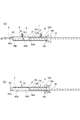
- the medicine jet generating device 100b can independently control the injection speed and the injection time of the medicine D injected from the nozzle 165. Further, the medicine jet generation device 100b determines the distance L1, the laser light intensity (power), and the laser light pulse width between the nozzle 165 and the laser light irradiation unit 21 according to the set injection speed and time of the medicine D. And adjusting means for automatically adjusting the timing of introducing the drug D into the liquid chamber and the amount of the drug D, the timing of introducing the driving liquid F into the liquid chamber 160 and the amount of the driving liquid F, and the like.
- the drug jet generating device 100b includes a liquid chamber 160 (expansion chamber), a laser device 2 (laser light source), a fiber driving device 170, a driving liquid feeding device 1, a drug feeding device 5, and a setting unit 45. , Control device 4b (control unit), and the like.
- the control device 4b is communicably connected to each component via a wired communication path or a wireless communication path.
- the setting unit 45 is configured by an operation input device such as an operation button or a touch panel, and sets the set values of the injection speed (jet initial speed) and the injection time of the medicine D according to the operation of the operator.
- the storage unit 46 includes a storage device such as a RAM, a ROM, an HDD, and an SSD.
- the storage unit 46 stores a table 47, a control program, and the like.
- the table 47 of the storage unit 46 includes, for example, a distance L1 between the nozzle 165 and the laser light irradiation unit 21, a set value of the injection speed (jet flow initial speed) and injection time of the medicine D, laser light intensity (power), and laser light.
- the pulse width, the timing of introducing the drug D into the liquid chamber 160 and the amount of the drug D, the timing of introducing the driving liquid F into the liquid chamber 160 and the amount of the driving liquid F are stored in association with each other in advance.
- the control device 4b (control unit) implements the function according to the embodiment of the present invention in the control device (computer) by executing the control program.
- the control device 4b includes a reading unit 40, an automatic control unit 41, and the like.
- the reading unit 40 refers to the table 47 of the storage unit 46, and corresponds to the nozzle 165 and the laser beam irradiation unit 21 corresponding to the setting values of the injection speed (jet flow initial speed) and the injection time of the medicine D set by the setting unit 45. , Information indicating the distance between them, laser light intensity (power) and laser light pulse width, timing of introducing the drug D into the liquid chamber 160 and amount of the drug D, timing of introducing the driving liquid F into the liquid chamber 160 and driving The amount of the liquid F is read from the storage unit 46 regarding the pulse laser beam intensity and the laser beam pulse width.
- the automatic control unit 41 of the control device 4b performs a process of outputting to the laser device 2 a laser output control signal corresponding to the information on the pulse laser beam intensity and the laser beam pulse width read from the storage unit 46 by the reading unit 40. Do. Based on the laser output control signal, the laser device 2 outputs a pulse laser beam having a pulse laser beam intensity and a laser beam pulse width at a predetermined timing.
- the automatic control unit 41 outputs a fiber drive control signal, which is read from the storage unit 46 by the reading unit 40 and indicates information indicating the distance between the nozzle 165 and the laser light irradiation unit 21, to the fiber drive device 170. Perform the process.
- the fiber drive device 170 sets the distance between the nozzle 165 and the laser light irradiation unit 21 based on the fiber drive control signal.
- the automatic control unit 41 outputs a liquid feeding control signal, which is read from the storage unit 46 by the reading unit 40 and indicates the timing of the driving liquid F and the amount of the driving liquid F, to the driving liquid feeding device 1. I do.
- the driving liquid feeding device 1 automatically adjusts the timing of introducing the liquid F (driving liquid) from the driving liquid feeding device 1 into the liquid chamber 160 and the amount of the driving liquid F based on the liquid feeding control signal. .
- the automatic control unit 41 performs a process of outputting the control signal indicating the timing of the driving liquid F and the amount of the driving liquid F read from the storage unit 46 by the reading unit 40 to the liquid delivery device 5 for medicine.
- the drug delivery device 5 automatically adjusts the timing of introducing the drug D from the drug delivery device 5 into the liquid chamber 160 and the amount of the drug D based on the control signal.
- the fiber driving device 170 sets the distance between the nozzle 165 and the laser light irradiation unit 21 under the control of the control device 4b.
- the fiber driving device 170 includes an O-ring sealing member 1709 and a fixing member 1603 at the end 1602 (rear end) of the liquid chamber 160. It is fixed.
- the end 1602 of the liquid chamber 160 and the fixing member 1603 are configured to be screwed together by screwing portions 1602a and 1603a.
- the fiber driving device 170 is provided with a motor 1702.
- a motor 1702 various motors such as a DC motor and an AC motor can be employed.
- a rotor 1703 of the motor 1702 has a cylindrical portion extending rearward from the motor flange 1701, and a movable member 1704 and a movable member 1705 that are movable in the axial direction are accommodated inside the cylindrical portion. is doing.
- a cylindrical movable member 1704 and a movable member 1705 arranged around the optical fiber 22 are screwed together by screwing portions 1704b and 1705a in a state where a sealing member 1708 such as an O-ring is accommodated therein, The optical fiber 22 is supported and fixed.
- the cylindrical movable member 1704 has a hole portion through which a guide portion 1701b extending rearward from the motor flange 1701 passes, and is configured to be movable along the guide portion 1701b.
- the movable member 1704 and the rotor 1703 of the motor 1702 are screwed together by screwing portions 1704a and 1703a.
- the cylindrical movable member 1704 and the optical fiber 22 supported by the movable member 1705 are configured to be movable in the axial direction. That is, the fiber driving device 170 rotates the rotor 1703 of the motor 1702 under the control of the control device 4b, so that the distance between the nozzle 165 and the laser beam irradiation unit 21 provided at the tip of the optical fiber 22 is increased.
- L1 is configured to be adjustable.
- the expansion chamber as the liquid chamber 160 is configured by a thin tube, and the vaporized gas generated by the irradiation of the pulsed laser light expands toward the nozzle 165 from the optical fiber emission point (laser light irradiation unit 21) in the narrow tube.
- the ejection of vaporized gas is dangerous because it is a high temperature and high pressure, and the nozzle 165 side gas-liquid interface (boundary surface FG) needs to stay in the liquid chamber 160 (fine tube) reliably.
- the gap between the nozzle 165 side gas-liquid interface (boundary surface FG) and the laser light irradiation unit 21 is reduced. Is made smaller than G1.
- the fluid resistance in the narrow tube is proportional to the contact area (area in the narrow tube) between the liquid F in the liquid chamber 160 (thin tube) and the inner peripheral surface of the narrow tube.
- the inside area of the narrow tube is proportional to the diameter of the thin tube and the distance between the nozzle 165 and the boundary surface FG.
- the volume of the liquid F in the narrow tube is proportional to the square of the thin tube radius and the distance between the nozzle 165 and the boundary surface FG. Therefore, when a certain amount of liquid F is to be ejected from the nozzle 165, if the diameter of the thin tube is reduced, the distance between the nozzle 165 and the boundary surface FG must be increased accordingly, and the fluid resistance is increased. turn into. As described above, in order to efficiently generate a jet corresponding to the change of the laser energy, it is necessary to maintain W1 regardless of the laser energy.
- the output point (laser beam irradiation part 21) of the optical fiber 22 is comprised so that a movement is possible according to laser energy (FIG. 9 (a), FIG. 9). (See (b)).
- the control device 4b includes the laser device 2, the liquid feeding device 1 for driving liquid (liquid feeding pump). ), A process of controlling the drug delivery device 5 and the fiber driving device 170 is performed.
- step ST ⁇ b> 11 shown in FIG. 10D the reading unit 40 of the control device 4 b responds to the injection speed (jet initial speed) of the drug D and the injection time of the drug D set by the setting unit 45.
- Information indicating the distance between the nozzle 165 and the laser light irradiation unit 21 corresponding to the injection speed (jet initial speed) of the drug D and the injection time of the drug D from the table 47 stored in the storage unit 46, laser light The intensity (power), the laser light pulse width, the timing of introducing the drug D into the liquid chamber 160 and the amount of the drug D, the timing of introducing the driving liquid F into the liquid chamber 160 and the amount of the driving liquid F are read from the storage unit 46.
- the automatic control unit 41 outputs a fiber drive control signal including information indicating the distance L1 between the nozzle 165 and the laser light irradiation unit 21 read from the storage unit 46 by the reading unit 40 to the fiber drive device 170.
- the fiber driving device 170 automatically adjusts the distance between the nozzle 165 and the laser light irradiation unit 21 so as to be a distance determined based on the setting value and the table by the fiber driving control signal.
- the control device 4b performs a process of moving and fixing the optical fiber emitting end (laser light irradiation unit 21) to the position corresponding to the laser energy by the fiber driving device 170c. That is, the laser beam irradiation unit 21 is set at a distance La from the nozzle 165.
- step ST12 shown in FIG. 10B the control device 4b performs a process of sending the liquid F to the liquid chamber 160 (expansion chamber) and filling the liquid chamber 160 with the liquid F by the driving liquid feeding device 1. .
- step ST13 shown in FIG. 10 (c) the control device 4b performs a process of sending a predetermined amount of the medicine D set to the liquid chamber 160 by the medicine liquid feeding device 5 (liquid feeding pump).
- step ST14 shown in FIG. 10B the control device 4b controls the driving liquid feeding device 1 to feed the liquid F (driving liquid) into the liquid chamber 160.
- the drug D moves to the nozzle 165 side by the driving liquid F.
- the control device 4 determines the amount of the driving liquid F according to the amount of the medicine D.
- step ST16 shown in FIG. 10 (e) the jet of the medicine D is emitted from the nozzle 165.
- the drug D is emitted such that the initial jet velocity (jet velocity) is Va and the injection time of the drug D is TDa.
- the liquid F (driving liquid) in the vicinity of the laser light irradiation unit 21 is heated and vaporized by the pulsed laser light emitted from the laser light irradiation unit 21, and the liquid F is expanded by the expansion of the vaporized gas G (bubbles).
- the medicine D is pressurized toward the nozzle 165 side, the medicine D is pushed out by the liquid F, and the medicine D is ejected from the nozzle 165.
- step ST17 shown in FIG. 10D the control device 4b emits the optical fiber at a position corresponding to the next laser energy (low laser beam intensity (power) (Ia) ⁇ large laser beam pulse width (Tlb)).
- a process of moving and fixing the end (laser light irradiation unit 21) by the fiber driving device 170 is performed. Specifically, the laser beam irradiation unit 21 is set at a position at a distance Lb from the nozzle 165.
- step ST18 shown in FIG. 10 (b) the control device 4b calculates the pre-injection jet flow rate and the volume change amount accompanying the fiber movement, and the liquid chamber 160 is driven by the liquid supply device 1 (liquid feed pump) for driving liquid.
- An appropriate amount of the liquid F (driving liquid) is sent to the (expansion chamber), and the liquid chamber 160 is filled with the liquid F (driving liquid).
- step ST19 shown in FIG. 10 (c) the control device 4b performs a process of sending a predetermined amount of medicine D set to the liquid chamber 160 by the medicine liquid delivery device 5 (liquid feed pump).
- step ST20 shown in FIG. 10B the control device 4b (control unit) controls the driving liquid feeding device 1 to send the liquid F (driving liquid) to the liquid chamber 160.
- the drug D moves to the nozzle 165 side by the driving liquid F.
- the control device 4b determines the amount of the driving liquid F according to the amount of the medicine D.
- steps ST15 to ST20 are performed as follows.
- the injection speed of the drug D initial jet velocity
- the injection time of the drug D is small (Va )
- Vb injection speed of the medicine D
- TDa injection time of the medicine D
- Vb injection speed of the medicine D
- TDb injection time of the medicine D
- the nozzle 165 of the drug jet generating device 100b is arranged in the vicinity of the administration site of the body tissue 9 when the drug D is not jetted. At this time, the nozzle 165 is arranged so that the injection direction of the medicine D from the nozzle 165 faces the administration site.
- a set amount DV1 of the drug D is supplied to the drug room. Pulse laser light is output from the laser light irradiation unit 21. The laser output (energy) is P1.
- the liquid F (driving liquid) in the vicinity of the laser light irradiation unit 21 is heated and vaporized, the liquid F pressurizes the drug D toward the nozzle 165 due to the expansion of the vaporized gas G (bubbles), and the drug F is pushed out by the liquid F. As shown in FIG. 11B, the medicine D is ejected from the nozzle 165.
- a hole is formed from the surface of the body tissue 9 to the inside of the body tissue 9 by the jet of the drug D.
- the depth of the perforations can be controlled by the jet strength. Then, as the drilling proceeds, the kinetic energy of the jet of the drug D decreases, and a hole is formed to a depth Z1 corresponding to the strength of the jet.
- the intensity of the jet is proportional to the output (energy) P1 of the pulse laser beam.
- the set amount DV2 of the drug D is supplied to the drug room.
- DV2 ⁇ DV1 is set.
- the driving liquid F is supplied to the liquid chamber 160, and the medicine D is moved to the nozzle side by the driving liquid F.
- the supply amount of the driving liquid F is determined according to the amount of the medicine D supplied to the medicine chamber 160D.
- a pulse laser beam is output from the laser beam irradiation unit 21.
- the output (energy) of the laser is P2.
- the liquid F (driving liquid) in the vicinity of the laser light irradiation unit 21 is heated and vaporized, the liquid F pressurizes the drug D toward the nozzle 165 due to the expansion of the vaporized gas G (bubbles), and the drug F is pushed out by the liquid F.
- the medicine D is ejected from the nozzle 165.
- a liquid reservoir 8b (8) of the medicine D is formed at a depth Z2 corresponding to the output (energy) P2 of the laser beam.
- liquid reservoirs 8 a (8) and 8 b (8) of the drug D are maintained in that state for a predetermined time and then slowly diffused into the body tissue 9.
- the liquid reservoir of the drug D can be easily formed at arbitrary positions with different depths in the body tissue 9.
- the drug jet generating device 100b forms a plurality of liquid pools in the depth direction (Z-axis direction) of the body tissue, but is not limited to this form.
- the drug jet generating device arranges a plurality of nozzles one-dimensionally in a predetermined direction (X-axis direction) at a predetermined interval, thereby allowing a predetermined depth of body tissue in the Z-axis direction at a predetermined interval in the X-axis direction.
- the liquid reservoir of the medicine D can be easily formed at this position.
- the medicine jet generating device arranges a plurality of nozzles two-dimensionally at predetermined intervals in the X-axis direction and the Y-axis direction, so that the liquid reservoir of the medicine D is predetermined in the X-axis direction and the Y-axis direction. It is possible to distribute three-dimensionally at predetermined intervals and at predetermined positions in the Z-axis direction (positions having a predetermined depth of the body tissue).
- control device (control unit) of the drug jet generating device can easily define the amount of each drug D formed in the body tissue by controlling the amount of the drug D to be supplied. .
- the drug jet generating devices 100 and 100b include the cylindrical liquid chamber 160 (expansion chamber), the nozzle 165 formed at the end of the liquid chamber 160, and the liquid.
- the liquid supply device 1 for driving liquid that supplies the driving liquid F (driving liquid) into the chamber 160 via the tubular member 51, and the drug D is supplied to the vicinity of the nozzle 165 in the liquid chamber 160 via the tubular member 55.
- the liquid delivery device 5 for medicine and the liquid chamber 160 are irradiated with pulsed laser light to vaporize the driving liquid F in the liquid chamber 160, and the medicine D is supplied to the nozzle 165 via the driving liquid F.
- a laser light source laser device 2 that generates pulsed laser light.
- the liquid chamber 160 is disposed on the nozzle 165 side of the driving liquid introduction port 151 for introducing the driving liquid F supplied from the driving liquid feeding apparatus 1 into the liquid chamber 160, and the driving liquid introduction port 151.
- a medicine introduction port 155 for introducing the medicine D supplied from the medicine liquid feeding device 5 into the liquid chamber 160 is provided.
- the laser light irradiation unit 21 is disposed between the drive liquid inlet 151 and the medicine inlet 155.
- the driving liquid feeding device 1 supplies the driving liquid F into the liquid chamber 160
- the drug feeding device 5 supplies the drug D near the nozzle 165 in the liquid chamber 160
- a laser beam irradiation unit. 21 irradiates the driving liquid F in the liquid chamber 160 (capillary tube) with laser light to generate vaporized gas. Due to the expansion of the vaporized gas, the driving liquid F is moved at high speed toward the nozzle 165 side, and the drug D is ejected from the nozzle 165 so that the driving liquid F pushes out the drug D.
- the drug jet generating devices 100 and 100b that can jet the drug D at a high speed and allow the drug D to reach a deep position in the body tissue. That is, it is possible to provide the drug jet generating devices 100 and 100b that can be locally administered without using a needle and have high efficiency of drug introduction to the target.
- the drug jet generating method of the drug jet generating devices 100 and 100b can be provided.
- the driving liquid F has a wavelength band with good absorbability as the wavelength of the laser light, the laser light is absorbed by the driving liquid F and is not irradiated to the drug D when the laser light is irradiated. Thermal degradation is suppressed. Further, the heat transfer to the drug D due to the heat conduction during the expansion of the vaporized gas is as short as several milliseconds from the laser irradiation to the jet injection, and therefore, the driving liquid F between the vaporized gas and the drug D is short. It is interrupted by.
- the drug jet generating devices 100 and 100b can be easily used for an operation using an endoscope or a microscope with a narrow surgical field. Can be used for
- the drug jet generating devices 100 and 100b according to the embodiment of the present invention have the narrow tube (diameter) liquid chamber 160 (expansion chamber), the drug D and the driving liquid F are not easily mixed. .
- the laser beam irradiation unit 21 of the drug jet generating devices 100 and 100b according to the embodiment of the present invention is disposed between the driving liquid inlet 151 and the drug inlet 155, and with respect to the drug D in the liquid chamber 160. Therefore, it is placed at a position that is not affected by the thermal effect of the pulse laser beam. For this reason, the chemical
- the laser apparatus 2 (laser light source) of the chemical
- the medicine jet generating device 100b is configured to set the laser light intensity and the laser light pulse width, and the nozzle 165 and the laser according to one or both of the injection speed and the injection time of the medicine D set by the setting unit 45.
- Adjustment means control device 4b, fiber driving device 170 for automatically adjusting the distance to the light irradiation unit 21 is provided. For this reason, according to the injection speed and injection time of the medicine D set by the setting unit 45, the medicine jet generating device 100b that can inject the medicine D can be provided.
- the drug jet generation devices 100 and 100b optimally adjust the injection speed of the drug D, so that the difference in composition of body tissues (difference in elastic modulus, coupling rate between body tissues
- the drug D can selectively reach a deep position (about 1 mm to 20 cm) of the body tissue without damaging the necessary body tissue.
- the drug jet generating devices 100 and 100b can jet the drug D from the nozzle continuously in a short time in a pulse shape. For example, by injecting a plurality of times toward the deep part of the body tissue in a short time, the drug D can easily reach a deep position of the body tissue as compared with a case of single injection.
- the drug jet generating devices 100 and 100b include the above-described drug jet mode for jetting the drug D and the liquid jet mode (the liquid jet without filling the drug chamber 160 with the drug D). And a mode for performing an operation such as an incision).
- generation apparatuses 100 and 100b 4 adjusts the position of the laser beam irradiation part 21 automatically according to chemical
- the drug jet generating devices 100 and 100b may have a suction device.
- the drug jet generation devices 100 and 100b may have suction pipes provided coaxially on the outer peripheral side of the cylindrical liquid chamber 160.
- the drug jet generating devices 100 and 100b can suck the extra drug D and liquid F (driving liquid) with a suction device as necessary.
- the drug jet generating device according to the present invention may be applied to a medical device such as a surgical operation robot.
- This surgery support robot includes an arm equipped with a drug jet generation device and an endoscope camera, and is configured to perform a predetermined surgery by remote operation by an operator's operation device.
Abstract
Provided is a drug jet generation device capable of spraying a drug at a high speed and delivering the drug to a deep-tissue site while suppressing the thermal degradation of the drug. A drug jet generation device (100, 100b) comprises: a tubular liquid chamber (160); a nozzle (165) formed at an end of the liquid chamber (160); a driving liquid feed device (1) that supplies a driving liquid into the interior of the liquid chamber (160); a drug feed device (5) that supplies a drug in the vicinity of the nozzle (165) on the interior of the liquid chamber (160); a laser light irradiation unit (21) that irradiates the interior of the liquid chamber (160) with pulsed laser light, vaporizes the driving liquid on the interior of the liquid chamber (160), and sprays the drug from the nozzle (165) by means of the driving liquid; and a laser light source (2) that generates pulsed laser light. The liquid chamber (160) comprises a driving liquid introduction port (151) through which the driving liquid supplied from the driving liquid feed device (1) is introduced into the interior of the liquid chamber (160), and a drug introduction port (155) which is positioned further towards the nozzle (165) side than the driving liquid introduction port (151) and through which the drug supplied from the drug feed device (5) is introduced into the interior of the liquid chamber (160). The laser light irradiation unit (21) is disposed between the driving liquid introduction port (151) and the drug introduction port (155).
Description
本発明は、薬剤噴流生成装置、及び薬剤噴流生成装置の薬剤噴流生成方法に関するものである。
The present invention relates to a drug jet generating device and a drug jet generating method of the drug jet generating device.
光ファイバーがチューブ内に挿入され、レーザー発振器から光ファイバーを介して出射されたレーザー光により、チューブ内に充填された水などの液体を急激に加熱して液体噴流(液体ジェット)を発生させ、この液体噴流の力により血栓などを破砕し除去する手術用器具(パルスジェットメス)が知られている(例えば、特許文献1参照)。
An optical fiber is inserted into the tube, and a liquid jet (liquid jet) is generated by rapidly heating a liquid such as water filled in the tube by laser light emitted from the laser oscillator through the optical fiber. A surgical instrument (pulse jet knife) that crushes and removes a thrombus or the like by the force of a jet is known (see, for example, Patent Document 1).
詳細には、特許文献1に記載のレーザー誘起液体噴流発生デバイスは、光ファイバーの先端部に形成されたレーザー照射部を内部に収容し、液体噴流を生じさせるジェット発生管部を有する。このレーザー誘起液体噴流発生デバイスは、Yコネクター及びYコネクターをレーザー発振器に連結する連結部材を有し、連結部材はレーザー発振器から突設された連結突部と螺合されるスリーブ部材を備え、レーザー発振器とYコネクターが脱着可能に連結している。Yコネクターの所定のポートには光ファイバーが挿通され、光ファイバーを樹脂などの固定部材によりスリーブ部材に一体的に固定した構造となっている。
Specifically, the laser-induced liquid jet generating device described in Patent Document 1 has a jet generating tube portion that accommodates a laser irradiation portion formed at the tip of an optical fiber and generates a liquid jet. This laser-induced liquid jet generating device has a Y connector and a connecting member that connects the Y connector to a laser oscillator, and the connecting member includes a sleeve member that is screwed with a connecting protrusion protruding from the laser oscillator. The oscillator and the Y connector are detachably connected. An optical fiber is inserted into a predetermined port of the Y connector, and the optical fiber is integrally fixed to the sleeve member by a fixing member such as a resin.
ところで、薬剤などを生体に投与したい場合がある。詳細には、術中に、薬剤として、抗癌剤、血液凝固促進剤、血栓溶解剤、抗凝固剤、血管収縮剤などや、遺伝子、細胞、再生細胞薬などを生体に投与したい場合がある。
By the way, there are cases where it is desired to administer drugs or the like to a living body. Specifically, there are cases where it is desired to administer anticancer agents, blood coagulation promoters, thrombolytic agents, anticoagulants, vasoconstrictors, etc., genes, cells, regenerative cell drugs, etc. as living drugs during surgery.
薬剤投与の方法としては、脈管経由による投与方法、穿刺針(注射針)による対象部位への直接投与法などが知られている。
As a method for administering a drug, an administration method via a blood vessel, a direct administration method to a target site with a puncture needle (injection needle), and the like are known.
しかしながら、脈管経由による注射針を用いた投与方法では、比較的大量の薬剤を要する。また、脈管経由で薬剤が投与されるため、対象部位以外の部分(全身など)で意図しない副作用が生じる虞がある。
However, the administration method using an injection needle via a blood vessel requires a relatively large amount of drug. In addition, since the drug is administered via the blood vessel, an unintended side effect may occur in a portion other than the target site (such as the whole body).
穿刺針による対象部位への直接投与法では薬剤を限局投与することができ、対象部位以外の部分における副作用が少ない。しかしながら、穿刺針を用いた直接投与法では、対象部位への薬剤の到達率が比較的小さい、注射針で体組織が傷つく、などの虞がある。
The direct administration method to the target site with a puncture needle allows the drug to be administered locally, and there are few side effects in parts other than the target site. However, in the direct administration method using a puncture needle, there is a risk that the arrival rate of the drug at the target site is relatively small, or the body tissue is damaged by the injection needle.
また、例えば、特許文献1に記載のレーザー誘起噴流発生デバイスにおいて、単純に、薬剤を液体に溶解させて、その液体にレーザー光を照射させた場合、薬剤がレーザー光の照射により熱劣化する、薬剤と液体の混合により薬剤が希釈して変質する、などの虞がある。
In addition, for example, in the laser-induced jet generation device described in Patent Document 1, when a drug is simply dissolved in a liquid and the liquid is irradiated with laser light, the drug is thermally deteriorated by irradiation with the laser light. There is a possibility that the drug is diluted and deteriorated by mixing the drug and the liquid.
また、例えば、高圧ポンプを用いて液体の連続流ジェットを噴射する連続流ジェット噴射装置にて、薬剤を溶解させた液体の連続流ジェットを噴射させた場合、大量の薬剤を要する、薬剤投与量をコントロールできない、などの問題がある。
In addition, for example, when a continuous flow jet in which a liquid is dissolved is injected in a continuous flow jet injection apparatus that injects a continuous flow jet of liquid using a high-pressure pump, a large amount of drug is required. There are problems such as inability to control.
また、内視鏡や顕微鏡を用いた手術では、術野が非常に狭く、大型の手術器具を使用することができないという問題がある。
Also, surgery using an endoscope or a microscope has a problem that the surgical field is very narrow and a large surgical instrument cannot be used.
本発明の薬剤噴流生成装置は、以下の構成を少なくとも具備するものである。
薬剤を噴射する薬剤噴流生成装置であって、
筒状の液体室と、
前記液体室の端部に形成されたノズルと、
前記液体室内に駆動用の液体を供給する駆動液体用送液装置と、
前記液体室内のノズル付近に薬剤を供給する薬剤用送液装置と、
前記液体室内にパルスレーザー光を照射して、該液体室内の駆動用の液体を気化させ、前記薬剤を駆動用の液体を介して前記ノズルから噴射させるレーザー光照射部と、
前記パルスレーザー光を発生するレーザー光源と、を有し、
前記液体室は、前記駆動液体用送液装置から供給される前記駆動用の液体を前記液体室内に導入する駆動液体導入口と、前記駆動液体導入口よりもノズル側に配置され、前記薬剤用送液装置から供給される前記薬剤を前記液体室内に導入する薬剤導入口とを備え、
前記レーザー光照射部は、前記駆動液体導入口と前記薬剤導入口との間に配置されていることを特徴とする。 The drug jet generating device of the present invention has at least the following configuration.
A drug jet generating device for jetting a drug,
A cylindrical liquid chamber;
A nozzle formed at an end of the liquid chamber;
A liquid supply device for driving liquid for supplying a liquid for driving into the liquid chamber;
A drug delivery device for supplying a drug near the nozzle in the liquid chamber;
A laser beam irradiation unit configured to irradiate the liquid chamber with a pulsed laser beam, vaporize the driving liquid in the liquid chamber, and eject the medicine from the nozzle through the driving liquid;
A laser light source for generating the pulsed laser light,
The liquid chamber is disposed on the nozzle side of the driving liquid introduction port for introducing the driving liquid supplied from the driving liquid feeding device into the liquid chamber, and for the medicine. A drug introduction port for introducing the drug supplied from the liquid feeding device into the liquid chamber;
The laser light irradiation unit is arranged between the driving liquid introduction port and the drug introduction port.
また、本発明の薬剤噴流生成装置の薬剤噴流生成方法は、以下の構成を少なくとも具備するものである。
薬剤を噴射する薬剤噴流生成装置の薬剤噴流生成方法であって、
薬剤噴流生成装置は、
筒状の液体室と、
前記液体室の端部に形成されたノズルと、
前記液体室内に駆動用の液体を供給する駆動液体用送液装置と、
前記液体室内の前記ノズル付近に薬剤を供給する薬剤用送液装置と、
前記液体室内にパルスレーザー光を照射して、該液体室内の駆動用の液体を気化させ、前記薬剤を駆動用の液体を介して前記ノズルから噴射させるレーザー光照射部と、
前記パルスレーザー光を発生するレーザー光源と、を有し、
前記液体室は、前記駆動液体用送液装置から供給される前記駆動用の液体を前記液体室内に導入する駆動液体導入口と、前記駆動液体導入口よりもノズル側に配置され、前記薬剤用送液装置から供給される前記薬剤を前記液体室内に導入する薬剤導入口とを備え、
前記レーザー光照射部は、前記駆動液体導入口と前記薬剤導入口との間に配置され、
前記駆動液体用送液装置が、前記液体室内に駆動用の液体を供給するステップと、
前記薬剤用送液装置が、前記液体室内の前記ノズル付近に薬剤を供給するステップと、
前記レーザー光照射部が前記液体室内にパルスレーザー光を照射して、該液体室内の駆動用の液体を気化させ、前記薬剤を駆動用の液体を介して前記ノズルから噴射させるステップと、を有することを特徴とする。 Moreover, the chemical | medical agent jet production | generation method of the chemical | medical agent jet production | generation apparatus of this invention comprises at least the following structures.
A drug jet generating method of a drug jet generating device for injecting a drug,
The drug jet generator
A cylindrical liquid chamber;
A nozzle formed at an end of the liquid chamber;
A liquid supply device for driving liquid for supplying a liquid for driving into the liquid chamber;
A drug delivery device for supplying a drug to the vicinity of the nozzle in the liquid chamber;
A laser beam irradiation unit configured to irradiate the liquid chamber with a pulsed laser beam, vaporize the driving liquid in the liquid chamber, and eject the medicine from the nozzle through the driving liquid;
A laser light source for generating the pulsed laser light,
The liquid chamber is disposed on the nozzle side of the driving liquid introduction port for introducing the driving liquid supplied from the driving liquid feeding device into the liquid chamber, and for the medicine. A drug introduction port for introducing the drug supplied from the liquid feeding device into the liquid chamber;
The laser beam irradiation unit is disposed between the driving liquid inlet and the drug inlet,
The driving liquid feeding device supplying a driving liquid into the liquid chamber;
The liquid feeding device for medicine supplies a medicine near the nozzle in the liquid chamber;
The laser light irradiation unit irradiating the liquid chamber with pulsed laser light to vaporize the driving liquid in the liquid chamber, and ejecting the medicine from the nozzle through the driving liquid; It is characterized by that.
本発明によれば、針を使用せず、限局投与が可能で標的への薬剤導入の効率が高い薬剤噴流生成装置を提供することができる。
また、本発明によれば、薬剤の熱劣化を抑えつつ、薬剤を高速に噴射し、体組織の深い位置へ薬剤を到達させることが可能な薬剤噴流生成装置を提供することができる。
また、本発明によれば、薬剤噴流生成装置の薬剤噴流生成方法を提供することができる。 According to the present invention, it is possible to provide a drug jet generating device that can be locally administered without using a needle and has high efficiency in introducing a drug to a target.
Moreover, according to this invention, the chemical | medical agent jet production | generation apparatus which can inject | pour a chemical | medical agent at high speed and can make a chemical | medical agent reach the deep position of a body tissue can be provided, suppressing the thermal deterioration of a chemical | medical agent.
Moreover, according to this invention, the chemical | medical agent jet production | generation method of a chemical | medical agent jet production | generation apparatus can be provided.
本発明の一実施形態に係る薬剤噴流生成装置(噴流生成装置ともいう)は、端部にノズルを有する液体室(細管)内に、光吸収性を有する液体(駆動用液体又は駆動液体ともいう)を充填させ、ノズル付近に液状の薬剤(薬液)を配置し、液体室(細管)内の駆動液体にレーザー光を照射して、気化ガスを発生させ、気化ガスの膨張により、駆動液体をノズル側に向かって高速に移動させ、駆動液体が薬剤を押し出すように、ノズルから薬剤を噴射する。
レーザー光照射時、レーザー光は液体に吸収され、薬剤には照射されない。このため、薬剤噴流生成装置は、薬剤の熱変性や光化学的変性を防ぐことができる。また、薬剤噴流生成装置は、細管の液体室を有するので、駆動液体と薬剤との接触面積が小さく、駆動液体と薬剤とが混合しにくい構造となっている。 A drug jet generating device (also referred to as a jet generating device) according to an embodiment of the present invention has a light-absorbing liquid (also referred to as a driving liquid or a driving liquid) in a liquid chamber (capillary tube) having a nozzle at an end. ), A liquid chemical (chemical solution) is placed near the nozzle, and the drive liquid in the liquid chamber (capillary tube) is irradiated with laser light to generate vaporized gas. The medicine is ejected from the nozzle so that the liquid is moved toward the nozzle side at high speed and the driving liquid pushes out the medicine.
At the time of laser beam irradiation, the laser beam is absorbed by the liquid and is not irradiated by the drug. For this reason, the chemical | medical agent jet production | generation apparatus can prevent the thermal denaturation and photochemical modification | denaturation of a chemical | medical agent. Further, since the drug jet generating device has a thin tube liquid chamber, the contact area between the driving liquid and the drug is small, and the driving liquid and the drug are difficult to mix.
この噴流生成装置により噴射される薬剤としては、例えば、抗癌剤、血液凝固促進剤、血栓溶解剤、抗凝固剤、血管収縮剤などの各種薬剤を採用することができる。また、上記薬剤に限られるものではなく、この噴流生成装置により噴射される溶液としては、遺伝子、核酸、細胞、再生細胞液、放射性同位元素などを含有する液性媒体(液性治療媒体、治療溶液、射出治療溶液、液性射出物質などともいう)であってもよい。
以下の実施形態では、治療時に噴流生成装置を用いているが、この形態に限られるものではなく、例えば、治療以外の診断時やその他の状況下でこの噴流生成装置を用いてもよいし、何らかの医学的行為に対して補助的に噴流生成装置を用いてもよい。 As a medicine injected by this jet generating device, various medicines, such as an anticancer agent, a blood coagulation promoter, a thrombolytic agent, an anticoagulant, and a vasoconstrictor, are employable, for example. In addition, the solution sprayed by the jet generating device is not limited to the above drugs, and liquid media (liquid therapeutic media, treatments) containing genes, nucleic acids, cells, regenerated cell fluids, radioisotopes, etc. Solution, injection treatment solution, liquid injection substance, etc.).
In the following embodiments, the jet generating device is used at the time of treatment, but is not limited to this form, for example, this jet generating device may be used at the time of diagnosis other than the treatment or under other circumstances, A jet generating device may be used as an auxiliary to some medical action.
以下、図面を参照しながら本発明の一実施形態を説明する。本発明の実施形態は図示の内容を含むが、これのみに限定されるものではない。尚、以後の各図の説明で、既に説明した部位と共通する部分は同一符号を付して重複説明を一部省略する。
Hereinafter, an embodiment of the present invention will be described with reference to the drawings. The embodiment of the present invention includes the contents shown in the drawings, but is not limited to this. In the following description of each drawing, the same parts as those already described are denoted by the same reference numerals, and a part of the overlapping description is omitted.
本発明の実施形態に係る薬剤噴流生成装置100を、ジェットメスなどの医療器具に適用した例を説明する。
図1に示したように、本発明の一実施形態に係る薬剤噴流生成装置100は、液体室160、レーザー装置2(レーザー光源)、駆動液体用送液装置1、薬剤用送液装置5、制御装置4(制御部)、などを有する。制御装置4は、各構成要素と有線式通信路又は無線式通信路を介して通信可能に接続されている。 An example in which the drugjet generating device 100 according to the embodiment of the present invention is applied to a medical instrument such as a jet knife will be described.
As shown in FIG. 1, a drugjet generating device 100 according to an embodiment of the present invention includes a liquid chamber 160, a laser device 2 (laser light source), a driving liquid feeding device 1, a drug feeding device 5, And a control device 4 (control unit). The control device 4 is communicably connected to each component via a wired communication path or a wireless communication path.
図1に示したように、本発明の一実施形態に係る薬剤噴流生成装置100は、液体室160、レーザー装置2(レーザー光源)、駆動液体用送液装置1、薬剤用送液装置5、制御装置4(制御部)、などを有する。制御装置4は、各構成要素と有線式通信路又は無線式通信路を介して通信可能に接続されている。 An example in which the drug
As shown in FIG. 1, a drug
図1、図2に示したように、液体室160は、内部に液体F(駆動液体)や薬剤Dを保持可能に構成されている。液体室160は、術者により把持される把持部を有していてもよい。液体室160(膨張室)は筒状に形成されている。本実施形態では、液体室160は円筒形状に形成されている。詳細には、液体室160は外径Po、内径Pzの円筒形状に形成されている。円筒形状の液体室160は、金属材料などの大きい強度を有する材料により形成されている。液体室160の形成材料としては、ステンレス、チタン、金、銀などの金属、又は、セラミックスなどの材料を挙げることができる。本実施形態では、液体室160としての金属細管の内径Pzが0.5mm~3.0mm程度、好ましくは1.0mm程度である。
As shown in FIGS. 1 and 2, the liquid chamber 160 is configured to hold the liquid F (driving liquid) and the medicine D therein. The liquid chamber 160 may have a grasping part grasped by the operator. The liquid chamber 160 (expansion chamber) is formed in a cylindrical shape. In the present embodiment, the liquid chamber 160 is formed in a cylindrical shape. Specifically, the liquid chamber 160 is formed in a cylindrical shape having an outer diameter Po and an inner diameter Pz. The cylindrical liquid chamber 160 is formed of a material having high strength such as a metal material. Examples of a material for forming the liquid chamber 160 include metals such as stainless steel, titanium, gold, and silver, or materials such as ceramics. In the present embodiment, the inner diameter Pz of the metal thin tube as the liquid chamber 160 is about 0.5 mm to 3.0 mm, preferably about 1.0 mm.
液体室160には、送液チューブなどの管状部材51を介して駆動液体用送液装置1が接続されている。また、管状部材51と液体室160との間に、フィルタ(不図示)が設けられていてもよい。
The liquid chamber 160 is connected to the driving liquid feeding device 1 via a tubular member 51 such as a feeding tube. Further, a filter (not shown) may be provided between the tubular member 51 and the liquid chamber 160.
また、液体室160の一方の端部には、光ファイバー22を介してレーザー装置2(レーザー光源)が接続されている。
光ファイバー22は、液体室160内に挿入され、その光ファイバー22の先端が筒状の液体室160である金属細管内の所定位置に配置される。 A laser device 2 (laser light source) is connected to one end of theliquid chamber 160 via an optical fiber 22.
Theoptical fiber 22 is inserted into the liquid chamber 160, and the tip of the optical fiber 22 is disposed at a predetermined position in a metal thin tube that is a cylindrical liquid chamber 160.
光ファイバー22は、液体室160内に挿入され、その光ファイバー22の先端が筒状の液体室160である金属細管内の所定位置に配置される。 A laser device 2 (laser light source) is connected to one end of the
The
駆動液体用送液装置1は、制御装置4(制御部)の制御により、液体F(駆動液体)を管状部材51を介して金属筒状部材などの筒状の液体室160に供給する。液体室160内の液体Fとしては、水、生理食塩水、電解質輸液などを挙げることができる。
The liquid feeding device 1 for driving liquid supplies the liquid F (driving liquid) to the cylindrical liquid chamber 160 such as a metal cylindrical member via the tubular member 51 under the control of the control device 4 (control unit). Examples of the liquid F in the liquid chamber 160 include water, physiological saline, and electrolyte infusion.
レーザー光源としてのレーザー装置2(レーザー発振器)は、制御装置4(制御部)の制御によりパルスレーザー光を発生する。レーザー装置2から出力されたパルスレーザー光は、光ファイバー22を介して、光ファイバー22の先端部のレーザー光照射部21から筒状の液体室160内に射出される。レーザー装置2は、レーザー光強度とレーザー光パルス幅を独立に制御することができる。詳細には、制御装置4(制御部)は、レーザー光照射部21によるパルスレーザー光のレーザーエネルギー、パルス幅及びパルス繰り返し周波数の少なくとも1つを変化させるようにレーザー装置2を制御する。
Laser device 2 (laser oscillator) as a laser light source generates pulsed laser light under the control of control device 4 (control unit). The pulsed laser light output from the laser device 2 is emitted into the cylindrical liquid chamber 160 from the laser light irradiation unit 21 at the tip of the optical fiber 22 through the optical fiber 22. The laser device 2 can independently control the laser light intensity and the laser light pulse width. Specifically, the control device 4 (control unit) controls the laser device 2 so as to change at least one of the laser energy, the pulse width, and the pulse repetition frequency of the pulsed laser light by the laser light irradiation unit 21.
レーザー装置2(レーザー光源)は、本実施形態では、例えば、1パルス当たり最大1000mJ程度のパルスレーザー光を照射可能である。レーザー装置2としては、例えば、ホルミウムヤグレーザー装置(Ho:YAGレーザー:波長2.1μm)、ツリウムヤグレーザー装置(Tm:YAGレーザー:波長2.01μm)、ツリウムファイバーレーザー装置(Tm ファイバーレーザー:波長2.01μm)、などのレーザー発振器を採用することができる。水、生理食塩水、電解質輸液、などの液体Fは、レーザー装置2からのパルスレーザー光のエネルギーの吸収性を有する。尚、レーザー装置2は、上記レーザー発振器に限られるものではない。
In the present embodiment, the laser device 2 (laser light source) can irradiate, for example, a pulsed laser beam having a maximum of about 1000 mJ per pulse. Examples of the laser device 2 include a holmium yag laser device (Ho: YAG laser: wavelength 2.1 μm), a thulium yag laser device (Tm: YAG laser: wavelength 2.01 μm), and a thulium fiber laser device (Tm fiber laser: wavelength). 2.01 μm) can be employed. The liquid F such as water, physiological saline, electrolyte infusion, or the like has the energy absorbability of the pulse laser beam from the laser device 2. The laser device 2 is not limited to the laser oscillator.
薬剤用送液装置5は、制御装置4(制御部)の制御により、薬剤Dを管状部材55を介して金属筒状部材などの筒状の液体室160に供給する。薬剤Dは、例えば、液状体であり、レーザー光に対して非吸収性を有するものが望ましい。薬剤Dとしては、例えば、抗癌剤、血液凝固促進剤、血栓溶解剤、抗凝固剤、血管収縮剤、遺伝子、細胞、再生細胞薬などの各種薬を採用することができる。また、薬剤Dは、溶液に粉末薬が溶解したものであってもよい。
The drug delivery device 5 supplies the drug D to the cylindrical liquid chamber 160 such as a metal cylindrical member via the tubular member 55 under the control of the control device 4 (control unit). The drug D is, for example, a liquid and desirably has non-absorbability with respect to laser light. As the drug D, for example, various drugs such as anticancer agents, blood coagulation promoters, thrombolytic agents, anticoagulants, vasoconstrictors, genes, cells, and regenerative cell drugs can be employed. The drug D may be a drug in which a powder drug is dissolved in a solution.
液体室160の端部160aには開口形状のノズル165が形成されている。ノズル165は、液体室160内に注入された薬剤Dを外部に噴射可能に構成されている。
An opening-shaped nozzle 165 is formed at the end 160 a of the liquid chamber 160. The nozzle 165 is configured to be able to eject the medicine D injected into the liquid chamber 160 to the outside.
詳細には、図2に示すように、ノズル165の直径Nzは、筒状の液体室160の内径Pzよりも小さい。薬剤用送液装置5に接続された管状部材55の端部は、金属細管の液体室160に設けられた薬剤導入口155に連通されている。駆動液体用送液装置1に接続された管状部材51は、金属細管の液体室160に設けられた駆動液体導入口151に連通されている。
Specifically, as shown in FIG. 2, the diameter Nz of the nozzle 165 is smaller than the inner diameter Pz of the cylindrical liquid chamber 160. The end of the tubular member 55 connected to the drug delivery device 5 is communicated with a drug introduction port 155 provided in the liquid chamber 160 of a metal thin tube. The tubular member 51 connected to the driving liquid delivery device 1 is communicated with a driving liquid inlet 151 provided in a liquid chamber 160 of a metal thin tube.
図2に示したように、液体室160において、ノズル165とレーザー光照射部21の間に、薬剤室160Dと膨張室160Eが連通するように設けられている。薬剤室160Dはノズル165側に設けられ、膨張室160Eはレーザー光照射部21側に設けられている。膨張室160Eは、駆動液体にレーザー光が照射された場合、発生した気化ガスが膨張する領域である。薬剤室160Dは薬剤Dが供給される領域である。
また、図2に示すように、液体室160(細管)には、薬剤室160Dに薬剤Dを供給するための薬剤導入口155が設けられている。つまり、ノズル165と駆動液体導入口151との間に、薬剤導入口155が設けられている。
レーザー光照射部21は、液体室160内で薬剤導入口155と駆動液体導入口151との間に配置されている。ノズル165と薬剤導入口155との間の距離NDは、ノズル165とレーザー光照射部21との間の距離L1よりも短い。
薬剤導入口155とレーザー光照射部21との間の距離LD2は、薬剤導入口155と駆動液体導入口151との間の距離DFよりも短い。 As shown in FIG. 2, in theliquid chamber 160, the drug chamber 160 </ b> D and the expansion chamber 160 </ b> E are provided in communication between the nozzle 165 and the laser beam irradiation unit 21. The medicine chamber 160D is provided on the nozzle 165 side, and the expansion chamber 160E is provided on the laser light irradiation unit 21 side. The expansion chamber 160E is an area where the generated vaporized gas expands when the driving liquid is irradiated with laser light. The medicine chamber 160D is an area where the medicine D is supplied.
As shown in FIG. 2, the liquid chamber 160 (capillary tube) is provided with adrug introduction port 155 for supplying the drug D to the drug chamber 160D. That is, the medicine introduction port 155 is provided between the nozzle 165 and the driving liquid introduction port 151.
The laserbeam irradiation unit 21 is disposed in the liquid chamber 160 between the drug introduction port 155 and the driving liquid introduction port 151. The distance ND between the nozzle 165 and the medicine introduction port 155 is shorter than the distance L1 between the nozzle 165 and the laser beam irradiation unit 21.
The distance LD2 between thedrug introduction port 155 and the laser light irradiation unit 21 is shorter than the distance DF between the drug introduction port 155 and the driving liquid introduction port 151.
また、図2に示すように、液体室160(細管)には、薬剤室160Dに薬剤Dを供給するための薬剤導入口155が設けられている。つまり、ノズル165と駆動液体導入口151との間に、薬剤導入口155が設けられている。
レーザー光照射部21は、液体室160内で薬剤導入口155と駆動液体導入口151との間に配置されている。ノズル165と薬剤導入口155との間の距離NDは、ノズル165とレーザー光照射部21との間の距離L1よりも短い。
薬剤導入口155とレーザー光照射部21との間の距離LD2は、薬剤導入口155と駆動液体導入口151との間の距離DFよりも短い。 As shown in FIG. 2, in the
As shown in FIG. 2, the liquid chamber 160 (capillary tube) is provided with a
The laser
The distance LD2 between the
具体的には、例えば、ノズル165とレーザー光照射部21との間の距離L1は、50~150mm程度であり、好ましくは100mm程度である。この距離L1は、レーザー光照射により液体室160内で発生して膨張する気泡が、液体室160の端部160aに形成されたノズル165よりも外にでない距離に設定されている。
Specifically, for example, the distance L1 between the nozzle 165 and the laser light irradiation unit 21 is about 50 to 150 mm, and preferably about 100 mm. This distance L1 is set to a distance at which bubbles that are generated and expanded in the liquid chamber 160 by laser light irradiation are not outside the nozzle 165 formed at the end 160a of the liquid chamber 160.
本実施形態では、液体室160(細管)の薬剤室160D、膨張室160Eの内径は1mm程度であり、断面積が0.785mm2程度である。噴流生成装置は、薬剤室160Dへ薬剤Dを導入した時から1秒以内に薬剤Dを噴射するように構成されているので、薬剤Dから駆動液体F、又は、駆動液体Fから薬剤Dへの拡散は無視できる。つまり、噴流生成装置100は、薬剤Dと駆動液体Fを混合しない構造を有する。
In this embodiment, the inner diameters of the drug chamber 160D and the expansion chamber 160E of the liquid chamber 160 (narrow tube) are about 1 mm, and the cross-sectional area is about 0.785 mm 2 . Since the jet flow generation device is configured to eject the drug D within one second from the time when the drug D is introduced into the drug chamber 160D, the jet liquid is transferred from the drug D to the driving liquid F or from the driving liquid F to the drug D. Diffusion is negligible. That is, the jet flow generating device 100 has a structure in which the medicine D and the driving liquid F are not mixed.
薬剤導入口155とレーザー光照射部21との間の距離LD2は、レーザー光により薬剤Dが熱劣化しない距離に規定されている。距離LD2が比較的短い場合、薬剤Dがレーザー光により熱劣化する。距離LD2が比較的長い場合、薬剤Dとレーザー光照射部21との間の駆動液体Fの量が多くなり、駆動液体Fが大きな抵抗力となり、その結果、気泡の膨張により駆動液体Fを押し出す力が弱くなり、薬剤Dの噴流速度が低下する。
このため、距離LD2は、薬剤Dがレーザー光により熱劣化することなく、且つ、噴流速度が規定値以上となる距離に規定されている。 A distance LD2 between thedrug introduction port 155 and the laser beam irradiation unit 21 is defined as a distance at which the drug D is not thermally deteriorated by the laser beam. When the distance LD2 is relatively short, the drug D is thermally deteriorated by the laser light. When the distance LD2 is relatively long, the amount of the driving liquid F between the medicine D and the laser light irradiation unit 21 increases, and the driving liquid F has a large resistance force. As a result, the driving liquid F is pushed out by the expansion of bubbles. The force is weakened, and the jet velocity of the drug D is reduced.
For this reason, the distance LD2 is defined as a distance at which the drug D is not thermally deteriorated by the laser light and the jet velocity is equal to or higher than a specified value.
このため、距離LD2は、薬剤Dがレーザー光により熱劣化することなく、且つ、噴流速度が規定値以上となる距離に規定されている。 A distance LD2 between the
For this reason, the distance LD2 is defined as a distance at which the drug D is not thermally deteriorated by the laser light and the jet velocity is equal to or higher than a specified value.
図2に示したように、筒状の液体室160には、ノズル165に対して反対側の端部から光ファイバー22が挿入されている。この光ファイバー22の先端部はレーザー光照射部21として機能する。液体室160内の液体Fは、レーザー光照射部21から照射されるパルスレーザー光に対してエネルギー吸収性を有する。レーザー高照射部は、パルスレーザー光を液体室160内に照射して、液体Fを加熱、気化させる。
As shown in FIG. 2, the optical fiber 22 is inserted into the cylindrical liquid chamber 160 from the end opposite to the nozzle 165. The tip of the optical fiber 22 functions as a laser light irradiation unit 21. The liquid F in the liquid chamber 160 has energy absorbability with respect to the pulsed laser light emitted from the laser light irradiation unit 21. The high laser irradiation unit irradiates the liquid chamber 160 with pulsed laser light to heat and vaporize the liquid F.
光ファイバー22の直径Azは、筒状の液体室160の内径Pzよりも小さい。光ファイバー22と筒状の液体室160の内面との間には隙間が形成されており、その隙間は液体供給路140として機能する。液体Fは、この液体供給路140を介して液体室160内に供給される。
The diameter Az of the optical fiber 22 is smaller than the inner diameter Pz of the cylindrical liquid chamber 160. A gap is formed between the optical fiber 22 and the inner surface of the cylindrical liquid chamber 160, and the gap functions as the liquid supply path 140. The liquid F is supplied into the liquid chamber 160 through the liquid supply path 140.
図2に示した例では、光ファイバー22は、液体室160に挿入された状態で、液体室160の端部1601(後端部)に配置されたOリングなどの封止部材169、固定部材168により固定されている。
In the example shown in FIG. 2, the optical fiber 22 is inserted into the liquid chamber 160 and a sealing member 169 such as an O-ring and a fixing member 168 disposed at the end 1601 (rear end) of the liquid chamber 160. It is fixed by.
筒状の液体室160の内面は、レーザー光照射部21から出射したパルスレーザー光を反射する鏡面160kを有する。パルスレーザー光が鏡面160kで反射した場合、パルスレーザー光のエネルギー損失が非常に小さい。
このため、レーザー光照射部21から出射されたパルスレーザー光は、直接、及び、筒状の液体室160の内面の鏡面160kに1回又は複数回反射して、気泡の境界面(気液界面)に照射可能である。 The inner surface of the cylindricalliquid chamber 160 has a mirror surface 160k that reflects the pulsed laser light emitted from the laser light irradiation unit 21. When the pulse laser beam is reflected by the mirror surface 160k, the energy loss of the pulse laser beam is very small.
For this reason, the pulsed laser light emitted from the laserlight irradiation unit 21 is reflected directly and once or a plurality of times on the mirror surface 160k on the inner surface of the cylindrical liquid chamber 160, and the boundary surface of the bubble (gas-liquid interface) ).
このため、レーザー光照射部21から出射されたパルスレーザー光は、直接、及び、筒状の液体室160の内面の鏡面160kに1回又は複数回反射して、気泡の境界面(気液界面)に照射可能である。 The inner surface of the cylindrical
For this reason, the pulsed laser light emitted from the laser
ここでいう液体Fと気泡の境界面(気液界面)とは、筒状の液体室160内の気泡における、筒状の液体室160の開口側(ノズル165側)の境界面(気液界面)のことである。
The boundary surface (gas-liquid interface) between the liquid F and the bubble here refers to the boundary surface (gas-liquid interface) on the opening side (nozzle 165 side) of the cylindrical liquid chamber 160 in the bubbles in the cylindrical liquid chamber 160. ).
尚、この鏡面160kは、筒状の液体室160の内面のうち、光ファイバー22の先端部のレーザー光照射部21近傍、及び、レーザー光照射部21近傍からノズル165までの間の全部又は一部分に形成されていることが好ましい。
The mirror surface 160k is formed on the inner surface of the cylindrical liquid chamber 160 in the vicinity of the laser light irradiation unit 21 at the tip of the optical fiber 22 and in the whole or a part between the laser light irradiation unit 21 and the nozzle 165. Preferably it is formed.
この鏡面160kは、電解研磨処理、リーマ加工処理、メッキ処理、蒸着処理、研磨剤吹き付け処理、などのいずれかによって処理された面である。具体的には、筒状の液体室160として、ステンレスやチタンなどの金属細管を採用した場合、鏡面160kは、金属細管の内面を光学研磨することで形成されてもよい。また、鏡面160kは、金属細管の内面をパルスレーザー光のレーザー波長に対して反射率が高い素材でコーティングを行うことにより形成されてもよい。具体的には、鏡面160kは、金属細管の内面を金コートしたり、金メッキを施したりすることによって形成されてもよい。また、鏡面160kは、金属細管内に、高反射材である薄厚細管(金)を圧入することで形成されてもよい。研磨剤吹き付け処理としては、研磨剤を付着させた微細粒子(微細樹脂粒子など)を筒状の液体室160内に高速に吹き付ける処理などを挙げることができる。
また、液体室160の内面の鏡面160kは、レーザー光照射部21により照射されるパルスレーザー光に関して、規定値以上の反射率であることが好ましい。 Themirror surface 160k is a surface processed by any one of electrolytic polishing processing, reamer processing processing, plating processing, vapor deposition processing, abrasive spraying processing, and the like. Specifically, when a metal thin tube such as stainless steel or titanium is employed as the cylindrical liquid chamber 160, the mirror surface 160k may be formed by optically polishing the inner surface of the metal thin tube. The mirror surface 160k may be formed by coating the inner surface of the metal thin tube with a material having a high reflectance with respect to the laser wavelength of the pulsed laser light. Specifically, the mirror surface 160k may be formed by coating the inner surface of the metal thin tube with gold or performing gold plating. The mirror surface 160k may be formed by press-fitting a thin thin tube (gold), which is a highly reflective material, into a metal thin tube. Examples of the abrasive spraying process include a process of spraying fine particles (fine resin particles or the like) to which the abrasive is attached into the cylindrical liquid chamber 160 at a high speed.
Moreover, it is preferable that themirror surface 160k on the inner surface of the liquid chamber 160 has a reflectance of a specified value or more with respect to the pulsed laser light irradiated by the laser light irradiation unit 21.
また、液体室160の内面の鏡面160kは、レーザー光照射部21により照射されるパルスレーザー光に関して、規定値以上の反射率であることが好ましい。 The
Moreover, it is preferable that the
<薬剤噴流生成装置100の動作>
次に、薬剤噴流生成装置100の動作の一例を、図1~図5を参照しながら説明する。薬剤噴流生成装置100は、薬剤Dを毎秒数パルス程度で噴射可能である。初期状態では、薬剤噴流生成装置100はレーザー光を照射していない。 <Operation of DrugJet Generation Device 100>
Next, an example of the operation of the drugjet generating device 100 will be described with reference to FIGS. The medicine jet generating device 100 can inject the medicine D at several pulses per second. In the initial state, the drug jet generating device 100 does not irradiate laser light.
次に、薬剤噴流生成装置100の動作の一例を、図1~図5を参照しながら説明する。薬剤噴流生成装置100は、薬剤Dを毎秒数パルス程度で噴射可能である。初期状態では、薬剤噴流生成装置100はレーザー光を照射していない。 <Operation of Drug
Next, an example of the operation of the drug
先ず、液体室160内に新しい駆動液体Fを満たし、古い駆動液体Fを新しい駆動液体Fに置換することにより液体室160内を洗浄する。
詳細には、図5(b)に示したステップST1において、制御装置4(制御部)は、駆動液体用送液装置1を制御して、液体室160を液体F(駆動液体)で満たすように、液体Fを送液する処理を行う。図3(a)に示したように、液体室160内が液体F(駆動液体)で満たされた状態となる。 First, the inside of theliquid chamber 160 is cleaned by filling the liquid chamber 160 with the new driving liquid F and replacing the old driving liquid F with the new driving liquid F.
Specifically, in step ST1 shown in FIG. 5B, the control device 4 (control unit) controls the drivingliquid feeding device 1 so as to fill the liquid chamber 160 with the liquid F (driving liquid). Next, a process of feeding the liquid F is performed. As shown in FIG. 3A, the liquid chamber 160 is filled with the liquid F (driving liquid).
詳細には、図5(b)に示したステップST1において、制御装置4(制御部)は、駆動液体用送液装置1を制御して、液体室160を液体F(駆動液体)で満たすように、液体Fを送液する処理を行う。図3(a)に示したように、液体室160内が液体F(駆動液体)で満たされた状態となる。 First, the inside of the
Specifically, in step ST1 shown in FIG. 5B, the control device 4 (control unit) controls the driving
図5(c)に示したステップST2において、制御装置4(制御部)は、薬剤用送液装置5を制御して、設定された量DV1の薬剤Dを液体室160の薬剤室160Dに送液する処理を行う。詳細には、図3(b)に示したように、薬剤Dは、薬剤用送液装置5から管状部材55、薬剤導入口155を介して液体室160の薬剤室160Dに流入する。
In step ST <b> 2 shown in FIG. 5C, the control device 4 (control unit) controls the drug delivery device 5 to send the set amount DV <b> 1 of drug D to the drug chamber 160 </ b> D of the liquid chamber 160. Perform a liquid treatment. Specifically, as shown in FIG. 3B, the medicine D flows from the medicine feeding device 5 into the medicine chamber 160 </ b> D of the liquid chamber 160 through the tubular member 55 and the medicine introduction port 155.
図5(b)に示したステップST3において、制御装置4(制御部)は、駆動液体用送液装置1を制御して、液体室160に液体F(駆動液体)を送液する。図3(c)に示したように、駆動液体Fにより薬剤Dがノズル165側に移動する。制御装置4(制御部)は、薬剤Dの量に応じて駆動液体Fの量を決定する。
In step ST3 shown in FIG. 5 (b), the control device 4 (control unit) controls the driving liquid feeding device 1 to feed the liquid F (driving liquid) into the liquid chamber 160. As illustrated in FIG. 3C, the drug D is moved to the nozzle 165 side by the driving liquid F. The control device 4 (control unit) determines the amount of the driving liquid F according to the amount of the medicine D.
図5(a)に示したステップST4において、制御装置4(制御部)は、設定されているレーザーエネルギー(レーザー光強度及びレーザーパルス幅)に基づいて、レーザー装置2によりレーザー光を照射する処理を行う。図5(a)示した例では、レーザー光強度がIa、レーザーパルス幅がTlaに設定されている。レーザー出力(エネルギー)はP1(J)=Ia×Tlaに設定されている。
In step ST4 shown in FIG. 5A, the control device 4 (control unit) irradiates the laser beam with the laser device 2 based on the set laser energy (laser beam intensity and laser pulse width). I do. In the example shown in FIG. 5A, the laser beam intensity is set to Ia, and the laser pulse width is set to Tla. The laser output (energy) is set to P1 (J) = Ia × Tla.
図5(d)に示したST5において、ノズル165から薬剤Dの噴流が吐出される(図4(a)参照)。詳細には、噴流初速度がVaで、レーザーパルス幅(Tla)に対応した所定時間だけ薬剤Dが吐出される。具体的には、レーザー光照射部21から照射されたパルスレーザー光により、レーザー光照射部21近傍の液体F(駆動液体)が加熱及び気化し、気化ガスG(気泡)の膨張により液体Fが薬剤Dをノズル165側に加圧して、液体Fにより薬剤Dを押し出し、ノズル165から薬剤Dが噴射する。
In ST5 shown in FIG. 5D, a jet of the medicine D is discharged from the nozzle 165 (see FIG. 4A). Specifically, the initial velocity of the jet is Va, and the medicine D is discharged for a predetermined time corresponding to the laser pulse width (Tla). Specifically, the liquid F (driving liquid) in the vicinity of the laser light irradiation unit 21 is heated and vaporized by the pulsed laser light emitted from the laser light irradiation unit 21, and the liquid F is expanded by the expansion of the vaporized gas G (bubbles). The medicine D is pressurized toward the nozzle 165 side, the medicine D is pushed out by the liquid F, and the medicine D is ejected from the nozzle 165.
そして、レーザー光照射部21のレーザー光強度がゼロになった場合、薬剤Dの噴流速度が低下してゼロとなる。
And when the laser beam intensity of the laser beam irradiation unit 21 becomes zero, the jet velocity of the medicine D decreases and becomes zero.
そして、液体室160内に新しい駆動液体Fを満たし、古い駆動液体Fを新しい駆動液体Fに置換することにより液体室160内を洗浄する。
詳細には、図5(b)に示したステップST6において、制御装置4(制御部)は、駆動液体用送液装置1を制御して、液体室160を液体F(駆動液体)で満たすように、液体Fを送液する処理を行う。図4(b)に示したように、液体室160内が液体F(駆動液体)で満たされた状態となる。 Then, theliquid chamber 160 is filled with the new driving liquid F, and the old driving liquid F is replaced with the new driving liquid F to clean the liquid chamber 160.
Specifically, in step ST6 shown in FIG. 5B, the control device 4 (control unit) controls the drivingliquid feeding device 1 so as to fill the liquid chamber 160 with the liquid F (driving liquid). Next, a process of feeding the liquid F is performed. As shown in FIG. 4B, the liquid chamber 160 is filled with the liquid F (driving liquid).
詳細には、図5(b)に示したステップST6において、制御装置4(制御部)は、駆動液体用送液装置1を制御して、液体室160を液体F(駆動液体)で満たすように、液体Fを送液する処理を行う。図4(b)に示したように、液体室160内が液体F(駆動液体)で満たされた状態となる。 Then, the
Specifically, in step ST6 shown in FIG. 5B, the control device 4 (control unit) controls the driving
そして、図5(c)に示したステップST7において、制御装置4(制御部)は、薬剤用送液装置5を制御して、液体室160に薬剤Dを送液する処理を行う。薬剤Dは、薬剤用送液装置5から管状部材55、薬剤導入口155を介して液体室160内に流入する。
And in step ST7 shown in FIG.5 (c), the control apparatus 4 (control part) controls the liquid delivery apparatus 5 for chemical | medical agents, and performs the process which liquid-feeds the chemical | medical agent D to the liquid chamber 160. FIG. The medicine D flows into the liquid chamber 160 from the medicine liquid feeding device 5 through the tubular member 55 and the medicine introduction port 155.
図5(b)に示したステップST8において、制御装置4(制御部)は、駆動液体用送液装置1を制御して、液体室160に液体F(駆動液体)を送液する。駆動液体Fにより薬剤Dがノズル165側に移動する。制御装置4(制御部)は、薬剤Dの量に応じて駆動液体Fの量を決定する。
In step ST8 shown in FIG. 5 (b), the control device 4 (control unit) controls the driving liquid feeding device 1 to feed the liquid F (driving liquid) to the liquid chamber 160. The drug D moves to the nozzle 165 side by the driving liquid F. The control device 4 (control unit) determines the amount of the driving liquid F according to the amount of the medicine D.
以下、薬剤噴流生成装置100は、ステップST4~ST8の動作を、設定されたレーザー光強度(パワー)とレーザー光パルス幅に基づいて、設定された周波数で、所定回数だけ繰り返す。このように、薬剤噴流生成装置100は、短時間に所定回数、パルス状の液状の薬剤Dを噴射することができる。尚、薬剤噴流生成装置100は、単発でパルス状の液状の薬剤Dを噴射してもよい。
Hereinafter, the drug jet generating apparatus 100 repeats the operations of steps ST4 to ST8 a predetermined number of times at a set frequency based on the set laser beam intensity (power) and the laser beam pulse width. As described above, the medicine jet generating device 100 can inject the pulsed liquid medicine D a predetermined number of times in a short time. The drug jet generating device 100 may spray a single pulsed liquid drug D.
次に、図6を参照しながら、薬剤噴流生成装置100が体組織内の特定の深度に薬剤Dを投与する動作の一例を説明する。
Next, an example of an operation in which the drug jet generating device 100 administers the drug D at a specific depth in the body tissue will be described with reference to FIG.
図6(a)に示すように、薬剤Dの非噴射時、体組織9の投与部位の近傍に、薬剤噴流生成装置100のノズル165が配置される。この際、ノズル165からの薬剤Dの噴射方向が投与部位に向くように、ノズル165が配置される。
As shown in FIG. 6 (a), the nozzle 165 of the drug jet generating device 100 is disposed in the vicinity of the administration site of the body tissue 9 when the drug D is not jetted. At this time, the nozzle 165 is arranged so that the injection direction of the medicine D from the nozzle 165 faces the administration site.
図6(b)に示したように、ノズル165から薬剤Dが噴射される。薬剤Dの噴流には、体組織9に対して穿孔作用があり、体組織9の表面から体組織9の内部へ孔が形成される。穿孔の深さは噴流の強度により制御することができる。
As shown in FIG. 6B, the medicine D is ejected from the nozzle 165. The jet of the drug D has a perforating action on the body tissue 9, and a hole is formed from the surface of the body tissue 9 to the inside of the body tissue 9. The depth of the perforations can be controlled by the jet strength.
そして、穿孔が進むにつれて薬剤Dの噴流の運動エネルギーが小さくなり、図6(c)に示したように、噴流の強度に対応する深さZ1まで孔が形成される。噴流の強度はパルスレーザー光の出力(エネルギー)P1に比例する。
Then, as the drilling progresses, the kinetic energy of the jet of the drug D decreases, and as shown in FIG. 6 (c), a hole is formed to a depth Z1 corresponding to the strength of the jet. The intensity of the jet is proportional to the output (energy) P1 of the pulse laser beam.
後続の薬剤Dの噴流は、図6(d)に示したように、孔の底部位置に滞留して液溜り8を形成する。
The subsequent jet of the medicine D stays at the bottom position of the hole as shown in FIG.
そして、図6(e)に示したように、レーザー光の照射が停止し、後続の薬剤Dの噴流が途切れた時点で、孔が体組織の内圧により閉孔し、その跡91が形成される。薬剤Dの液溜り8は所定の時間、その状態で持続した後、ゆっくりと体組織9内に拡散される。
Then, as shown in FIG. 6 (e), when the irradiation of the laser beam is stopped and the jet of the subsequent medicine D is interrupted, the hole is closed by the internal pressure of the body tissue, and the trace 91 is formed. The The liquid reservoir 8 of the drug D is maintained in that state for a predetermined time and then slowly diffused into the body tissue 9.
上述した薬剤噴流生成装置100による薬剤Dの噴流による穿孔では、噴流の薬剤Dの圧力(薬剤Dの内圧)が体組織9内の機械的強度の弱い部位に集中して拡散するため、針を用いた場合と比較して、穿孔途中においても薬剤Dの拡散作用を伴っている。このため、孔の跡91の近傍の体組織9にも薬剤Dを拡散することができる。
In the above-described perforation by the jet of the drug D by the drug jet generating device 100, the pressure of the drug D in the jet (internal pressure of the drug D) is concentrated and diffused in a portion of the body tissue 9 where the mechanical strength is weak. Compared with the case where it is used, the drug D is also diffused during the perforation. For this reason, the drug D can also be diffused into the body tissue 9 in the vicinity of the hole mark 91.
図7(a)~図7(e)を参照しながら、比較例として、注射針による薬剤Dを投与する動作の一例を説明する。
図7(a)~図7(c)に示したように、注射針Nの先端部を体組織9の深部位置の投与部位まで突き刺す。注射針Nを突き刺している途中では、薬剤Dの投与が行われない。その後、図7(d)に示したように、注射針Nの先端部から薬剤Dを投与する。投与部位には薬剤Dの液溜り8’が形成される。 With reference to FIGS. 7 (a) to 7 (e), as an example for comparison, an example of an operation for administering the drug D by the injection needle will be described.
As shown in FIGS. 7A to 7C, the distal end portion of the injection needle N is pierced to the administration site at the deep position of thebody tissue 9. During the piercing of the injection needle N, the drug D is not administered. Thereafter, as shown in FIG. 7 (d), the drug D is administered from the tip of the injection needle N. A liquid reservoir 8 'of the drug D is formed at the administration site.
図7(a)~図7(c)に示したように、注射針Nの先端部を体組織9の深部位置の投与部位まで突き刺す。注射針Nを突き刺している途中では、薬剤Dの投与が行われない。その後、図7(d)に示したように、注射針Nの先端部から薬剤Dを投与する。投与部位には薬剤Dの液溜り8’が形成される。 With reference to FIGS. 7 (a) to 7 (e), as an example for comparison, an example of an operation for administering the drug D by the injection needle will be described.
As shown in FIGS. 7A to 7C, the distal end portion of the injection needle N is pierced to the administration site at the deep position of the
そして、図7(e)に示したように、注射針Nを体組織9から抜き取った場合、注射針Nによる孔が体組織の内圧により閉孔し、その跡91’が形成される。薬剤Dの液溜り8は所定の時間、その状態で持続した後、ゆっくりと体組織9内に拡散される。孔の跡91’は注射針Nにより傷つけられており、傷の治りが比較的遅い。
7 (e), when the injection needle N is extracted from the body tissue 9, the hole by the injection needle N is closed by the internal pressure of the body tissue, and a trace 91 'is formed. The liquid reservoir 8 of the drug D is maintained in that state for a predetermined time and then slowly diffused into the body tissue 9. The hole mark 91 'is damaged by the injection needle N, and the healing of the wound is relatively slow.
また、注射針Nを突き刺している途中では、薬剤Dの投与が行われないので、注射針の通った孔の跡91’の近傍の体組織には、薬剤Dが拡散しない。
Furthermore, since the drug D is not administered while the injection needle N is being pierced, the drug D does not diffuse into the body tissue near the trace 91 'through the hole through which the injection needle has passed.
<薬剤噴流生成装置100b>
次に、図8に示した、本発明の一実施形態に係る薬剤噴流生成装置100bについて説明する。薬剤噴流生成装置100bは、ノズル165から噴射される薬剤Dの噴射速度と噴射時間を独立で制御することができる。また、薬剤噴流生成装置100bは、設定された薬剤Dの噴射速度と噴射時間に応じて、ノズル165とレーザー光照射部21との間の距離L1、レーザー光強度(パワー)とレーザー光パルス幅、薬剤Dを液体室に導入するタイミングと薬剤Dの量、駆動液体Fを液体室160に導入するタイミングと駆動液体Fの量、などを自動調整する調整手段を有する。 <Pharmaceuticaljet generating apparatus 100b>
Next, the medicinejet generating device 100b according to one embodiment of the present invention shown in FIG. 8 will be described. The medicine jet generating device 100b can independently control the injection speed and the injection time of the medicine D injected from the nozzle 165. Further, the medicine jet generation device 100b determines the distance L1, the laser light intensity (power), and the laser light pulse width between the nozzle 165 and the laser light irradiation unit 21 according to the set injection speed and time of the medicine D. And adjusting means for automatically adjusting the timing of introducing the drug D into the liquid chamber and the amount of the drug D, the timing of introducing the driving liquid F into the liquid chamber 160 and the amount of the driving liquid F, and the like.
次に、図8に示した、本発明の一実施形態に係る薬剤噴流生成装置100bについて説明する。薬剤噴流生成装置100bは、ノズル165から噴射される薬剤Dの噴射速度と噴射時間を独立で制御することができる。また、薬剤噴流生成装置100bは、設定された薬剤Dの噴射速度と噴射時間に応じて、ノズル165とレーザー光照射部21との間の距離L1、レーザー光強度(パワー)とレーザー光パルス幅、薬剤Dを液体室に導入するタイミングと薬剤Dの量、駆動液体Fを液体室160に導入するタイミングと駆動液体Fの量、などを自動調整する調整手段を有する。 <Pharmaceutical
Next, the medicine
詳細には、薬剤噴流生成装置100bは、液体室160(膨張室)、レーザー装置2(レーザー光源)、ファイバー駆動装置170、駆動液体用送液装置1、薬剤用送液装置5、設定部45、制御装置4b(制御部)、などを有する。制御装置4bは、各構成要素と有線式通信路又は無線式通信路を介して通信可能に接続されている。
Specifically, the drug jet generating device 100b includes a liquid chamber 160 (expansion chamber), a laser device 2 (laser light source), a fiber driving device 170, a driving liquid feeding device 1, a drug feeding device 5, and a setting unit 45. , Control device 4b (control unit), and the like. The control device 4b is communicably connected to each component via a wired communication path or a wireless communication path.
設定部45は、操作ボタンやタッチパネルなどの操作入力装置などにより構成され、オペレータの操作に応じて薬剤Dの噴射速度(噴流初速)と噴射時間の設定値を設定する。
記憶部46は、RAM、ROM、HDD、SSDなどの記憶装置で構成されている。記憶部46は、テーブル47、制御プログラムなどを記憶する。 The settingunit 45 is configured by an operation input device such as an operation button or a touch panel, and sets the set values of the injection speed (jet initial speed) and the injection time of the medicine D according to the operation of the operator.
Thestorage unit 46 includes a storage device such as a RAM, a ROM, an HDD, and an SSD. The storage unit 46 stores a table 47, a control program, and the like.
記憶部46は、RAM、ROM、HDD、SSDなどの記憶装置で構成されている。記憶部46は、テーブル47、制御プログラムなどを記憶する。 The setting
The
記憶部46のテーブル47は、例えば、ノズル165とレーザー光照射部21との間の距離L1、薬剤Dの噴射速度(噴流初速)と噴射時間の設定値、レーザー光強度(パワー)とレーザー光パルス幅、薬剤Dを液体室160に導入するタイミングと薬剤Dの量、駆動液体Fを液体室160に導入するタイミングと駆動液体Fの量を予め関連付けて記憶している。
The table 47 of the storage unit 46 includes, for example, a distance L1 between the nozzle 165 and the laser light irradiation unit 21, a set value of the injection speed (jet flow initial speed) and injection time of the medicine D, laser light intensity (power), and laser light. The pulse width, the timing of introducing the drug D into the liquid chamber 160 and the amount of the drug D, the timing of introducing the driving liquid F into the liquid chamber 160 and the amount of the driving liquid F are stored in association with each other in advance.
制御装置4b(制御部)は、制御プログラムを実行することにより、本発明の実施形態に係る機能を制御装置(コンピュータ)に実現する。制御装置4bは、読出部40、自動制御部41などを有する。
The control device 4b (control unit) implements the function according to the embodiment of the present invention in the control device (computer) by executing the control program. The control device 4b includes a reading unit 40, an automatic control unit 41, and the like.
読出部40は、記憶部46のテーブル47を参照して、設定部45により設定された薬剤Dの噴射速度(噴流初速)と噴射時間の設定値に対応する、ノズル165とレーザー光照射部21との間の距離を示す情報、レーザー光強度(パワー)とレーザー光パルス幅、薬剤Dを液体室160に導入するタイミングと薬剤Dの量、駆動液体Fを液体室160に導入するタイミングと駆動液体Fの量パルスレーザー光強度とレーザー光パルス幅に関する情報を記憶部46から読み出す。
The reading unit 40 refers to the table 47 of the storage unit 46, and corresponds to the nozzle 165 and the laser beam irradiation unit 21 corresponding to the setting values of the injection speed (jet flow initial speed) and the injection time of the medicine D set by the setting unit 45. , Information indicating the distance between them, laser light intensity (power) and laser light pulse width, timing of introducing the drug D into the liquid chamber 160 and amount of the drug D, timing of introducing the driving liquid F into the liquid chamber 160 and driving The amount of the liquid F is read from the storage unit 46 regarding the pulse laser beam intensity and the laser beam pulse width.
制御装置4bの自動制御部41は、読出部40により記憶部46から読み出された、パルスレーザー光強度とレーザー光パルス幅に関する情報に応じたレーザー出力制御信号をレーザー装置2に出力する処理を行う。レーザー装置2は、そのレーザー出力制御信号に基づいて、パルスレーザー光強度とレーザー光パルス幅のパルスレーザー光を所定のタイミングで出力する。
The automatic control unit 41 of the control device 4b performs a process of outputting to the laser device 2 a laser output control signal corresponding to the information on the pulse laser beam intensity and the laser beam pulse width read from the storage unit 46 by the reading unit 40. Do. Based on the laser output control signal, the laser device 2 outputs a pulse laser beam having a pulse laser beam intensity and a laser beam pulse width at a predetermined timing.
また、自動制御部41は、読出部40により記憶部46から読み出された、ノズル165とレーザー光照射部21との間の距離を示す情報を示すファイバー駆動制御信号をファイバー駆動装置170に出力する処理を行う。ファイバー駆動装置170は、そのファイバー駆動制御信号に基づいて、ノズル165とレーザー光照射部21との間の距離を設定する。
Further, the automatic control unit 41 outputs a fiber drive control signal, which is read from the storage unit 46 by the reading unit 40 and indicates information indicating the distance between the nozzle 165 and the laser light irradiation unit 21, to the fiber drive device 170. Perform the process. The fiber drive device 170 sets the distance between the nozzle 165 and the laser light irradiation unit 21 based on the fiber drive control signal.
また、自動制御部41は、読出部40により記憶部46から読み出された、駆動液体Fのタイミング及び駆動液体Fの量を示す送液制御信号を駆動液体用送液装置1に出力する処理を行う。駆動液体用送液装置1は、その送液制御信号に基づいて、駆動液体用送液装置1から液体F(駆動液体)を液体室160に導入するタイミング及び駆動液体Fの量を自動調整する。
Further, the automatic control unit 41 outputs a liquid feeding control signal, which is read from the storage unit 46 by the reading unit 40 and indicates the timing of the driving liquid F and the amount of the driving liquid F, to the driving liquid feeding device 1. I do. The driving liquid feeding device 1 automatically adjusts the timing of introducing the liquid F (driving liquid) from the driving liquid feeding device 1 into the liquid chamber 160 and the amount of the driving liquid F based on the liquid feeding control signal. .
また、自動制御部41は、読出部40により記憶部46から読み出された、駆動液体Fのタイミング及び駆動液体Fの量を示す制御信号を薬剤用送液装置5に出力する処理を行う。薬剤用送液装置5は、その制御信号に基づいて、薬剤用送液装置5から薬剤Dを液体室160に導入するタイミング及び薬剤Dの量を自動調整する。
Further, the automatic control unit 41 performs a process of outputting the control signal indicating the timing of the driving liquid F and the amount of the driving liquid F read from the storage unit 46 by the reading unit 40 to the liquid delivery device 5 for medicine. The drug delivery device 5 automatically adjusts the timing of introducing the drug D from the drug delivery device 5 into the liquid chamber 160 and the amount of the drug D based on the control signal.
ファイバー駆動装置170は、制御装置4bによる制御により、ノズル165とレーザー光照射部21との間の距離を設定する。
The fiber driving device 170 sets the distance between the nozzle 165 and the laser light irradiation unit 21 under the control of the control device 4b.
ファイバー駆動装置170は、図9(a)、図9(b)に示したように、液体室160の端部1602(後端部)に、Oリングなどの封止部材1709、固定部材1603により固定されている。液体室160の端部1602と固定部材1603は、螺合部1602a、1603aにより螺合するように構成されている。
As shown in FIGS. 9A and 9B, the fiber driving device 170 includes an O-ring sealing member 1709 and a fixing member 1603 at the end 1602 (rear end) of the liquid chamber 160. It is fixed. The end 1602 of the liquid chamber 160 and the fixing member 1603 are configured to be screwed together by screwing portions 1602a and 1603a.
ファイバー駆動装置170には、モータ1702が設けられている。モータ1702としては、DCモータ、ACモータなど各種モータを採用することができる。
モータ1702の固定子であるモータフランジ1701の先端部に設けられた突起部1701aは固定部材1603に係合し、内部に貫通した光ファイバー22を摺動自在に支持した構造となっている。 Thefiber driving device 170 is provided with a motor 1702. As the motor 1702, various motors such as a DC motor and an AC motor can be employed.
Aprotrusion 1701a provided at the tip of a motor flange 1701, which is a stator of the motor 1702, engages with a fixing member 1603, and has a structure in which the optical fiber 22 penetrating inside is slidably supported.
モータ1702の固定子であるモータフランジ1701の先端部に設けられた突起部1701aは固定部材1603に係合し、内部に貫通した光ファイバー22を摺動自在に支持した構造となっている。 The
A
モータ1702の回転子1703は、モータフランジ1701から後方に向けて延出した筒形状部を有し、筒形状部の内部に、軸方向に沿って移動自在な可動部材1704、可動部材1705を収容している。光ファイバー22の周囲に配置された筒状形状の可動部材1704、可動部材1705は、内部にOリングなどの封止部材1708を収容した状態で、螺合部1704b、1705aにより螺合されており、光ファイバー22を支持、固定している。
また、筒状形状の可動部材1704は、モータフランジ1701から後方に延出したガイド部1701bが貫通する孔部を有し、ガイド部1701bに沿って移動自在に構成されている。また、可動部材1704とモータ1702の回転子1703は、螺合部1704a、1703aにより螺合した構造となっている。 Arotor 1703 of the motor 1702 has a cylindrical portion extending rearward from the motor flange 1701, and a movable member 1704 and a movable member 1705 that are movable in the axial direction are accommodated inside the cylindrical portion. is doing. A cylindrical movable member 1704 and a movable member 1705 arranged around the optical fiber 22 are screwed together by screwing portions 1704b and 1705a in a state where a sealing member 1708 such as an O-ring is accommodated therein, The optical fiber 22 is supported and fixed.
The cylindricalmovable member 1704 has a hole portion through which a guide portion 1701b extending rearward from the motor flange 1701 passes, and is configured to be movable along the guide portion 1701b. In addition, the movable member 1704 and the rotor 1703 of the motor 1702 are screwed together by screwing portions 1704a and 1703a.
また、筒状形状の可動部材1704は、モータフランジ1701から後方に延出したガイド部1701bが貫通する孔部を有し、ガイド部1701bに沿って移動自在に構成されている。また、可動部材1704とモータ1702の回転子1703は、螺合部1704a、1703aにより螺合した構造となっている。 A
The cylindrical
詳細には、モータ1702の回転子1703が回転することにより、筒状形状の可動部材1704、可動部材1705により支持された光ファイバー22が軸方向に移動自在に構成されている。
つまり、ファイバー駆動装置170は、制御装置4bの制御により、モータ1702の回転子1703を回転させることにより、ノズル165と、光ファイバー22の先端部に設けられたレーザー光照射部21との間の距離L1を調整可能に構成されている。 Specifically, when therotor 1703 of the motor 1702 rotates, the cylindrical movable member 1704 and the optical fiber 22 supported by the movable member 1705 are configured to be movable in the axial direction.
That is, thefiber driving device 170 rotates the rotor 1703 of the motor 1702 under the control of the control device 4b, so that the distance between the nozzle 165 and the laser beam irradiation unit 21 provided at the tip of the optical fiber 22 is increased. L1 is configured to be adjustable.
つまり、ファイバー駆動装置170は、制御装置4bの制御により、モータ1702の回転子1703を回転させることにより、ノズル165と、光ファイバー22の先端部に設けられたレーザー光照射部21との間の距離L1を調整可能に構成されている。 Specifically, when the
That is, the
液体室160としての膨張室は細管で構成され、パルスレーザー光の照射により発生する気化ガスは細管内で光ファイバー出射点(レーザー光照射部21)を起点としてノズル165側へ膨張する。手術において気化ガスの噴出は高温高圧であるので危険であり、ノズル165側気液界面(境界面FG)は液体室160(細管)内に確実に留まる必要がある。
よって、レーザーエネルギーの最大値に対応する膨張体積(最大膨張体積に対応した細管内気化ガス長G1)を想定して、液体室160(細管)内の残留液体長W1と光ファイバー出射端位置(レーザー光照射部21)との間の距離L1を決定して固定する必要がある(図9(a)参照)。 The expansion chamber as theliquid chamber 160 is configured by a thin tube, and the vaporized gas generated by the irradiation of the pulsed laser light expands toward the nozzle 165 from the optical fiber emission point (laser light irradiation unit 21) in the narrow tube. In the operation, the ejection of vaporized gas is dangerous because it is a high temperature and high pressure, and the nozzle 165 side gas-liquid interface (boundary surface FG) needs to stay in the liquid chamber 160 (fine tube) reliably.
Therefore, assuming an expansion volume corresponding to the maximum value of the laser energy (vaporized gas length G1 in the narrow tube corresponding to the maximum expansion volume), the residual liquid length W1 in the liquid chamber 160 (capillary tube) and the optical fiber emission end position (laser) It is necessary to determine and fix the distance L1 between the light irradiation unit 21) (see FIG. 9A).
よって、レーザーエネルギーの最大値に対応する膨張体積(最大膨張体積に対応した細管内気化ガス長G1)を想定して、液体室160(細管)内の残留液体長W1と光ファイバー出射端位置(レーザー光照射部21)との間の距離L1を決定して固定する必要がある(図9(a)参照)。 The expansion chamber as the
Therefore, assuming an expansion volume corresponding to the maximum value of the laser energy (vaporized gas length G1 in the narrow tube corresponding to the maximum expansion volume), the residual liquid length W1 in the liquid chamber 160 (capillary tube) and the optical fiber emission end position (laser) It is necessary to determine and fix the distance L1 between the light irradiation unit 21) (see FIG. 9A).
例えば、比較例として図9(b)に示したように、この条件下でレーザーエネルギーを絞る(小さくする)場合、ノズル165側気液界面(境界面FG)とレーザー光照射部21との間の距離GAをG1よりも小さくする。
ここで、細管内における流体抵抗は、液体室160(細管)内の液体Fと細管内周面との接触面積(細管内面積)に比例する。一方、細管内面積は、細管径及びノズル165と境界面FGとの間の距離にそれぞれ比例する。また、細管内における液体Fの体積は、細管半径の2乗及びノズル165と境界面FGとの間の距離にそれぞれ比例する。したがって、ノズル165から一定量の液体Fを噴射しようとする場合には、細管径を小さくすると、それだけノズル165と境界面FGとの間の距離を大きくせざるを得ず、流体抵抗が大きくなってしまう。以上より、レーザーエネルギーの可変に対応して効率よく噴流を生成するためには、レーザーエネルギーによらず、W1を維持する必要がある。そのため、本発明の一実施形態に係る薬剤噴流生成装置では、光ファイバー22の出射点(レーザー光照射部21)をレーザーエネルギーに応じて移動可能に構成している(図9(a)、図9(b)参照)。 For example, as shown in FIG. 9B as a comparative example, when the laser energy is reduced (decreased) under this condition, the gap between thenozzle 165 side gas-liquid interface (boundary surface FG) and the laser light irradiation unit 21 is reduced. Is made smaller than G1.
Here, the fluid resistance in the narrow tube is proportional to the contact area (area in the narrow tube) between the liquid F in the liquid chamber 160 (thin tube) and the inner peripheral surface of the narrow tube. On the other hand, the inside area of the narrow tube is proportional to the diameter of the thin tube and the distance between thenozzle 165 and the boundary surface FG. Further, the volume of the liquid F in the narrow tube is proportional to the square of the thin tube radius and the distance between the nozzle 165 and the boundary surface FG. Therefore, when a certain amount of liquid F is to be ejected from the nozzle 165, if the diameter of the thin tube is reduced, the distance between the nozzle 165 and the boundary surface FG must be increased accordingly, and the fluid resistance is increased. turn into. As described above, in order to efficiently generate a jet corresponding to the change of the laser energy, it is necessary to maintain W1 regardless of the laser energy. Therefore, in the chemical | medical agent jet production | generation apparatus which concerns on one Embodiment of this invention, the output point (laser beam irradiation part 21) of the optical fiber 22 is comprised so that a movement is possible according to laser energy (FIG. 9 (a), FIG. 9). (See (b)).
ここで、細管内における流体抵抗は、液体室160(細管)内の液体Fと細管内周面との接触面積(細管内面積)に比例する。一方、細管内面積は、細管径及びノズル165と境界面FGとの間の距離にそれぞれ比例する。また、細管内における液体Fの体積は、細管半径の2乗及びノズル165と境界面FGとの間の距離にそれぞれ比例する。したがって、ノズル165から一定量の液体Fを噴射しようとする場合には、細管径を小さくすると、それだけノズル165と境界面FGとの間の距離を大きくせざるを得ず、流体抵抗が大きくなってしまう。以上より、レーザーエネルギーの可変に対応して効率よく噴流を生成するためには、レーザーエネルギーによらず、W1を維持する必要がある。そのため、本発明の一実施形態に係る薬剤噴流生成装置では、光ファイバー22の出射点(レーザー光照射部21)をレーザーエネルギーに応じて移動可能に構成している(図9(a)、図9(b)参照)。 For example, as shown in FIG. 9B as a comparative example, when the laser energy is reduced (decreased) under this condition, the gap between the
Here, the fluid resistance in the narrow tube is proportional to the contact area (area in the narrow tube) between the liquid F in the liquid chamber 160 (thin tube) and the inner peripheral surface of the narrow tube. On the other hand, the inside area of the narrow tube is proportional to the diameter of the thin tube and the distance between the
<薬剤噴流生成装置100bの動作>
次に、薬剤噴流生成装置100bの動作の一例を説明する。本実施形態では、先ず、薬剤Dの噴射速度(噴流初速)をVa、薬剤Dの噴射時間をTDaに設定し、レーザー発振条件として、レーザー光強度I(パワー)を小(Ia)且つレーザー光パルス幅Tlを小(Tla)に設定された場合を説明する。 <Operation of DrugJet Generation Device 100b>
Next, an example of operation | movement of the chemical | medical agent jet production |generation apparatus 100b is demonstrated. In this embodiment, first, the injection speed of the medicine D (initial velocity of the jet) is set to Va, the injection time of the medicine D is set to TDa, and the laser oscillation intensity is set to low (Ia) and laser light as the laser oscillation condition. A case where the pulse width Tl is set to small (Tla) will be described.
次に、薬剤噴流生成装置100bの動作の一例を説明する。本実施形態では、先ず、薬剤Dの噴射速度(噴流初速)をVa、薬剤Dの噴射時間をTDaに設定し、レーザー発振条件として、レーザー光強度I(パワー)を小(Ia)且つレーザー光パルス幅Tlを小(Tla)に設定された場合を説明する。 <Operation of Drug
Next, an example of operation | movement of the chemical | medical agent jet production |
オペレータにより設定部45で設定された薬剤Dの噴射速度(噴流初速)をVa、薬剤Dの噴射時間TDaに応じて、制御装置4bはレーザー装置2、駆動液体用送液装置1(送液ポンプ)、薬剤用送液装置5、ファイバー駆動装置170を制御する処理を行う。
According to the injection speed (jet initial speed) of the medicine D set by the setting unit 45 by the operator Va and the injection time TDa of the medicine D, the control device 4b includes the laser device 2, the liquid feeding device 1 for driving liquid (liquid feeding pump). ), A process of controlling the drug delivery device 5 and the fiber driving device 170 is performed.
詳細には、図10(d)に示したステップST11において、制御装置4bの読出部40は、設定部45により設定された薬剤Dの噴射速度(噴流初速)及び薬剤Dの噴射時間に応じて、記憶部46に記憶されているテーブル47から薬剤Dの噴射速度(噴流初速)及び薬剤Dの噴射時間に対応する、ノズル165とレーザー光照射部21との間の距離を示す情報、レーザー光強度(パワー)とレーザー光パルス幅、薬剤Dを液体室160に導入するタイミングと薬剤Dの量、駆動液体Fを液体室160に導入するタイミングと駆動液体Fの量を記憶部46から読み出す。
自動制御部41は、読出部40により記憶部46から読み出された、ノズル165とレーザー光照射部21との間の距離L1を示す情報を含むファイバー駆動制御信号をファイバー駆動装置170に出力する処理を行う。ファイバー駆動装置170は、ファイバー駆動制御信号により、設定値とテーブルに基づいて決定された距離となるように、ノズル165とレーザー光照射部21との間の距離を自動で調整する。詳細には、制御装置4bは、レーザーエネルギーに対応する位置に、光ファイバー出射端(レーザー光照射部21)をファイバー駆動装置170cにより移動して固定する処理を行う。つまり、レーザー光照射部21をノズル165から距離Laの位置に設定する。 Specifically, in step ST <b> 11 shown in FIG. 10D, thereading unit 40 of the control device 4 b responds to the injection speed (jet initial speed) of the drug D and the injection time of the drug D set by the setting unit 45. , Information indicating the distance between the nozzle 165 and the laser light irradiation unit 21 corresponding to the injection speed (jet initial speed) of the drug D and the injection time of the drug D from the table 47 stored in the storage unit 46, laser light The intensity (power), the laser light pulse width, the timing of introducing the drug D into the liquid chamber 160 and the amount of the drug D, the timing of introducing the driving liquid F into the liquid chamber 160 and the amount of the driving liquid F are read from the storage unit 46.
Theautomatic control unit 41 outputs a fiber drive control signal including information indicating the distance L1 between the nozzle 165 and the laser light irradiation unit 21 read from the storage unit 46 by the reading unit 40 to the fiber drive device 170. Process. The fiber driving device 170 automatically adjusts the distance between the nozzle 165 and the laser light irradiation unit 21 so as to be a distance determined based on the setting value and the table by the fiber driving control signal. Specifically, the control device 4b performs a process of moving and fixing the optical fiber emitting end (laser light irradiation unit 21) to the position corresponding to the laser energy by the fiber driving device 170c. That is, the laser beam irradiation unit 21 is set at a distance La from the nozzle 165.
自動制御部41は、読出部40により記憶部46から読み出された、ノズル165とレーザー光照射部21との間の距離L1を示す情報を含むファイバー駆動制御信号をファイバー駆動装置170に出力する処理を行う。ファイバー駆動装置170は、ファイバー駆動制御信号により、設定値とテーブルに基づいて決定された距離となるように、ノズル165とレーザー光照射部21との間の距離を自動で調整する。詳細には、制御装置4bは、レーザーエネルギーに対応する位置に、光ファイバー出射端(レーザー光照射部21)をファイバー駆動装置170cにより移動して固定する処理を行う。つまり、レーザー光照射部21をノズル165から距離Laの位置に設定する。 Specifically, in step ST <b> 11 shown in FIG. 10D, the
The
図10(b)に示したステップST12において、制御装置4bは、駆動液体用送液装置1により、液体室160(膨張室)に液体Fを送り、液体室160を液体Fで満たす処理を行う。
In step ST12 shown in FIG. 10B, the control device 4b performs a process of sending the liquid F to the liquid chamber 160 (expansion chamber) and filling the liquid chamber 160 with the liquid F by the driving liquid feeding device 1. .
図10(c)に示したステップST13において、制御装置4bは、薬剤用送液装置5(送液ポンプ)により、設定された所定の量の薬剤Dを液体室160に送る処理を行う。
In step ST13 shown in FIG. 10 (c), the control device 4b performs a process of sending a predetermined amount of the medicine D set to the liquid chamber 160 by the medicine liquid feeding device 5 (liquid feeding pump).
図10(b)に示したステップST14において、制御装置4bは、駆動液体用送液装置1を制御して、液体室160に液体F(駆動液体)を送液する。駆動液体Fにより薬剤Dがノズル165側に移動する。制御装置4(制御部)は、薬剤Dの量に応じて駆動液体Fの量を決定する。
In step ST14 shown in FIG. 10B, the control device 4b controls the driving liquid feeding device 1 to feed the liquid F (driving liquid) into the liquid chamber 160. The drug D moves to the nozzle 165 side by the driving liquid F. The control device 4 (control unit) determines the amount of the driving liquid F according to the amount of the medicine D.
図10(a)に示したステップST15において、制御装置4bは、設定されたレーザーエネルギー(レーザー光強度=Ia、レーザー光パルス幅=Tla)となるようにレーザー装置2によりレーザー光を照射する処理を行う。
In step ST15 shown in FIG. 10A, the control device 4b irradiates the laser beam with the laser device 2 so that the set laser energy (laser beam intensity = Ia, laser beam pulse width = Tla) is obtained. I do.
図10(e)に示したステップST16において、薬剤Dの噴流がノズル165より出射される。詳細には、噴流初速度(噴流速度)がVaで、薬剤Dの噴射時間がTDaとなるように薬剤Dが出射される。具体的には、レーザー光照射部21から照射されたパルスレーザー光により、レーザー光照射部21近傍の液体F(駆動液体)が加熱及び気化し、気化ガスG(気泡)の膨張により液体Fが薬剤Dをノズル165側に加圧して、液体Fにより薬剤Dを押し出し、ノズル165から薬剤Dが噴射する。
In step ST16 shown in FIG. 10 (e), the jet of the medicine D is emitted from the nozzle 165. Specifically, the drug D is emitted such that the initial jet velocity (jet velocity) is Va and the injection time of the drug D is TDa. Specifically, the liquid F (driving liquid) in the vicinity of the laser light irradiation unit 21 is heated and vaporized by the pulsed laser light emitted from the laser light irradiation unit 21, and the liquid F is expanded by the expansion of the vaporized gas G (bubbles). The medicine D is pressurized toward the nozzle 165 side, the medicine D is pushed out by the liquid F, and the medicine D is ejected from the nozzle 165.
図10(d)に示したステップST17において、制御装置4bは、次発のレーザーエネルギー(レーザー光強度(パワー)小(Ia)×レーザー光パルス幅大(Tlb))に対応する位置に光ファイバー出射端(レーザー光照射部21)をファイバー駆動装置170により移動して固定する処理を行う。詳細には、レーザー光照射部21をノズル165から距離Lbの位置に設定する。
In step ST17 shown in FIG. 10D, the control device 4b emits the optical fiber at a position corresponding to the next laser energy (low laser beam intensity (power) (Ia) × large laser beam pulse width (Tlb)). A process of moving and fixing the end (laser light irradiation unit 21) by the fiber driving device 170 is performed. Specifically, the laser beam irradiation unit 21 is set at a position at a distance Lb from the nozzle 165.
図10(b)に示したステップST18において、制御装置4bは、前射出噴流量及びファイバー移動に伴う容積変化量を算出し、駆動液体用送液装置1(送液ポンプ)により、液体室160(膨張室)に適量の液体F(駆動液体)を送り、液体室160を液体F(駆動液体)で満たす処理を行う。
In step ST18 shown in FIG. 10 (b), the control device 4b calculates the pre-injection jet flow rate and the volume change amount accompanying the fiber movement, and the liquid chamber 160 is driven by the liquid supply device 1 (liquid feed pump) for driving liquid. An appropriate amount of the liquid F (driving liquid) is sent to the (expansion chamber), and the liquid chamber 160 is filled with the liquid F (driving liquid).
図10(c)に示したステップST19において、制御装置4bは、薬剤用送液装置5(送液ポンプ)により、設定された所定の量の薬剤Dを液体室160に送る処理を行う。
In step ST19 shown in FIG. 10 (c), the control device 4b performs a process of sending a predetermined amount of medicine D set to the liquid chamber 160 by the medicine liquid delivery device 5 (liquid feed pump).
図10(b)に示したステップST20において、制御装置4b(制御部)は、駆動液体用送液装置1を制御して、液体室160に液体F(駆動液体)を送液する。駆動液体Fにより薬剤Dがノズル165側に移動する。制御装置4b(制御部)は、薬剤Dの量に応じて駆動液体Fの量を決定する。
In step ST20 shown in FIG. 10B, the control device 4b (control unit) controls the driving liquid feeding device 1 to send the liquid F (driving liquid) to the liquid chamber 160. The drug D moves to the nozzle 165 side by the driving liquid F. The control device 4b (control unit) determines the amount of the driving liquid F according to the amount of the medicine D.
以下、ステップST15~ST20の動作を、図10に示したように、設定された薬剤Dの噴射速度(噴流初速)及び薬剤Dの噴射時間、詳細には、薬剤Dの噴射速度が小(Va)且つ薬剤Dの噴射時間が長い(TDb)場合、薬剤Dの噴射速度が大(Vb)且つ薬剤Dの噴射時間が短い(TDa)場合、薬剤Dの噴射速度が大(Vb)且つ薬剤Dの噴射時間が長い(TDb)場合について、設定された周波数で繰り返す。
Hereinafter, as shown in FIG. 10, the operations of steps ST15 to ST20 are performed as follows. The injection speed of the drug D (initial jet velocity) and the injection time of the drug D, specifically, the injection speed of the drug D is small (Va ) And when the injection time of the medicine D is long (TDb), when the injection speed of the medicine D is high (Vb) and the injection time of the medicine D is short (TDa), the injection speed of the medicine D is high (Vb) and the medicine D When the injection time is long (TDb), it is repeated at the set frequency.
次に、図11を参照しながら、薬剤噴流生成装置100bが体組織内の特定の深さZ1、Z2に薬剤Dを投与する動作の一例を説明する。但し、Z1>Z2である。
Next, an example of an operation in which the drug jet generating device 100b administers the drug D to specific depths Z1 and Z2 in the body tissue will be described with reference to FIG. However, Z1> Z2.
図11(a)に示すように、薬剤Dの非噴射時、体組織9の投与部位の近傍に、薬剤噴流生成装置100bのノズル165が配置される。この際、ノズル165からの薬剤Dの噴射方向が投与部位に向くように、ノズル165が配置される。設定された量DV1の薬剤Dが薬剤室に供給される。パルスレーザー光がレーザー光照射部21から出力される。レーザーの出力(エネルギー)はP1である。レーザー光照射部21近傍の液体F(駆動液体)が加熱及び気化し、気化ガスG(気泡)の膨張により液体Fが薬剤Dをノズル165側に加圧して、液体Fにより薬剤Dを押し出し、図11(b)に示したように、ノズル165から薬剤Dが噴射する。
As shown in FIG. 11A, the nozzle 165 of the drug jet generating device 100b is arranged in the vicinity of the administration site of the body tissue 9 when the drug D is not jetted. At this time, the nozzle 165 is arranged so that the injection direction of the medicine D from the nozzle 165 faces the administration site. A set amount DV1 of the drug D is supplied to the drug room. Pulse laser light is output from the laser light irradiation unit 21. The laser output (energy) is P1. The liquid F (driving liquid) in the vicinity of the laser light irradiation unit 21 is heated and vaporized, the liquid F pressurizes the drug D toward the nozzle 165 due to the expansion of the vaporized gas G (bubbles), and the drug F is pushed out by the liquid F. As shown in FIG. 11B, the medicine D is ejected from the nozzle 165.
薬剤Dの噴流により、体組織9の表面から体組織9の内部へ孔が形成される。穿孔の深さは噴流の強度により制御することができる。そして、穿孔が進むにつれて薬剤Dの噴流の運動エネルギーが小さくなり、噴流の強度に対応する深さZ1まで孔が形成される。噴流の強度はパルスレーザー光の出力(エネルギー)P1に比例する。そして、薬剤Dが拡散して、液溜り8a(8)が形成される。
A hole is formed from the surface of the body tissue 9 to the inside of the body tissue 9 by the jet of the drug D. The depth of the perforations can be controlled by the jet strength. Then, as the drilling proceeds, the kinetic energy of the jet of the drug D decreases, and a hole is formed to a depth Z1 corresponding to the strength of the jet. The intensity of the jet is proportional to the output (energy) P1 of the pulse laser beam. And the chemical | medical agent D spread | diffuses and the liquid reservoir 8a (8) is formed.
図11(c)に示したように、レーザー光の照射が停止し、後続の薬剤Dの噴流が途切れた時点で、孔が体組織の内圧により閉孔し、その跡91a(91)が形成される。
As shown in FIG. 11 (c), when the irradiation of the laser beam is stopped and the jet of the subsequent medicine D is interrupted, the hole is closed by the internal pressure of the body tissue, and a trace 91a (91) is formed. Is done.
次に、設定された量DV2の薬剤Dが薬剤室に供給される。DV2<DV1に設定されている。駆動液体Fを液体室160へ供給し、駆動液体Fにより薬剤Dをノズル側へ移動させる。この駆動液体Fの供給量は、薬剤室160Dに供給された薬剤Dの量に応じて決定される。
Next, the set amount DV2 of the drug D is supplied to the drug room. DV2 <DV1 is set. The driving liquid F is supplied to the liquid chamber 160, and the medicine D is moved to the nozzle side by the driving liquid F. The supply amount of the driving liquid F is determined according to the amount of the medicine D supplied to the medicine chamber 160D.
そして、パルスレーザー光がレーザー光照射部21から出力される。レーザーの出力(エネルギー)はP2である。P2<P1である。レーザー光照射部21近傍の液体F(駆動液体)が加熱及び気化し、気化ガスG(気泡)の膨張により液体Fが薬剤Dをノズル165側に加圧して、液体Fにより薬剤Dを押し出し、図11(d)に示したように、ノズル165から薬剤Dが噴射する。レーザー光の出力(エネルギー)P2に対応した深さZ2に薬剤Dの液溜り8b(8)が形成される。P2<P1であり、Z2<Z1である。
Then, a pulse laser beam is output from the laser beam irradiation unit 21. The output (energy) of the laser is P2. P2 <P1. The liquid F (driving liquid) in the vicinity of the laser light irradiation unit 21 is heated and vaporized, the liquid F pressurizes the drug D toward the nozzle 165 due to the expansion of the vaporized gas G (bubbles), and the drug F is pushed out by the liquid F. As shown in FIG. 11 (d), the medicine D is ejected from the nozzle 165. A liquid reservoir 8b (8) of the medicine D is formed at a depth Z2 corresponding to the output (energy) P2 of the laser beam. P2 <P1 and Z2 <Z1.
図11(e)に示したように、レーザー光の照射が停止し、後続の薬剤Dの噴流が途切れた時点で、孔が体組織の内圧により閉孔し、その跡91b(91)が形成される。
As shown in FIG. 11E, when the irradiation of the laser beam is stopped and the jet of the subsequent medicine D is interrupted, the hole is closed by the internal pressure of the body tissue, and a trace 91b (91) is formed. Is done.
そして、薬剤Dの液溜り8a(8)、8b(8)は所定の時間、その状態で持続した後、ゆっくりと体組織9内に拡散される。
Then, the liquid reservoirs 8 a (8) and 8 b (8) of the drug D are maintained in that state for a predetermined time and then slowly diffused into the body tissue 9.
上述した実施例では、体組織9内の深さの異なる任意の位置にそれぞれ、薬剤Dの液溜りを容易に形成することができる。
In the above-described embodiment, the liquid reservoir of the drug D can be easily formed at arbitrary positions with different depths in the body tissue 9.
尚、上述した実施例では、薬剤噴流生成装置100bは、体組織の深さ方向(Z軸方向)に複数の液溜りを形成したが、この形態に限られるものではない。
例えば、薬剤噴流生成装置は、複数のノズルを所定方向(X軸方向)に所定間隔で1次元的に配置することにより、X軸方向に所定間隔で、Z軸方向に体組織の所定の深さの位置に薬剤Dの液溜りを容易に形成することができる。 In the above-described embodiment, the drugjet generating device 100b forms a plurality of liquid pools in the depth direction (Z-axis direction) of the body tissue, but is not limited to this form.
For example, the drug jet generating device arranges a plurality of nozzles one-dimensionally in a predetermined direction (X-axis direction) at a predetermined interval, thereby allowing a predetermined depth of body tissue in the Z-axis direction at a predetermined interval in the X-axis direction. The liquid reservoir of the medicine D can be easily formed at this position.
例えば、薬剤噴流生成装置は、複数のノズルを所定方向(X軸方向)に所定間隔で1次元的に配置することにより、X軸方向に所定間隔で、Z軸方向に体組織の所定の深さの位置に薬剤Dの液溜りを容易に形成することができる。 In the above-described embodiment, the drug
For example, the drug jet generating device arranges a plurality of nozzles one-dimensionally in a predetermined direction (X-axis direction) at a predetermined interval, thereby allowing a predetermined depth of body tissue in the Z-axis direction at a predetermined interval in the X-axis direction. The liquid reservoir of the medicine D can be easily formed at this position.
また、例えば、薬剤噴流生成装置は、複数のノズルを、2次元的にX軸方向及びY軸方向に所定間隔で配置することにより、薬剤Dの液溜りをX軸方向、Y軸方向に所定間隔で、かつ、Z軸方向の所定位置(体組織の所定の深さの位置)に3次元的に分布させることができる。
Further, for example, the medicine jet generating device arranges a plurality of nozzles two-dimensionally at predetermined intervals in the X-axis direction and the Y-axis direction, so that the liquid reservoir of the medicine D is predetermined in the X-axis direction and the Y-axis direction. It is possible to distribute three-dimensionally at predetermined intervals and at predetermined positions in the Z-axis direction (positions having a predetermined depth of the body tissue).
また、薬剤噴流生成装置の制御装置(制御部)は、供給する薬剤Dの量を制御することにより、体組織内に形成される各液溜りの薬剤Dの量を容易に規定することができる。
Further, the control device (control unit) of the drug jet generating device can easily define the amount of each drug D formed in the body tissue by controlling the amount of the drug D to be supplied. .
以上、説明したように、本発明の実施形態に係る薬剤噴流生成装置100、100bは、筒状の液体室160(膨張室)と、液体室160の端部に形成されたノズル165と、液体室160内に駆動用の液体F(駆動液体)を管状部材51を介して供給する駆動液体用送液装置1と、液体室160内のノズル165付近に薬剤Dを管状部材55を介して供給する薬剤用送液装置5と、液体室160内にパルスレーザー光を照射して、その液体室160内の駆動用の液体Fを気化させ、薬剤Dを駆動用の液体Fを介してノズル165から噴射させるレーザー光照射部21と、パルスレーザー光を発生するレーザー光源(レーザー装置2)と、を有する。液体室160は、駆動液体用送液装置1から供給される駆動用の液体Fを液体室160内に導入する駆動液体導入口151と、駆動液体導入口151よりもノズル165側に配置され、薬剤用送液装置5から供給される薬剤Dを液体室160内に導入する薬剤導入口155とを備える。レーザー光照射部21は、駆動液体導入口151と薬剤導入口155との間に配置されている。
As described above, the drug jet generating devices 100 and 100b according to the embodiment of the present invention include the cylindrical liquid chamber 160 (expansion chamber), the nozzle 165 formed at the end of the liquid chamber 160, and the liquid. The liquid supply device 1 for driving liquid that supplies the driving liquid F (driving liquid) into the chamber 160 via the tubular member 51, and the drug D is supplied to the vicinity of the nozzle 165 in the liquid chamber 160 via the tubular member 55. The liquid delivery device 5 for medicine and the liquid chamber 160 are irradiated with pulsed laser light to vaporize the driving liquid F in the liquid chamber 160, and the medicine D is supplied to the nozzle 165 via the driving liquid F. And a laser light source (laser device 2) that generates pulsed laser light. The liquid chamber 160 is disposed on the nozzle 165 side of the driving liquid introduction port 151 for introducing the driving liquid F supplied from the driving liquid feeding apparatus 1 into the liquid chamber 160, and the driving liquid introduction port 151. A medicine introduction port 155 for introducing the medicine D supplied from the medicine liquid feeding device 5 into the liquid chamber 160 is provided. The laser light irradiation unit 21 is disposed between the drive liquid inlet 151 and the medicine inlet 155.
駆動液体用送液装置1が、液体室160内に駆動用の液体Fを供給し、薬剤用送液装置5が、液体室160内のノズル165付近に薬剤Dを供給し、レーザー光照射部21が液体室160(細管)内の駆動液体Fにレーザー光を照射して、気化ガスを発生させる。気化ガスの膨張により、駆動液体Fをノズル165側に向かって高速に移動させ、駆動液体Fが薬剤Dを押し出すように、ノズル165から薬剤Dが噴射する。
The driving liquid feeding device 1 supplies the driving liquid F into the liquid chamber 160, the drug feeding device 5 supplies the drug D near the nozzle 165 in the liquid chamber 160, and a laser beam irradiation unit. 21 irradiates the driving liquid F in the liquid chamber 160 (capillary tube) with laser light to generate vaporized gas. Due to the expansion of the vaporized gas, the driving liquid F is moved at high speed toward the nozzle 165 side, and the drug D is ejected from the nozzle 165 so that the driving liquid F pushes out the drug D.
すなわち、薬剤Dを高速に噴射し、体組織の深い位置へ薬剤Dを到達させることができる薬剤噴流生成装置100、100bを提供することができる。
つまり、針を使用せず、限局投与が可能で標的への薬剤導入の効率が高い薬剤噴流生成装置100、100bを提供することができる。
また、上述したように、薬剤噴流生成装置100、100bの薬剤噴流生成方法を提供することができる。 That is, it is possible to provide the drug jet generating devices 100 and 100b that can jet the drug D at a high speed and allow the drug D to reach a deep position in the body tissue.
That is, it is possible to provide the drug jet generating devices 100 and 100b that can be locally administered without using a needle and have high efficiency of drug introduction to the target.
In addition, as described above, the drug jet generating method of the drug jet generating devices 100 and 100b can be provided.
つまり、針を使用せず、限局投与が可能で標的への薬剤導入の効率が高い薬剤噴流生成装置100、100bを提供することができる。
また、上述したように、薬剤噴流生成装置100、100bの薬剤噴流生成方法を提供することができる。 That is, it is possible to provide the drug
That is, it is possible to provide the drug
In addition, as described above, the drug jet generating method of the drug
また、レーザー光の波長として駆動液体Fに吸収性の良い波長帯を採用しているため、レーザー光照射時、レーザー光は駆動液体Fに吸収され、薬剤Dには照射されないので、薬剤Dの熱劣化が抑えられる。
また、気化ガスの膨張時の熱伝導による薬剤Dへの伝熱は、レーザー照射からジェット噴射までの時間が数ミリ秒と短時間であるため、気化ガスと薬剤Dとの間の駆動液体Fにより遮断される。 In addition, since the driving liquid F has a wavelength band with good absorbability as the wavelength of the laser light, the laser light is absorbed by the driving liquid F and is not irradiated to the drug D when the laser light is irradiated. Thermal degradation is suppressed.
Further, the heat transfer to the drug D due to the heat conduction during the expansion of the vaporized gas is as short as several milliseconds from the laser irradiation to the jet injection, and therefore, the driving liquid F between the vaporized gas and the drug D is short. It is interrupted by.
また、本発明の実施形態に係る薬剤噴流生成装置100、100bは、細管の液体室160にノズル165が形成されているので、術野の狭い内視鏡や顕微鏡を用いた手術にも、容易に使用することができる。
Moreover, since the nozzle 165 is formed in the liquid chamber 160 of the thin tube, the drug jet generating devices 100 and 100b according to the embodiment of the present invention can be easily used for an operation using an endoscope or a microscope with a narrow surgical field. Can be used for
また、本発明の実施形態に係る薬剤噴流生成装置100、100bは、細管(直径)の液体室160(膨張室)を有するので、薬剤Dと駆動液体Fとが混合されにくい構造となっている。
In addition, since the drug jet generating devices 100 and 100b according to the embodiment of the present invention have the narrow tube (diameter) liquid chamber 160 (expansion chamber), the drug D and the driving liquid F are not easily mixed. .
また、本発明の実施形態に係る薬剤噴流生成装置100、100bのレーザー光照射部21は、駆動液体導入口151と薬剤導入口155との間に配置され、液体室160内の薬剤Dに対してパルスレーザー光による熱的影響の及ばない位置に配置されている。このため、薬剤Dの熱劣化をさらに低減することができる薬剤噴流生成装置100、100bを提供することができる。
In addition, the laser beam irradiation unit 21 of the drug jet generating devices 100 and 100b according to the embodiment of the present invention is disposed between the driving liquid inlet 151 and the drug inlet 155, and with respect to the drug D in the liquid chamber 160. Therefore, it is placed at a position that is not affected by the thermal effect of the pulse laser beam. For this reason, the chemical | medical agent jet production | generation apparatuses 100 and 100b which can further reduce the thermal deterioration of the chemical | medical agent D can be provided.
また、本発明の実施形態に係る薬剤噴流生成装置100bのレーザー装置2(レーザー光源)は、制御装置4bにより、レーザー光強度とレーザー光パルス幅を独立に制御するものである。また、薬剤噴流生成装置100bは、設定部45により設定された、薬剤Dの噴射速度と噴射時間のいずれか一方又は両方に応じて、レーザー光強度とレーザー光パルス幅、及び、ノズル165とレーザー光照射部21との間の距離を自動調整する調整手段(制御装置4b、ファイバー駆動装置170)を有する。
このため、設定部45により設定された薬剤Dの噴射速度と噴射時間に応じて、薬剤Dを噴射可能な薬剤噴流生成装置100bを提供することができる。 Moreover, the laser apparatus 2 (laser light source) of the chemical | medical agent jet production |generation apparatus 100b which concerns on embodiment of this invention controls a laser beam intensity and a laser beam pulse width independently by the control apparatus 4b. Further, the medicine jet generating device 100b is configured to set the laser light intensity and the laser light pulse width, and the nozzle 165 and the laser according to one or both of the injection speed and the injection time of the medicine D set by the setting unit 45. Adjustment means (control device 4b, fiber driving device 170) for automatically adjusting the distance to the light irradiation unit 21 is provided.
For this reason, according to the injection speed and injection time of the medicine D set by the settingunit 45, the medicine jet generating device 100b that can inject the medicine D can be provided.
このため、設定部45により設定された薬剤Dの噴射速度と噴射時間に応じて、薬剤Dを噴射可能な薬剤噴流生成装置100bを提供することができる。 Moreover, the laser apparatus 2 (laser light source) of the chemical | medical agent jet production |
For this reason, according to the injection speed and injection time of the medicine D set by the setting
また、本発明の実施形態に係る薬剤噴流生成装置100、100bは、薬剤Dの噴射速度を最適に調整することで、体組織の組成の違い(弾性率の違い、体組織間の結合率の違いなど)により、必要な体組織を傷つけることなく、選択的に体組織の深い位置(1mm~20cm程度)まで薬剤Dを到達させることができる。
In addition, the drug jet generation devices 100 and 100b according to the embodiment of the present invention optimally adjust the injection speed of the drug D, so that the difference in composition of body tissues (difference in elastic modulus, coupling rate between body tissues The drug D can selectively reach a deep position (about 1 mm to 20 cm) of the body tissue without damaging the necessary body tissue.
また、本発明の実施形態に係る薬剤噴流生成装置100、100bは、短時間に連続してパルス状に薬剤Dをノズルから噴射することができる。例えば、体組織の深部に向けて短時間に複数回噴射することで、単発で噴射した場合と比較して、体組織の深い位置まで薬剤Dを容易に到達させることができる。
Further, the drug jet generating devices 100 and 100b according to the embodiment of the present invention can jet the drug D from the nozzle continuously in a short time in a pulse shape. For example, by injecting a plurality of times toward the deep part of the body tissue in a short time, the drug D can easily reach a deep position of the body tissue as compared with a case of single injection.
また、本発明の実施形態に係る薬剤噴流生成装置100、100bは、上述した薬剤Dを噴射する薬剤噴射モードと、液体噴射モード(薬剤Dを液体室160内に充填せずに、液体噴流で切開などの手術を行うモード)とを切り替え可能に構成されていてもよい。この場合、薬剤噴流生成装置100、100bの制御部は4、薬剤噴射モード、液体噴射モードに応じて、レーザー光照射部21の位置を自動調整する。
In addition, the drug jet generating devices 100 and 100b according to the embodiment of the present invention include the above-described drug jet mode for jetting the drug D and the liquid jet mode (the liquid jet without filling the drug chamber 160 with the drug D). And a mode for performing an operation such as an incision). In this case, the control part of the chemical | medical agent jet production | generation apparatuses 100 and 100b 4 adjusts the position of the laser beam irradiation part 21 automatically according to chemical | medical agent injection mode and liquid injection mode.
本発明の実施形態に係る薬剤噴流生成装置100、100bは、吸引装置を有していてもよい。詳細には、例えば、薬剤噴流生成装置100、100bが、筒状の液体室160の外周側に、同軸状に設けられた吸引管を有していてもよい。薬剤噴流生成装置100,100bは、余分な薬剤Dや液体F(駆動液体)を必要に応じて吸引装置により吸引することができる。
The drug jet generating devices 100 and 100b according to the embodiment of the present invention may have a suction device. Specifically, for example, the drug jet generation devices 100 and 100b may have suction pipes provided coaxially on the outer peripheral side of the cylindrical liquid chamber 160. The drug jet generating devices 100 and 100b can suck the extra drug D and liquid F (driving liquid) with a suction device as necessary.
また、本発明に係る薬剤噴流生成装置を手術支援ロボットなどの医療用装置に適用してもよい。この手術支援ロボットは、薬剤噴流生成装置を備えたアームや内視鏡カメラを備え、術者の操作装置による遠隔操作で、所定の手術を行うように構成されている。
Further, the drug jet generating device according to the present invention may be applied to a medical device such as a surgical operation robot. This surgery support robot includes an arm equipped with a drug jet generation device and an endoscope camera, and is configured to perform a predetermined surgery by remote operation by an operator's operation device.
以上、本発明の実施形態について図面を参照して詳述してきたが、具体的な構成はこれらの実施形態に限られるものではなく、本発明の要旨を逸脱しない範囲の設計の変更等があっても本発明に含まれる。
また、上述の各図で示した実施形態は、その目的及び構成等に特に矛盾や問題がない限り、互いの記載内容を組み合わせることが可能である。
また、各図の記載内容はそれぞれ独立した実施形態になり得るものであり、本発明の実施形態は各図を組み合わせた一つの実施形態に限定されるものではない。 As described above, the embodiments of the present invention have been described in detail with reference to the drawings. However, the specific configuration is not limited to these embodiments, and there are design changes and the like without departing from the gist of the present invention. Is included in the present invention.
Further, the embodiments described in the above drawings can be combined with each other as long as there is no particular contradiction or problem in the purpose and configuration.
Moreover, the description content of each figure can become independent embodiment, respectively, and embodiment of this invention is not limited to one embodiment which combined each figure.
1…駆動液体用送液装置
2…レーザー装置(レーザー光源:レーザー発振器)
4、4b…制御装置(制御部)
40…読出部
41…自動制御部(調整手段)
100、100b…薬剤噴流生成装置
160…液体室(膨張室、細管)
165…ノズル
170…ファイバー駆動装置(調整手段) DESCRIPTION OFSYMBOLS 1 ... Liquid feeding apparatus for drive liquids 2 ... Laser apparatus (Laser light source: Laser oscillator)
4, 4b ... Control device (control unit)
40:Reading unit 41 ... Automatic control unit (adjustment means)
100, 100b ... Drugjet generating device 160 ... Liquid chamber (expansion chamber, thin tube)
165 ...Nozzle 170 ... Fiber drive device (adjustment means)
2…レーザー装置(レーザー光源:レーザー発振器)
4、4b…制御装置(制御部)
40…読出部
41…自動制御部(調整手段)
100、100b…薬剤噴流生成装置
160…液体室(膨張室、細管)
165…ノズル
170…ファイバー駆動装置(調整手段) DESCRIPTION OF
4, 4b ... Control device (control unit)
40:
100, 100b ... Drug
165 ...
Claims (4)
- 薬剤を噴射する薬剤噴流生成装置であって、
筒状の液体室と、
前記液体室の端部に形成されたノズルと、
前記液体室内に駆動用の液体を供給する駆動液体用送液装置と、
前記液体室内のノズル付近に薬剤を供給する薬剤用送液装置と、
前記液体室内にパルスレーザー光を照射して、該液体室内の駆動用の液体を気化させ、前記薬剤を駆動用の液体を介して前記ノズルから噴射させるレーザー光照射部と、
前記パルスレーザー光を発生するレーザー光源と、を有し、
前記液体室は、前記駆動液体用送液装置から供給される前記駆動用の液体を前記液体室内に導入する駆動液体導入口と、前記駆動液体導入口よりもノズル側に配置され、前記薬剤用送液装置から供給される前記薬剤を前記液体室内に導入する薬剤導入口とを備え、
前記レーザー光照射部は、前記駆動液体導入口と前記薬剤導入口との間に配置されていることを特徴とする
薬剤噴流生成装置。 A drug jet generating device for jetting a drug,
A cylindrical liquid chamber;
A nozzle formed at an end of the liquid chamber;
A liquid supply device for driving liquid for supplying a liquid for driving into the liquid chamber;
A drug delivery device for supplying a drug near the nozzle in the liquid chamber;
A laser beam irradiation unit configured to irradiate the liquid chamber with a pulsed laser beam, vaporize the driving liquid in the liquid chamber, and eject the medicine from the nozzle through the driving liquid;
A laser light source for generating the pulsed laser light,
The liquid chamber is disposed on the nozzle side of the driving liquid introduction port for introducing the driving liquid supplied from the driving liquid feeding device into the liquid chamber, and for the medicine. A drug introduction port for introducing the drug supplied from the liquid feeding device into the liquid chamber;
The said laser beam irradiation part is arrange | positioned between the said drive liquid inlet and the said medicine inlet. The chemical | medical agent jet production | generation apparatus characterized by the above-mentioned. - 前記レーザー光照射部は、前記液体室内の薬剤に対してパルスレーザー光による熱的影響の及ばない位置に配置されていることを特徴とする請求項1に記載の薬剤噴流生成装置。 The drug jet generating device according to claim 1, wherein the laser beam irradiation unit is disposed at a position where the drug in the liquid chamber is not thermally affected by the pulse laser beam.
- 前記レーザー光源は、レーザー光強度とレーザー光パルス幅を独立に制御するものであって、
薬剤の噴射速度と噴射時間のいずれか一方又は両方に応じて、レーザー光強度とレーザー光パルス幅、及び、前記ノズルと前記レーザー光照射部との間の距離を自動調整する調整手段を有することを特徴とする請求項1または請求項2に記載の薬剤噴流生成装置。 The laser light source controls laser light intensity and laser light pulse width independently,
According to one or both of the jetting speed and jetting time of the medicine, the laser beam intensity and the laser beam pulse width, and the adjusting means for automatically adjusting the distance between the nozzle and the laser beam irradiation unit The drug jet generating device according to claim 1 or 2, characterized by. - 薬剤を噴射する薬剤噴流生成装置の薬剤噴流生成方法であって、
薬剤噴流生成装置は、
筒状の液体室と、
前記液体室の端部に形成されたノズルと、
前記液体室内に駆動用の液体を供給する駆動液体用送液装置と、
前記液体室内の前記ノズル付近に薬剤を供給する薬剤用送液装置と、
前記液体室内にパルスレーザー光を照射して、該液体室内の駆動用の液体を気化させ、前記薬剤を駆動用の液体を介して前記ノズルから噴射させるレーザー光照射部と、
前記パルスレーザー光を発生するレーザー光源と、を有し、
前記液体室は、前記駆動液体用送液装置から供給される前記駆動用の液体を前記液体室内に導入する駆動液体導入口と、前記駆動液体導入口よりもノズル側に配置され、前記薬剤用送液装置から供給される前記薬剤を前記液体室内に導入する薬剤導入口とを備え、
前記レーザー光照射部は、前記駆動液体導入口と前記薬剤導入口との間に配置され、
前記駆動液体用送液装置が、前記液体室内に駆動用の液体を供給するステップと、
前記薬剤用送液装置が、前記液体室内のノズル付近に薬剤を供給するステップと、
前記レーザー光照射部が前記液体室内にパルスレーザー光を照射して、該液体室内の駆動用の液体を気化させ、前記薬剤を駆動用の液体を介して前記ノズルから噴射させるステップと、を有することを特徴とする
薬剤噴流生成装置の薬剤噴流生成方法。 A drug jet generating method of a drug jet generating device for injecting a drug,
The drug jet generator
A cylindrical liquid chamber;
A nozzle formed at an end of the liquid chamber;
A liquid supply device for driving liquid for supplying a liquid for driving into the liquid chamber;
A drug delivery device for supplying a drug to the vicinity of the nozzle in the liquid chamber;
A laser beam irradiation unit configured to irradiate the liquid chamber with a pulsed laser beam, vaporize the driving liquid in the liquid chamber, and eject the medicine from the nozzle through the driving liquid;
A laser light source for generating the pulsed laser light,
The liquid chamber is disposed on the nozzle side of the driving liquid introduction port for introducing the driving liquid supplied from the driving liquid feeding device into the liquid chamber, and for the medicine. A drug introduction port for introducing the drug supplied from the liquid feeding device into the liquid chamber;
The laser beam irradiation unit is disposed between the driving liquid inlet and the drug inlet,
The driving liquid feeding device supplying a driving liquid into the liquid chamber;
The liquid feeding device for medicine supplies a medicine near a nozzle in the liquid chamber;
The laser light irradiation unit irradiating the liquid chamber with pulsed laser light to vaporize the driving liquid in the liquid chamber, and ejecting the medicine from the nozzle through the driving liquid; A drug jet generating method for a drug jet generating device.
Applications Claiming Priority (2)
| Application Number | Priority Date | Filing Date | Title |
|---|---|---|---|
| JP2016009728A JP2019050835A (en) | 2016-01-21 | 2016-01-21 | Medicine jet generating device and medicine jet generating method of medicine jet generating device |
| JP2016-009728 | 2016-01-21 |
Publications (1)
| Publication Number | Publication Date |
|---|---|
| WO2017126676A1 true WO2017126676A1 (en) | 2017-07-27 |
Family
ID=59361971
Family Applications (1)
| Application Number | Title | Priority Date | Filing Date |
|---|---|---|---|
| PCT/JP2017/001974 WO2017126676A1 (en) | 2016-01-21 | 2017-01-20 | Drug jet generation device, and drug jet generation method for drug jet generation device |
Country Status (2)
| Country | Link |
|---|---|
| JP (1) | JP2019050835A (en) |
| WO (1) | WO2017126676A1 (en) |
Families Citing this family (1)
| Publication number | Priority date | Publication date | Assignee | Title |
|---|---|---|---|---|
| KR102402505B1 (en) * | 2019-12-27 | 2022-05-27 | (주)라메디텍 | Drug delivery device |
Citations (4)
| Publication number | Priority date | Publication date | Assignee | Title |
|---|---|---|---|---|
| JP2006325700A (en) * | 2005-05-24 | 2006-12-07 | Sparkling Photon Inc | Medicine introducing apparatus using shock wave induced by ultra-short pulse laser |
| US20110230826A1 (en) * | 2010-03-16 | 2011-09-22 | Snu R&Db Foundation | Microjet drug delivery system |
| CN102397621A (en) * | 2011-08-24 | 2012-04-04 | 南京理工大学 | Enclosed laser shock wave transdermal administration device |
| WO2015125394A1 (en) * | 2014-02-18 | 2015-08-27 | 国立大学法人東北大学 | Jet stream generating device, and jet stream generating method of jet stream generating device |
-
2016
- 2016-01-21 JP JP2016009728A patent/JP2019050835A/en active Pending
-
2017
- 2017-01-20 WO PCT/JP2017/001974 patent/WO2017126676A1/en active Application Filing
Patent Citations (4)
| Publication number | Priority date | Publication date | Assignee | Title |
|---|---|---|---|---|
| JP2006325700A (en) * | 2005-05-24 | 2006-12-07 | Sparkling Photon Inc | Medicine introducing apparatus using shock wave induced by ultra-short pulse laser |
| US20110230826A1 (en) * | 2010-03-16 | 2011-09-22 | Snu R&Db Foundation | Microjet drug delivery system |
| CN102397621A (en) * | 2011-08-24 | 2012-04-04 | 南京理工大学 | Enclosed laser shock wave transdermal administration device |
| WO2015125394A1 (en) * | 2014-02-18 | 2015-08-27 | 国立大学法人東北大学 | Jet stream generating device, and jet stream generating method of jet stream generating device |
Also Published As
| Publication number | Publication date |
|---|---|
| JP2019050835A (en) | 2019-04-04 |
Similar Documents
| Publication | Publication Date | Title |
|---|---|---|
| US6913605B2 (en) | Microfluidic devices and methods for producing pulsed microfluidic jets in a liquid environment | |
| JP3980143B2 (en) | Laser-assisted drug delivery device | |
| US6368318B1 (en) | Opto-acoustic recanilization delivery system | |
| US6484052B1 (en) | Optically generated ultrasound for enhanced drug delivery | |
| JP3712668B2 (en) | System for delivering an agent to a target tissue of a living body | |
| US5078144A (en) | System for applying ultrasonic waves and a treatment instrument to a body part | |
| JP5948488B2 (en) | Skin treatment system and method | |
| US20050148952A1 (en) | Catheter with retractable perforating or injecting end tool | |
| US20030083607A1 (en) | Method and apparatus for providing medicament to tissue | |
| EP1090600B1 (en) | Electromagnetically induced cutting with atomized fluid particles for dermatological applications | |
| JPWO2006103951A1 (en) | Medical liquid supply tube with degassing module, medical device assembly using the medical liquid supply tube, degassing module, and liquid supply method | |
| JPH03502289A (en) | Lens emulsification method and device | |
| WO2017126676A1 (en) | Drug jet generation device, and drug jet generation method for drug jet generation device | |
| JP6440681B2 (en) | Jet generation device and jet generation method of jet generation device | |
| AU782484B2 (en) | Methods and apparatus for delivering medicament to tissue | |
| JP6727659B2 (en) | Jet generating apparatus and jet generating method of jet generating apparatus | |
| NL2025071B1 (en) | Jet injection system | |
| JPWO2018193701A1 (en) | Liquid injection device | |
| JP2017127516A (en) | Jet flow generating apparatus and jet flow generating method of jet flow generating apparatus | |
| US20230026586A1 (en) | System and Method for a Microfluidic Jet Generation from a Compact Device | |
| JP2011156314A (en) | Fluid injection apparatus | |
| WO2024011315A1 (en) | Systems, devices and methods for targeted tissue therapy | |
| JP2005169094A (en) | Laser induced liquid jet generating apparatus | |
| Visuri et al. | Optically generated ultrasound for enhanced drug delivery |
Legal Events
| Date | Code | Title | Description |
|---|---|---|---|
| 121 | Ep: the epo has been informed by wipo that ep was designated in this application |
Ref document number: 17741553 Country of ref document: EP Kind code of ref document: A1 |
|
| NENP | Non-entry into the national phase |
Ref country code: DE |
|
| 122 | Ep: pct application non-entry in european phase |
Ref document number: 17741553 Country of ref document: EP Kind code of ref document: A1 |
|
| NENP | Non-entry into the national phase |
Ref country code: JP |