WO2017126586A1 - ストレージアクセス制御装置、ストレージアクセス制御システム、ストレージアクセス制御方法、及び、ストレージアクセス制御プログラムが格納された記録媒体 - Google Patents
ストレージアクセス制御装置、ストレージアクセス制御システム、ストレージアクセス制御方法、及び、ストレージアクセス制御プログラムが格納された記録媒体 Download PDFInfo
- Publication number
- WO2017126586A1 WO2017126586A1 PCT/JP2017/001674 JP2017001674W WO2017126586A1 WO 2017126586 A1 WO2017126586 A1 WO 2017126586A1 JP 2017001674 W JP2017001674 W JP 2017001674W WO 2017126586 A1 WO2017126586 A1 WO 2017126586A1
- Authority
- WO
- WIPO (PCT)
- Prior art keywords
- storage
- area
- access control
- management information
- physical
- Prior art date
- Legal status (The legal status is an assumption and is not a legal conclusion. Google has not performed a legal analysis and makes no representation as to the accuracy of the status listed.)
- Ceased
Links
Images








Classifications
-
- G—PHYSICS
- G06—COMPUTING OR CALCULATING; COUNTING
- G06F—ELECTRIC DIGITAL DATA PROCESSING
- G06F3/00—Input arrangements for transferring data to be processed into a form capable of being handled by the computer; Output arrangements for transferring data from processing unit to output unit, e.g. interface arrangements
- G06F3/06—Digital input from, or digital output to, record carriers, e.g. RAID, emulated record carriers or networked record carriers
- G06F3/0601—Interfaces specially adapted for storage systems
- G06F3/0628—Interfaces specially adapted for storage systems making use of a particular technique
- G06F3/0629—Configuration or reconfiguration of storage systems
- G06F3/0631—Configuration or reconfiguration of storage systems by allocating resources to storage systems
-
- G—PHYSICS
- G06—COMPUTING OR CALCULATING; COUNTING
- G06F—ELECTRIC DIGITAL DATA PROCESSING
- G06F3/00—Input arrangements for transferring data to be processed into a form capable of being handled by the computer; Output arrangements for transferring data from processing unit to output unit, e.g. interface arrangements
- G06F3/06—Digital input from, or digital output to, record carriers, e.g. RAID, emulated record carriers or networked record carriers
- G06F3/0601—Interfaces specially adapted for storage systems
- G06F3/0602—Interfaces specially adapted for storage systems specifically adapted to achieve a particular effect
- G06F3/061—Improving I/O performance
- G06F3/0611—Improving I/O performance in relation to response time
-
- G—PHYSICS
- G06—COMPUTING OR CALCULATING; COUNTING
- G06F—ELECTRIC DIGITAL DATA PROCESSING
- G06F12/00—Accessing, addressing or allocating within memory systems or architectures
- G06F12/02—Addressing or allocation; Relocation
- G06F12/08—Addressing or allocation; Relocation in hierarchically structured memory systems, e.g. virtual memory systems
- G06F12/10—Address translation
-
- G—PHYSICS
- G06—COMPUTING OR CALCULATING; COUNTING
- G06F—ELECTRIC DIGITAL DATA PROCESSING
- G06F13/00—Interconnection of, or transfer of information or other signals between, memories, input/output devices or central processing units
- G06F13/10—Program control for peripheral devices
-
- G—PHYSICS
- G06—COMPUTING OR CALCULATING; COUNTING
- G06F—ELECTRIC DIGITAL DATA PROCESSING
- G06F13/00—Interconnection of, or transfer of information or other signals between, memories, input/output devices or central processing units
- G06F13/14—Handling requests for interconnection or transfer
-
- G—PHYSICS
- G06—COMPUTING OR CALCULATING; COUNTING
- G06F—ELECTRIC DIGITAL DATA PROCESSING
- G06F3/00—Input arrangements for transferring data to be processed into a form capable of being handled by the computer; Output arrangements for transferring data from processing unit to output unit, e.g. interface arrangements
- G06F3/06—Digital input from, or digital output to, record carriers, e.g. RAID, emulated record carriers or networked record carriers
- G06F3/0601—Interfaces specially adapted for storage systems
- G06F3/0602—Interfaces specially adapted for storage systems specifically adapted to achieve a particular effect
- G06F3/0604—Improving or facilitating administration, e.g. storage management
-
- G—PHYSICS
- G06—COMPUTING OR CALCULATING; COUNTING
- G06F—ELECTRIC DIGITAL DATA PROCESSING
- G06F3/00—Input arrangements for transferring data to be processed into a form capable of being handled by the computer; Output arrangements for transferring data from processing unit to output unit, e.g. interface arrangements
- G06F3/06—Digital input from, or digital output to, record carriers, e.g. RAID, emulated record carriers or networked record carriers
- G06F3/0601—Interfaces specially adapted for storage systems
- G06F3/0628—Interfaces specially adapted for storage systems making use of a particular technique
- G06F3/0629—Configuration or reconfiguration of storage systems
- G06F3/0632—Configuration or reconfiguration of storage systems by initialisation or re-initialisation of storage systems
-
- G—PHYSICS
- G06—COMPUTING OR CALCULATING; COUNTING
- G06F—ELECTRIC DIGITAL DATA PROCESSING
- G06F3/00—Input arrangements for transferring data to be processed into a form capable of being handled by the computer; Output arrangements for transferring data from processing unit to output unit, e.g. interface arrangements
- G06F3/06—Digital input from, or digital output to, record carriers, e.g. RAID, emulated record carriers or networked record carriers
- G06F3/0601—Interfaces specially adapted for storage systems
- G06F3/0628—Interfaces specially adapted for storage systems making use of a particular technique
- G06F3/0646—Horizontal data movement in storage systems, i.e. moving data in between storage devices or systems
- G06F3/0652—Erasing, e.g. deleting, data cleaning, moving of data to a wastebasket
-
- G—PHYSICS
- G06—COMPUTING OR CALCULATING; COUNTING
- G06F—ELECTRIC DIGITAL DATA PROCESSING
- G06F3/00—Input arrangements for transferring data to be processed into a form capable of being handled by the computer; Output arrangements for transferring data from processing unit to output unit, e.g. interface arrangements
- G06F3/06—Digital input from, or digital output to, record carriers, e.g. RAID, emulated record carriers or networked record carriers
- G06F3/0601—Interfaces specially adapted for storage systems
- G06F3/0668—Interfaces specially adapted for storage systems adopting a particular infrastructure
- G06F3/0671—In-line storage system
- G06F3/0673—Single storage device
-
- G—PHYSICS
- G06—COMPUTING OR CALCULATING; COUNTING
- G06F—ELECTRIC DIGITAL DATA PROCESSING
- G06F3/00—Input arrangements for transferring data to be processed into a form capable of being handled by the computer; Output arrangements for transferring data from processing unit to output unit, e.g. interface arrangements
- G06F3/06—Digital input from, or digital output to, record carriers, e.g. RAID, emulated record carriers or networked record carriers
- G06F3/0601—Interfaces specially adapted for storage systems
- G06F3/0668—Interfaces specially adapted for storage systems adopting a particular infrastructure
- G06F3/0671—In-line storage system
- G06F3/0683—Plurality of storage devices
- G06F3/0689—Disk arrays, e.g. RAID, JBOD
-
- G—PHYSICS
- G06—COMPUTING OR CALCULATING; COUNTING
- G06F—ELECTRIC DIGITAL DATA PROCESSING
- G06F2212/00—Indexing scheme relating to accessing, addressing or allocation within memory systems or architectures
- G06F2212/10—Providing a specific technical effect
- G06F2212/1041—Resource optimization
- G06F2212/1044—Space efficiency improvement
-
- G—PHYSICS
- G06—COMPUTING OR CALCULATING; COUNTING
- G06F—ELECTRIC DIGITAL DATA PROCESSING
- G06F2212/00—Indexing scheme relating to accessing, addressing or allocation within memory systems or architectures
- G06F2212/65—Details of virtual memory and virtual address translation
- G06F2212/657—Virtual address space management
Definitions
- the present invention relates to a technique for controlling access to a storage apparatus that requires formatting.
- Patent Document 1 discloses a storage system that takes into account differences in performance and functions between a plurality of storage control devices, distances between a plurality of storage control devices, or the like.
- the controllers included in the first and second storage control devices are connected via a connection medium having a maximum communication distance longer than that of the same type of connection medium as the internal bus of the controller.
- the first storage control device virtualizes and provides the logical volume of the second storage control device to one or more host devices connected to the device.
- the second storage control device virtualizes and provides the logical volume of the first storage control device to one or more host devices connected to the own storage device.
- Patent Document 2 discloses a storage control device that allocates a real storage area to a virtual volume in units of chunks having a plurality of pages. This storage control device has a load imbalance among RAID groups. If so, rearrange the data.
- Patent Document 3 discloses a system for formatting a high-density data storage medium such as a magneto-optical disk on the basis of a distribution time instead of all at once. The system reduces the time required to store data on the data storage medium by eliminating the need to erase the data upon a write request to the data storage medium.
- a virtual medium (hereinafter referred to as “pool”) in which a plurality of physical disks are bundled is configured, and a logical disk is constructed by dividing the pool area.
- a storage apparatus assigns any storage area in the physical disk group constituting the pool as a logical disk, and then performs format processing on the storage area in the physical disk group.
- a host device such as a server device accessing such a storage device can write access to the logical disk after the formatting process is completed.
- FIG. 16 is a diagram illustrating a data configuration example using T10-DIF.
- T10-DIF Data Integrity Field
- an 8-byte DIF (protection information) is added every 512 bytes.
- the DIF includes a 16-bit GRD (guard tag) field, a 16-bit APP (application tag) field, and a 32-bit REF (reference tag) field.
- GRD Guard tag
- APP application tag
- REF reference tag
- LSN Logical Sector Number
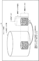
- FIG. 17 is a diagram conceptually illustrating an example in which a part of a physical disk group 52 (pool) is allocated as a logical disk 51 in a general storage device 50 (a storage device that does not use the thin provisioning technology described later). is there. As shown in FIG. 17, in the storage device 50, a physical disk capacity corresponding to a predetermined capacity of the logical disk is allocated as a logical disk regardless of the actual data amount.
- FIG. 18 is a time chart of storage access control processing performed by a general storage access control device (not shown) for the storage device 50. As shown in FIG. 18, the storage access control apparatus sequentially executes pool construction, logical disk creation, and format processing. A host device (not shown) that can access the storage device 50 may issue a write request for a logical address in a storage area that has not yet been formatted. In this case, the storage access control apparatus needs to perform format processing while processing the write request.
- FIG. 19 is a diagram conceptually illustrating an example in which a part of the physical disk group 62 is allocated as the logical disk 61 in the storage apparatus 60 using the thin provisioning technology.
- the physical disk capacity corresponding to the predetermined capacity of the logical disk including the storage area that is not actually used is allocated as the logical disk.
- the thin provisioning technology is a technology developed to solve such problems.
- the physical disk capacity corresponding to the actual data amount is allocated as a logical disk.
- FIG. 20 is a time chart of storage access control processing performed by a general storage access control device (not shown) for the storage device 60.
- the storage access control apparatus sequentially executes pool construction, logical disk creation, and format processing.
- a host device (not shown) that can access the storage device 60 may issue a write request for a logical address in a storage area that is not yet assigned as a logical disk.
- the storage access control apparatus needs to allocate a physical disk as a logical disk and perform a format process for the storage area while processing the write request.
- Patent Documents 1 to 3 do not mention this problem.
- the main object of the present invention is to provide a storage access control device or the like that solves this problem.
- the storage access control apparatus is provided for at least one of the plurality of physical storage areas in the storage apparatus before being allocated as a logical storage area accessible from a host apparatus that accesses the storage apparatus.
- the format execution means for performing the format process, whether each of the physical storage areas has been allocated as one of the plurality of logical storage areas, and whether the format process has been executed.
- Storage means for storing area management information indicating whether or not, and when the host device accesses the specific logical storage area to which none of the plurality of physical storage areas is allocated, the area management In the information, it has not been allocated as the logical storage area, and An allocation control means for allocating the first physical storage area in the standby state, which indicates that the formatting process has been executed, as the specific logical storage area, and the format execution means and the allocation control means, Updating means for updating the area management information stored in the storage means in accordance with processing to be performed on the storage area;
- a storage access control method provides a storage access control method prior to allocation by an information processing apparatus as a logical storage area accessible from a host apparatus that accesses the storage apparatus. Whether at least one of the plurality of physical storage areas in the device is formatted, whether the state of each of the physical storage areas has been allocated as any of the plurality of logical storage areas, In addition, area management information indicating whether or not the formatting process has been performed is stored in a storage unit, and the host apparatus transfers to the specific logical storage area to which none of the plurality of physical storage areas is allocated.
- the logical storage area when the access occurs, the logical storage area
- the first physical storage area that is not allocated and is in a standby state indicating that the formatting process has been executed is allocated as the specific logical storage area, and the physical storage area is assigned to the physical storage area.
- the area management information stored in the storage unit is updated according to the processing to be performed.
- a storage access control program provides a plurality of storage devices that can be accessed by a host device that accesses the storage device with respect to the state of each physical storage area in the storage device.
- a logical storage area a computer accessible to storage means for storing area management information indicating whether or not the logical storage area has been allocated and whether or not the formatting process has been executed.
- the first physical storage area that is not assigned as the logical storage area and indicates that the formatting process has been executed and is in a standby state is assigned as the specific logical storage area.
- the present invention can also be realized by a computer-readable non-volatile recording medium storing such a storage access control program (computer program).
- the present invention makes it possible to improve the response performance to write access to a storage device that requires formatting.
- FIG. 1 is a block diagram showing a configuration of a storage access control system 1 according to a first embodiment of the present invention. It is a figure which illustrates the structure of the area
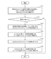
- 4 is a flowchart showing an operation when the storage access control apparatus 10 according to the first embodiment of the present invention performs VLDN format processing at a predetermined timing.
- 4 is a flowchart showing an operation when the storage access control apparatus 10 according to the first embodiment of the present invention receives a write request from the host apparatus 2 to the storage apparatus 20.
- 4 is a flowchart showing an operation when the storage access control apparatus 10 according to the first embodiment of the present invention receives a request for deleting or reducing the storage capacity of a logical disk from the host apparatus 2.
- FIG. 1 is a block diagram conceptually showing a storage access control system 1 according to the first embodiment of the present invention.
- the storage access control system 1 roughly includes a storage access control device 10 and a storage device 20.
- the storage access control system 1 is communicably connected to the host device 2.
- the storage access control device 10 is a device that processes data read requests and data write requests from the host device 2 to the storage device 20.
- the storage access control system 1 may be constructed as a storage device composed of a single housing.
- the storage device 20 stores data used by the host device 2.
- the storage device 20 includes a physical disk group 22 including one or more physical disks.
- m is an arbitrary integer greater than or equal to 2
- logical disks 21-1 to 21-m included in the logical disk group 21 the storage access control apparatus 10 allocates any storage area in the physical disk group 22. Created by.
- the address (logical address) specified when the host device 2 accesses the storage device 20 is an address in the logical disk group 21.
- the conversion from the logical address in the logical disk group 21 to the physical address in the physical disk group 22 is performed by the storage access control device 10 having an address conversion function.
- the storage access control device 10 includes a format execution unit 11, a storage unit 12, an allocation control unit 13, and an update unit 14.
- the format execution unit 11, the allocation control unit 13, and the update unit 14 may be electronic circuits, or may be realized by a computer program and a processor that operates according to the computer program.
- the storage unit 12 is a storage device such as a memory or a magnetic disk.
- the storage unit 12 has a storage control function realized by an electronic circuit or a computer program and a processor that operates according to the computer program.
- the storage access control apparatus 10 manages a storage area of a predetermined size in the physical disk group 22 as a management unit after constructing a pool of the physical disk group 22.
- this management unit is referred to as VLDN (Virtual Logical Disk Disk Number).
- the physical disk group 22 according to this embodiment includes n (n is an arbitrary integer greater than or equal to 2) VLDNs 22-1 to 22-n.
- the VLDNs 22-1 to 22-n are managed by the storage access control apparatus 10 before the logical disks 21-1 to 21-m are created.
- the VLDNs 22-1 to 22-n do not have to coincide with the divisions of the physical disks constituting the physical disk group 22.
- the storage access control apparatus 10 When the storage access control apparatus 10 according to the present embodiment creates a logical disk 21-i (i is any natural number from 1 to m), it creates an LDN (Logical Disk Number) for the created logical disk 21-i. ), The logical disk 21-i is managed.
- LDN Logical Disk Number
- the storage unit 12 stores area management information 120.
- the area management information 120 is information for managing each VLDN and associating the VLDN with the LDN.
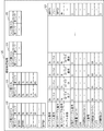
- FIG. 2 is a diagram illustrating a configuration example of the area management information 120.
- the area management information 120 includes a VLDN conversion table 121, a VLDN link table (free) 122, a VLDN link table (format) 123, a VLDN link table (standby) 124, and a VLDN link table (active) 125. Is included.
- the VLDN conversion table 121 is a table indicating the state of each VLDN.
- the “table number” in the VLDN conversion table 121 is an identifier that can identify the VLDN.
- “Table attribute” is information indicating the state of the VLDN.
- the storage access control apparatus 10 sets the VLDN to any one of four states of “free”, “format”, “standby”, and “active”. Details of these states will be described later.
- the storage access control apparatus 10 performs link management for each VLDN group set to the same state among these four states.
- Link management means that VLDNs belonging to the group are logically connected by linking the VLDNs belonging to the group in a circular manner (that is, the last VLDN is connected to the first VLDN). This is a management method.
- the storage access control apparatus 10 may manage the VLDN by a method other than link management.
- the “previous link table number” and “rear link table number” in the VLDN conversion table 121 are the table numbers of the VLDN located (linked) before and after the VLDN.
- “Table status” is information indicating the execution status of the format process for the VLDN.
- the “LDN capacity” is the storage capacity of the logical disk 21-i specified by the LDN associated with the VLDN.
- VLDN capacity is the storage capacity of the VLDN.
- the VLDN link table (free) 122 is a table indicating the number of VLDNs in the free state (number of links) and the table numbers of the VLDNs positioned before and after each VLDN in the free state.
- the VLDN link tables 123 to 125 are in order: It is a table which shows the same content as VLDN link table (free) 122 about VLDN in a formatting state, a standby state, and an active state.
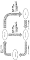
- FIG. 3 is an example of a state transition diagram regarding the VLDNs 22-1 to 22-n according to the present embodiment.
- the VLDNs 22-1 to 22-n are in a free state in the initial state.
- the storage access control device 10 starts a format process for at least one of the VLDNs 22-1 to 22-n after constructing a pool of the physical disk group 22.
- the VLDN in which the format process is being prepared for execution or being executed is transitioned from the free state to the format state.
- This standby state is a state indicating that the disk has not been assigned as a logical disk and the formatting process has been executed. That is, this standby state is a state representing that it can be allocated as a logical disk without requiring formatting processing.
- the storage access control device 10 allocates at least one of the VLDNs in the standby state as a logical disk as necessary.
- the VLDN assigned as the logical disk transitions from the standby state to the active state.
- This active state is a state representing that the logical disk has already been allocated.
- the storage access control device 10 deletes or reduces the storage capacity of the logical disk according to the instruction from the host device 2. At this time, the VLDN allocated as the logical disk with the deleted or reduced storage capacity transitions to the free state or the formatted state depending on whether or not the number of VLDNs in the standby state is equal to or larger than the threshold value.
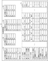
- FIGS. 4A and 4B (the VLDN conversion table 121 is divided and described for convenience of drawing notation) is a diagram illustrating a setting example of the area management information 120 according to the present embodiment.
- the total storage capacity of the physical disk group 22 is 3P (peta) bytes
- the individual storage capacities of the VLDNs 22-1 to 22-n are 64G (giga) bytes.
- the value of n is C000h (h represents a hexadecimal number).
- VLDN0 to 2 table attributes of three VLDNs (hereinafter referred to as “VLDN0 to 2”) having table numbers 0h to 2h are in an active state.
- VLDN0 to VLDN2 are linked in that order.
- the records in the third line from the top in each of the link tables 122 to 125 shown in FIGS. 4A and 4B indicate the VLDN located at the end and the first of the link. Since VLDN0 and VLDN2 are in the active state, the formatting process is completed as can be seen from the state transition diagram shown in FIG. VLDN0 to VLDN2 are allocated as logical disks having an LDN of “7” and a storage capacity of 196 Gbytes.
- VLDN3 to 8 table attributes of six VLDNs (hereinafter referred to as “VLDN3 to 8”) having table numbers 3h to 8h are in a standby state.
- VLDN link table (standby) 124 the VLDNs 3 to 8 are linked in that order. Since the VLDNs 3 to 8 are in the standby state, the formatting process is completed.
- “ ⁇ ” in the VLDN conversion table 121 is a symbol indicating that a value is not set. For example, a value that cannot be taken is set in a portion where “ ⁇ ” is written. Yes.
- VLDN9 to B the table attributes of three VLDNs (hereinafter referred to as “VLDN9 to B”) having table numbers 9h to Bh are in the format state.
- VLDN conversion table 121 and the VLDN link table (format) 123 the VLDNs 9 to B are linked in that order.
- the VLDNs 9 to B are in a status of “format complete”, “during formatting”, and “format request” in order regarding the execution status of the format process.
- VLDN is in a free state.
- VLDN conversion table 121 and the VLDN link table (free) 122 these other VLDNs are linked in that order.
- the format execution unit 11 shown in FIG. 1 formats the VLDNs 22-1 to 22-n before the VLDNs 22-1 to 22-n are allocated as the logical disks 21-i (i is at least one natural number from 1 to m).
- the format execution unit 11 refers to the area management information 120 stored in the storage unit 12 at a predetermined timing (for example, periodically) to check whether the number of VLDNs in the standby state satisfies the criterion A.
- the reference A is, for example, “is a predetermined threshold value X or more”.
- the format execution unit 11 When the number of VLDNs in the standby state does not satisfy the criterion A, the format execution unit 11 performs at least one of VLDNs 22-j (j is a natural number of at least one of 1 to m) in the free state in the area management information 120. Format processing is performed on either of them. After performing the format process, the format execution unit 11 performs the format process so that the number of VLDNs in the standby state can satisfy the criterion A. For example, when the number of VLDNs in the standby state is three less than the reference A, the format execution unit 11 performs the formatting process on at least three of the VLDNs 22-j in the free state. The format execution unit 11 notifies the update unit 14 of the execution status of the format process.
- the allocation control unit 13 shown in FIG. 1 controls the VLDNs 22-1 to 22-n to be allocated as the logical disk 21-i and to cancel the allocation.
- the allocation control unit 13 associates LDN and VLDN in this allocation process.
- the allocation control unit 13 confirms whether or not the write address in the write request to the storage apparatus 20 issued from the host apparatus 2 exists in the logical disk group 21.
- the allocation control unit 13 newly allocates the VLDN 22-j in the standby state as the logical disk 21-i including the write address in the area management information 120.
- the allocation control unit 13 notifies the update unit 14 of the execution status of this allocation process.
- the allocation control unit 13 When the allocation control unit 13 receives a request issued from the host device 2 to delete or reduce the storage capacity of the logical disk 21-i in the storage apparatus 20, the VLDN 22- allocated as the logical disk 21-i. For j, the assignment is released. Thereby, the allocation control unit 13 deletes the logical disk 21-i or reduces the storage capacity. The allocation control unit 13 notifies the host device 2 that the logical disk 21-i has been deleted or the storage capacity has been reduced.
- the update unit 14 illustrated in FIG. 1 updates the area management information 120 stored in the storage unit 12 in accordance with processing performed by the format execution unit 11 and the allocation control unit 13 on the VLDNs 22-1 to 22-n. .
- the update unit 14 updates the VLDN conversion table 121 according to the execution status of the format process when the format execution unit 11 performs the format process on at least one of the VLDNs 22-j in the free state.
- the updating unit 14 updates the table attribute related to the VLDN in the VLDN conversion table 121 from “free” to “format”, and then updates from “format” to “standby”.
- the updating unit 14 updates the table state relating to the VLDN in the VLDN conversion table 121 from “format request” to “formatting”, and then updates from “formatting” to “formatting complete”.
- the update unit 14 also updates the VLDN link tables 122 to 124 together with the update of the VLDN conversion table 121.
- the updating unit 14 executes the allocation process when the allocation control unit 13 allocates the VLDN 22-j in the standby state as the logical disk 21-i including the write address in the write request newly issued from the host device 2.
- the VLDN conversion table 121 is updated according to the situation.
- the updating unit 14 updates the table attribute related to the VLDN in the VLDN conversion table 121 from “standby” to “active”.
- the updating unit 14 updates the VLDN link tables 124 and 125 together with the update of the VLDN conversion table 121.
- the update unit 14 When the update unit 14 receives a request issued from the host device 2 to delete the logical disk 21-i in the storage device 20 or to reduce the storage capacity, the update unit 14 refers to the area management information 120 and refers to the VLDN in the standby state. Check whether the number meets the criterion B.
- the reference B is, for example, “is a predetermined threshold Y or more”.
- the reference B may be the same as or different from the reference A used in the formatting process by the format execution unit 11.
- the updating unit 14 changes the table attribute in the VLDN conversion table 121 from “active” to “free” for the VLDN 22-j allocated as the logical disk 21-i. Update to The updating unit 14 updates the VLDN link tables 122 and 125 together with the update of the VLDN conversion table 121.
- the updating unit 14 changes the table attribute in the VLDN conversion table 121 from “active” to “format” with respect to the VLDN 22-j allocated as the logical disk 21-i.
- Update to The update unit 14 also updates the VLDN link tables 123 and 125 together with the update of the VLDN conversion table 121.
- the update unit 14 updates the table attribute in the VLDN conversion table 121 from “format” to “standby” for the VLDN 22-j after the formatting process by the format execution unit 11 is completed for the VLDN 22-j.
- the update unit 14 also updates the VLDN link tables 123 and 124 together with the update of the VLDN conversion table 121.
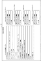
- FIG. 5 is a diagram illustrating an example of an initial state of the area management information 120. Also in the examples shown in FIGS. 5 to 10, as in the examples shown in FIGS. 4A and 4B, the total storage capacity of the physical disk group 22 is 3P bytes, and the individual storage capacity of the VLDNs 22-1 to 22-n is 64G. It is a byte. As shown in FIG. 5, in the initial state, all VLDNs are in a free state.
- FIG. 6 shows the format execution for four VLDNs (hereinafter referred to as “VLDN0 to 3”) whose table numbers are 0h to 3h when VLDNs 22-1 to 22-n are in the state shown in FIG.
- FIG. 6 is a diagram showing area management information 120 updated by an update unit 14 when format processing by the unit 11 is performed. As shown in FIG. 6, the contents relating to VLDN0 to VLDN3 are updated from the free state to the format state.
- FIG. 7 is a diagram showing the area management information 120 updated by the update unit 14 after the formatting process for VLDNs 0 to 2 is completed when the VLDNs 22-1 to 22-n are in the state shown in FIG. . As shown in FIG. 7, the contents relating to VLDN0 to VLDN2 are updated from the formatted state to the standby state.
- FIG. 8 shows the update unit 14 when the assignment control unit 13 assigns the VLDNs 02-1 and 22-n to the logical disk 21-i when the VLDNs 22-1 to 22-n are in the state shown in FIG. It is a figure which shows the area
- FIG. 9 shows that the update unit 14 updates the assignment of the VLDN0 to the logical disk 21-i by the assignment control unit 13 when the VLDNs 22-1 to 22-n are in the state shown in FIG. It is a figure which shows the performed area
- FIG. FIG. 9 is a diagram showing the area management information 120 updated when the number of VLDNs in the standby state satisfies the standard B. As shown in FIG. 9, the contents regarding VLDN0 are updated from the active state to the free state. Further, the storage capacity of the logical disk 21-i is updated from 128 Gbytes to 64 Gbytes.
- FIG. 10 shows that the update unit 14 updates the assignment of the VLDN 0 to the logical disk 21-i by the assignment control unit 13 when the VLDNs 22-1 to 22-n are in the state shown in FIG. It is a figure which shows the performed area
- FIG. FIG. 10 is a diagram showing the area management information 120 updated when the number of VLDNs in the standby state does not satisfy the standard B. As shown in FIG. 10, the contents relating to VLDN0 are updated from the active state to the formatted state.
- FIG. 11 is a flowchart showing an operation when the storage access control apparatus 10 according to the present embodiment performs VLDN format processing at a predetermined timing.
- the format execution unit 11 refers to the area management information 120 at a predetermined timing, and confirms whether or not the number of VLDNs in the standby state satisfies the criterion A (step S101). When the number of VLDNs in the standby state satisfies the criterion A (Yes in step S102), the entire process ends. When the number of VLDNs in the standby state does not satisfy the standard A (No in Step S102), the format execution unit 11 refers to the area management information 120 and starts the formatting process for the VLDN 22-j in the free state (Step S102). S103).
- the update unit 14 updates the area management information 120 from the free state to the format state for the VLDN 22-j (step S104).
- the format execution unit 11 completes the format process for the VLDN 22-j (step S105).
- the updating unit 14 updates the area management information 120 from the formatted state to the standby state with respect to the VLDN 22-j (step S106), and the entire process ends.
- FIG. 12 is a flowchart showing an operation when the storage access control apparatus 10 according to the present embodiment receives a write request from the host apparatus 2 to the storage apparatus 20.
- the storage access control device 10 receives a write request to the storage device 20 from the host device 2 (step S201).
- the allocation control unit 13 checks whether the write address in the write request to the storage device 20 exists in the logical disk group 21 (step S202). If the write address exists in the logical disk group 21 (Yes in step S203), the process proceeds to step S206.
- the allocation control unit 13 refers to the area management information 120 and newly includes the VLDN 22-j in the standby state including the write address.
- the logical disk 21-i is allocated (step S204).
- the updating unit 14 updates the area management information 120 from the standby state to the active state with respect to the VLDN 22-j (Step S205).
- the storage access control device 10 executes a write process to the write address (step S206), and the entire process ends.
- FIG. 13 is a flowchart showing an operation when the storage access control apparatus 10 according to the present embodiment receives a request for deleting or reducing the storage capacity of a logical disk from the host apparatus 2.
- the storage access control device 10 receives a request to delete or reduce the storage capacity of the logical disk 21-i in the storage device 20 from the host device 2 (step S301).
- the updating unit 14 refers to the area management information 120 and checks whether or not the number of VLDNs in the standby state satisfies the criterion B (step S302). When the number of VLDNs in the standby state satisfies the criterion B (Yes in step S303), the update unit 14 changes the area management information 120 from the active state to the free state for the VLDN 22-j allocated as the logical disk 21-i. (Step S304).
- the update unit 14 formats the area management information 120 from the active state for the VLDN 22-j allocated as the logical disk 21-i.
- the state is updated (step S305).
- the format execution unit 11 performs format processing on the VLDN 22-j (step S306).
- the update unit 14 updates the area management information 120 from the formatted state to the standby state with respect to the VLDN 22-j (Step S307).
- the allocation control unit 13 deletes or reduces the storage capacity of the logical disk 21-i, notifies the host device 2 that the process has been performed (step S308), and the entire process ends.
- the storage access control device 10 can improve the response performance to write access to a storage device that requires format processing.
- the reason is that the format execution unit 11 performs a format process on the physical storage area (VLDN) in the storage apparatus 20 at a predetermined timing before being allocated as a logical storage area (logical disk), and the allocation control unit 13 This is because a physical storage area that has been formatted and is not assigned as a logical storage area is assigned as a logical storage area.
- Protected information is generally added to data stored in the storage device so as to improve reliability.
- protection information for example, a sector number of a logical disk is used. Therefore, the formatting process for the storage area of the physical disk is normally performed after the logical disk is created.
- a host device that accesses the storage device may issue a write request for a logical address in a storage area that has not been formatted. In this case, since the storage access control apparatus needs to perform the formatting process while processing the write request, there is a problem that the response performance with respect to the write access to the storage apparatus is deteriorated.
- the format execution unit 11 is a logical disk that can be accessed by the host apparatus 2 with respect to at least one of the plurality of VLDNs in the storage apparatus 20. Format before assigning.
- the storage unit 12 stores area management information 120 indicating whether or not each VLDN state has been assigned as a logical disk and whether or not the formatting process has been executed.
- the assignment control unit 13 has not been assigned as a logical storage area in the area management information 120, and the formatting process has been executed (that is, A VLDN (in a standby state) is allocated as a logical disk to be accessed.
- the update unit 14 updates the area management information 120 stored in the storage unit 12 in accordance with processing performed by the format execution unit 11 and the allocation control unit 13 on the VLDN.
- the storage access control apparatus 10 according to the present embodiment can improve the response performance to the write access to the storage apparatus that requires the format process.
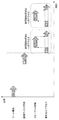
- FIG. 21 is an example of a time chart of storage access control processing performed by the storage access control apparatus 10 according to the present embodiment. As shown in FIG. 21, the storage access control apparatus 10 according to the present embodiment does not need to perform format processing while processing a write request, unlike the general storage access control apparatus shown in FIG. 18 or FIG. The response performance to write access to the storage apparatus can be improved.
- the format execution unit 11 refers to the area management information 120 at a predetermined timing (for example, periodically), and the VLDN in the standby state indicated by the area management information 120 If the number does not satisfy the standard, format processing is performed on at least one of the VLDNs 22-1 to 22-n.
- the storage access control apparatus 10 according to the present embodiment can quickly allocate a VLDN as a logical disk by securing at least a reference number of VLDNs in a standby state.
- the updating unit 14 when the allocation as a logical disk is canceled for any VLDN, uses the number of VLDNs in the standby state indicated by the area management information 120 as a reference. If the above condition is not satisfied, the state of the VLDN whose allocation as the logical disk is released is updated from the active state to the formatted state. When the number of VLDNs in the standby state satisfies the criterion, the updating unit 14 updates the state of the VLDNs whose allocation as a logical disk has been released from the active state to the free state. Therefore, the storage access control apparatus 10 according to the present embodiment can quickly allocate a VLDN as a logical disk by securing at least a reference number of VLDNs in a standby state.
- the storage unit 12 stores the area management information 120 according to the capacity that can be stored in the device mounted on the storage apparatus 20 or the usage status of the storage apparatus 20.
- the VLDN to be managed may be added or deleted as needed.
- the storage access control device 10 according to the present embodiment can flexibly cope with the case where the storage capacity of the storage device 20 is changed.
- FIG. 14 is a block diagram conceptually showing the configuration of the storage access control apparatus 30 according to the second embodiment.
- the storage access control device 30 includes a format execution unit 31, a storage unit 32, an allocation control unit 33, and an update unit 34.
- the format execution unit 31 has a plurality of physical storage areas 42-1 to 42-n (n is 2 or more) in the storage apparatus 40 before being assigned as a logical storage area accessible from the host apparatus 3 that accesses the storage apparatus 40. Format processing is performed on at least one of the arbitrary integers).
- the storage unit 32 has already been assigned as one of a plurality of logical storage areas 41-1 to 41-m (m is an arbitrary integer greater than or equal to 2) for each state of the physical storage areas 42-1 to 42-n. It stores area management information 320 indicating whether or not the format processing has been executed.
- the allocation control unit 33 is a specific logical storage area 41-i to which any of the plurality of physical storage areas 42-1 to 42-n is not allocated by the host device 3 (i is any natural number from 1 to m).
- the first physical storage area 42-j (j is a natural number of at least one of 1 to n) is assigned as a specific logical storage area 41-i.
- the first physical storage area 42-j is a physical storage area in a standby state that is not allocated as a logical storage area in the area management information 320 and indicates that the formatting process has been executed.
- the update unit 34 updates the area management information 320 stored in the storage unit 32 in accordance with the processing performed by the format execution unit 31 and the allocation control unit 33 for the physical storage areas 42-1 to 42-n.
- the storage access control device 30 can improve the response performance with respect to write access to a storage device that requires format processing.
- the reason is that the format execution unit 31 performs a format process on the physical storage area in the storage device 40 before being allocated as a logical storage area, and the allocation control unit 33 has executed the format process, and This is because a physical storage area that is not assigned as a logical storage area is assigned as a logical storage area.
- each unit illustrated in FIGS. 1 and 14 can be realized by a dedicated HW (HardWare) (electronic circuit).
- HW HardWare
- 1 and 14 at least the following configuration can be regarded as a function (processing) unit (software module) of the software program.
- -Format execution units 11 and 31, A storage control function in the storage units 12 and 32; Allocation control units 13 and 33, Update units 14 and 34.
- FIG. 15 is a diagram illustrating an exemplary configuration of an information processing apparatus 900 (computer) that can execute the storage access control apparatus according to each embodiment of the present invention. That is, FIG. 15 is a configuration of a computer (information processing apparatus) capable of realizing the storage access control apparatus shown in FIGS. 1 and 14 and represents a hardware environment capable of realizing each function in the above-described embodiment. .
- the information processing apparatus 900 illustrated in FIG. 15 includes the following as constituent elements.
- CPU Central_Processing_Unit
- ROM Read_Only_Memory
- RAM Random_Access_Memory
- -Hard disk storage device
- a communication interface 905 with an external device ⁇ Bus 906 (communication line)
- the information processing apparatus 900 including the above-described components is a general computer in which these configurations are connected via a bus 906.
- the information processing apparatus 900 may include a plurality of CPUs 901 or may include a CPU 901 configured by a multi-core.
- the present invention described by taking the above embodiment as an example supplies a computer program capable of realizing the following functions to the information processing apparatus 900 shown in FIG.
- the function is the above-described configuration in the block configuration diagram (FIGS. 1 and 14) referred to in the description of the embodiment, or the function of the flowcharts (FIGS. 11 to 13).
- the present invention is then achieved by reading the computer program to the CPU 901 of the hardware, interpreting it and executing it.
- the computer program supplied to the apparatus may be stored in a readable / writable volatile memory (RAM 903) or a nonvolatile storage device such as the hard disk 904.
- a general procedure can be adopted as a method for supplying a computer program into the hardware.
- the procedure includes, for example, a method of installing in the apparatus via various recording media 907 such as a CD-ROM, and a method of downloading from the outside via a communication line such as the Internet.
- the present invention is configured by a code constituting the computer program or a recording medium 907 in which the code is stored.
Landscapes
- Engineering & Computer Science (AREA)
- Theoretical Computer Science (AREA)
- Physics & Mathematics (AREA)
- General Engineering & Computer Science (AREA)
- General Physics & Mathematics (AREA)
- Human Computer Interaction (AREA)
- Information Retrieval, Db Structures And Fs Structures Therefor (AREA)
- Signal Processing For Digital Recording And Reproducing (AREA)
Abstract
ストレージ装置への書き込みアクセスに対する応答性能を向上する。 ストレージアクセス制御装置30は、論理記憶領域として割り当てられる以前に、ストレージ装置40における物理記憶領域の少なくとも何れかに対して、フォーマット処理を行うフォーマット実行部31と、個々の物理記憶領域の状態について、論理記憶領域として割り当て済みであるか否か、及び、フォーマット処理が実行済みであるか否かを示す領域管理情報320を記憶する記憶部32と、物理記憶領域の何れも割り当てられていない論理記憶領域へのアクセスが発生したときに、論理記憶領域として割り当て済みでなく、かつ、フォーマット処理が実行済みの状態にある物理記憶領域を、その論理記憶領域として割り当てる割り当て制御部33と、フォーマット実行部31及び割り当て制御部33が行う処理に応じて、領域管理情報320を更新する更新部34と、を備える。
Description
本願発明は、フォーマット処理が必要なストレージ装置へのアクセスを制御する技術に関する。
高度に情報化された現代社会においては、大量のデータを記憶するRAID(Redundant Arrays of Inexpensive Disks)等のストレージ装置が、様々な場面において使用されている。このようなストレージ装置においては、記憶されたデータへのアクセス性能を向上させる技術が期待されている。
このような技術の一例として、特許文献1には、複数の記憶制御装置間の性能及び機能の違い、あるいは、複数の記憶制御装置間の距離等を考慮した記憶システムが開示されている。このシステムでは、第一及び第二の記憶制御装置が備えるコントローラ同士が、当該コントローラの内部バスと同種類の接続媒体よりも最大通信距離が長い接続媒体を介して接続されている。このシステムでは、第一の記憶制御装置が、自装置に接続されている1以上のホスト装置に、第二の記憶制御装置が有する論理ボリュームを仮想化して提供する。このシステムでは、第二の記憶制御装置が、自装置に接続されている1以上のホスト装置に、第一の記憶制御装置が有する論理ボリュームを仮想化して提供する。
また、特許文献2には、複数のページを備えるチャンク単位で、仮想ボリュームに実記憶領域を割り当てる記憶制御装置が開示されている、この記憶制御装置は、RAIDグループ間で負荷の偏りが生じた場合に、データの再配置を行う。
また、特許文献3には、光磁気ディスク等の高密度データ記憶媒体を、一度に全部ではなく、分配時間基準によりフォーマットするシステムが開示されている。このシステムは、当該データ記憶媒体への書込み要求時に、データを消去する必要を排除することにより、当該データ記憶媒体にデータを格納するのに必要な時間を減少する。
RAID等のストレージ装置では、複数の物理ディスクを束ねた仮想媒体(以降、「プール」と称する)を構成し、プールの領域を分割した論理ディスクを構築する。このようなストレージ装置は、プールを構成する物理ディスク群における何れかの記憶領域を、論理ディスクとして割り当てたのち、物理ディスク群における当該記憶領域に対してフォーマット処理を行う。このようなストレージ装置へアクセスするサーバ装置等のホスト装置は、このフォーマット処理が完了したのち、当該論理ディスクへ書き込みアクセスすることが可能となる。
ストレージ装置に格納されるデータは、信頼性が向上するように、一般的に保護情報が付加されている。このような保護情報として、標準化団体T10により規定されたT10-DIF(Data Integrity Field)等が知られている。図16は、T10-DIFを使用したデータの構成例を示す図である。図16に示す通り、T10-DIFでは、512バイトごとに8バイトのDIF(保護情報)を付加する。DIFは、16ビットのGRD(guard tag)フィールドと、16ビットのAPP(application tag)フィールドと、32ビットのREF(reference tag)フィールドと、により構成される。このREFフィールドとして、一般的に論理ディスクのセクタ番号であるLSN(Logical Sector Number)が使用される。したがって、上述したフォーマット処理は、通常、論理ディスクが作成された後に行われる。
図17は、一般的なストレージ装置50(後述するシン・プロビジョニング技術を使用しないストレージ装置)において、物理ディスク群52(プール)の一部を論理ディスク51として割り当てる例を概念的に説明する図である。図17に示す通り、ストレージ装置50では、実際のデータ量に関係なく、論理ディスクの所定容量分の物理ディスクの容量が、論理ディスクとして割り当てられる。
図18は、ストレージ装置50に対して、一般的なストレージアクセス制御装置(不図示)が行うストレージアクセス制御処理のタイムチャートである。図18に示す通り、ストレージアクセス制御装置は、プールの構築、論理ディスクの作成、及び、フォーマット処理を順次実行する。ストレージ装置50にアクセス可能なホスト装置(不図示)は、フォーマット処理がまだ行われていない記憶領域内の論理アドレスに対する書き込み要求を発行する場合がある。この場合、ストレージアクセス制御装置は、当該書き込み要求を処理中に、フォーマット処理を行う必要がある。
図19は、シン・プロビジョニング技術を使用したストレージ装置60において、物理ディスク群62の一部を論理ディスク61として割り当てる例を概念的に説明する図である。図17に示すストレージ装置50では、実際に使用されていない記憶領域も含めて、論理ディスクの所定容量分の物理ディスクの容量が、論理ディスクとして割り当てられるので、物理ディスクに生じる無駄が大きいという問題がある。シン・プロビジョニング技術は、このような問題を解決するために開発された技術である。図19に示す通り、ストレージ装置60では、実際のデータ量分の物理ディスクの容量が、論理ディスクとして割り当てられる。
図20は、ストレージ装置60に対して、一般的なストレージアクセス制御装置(不図示)が行うストレージアクセス制御処理のタイムチャートである。図20に示す通り、ストレージアクセス制御装置は、プールの構築、論理ディスクの作成、及び、フォーマット処理を順次実行する。ストレージ装置60にアクセス可能なホスト装置(不図示)は、論理ディスクとしてまだ割り当てられていない記憶領域内の論理アドレスに対する書き込み要求を発行する場合がある。この場合、ストレージアクセス制御装置は、当該書き込み要求を処理中に、当該記憶領域について、物理ディスクを論理ディスクとして割り当てるとともに、フォーマット処理を行う必要がある。
上述したとおり、図17乃至図20に示すストレージ装置に対する記憶アクセス制御処理では、フォーマット処理が行われていない記憶領域内の論理アドレスに対する書き込み要求が発生した場合に、当該書き込み要求を処理中にフォーマット処理を行う必要がある。この場合、ストレージ装置への書き込みアクセスに対する応答性能が低下するという問題がある。特許文献1乃至3は、この問題について言及していない。本願発明の主たる目的は、この問題を解決したストレージアクセス制御装置等を提供することである。
本願発明の一態様に係るストレージアクセス制御装置は、ストレージ装置へアクセスするホスト装置からアクセス可能な論理記憶領域として割り当てられる以前に、前記ストレージ装置における複数の物理記憶領域のうちの少なくとも何れかに対して、フォーマット処理を行うフォーマット実行手段と、個々の前記物理記憶領域の状態について、複数の前記論理記憶領域のいずれかとして割り当て済みであるか否か、及び、前記フォーマット処理が実行済みであるか否かを示す領域管理情報を記憶する記憶手段と、前記ホスト装置による、前記複数の物理記憶領域の何れも割り当てられていない特定の前記論理記憶領域へのアクセスが発生したときに、前記領域管理情報において、前記論理記憶領域として割り当て済みでなく、かつ、前記フォーマット処理が実行済みであることを表す、スタンバイ状態にある第一の前記物理記憶領域を、前記特定の論理記憶領域として割り当てる割り当て制御手段と、前記フォーマット実行手段及び前記割り当て制御手段が、前記物理記憶領域に対して行う処理に応じて、前記記憶手段に記憶された前記領域管理情報を更新する更新手段、を備える。
上記目的を達成する他の見地において、本願発明の一態様に係るストレージアクセス制御方法は、情報処理装置によって、ストレージ装置へアクセスするホスト装置からアクセス可能な論理記憶領域として割り当てられる以前に、前記ストレージ装置における複数の物理記憶領域のうちの少なくとも何れかに対して、フォーマット処理を行い、個々の前記物理記憶領域の状態について、複数の前記論理記憶領域のいずれかとして割り当て済みであるか否か、及び、前記フォーマット処理が実行済みであるか否かを示す領域管理情報を記憶手段に記憶し、 前記ホスト装置による、前記複数の物理記憶領域の何れも割り当てられていない特定の前記論理記憶領域へのアクセスが発生したときに、前記領域管理情報において、前記論理記憶領域として割り当て済みでなく、かつ、前記フォーマット処理が実行済みであることを表す、スタンバイ状態にある第一の前記物理記憶領域を、前記特定の論理記憶領域として割り当て、前記物理記憶領域に対して行う処理に応じて、前記記憶手段に記憶された前記領域管理情報を更新する。
また、上記目的を達成する更なる見地において、本願発明の一態様に係るストレージアクセス制御プログラムは、ストレージ装置における各々の物理記憶領域の状態について、前記ストレージ装置へアクセスするホスト装置がアクセス可能な複数の論理記憶領域のいずれかとして割り当て済みであるか否か、及び、フォーマット処理が実行済みであるか否かを示す領域管理情報を記憶する記憶手段にアクセス可能なコンピュータに、前記論理記憶領域として割り当てられる以前に、複数の前記物理記憶領域のうちの少なくとも何れかに対して、前記フォーマット処理を行うフォーマット実行処理と、前記ホスト装置による、前記複数の物理記憶領域の何れも割り当てられていない特定の前記論理記憶領域へのアクセスが発生したときに、前記領域管理情報において、前記論理記憶領域として割り当て済みでなく、かつ、前記フォーマット処理が実行済みであることを表す、スタンバイ状態にある第一の前記物理記憶領域を、前記特定の論理記憶領域として割り当てる割り当て制御処理と、前記フォーマット実行処理及び前記割り当て制御処理が、前記物理記憶領域に対して行う処理に応じて、前記記憶手段に記憶された前記領域管理情報を更新する更新処理と、を実行させるためのプログラムである。
更に、本願発明は、係るストレージアクセス制御プログラム(コンピュータプログラム)が格納された、コンピュータ読み取り可能な、不揮発性の記録媒体によっても実現可能である。
本願発明は、フォーマット処理が必要なストレージ装置への書き込みアクセスに対する応答性能を向上することを可能とする。
以下、本願発明の実施の形態について図面を参照して詳細に説明する。
<第1の実施形態>
図1は、本願発明の第1の実施の形態に係るストレージアクセス制御システム1を概念的に示すブロック図である。ストレージアクセス制御システム1は、大別して、ストレージアクセス制御装置10、及び、ストレージ装置20を備える。ストレージアクセス制御システム1は、ホスト装置2と通信可能に接続されている。ストレージアクセス制御システム1と通信可能に接続されるホスト装置は、複数であってもよい。ストレージアクセス制御装置10は、ホスト装置2からストレージ装置20に対する、データの読み出し要求及びデータの書き込み要求について処理する装置である。ストレージアクセス制御システム1は、1つの筐体からなるストレージ装置として構築されてもよい。
図1は、本願発明の第1の実施の形態に係るストレージアクセス制御システム1を概念的に示すブロック図である。ストレージアクセス制御システム1は、大別して、ストレージアクセス制御装置10、及び、ストレージ装置20を備える。ストレージアクセス制御システム1は、ホスト装置2と通信可能に接続されている。ストレージアクセス制御システム1と通信可能に接続されるホスト装置は、複数であってもよい。ストレージアクセス制御装置10は、ホスト装置2からストレージ装置20に対する、データの読み出し要求及びデータの書き込み要求について処理する装置である。ストレージアクセス制御システム1は、1つの筐体からなるストレージ装置として構築されてもよい。
ストレージ装置20は、ホスト装置2が使用するデータを記憶する。ストレージ装置20は、1以上の物理ディスクを含む物理ディスク群22を備えている。論理ディスク群21に含まれるm個(mは2以上の任意の整数)の論理ディスク21-1乃至21-mは、ストレージアクセス制御装置10が、物理ディスク群22におけるいずれかの記憶領域を割り当てることによって作成される。ホスト装置2がストレージ装置20にアクセスする際に指定するアドレス(論理アドレス)は、論理ディスク群21におけるアドレスである。論理ディスク群21における論理アドレスから、物理ディスク群22における物理アドレスへの変換は、アドレス変換機能を備えたストレージアクセス制御装置10によって行われる。
本実施形態に係るストレージアクセス制御装置10は、フォーマット実行部11、記憶部12、割り当て制御部13、及び、更新部14を備えている。フォーマット実行部11、割り当て制御部13、及び、更新部14は、電子回路の場合もあれば、コンピュータプログラムとそのコンピュータプログラムに従って動作するプロセッサによって実現される場合もある。記憶部12は、メモリあるいは磁気ディスク等の記憶デバイスである。記憶部12は、電子回路、あるいは、コンピュータプログラムとそのコンピュータプログラムに従って動作するプロセッサによって実現される記憶制御機能を備えている。
本実施形態に係るストレージアクセス制御装置10は、物理ディスク群22によるプールを構築したのち、物理ディクス群22における、所定の大きさの記憶領域を管理単位として管理する。本実施形態では、この管理単位をVLDN(Virtual Logical Disk Number)と称する。本実施形態に係る物理ディスク群22は、n個(nは2以上の任意の整数)のVLDN22-1乃至22-nを含んでいる。VLDN22-1乃至22-nは、論理ディスク21-1乃至21-mが作成される以前から、ストレージアクセス制御装置10によって管理される。VLDN22-1乃至22-nは、物理ディスク群22を構成する物理ディスクの区分と一致しなくてもよい。
本実施形態に係るストレージアクセス制御装置10は、論理ディスク21-i(iは1乃至mのいずれかの自然数)を作成したときに、生成した論理ディスク21-iに対してLDN(Logical Disk Number)を付与することにより、論理ディスク21-iを管理する。
記憶部12は、領域管理情報120を記憶している。領域管理情報120は、個々のVLDNを管理し、VLDNをLDNと関連付ける情報である。図2は、領域管理情報120の構成例を示す図である。図2に示す通り、領域管理情報120は、VLDN変換テーブル121、VLDNリンクテーブル(フリー)122、VLDNリンクテーブル(フォーマット)123、VLDNリンクテーブル(スタンバイ)124、及び、VLDNリンクテーブル(アクティブ)125を含んでいる。
VLDN変換テーブル121は、個々のVLDNの状態を示すテーブルである。VLDN変換テーブル121における「テーブル番号」はVLDNを識別可能な識別子である。「テーブル属性」は、VLDNの状態を表す情報である。本実施形態に係るストレージアクセス制御装置10は、VLDNを、「フリー」、「フォーマット」、「スタンバイ」、「アクティブ」という4つの状態のいずれかに設定する。これらの状態の詳細については後述する。
本実施形態に係るストレージアクセス制御装置10は、これら4つの状態のうち同じ状態に設定されたVLDNのグループごとにリンク管理を行う。リンク管理とは、当該グループに所属するVLDNを、環状に順番にひも付けする(すなわち、最後のVLDNが最初のVLDNに接続される)ことにより、当該グループに所属するVLDNが論理的に接続された態様になって管理する方法である。尚、ストレージアクセス制御装置10は、リンク管理以外の方法によりVLDNを管理してもよい。VLDN変換テーブル121における「前リンクテーブル番号」及び「後リンクテーブル番号」は、そのVLDNの前及び後に位置する(リンクされている)VLDNのテーブル番号である。「テーブル状態」は、VLDNに対するフォーマット処理の実行状況を表す情報である。「LDN容量」は、VLDNと関連付けされたLDNにより特定される論理ディスク21-iの記憶容量である。「VLDN容量」は、VLDNの記憶容量である。
VLDNリンクテーブル(フリー)122は、フリー状態にあるVLDNの個数(リンク数)、及び、フリー状態にある個々のVLDNについて、前後に位置するVLDNのテーブル番号を示すテーブルである。VLDNリンクテーブル123乃至125は、順に、
フォーマット状態、スタンバイ状態、及び、アクティブ状態にあるVLDNについて、VLDNリンクテーブル(フリー)122と同様の内容を示すテーブルである。
フォーマット状態、スタンバイ状態、及び、アクティブ状態にあるVLDNについて、VLDNリンクテーブル(フリー)122と同様の内容を示すテーブルである。
ここで、VLDNに関する上述した4つの状態について説明する。図3は、本実施形態に係るVLDN22-1乃至22-nに関する状態遷移図の例である。VLDN22-1乃至22-nは、初期状態では、フリー状態にある。ストレージアクセス制御装置10は、物理ディスク群22によるプールを構築したのち、VLDN22-1乃至22-nの少なくともいずれかに対して、フォーマット処理を開始する。フォーマット処理が実行準備中あるいは実行中であるVLDNは、フリー状態からフォーマットの状態に遷移する。
フォーマット状態にあるVLDNは、フォーマット処理が完了したのち、スタンバイ状態に遷移する。このスタンバイ状態は、論理ディスクとして割り当て済みでなく、かつ、フォーマット処理が実行済みであることを表す状態である。すなわち、このスタンバイ状態は、フォーマット処理を必要とせずに論理ディスクとして割り当て可能であることを表す状態である。
ストレージアクセス制御装置10は、必要に応じて、スタンバイ状態にあるVLDNのうちの少なくともいずれかを論理ディスクとして割り当てる。論理ディスクとして割り当てられたVLDNは、スタンバイ状態からアクティブ状態に遷移する。このアクティブ状態は、論理ディスクとして割り当て済みであることを表す状態である。
ストレージアクセス制御装置10は、ホスト装置2による指示にしたがって、論理ディスクについて、削除あるいは記憶容量を削減する。このとき、削除あるいは記憶容量が削減された論理ディスクとして割り当てられていたVLDNは、スタンバイ状態にあるVLDNの数が閾値以上であるか否かにより、フリー状態またはフォーマット状態に遷移する。
図4A及び4B(図面の表記上の都合により、VLDN変換テーブル121を分割して記載)は、本実施形態に係る領域管理情報120の設定例を示す図である。図4A及び4Bに示す例では、物理ディスク群22の総記憶容量は3P(ペタ)バイトであり、VLDN22-1乃至22-nの個々の記憶容量は64G(ギガ)バイトである。この場合、nの値はC000h(hは16進数であることを表す)となる。
図4A及び4Bに示す例におけるVLDN変換テーブル121では、テーブル番号が0h乃至2hである3つのVLDN(以降、「VLDN0乃至2」と称する)のテーブル属性は、アクティブ状態にある。VLDN変換テーブル121及びVLDNリンクテーブル(アクティブ)125が示す通り、VLDN0乃至2は、その順番にリンクしている。尚、図4A及び4Bに示す各リンクテーブル122乃至125における上から3行目のレコードは、リンクの最後と最初に位置するVLDNを示している。VLDN0乃至2は、アクティブ状態にあるので、図3に示す状態遷移図から判るように、フォーマット処理は完了している。VLDN0乃至2は、LDNが「7」であり記憶容量が196Gバイトである論理ディスクとして、割り当てられている。
図4A及び4Bに示す例におけるVLDN変換テーブル121では、テーブル番号が3h乃至8hである6つのVLDN(以降、「VLDN3乃至8」と称する)のテーブル属性は、スタンバイ状態にある。VLDN変換テーブル121及びVLDNリンクテーブル(スタンバイ)124が示す通り、VLDN3乃至8は、その順番にリンクしている。VLDN3乃至8は、スタンバイ状態にあるので、フォーマット処理は完了している。尚、VLDN変換テーブル121における「-」は、値が設定されていないことを示す記号であり、「-」が記載された部分には、例えば、その部分が取りえない値などが設定されている。
図4A及び4Bに示す例におけるVLDN変換テーブル121では、テーブル番号が9h乃至Bhである3つのVLDN(以降、「VLDN9乃至B」と称する)のテーブル属性は、フォーマット状態にある。VLDN変換テーブル121及びVLDNリンクテーブル(フォーマット)123が示す通り、VLDN9乃至Bは、その順番にリンクしている。VLDN9乃至Bは、フォーマット処理の実行状況に関しては、順に、「フォーマット完了」、「フォーマット中」、「フォーマット要求」の状況にある。
図4A及び4Bに示す例では、上述した12個のVLDN(即ち、テーブル番号が0h乃至BhであるVLDN)を除く、テーブル番号がCh(図面表記の都合により不図示)乃至BFFFhであるその他のVLDNは、フリー状態にあることとする。VLDN変換テーブル121及びVLDNリンクテーブル(フリー)122が示す通り、これらその他のVLDNは、その順番にリンクしている。これらその他のVLDNに関するフォーマット処理は、行われていない。
図1に示すフォーマット実行部11は、VLDN22-1乃至22-nが論理ディスク21-i(iは1乃至mの少なくともいずれかの自然数)として割り当てられる以前に、それらVLDNをフォーマット処理する。フォーマット実行部11は、所定のタイミング(例えば定期的)に、記憶部12に格納された領域管理情報120を参照し、スタンバイ状態にあるVLDNの数が基準Aを満たすか否かを確認する。この基準Aは、例えば、「所定の閾値X以上である」ことである。
フォーマット実行部11は、スタンバイ状態にあるVLDNの数が基準Aを満たさない場合、領域管理情報120においてフリー状態にあるVLDN22-j(jは1乃至mの少なくともいずれかの自然数)のうちの少なくともいずれかに対してフォーマット処理を行う。フォーマット実行部11は、フォーマット処理を行った後、スタンバイ状態にあるVLDNの数が基準Aを満たすことができるようにフォーマット処理を行う。フォーマット実行部11は、例えば、スタンバイ状態にあるVLDNの数が基準Aよりも3個少ない場合、フリー状態にあるVLDN22-jのうちの少なくとも3個に対してフォーマット処理を行う。フォーマット実行部11は、フォーマット処理の実行状況を、更新部14へ通知する。
図1に示す割り当て制御部13は、VLDN22-1乃至22-nに対して、論理ディスク21-iとして割り当てること、及び、その割り当てを解除するように制御する。割り当て制御部13は、この割り当て処理において、LDNとVLDNとを関連づける。割り当て制御部13は、ホスト装置2から発行されたストレージ装置20への書き込み要求における書き込みアドレスが、論理ディスク群21に存在するか否か確認する。割り当て制御部13は、当該書き込みアドレスが論理ディスク群21に存在しない場合、領域管理情報120において、スタンバイ状態にあるVLDN22-jを、新たに当該書き込みアドレスを含む論理ディスク21-iとして割り当てる。割り当て制御部13は、この割り当て処理の実行状況を、更新部14へ通知する。
割り当て制御部13は、ホスト装置2から発行された、ストレージ装置20における論理ディスク21-iについて、削除あるいは記憶容量を削減する要求を受け付けた場合、論理ディスク21-iとして割り当てられているVLDN22-jに関して、その割り当てを解除する。これにより、割り当て制御部13は、論理ディスク21-iを削除あるいは記憶容量を削減する。割り当て制御部13は、論理ディスク21-iについて、削除あるいは記憶容量を削減したことを、ホスト装置2へ通知する。
図1に示す更新部14は、フォーマット実行部11及び割り当て制御部13が、VLDN22-1乃至22-nに対して行う処理に応じて、記憶部12に記憶された領域管理情報120を更新する。更新部14は、フォーマット実行部11がフリー状態にあるVLDN22-jのうちの少なくともいずれかに対してフォーマット処理を行う際に、フォーマット処理の実行状況に応じて、VLDN変換テーブル121を更新する。更新部14は、VLDN変換テーブル121における、当該VLDNに関するテーブル属性を、「フリー」から「フォーマット」に更新したのち、さらに「フォーマット」から「スタンバイ」に更新する。更新部14は、VLDN変換テーブル121における、当該VLDNに関するテーブル状態を、「フォーマット要求」から「フォーマット中」に更新したのち、さらに「フォーマット中」から「フォーマット完了」に更新する。更新部14は、VLDN変換テーブル121の更新とあわせて、VLDNリンクテーブル122乃至124も更新する。
更新部14は、割り当て制御部13が、スタンバイ状態にあるVLDN22-jを、新たにホスト装置2から発行された書き込み要求における書き込みアドレスを含む論理ディスク21-iとして割り当てる際に、割り当て処理の実行状況に応じて、VLDN変換テーブル121を更新する。更新部14は、VLDN変換テーブル121における、当該VLDNに関するテーブル属性を、「スタンバイ」から「アクティブ」に更新する。更新部14は、VLDN変換テーブル121の更新とあわせて、VLDNリンクテーブル124及び125も更新する。
更新部14は、ホスト装置2から発行された、ストレージ装置20における論理ディスク21-iを削除あるいは記憶容量を削減する要求を受け付けた場合、領域管理情報120を参照し、スタンバイ状態にあるVLDNの数が基準Bを満たすか否かを確認する。この基準Bは、例えば、「所定の閾値Y以上である」ことである。尚、この基準Bは、フォーマット実行部11によるフォーマット処理において使用される基準Aと同じでもよいし、異なってもよい。
更新部14は、スタンバイ状態にあるVLDNの数が基準Bを満たす場合、論理ディスク21-iとして割り当てられているVLDN22-jに関して、VLDN変換テーブル121におけるテーブル属性を、「アクティブ」から「フリー」に更新する。更新部14は、VLDN変換テーブル121の更新とあわせて、VLDNリンクテーブル122及び125も更新する。
更新部14は、スタンバイ状態にあるVLDNの数が基準Bを満たさない場合、論理ディスク21-iとして割り当てられているVLDN22-jに関して、VLDN変換テーブル121におけるテーブル属性を、「アクティブ」から「フォーマット」に更新する。更新部14は、VLDN変換テーブル121の更新とあわせて、VLDNリンクテーブル123及び125も更新する。更新部14は、フォーマット実行部11によるVLDN22-jに対するフォーマット処理が完了したのち、VLDN22-jに関して、VLDN変換テーブル121におけるテーブル属性を、「フォーマット」から「スタンバイ」に更新する。更新部14は、VLDN変換テーブル121の更新とあわせて、VLDNリンクテーブル123及び124も更新する。
更新部14が、領域管理情報120を更新する例を、図5乃至図10を使用して説明する。図5は、領域管理情報120の初期状態の例を示す図である。図5乃至図10に示す例においても、図4A及び4Bに示す例と同様に、物理ディスク群22の総記憶容量は3Pバイトであり、VLDN22-1乃至22-nの個々の記憶容量は64Gバイトである。
図5に示す通り、初期状態では、全てのVLDNは、フリー状態にある。
図5に示す通り、初期状態では、全てのVLDNは、フリー状態にある。
図6は、VLDN22-1乃至22-nが図5に示す状態にあるときに、テーブル番号が0h乃至3hである4つのVLDN(以降、「VLDN0乃至3」と称する)に対して、フォーマット実行部11によるフォーマット処理が行われた場合に、更新部14によって更新された領域管理情報120を示す図である。図6に示す通り、VLDN0乃至3に関する内容が、フリー状態からフォーマット状態に更新される。
図7は、VLDN22-1乃至22-nが図6に示す状態にあるときに、VLDN0乃至2に対するフォーマット処理が完了したのちに、更新部14によって更新された領域管理情報120を示す図である。図7に示す通り、VLDN0乃至2に関する内容が、フォーマット状態からスタンバイ状態に更新される。
図8は、VLDN22-1乃至22-nが図7に示す状態にあるときに、VLDN0及び1について、割り当て制御部13による論理ディスク21-iへの割り当てが行われた場合に、更新部14によって更新された領域管理情報120を示す図である。図8に示す通り、VLDN0及び1に関する内容が、スタンバイ状態からアクティブ状態に更新される。図8に示す通り、VLDN0及び1は、LDNが「5」であり記憶容量が128Gバイトである論理ディスクとして、割り当てられている。
図9は、VLDN22-1乃至22-nが図8に示す状態にあるときに、VLDN0について、割り当て制御部13による論理ディスク21-iへの割り当てが解除された場合に、更新部14によって更新された領域管理情報120を示す図である。尚、図9は、スタンバイ状態にあるVLDNの数が基準Bを満たす場合において更新された領域管理情報120を示す図である。図9に示す通り、VLDN0に関する内容が、アクティブ状態からフリー状態に更新される。また、論理ディスク21-iの記憶容量は、128Gバイトから64Gバイトに更新される。
図10は、VLDN22-1乃至22-nが図8に示す状態にあるときに、VLDN0について、割り当て制御部13による論理ディスク21-iへの割り当てが解除された場合に、更新部14によって更新された領域管理情報120を示す図である。尚、図10は、スタンバイ状態にあるVLDNの数が基準Bを満たさない場合において更新された領域管理情報120を示す図である。図10に示す通り、VLDN0に関する内容が、アクティブ状態からフォーマット状態に更新される。
次に図11乃至図13のフローチャートを参照して、本実施形態に係るストレージアクセス制御装置10の動作(処理)について詳細に説明する。
図11は、本実施形態に係るストレージアクセス制御装置10が、所定のタイミングにVLDNのフォーマット処理を行うときの動作を示すフローチャートである。
フォーマット実行部11は、所定のタイミングに領域管理情報120を参照し、スタンバイ状態にあるVLDNの数が基準Aを満たすか否か確認する(ステップS101)。スタンバイ状態にあるVLDNの数が基準Aを満たす場合(ステップS102でYes)、全体の処理は終了する。スタンバイ状態にあるVLDNの数が基準Aを満たさない場合(ステップS102でNo)、フォーマット実行部11は、領域管理情報120を参照し、フリー状態にあるVLDN22-jに対するフォーマット処理を開始する(ステップS103)。
更新部14は、VLDN22-jに関して、領域管理情報120をフリー状態からフォーマット状態に更新する(ステップS104)。フォーマット実行部11は、VLDN22-jに対するフォーマット処理を完了する(ステップS105)。更新部14は、VLDN22-jに関して、領域管理情報120をフォーマット状態からスタンバイ状態に更新し(ステップS106)、全体の処理は終了する。
図12は、本実施形態に係るストレージアクセス制御装置10が、ホスト装置2からストレージ装置20への書き込み要求を受け付けたときの動作を示すフローチャートである。
ストレージアクセス制御装置10は、ホスト装置2から、ストレージ装置20への書き込み要求を受け付ける(ステップS201)。割り当て制御部13は、ストレージ装置20への書き込み要求における書き込みアドレスが、論理ディスク群21に存在するか否か確認する(ステップS202)。当該書き込みアドレスが、論理ディスク群21に存在する場合(ステップS203でYes)、処理はステップS206へ進む。
当該書き込みアドレスが、論理ディスク群21に存在しない場合(ステップS203でNo)、割り当て制御部13は、領域管理情報120を参照し、スタンバイ状態にあるVLDN22-jを、新たに当該書き込みアドレスを含む論理ディスク21-iとして割り当てる(ステップS204)。更新部14は、VLDN22-jに関して、領域管理情報120をスタンバイ状態からアクティブ状態に更新する(ステップS205)。ストレージアクセス制御装置10は、当該書き込みアドレスへの書き込み処理を実行し(ステップS206)、全体の処理は終了する。
図13は、本実施形態に係るストレージアクセス制御装置10が、ホスト装置2から、論理ディスクについて、削除あるいは記憶容量を削減する要求を受け付けたときの動作を示すフローチャートである。
ストレージアクセス制御装置10は、ホスト装置2から、ストレージ装置20における論理ディスク21-iについて、削除あるいは記憶容量を削減する要求を受け付ける(ステップS301)。更新部14は、領域管理情報120を参照し、スタンバイ状態にあるVLDNの数が基準Bを満たすか否か確認する(ステップS302)。スタンバイ状態にあるVLDNの数が基準Bを満たす場合(ステップS303でYes)、更新部14は、論理ディスク21-iとして割り当てられているVLDN22-jに関して、領域管理情報120をアクティブ状態からフリー状態に更新する(ステップS304)。
スタンバイ状態にあるVLDNの数が基準Bを満たさない場合(ステップS303でNo)、更新部14は、論理ディスク21-iとして割り当てられているVLDN22-jに関して、領域管理情報120をアクティブ状態からフォーマット状態に更新する(ステップS305)。フォーマット実行部11は、VLDN22-jに対するフォーマット処理を行う(ステップS306)。更新部14は、VLDN22-jに関して、領域管理情報120をフォーマット状態からスタンバイ状態に更新する(ステップS307)。割り当て制御部13は、論理ディスク21-iについて、削除あるいは記憶容量の削減を実行し、その処理を行ったことを、ホスト装置2へ通知し(ステップS308)、全体の処理は終了する。
本実施形態に係るストレージアクセス制御装置10は、フォーマット処理が必要なストレージ装置への書き込みアクセスに対する応答性能を向上することができる。その理由は、フォーマット実行部11は、ストレージ装置20における物理記憶領域(VLDN)に対して、論理記憶領域(論理ディスク)として割り当てられる以前における所定のタイミングにフォーマット処理を行い、割り当て制御部13は、フォーマット処理が実行済であり、かつ、論理記憶領域として割り当てられていない物理記憶領域を、論理記憶領域として割り当てるからである。
以下に、本実施形態に係るストレージアクセス制御装置10によって実現される効果について、詳細に説明する。
ストレージ装置に格納されるデータには、信頼性が向上するように、一般的に保護情報が付加されている。このような保護情報として、例えば論理ディスクのセクタ番号等が使用される。したがって、物理ディスクの記憶領域に対するフォーマット処理は、通常、論理ディスクが作成された後に行われる。そして、ストレージ装置へアクセスするホスト装置は、フォーマット処理が行われていない記憶領域内の論理アドレスに対する書き込み要求を発行する場合がある。この場合、ストレージアクセス制御装置は、当該書き込み要求を処理中にフォーマット処理を行う必要があるので、ストレージ装置への書き込みアクセスに対する応答性能が低下するという問題がある。
これに対して、本実施形態に係るストレージアクセス制御装置10では、フォーマット実行部11は、ストレージ装置20における複数のVLDNのうちの少なくとも何れかに対して、ホスト装置2がアクセス可能な論理ディスクとして割り当てられる以前にフォーマット処理を行う。記憶部12は、個々のVLDNの状態について、論理ディスクとして割り当て済みであるか否か、及び、フォーマット処理が実行済みであるか否かを示す領域管理情報120を記憶する。割り当て制御部13は、VLDNが割り当てられていない論理記憶領域へのアクセスが発生したときに、領域管理情報120において、論理記憶領域として割り当て済みでなく、かつ、フォーマット処理が実行済みである(即ちスタンバイ状態にある)VLDNを、そのアクセス先の論理ディスクとして割り当てる。更新部14は、フォーマット実行部11及び割り当て制御部13が、当該VLDNに対して行う処理に応じて、記憶部12に記憶された領域管理情報120を更新する。これにより、本実施形態に係るストレージアクセス制御装置10は、フォーマット処理が必要なストレージ装置への書き込みアクセスに対する応答性能を向上することができる。
図21は、本実施形態に係るストレージアクセス制御装置10が行うストレージアクセス制御処理のタイムチャートの例である。図21に示す通り、本実施形態に係るストレージアクセス制御装置10は、図18あるいは図20に示す一般的なストレージアクセス制御装置のように、書き込み要求を処理中にフォーマット処理を行う必要がないので、ストレージ装置への書き込みアクセスに対する応答性能を向上することができる。
また、本実施形態に係るストレージアクセス制御装置10では、フォーマット実行部11は、所定のタイミング(例えば定期的)に領域管理情報120を参照し、領域管理情報120が示す、スタンバイ状態にあるVLDNの数が基準を満たさない場合は、VLDN22-1乃至22-nのうちの少なくとも何れかに対して、フォーマット処理を行う。このように、本実施形態に係るストレージアクセス制御装置10は、スタンバイ状態にあるVLDNを基準となる数以上確保しておくことにより、VLDNを論理ディスクとして速やかに割り当てることができる。
また、本実施形態に係るストレージアクセス制御装置10では、更新部14は、いずれかのVLDNについて論理ディスクとしての割り当てが解除された場合、領域管理情報120が示す、スタンバイ状態にあるVLDN数が基準を満たさない場合は、論理ディスクとしての割り当てが解除されたVLDNの状態をアクティブ状態からフォーマット状態に更新する。更新部14は、スタンバイ状態にあるVLDNの数が基準を満たす場合は、論理ディスクとしての割り当てが解除されたVLDNの状態をアクティブ状態から前記フリー状態に更新する。したがって、本実施形態に係るストレージアクセス制御装置10は、スタンバイ状態にあるVLDNを基準となる数以上確保しておくことにより、VLDNを論理ディスクとして速やかに割り当てることができる。
尚、本実施形態に係るストレージアクセス制御装置10では、記憶部12は、ストレージ装置20に実装されるデバイスが記憶可能な容量、あるいは、ストレージ装置20の使用状況等に応じて、領域管理情報120の管理対象となるVLDNを、随時追加あるいは削除するようにしてもよい。これにより、本実施形態に係るストレージアクセス制御装置10は、ストレージ装置20が記憶可能な容量が変更された場合であっても、柔軟に対応することができる。
<第2の実施形態>
図14は、第2の実施形態に係るストレージアクセス制御装置30の構成を概念的に示すブロック図である。
図14は、第2の実施形態に係るストレージアクセス制御装置30の構成を概念的に示すブロック図である。
本実施形態に係るストレージアクセス制御装置30は、フォーマット実行部31、記憶部32、割り当て制御部33、及び、更新部34を備えている。
フォーマット実行部31は、ストレージ装置40へアクセスするホスト装置3からアクセス可能な論理記憶領域として割り当てられる以前に、ストレージ装置40における複数の物理記憶領域42-1乃至42-n(nは2以上の任意の整数)のうちの少なくとも何れかに対して、フォーマット処理を行う。
記憶部32は、物理記憶領域42-1乃至42-nの個々の状態について、複数の論理記憶領域41-1乃至41-m(mは2以上の任意の整数)のいずれかとして割り当て済みであるか否か、及び、当該フォーマット処理が実行済みであるか否かを示す領域管理情報320を記憶する。
割り当て制御部33は、ホスト装置3による、複数の物理記憶領域42-1乃至42-nの何れも割り当てられていない特定の論理記憶領域41-i(iは1乃至mのいずれかの自然数)へのアクセスが発生したときに、第一の物理記憶領域42-j(jは1乃至nの少なくともいずれかの自然数)を、特定の論理記憶領域41-iとして割り当てる。第一の物理記憶領域42-jは、領域管理情報320において、論理記憶領域として割り当て済みでなく、かつ、当該フォーマット処理が実行済みであることを表す、スタンバイ状態にある物理記憶領域である。
更新部34は、フォーマット実行部31及び割り当て制御部33が、物理記憶領域42-1乃至42-nに対して行う処理に応じて、記憶部32に記憶された領域管理情報320を更新する。
本実施形態に係るストレージアクセス制御装置30は、フォーマット処理が必要なストレージ装置への書き込みアクセスに対する応答性能を向上することができる。その理由は、フォーマット実行部31は、ストレージ装置40における物理記憶領域に対して、論理記憶領域として割り当てられる以前にフォーマット処理を行い、割り当て制御部33は、フォーマット処理が実行済であり、かつ、論理記憶領域として割り当てられていない物理記憶領域を、論理記憶領域として割り当てるからである。
<ハードウェア構成例>
上述した各実施形態において図1、及び、図14に示した各部は、専用のHW(HardWare)(電子回路)によって実現することができる。また、図1及び図14において、少なくとも、下記構成は、ソフトウェアプログラムの機能(処理)単位(ソフトウェアモジュール)と捉えることができる。
・フォーマット実行部11及び31、
・記憶部12及び32における記憶制御機能、
・割り当て制御部13及び33、
・更新部14及び34。
上述した各実施形態において図1、及び、図14に示した各部は、専用のHW(HardWare)(電子回路)によって実現することができる。また、図1及び図14において、少なくとも、下記構成は、ソフトウェアプログラムの機能(処理)単位(ソフトウェアモジュール)と捉えることができる。
・フォーマット実行部11及び31、
・記憶部12及び32における記憶制御機能、
・割り当て制御部13及び33、
・更新部14及び34。
但し、これらの図面に示した各部の区分けは、説明の便宜上の構成であり、実装に際しては、様々な構成が想定され得る。この場合のハードウェア環境の一例を、図15を参照して説明する。
図15は、本願発明の各実施形態に係るストレージアクセス制御装置を実行可能な情報処理装置900(コンピュータ)の構成を例示的に説明する図である。即ち、図15は、図1及び図14に示したストレージアクセス制御装置を実現可能なコンピュータ(情報処理装置)の構成であって、上述した実施形態における各機能を実現可能なハードウェア環境を表す。
図15に示した情報処理装置900は、構成要素として下記を備えている。
・CPU(Central_Processing_Unit)901、
・ROM(Read_Only_Memory)902、
・RAM(Random_Access_Memory)903、
・ハードディスク(記憶装置)904、
・外部装置との通信インタフェース905、
・バス906(通信線)、
・CD-ROM(Compact_Disc_Read_Only_Memory)等の記録媒体907に格納されたデータを読み書き可能なリーダライタ908、
・入出力インタフェース909。
・CPU(Central_Processing_Unit)901、
・ROM(Read_Only_Memory)902、
・RAM(Random_Access_Memory)903、
・ハードディスク(記憶装置)904、
・外部装置との通信インタフェース905、
・バス906(通信線)、
・CD-ROM(Compact_Disc_Read_Only_Memory)等の記録媒体907に格納されたデータを読み書き可能なリーダライタ908、
・入出力インタフェース909。
即ち、上記構成要素を備える情報処理装置900は、これらの構成がバス906を介して接続された一般的なコンピュータである。情報処理装置900は、CPU901を複数備える場合もあれば、マルチコアにより構成されたCPU901を備える場合もある。
そして、上述した実施形態を例に説明した本願発明は、図15に示した情報処理装置900に対して、次の機能を実現可能なコンピュータプログラムを供給する。その機能とは、その実施形態の説明において参照したブロック構成図(図1及び図14)における上述した構成、或いはフローチャート(図11乃至図13)の機能である。本願発明は、その後、そのコンピュータプログラムを、当該ハードウェアのCPU901に読み出して解釈し実行することによって達成される。また、当該装置内に供給されたコンピュータプログラムは、読み書き可能な揮発性のメモリ(RAM903)またはハードディスク904等の不揮発性の記憶デバイスに格納すれば良い。
また、前記の場合において、当該ハードウェア内へのコンピュータプログラムの供給方法は、現在では一般的な手順を採用することができる。その手順としては、例えば、CD-ROM等の各種記録媒体907を介して当該装置内にインストールする方法や、インターネット等の通信回線を介して外部よりダウンロードする方法等がある。そして、このような場合において、本願発明は、係るコンピュータプログラムを構成するコード或いは、そのコードが格納された記録媒体907によって構成されると捉えることができる。
以上、上述した実施形態を模範的な例として本願発明を説明した。しかしながら、本願発明は、上述した実施形態には限定されない。即ち、本願発明は、本願発明のスコープ内において、当業者が理解し得る様々な態様を適用することができる。
この出願は、2016年1月22日に出願された日本出願特願2016-010472を基礎とする優先権を主張し、その開示の全てをここに取り込む。
1 ストレージアクセス制御システム
10 ストレージアクセス制御装置
11 フォーマット実行部
12 記憶部
120 領域管理情報
121 VLDN変換テーブル
122 VLDNリンクテーブル(フリー)
123 VLDNリンクテーブル(フォーマット)
124 VLDNリンクテーブル(スタンバイ)
125 VLDNリンクテーブル(アクティブ)
13 割り当て制御部
14 更新部
20 ストレージ装置
21 論理ディスク群
21-1乃至21-m 論理ディスク
22 物理ディスク群
22-1乃至22-n VLDN
2 ホスト装置
30 ストレージアクセス制御装置
31 フォーマット実行部
32 記憶部
320 領域管理情報
33 割り当て制御部
34 更新部
40 ストレージ装置
41-1乃至41-m 論理記憶領域
42-1乃至42-n 物理記憶領域
3 ホスト装置
50 ストレージ装置
51 論理ディスク
52 物理ディスク群
60 ストレージ装置
61 論理ディスク
62 物理ディスク群
900 情報処理装置
901 CPU
902 ROM
903 RAM
904 ハードディスク(記憶装置)
905 通信インタフェース
906 バス
907 記録媒体
908 リーダライタ
909 入出力インタフェース
10 ストレージアクセス制御装置
11 フォーマット実行部
12 記憶部
120 領域管理情報
121 VLDN変換テーブル
122 VLDNリンクテーブル(フリー)
123 VLDNリンクテーブル(フォーマット)
124 VLDNリンクテーブル(スタンバイ)
125 VLDNリンクテーブル(アクティブ)
13 割り当て制御部
14 更新部
20 ストレージ装置
21 論理ディスク群
21-1乃至21-m 論理ディスク
22 物理ディスク群
22-1乃至22-n VLDN
2 ホスト装置
30 ストレージアクセス制御装置
31 フォーマット実行部
32 記憶部
320 領域管理情報
33 割り当て制御部
34 更新部
40 ストレージ装置
41-1乃至41-m 論理記憶領域
42-1乃至42-n 物理記憶領域
3 ホスト装置
50 ストレージ装置
51 論理ディスク
52 物理ディスク群
60 ストレージ装置
61 論理ディスク
62 物理ディスク群
900 情報処理装置
901 CPU
902 ROM
903 RAM
904 ハードディスク(記憶装置)
905 通信インタフェース
906 バス
907 記録媒体
908 リーダライタ
909 入出力インタフェース
Claims (10)
- ストレージ装置へアクセスするホスト装置からアクセス可能な論理記憶領域として割り当てられる以前に、前記ストレージ装置における複数の物理記憶領域のうちの少なくとも何れかに対して、フォーマット処理を行うフォーマット実行手段と、
個々の前記物理記憶領域の状態について、複数の前記論理記憶領域のいずれかとして割り当て済みであるか否か、及び、前記フォーマット処理が実行済みであるか否かを示す領域管理情報を記憶する記憶手段と、
前記ホスト装置による、前記複数の物理記憶領域の何れも割り当てられていない特定の前記論理記憶領域へのアクセスが発生したときに、前記領域管理情報において、前記論理記憶領域として割り当て済みでなく、かつ、前記フォーマット処理が実行済みであることを表す、スタンバイ状態にある第一の前記物理記憶領域を、前記特定の論理記憶領域として割り当てる割り当て制御手段と、
前記フォーマット実行手段及び前記割り当て制御手段が、前記物理記憶領域に対して行う処理に応じて、前記記憶手段に記憶された前記領域管理情報を更新する更新手段と、
を備えるストレージアクセス制御装置。 - 前記記憶手段は、個々の前記物理記憶領域の状態について、前記スタンバイ状態と、前記論理記憶領域として割り当て済みであることを表すアクティブ状態と、前記フォーマット処理が実行準備中あるいは実行中であることを表すフォーマット状態と、前記フォーマット処理が未実行であるとともに前記フォーマット状態でもないことを表すフリー状態と、のいずれかを示す前記領域管理情報を記憶する、
請求項1に記載のストレージアクセス制御装置。 - 前記フォーマット実行手段は、所定のタイミングに前記領域管理情報を参照し、前記領域管理情報が示す、前記スタンバイ状態にある前記物理記憶領域の数が、第一の基準を満たさない場合は、前記物理記憶領域のうちの少なくとも何れかに対して、前記フォーマット処理を行う、
請求項1または2に記載のストレージアクセス制御装置。 - 前記割り当て制御手段は、前記ホスト装置による指示に従って、前記アクティブ状態にある第二の前記物理記憶領域について、前記論理記憶領域として割り当てることを解除し、
前記更新手段は、前記領域管理情報が示す、前記スタンバイ状態にある前記物理記憶領域の数が第二の基準を満たさない場合は、前記第二の物理記憶領域の状態を前記アクティブ状態から前記フォーマット状態に更新する一方、前記領域管理情報が示す、前記スタンバイ状態にある前記物理記憶領域の数が前記第二の基準を満たす場合は、前記第二の物理記憶領域の状態を前記アクティブ状態から前記フリー状態に更新する、
請求項2または3に記載のストレージアクセス制御装置。 - 前記記憶手段は、前記ストレージ装置に実装されるデバイスが記憶可能な容量、あるいは、前記ストレージ装置の使用状況に応じて、前記領域管理情報の管理対象となる前記物理記憶領域を、随時追加あるいは削除する、
請求項1乃至4のいずれか一項に記載のストレージアクセス制御装置。 - 請求項1乃至5のいずれか一項に記載のストレージアクセス制御装置と、
前記ストレージ装置と、
を有するストレージアクセス制御システム。 - 情報処理装置によって、
ストレージ装置へアクセスするホスト装置からアクセス可能な論理記憶領域として割り当てられる以前に、前記ストレージ装置における複数の物理記憶領域のうちの少なくとも何れかに対して、フォーマット処理を行い、
個々の前記物理記憶領域の状態について、複数の前記論理記憶領域のいずれかとして割り当て済みであるか否か、及び、前記フォーマット処理が実行済みであるか否かを示す領域管理情報を記憶手段に記憶し、
前記ホスト装置による、前記複数の物理記憶領域の何れも割り当てられていない特定の前記論理記憶領域へのアクセスが発生したときに、前記領域管理情報において、前記論理記憶領域として割り当て済みでなく、かつ、前記フォーマット処理が実行済みであることを表す、スタンバイ状態にある第一の前記物理記憶領域を、前記特定の論理記憶領域として割り当て、
前記物理記憶領域に対して行う処理に応じて、前記記憶手段に記憶された前記領域管理情報を更新する、
ストレージアクセス制御方法。 - 所定のタイミングに前記領域管理情報を参照し、前記領域管理情報が示す、前記スタンバイ状態にある前記物理記憶領域の数が、第一の基準を満たさない場合は、前記物理記憶領域のうちの少なくとも何れかに対して、前記フォーマット処理を行う、
請求項7に記載のストレージアクセス制御方法。 - ストレージ装置における各々の物理記憶領域の状態について、前記ストレージ装置へアクセスするホスト装置がアクセス可能な複数の論理記憶領域のいずれかとして割り当て済みであるか否か、及び、フォーマット処理が実行済みであるか否かを示す領域管理情報を記憶する記憶手段にアクセス可能なコンピュータに、
前記論理記憶領域として割り当てられる以前に、複数の前記物理記憶領域のうちの少なくとも何れかに対して、前記フォーマット処理を行うフォーマット実行処理と、
前記ホスト装置による、前記複数の物理記憶領域の何れも割り当てられていない特定の前記論理記憶領域へのアクセスが発生したときに、前記領域管理情報において、前記論理記憶領域として割り当て済みでなく、かつ、前記フォーマット処理が実行済みであることを表す、スタンバイ状態にある第一の前記物理記憶領域を、前記特定の論理記憶領域として割り当てる割り当て制御処理と、
前記フォーマット実行処理及び前記割り当て制御処理が、前記物理記憶領域に対して行う処理に応じて、前記記憶手段に記憶された前記領域管理情報を更新する更新処理と、
を実行させるためのストレージアクセス制御プログラムが格納された記録媒体。 - 前記フォーマット実行処理によって、所定のタイミングに前記領域管理情報を参照し、前記領域管理情報が示す、前記スタンバイ状態にある前記物理記憶領域の数が、第一の基準を満たさない場合は、前記物理記憶領域のうちの少なくとも何れかに対して、前記フォーマット処理を行う、
請求項9に記載のストレージアクセス制御プログラムが格納された記録媒体。
Priority Applications (1)
| Application Number | Priority Date | Filing Date | Title |
|---|---|---|---|
| US16/066,761 US20190004722A1 (en) | 2016-01-22 | 2017-01-19 | Storage access control device, storage access control system, storage access control method, and recording medium in which storage access control program is stored |
Applications Claiming Priority (2)
| Application Number | Priority Date | Filing Date | Title |
|---|---|---|---|
| JP2016010472A JP6276301B2 (ja) | 2016-01-22 | 2016-01-22 | ストレージアクセス制御装置、ストレージアクセス制御システム、ストレージアクセス制御方法、及び、ストレージアクセス制御プログラム |
| JP2016-010472 | 2016-01-22 |
Publications (1)
| Publication Number | Publication Date |
|---|---|
| WO2017126586A1 true WO2017126586A1 (ja) | 2017-07-27 |
Family
ID=59362489
Family Applications (1)
| Application Number | Title | Priority Date | Filing Date |
|---|---|---|---|
| PCT/JP2017/001674 Ceased WO2017126586A1 (ja) | 2016-01-22 | 2017-01-19 | ストレージアクセス制御装置、ストレージアクセス制御システム、ストレージアクセス制御方法、及び、ストレージアクセス制御プログラムが格納された記録媒体 |
Country Status (3)
| Country | Link |
|---|---|
| US (1) | US20190004722A1 (ja) |
| JP (1) | JP6276301B2 (ja) |
| WO (1) | WO2017126586A1 (ja) |
Citations (2)
| Publication number | Priority date | Publication date | Assignee | Title |
|---|---|---|---|---|
| JP2010510597A (ja) * | 2006-11-22 | 2010-04-02 | インターナショナル・ビジネス・マシーンズ・コーポレーション | データ・ストレージにおけるリソース再利用のための装置および方法 |
| WO2011135617A1 (ja) * | 2010-04-27 | 2011-11-03 | 株式会社日立製作所 | プールに関連付けられる仮想ボリュームの総容量を制限する方法及びストレージ装置 |
Family Cites Families (3)
| Publication number | Priority date | Publication date | Assignee | Title |
|---|---|---|---|---|
| US7933936B2 (en) * | 2005-06-10 | 2011-04-26 | Network Appliance, Inc. | Method and system for automatic management of storage space |
| WO2011077489A1 (ja) * | 2009-12-24 | 2011-06-30 | 株式会社日立製作所 | 仮想ボリュームを提供するストレージシステム |
| WO2013005245A1 (en) * | 2011-07-01 | 2013-01-10 | Hitachi, Ltd. | Storage system and controlling method of the same |
-
2016
- 2016-01-22 JP JP2016010472A patent/JP6276301B2/ja active Active
-
2017
- 2017-01-19 WO PCT/JP2017/001674 patent/WO2017126586A1/ja not_active Ceased
- 2017-01-19 US US16/066,761 patent/US20190004722A1/en not_active Abandoned
Patent Citations (2)
| Publication number | Priority date | Publication date | Assignee | Title |
|---|---|---|---|---|
| JP2010510597A (ja) * | 2006-11-22 | 2010-04-02 | インターナショナル・ビジネス・マシーンズ・コーポレーション | データ・ストレージにおけるリソース再利用のための装置および方法 |
| WO2011135617A1 (ja) * | 2010-04-27 | 2011-11-03 | 株式会社日立製作所 | プールに関連付けられる仮想ボリュームの総容量を制限する方法及びストレージ装置 |
Also Published As
| Publication number | Publication date |
|---|---|
| JP2017130132A (ja) | 2017-07-27 |
| US20190004722A1 (en) | 2019-01-03 |
| JP6276301B2 (ja) | 2018-02-07 |
Similar Documents
| Publication | Publication Date | Title |
|---|---|---|
| US10977124B2 (en) | Distributed storage system, data storage method, and software program | |
| US6823442B1 (en) | Method of managing virtual volumes in a utility storage server system | |
| US8103847B2 (en) | Storage virtual containers | |
| US8131969B2 (en) | Updating system configuration information | |
| US8725969B2 (en) | Distributed content storage system supporting different redundancy degrees | |
| US8782360B2 (en) | Preserving an existing volume map in re-initializing a data storage volume | |
| CN106326229B (zh) | 一种嵌入式系统的文件存储方法和装置 | |
| US20130036279A1 (en) | Storage system using real data storage area dynamic allocation method | |
| CN114265791B (zh) | 一种数据调度方法、芯片以及电子设备 | |
| KR20100117295A (ko) | 데이터 저장 장치의 동작 방법 및 이에 따른 데이터 저장 장치 | |
| CN117991992A (zh) | 基于小分区zns ssd的数据写入方法、系统、设备及介质 | |
| US20200348866A1 (en) | Method, device and computer program product for raid type conversion | |
| US20060085663A1 (en) | Method for keeping snapshot image in a storage system | |
| JP4464378B2 (ja) | 同一データを纏める事で格納領域を節約する計算機システム、ストレージシステム及びそれらの制御方法 | |
| US10606754B2 (en) | Loading a pre-fetch cache using a logical volume mapping | |
| CN111124257B (zh) | 用于管理独立盘冗余阵列的方法、设备和计算机程序产品 | |
| CN108334453B (zh) | 一种文件调试方法、装置、终端设备及存储介质 | |
| CN112748849B (zh) | 用于存储数据的方法、设备和计算机程序产品 | |
| US11789622B2 (en) | Method, device and computer program product for storage management | |
| US8566558B2 (en) | Storage apparatus and data management method | |
| JP5923913B2 (ja) | ストレージ装置、ストレージ装置の制御方法及びストレージシステム | |
| EP3136245B1 (en) | Computer | |
| JP6276301B2 (ja) | ストレージアクセス制御装置、ストレージアクセス制御システム、ストレージアクセス制御方法、及び、ストレージアクセス制御プログラム | |
| JP2015064685A (ja) | ストレージ管理システム、ストレージ管理方法、プログラム、および、情報処理システム | |
| US8667218B2 (en) | Storage apparatus comprising RAID groups of RAID 1 series and control method of writing to RAID group of RAID 1 series |
Legal Events
| Date | Code | Title | Description |
|---|---|---|---|
| 121 | Ep: the epo has been informed by wipo that ep was designated in this application |
Ref document number: 17741463 Country of ref document: EP Kind code of ref document: A1 |
|
| NENP | Non-entry into the national phase |
Ref country code: DE |
|
| 122 | Ep: pct application non-entry in european phase |
Ref document number: 17741463 Country of ref document: EP Kind code of ref document: A1 |