WO2017126320A1 - Information processing device, information processing method, and program - Google Patents
Information processing device, information processing method, and program Download PDFInfo
- Publication number
- WO2017126320A1 WO2017126320A1 PCT/JP2017/000073 JP2017000073W WO2017126320A1 WO 2017126320 A1 WO2017126320 A1 WO 2017126320A1 JP 2017000073 W JP2017000073 W JP 2017000073W WO 2017126320 A1 WO2017126320 A1 WO 2017126320A1
- Authority
- WO
- WIPO (PCT)
- Prior art keywords
- sensor
- accuracy
- displayed
- user
- application
- Prior art date
Links
- 230000010365 information processing Effects 0.000 title claims abstract description 71
- 238000003672 processing method Methods 0.000 title claims abstract description 11
- 238000012545 processing Methods 0.000 claims abstract description 116
- 238000000034 method Methods 0.000 claims abstract description 108
- 230000008569 process Effects 0.000 claims abstract description 99
- 230000009471 action Effects 0.000 claims description 78
- 230000003247 decreasing effect Effects 0.000 claims description 16
- 230000008859 change Effects 0.000 claims description 6
- 238000005516 engineering process Methods 0.000 abstract description 21
- 230000006866 deterioration Effects 0.000 abstract 1
- 238000005259 measurement Methods 0.000 description 54
- 230000005856 abnormality Effects 0.000 description 53
- 238000005070 sampling Methods 0.000 description 19
- 238000004891 communication Methods 0.000 description 17
- 230000001133 acceleration Effects 0.000 description 13
- 238000003745 diagnosis Methods 0.000 description 10
- 238000011156 evaluation Methods 0.000 description 9
- 230000004913 activation Effects 0.000 description 5
- 238000001514 detection method Methods 0.000 description 4
- 238000010586 diagram Methods 0.000 description 4
- 230000003287 optical effect Effects 0.000 description 4
- 230000035945 sensitivity Effects 0.000 description 4
- 238000004040 coloring Methods 0.000 description 3
- 230000000694 effects Effects 0.000 description 3
- 230000006870 function Effects 0.000 description 3
- 229920006395 saturated elastomer Polymers 0.000 description 3
- 230000002159 abnormal effect Effects 0.000 description 2
- 238000004364 calculation method Methods 0.000 description 2
- 230000007547 defect Effects 0.000 description 2
- 238000005401 electroluminescence Methods 0.000 description 2
- 230000007246 mechanism Effects 0.000 description 2
- 238000012544 monitoring process Methods 0.000 description 2
- 239000004065 semiconductor Substances 0.000 description 2
- 125000002066 L-histidyl group Chemical group [H]N1C([H])=NC(C([H])([H])[C@](C(=O)[*])([H])N([H])[H])=C1[H] 0.000 description 1
- 238000013500 data storage Methods 0.000 description 1
- 238000005562 fading Methods 0.000 description 1
- 230000006872 improvement Effects 0.000 description 1
- 239000004973 liquid crystal related substance Substances 0.000 description 1
- 238000012986 modification Methods 0.000 description 1
- 230000004048 modification Effects 0.000 description 1
- 230000001151 other effect Effects 0.000 description 1
- 230000007704 transition Effects 0.000 description 1
Images


Classifications
-
- G—PHYSICS
- G01—MEASURING; TESTING
- G01D—MEASURING NOT SPECIALLY ADAPTED FOR A SPECIFIC VARIABLE; ARRANGEMENTS FOR MEASURING TWO OR MORE VARIABLES NOT COVERED IN A SINGLE OTHER SUBCLASS; TARIFF METERING APPARATUS; MEASURING OR TESTING NOT OTHERWISE PROVIDED FOR
- G01D3/00—Indicating or recording apparatus with provision for the special purposes referred to in the subgroups
- G01D3/08—Indicating or recording apparatus with provision for the special purposes referred to in the subgroups with provision for safeguarding the apparatus, e.g. against abnormal operation, against breakdown
-
- G—PHYSICS
- G01—MEASURING; TESTING
- G01D—MEASURING NOT SPECIALLY ADAPTED FOR A SPECIFIC VARIABLE; ARRANGEMENTS FOR MEASURING TWO OR MORE VARIABLES NOT COVERED IN A SINGLE OTHER SUBCLASS; TARIFF METERING APPARATUS; MEASURING OR TESTING NOT OTHERWISE PROVIDED FOR
- G01D18/00—Testing or calibrating apparatus or arrangements provided for in groups G01D1/00 - G01D15/00
- G01D18/002—Automatic recalibration
-
- G—PHYSICS
- G01—MEASURING; TESTING
- G01D—MEASURING NOT SPECIALLY ADAPTED FOR A SPECIFIC VARIABLE; ARRANGEMENTS FOR MEASURING TWO OR MORE VARIABLES NOT COVERED IN A SINGLE OTHER SUBCLASS; TARIFF METERING APPARATUS; MEASURING OR TESTING NOT OTHERWISE PROVIDED FOR
- G01D21/00—Measuring or testing not otherwise provided for
- G01D21/02—Measuring two or more variables by means not covered by a single other subclass
-
- G—PHYSICS
- G06—COMPUTING; CALCULATING OR COUNTING
- G06Q—INFORMATION AND COMMUNICATION TECHNOLOGY [ICT] SPECIALLY ADAPTED FOR ADMINISTRATIVE, COMMERCIAL, FINANCIAL, MANAGERIAL OR SUPERVISORY PURPOSES; SYSTEMS OR METHODS SPECIALLY ADAPTED FOR ADMINISTRATIVE, COMMERCIAL, FINANCIAL, MANAGERIAL OR SUPERVISORY PURPOSES, NOT OTHERWISE PROVIDED FOR
- G06Q50/00—Systems or methods specially adapted for specific business sectors, e.g. utilities or tourism
- G06Q50/10—Services
-
- G—PHYSICS
- G07—CHECKING-DEVICES
- G07C—TIME OR ATTENDANCE REGISTERS; REGISTERING OR INDICATING THE WORKING OF MACHINES; GENERATING RANDOM NUMBERS; VOTING OR LOTTERY APPARATUS; ARRANGEMENTS, SYSTEMS OR APPARATUS FOR CHECKING NOT PROVIDED FOR ELSEWHERE
- G07C3/00—Registering or indicating the condition or the working of machines or other apparatus, other than vehicles
- G07C3/08—Registering or indicating the production of the machine either with or without registering working or idle time
-
- G—PHYSICS
- G07—CHECKING-DEVICES
- G07C—TIME OR ATTENDANCE REGISTERS; REGISTERING OR INDICATING THE WORKING OF MACHINES; GENERATING RANDOM NUMBERS; VOTING OR LOTTERY APPARATUS; ARRANGEMENTS, SYSTEMS OR APPARATUS FOR CHECKING NOT PROVIDED FOR ELSEWHERE
- G07C3/00—Registering or indicating the condition or the working of machines or other apparatus, other than vehicles
- G07C3/14—Quality control systems
- G07C3/143—Finished product quality control
-
- H—ELECTRICITY
- H04—ELECTRIC COMMUNICATION TECHNIQUE
- H04M—TELEPHONIC COMMUNICATION
- H04M1/00—Substation equipment, e.g. for use by subscribers
-
- G—PHYSICS
- G01—MEASURING; TESTING
- G01D—MEASURING NOT SPECIALLY ADAPTED FOR A SPECIFIC VARIABLE; ARRANGEMENTS FOR MEASURING TWO OR MORE VARIABLES NOT COVERED IN A SINGLE OTHER SUBCLASS; TARIFF METERING APPARATUS; MEASURING OR TESTING NOT OTHERWISE PROVIDED FOR
- G01D18/00—Testing or calibrating apparatus or arrangements provided for in groups G01D1/00 - G01D15/00
Definitions
- the present technology relates to an information processing device, an information processing method, and a program. For example, when recognizing a user's behavior using a sensor, the information processing device and information that allow the user to recognize the reliability of the sensor
- the present invention relates to a processing method and a program.
- the present technology has been made in view of such a situation, and makes it possible for a user to recognize when the accuracy of a sensor is not sufficiently obtained.
- An information processing apparatus includes a sensor, a processing unit that performs processing using data from the sensor, a determination unit that determines whether accuracy of the sensor is reduced, And a notification unit that notifies the user that the accuracy of the sensor has decreased when it is determined that the accuracy has decreased.
- An information processing method in an information processing method of an information processing apparatus including a sensor, performs processing using data from the sensor, determines whether or not the accuracy of the sensor is reduced, When it is determined that the accuracy of the sensor has decreased, the method includes a step of notifying the user that the accuracy of the sensor has decreased.
- a program performs processing using data from the sensor on a computer that controls an information processing apparatus including the sensor, determines whether the accuracy of the sensor is reduced, and the sensor When it is determined that the accuracy of the sensor has decreased, the program causes the user to execute processing including a step of notifying that the accuracy of the sensor has decreased.
- processing using data from the sensor is performed, and it is determined whether or not the accuracy of the sensor is decreased, and the accuracy of the sensor is decreased. If it is determined that the sensor has been detected, the user is notified that the accuracy of the sensor has decreased.
- FIG. 11 is a diagram for describing a configuration of an information processing device.
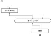
- FIG. 1 is a diagram illustrating a configuration of an embodiment of a system including a terminal to which the present technology is applied.
- the system shown in FIG. 1 includes a store server 11, a terminal 12, and a network 13.
- the system shown in FIG. 1 is a system related to a case where a predetermined application is downloaded from the store server 11 to the terminal 12 via the network 13 and the downloaded application is activated (used) in the terminal 12. .
- the store server 11 is a device that distributes applications.
- the application may be distributed free of charge or may be distributed for a fee.
- the terminal 12 is a personal computer, a mobile phone (including a smartphone), a mobile terminal (including a device attached to a part of a body or clothes, a device stored in a bag, or the like).
- the network 13 is composed of wired, wireless, Internet, LAN (Local Area Network) or the like, and the store server 11 and the terminal 12 are configured to be able to exchange data (applications) via the network 13.
- LAN Local Area Network
- FIG. 2 is a diagram for explaining the configuration (function) of the terminal 12.
- the terminal 12 downloads a predetermined application from the store server 11 and executes processing based on the downloaded predetermined application.
- the description will be continued on the assumption that the data is downloaded from the store server 11 and processed on the terminal 12 side, but a cloud system or the like can also be applied, and the present technology can be applied even when the cloud system or the like is applied. it can.
- the description will be continued by taking as an example a case where the predetermined application downloaded to the terminal 12 side is an application that performs processing using data from sensors provided in the terminal 12. Further, a case where the application recognizes (determines) the user's behavior using data from the sensor will be described as an example.
- the user's action is, for example, an action such as riding on a vehicle, walking, or stopping (sleeping or sitting).
- a user's action includes a gesture.
- the application is one or more applications that execute processing for discriminating these actions.
- the application also includes an application that performs processing using the determined user behavior, for example, processing for determining the coordinates of a destination that has moved as a result of the user walking.
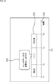
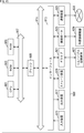
- the terminal 12 shown in FIG. 2 includes a sensor 51, a checker 52, a recognition unit 53, a determination unit 54, a storage unit 55, a display control unit 56, and a display unit 57.
- the sensor 51 is an acceleration sensor, a gyro sensor, a touch sensor, or the like. Sensors such as a thermometer and a barometer may be included.
- the checker 52 checks items related to the accuracy of the sensor 51.
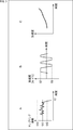
- the check item as the accuracy of the sensor 51 is, for example, an item for checking an object as shown in FIG.
- FIG. 3A shows a case where a time stamp error is targeted.
- the vertical axis of the graph shown in FIG. 3A represents the sampling period, and the horizontal axis represents the elapsed time.
- the sampling period is a sampling period (desired sampling period) in which the reference value th1 indicated by a solid line in A of FIG. 3 is correct.
- a value smaller than the reference value th1 around the reference value th1 is set as a threshold value th2, and a value larger than the threshold value th1 is set as a threshold value th3.
- the sampling frequency is greater than or equal to the threshold th2 and less than or equal to the threshold th3, the period is within the allowable range, and it is determined that the sampling frequency is normal. However, for example, when the sampling frequency is equal to or lower than the threshold th2 as at time t1 in FIG. 3A, it is determined that the sampling frequency is not normal. Whether or not such a desired sampling frequency is satisfied is set as one of the evaluation items related to the accuracy of the sensor 51 and checked.
- the accuracy required for the sampling frequency may vary depending on the application.
- the threshold values may be different depending on the application.
- the sampling frequency at the time of determination is within the range required for application A, but may be outside the range required for application B. Therefore, the determination is performed using the allowable range of the sampling frequency suitable for the application.
- FIG. 3B shows a case where a value abnormality is targeted.
- a measurement range may be set for the sensor 51.
- FIG. 3B shows a case where the measurement range of the acceleration sensor is R1 or more and R2 or less, for example. When the acceleration measured by the acceleration sensor is below the range R1 or above the range R2, the measurement range is insufficient, the value is saturated, and a correct measurement result is not output.
- the measurement value is outside the measurement range of the acceleration sensor, and the value may be saturated. In such a case, it is determined that the value from the acceleration sensor is abnormal (possibly not normal). Whether or not measurement is performed within such a measurement range is set as one of the evaluation items related to the accuracy of the sensor 51 and checked.
- 3C shows a case where a value abnormality is targeted. Due to the offset fluctuation of the sensor 51, the value from the sensor 51 may be abnormal. For example, it is assumed that the terminal 12 including the acceleration sensor is placed on a desk and is stationary. In such a state, the value from the acceleration sensor is 0, but as shown in FIG. 3C, the value fluctuates although it is stationary, in other words, the value should be 0. Nevertheless, the value may fluctuate.
- offset fluctuation is one of the evaluation items related to the accuracy of the sensor 51 and is checked. Whether or not the acceleration sensor fluctuates in offset is determined, for example, when the gyro sensor determines that the position is not moving, and when the accelerometer determines that the position is moving, the acceleration sensor fluctuates in offset. Can be determined. As described above, it is possible to detect an abnormality of one or a plurality of sensors using data from a plurality of sensors, and the detection of such an abnormality can also be used to detect the accuracy of the sensor 51.
- the checker 52 detects (checks) the abnormality of the sensor 51 as described above, and outputs the detection result to the determination unit 54.
- the determination unit 54 determines whether an abnormality has occurred in the sensor 51 using the detection result from the checker 52. For example, the reliability of the sensor 51 is calculated by the detection by the checker 52 and the determination by the determination unit 54.
- the reliability of the sensor 51 is a value indicating how reliable the value obtained by the sensor 51 is when a predetermined application is operated. For example, when the number of times a time stamp abnormality is detected is high, the reliability is calculated low, and when the number is low, the reliability is calculated high. The reliability can be calculated based on the above.
- the degree of how far away from the allowable range is calculated, and the reliability can be calculated based on that value.
- the reliability is calculated to be low.
- the reliability may be calculated based on the points.
- the determination result from the determination unit 54 is supplied to the storage unit 55 and the display control unit 56.
- a recognition result from the recognition unit 53 is also supplied to the storage unit 55 and the display control unit 56.
- the recognition unit 53 recognizes the user's action using the sensing result obtained from the sensor 51. For example, using the result obtained from the acceleration sensor, it can be determined whether it is in a moving state or in a stationary state, or even when it is walking or riding a vehicle. To determine if it exists.
- Such a determination result is output to the storage unit 55 and the display control unit 56 as a recognition result of the recognized user action.
- the description is continued assuming that the user's action is recognized as being in a walking state or in a vehicle, but as a result of the user's action, for example, Recognize the coordinates of the destination when the user's position has moved by walking the user, or recognize the contents (gesture contents) specified by the user as a result of the user's movement of the hand
- the recognition unit 53 also performs.
- the recognition unit 53 performs processing based on a predetermined recognition algorithm.
- the predetermined recognition algorithm differs depending on the behavior recognized by the predetermined application. As described above, the accuracy required for the sensor 51 differs depending on the recognition algorithm.
- the storage unit 55 stores the determination result from the determination unit 54 and the recognition result from the recognition unit 53 in association with each other.
- the determination result is information indicating whether or not the sensor 51 is normal
- the recognition result is information indicating the result recognized as the user's action. Such information is associated and stored in the storage unit 55.
- the determination result and the recognition result stored in the storage unit 55 are appropriately described as a log.
- the display control unit 56 performs processing for causing the display unit 57 to display the determination result from the determination unit 54 and the recognition result from the recognition unit 53. Alternatively, the display control unit 56 performs a process for causing the display unit 57 to display the determination result and the recognition result stored in the storage unit 55.
- the display control unit 56 When displaying the recognition result on the display unit 57 in real time, the display control unit 56 performs a process for causing the display unit 57 to display the determination result from the determination unit 54 and the recognition result from the recognition unit 53. When displaying past recognition results on the display unit 57, the display control unit 56 performs processing for causing the display unit 57 to display the determination results and the recognition results stored in the storage unit 55.
- the screen displayed on the display unit 57 is a display in which the recognition result is associated with whether the recognition result is correct (whether the accuracy of the recognition result may be low). Since the accuracy of the sensor 51 is lowered, the display may be made to allow the user to recognize that the accuracy of the recognition result may be lowered.
- step S11 the terminal 12 downloads the application from the store server 11.
- a process may be performed in which an application that will operate comfortably is recommended depending on the accuracy of the terminal 12, particularly the accuracy of the sensor.
- the accuracy (reliability) of the sensor 51 can be calculated, and an application can be recommended based on the accuracy.
- step S12 the terminal 12 activates the downloaded application and makes it ready for use. For example, in the case of an application that leaves (stores) user actions as a log, the log recording is started by being activated.
- a process for determining whether or not the terminal 12 (sensor 51) operates comfortably may be executed before the use of the application is started.
- the accuracy (reliability) of the sensor 51 can be calculated by providing the checker 52 and the determination unit 54 in the terminal 12, and the accuracy is required for the application by calculating the accuracy before the use of the application is started. It is possible to determine whether or not the sensor 51 (terminal 12) has the accuracy to be determined.
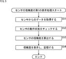
- step S51 the checker 52 acquires data from the sensor 51.
- step S ⁇ b> 52 the checker 52 checks the operation state of the sensor 51 and outputs the result to the determination unit 54.
- step S53 the determination unit 54 determines whether or not an abnormality has occurred in the sensor 51 using the result from the checker 52, and calculates the reliability of the sensor 51 at that time.
- the processing load increases, and the processing in the sensor 51 can be performed. There may be no state.
- the processing load is reduced, and the sensor 51 can output data at a sampling cycle within an allowable range. May increase reliability.
- the reliability of the sensor 51 may change depending on the state of the terminal 12 at that time, the reliability of the sensor 51 at the time when the data from the sensor 51 is acquired is calculated. If the sampling frequency is outside the allowable range, data from the sensor 51 may not be acquired in step S51, and the reliability may not be calculated.
- the reliability is calculated (the processing of the flowchart shown in FIG. 5 is started) when the data from the sensor 51 is acquired, and at a predetermined cycle, for example, Alternatively, it may be calculated for each sampling period. Alternatively, the reliability may be calculated at a predetermined cycle, for example, every sampling cycle, regardless of whether data from the sensor 51 is acquired. The same applies to the following description.
- the determination result (reliability) determined by the determination unit 54 in step S53 is supplied to the storage unit 55 and the display control unit 56.
- the display control unit 56 performs control for displaying the reliability on the display unit 57, and the storage unit 55 stores the reliability. It should be noted that while the processing relating to such display is being executed, recognition processing relating to user behavior is executed by the recognition unit 53, and the recognition result recognized by the recognition processing is stored in the storage unit 55 together with the reliability. Is done.
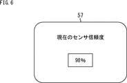
- FIG. 6 to 8 show an example of the reliability displayed on the display unit 57.
- FIG. The display example shown in FIG. 6 is an example in which the reliability is displayed as a numerical value.
- a message “Current sensor reliability” is displayed, and a numerical value expressed as a percentage “98%” is displayed. By displaying the message, the user can recognize the reliability of the sensor 51 and can recognize that the reliability is “98%”.
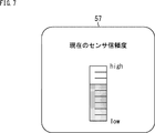
- the display example shown in FIG. 7 is an example in which the reliability is represented by an indicator.
- a message “Current sensor reliability” is displayed, and an indicator is displayed below the message.
- the display example shown in FIG. 8 is an example in which the reliability is expressed in time series.
- the display example shown in FIG. 8 differs from the display examples shown in FIGS. 6 and 7 in that not only the reliability of the sensor at that time but also the reliability of the sensor from the time before that time is continuously displayed.
- the display is shown.
- a message “Current sensor reliability” is displayed, and a graph is displayed below the message.
- the vertical axis of the displayed graph represents reliability
- the horizontal axis represents time.
- Such a display may be displayed on a predetermined area such as the upper right of the screen, for example, which is always displayed on the screen of the display unit 57, or there is an instruction from the user. Sometimes displayed, for example, in a pop-up window.
- steps S71 to S73 in the flowchart shown in FIG. 9 are the same as steps S51 to S53 in the flowchart shown in FIG.
- the reliability is calculated in step S73, it is determined in step S74 whether or not there is a display instruction from the user.
- step S74 If it is determined in step S74 that there is a display instruction from the user, the reliability is displayed and stored in step S75.
- This display is performed by the same processing as step S54 in the flowchart shown in FIG. 5, and the screens as shown in FIGS. 6 to 8 are displayed in, for example, a pop-up window.
- step S76 if it is determined in step S74 that there is no display instruction from the user, reliability is stored in step S76.
- the reliability may be displayed and stored when the user gives an instruction, and may be stored when there is no user instruction.
- the recognition unit 53 is executing the recognition process related to the user's action.
- the reliability When the reliability falls below a predetermined value, the reliability may be displayed to notify the user of that fact. When the reliability falls below a predetermined value, by notifying the user of that fact, the user is allowed to execute some processing, for example, processing such as stopping the activated application, at the user's discretion. Can do.
- the reliability when the reliability is displayed to notify the user when the reliability falls below a predetermined value, the reliability itself is represented as shown in FIGS. Instead of being displayed, a message for recognizing that the reliability is lowered may be displayed. A case where a display for notifying the user of such a reliability when the reliability falls below a predetermined value will be described below.
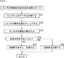
- step S 10 can be performed in the same manner as steps S51 to S53 in the flowchart shown in FIG. 5, and thus the description thereof is omitted here.
- the determination unit 54 determines whether or not the calculated reliability is equal to or less than a predetermined threshold value.
- step S114 If it is determined in step S114 that the reliability is not less than or equal to the predetermined threshold, in other words, the accuracy of the sensor 51 is the accuracy that does not interfere with the normal operation of the application (necessary for outputting an accurate recognition result). If it is determined that (accuracy), the process returns to step S111, and the subsequent processes are repeated. When the reliability is calculated, the reliability is associated with the recognition result from the recognition unit 53 and stored in the storage unit 55.
- step S114 if it is determined in step S114 that the reliability is equal to or lower than the threshold value, in other words, the accuracy of the sensor 51 is the accuracy that hinders the normal operation of the application (accuracy that may output an erroneous recognition result). If it is determined that, the process proceeds to step S115.
- step S115 a process for displaying the reliability (alert) on the display unit 57 is executed by the display control unit 56.
- the screen displayed on the display unit 57 in the process in step S115 may be any of the screens shown in FIGS.
- the reliability may be presented to the user by a numerical value, an indicator, a graph, or the like to inform the user that the accuracy of the sensor 51 has dropped.
- step S115 when the accuracy of the sensor 51 is determined to be an accuracy that hinders the normal operation of the application. Therefore, the accuracy of the sensor 51 is not a screen showing the reliability as a numerical value. For example, it may be a screen on which a message is displayed so as to make the user recognize that the image has fallen.
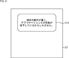
- a message as shown in FIG. 11 is displayed.
- a window 111 is displayed in a predetermined area of the display unit 57, and a message such as “the terminal operation is heavy and the performance of the application A may be degraded” is displayed in the window 111.
- This message is a message that allows the user to recognize that the application (application A) is operating normally, but the processing load on the terminal 12 is increasing, so that the performance of the application A is degraded. is there.
- the application A is an application that performs action recognition
- the action recognition itself by the application A is executed, but the data from the sensor 51 is jittery and cannot be acquired, or is outside the measurement range.
- the user recognizes this when the accuracy of action recognition of the application A that performs processing using the data from the sensor 51 is reduced. Message.
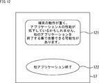
- a window 121 is displayed in a predetermined area of the display unit 57.
- “the operation of the terminal is heavy and the performance of the application A may be degraded.
- Message is displayed.
- a message such as “There is a possibility of improvement by closing another application” is also displayed.
- the user reads such a message and operates the button 122 displayed in the lower area of the window 121 when desiring to take a countermeasure for terminating another application.
- the button 122 displays a message such as “end other application”, and the user can recognize that the other application can be ended by operating the button 122 by viewing this message. it can.
- buttons 122 When the user operates the button 122, applications other than the application A are terminated. When a plurality of applications other than the application A are activated, a list of the activated applications may be displayed so that the user can select an application desired to be terminated.
- a message for recognizing that an abnormality has occurred in the sensor 51 (terminal 12) and a message regarding countermeasures for eliminating the abnormality are displayed.
- the button 122 is also displayed, so that the user can easily take the countermeasure and the usability can be improved.
- a message for recognizing that an abnormality has occurred in the sensor 51 (terminal 12) is not displayed, and only a message regarding countermeasures for eliminating the abnormality is displayed in the window 121. It is also possible to make it.
- the message displayed in the window 121 is not limited to the message shown in FIG.
- messages as shown in FIGS. 13 and 14 may be used.
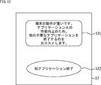
- a window 131 is displayed in a predetermined area of the display unit 57, and “the operation of the terminal is heavy in the window 131. Other unnecessary for improving the performance of the application A”. I recommend that you quit any other applications. "
- a window 141 is displayed in a predetermined area of the display unit 57, and “terminal operation is heavy in the window 141. If the operation of application A is not correct, May be improved by closing unnecessary applications. "Message is displayed.
- the message may be any word, but a message for causing the user to recognize an abnormality (such as a decrease in performance) of the sensor 51 (terminal 12) is displayed. Further, countermeasures may be further displayed. Further, when executing the countermeasure, a message, a button, or the like that helps the user may be displayed.
- step S115 processing for causing such a message or button to be displayed on the display unit 57 is executed.
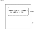
- a window 151 is displayed in a predetermined area of the display unit 57, and a message such as “The terminal cannot sufficiently secure the performance of application A” is displayed in the window 151. Has been.
- the user can recognize that there is no problem in the application and that a problem has occurred on the terminal 12 (hardware) side. Therefore, it can prevent that evaluation with respect to an application falls.
- the terminal 12 (application A) recognizes the user's behavior and supplies the recognition result to the storage unit 55 and the display control unit 56.
- a description will be given of a case where the reliability of the sensor 51 described above is provided to the user together with the recognition result.
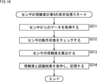
- Steps S211 to S213 in the flowchart shown in FIG. 16 are the same as steps S51 to S53 in the flowchart shown in FIG.
- step S213 When the reliability is calculated in step S213, the display control unit 56 starts control for displaying the reliability and the recognition result on the display unit 57 in step S214, and the storage unit 55 recognizes the reliability. Associate and store the results.
- FIGS. Examples of screens displayed on the display unit 57 in the process of step S214 are shown in FIGS.
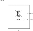
- a picture display area 211 where a picture is displayed and an action display area 212 where an action recognition result is displayed are provided on the display unit 57.
- the behavior display area 212 the behavior recognized by the processing of the application A as being performed by the user at that time is displayed.
- the action (recognition result) displayed in the action display area 212 may not be accurate due to abnormality of the sensor 51 or the like, a picture representing the terminal 12 is displayed in the picture display area 211.
- a picture representing the terminal 12 is displayed in the picture display area 211 to indicate that the recognition result is in a state where an abnormality has occurred on the terminal 12 side.
- a cross mark is superimposed on the picture, and the fact that there is a possibility that an abnormality has occurred in the terminal 12 is emphasized.
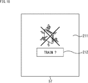
- the display example shown in FIG. 18 is basically the same as the display example shown in FIG. 17, but the picture displayed in the picture display area 211 is different.
- a picture representing the sensor 51 is displayed in the picture display area 211, and a picture on which a cross mark is superimposed is displayed.
- the image may be a picture that allows the user to recognize that there is a possibility that an abnormality has occurred in the sensor 51.
- the recognition result displayed in the action display area 212 is a result recognized by the recognition unit 53 (FIG. 2). Also displayed in the action display area 212? The mark is displayed when the reliability is low based on the determination result by the determination unit 54. Similarly, a picture is displayed in the picture display area 211 when the reliability is determined to be low based on the determination result by the determination unit 54.
- the recognition result displayed in the behavior display area 212 is not a highly accurate recognition result due to abnormality of the terminal 12 (sensor 51)
- the recognition result displayed in the behavior display area 212 is To?
- the mark is displayed.
- a picture that allows the terminal 12 and the sensor 51 to be intuitively recognized is displayed in a state where a cross mark is superimposed.
- a picture representing the terminal 12 (sensor 51) is displayed in the picture display area 211, but a cross may not be displayed.
- a message may be displayed instead of a picture.
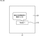
- 20 and 21 respectively show display examples in which messages are displayed.
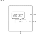
- the display unit 57 is provided with a message display area 221 where a message is displayed and an action display area 212 where an action recognition result is displayed.
- the recognition result recognized by the application A is displayed in the same manner as the behavior display area 212 shown in FIGS.
- the action (recognition result) displayed in the action display area 212 may not be accurate due to abnormality of the sensor 51 or the like, a message for causing the user to recognize this is displayed in the message display area 221.
- the message “Due to an increase in processing load on the terminal” is displayed in the message display area 221. That is, in the display example shown in FIG. A mark is displayed, and the reason why the accuracy of the recognition result may be low is displayed in the message display area 221.
- a message indicating countermeasures may be displayed.
- a message “Do you want to diagnose sensor data?” Is displayed in the message display area 221.
- this message the button on which the message is displayed.
- “Sensor data diagnosis” is executed.
- “Sensor data diagnosis” is a process for diagnosing the accuracy (reliability) of the sensor 51, which will be described later. This is a diagnosis that is executed when
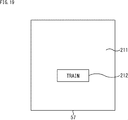
- the display such as “TRAIN” displayed in the action display area 212 is lightly displayed. It is expressed that there is a possibility that the accuracy of the recognition result is low by displaying lightly. In this way, if there is a possibility that the accuracy of the recognition result is low, such as reducing the display? You may make it display by the display methods other than displaying a mark.
- step S214 In the process of step S214 (FIG. 16), one of the displays shown in FIGS. 17 to 21 is performed.
- the display example shown here is an example, and another display may be performed.
- Such a display may be always displayed on the screen of the display unit 57, for example, or displayed when there is an instruction from the user, for example, displayed in a pop-up window.
- steps S251 to S253 in the flowchart shown in FIG. 22 are the same as steps S51 to S53 in the flowchart shown in FIG.
- the reliability is calculated in step S253
- step S254 If it is determined in step S254 that there is a display instruction from the user, the reliability and the recognition result are displayed and stored in step S255.
- This display is the same processing as step S214 in the flowchart shown in FIG. 16, and the screens shown in FIGS. 17 to 21 (except for FIG. 19) are displayed in a pop-up window, for example.
- step S254 when it is determined in step S254 that there is no display instruction from the user, the reliability and the recognition result are stored in step S256. As described above, the reliability and the recognition result may be displayed and stored when the user gives an instruction, and may be stored when there is no user instruction.
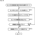
- step S311 it is determined whether or not there is an instruction to read the log stored in the storage unit 55. In step S311, the process in step S311 is repeated (the standby state is maintained) until it is determined that the log reading is instructed.
- step S311 determines whether reading of the log is instructed. If it is determined in step S311 that reading of the log is instructed, the process proceeds to step S312.
- step S312 logs are sequentially read from the storage unit 55.
- the read log can be a log from a time designated by the user or a log from before the time designated by the user.
- step S313 it is determined whether or not the reliability included in the read log is equal to or less than a threshold value. If it is determined in step S313 that the reliability included in the read log is not equal to or less than the threshold, the process proceeds to step S314. If it is determined that the reliability is equal to or less than the threshold, the process proceeds to step S315. It is done.
- step S314 normal display is performed.
- step S315 display with an alert is performed. Screens displayed by such processing will be described with reference to FIGS.
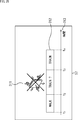
- the display unit 57 is provided with a picture display area 311 for displaying pictures, an action display area 312 for displaying action recognition results, and a time axis display area 313 for displaying a time axis. ing. In this screen configuration, a time axis display region 313 is added to the screen configuration shown in FIG.
- the time axis display area 313 displays the time axis, and the action recognized by the processing of the application A as being performed by the user in the time zone represented by the time axis is displayed in the action display area 312.
- the behavior (recognition result) displayed in the behavior display area 312 may not be accurate due to abnormality of the sensor 51 or the like, a picture representing the terminal 12 is displayed in the picture display area 311.
- step S312 the log corresponding to the time t1 to the time t2 is read from the storage unit 55.
- step S313 it is determined that the reliability included in the read log is not equal to or less than the threshold value, the process proceeds to step S314, and normal display is performed. What is normal display? What is the recognition result displayed in the action display area 312? This is a display in which no mark is displayed or lightly displayed, and no picture is displayed in the picture display area 311.
- step S312 logs corresponding to the time t2 to the time t3 are read from the storage unit 55.
- step S313 it is determined that the reliability included in the read log is equal to or less than the threshold value, and the process proceeds to step S315 to display with an alert. What is the display with an alert? What is the recognition result displayed in the action display area 312? A mark is displayed or displayed lightly, and a picture in which a cross is superimposed on a picture representing the terminal 12 or the sensor 51 is displayed in the picture display area 311.
- the display example shown in FIG. 25 is basically the same as the display example shown in FIG. 24, but the pictures displayed in the picture display area 311 are different.
- a picture representing the sensor 51 is displayed in the picture display area 211, and a picture on which a cross mark is superimposed is displayed.
- the image may be a picture that allows the user to recognize that there is a possibility that an abnormality has occurred in the sensor 51.
- the terminal 12 when the terminal 12 (sensor 51) has an abnormality and when it has not occurred, the terminal 12 (sensor 51) has an abnormality in the user by displaying differently. It is possible to clearly recognize whether or not it is time.
- FIG. 26 and FIG. 27 respectively show display examples in which messages are displayed.
- the display unit 57 includes a message display area 321 where a message is displayed, an action display area 312 where an action recognition result is displayed, and a time axis display area 313 where a time axis is displayed. It has been.
- the action display area 312 and the time axis display area 313 display the recognition result recognized by the application A and the time axis, respectively.
- the action (recognition result) displayed in the action display area 312 may not be accurate due to abnormality of the sensor 51 or the like, a message that causes the user to recognize this is displayed in the message display area 321.
- a message “Due to an increase in processing load on the terminal” is displayed in the message display area 321.
- the reason why the mark is displayed and the accuracy of the recognition result may be low is displayed as a message in the message display area 321.
- a message indicating countermeasures may be displayed.
- a message “Do you want to diagnose sensor data?” Is displayed in the message display area 321.
- this message the button on which the message is displayed) ) Is operated.
- “Sensor data diagnosis” is executed.
- “Sensor data diagnosis” is a process for diagnosing the accuracy (reliability) of the sensor 51, which will be described later. This is a diagnosis that is executed when
- the senor 51 may be reset by performing such a diagnosis, and it may be possible to return the accuracy of the sensor 51 by resetting. Therefore, an abnormality has occurred in the sensor 51 at the past time point, and the user is made aware of this, and a message “Do you want to diagnose the sensor data?” Is displayed to make the diagnosis at the present time.
- the sensor 51 can be reset.
- the display “TRAIN” displayed in the action display area 312 is displayed lightly in the time zone corresponding to the time t2 to the time t3. It is expressed that there is a possibility that the accuracy of the recognition result is low by displaying lightly. In this way, if there is a possibility that the accuracy of the recognition result is low, such as reducing the display? You may make it display by the display methods other than displaying a mark.
- the screens as shown in FIGS. 24 to 27 are displayed on the display unit 57 by the processing in steps S314 and S315 (FIG. 23).
- the display example shown here is an example, and another display may be performed.
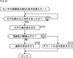
- step S353 If it is determined in step S353 that the reliability included in the read log is equal to or lower than the threshold, the process proceeds to step S355. In step S355, it is determined whether or not the state where the reliability is determined to be equal to or less than the threshold is continuous.
- step S355 when it is determined that the state in which the reliability is determined to be equal to or less than the threshold value is continuous, the process proceeds to step S356, and display with an alert corresponding to the number of consecutive times is performed. If it is determined that it has not, the process proceeds to step S357, and a display with an alert is performed.
- FIG. 29 shows a display example displayed on the display unit 57. 29 is displayed in the action display area 312 in the display example shown in FIG. 27, for example.
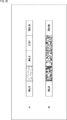
- the actions “WALK”, “WALK?”, “WALK”, “STAY”, and “TRAIN” are displayed in this order as the result of action recognition. Since the second action recognition result may have been acquired when the accuracy of the sensor 51 is low, “WALK?” Is displayed, and is colored and displayed so as to be distinguished from other recognition results. Has been.
- step S353 when the log regarding the second action recognition is processed, it is determined in step S353 that the reliability is equal to or lower than the threshold value, and the process proceeds to step S355.
- step S355 it is determined that the state where the reliability is determined to be equal to or less than the threshold value is not continuous, and the process proceeds to step S357.
- step S357 display with an alert is performed. What is this display with alerts?
- the mark is displayed, the color is displayed in a color different from other recognition results (including a light display), and the like, for example, is a display with an alert described with reference to FIGS.
- FIG. 29 it is of course possible to display a picture or message in which a cross mark is superimposed on the picture of the terminal. Is possible.
- step S353 When the log relating to the third action recognition is processed, it is determined in step S353 that the reliability is not less than or equal to the threshold value, and the process proceeds to step S354.
- step S354 since normal display is performed, as shown in FIG. 29A, “WALK” is displayed without an alert.
- actions “WALK”, “WALK?”, “WALK?”, “STAY?”, “TRAIN” are displayed in this order. ing. Since the second, third, and fourth action recognition results may be obtained when the accuracy of the sensor 51 is low, “WALK?”, “WALK?”, “STAY?” Are displayed. It is displayed with a color so that it can be distinguished from other recognition results.
- This color is different from the second, third and fourth.
- the color is gradually darkened.
- the third recognition result is displayed in a darker color than the second recognition result, and the fourth recognition result is displayed in a darker color than the third recognition result.
- gradually darkening is an example, and other coloring methods may be used.
- By gradually increasing the color it is possible to give the user a feeling that the degree of danger increases.
- By gradually fading the color it is possible to make the user recognize that the reliability of the sensor 51 is low and the reliability of the recognition result has been reduced.
- the period when the reliability is low (the number of times that the state where the reliability is determined to be equal to or less than the threshold is continuous )
- the display color may be different.
- the color of the three sections shown in B of FIG. 30 is darker than the color of the one section shown in A of FIG.
- one section shown in FIG. 30A can be light red
- three sections shown in FIG. 30B can be dark red.
- the severity can be expressed by the color (display).
- step S353 when the log related to the second action recognition is processed, it is determined in step S353 that the reliability is equal to or lower than the threshold value, and the process proceeds to step S355. Processing proceeds. In step S355, it is determined that the state where the reliability is determined to be equal to or less than the threshold value is not continuous, and the process proceeds to step S357. In step S357, display with an alert is performed.
- step S353 When the log regarding the third action recognition is processed, it is determined in step S353 that the reliability is equal to or lower than the threshold value, and the process proceeds to step S355. In step S355, it is determined that the state in which it is determined that the reliability is equal to or less than the threshold is continuous, and the process proceeds to step S356.
- step S356 display with an alert corresponding to the number of consecutive times is performed.
- a display with an alert corresponding to the second time for example, as shown in FIG. 29B
- the third recognition result is darker than the second recognition result.
- a display with an alert is displayed in which the second recognition result and the third recognition result are displayed in the color when the number of consecutive times is two.
- step S353 it is determined that the reliability is equal to or lower than the threshold value, and the process proceeds to step S355.
- step S355 it is determined that the state in which it is determined that the reliability is equal to or less than the threshold is continuous, and the process proceeds to step S356.
- step S356 display with an alert corresponding to the number of consecutive times is performed.
- the display with an alert corresponding to the 3 times for example, as shown in FIG. 29B
- the fourth recognition result is darker than the third recognition result. Is displayed with an alert.
- the display with the alert that displays the second, third, and fourth recognition results is performed in the color when the number of consecutive times is three.
- step S353 When the log relating to the fifth action recognition is processed, it is determined in step S353 that the reliability is not less than or equal to the threshold value, and the process proceeds to step S354.
- step S354 since normal display is performed, as shown in FIG. 29B or FIG. 30B, “TRAIN” is displayed with no alert.
- the message shown in FIG. 26 or 27 may be displayed.
- the display example displayed in the message display area 321 shown in FIG. 26 is applied to the display example displayed in the action display area 212 shown in FIG.
- the reason “due to an increase in processing load” may be displayed.
- a message may be displayed on each of the second, third, and fourth recognition results, or one message may be displayed. .
- the button “display reason” is displayed first, and the reason is displayed when the button is operated. You may do it.
- the display example displayed in the message display area 321 shown in FIG. 27 is applied to the display example displayed in the action display area 212 shown in FIG. You may make it display the countermeasure "Do you want to diagnose sensor data?"
- a message may be displayed on each of the second, third, and fourth recognition results, or one message may be displayed.
- a message such as “Do you want to diagnose sensor data?” Is displayed. It may be displayed.
- a message indicating the reason as shown in FIG. 26 is displayed.
- a message indicating a countermeasure as shown in FIG. may be different.
- the sensor 51 when the reliability of the sensor 51 is low, for example, as shown in FIG.
- the sensor 51 is shown to have low reliability by adding marks or displaying thinly.
- the action of walking (WALK) is recognized as the action of the user such as “WALK?”, But the recognition result may be incorrect because the reliability of the sensor 51 is low. Represents a state.
- a recognition result may be output by the recognition unit 53.
- a display such as “INVALID” is made. You may do it.
- the display with an alert as described above may be used, but words and words other than the word representing the action, for example, words and words such as “INVALID” and “undecided due to reduced accuracy” are displayed.
- words and words other than the word representing the action for example, words and words such as “INVALID” and “undecided due to reduced accuracy” are displayed.
- words and words other than the word representing the action for example, words and words such as “INVALID” and “undecided due to reduced accuracy” are displayed.
- words and words other than the word representing the action for example, words and words such as “INVALID” and “undecided due to reduced accuracy” are displayed.
- such a word or wording may be displayed together with the display with an alert described above.
- a mechanism can be provided in which the action recognition on which the alert is displayed can be corrected by the user. For example? When a recognition result displayed with a mark attached is operated, a mechanism may be provided in which the screen is switched to a screen on which the recognition result can be corrected and the recognition result is corrected.
- application A a predetermined application
- application B another application
- the accuracy required for the sensor 51 is different.
- a plurality of applications that perform processing using the sensor 51 may be operating simultaneously.
- the data from the sensor 51 may be used not only by one application but by a plurality of applications.
- the required accuracy of the sensor 51 is maintained for the application A. In some cases, the accuracy of the required sensor 51 is not maintained for the application B.
- the allowable accuracy differs for each application.
- Application) OK
- NG application that performs autonomous positioning
- NG may be determined.
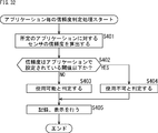
- the reliability of the sensor 51 can be calculated for each application, and the reliability can be presented to the user for each application. The processing for such presentation will be described with reference to the flowchart shown in FIG.
- step S401 the reliability of the sensor 51 for a predetermined application is calculated. This calculation of reliability can be performed in the same manner as described above. In addition, the reliability may be calculated only for a sensor included in the sensor 51 and used by an application that is a processing target among a plurality of sensors.
- step S402 it is determined whether or not the reliability is equal to or less than a threshold set by the application.
- a threshold set in the application is set such that the sampling frequency is preferably A or more and the measurement range is preferably B or more, the value is used as the threshold. it can.
- step S402 If it is determined in step S402 that the reliability is not less than or equal to the threshold set by the application, the process proceeds to step S403, and it is determined that the reliability can be used. On the other hand, when it is determined in step S402 that the reliability is equal to or lower than the threshold set by the application, the process proceeds to step S404, and it is determined that the reliability cannot be used.
- step S405 Such a determination result is displayed or stored. That is, in step S405, the determination result is stored in the storage unit 55 and displayed on the display unit 57 as necessary.
- the accuracy of the sensor 51 indicates to the user whether or not the predetermined application is in a usable state. Can do.
- two determination results that can be used or cannot be used may be output.
- two determination results such as “comfortably operate”, “operate”, “difficult to operate”, and “do not operate” may be output.
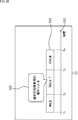
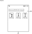
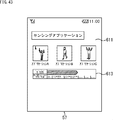
- the display unit 57 is provided with an application list display area 411 for displaying applications.
- the application list display area 411 among the applications classified for each category, applications that match the category are displayed.
- an application belonging to a sensing application that performs processing using data from the sensor 51 is displayed.
- the application being displayed means that the name of the application, an icon representing the application, and the like are displayed.
- names and icons (pictures) of application A, application B, and application C belonging to the sensing application are displayed.
- An application that is not displayed is configured to be displayed when an operation such as a slide is performed.
- the icon representing the application C is displayed with a cross mark superimposed thereon.
- the cross mark is not superimposed on the icons representing the applications A and B, respectively.
- the accuracy of the sensor 51 is sufficiently obtained in the application A and the application B, and it is determined that the sensor 51 can be used, and the accuracy of the sensor 51 cannot be sufficiently obtained in the application C. This is a state when it is determined that it cannot be used.
- a list of a plurality of applications that perform processing using the sensor 51 is displayed.
- a display indicating that. For example, a cross mark is superimposed and displayed.
- Such display may be performed when the user gives an instruction, or may be always displayed in a predetermined area of the display unit 57.
- the processing of the flowchart shown in FIG. 32 is executed when the user instructs display (application list display) as shown in FIG. 33, and the accuracy of the sensor 51 at that time is measured and usable.
- an unusable application is determined for each application and displayed together with the determination result.
- the processing of the flowchart shown in FIG. 32 is executed at predetermined intervals, the accuracy of the sensor 51 at the time of execution is measured, and usable or unusable applications are determined for each application. Based on the determination result, the list of displayed applications may be updated so that the user is always presented to the user.
- the accuracy of the sensor 51 at the time of execution is stored in the storage unit 55 as a log, and the user can display (
- the application list display is instructed, the stored log may be referred to and the application list displayed. In this case, a list of applications may be displayed by referring to the latest log.
- the accuracy (reliability) of the sensor 51 is left as a log
- learning using the log may be performed.
- a log is referred to, an average of reliability of the sensor 51 is calculated, and when the average value is equal to or lower than a predetermined threshold, it is determined that it cannot be used, and a display indicating that it cannot be used is performed.
- the number of times that the accuracy of the sensor 51 is determined to be low is left as a log, and the number of times that the accuracy of the sensor 51 is determined to be low is calculated for each application by referring to the log.
- the predetermined number of times it may be determined that use is not possible, and a display indicating that use is not possible may be performed.
- ⁇ Reliability threshold setting> As described above, according to the present technology, when the accuracy (reliability) of the sensor 51 (terminal 12) is lowered, this can be presented to the user. Whether to present (whether to display an alert or whether to display with an alert) is determined by determining whether the reliability is equal to or lower than a predetermined threshold.
- this threshold value may be different for each application, and may be set for each application. Alternatively, processing can be performed using one threshold value.
- a threshold value may be set by the user.
- the threshold is set high, the reliability is often less than or equal to the threshold, and the number of times the alert is displayed may increase. Therefore, by setting the threshold value by the user, the user can set the number of times (possibility) that the alert is displayed by the user.
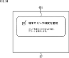
- FIG. 34 is an example of a screen displayed on the display unit 57 when the user sets a threshold value.
- a threshold value setting screen 451 is displayed on the display unit 57.
- a check column is displayed in the threshold value setting screen 451, and a message “Monitor sensor accuracy of terminal” is displayed on the right side of the check column.
- a message such as “Display alert when sensor accuracy is insufficient” is displayed below the message.
- the user can check the accuracy of the sensor 51 of the terminal 12 by checking the check column by referring to the threshold setting screen 451, and when the accuracy of the sensor 51 is not sufficient, It can be recognized that an alert for recognizing is displayed.
- the threshold setting screen 451 when the user refers to such a threshold setting screen 451 and does not check the check column, for example, as described above, when the reliability is calculated and the reliability falls below the threshold, an alert is displayed.
- the process displayed on the part 57 is not executed, and no alert is displayed.
- the threshold when the alert is displayed may be set to a low threshold, and for example, the alert may be displayed only when the accuracy of the sensor 51 is reduced to the extent that the application cannot operate.
- the alert may be displayed.
- FIG. 35 is another example of a screen displayed on the display unit 57 when the user sets a threshold value.
- a threshold setting screen 452 is displayed on the display unit 57.
- a message “sensor accuracy monitoring sensitivity setting” is displayed in the lower part of the message.
- a slide bar is displayed below these messages, with “Low” on the left and “High” on the right.
- the threshold value can be set stepwise, so that the user can set a desired threshold value more.
- threshold setting screen 452 When the user refers to such a threshold setting screen 452 and sets the threshold, for example, when the reliability is calculated and the reliability is equal to or lower than the threshold set by the user, an alert is issued. It is displayed on the display unit 57.
- the user sets a high threshold value the possibility that the reliability becomes equal to or less than the threshold value increases, and the number of times the alert is displayed may increase.
- the user sets a low threshold the possibility that the reliability is equal to or lower than the threshold is low, and the number of times the alert is displayed may be reduced.
- the threshold value may be set by the user.
- the display frequency of the alert can be adjusted by setting the threshold value. become. Therefore, usability can be improved.
- the accuracy of the sensor 51 (terminal 12) can be measured (reliability can be calculated). Using this, for example, when the user purchases the application A from the store server 11, it is determined whether or not the sensor 51 has the accuracy required for the application A to operate comfortably. Or recommending a predetermined application to the user based on the determination result.
- step S511 the terminal 12 determines whether a new application has been activated. Such a determination may be performed when the application downloaded and stored in the terminal 12 is activated for the first time, or may be performed when a new application is downloaded.
- step S511 The process of step S511 is repeated until it is determined in step S511 that a new application has been started. On the other hand, if it is determined in step S511 that a new application has been activated, the process proceeds to step S512. In step S512, a check item screen is displayed on the display unit 57.
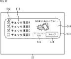
- FIG. 511 an example of the check item screen displayed on the display unit 57 in step S512 is shown in FIG.
- a check column display area 512 On the check item screen 511, a check column display area 512, a check item display area 513, an operation example display area 514, a button 515, and a button 516 are displayed.
- a plurality of check items are displayed in the check item display area 513, and a check column is provided in the check column display area 512 for each item. In addition, a check is added to the check column of the checked item.
- the check item display area 513 displays four items, “check item A”, “check item B”, “check item C”, and “check item D”.
- a check column is displayed for each item, and four check columns are displayed in the check column display section 512.
- the check column corresponding to these items is displayed in a checked state.
- Each of the check items A to D corresponds to, for example, an item (accuracy measured when calculating the reliability) checked as an abnormality of the sensor 51 as described with reference to FIG. .
- the check item A is an item for determining whether or not the jitter of the time stamp is within an allowable range
- the check item B is an item for determining whether or not the calibration of the geomagnetic sensor is sufficient.
- the check item C is an item for determining whether or not there is an offset variation
- the check item D is an item for determining whether or not the measurement range is sufficient. it can.
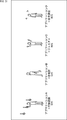
- an action to be performed by the user corresponding to the check item is displayed in text or a picture.
- an operation for checking an unchecked “check item D” is displayed in the operation example display area 514.
- a message “Please move as instructed” and a picture indicating that an operation of shaking the terminal 12 is performed are displayed.
- the button 515 displays the word “application activation”. This button 515 is an active state when all the check items are checked, and is an inactive state when there is an unchecked item. When this button is activated after being activated, the application is activated.
- the button 516 displays the word “skip”.
- This button 516 is a button that is operated when a check for accuracy evaluation is not performed (skip). When this button 516 is operated, the check for accuracy evaluation is interrupted and the application is activated.
- a message such as “Application accuracy is not guaranteed” may be displayed when the skip button 516 is operated, or below the button 516.
- Such a check item screen 511 is displayed on the display unit 57 in step S512.
- step S513 an action example corresponding to the item to be checked at that time is displayed in the action example display area 514.
- an operation model corresponding to “check item D” is displayed in the operation model display area 514.
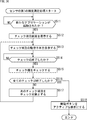
- step S5114 Check is performed when the user looks at the model displayed in the operation model display area 514 and performs a predetermined operation. In step S514, it is determined whether the check is finished. In step S514, the check state of the item to be checked is maintained until it is determined that the check has been completed.
- step S514 If it is determined in step S514 that the check has been completed, the process proceeds to step S515.
- step S515 a check is made in the check column corresponding to the check item determined to have been checked. For example, when it is determined that the check corresponding to “check item D” is completed, a check is displayed in the check column displayed at check item D.
- step S5166 it is determined whether or not all the processes have been completed. For example, as shown in FIG. 37, when there are four check items, when the check of “check item D” is finished, it is determined in step S516 that all checks are finished. Further, for example, when the check of “check item C” is completed, in step S516, it is determined that all the checks are not completed.
- step S516 If it is determined in step S516 that all checks have not been completed yet, the process proceeds to step S517, and the process from step S513 is repeated with the next item as a check item.
- step S516 determines whether all checks have been completed. If it is determined in step S516 that all checks have been completed, the process proceeds to step S518. In step S518, the start button is activated. That is, the button 515 that has been inactive is made active.
- the application When the user operates the activated button 515, the application is activated. When the check is completed, if it is determined that the accuracy of the sensor 51 cannot guarantee the accuracy of the application, a message notifying the user of this may be displayed. In such a case, the button 515 may be activated after the message is confirmed.
- the check result may be presented to the user. For example, a message such as “You can expect sufficient accuracy of the application on this terminal”, “There is a possibility that the accuracy of the application may be low on this terminal”, or a numerical value such as “Comfort level 80%” Display may be made to indicate the comfort of the user.
- step S551 it is determined whether or not a new application has been activated. This determination process can be performed in the same manner as step S511 of the flowchart shown in FIG.
- step S552 the achievement item screen is displayed on the display unit 57.
- an example of the achievement item screen displayed on the display unit 57 in step S552 is shown in FIG.
- a check column display area 552 an achievement item display area 553, a button 554, and a button 555 are displayed.
- a plurality of achievement items are displayed in the achievement item display area 553, and a check column is provided in the check column display area 552 for each item. In addition, a check is put in the check column of the completed item.
- the achievement item display area 553 displays four items, “achievement item A”, “achievement item B”, “achievement item C”, and “achievement item D”.
- a check column is displayed for each item, and four check columns are displayed in the check column display section 552.
- the check column corresponding to these items is displayed with a check.
- each of the achievement items A to D corresponds to, for example, an item (accuracy measured when calculating the reliability) achieved as an abnormality of the sensor 51 as described with reference to FIG.
- the items are items for measuring a predetermined accuracy.
- the button 554 displays the word “application activation”. This button 554 is activated when all the achievement items are achieved, and is inactive when there is an unachieved item. When this button is activated after being activated, the application is activated.
- the button 555 displays the word “skip”.
- This button 555 is a button that is operated when the achievement for accuracy evaluation is not performed (skip). When this button 555 is operated, the processing for accuracy measurement is interrupted and the application is activated.
- a message such as “Application accuracy is not guaranteed” may be displayed when the skip button 555 is operated, or below the button 555.
- step S553 Such an achievement item screen 551 is displayed on the display unit 57 in step S552, and the processes in and after step S553 are executed. That is, in step S553, it is determined whether or not the check that is the processing target has been completed (achieved). In this case, the checks corresponding to the achievement items A to D are checked sequentially or in parallel.
- step S513 when it is determined that the check of the achievement item that is the processing target is completed, the process proceeds to step S514.
- step S514 a check box corresponding to the achievement item determined to have been achieved is checked.
- step S515 it is determined whether or not all processing has been completed (whether all achievement items have been achieved). If it is determined in step S515 that the checks corresponding to all the achievement items have not yet been completed, the process proceeds to step S516, and the processes after step S553 are repeated using the next item as a check item.
- step S515 if it is determined in step S515 that all the achievement items have been checked, the process proceeds to step S517.
- step S517 the start button is activated. That is, the button 554 that has been inactive is made active.
- the application When the user operates the activated button 554, the application is activated. When the check is completed, if it is determined that the accuracy of the sensor 51 cannot guarantee the accuracy of the application, a message notifying the user of this may be displayed. In such a case, the button 554 may be configured to be active after the message is confirmed.
- the achievement result may be presented to the user. For example, a message such as “You can expect sufficient accuracy of the application on this terminal”, “There is a possibility that the accuracy of the application may be low on this terminal”, or a numerical value such as “Comfort level 80%” Display may be made to indicate the comfort of the user.
- FIG. 39 shows an example in which the word “application activation” is displayed on the button 554.
- the achievement level of the check item for example, “80%” is displayed, and the numerical value depends on the progress.
- the button may change. Then, for example, when it reaches 100%, the display may be switched to the wording “application activation” to be in an active state.
- the achievement item screen 551 shown in FIG. 39 shows a case where there is no area corresponding to the action example display area 514 displayed on the check item screen 511 shown in FIG.
- An area corresponding to the area 514 may be provided on the achievement item screen 551. For example, a picture or message that matches the checked item may be displayed.
- the first accuracy measurement processing of the sensor described with reference to FIGS. 36 and 37 and the second accuracy measurement processing of the sensor described with reference to FIGS. 38 and 39 may be combined.
- the check items that require the user's action are divided into the check items that do not require the user's action, and the check items that require the user's action are described with reference to FIGS.
- the second accuracy measurement process of the sensor described with reference to FIGS. 38 and 39 is applied. Also good.
- the second accuracy measurement process is applied and checked.
- the first accuracy measurement process Is applied and a check is made.
- the user knows whether or not the purchased application operates with sufficient accuracy on his / her terminal 12 before purchasing the application. If it is determined that the terminal 12 does not have sufficient accuracy, it can be determined not to purchase.
- the application does not operate with sufficient accuracy after purchase, the user may have a problem with the application and reduce the reliability of the application. It becomes possible to prevent.
- Such accuracy measurement is performed, for example, when a message (button) such as “Do you want to diagnose sensor data?” Described with reference to FIG. 21 is presented to the user and the user operates such a button. Also executed.
- a message such as “Do you want to diagnose sensor data?” Described with reference to FIG. 21 is presented to the user and the user operates such a button. Also executed.
- the sensor accuracy measurement process is executed, and the accuracy (reliability) of the sensor 51 is given to the user.
- the accuracy of the sensor 51 is measured, and the measurement result is presented to the user as necessary.
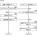
- step S601 the terminal 12 connects to the store server 11 via the network 13 (FIG. 1).
- the store server 11 accepts access from the terminal 12 in step S651, and requests the terminal 12 to send the accuracy of the sensor 51 in step S652.
- step S602 the terminal 12 accepts an accuracy request from the store server 11.
- step S603 the terminal 12 performs accuracy measurement. This accuracy measurement is performed by the above-described first accuracy measurement or second accuracy measurement (or measurement combining the first and second accuracy measurements).
- the measurement result is stored, and the process of reading the stored measurement result is executed in step S603. Also good.
- step S604 the measurement result is transmitted from the terminal 12 to the store server 11.
- step S653 the store server 11 receives the measurement result transmitted from the terminal 12 side.
- step S654 the store server 11 selects an application to be recommended. For example, in the store server 11, a plurality of applications that execute processing using data from sensors are targeted for sale.
- the accuracy of the sensor capable of sufficiently maintaining the accuracy is set, and the accuracy of the set sensor (set accuracy) and the measurement result (sensor) transmitted from the terminal 12 side are set. And the measurement accuracy are compared. As a result of the comparison, when the measurement accuracy is equal to or higher than the set accuracy, the application is selected as a recommended application.
- step S655 the selected application is presented to the user. That is, an application that will operate comfortably on the user's terminal 12 is recommended to the user.
- FIG. 41 shows a screen example of the recommended application displayed on the display unit 57 of the terminal 12.
- the display example shown in FIG. 41 is a screen displayed on the display unit 57 of the terminal 12 based on the data provided from the store server 11 side, and a plurality of applications are displayed in the application list display area 611. An example is shown.
- the application list display area 611 pictures and names representing applications selected as recommended on the store server 11 side are displayed. The user can select and purchase a desired application from the applications displayed in the application list display area 611.
- the application displayed in the application list display area 611 is an application that has been determined to be sufficiently accurate with the accuracy of the sensor 51 of the terminal 12, so that the user can purchase with confidence.
- the display example shown in FIG. 42 shows an example in which an accuracy display area 612 for displaying a numerical value indicating the accuracy of the sensor 51 when the application is executed is added to the display example shown in FIG.
- an accuracy display area 612 for displaying a numerical value indicating the accuracy of the sensor 51 when the application is executed is added to the display example shown in FIG.
- a plurality of applications are displayed in the application list display area 611, and the accuracy for each application is displayed in the accuracy display area 612.
- the application list display area 611 pictures and names representing applications selected as recommended on the store server 11 side are displayed, and how accurately these applications operate on the terminal 12. Are displayed in the accuracy display area 612. The user can select and purchase a desired application from the applications displayed in the application list display area 611, and can select the application with reference to accuracy.
- the application displayed in the application list display area 611 is an application that has been determined that sufficient accuracy can be ensured with the accuracy of the sensor 51 of the terminal 12, and the level of accuracy that can be obtained is also displayed. Therefore, the user can purchase with confidence.
- FIG. 43 shows another screen example of the recommended application displayed on the display unit 57 of the terminal 12.
- the display example shown in FIG. 43 shows an example in which a benchmark display area 613 for displaying the accuracy of the terminal 12 as a benchmark is added to the display example shown in FIG.
- a plurality of applications are displayed in the application list display area 611, and the benchmark of the terminal 12 is displayed in the benchmark display area 613.
- the application list display area 611 pictures and names representing applications selected as recommended on the store server 11 side are displayed.
- the benchmark display area 613 the result of accuracy measurement executed by the terminal 12 is displayed.
- the result of the accuracy measurement is represented by a numerical value as a benchmark score, and the numerical value is further represented by a line length.
- a gauge that can recognize at a glance whether or not the application operates comfortably at the position where the tip of the line is located is also displayed.
- the benchmark displayed in the benchmark display area 613 may be displayed as a benchmark corresponding to a plurality of applications in common, or may be displayed as a benchmark for each application.
- a benchmark corresponding to the selected application among the applications displayed in the application list display area 611 may be displayed.
- the numerical value and the line length displayed in the benchmark display area 613 are changed, or the numerical value and the line length are not changed. The display is changed.
- the user can select and purchase a desired application from the applications displayed in the application list display area 611, and can select the application with reference to the benchmark.
- the applications displayed in the application list display area 611 are applications that have been determined to be sufficiently accurate with the accuracy of the sensor 51 of the terminal 12, and refer to the benchmark for how much accuracy can be achieved. Therefore, the user can purchase with confidence.
- the database stores data for identifying terminals with good sensor accuracy. For example, when the above-described accuracy measurement is performed on the terminal 12 side, the measurement result is supplied from the terminal 12 side to the store server 11 side, and the supplied measurement result is accumulated, The accuracy of the sensor 51 of the terminal 12 may be collected for each terminal.
- the store server 11 periodically collects the number of times it is determined that an abnormality has occurred in the sensor 51, the accuracy measurement result, and the like.
- the accuracy of the sensor 51 of the terminal 12 may be collected for each terminal (for each type of terminal).
- the application creation side may measure the accuracy of the sensor 51 of the terminal 12 for each terminal 12 and store it in the database.
- application recommendation may be performed using a database in which the accuracy of the sensor 51 of the terminal 12 is accumulated.
- the second recommendation process of the application will be described with reference to the flowchart shown in FIG.
- step S701 the terminal 12 connects to the store server 11 via the network 13 (FIG. 1).
- the store server 11 accepts access from the terminal 12 in step S751, and requests the terminal 12 to send information for identifying the terminal 12 (terminal identification information) in step S752.
- the terminal identification information may be information for individually identifying the terminal 12, but is a terminal that may have the same sensor 51 accuracy, such as the model name (model version) of the terminal 12. It may be information that can be determined whether or not.
- step S ⁇ b> 702 the terminal 12 receives a request for sending terminal identification information from the store server 11.
- step S703 the terminal 12 reads the terminal identification information and sends it to the store server 11 side.
- step S753 the store server 11 receives the terminal identification information transmitted from the terminal 12 side.
- step S754 the store server 11 refers to the database and selects a recommended application. As described above, data for discriminating terminals with high sensor accuracy is accumulated in the database.
- the store server 11 refers to the database and the terminal identification information, and determines whether the terminal 12 that has transmitted the terminal identification information is a terminal with good sensor accuracy. When it is determined that the terminal 12 that has transmitted the terminal identification information is a terminal with good sensor accuracy, an application that operates comfortably on the terminal with high sensor accuracy is selected. On the other hand, if it is determined that the terminal 12 that has transmitted the terminal identification information is not a terminal with good sensor accuracy, an application that operates with the sensor accuracy is selected.
- step S755 the selected application is recommended. This recommendation is performed by displaying the screen shown in FIG. 41, FIG. 42, or FIG. 43 on the display unit 57 of the terminal 12 as in the case described in step S ⁇ b> 655 of the flowchart shown in FIG. 40.
- the application may be selected and recommended by referring to the database according to the accuracy of the terminal 12 (sensor 51).
- the user can select and purchase a desired application from the applications displayed in the application list display area 611.
- the present technology it is possible to measure the accuracy of the sensor 51 (calculate reliability). In addition, when the accuracy of the sensor 51 is lowered, which affects the processing result of an application that performs processing using the output from the sensor 51, the user can be made aware of this.
- FIG. 45 is a block diagram for explaining the hardware configuration of the information processing apparatus.
- the information processing apparatus 900 includes a CPU 901, a ROM 903, and a RAM 905. Further, the information processing apparatus 900 may include a host bus 907, a bridge 909, an external bus 911, an interface 913, an input device 915, an output device 917, a storage device 919, a drive 921, a connection port 923, and a communication device 925.
- the CPU 901 functions as an arithmetic processing device and a control device, and controls all or a part of the operation in the information processing device 900 according to various programs recorded in the ROM 903, the RAM 905, the storage device 919, or the removable recording medium 927.
- the ROM 903 stores programs and calculation parameters used by the CPU 901.
- the RAM 905 primarily stores programs used in the execution of the CPU 901, parameters that change as appropriate during the execution, and the like.
- the CPU 901, the ROM 903, and the RAM 905 are connected to each other by a host bus 907 configured by an internal bus such as a CPU bus. Further, the host bus 907 is connected via a bridge 909 to an external bus 911 such as a PCI (Peripheral-Component-Interconnect / Interface) bus.
- PCI Peripheral-Component-Interconnect / Interface
- the input device 915 is a device operated by the user, such as a mouse, a keyboard, a touch panel, a button, a switch, and a lever.
- the input device 915 may be, for example, a remote control device that uses infrared rays or other radio waves, or may be an external connection device 929 such as a mobile phone that supports the operation of the information processing device 900.
- the input device 915 includes an input control circuit that generates an input signal based on information input by the user and outputs the input signal to the CPU 901. The user operates the input device 915 to input various data and instruct processing operations to the information processing device 900.
- the output device 917 is a device that can notify the user of the acquired information visually or audibly.
- the output device 917 can be, for example, a display device such as an LCD (Liquid Crystal Display), a PDP (Plasma Display Panel), an organic EL (Electro-Luminescence) display, an audio output device such as a speaker and headphones, and a printer device.
- the output device 917 outputs the result obtained by the processing of the information processing device 900 as video such as text or an image, or outputs it as audio such as voice or sound.
- the storage device 919 is a data storage device configured as an example of a storage unit of the information processing device 900.
- the storage device 919 includes, for example, a magnetic storage device such as an HDD (Hard Disk Drive), a semiconductor storage device, an optical storage device, or a magneto-optical storage device.
- the storage device 919 stores programs executed by the CPU 901, various data, various data acquired from the outside, and the like.
- the drive 921 is a reader / writer for a removable recording medium 927 such as a magnetic disk, an optical disk, a magneto-optical disk, or a semiconductor memory, and is built in or externally attached to the information processing apparatus 900.
- the drive 921 reads information recorded on the attached removable recording medium 927 and outputs the information to the RAM 905.
- the drive 921 writes a record in the attached removable recording medium 927.
- the connection port 923 is a port for directly connecting a device to the information processing apparatus 900.
- the connection port 923 can be, for example, a USB (Universal Serial Bus) port, an IEEE 1394 port, a SCSI (Small Computer System Interface) port, or the like. Further, the connection port 923 may be an RS-232C port, an optical audio terminal, an HDMI (registered trademark) (High-Definition Multimedia Interface) port, or the like.
- the communication device 925 is a communication interface configured with, for example, a communication device for connecting to the communication network 931.
- the communication device 925 can be, for example, a communication card for wired or wireless LAN (Local Area Network), Bluetooth (registered trademark), or WUSB (Wireless USB).
- the communication device 925 may be a router for optical communication, a router for ADSL (Asymmetric Digital Subscriber Line), or a modem for various communication.
- the communication device 925 transmits and receives signals and the like using a predetermined protocol such as TCP / IP with the Internet and other communication devices, for example.
- the communication network 931 connected to the communication device 925 is a wired or wireless network, such as the Internet, a home LAN, infrared communication, radio wave communication, or satellite communication.
- Each component described above may be configured using a general-purpose member, or may be configured by hardware specialized for the function of each component. Such a configuration can be appropriately changed according to the technical level at the time of implementation.
- the program executed by the computer may be a program that is processed in time series in the order described in this specification, or in parallel or at a necessary timing such as when a call is made. It may be a program for processing.
- system represents the entire apparatus composed of a plurality of apparatuses.
- this technique can also take the following structures.
- a sensor A processing unit that performs processing using data from the sensor; A determination unit for determining whether or not the accuracy of the sensor is reduced;
- An information processing apparatus comprising: a notification unit that notifies a user that the accuracy of the sensor has decreased when it is determined that the accuracy of the sensor has decreased.
- the information processing apparatus according to (1) wherein the processing unit executes processing by a predetermined application.
- the application is an application that recognizes the user's behavior, The information processing apparatus according to (2), wherein the determination unit determines whether or not the accuracy of the result of the action recognition by the application is reduced due to the accuracy of the sensor.
- the information processing apparatus uses the processing result of the processing unit, which may have low accuracy, as the processing result.
- the information processing apparatus wherein the information is displayed with a mark, the processing result is displayed lighter than other processing results, or displayed in a color different from the other processing results.
- the notification unit displays a message that causes the user to recognize the cause of the decrease in accuracy of the sensor, together with a processing result that may be low in accuracy,
- the information processing apparatus according to (10) or (11) .
- the notification unit displays a message that allows the user to recognize a countermeasure against the decrease in accuracy of the sensor, together with a processing result that may be low in accuracy, in any one of (10) to (12)
- the notification unit displays a picture that allows the user to recognize that the accuracy of the sensor is reduced, together with a processing result that may be low in accuracy, according to any one of (10) to (13). Information processing device.
- the notification unit displays the continuous processing result as a display in which the color gradually changes. Any of (10) to (14) An information processing apparatus according to claim 1.
- the information processing apparatus according to (2) wherein the determination by the determination unit is performed for each application.
- 17.) The information processing apparatus according to (16), wherein a determination result by the determination unit performed for each application is presented to a user.
- an information processing method of an information processing apparatus including a sensor Perform processing using data from the sensor, Determine whether the accuracy of the sensor is reduced, An information processing method including a step of notifying a user that the accuracy of the sensor is reduced when it is determined that the accuracy of the sensor is reduced.
- a computer that controls an information processing apparatus including a sensor Perform processing using data from the sensor, Determine whether the accuracy of the sensor is reduced, A program for executing a process including a step of notifying a user that the accuracy of the sensor is lowered when it is determined that the accuracy of the sensor is lowered.
- 11 store servers, 12 terminals, 51 sensors, 52 checkers, 53 recognition units, 54 determination units, 55 storage units, 56 display control units, 57 display units
Abstract
Description
図1は、本技術を適用した端末を含むシステムの一実施の形態の構成を示す図である。図1に示したシステムは、ストアサーバ11、端末12、ネットワーク13を含む構成とされている。 <System configuration>
FIG. 1 is a diagram illustrating a configuration of an embodiment of a system including a terminal to which the present technology is applied. The system shown in FIG. 1 includes a
図2は、端末12の構成(機能)について説明するための図である。端末12は、上記したように、所定のアプリケーションをストアサーバ11からダウンロードし、ダウンロードした所定のアプリケーションに基づく処理を実行する。なおここでは、ストアサーバ11からダウンロードされ、端末12側で処理が実行されるとして説明を続けるが、クラウドシステムなどを適用することもでき、本技術は、クラウドシステムなどを適用した場合においても適用できる。 <Terminal configuration>
FIG. 2 is a diagram for explaining the configuration (function) of the terminal 12. As described above, the terminal 12 downloads a predetermined application from the
まず、図4に示したフローチャートを参照し、図1に示したシステムの動作について説明する。 <System operation>
First, the operation of the system shown in FIG. 1 will be described with reference to the flowchart shown in FIG.
図5に示したフローチャートを参照し、センサ51の信頼度をユーザに提示するための処理(センサの信頼度の第1の表示処理)について説明する。 <First display process of sensor reliability>
A process for presenting the reliability of the
ユーザの指示があったときに信頼度が表示されるようにした場合について、図9に示したフローチャートを参照して説明する。 <Second display process of sensor reliability>
A case where the reliability is displayed when the user gives an instruction will be described with reference to the flowchart shown in FIG.
信頼度が所定の値以下になったときに、ユーザにそのことを知らせるために信頼度が表示されるようにしても良い。信頼度が所定の値以下になった場合に、ユーザにそのことを知らせることで、ユーザの判断により、何らかの処理、例えば、起動されているアプリケーションを停止させるといったような処理をユーザに実行させることができる。 <Third display process of sensor reliability>
When the reliability falls below a predetermined value, the reliability may be displayed to notify the user of that fact. When the reliability falls below a predetermined value, by notifying the user of that fact, the user is allowed to execute some processing, for example, processing such as stopping the activated application, at the user's discretion. Can do.
端末12(アプリケーションA)は、ユーザの行動認識を行い、認識結果を記憶部55や表示制御部56に供給している。この認識結果ととともに、上記したセンサ51の信頼度をユーザに提供する場合について説明を加える。 <Fourth display process of sensor reliability>
The terminal 12 (application A) recognizes the user's behavior and supplies the recognition result to the
ユーザの指示があったときに信頼度が表示されるようにした場合について、図22のフローチャートを参照して説明する。 <Fifth display process of sensor reliability>
A case where the reliability is displayed when the user gives an instruction will be described with reference to the flowchart of FIG.
上述してきたように、センサ51の信頼度とアプリケーションAによるユーザの行動の認識結果は、関連付けられて、記憶部55に記憶されている。この記憶部55に記憶されている信頼度と認識結果(ログ)を読み出し、ユーザに提示することも可能である。 <Sixth display process of sensor reliability>
As described above, the reliability of the
記憶部55からログを読み出し、信頼度や認識結果を表示する際の、他の表示例について、図28に示したフローチャートを参照して説明する(センサの信頼度の第7の表示処理について説明する)。 <Seventh display process of sensor reliability>
Another display example when reading the log from the
上記したように、本技術によれば、センサ51(端末12)に異常が発生しているとき(精度が低下しているとき)には、そのことをユーザに通知することができる。このセンサ51に異常が発生しているか否かは、所定のアプリケーションが求めている精度にもよる。 <Determining reliability for each application>
As described above, according to the present technology, when an abnormality has occurred in the sensor 51 (terminal 12) (when the accuracy has decreased), this can be notified to the user. Whether or not an abnormality has occurred in the
上述したように、本技術によれば、センサ51(端末12)の精度(信頼度)が低下した場合に、そのことをユーザに提示することができる。提示するか否か(アラートを表示するか否か、アラート付きの表示をするか否か)は、信頼度が所定の閾値以下になったか否かを判定することで行われる。 <Reliability threshold setting>
As described above, according to the present technology, when the accuracy (reliability) of the sensor 51 (terminal 12) is lowered, this can be presented to the user. Whether to present (whether to display an alert or whether to display with an alert) is determined by determining whether the reliability is equal to or lower than a predetermined threshold.
上記したように、本技術によれば、センサ51(端末12)の精度を測定する(信頼度を算出する)ことができる。このことを利用し、例えば、ユーザが、ストアサーバ11からアプリケーションAを購入するとき、そのアプリケショーンAが、快適に動作するために必要な精度を、センサ51は有しているか否かを判定したり、その判定結果に基づき、ユーザに所定のアプリケーションを推薦したりすることができる。 <First accuracy measurement process of sensor>
As described above, according to the present technology, the accuracy of the sensor 51 (terminal 12) can be measured (reliability can be calculated). Using this, for example, when the user purchases the application A from the
上述したセンサの第1の精度測定処理においては、ユーザに測定のために必要な動作を行わせることで、チェックが行われたが、複数のチェックのうちの一部、または全てのチェックをユーザの手を煩わすことなく行われるようにしても良い。ここではユーザの手を煩わすことなくチェックが行われる場合を、センサの第2の精度測定処理として、図38に示すフローチャートを参照して説明する。 <Second accuracy measurement process of sensor>
In the first accuracy measurement process of the sensor described above, the check is performed by causing the user to perform an operation necessary for the measurement. However, some or all of the multiple checks are performed by the user. It may be performed without bothering the hands. Here, the case where the check is performed without bothering the user will be described as the second accuracy measurement processing of the sensor with reference to the flowchart shown in FIG.
このような精度測定の結果は、ストアサーバ11側で利用し、アプリケーションの推薦などの処理に用いられるようにすることも可能である。図40に示したフローチャートを参照し、アプリケーションの第1の推薦処理について説明する。 <First recommendation process of application>
The result of such accuracy measurement can be used on the
次に、アプリケーションの第2の推薦処理について説明する。第2の推薦処理においては、ストアサーバ11にデータベースを設け、そのデータベースが参照されて、推薦するアプリケーションが選択される。 <Second recommendation process of application>
Next, the second recommendation process of the application will be described. In the second recommendation process, a database is provided in the
図45を参照して、上記で説明された本開示の実施の形態におけるストアサーバ11、端末12を実現しうる情報処理装置900のハードウェア構成について説明する。 <Hardware configuration>
With reference to FIG. 45, a hardware configuration of the
(1)
センサと、
前記センサからのデータを用いた処理を行う処理部と、
前記センサの精度が低下しているか否かを判定する判定部と、
前記センサの精度が低下したと判定された場合、ユーザに前記センサの精度が低下していることを通知する通知部と
を備える情報処理装置。
(2)
前記処理部は、所定のアプリケーションによる処理を実行する
前記(1)に記載の情報処理装置。
(3)
前記アプリケーションは、前記ユーザの行動認識を行うアプリケーションであり、
前記判定部は、前記アプリケーションによる前記行動認識の結果の精度が、前記センサの精度により低下したか否かを判定する
前記(2)に記載の情報処理装置。
(4)
前記通知部は、前記センサの精度が低下していることを前記ユーザに認識させるメッセージを表示する
前記(1)乃至(3)のいずれかに記載の情報処理装置。
(5)
前記通知部は、前記センサの精度が低下している原因を前記ユーザに認識させるメッセージを表示する
前記(1)乃至(4)のいずれかに記載の情報処理装置。
(6)
前記通知部は、前記センサの精度が低下していることに対する対策を前記ユーザに認識させるメッセージを表示する
前記(1)乃至(5)のいずれかに記載の情報処理装置。
(7)
前記判定部は、前記センサの信頼度を算出する
前記(1)乃至(6)のいずれかに記載の情報処理装置。
(8)
前記信頼度は、数値、インジケータ、または時間経過による前記信頼度の変化を表すグラフで、前記ユーザに提示される
前記(7)に記載の情報処理装置。
(9)
前記通知部は、前記処理部による処理結果とともに、前記センサの精度が低下していることを通知する
前記(1)乃至(3)のいずれかに記載の情報処理装置。
(10)
前記通知部は、精度が低い可能性がある前記処理部による処理結果を、精度が低い可能性があることユーザに認識させるための表示を行う
前記(1)に記載の情報処理装置。
(11)
前記通知部は、精度が低い可能性がある前記処理部による処理結果を、前記処理結果に?マークを付けて表示する、前記処理結果を他の処理結果よりも薄く表示する、または他の処理結果とは異なる色で表示する
前記(10)に記載の情報処理装置。
(12)
前記通知部は、前記センサの精度が低下している原因を前記ユーザに認識させるメッセージを、精度が低い可能性がある処理結果とともに表示する
前記(10)または(11)に記載の情報処理装置。
(13)
前記通知部は、前記センサの精度が低下していることに対する対策を前記ユーザに認識させるメッセージを、精度が低い可能性がある処理結果とともに表示する
前記(10)乃至(12)のいずれかに記載の情報処理装置。
(14)
前記通知部は、前記センサの精度が低下していることを前記ユーザに認識させる絵を、精度が低い可能性がある処理結果とともに表示する
前記(10)乃至(13)のいずれかに記載の情報処理装置。
(15)
前記通知部は、精度が低い可能性がある処理結果が連続している場合、連続している前記処理結果の表示を、徐々に色が変わる表示とする
前記(10)乃至(14)のいずれかに記載の情報処理装置。
(16)
前記判定部による判定は、前記アプリケーション毎に行う
前記(2)に記載の情報処理装置。
(17)
前記アプリケーション毎に行われた前記判定部による判定結果をユーザに提示する
前記(16)に記載の情報処理装置。
(18)
センサを備える情報処理装置の情報処理方法において、
前記センサからのデータを用いた処理を行い、
前記センサの精度が低下しているか否かを判定し、
前記センサの精度が低下したと判定された場合、ユーザに前記センサの精度が低下していることを通知する
ステップを含む情報処理方法。
(19)
センサを備える情報処理装置を制御するコンピュータに、
前記センサからのデータを用いた処理を行い、
前記センサの精度が低下しているか否かを判定し、
前記センサの精度が低下したと判定された場合、ユーザに前記センサの精度が低下していることを通知する
ステップを含む処理を実行させるためのプログラム。 In addition, this technique can also take the following structures.
(1)
A sensor,
A processing unit that performs processing using data from the sensor;
A determination unit for determining whether or not the accuracy of the sensor is reduced;
An information processing apparatus comprising: a notification unit that notifies a user that the accuracy of the sensor has decreased when it is determined that the accuracy of the sensor has decreased.
(2)
The information processing apparatus according to (1), wherein the processing unit executes processing by a predetermined application.
(3)
The application is an application that recognizes the user's behavior,
The information processing apparatus according to (2), wherein the determination unit determines whether or not the accuracy of the result of the action recognition by the application is reduced due to the accuracy of the sensor.
(4)
The information processing apparatus according to any one of (1) to (3), wherein the notification unit displays a message that allows the user to recognize that the accuracy of the sensor is decreasing.
(5)
The information processing apparatus according to any one of (1) to (4), wherein the notification unit displays a message that causes the user to recognize a cause of a decrease in accuracy of the sensor.
(6)
The information processing apparatus according to any one of (1) to (5), wherein the notification unit displays a message that allows the user to recognize a countermeasure against a decrease in accuracy of the sensor.
(7)
The information processing apparatus according to any one of (1) to (6), wherein the determination unit calculates a reliability of the sensor.
(8)
The information processing apparatus according to (7), wherein the reliability is a numerical value, an indicator, or a graph that represents a change in the reliability over time, and is presented to the user.
(9)
The information processing apparatus according to any one of (1) to (3), wherein the notification unit notifies that the accuracy of the sensor is reduced along with a processing result by the processing unit.
(10)
The information processing apparatus according to (1), wherein the notification unit performs display for causing a user to recognize that the processing result by the processing unit that may have low accuracy may be low in accuracy.
(11)
The notification unit uses the processing result of the processing unit, which may have low accuracy, as the processing result. The information processing apparatus according to (10), wherein the information is displayed with a mark, the processing result is displayed lighter than other processing results, or displayed in a color different from the other processing results.
(12)
The notification unit displays a message that causes the user to recognize the cause of the decrease in accuracy of the sensor, together with a processing result that may be low in accuracy, The information processing apparatus according to (10) or (11) .
(13)
The notification unit displays a message that allows the user to recognize a countermeasure against the decrease in accuracy of the sensor, together with a processing result that may be low in accuracy, in any one of (10) to (12) The information processing apparatus described.
(14)
The notification unit displays a picture that allows the user to recognize that the accuracy of the sensor is reduced, together with a processing result that may be low in accuracy, according to any one of (10) to (13). Information processing device.
(15)
When the processing result that may have low accuracy is continuous, the notification unit displays the continuous processing result as a display in which the color gradually changes. Any of (10) to (14) An information processing apparatus according to claim 1.
(16)
The information processing apparatus according to (2), wherein the determination by the determination unit is performed for each application.
(17)
The information processing apparatus according to (16), wherein a determination result by the determination unit performed for each application is presented to a user.
(18)
In an information processing method of an information processing apparatus including a sensor,
Perform processing using data from the sensor,
Determine whether the accuracy of the sensor is reduced,
An information processing method including a step of notifying a user that the accuracy of the sensor is reduced when it is determined that the accuracy of the sensor is reduced.
(19)
In a computer that controls an information processing apparatus including a sensor,
Perform processing using data from the sensor,
Determine whether the accuracy of the sensor is reduced,
A program for executing a process including a step of notifying a user that the accuracy of the sensor is lowered when it is determined that the accuracy of the sensor is lowered.
Claims (19)
- センサと、
前記センサからのデータを用いた処理を行う処理部と、
前記センサの精度が低下しているか否かを判定する判定部と、
前記センサの精度が低下したと判定された場合、ユーザに前記センサの精度が低下していることを通知する通知部と
を備える情報処理装置。 A sensor,
A processing unit that performs processing using data from the sensor;
A determination unit for determining whether or not the accuracy of the sensor is reduced;
An information processing apparatus comprising: a notification unit that notifies a user that the accuracy of the sensor has decreased when it is determined that the accuracy of the sensor has decreased. - 前記処理部は、所定のアプリケーションによる処理を実行する
請求項1に記載の情報処理装置。 The information processing apparatus according to claim 1, wherein the processing unit executes processing by a predetermined application. - 前記アプリケーションは、前記ユーザの行動認識を行うアプリケーションであり、
前記判定部は、前記アプリケーションによる前記行動認識の結果の精度が、前記センサの精度により低下したか否かを判定する
請求項2に記載の情報処理装置。 The application is an application that recognizes the user's behavior,
The information processing apparatus according to claim 2, wherein the determination unit determines whether or not the accuracy of the result of the action recognition by the application is reduced due to the accuracy of the sensor. - 前記通知部は、前記センサの精度が低下していることを前記ユーザに認識させるメッセージを表示する
請求項1に記載の情報処理装置。 The information processing apparatus according to claim 1, wherein the notification unit displays a message that allows the user to recognize that the accuracy of the sensor is reduced. - 前記通知部は、前記センサの精度が低下している原因を前記ユーザに認識させるメッセージを表示する
請求項1に記載の情報処理装置。 The information processing apparatus according to claim 1, wherein the notification unit displays a message that causes the user to recognize a cause of a decrease in accuracy of the sensor. - 前記通知部は、前記センサの精度が低下していることに対する対策を前記ユーザに認識させるメッセージを表示する
請求項1に記載の情報処理装置。 The information processing apparatus according to claim 1, wherein the notification unit displays a message that allows the user to recognize a countermeasure against a decrease in accuracy of the sensor. - 前記判定部は、前記センサの信頼度を算出する
請求項1に記載の情報処理装置。 The information processing apparatus according to claim 1, wherein the determination unit calculates the reliability of the sensor. - 前記信頼度は、数値、インジケータ、または時間経過による前記信頼度の変化を表すグラフで、前記ユーザに提示される
請求項7に記載の情報処理装置。 The information processing apparatus according to claim 7, wherein the reliability is a numerical value, an indicator, or a graph representing a change in the reliability over time, and is presented to the user. - 前記通知部は、前記処理部による処理結果とともに、前記センサの精度が低下していることを通知する
請求項1に記載の情報処理装置。 The information processing apparatus according to claim 1, wherein the notification unit notifies that the accuracy of the sensor is lowered together with a processing result by the processing unit. - 前記通知部は、精度が低い可能性がある前記処理部による処理結果を、精度が低い可能性があることユーザに認識させるための表示を行う
請求項1に記載の情報処理装置。 The information processing apparatus according to claim 1, wherein the notification unit performs display for causing a user to recognize that the processing result by the processing unit that may have low accuracy may be low in accuracy. - 前記通知部は、精度が低い可能性がある前記処理部による処理結果を、前記処理結果に?マークを付けて表示する、前記処理結果を他の処理結果よりも薄く表示する、または他の処理結果とは異なる色で表示する
請求項1に記載の情報処理装置。 The notification unit uses the processing result of the processing unit, which may have low accuracy, as the processing result. The information processing apparatus according to claim 1, wherein the information is displayed with a mark, the processing result is displayed lighter than other processing results, or displayed in a color different from the other processing results. - 前記通知部は、前記センサの精度が低下している原因を前記ユーザに認識させるメッセージを、精度が低い可能性がある処理結果とともに表示する
請求項10に記載の情報処理装置。 The information processing apparatus according to claim 10, wherein the notification unit displays a message that causes the user to recognize the cause of a decrease in accuracy of the sensor, together with a processing result that may be low in accuracy. - 前記通知部は、前記センサの精度が低下していることに対する対策を前記ユーザに認識させるメッセージを、精度が低い可能性がある処理結果とともに表示する
請求項10に記載の情報処理装置。 The information processing apparatus according to claim 10, wherein the notification unit displays a message that causes the user to recognize a countermeasure against a decrease in accuracy of the sensor, together with a processing result that may have a low accuracy. - 前記通知部は、前記センサの精度が低下していることを前記ユーザに認識させる絵を、精度が低い可能性がある処理結果とともに表示する
請求項10に記載の情報処理装置。 The information processing apparatus according to claim 10, wherein the notification unit displays a picture that allows the user to recognize that the accuracy of the sensor is reduced, together with a processing result that may be low in accuracy. - 前記通知部は、精度が低い可能性がある処理結果が連続している場合、連続している前記処理結果の表示を、徐々に色が変わる表示とする
請求項10に記載の情報処理装置。 The information processing apparatus according to claim 10, wherein when the processing result that may have low accuracy is continuous, the notification unit displays the continuous processing result as a display that gradually changes in color. - 前記判定部による判定は、前記アプリケーション毎に行う
請求項2に記載の情報処理装置。 The information processing apparatus according to claim 2, wherein the determination by the determination unit is performed for each application. - 前記アプリケーション毎に行われた前記判定部による判定結果をユーザに提示する
請求項16に記載の情報処理装置。 The information processing apparatus according to claim 16, wherein a determination result by the determination unit performed for each application is presented to a user. - センサを備える情報処理装置の情報処理方法において、
前記センサからのデータを用いた処理を行い、
前記センサの精度が低下しているか否かを判定し、
前記センサの精度が低下したと判定された場合、ユーザに前記センサの精度が低下していることを通知する
ステップを含む情報処理方法。 In an information processing method of an information processing apparatus including a sensor,
Perform processing using data from the sensor,
Determine whether the accuracy of the sensor is reduced,
An information processing method including a step of notifying a user that the accuracy of the sensor is reduced when it is determined that the accuracy of the sensor is reduced. - センサを備える情報処理装置を制御するコンピュータに、
前記センサからのデータを用いた処理を行い、
前記センサの精度が低下しているか否かを判定し、
前記センサの精度が低下したと判定された場合、ユーザに前記センサの精度が低下していることを通知する
ステップを含む処理を実行させるためのプログラム。 In a computer that controls an information processing apparatus including a sensor,
Perform processing using data from the sensor,
Determine whether the accuracy of the sensor is reduced,
A program for executing a process including a step of notifying a user that the accuracy of the sensor is lowered when it is determined that the accuracy of the sensor is lowered.
Priority Applications (3)
| Application Number | Priority Date | Filing Date | Title |
|---|---|---|---|
| EP17741200.4A EP3407028B1 (en) | 2016-01-19 | 2017-01-05 | Information processing device, information processing method, and program |
| CN201780006597.2A CN108463692A (en) | 2016-01-19 | 2017-01-05 | Information processing equipment, information processing method and program |
| US15/772,194 US20180313676A1 (en) | 2016-01-19 | 2017-01-05 | Information processing apparatus, information processing method, and program |
Applications Claiming Priority (2)
| Application Number | Priority Date | Filing Date | Title |
|---|---|---|---|
| JP2016008153 | 2016-01-19 | ||
| JP2016-008153 | 2016-01-19 |
Publications (1)
| Publication Number | Publication Date |
|---|---|
| WO2017126320A1 true WO2017126320A1 (en) | 2017-07-27 |
Family
ID=59361698
Family Applications (1)
| Application Number | Title | Priority Date | Filing Date |
|---|---|---|---|
| PCT/JP2017/000073 WO2017126320A1 (en) | 2016-01-19 | 2017-01-05 | Information processing device, information processing method, and program |
Country Status (4)
| Country | Link |
|---|---|
| US (1) | US20180313676A1 (en) |
| EP (1) | EP3407028B1 (en) |
| CN (1) | CN108463692A (en) |
| WO (1) | WO2017126320A1 (en) |
Cited By (1)
| Publication number | Priority date | Publication date | Assignee | Title |
|---|---|---|---|---|
| WO2018123591A1 (en) * | 2016-12-26 | 2018-07-05 | 株式会社タニタ | Activity level calculation program, activity level calculation method, mobile terminal, and recording medium |
Families Citing this family (1)
| Publication number | Priority date | Publication date | Assignee | Title |
|---|---|---|---|---|
| JP7066590B2 (en) * | 2018-10-05 | 2022-05-13 | 本田技研工業株式会社 | Diagnostic equipment, diagnostic methods, and programs |
Citations (5)
| Publication number | Priority date | Publication date | Assignee | Title |
|---|---|---|---|---|
| JP2010086376A (en) * | 2008-10-01 | 2010-04-15 | Panasonic Corp | Sensor unit |
| JP2011215787A (en) * | 2010-03-31 | 2011-10-27 | Sogo Keibi Hosho Co Ltd | Person counter and accuracy evaluation method |
| JP2013003649A (en) | 2011-06-13 | 2013-01-07 | Sony Corp | Information processing device, information processing method, and computer program |
| JP2013188260A (en) * | 2012-03-12 | 2013-09-26 | Terumo Corp | Load measuring system and information processing apparatus |
| JP2016007503A (en) * | 2014-06-26 | 2016-01-18 | 京セラ株式会社 | Measurement apparatus, measurement method, and electronic apparatus with measurement apparatus |
Family Cites Families (8)
| Publication number | Priority date | Publication date | Assignee | Title |
|---|---|---|---|---|
| US6757641B1 (en) * | 2002-06-28 | 2004-06-29 | The United States Of America As Represented By The Administrator Of The National Aeronautics And Space Administration | Multi sensor transducer and weight factor |
| WO2009086456A1 (en) * | 2007-12-26 | 2009-07-09 | Nellcor Puritan Bennett Llc | Historical trend icons for physiological parameters |
| CN201319040Y (en) * | 2008-01-23 | 2009-09-30 | 美捷特(厦门)传感器件有限公司 | Status detecting device for IEPE piezoelectric acceleration sensor |
| US20100274528A1 (en) * | 2009-04-22 | 2010-10-28 | Rosemount Inc. | Field device with measurement accuracy reporting |
| CN102667090B (en) * | 2009-06-24 | 2015-03-04 | 康明斯知识产权公司 | Apparatus, system, and method for estimating deterioration of a NOX sensor response rate |
| KR101251836B1 (en) * | 2011-09-02 | 2013-04-09 | 현대자동차주식회사 | Driver condition detecting device with IR sensor |
| US9610013B2 (en) * | 2013-11-14 | 2017-04-04 | Dexcom, Inc. | Indicator and analytics for sensor insertion in a continuous analyte monitoring system and related methods |
| CN105100732B (en) * | 2015-08-26 | 2016-10-26 | 深圳市银之杰科技股份有限公司 | A kind of server in machine room long-distance monitoring method and system |
-
2017
- 2017-01-05 CN CN201780006597.2A patent/CN108463692A/en active Pending
- 2017-01-05 EP EP17741200.4A patent/EP3407028B1/en active Active
- 2017-01-05 WO PCT/JP2017/000073 patent/WO2017126320A1/en active Application Filing
- 2017-01-05 US US15/772,194 patent/US20180313676A1/en not_active Abandoned
Patent Citations (5)
| Publication number | Priority date | Publication date | Assignee | Title |
|---|---|---|---|---|
| JP2010086376A (en) * | 2008-10-01 | 2010-04-15 | Panasonic Corp | Sensor unit |
| JP2011215787A (en) * | 2010-03-31 | 2011-10-27 | Sogo Keibi Hosho Co Ltd | Person counter and accuracy evaluation method |
| JP2013003649A (en) | 2011-06-13 | 2013-01-07 | Sony Corp | Information processing device, information processing method, and computer program |
| JP2013188260A (en) * | 2012-03-12 | 2013-09-26 | Terumo Corp | Load measuring system and information processing apparatus |
| JP2016007503A (en) * | 2014-06-26 | 2016-01-18 | 京セラ株式会社 | Measurement apparatus, measurement method, and electronic apparatus with measurement apparatus |
Cited By (1)
| Publication number | Priority date | Publication date | Assignee | Title |
|---|---|---|---|---|
| WO2018123591A1 (en) * | 2016-12-26 | 2018-07-05 | 株式会社タニタ | Activity level calculation program, activity level calculation method, mobile terminal, and recording medium |
Also Published As
| Publication number | Publication date |
|---|---|
| EP3407028A1 (en) | 2018-11-28 |
| CN108463692A (en) | 2018-08-28 |
| EP3407028A4 (en) | 2019-01-23 |
| US20180313676A1 (en) | 2018-11-01 |
| EP3407028B1 (en) | 2020-09-02 |
Similar Documents
| Publication | Publication Date | Title |
|---|---|---|
| EP2821897B1 (en) | Finger detection on touch screens for mobile devices | |
| JP2015033425A (en) | Sensor unit and motion detector | |
| JP2006201866A (en) | Work instruction system | |
| JP6377950B2 (en) | Mobile device and information processing system | |
| CN111742540B (en) | Method, mobile device and computer readable medium for detecting patterns and behaviors to avoid mobile terminal drop events | |
| WO2020228307A1 (en) | Fall detection method and apparatus, and wearable device | |
| WO2017126320A1 (en) | Information processing device, information processing method, and program | |
| JP6213026B2 (en) | Fine reading judgment device, fine reading judgment method, and fine reading judgment program | |
| JP2008305339A (en) | Operation time measuring instrument and method, skill level determining device and method, and program | |
| JP2020507434A (en) | System and method for monitoring and measuring itch | |
| US10488981B2 (en) | System and method of measuring continuous touch controller latency | |
| JP6313872B2 (en) | Alcohol measurement system and alcohol measurement video storage program | |
| TWI597048B (en) | Physical activity meter and event information recording system | |
| JP6996379B2 (en) | Learning system and programs for learning system | |
| KR20180114396A (en) | Concentration measuring device using motion detection | |
| KR102644472B1 (en) | Apparatus and Method For Alarm of Body Temperature | |
| JP6940813B2 (en) | Step count device, step count method and program | |
| JP2011192063A (en) | Operating situation monitoring program, device and method | |
| KR102193653B1 (en) | Diagonis system for user behavior ad user cognition ability and method thereof | |
| JP6116409B2 (en) | Waveform display device, waveform display method, and waveform display program | |
| JP2015049859A (en) | Manipulation ability evaluation program and manipulation ability evaluation system | |
| JP2017198565A (en) | Detector, infrared sensor, detection method, and program | |
| JP6881319B2 (en) | Information processing equipment, information processing method and storage medium | |
| JP2010244293A (en) | Device, system and method for classifying elapsed time | |
| JP6888605B2 (en) | Training discrimination device, training discrimination method and training discrimination program |
Legal Events
| Date | Code | Title | Description |
|---|---|---|---|
| 121 | Ep: the epo has been informed by wipo that ep was designated in this application |
Ref document number: 17741200 Country of ref document: EP Kind code of ref document: A1 |
|
| WWE | Wipo information: entry into national phase |
Ref document number: 15772194 Country of ref document: US |
|
| NENP | Non-entry into the national phase |
Ref country code: DE |
|
| WWE | Wipo information: entry into national phase |
Ref document number: 2017741200 Country of ref document: EP |
|
| ENP | Entry into the national phase |
Ref document number: 2017741200 Country of ref document: EP Effective date: 20180820 |
|
| NENP | Non-entry into the national phase |
Ref country code: JP |