WO2017126008A1 - 胎児心拍抽出装置、方法及びプログラム - Google Patents
胎児心拍抽出装置、方法及びプログラム Download PDFInfo
- Publication number
- WO2017126008A1 WO2017126008A1 PCT/JP2016/051291 JP2016051291W WO2017126008A1 WO 2017126008 A1 WO2017126008 A1 WO 2017126008A1 JP 2016051291 W JP2016051291 W JP 2016051291W WO 2017126008 A1 WO2017126008 A1 WO 2017126008A1
- Authority
- WO
- WIPO (PCT)
- Prior art keywords
- heart rate
- input signal
- component
- heartbeat
- variable amplifier
- Prior art date
- Legal status (The legal status is an assumption and is not a legal conclusion. Google has not performed a legal analysis and makes no representation as to the accuracy of the status listed.)
- Ceased
Links
Images






Classifications
-
- A—HUMAN NECESSITIES
- A61—MEDICAL OR VETERINARY SCIENCE; HYGIENE
- A61B—DIAGNOSIS; SURGERY; IDENTIFICATION
- A61B5/00—Measuring for diagnostic purposes; Identification of persons
- A61B5/02—Detecting, measuring or recording for evaluating the cardiovascular system, e.g. pulse, heart rate, blood pressure or blood flow
- A61B5/024—Measuring pulse rate or heart rate
- A61B5/0245—Measuring pulse rate or heart rate by using sensing means generating electric signals, i.e. ECG signals
-
- A—HUMAN NECESSITIES
- A61—MEDICAL OR VETERINARY SCIENCE; HYGIENE
- A61B—DIAGNOSIS; SURGERY; IDENTIFICATION
- A61B5/00—Measuring for diagnostic purposes; Identification of persons
- A61B5/24—Detecting, measuring or recording bioelectric or biomagnetic signals of the body or parts thereof
- A61B5/316—Modalities, i.e. specific diagnostic methods
- A61B5/318—Heart-related electrical modalities, e.g. electrocardiography [ECG]
- A61B5/344—Foetal cardiography
Definitions
- the present invention relates to a fetal heartbeat extraction apparatus, method, and program.
- the fetal heartbeat can be obtained not only by ultrasonic diagnosis but also by a method of obtaining an electrocardiogram by detecting an electrical signal generated from the fetal heart on the maternal body surface.
- ultrasonic diagnosis since an ultrasonic wave is applied to the fetus, a special diagnostic device and an operator having knowledge of handling the diagnostic device are required.
- an electrocardiogram of a fetus can be obtained using a relatively simple device by simply attaching electrodes to the maternal body.
- the ECG acquired by the method of detecting the electrical signal of the maternal body surface contains both the heart rate component of the maternal body and the heart rate component of the fetus, so it is necessary to perform signal processing on the ECG to acquire the fetal heart rate.
- the peak of the fetal heart rate component is as low as about 1/10 to 1/100 of the peak of the maternal heart rate component. Therefore, in order to extract the heart rate component of the fetus whose peak is very small compared to the heart rate component of the mother from the electrocardiogram in which the heart rate component of the mother and the heart rate component of the fetus are mixed, a complicated calculation is performed in the calculation unit. It must be done, and it is difficult to reduce the load on the calculation unit.
- an object of the present invention is to provide a fetal heartbeat extraction device, method, and program that can reduce the load on the calculation unit.
- a variable amplifier that amplifies an input signal in which a maternal heart rate component and a fetal heart rate component are mixed, and the maternal heart rate component is removed from the input signal to obtain the fetal heart rate component.
- a fetal heartbeat extraction device comprising: an acquisition unit to acquire; and a peak detection unit that detects a peak of the acquired fetal heartbeat component and controls the variable amplifier to a gain corresponding to the amplitude of the peak.
- an input signal in which the maternal heart rate component and the fetal heart rate component are mixed is amplified by a variable amplifier, and the maternal heart rate component is removed from the input signal to obtain the fetal heart rate component.
- the acquired fetal heartbeat component peak is detected, and the variable amplifier is controlled to a gain corresponding to the peak amplitude.
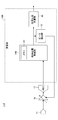
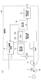
- FIG. 1 is a block diagram showing an example of a fetal heartbeat extracting device in the first embodiment.
- the fetal heartbeat extracting device 1-1 includes a calculation unit 10, an input terminal 11, an analog / digital converter (ADC) 12, a variable amplifier 16, and an ADC 17. And have.
- the calculation unit 10 includes a mother heart rate extraction unit 13, a maternal electrocardiogram removal unit 14, a peak detection unit 15, and a fetal heart rate calculation unit 18.
- the input signal input to the input terminal 11 includes a mother's heartbeat component and a fetal heartbeat component having a peak lower than the mother's heartbeat component.
- the input signal is detected and input to the input terminal 11 by, for example, a known method of mounting an electrode on the mother body and detecting an electrical signal on the body surface of the mother body.
- the input signal may be a signal indicating an electrocardiogram, for example.
- the first path is formed by the ADC 12 and the mother heart rate extracting unit 13, and supplies the input signal input to the input terminal 11 to the maternal electrocardiogram removing unit 14 via the ADC 12 and the mother heart rate extracting unit 15.
- the second path is formed by the variable amplifier 16 and the ADC 17, and an input signal input to the input terminal 11 is supplied to the maternal electrocardiogram removal unit 14 via the variable amplifier 16 and the ADC 17.
- the mother heart rate extraction unit 13 extracts a heart rate component of the mother from the input signal acquired through the ADC 12 and supplies the extracted heart rate component to the mother electrocardiogram removal unit 14.
- the maternal electrocardiogram removal unit 14 uses the peak detection unit 15 and the fetal heart rate calculation unit 18 as a signal obtained by removing the maternal heart rate component extracted by the maternal heart rate extraction unit 13 from the input signal acquired through the variable amplifier 16 and the ADC 17. To supply.
- the peak detection unit 15 detects the peak of the fetal heartbeat component from the signal output from the maternal electrocardiogram removal unit 14, and controls the variable amplifier 16 to a gain (ie, gain) corresponding to the detected peak amplitude. .
- the fetal heart rate calculation unit 18 calculates and outputs a fetal heart rate based on the signal output from the maternal electrocardiogram removal unit 14.
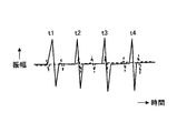
- FIG. 2 is a waveform diagram showing an example of an input signal indicating a heartbeat waveform including a maternal heartbeat and a fetal heartbeat.
- the vertical axis indicates signal amplitude in arbitrary units, and the horizontal axis indicates time in arbitrary units.
- the solid line indicates the maternal heart rate component, and the broken line indicates the fetal heart rate component.
- the peak of the heart rate component of the mother appears at times t1, t2, t3, t4,.
- the fetal heart rate component has a lower peak than the maternal heart rate component.
- the peak of the heart rate component of the fetus is very low, about 1/10 to 1/100, compared to the peak of the heart rate component of the mother.
- FIG. 3 is a waveform diagram for explaining an example of heart rate determination.
- the vertical axis indicates the amplitude of the input signal input to the input terminal 11 in arbitrary units, and the horizontal axis indicates time in arbitrary units.
- the P wave represents atrial excitement
- Q, R, and S represent ventricular excitement.
- the T wave represents a state in which the ventricle is depressed from excitement.
- the heart rate component is known based on, for example, the potential difference between PR, the potential difference between QR and the time interval, and the potential difference between RS and the time interval with reference to the peak of the R wave (R point). It can be extracted by the method.
- time information may be acquired by setting the range in which the heart rate component of the mother affects ⁇ ⁇ with the R point as a reference.
- ⁇ ⁇ is a parameter determined by the size of the heart.
- the mother heart rate extracting unit 13 extracts a heart rate component having a peak exceeding a certain threshold among heart rate components extracted from the input signal acquired through the ADC 12 of the first path as a heart rate component of the mother body. be able to.
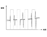
- FIG. 4 is a waveform diagram showing an example of an amplified heartbeat waveform.
- the vertical axis indicates the amplitude of the input signal supplied to the maternal electrocardiogram removal unit 14 via the second path in arbitrary units, and the horizontal axis indicates time in arbitrary units.
- the solid line indicates the maternal heart rate component
- the broken line indicates the fetal heart rate component.
- the peak of the heart rate component of the mother appears at times t1, t2, t3, t4,..., But the peak is saturated due to amplification by the variable amplifier 16.
- the fetal heartbeat component has a lower peak than the maternal heartbeat component, the peak is not saturated due to amplification in the variable amplifier 16. That is, the gain of the variable amplifier 16 is controlled so that the peak of the amplified fetal heartbeat component is not saturated, and the fetal heartbeat component can be obtained with high accuracy from the signal output from the ADC 17.
- FIG. 5 is a waveform diagram for explaining an example of fetal heartbeat extraction.
- the vertical axis indicates the amplitude of the signal output from the maternal electrocardiogram removal unit 14 in arbitrary units
- the horizontal axis indicates time in arbitrary units.
- the maternal electrocardiogram removing unit 14 is a diagram showing time information of the maternal heart rate component extracted by the maternal heart rate extracting unit 13 of the first path from the input signal shown in FIG. 4 acquired through the second path. By removing the blank areas ⁇ t 1, ⁇ t 2, ⁇ t 3, ⁇ t 4,..., The signal including the fetal heartbeat component is output.
- the time information acquired through the first path is used as the time information of the heart rate component of the mother, and the data of the corresponding portion of the time information is deleted. Since it is only necessary to know that the deleted data portion has been deleted, for example, data “0” may be substituted.
- 5 shows a state before the fetal heartbeat component is converted into a digital signal by the ADC 17 for convenience of explanation.
- the peak detection unit 15 includes a component having a peak that exceeds the first threshold in the signal waveform illustrated in FIG. 5 and an interval between peaks that exceeds the first threshold is less than the second threshold. It can be detected as a fetal heartbeat component. It is known in advance that the interval between the peaks of the fetal heart rate component is less than the second threshold.
- a signal for increasing the gain of the variable amplifier 16 by a constant value is supplied to the variable amplifier 16.
- a constant value for increasing the gain of the variable amplifier 16 can be arbitrarily set.
- the peak detector 15 can detect the peak exceeding the first threshold from the signal waveform shown in FIG.
- the gain of the variable amplifier 16 is decreased by a certain value.
- the signal to be supplied is supplied to the variable amplifier 16.
- the constant value that decreases the gain of the variable amplifier 16 can be arbitrarily set. That is, the peak detection unit 15 may be any unit that detects the peak of the acquired fetal heartbeat component and controls the gain according to the amplitude of the peak detected by the variable amplifier 16.
- the fetal heart rate calculation unit 18 can calculate and output the fetal heart rate from the signal waveform shown in FIG. 5 supplied from the maternal electrocardiogram removal unit 14.
- the heart beat component of the fetus disappears if the heart beat component of the mother is removed.
- the fetal heart rate component does not always disappear. Therefore, if the interval of the peak of the fetal heartbeat component is acquired at a plurality of locations (for example, 5 points), the heartbeat component of the fetus can be acquired. In addition, a portion where the peak interval is wide may be excluded from the calculation of the fetal heartbeat.
- a peak interval of 1.5 times or more of the preceding and following peak intervals is a portion removed together with the maternal heartbeat component waveform. Just do it.
- FIG. 6 is a diagram showing an example of a measured waveform of a heart rate waveform including a maternal heart rate and a fetal heart rate.
- the actually measured waveform shown in FIG. 6 is a signal indicating an electrocardiogram detected from the mother body by a known method and inputted to the input terminal 11.
- FIG. 7 is a diagram showing a simulation result of the amplified heartbeat waveform.
- FIG. 7 shows a waveform of a simulation result by a computer when the actually measured waveform shown in FIG. 6 is amplified with a gain of, for example, 4 times.
- the peak part of the mother's heartbeat that interferes with the extraction of the fetal heartbeat is shown surrounded by an elliptical broken line in FIG.
- FIG. 8 is a diagram showing a simulation result of the calculated fetal heartbeat.
- FIG. 8 shows a computer in which the heart rate peak portion of the maternal heart surrounded by an elliptical broken line in FIG. 7 is removed from the amplified heart rate waveform shown in FIG. 7 by the same process as the maternal electrocardiogram removal unit 14 described above. The waveform of the simulation result is shown.
- the heartbeat peak portion of ⁇ 0.04 seconds indicated by the oval dashed line in FIG. 7 is removed.
- a signal waveform capable of detecting the peak portion of the heartbeat component of the fetus indicated by being surrounded by an elliptical broken line in FIG. 8 can be acquired.
- the polarity of the heartbeat waveform of the mother and the polarity of the heartbeat waveform of the fetus are opposite to each other, and the peak of the heartbeat component of the mother appears on the lower side. The peak appears on the upper side.
- the maternal heartbeat waveform and the fetal heartbeat waveform are all shown by solid lines.
- FIG. 9 is a block diagram showing another example of the fetal heartbeat extracting device in the first embodiment. 9, parts that are the same as those shown in FIG. 1 are given the same reference numerals, and explanation thereof is omitted.
- the processing of the arithmetic unit 10 shown in FIG. 1 can be executed by a computer.
- the calculation unit 10A of the fetal heartbeat extracting device 1-1A includes a processor 101, a memory 102, a wired device 103, and a wireless device 104.
- the processor 101 and the memory 102 can form an example of a computer.
- the processor 101 can be formed by a CPU (Central Processing Unit), for example, and executes a program stored in the memory 102.
- CPU Central Processing Unit
- the memory 102 stores various data including results of arithmetic processing executed by the processor 101 in addition to programs executed by the processor 101.
- the memory 102 can be formed by, for example, a semiconductor storage device, a magnetic recording medium, an optical recording medium, a magneto-optical recording medium, or the like. Further, the memory 102 storing the program can form an example of a computer-readable storage medium.
- the wired device 103 outputs the fetal heart rate calculated by the processor 101 to an external device (not shown) such as a host device having a display device in a wired manner. Further, the wireless device 104 wirelessly outputs the fetal heartbeat calculated by the processor 101 to an external device. Note that the fetal heartbeat calculated by the processor 101 may be read after being stored in the memory 102 and supplied to the wireless device 104 (or the wired device 103).
- the fetal heartbeat extracting device 1-1A only needs to include at least one of the wired device 103 and the wireless device 104. Further, at least one of the wired device 103 and the wireless device 104 may be externally connected to the arithmetic unit 10A.
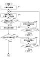
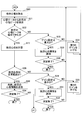
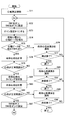
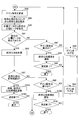
- FIGS. 10 and 11 are flowcharts for explaining an example of the fetal heartbeat extraction process in the first embodiment.
- the fetal heartbeat extraction process shown in FIGS. 10 and 11 can be executed by the processor 101 shown in FIG. 9 executing a program stored in the memory 102, for example.
- the processor 101 starts the electrocardiogram measurement in step S11, and acquires the input signal input to the input terminal 11 via the first path.
- the processor 101 extracts an electrocardiogram peak from the maternal electrocardiogram. Specifically, processing similar to that performed by the mother heart rate extracting unit 13 described with reference to FIG. 1 is performed, and the heart rate peak of the mother is extracted from the input signal.
- the processor 101 determines whether or not an electrocardiogram peak has been extracted. If the determination result is NO, the process proceeds to step S14, and if the determination result is YES, the process proceeds to step S16.
- step S14 the processor 101 notifies the external device via the wired device 103 or the wireless device 104 that the heart rate of the mother has not been detected.
- step S15 the processor 101 determines whether or not the electrocardiogram measurement is completed. If the determination result is NO, the process returns to step S12, and if the determination result is YES, the process ends.
- step S16 the processor 101 calculates the heart rate of the mother from the extracted peak.
- step S17 the processor 101 determines whether or not the measured heart rate of the mother is within the normal range. If the determination result is NO, the process proceeds to step S18, and if the determination result is YES, the process is The process proceeds to step S20 shown in FIG.
- the normal range of maternal heart rate refers to the range that the maternal heart rate can take.
- step S18 the processor 101 notifies the external device via the wired device 103 or the wireless device 104 that the heart rate of the mother is abnormal.
- step S19 the processor 101 determines whether or not the electrocardiogram measurement is completed. If the determination result is NO, the process returns to step S12, and if the determination result is YES, the process ends.
- the processor 101 removes the maternal electrocardiogram in step S20. Specifically, the same processing as that performed by the maternal electrocardiogram removal unit 14 described with reference to FIG. 1 is performed, and the heart rate component of the maternal body is removed from the input signal acquired through the second path.
- the processor 101 extracts a fetal electrocardiographic peak from the electrocardiographic data. Specifically, the same processing as that of the peak detection unit 15 described with reference to FIG. 1 is performed, and a signal (electrocardiographic data) obtained by removing the heart rate component of the mother from the input signal acquired through the second path is used. Detect the peak of the heart rate component. The processor 101 determines whether or not the peak of the fetal heartbeat component is detected in step S22. If the determination result is NO, the process proceeds to step S23, and if the determination result is YES, the process proceeds to step S27. move on.
- step S23 the processor 101 determines whether or not the gain setting is the maximum value. If the determination result is NO, the process proceeds to step S24, and if the determination result is YES, the process proceeds to step S25.
- step S24 the processor 101 increases the gain of the second path by a certain value, and the process returns to step S20.
- step S25 the processor 101 notifies the external device via the wired device 103 or the wireless device 104 that the fetal heartbeat is abnormal.
- step S26 the processor 101 determines whether or not the electrocardiogram measurement is completed. If the determination result is NO, the process returns to step S20, and if the determination result is YES, the process ends.
- step S27 the processor 101 performs the same processing as that of the fetal heart rate calculation unit 18 described with reference to FIG. 1, and calculates the fetal heart rate.
- step S28 the processor 101 determines whether or not the calculated fetal heartbeat is within the normal range. If the determination result is NO, the process proceeds to step S29, and if the determination result is YES, the process proceeds to step S29. Proceed to S33.
- the normal range of fetal heartbeat refers to the range that the fetal heartbeat can take.
- step S29 the processor 101 determines whether or not the gain setting is the minimum value. If the determination result is NO, the process proceeds to step S30, and if the determination result is YES, the process proceeds to step S31.
- step S30 the processor 101 decreases the gain of the second path by a certain value, and the process returns to step S20.
- the processor 101 notifies the external device via the wired device 103 or the wireless device 104 that the fetal heartbeat is abnormal.
- step S32 the processor 101 determines whether or not the electrocardiogram measurement is completed. If the determination result is NO, the process returns to step S20, and if the determination result is YES, the process ends.
- step S33 the processor 101 separately transmits the heart rate of the mother calculated in step S16 and the heart rate of the fetus calculated in step S27 to the external device via the wired device 103 or the wireless device 104. Note that only the heartbeat of the fetus may be transmitted to the external device.
- step S34 the processor 101 determines whether or not the electrocardiogram measurement is completed. If the determination result is NO, the process returns to step S11 shown in FIG. 10, and if the determination result is YES, the process ends. .
- FIG. 12 is a block diagram showing an example of a fetal heartbeat extracting device in the second embodiment.
- the processing of the calculation unit 10B may be executed by a computer. Further, at least one of the wired device 103 and the wireless device 104 illustrated in FIG. 9 may be provided.
- the maternal electrocardiogram removal unit 14 ⁇ / b> B removes the heart rate component of the maternal in which the peaks exceeding the threshold value continue for a certain period of time from the input signal acquired via the variable amplifier 16 and the ADC 17.
- the maternal electrocardiogram removal unit 14B includes a memory 141 that stores parameters including a threshold value used for removing the maternal heart rate component and a predetermined time.
- the value that the peak of the heart rate component of the mother can take exceeds the threshold value, and the fixed time that the peak exceeding the threshold value can continue is used.
- FIG. 13 is a waveform diagram showing an example of an amplified heartbeat waveform.
- the vertical axis indicates the amplitude of the input signal supplied to the maternal electrocardiogram removal unit 14B via the second path in arbitrary units, and the horizontal axis indicates time in arbitrary units.
- the solid line indicates the maternal heart rate component, and the broken line indicates the fetal heart rate component.
- the peak of the heart rate component of the mother is saturated exceeding the positive threshold Th Max as viewed from the ground level GND due to amplification in the variable amplifier 16, and exceeds the negative threshold Th Min. Saturated. Further, a certain time during which a peak exceeding the threshold (threshold Th Max in the example shown in FIG.
- the fetal heartbeat component has a lower peak than the maternal heartbeat component, the peak is not saturated due to amplification in the variable amplifier 16. That is, the gain of the variable amplifier 16 is controlled so that the peak of the amplified fetal heartbeat component is not saturated, and the fetal heartbeat component can be obtained with high accuracy from the signal output from the ADC 17.
- FIG. 14 is a waveform diagram showing an example of a fetal heartbeat.
- the vertical axis indicates the amplitude of the signal output from the maternal electrocardiogram removal unit 14 in arbitrary units, and the horizontal axis indicates time in arbitrary units.
- the maternal electrocardiogram removal unit 14 removes the heart rate component of the maternal body from which the peak exceeding the threshold value continues for a certain time indicated by the designated time t from the input signal shown in FIG. 13 acquired through the second path. Output a signal containing the fetal heartbeat component. Since it is only necessary to know that the deleted data portion has been deleted, for example, data “0” may be substituted. 14 shows a state before the heartbeat component of the fetus is converted into a digital signal by the ADC 17 for convenience of explanation.
- the processing of the calculation unit 10B shown in FIG. 12 can be executed by a computer. Therefore, a computer formed of the processor 101 and the memory 102 shown in FIG. 9 may be provided instead of the arithmetic unit 10B.
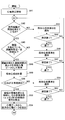
- FIGS. 15 and 16 are flowcharts for explaining an example of fetal heartbeat extraction processing in the second embodiment.
- the fetal heartbeat extraction process shown in FIGS. 15 and 16 can be executed, for example, when the processor 101 shown in FIG. 9 executes a program stored in the memory 102.
- the memory 102 also stores parameters stored in the memory 141 in the maternal electrocardiogram removal unit 14B shown in FIG.
- the processor 101 starts electrocardiogram measurement in step S41, and acquires the input signal input to the input terminal 11 via the second path.
- step S42 the processor 101 determines whether or not the amplitude of the input signal exceeds the threshold value. If the determination result is NO, the process proceeds to step S43. If the determination result is YES, the process proceeds to step S45. move on.
- step S43 the processor 101 notifies the external device via the wired device 103 or the wireless device 104 that the heart rate of the mother has not been detected.
- step S44 the processor 101 determines whether or not the electrocardiogram measurement is completed. If the determination result is NO, the process returns to step S42, and if the determination result is YES, the process ends.
- step S45 the processor 101 determines whether or not the continuous time in which the amplitude of the input signal exceeds the threshold is equal to or less than a predetermined time. If the determination result is NO, the process proceeds to step S46, and the determination result is If YES, the process proceeds to step S48.
- step S46 the processor 101 notifies the external device via the wired device 103 or the wireless device 104 that the heart rate of the mother is abnormal.
- step S47 the processor 101 determines whether or not the electrocardiogram measurement is completed. If the determination result is NO, the process returns to step S42, and if the determination result is YES, the process ends.
- step S48 the processor 101 acquires the middle of the continuous time when the amplitude of the input signal exceeds the threshold value as the maternal electrocardiographic peak, that is, the maternal heartbeat peak.
- step S49 the processor 101 calculates the heart rate of the mother from the extracted peak.
- step S50 the processor 101 determines whether or not the measured heart rate of the mother is within a normal range. If the determination result is NO, the process proceeds to step S51, and if the determination result is YES, the process is step. Proceed to S53.
- the normal range of maternal heart rate refers to the range that the maternal heart rate can take.
- step S51 the processor 101 notifies the external device via the wired device 103 or the wireless device 104 that the heart rate of the mother is abnormal.
- step S52 the processor 101 determines whether or not the electrocardiogram measurement is completed. If the determination result is NO, the process returns to step S42, and if the determination result is YES, the process ends.
- step S53 the processor 101 removes the signal only for the time when the amplitude of the input signal exceeds the threshold and the time before and after that ( ⁇ ⁇ milliseconds).
- step S54 the processor 101 extracts a fetal electrocardiographic peak from the electrocardiographic data. Specifically, the same processing as that of the peak detection unit 15 described with reference to FIG. 1 is performed, and a signal (electrocardiographic data) obtained by removing the heart rate component of the mother from the input signal acquired through the second path is used. Detect the peak of the heart rate component. After step S54, the process proceeds to step S55 shown in FIG.
- step S55 the processor 101 determines whether or not the peak of the fetal heartbeat component has been detected in step S55. If the determination result is NO, the process proceeds to step S56, and if the determination result is YES, the process proceeds to step S56. Advances to step S60. In step S56, the processor 101 determines whether or not the gain setting is the maximum value. If the determination result is NO, the process proceeds to step S57, and if the determination result is YES, the process proceeds to step S58. In step S57, the processor 101 increases the gain of the second path by a certain value, and the process returns to step S42 in FIG.
- step S58 the processor 101 notifies the external device via the wired device 103 or the wireless device 104 that the fetal heartbeat is abnormal.
- step S59 the processor 101 determines whether or not the electrocardiogram measurement is completed. If the determination result is NO, the process returns to step S42 in FIG. 15, and if the determination result is YES, the process ends.
- step S60 the processor 101 performs the same processing as that of the fetal heart rate calculating unit 18 described with reference to FIG. 1, and calculates the fetal heart rate.
- step S61 the processor 101 determines whether or not the calculated fetal heartbeat is within the normal range. If the determination result is NO, the process proceeds to step S62. If the determination result is YES, the process proceeds to step S62. Proceed to S66.
- the normal range of fetal heartbeat refers to the range that the fetal heartbeat can take.
- step S62 the processor 101 determines whether or not the gain setting is the minimum value. If the determination result is NO, the process proceeds to step S63, and if the determination result is YES, the process proceeds to step S64.
- step S63 the processor 101 decreases the gain of the second path by a certain value, and the process returns to step S42 in FIG.
- step S64 the processor 101 notifies the external device via the wired device 103 or the wireless device 104 that the fetal heartbeat is abnormal.
- step S65 the processor 101 determines whether or not the electrocardiogram measurement is completed. If the determination result is NO, the process returns to step S42 in FIG. 15, and if the determination result is YES, the process ends.
- step S66 the processor 101 separately transmits the heart rate of the mother calculated in step S49 and the heart rate of the fetus calculated in step S60 to the external device via the wired device 103 or the wireless device 104. Note that only the heartbeat of the fetus may be transmitted to the external device.
- step S67 the processor 101 determines whether or not the electrocardiogram measurement is completed. If the determination result is NO, the process returns to step S42 shown in FIG. 15, and if the determination result is YES, the process ends. .
- FIG. 17 is a block diagram showing an example of a fetal heartbeat extracting device in the third embodiment. In FIG. 17, the same parts as those in FIG.
- the processing of the calculation unit 10C may be executed by a computer. Further, at least one of the wired device 103 and the wireless device 104 illustrated in FIG. 9 may be provided. In the first embodiment, two paths are used. In the present embodiment, a single path is switched and used as the first path or the second path.
- the calculation unit 10C of the fetal heartbeat extraction circuit 1-3 includes a timing adjustment circuit 19 and switch circuits SW1 and SW2.
- the timing adjustment circuit 19 switches and controls the connection of the switch circuits SW1 and SW2.
- the timing adjustment circuit 19 variably controls the gain of the variable amplifier 16 based on the peak detected by the peak detector 15.
- the timing adjustment circuit 19 controls the gain of the variable amplifier 16 to, for example, 1 to control the switch circuit SW1 to be turned on (closed) and to switch the switch circuit SW2 to be turned off (open).
- the timing adjustment circuit 19 controls the gain of the variable amplifier 16 to 2 to 100, for example, and switches the switch circuit SW1 to OFF (open) and controls the switch circuit SW2 to ON (closed).
- an input signal is acquired via a variable amplifier 16 having a gain of 1 (that is, a setting not to be amplified) and an ADC 17, and maternal electrocardiogram removal is performed via an ON switch circuit SW1 and a mother heart rate extraction unit 13.
- the maternal electrocardiogram removal unit 14C stores the maternal heartbeat interval in the memory 142 in the maternal electrocardiogram removal unit 14C based on the maternal heartbeat extracted by the maternal heartbeat extraction unit 13.
- an input signal is acquired through the variable amplifier 16 and ADC 17 that are variably controlled to gain 2 or more, for example, and supplied to the maternal electrocardiogram removal unit 14C through the ON switch circuit SW2. .
- the maternal electrocardiogram removal unit 14C uses the peak detection unit 15 and the fetal heartbeat as a signal obtained by removing the maternal heart rate component extracted in the first state stored in the memory 142 from the input signal acquired in the second state. It supplies to the calculation part 18.
- the peak detection unit 15 detects a peak of the fetal heartbeat component from the signal output from the maternal electrocardiogram removal unit 14, and controls a signal for controlling the gain according to the amplitude of the peak detected by the variable amplifier 16, The voltage is supplied to the variable amplifier 16 via the timing adjustment circuit 19.
- the processing of the calculation unit 10C shown in FIG. 17 can be executed by a computer. Therefore, a computer formed of the processor 101 and the memory 102 shown in FIG. 9 may be provided instead of the arithmetic unit 10C. In this case, the computer executes processing of the mother heart rate extraction unit 13, the maternal electrocardiogram removal unit 14C, the peak detection unit 15, the fetal heart rate calculation unit 18, and the timing adjustment circuit 19, and controls the switching of the switch circuits SW1 and SW2. To do.
- FIGS. 18 and 19 are flowcharts for explaining an example of fetal heartbeat extraction processing in the third embodiment.
- the fetal heartbeat extraction process shown in FIGS. 18 and 19 can be executed by the processor 101 shown in FIG. 9 executing a program stored in the memory 102, for example.
- step S71 the processor 101 starts electrocardiogram measurement, and acquires the input signal input to the input terminal 11 by the arithmetic unit 10C.
- step S72 the processor 101 controls the switch circuit SW1 to be on and the switch circuit SW2 to be off.
- the processor 101 sets the gain setting of the variable amplifier 16 to 1 in step S73.
- step S74 the processor 101 extracts an electrocardiogram peak from the maternal electrocardiogram. Specifically, the same processing as that performed by the mother heartbeat extracting unit 13 described with reference to FIG. 1 is performed to extract the peak of the mother's heartbeat from the input signal.
- step S75 the processor 101 determines whether or not an electrocardiogram peak has been extracted.
- step S76 the processor 101 notifies the external device via the wired device 103 or the wireless device 104 that the heart rate of the mother has not been detected.
- step S77 the processor 101 determines whether or not the electrocardiogram measurement is completed. If the determination result is NO, the process returns to step S72, and if the determination result is YES, the process ends.
- step S78 the processor 101 calculates the heart rate of the mother from the extracted peak.
- step S79 the processor 101 determines whether or not the measured heart rate of the mother is within the normal range. If the determination result is NO, the process proceeds to step S80, and if the determination result is YES, the process is step. Proceed to S82.
- the normal range of maternal heart rate refers to the range that the maternal heart rate can take.
- step S80 the processor 101 notifies the external device via the wired device 103 or the wireless device 104 that the heart rate of the mother is abnormal.
- step S81 the processor 101 determines whether or not the electrocardiogram measurement is completed. If the determination result is NO, the process returns to step S72, and if the determination result is YES, the process ends.
- the processor 101 stores the maternal heartbeat timing in the memory 102 in step S82.
- step S ⁇ b> 83 the processor 101 calculates the maternal heart rate based on the maternal heart rate timing stored in the memory 102.
- step S84 the processor 101 determines whether or not the measured heart rate of the mother is within the normal range. If the determination result is NO, the process proceeds to step S85, and if the determination result is YES, the process is step. Proceed to S87.
- step S85 the processor 101 notifies the external device via the wired device 103 or the wireless device 104 that the heart rate of the mother is abnormal.
- step S86 the processor 101 determines whether or not the electrocardiogram measurement is completed. If the determination result is NO, the process returns to step S72, and if the determination result is YES, the process ends.
- step S87 the processor 101 controls the switch circuit SW1 to be turned off and the switch circuit SW2 to be turned on, and the process proceeds to step S88 shown in FIG. In FIG. 19, the processor 101 changes the gain setting of the variable amplifier 16 to a value other than 1 in step S88.
- step S89 the processor 101 removes the maternal electrocardiogram. Specifically, the same processing as that performed by the maternal electrocardiogram removal unit 14 described with reference to FIG. 1 is performed, and the maternal electrocardiogram is input from an input signal amplified by a gain other than 1 based on the maternal heartbeat timing stored in the memory 102. Remove the heart rate component.
- step S90 the processor 101 extracts a fetal electrocardiographic peak from the electrocardiographic data.
- the same processing as that of the peak detection unit 15 described with reference to FIG. 1 is performed, and the heartbeat of the fetus is obtained from a signal (electrocardiographic data) obtained by removing the maternal heartbeat component from the input signal amplified with a gain other than 1.
- the peak of the component is detected.
- the processor 101 determines whether or not the peak of the fetal heartbeat component is detected in step S91. If the determination result is NO, the process proceeds to step S92. If the determination result is YES, the process proceeds to step S96. move on.
- step S92 the processor 101 determines whether or not the gain setting is the maximum value. If the determination result is NO, the process proceeds to step S93. If the determination result is YES, the process proceeds to step S94. In step S93, the processor 101 increases the gain of the variable amplifier 16 by a fixed value, and the process returns to step S88. In step S94, the processor 101 notifies the external device via the wired device 103 or the wireless device 104 that the fetal heartbeat is abnormal. In step S95, the processor 101 determines whether or not the electrocardiogram measurement is completed. If the determination result is NO, the process returns to step S88, and if the determination result is YES, the process ends.
- step S96 the processor 101 performs the same processing as that of the fetal heart rate calculation unit 18 described with reference to FIG. 1, and calculates the fetal heart rate.
- step S97 the processor 101 determines whether or not the calculated fetal heartbeat is within the normal range. If the determination result is NO, the process proceeds to step S98, and if the determination result is YES, the process proceeds to step S98. Proceed to S102.
- the normal range of fetal heartbeat refers to the range that the fetal heartbeat can take.
- step S98 the processor 101 determines whether or not the gain setting is the minimum value. If the determination result is NO, the process proceeds to step S99, and if the determination result is YES, the process proceeds to step S100.
- step S99 the processor 101 decreases the gain of the variable amplifier 16 by a fixed value, and the process returns to step S88.
- step S100 the processor 101 notifies the external device via the wired device 103 or the wireless device 104 that the fetal heartbeat is abnormal.
- step S101 the processor 101 determines whether or not the electrocardiogram measurement is completed. If the determination result is NO, the process returns to step S88, and if the determination result is YES, the process ends.
- step S102 the processor 101 separately transmits the heart rate of the mother calculated in step S83 and the heart rate of the fetus calculated in step S96 to the external device via the wired device 103 or the wireless device 104. Note that only the heartbeat of the fetus may be transmitted to the external device.
- step S103 the processor 101 determines whether or not the electrocardiogram measurement is completed. If the determination result is NO, the process returns to step S72 shown in FIG. 18, and if the determination result is YES, the process ends. .
- the configuration of the fetal heartbeat extracting device 1-3 is the same as that of the fetal heartbeat extracting device 1-1 of the first embodiment.
- the configuration can be simplified. Further, in the processing of the calculation unit 10C, it is possible to reduce the load on the calculation unit 10C by suppressing the calculation amount as in the case of the calculation unit 10 (or calculation unit 10A) of the first embodiment.
- the load on the calculation unit can be reduced.
- the heart rate of the fetus can be extracted with high accuracy.
- the calculation unit can be reduced in size. For this reason, it is possible to reduce the size, cost and power consumption of the fetal heart rate extraction device, and it is also possible to form a wearable fetal heart rate extraction device.
- an input signal in which the maternal heartbeat component and the fetal heartbeat component are mixed is transmitted to the host device.
- power consumption can be reduced by reducing the amount of communication with the host device. For example, when an input signal in which a maternal heart rate component and a fetal heart rate component are mixed using a 16-bit resolution ADC with 200 Hz sampling is transmitted wirelessly, it is necessary to transmit data at 3.2 kbps. For example, if only 8-bit data is transmitted at 1 Hz, the data amount can be suppressed to 1/100.
- the amount of communication increases, so the load on the communication processing is increased and the possibility that data is interrupted increases.
- the amount of communication is large, the communication time becomes long, and it is difficult to reduce the burden and stress on the mother.
- the sampling time is reduced in order to lighten the communication processing load, the heartbeat extraction accuracy is lowered.
- the fetal heartbeat component may be lost.
- the communication amount can be reduced and the communication time can be shortened, so that the burden and stress on the mother can be reduced.
Landscapes
- Health & Medical Sciences (AREA)
- Life Sciences & Earth Sciences (AREA)
- Cardiology (AREA)
- Engineering & Computer Science (AREA)
- Molecular Biology (AREA)
- Medical Informatics (AREA)
- Veterinary Medicine (AREA)
- Biophysics (AREA)
- Pathology (AREA)
- Biomedical Technology (AREA)
- Heart & Thoracic Surgery (AREA)
- Physics & Mathematics (AREA)
- Public Health (AREA)
- Surgery (AREA)
- Animal Behavior & Ethology (AREA)
- General Health & Medical Sciences (AREA)
- Signal Processing (AREA)
- Physiology (AREA)
- Measurement And Recording Of Electrical Phenomena And Electrical Characteristics Of The Living Body (AREA)
Abstract
胎児心拍抽出装置は、母体の心拍成分と胎児の心拍成分とが混在する入力信号を増幅する可変増幅器と、前記入力信号から前記母体の心拍成分を除去して前記胎児の心拍成分を取得する取得部と、取得した前記胎児の心拍成分のピークを検出して前記可変増幅器を前記ピークの振幅に応じたゲインに制御するピーク検出部と、を備える。
Description
本発明は、胎児心拍抽出装置、方法及びプログラムに関する。
妊娠中の胎児の成長を胎児の心拍で確認することは、一般的に行われている。多くの医療機関では、妊娠確認のために、超音波診断により母体の腹部から胎児の様子と胎児の心拍を確認する。正常妊娠の場合、妊娠週数が8週間になれば胎児心拍動が全例で確認できる。また、流産の可能性についても、胎児心拍で確認することができる。このように、胎児心拍は、妊娠中の診断において取得する有用な情報の1つである。
胎児心拍は、超音波診断の他に、胎児の心臓から発生した電気信号を母体の体表面で検知して心電図を取得する方法によっても取得できる。超音波診断では、超音波を胎児に当てることから、特別な診断装置と、診断装置を扱う知識を有する操作者が必要である。これに対し、母体の体表面の電気信号を検出する方法では、母体に電極を装着するだけで、比較的簡単な装置を用いて胎児の心電図を取得できる。
母体の体表面の電気信号を検出する方法で取得した心電図には、母体の心拍成分と胎児の心拍成分とが混在しているため、胎児心拍を取得するためには心電図に信号処理を施す必要がある。しかし、胎児の心拍成分のピークは、母体の心拍成分のピークに比べて1/10~1/100程度と低い。このため、母体の心拍成分に比べてピークが非常に小さい胎児の心拍成分を、母体の心拍成分と胎児の心拍成分とが混在している心電図から抽出するには、演算部において複雑な演算を行わなければならず、演算部への負荷を軽減することは難しい。
例えば、アナログ電気信号をデジタル電気信号に変換する際の分解能を落とすことで、演算部において行う演算量を減らして演算部への負荷を軽減することは可能である。しかし、この場合、分解能を落としたことで胎児心拍の情報の一部が欠落すると、胎児の心電図の信頼性が低下するので、正確な胎児心拍を抽出することは難しい。
従来の胎児心拍抽出方法では、演算部への負荷を軽減することが難しい。
そこで、本発明は、演算部への負荷を軽減することができる胎児心拍抽出装置、方法及びプログラムを提供することを目的とする。
本発明の一側面によれば、母体の心拍成分と胎児の心拍成分とが混在する入力信号を増幅する可変増幅器と、前記入力信号から前記母体の心拍成分を除去して前記胎児の心拍成分を取得する取得部と、取得した前記胎児の心拍成分のピークを検出して前記可変増幅器を前記ピークの振幅に応じたゲインに制御するピーク検出部と、を備えた胎児心拍抽出装置が提供される。
一態様によれば、演算部への負荷を軽減することが可能となる。
開示の胎児心拍抽出装置、方法及びプログラムでは、母体の心拍成分と胎児の心拍成分とが混在する入力信号を可変増幅器で増幅し、入力信号から母体の心拍成分を除去して胎児の心拍成分を取得し、取得した胎児の心拍成分のピークを検出して可変増幅器をピークの振幅に応じたゲインに制御する。
以下に、開示の胎児心拍抽出装置、方法及びプログラムの各実施例を図面と共に説明する。
(第1実施例)
図1は、第1実施例における胎児心拍抽出装置の一例を示すブロック図である。図1に示すように、胎児心拍抽出装置1-1は、演算部10と、入力端子11と、アナログ/デジタル変換器(ADC:Analog-to-Digital Converter)12と、可変増幅器16と、ADC17とを有する。演算部10は、母心拍抽出部13、母体心電除去部14と、ピーク検出部15と、胎児心拍計算部18とを含む。入力端子11に入力される入力信号には、母体の心拍成分と、母体の心拍成分より低いピークを有する胎児の心拍成分とが混在する。入力信号は、例えば母体に電極を装着して母体の体表面の電気信号を検出する周知の方法により検出されて入力端子11に入力される。入力信号は、例えば心電図を示す信号であっても良い。
図1は、第1実施例における胎児心拍抽出装置の一例を示すブロック図である。図1に示すように、胎児心拍抽出装置1-1は、演算部10と、入力端子11と、アナログ/デジタル変換器(ADC:Analog-to-Digital Converter)12と、可変増幅器16と、ADC17とを有する。演算部10は、母心拍抽出部13、母体心電除去部14と、ピーク検出部15と、胎児心拍計算部18とを含む。入力端子11に入力される入力信号には、母体の心拍成分と、母体の心拍成分より低いピークを有する胎児の心拍成分とが混在する。入力信号は、例えば母体に電極を装着して母体の体表面の電気信号を検出する周知の方法により検出されて入力端子11に入力される。入力信号は、例えば心電図を示す信号であっても良い。
第1のパスは、ADC12及び母心拍抽出部13で形成され、入力端子11に入力された入力信号を、ADC12及び母心拍抽出部15を介して母体心電除去部14に供給する。他方、第2のパスは、可変増幅器16及びADC17で形成され、入力端子11に入力された入力信号を、可変増幅器16及びADC17を介して母体心電除去部14に供給する。
母心拍抽出部13は、ADC12を介して取得した入力信号から、母体の心拍成分を抽出して母体心電除去部14に供給する。母体心電除去部14は、可変増幅器16及びADC17を介して取得した入力信号から、母心拍抽出部13で抽出された母体の心拍成分を除去した信号をピーク検出部15及び胎児心拍計算部18に供給する。ピーク検出部15は、母体心電除去部14が出力する信号から、胎児の心拍成分のピークを検出して、可変増幅器16を検出したピークの振幅に応じたゲイン(即ち、利得)に制御する。また、胎児心拍計算部18は、母体心電除去部14が出力する信号に基づき、胎児心拍を計算して出力する。
図2は、母体心拍及び胎児心拍を含む心拍波形を示す入力信号の一例を示す波形図である。図2中、縦軸は信号の振幅を任意単位で示し、横軸は時間を任意単位で示す。図2において、実線は母体の心拍成分を示し、破線は胎児の心拍成分を示す。図2に示す例では、時刻t1,t2,t3,t4,...で母体の心拍成分のピークが現れている。これに対し、胎児の心拍成分は、母体の心拍成分より低いピークを有する。胎児の心拍成分のピークは、母体の心拍成分のピークに比べて1/10~1/100程度と非常に低い。
図3は、心拍の判定の一例を説明する波形図である。図3中、縦軸は入力端子11に入力される入力信号の振幅を任意単位で示し、横軸は時間を任意単位で示す。図3において、P波は心房の興奮を表し、Q,R,Sは心室の興奮を表している。また、T波は心室が興奮からさめる様子を表す。心拍成分は、例えばR波の山(R点)を基準として、P-R間の電位差、Q-R間の電位差と時間間隔、及びR-S間の電位差と時間間隔などに基づき、周知の方法により抽出することができる。
なお、R点を基準として、母体の心拍成分が影響する範囲を±αとして時間情報を取得しても良い。ここで、±αは、心臓の大きさで決められるパラメータである。また、母体の心拍成分のピークは、胎児の心拍成分のピークに比べて高く、一定閾値を超えることが予めわかっている。このため、母心拍抽出部13は、第1のパスのADC12を介して取得した入力信号から抽出された心拍成分のうち、一定閾値を超えるピークを有する心拍成分を、母体の心拍成分として抽出することができる。
図4は、増幅された心拍波形の一例を示す波形図である。図4中、縦軸は第2のパスを介して母体心電除去部14に供給される入力信号の振幅を任意単位で示し、横軸は時間を任意単位で示す。図4において、実線は母体の心拍成分を示し、破線は胎児の心拍成分を示す。図4に示す例では、時刻t1,t2,t3,t4,...で母体の心拍成分のピークが現れているが、可変増幅器16における増幅によりピークが飽和している。これに対し、胎児の心拍成分は、母体の心拍成分より低いピークを有するため、可変増幅器16における増幅によりピークが飽和していない。つまり、可変増幅器16のゲインは、増幅された胎児の心拍成分のピークが飽和しない程度に制御されており、ADC17が出力する信号からは、胎児の心拍成分を高精度で取得することができる。
図5は、胎児心拍の抽出の一例を説明する波形図である。図5中、縦軸は母体心電除去部14から出力される信号の振幅を任意単位で示し、横軸は時間を任意単位で示す。母体心電除去部14は、第2のパスを介して取得される図4に示す入力信号から、第1のパスの母心拍抽出部13で抽出された母体の心拍成分の時間情報が示す図5中破線の空白区間Δt1,Δt2,Δt3,Δt4,...を除去することで、胎児の心拍成分を含む信号を出力する。つまり、母体の心拍成分の時間情報には、第1のパスを介して取得した時間情報を使い、その時間情報の該当箇所のデータを削除する。削除されたデータの箇所は、削除されたことが分かれば良いので、例えばデータ「0」を代入すれば良い。なお、図5では、説明の便宜上、胎児の心拍成分がADC17によりデジタル信号に変換される前の状態を示す。
ピーク検出部15は、図5に示す信号波形のうち、ピークが第1の閾値を超えており、且つ、第1の閾値を超えているピーク間の間隔が第2の閾値未満である成分を、胎児の心拍成分として検出することができる。胎児の心拍成分のピーク間の間隔は、第2の閾値未満となることが予めわかっている。ここで、ピーク検出部15が図5に示す信号波形から、第1の閾値を超えるピークを検出できない場合には、可変増幅器16のゲインを一定値だけ増加させる信号を可変増幅器16に供給する。可変増幅器16のゲインを増加させる一定値は、任意に設定可能である。一方、ピーク検出部15が図5に示す信号波形から、第1の閾値を超えるピークを検出できるものの、ピークが高すぎて飽和している場合には、可変増幅器16のゲインを一定値だけ減少させる信号を可変増幅器16に供給する。可変増幅器16のゲインを減少させる一定値は、任意に設定可能である。つまり、ピーク検出部15は、取得した胎児の心拍成分のピークを検出して可変増幅器16を検出したピークの振幅に応じたゲインに制御するものであれば良い。
胎児の心拍成分のピークが検出できる信号波形になれば、母体の心拍成分の場合と同様に、R点を基準として胎児の心拍成分を抽出することができる。従って、胎児心拍計算部18は、母体心電除去部14から供給される図5に示す信号波形から、胎児心拍を計算して出力することができる。
なお、母体の心拍のタイミングと胎児の心拍のタイミングとが同じ場合、母体の心拍成分を除去すると、胎児の心拍成分が消失してしまう。しかし、母体の心拍数と胎児の心拍数は異なるため、胎児の心拍成分が常に消失することはない。従って、複数個所(例えば5点)で胎児の心拍成分のピークの間隔を取得すれば、胎児の心拍成分を取得することができる。また、ピーク間隔が広い個所は、胎児心拍の計算から除外すれば良い。具体的には、胎児心拍の計算から除外する判断基準として、前後のピーク間隔の1.5倍以上のピーク間隔の箇所は、母体の心拍成分の波形と一緒に除去された箇所であると判断すれば良い。
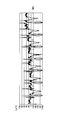
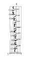
図6は、母体心拍及び胎児心拍を含む心拍波形の実測波形の一例を示す図である。図6に示す実測波形は、母体から周知の方法で検出されて入力端子11に入力された心電図を示す信号である。図7は、増幅された心拍波形のシミュレーション結果を示す図である。図7は、図6に示す実測波形を例えば4倍のゲインで増幅した場合のコンピュータによるシミュレーション結果の波形を示す。胎児の心拍を抽出するのに邪魔になる母体の心拍のピーク部分は、図7中、楕円の破線で囲んで示す。
図8は、計算された胎児心拍のシミュレーション結果を示す図である。図8は、図7に示す増幅された心拍波形から、図7中楕円の破線で囲んで示す母体の心拍のピーク部分を上記の母体心電除去部14と同様の処理により除去した、コンピュータによるシミュレーションの結果の波形を示す。この例では、図7に示す増幅された心拍波形から、図7中楕円の破線で囲んで示す母体の心拍のピーク部分±0.04秒の区間を除去した。これにより、図8中楕円の破線で囲んで示す胎児の心拍成分のピーク部分が検出できる信号波形が取得可能であることが確認された。
なお、図6乃至図8では、母体の心拍波形の極性と胎児の心拍波形の極性とが、互いに逆極性になっており、母体の心拍成分のピークは下側に現れ、胎児の心拍成分のピークは上側に現れている。また、図6乃至図8では、母体の心拍波形及び胎児の心拍波形を全て実線で示している。
図9は、第1実施例における胎児心拍抽出装置の他の例を示すブロック図である。図9中、図1と同一部分には同一符号を付し、その説明は省略する。図1に示す演算部10の処理は、コンピュータにより実行可能である。この例では、胎児心拍抽出装置1-1Aの演算部10Aは、プロセッサ101と、メモリ102と、有線デバイス103と、無線装置104とを含む。プロセッサ101及びメモリ102は、コンピュータの一例を形成可能である。プロセッサ101は、例えばCPU(Central Processing Unit)などにより形成可能であり、メモリ102に記憶されたプログラムを実行する。メモリ102は、プロセッサ101が実行するプログラムに加え、プロセッサ101が実行する演算処理の結果などを含む各種データを記憶する。メモリ102は、例えば半導体記憶装置、磁気記録媒体、光記録媒体、光磁気記録媒体などにより形成可能である。また、プログラムを記憶したメモリ102は、コンピュータ読み取り可能な記憶媒体の一例を形成可能である。
有線デバイス103は、プロセッサ101が計算した胎児心拍を、有線で例えば表示装置を有するホスト装置などの外部装置(図示せず)へ出力する。また、無線デバイス104は、プロセッサ101が計算した胎児心拍を、無線で外部装置へ出力する。なお、プロセッサ101が計算した胎児心拍は、メモリ102に記憶した後読み出されて無線装置104(または、有線デバイス103)に供給されるようにしても良い。なお、胎児心拍抽出装置1-1Aには、有線デバイス103及び無線装置104のうち少なくとも一方が設けられていれば良い。また、有線デバイス103及び無線装置104のうち少なくとも一方は、演算部10Aに対して外部接続されていても良い。
図10及び図11は、第1実施例における胎児心拍抽出処理の一例を説明するフローチャートである。図10及び図11に示す胎児心拍抽出処理は、例えば図9に示すプロセッサ101がメモリ102に記憶されたプログラムを実行することにより実行可能である。
図10中、プロセッサ101は、ステップS11において、心電測定を開始し、入力端子11に入力された入力信号を第1のパスを介して取得する。プロセッサ101は、ステップS12において、母体心電から心電ピークを抽出する。具体的には、図1と共に説明した母心拍抽出部13と同様の処理を行い、入力信号から母体の心拍のピークを抽出する。プロセッサ101は、ステップS13において、心電ピークが抽出できたか否かを判定し、判定結果がNOであると処理はステップS14へ進み、判定結果がYESであると処理はステップS16へ進む。プロセッサ101は、ステップS14において、母体の心拍が未検出である旨を有線デバイス103または無線装置104を介して外部装置へ通知する。プロセッサ101は、ステップS15において、心電測定が終了したか否かを判定し、判定結果がNOであると処理はステップS12へ戻り、判定結果がYESであると処理は終了する。
プロセッサ101は、ステップS16において、抽出したピークから母体の心拍を計算する。プロセッサ101は、ステップS17において、計測した母体の心拍が正常範囲内であるか否かを判定し、判定結果がNOであると処理はステップS18へ進み、判定結果がYESであると処理は図11に示すステップS20へ進む。母体の心拍の正常範囲とは、母体の心拍が取り得る範囲を指す。プロセッサ101は、ステップS18において、母体の心拍が異常である旨を有線デバイス103または無線装置104を介して外部装置へ通知する。プロセッサ101は、ステップS19において、心電測定が終了したか否かを判定し、判定結果がNOであると処理はステップS12へ戻り、判定結果がYESであると処理は終了する。
図11中、プロセッサ101は、ステップS20において、母体心電を除去する。具体的には、図1と共に説明した母体心電除去部14と同様の処理を行い、第2のパスを介して取得した入力信号から母体の心拍成分を除去する。プロセッサ101は、ステップS21において、心電データから胎児の心電ピークを抽出する。具体的には、図1と共に説明したピーク検出部15と同様の処理を行い、第2のパスを介して取得した入力信号から母体の心拍成分を除去した信号(心電データ)から、胎児の心拍成分のピークを検出する。プロセッサ101は、ステップS22において、胎児の心拍成分のピークが検出されたか否かを判定し、判定結果がNOであると処理はステップS23へ進み、判定結果がYESであると処理はステップS27へ進む。
プロセッサ101は、ステップS23において、ゲイン設定が最大値であるか否かを判定し、判定結果がNOであると処理はステップS24へ進み、判定結果がYESであると処理はステップS25へ進む。プロセッサ101は、ステップS24において、第2のパスのゲインを一定値だけ増加し、処理はステップS20へ戻る。プロセッサ101は、ステップS25において、胎児の心拍が異常である旨を有線デバイス103または無線装置104を介して外部装置へ通知する。プロセッサ101は、ステップS26において、心電測定が終了したか否かを判定し、判定結果がNOであると処理はステップS20へ戻り、判定結果がYESであると処理は終了する。
プロセッサ101は、ステップS27において、図1と共に説明した胎児心拍計算部18と同様の処理を行い、胎児の心拍を計算する。プロセッサ101は、ステップS28において、計算した胎児の心拍が正常範囲内であるか否かを判定し、判定結果がNOであると処理はステップS29へ進み、判定結果がYESであると処理はステップS33へ進む。胎児の心拍の正常範囲とは、胎児の心拍が取り得る範囲を指す。プロセッサ101は、ステップS29において、ゲイン設定が最小値であるか否かを判定し、判定結果がNOであると処理はステップS30へ進み、判定結果がYESであると処理はステップS31へ進む。プロセッサ101は、ステップS30において、第2のパスのゲインを一定値だけ減少させ、処理はステップS20へ戻る。プロセッサ101は、ステップS31において、胎児の心拍が異常である旨を有線デバイス103または無線装置104を介して外部装置へ通知する。プロセッサ101は、ステップS32において、心電測定が終了したか否かを判定し、判定結果がNOであると処理はステップS20へ戻り、判定結果がYESであると処理は終了する。
プロセッサ101は、ステップS33において、ステップS16で計算された母体の心拍と、ステップS27で計算された胎児の心拍とを別々に、有線デバイス103または無線装置104を介して外部装置へ送信する。なお、胎児の心拍のみを外部装置へ送信するようにしても良い。プロセッサ101は、ステップS34において、心電測定が終了したか否かを判定し、判定結果がNOであると処理は図10に示すステップS11へ戻り、判定結果がYESであると処理は終了する。
本実施例によれば、比較的簡単な演算を行うことで、母体の心拍成分と胎児の心拍成分とが混在している心電図から胎児の心拍成分を抽出することができる。このため、演算部10(または、演算部10A)の演算量を抑えて、演算部10(または、演算部10A)への負荷を軽減することが可能となる。また、元のアナログ波形の入力信号から母体の心拍成分を除去することで、より鮮明な胎児の心拍成分を抽出することができる。
(第2実施例)
図12は、第2実施例における胎児心拍抽出装置の一例を示すブロック図である。図12中、図1と同一部分には同一符号を付し、その説明は省略する。本実施例においても、演算部10Bの処理をコンピュータにより実行しても良い。また、図9に示す有線デバイス103及び無線装置104のうち少なくとも一方が設けられていても良い。
(第2実施例)
図12は、第2実施例における胎児心拍抽出装置の一例を示すブロック図である。図12中、図1と同一部分には同一符号を付し、その説明は省略する。本実施例においても、演算部10Bの処理をコンピュータにより実行しても良い。また、図9に示す有線デバイス103及び無線装置104のうち少なくとも一方が設けられていても良い。
本実施例では、上記第1実施例における第1のパスが設けられていない。また、母体心電除去部14Bは、可変増幅器16及びADC17を介して取得した入力信号のうち、閾値を超えるピークが一定時間連続する母体の心拍成分を除去する。母体心電除去部14Bは、この母体の心拍成分の除去で用いる閾値と一定時間とを含むパラメータを記憶したメモリ141を有する。このように、本実施例では、母体の心拍成分のピークが取り得る値が閾値を超えることと、閾値を超えるピークが連続し得る一定時間とを利用する。
図13は、増幅された心拍波形の一例を示す波形図である。図13中、縦軸は第2のパスを介して母体心電除去部14Bに供給される入力信号の振幅を任意単位で示し、横軸は時間を任意単位で示す。図13において、実線は母体の心拍成分を示し、破線は胎児の心拍成分を示す。図13に示す例では、母体の心拍成分のピークが、可変増幅器16における増幅により接地レベルGNDから見て正側の閾値ThMaxを超えて飽和しており、負側の閾値ThMinを超えて飽和している。また、閾値(図13に示す例では閾値ThMax)を超えるピークが連続し得る一定時間は、指定時間tで示されている。これに対し、胎児の心拍成分は、母体の心拍成分より低いピークを有するため、可変増幅器16における増幅によりピークが飽和していない。つまり、可変増幅器16のゲインは、増幅された胎児の心拍成分のピークが飽和しない程度に制御されており、ADC17が出力する信号からは、胎児の心拍成分を高精度で取得することができる。
図14は、胎児心拍の一例を示す波形図である。図5中、縦軸は母体心電除去部14から出力される信号の振幅を任意単位で示し、横軸は時間を任意単位で示す。母体心電除去部14は、第2のパスを介して取得される図13に示す入力信号から、閾値を超えるピークが指定時間tで示される一定時間連続する母体の心拍成分を除去することで、胎児の心拍成分を含む信号を出力する。削除されたデータの箇所は、削除されたことが分かれば良いので、例えばデータ「0」を代入すれば良い。なお、図14では、説明の便宜上、胎児の心拍成分がADC17によりデジタル信号に変換される前の状態を示す。
図12に示す演算部10Bの処理は、コンピュータにより実行可能である。従って、演算部10Bの代わりに、図9に示すプロセッサ101及びメモリ102で形成されたコンピュータを設けても良い。
図15及び図16は、第2実施例における胎児心拍抽出処理の一例を説明するフローチャートである。図15及び図16に示す胎児心拍抽出処理は、例えば図9に示すプロセッサ101がメモリ102に記憶されたプログラムを実行することにより実行可能である。この場合、メモリ102は、図12に示す母体心電除去部14B内のメモリ141が記憶するパラメータをも記憶する。
図15中、プロセッサ101は、ステップS41において、心電測定を開始し、入力端子11に入力された入力信号を第2のパスを介して取得する。プロセッサ101は、ステップS42において、入力信号の振幅が閾値を超えているか否かを判定し、判定結果がNOであると処理はステップS43へ進み、判定結果がYESであると処理はステップS45へ進む。プロセッサ101は、ステップS43において、母体の心拍が未検出である旨を有線デバイス103または無線装置104を介して外部装置へ通知する。プロセッサ101は、ステップS44において、心電測定が終了したか否かを判定し、判定結果がNOであると処理はステップS42へ戻り、判定結果がYESであると処理は終了する。
プロセッサ101は、ステップS45において、入力信号の振幅が閾値を超えている連続時間が一定時間以下であるか否かを判定し、判定結果がNOであると処理はステップS46へ進み、判定結果がYESであると処理はステップS48へ進む。プロセッサ101は、ステップS46において、母体の心拍が異常である旨を有線デバイス103または無線装置104を介して外部装置へ通知する。プロセッサ101は、ステップS47において、心電測定が終了したか否かを判定し、判定結果がNOであると処理はステップS42へ戻り、判定結果がYESであると処理は終了する。
プロセッサ101は、ステップS48において、入力信号の振幅が閾値を超えた連続時間の真ん中を母体心電ピーク、即ち、母体の心拍のピークとして取得する。プロセッサ101は、ステップS49において、抽出したピークから母体の心拍を計算する。プロセッサ101は、ステップS50において、計測した母体の心拍が正常範囲内であるか否かを判定し、判定結果がNOであると処理はステップS51へ進み、判定結果がYESであると処理はステップS53へ進む。母体の心拍の正常範囲とは、母体の心拍が取り得る範囲を指す。プロセッサ101は、ステップS51において、母体の心拍が異常である旨を有線デバイス103または無線装置104を介して外部装置へ通知する。プロセッサ101は、ステップS52において、心電測定が終了したか否かを判定し、判定結果がNOであると処理はステップS42へ戻り、判定結果がYESであると処理は終了する。
プロセッサ101は、ステップS53において、入力信号の振幅が閾値を超える時間と、その前後の時間(±αミリ秒)の時間だけ信号を除去する。プロセッサ101は、ステップS54において、心電データから胎児の心電ピークを抽出する。具体的には、図1と共に説明したピーク検出部15と同様の処理を行い、第2のパスを介して取得した入力信号から母体の心拍成分を除去した信号(心電データ)から、胎児の心拍成分のピークを検出する。ステップS54の後、処理は図16に示すステップS55へ進む。
図16中、プロセッサ101は、ステップS55において、胎児の心拍成分のピークが検出されたか否かを判定し、判定結果がNOであると処理はステップS56へ進み、判定結果がYESであると処理はステップS60へ進む。プロセッサ101は、ステップS56において、ゲイン設定が最大値であるか否かを判定し、判定結果がNOであると処理はステップS57へ進み、判定結果がYESであると処理はステップS58へ進む。プロセッサ101は、ステップS57において、第2のパスのゲインを一定値だけ増加し、処理は図15のステップS42へ戻る。プロセッサ101は、ステップS58において、胎児の心拍が異常である旨を有線デバイス103または無線装置104を介して外部装置へ通知する。プロセッサ101は、ステップS59において、心電測定が終了したか否かを判定し、判定結果がNOであると処理は図15のステップS42へ戻り、判定結果がYESであると処理は終了する。
プロセッサ101は、ステップS60において、図1と共に説明した胎児心拍計算部18と同様の処理を行い、胎児の心拍を計算する。プロセッサ101は、ステップS61において、計算した胎児の心拍が正常範囲内であるか否かを判定し、判定結果がNOであると処理はステップS62へ進み、判定結果がYESであると処理はステップS66へ進む。胎児の心拍の正常範囲とは、胎児の心拍が取り得る範囲を指す。プロセッサ101は、ステップS62において、ゲイン設定が最小値であるか否かを判定し、判定結果がNOであると処理はステップS63へ進み、判定結果がYESであると処理はステップS64へ進む。プロセッサ101は、ステップS63において、第2のパスのゲインを一定値だけ減少させ、処理は図15のステップS42へ戻る。プロセッサ101は、ステップS64において、胎児の心拍が異常である旨を有線デバイス103または無線装置104を介して外部装置へ通知する。プロセッサ101は、ステップS65において、心電測定が終了したか否かを判定し、判定結果がNOであると処理は図15のステップS42へ戻り、判定結果がYESであると処理は終了する。
プロセッサ101は、ステップS66において、ステップS49で計算された母体の心拍と、ステップS60で計算された胎児の心拍とを別々に、有線デバイス103または無線装置104を介して外部装置へ送信する。なお、胎児の心拍のみを外部装置へ送信するようにしても良い。プロセッサ101は、ステップS67において、心電測定が終了したか否かを判定し、判定結果がNOであると処理は図15に示すステップS42へ戻り、判定結果がYESであると処理は終了する。
本実施例では、第1のパスを設けないので、胎児心拍抽出装置1-2の構成が上記第1実施例の胎児心拍抽出装置1-1の構成より簡略化可能である。また、母体の心拍のタイミングを測定しないので、演算部10Bの処理も、第1実施例の演算部10(または、演算部10A)の処理より簡単になる。このため、演算部10Bの演算量をさらに抑えて、演算部10Bへの負荷をさらに軽減することが可能となる。
(第3実施例)
図17は、第3実施例における胎児心拍抽出装置の一例を示すブロック図である。図17中、図1と同一部分には同一符号を付し、その説明は省略する。本実施例においても、演算部10Cの処理をコンピュータにより実行しても良い。また、図9に示す有線デバイス103及び無線装置104のうち少なくとも一方が設けられていても良い。上記第1実施例では、2つのパスを用いるが、本実施例では、単一のパスを切り換えて第1のパスまたは第2のパスとして使用する。
(第3実施例)
図17は、第3実施例における胎児心拍抽出装置の一例を示すブロック図である。図17中、図1と同一部分には同一符号を付し、その説明は省略する。本実施例においても、演算部10Cの処理をコンピュータにより実行しても良い。また、図9に示す有線デバイス103及び無線装置104のうち少なくとも一方が設けられていても良い。上記第1実施例では、2つのパスを用いるが、本実施例では、単一のパスを切り換えて第1のパスまたは第2のパスとして使用する。
本実施例では、胎児心拍抽出回路1-3の演算部10Cは、タイミング調整回路19と、スイッチ回路SW1,SW2とを含む。タイミング調整回路19は、スイッチ回路SW1,SW2の接続を切り換え制御する。また、タイミング調整回路19は、ピーク検出部15が検出したピークに基づいて、可変増幅器16のゲインを可変制御する。第1の状態では、タイミング調整回路19は、可変増幅器16のゲインを例えば1に制御し、スイッチ回路SW1をオン(閉成)に切り換え制御すると共に、スイッチ回路SW2をオフ(開成)に切り換え制御する。一方、第2の状態では、タイミング調整回路19は、可変増幅器16のゲインを例えば2~100に制御し、スイッチ回路SW1をオフ(開成)に切り換え制御すると共に、スイッチ回路SW2をオン(閉成)に切り換え制御する。
先ず、第1の状態では、入力信号をゲイン1(即ち、増幅しない設定)の可変増幅器16及びADC17を介して取得し、オンのスイッチ回路SW1及び母心拍抽出部13を介して母体心電除去部14Cに供給する。母体心電除去部14Cは、母心拍抽出部13で抽出された母体の心拍に基づき、母体の心拍間隔を母体心電除去部14C内のメモリ142に記憶する。
次に、第2の状態では、入力信号を例えばゲイン2以上に可変制御されたの可変増幅器16及びADC17を介して取得し、オンのスイッチ回路SW2を介して母体心電除去部14Cに供給する。母体心電除去部14Cは、第2の状態で取得した入力信号から、メモリ142に記憶された、第1の状態で抽出した母体の心拍成分を除去した信号を、ピーク検出部15及び胎児心拍計算部18に供給する。ピーク検出部15は、母体心電除去部14が出力する信号から、胎児の心拍成分のピークを検出して、可変増幅器16を検出したピークの振幅に応じたゲインに制御するための信号を、タイミング調整回路19を介して可変増幅器16に供給する。
図17に示す演算部10Cの処理は、コンピュータにより実行可能である。従って、演算部10Cの代わりに、図9に示すプロセッサ101及びメモリ102で形成されたコンピュータを設けても良い。この場合、コンピュータは、母心拍抽出部13、母体心電除去部14C、ピーク検出部15、胎児心拍計算部18、及びタイミング調整回路19の処理を実行すると共に、スイッチ回路SW1,SW2を切り換え制御する。
図18及び図19は、第3実施例における胎児心拍抽出処理の一例を説明するフローチャートである。図18及び図19に示す胎児心拍抽出処理は、例えば図9に示すプロセッサ101がメモリ102に記憶されたプログラムを実行することにより実行可能である。
図18中、プロセッサ101は、ステップS71において、心電測定を開始し、入力端子11に入力された入力信号を演算部10Cで取得する。プロセッサ101は、ステップS72において、スイッチ回路SW1をオンに制御し、スイッチ回路SW2をオフに制御する。プロセッサ101は、ステップS73において、可変増幅器16のゲイン設定を1にする。プロセッサ101は、ステップS74において、母体心電から心電ピークを抽出する。具体的には、図1と共に説明した母心拍抽出部13と同様の処理を行い、入力信号から母体の心拍のピークを抽出する。プロセッサ101は、ステップS75において、心電ピークが抽出できたか否かを判定し、判定結果がNOであると処理はステップS76へ進み、判定結果がYESであると処理はステップS78へ進む。プロセッサ101は、ステップS76において、母体の心拍が未検出である旨を有線デバイス103または無線装置104を介して外部装置へ通知する。プロセッサ101は、ステップS77において、心電測定が終了したか否かを判定し、判定結果がNOであると処理はステップS72へ戻り、判定結果がYESであると処理は終了する。
プロセッサ101は、ステップS78において、抽出したピークから母体の心拍を計算する。プロセッサ101は、ステップS79において、計測した母体の心拍が正常範囲内であるか否かを判定し、判定結果がNOであると処理はステップS80へ進み、判定結果がYESであると処理はステップS82へ進む。母体の心拍の正常範囲とは、母体の心拍が取り得る範囲を指す。プロセッサ101は、ステップS80において、母体の心拍が異常である旨を有線デバイス103または無線装置104を介して外部装置へ通知する。プロセッサ101は、ステップS81において、心電測定が終了したか否かを判定し、判定結果がNOであると処理はステップS72へ戻り、判定結果がYESであると処理は終了する。
プロセッサ101は、ステップS82において、母体心拍のタイミングをメモリ102に記憶する。プロセッサ101は、ステップS83において、メモリ102に記憶された母体心拍のタイミングに基づいて、母体の心拍を計算する。プロセッサ101は、ステップS84において、計測した母体の心拍が正常範囲内であるか否かを判定し、判定結果がNOであると処理はステップS85へ進み、判定結果がYESであると処理はステップS87へ進む。プロセッサ101は、ステップS85において、母体の心拍が異常である旨を有線デバイス103または無線装置104を介して外部装置へ通知する。プロセッサ101は、ステップS86において、心電測定が終了したか否かを判定し、判定結果がNOであると処理はステップS72へ戻り、判定結果がYESであると処理は終了する。
プロセッサ101は、ステップS87において、スイッチ回路SW1をオフに制御し、スイッチ回路SW2をオンに制御し、処理は図19に示すステップS88へ進む。図19中、プロセッサ101は、ステップS88において、可変増幅器16のゲイン設定を1以外にする。プロセッサ101は、ステップS89において、母体心電を除去する。具体的には、図1と共に説明した母体心電除去部14と同様の処理を行い、メモリ102に記憶された母体心拍のタイミングに基づいて、1以外のゲインで増幅された入力信号から母体の心拍成分を除去する。プロセッサ101は、ステップS90において、心電データから胎児の心電ピークを抽出する。具体的には、図1と共に説明したピーク検出部15と同様の処理を行い、1以外のゲインで増幅された入力信号から母体の心拍成分を除去した信号(心電データ)から、胎児の心拍成分のピークを検出する。プロセッサ101は、ステップS91において、胎児の心拍成分のピークが検出されたか否かを判定し、判定結果がNOであると処理はステップS92へ進み、判定結果がYESであると処理はステップS96へ進む。
プロセッサ101は、ステップS92において、ゲイン設定が最大値であるか否かを判定し、判定結果がNOであると処理はステップS93へ進み、判定結果がYESであると処理はステップS94へ進む。プロセッサ101は、ステップS93において、可変増幅器16のゲインを一定値だけ増加し、処理はステップS88へ戻る。プロセッサ101は、ステップS94において、胎児の心拍が異常である旨を有線デバイス103または無線装置104を介して外部装置へ通知する。プロセッサ101は、ステップS95において、心電測定が終了したか否かを判定し、判定結果がNOであると処理はステップS88へ戻り、判定結果がYESであると処理は終了する。
プロセッサ101は、ステップS96において、図1と共に説明した胎児心拍計算部18と同様の処理を行い、胎児の心拍を計算する。プロセッサ101は、ステップS97において、計算した胎児の心拍が正常範囲内であるか否かを判定し、判定結果がNOであると処理はステップS98へ進み、判定結果がYESであると処理はステップS102へ進む。胎児の心拍の正常範囲とは、胎児の心拍が取り得る範囲を指す。プロセッサ101は、ステップS98において、ゲイン設定が最小値であるか否かを判定し、判定結果がNOであると処理はステップS99へ進み、判定結果がYESであると処理はステップS100へ進む。プロセッサ101は、ステップS99において、可変増幅器16のゲインを一定値だけ減少させ、処理はステップS88へ戻る。プロセッサ101は、ステップS100において、胎児の心拍が異常である旨を有線デバイス103または無線装置104を介して外部装置へ通知する。プロセッサ101は、ステップS101において、心電測定が終了したか否かを判定し、判定結果がNOであると処理はステップS88へ戻り、判定結果がYESであると処理は終了する。
プロセッサ101は、ステップS102において、ステップS83で計算された母体の心拍と、ステップS96で計算された胎児の心拍とを別々に、有線デバイス103または無線装置104を介して外部装置へ送信する。なお、胎児の心拍のみを外部装置へ送信するようにしても良い。プロセッサ101は、ステップS103において、心電測定が終了したか否かを判定し、判定結果がNOであると処理は図18に示すステップS72へ戻り、判定結果がYESであると処理は終了する。
本実施例では、単一のパスを切り換えて第1のパスまたは第2のパスとして使用するので、胎児心拍抽出装置1-3の構成が上記第1実施例の胎児心拍抽出装置1-1の構成より簡略化可能である。また、演算部10Cの処理も、第1実施例の演算部10(または、演算部10A)の場合と同様に演算量を抑えて、演算部10Cへの負荷を軽減することが可能となる。
上記の各実施例によれば、演算部への負荷を軽減できる。また、胎児の心拍を高精度に抽出することができる。さらに、比較的簡単な演算処理を行うため、演算部を小型化できる。このため、胎児心拍抽出装置の小型化、低価格化、及び低消費電力化が可能となり、ウェアラブルな胎児心拍抽出装置も形成可能となる。
さらに、胎児の心拍、或いは、母体の心拍と胎児の心拍とを含む心電図情報をホスト装置に送信するので、母体の心拍成分と胎児の心拍成分とが混在する入力信号をホスト装置に送信する場合と比較すると、ホスト装置との通信量を削減して、消費電力を削減できる。例えば200Hzのサンプリングで16ビット分解能ADCを用いての母体の心拍成分と胎児の心拍成分とが混在する入力信号を無線で送信する場合、3.2kbpsでデータを送信する必要があるが、心拍成分だけを送信する場合であれば、例えば8ビットのデータを1Hzで送れば良いので、データ量は1/100に抑えられる。
また、母体の心拍成分と胎児の心拍成分とが混在する入力信号を送信する場合、通信量が多くなるため、通信処理に負荷がかかり、データが途切れる可能性が高くなる。また、通信量が多いと、通信時間も長くなり、母体への負担やストレスを軽減することは難しい。一方、通信処理の負荷を軽くするためにサンプリングの時間を少なくすると、心拍抽出精度が低下してしまう。また、ADCの分解能を落とすと胎児の心拍成分が消失する可能性がある。
これに対し、上記の各実施例によれば、胎児の心拍成分と母体の心拍成分とを別々にを送信する場合も、胎児の心拍成分のみを送信する場合も、母体の心拍成分と胎児の心拍成分とが混在する入力信号を送信する場合と比較すると、通信量を削減して通信時間を短縮できるため、母体への負担やストレスを軽減することが可能となる。
なお、上記実施例には例えば「第1」、「第2」、及び「第3」なる順番が付けられているが、これらの順番は実施例の優先順位を表すものではない。
以上、開示の胎児心拍抽出装置、方法及びプログラムを実施例により説明したが、本発明は上記実施例に限定されるものではなく、本発明の範囲内で種々の変形及び改良が可能であることは言うまでもない。
1-1,1-1A,1-2,1-3 胎児心拍抽出装置
10,10B,10C 演算部
11 入力端子
12,17 ADC
13 母心拍抽出部
14,14B,14C 母体心電除去部
15 ピーク検出部
16 可変増幅器
18 胎児心拍計算部
19 タイミング調整回路
101 プロセッサ
102 メモリ
103 有線デバイス
104 無線装置
141,142 メモリ
SW1,SW2 スイッチ回路
10,10B,10C 演算部
11 入力端子
12,17 ADC
13 母心拍抽出部
14,14B,14C 母体心電除去部
15 ピーク検出部
16 可変増幅器
18 胎児心拍計算部
19 タイミング調整回路
101 プロセッサ
102 メモリ
103 有線デバイス
104 無線装置
141,142 メモリ
SW1,SW2 スイッチ回路
Claims (18)
- 母体の心拍成分と胎児の心拍成分とが混在する入力信号を増幅する可変増幅器と、
前記入力信号から前記母体の心拍成分を除去して前記胎児の心拍成分を取得する取得部と、
取得した前記胎児の心拍成分のピークを検出して前記可変増幅器を前記ピークの振幅に応じたゲインに制御するピーク検出部と、
を備えたことを特徴とする、胎児心拍抽出装置。 - 前記取得部は、
前記入力信号から前記母体の心拍成分の心拍タイミングを計算し、前記心拍タイミングに基づいて前記入力信号から前記母体の心拍成分を抽出する第1のパスを含むことを特徴とする、請求項1記載の胎児心拍抽出装置。 - 前記取得部は、
前記入力信号を前記可変増幅器を介して取得する第2のパスをさらに含み、
前記可変増幅器を介して取得した前記入力信号から、前記第1のパスで抽出された前記母体の心拍成分を除去することを特徴とする、請求項2記載の胎児心拍抽出装置。 - 前記取得部は、
前記入力信号のうち、閾値を超えるピークが一定時間連続する前記母体の心拍成分を除去することを特徴とする、請求項1記載の胎児心拍抽出装置。 - 前記取得部は、
前記可変増幅器のゲインを制御する制御部を有し、
第1のゲインに制御した前記可変増幅器を介して入力した前記入力信号から前記母体の心拍成分を抽出し、
前記第1のゲインに制御した前記可変増幅器を介して入力した前記入力信号から、抽出した前記母体の心拍成分を除去して前記胎児の心拍成分を取得し、
前記制御部は、取得した前記胎児の心拍成分のピークの振幅に応じて前記可変増幅器のゲインを第2のゲインに制御することを特徴とする、請求項1記載の胎児心拍抽出装置。 - 前記取得部は、
前記入力信号から前記母体の心拍成分を除去する除去回路と、
前記可変増幅器を介して取得した前記入力信号から前記母体の心拍成分の心拍タイミングを計算し、前記心拍タイミングに基づいて前記入力信号から前記母体の心拍成分を抽出して前記除去回路に供給する第1のパスと、
前記入力信号を前記可変増幅器を介して取得して前記除去回路に供給する第2のパスと、
前記母体の心拍成分の前記心拍タイミングに応じて前記入力信号のパスを切り換えるスイッチ回路とを含み、
前記制御部は、前記可変増幅器のゲインを前記第1のゲインに制御する期間は前記可変増幅器の出力を前記第1のパスを介して前記除去回路に接続するように前記スイッチ回路を切り換え、前記可変増幅器のゲインを前記第2のゲインに制御する期間は前記可変増幅器の出力を前記第2のパスを介して前記除去回路に接続するように前記スイッチ回路を切り換えることを特徴とする、請求項5記載の胎児心拍抽出装置。 - 母体の心拍成分と胎児の心拍成分とが混在する入力信号から、前記母体の心拍成分を除去して前記胎児の心拍成分を取得し、
前記入力信号を増幅する可変増幅器のゲインを、取得した前記胎児の心拍成分のピークの振幅に応じたゲインに制御する、
処理をプロセッサが実行することを特徴とする、胎児心拍抽出方法。 - 前記取得は、
前記入力信号から前記母体の心拍成分の心拍タイミングを計算し、前記心拍タイミングに基づいて前記入力信号から前記母体の心拍成分を抽出する第1の処理を含むことを特徴とする、請求項7記載の胎児心拍抽出方法。 - 前記取得は、
前記入力信号を前記可変増幅器を介して取得する第2の処理をさらに含み、
前記可変増幅器を介して取得した前記入力信号から、前記第1の処理で抽出された前記母体の心拍成分を除去することを特徴とする、請求項8記載の胎児心拍抽出方法。 - 前記取得は、
前記入力信号のうち、閾値を超えるピークが一定時間連続する前記母体の心拍成分を除去することを特徴とする、請求項7記載の胎児心拍抽出方法。 - 前記取得は、
前記可変増幅器のゲインを制御し、
第1のゲインに制御した前記可変増幅器を介して入力した前記入力信号から前記母体の心拍成分を抽出し、
前記第1のゲインに制御した前記可変増幅器を介して入力した前記入力信号から、抽出した前記母体の心拍成分を除去して前記胎児の心拍成分を取得し、
前記制御は、取得した前記胎児の心拍成分のピークの振幅に応じて前記可変増幅器のゲインを第2のゲインに制御することを特徴とする、請求項7記載の胎児心拍抽出方法。 - 前記取得は、
前記入力信号から前記母体の心拍成分を除去する除去処理と、
前記可変増幅器を介して取得した前記入力信号から前記母体の心拍成分の心拍タイミングを計算し、前記心拍タイミングに基づいて前記入力信号から前記母体の心拍成分を抽出して前記除去処理に供給する第1の処理と、
前記入力信号を前記可変増幅器を介して取得して前記除去回路に供給する第2の処理と、
前記母体の心拍成分の前記心拍タイミングに応じて前記入力信号のパスを切り換えるスイッチ処理とを含み、
前記制御は、前記可変増幅器のゲインを前記第1のゲインに制御する期間は前記可変増幅器の出力を前記第1の処理を介して前記除去処理に供給するように前記スイッチ処理を切り換え制御し、前記可変増幅器のゲインを前記第2のゲインに制御する期間は前記可変増幅器の出力を前記第2の処理を介して前記除去処理に供給するように前記スイッチ処理を切り換え制御することを特徴とする、請求項11記載の胎児心拍抽出方法。 - コンピュータに、胎児心拍を抽出する処理を実行させるプログラムであって、
母体の心拍成分と胎児の心拍成分とが混在する入力信号から、前記母体の心拍成分を除去して前記胎児の心拍成分を取得し、
前記入力信号を増幅する可変増幅器のゲインを、取得した前記胎児の心拍成分のピークの振幅に応じたゲインに制御する、
処理を前記コンピュータに実行させることを特徴とする、プログラム。 - 前記取得は、
前記入力信号から前記母体の心拍成分の心拍タイミングを計算し、前記心拍タイミングに基づいて前記入力信号から前記母体の心拍成分を抽出する第1の処理を含むことを特徴とする、請求項13記載のプログラム。 - 前記取得は、
前記入力信号を前記可変増幅器を介して取得する第2の処理をさらに含み、
前記可変増幅器を介して取得した前記入力信号から、前記第1の処理で抽出された前記母体の心拍成分を除去することを特徴とする、請求項14記載のプログラム。 - 前記取得は、
前記入力信号のうち、閾値を超えるピークが一定時間連続する前記母体の心拍成分を除去することを特徴とする、請求項13記載のプログラム。 - 前記取得は、
前記可変増幅器のゲインを制御し、
第1のゲインに制御した前記可変増幅器を介して入力した前記入力信号から前記母体の心拍成分を抽出し、
前記第1のゲインに制御した前記可変増幅器を介して入力した前記入力信号から、抽出した前記母体の心拍成分を除去して前記胎児の心拍成分を取得する、
処理を含み、
前記制御は、取得した前記胎児の心拍成分のピークの振幅に応じて前記可変増幅器のゲインを第2のゲインに制御することを特徴とする、請求項13記載のプログラム。 - 前記取得は、
前記入力信号から前記母体の心拍成分を除去する除去処理と、
前記可変増幅器を介して取得した前記入力信号から前記母体の心拍成分の心拍タイミングを計算し、前記心拍タイミングに基づいて前記入力信号から前記母体の心拍成分を抽出して前記除去処理に供給する第1の処理と、
前記入力信号を前記可変増幅器を介して取得して前記除去処理に供給する第2の処理と、
前記母体の心拍成分の前記心拍タイミングに応じて前記入力信号に対する処理を切り換えるスイッチ処理とを含み、
前記制御は、前記可変増幅器のゲインを前記第1のゲインに制御する期間は前記可変増幅器の出力を前記第1の処理を介して前記除去処理に供給するように前記スイッチ処理を切り換え制御し、前記可変増幅器のゲインを前記第2のゲインに制御する期間は前記可変増幅器の出力を前記第2の処理を介して前記除去処理に供給するように前記スイッチ処理を切り換え制御することを特徴とする、請求項17記載のプログラム。
Priority Applications (2)
| Application Number | Priority Date | Filing Date | Title |
|---|---|---|---|
| PCT/JP2016/051291 WO2017126008A1 (ja) | 2016-01-18 | 2016-01-18 | 胎児心拍抽出装置、方法及びプログラム |
| JP2017562179A JPWO2017126008A1 (ja) | 2016-01-18 | 2016-01-18 | 胎児心拍抽出装置、方法及びプログラム |
Applications Claiming Priority (1)
| Application Number | Priority Date | Filing Date | Title |
|---|---|---|---|
| PCT/JP2016/051291 WO2017126008A1 (ja) | 2016-01-18 | 2016-01-18 | 胎児心拍抽出装置、方法及びプログラム |
Publications (1)
| Publication Number | Publication Date |
|---|---|
| WO2017126008A1 true WO2017126008A1 (ja) | 2017-07-27 |
Family
ID=59362235
Family Applications (1)
| Application Number | Title | Priority Date | Filing Date |
|---|---|---|---|
| PCT/JP2016/051291 Ceased WO2017126008A1 (ja) | 2016-01-18 | 2016-01-18 | 胎児心拍抽出装置、方法及びプログラム |
Country Status (2)
| Country | Link |
|---|---|
| JP (1) | JPWO2017126008A1 (ja) |
| WO (1) | WO2017126008A1 (ja) |
Citations (4)
| Publication number | Priority date | Publication date | Assignee | Title |
|---|---|---|---|---|
| JPS5256782A (en) * | 1975-11-04 | 1977-05-10 | Hewlett Packard Yokogawa | Device for treating living body signal |
| JPS52126084A (en) * | 1976-04-15 | 1977-10-22 | Hewlett Packard Yokogawa | Instantaneous information calculator |
| JPS53148587U (ja) * | 1977-04-27 | 1978-11-22 | ||
| JPS5422986A (en) * | 1977-07-22 | 1979-02-21 | Hewlett Packard Yokogawa | Infant pulse rate meter |
-
2016
- 2016-01-18 JP JP2017562179A patent/JPWO2017126008A1/ja active Pending
- 2016-01-18 WO PCT/JP2016/051291 patent/WO2017126008A1/ja not_active Ceased
Patent Citations (4)
| Publication number | Priority date | Publication date | Assignee | Title |
|---|---|---|---|---|
| JPS5256782A (en) * | 1975-11-04 | 1977-05-10 | Hewlett Packard Yokogawa | Device for treating living body signal |
| JPS52126084A (en) * | 1976-04-15 | 1977-10-22 | Hewlett Packard Yokogawa | Instantaneous information calculator |
| JPS53148587U (ja) * | 1977-04-27 | 1978-11-22 | ||
| JPS5422986A (en) * | 1977-07-22 | 1979-02-21 | Hewlett Packard Yokogawa | Infant pulse rate meter |
Also Published As
| Publication number | Publication date |
|---|---|
| JPWO2017126008A1 (ja) | 2018-09-13 |
Similar Documents
| Publication | Publication Date | Title |
|---|---|---|
| KR101564073B1 (ko) | 생체 신호 측정을 위해 구비된 복수의 전극을 터치 센서로 활용하는 생체 신호 측정 장치 | |
| US9687657B2 (en) | Pacemaker signal detecting method, pacemaker signal detecting system and electrocardial detecting device | |
| US9504401B2 (en) | Atrial fibrillation analyzer and program | |
| EP2759259A2 (en) | Apparatus and method for measuring stress based on a behavior of a user | |
| CN112515629B (zh) | 用于估计生物信息的设备 | |
| US10945623B2 (en) | Heartbeat detection method and heartbeat detection device | |
| JP7156296B2 (ja) | 生体情報計測装置および生体情報計測システム | |
| JP5760876B2 (ja) | 心房細動判定装置、心房細動判定方法およびプログラム | |
| CN109843165B (zh) | 心跳检测方法和心跳检测设备 | |
| JP6060563B2 (ja) | 心房細動判定装置、心房細動判定方法およびプログラム | |
| KR101367596B1 (ko) | 동잡음 측정 및 제거 기능을 포함하는 심장 제세동기 | |
| JP2011156194A (ja) | 心電計測装置 | |
| KR102169378B1 (ko) | ECG(electrocardiogram) 센서 및 이의 동작 방법 | |
| US20220330872A1 (en) | Bio-signal measuring apparatus for detecting abnormal signal section in electrocardiogram data by using heart sound data related to electrocardiogram data, and bio-signal measuring method | |
| WO2017126008A1 (ja) | 胎児心拍抽出装置、方法及びプログラム | |
| CN112472049A (zh) | 用于估计生物信息的设备 | |
| EP4285815A1 (en) | Arterial pressure estimation device, arterial pressure estimation system, and arterial pressure estimation method | |
| JP2011200558A (ja) | 生体情報取得装置 | |
| JP6704281B2 (ja) | 血圧推定装置、血圧推定方法、血圧推定プログラムおよび記録媒体 | |
| US12138061B2 (en) | Pulse discrimination device and electrocardiogram analyzer | |
| KR20200064744A (ko) | 영상을 이용한 비접촉식 혈압측정 장치 및 방법 | |
| JP6098673B2 (ja) | 心房細動判定装置、心房細動判定装置の作動方法およびプログラム | |
| US12377276B2 (en) | Pulse discrimination device and electrocardiogram analyzer | |
| US20260083386A1 (en) | Brain wave correction device and brain wave correction | |
| US20220395184A1 (en) | Heartrate Detection Device, Heartrate Detection Method, and Heartrate Detection Program |
Legal Events
| Date | Code | Title | Description |
|---|---|---|---|
| 121 | Ep: the epo has been informed by wipo that ep was designated in this application |
Ref document number: 16886251 Country of ref document: EP Kind code of ref document: A1 |
|
| ENP | Entry into the national phase |
Ref document number: 2017562179 Country of ref document: JP Kind code of ref document: A |
|
| NENP | Non-entry into the national phase |
Ref country code: DE |
|
| 122 | Ep: pct application non-entry in european phase |
Ref document number: 16886251 Country of ref document: EP Kind code of ref document: A1 |