WO2017123639A1 - Customized rheometer tools by three dimensional printing - Google Patents
Customized rheometer tools by three dimensional printing Download PDFInfo
- Publication number
- WO2017123639A1 WO2017123639A1 PCT/US2017/013027 US2017013027W WO2017123639A1 WO 2017123639 A1 WO2017123639 A1 WO 2017123639A1 US 2017013027 W US2017013027 W US 2017013027W WO 2017123639 A1 WO2017123639 A1 WO 2017123639A1
- Authority
- WO
- WIPO (PCT)
- Prior art keywords
- piece
- receptacle
- tool
- shows
- cone
- Prior art date
Links
Classifications
-
- G—PHYSICS
- G01—MEASURING; TESTING
- G01N—INVESTIGATING OR ANALYSING MATERIALS BY DETERMINING THEIR CHEMICAL OR PHYSICAL PROPERTIES
- G01N11/00—Investigating flow properties of materials, e.g. viscosity, plasticity; Analysing materials by determining flow properties
- G01N11/10—Investigating flow properties of materials, e.g. viscosity, plasticity; Analysing materials by determining flow properties by moving a body within the material
- G01N11/14—Investigating flow properties of materials, e.g. viscosity, plasticity; Analysing materials by determining flow properties by moving a body within the material by using rotary bodies, e.g. vane
-
- B—PERFORMING OPERATIONS; TRANSPORTING
- B33—ADDITIVE MANUFACTURING TECHNOLOGY
- B33Y—ADDITIVE MANUFACTURING, i.e. MANUFACTURING OF THREE-DIMENSIONAL [3-D] OBJECTS BY ADDITIVE DEPOSITION, ADDITIVE AGGLOMERATION OR ADDITIVE LAYERING, e.g. BY 3-D PRINTING, STEREOLITHOGRAPHY OR SELECTIVE LASER SINTERING
- B33Y80/00—Products made by additive manufacturing
Definitions
- the field of the currently claimed embodiments of this invention relates to rheometers tools, and more particularly to customized rheometer tools by three dimensional printing.
- a method of producing, using a 3-D printer, a tool for use in a rotary rheometer having an axis of rotation includes providing a connector configured to connect to a first portion of the rotary rheometer.
- the method includes forming, in the 3-D printer, a first receptacle piece having a first side forming a receptacle for receiving the connector, and a second side comprising a flat surface.
- the method further includes providing a second receptacle piece having a first side comprising a surface for contacting a material to be measured, and a second side forming a receptacle for receiving a second portion of the rotary rheometer.
- the method includes coaxially aligning the connector, the first receptacle piece, and the second receptacle piece with the axis of rotation of the rotary rheometer, and welding the connector to the first receptacle piece.
- the first receptacle piece and the second receptacle piece each have a circumference, wherein the circumference of the first receptacle piece is substantially equal to and aligned with the circumference of the second receptacle piece.
- a polar alignment error of the first and second receptacle pieces is less than 0.01 radians.
- a tool for use in a rotary rheometer is produced according the methods described herein.
- a rotary rheometer includes a displacement actuator and a stress transducer.
- the rotary rheometer further includes a first annular ring tool portion having a connector configured to connect to one of the displacement actuator and the stress transducer, and an annular ring portion opposite the connector.
- the rotary rheometer includes a second annular ring tool portion in connection with the other one of the displacement actuator and the stress transducer.
- the annular ring portion of the first annular ring tool portion has an inner circumference and an outer circumference
- the second annular ring tool portion has a circumference that is substantially equal to and aligned with the outer circumference.
- Figure 1A illustrates a connector, a first receptacle piece, and a second receptacle piece according to some embodiments of the invention
- Figure IB illustrates polar alignment error
- Figure 2A illustrates a 60 mm annular ring tool as seen in Alibre DesignTM software
- Figure 2B illustrates the 60 mm annular ring tool as seen in Skeinforge slicing software
- Figure 3 shows a spool of white ABS filament (1.75 mm diameter);
- Figure 4 shows a roll of 150 mm Kapton® tape
- Figure 5 shows Kapton® tape with soap solution being applied to the heated build plate
- Figure 6 shows a 50 mm cone component printed flat with an unacceptable stair step effect
- Figure 7 shows a 50 mm cone component being printed vertically and in half to maximize resolution
- Figure 8 shows a 60 mm upper annular parallel plate tool geometry that has removable supports attached to it;
- Figure 9 shows the printing of the 60 mm annular ring geometry with interior supports
- Figure 10 illustrates a side view of annular parallel plate rheometer geometry according to some embodiments
- Figure 1 1 illustrates a comparison of the magnitude of the complex shear modulus of a viscoelastic nanoemulsion measured using a 60 mm ABS annular ring and using 25 mm Ti cone and plate rheometer tools;
- Figure 12 shows a comparison of measured torque versus actuated angle for a standard 25 mm diameter Ti parallel plate (SPP) tool, manufactured by Rheometric Scientific, and a 5x annular parallel plate (5x APP) tool made by 3D printing in ABS material according to some embodiments of the invention;
- SPP standard 25 mm diameter Ti parallel plate
- 5x APP 5x annular parallel plate
- Figure 13 shows stress versus strain for a standard 25 mm diameter Ti parallel plate (SPP) tool, manufactured by Rheometric Scientific, and a 5x annular parallel plate (5x APP) tool made by 3D printing in ABS material according to some embodiments of the invention;
- SPP Ti parallel plate
- 5x APP 5x annular parallel plate
- Figure 14B shows G' and G" versus frequency at a fixed strain ⁇ ⁇ ⁇ 0.01 for a standard 25 mm diameter Ti parallel plate (SPP) tool, manufactured by Rheometnc Scientific, and a 5x annular parallel plate (5x APP) tool made by 3D printing in ABS material according to some embodiments of the invention;
- Figure 15 shows a schematic illustration of the upper and lower tools for the annular cone-and-plate rheometer geometry, and of the variables d, Ri, and R2;
- Figure 16 shows average values of the magnitude of the complex shear modulus plotted as a function of strain for 3D Printed ABS and Titanium 25 mm cone-and-plate geometries
- Figure 17 shows a FlashForge Creator Pro Dual Extrusion 3D Printer
- Figure 18 shows a Rheometric Scientific Fluids Spectrometer Model RFS II
- Figure 19 shows a viscoelastic nanoemulsion, contained in a glass jar; this material is a suitable example for rheological testing using a rheometer;
- Figure 20 shows examples of white ABS parts for custom rheometer tools manufactured using 3D printing
- Figure 21 illustrates filing an ABS part
- Figure 22 shows a 3/8"- 16 threaded hole of a universal upper tool stem
- Figure 23 shows a lower cup tool that is connected to the rheometer motor
- Figure 24 shows a vinyl 3/8"-16 bolt (or printed screw) that is screwed into the universal titanium stem;
- Figure 25 shows how a lower white ABS tool is secured to the lower Ti cup
- Figure 26 shows 3D printed components of the 25-mm cone and plate geometry and their assembly
- Figure 27 shows the cone piece for the upper cone tool
- Figure 28 shows the platform/receptacle piece for the upper cone tool; [0039] Figure 29 threaded cap screw piece for the upper cone tool;
- Figure 30 shows a half-cone that is printed on its side to increase resolution of the printed cone
- Figure 31 shows two half-cones with excess material and a complete cone
- Figure 32 shows a complete upper cone tool with a triangle of exact design dimension superimposed on a cone tool, demonstrating an accurate result
- Figure 33 shows a 25 mm. diameter disk of a lower plate tool
- Figure 34 shows a lower plate tool guide/alignment piece
- Figure 35 shows the lower plate tool mounting piece
- Figure 36 shows the final assembly and bonding of tool components
- Figure 37 shows how acetone is introduced dropwise into seams to induce solvent welding
- Figure 38 shows a comparison of
- Figure 39 shows a comparison of ⁇ G* ⁇ measured using 25 mm Ti cone and plate, 25 mm ABS cone and plate, and ⁇ ABS annular parallel plate geometries;
- Figure 40 illustrates half of a conical section for a 50 mm diameter cone and plate tool
- Figure 41 shows 50 mm diameter half cones printed with excess material
- Figure 42 shows a 50 mm cone with a resulting seam that is smooth and barely visible
- Figure 43 shows a cone piece for a 50 mm upper cone tool
- Figure 44 shows a platform/receptacle piece for a 50 mm upper cone tool
- Figure 45 shows a threaded cap screw piece for a 50 mm upper cone tool
- Figure 46 shows a complete upper cone tool with a triangle indicating the desired tool shape superimposed on the cone
- Figure 47 shows a comparison of ⁇ G* ⁇ measured using ABS and Ti 50 mm diameter cone and plate geometries
- Figure 48 shows a 50 mm diameter disk for a lower plate tool
- Figure 49 shows a lower plate tool guide/alignment piece
- Figure 50 shows a lower plate tool mounting piece
- Figure 51 shows 3D printed components of the 4.34 cm OD 5x torque annular parallel plate geometry and their assembly
- Figure 52 shows a platform/receptacle piece for a 25 mm upper plate tool
- Figure 53 shows a threaded cap screw piece for a 25 mm upper plate tool
- Figure 54 shows a complete 25 mm upper plate tool
- Figure 55 provides a comparison of ⁇ G* ⁇ measured using ABS and Ti 25 mm parallel plate geometries
- Figure 56 shows a platform/receptacle piece for a 50 mm upper plate tool
- Figure 57 shows the threaded cap screw piece for a 50 mm upper plate tool
- Figure 58 shows a complete upper plate tool
- Figure 59 shows ⁇ G* ⁇ measured using an ABS 50 mm parallel plate geometry
- Figure 60 shows a platform/receptacle piece for a 60 mm upper annular ring tool
- Figure 61 shows a threaded cap screw piece for a 60 mm upper annular ring tool
- Figure 62 shows a complete upper annular ring tool
- Figure 63 shows a 60 mm outer diameter ring for a 60 mm lower annular ring tool
- Figure 64 shows a lower annular ring tool guide/alignment piece
- Figure 65 shows a lower annular ring tool mounting piece
- Figure 66 shows an example of a 60 mm annular ring tool solvent welded in aligned position
- Figure 67 shows ⁇ G* ⁇ measured using an ABS 60 mm annular ring geometry
- Figure 68 shows a rough surface piece for a 25 mm parallel plate tool with a rough surface
- Figure 69 shows a platform/receptacle piece
- Figure 70 shows a threaded cap screw piece for a 25 mm parallel plate tool with a rough surface
- Figure 71 shows a complete 25 mm upper parallel plate tool with a rough surface
- Figure 72 shows a 25 mm diameter rough surface piece for a 25 mm diameter lower parallel plate tool with a rough surface
- Figure 73 shows a 25 mm diameter disk
- Figure 74 shows a lower parallel plate tool guide/alignment piece
- Figure 75 shows a lower plate tool mounting piece
- Figure 76 shows a final 25 mm upper and lower parallel plate tools with rough surfaces
- Figure 77 shows a rough surface piece for a 50 mm parallel plate tool with a rough surface
- Figure 78 shows a platform/receptacle piece
- Figure 79 shows a threaded cap screw piece for a 50 mm parallel plate tool with a rough surface
- Figure 80 shows a complete 50 mm upper parallel plate tool with a rough surface
- Figure 81 shows the 50 mm diameter rough surface piece for a 50 mm diameter lower parallel plate tool with a rough surface
- Figure 82 shows the 50 mm diameter disk
- Figure 83 shows the lower parallel plate tool guide/alignment piece
- Figure 84 shows the lower plate tool mounting piece for a 50 mm diameter lower parallel plate tool with a rough surface.
- a method of producing, using a 3-D printer, a tool for use in a rotary rheometer having an axis of rotation is described with reference to Figures 1A and IB.
- the method includes providing a connector 100 configured to connect to a first portion of the rotary rheometer; forming, in the 3-D printer, a first receptacle piece 102 having a first side forming a receptacle for receiving the connector, and a second side comprising a flat surface; providing a second receptacle piece 104 having a first side comprising a surface for contacting a material to be measured, and a second side forming a receptacle for receiving a second portion of the rotary rheometer; coaxially aligning the connector 100, the first receptacle piece 102, and the second receptacle piece 104 with the axis of rotation of the rotary rheometer; and welding the connector 102 to the first 104
- the first receptacle piece 102 and the second receptacle piece 104 each have a circumference, and the circumference of the first receptacle piece 102 is substantially equal to and aligned with the circumference of the second receptacle piece 104.
- a polar alignment error of the first and second receptacle pieces is less than 0.01 radians.
- Figure IB shows a polar alignment error 106, which is defined as an angle between the axis of rotation 108 of the first receptacle piece and the axis of rotation 1 10 the second receptacle piece.
- the connector and the first receptacle piece form a first tool portion.
- providing the second receptacle piece comprises forming, in the 3-D printer, the second receptacle piece.
- providing the second receptacle piece includes forming, in the 3-D printer, a lower contact piece, the lower contact piece having a first side comprising a surface for contacting a material to be measured, and a second side comprising a flat surface; forming, in the 3-D printer, a third receptacle piece having a first side forming a receptacle for receiving the lower contact piece, and a second side comprising a flat surface; forming, in the 3-D printer, a fourth receptacle piece having a first side comprising a flat surface for adhering to the flat surface of the third receptacle piece, and a second side forming a receptacle for receiving the second portion of the rotary rheometer; coaxially aligning an upper tool portion, the lower contact piece, the third receptacle piece, and the fourth receptacle piece with the axis of rotation of the rotary rheometer; and welding the lower contact piece, the third
- the upper tool portion and the lower contact piece each have a circumference, wherein the circumference of the lower contact piece is substantially equal to and aligned with the circumference of the upper tool portion.
- a polar alignment error of the upper tool portion and the lower contact piece is less than 0.01 radians.
- the first side of the lower contact piece comprising a surface for contacting a material to be measured comprises a raised annuli.
- the surface of the first side of the lower contact piece is a grated surface.
- the method further includes forming, in the 3-D printer, first and second halves of a cone piece, each of the first and second halves comprising a sacrificial portion formed on a print bed of the 3-D printer, and a circular portion extending up from the sacrificial portion; removing the sacrificial portion of the first and second halves of the cone piece; welding the first and second halves of the cone piece to form the cone piece; aligning the connector, the first receptacle piece, and the cone piece in the rotary rheometer; and welding the first receptacle piece to the cone piece.
- the cone piece according to some embodiments has a tapering angle between 0.01 radians and 0.7 radians.
- the flat surface of the first receptacle piece forms a ring having an inner circumference and an outer circumference, and the outer circumference of the first receptacle piece is substantially equal to and aligned with the circumference of the second receptacle piece.
- the method further includes forming, in the 3-D printer, a rough surface piece having a first side comprising a flat surface for contacting the second side of the first receptacle piece, and a second side having a grated surface; aligning the connector, the first receptacle piece, and the rough surface piece in the rotary rheometer; and welding the first receptacle piece to the rough surface piece.
- a tool for use in a rotary rheometer is produced according the methods described herein.
- a rotary rheometer includes a displacement actuator; a stress transducer; a first annular ring tool portion having a connector configured to connect to one of the displacement actuator and the stress transducer, and an annular ring portion opposite the connector; and a second annular ring tool portion in connection with the other one of the displacement actuator and the stress transducer.
- the annular ring portion of the first annular ring tool portion has an inner circumference and an outer circumference
- the second annular ring tool portion has a circumference that is substantially equal to and aligned with the outer circumference.
- the inner circumference of the annular ring portion is about 54 mm. According to some embodiments, the outer circumference of the annular ring portion is about 60 mm.
- Some embodiments of the invention provide a method of printing customizable solid tools (i.e. "geometries") for a rheometer instrument capable of measuring the mechanical properties of soft materials (e.g. an example is the Rheometric Scientific RFS-II rheometer).
- the tool i.e. "geometry” in a rheometer is the part of the instrument that is in contact with the sample and it is essential in measuring a stress-strain relationship of a soft material.
- the shape and size of the geometry determines how displacements and forces (or torques), generated and/or measured by the rheometer, are converted into strain and stress, respectively. Measuring the stress-strain relationship of a material in a rheometer requires the use of a geometry.
- the solid tools can be plastic pieces made of a wide variety of common polymeric materials that are printed by 3D printers (e.g., ABS and PLA).
- 3D printers e.g., ABS and PLA.
- the embodiments of the invention are not limited to polymers; other 3D-priting materials can also be used to fabricate the tools.
- Plastic geometries or pieces of geometries can be 3D-printed at a cost of about a dollar each but have to have shapes that enable them to be mounted to the universal holders and also create the desired contact region and geometry with the soft material to be measured. They also have to be mounted and aligned in a manner that has previously only been achieved by machining metal.
- a digital design software file that describes the shape of a rheometer tool suitable for use in a rheometer, which can be readily attached to a rheometer and aligned and is useful for measuring rheological properties of materials is transferred electronically to an alternative 3D printer that uses a technology for printing that is other than a 3D printer based on the technology of fused deposition additive manufacturing.
- This alternative 3D printer is then used to fabricate a rheometer tool out of a tool material according to the dimensions and shape specified in the digital design software file, where the tool material is not limited to the same set of tool materials that can be used in a 3D printer based on fused deposition additive manufacturing.
- Examples of alternative 3D printing technologies that could be used in place of fused deposition additive manufacturing to fabricate a 3D-printed rheometer tool include 3D stereolithographic printing, digital light processing, selective laser/optical sintering, selective laser/optical melting, electronic beam melting, and laminated object melting.
- Examples of tool materials out of which the rheometer tool can be fabricated using alternative 3D printing technologies include inorganic solids such as fused ceramics (which have potential advantages of lower compliance and greater chemical resistance) and glass, organic solids such as photo-polymerized stereolithographic resins, and solid metals such as steel.
- a 3D printer is used to fabricate multiple components of an upper or lower tool, which are then welded to form the single upper or lower tool.
- a 3D printer is used to fabricate an entire 3D printed tool in a single piece suitable for attaching to a rheometer to perform rheological measurements of a material that is loaded into the rheometer and placed in contact with the 3D printed tool.
- an entire upper tool geometry suitable for attachment to a rheometer could be fabricated using stereolithography.
- Such embodiments would not require the solvent welding and/or bonding steps of several individually printed pieces that are described in the example embodiments based on inexpensive fused deposition additive manufacturing.
- An advantage of embodiments described herein is the reduction in cost of creating geometries for rheometers. This could lead to a profitable business or substantial cost reductions for companies that produce rheometers and rheometer tools.
- a second advantage is that our approach enables customized design of new kinds of rheometer tools that can be rapidly made; the tool's geometry and size can be optimized for the strength of the soft material. Previously, this would be unheard-of. The user would be forced to select one of a few possible tools to use, and the selected tool may not be entirely optimal.
- the 3D tools can be printed in only 1-2 hours, much less than machining, so printing time does not create any barrier to production.
- the 3D printed parts of the upper and lower tool are first designed in Alibre DesignTM Professional 2012 before being exported as a . stl file.
- Figure 2A shows a screenshot of a 60 mm annular ring tool as seen in Alibre DesignTM software.
- the .stl file is then converted to .gcode using Skeinforge (50) slicer software.
- Figure 2B is a screen shot of the 60 mm annular ring tool as seen in Skeinforge slicing software.
- the gcode file is passed to a FlashForge Creator Pro 3D printer running Sailfish v7.7 firmware and printing with 1.75 mm diameter white ABS filament.
- Figure 3 shows a spool of white ABS filament with a 1.75 mm diameter.
- a 150 mm x 230 mm sheet of heat- resistant Kapton® tape is aligned over the bed before air pockets are smoothed out with the rubber blade of a squeegee.
- Figure 5 illustrates the process of using a squeegee to smooth out the Kapton® tape on the surface of the soapy print bed. It is best to let the remaining soap solution evaporate slowly overnight before activating the heated bed to avoid the formation of wrinkles or bubbles as remaining water boils away at high bed temperature settings.
- Default Skeinforge options are not changed except for z-axis resolution (100-200 microns), infill (60%), additional shells (0), extrusion speeds and tool travel speeds (30-40 mm/s), extrusion temperature (230-235 °C), and heated build plate temperature (210 °C).
- support options are activated so that the tool interior overhangs inherent to the annular ring geometry can be successfully printed without sagging and resulting in an unusable failed print.
- the supports improve the fidelity and quality of the 3D printed tool, but must be removed before the tool becomes functional.
- Figure 8 shows the 60 mm upper annular parallel plate tool geometry with removable supports attached to it.
- Figure 9 shows the printing of the 60 mm annular parallel plate tool geometry.
- the support features are readily removed by hand or with the aid of a hobby knife after the part is finished and removed from the print bed.
- Each of the upper and lower tools may be formed as a single integral piece, or from a plurality of components.
- the terms “upper” and “lower” are used herein to refer two tools, one of which is mechanically coupled to a first portion of a rheometer, and the other of which is mechanically coupled to a second portion of a rheometer.
- the terms are meant to be general and non-limiting.
- the “upper” and “lower” pieces may be arranged horizontally or diagonally, or with the “lower” piece above the “upper” piece, for example.
- the components of the upper and lower tools are put in place and held with slight normal force pressure inside the rheometer itself
- the components can be aligned outside of the rheometer, in a device that provides axial alignment similar to that of a rheometer.
- the components can be aligned to have a polar alignment error that is less than 0.01 radians.
- acetone is added dropwise to solvent-weld the appropriate upper and lower tool components permanently together.
- Quick setting epoxy can be used to secure the 3/8"- 16 vinyl bolt to the upper tool, as described in more detail below. After several minutes of drying time, the tool is ready for use.
- T maximum (i.e. amplitude) of the periodic (e.g. sinusoidal) torque
- ⁇ maximum (i.e. amplitude) of periodic (e.g. sinusoidal) shear stress
- ⁇ maximum (i.e. amplitude) of periodic (e.g. sinusoidal) shear strain
- F maximum (i.e. amplitude) of transverse (e.g. sinusoidal) shear force
- ⁇ rotary angular displacement about the central axis of the upper tool relative to the lower tool
- ⁇ angular frequency of the applied sinusoidal shear excitation
- a time-dependent applied sinusoidal angular oscillation at a frequency ⁇ by the rheometer' s rotary motor causes ⁇ ( ⁇ ) of the lower annular plate to be sinusoidal; the rheometer's torque transducer is connected to the upper annular plate is measured T(t), where t is time.
- the average shear strain amplitude, j3 ⁇ 4ve, of the material between the inner and outer radii of the annular ring geometry, Ri and Ri, respectively, is: Typically, it is desirable to keep the ratio of RilRi between 0.8 and 0.95, in order to minimize the differences in the applied shear strain in the material at the inner radius and at the outer radius, while still loading enough material in the gap to make a measurement with acceptable accuracy and precision.
- the gap distance d is set using the rheometer's micrometer by first zeroing when the two annular plates come in contact and a normal force is observed before any material is loaded into the gap. Typically d is chosen to be much less than 3 ⁇ 4 -
- the rheometer is equipped with a torque transducer; the average shear stress can be deduced from the torque using appropriate geometrical factors.
- the agreement in the linear region at small strains is within the run-to-run error in loading the rheometer with the material (i.e. average values are nearly the same and error bars overlap substantially).
- the points represent averages over three trials in which the tools are affixed to the rheometer, the sample is loaded, and the strain sweep test is performed. Error bars provide standard deviations over the three trials for each geometry separately.
- Figure 12 shows the measured torque versus actuated angle.
- Figure 13 shows the stress versus strain.
- Figure 14B shows G' and G" versus frequency at a fixed strain of ⁇ ⁇ 0.01.
- the 5x APP does increase the measured torque level by about five times over the SPP for the same loaded sample volume.
- Good overlap of the functions ⁇ ( ⁇ G'( ), and G"(y) are obtained in the measured strain sweeps obtained for the 3D printed 5x APP when compared to the manufacturer' s Ti SPP, especially in the linear regime at small strains where the results are theoretically expected to be the same.
- the 3D printed 5x APP tool also gives effectively the same results for G'( ⁇ w) and G"(co) as the SPP when a frequency sweep has been performed in the linear viscoelastic response regime. This indicates that the phase angle between the applied sinusoidal strain and measured stress response is properly obtained over a wide range of frequencies in the linear viscoelastic regime by the 5x APP tool. This very good agreement of these experimental measurements indicates that the 3D printed 5x APP tool of ABS material performs comparably well to the manufacturer's titanium SPP for a real viscoelastic concentrated emulsion sample.
- ⁇ cone tapering angle measured between horizontal flat annular plate (lower tool) and annular cone (upper tool) (a small angle, typically).
- ⁇ and ⁇ are reported in units of radians.
- the shear strain field is uniform, provided that the upper annular cone tool is appropriately raised the correct distance above the lower annular plate tool.
- the rheometer is equipped with a torque transducer; the average shear stress can be deduced from the torque using appropriate geometrical factors.
- This parameter can be found by analyzing the measured temporal waveforms of the torque J and angle ⁇ , and examining the phase lag c> between the zero crossings of these periodic functions (i.e., the torque is proportional to the stress and the angle ⁇ is proportional to the strain).
- a phase lag of zero corresponds to a perfectly elastic response for which G" (and therefore the loss tangent) approaches zero, whereas a phase lag of ⁇ 2 corresponds to a perfectly viscous response for which G' approaches zero (and therefore the loss tangent diverges).
- 3D printed geometries also can be used to measure steady-shear properties, such as effective viscosities, of soft materials.
- steady-shear properties such as effective viscosities
- 3D printed geometries can also be used to measure non-linear G' and G", yield strain and yield stress, as well as steady-shear rate-dependent stress and effective viscosity.
- a wide variety of materials can be used for the 3D printed tool.
- the demonstration with ABS at room temperature in performing rheometric testing on an oil-in-water nanoemulsion sample is simply an example.
- a wide variety of 3D printing materials are available, and 3D printed rheometer tools suitable for rheometry applications can be printed from many of them. Examples of different filaments, which have different compositions, resistance to different solvents in materials, melting points, and different printed elastic moduli can be found from many manufacturers. Examples of available filaments suitable for use in the FlashForge 3D printer can be found online at www.globalfsd.com.
- filaments are composites that contain fibers or particulates, in addition to polymer, so these can provide a natural roughness to the rheometer tools which can be desirable in some applications.
- a polymer-based filament material suitable for 3D printing rheometer tools is chosen to have an elastic shear modulus that is much greater than the magnitude of the complex viscoelastic shear modulus of the soft material to be tested in the rheometer. So, for ABS, which has an elastic modulus of about 1 GPa (giga-Pascal), the maximum elastic modulus of the soft material to be tested would ideally be less than about 10 MPa (mega-Pascal).
- a polymer-based filament material suitable for 3D printing rheometer tools is chosen to have a melting temperature ⁇ i.e. melting point) that is least about 20 °C larger than the maximum of the temperature range over which the rheometer tools will be used to measure the mechanical properties of the soft material in the rheometer.
- any 3D printed ABS tools will melt if heated to sufficiently high temperatures. So, for doing rheology at high temperatures, 3D printed ABS tools are not recommended over metal tools that have a much higher melting temperature.
- soft materials that have internal components, especially if present in a continuous phase, that act as solvents and can penetrate or partially dissolve the ABS tools would not be recommended for long-term use with 3D printed ABS tools.
- Materials other than ABS ⁇ e.g. PLA poly-lactic acid) could be used as alternatives.
- the type of polymer or polymer composite material that could be used to print the tools is chosen to be compatible with the material components of the soft material to be measured in the rheometer.
- wall slip it may be necessary to 3D print rheometer tools that have roughened surfaces, so that the roughness inhibits or prevents wall slip.
- the thicknesses of the connecting features ⁇ e.g., struts) on the upper and lower ABS tools are chosen to be at least one millimeter, so that deformation of the ABS tools by gravity and during loading and applied shear deformation during measurement is small.
- thicknesses in the design of the custom 3D printed ABS tools may be adjusted to account for the overall loading and rigidity of the final 3D printed ABS tools.
- Rheometer tools printed using low-density plastics are lightweight and have lower rotational inertia compared to metal tools (even titanium). This is an advantage in two respects: (1) larger geometries can be 3D printed in plastic without disturbing the normal force transducer because they weigh less than metal tools having the same dimensions (3D printed tools can also be used for normal force measurements); and (2) plastic 3D printed tools have lower rotational inertias than metal tools having the same shape (and larger rotational inertias can lead to artifacts in rheological measurements at high excitation frequencies).
- the tools according to some embodiments are printed in ABS using FlashForge Creator Pro running Sailfish v7.7 firmware, as shown in Figure 17.
- GCode can be generated from .STL files made with Alibre DesignTM Professional 2012 with Skeinforge (50) slicing software using default Replicator X ABS settings.
- Z-axis resolution is set to either 100 or 200 microns, 60% infill, 0 additional shells, extrusion speeds of 30-40 mm/s, and extrusion temperature of 230-235°C on a KaptoniS ) tape covered aluminum build platform heated to 110°C.
- Self-adhesive Kapton® tape is positioned with dilute soap solution and air bubbles pressed out with smooth rubber blade squeegee to ensure flatness.
- the nanoemulsion is then centrifuged at 12,000 rpm for 16 hours and the bottom 1/3 of plug is reserved as a viscoelastic fluid test sample in all rheometric measurements reported herein.
- the sample has been stirred and is highly uniform in droplet size and volume fraction, so it makes a suitable viscoelastic material for comparison testing.
- Figure 19 shows the viscoelastic nanoemulsion, contained in a glass jar.
- Figure 20 shows a number of tool components that have been manufactured using 3D printing. The following describes the printing and preparation of the tool components.
- the 25 mm cone and plate tool will be used as an example of the process of assembling a rheometer tool from start to finish. The construction of other geometries can proceed similarly.
- the components of the upper and lower tools according to some embodiments are printed using 1.75 mm white ABS filament on FlashForge Creator Pro 3D printer. Any burrs or imperfections resulting from the printing process are cut or filed away, as illustrated in Figure 21.
- printed plastic ABS geometries are designed to attach to pre-existing titanium tools of the RFS-II Rheometer.
- Figure 22 shows a 3/8"-16 threaded hole of a universal upper tool stem. The upper end of this tool is connected to the torque transducer. The screw thread can be connected to a 3D printed part.
- Figure 23 shows a lower cup tool that is connected to the rheometer motor.
- a vinyl 3/8"- 16 bolt (or printed screw) is screwed into the universal titanium stem, as shown in Figure 24.
- the bolt or screw may be referred to herein as a "connector.”
- Upper and lower tool components can be positioned and adjusted while in the rheometer under gentle normal force pressure to achieve a true alignment.
- the vinyl bolt is later solvent-welded to a mating receptacle on a customized 3D printed rheometer tool.
- the lower white ABS tool is secured to the lower Ti cup with three stainless steel #2-56 button socket cap screws and washers, as shown in Figure 25. Tapping of holes is unnecessary as the soft ABS materials allows the screw to self-tap creating a reusable thread.
- the ABS tool can be removed by unscrewing the cap screws
- the cone has a tapering angle that is between 0.01 radians and 0.7 radians.
- Numbers in Figure 26 indicate the order of assembly according to some embodiments. However, the embodiments of the invention are not limited to this order of assembly. Scale bars in Figure 26 represent 25 mm.
- Figures 27-29 provide schematic illustrations of three pieces that are combined to form a 25 mm upper cone tool.
- Figure 27 shows the cone piece
- Figure 28 shows the platform/receptacle piece
- Figure 29 shows the threaded cap screw piece.
- the hexagonal receptacle receives the hexagonal head of hexagonal threaded screw cap.
- the Threaded Cap Screw Piece can be purchased at minimal cost from suppliers such as McMaster Carr and its threads may be superior to those that can be 3D printed using the FlashForge.
- the half-cone is printed on its side to increase resolution of the printed cone.
- Each half-cone maybe be printed with a sacrificial region that is removed after printing.
- the sacrificial region is removed (e.g., by filing) and two of the half cones are welded together to form a single complete cone piece.
- Figures 33-35 provide schematic illustrations of three pieces that are combined to form a lower plate tool.
- Figure 33 shows the 25 mm. diameter disk
- Figure 34 shows the lower plate tool guide/alignment piece
- Figure 35 shows the lower plate tool mounting piece.
- the three pieces can be coaxially aligned and solvent welded to form the complete lower 25 mm plate tool. Separate piece construction and solvent welding eliminates the need for printing and removing complex supports.
- the lower plate tool can be used with both 25 mm cone and plate and parallel plate upper tool geometries.
- the assembled ABS upper and lower tools are secured into the universal upper stem and lower cup, respectively, and held together with slight pressure.
- the alignment process is illustrated in Figure 36. Once the pieces of the upper and lower tools have been aligned, acetone can be introduced dropwise into seams to induce solvent welding, as shown in Figure 37.
- the vinyl bolt can be bonded to the ABS using quick setting epoxy.
- Figure 38 shows a comparison of
- Figure 39 shows a comparison of
- Figure 40 illustrates half of a conical section for a 50 mm cone and plate tool.
- conical tools are printed on their sides as two half-cones in order to take advantage of the better 11 micron x-y plane resolution and thus maximize the dimensional fidelity of the print.
- the half cones are printed with excess material, as shown in Figure 41. The excess material is filed away and carefully finished with fine grit sandpaper until prescribed dimensions are achieved.
- the two halves are joined together and affixed to remaining parts of tool assembly using acetone solvent welding. As shown in Figure 42, the resulting seam is smooth and barely visible.
- Figures 43-45 provide schematic illustrations of three pieces that are combined to form a 50 mm upper cone tool.
- Figure 43 shows the cone piece
- Figure 44 shows the platform/receptacle piece
- Figure 45 shows the threaded cap screw piece.
- Figure 46 shows a complete upper cone tool with a triangle indicating the desired tool shape superimposed on the cone to demonstrate the accuracy of the method.
- Figure 47 shows a comparison of ⁇ G* ⁇ measured using ABS and Ti 50 mm diameter cone and plate geometries.
- Figures 48-50 provide schematic illustrations of three pieces that are combined to form a lower plate tool.
- Figure 48 shows the 50 mm diameter disk
- Figure 49 shows the lower plate tool guide/alignment piece
- Figure 50 shows the lower plate tool mounting piece.
- the three pieces can be coaxially aligned and solvent welded to form the complete lower 50 mm plate tool.
- the lower plate tool can be used with both 50 mm cone and plate and parallel plate upper tool geometries.
- Figures 52 and 53 provide schematic illustrations of two pieces that are combined to form a 25 mm upper plate tool that can be used, for example, for a parallel plate geometry.
- Figure 52 shows the platform/receptacle piece
- Figure 53 shows the threaded cap screw piece.
- Figure 54 shows a complete upper plate tool.
- a rectangle of exact design dimension is superimposed on the upper plate tool demonstrating an accurate result.
- Figure 55 provides a comparison of ⁇ G* ⁇ measured using ABS and Ti 25 mm parallel plate geometries.
- Figures 56 and 57 provide schematic illustrations of two pieces that are combined to form a 50 mm upper plate tool that can be used, for example, for a parallel plate geometry.
- Figure 56 shows the platform/receptacle piece
- Figure 57 shows the threaded cap screw piece.
- Figure 58 shows a complete upper plate tool.
- a rectangle of exact design dimension is superimposed on the parallel plate tool demonstrating an accurate result.
- Figure 59 shows ⁇ G* ⁇ measured using an ABS 50 mm parallel plate geometry.
- Figures 60 and 61 provide schematic illustrations of two pieces that are combined to form a 60 mm upper annular ring tool.
- Figure 60 shows the platform/receptacle piece
- Figure 61 shows the threaded cap screw piece.
- Figure 62 shows a complete upper annular ring tool. A rectangle of exact design dimension is superimposed on the upper annular ring tool demonstrating an accurate result.
- Figures 63-65 provide schematic illustrations of three pieces that are combined to form a lower annular ring tool.
- Figure 63 shows the 60 mm outer diameter ring
- Figure 64 shows the lower annular ring tool guide/alignment piece
- Figure 65 shows the lower annular ring tool mounting piece.
- the three pieces can be coaxially aligned and solvent welded to form the complete lower 60 mm annular ring tool.
- Figure 66 shows an example of the 60 mm annular ring tool solvent welded in aligned position. To ensure precise and reproducible mating between the upper and lower tools, the parts are loosely affixed in their positions, and the rheometer upper head is carefully lowered until a normal force is registered.
- Figure 67 shows ⁇ G* ⁇ measured using an ABS 60 mm annular ring geometry.
- Figures 68-70 provide schematic illustrations of three pieces that are combined to form a 25 mm parallel plate tool with a rough surface.
- Figure 68 shows the rough surface piece
- Figure 69 shows the platform/receptacle piece
- Figure 70 shows the threaded cap screw piece.
- the depth of the printed roughness features can typically be 100 microns or larger, corresponding to limitations of the layer thickness of a single polymer layer printed by the 3D printer.
- the depth of the roughness feature is 0.40 mm (i.e. 400 microns). However, other depths may be implemented depending on the application and the printing material.
- Figure 71 shows a complete upper parallel plate tool with a rough surface. Minor printing imperfections on roughened surfaces are sanded flat, enabling the gap distance between upper and lower tool to be adjusted properly using a micrometer prior to loading a material and making a rheological measurement.
- Figures 72-75 provide schematic illustrations of four pieces that are combined to form a 25 mm diameter lower parallel plate tool with a rough surface.
- Figure 72 shows the 25 mm diameter rough surface piece
- Figure 73 shows the 25 mm diameter disk
- Figure 74 shows the lower parallel plate tool guide/alignment piece
- Figure 75 shows the lower plate tool mounting piece.
- the four pieces can be coaxially aligned and solvent welded to form the complete lower 25 mm parallel plate tool with a rough surface. Separate piece construction and solvent welding eliminates the need for printing and removing complex supports.
- Figure 76 shows the final upper and lower parallel plate tools with rough surfaces.
- the rough surfaces may be referred to as "grated" surfaces, indicating that the surfaces are patterned and uneven.
- the grated surfaces are not limited to the patterns shown herein; other patterns may be used to prevent slippage of soft materials where they make contact at the surfaces of the tools.
- Figures 77-79 provide schematic illustrations of three pieces that are combined to form a 50 mm parallel plate tool with a rough surface.
- Figure 77 shows the rough surface piece
- Figure 78 shows the platform/receptacle piece
- Figure 79 shows the threaded cap screw piece.
- Figure 80 shows a complete upper parallel plate tool with a rough surface.
- Figures 81-84 provide schematic illustrations of four pieces that are combined to form a 50 mm diameter lower parallel plate tool with a rough surface.
- Figure 81 shows the 50 mm diameter rough surface piece
- Figure 82 shows the 50 mm diameter disk
- Figure 83 shows the lower parallel plate tool guide/alignment piece
- Figure 84 shows the lower plate tool mounting piece.
- the four pieces can be coaxially aligned and solvent welded to form the complete lower 50 mm parallel plate tool with a rough surface. Separate piece construction and solvent welding eliminates the need for printing and removing complex supports.
Landscapes
- Physics & Mathematics (AREA)
- Health & Medical Sciences (AREA)
- Life Sciences & Earth Sciences (AREA)
- Chemical & Material Sciences (AREA)
- Analytical Chemistry (AREA)
- Biochemistry (AREA)
- General Health & Medical Sciences (AREA)
- General Physics & Mathematics (AREA)
- Immunology (AREA)
- Pathology (AREA)
Abstract
A method of producing, using a 3-D printer, a tool for use in a rotary rheometer includes providing a connector configured to connect to a first portion of the rotary rheometer; forming, in the 3-D printer, a first receptacle piece having a first side forming a receptacle for receiving the connector, and a second side comprising a flat surface; providing a second receptacle piece having a first side, and a second side for receiving a second portion of the rotary rheometer; coaxially aligning the connector, the first receptacle piece, and the second receptacle piece with the axis of rotation of the rotary rheometer; and welding the connector to the first receptacle piece. The circumference of the first receptacle piece is substantially equal to and aligned with the circumference of the second receptacle piece. A polar alignment error of the first and second receptacle pieces is less than 0.01 radians.
Description
CUSTOMIZED RHEOMETER TOOLS BY THREE DIMENSIONAL PRINTING
[0001] This application claims priority to U. S. Provisional Application No. 62/277,378 filed January 11, 2016, the entire content of which is hereby incorporated by reference.
BACKGROUND
1. Technical Field
[0002] The field of the currently claimed embodiments of this invention relates to rheometers tools, and more particularly to customized rheometer tools by three dimensional printing.
2. Discussion of Related Art
[0003] Currently, rheometer tools offered by manufacturers are machined from metal. While they offer good durability and precision, they are also extremely expensive, and users of rheometers may be limited to owning only a small subset of possible shapes and sizes of geometries.
SUMMARY
[0004] According to some embodiments of the present invention, a method of producing, using a 3-D printer, a tool for use in a rotary rheometer having an axis of rotation includes providing a connector configured to connect to a first portion of the rotary rheometer. The method includes forming, in the 3-D printer, a first receptacle piece having a first side forming a receptacle for receiving the connector, and a second side comprising a flat surface. The method further includes providing a second receptacle piece having a first side comprising a surface for contacting a material to be measured, and a second side forming a receptacle for receiving a second portion of the rotary rheometer. The method includes coaxially aligning the connector, the first receptacle piece, and the second receptacle piece with the axis of rotation of the rotary rheometer, and welding the connector to the first receptacle piece. The first receptacle piece and the second receptacle piece each have a circumference, wherein the
circumference of the first receptacle piece is substantially equal to and aligned with the circumference of the second receptacle piece. A polar alignment error of the first and second receptacle pieces is less than 0.01 radians.
[0005] According to some embodiments of the invention, a tool for use in a rotary rheometer is produced according the methods described herein.
[0006] According to some embodiments of the invention, a rotary rheometer includes a displacement actuator and a stress transducer. The rotary rheometer further includes a first annular ring tool portion having a connector configured to connect to one of the displacement actuator and the stress transducer, and an annular ring portion opposite the connector. The rotary rheometer includes a second annular ring tool portion in connection with the other one of the displacement actuator and the stress transducer. The annular ring portion of the first annular ring tool portion has an inner circumference and an outer circumference, and the second annular ring tool portion has a circumference that is substantially equal to and aligned with the outer circumference.
BRIEF DESCRIPTION OF THE DRAWINGS
[0007] Further objectives and advantages will become apparent from a consideration of the description, drawings, and examples.
[0008] Figure 1A illustrates a connector, a first receptacle piece, and a second receptacle piece according to some embodiments of the invention;
[0009] Figure IB illustrates polar alignment error;
[0010] Figure 2A illustrates a 60 mm annular ring tool as seen in Alibre Design™ software;
[0011] Figure 2B illustrates the 60 mm annular ring tool as seen in Skeinforge slicing software;
[0012] Figure 3 shows a spool of white ABS filament (1.75 mm diameter);
[0013] Figure 4 shows a roll of 150 mm Kapton® tape;
[0014] Figure 5 shows Kapton® tape with soap solution being applied to the heated build plate;
[0015] Figure 6 shows a 50 mm cone component printed flat with an unacceptable stair step effect;
[0016] Figure 7 shows a 50 mm cone component being printed vertically and in half to maximize resolution;
[0017] Figure 8 shows a 60 mm upper annular parallel plate tool geometry that has removable supports attached to it;
[0018] Figure 9 shows the printing of the 60 mm annular ring geometry with interior supports;
[0019] Figure 10 illustrates a side view of annular parallel plate rheometer geometry according to some embodiments;
[0020] Figure 1 1 illustrates a comparison of the magnitude of the complex shear modulus of a viscoelastic nanoemulsion measured using a 60 mm ABS annular ring and using 25 mm Ti cone and plate rheometer tools;
[0021] Figure 12 shows a comparison of measured torque versus actuated angle for a standard 25 mm diameter Ti parallel plate (SPP) tool, manufactured by Rheometric Scientific, and a 5x annular parallel plate (5x APP) tool made by 3D printing in ABS material according to some embodiments of the invention;
[0022] Figure 13 shows stress versus strain for a standard 25 mm diameter Ti parallel plate (SPP) tool, manufactured by Rheometric Scientific, and a 5x annular parallel plate (5x APP) tool made by 3D printing in ABS material according to some embodiments of the invention;
[0023] Figure 14A shows the storage modulus G' and loss modulus G" as a function of strain at a fixed frequency of ω = 1 rad/s for a standard 25 mm diameter Ti parallel plate (SPP) tool, manufactured by Rheometric Scientific, and a 5x annular parallel plate (5x APP) tool made by 3D printing in ABS material according to some embodiments of the invention;
[0024] Figure 14B shows G' and G" versus frequency at a fixed strain οΐ γ ~ 0.01 for a standard 25 mm diameter Ti parallel plate (SPP) tool, manufactured by Rheometnc Scientific, and a 5x annular parallel plate (5x APP) tool made by 3D printing in ABS material according to some embodiments of the invention;
[0025] Figure 15 shows a schematic illustration of the upper and lower tools for the annular cone-and-plate rheometer geometry, and of the variables d, Ri, and R2;
[0026] Figure 16 shows average values of the magnitude of the complex shear modulus plotted as a function of strain for 3D Printed ABS and Titanium 25 mm cone-and-plate geometries;
[0027] Figure 17 shows a FlashForge Creator Pro Dual Extrusion 3D Printer;
[0028] Figure 18 shows a Rheometric Scientific Fluids Spectrometer Model RFS II;
[0029] Figure 19 shows a viscoelastic nanoemulsion, contained in a glass jar; this material is a suitable example for rheological testing using a rheometer;
[0030] Figure 20 shows examples of white ABS parts for custom rheometer tools manufactured using 3D printing;
[0031] Figure 21 illustrates filing an ABS part;
[0032] Figure 22 shows a 3/8"- 16 threaded hole of a universal upper tool stem;
[0033] Figure 23 shows a lower cup tool that is connected to the rheometer motor;
[0034] Figure 24 shows a vinyl 3/8"-16 bolt (or printed screw) that is screwed into the universal titanium stem;
[0035] Figure 25 shows how a lower white ABS tool is secured to the lower Ti cup;
[0036] Figure 26 shows 3D printed components of the 25-mm cone and plate geometry and their assembly;
[0037] Figure 27 shows the cone piece for the upper cone tool;
[0038] Figure 28 shows the platform/receptacle piece for the upper cone tool;
[0039] Figure 29 threaded cap screw piece for the upper cone tool;
[0040] Figure 30 shows a half-cone that is printed on its side to increase resolution of the printed cone;
[0041] Figure 31 shows two half-cones with excess material and a complete cone;
[0042] Figure 32 shows a complete upper cone tool with a triangle of exact design dimension superimposed on a cone tool, demonstrating an accurate result;
[0043] Figure 33 shows a 25 mm. diameter disk of a lower plate tool;
[0044] Figure 34 shows a lower plate tool guide/alignment piece;
[0045] Figure 35 shows the lower plate tool mounting piece;
[0046] Figure 36 shows the final assembly and bonding of tool components;
[0047] Figure 37 shows how acetone is introduced dropwise into seams to induce solvent welding;
[0048] Figure 38 shows a comparison of |G*| measured using ABS and Ti 25 mm cone and plate geometries;
[0049] Figure 39 shows a comparison of \G* \ measured using 25 mm Ti cone and plate, 25 mm ABS cone and plate, and ΙΟχΤ ABS annular parallel plate geometries;
[0050] Figure 40 illustrates half of a conical section for a 50 mm diameter cone and plate tool;
[0051] Figure 41 shows 50 mm diameter half cones printed with excess material;
[0052] Figure 42 shows a 50 mm cone with a resulting seam that is smooth and barely visible;
[0053] Figure 43 shows a cone piece for a 50 mm upper cone tool;
[0054] Figure 44 shows a platform/receptacle piece for a 50 mm upper cone tool;
[0055] Figure 45 shows a threaded cap screw piece for a 50 mm upper cone tool;
[0056] Figure 46 shows a complete upper cone tool with a triangle indicating the desired tool shape superimposed on the cone;
[0057] Figure 47 shows a comparison of \G*\ measured using ABS and Ti 50 mm diameter cone and plate geometries;
[0058] Figure 48 shows a 50 mm diameter disk for a lower plate tool; [0059] Figure 49 shows a lower plate tool guide/alignment piece; [0060] Figure 50 shows a lower plate tool mounting piece;
[0061] Figure 51 shows 3D printed components of the 4.34 cm OD 5x torque annular parallel plate geometry and their assembly;
[0062] Figure 52 shows a platform/receptacle piece for a 25 mm upper plate tool; [0063] Figure 53 shows a threaded cap screw piece for a 25 mm upper plate tool; [0064] Figure 54 shows a complete 25 mm upper plate tool;
[0065] Figure 55 provides a comparison of \G*\ measured using ABS and Ti 25 mm parallel plate geometries;
[0066] Figure 56 shows a platform/receptacle piece for a 50 mm upper plate tool; [0067] Figure 57 shows the threaded cap screw piece for a 50 mm upper plate tool; [0068] Figure 58 shows a complete upper plate tool;
[0069] Figure 59 shows \G*\ measured using an ABS 50 mm parallel plate geometry; [0070] Figure 60 shows a platform/receptacle piece for a 60 mm upper annular ring tool; [0071] Figure 61 shows a threaded cap screw piece for a 60 mm upper annular ring tool; [0072] Figure 62 shows a complete upper annular ring tool;
[0073] Figure 63 shows a 60 mm outer diameter ring for a 60 mm lower annular ring tool; [0074] Figure 64 shows a lower annular ring tool guide/alignment piece;
[0075] Figure 65 shows a lower annular ring tool mounting piece;
[0076] Figure 66 shows an example of a 60 mm annular ring tool solvent welded in aligned position;
[0077] Figure 67 shows \G*\ measured using an ABS 60 mm annular ring geometry;
[0078] Figure 68 shows a rough surface piece for a 25 mm parallel plate tool with a rough surface;
[0079] Figure 69 shows a platform/receptacle piece;
[0080] Figure 70 shows a threaded cap screw piece for a 25 mm parallel plate tool with a rough surface;
[0081] Figure 71 shows a complete 25 mm upper parallel plate tool with a rough surface;
[0082] Figure 72 shows a 25 mm diameter rough surface piece for a 25 mm diameter lower parallel plate tool with a rough surface;
[0083] Figure 73 shows a 25 mm diameter disk;
[0084] Figure 74 shows a lower parallel plate tool guide/alignment piece;
[0085] Figure 75 shows a lower plate tool mounting piece;
[0086] Figure 76 shows a final 25 mm upper and lower parallel plate tools with rough surfaces;
[0087] Figure 77 shows a rough surface piece for a 50 mm parallel plate tool with a rough surface;
[0088] Figure 78 shows a platform/receptacle piece;
[0089] Figure 79 shows a threaded cap screw piece for a 50 mm parallel plate tool with a rough surface;
[0090] Figure 80 shows a complete 50 mm upper parallel plate tool with a rough surface;
[0091] Figure 81 shows the 50 mm diameter rough surface piece for a 50 mm diameter lower parallel plate tool with a rough surface;
[0092] Figure 82 shows the 50 mm diameter disk;
[0093] Figure 83 shows the lower parallel plate tool guide/alignment piece; and
[0094] Figure 84 shows the lower plate tool mounting piece for a 50 mm diameter lower parallel plate tool with a rough surface.
DETAILED DESCRIPTION
[0095] Some embodiments of the current invention are discussed in detail below. In describing embodiments, specific terminology is employed for the sake of clarity. However, the invention is not intended to be limited to the specific terminology so selected. A person skilled in the relevant art will recognize that other equivalent components can be employed and other methods developed without departing from the broad concepts of the current invention. All references cited anywhere in this specification, including the Background and Detailed Description sections, are incorporated by reference as if each had been individually incorporated.
[0096] According to some embodiments of the invention, a method of producing, using a 3-D printer, a tool for use in a rotary rheometer having an axis of rotation is described with reference to Figures 1A and IB. The method includes providing a connector 100 configured to connect to a first portion of the rotary rheometer; forming, in the 3-D printer, a first receptacle piece 102 having a first side forming a receptacle for receiving the connector, and a second side comprising a flat surface; providing a second receptacle piece 104 having a first side comprising a surface for contacting a material to be measured, and a second side forming a receptacle for receiving a second portion of the rotary rheometer; coaxially aligning the connector 100, the first receptacle piece 102, and the second receptacle piece 104 with the axis of rotation of the rotary rheometer; and welding the connector 102 to the first 104 receptacle piece. The first receptacle piece 102 and the second receptacle piece 104 each have a circumference, and the circumference of the first receptacle piece 102 is substantially equal to and aligned with the circumference of the second receptacle piece 104. A polar alignment error
of the first and second receptacle pieces is less than 0.01 radians. Figure IB shows a polar alignment error 106, which is defined as an angle between the axis of rotation 108 of the first receptacle piece and the axis of rotation 1 10 the second receptacle piece.
[0097] According to some embodiments, the connector and the first receptacle piece form a first tool portion. According to some embodiments, providing the second receptacle piece comprises forming, in the 3-D printer, the second receptacle piece.
[0098] According to some embodiments, providing the second receptacle piece includes forming, in the 3-D printer, a lower contact piece, the lower contact piece having a first side comprising a surface for contacting a material to be measured, and a second side comprising a flat surface; forming, in the 3-D printer, a third receptacle piece having a first side forming a receptacle for receiving the lower contact piece, and a second side comprising a flat surface; forming, in the 3-D printer, a fourth receptacle piece having a first side comprising a flat surface for adhering to the flat surface of the third receptacle piece, and a second side forming a receptacle for receiving the second portion of the rotary rheometer; coaxially aligning an upper tool portion, the lower contact piece, the third receptacle piece, and the fourth receptacle piece with the axis of rotation of the rotary rheometer; and welding the lower contact piece, the third receptacle piece, and the fourth receptacle piece to form the second receptacle piece. The upper tool portion and the lower contact piece each have a circumference, wherein the circumference of the lower contact piece is substantially equal to and aligned with the circumference of the upper tool portion. A polar alignment error of the upper tool portion and the lower contact piece is less than 0.01 radians.
[0099] According to some embodiments, the first side of the lower contact piece comprising a surface for contacting a material to be measured comprises a raised annuli. According to some embodiments, the surface of the first side of the lower contact piece is a grated surface.
[00100] According to some embodiments, the method further includes forming, in the 3-D printer, first and second halves of a cone piece, each of the first and second halves comprising a sacrificial portion formed on a print bed of the 3-D printer, and a circular portion extending up from the sacrificial portion; removing the sacrificial portion of the first and second halves of the cone piece; welding the first and second halves of the cone piece to form the cone piece; aligning the connector, the first receptacle piece, and the cone piece in the rotary rheometer;
and welding the first receptacle piece to the cone piece. The cone piece according to some embodiments has a tapering angle between 0.01 radians and 0.7 radians.
[00101] According to some embodiments, the flat surface of the first receptacle piece forms a ring having an inner circumference and an outer circumference, and the outer circumference of the first receptacle piece is substantially equal to and aligned with the circumference of the second receptacle piece.
[00102] According to some embodiments, the method further includes forming, in the 3-D printer, a rough surface piece having a first side comprising a flat surface for contacting the second side of the first receptacle piece, and a second side having a grated surface; aligning the connector, the first receptacle piece, and the rough surface piece in the rotary rheometer; and welding the first receptacle piece to the rough surface piece.
[00103] According to some embodiments, a tool for use in a rotary rheometer is produced according the methods described herein.
[00104] According to some embodiments of the invention, a rotary rheometer, includes a displacement actuator; a stress transducer; a first annular ring tool portion having a connector configured to connect to one of the displacement actuator and the stress transducer, and an annular ring portion opposite the connector; and a second annular ring tool portion in connection with the other one of the displacement actuator and the stress transducer. The annular ring portion of the first annular ring tool portion has an inner circumference and an outer circumference, and the second annular ring tool portion has a circumference that is substantially equal to and aligned with the outer circumference.
[00105] According to some embodiments, the inner circumference of the annular ring portion is about 54 mm. According to some embodiments, the outer circumference of the annular ring portion is about 60 mm.
[00106] "Substantially" is used herein to mean within a tolerance for manufacturing purposes, or for a desired application. "About" is used herein to mean within +/- 10%.
[00107] Some embodiments of the invention provide a method of printing customizable solid tools (i.e. "geometries") for a rheometer instrument capable of measuring the mechanical properties of soft materials (e.g. an example is the Rheometric Scientific RFS-II rheometer).
The tool (i.e. "geometry") in a rheometer is the part of the instrument that is in contact with the sample and it is essential in measuring a stress-strain relationship of a soft material. The shape and size of the geometry determines how displacements and forces (or torques), generated and/or measured by the rheometer, are converted into strain and stress, respectively. Measuring the stress-strain relationship of a material in a rheometer requires the use of a geometry. Manufacturers (e.g., TA instruments) sell these geometries, which are machined out of metals typically and sometimes coated, in a price range of typically about one to several thousand dollars. These geometries are a high-margin component of a rheometer.
[00108] Here, according to some embodiments of the present invention, we employ a machined universal mount for the upper and lower parts of the geometry, and we use a 3D printer to print solid tools that can be simply and readily attached to the rheometer' s upper and lower universal mounting fixtures. According to some embodiments, the solid tools can be plastic pieces made of a wide variety of common polymeric materials that are printed by 3D printers (e.g., ABS and PLA). The embodiments of the invention are not limited to polymers; other 3D-priting materials can also be used to fabricate the tools.
[00109] Plastic geometries or pieces of geometries can be 3D-printed at a cost of about a dollar each but have to have shapes that enable them to be mounted to the universal holders and also create the desired contact region and geometry with the soft material to be measured. They also have to be mounted and aligned in a manner that has previously only been achieved by machining metal.
[00110] We have perfected the way in which to print the parts in the 3D printer so that they are not warped and can be mounted accurately, such that the 3D-printed geometry provides the accuracy and precision in measured properties of a soft material by the rheometer that are essentially identical to what the manufacturer's machined metal geometries give. See Reference [1] to Bikos et al., which is incorporated by reference herein in its entirety. Our approach thereby yields a means of printing inexpensive tools for rheometers that enable a wide variety of different types of geometries. Roughened surfaces of such tools are useful for preventing slippage of soft materials where they make contact at the surfaces of the geometry, and non-standard geometries can provide additional variety in different rheological situations. To demonstrate the customizable feature of the 3D printing method, we have created a new kind of annular geometry that is not typically available from a manufacturer. This geometry
improves torque levels for very weakly elastic soft materials at minimal sample volume, thereby improving on standard geometries, such as the cone and plate.
[00111] According to some embodiments of the current invention, a digital design software file that describes the shape of a rheometer tool suitable for use in a rheometer, which can be readily attached to a rheometer and aligned and is useful for measuring rheological properties of materials, is transferred electronically to an alternative 3D printer that uses a technology for printing that is other than a 3D printer based on the technology of fused deposition additive manufacturing. This alternative 3D printer is then used to fabricate a rheometer tool out of a tool material according to the dimensions and shape specified in the digital design software file, where the tool material is not limited to the same set of tool materials that can be used in a 3D printer based on fused deposition additive manufacturing. Examples of alternative 3D printing technologies that could be used in place of fused deposition additive manufacturing to fabricate a 3D-printed rheometer tool include 3D stereolithographic printing, digital light processing, selective laser/optical sintering, selective laser/optical melting, electronic beam melting, and laminated object melting. Examples of tool materials out of which the rheometer tool can be fabricated using alternative 3D printing technologies include inorganic solids such as fused ceramics (which have potential advantages of lower compliance and greater chemical resistance) and glass, organic solids such as photo-polymerized stereolithographic resins, and solid metals such as steel.
[00112] It can be reasonably anticipated that a broader range of 3D printing technologies other than those listed above, including 3D printing technologies yet to be developed, can be used according to an embodiment of the present invention to 3D-print a rheometer tool suitable for use in a rheometer. Likewise, it can be reasonably anticipated that a broader range of tool materials, other than those listed above, including tool materials yet to be developed, can be used according to an embodiment of the present invention to make a 3D-printed rheometer tool suitable for connection to and alignment in a rheometer for performing rheological measurements on materials. Common 3D printing technologies can be found out overview/
[00113] According to some embodiments of the invention, a 3D printer is used to fabricate multiple components of an upper or lower tool, which are then welded to form the single upper or lower tool. However, according to some embodiments, a 3D printer is used to fabricate an
entire 3D printed tool in a single piece suitable for attaching to a rheometer to perform rheological measurements of a material that is loaded into the rheometer and placed in contact with the 3D printed tool. For example, an entire upper tool geometry suitable for attachment to a rheometer could be fabricated using stereolithography. Such embodiments would not require the solvent welding and/or bonding steps of several individually printed pieces that are described in the example embodiments based on inexpensive fused deposition additive manufacturing.
[00114] An advantage of embodiments described herein is the reduction in cost of creating geometries for rheometers. This could lead to a profitable business or substantial cost reductions for companies that produce rheometers and rheometer tools. A second advantage is that our approach enables customized design of new kinds of rheometer tools that can be rapidly made; the tool's geometry and size can be optimized for the strength of the soft material. Previously, this would be unheard-of. The user would be forced to select one of a few possible tools to use, and the selected tool may not be entirely optimal. The 3D tools can be printed in only 1-2 hours, much less than machining, so printing time does not create any barrier to production.
[00115] We have demonstrated that upper and lower rheometer tool/geometries can be designed and 3D printed accurately enough to provide essentially the same rheological measurements as manufacturer machined tools. We have tested these tools experimentally, and customized tools can provide an even better match for measuring particular soft materials than the manufacturer's tools. A greater range of sizes and shapes of rheometer geometries can be created without a large overhead cost.
[00116] The following examples describe some further concepts of the invention with reference to particular examples. The general concepts of the current invention are not limited to the particular examples.
[00117] EXAMPLES
[00118] The following description describes specific software, materials, and hardware that can be used according to some embodiments of the invention. However, these examples are non-limiting, and other software, materials, and hardware may be implemented to perform the methods and produce the devices described herein. According to some embodiments of the
invention, the 3D printed parts of the upper and lower tool are first designed in Alibre Design™ Professional 2012 before being exported as a . stl file. Figure 2A shows a screenshot of a 60 mm annular ring tool as seen in Alibre Design™ software. The .stl file is then converted to .gcode using Skeinforge (50) slicer software. Figure 2B is a screen shot of the 60 mm annular ring tool as seen in Skeinforge slicing software. The gcode file is passed to a FlashForge Creator Pro 3D printer running Sailfish v7.7 firmware and printing with 1.75 mm diameter white ABS filament. Figure 3 shows a spool of white ABS filament with a 1.75 mm diameter.
[00119] Proper preparation of the print bed is essential to minimize error during subsequent use of the tools for data collection. A thin layer of dilute soap solution is spread on the FlashForge Creator Pro's anodized aluminum print bed at room temperature. The soapy water creates a thin lubricating layer that prevents the Kapton® tape from irregularly sticking to itself or the bed in undesired ways. Thus, the tape can be positioned precisely and all air pockets squeezed out before evaporation of the solution re-establishes tackiness and secures the tape in place. Figure 4 shows a roll of 150 mm Kapton® tape. A 150 mm x 230 mm sheet of heat- resistant Kapton® tape is aligned over the bed before air pockets are smoothed out with the rubber blade of a squeegee. Figure 5 illustrates the process of using a squeegee to smooth out the Kapton® tape on the surface of the soapy print bed. It is best to let the remaining soap solution evaporate slowly overnight before activating the heated bed to avoid the formation of wrinkles or bubbles as remaining water boils away at high bed temperature settings.
[00120] Special consideration is required when printing the conical component of 25 and 50 mm cone and plate upper tools, because when the cone is printed flat, the limited resolution of the printer creates an unacceptable stair step effect on the surface of the cone. This effects is visible in Figure 6. To overcome the resolution limitation, two half-cones are printed on their sides, as shown in Figure 7. Furthermore, the base of each half-cone is designed with 3-5 mm extra material in order to provide a sacrificial region, which will be later filed away, to avoid cone distortion caused by minor thermal warping at the interface between ABS and the heated bed inherent when printing in ABS. The sacrificial material is there to preserve the uniformity of the surfaces that will be solvent welded to form the cone.
[00121] There is always a bit of a "foot" at the base of a printed object where some distortions occur due to thermal expansion from direct contact with the heated bed. In the case of the annular parallel plate surfaces, this is not an issue, since the circular fidelity is unaffected. However, for the construction of a precise half-cone, the tip of the cone will be distorted, so
two halves are formed, each having a sacrificial layer that is later shave off. This way the two halves come together to a more accurate tip.
[00122] These measures avoid problems in achieving high detail caused by the FlashForge's coarser z-axis resolution (100 microns at best) which, if the cone were to be printed all at once on its flat side, would create a stair-step pattern on the cone instead of a smooth, gradual taper. By printing the conical halves on their sides, the finer resolution (approaching 11 microns) in the x-y plane produces a far superior cone shape. The two sections are then sanded and joined by acetone solvent welding during post processing. Optionally, the final cone can be sanded or buffed lightly to remove any burrs or imperfections along the welded seam.
[00123] Default Skeinforge options are not changed except for z-axis resolution (100-200 microns), infill (60%), additional shells (0), extrusion speeds and tool travel speeds (30-40 mm/s), extrusion temperature (230-235 °C), and heated build plate temperature (210 °C). According to some embodiments, support options are activated so that the tool interior overhangs inherent to the annular ring geometry can be successfully printed without sagging and resulting in an unusable failed print. The supports improve the fidelity and quality of the 3D printed tool, but must be removed before the tool becomes functional. Figure 8 shows the 60 mm upper annular parallel plate tool geometry with removable supports attached to it. Figure 9 shows the printing of the 60 mm annular parallel plate tool geometry. The support features are readily removed by hand or with the aid of a hobby knife after the part is finished and removed from the print bed.
[00124] After the finished part is given time to cool on the print bed (for example, back to room temperature), it is carefully removed from the Kapton® tape covered heated aluminum bed with judicial use of a metal or non-marring plastic razor blade. Any minor imperfections are filed, cut, or finely sanded away. Aforementioned supports are snapped or cut away.
[00125] Each of the upper and lower tools may be formed as a single integral piece, or from a plurality of components. The terms "upper" and "lower" are used herein to refer two tools, one of which is mechanically coupled to a first portion of a rheometer, and the other of which is mechanically coupled to a second portion of a rheometer. The terms are meant to be general and non-limiting. Thus, the "upper" and "lower" pieces may be arranged horizontally or diagonally, or with the "lower" piece above the "upper" piece, for example.
[00126] To form a plurality of components into a single upper or lower tool, the components of the upper and lower tools are put in place and held with slight normal force pressure inside the rheometer itself Alternatively, the components can be aligned outside of the rheometer, in a device that provides axial alignment similar to that of a rheometer. The components can be aligned to have a polar alignment error that is less than 0.01 radians. After the parts have been aligned, acetone is added dropwise to solvent-weld the appropriate upper and lower tool components permanently together. Quick setting epoxy can be used to secure the 3/8"- 16 vinyl bolt to the upper tool, as described in more detail below. After several minutes of drying time, the tool is ready for use.
[00127] Determining \G* \ for an Annular Parallel Plate Geometry [00128] Definitions:
T= maximum (i.e. amplitude) of the periodic (e.g. sinusoidal) torque
τ = maximum (i.e. amplitude) of periodic (e.g. sinusoidal) shear stress
γ = maximum (i.e. amplitude) of periodic (e.g. sinusoidal) shear strain
F = maximum (i.e. amplitude) of transverse (e.g. sinusoidal) shear force
Θ = rotary angular displacement about the central axis of the upper tool relative to the lower tool
ω = angular frequency of the applied sinusoidal shear excitation
d = gap distance between upper annulus surface and the lower annulus surface
\G*\ = G = τ/γ= magnitude of complex shear modulus
[00129] Typically, for the Rheometric Scientific RFS II rheometer, a time-dependent applied sinusoidal angular oscillation at a frequency ω by the rheometer' s rotary motor causes θ(ί) of the lower annular plate to be sinusoidal; the rheometer's torque transducer is connected to the upper annular plate is measured T(t), where t is time. For this annular parallel plate geometry, the shear strain at a given radius r within the annular gap is the ratio of the displacement along the plane of the plate, given by r<9, where Θ is the rotary angle of displacement (in radians) of one annulus relative to the other about the central axis, divided by the separation between the upper and lower annuli, referred to as the gap distance d: γ= rOld. Thus, the shear strain field within the annular gap is not strictly uniform. The rheometer's sinusoidal test is performed at a specific angular frequency ω. The average shear strain
amplitude, j¾ve, of the material between the inner and outer radii of the annular ring geometry, Ri and Ri, respectively, is:
 Typically, it is desirable to keep the ratio of RilRi between 0.8 and 0.95, in order to minimize the differences in the applied shear strain in the material at the inner radius and at the outer radius, while still loading enough material in the gap to make a measurement with acceptable accuracy and precision. The gap distance d is set using the rheometer's micrometer by first zeroing when the two annular plates come in contact and a normal force is observed before any material is loaded into the gap. Typically d is chosen to be much less than ¾ -

[00130] The shear stress, τ, is defined as the ratio of the applied transverse force divided by the cross sectional area displaced perpendicular to the gap {i.e. perpendicular to the common rotary axis of both upper and lower tools): =F/A. The rheometer is equipped with a torque transducer; the average shear stress can be deduced from the torque using appropriate geometrical factors. The expression for the differential torque, dT, caused by the shear stress T acting on a differential annual ring, having width dr of the annular plate is: dT=2m■ dr τ. (1)
We integrate to determine the total torque on the annular ring proceeds as follows, where we assume the linear Hookean approximation that τ= Gyis valid in the limit of small applied shear strains:
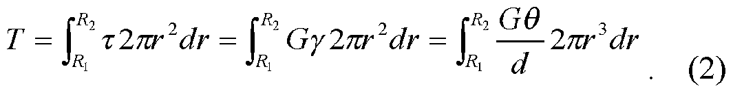
This simplifies to:
πθθ
T
2d (3)
Solving for the magnitude of the shear modulus, we find:
2Td
G* \= G
πθ^ -R ) (4)
[00131] The above expression for \G* \ is solved using experimental values of measured torque 7" and measured Θ given by the raw output of the rheometer software for a specific gap distance, d, and tool geometry of Ri and R2, and sinusoidal oscillation frequency ω. Figure 10 shows a schematic illustration of the upper and lower tools, and of the variables d, Ri, and R2.
[00132] Figure 11 shows a comparison of \G*\, the magnitude of the complex shear modulus, of a viscoelastic nanoemulsion measured using a 60 mm ABS annular parallel plate geometry (also referred to herein as an annular ring geometry) versus 25 mm Ti cone and plate rheometer tools. The strain sweep tests were both performed using an angular frequency of ω = 1 rad/s. The agreement in the linear region at small strains is within the run-to-run error in loading the rheometer with the material (i.e. average values are nearly the same and error bars overlap substantially). The points represent averages over three trials in which the tools are affixed to the rheometer, the sample is loaded, and the strain sweep test is performed. Error bars provide standard deviations over the three trials for each geometry separately.
[00133] A comparison between a standard 25 mm diameter Ti parallel plate (SPP) tool, manufactured by Rheometric Scientific, and a 5x annular parallel plate (5x APP) tool made by 3D printing in ABS material using our process, each of which has been used to measure the same concentrated viscoelastic emulsion sample, is shown in Figures 12, 13, 14A, and 14B. Inner and outer radii of the 5x APP are: Ri = 17.7 mm and i?2 = 21.7 mm. The strain reported for the SPP is the maximum strain in the gap, whereas the strain reported for the 5x APP is the average strain. Gaps between upper and lower tools for both 5x APP and SPP were set to be ~ 200 microns. Figure 12 shows the measured torque versus actuated angle. Figure 13 shows the stress versus strain. Figure 14A shows the storage modulus G' and loss modulus G" as a function of strain at a fixed frequency of ω = 1 rad/s, and Figure 14B shows G' and G" versus frequency at a fixed strain of γ ~ 0.01. Overall, the 5x APP does increase the measured torque level by about five times over the SPP for the same loaded sample volume. Good overlap of the functions τ(γ\ G'( ), and G"(y) are obtained in the measured strain sweeps obtained for the 3D printed 5x APP when compared to the manufacturer' s Ti SPP, especially in the linear regime at small strains where the results are theoretically expected to be the same. Also, the 3D printed 5x APP tool also gives effectively the same results for G'(<w) and G"(co) as the SPP when a frequency sweep has been performed in the linear viscoelastic response regime. This indicates that the phase angle between the applied sinusoidal strain and measured stress response is properly obtained over a wide range of frequencies in the linear viscoelastic regime by the 5x APP tool. This very good agreement of these experimental measurements indicates that the 3D printed 5x APP tool of ABS material performs comparably well to the manufacturer's titanium SPP for a real viscoelastic concentrated emulsion sample.
[00134] Determining \G* \ for an Annular Cone-and-Plate Geometry
[00135] Additional Definitions:
β = cone tapering angle measured between horizontal flat annular plate (lower tool) and annular cone (upper tool) (a small angle, typically).
[00136] The shear strain is defined as the ratio of material displacement along the plane of the plate divided by the distance d = fir at a particular radius r, relative to the rotary axis, perpendicular to the solid surface of the rheometer tool that is being displaced. Thus, for the aligned annular cone-and-plate geometry, the shear strain is independent of r: γ = Θτ1 βτ) = ΘΙβ where Θ is the maximum rotary angle produced by the rheometer' s motor at a specific angular frequency ω. Typically, Θ and β are reported in units of radians. Because the geometry is designed to have the upper tool as a cone, the shear strain field is uniform, provided that the upper annular cone tool is appropriately raised the correct distance above the lower annular plate tool. The gap setting where the upper tool touches the lower plate is set to be di = Ri tan β - ϋιβ using the rheometer' s micrometer. Having a uniform shear strain field can potentially be advantageous over the non-uniform field created by the annular parallel plate geometry. Typically,
 is designed to be much less than R∑ -
[00137] The shear stress, r, is defined as the ratio of the applied force divided by the cross sectional area displaced parallel to this applied force but perpendicular to the axis of the rheometer tools: r =F/A. The rheometer is equipped with a torque transducer; the average shear stress can be deduced from the torque using appropriate geometrical factors. The expression for the differential torque, dT, caused by the shear stress r acting on a differential annual ring, having width dr of the annular plate is: άΊ=2πΐ2άΐ τ. (5)
[00138] Integration to determine the total torque on the annular ring proceeds as follows, where we assume the linear Hookean approximation that τ=Ογ which should be valid in the limit of small applied shear strains:
 which simplifies to
2πΟΘ
which simplifies to
2πΟΘ
T =
3β (?)
Solving for the magnitude of the shear modulus, we find:

[00139] The above expression for |G* is solved using experimental values of measured torque Jand measured Θ given by the raw output of the rheometer software for a specific gap distance, d, cone angle, β, and tool geometry of Ri and Ri, and sinusoidal oscillation frequency ω. Figure 15 shows a schematic illustration of the upper and lower tools for the annular cone- and-plate rheometer geometry, and of the variables d, Ri, and R2.
[00140] Determining Storage Modulus and Loss Modulus from Periodic Annular Tool Measurements
[00141] Regardless of the choice of annular geometries, for a given angular oscillation amplitude 0(i.e. strain) at a frequency ω, the elastic storage modulus, G and the loss modulus, G", can be obtained from an additional output parameter of the rheometer software, known as the loss tangent: tan δ = G"IG'. This parameter can be found by analyzing the measured temporal waveforms of the torque J and angle Θ, and examining the phase lag c> between the zero crossings of these periodic functions (i.e., the torque is proportional to the stress and the angle Θ is proportional to the strain). A phase lag of zero corresponds to a perfectly elastic response for which G" (and therefore the loss tangent) approaches zero, whereas a phase lag of πΙ2 corresponds to a perfectly viscous response for which G' approaches zero (and therefore the loss tangent diverges). The complex shear modulus G* is defined as: G* = G' + iG"; consequently, its magnitude is: \G*\ = [(G'f + (G")2]1/2. Thus, since the ratio G"IG' and magnitude \G*\ are measured and known, the storage modulus and the loss modulus can be obtained from these as:
G' = \G*\/[\ + (G G' )2]1/2 and (9)
G" = [|G*|2 - (G' )2] (10) respectively.
[00142] In the material's linear response regime, the linear shear moduli \G*\, G', and G" are all independent of the strain γ. However, at larger strains beyond a yield strain or critical strain, these moduli can become strain-dependent, and they are often referred to as "nonlinear" moduli, even though technically they are well-defined only for very small strains where their values are independent of strain. These 3D printed custom-designed geometries, as well as other 3D printed standard geometries, can be used to measure both linear and non-linear moduli. These 3D printed geometries also can be used to measure steady-shear properties, such as effective viscosities, of soft materials. Thus, beyond measuring G'(co) and G"(o) in the linear regime, 3D printed geometries can also be used to measure non-linear G' and G", yield strain and yield stress, as well as steady-shear rate-dependent stress and effective viscosity.
[00143] Comparison of Performance: 3D Printed ABS vs. Titanium 25 mm Cone-and-Plate Geometries
[00144] We have loaded the same viscoelastic nanoemulsion sample into the 3D printed ABS cone-and-plate geometry and measured the shear moduli using a strain sweep test at ω = 1 rad/s. Figure 16 shows the average values of the magnitude of the complex shear modulus plotted as a function of strain. Within run-to-run error, there is very good agreement between the values of \G*\ using the 3D printed 25 mm cone-and-plate tools and the values of \G*\ obtained using the manufacturer's Ti 25 mm cone-and-plate tools. The cone angles on both ABS and Ti tools are 0.1 rad. The measurements were made at room temperature of 23 °C. Since the nanoemulsion is water-based, it does not interact with or substantially alter the ABS tools, which according to some embodiments are made of a hydrophobic polymer.
[00145] General Aspects of the Invention According to Some Embodiments
[00146] For the embodiments described herein, a wide variety of materials can be used for the 3D printed tool. The demonstration with ABS at room temperature in performing rheometric testing on an oil-in-water nanoemulsion sample is simply an example. A wide variety of 3D printing materials are available, and 3D printed rheometer tools suitable for rheometry applications can be printed from many of them. Examples of different filaments, which have different compositions, resistance to different solvents in materials, melting points, and different printed elastic moduli can be found from many manufacturers. Examples of available filaments suitable for use in the FlashForge 3D printer can be found online at
www.globalfsd.com. Some of these filaments are composites that contain fibers or particulates, in addition to polymer, so these can provide a natural roughness to the rheometer tools which can be desirable in some applications. Typically, a polymer-based filament material suitable for 3D printing rheometer tools is chosen to have an elastic shear modulus that is much greater than the magnitude of the complex viscoelastic shear modulus of the soft material to be tested in the rheometer. So, for ABS, which has an elastic modulus of about 1 GPa (giga-Pascal), the maximum elastic modulus of the soft material to be tested would ideally be less than about 10 MPa (mega-Pascal). Typically, a polymer-based filament material suitable for 3D printing rheometer tools is chosen to have a melting temperature {i.e. melting point) that is least about 20 °C larger than the maximum of the temperature range over which the rheometer tools will be used to measure the mechanical properties of the soft material in the rheometer.
[00147] By contrast to the manufacturer's titanium tools, any 3D printed ABS tools will melt if heated to sufficiently high temperatures. So, for doing rheology at high temperatures, 3D printed ABS tools are not recommended over metal tools that have a much higher melting temperature. Likewise, soft materials that have internal components, especially if present in a continuous phase, that act as solvents and can penetrate or partially dissolve the ABS tools, would not be recommended for long-term use with 3D printed ABS tools. Materials other than ABS {e.g. PLA poly-lactic acid) could be used as alternatives. Thus, the type of polymer or polymer composite material that could be used to print the tools is chosen to be compatible with the material components of the soft material to be measured in the rheometer.
[00148] Standard tests exist for determining whether or not undesirable wall slip of soft materials occurs at the surfaces of the 3D printed rheometer tools. In some cases for certain materials and certain 3D printed geometries, if wall slip is detected, it may be necessary to 3D print rheometer tools that have roughened surfaces, so that the roughness inhibits or prevents wall slip. Typically, the thicknesses of the connecting features {e.g., struts) on the upper and lower ABS tools are chosen to be at least one millimeter, so that deformation of the ABS tools by gravity and during loading and applied shear deformation during measurement is small. Thus, thicknesses in the design of the custom 3D printed ABS tools may be adjusted to account for the overall loading and rigidity of the final 3D printed ABS tools.
[00149] Rheometer tools printed using low-density plastics, such as ABS, are lightweight and have lower rotational inertia compared to metal tools (even titanium). This is
an advantage in two respects: (1) larger geometries can be 3D printed in plastic without disturbing the normal force transducer because they weigh less than metal tools having the same dimensions (3D printed tools can also be used for normal force measurements); and (2) plastic 3D printed tools have lower rotational inertias than metal tools having the same shape (and larger rotational inertias can lead to artifacts in rheological measurements at high excitation frequencies).
[00150] The tools according to some embodiments are printed in ABS using FlashForge Creator Pro running Sailfish v7.7 firmware, as shown in Figure 17. However, the embodiments of the invention are not limited to that printing material or that printer. GCode can be generated from .STL files made with Alibre Design™ Professional 2012 with Skeinforge (50) slicing software using default Replicator X ABS settings. Z-axis resolution is set to either 100 or 200 microns, 60% infill, 0 additional shells, extrusion speeds of 30-40 mm/s, and extrusion temperature of 230-235°C on a KaptoniS) tape covered aluminum build platform heated to 110°C. Self-adhesive Kapton® tape is positioned with dilute soap solution and air bubbles pressed out with smooth rubber blade squeegee to ensure flatness.
[00151] Data is recorded using a Rheometric Scientific Fluids Spectrometer Model RFS II, as shown in Figure 18, using Rheometric Scientific RSI Orchestrator Version V6.5.1 software for PC. The rheometer includes a displacement actuator and a stress transducer. Logarithmic dynamic strain sweep tests are performed at a frequency of 1.0 rad/s with 5 data points taken per decade at -23 °C ambient temperature. All measurements are recorded within minutes of sample loading to minimize effects of evaporation. No vapor trap is used. A vapor trap (e.g. an annular trough that holds water) can be readily incorporated into both printed tools.
[00152] A nanoemulsion having a droplet volume fraction /= 0.15 of droplets of 10 cSt trimethyl terminated poly-(dimethyl siloxane) (PDMS) oil in 10 mM aqueous sodium dodecyl sulfate (SDS) solution is prepared in a microfluidizer set to 30,000 psi and passed through the microfluidizer device five times. The nanoemulsion is then centrifuged at 12,000 rpm for 16 hours and the bottom 1/3 of plug is reserved as a viscoelastic fluid test sample in all rheometric measurements reported herein. The sample has been stirred and is highly uniform in droplet size and volume fraction, so it makes a suitable viscoelastic material for comparison testing. Figure 19 shows the viscoelastic nanoemulsion, contained in a glass jar.
[00153] Tool Assembly: Printing and Initial Preparation of Tool Components
[00154] Figure 20 shows a number of tool components that have been manufactured using 3D printing. The following describes the printing and preparation of the tool components. The 25 mm cone and plate tool will be used as an example of the process of assembling a rheometer tool from start to finish. The construction of other geometries can proceed similarly. The components of the upper and lower tools according to some embodiments are printed using 1.75 mm white ABS filament on FlashForge Creator Pro 3D printer. Any burrs or imperfections resulting from the printing process are cut or filed away, as illustrated in Figure 21.
[00155] According to some embodiments, printed plastic ABS geometries are designed to attach to pre-existing titanium tools of the RFS-II Rheometer. Figure 22 shows a 3/8"-16 threaded hole of a universal upper tool stem. The upper end of this tool is connected to the torque transducer. The screw thread can be connected to a 3D printed part. Figure 23 shows a lower cup tool that is connected to the rheometer motor.
[00156] A vinyl 3/8"- 16 bolt (or printed screw) is screwed into the universal titanium stem, as shown in Figure 24. The bolt or screw may be referred to herein as a "connector." Upper and lower tool components can be positioned and adjusted while in the rheometer under gentle normal force pressure to achieve a true alignment. The vinyl bolt is later solvent-welded to a mating receptacle on a customized 3D printed rheometer tool. The lower white ABS tool is secured to the lower Ti cup with three stainless steel #2-56 button socket cap screws and washers, as shown in Figure 25. Tapping of holes is unnecessary as the soft ABS materials allows the screw to self-tap creating a reusable thread. The ABS tool can be removed by unscrewing the cap screws
[00157] Figure 26 shows 3D printed components of the 25-mm cone and plate geometry and their assembly, (a) The upper tool components 3D printed in ABS are shown with sacrificial regions of part 1 intact, (b) Upper tool components are shown with sacrificial regions removed and before alignment and solvent welding, (c) The upper tool is shown after alignment and solvent welding, (d) Lower tool parts 3D printed in ABS are shown, (e) The lower tool components are shown before solvent welding, (f) The lower tool is shown after alignment and solvent welding, (g) Upper and lower tools are shown welded and mounted to rheometer hardware, ready to attach as indicated, (h) The cone tapering angle Θ = 0.1 rad is illustrated. According to some embodiments of the invention, the cone has a tapering angle that is between 0.01 radians and 0.7 radians. Numbers in Figure 26 indicate the order of assembly according
to some embodiments. However, the embodiments of the invention are not limited to this order of assembly. Scale bars in Figure 26 represent 25 mm.
[00158] Figures 27-29 provide schematic illustrations of three pieces that are combined to form a 25 mm upper cone tool. Figure 27 shows the cone piece, Figure 28 shows the platform/receptacle piece, and Figure 29 shows the threaded cap screw piece. The hexagonal receptacle receives the hexagonal head of hexagonal threaded screw cap. The Threaded Cap Screw Piece can be purchased at minimal cost from suppliers such as McMaster Carr and its threads may be superior to those that can be 3D printed using the FlashForge.
[00159] As shown in Figure 30, the half-cone according to some embodiments is printed on its side to increase resolution of the printed cone. Each half-cone maybe be printed with a sacrificial region that is removed after printing. As illustrated in Figure 31, the sacrificial region is removed (e.g., by filing) and two of the half cones are welded together to form a single complete cone piece.
[00160] The fused deposition additive manufacturing process employed by the maj ority of consumer grade 3D printers such as the FlashForge Creator Pro limits z-axis resolution to 100 microns. Printing an entire cone at once results in an unacceptable "stair step" result. Thus, conical tools are printed on their sides as two half-cones in order to take advantage of better 11 micron x-y plane resolution and thus maximize the dimensional fidelity of the print.
[00161] Excess material is filed away and carefully finished with fine grit sandpaper until prescribed dimensions are achieved. Two halves are joined together and affixed to remaining parts of tool assembly using acetone solvent welding. The resulting seam is smooth and barely visible. Figure 32 shows a complete upper cone tool with a triangle superimposed on the cone to demonstrate the accuracy of the method.
[00162] Figures 33-35 provide schematic illustrations of three pieces that are combined to form a lower plate tool. Figure 33 shows the 25 mm. diameter disk, Figure 34 shows the lower plate tool guide/alignment piece, and Figure 35 shows the lower plate tool mounting piece. The three pieces can be coaxially aligned and solvent welded to form the complete lower 25 mm plate tool. Separate piece construction and solvent welding eliminates the need for printing and removing complex supports. The lower plate tool can be used with both 25 mm cone and plate and parallel plate upper tool geometries.
[00163] The assembled ABS upper and lower tools are secured into the universal upper stem and lower cup, respectively, and held together with slight pressure. The alignment process is illustrated in Figure 36. Once the pieces of the upper and lower tools have been aligned, acetone can be introduced dropwise into seams to induce solvent welding, as shown in Figure 37. The vinyl bolt can be bonded to the ABS using quick setting epoxy.
[00164] Figure 38 shows a comparison of |G*| measured using ABS and Ti 25 mm cone and plate geometries. Figure 39 shows a comparison of |G*| measured using 25 mm Ti cone and plate, 25 mm ABS cone and plate, and ΙΟχΤ ABS annular parallel plate geometries.
[00165] Figure 40 illustrates half of a conical section for a 50 mm cone and plate tool. The fused deposition additive manufacturing process employed by the majority of consumer grade 3D printers such as the FlashForge Creator Pro limits z-axis resolution to 100 microns. Printing an entire cone at once results in an unacceptable "stair step" result. Thus, conical tools are printed on their sides as two half-cones in order to take advantage of the better 11 micron x-y plane resolution and thus maximize the dimensional fidelity of the print. The half cones are printed with excess material, as shown in Figure 41. The excess material is filed away and carefully finished with fine grit sandpaper until prescribed dimensions are achieved. The two halves are joined together and affixed to remaining parts of tool assembly using acetone solvent welding. As shown in Figure 42, the resulting seam is smooth and barely visible.
[00166] Figures 43-45 provide schematic illustrations of three pieces that are combined to form a 50 mm upper cone tool. Figure 43 shows the cone piece, Figure 44 shows the platform/receptacle piece, and Figure 45 shows the threaded cap screw piece. Figure 46 shows a complete upper cone tool with a triangle indicating the desired tool shape superimposed on the cone to demonstrate the accuracy of the method. Figure 47 shows a comparison of \G*\ measured using ABS and Ti 50 mm diameter cone and plate geometries.
[00167] Figures 48-50 provide schematic illustrations of three pieces that are combined to form a lower plate tool. Figure 48 shows the 50 mm diameter disk, Figure 49 shows the lower plate tool guide/alignment piece, and Figure 50 shows the lower plate tool mounting piece. The three pieces can be coaxially aligned and solvent welded to form the complete lower 50 mm plate tool. The lower plate tool can be used with both 50 mm cone and plate and parallel plate upper tool geometries.
[00168] Figure 51 shows 3D printed components of the 4.34 cm OD 5x torque annular parallel plate geometry and their assembly, (a) Upper tool components 3D printed in ABS are shown after removal of print supports, (b) Upper tool components are shown before alignment and epoxy adhesion, (c) Upper tool alignment after epoxy adhesion is depicted, (d) Lower tool parts 3D printed in ABS are shown, (e) Lower tool components are shown before alignment and solvent welding, (f) Lower tool after alignment and solvent welding is shown, (g) Upper and lower tools welded/epoxied and mounted to rheometer hardware, ready to attach as indicated, (h) Annular dimensions n = 1.77 cm, ri = 2.17 cm. Numbers indicate the order of assembly according to some embodiments. Scale bars represent 25 mm.
[00169] Figures 52 and 53 provide schematic illustrations of two pieces that are combined to form a 25 mm upper plate tool that can be used, for example, for a parallel plate geometry. Figure 52 shows the platform/receptacle piece, and Figure 53 shows the threaded cap screw piece. Figure 54 shows a complete upper plate tool. A rectangle of exact design dimension is superimposed on the upper plate tool demonstrating an accurate result. Figure 55 provides a comparison of \G*\ measured using ABS and Ti 25 mm parallel plate geometries.
[00170] Figures 56 and 57 provide schematic illustrations of two pieces that are combined to form a 50 mm upper plate tool that can be used, for example, for a parallel plate geometry. Figure 56 shows the platform/receptacle piece, and Figure 57 shows the threaded cap screw piece. Figure 58 shows a complete upper plate tool. A rectangle of exact design dimension is superimposed on the parallel plate tool demonstrating an accurate result. Figure 59 shows \G*\ measured using an ABS 50 mm parallel plate geometry.
[00171] Figures 60 and 61 provide schematic illustrations of two pieces that are combined to form a 60 mm upper annular ring tool. Figure 60 shows the platform/receptacle piece, and Figure 61 shows the threaded cap screw piece. Figure 62 shows a complete upper annular ring tool. A rectangle of exact design dimension is superimposed on the upper annular ring tool demonstrating an accurate result.
[00172] Figures 63-65 provide schematic illustrations of three pieces that are combined to form a lower annular ring tool. Figure 63 shows the 60 mm outer diameter ring, Figure 64 shows the lower annular ring tool guide/alignment piece, and Figure 65 shows the lower annular ring tool mounting piece. The three pieces can be coaxially aligned and solvent welded to form the complete lower 60 mm annular ring tool. Figure 66 shows an example of the 60
mm annular ring tool solvent welded in aligned position. To ensure precise and reproducible mating between the upper and lower tools, the parts are loosely affixed in their positions, and the rheometer upper head is carefully lowered until a normal force is registered. With all parts aligned, the separate pieces within the upper tool assembly and lower tool assembly are then acetone solvent welded permanently into position. The upper tool is not solvent welded to the lower tool, so both tools can easily be separated. This keeps both tools true. Figure 67 shows \G*\ measured using an ABS 60 mm annular ring geometry.
[00173] Figures 68-70 provide schematic illustrations of three pieces that are combined to form a 25 mm parallel plate tool with a rough surface. Figure 68 shows the rough surface piece, Figure 69 shows the platform/receptacle piece, and Figure 70 shows the threaded cap screw piece. The depth of the printed roughness features can typically be 100 microns or larger, corresponding to limitations of the layer thickness of a single polymer layer printed by the 3D printer. Here, the depth of the roughness feature is 0.40 mm (i.e. 400 microns). However, other depths may be implemented depending on the application and the printing material.
[00174] Figure 71 shows a complete upper parallel plate tool with a rough surface. Minor printing imperfections on roughened surfaces are sanded flat, enabling the gap distance between upper and lower tool to be adjusted properly using a micrometer prior to loading a material and making a rheological measurement.
[00175] Figures 72-75 provide schematic illustrations of four pieces that are combined to form a 25 mm diameter lower parallel plate tool with a rough surface. Figure 72 shows the 25 mm diameter rough surface piece, Figure 73 shows the 25 mm diameter disk, Figure 74 shows the lower parallel plate tool guide/alignment piece, and Figure 75 shows the lower plate tool mounting piece. The four pieces can be coaxially aligned and solvent welded to form the complete lower 25 mm parallel plate tool with a rough surface. Separate piece construction and solvent welding eliminates the need for printing and removing complex supports. Figure 76 shows the final upper and lower parallel plate tools with rough surfaces. The rough surfaces may be referred to as "grated" surfaces, indicating that the surfaces are patterned and uneven. The grated surfaces are not limited to the patterns shown herein; other patterns may be used to prevent slippage of soft materials where they make contact at the surfaces of the tools.
[00176] Figures 77-79 provide schematic illustrations of three pieces that are combined to form a 50 mm parallel plate tool with a rough surface. Figure 77 shows the rough surface
piece, Figure 78 shows the platform/receptacle piece, and Figure 79 shows the threaded cap screw piece. Figure 80 shows a complete upper parallel plate tool with a rough surface.
[00177] Figures 81-84 provide schematic illustrations of four pieces that are combined to form a 50 mm diameter lower parallel plate tool with a rough surface. Figure 81 shows the 50 mm diameter rough surface piece, Figure 82 shows the 50 mm diameter disk, Figure 83 shows the lower parallel plate tool guide/alignment piece, and Figure 84 shows the lower plate tool mounting piece. The four pieces can be coaxially aligned and solvent welded to form the complete lower 50 mm parallel plate tool with a rough surface. Separate piece construction and solvent welding eliminates the need for printing and removing complex supports.
[00178] REFERENCE
[00179] [1] Bikos, Dimitri A., and Thomas G. Mason. "Customizable tool geometries by additive manufacturing for mechanical rheometry of soft matter." Journal of Rheology 60.6 (2016): 1257-1267.
[00180] The embodiments illustrated and discussed in this specification are intended only to teach those skilled in the art how to make and use the invention. In describing embodiments of the invention, specific terminology is employed for the sake of clarity. However, the invention is not intended to be limited to the specific terminology so selected. The above- described embodiments of the invention may be modified or varied, without departing from the invention, as appreciated by those skilled in the art in light of the above teachings. It is therefore to be understood that, within the scope of the claims and their equivalents, the invention may be practiced otherwise than as specifically described.
Claims
1. A method of producing, using a 3-D printer, a tool for use in a rotary rheometer having an axis of rotation, the method comprising:
providing a connector configured to connect to a first portion of said rotary rheometer; forming, in said 3-D printer, a first receptacle piece having a first side forming a receptacle for receiving said connector, and a second side comprising a flat surface;
providing a second receptacle piece having a first side comprising a surface for contacting a material to be measured, and a second side forming a receptacle for receiving a second portion of said rotary rheometer;
coaxially aligning said connector, said first receptacle piece, and said second receptacle piece with said axis of rotation of said rotary rheometer; and
welding said connector to said first receptacle piece,
wherein said first receptacle piece and said second receptacle piece each have a circumference, wherein the circumference of the first receptacle piece is substantially equal to and aligned with the circumference of the second receptacle piece, and
wherein a polar alignment error of said first and second receptacle pieces is less than 0.01 radians.
2. The method of claim 1, wherein said connector and said first receptacle piece form a first tool portion.
3. The method of claim 1 or 2, wherein providing said second receptacle piece comprises: forming, in said 3-D printer, said second receptacle piece.
4. The method of claim 1 or 2, wherein providing said second receptacle piece comprises: forming, in said 3-D printer, a lower contact piece, the lower contact piece having a first side comprising a surface for contacting a material to be measured, and a second side comprising a flat surface;
forming, in said 3-D printer, a third receptacle piece having a first side forming a receptacle for receiving said lower contact piece, and a second side comprising a flat surface; forming, in said 3-D printer, a fourth receptacle piece having a first side comprising a flat surface for adhearing to said flat surface of said third receptacle piece, and a second side forming a receptacle for receiving said second portion of said rotary rheometer;
coaxially aligning an upper tool portion, said lower contact piece, said third receptacle piece, and said fourth receptacle piece with said axis of rotation of said rotary rheometer; and welding said lower contact piece, said third receptacle piece, and said fourth receptacle piece to form said second receptacle piece,
wherein said upper tool portion and said lower contact piece each have a circumference, wherein the circumference of the lower contact piece is substantially equal to and aligned with the circumference of the upper tool portion, and
wherein a polar alignment error of said upper tool portion and said lower contact piece is less than 0.01 radians.
5. The method of claim 4, wherein said first side of said lower contact piece comprising a surface for contacting a material to be measured comprises a raised annuli.
6. The method of claim 4, wherein said surface of said first side of said lower contact piece is a grated surface.
7. The method as in any one of claims 1-6, further comprising:
forming, in said 3-D printer, first and second halves of a cone piece, each of said first and second halves comprising a sacrificial portion formed on a print bed of said 3-D printer, and a circular portion extending up from the sacrificial portion;
removing said sacrificial portion of said first and second halves of said cone piece; welding said first and second halves of said cone piece to form said cone piece;
aligning said connector, said first receptacle piece, and said cone piece in said rotary rheometer; and
welding said first receptacle piece to said cone piece,
wherein said cone piece has a tapering angle between 0.01 radians and 0.7 radians.
8. The method as in any one of claims 1-7, wherein said flat surface of said first receptacle piece forms a ring having an inner circumference and an outer circumference, and
wherein the outer circumference of the first receptacle piece is substantially equal to and aligned with the circumference of the second receptacle piece.
9. The method as in any one of claims 1-7, further comprising:
forming, in said 3-D printer, a rough surface piece having a first side comprising a flat surface for contacting the second side of the first receptacle piece, and a second side having a grated surface;
aligning said connector, said first receptacle piece, and said rough surface piece in said rotary rheometer; and
welding said first receptacle piece to said rough surface piece.
10. A tool for use in a rotary rheometer, said tool produced according the method as in any one of claims 1-9.
11. A rotary rheometer, comprising:
a displacement actuator;
a stress transducer;
a first annular ring tool portion having a connector configured to connect to one of said displacement actuator and said stress transducer, and an annular ring portion opposite said connector; and
a second annular ring tool portion in connection with said other one of said displacement actuator and said stress transducer,
wherein said annular ring portion of said first annular ring tool portion has an inner circumference and an outer circumference, and wherein said second annular ring tool portion has a circumference that is substantially equal to and aligned with said outer circumference.
12. A rotary rheometer according to claim 11, wherein said inner circumference is about 54 mm.
13. A rotary rheometer according to one of claims 11 and 12, wherein said outer circumference is about 60 mm.
Applications Claiming Priority (2)
| Application Number | Priority Date | Filing Date | Title |
|---|---|---|---|
| US201662277378P | 2016-01-11 | 2016-01-11 | |
| US62/277,378 | 2016-01-11 |
Publications (1)
| Publication Number | Publication Date |
|---|---|
| WO2017123639A1 true WO2017123639A1 (en) | 2017-07-20 |
Family
ID=59311836
Family Applications (1)
| Application Number | Title | Priority Date | Filing Date |
|---|---|---|---|
| PCT/US2017/013027 WO2017123639A1 (en) | 2016-01-11 | 2017-01-11 | Customized rheometer tools by three dimensional printing |
Country Status (1)
| Country | Link |
|---|---|
| WO (1) | WO2017123639A1 (en) |
Cited By (3)
| Publication number | Priority date | Publication date | Assignee | Title |
|---|---|---|---|---|
| WO2019059401A1 (en) * | 2017-09-25 | 2019-03-28 | 三菱重工業株式会社 | Three-dimensional additively-formed product and three-dimensional additive forming method |
| JP2019090066A (en) * | 2017-11-10 | 2019-06-13 | 三菱重工業株式会社 | Product and method of three-dimensional lamination molding |
| US11698330B2 (en) | 2019-10-15 | 2023-07-11 | Massachusetts Institute Of Technology | Systems, devices, and methods for rheological measurement of yield stress fluids using fractal-like fixtures |
Citations (5)
| Publication number | Priority date | Publication date | Assignee | Title |
|---|---|---|---|---|
| US20050199043A1 (en) * | 2004-03-11 | 2005-09-15 | Nigel Doe | Rotary rheometer magnetic bearing |
| US20140086704A1 (en) * | 2011-06-02 | 2014-03-27 | A. Raymond Et Cie | Fasteners manufactured by three-dimensional printing |
| US20140319716A1 (en) * | 2007-03-07 | 2014-10-30 | Stratasys Ltd. | Rapid production apparatus with production orientation determination |
| US20150251356A1 (en) * | 2014-03-10 | 2015-09-10 | Stratasys, Inc. | Method for Printing Three-Dimensional Parts with Part Strain Orientation |
| KR20150120643A (en) * | 2014-04-18 | 2015-10-28 | 쓰리디토시스 주식회사 | 3d printing system using block type structure combined with fdm technology and this hybrid data generation method for 3d printing |
-
2017
- 2017-01-11 WO PCT/US2017/013027 patent/WO2017123639A1/en active Application Filing
Patent Citations (5)
| Publication number | Priority date | Publication date | Assignee | Title |
|---|---|---|---|---|
| US20050199043A1 (en) * | 2004-03-11 | 2005-09-15 | Nigel Doe | Rotary rheometer magnetic bearing |
| US20140319716A1 (en) * | 2007-03-07 | 2014-10-30 | Stratasys Ltd. | Rapid production apparatus with production orientation determination |
| US20140086704A1 (en) * | 2011-06-02 | 2014-03-27 | A. Raymond Et Cie | Fasteners manufactured by three-dimensional printing |
| US20150251356A1 (en) * | 2014-03-10 | 2015-09-10 | Stratasys, Inc. | Method for Printing Three-Dimensional Parts with Part Strain Orientation |
| KR20150120643A (en) * | 2014-04-18 | 2015-10-28 | 쓰리디토시스 주식회사 | 3d printing system using block type structure combined with fdm technology and this hybrid data generation method for 3d printing |
Cited By (3)
| Publication number | Priority date | Publication date | Assignee | Title |
|---|---|---|---|---|
| WO2019059401A1 (en) * | 2017-09-25 | 2019-03-28 | 三菱重工業株式会社 | Three-dimensional additively-formed product and three-dimensional additive forming method |
| JP2019090066A (en) * | 2017-11-10 | 2019-06-13 | 三菱重工業株式会社 | Product and method of three-dimensional lamination molding |
| US11698330B2 (en) | 2019-10-15 | 2023-07-11 | Massachusetts Institute Of Technology | Systems, devices, and methods for rheological measurement of yield stress fluids using fractal-like fixtures |
Similar Documents
| Publication | Publication Date | Title |
|---|---|---|
| WO2017123639A1 (en) | Customized rheometer tools by three dimensional printing | |
| Malyshev et al. | The strength of adhesive joints using the theory of cracks | |
| US7526941B2 (en) | Rheometer torque calibration fixture | |
| JP4953309B2 (en) | Orthogonal rheometer | |
| Jing et al. | A runout measuring method using modeling and simulation cutting force in micro end-milling | |
| JPH0660870B2 (en) | Viscoelasticity measuring device and measuring method | |
| JPH05332911A (en) | Apparatus for measuring rheological characteristics of viscoelastic test pieace and method therefor | |
| US7536924B2 (en) | Flexure-based dynamometer for determining cutting force | |
| Zhu et al. | Ultrasonic elliptical vibration texturing of the rake face of carbide cutting tools for adhesion reduction | |
| JP6547784B2 (en) | Interface strength evaluation method for fiber reinforced composite materials | |
| Li et al. | A batch-mode micromachining process for spherical structures | |
| Viswanath et al. | High resolution micro ultrasonic machining for trimming 3D microstructures | |
| US11698330B2 (en) | Systems, devices, and methods for rheological measurement of yield stress fluids using fractal-like fixtures | |
| JP2002214123A (en) | Interface adhesion strength measuring method and device of sprayed coating | |
| JP6105579B2 (en) | Clamp device for balance testing machine | |
| US20170307491A1 (en) | Strength testing of a flatwise material coupon | |
| JP6089148B2 (en) | Orthogonal super position rheometer | |
| US20070180938A1 (en) | Method and device for determining at least one dynamic property of a deformable solid or fluid material | |
| JP2016518613A5 (en) | ||
| Kamplade et al. | Examination of the material removal of unreinforced, thermoplastic polymers by scratch tests | |
| Maierhofer et al. | Thoughts on automatic impulse hammer parameters and sensor fixation methods | |
| CN106840976A (en) | One kind is based on the improved interface sliding parameter measuring apparatus of rheometer and method | |
| CN109669046A (en) | Detachment device for accelerometer head and the method for splitting using it | |
| Jemy et al. | Fabrication of Chemotaxis Microfluidic Device Mould Using Digital Light Processing 3D Printing Method | |
| CFRP | An Experimental Investigation of Tool Wear When Conventionally Drilling CFRP |
Legal Events
| Date | Code | Title | Description |
|---|---|---|---|
| 121 | Ep: the epo has been informed by wipo that ep was designated in this application |
Ref document number: 17738862 Country of ref document: EP Kind code of ref document: A1 |
|
| NENP | Non-entry into the national phase |
Ref country code: DE |
|
| 122 | Ep: pct application non-entry in european phase |
Ref document number: 17738862 Country of ref document: EP Kind code of ref document: A1 |