WO2017122807A1 - Vehicular air-conditioning device - Google Patents
Vehicular air-conditioning device Download PDFInfo
- Publication number
- WO2017122807A1 WO2017122807A1 PCT/JP2017/001096 JP2017001096W WO2017122807A1 WO 2017122807 A1 WO2017122807 A1 WO 2017122807A1 JP 2017001096 W JP2017001096 W JP 2017001096W WO 2017122807 A1 WO2017122807 A1 WO 2017122807A1
- Authority
- WO
- WIPO (PCT)
- Prior art keywords
- lower case
- door
- air
- vehicle
- rotation shaft
- Prior art date
Links
Images


Classifications
-
- B—PERFORMING OPERATIONS; TRANSPORTING
- B60—VEHICLES IN GENERAL
- B60H—ARRANGEMENTS OF HEATING, COOLING, VENTILATING OR OTHER AIR-TREATING DEVICES SPECIALLY ADAPTED FOR PASSENGER OR GOODS SPACES OF VEHICLES
- B60H1/00—Heating, cooling or ventilating [HVAC] devices
Definitions
- the present invention relates to an air conditioner for a vehicle, and more particularly to an air conditioner for a vehicle that incorporates a heat exchanger for cooling and a heat exchanger for heating and can be stacked and assembled.
- Patent Document 1 As a conventionally known laminated vehicle air conditioner, for example, there is one described in Patent Document 1. This includes a case that is divided into at least three parts, ie, upper, middle, and lower in the vehicle vertical direction on a substantially parallel dividing plane, and these cases are stacked in the vehicle vertical direction to form one case. A technical idea of a vehicle air conditioner is disclosed.
- a cooling heat exchanger and a heating heat exchanger are accommodated, and an inside / outside air switching door, a blow mode switching door, and an air mixing door that form an air passage that passes or bypasses them.
- the technical idea of a vehicle air conditioner is disclosed in which air passage opening / closing doors such as these are provided and the rotation shafts of these air passage opening / closing doors are rotatably sandwiched between the end faces of two cases out of three cases. Has been.
- the vehicle air conditioner can be assembled by a simple operation in which the air conditioner and the airway opening / closing door are sequentially stacked in one direction from the bottom to the top. Thereby, reduction of the assembly man-hour of a vehicle air conditioner is realizable.
- an object of the present invention is to provide a vehicle air conditioner that has few restrictions on the shape and layout of the case and door and has good assemblability.
- a vehicle air conditioner according to an aspect of the present invention.
- -A lower case disposed below the vehicle in the vertical direction;
- An upper case stacked above the lower case along the vehicle vertical direction to form an internal space with the lower case;
- a door having a rotation shaft, rotatably disposed in the internal space and controlling an airflow flowing through the internal space, and one or both ends of the rotation shaft accommodated in the internal space; , It is characterized by providing.
- the door includes one or two or more of an inside / outside air switching door, an air mix door, and a mode door for controlling the air flow in the vehicle air conditioner.
- both ends of the rotation shaft of the door cannot be held between the case end surfaces, and at least one end is accommodated in the internal space of the case. Therefore, the position (height) of the door and the position (height) of the case end surface are They may not be the same, and there are advantages such as an increased degree of freedom in the shape of the case, easy manufacture of the case, and improved accuracy of the entire apparatus.
- the vehicle air conditioner of the present invention is further provided on the inner space side of the lower case, and the rotating shaft accommodated in the inner space when the door is disposed in the inner space. It is good also as providing the rotation axis
- vehicle air conditioner according to the present invention is further provided in the lower case on the side of the inner space, and is configured to rotate at one end or both ends of the rotating shaft accommodated in the inner space. It is good also as providing a dynamic shaft support part.
- At least one end of the rotation shaft is placed on the rotation shaft support portion during the assembly of the apparatus, so that the assembling property in the assembly from the upper side is improved, and further, the rotation after the assembly is also rotated.
- the whole structure is simplified and a reduction in manufacturing cost is expected.
- the vehicle air conditioner according to the present invention further includes a lever that is fitted to the rotation shaft and transmits a driving force from the outside of the lower case and / or the upper case to the rotation shaft. May be a feature.
- the vehicle air conditioner of the present invention is further fitted from the outside of the rotating shaft and the lower case and / or the upper case to restrict movement of the door in the axial direction of the rotating shaft.
- a stopper may be provided.
- the vehicle air conditioner of the present invention there is no restriction on the shape or layout of the case or the door, such as the case where the end of the case supporting the rotation shaft does not need to be configured at the same position (height) as the rotation shaft. It is possible to provide a vehicle air conditioner that has few and good assemblability.
- 1 is an exploded view of a first embodiment of the present invention. It is a typical sectional view of a 1st embodiment of the present invention. It is a typical sectional view of the rotation axis support structure of a 1st embodiment of the present invention. It is a fragmentary perspective view of the rotating shaft support structure of the 1st Embodiment of this invention. It is a fragmentary perspective view of the rotating shaft support structure of the 1st Embodiment of this invention. It is a fragmentary perspective view of the rotating shaft support structure of the 1st Embodiment of this invention. It is a fragmentary perspective view of the rotating shaft support structure of the 1st Embodiment of this invention. It is typical sectional drawing of the rotating shaft support structure of the 2nd Embodiment of this invention.
- FIG. 1 is a perspective view of a vehicle air conditioner according to a first embodiment of the present invention
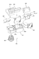
- FIG. 2 is an exploded view
- FIG. 3 is a view of the vehicle air conditioner 1 of FIG. It is typical sectional drawing.
- the vehicle air conditioner 1 is mounted in front of the interior of a vehicle, and is roughly divided into a blower mechanism (left side in FIG. 1) that sends an air flow, and a temperature condition that cools and heats the air flow. 1 and a part of the lower case 10, a part of the first upper case 20, a blower 80, an inside / outside air switching door 90, etc. Part, first upper case 20, second upper case 30, cooling heat exchanger 40, heating heat exchanger 50, air mix door 60, mode door 70 (also referred to as air distribution door), etc. Configure the mechanism.
- FIG. 3 shows a schematic cross-sectional view on the temperature conditioning mechanism side.
- the inside / outside air switching door 90, the air mix door 60, and the mode door 70 may be collectively referred to as an air passage switching door or simply a door.
- the lower case 10 has a box-like shape that is disposed below the vehicle in the vertical direction, has a space inside, and is open at the top.
- the plurality of upper cases are stacked one layer above the lower case 10 along the vertical direction of the vehicle, the lower part is opened, and the upper case is combined with the lower case 10 to form an internal space.
- a case 20 and a second upper case 30 are provided.
- the blower mechanism side has, in the first upper case 20, an outside air introduction port (not shown) for guiding air outside the vehicle and an inside air introduction port 20a for guiding the air inside the vehicle.
- the temperature conditioning mechanism side includes a first upper case 20, a defrost opening 21, a second upper case 30, and a vent opening 31 for blowing air toward the driver's upper body. And a foot opening 32 for blowing air to the feet.
- the inside / outside air switching door 90 adjusts the ratio of the air taken into the vehicle air conditioner 1 between the outside air introduced from the outside air inlet (not shown) and the inside air introduced from the inside air inlet 20a.
- the cross section is shown as a rotary door having an arc-shaped outer peripheral portion, fan-shaped portions at both ends thereof, and a rotating shaft 91 penetrating through the center portions of the fan-shaped portions on both sides. Provided upstream. The support structure of the rotation shaft 91 of the inside / outside air switching door 90 will be described later.
- the blower 80 guides the air introduced from the outside air inlet (not shown) and / or the inside air inlet 20a to the cooling heat exchanger 40.
- the blower 80 includes an impeller and a motor that rotates the impeller, and is mounted on the blower mechanism side of the lower case 10.
- the cooling heat exchanger 40 is disposed in an internal space formed by the lower case 10 and the first upper case 20, and is connected to a known refrigeration cycle. Air that flows through the internal space is circulated. It is possible to cool.
- the heating heat exchanger 50 is an internal space formed by the lower case 10 and the second upper case 30 and is arranged behind the cooling heat exchanger 40 in the front-rear direction of the vehicle. It is connected, and it is possible to heat all or part of the air that has flowed through the cooling heat exchanger 40.
- the air mix door 60 uses an airflow (cold air) that bypasses the heating heat exchanger 50 and an airflow that passes through the heating heat exchanger 50 (air) (air) that passes through the cooling heat exchanger 40 and is sent to the mode door 70.
- the ratio with warm air is adjusted.
- it is shown as a cantilever door having a rotating shaft 61 and a closing portion 62 extending from the rotating shaft 61, and between the cooling heat exchanger 40 and the heating heat exchanger 50. Is provided.
- a support structure for the rotation shaft 61 of the air mix door 60 will be described later.
- the mode door 70 distributes the conditioned air to a desired outlet for the air conditioned by the vehicle air conditioner 1.
- the cross section is shown as a rotary door including an outer peripheral portion having an arc shape, fan-shaped portions at both ends thereof, and a rotating shaft 71 penetrating through the center portions of the fan-shaped portions on both sides, and a defrost opening 21, the vent opening 31 and the foot opening 32 are provided in the vicinity, and an opening for ventilation is appropriately provided on the outer peripheral portion.
- a support structure for the rotation shaft 71 of the mode door 70 will be described later.
- FIG. 4 is a schematic cross-sectional view of the rotating shaft support structure of the first embodiment of the vehicle air conditioner according to the present invention, and a cut surface at a plane orthogonal to the plane A shown in FIG. Is. 5, 6 and 7 are partial perspective views of the rotating shaft support structure of the first embodiment of the vehicle air conditioner of the present invention.
- air mix door mounting holes 63 a and 63 b and mode door mounting holes 73 a and 73 b are provided on the left and right side surfaces of the right portion (temperature conditioning mechanism side) of the lower case 10.
- the rotation shaft 61 of the air mix door 60 is formed to be shorter than the left and right inner widths of the lower case 10, and both ends of the rotation shaft 61 are installed in the internal space of the vehicle air conditioner.
- the lower case 10 is provided with rotating shaft placement portions 13 a and 13 b that protrude inward of the lower case 10.
- FIG. 5 is a partial perspective view of the rotating shaft support structure of the first embodiment of the present invention, showing a part of the inner wall surface of the lower case 10 from the inner space side of the vehicle air conditioner.
- the rotating shaft mounting portion 13a (13b) protrudes from the air mix door mounting hole 63a (63b) to the inside of the lower case 10 and has a concave upper surface so that the rotating shaft 61 can be stably mounted. It is formed in a cross-sectional shape.
- one end (right end) of the rotating shaft 61 is stepped, and the tip portion 61a has a substantially cross-shaped cross section.
- the tip portion 61a has two steps. Are inserted into a stopper 65 having a substantially cross-shaped hole 65a at the end of the narrow diameter side.
- the other end (left end) of the rotating shaft 61 is stepped, the tip portion 61b is formed in a substantially cross shape, and the tip portion 61b has two steps.
- a thick cylinder formed from a cylinder has a flat plate portion 66a and is inserted into a lever 66 having a substantially cross-shaped hole 66b at the end of the narrow diameter side.
- the rotation shaft 61 can be rotated integrally by fitting the both ends of the rotation shaft 61 with the substantially cross-shaped portion of the stopper 65 and the lever 66.
- the end on the narrow side is freely fitted in a well-known manner while maintaining airtightness with the air mix door mounting hole 63a of the lower case 10, and the axial movement of the rotary shaft 61 is restricted. is doing.
- the end portion of the cylindrical portion of the lever 66 is freely fitted to the air mix door mounting hole 63b of the lower case 10 in a well-known manner while maintaining airtightness.
- a known mechanism such as a method using a link (Japanese Patent Application Laid-Open No. 2004-189110) may be used in addition to providing a substantially cross-shaped portion.
- rotation shaft placement portions 13a and 13b are provided at positions away from the rotation shaft 61 when the assembly is completed.
- the rotation shaft 71 of the mode door 70 is provided with a stopper 75, lever, and mode door mounting holes 73a, 73b on the right side portion of the lower case 10 (temperature conditioning mechanism side).
- the inside / outside air switching door 90 is supported by a similar structure using the inside / outside air switching door mounting holes 93a, 93b on the left side portion (air blowing mechanism side) of the lower case 10, and a stopper and lever (not shown) are used. It is attached with the same structure using.
- FIG. 3 the airflow is indicated by arrows.
- the outside air and / or the inside air introduced into the space formed by the lower case 10, the first upper case 20, and the second upper case 30 from the inside / outside air switching door 90 is directed toward the cooling heat exchanger 40 by the blower 80. And circulated.
- the airflow that has passed through the cooling heat exchanger 40 is guided by the air mix door 60 in the direction of the heating heat exchanger 50 or in the direction not passing through the heating heat exchanger 50 (an alternative route).
- the airflow in both directions can be blown by appropriately changing the mixing ratio.
- the turning position of the air mix door 60 can be performed by turning the turning shaft 61 by turning the flat plate portion 66a of the lever 66 by a drive mechanism (not shown).
- the airflow passing through the heating heat exchanger 50 is heated by the heating heat exchanger 50, becomes warm air, and reaches a space (air mix space) where the mode door 70 is disposed.
- the airflow that bypasses the heat exchanger 50 for heating reaches the space (air mix space) in which the mode door 70 is arranged without being heated by the heat exchanger 50 for heating, with the cold air.
- both hot air and cold air are present, they merge in the space (air mix space) in which the mode door 70 is disposed, and the temperatures are harmonized.
- the airflow flows out to a plurality of openings of the defrost opening 21, the vent opening 31, the foot opening 32, or a combination thereof depending on the rotational position of the mode door 70.
- the turning position of the mode door 70 can be performed by turning the turning shaft 71 by turning the flat plate portion of the lever with a drive mechanism (not shown).
- the lower case 10 is placed on a horizontal plane with the opening facing up.
- the cooling heat exchanger 40 is placed on the lower case 10 in an upright position so that the airflow direction is the vehicle front-rear direction. Further, the heat exchanger 50 for heating is similarly placed in a standing position.
- both ends of the rotation shaft 61 of the air mix door 60 are mounted on the rotation shaft mounting portions 13 a and 13 b of the lower case 10.
- the stopper 65 is moved closer to the left side of the lower case 10 and the lever 66 is moved closer to the right side of the lower case 10, so that both end portions 61 a and 61 b of the rotating shaft 61 are connected to the hole 65 a of the stopper 65 and the hole 66 a of the lever 66. Further, the cylindrical portions of the stopper 65 and the lever 66 on the narrow diameter side are fitted into the mounting holes 63a and 63b of the lower case 10 so as to be rotatable.
- the mode door 70 is assembled to the lower case 10 in the same manner as the air mix door 60.
- the second upper case 30 is moved from above and brought into close contact with the lower case 10.
- the fitting part P2 (refer FIG. 3) of the lower case 10 and the 2nd upper case 30, it is desirable to take a conventionally known airtight countermeasure.
- the inside / outside air switching door 90 is assembled to the lower case 10 in the same manner as the air mix door 60 on the air blowing mechanism side.
- the first upper case 20 is moved from above and brought into close contact with the lower case 10 to firmly fix the cooling heat exchanger 40. It is also desirable to take a conventionally known airtight countermeasure for the fitting portion P1 between the lower case 10 and the first upper case 20 and the fitting portion P3 between the first upper case 20 and the second upper case 30.
- the main elements of the vehicle air conditioner can be assembled sequentially from above, which is extremely effective for improving work efficiency and automation (robotization).
- the step of inserting the stopper and the lever may be performed from the left-right direction after the first upper case and the second upper case are assembled.
- rotation shaft placement portions 13a and 13b for temporarily supporting the rotation shaft 61 of the air mix door 60 during assembly are provided, and the rotation shaft placement portions 13a and 13b are rotated after the assembly is completed.
- the rotating shaft 61 is held in such a state that one or both rotating shaft mounting portions can be rotated with a well-known bearing function in this portion even after the assembly is completed. It is good also as a rotating shaft support part.
- the rotation shaft is placed on the rotation shaft support portion during the assembly of the apparatus, the assemblability in the assembly from above becomes better, and further, the support of the rotation shaft can be supported after the assembly.
- the overall structure may be simplified and the manufacturing cost may be reduced.
- the door shape also made the air mix door 60 cantilever and the mode door 70 and the inside / outside air switching door 90 a rotary type, it is not limited to this, butterfly type which provided the obstruction
- the second upper case 30 and the first upper case 20 are assembled in the order of assembling order, but the order may be reversed from the situation such as pre-assembly of other components. In some cases, efficiency can be increased.
- the air mix door 60, the mode door 70, or the inside / outside air switching door 90 is sequentially assembled, it may be pre-assembled in the lower case 10 in advance. The advantage that the final assembly is simplified can also be considered.
- FIG. 8 is a schematic cross-sectional view of the rotating shaft support structure in this embodiment of the vehicle air conditioner of the present invention.
- the air mix door 160 will be described, but it can also be applied to other mode doors and inside / outside air switching doors.
- the rotation shaft 161 of the air mix door 160 is formed shorter than the left and right inner widths of the lower case 110, and both ends of the rotation shaft 161 are installed in the internal space of the vehicle air conditioner. Become. Further, the rotation shaft 161 is mounted on rotation shaft mounting portions 113 a and 113 b provided inside the lower case 110. However, the position of the rotating shaft 161 is not a mounting hole provided in the lower case 110, but bearing portions 169a and 169b (split bearings) that are vertically divided into fitting portions between the lower case 110 and the second upper case 130. (Also called). Since other structures are the same as those of the first embodiment, description thereof is omitted. *
- both ends of the rotation shaft 161 of the air mix door 160 are mounted on the rotation shaft mounting portions 113 a and 113 b of the lower case 110.
- the stopper 165 is moved closer to the left side of the lower case 110, the lever 166 is moved closer to the right side of the lower case 110, both ends of the rotating shaft 161 are inserted into the stopper 165 and the lever 166, and the stopper 165 and lever 166 are moved further.
- the lower side of the cylindrical portion on the narrow diameter side is rotatably mounted on the bearing portions 169a and 169b on the lower case 110 side. In this state, the movement of the rotating shaft 161 in the axial direction is restricted by the stopper 165.
- the rotation shaft 161 is separated from the rotation shaft mounting portions 113a and 113b, and does not come into contact with the rotation shaft mounting portions 113a and 113b.
- the rotation shaft 161 of the air mix door 160 is provided with the bearing portions 169a and 169b that are vertically divided into the fitting portions between the lower case 110 and the second upper case 130 via the stopper 165 and the lever 166. Is supported rotatably.
- FIG. 9 is a schematic view of this embodiment of the vehicle air conditioner of the present invention.
- the air mix door 260 will be described, but it can also be applied to other mode doors and inside / outside air switching doors.
- the structure of the lower case 210 is such that one side (right side) wall surface is high and the other side (left side) wall surface is low.
- the rotation shaft 261 of the air mix door 260 is formed shorter than the left and right inner widths of the lower case 210, and both ends of the rotation shaft 261 are installed in the internal space of the vehicle air conditioner.
- the rotation shaft placement portions 213a and 213b are provided inside the lower case 210, and the rotation shaft 261 is placed during the assembly.
- one end (right end) is inserted into the lever 266 inserted into the mounting hole 263 provided in the lower case 210, and the other end (left end) is the lower case 210 and the second upper case 230. It is inserted in the stopper 265 mounted on the bearing part 269 provided in the fitting part. That is, the first embodiment and the second embodiment are mixed.
- FIG. 10 is a schematic diagram of this embodiment of the vehicle air conditioner of the present invention.
- the air mix door 360 will be described, but it can also be applied to other mode doors and inside / outside air switching doors.
- the rotation shaft 316 has such a length that only one end (right end) exists inside the lower case 310 and the other end (left end) extends to the outside of the lower case 310.
- the structure of the lower case 310 is such that the one side (right side) wall surface is high and the other side (left side) wall surface is low, and the rotation shaft placing portion 313 is provided only on one side (right side) inside the lower case 310, On the other side, a bearing portion 369 is provided between the lower case 310 and the second upper case 330.
- one end is inserted into the lever 366 inserted into the mounting hole 363 provided in the lower case 310.
- the other end (left end) is placed on a lower portion of a bearing portion 369 (split bearing) provided in a fitting portion between the lower case 310 and the second upper case 330, and further protrudes out of the lower case 310.
- a stopper 365 is inserted into the tip of the rotating shaft 361.
- FIG. 1 is a perspective view of a vehicle air conditioner according to this embodiment of the present invention in common with the first embodiment
- FIG. 11 is an exploded view
- FIG. 12 is a vehicle air conditioner of FIG. 1 according to this embodiment.
- FIG. 13 is a schematic cross-sectional view of the rotating shaft support structure of this embodiment.
- FIG. 13 is a cross-sectional view taken along a plane orthogonal to the plane A shown in FIG. It is a thing.
- FIG. 14 is a partial assembly view of the rotating shaft of this embodiment.
- the vehicle air conditioner 400 is installed in front of the interior of the vehicle, and is installed so that the front-rear direction in FIG. 1 is the traveling direction of the vehicle.
- a blower mechanism left side in FIG. 1
- a temperature conditioning mechanism right side in FIG. 1 that cools and heats the airflow.
- a part of the lower case 410, the first upper part A part of the case 420, a blower 480, an inside / outside air switching door 490, and the like constitute a blowing mechanism
- a part of the lower case 410, a part of the first upper case 420, a second upper case 430, and a cooling heat exchanger 440 constitute a temperature harmony mechanism.
- the lower case 410 has a box shape that is disposed below the vehicle in the vertical direction, has a space inside, and is open at the top.
- the plurality of upper cases are stacked one layer above the lower case 410 along the vertical direction of the vehicle, the lower part is opened, and are combined with the lower case 410 to form an internal space.
- a case 420 and a second upper case 430 are provided.
- the blower mechanism side has, in the first upper case 420, an outside air introduction port (not shown) for guiding air outside the vehicle and an inside air introduction port 420a for guiding the air inside the vehicle.
- the temperature conditioning mechanism side has a first upper case 420, a defrost opening 421, a second upper case 430, a vent opening 431 for blowing air toward the driver's upper body, And a foot opening 432 for blowing air to the feet.
- a foot duct 495 may be added to the vehicle air conditioner 400 later as needed.
- the inside / outside air switching door 490 adjusts the ratio between the outside air introduced from the outside air inlet (not shown) and the inside air introduced from the inside air inlet 420a with respect to the air taken into the vehicle air conditioner 400.
- the cross section is shown as a rotary door having an arc-shaped outer peripheral portion, fan-shaped portions at both ends thereof, and a rotation shaft penetrating the central portion of the fan-shaped portions on both sides, and upstream of the blower 480.
- the rotation shaft of the inside / outside air switching door 490 is rotatably held in any one of the first to fourth embodiments, and is a rotation drive source (not shown) at a lever portion protruding from the lower case 410 to the outside. Concatenated with As is well known, the inside / outside air switching door 490 can be stopped at an intermediate position.
- the blower 480 guides the air introduced from the outside air inlet (not shown) and / or the inside air inlet 420a to the cooling heat exchanger 440.
- the blower 480 includes an impeller and a motor that rotates the impeller, and is mounted on the blower side of the lower case 410.
- the cooling heat exchanger 440 is disposed in an internal space formed by the lower case 410 and the first upper case 420 and is connected to a well-known refrigeration cycle. Air that flows through the internal space is circulated. It is possible to cool.
- the heating heat exchanger 450 is an internal space formed by the lower case 410 and the second upper case 430, and is disposed behind the cooling heat exchanger 440 in the front-rear direction of the vehicle. It is connected, and it is possible to heat all or part of the air flowing through the cooling heat exchanger 440.
- the air mix door 460 passes the cooling heat exchanger 440 and the air sent to the mode door 470.
- the air mix door 460 bypasses the heating heat exchanger 450 (cold air) and the air flow passing through the heating heat exchanger 450 ( The ratio with warm air is adjusted.
- the cross section is shown as a rotary door including an outer peripheral portion having an arc shape, fan-shaped portions at both ends thereof, and a rotating shaft 461 extending from the center portion of the fan-shaped portions on both sides, and the heating heat Provided above the exchanger 450.
- the support structure of the rotation shaft 461 of the air mix door 460 will be described later.
- the mode door 470 distributes conditioned air to a desired outlet for the air conditioned by the vehicle air conditioner 400.
- the cross section is shown as a rotary door comprising an outer peripheral portion having an arc shape, fan-shaped portions at both ends thereof, and a rotating shaft 471 extending from the center portion of the fan-shaped portions on both sides, and a defrost opening 421, the vent opening 431, and the foot opening 432 are provided in the vicinity, and an opening for ventilation is appropriately provided on the outer periphery.
- a support structure for the rotation shaft 471 of the mode door 470 will be described later.
- the rotation shaft 461 of the air mix door 460 and the rotation shaft 471 of the mode door 470 are arranged on the same axis, but can be independently rotated.
- mounting holes 463a and 463b common to the air mix door and the mode door are provided on the left and right side surfaces of the right portion (temperature conditioning mechanism side) of the lower case 410.
- the air mix door 460 and the mode door 470 are formed shorter than the left and right inner widths of the lower case 410.
- the lower case 410 is provided with rotating shaft placing portions 413a and 413b having a shape protruding inside the lower case 410.
- One end (left end) 461a of the rotation shaft 461 of the air mix door 460 has a cylindrical hole 464 to which a lever 466 is integrally pivotably coupled on the left side, and the mode door 470 on the right side.
- the one end 471a has a cylindrical hole portion into which the end 471a is freely fitted.
- the other end (right end) 461b is fitted to one end (right end) 471b of the rotation shaft 471 of the mode door 470 so as to freely rotate.
- one end (left end) 471a of the rotation shaft 471 of the mode door 470 is freely fitted to the right of the rotation shaft right end 461a of the air mix door 460
- the other end ( (Right end) 471b has a cylindrical hole portion 474 to which a lever 476 is integrally pivotally coupled on the right side, and one end 461b of the air mix door 460 is freely fitted on the left side. It has a cylindrical hole.
- the rotation shaft placement portions 413a and 413b are arranged on the upper surface so that the air mix door rotation shaft 461a and the mode door rotation shaft 471b can be stably placed, respectively.
- the rotation shaft 461 is coupled to the lever 466 so that the rotation shaft 461 can rotate integrally with the lever 466 at one end (left end), and the rotation shaft 471 is integrated with the lever 476 at one end (right end). It is pivotally connected.
- rotation shaft placement portions 413a and 413b are provided at positions away from the rotation shaft 461 when the assembly is completed.
- this portion may have a well-known bearing function and be a rotatable state so as to be a rotation shaft support portion that holds the rotation shafts 461 and 471. .
- FIG. 13 the airflow is indicated by arrows.
- the outside air and / or the inside air introduced into the space formed by the lower case 410, the first upper case 420, and the second upper case 430 from the inside / outside air switching door 490 is directed toward the cooling heat exchanger 440 by the blower 480. And circulated.
- the airflow that has passed through the cooling heat exchanger 440 is guided by the air mix door 460 toward the heating heat exchanger 450 or in a direction that does not pass through the heating heat exchanger 450 (an alternative route).
- the airflow directed in both directions can be blown by appropriately changing the mixing ratio.
- the rotation position of the air mix door 460 can be performed by rotating the rotation shaft 461 by turning the flat plate portion 466a of the lever 466 by a driving mechanism (not shown).
- the airflow that passes through the heat exchanger for heating 450 is heated by the heat exchanger for heating 450, becomes warm air, and reaches a space (air mix space) where the mode door 470 is disposed.
- the airflow that bypasses the heat exchanger for heating 450 reaches the space (air mix space) in which the mode door 470 is arranged without being heated by the heat exchanger for heating 450, with cold air.
- both hot air and cold air are present, they merge in the space (air mix space) in which the mode door 470 is disposed, and the temperatures are harmonized.
- the airflow flows out to a plurality of openings of the defrost opening 421, the vent opening 431, the foot opening 432, or a combination thereof depending on the rotation position of the mode door 470.
- the turning position of the mode door 470 can be performed by turning the turning shaft 471 by turning the flat plate portion 476a of the lever 476 by a driving mechanism (not shown).
- the lower case 410 is placed on a horizontal plane with the opening facing up.
- the cooling heat exchanger 440 is placed on the lower case 410 in an upright position so that the airflow direction is the vehicle longitudinal direction. Further, the heat exchanger 450 for heating is similarly placed in a standing position.
- the air mix door 460 and the mode door 470 are pre-assembled so as to be pivotable to form a door assembly. 413a and 413b.
- an example of a method of pre-assembly is to move the mode door 470 from the air mix door 460 to a lower position with the mode door 470 slightly shifted from the air mix door 460.
- the door 470 may be moved.
- the second upper case 430 is moved from above and fitted with the lower case 410. Furthermore, it is desirable to take a conventionally known airtight countermeasure for the fitting portion P42 between the lower case 410 and the second upper case 430.
- the inside / outside air switching door 490 is assembled to the lower case 410 on the air blowing mechanism side by any one of the methods of the first to fourth embodiments.
- the first upper case 420 is moved from above and brought into close contact with the lower case 410 to firmly fix the cooling heat exchanger 440. Furthermore, it is desirable to take a conventionally known airtight countermeasure for the fitting portion P41 between the lower case 410 and the first upper case 420 and the fitting portion P43 between the first upper case 420 and the second upper case 130.
- the main elements (except for some pre-assembled elements) of the vehicle air conditioner can be assembled sequentially from above, which is extremely effective for work efficiency and automation (robotization). .
- the cooling heat exchanger 440 and the heating heat exchanger 450 are provided along the vehicle front-rear direction, but may be provided along the vehicle left-right direction. In that case, the air mix door 460 extends in the vehicle front-rear direction. Such an arrangement may be effective depending on the space situation in the vehicle.
- the door shape is a rotary type for both the air mix door 460 and the mode door 470. Any type of door may be used. An appropriate mold may be selected based on the request for airflow control and the manufacturing cost.
- the second upper case 430 and the first upper case 420 are assembled in the order of assembly in the order of assembly, but the order is reversed from the situation such as pre-assembly of other components. Also good. In some cases, efficiency can be increased.
- the upper case has been described as the first upper case and the second upper case.
- the upper case may be further subdivided to increase the number of the upper cases to 3 or more.
- the number of members is increased by changing the air blowing mechanism side of the first upper case to the third upper case.
- the assemblability is improved and the number of assembling steps or time can be reduced, it is effective in reducing the overall cost.
- the lower case has been described as being placed on the horizontal surface with the opening side up, but before the lower case is placed, the impeller is placed above the impeller.
- the lower case may be moved from above and fixed.
- the vehicle air conditioner including the blower can be stacked and assembled from the bottom to the top.
- the vehicle air conditioner according to the present invention is an invention that can be industrially manufactured and can be used as an object of commerce, and thus can be used industrially with economic value.
Abstract
[Problem] To provide a vehicular air-conditioning device which has few restrictions in terms of shape and layout of cases and doors and is easy to assemble. [Solution] A vehicular air-conditioning device is equipped with: a lower case disposed on the lower side in the vertical direction of a vehicle; upper cases stacked on the lower case along the vertical direction of the vehicle and forming an internal space with the lower case; and doors, each having a rotating rod and being rotatably disposed inside the internal space, thereby regulating a stream of air flowing through the internal space, with one or both ends of the rotating rod being housed inside the internal space.
Description
本発明は、車両用の空調装置に関し、特に、冷却用熱交換器及び加熱用熱交換器を内蔵し、積層して組み立てることができる車両用の空調装置に関する。
The present invention relates to an air conditioner for a vehicle, and more particularly to an air conditioner for a vehicle that incorporates a heat exchanger for cooling and a heat exchanger for heating and can be stacked and assembled.
従来から知られた積層型の車両用空調装置としては、例えば、特許文献1に記載されているものがある。これには、略平行な分割面にて車両上下方向に少なくとも上・中・下の3つに分割されたケースを有し、これらのケースは車両上下方向に積層されて1つのケースを構成する車両用空調装置の技術思想が開示されている。
As a conventionally known laminated vehicle air conditioner, for example, there is one described in Patent Document 1. This includes a case that is divided into at least three parts, ie, upper, middle, and lower in the vehicle vertical direction on a substantially parallel dividing plane, and these cases are stacked in the vehicle vertical direction to form one case. A technical idea of a vehicle air conditioner is disclosed.
更に、3つのケースの内部には、冷却用熱交換器と加熱用熱交換器とが収容され、それらを通過あるいは迂回する風路を形成する内外気切替ドア、吹出モード切替ドア、エアミックスドアなどの風路開閉ドアが設けられ、これらの風路開閉ドアの回動軸が3つのケースのうち2つのケースの端面間に回動可能に挟み込まれている車両用空調装置の技術思想が開示されている。
Further, inside the three cases, a cooling heat exchanger and a heating heat exchanger are accommodated, and an inside / outside air switching door, a blow mode switching door, and an air mixing door that form an air passage that passes or bypasses them. The technical idea of a vehicle air conditioner is disclosed in which air passage opening / closing doors such as these are provided and the rotation shafts of these air passage opening / closing doors are rotatably sandwiched between the end faces of two cases out of three cases. Has been.
これによると、風路開閉ドアの回動軸部の組付のために、事前にサブアッセンブリ単位の組み付け作業を行っておく必要がなく、3つのケース、冷却用熱交換器、加熱用熱交換器、及び風路開閉ドアをいずれも下方から上方へと一方向に順次積層していくという、簡潔な作業で車両用空調装置の組み付けを行うことができる。これにより、車両用空調装置の組み付け工数の低減を実現できる。
According to this, it is not necessary to carry out assembly work in units of subassemblies in advance for assembling the rotating shaft portion of the airway opening / closing door, and there are three cases, a heat exchanger for cooling, and a heat exchange for heating. The vehicle air conditioner can be assembled by a simple operation in which the air conditioner and the airway opening / closing door are sequentially stacked in one direction from the bottom to the top. Thereby, reduction of the assembly man-hour of a vehicle air conditioner is realizable.
しかしながら、上述した特許文献1に開示された車両用空調装置は、風路開閉ドアの回動軸をケースの端面間で挟み込むために、回動軸を支持するケースの端部を回動軸と同じ位置(高さ)に構成する必要があり、ケースやドアのレイアウトに制約が出てくるという問題があった。
However, in the vehicle air conditioner disclosed in Patent Document 1 described above, the end of the case that supports the rotation shaft is used as the rotation shaft in order to sandwich the rotation shaft of the air passage opening / closing door between the end surfaces of the case. There is a problem that it is necessary to configure the same position (height), and the layout of the case and the door is restricted.
そこで、本発明は、ケースやドアの形状やレイアウトの制約が少なく、かつ、良好な組立性を有する車両用空調装置を提供することを目的としている。
Therefore, an object of the present invention is to provide a vehicle air conditioner that has few restrictions on the shape and layout of the case and door and has good assemblability.
かかる課題を解決するため、本発明の一態様による車両用空調装置は、
-車両上下方向の下方に配置される下部ケースと、
-車両上下方向に沿って前記下部ケースの上方に積層されて、前記下部ケースと内部空間を形成する上部ケースと、
-回動軸を有し、前記内部空間に回動可能に配置されて該内部空間を通流する気流を制御するとともに、前記回動軸の一端または両端が前記内部空間に収容されるドアと、
を備えることを特徴とする。 In order to solve such a problem, a vehicle air conditioner according to an aspect of the present invention is provided.
-A lower case disposed below the vehicle in the vertical direction;
An upper case stacked above the lower case along the vehicle vertical direction to form an internal space with the lower case;
A door having a rotation shaft, rotatably disposed in the internal space and controlling an airflow flowing through the internal space, and one or both ends of the rotation shaft accommodated in the internal space; ,
It is characterized by providing.
ここで、ドアとは、車両用空調装置において、気流を制御するための、内外気切替ドア、エアミックスドア、モードドアのいずれか1つまたは2つ以上のものを含む。
Here, the door includes one or two or more of an inside / outside air switching door, an air mix door, and a mode door for controlling the air flow in the vehicle air conditioner.
このようにすると、ドアの回転軸の両端をケース端面で挟持せず、少なくとも一端はケースの内部空間に収容されるため、ドアの位置(高さ)とケース端面の位置(高さ)とが同一でなくてもよく、ケースの形状に自由度が増し、ケースの製造が容易になり、装置全体の精度が向上するなどの利点が生じる。
In this case, both ends of the rotation shaft of the door cannot be held between the case end surfaces, and at least one end is accommodated in the internal space of the case. Therefore, the position (height) of the door and the position (height) of the case end surface are They may not be the same, and there are advantages such as an increased degree of freedom in the shape of the case, easy manufacture of the case, and improved accuracy of the entire apparatus.
また、本発明の車両用空調装置は、更に、前記下部ケースの前記内部空間の側に設けられ、前記ドアが前記内部空間に配置されるときに前記内部空間に収容される前記回動軸の一端または両端が一時的に載置される回動軸載置部を備えることを特徴としてもよい。
Moreover, the vehicle air conditioner of the present invention is further provided on the inner space side of the lower case, and the rotating shaft accommodated in the inner space when the door is disposed in the inner space. It is good also as providing the rotation axis | shaft mounting part in which one end or both ends are mounted temporarily.
このようにすると、少なくとも回動軸の一端は、装置の組立中に回動軸載置部に載置されるから、上方からの組立における組立性が、より良好となり、製造コストの低減が期待されるという利点が生じる。
In this case, at least one end of the rotation shaft is placed on the rotation shaft mounting portion during the assembly of the device, so that the assembling property in the assembly from above is improved and the manufacturing cost is expected to be reduced. The advantage is that
また、本発明の車両用空調装置は、更に、前記下部ケースの前記内部空間の側に設けられ、前記内部空間に収容される前記回動軸の一端または両端が回動可能に保持される回動軸支持部を備えることを特徴としてもよい。
Further, the vehicle air conditioner according to the present invention is further provided in the lower case on the side of the inner space, and is configured to rotate at one end or both ends of the rotating shaft accommodated in the inner space. It is good also as providing a dynamic shaft support part.
このようにすると、少なくとも回動軸の一端は、装置の組立中に回動軸支持部に載置されるから、上方からの組立における組立性が、より良好となり、更に、組立後も回動軸の支持の機能を果たすため、全体構造が簡素化され、製造コストの低減が期待されるという利点が生じる。
In this case, at least one end of the rotation shaft is placed on the rotation shaft support portion during the assembly of the apparatus, so that the assembling property in the assembly from the upper side is improved, and further, the rotation after the assembly is also rotated. In order to perform the function of supporting the shaft, there is an advantage that the whole structure is simplified and a reduction in manufacturing cost is expected.
また、本発明の車両用空調装置は、更に、前記回動軸と嵌合されて、前記下部ケースおよび/または前記上部ケースの外側からの駆動力を前記回動軸に伝達するレバーを備えることを特徴としてもよい。
In addition, the vehicle air conditioner according to the present invention further includes a lever that is fitted to the rotation shaft and transmits a driving force from the outside of the lower case and / or the upper case to the rotation shaft. May be a feature.
このようにすると、回動軸の回動のための駆動力が適切にケース外部から伝達できる。
In this way, the driving force for rotating the rotating shaft can be appropriately transmitted from the outside of the case.
また、本発明の車両用空調装置は、更に、前記回動軸と前記下部ケースおよび/または前記上部ケースの外側から嵌合されて、前記ドアの前記回動軸の軸線方向における移動を規制するストッパを備えることを特徴としてもよい。
The vehicle air conditioner of the present invention is further fitted from the outside of the rotating shaft and the lower case and / or the upper case to restrict movement of the door in the axial direction of the rotating shaft. A stopper may be provided.
このようにすると、下部ケースの内部寸法よりも短い回動軸であっても、ケースの外側から嵌合され、かつ、軸線方向の移動を規制されるため、脱落などの恐れがなく、確実に回動させることができるという利点を有する。
In this way, even if the rotating shaft is shorter than the inner dimension of the lower case, it is fitted from the outside of the case and the movement in the axial direction is restricted, so there is no risk of dropping off, and it is ensured It has the advantage that it can be rotated.
本発明の車両用空調装置によれば、回動軸を支持するケースの端部を回動軸と同じ位置(高さ)に構成する必要がないなど、ケースやドアの形状やレイアウトの制約が少なく、かつ、良好な組立性を有する車両用空調装置を提供することができる。
According to the vehicle air conditioner of the present invention, there is no restriction on the shape or layout of the case or the door, such as the case where the end of the case supporting the rotation shaft does not need to be configured at the same position (height) as the rotation shaft. It is possible to provide a vehicle air conditioner that has few and good assemblability.
以下、図面を参照し、本発明の第1の実施形態にかかる車両用空調装置について説明する。なお、以下では本発明の目的を達成するための説明に必要な範囲を模式的に示し、本発明の該当部分の説明に必要な範囲を主に説明することとし、説明を省略する箇所については公知技術によるものとする。
Hereinafter, a vehicle air conditioner according to a first embodiment of the present invention will be described with reference to the drawings. In the following, the range necessary for the description for achieving the object of the present invention is schematically shown, and the range necessary for the description of the relevant part of the present invention will be mainly described. According to a known technique.
図1は本発明の車両用空調装置の第1の実施形態の斜視図、図2は分解組立図、図3はこの実施形態における図1の車両用空調装置1を面Aで切断した場合の模式的断面図である。
FIG. 1 is a perspective view of a vehicle air conditioner according to a first embodiment of the present invention, FIG. 2 is an exploded view, and FIG. 3 is a view of the vehicle air conditioner 1 of FIG. It is typical sectional drawing.
第1の実施形態の車両用空調装置1は、車両の室内の前方に装着されるもので、大別して、気流を送る送風機構(図1の左方)と、気流を冷却・加熱する温度調和機構(図1の右方)とを有し、下部ケース10の一部、第1上部ケース20の一部、送風機80、内外気切替ドア90などで送風機構を構成し、下部ケース10の一部、第1上部ケース20の一部、第2上部ケース30、冷却用熱交換器40、加熱用熱交換器50、エアミックスドア60、モードドア70(配風ドアともいう)などで温度調和機構を構成する。図3に、温度調和機構側の模式的な断面図を示す。ここで、内外気切替ドア90、エアミックスドア60、モードドア70を総称して風路切替ドアあるいは単にドアと称することがある。
The vehicle air conditioner 1 according to the first embodiment is mounted in front of the interior of a vehicle, and is roughly divided into a blower mechanism (left side in FIG. 1) that sends an air flow, and a temperature condition that cools and heats the air flow. 1 and a part of the lower case 10, a part of the first upper case 20, a blower 80, an inside / outside air switching door 90, etc. Part, first upper case 20, second upper case 30, cooling heat exchanger 40, heating heat exchanger 50, air mix door 60, mode door 70 (also referred to as air distribution door), etc. Configure the mechanism. FIG. 3 shows a schematic cross-sectional view on the temperature conditioning mechanism side. Here, the inside / outside air switching door 90, the air mix door 60, and the mode door 70 may be collectively referred to as an air passage switching door or simply a door.
図2に示されるように、下部ケース10は、車両の上下方向の下方に配置され、内部に空間を有し、上部が開放されている箱状の形状をしている。
As shown in FIG. 2, the lower case 10 has a box-like shape that is disposed below the vehicle in the vertical direction, has a space inside, and is open at the top.
複数の上部ケースは、車両の上下方向に沿って下部ケース10の上方に一層のみ積層されて、下方が開放されており、下部ケース10と結合されて内部空間を形成するもので、第1上部ケース20と第2上部ケース30とを有する。
The plurality of upper cases are stacked one layer above the lower case 10 along the vertical direction of the vehicle, the lower part is opened, and the upper case is combined with the lower case 10 to form an internal space. A case 20 and a second upper case 30 are provided.
送風機構側は、第1上部ケース20に、車外の空気を導く外気導入口(図示せず)と車内の空気を導く内気導入口20aとを有する。
The blower mechanism side has, in the first upper case 20, an outside air introduction port (not shown) for guiding air outside the vehicle and an inside air introduction port 20a for guiding the air inside the vehicle.
また、温度調和機構側は、図3に示されるように、第1上部ケース20に、デフロスト開口部21、第2上部ケース30に、運転者の上半身方向への送風用のベント開口部31と足元への送風用のフット開口部32とを有している。
Further, as shown in FIG. 3, the temperature conditioning mechanism side includes a first upper case 20, a defrost opening 21, a second upper case 30, and a vent opening 31 for blowing air toward the driver's upper body. And a foot opening 32 for blowing air to the feet.
内外気切替ドア90は、車両用空調装置1に取り込まれる空気について、外気導入口(図示せず)から導入する外気と、内気導入口20aから導入する内気との割合を調整するものである。本実施形態では、断面が円弧状の外周部と、その両端の扇状部分、及び、両側の扇状部分の中心部を貫通する回動軸91とを有するロータリドアとして示されており、送風機80の上流側に設けられる。内外気切替ドア90の回動軸91の支持構造については、後述する。
The inside / outside air switching door 90 adjusts the ratio of the air taken into the vehicle air conditioner 1 between the outside air introduced from the outside air inlet (not shown) and the inside air introduced from the inside air inlet 20a. In this embodiment, the cross section is shown as a rotary door having an arc-shaped outer peripheral portion, fan-shaped portions at both ends thereof, and a rotating shaft 91 penetrating through the center portions of the fan-shaped portions on both sides. Provided upstream. The support structure of the rotation shaft 91 of the inside / outside air switching door 90 will be described later.
送風機80は、外気導入口(図示せず)および/又は内気導入口20aから導入された空気を、冷却用熱交換器40へと導く。送風機80は、インペラと、インペラを回転するモータとを備え、下部ケース10の送風機構側に装着される。
The blower 80 guides the air introduced from the outside air inlet (not shown) and / or the inside air inlet 20a to the cooling heat exchanger 40. The blower 80 includes an impeller and a motor that rotates the impeller, and is mounted on the blower mechanism side of the lower case 10.
冷却用熱交換器40は、下部ケース10と第1上部ケース20とによって形成される内部空間に配置され、また周知の冷凍サイクルと連結されるものであり、その内部空間を通流する空気を冷却することが可能である。
The cooling heat exchanger 40 is disposed in an internal space formed by the lower case 10 and the first upper case 20, and is connected to a known refrigeration cycle. Air that flows through the internal space is circulated. It is possible to cool.
加熱用熱交換器50は、下部ケース10と第2上部ケース30とによって形成される内部空間で、冷却用熱交換器40よりも車両の前後方向の後方に配置され、また周知の温水サイクルと連結されるものであり、冷却用熱交換器40を通流した空気の全部または一部を加熱することが可能である。
The heating heat exchanger 50 is an internal space formed by the lower case 10 and the second upper case 30 and is arranged behind the cooling heat exchanger 40 in the front-rear direction of the vehicle. It is connected, and it is possible to heat all or part of the air that has flowed through the cooling heat exchanger 40.
エアミックスドア60は、冷却用熱交換器40を通過してモードドア70に送られる空気について、加熱用熱交換器50を迂回する気流(冷風)と加熱用熱交換器50を経由する気流(温風)との割合を調整するものである。本実施形態では、回動軸61と回動軸61から延出する閉塞部62とを有する片持ち式ドアとして示されており、冷却用熱交換器40と加熱用熱交換器50との間に設けられる。エアミックスドア60の回動軸61の支持構造については、後述する。
The air mix door 60 uses an airflow (cold air) that bypasses the heating heat exchanger 50 and an airflow that passes through the heating heat exchanger 50 (air) (air) that passes through the cooling heat exchanger 40 and is sent to the mode door 70. The ratio with warm air is adjusted. In the present embodiment, it is shown as a cantilever door having a rotating shaft 61 and a closing portion 62 extending from the rotating shaft 61, and between the cooling heat exchanger 40 and the heating heat exchanger 50. Is provided. A support structure for the rotation shaft 61 of the air mix door 60 will be described later.
モードドア70は、車両用空調装置1により温度調和された空気について、所望する吹出口に調和空気を配風するものである。本実施形態では、断面が円弧状の外周部と、その両端の扇状部分、及び、両側の扇状部分の中心部を貫通する回動軸71とからなるロータリドアとして示されており、デフロスト開口部21、ベント開口部31、フット開口部32の近傍に設けられるとともに、外周部には通気のための開口部が適宜設けられている。モードドア70の回動軸71の支持構造については、後述する。
The mode door 70 distributes the conditioned air to a desired outlet for the air conditioned by the vehicle air conditioner 1. In the present embodiment, the cross section is shown as a rotary door including an outer peripheral portion having an arc shape, fan-shaped portions at both ends thereof, and a rotating shaft 71 penetrating through the center portions of the fan-shaped portions on both sides, and a defrost opening 21, the vent opening 31 and the foot opening 32 are provided in the vicinity, and an opening for ventilation is appropriately provided on the outer peripheral portion. A support structure for the rotation shaft 71 of the mode door 70 will be described later.
ここで、本発明のエアミックスドア60、モードドア70及び内外気切替ドア90の回動軸の支持構造について説明する。
Here, the support structure of the rotating shaft of the air mix door 60, the mode door 70, and the inside / outside air switching door 90 of the present invention will be described.
図4は、本発明の車両用空調装置の第1の実施形態の回動軸支持構造の模式的断面図であり、図1に示す面Aと直交する面での切断面を後方から見たものである。図5、図6及び図7は、本発明の車両用空調装置の第1の実施形態の回動軸支持構造の部分斜視図である。図2に示すように、下部ケース10の右側部分(温度調和機構側)の左右の側面には、エアミックスドア取付穴63a、63b、モードドア取付穴73a、73bが設けられている。
FIG. 4 is a schematic cross-sectional view of the rotating shaft support structure of the first embodiment of the vehicle air conditioner according to the present invention, and a cut surface at a plane orthogonal to the plane A shown in FIG. Is. 5, 6 and 7 are partial perspective views of the rotating shaft support structure of the first embodiment of the vehicle air conditioner of the present invention. As shown in FIG. 2, air mix door mounting holes 63 a and 63 b and mode door mounting holes 73 a and 73 b are provided on the left and right side surfaces of the right portion (temperature conditioning mechanism side) of the lower case 10.
ここで、例えば、エアミックスドア60の回動軸61の支持構造について図4の模式図を用いて説明する。
Here, for example, the support structure of the rotating shaft 61 of the air mix door 60 will be described with reference to the schematic diagram of FIG.
エアミックスドア60の回動軸61は、下部ケース10の左右の内側幅よりも短く形成されており、回動軸61の両端が車両用空調装置の内部空間に設置されることになる。一方、下部ケース10には、下部ケース10の内側に突出する形状の回動軸載置部13a、13bが設けられている。
The rotation shaft 61 of the air mix door 60 is formed to be shorter than the left and right inner widths of the lower case 10, and both ends of the rotation shaft 61 are installed in the internal space of the vehicle air conditioner. On the other hand, the lower case 10 is provided with rotating shaft placement portions 13 a and 13 b that protrude inward of the lower case 10.
図5は、本発明の第1の実施形態の回動軸支持構造の部分斜視図であり、車両用空調装置の内部空間側から下部ケース10の内壁面の一部を示している。回動軸載置部13a(13b)は、エアミックスドア取付穴63a(63b)から下部ケース10の内側へと突出し、回動軸61を安定して載置できるように、上面が凹状で円弧断面状に形成されている。
FIG. 5 is a partial perspective view of the rotating shaft support structure of the first embodiment of the present invention, showing a part of the inner wall surface of the lower case 10 from the inner space side of the vehicle air conditioner. The rotating shaft mounting portion 13a (13b) protrudes from the air mix door mounting hole 63a (63b) to the inside of the lower case 10 and has a concave upper surface so that the rotating shaft 61 can be stably mounted. It is formed in a cross-sectional shape.
また、回動軸61の一端(右端)は、図6に示すように、段付きになっており、先端部61aは断面が略十字状に形成されており、この先端部61aは、2段の円柱から形成され径の細い側の端部に略十字状の穴部65aを有するストッパ65に挿入されるようになっている。
Further, as shown in FIG. 6, one end (right end) of the rotating shaft 61 is stepped, and the tip portion 61a has a substantially cross-shaped cross section. The tip portion 61a has two steps. Are inserted into a stopper 65 having a substantially cross-shaped hole 65a at the end of the narrow diameter side.
また、回動軸61の他端(左端)は、図7に示すように、段付きになっており、先端部61bは略十字状に形成されており、この先端部61bは、2段の円柱から形成され径の太い側の円柱には平板部66aを有し径の細い側の端部に略十字状の穴部66bを有するレバー66に挿入されるようになっている。
Further, as shown in FIG. 7, the other end (left end) of the rotating shaft 61 is stepped, the tip portion 61b is formed in a substantially cross shape, and the tip portion 61b has two steps. A thick cylinder formed from a cylinder has a flat plate portion 66a and is inserted into a lever 66 having a substantially cross-shaped hole 66b at the end of the narrow diameter side.
組立が完了した状態では、回動軸61は、その両端をストッパ65とレバー66との略十字状部分の嵌合により、一体的に回動可能となっており、また、ストッパ65の径の細い側の端部は、下部ケース10のエアミックスドア取付穴63aと気密性を保ちながら、周知の方法で、回動自由に嵌合しており、回動軸61の軸方向の移動を規制している。同様に、レバー66の円柱部の端部は、下部ケース10のエアミックスドア取付穴63bと気密性を保ちながら、周知の方法で、回動自由に嵌合している。
When the assembly is completed, the rotation shaft 61 can be rotated integrally by fitting the both ends of the rotation shaft 61 with the substantially cross-shaped portion of the stopper 65 and the lever 66. The end on the narrow side is freely fitted in a well-known manner while maintaining airtightness with the air mix door mounting hole 63a of the lower case 10, and the axial movement of the rotary shaft 61 is restricted. is doing. Similarly, the end portion of the cylindrical portion of the lever 66 is freely fitted to the air mix door mounting hole 63b of the lower case 10 in a well-known manner while maintaining airtightness.
なお、一体的に回動可能とする機構は、略十字状部分を設けること以外にも、リンクを用いる方法(特開2004-189110)など、周知の機構を用いてもよい。
In addition, as a mechanism that can rotate integrally, a known mechanism such as a method using a link (Japanese Patent Application Laid-Open No. 2004-189110) may be used in addition to providing a substantially cross-shaped portion.
また、回動軸載置部13a、13bは、組立が完了した状態では、回動軸61から離反する位置に設けられている。
Further, the rotation shaft placement portions 13a and 13b are provided at positions away from the rotation shaft 61 when the assembly is completed.
なお、モードドア70の回動軸71については、エアミックスドア60と同様に、下部ケース10の右側部分(温度調和機構側)に、モードドア取付穴73a、73bを用いて、ストッパ75、レバー76を用いて同様の構造で支持され、内外気切替ドア90については、下部ケース10の左側部分(送風機構側)に、内外気切替ドア取付穴93a、93bを用いて、図示しないストッパ、レバーを用いて同様の構造で取り付けられている。
As with the air mix door 60, the rotation shaft 71 of the mode door 70 is provided with a stopper 75, lever, and mode door mounting holes 73a, 73b on the right side portion of the lower case 10 (temperature conditioning mechanism side). The inside / outside air switching door 90 is supported by a similar structure using the inside / outside air switching door mounting holes 93a, 93b on the left side portion (air blowing mechanism side) of the lower case 10, and a stopper and lever (not shown) are used. It is attached with the same structure using.
次に、このような構成の車両用空調装置1の動作を説明する。図3において、気流は矢印で示される。内外気切替ドア90より、下部ケース10、第1上部ケース20、第2上部ケース30で形成される空間に導入される外気および/または内気は、送風機80により、冷却用熱交換器40方向へと通流される。
Next, the operation of the vehicle air conditioner 1 having such a configuration will be described. In FIG. 3, the airflow is indicated by arrows. The outside air and / or the inside air introduced into the space formed by the lower case 10, the first upper case 20, and the second upper case 30 from the inside / outside air switching door 90 is directed toward the cooling heat exchanger 40 by the blower 80. And circulated.
ここで、内外気切替ドア90の回動位置により、外気と内気との切り替えまたは混合の制御がなされるが、回動位置は、図示しない駆動機構で、レバーの平板部を旋回することによって、回動軸91を回動させて行うことができる。
Here, switching between outside air and inside air or control of mixing is performed by the rotation position of the inside / outside air switching door 90, but the rotation position is turned by turning the flat plate portion of the lever with a drive mechanism (not shown). This can be done by rotating the rotation shaft 91.
冷却用熱交換器40を通過した気流は、エアミックスドア60によって、加熱用熱交換器50の方向へ、あるいは加熱用熱交換器50を通らない方向(迂回経路)へと導かれる。エアミックスドア60の回動位置によっては、両方向に向かう気流を、適宜、混合比率を変えて送風することができる。
The airflow that has passed through the cooling heat exchanger 40 is guided by the air mix door 60 in the direction of the heating heat exchanger 50 or in the direction not passing through the heating heat exchanger 50 (an alternative route). Depending on the rotational position of the air mix door 60, the airflow in both directions can be blown by appropriately changing the mixing ratio.
ここで、エアミックスドア60の回動位置は、図示しない駆動機構で、レバー66の平板部66aを旋回することによって、回動軸61を回動させて行うことができる。
Here, the turning position of the air mix door 60 can be performed by turning the turning shaft 61 by turning the flat plate portion 66a of the lever 66 by a drive mechanism (not shown).
加熱用熱交換器50を経由する気流は、加熱用熱交換器50により加熱され、温風となり、モードドア70が配置される空間(エアミックス空間)へ到達する。加熱用熱交換器50を迂回する気流は、加熱用熱交換器50で加熱されることなく、冷風のまま、モードドア70が配置される空間(エアミックス空間)へ到達する。温風と冷風との両方が存在する場合、モードドア70が配置される空間(エアミックス空間)にて合流し、温度が調和される。
The airflow passing through the heating heat exchanger 50 is heated by the heating heat exchanger 50, becomes warm air, and reaches a space (air mix space) where the mode door 70 is disposed. The airflow that bypasses the heat exchanger 50 for heating reaches the space (air mix space) in which the mode door 70 is arranged without being heated by the heat exchanger 50 for heating, with the cold air. When both hot air and cold air are present, they merge in the space (air mix space) in which the mode door 70 is disposed, and the temperatures are harmonized.
その後、気流は、モードドア70の回動位置に応じて、デフロスト開口部21、ベント開口部31、フット開口部32のいずれか、あるいは、それらの組合せの複数の開口部へと流出される。
Thereafter, the airflow flows out to a plurality of openings of the defrost opening 21, the vent opening 31, the foot opening 32, or a combination thereof depending on the rotational position of the mode door 70.
ここで、モードドア70の回動位置は、図示しない駆動機構で、レバーの平板部を旋回することによって、回動軸71を回動させて行うことができる。
Here, the turning position of the mode door 70 can be performed by turning the turning shaft 71 by turning the flat plate portion of the lever with a drive mechanism (not shown).
次に、本発明の第1の実施形態の車両用空調装置1の組立方法について図2、図3及び図4に基づいて説明する。まず、下部ケース10を、開口部を上にして、水平面に載置する。
Next, a method for assembling the vehicle air conditioner 1 according to the first embodiment of the present invention will be described with reference to FIGS. First, the lower case 10 is placed on a horizontal plane with the opening facing up.
次いで、下部ケース10に、冷却用熱交換器40を、気流の通過方向が車両前後方向になるように、立位で載置する。更に加熱用熱交換器50も、同様に、立位で載置する。
Next, the cooling heat exchanger 40 is placed on the lower case 10 in an upright position so that the airflow direction is the vehicle front-rear direction. Further, the heat exchanger 50 for heating is similarly placed in a standing position.
引き続き、エアミックスドア60の回動軸61の両端を、下部ケース10の回動軸載置部13a、13bに載置する。
Subsequently, both ends of the rotation shaft 61 of the air mix door 60 are mounted on the rotation shaft mounting portions 13 a and 13 b of the lower case 10.
次に、下部ケース10の外側左方からストッパ65を、外側右方からレバー66を近接させ、回動軸61の両端部61a、61bをストッパ65の穴部65a及びレバー66の穴部66aに挿入し、更に、ストッパ65及びレバー66の径の細い側の円柱部を下部ケース10の取付穴63a、63bに回動可能に嵌合する。
Next, the stopper 65 is moved closer to the left side of the lower case 10 and the lever 66 is moved closer to the right side of the lower case 10, so that both end portions 61 a and 61 b of the rotating shaft 61 are connected to the hole 65 a of the stopper 65 and the hole 66 a of the lever 66. Further, the cylindrical portions of the stopper 65 and the lever 66 on the narrow diameter side are fitted into the mounting holes 63a and 63b of the lower case 10 so as to be rotatable.
この状態では、回動軸61は、回動軸載置部13a、13bからは離反し、回動時に接触することはない。
In this state, the rotation shaft 61 is separated from the rotation shaft mounting portions 13a and 13b and does not come into contact with the rotation shaft.
次に、モードドア70を、エアミックスドア60と同様に下部ケース10へと組み付ける。
Next, the mode door 70 is assembled to the lower case 10 in the same manner as the air mix door 60.
次に、第2上部ケース30を上方より移動し、下部ケース10と密着させる。なお、下部ケース10と第2上部ケース30の嵌合部P2(図3参照)については、従来周知の気密対策を施すことが望ましい。
Next, the second upper case 30 is moved from above and brought into close contact with the lower case 10. In addition, about the fitting part P2 (refer FIG. 3) of the lower case 10 and the 2nd upper case 30, it is desirable to take a conventionally known airtight countermeasure.
次に、内外気切替ドア90を、送風機構側で、エアミックスドア60と同様に下部ケース10へと組み付ける。
Next, the inside / outside air switching door 90 is assembled to the lower case 10 in the same manner as the air mix door 60 on the air blowing mechanism side.
次に、第1上部ケース20を上方より移動させ、下部ケース10と密着させて、冷却用熱交換器40をしっかりと固定する。下部ケース10と第1上部ケース20の嵌合部P1や、第1上部ケース20と第2上部ケース30との嵌合部P3についても、従来周知の気密対策を施すことが望ましい。
Next, the first upper case 20 is moved from above and brought into close contact with the lower case 10 to firmly fix the cooling heat exchanger 40. It is also desirable to take a conventionally known airtight countermeasure for the fitting portion P1 between the lower case 10 and the first upper case 20 and the fitting portion P3 between the first upper case 20 and the second upper case 30.
このようにすると、車両用空調装置の主要な要素を、上方から順次組み付けることが可能であり、作業の効率化、自動化(ロボット化)に極めて有効である。
In this way, the main elements of the vehicle air conditioner can be assembled sequentially from above, which is extremely effective for improving work efficiency and automation (robotization).
なお、各ドアについて、ストッパ及びレバーを挿入する工程は、第1上部ケース、第2上部ケースを組み付けた後に、左右方向から行ってもよい。
For each door, the step of inserting the stopper and the lever may be performed from the left-right direction after the first upper case and the second upper case are assembled.
また、組立中にエアミックスドア60の回動軸61を、一時的に支持するための回動軸載置部13a、13bを設け、組立完了後は回動軸載置部13a、13bは回動軸61から離反するとしたが、片方または両方の回動軸載置部を、組立完了後も、この部分に周知の軸受機能を有して回動可能な状態として、回動軸61を保持する回動軸支持部としてもよい。
Further, rotation shaft placement portions 13a and 13b for temporarily supporting the rotation shaft 61 of the air mix door 60 during assembly are provided, and the rotation shaft placement portions 13a and 13b are rotated after the assembly is completed. Although it is supposed to be separated from the moving shaft 61, the rotating shaft 61 is held in such a state that one or both rotating shaft mounting portions can be rotated with a well-known bearing function in this portion even after the assembly is completed. It is good also as a rotating shaft support part.
このようにすると、回動軸は、装置の組立中に回動軸支持部に載置されるから、上方からの組立における組立性がより良好となり、更に、組立後も回動軸の支持の機能を果たすため、全体構造が簡素化され、製造コストが低減する場合もあり得る。
In this way, since the rotation shaft is placed on the rotation shaft support portion during the assembly of the apparatus, the assemblability in the assembly from above becomes better, and further, the support of the rotation shaft can be supported after the assembly. In order to fulfill the function, the overall structure may be simplified and the manufacturing cost may be reduced.
また、ドア形状も、エアミックスドア60を片持ち型、モードドア70及び内外気切替ドア90をロータリ型としたが、それに限定されず、回動軸の両側に閉塞部を設けたバタフライ型なども含めて、回動軸を有するものであればどの型のドアを用いてもよい。気流の制御の要請及び製造コストなどから、適切な型を選択すればよい。
Moreover, although the door shape also made the air mix door 60 cantilever and the mode door 70 and the inside / outside air switching door 90 a rotary type, it is not limited to this, butterfly type which provided the obstruction | occlusion part on both sides of the rotating shaft, etc. Any type of door may be used as long as it has a rotating shaft. An appropriate mold may be selected based on the request for airflow control and the manufacturing cost.
また、組立順序につき、第2上部ケース30、第1上部ケース20の順に組み付けるとしたが、他の構成部品の事前組み付けなどの状況から、その順序を逆にしてもよい。効率が上昇できる場合もある。
Further, the second upper case 30 and the first upper case 20 are assembled in the order of assembling order, but the order may be reversed from the situation such as pre-assembly of other components. In some cases, efficiency can be increased.
また、エアミックスドア60、モードドア70、または、内外気切替ドア90は、順次、組み付けるようにしたが、予め、下部ケース10に事前組み付けされていてもよい。その方が、最終組立が簡素化される利点も考えられる。
Further, although the air mix door 60, the mode door 70, or the inside / outside air switching door 90 is sequentially assembled, it may be pre-assembled in the lower case 10 in advance. The advantage that the final assembly is simplified can also be considered.
次に、本発明の車両用空調装置の第2の実施形態について説明する。なお、第1の実施形態と同一のところは説明を省略する。図8は、本発明の車両用空調装置の、この実施形態における回動軸支持構造の模式的断面図である。
Next, a second embodiment of the vehicle air conditioner of the present invention will be described. The description of the same parts as those in the first embodiment is omitted. FIG. 8 is a schematic cross-sectional view of the rotating shaft support structure in this embodiment of the vehicle air conditioner of the present invention.
ここでは、エアミックスドア160について説明するが、他のモードドアや内外気切替ドアにも適用できる。
Here, the air mix door 160 will be described, but it can also be applied to other mode doors and inside / outside air switching doors.
ここでは、エアミックスドア160の回動軸161は、下部ケース110の左右の内側幅よりも短く形成されており、回動軸161の両端が車両用空調装置の内部空間に設置されることになる。また、回動軸161は、下部ケース110の内部に設けられた回動軸載置部113a、113bに載置される。ただし、回動軸161の位置は、下部ケース110に設けた取付穴ではなく、下部ケース110と第2上部ケース130との嵌合部に上下に2分された軸受部169a、169b(割軸受ともいう)を設けることとする。その他の構造は、第1の実施形態と同様であるので説明を省略する。
Here, the rotation shaft 161 of the air mix door 160 is formed shorter than the left and right inner widths of the lower case 110, and both ends of the rotation shaft 161 are installed in the internal space of the vehicle air conditioner. Become. Further, the rotation shaft 161 is mounted on rotation shaft mounting portions 113 a and 113 b provided inside the lower case 110. However, the position of the rotating shaft 161 is not a mounting hole provided in the lower case 110, but bearing portions 169a and 169b (split bearings) that are vertically divided into fitting portions between the lower case 110 and the second upper case 130. (Also called). Since other structures are the same as those of the first embodiment, description thereof is omitted. *
次に、第2の実施形態の車両用空調装置100の、特に回動軸の組立方法について説明する。その他の組立方法について第1の実施形態と同様であるので説明を省略する。
Next, a method for assembling a rotating shaft of the vehicle air conditioner 100 according to the second embodiment will be described. Since other assembly methods are the same as those in the first embodiment, description thereof will be omitted.
まず、エアミックスドア160の回動軸161の両端を、下部ケース110の回動軸載置部113a、113bに載置する。
First, both ends of the rotation shaft 161 of the air mix door 160 are mounted on the rotation shaft mounting portions 113 a and 113 b of the lower case 110.
次に、下部ケース110の外側左方からストッパ165を、外側右方からレバー166を近接させ、回動軸161の両端部をストッパ165及びレバー166に挿入させ、更に、ストッパ165及びレバー166の径の細い側の円柱部の下側を下部ケース110側の軸受部169a、169bに回動可能に載置する。この状態では、回動軸161の軸方向の移動はストッパ165によって規制される。
Next, the stopper 165 is moved closer to the left side of the lower case 110, the lever 166 is moved closer to the right side of the lower case 110, both ends of the rotating shaft 161 are inserted into the stopper 165 and the lever 166, and the stopper 165 and lever 166 are moved further. The lower side of the cylindrical portion on the narrow diameter side is rotatably mounted on the bearing portions 169a and 169b on the lower case 110 side. In this state, the movement of the rotating shaft 161 in the axial direction is restricted by the stopper 165.
また、この状態では、回動軸161は、回動軸載置部113a、113bからは離反し、回動時に接触することはない。
In this state, the rotation shaft 161 is separated from the rotation shaft mounting portions 113a and 113b, and does not come into contact with the rotation shaft mounting portions 113a and 113b.
このように、エアミックスドア160の回動軸161は、ストッパ165及びレバー166を介して、下部ケース110と第2上部ケース130との嵌合部に上下に2分された軸受部169a、169bに回動可能に支持される。
As described above, the rotation shaft 161 of the air mix door 160 is provided with the bearing portions 169a and 169b that are vertically divided into the fitting portions between the lower case 110 and the second upper case 130 via the stopper 165 and the lever 166. Is supported rotatably.
このようにすると、ケースの構造が簡素化され、製作が容易になる場合もある。
This may simplify the structure of the case and make it easier to manufacture.
次に、本発明の車両用空調装置の第3の実施形態について説明する。なお、第1の実施形態と同一のところは説明を省略する。図9は、本発明の車両用空調装置のこの実施形態の模式図である。
Next, a third embodiment of the vehicle air conditioner of the present invention will be described. The description of the same parts as those in the first embodiment is omitted. FIG. 9 is a schematic view of this embodiment of the vehicle air conditioner of the present invention.
ここでは、エアミックスドア260について説明するが、他のモードドアや内外気切替ドアにも適用できる。
Here, the air mix door 260 will be described, but it can also be applied to other mode doors and inside / outside air switching doors.
ここでは、下部ケース210の構造は、片側(右側)壁面が高く、他の側(左側)壁面が低くなっている。エアミックスドア260の回動軸261は、下部ケース210の左右の内側幅よりも短く形成されており、回動軸261の両端が車両用空調装置の内部空間に設置されることになる。ここで、下部ケース210の内部に回動軸載置部213a、213bを設け、組立途中では、回動軸261が載置される。回動軸261の組立後の状態は、一端(右端)が下部ケース210に設けた取付穴263に挿入されるレバー266に挿入され、他端(左端)が下部ケース210と第2上部ケース230との嵌合部に設けた軸受部269に載置されるストッパ265に挿入されるようになっている。すなわち、第1の実施形態と第2の実施形態とを混合した形態となっている。
Here, the structure of the lower case 210 is such that one side (right side) wall surface is high and the other side (left side) wall surface is low. The rotation shaft 261 of the air mix door 260 is formed shorter than the left and right inner widths of the lower case 210, and both ends of the rotation shaft 261 are installed in the internal space of the vehicle air conditioner. Here, the rotation shaft placement portions 213a and 213b are provided inside the lower case 210, and the rotation shaft 261 is placed during the assembly. After the assembly of the rotating shaft 261, one end (right end) is inserted into the lever 266 inserted into the mounting hole 263 provided in the lower case 210, and the other end (left end) is the lower case 210 and the second upper case 230. It is inserted in the stopper 265 mounted on the bearing part 269 provided in the fitting part. That is, the first embodiment and the second embodiment are mixed.
このようにすると、ケース設計の自由度が増す場合もある。なお、右側壁面を低く、左側壁面を高く形成し、レバー266を下部ケース210と第2上部ケース230との嵌合部に設けた軸受部269に、ストッパ265を下部ケース210に設けた取付穴263に挿入するようにしてもよい。
This may increase the degree of freedom in case design. Note that the right wall surface is formed low, the left wall surface is formed high, the lever 266 is provided in the bearing portion 269 provided in the fitting portion between the lower case 210 and the second upper case 230, and the stopper 265 is provided in the lower case 210. You may make it insert in H.263.
次に、本発明の車両用空調装置の第4の実施形態について説明する。なお、第1の実施形態と同一のところは説明を省略する。図10は、本発明の車両用空調装置のこの実施形態の模式図である。
Next, a fourth embodiment of the vehicle air conditioner of the present invention will be described. The description of the same parts as those in the first embodiment is omitted. FIG. 10 is a schematic diagram of this embodiment of the vehicle air conditioner of the present invention.
ここでは、エアミックスドア360について説明するが、他のモードドアや内外気切替ドアにも適用できる。
Here, the air mix door 360 will be described, but it can also be applied to other mode doors and inside / outside air switching doors.
ここでは、回動軸316は、一端(右端)のみが下部ケース310の内部に存し、他端(左端)は下部ケース310の外まで延伸するような長さとする。
Here, the rotation shaft 316 has such a length that only one end (right end) exists inside the lower case 310 and the other end (left end) extends to the outside of the lower case 310.
下部ケース310の構造は、片側(右側)壁面が高く、他の側(左側)壁面が低くなっており、下部ケース310内部に、片側(右側)のみ、回動軸載置部313を設け、他の側は、下部ケース310と第2上部ケース330との間に、軸受部369を設けるようにする。
The structure of the lower case 310 is such that the one side (right side) wall surface is high and the other side (left side) wall surface is low, and the rotation shaft placing portion 313 is provided only on one side (right side) inside the lower case 310, On the other side, a bearing portion 369 is provided between the lower case 310 and the second upper case 330.
回動軸361の組立後の状態は、一端(右端)が下部ケース310に設けた取付穴363に挿入されるレバー366に挿入される。一方、他端(左端)は、下部ケース310と第2上部ケース330との嵌合部に設けた軸受部369(割軸受)の下側部分に載置され、更に、下部ケース310外へ突出した回動軸361の先端にストッパ365を挿入するようになっている。
After the assembly of the rotating shaft 361, one end (right end) is inserted into the lever 366 inserted into the mounting hole 363 provided in the lower case 310. On the other hand, the other end (left end) is placed on a lower portion of a bearing portion 369 (split bearing) provided in a fitting portion between the lower case 310 and the second upper case 330, and further protrudes out of the lower case 310. A stopper 365 is inserted into the tip of the rotating shaft 361.
すなわち、回動軸361の一端のみ、下部ケース310の内部に存するようにしたもので、このようにすると、ケース設計の自由度が増す場合もある。
That is, only one end of the rotating shaft 361 is present inside the lower case 310, and in this case, the case design flexibility may be increased.
次に、本発明の第5の実施形態による車両用空調装置について説明する。なお、第1の実施形態と同一のところは説明を省略する。図1は第1の実施形態と共通で、本発明のこの実施形態の車両用空調装置の斜視図であり、図11は分解組立図、図12はこの実施形態における図1の車両用空調装置400を面Aで切断した場合の断面図、図13はこの実施形態の回動軸支持構造の模式的断面図であり、図1に示す面Aと直交する面での切断面を後方から見たものである。図14はこの実施形態の回動軸の部分組立図である。
Next, a vehicle air conditioner according to a fifth embodiment of the present invention will be described. The description of the same parts as those in the first embodiment is omitted. 1 is a perspective view of a vehicle air conditioner according to this embodiment of the present invention in common with the first embodiment, FIG. 11 is an exploded view, and FIG. 12 is a vehicle air conditioner of FIG. 1 according to this embodiment. FIG. 13 is a schematic cross-sectional view of the rotating shaft support structure of this embodiment. FIG. 13 is a cross-sectional view taken along a plane orthogonal to the plane A shown in FIG. It is a thing. FIG. 14 is a partial assembly view of the rotating shaft of this embodiment.
第5の実施形態の車両用空調装置400は、車両の室内の前方に装着されるもので、図1の前後の方向が、車両の進行方向となるように設置され、大別して、気流を送る送風機構(図1の左方)と、気流を冷却・加熱する温度調和機構(図1の右方)とを有し、図11に示されるように、下部ケース410の一部、第1上部ケース420の一部、送風機480、内外気切替ドア490などで送風機構を構成し、下部ケース410の一部、第1上部ケース420の一部、第2上部ケース430、冷却用熱交換器440、加熱用熱交換器450、エアミックスドア460、モードドア470などで温度調和機構を構成する。
The vehicle air conditioner 400 according to the fifth embodiment is installed in front of the interior of the vehicle, and is installed so that the front-rear direction in FIG. 1 is the traveling direction of the vehicle. A blower mechanism (left side in FIG. 1) and a temperature conditioning mechanism (right side in FIG. 1) that cools and heats the airflow. As shown in FIG. 11, a part of the lower case 410, the first upper part A part of the case 420, a blower 480, an inside / outside air switching door 490, and the like constitute a blowing mechanism, and a part of the lower case 410, a part of the first upper case 420, a second upper case 430, and a cooling heat exchanger 440. The heating heat exchanger 450, the air mix door 460, the mode door 470, etc. constitute a temperature harmony mechanism.
図11に示されるように、下部ケース410は、車両の上下方向の下方に配置され、内部に空間を有し、上部が開放されている箱状の形状をしている。
As shown in FIG. 11, the lower case 410 has a box shape that is disposed below the vehicle in the vertical direction, has a space inside, and is open at the top.
複数の上部ケースは、車両の上下方向に沿って下部ケース410の上方に一層のみ積層されて、下方が開放されており、下部ケース410と結合されて内部空間を形成するもので、第1上部ケース420と第2上部ケース430とを有する。
The plurality of upper cases are stacked one layer above the lower case 410 along the vertical direction of the vehicle, the lower part is opened, and are combined with the lower case 410 to form an internal space. A case 420 and a second upper case 430 are provided.
送風機構側は、第1上部ケース420に、車外の空気を導く外気導入口(図示せず)と車内の空気を導く内気導入口420aとを有する。
The blower mechanism side has, in the first upper case 420, an outside air introduction port (not shown) for guiding air outside the vehicle and an inside air introduction port 420a for guiding the air inside the vehicle.
また、温度調和機構側は、図12に示されるように、第1上部ケース420に、デフロスト開口部421、第2上部ケース430に、運転者の上半身方向への送風用のベント開口部431と足元への送風用のフット開口部432とを有している。
In addition, as shown in FIG. 12, the temperature conditioning mechanism side has a first upper case 420, a defrost opening 421, a second upper case 430, a vent opening 431 for blowing air toward the driver's upper body, And a foot opening 432 for blowing air to the feet.
なお、フット開口部421からの気流を導くため、本車両用空調装置400に後付けで、フットダクト495を必要に応じて付加してもよい。
In addition, in order to guide the airflow from the foot opening 421, a foot duct 495 may be added to the vehicle air conditioner 400 later as needed.
内外気切替ドア490は、車両用空調装置400に取り込まれる空気について、外気導入口(図示せず)から導入する外気と、内気導入口420aから導入する内気との割合を調整するものである。本実施形態では、断面が円弧状の外周部と、その両端の扇状部分、及び、両側の扇状部分の中心部を貫通する回動軸とを有するロータリドアとして示されており、送風機480の上流側に設けられる。内外気切替ドア490の回動軸は、第1から第4までのいずれかの実施形態で回動可能に保持され、下部ケース410から外部へ突出したレバー部分にて、図示しない回動駆動源と連結される。内外気切換ドア490は、周知のように、中間の位置で停止することもできる。
The inside / outside air switching door 490 adjusts the ratio between the outside air introduced from the outside air inlet (not shown) and the inside air introduced from the inside air inlet 420a with respect to the air taken into the vehicle air conditioner 400. In the present embodiment, the cross section is shown as a rotary door having an arc-shaped outer peripheral portion, fan-shaped portions at both ends thereof, and a rotation shaft penetrating the central portion of the fan-shaped portions on both sides, and upstream of the blower 480. Provided on the side. The rotation shaft of the inside / outside air switching door 490 is rotatably held in any one of the first to fourth embodiments, and is a rotation drive source (not shown) at a lever portion protruding from the lower case 410 to the outside. Concatenated with As is well known, the inside / outside air switching door 490 can be stopped at an intermediate position.
送風機480は、外気導入口(図示せず)および/又は内気導入口420aから導入された空気を、冷却用熱交換器440へと導く。送風機480は、インペラと、インペラを回転するモータとを備え、下部ケース410の送風機側に装着される。
The blower 480 guides the air introduced from the outside air inlet (not shown) and / or the inside air inlet 420a to the cooling heat exchanger 440. The blower 480 includes an impeller and a motor that rotates the impeller, and is mounted on the blower side of the lower case 410.
冷却用熱交換器440は、下部ケース410と第1上部ケース420とによって形成される内部空間に配置され、また周知の冷凍サイクルと連結されるものであり、その内部空間を通流する空気を冷却することが可能である。
The cooling heat exchanger 440 is disposed in an internal space formed by the lower case 410 and the first upper case 420 and is connected to a well-known refrigeration cycle. Air that flows through the internal space is circulated. It is possible to cool.
加熱用熱交換器450は、下部ケース410と第2上部ケース430とによって形成される内部空間で、冷却用熱交換器440よりも車両の前後方向の後方に配置され、また周知の温水サイクルと連結されるものであり、冷却用熱交換器440を通流した空気の全部または一部を加熱することが可能である。
The heating heat exchanger 450 is an internal space formed by the lower case 410 and the second upper case 430, and is disposed behind the cooling heat exchanger 440 in the front-rear direction of the vehicle. It is connected, and it is possible to heat all or part of the air flowing through the cooling heat exchanger 440.
エアミックスドア460は、冷却用熱交換器440を通過してモードドア470に送られる空気について、加熱用熱交換器450を迂回する気流(冷風)と加熱用熱交換器450を経由する気流(温風)との割合を調整するものである。本実施形態では、断面が円弧状の外周部と、その両端の扇状部分、及び、両側の扇状部分の中心部から延伸する回動軸461とからなるロータリドアとして示されており、加熱用熱交換器450の上方に設けられる。エアミックスドア460の回動軸461の支持構造については、後述する。
The air mix door 460 passes the cooling heat exchanger 440 and the air sent to the mode door 470. The air mix door 460 bypasses the heating heat exchanger 450 (cold air) and the air flow passing through the heating heat exchanger 450 ( The ratio with warm air is adjusted. In this embodiment, the cross section is shown as a rotary door including an outer peripheral portion having an arc shape, fan-shaped portions at both ends thereof, and a rotating shaft 461 extending from the center portion of the fan-shaped portions on both sides, and the heating heat Provided above the exchanger 450. The support structure of the rotation shaft 461 of the air mix door 460 will be described later.
モードドア470は、車両用空調装置400により温度調和された空気について、所望する吹出口に調和空気を配風するものである。本実施形態では、断面が円弧状の外周部と、その両端の扇状部分、及び、両側の扇状部分の中心部から延伸する回動軸471とからなるロータリドアとして示されており、デフロスト開口部421、ベント開口部431、フット開口部432の近傍に設けられるとともに、外周部には通気のための開口部が適宜設けられている。モードドア470の回動軸471の支持構造については、後述する。
The mode door 470 distributes conditioned air to a desired outlet for the air conditioned by the vehicle air conditioner 400. In this embodiment, the cross section is shown as a rotary door comprising an outer peripheral portion having an arc shape, fan-shaped portions at both ends thereof, and a rotating shaft 471 extending from the center portion of the fan-shaped portions on both sides, and a defrost opening 421, the vent opening 431, and the foot opening 432 are provided in the vicinity, and an opening for ventilation is appropriately provided on the outer periphery. A support structure for the rotation shaft 471 of the mode door 470 will be described later.
エアミックスドア460の回動軸461と、モードドア470の回動軸471とは同じ軸線上に配置されているが、それぞれ独立して回動することが可能である。
The rotation shaft 461 of the air mix door 460 and the rotation shaft 471 of the mode door 470 are arranged on the same axis, but can be independently rotated.
ここで、本発明のエアミックスドア460及びモードドア470の回動軸の支持構造について図13を用いて説明する。
Here, the support structure of the rotating shaft of the air mix door 460 and the mode door 470 of the present invention will be described with reference to FIG.
図11に示すように、下部ケース410の右側部分(温度調和機構側)の左右の側面には、エアミックスドア及びモードドア共通の取付穴463a、463bが設けられている。
As shown in FIG. 11, mounting holes 463a and 463b common to the air mix door and the mode door are provided on the left and right side surfaces of the right portion (temperature conditioning mechanism side) of the lower case 410.
エアミックスドア460及びモードドア470は、下部ケース410の左右の内側幅よりも短く形成されている。一方、下部ケース410には、下部ケース410の内側に突出する形状の回動軸載置部413a、413bが設けられている。
The air mix door 460 and the mode door 470 are formed shorter than the left and right inner widths of the lower case 410. On the other hand, the lower case 410 is provided with rotating shaft placing portions 413a and 413b having a shape protruding inside the lower case 410.
エアミックスドア460の回動軸461の一端(左端)461aは、左方にレバー466が一体的に回動可能に結合される円筒状の穴部464を有し、右方にモードドア470の一端471aが回動自由に嵌合される円筒状の穴部を有する。また、他端(右端)461bは、モードドア470の回動軸471の一端(右端)471bにその先端が回動自由に嵌合されるようになっている。
One end (left end) 461a of the rotation shaft 461 of the air mix door 460 has a cylindrical hole 464 to which a lever 466 is integrally pivotably coupled on the left side, and the mode door 470 on the right side. The one end 471a has a cylindrical hole portion into which the end 471a is freely fitted. Further, the other end (right end) 461b is fitted to one end (right end) 471b of the rotation shaft 471 of the mode door 470 so as to freely rotate.
一方、モードドア470の回動軸471の一端(左端)471aは、エアミックスドア460の回動軸右端461aの右方に回動自由に嵌合されるようになっており、また他端(右端)471bは、右方にレバー476が一体的に回動可能に結合される円筒状の穴部474を有し、左方にエアミックスドア460の一端461bが回動自由に嵌合される円筒状の穴部を有する。
On the other hand, one end (left end) 471a of the rotation shaft 471 of the mode door 470 is freely fitted to the right of the rotation shaft right end 461a of the air mix door 460, and the other end ( (Right end) 471b has a cylindrical hole portion 474 to which a lever 476 is integrally pivotally coupled on the right side, and one end 461b of the air mix door 460 is freely fitted on the left side. It has a cylindrical hole.
回動軸載置部413a、413bは、第1の実施形態で説明したのと同様に、それぞれエアミックスドア回動軸461a、モードドア回動軸471bを安定して載置できるように、上面が凹状で円弧断面状に形成されている。
As described in the first embodiment, the rotation shaft placement portions 413a and 413b are arranged on the upper surface so that the air mix door rotation shaft 461a and the mode door rotation shaft 471b can be stably placed, respectively. Are concave and formed in a circular arc cross-section.
なお、回動軸461と471との間の相互に回動自由な嵌合については、周知の軸受などを用いる方法によって実現すればよい。また、回動軸461、471と、レバー466、476との間の一体的に回動可能な結合については第1の実施形態で説明した機構のほか、周知の結合技術を用いればよい。
In addition, what is necessary is just to implement | achieve by the method using a well-known bearing etc. about the fitting with which rotation axis | shafts 461 and 471 can freely rotate mutually. In addition, for the pivotable coupling between the pivot shafts 461 and 471 and the levers 466 and 476, a well-known coupling technique may be used in addition to the mechanism described in the first embodiment.
組立が完了した状態では、回動軸461は、その一端(左端)でレバー466と一体的に回動可能に結合され、回動軸471は、その一端(右端)でレバー476と一体的に回動可能に結合されている。
When the assembly is completed, the rotation shaft 461 is coupled to the lever 466 so that the rotation shaft 461 can rotate integrally with the lever 466 at one end (left end), and the rotation shaft 471 is integrated with the lever 476 at one end (right end). It is pivotally connected.
なお、回動軸載置部413a、413bは、組立が完了した状態では、回動軸461から離反する位置に設けられている。但し、第1の実施形態と同様に、組立完了後も、この部分に周知の軸受機能を有して回動可能な状態として回動軸461、471を保持する回動軸支持部としてもよい。
Note that the rotation shaft placement portions 413a and 413b are provided at positions away from the rotation shaft 461 when the assembly is completed. However, as in the first embodiment, even after the assembly is completed, this portion may have a well-known bearing function and be a rotatable state so as to be a rotation shaft support portion that holds the rotation shafts 461 and 471. .
次に、このような構成の車両用空調装置400の動作を説明する。図13において、気流は矢印で示される。内外気切替ドア490より、下部ケース410、第1上部ケース420、第2上部ケース430で形成される空間に導入される外気および/または内気は、送風機480により、冷却用熱交換器440方向へと通流される。
Next, the operation of the vehicle air conditioner 400 having such a configuration will be described. In FIG. 13, the airflow is indicated by arrows. The outside air and / or the inside air introduced into the space formed by the lower case 410, the first upper case 420, and the second upper case 430 from the inside / outside air switching door 490 is directed toward the cooling heat exchanger 440 by the blower 480. And circulated.
冷却用熱交換器440を通過した気流は、エアミックスドア460によって加熱用熱交換器450の方向へ、あるいは加熱用熱交換器450を通らない方向(迂回経路)へと導かれる。エアミックスドア460の回動位置によっては、両方向に向かう気流を、適宜、混合比率を変えて送風することができる。
The airflow that has passed through the cooling heat exchanger 440 is guided by the air mix door 460 toward the heating heat exchanger 450 or in a direction that does not pass through the heating heat exchanger 450 (an alternative route). Depending on the rotational position of the air mix door 460, the airflow directed in both directions can be blown by appropriately changing the mixing ratio.
ここで、エアミックスドア460の回動位置は、図示しない駆動機構で、レバー466の平板部466aを旋回することによって、回動軸461を回動させて行うことができる。
Here, the rotation position of the air mix door 460 can be performed by rotating the rotation shaft 461 by turning the flat plate portion 466a of the lever 466 by a driving mechanism (not shown).
加熱用熱交換器450を経由する気流は、加熱用熱交換器450により加熱され、温風となり、モードドア470が配置される空間(エアミックス空間)へ到達する。加熱用熱交換器450を迂回する気流は、加熱用熱交換器450で加熱されることなく、冷風のまま、モードドア470が配置される空間(エアミックス空間)へ到達する。温風と冷風との両方が存在する場合、モードドア470が配置される空間(エアミックス空間)にて合流し、温度が調和される。
The airflow that passes through the heat exchanger for heating 450 is heated by the heat exchanger for heating 450, becomes warm air, and reaches a space (air mix space) where the mode door 470 is disposed. The airflow that bypasses the heat exchanger for heating 450 reaches the space (air mix space) in which the mode door 470 is arranged without being heated by the heat exchanger for heating 450, with cold air. When both hot air and cold air are present, they merge in the space (air mix space) in which the mode door 470 is disposed, and the temperatures are harmonized.
その後、気流は、モードドア470の回動位置に応じて、デフロスト開口部421、ベント開口部431、フット開口部432のいずれか、あるいは、それらの組合せの複数の開口部へと流出される。
After that, the airflow flows out to a plurality of openings of the defrost opening 421, the vent opening 431, the foot opening 432, or a combination thereof depending on the rotation position of the mode door 470.
ここで、モードドア470の回動位置は、図示しない駆動機構で、レバー476の平板部476aを旋回することによって、回動軸471を回動させて行うことができる。
Here, the turning position of the mode door 470 can be performed by turning the turning shaft 471 by turning the flat plate portion 476a of the lever 476 by a driving mechanism (not shown).
ここで、本発明の第5の実施形態の車両用空調装置400の組立方法について図11から図14に基づいて説明する。まず、下部ケース410を、開口部を上にして、水平面に載置する。
Here, a method for assembling the vehicle air conditioner 400 according to the fifth embodiment of the present invention will be described with reference to FIGS. First, the lower case 410 is placed on a horizontal plane with the opening facing up.
次いで、下部ケース410に、冷却用熱交換器440を、気流の通過方向が車両前後方向になるように、立位で載置する。更に加熱用熱交換器450も、同様に、立位で載置する。
Next, the cooling heat exchanger 440 is placed on the lower case 410 in an upright position so that the airflow direction is the vehicle longitudinal direction. Further, the heat exchanger 450 for heating is similarly placed in a standing position.
次いで、エアミックスドア460とモードドア470とを回動可能に先行組立し、ドアアセンブリとし、ドアアセンブリの回動軸461、471の両端461a、471bを、下部ケース410の回動軸載置部413a、413bに載置する。
Next, the air mix door 460 and the mode door 470 are pre-assembled so as to be pivotable to form a door assembly. 413a and 413b.
なお、先行組立の方法の一例は、図14に示すように、モードドア470をエアミックスドア460と少しずらした状態で、図の上方から下方に移動させ、その後に、図の左方にモードドア470を移動させればよい。
As shown in FIG. 14, an example of a method of pre-assembly is to move the mode door 470 from the air mix door 460 to a lower position with the mode door 470 slightly shifted from the air mix door 460. The door 470 may be moved.
次に、第2上部ケース430を上方より移動させ、下部ケース410と嵌合させる。更に、下部ケース410と第2上部ケース430の嵌合部P42については、従来周知の気密対策を施すことが望ましい。
Next, the second upper case 430 is moved from above and fitted with the lower case 410. Furthermore, it is desirable to take a conventionally known airtight countermeasure for the fitting portion P42 between the lower case 410 and the second upper case 430.
次に、内外気切替ドア490を、送風機構側で、第1から第4の実施形態のいずれかの方法によって下部ケース410へと組み付ける。
Next, the inside / outside air switching door 490 is assembled to the lower case 410 on the air blowing mechanism side by any one of the methods of the first to fourth embodiments.
次に、第1上部ケース420を上方より移動させ、下部ケース410と密着させて、冷却用熱交換器440をしっかりと固定する。更に、下部ケース410と第1上部ケース420の嵌合部P41や、第1上部ケース420と第2上部ケース130との嵌合部P43についても、従来周知の気密対策を施すことが望ましい。
Next, the first upper case 420 is moved from above and brought into close contact with the lower case 410 to firmly fix the cooling heat exchanger 440. Furthermore, it is desirable to take a conventionally known airtight countermeasure for the fitting portion P41 between the lower case 410 and the first upper case 420 and the fitting portion P43 between the first upper case 420 and the second upper case 130.
このようにすると、車両用空調装置の主要な要素(一部の事前組み付け要素を除く)が、上方から順次組み付けることが可能であり、作業の効率化、自動化(ロボット化)に極めて有効である。
In this way, the main elements (except for some pre-assembled elements) of the vehicle air conditioner can be assembled sequentially from above, which is extremely effective for work efficiency and automation (robotization). .
また、第5の実施形態においても、冷却用熱交換器440と加熱用熱交換器450とは、車両前後方向に沿って設けられるとしたが、車両左右方向に沿って設けてもよい。その場合、エアミックスドア460は、車両前後方向に延伸することとする。このような配置は、車両内のスペースの状況によっては有効な場合もある。
In the fifth embodiment, the cooling heat exchanger 440 and the heating heat exchanger 450 are provided along the vehicle front-rear direction, but may be provided along the vehicle left-right direction. In that case, the air mix door 460 extends in the vehicle front-rear direction. Such an arrangement may be effective depending on the space situation in the vehicle.
また、第5の実施形態においては、ドア形状を、エアミックスドア460、モードドア470ともにロータリ型としたが、それに限定されず、片持ち型、バタフライ型なども含めて、回動軸を有するものであればどの型のドアを用いてもよい。気流の制御の要請及び製造コストなどから、適切な型を選択すればよい。
In the fifth embodiment, the door shape is a rotary type for both the air mix door 460 and the mode door 470. Any type of door may be used. An appropriate mold may be selected based on the request for airflow control and the manufacturing cost.
また、第5の実施形態においては、組立順序につき、第2上部ケース430、第1上部ケース420の順に組み付けるとしたが、他の構成部品の事前組み付けなどの状況から、その順序を逆にしてもよい。効率が上昇できる場合もある。
In the fifth embodiment, the second upper case 430 and the first upper case 420 are assembled in the order of assembly in the order of assembly, but the order is reversed from the situation such as pre-assembly of other components. Also good. In some cases, efficiency can be increased.
また、これまでの全ての実施形態において、上部ケースは、第1上部ケースと第2上部ケースとの2つとして説明したが、更に細分して、上部ケースの数を3以上に増してもよい。例えば、第1上部ケースの送風機構側を第3上部ケースとするなどで、部材の数は増すが、組立性が改善され、組立工数あるいは時間が短縮できれば、全体のコスト削減に有効である。
Further, in all the embodiments so far, the upper case has been described as the first upper case and the second upper case. However, the upper case may be further subdivided to increase the number of the upper cases to 3 or more. . For example, the number of members is increased by changing the air blowing mechanism side of the first upper case to the third upper case. However, if the assemblability is improved and the number of assembling steps or time can be reduced, it is effective in reducing the overall cost.
なお、これまでの全ての実施形態において、下部ケース、上部ケースの2層(2段)構造として説明してきたが、どちらかを複数の層に分割し、3層以上の構造としてもよい。実質的に、少なくともドアの一端が、下部ケースと見なされる部分の内部空間に存在すればよい。
In all the embodiments so far, the description has been given of the two-layer (two-stage) structure of the lower case and the upper case. Substantially, at least one end of the door may be present in the internal space of the portion considered as the lower case.
また、これまでの全ての実施形態の組み立て方法において、下部ケースを、開口側を上にして水平面に載置するとして説明したが、下部ケースを載置する前に送風機をインペラが上方となるように配置し、下部ケースを上方より移動させ、固定してもよい。送風機も含めて、車両用空調装置を下方から上方へと積み重ねて組み付けることができる。
Moreover, in the assembly methods of all the embodiments described so far, the lower case has been described as being placed on the horizontal surface with the opening side up, but before the lower case is placed, the impeller is placed above the impeller. The lower case may be moved from above and fixed. The vehicle air conditioner including the blower can be stacked and assembled from the bottom to the top.
本発明に係る車両用空調装置は、工業的に製造することができ、また商取引の対象とすることができるから、経済的価値を有して産業上利用することができる発明である。
The vehicle air conditioner according to the present invention is an invention that can be industrially manufactured and can be used as an object of commerce, and thus can be used industrially with economic value.
1、400 車両用空調装置
10、410 下部ケース
20、420 第1上部ケース
30、430 第2上部ケース
40、440 冷却用熱交換器
50、450 加熱用熱交換器
60、460 エアミックスドア
70、470 モードドア
P1、P2、P3 嵌合部
P41、P42、P43 嵌合部
1, 400 Vehicle air conditioner 10, 410 Lower case 20, 420 First upper case 30, 430 Second upper case 40, 440 Cooling heat exchanger 50, 450 Heating heat exchanger 60, 460 Air mix door 70, 470 Mode door P1, P2, P3 Fitting part P41, P42, P43 Fitting part
10、410 下部ケース
20、420 第1上部ケース
30、430 第2上部ケース
40、440 冷却用熱交換器
50、450 加熱用熱交換器
60、460 エアミックスドア
70、470 モードドア
P1、P2、P3 嵌合部
P41、P42、P43 嵌合部
1, 400
Claims (5)
- 車両上下方向の下方に配置される下部ケースと、
車両上下方向に沿って前記下部ケースの上方に積層されて、前記下部ケースと内部空間を形成する上部ケースと、
回動軸を有し、前記内部空間に回動可能に配置されて該内部空間を通流する気流を制御するとともに、前記回動軸の一端または両端が前記内部空間に収容されるドアと、
を備えることを特徴とする車両用空調装置。 A lower case disposed below the vehicle in the vertical direction;
An upper case that is stacked above the lower case along the vehicle vertical direction and forms an internal space with the lower case;
A door having a rotation shaft, rotatably disposed in the internal space to control an airflow flowing through the internal space, and one or both ends of the rotation shaft housed in the internal space;
A vehicle air conditioner comprising: - 前記下部ケースの前記内部空間の側に設けられ、前記ドアが前記内部空間に配置されるときに前記内部空間に収容される前記回動軸の一端または両端が一時的に載置される回動軸載置部と、
を備えることを特徴とする請求項1に記載の車両用空調装置。 Rotation that is provided on the inner space side of the lower case and in which one or both ends of the rotation shaft that is accommodated in the inner space is temporarily placed when the door is disposed in the inner space. A shaft mounting section;
The vehicle air conditioner according to claim 1, comprising: - 前記下部ケースの前記内部空間の側に設けられ、前記内部空間に収容される前記回動軸の一端または両端が載置される回動軸支持部と、
を備えることを特徴とする請求項1に記載の車両用空調装置。 A rotating shaft support portion provided on the inner space side of the lower case and on which one or both ends of the rotating shaft housed in the inner space are placed;
The vehicle air conditioner according to claim 1, comprising: - 前記回動軸と嵌合されて、前記下部ケースおよび/または前記上部ケースの外側からの駆動力を前記回動軸に伝達するレバーと、
を備えることを特徴とする請求項1乃至請求項3のいずれかに記載の車両用空調装置。 A lever that is fitted to the rotating shaft and transmits a driving force from the outside of the lower case and / or the upper case to the rotating shaft;
The vehicle air conditioner according to any one of claims 1 to 3, further comprising: - 前記回動軸と前記下部ケースおよび/または前記上部ケースの外側から嵌合されて、前記ドアの前記回動軸の軸線方向における移動を規制するストッパと、
を備えることを特徴とする請求項1乃至請求項4のいずれかに記載の車両用空調装置。
A stopper that is fitted from the outside of the rotating shaft and the lower case and / or the upper case and restricts movement of the door in the axial direction of the rotating shaft;
The vehicle air conditioner according to any one of claims 1 to 4, further comprising:
Applications Claiming Priority (2)
| Application Number | Priority Date | Filing Date | Title |
|---|---|---|---|
| JP2016018394 | 2016-01-15 | ||
| JP2016-018394 | 2016-08-30 |
Publications (1)
| Publication Number | Publication Date |
|---|---|
| WO2017122807A1 true WO2017122807A1 (en) | 2017-07-20 |
Family
ID=59311194
Family Applications (1)
| Application Number | Title | Priority Date | Filing Date |
|---|---|---|---|
| PCT/JP2017/001096 WO2017122807A1 (en) | 2016-01-15 | 2017-01-13 | Vehicular air-conditioning device |
Country Status (1)
| Country | Link |
|---|---|
| WO (1) | WO2017122807A1 (en) |
Citations (6)
| Publication number | Priority date | Publication date | Assignee | Title |
|---|---|---|---|---|
| JPS6111413U (en) * | 1984-06-27 | 1986-01-23 | 株式会社デンソー | Air flow switching valve |
| JPH02120210U (en) * | 1989-03-15 | 1990-09-27 | ||
| JPH0377705U (en) * | 1989-11-30 | 1991-08-06 | ||
| JP2000046410A (en) * | 1998-07-28 | 2000-02-18 | Denso Corp | Air passage change-over unit |
| JP2000198342A (en) * | 1999-01-07 | 2000-07-18 | Denso Corp | Air conditioner for vehicle |
| JP2004243826A (en) * | 2003-02-12 | 2004-09-02 | Denso Corp | Air passage switching device |
-
2017
- 2017-01-13 WO PCT/JP2017/001096 patent/WO2017122807A1/en active Application Filing
Patent Citations (6)
| Publication number | Priority date | Publication date | Assignee | Title |
|---|---|---|---|---|
| JPS6111413U (en) * | 1984-06-27 | 1986-01-23 | 株式会社デンソー | Air flow switching valve |
| JPH02120210U (en) * | 1989-03-15 | 1990-09-27 | ||
| JPH0377705U (en) * | 1989-11-30 | 1991-08-06 | ||
| JP2000046410A (en) * | 1998-07-28 | 2000-02-18 | Denso Corp | Air passage change-over unit |
| JP2000198342A (en) * | 1999-01-07 | 2000-07-18 | Denso Corp | Air conditioner for vehicle |
| JP2004243826A (en) * | 2003-02-12 | 2004-09-02 | Denso Corp | Air passage switching device |
Similar Documents
| Publication | Publication Date | Title |
|---|---|---|
| JP4561693B2 (en) | Air passage opening and closing device for vehicle air conditioner | |
| JP5473449B2 (en) | Air conditioner for vehicles | |
| JP4395523B2 (en) | Blow mode door for vehicle air conditioner and vehicle air conditioner using the same | |
| JP6341114B2 (en) | Air conditioner for vehicles | |
| WO2014058009A1 (en) | Air conditioning device for vehicle | |
| WO2017022652A1 (en) | Vehicle air-conditioning device | |
| WO2017122807A1 (en) | Vehicular air-conditioning device | |
| JP4013688B2 (en) | Air conditioner for vehicles | |
| JP2005225445A (en) | Air conditioner for automobile | |
| KR101572569B1 (en) | Rear air conditioner for vehicle | |
| JP6262790B2 (en) | Vehicle air conditioner and method of assembling the same | |
| JP2006341707A (en) | Air conditioner for vehicle | |
| JP2006341772A (en) | Link plate support structure of air conditioner | |
| JP2007261406A (en) | Air intake structure of vehicular air-conditioner | |
| JP6310660B2 (en) | Air conditioner for vehicles | |
| JP2002019448A (en) | Air conditioner for vehicle | |
| JP2015016783A (en) | Air conditioner for vehicle | |
| JP4783942B2 (en) | Automotive air conditioner | |
| JP2021003958A (en) | Air conditioner | |
| JP2010208596A (en) | Door structure of vehicular air conditioner | |
| JP2012158219A (en) | Vehicular air conditioner | |
| JP2020131969A (en) | Mode door mechanism | |
| JP2005082112A (en) | Air conditioning unit for vehicle | |
| JP2006036004A (en) | Air-conditioner unit for vehicle | |
| JP2004276624A (en) | Door link mechanism for opening and closing air flow passage, and air conditioner for vehicle |
Legal Events
| Date | Code | Title | Description |
|---|---|---|---|
| 121 | Ep: the epo has been informed by wipo that ep was designated in this application |
Ref document number: 17738559 Country of ref document: EP Kind code of ref document: A1 |
|
| NENP | Non-entry into the national phase |
Ref country code: DE |
|
| 122 | Ep: pct application non-entry in european phase |
Ref document number: 17738559 Country of ref document: EP Kind code of ref document: A1 |
|
| NENP | Non-entry into the national phase |
Ref country code: JP |