WO2017122708A1 - Terminal inserting device, terminal inserting method and wiring module production method - Google Patents
Terminal inserting device, terminal inserting method and wiring module production method Download PDFInfo
- Publication number
- WO2017122708A1 WO2017122708A1 PCT/JP2017/000737 JP2017000737W WO2017122708A1 WO 2017122708 A1 WO2017122708 A1 WO 2017122708A1 JP 2017000737 W JP2017000737 W JP 2017000737W WO 2017122708 A1 WO2017122708 A1 WO 2017122708A1
- Authority
- WO
- WIPO (PCT)
- Prior art keywords
- terminal
- electric wire
- connector
- wire arrangement
- holding
- Prior art date
Links
Images


Classifications
-
- H—ELECTRICITY
- H01—ELECTRIC ELEMENTS
- H01B—CABLES; CONDUCTORS; INSULATORS; SELECTION OF MATERIALS FOR THEIR CONDUCTIVE, INSULATING OR DIELECTRIC PROPERTIES
- H01B13/00—Apparatus or processes specially adapted for manufacturing conductors or cables
-
- H—ELECTRICITY
- H01—ELECTRIC ELEMENTS
- H01B—CABLES; CONDUCTORS; INSULATORS; SELECTION OF MATERIALS FOR THEIR CONDUCTIVE, INSULATING OR DIELECTRIC PROPERTIES
- H01B13/00—Apparatus or processes specially adapted for manufacturing conductors or cables
- H01B13/012—Apparatus or processes specially adapted for manufacturing conductors or cables for manufacturing wire harnesses
-
- H—ELECTRICITY
- H01—ELECTRIC ELEMENTS
- H01R—ELECTRICALLY-CONDUCTIVE CONNECTIONS; STRUCTURAL ASSOCIATIONS OF A PLURALITY OF MUTUALLY-INSULATED ELECTRICAL CONNECTING ELEMENTS; COUPLING DEVICES; CURRENT COLLECTORS
- H01R43/00—Apparatus or processes specially adapted for manufacturing, assembling, maintaining, or repairing of line connectors or current collectors or for joining electric conductors
- H01R43/20—Apparatus or processes specially adapted for manufacturing, assembling, maintaining, or repairing of line connectors or current collectors or for joining electric conductors for assembling or disassembling contact members with insulating base, case or sleeve
Definitions
- This invention relates to a technique for inserting a terminal at an end of an electric wire into a connector.
- Patent Document 1 discloses a device for inserting a terminal into a connector housing held by a fixture.
- the tip of the terminal of the electric wire with terminal is gripped between the pair of guide claws and the terminal presser, the middle part of the terminal is gripped with the pair of terminal gripping claws, and The electric wire of an electric wire is clamped with a pair of electric wire clamping claws. Then, after the terminal-equipped electric wire is positioned with respect to the terminal housing chamber of the connector housing, the terminal claws and the electric wire clamping claws are directed toward the connector housing in a state where the gripping force of the pair of guide claws and the terminal retainer is relaxed. The tip of the terminal is inserted into the terminal accommodating chamber. Next, the terminal is completely inserted into the terminal accommodating chamber by isolating the terminal holding claw from the terminal accommodating chamber and further moving the electric wire clamping claw.
- an object of the present invention is to provide a technique for favorably inserting a terminal into a connector.
- a first aspect is a terminal insertion device for inserting a terminal at a tip of a terminal-attached electric wire into a cavity formed in a connector, the holder holding the connector, and a plurality of terminals
- a wire arrangement member that holds and arranges the electric wires in one direction; a transfer mechanism that transfers the wire arrangement member between a supply position and a retracted position along a specified transfer direction while holding the wire arrangement member;
- the terminal insertion mechanism that receives the terminal-attached electric wire from the electric wire arrangement member arranged at the supply position and inserts it into the cavity of the connector, and the electric wire arrangement member that has moved from the supply position to the retracted position from the transfer mechanism.
- the second aspect is the terminal insertion device according to the first aspect, wherein the transfer mechanism includes an electric wire arrangement holding part that holds the electric wire arrangement member across both ends of the electric wire arrangement member,
- the discharge mechanism includes a pressing member that presses the electric wire arrangement member in a direction intersecting the transfer direction, and the pressing member presses the electric wire arrangement member in a state where the holding by the electric wire arrangement holding portion is released. As a result, the wire arrangement member is discharged from the transfer mechanism.
- the third aspect is a terminal insertion device according to the first or second aspect, further comprising a tray portion that receives the wire arrangement member discharged from the electric wire arrangement transfer mechanism by the discharge mechanism.
- a 4th aspect is a terminal insertion method which inserts the terminal of the front-end
- the fifth aspect is a wiring module manufacturing method for manufacturing a wiring module in which a terminal at a tip of a terminal-attached electric wire is inserted into a cavity of a connector, wherein (A) the electric wire arranging member moving mechanism includes a plurality of terminals. A supply position moving step of moving the electric wire arrangement member holding the attached electric wires in a line to the supply position along a prescribed transfer direction; and (B) the terminal insertion mechanism is attached with a terminal from the electric wire arrangement member at the supply position.
- the member includes a discharge step of discharging from the wire array mechanism.
- the terminal insertion device According to the terminal insertion device according to the first to third aspects, it is possible to quickly install a new electric wire arrangement member without taking out the used electric wire arrangement member. For this reason, since the operating efficiency of a terminal insertion apparatus can be improved, terminal insertion can be performed efficiently.
- the electric wire arrangement member can be easily discharged from the electric wire arrangement transfer mechanism by providing the pressing member that presses the electric wire arrangement member.
- the discharged electric wire arrangement member can be left in the tray portion. Thereby, the operator can collect the electric wire arrangement member discharged at an appropriate timing.
- the terminal insertion method it is possible to quickly install a new electric wire arrangement member without performing an operation of taking out the used electric wire arrangement member. For this reason, terminal insertion can be performed efficiently.
- a new electric wire arrangement member can be quickly installed without taking out the used electric wire arrangement member. For this reason, terminal insertion can be performed efficiently.
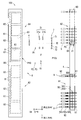
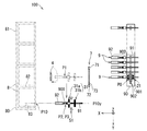
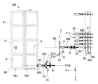
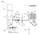
- the terminal insertion device 100 inserts the terminal 92 at the end of the terminal-attached electric wire 9 into the cavity 81 of the connector 8 and includes at least one electric wire with terminal 9 and at least one connector 8 (see FIG. 17).
- the terminal insertion device 100 in the present embodiment is a device that manufactures a wiring module 200 including a plurality of electric wires with terminals 9 and a plurality of connectors 8.
- the wiring module 200 alone is bundled in a form along a wiring path in a vehicle or the like, and is configured as a wire harness for electric wiring in the vehicle.
- the wiring module 200 is combined with at least one of other wiring modules and electric wires and bundled along a wiring path in a vehicle or the like, and configured as a wiring harness for electric wiring in the vehicle. .
- each component does not necessarily match the details of shape and size between FIGS. 1 and 2.
- the display of some mechanisms shown in FIG. 1 is omitted.
- the terminal insertion device 100 includes an electric wire arrangement member transfer mechanism 1, a first holding part related mechanism 2, a second holding part related mechanism 3, a third holding part 4, a fourth holding part related mechanism 5, a connector arrangement member transfer mechanism 6, An optical sensor 7 and a control unit 10 are provided.
- the first clamping unit-related mechanism 2, the second clamping unit-related mechanism 3, the third clamping unit 4, and the fourth clamping unit-related mechanism 5 are collectively referred to as a terminal insertion mechanism. It is not essential that the terminal insertion device 100 has all of these configurations.
- Each of the terminal-attached electric wires 9 includes an electric wire 91 and a terminal 92.
- the electric wire 91 is an insulated wire having a linear conductor and an insulating coating covering the periphery of the conductor.
- the terminal 92 is a conductive member such as metal. The terminal 92 is connected to the end of the electric wire 91.
- the terminal 92 in this embodiment is a crimp terminal, a conductor crimping portion 92a crimped to a conductor exposed at the end of the electric wire 91, a coated crimping portion 92b crimped to an insulating coating portion of the electric wire 91, and a counterpart It has the connection part 92c provided for a connection with a side terminal (refer FIG. 2).
- connection portion 92c has a cylindrical (for example, rectangular) male terminal shape, or a flat or pin-shaped male terminal shape.
- Each of the connectors 8 is a member in which a plurality of cavities 81 for accommodating the terminals 92 of each of the terminal-attached electric wires 9 are formed.
- the main body that forms the outer shape of the connector 8 is a non-conductive member, for example, a synthetic material such as polypropylene (PP), polyethylene (PE), polyvinyl chloride (PVC), polyethylene terephthalate (PET), or polyamide (PA). It is a resin member.
- the connector 8 may include a bus bar (not shown) in contact with the terminal 92 of the terminal-attached electric wire 9 inserted into the cavity 81 in the main body.
- the connector 8 is formed with a cavity 81 into which the terminals 92 can be inserted in a predetermined arrangement form.
- a lance or the like is provided in the cavity 81 as a locking structure capable of retaining and locking the terminal 92.
- the terminal 92 is inserted into the cavity 81, the lance or the like is retained and locked to the terminal 92. As a result, the terminal 92 is held in the cavity 81.
- the axial direction of the terminal 92 is inclined with respect to the axial direction of the cavity 81. For this reason, there exists a possibility that the terminal 92 may be caught in the cavity 81, and the insertion operation of the terminal 92 is not stable. For this reason, it is preferable to hold the connector 8 in a constant posture as much as possible.
- the electric wire arrangement member transfer mechanism 1 is a mechanism that moves the electric wire arrangement member 90 while detachably holding it.
- the electric wire arraying member 90 has a long base 901 and a plurality of electric wire fastening portions 902 formed upright from the base 901.
- Each of the wire fastening portions 902 includes a pair of members that sandwich and fasten a portion of the wire 91 of the terminal-attached wire 9 near the terminal 92 by elastic force.
- the plurality of wire fastening portions 902 are formed in a row at the base portion 901. Moreover, in the electric wire arrangement
- the arrangement direction of the wire fastening portions 902 is a direction orthogonal to the direction in which the tip of the terminal 92 of each of the terminal-attached electric wires 9 faces.
- the pair of members of the wire clamp portion 902 are members that can be elastically deformed, and clamp the electric wire 91 by elastic force generated by elastic deformation.
- the pair of members of the wire fastening portion 902 may be applied with an elastic force in a direction approaching each other by an elastic body such as a spring (not shown).
- each of the terminal-attached electric wires 9 fastened to the electric wire arraying member 90 has terminals 92 connected to both ends thereof.
- sequence member 90 is supporting the part of the electric wire 91 in each of the both ends of the some electric wire 9 with a terminal by the electric wire fastening part 902. Therefore, the electric wire arrangement
- sequence member 90 has pinched the electric wire 91 by the electric wire fastening part 902 in the location twice as many as the number of the electric wires 9 with a terminal.
- the electric wire array member transfer mechanism 1 includes a fixed seat 11 and a linear actuator 12.
- the fixed seat 11 is a part that detachably holds the electric wire arranging member 90.
- the fixed seat 11 is provided with an electric wire arrangement member locking mechanism 111 having a structure for holding the electric wire arrangement member 90 and releasing the holding.
- the electric wire arrangement member locking mechanism 111 for example, a known locking mechanism capable of holding the mating member by an engaging structure and releasing the holding can be adopted.
- the direction in which the tips of the terminals 92 of each of the terminal-attached electric wires 9 supported by the electric wire arranging member 90 in a state where the electric wire arranging member 90 is held by the fixed seat 11 is referred to as a first direction.
- the first direction is the horizontal direction.
- the one direction along the arrangement direction of the wire fastening portions 902 in the situation where the wire arrangement member 90 is held by the fixed seat 11 is referred to as a second direction.
- the second direction is orthogonal to the first direction.
- the second direction is also the horizontal direction.
- the X-axis positive direction is the first direction
- the Y-axis positive direction is the second direction.
- the fixed seat 11 has the terminal 92 of each of the terminal-attached electric wires 9 supported by the electric wire arraying member 90 facing the first direction, and the electric wire retaining portion 902 is arranged in the second direction orthogonal to the first direction. Hold along.
- the linear actuator 12 moves the fixed seat 11 along the second direction, that is, along the Y-axis direction.
- the linear actuator 12 moves the fixed seat 11 along the second direction, thereby moving the electric wire array member 90 fixed to the fixed seat 11 in a specified transfer direction (here, the second direction).
- the linear actuator 12 selectively positions each of the electric wire fastening portions 902 of the electric wire arrangement member 90 at a predetermined starting position P0.
- the linear actuator 12 is, for example, a known ball screw type electric actuator.
- the position of each of the wire fastening portions 902, that is, the position of each of the wires 91 fastened to the wire fastening portion 902 is known.
- the plurality of wire fastening portions 902 are arranged in a line at regular intervals from the reference position of the fixed seat 11. In this case, if a number indicating the number of the target wire retaining portion 902 from the end is designated, a linear for moving the target wire retaining portion 902 and the electric wire 91 secured thereto to the starting position P0.
- the operation amount of the actuator 12 (the transfer direction and transfer distance of the fixed seat 11) is determined.
- the electric wire arrangement member transfer mechanism 1 includes a first retracted position A1 where the entire electric wire arrangement member 90 deviates from the starting position P0 and a first operating position where a part of the electric wire arrangement member 90 is located at the starting position P0.
- the electric wire array member 90 can be moved along the first direction within a range extending to A2.
- the electric wire arrangement member 90 that supports the ends of the plurality of electric wires 9 with terminals, that is, the module of the electric wire arrangement member 90 is prepared for each wiring module 200, for example.
- an end region 900 a region extending from the terminal 92 in the terminal-attached electric wire 9 to a portion near the terminal 92 of the electric wire 91 is referred to as an end region 900.
- the connector arrangement member transfer mechanism 6 is a mechanism that moves the connector arrangement member 80 while detachably holding it.
- the connector arraying member 80 has a plurality of holders 82 corresponding to the plurality of connectors 8 to be held.
- the holder 82 is supported in a state of being aligned in a row.
- the holder 82 is a member formed of resin or the like, and is formed in a square tube shape having a bottom.
- the holder 82 is formed with a holding recess 83 that opens to one side of the holder 82.
- the holding recess 83 is formed in a shape corresponding to the outer shape of the connector 8.
- the connector 8 is housed and held in the holding recess 83 with the entrance of the cavity 81 facing the opening side of the holding recess 83. In this state, the connector 8 is held movably along the insertion direction of the terminal 92 with respect to the cavity 81 (also the extending direction of the cavity 81).
- the entire connector 8 may be accommodated in the holding recess 83, or the portion of the connector 8 on the inlet side of the cavity 81 may protrude outward from the opening of the holding recess 83.
- the connectors 8 are accommodated and held in the plurality of holders 82, respectively, so that the plurality of connectors are arranged in a line and the inlets of the cavities 81 are supported in the same direction. More specifically, the connector arraying member 80 is in a state in which the inlets of the cavities 81 of the plurality of connectors 8 face the same direction, and the arraying direction of the connectors 8 is orthogonal to the direction of the inlets of the cavities 81. The plurality of connectors 8 are supported.
- the holder 82 is not limited to the shape having the holding recess 83. Any configuration may be used as long as the connector 8 can be held in a fixed posture.
- the connector array member transfer mechanism 6 includes a fixed seat 61 and linear actuators 62 and 63.
- the fixed seat 61 is a portion that holds the connector arraying member 80 in a detachable manner.
- the fixed seat 61 is provided with a connector arrangement member locking mechanism 611 having a structure for holding the connector arrangement member 80 and releasing the holding.
- a lock mechanism similar to the wire array member lock mechanism 111 is employed as the connector array member lock mechanism 611.
- the fixed seat 61 detachably holds the connector arranging member 80 in a state in which the plurality of connectors 8 supported by the connector arranging member 80 are arranged in parallel to the arrangement direction of the wire fastening portions 902.
- the plurality of connectors 8 are arranged along the second direction, and the inlets of the cavities 81 of the plurality of connectors 8 are directed in the direction opposite to the first direction (X-axis negative direction).
- the connector arraying member 80 is held.
- the linear actuator 62 is, for example, a known ball screw type electric actuator or the like.
- the linear actuator 62 moves the fixed seat 61 along the second direction, that is, along the Y-axis direction.
- the linear actuator 62 selectively positions the cavities 81 of the connectors 8 supported by the connector arraying member 80 at predetermined terminal insertion positions P10 by moving the fixed seat 61 along the second direction.
- the terminal insertion position P10 is a position aligned with a third relay position P3 and an insertion completion position P4, which will be described later, in the second direction. That is, the coordinate P10y in the second direction representing the terminal insertion position P10 matches the coordinates in the second direction of the third relay position P3 and the insertion completion position P4.
- the linear actuator 62 When the linear actuator 62 positions each cavity 81, the linear actuator 62 is transported along the connector transport path along the second direction in a state where the plurality of holders 82 are arranged. That is, the fixed seat 61 and the linear actuator 62 of the connector arrangement member transfer mechanism 6 are an example of a holder transport mechanism that transports along the connector transport path in a state where a plurality of holders 82 are arranged.
- the linear actuator 63 is, for example, a known ball screw type electric actuator or the like.
- the linear actuator 63 moves the fixed seat 61 along the first direction by moving the linear actuator 62 along the first direction, that is, along the X-axis direction.
- the linear actuator 63 moves the tip of the terminal 92 of the terminal-attached electric wire 9 held by the second holding part 31 (first holding part) by moving the fixed seat 61 along the first direction.
- the linear actuator 63 is an example of a holder moving mechanism that allows the distal end portion of the terminal 92 of the terminal-attached electric wire 9 to enter the predetermined cavity 81 of the connector 8 held by the holder 82.
- the 3rd clamping part 4 is distribute
- each cavity 81 of each connector 8 is known.
- the positions of the cavities 81 on the connector arraying member 80 are determined by the positions at which the connectors 8 are held on the fixed seat 61 and the specifications of the shapes of the connectors 8.
- the identification code of each cavity 81 in each connector 8 and the position data on the fixed seat 61 corresponding to each identification code are set in advance.
- the position data in the second direction of the cavity 81 corresponding to the identification code is referred to move the target cavity 81 to the terminal insertion position P10.
- the operation amount of the linear actuator 62 (the transfer direction and transfer distance of the fixed seat 61) is determined.
- the target cavity 81 is an insertion destination of the terminal 92, and is sequentially selected from the plurality of cavities 81 of the plurality of connectors 8 supported by the connector arraying member 80.
- the target cavity 81 is one of the plurality of cavities 81 aligned along the third direction.
- the connector arraying member transfer mechanism 6 includes a second retracted position A3 in which the entire connector arraying member 80 is disengaged from the terminal insertion position P10 and a second part in which a part of the connector arraying member 80 is positioned at the terminal insertion position P10.
- the connector arraying member 80 can be moved along the first direction within a range extending to the operating position A4.
- the direction of the first retracted position A1 viewed from the first operating position A2 is the same as the direction of the second retracted position A3 viewed from the second operating position A4.
- the second retracted position A3 is located in the first direction (X-axis positive direction) when viewed from the first retracted position A1.
- a connector array member 80 that supports a plurality of connectors 8, that is, a module of the connector array member 80 is prepared for each set of wiring modules 200, for example.
- the plurality of connectors 8 are attached to a connector array member 80 prepared in advance according to the specifications of the shape of each connector 8. Then, the module of the connector arraying member 80 is transported from the place of other processes to the place of the terminal insertion device 100 and mounted on the connector arraying member transfer mechanism 6.
- the optical sensor 7 is a transmissive optical sensor and includes a light emitting unit 71 and a light receiving unit 72.
- the light emitting unit 71 outputs detection light 73 along a plane orthogonal to the straight path R0 passing through the starting position P0 when viewed from the third direction orthogonal to the first direction and the second direction.
- the detection light 73 is light that spreads in a sheet shape along a plane.
- the positive direction of the Z axis is the third direction.
- the third direction is a vertically upward direction.
- the light receiving unit 72 of the optical sensor 7 receives the detection light 73.
- the optical sensor 7 is a sensor that detects an object that blocks the detection light 73 by detecting whether or not the light receiving level of the light receiving unit 72 is lower than a preset level.
- the optical sensor 7 detects the tip portion of the terminal 92 of the terminal-attached electric wire 9 that blocks the detection light 73.
- the terminal insertion mechanism is a mechanism for inserting the terminal 92 of the electric wire 9 with terminal into the target cavity 81 located at the terminal insertion position P10.
- the terminal insertion mechanism removes the end region 900 of the terminal-attached electric wire 9 from the electric wire fastening portion 902 at the starting position P0 by holding and moving a part of the end region 900 of the electric wire 9 with the terminal.
- the terminal 92 in the end region 900 of the terminal-attached electric wire 9 is inserted into the target cavity 81 located at the terminal insertion position P10.
- This terminal insertion mechanism includes a first clamping portion 21 as a moving wire end holding portion to be described later, and a third direction transfer mechanism 22 as the wire end moving mechanism.
- the mechanism is used as a mechanism for moving through the first clamping portion 21 and inserting it into the cavity 81 of the connector 8.
- the first clamping unit-related mechanism 2 of the terminal insertion mechanism moves the end region 900 from the starting position P0 in advance by sandwiching and moving a part of the end region 900 of the terminal-attached electric wire 9. Move to position P1.
- the first clamping unit-related mechanism 2 includes a first clamping unit 21, a third direction transfer mechanism 22, and a first direction transfer mechanism 23.
- the first sandwiching portion 21 sandwiches a part of the end region 900 of the terminal-attached electric wire 9 with the tip of the terminal 92 facing the first direction from both sides along the second direction at the starting position P0.
- the first clamping unit 21 includes a pair of first opposing members 211 and a first separation / contact actuator 212 that brings the pair of first opposing members 211 close to and away from each other along the second direction (Y-axis direction). is doing.
- Each of the pair of first opposing members 211 has a bifurcated portion that is bifurcated from the root portion.
- the branch part of a pair of 1st opposing member 211 is two places of the both sides of the part which the electric wire fixing part 902 in the electric wire 91 of the electric wire 9 with a terminal pinches (namely, electric wire fixing part 902 among the edge parts of the electric wire 9 with a terminal). And support with the part (except the part held by) sandwiched.
- the 1st clamping part 21 can pinch and support the part between the part hold
- the one in the positive direction of the X-axis supports the portion in between.
- the first separation actuator 212 causes the pair of first opposing members 211 to approach or separate from each other along the second direction. As a result, the first separating / connecting actuator 212 switches the state of the pair of first opposing members 211 to either a state of holding the electric wire 91 or a state of releasing the holding of the electric wire 91.
- the first separating / connecting actuator 212 is, for example, a solenoid actuator or a ball screw type electric actuator.
- the 3rd direction transfer mechanism 22 of the 1st clamping part related mechanism 2 is a mechanism which moves the 1st clamping part 21 along a 3rd direction.
- the first direction transfer mechanism 23 of the first clamping unit-related mechanism 2 is a mechanism that moves the first clamping unit 21 along the first direction.
- the third direction transfer mechanism 22 and the first direction transfer mechanism 23 move the first clamping unit 21 along a plane (XZ plane) passing through the starting position P0 and along the first direction and the third direction. Accordingly, the first relay position P1 exists in a plane that passes through the starting position P0 and extends along the first direction and the third direction.
- the third direction transfer mechanism 22 moves along the third direction while directly supporting the first clamping unit 21, and the first direction transfer mechanism 23 supports the third direction transfer mechanism 22 while supporting the first direction 21. Move along one direction.
- the first direction transfer mechanism 23 includes a slide support 231 that supports the third direction transfer mechanism 22 so as to be movable along the first direction, and a linear that moves the third direction transfer mechanism 22 along the third direction. And an actuator 232.
- the third direction transfer mechanism 22 and the linear actuator 232 are, for example, a known ball screw type electric actuator or the like.
- the third direction transfer mechanism 22 and the first direction transfer mechanism 23 move the end region 900 of the terminal-attached electric wire 9 from the starting position P0 to the first relay position P1, the first direction transfer mechanism 23 is connected to the straight path R0.
- region 900 of the electric wire 9 with a terminal is moved along. More specific operations of the third direction transfer mechanism 22 and the first direction transfer mechanism 23 will be described later.
- the 3rd direction transfer mechanism 22 and the 1st direction transfer mechanism 23 of the 1st clamping part related mechanism 2 move the edge part 900 of the electric wire 9 with a terminal by moving the 1st clamping part 21, 1st relay position P1. It is an example of the 1st clamping part transfer mechanism made to move to.
- the third direction transfer mechanism 22 raises the first clamping part 21 from a position where the end of the terminal-attached electric wire 9 held by the electric wire holding part 902 can be held (lowered position) and another position (raised). It is used as an electric wire end moving mechanism that is moved between
- the third direction transfer mechanism 22 has the first clamping part 21 in the first direction (Z-axis direction), that is, the extending direction of the terminal-attached electric wire 9 held by the electric wire fastening part 902 (X-axis direction).
- the first clamping part 21 is moved forward and backward toward the electric wire fastening part 902 along the crossing direction (here, the Z-axis direction orthogonal to the X-axis direction).
- the wire end portion moving mechanism only needs to move the first clamping portion 21 in a direction crossing the X-axis direction, and the first clamping portion 21 is tilted with respect to the Z-axis direction. You may move forward and backward.
- the second clamping unit related mechanism 3 of the terminal insertion mechanism is a mechanism that inherits the support of the end region 900 of the terminal-attached electric wire 9 from the first clamping unit 21 at the first relay position P1. Furthermore, the second clamping unit-related mechanism 3 temporarily transfers the support of the terminal 92 of the terminal-attached electric wire 9 to and from the third clamping unit 4, and then the terminal-carrying electric wire to the fourth clamping unit-related mechanism 5. Deliver 9
- the second clamping unit related mechanism 3 includes a second clamping unit 31, a second direction transfer mechanism 33, and a third direction transfer mechanism 34.
- the second sandwiching portion 31 is configured so that a part of the terminal 92 and a portion of the wire 91 in the end region 900 of the terminal-attached electric wire 9 that the first sandwiching portion 21 sandwiches at the first relay position P1 in the second direction (Y (Axial direction) from both sides. And the 2nd clamping part 31 inherits the support of the edge part area
- the second clamping unit 31 includes a front second clamping unit 31a and a rear second clamping unit 31b. Each of the front 2nd clamping part 31a and the back 2nd clamping part 31b adjoins and separates a pair of 2nd opposing member 311 and a pair of 2nd opposing member 311 mutually along a 2nd direction (Y-axis direction). And a second separating / connecting actuator 312 to be operated.
- the pair of second opposing members 311 of the front second clamping portion 31a supports the terminal 92 in the end region 900 of the terminal-attached electric wire 9 with a part thereof being sandwiched therebetween.
- the pair of second opposing members 311 of the rear second clamping portion 31b supports a part of the electric wire 91 in the end region 900 of the terminal-attached electric wire 9 while sandwiching a part thereof.
- the operation of holding the nine electric wires 91 and the operation of releasing the holding can be performed individually.
- the second separating / connecting actuator 312 causes the pair of second opposing members 311 to approach or separate from each other along the second direction. As a result, the second separating / connecting actuator 312 changes the state of the pair of second opposing members 311 to either the state of holding the end region 900 of the terminal-attached electric wire 9 or the state of releasing the holding of the end region 900. Switch to.
- the second separation actuator 312 is, for example, a solenoid actuator or a ball screw type electric actuator.
- the 2nd direction transfer mechanism 33 of the 2nd clamping part related mechanism 3 is a mechanism which moves the 2nd clamping part 31 along a 2nd direction.
- the second direction transfer mechanism 33 moves the slide support portion 331 along the second direction, and the slide support portion 331 that supports the second holding portion 31 so as to be movable along the second direction. And a linear actuator 332 to be operated.
- the third direction transfer mechanism 34 supports the second direction transfer mechanism 33 so as to be movable in the third direction (Z-axis direction).
- the third direction transfer mechanism 34 is configured by, for example, a ball screw type electric actuator or the like.
- the third clamping part 4 of the terminal insertion mechanism holds a part of the terminal 92 in the end region 900 arranged at the predetermined first relay position P1 from both sides along the third direction.
- the third clamping unit 4 temporarily inherits the support of the terminal 92 of the terminal-attached electric wire 9 from the second clamping unit 31 and then delivers it to the second clamping unit 31 again.
- the third clamping unit 4 includes a pair of third opposing members 41, a third separating / contacting actuator 42 that causes the pair of third opposing members 41 to approach and separate from each other along the third direction (Z-axis direction), A first direction transfer mechanism 43 that moves the three opposing members 41 and the third separating / connecting actuator 42 along the first direction is provided.
- the pair of third opposing members 41 supports the terminal 92 in the end region 900 of the terminal-attached electric wire 9 with a part of the terminal 92 interposed therebetween.
- the third separation actuator 42 causes the pair of third opposing members 41 to approach or separate from each other along the third direction. Thereby, the 3rd separation / connection actuator 42 switches the state of a pair of 3rd opposing member 41 to either the state which clamps the terminal 92 of the electric wire 9 with a terminal, and the state which cancels
- the third separating / connecting actuator 42 is, for example, a solenoid actuator or a ball screw type electric actuator.
- the first direction transfer mechanism 43 moves the third opposing member 41 and the third separating / connecting actuator 42 along the first direction, so that the third direction transfer mechanism 43 moves the third counter member 41 and the third separation / contact actuator 42 in the first relay position P1.
- the opposing member 41 is relatively approached and separated.
- the first direction transfer mechanism 43 determines the positional relationship between the terminal 92 of the terminal-attached electric wire 9 held by the second clamping unit 31 and the third clamping unit 4 between the first positional relationship and the second positional relationship. Change.
- the first positional relationship is a positional relationship in which the third clamping unit 4 is separated from the terminal 92 in the first direction.
- the second positional relationship is a positional relationship in which the terminal 92 is positioned at the clamping position of the third clamping unit 4.
- the end region 900 of the terminal-attached electric wire 9 held by the second clamping unit 31 is moved closer to and away from the third opposing member 41. Also good.
- the 4th clamping part related mechanism 5 of a terminal insertion mechanism is a mechanism which inherits the support of the edge part area
- the fourth clamping unit-related mechanism 5 includes a fourth clamping unit 51, a third direction transfer mechanism 52, and a first direction transfer mechanism 53.
- the fourth holding part 51 holds each of a part of the terminal 92 and a part of the electric wire 91 in the end region 900 of the terminal-attached electric wire 9 held by the second holding part 31. And the 4th clamping part 51 inherits the support of the edge part area
- the fourth clamping unit 51 includes a pair of fourth opposing members 511 and a fourth separation / contact actuator 512 that causes the pair of fourth opposing members 511 to approach and separate from each other along the second direction (Y-axis direction). is doing.
- the pair of fourth opposing members 511 of the fourth sandwiching part 51 sandwich and support a part of the electric wire 91 in the end region 900 of the terminal-attached electric wire 9.
- the fourth separation actuator 512 causes the pair of fourth opposing members 511 to approach or separate from each other along the second direction.
- the fourth separation actuator 512 is configured to change the state of the pair of fourth opposing members 511 between a state in which the end region 900 of the terminal-attached electric wire 9 is sandwiched and a state in which the end region 900 is released. Switch to.
- the fourth separation / connection actuator 512 is, for example, a solenoid actuator or a ball screw type electric actuator.
- the fourth holding part 51 is a first holding part for insertion that can hold the end part of the terminal-attached electric wire 9 when the terminal 92 is inserted into the cavity 81 of the connector 8.
- the third direction transfer mechanism 52 of the fourth clamping unit related mechanism 5 is a mechanism for moving the fourth clamping unit 51 along the third direction.
- the third direction transfer mechanism 52 holds the electric wire 91 of the terminal-attached electric wire 9.
- the third direction transfer mechanism 52 is configured such that the distance difference in the third direction between the known third relay position P3 and the position of the target cavity 81 existing at the terminal insertion position P10, respectively.
- the fourth clamping unit 51 is moved in the third direction (Z-axis positive direction) by the amount.
- the third direction transfer mechanism 52 does not need to move the fourth clamping unit 51.
- the first direction transfer mechanism 53 moves the fourth clamping unit 51 in the first direction (X-axis positive direction) by a distance corresponding to the depth dimension of the target cavity 81.
- the first direction transfer mechanism 53 constitutes a relative movement mechanism that moves the fourth holding portion 51 that is the second holding portion for insertion in a direction in which the fourth holding portion 51 is relatively close to the holder 82 that holds the connector 8. .
- the terminal 92 of the terminal-attached electric wire 9 is inserted into the target cavity 81 existing at the terminal insertion position P10.
- the third direction transfer mechanism 52 moves along the third direction while directly supporting the fourth clamping unit 51, and the first direction transfer mechanism 53 supports the third direction transfer mechanism 52 while supporting the fourth direction 51. Move along one direction.
- the first direction transfer mechanism 53 includes a slide support portion 531 that supports the third direction transfer mechanism 52 movably along the first direction, and a linear that moves the third direction transfer mechanism 52 along the third direction. And an actuator 532.
- the third direction transfer mechanism 52 and the linear actuator 532 are, for example, a known ball screw type electric actuator or the like.
- the third direction transfer mechanism 52 and the first direction transfer mechanism 53 of the fourth holding part-related mechanism 5 move the fourth holding part 51 to move the terminal 92 of the terminal-attached electric wire 9 to the cavity 81 of each connector 8. It is an example of the 4th clamping part transfer mechanism to insert.
- the second direction transfer mechanism 33 of the second holding unit related mechanism 3 constitutes a second holding unit transfer mechanism that moves the second holding unit 31 along the second direction.
- the second direction transfer mechanism 33 moves the second clamping unit 31 to inherit the end region 900 of the terminal-attached electric wire 9 supported by the second clamping unit 31 from the third clamping unit 4. It moves between the first relay position P1 and the second relay position P2.
- the third direction transfer mechanism 34 of the second clamping unit related mechanism 3 constitutes a second clamping unit transfer mechanism that moves the second clamping unit 31 along the third direction.
- the third direction transfer mechanism 34 moves the second clamping unit 31 to move the end region 900 of the terminal-attached electric wire 9 supported by the second clamping unit 31 to the second relay position P2 and the fourth clamping unit 51.
- the terminal-attached electric wire 9 is moved to and from the third relay position P3.
- the terminal 92 is inserted into the cavity 81 of the connector 8 by the fourth clamping portion related mechanism 5 at the terminal insertion position P10.
- the control unit 10 is a device that controls each actuator in the wire arrangement member transfer mechanism 1, the terminal insertion mechanism, and the connector arrangement member transfer mechanism 6 while referring to the detection signal of the optical sensor 7. In FIG. 2, the display of the control unit 10 is omitted.
- the control unit 10 includes a calculation unit, a storage unit, and a signal interface.
- the arithmetic unit, the storage unit, and the signal interface are electrically connected.
- the calculation unit is an element or a circuit including a CPU (Central Processing Unit) that executes a process for deriving a control command for each actuator in accordance with a control program recorded in advance in the storage unit.
- a CPU Central Processing Unit
- the storage unit is a non-volatile memory that stores a control program and other data referred to by the arithmetic unit.
- the storage unit stores data such as predetermined path transfer data, terminal-cavity correspondence data, wire position data, and cavity position data.
- the predetermined path transfer data is data representing the operation procedure of the actuator of the first clamping section related mechanism 2 for moving the end region 900 of the terminal-attached electric wire 9 along the predetermined path from the starting position P0 to the linear path R0. Including. Further, the predetermined route transfer data includes the third relay position P3 through the first relay position P1 and the second relay position P2 from the position when the terminal 92 is detected by the optical sensor 7 in the end region 900, and the insertion completion. It also includes data representing the operating procedure of the actuator of the second clamping unit-related mechanism 3 for moving along the predetermined path to the position P4.
- the terminal-cavity correspondence data is data representing a correspondence relationship between each identification code of the wire retaining portion 902 sandwiching the electric wire 91 in the electric wire arraying member 90 and each identification code of the cavity 81 representing the insertion destination of the terminal 92. Further, the terminal-cavity correspondence data also represents the order of the wire fastening portions 902 that are to be positioned to the starting position P0.
- the electric wire position data includes data necessary for specifying the position of each of the electric wire fastening portions 902 in the electric wire arrangement member 90. That is, the electric wire position data includes data necessary for specifying the operation amount of the linear actuator 12 of the electric wire arrangement member transfer mechanism 1 when each of the electric wire holding portions 902 is moved to the starting position P0.
- the cavity position data specifies the position and depth dimension of each of the cavities 81 of each connector 8 supported by the connector arraying member 80 in the second direction (Y-axis direction) and the third direction (Z-axis direction). Including data necessary for.
- the positions of the inlets of the cavities 81 in the first direction (X-axis direction) are all the same known positions.
- the position data in the second direction of each of the cavities 81 in the cavity position data is obtained when the cavities 81 of each of the connectors 8 supported by the connector arraying member 80 are moved to the terminal insertion position P10.
- the third position and depth data of the cavity 81 in the cavity position data are obtained when the terminal 92 of the terminal-attached electric wire 9 is moved from the third relay position P3 into the target cavity 81.
- This is data for specifying the operation amounts of the third direction transfer mechanism 52 and the first direction transfer mechanism 53 of the related mechanism 5.
- the signal interface transmits the detection signal to the calculation unit. Further, when a control command for each actuator derived by the calculation unit is input, the signal interface converts the control command into a drive signal for each actuator and outputs the drive signal.
- the terminal insertion device 100 connects the terminals 92 of the electric wires with terminals 9 to the connectors 8. A terminal insertion step of inserting into each of the cavities 81 is executed.
- FIGS. 3 to 14 regarding the terminal insertion mechanism, only the portion sandwiching a part of the end region 900 of the terminal-attached electric wire 9 is schematically shown, and the display of other mechanisms is omitted. . Further, in FIG. 5 to FIG. 14, the display of the electric wire arrangement member transfer mechanism 1 and the connector arrangement member transfer mechanism 6 is omitted. Further, for convenience, with respect to the first clamping part 21, the second clamping part 31, the third clamping part 4 and the fourth clamping part 51, the state holding the end region 900 of the terminal-attached electric wire 9 is shown in black, The state where the end region 900 of the terminal-attached electric wire 9 is released is shown in white. FIG.
- FIG. 15 is a schematic perspective view of the terminal insertion device 100 that performs terminal insertion.
- the components of the terminal insertion device 100 mainly the second clamping unit 31, the third clamping unit 4, and the fourth clamping unit 51. Only the holder 82 and the terminal-attached electric wire 9 are schematically shown.
- the terminal insertion process includes a starting point / terminal insertion positioning process (FIG. 3), a clamping start process (FIG. 4), a first transfer primary process (FIG. 5), a first transfer secondary process (FIG. 6), a first delivery process ( 7), second transfer step (FIG. 8), second transfer step (FIG. 9), third transfer step (FIG. 10), holder moving step (FIG. 11), third transfer step (FIG. 12), fourth A transfer process (FIG. 13) and a return process (FIG. 14) are included.
- the mechanism that operates in each process operates in accordance with the control command of the arithmetic unit that executes the control program stored in the storage unit in the control unit 10.
- the calculation unit of the control unit 10 outputs a control signal to each mechanism through the signal interface while referring to various data stored in the storage unit and the detection result of the optical sensor 7, so The process is executed.
- the module of the electric wire arranging member 90 is fixed to the fixing seat 11 in a state where the electric wire arranging member transfer mechanism 1 places the fixing seat 11 at the first retracted position A1. . Further, the module of the connector array member 80 is fixed to the fixed seat 61 in a state where the connector array member transfer mechanism 6 places the fixed seat 61 at the second retracted position A3.
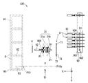
- FIG. 3 is a schematic plan view of the terminal insertion device 100 that performs the starting point / terminal insertion positioning step.
- the starting point / terminal insertion positioning step includes a starting point positioning step and a terminal insertion positioning step.
- the starting point positioning step is a step in which the electric wire arranging member transfer mechanism 1 selectively positions each of the electric wire fastening portions 902 of the electric wire arranging member 90 at the starting point position P0.
- the control unit 10 sequentially specifies the target wire fastening portion 902 to be moved to the starting position P0 based on the terminal-cavity correspondence data in the storage unit.
- sequence member transfer mechanism 1 moves the electric wire arrangement
- the connector arraying member transfer mechanism 6 moves the connector arraying member 80 along the second direction, so that each cavity 81 of each connector 8 is selectively inserted in the terminal insertion position in the second direction.
- the control unit 10 sequentially specifies the target cavity 81 to be moved to the terminal insertion position P10 based on the terminal-cavity correspondence data in the storage unit.
- the connector arraying member transfer mechanism 6 moves the connector arraying member 80 along the second direction, thereby positioning the target cavity 81 specified by the control unit 10 at the terminal insertion position P10.
- the connector array member transfer mechanism 6 does not move the connector array member 80 in this step.
- the starting point positioning step and the terminal insertion positioning step may be performed in parallel, or may be performed in an appropriate order.
- the starting point / terminal insertion positioning step is executed. And every time the starting point / terminal insertion positioning process is executed, the clamping start process, the first transfer primary process, the first transfer secondary process, the first transfer process, the second transfer process, the second transfer process, which will be described later, A three-transfer process, a holder moving process, a third delivery process, and a fourth transfer process are performed.
- step 3 is a first starting point / terminal insertion positioning step, and this step is also an operation position transition step.
- the operation position transition process includes a first operation position transition process.
- the electric wire arrangement member transfer mechanism 1 moves the electric wire arrangement member 90 that supports the end regions 900 of the plurality of terminal-attached electric wires 9 from the first retracted position A1 to the first operation position A2. .
- the operating position transition process includes a second operating position transition process.
- the connector array member transfer mechanism 6 moves the connector array member 80 that supports the plurality of connectors 8 from the second retracted position A3 to the second operation position A4.
- first operation position transition process and the second operation position transition process may be performed in parallel, or may be performed in an appropriate order.
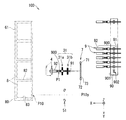
- FIG. 4 is a schematic plan view of the terminal insertion device 100 that performs the clamping start process.
- the first clamping unit 21 is configured to detect the end region 900 in the terminal-attached electric wire 9 in a state where the tip of the terminal 92 faces the first direction at a predetermined starting position P0. It is a process with a part in between.
- the 1st clamping part 21 has 2 places of the electric wire 91 in the edge part area
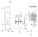
- FIG. 5 is a schematic plan view of the terminal insertion device 100 that performs the first transfer primary process. As shown in FIG. 5, the first transfer primary process is performed after the third direction transfer mechanism 22 of the first holding unit related mechanism 2 moves the first holding unit 21 in the third direction by a predetermined distance. The first direction transfer mechanism 23 of the first clamping unit-related mechanism 2 moves in the first direction along the straight path R0.
- the first direction transfer mechanism 23 of the first clamping unit-related mechanism 2 moves the first clamping unit 21 at a first speed by a predetermined first distance along a predetermined linear path R0.
- the first distance is set in a range in which the terminal 92 does not reach the detection light 73 regardless of variations in the initial position of the electric wire 9 with terminal.
- the first direction transfer mechanism 23 moves the first clamping unit 21 at a second speed slower than the first speed along the predetermined linear path R0 until the optical sensor 7 detects the tip of the terminal 92. .
- the above operation prevents the positioning error of the terminal 92 from becoming so large that it cannot be ignored due to a delay in the feedback control for controlling the first direction transfer mechanism 23 according to the detection result of the optical sensor 7. Further, the above operation increases the transfer speed of the terminal-attached electric wire 9 while reducing the positioning error of the terminal 92 and shortens the execution time of the process.
- FIG. 6 is a schematic plan view of the terminal insertion device 100 that performs the first transfer secondary process.
- the first direction transfer mechanism 23 of the first holding unit related mechanism 2 moves the first holding unit 21 through the straight path from the time when the optical sensor 7 detects the terminal 92.
- the third direction transfer mechanism 22 of the first clamping unit-related mechanism 2 is opposite to the third direction (Z-axis) by a predetermined distance. This is a step of moving in the negative direction. By this step, the end region 900 of the terminal-attached electric wire 9 moves to the first relay position P1.
- FIG. 7 is a schematic plan view of the terminal insertion device 100 that performs the first delivery step.
- the second holding portion 31 is a part of the terminal 92 in the end region 900 of the terminal-attached electric wire 9 held by the first holding portion 21 at the first relay position P1.
- part of the electric wire 91 is sandwiched from both sides along the second direction.
- the first clamping unit 21 releases the clamping of the electric wire 91.
- the second clamping unit 31 inherits the support of the terminal-attached electric wire 9 from the first clamping unit 21.
- the step in which the second clamping unit 31 holds the terminal-attached electric wire 9 corresponds to the first holding step.
- FIG. 8 is a schematic plan view of the terminal insertion device 100 that performs the second transfer step.
- the first direction transfer mechanism 43 of the third clamping unit 4 moves the third opposing member 41 in the reverse direction of the first direction (X-axis negative direction) by a predetermined distance. It is the process of moving to.
- the first direction transfer mechanism 43 moves the third facing member 41 away from the end region 900 of the terminal-attached electric wire 9 at the first relay position P1 to the position where the third facing member 41 is sandwiched. Move.
- FIG. 9 is a schematic plan view of the terminal insertion device 100 that performs the second delivery step.
- the third clamping unit 4 is a part of the terminal 92 in the end region 900 of the terminal-attached electric wire 9 that is held by the second clamping unit 31. Is temporarily sandwiched from both sides along the third direction.
- the front second clamping part 31a temporarily releases the terminal 92 when the third clamping part 4 holds the terminal 92, and holds the terminal 92 again. That is, the third clamping unit 4 temporarily transfers the support of the terminal 92 of the terminal-attached electric wire 9 from the second clamping unit 31 and then delivers it to the second clamping unit 31.
- the rear second clamping portion 31b like the front second clamping portion 31a, temporarily releases the electric wire 91 when the third clamping portion 4 holds the terminal 92, and again It is also conceivable to hold the electric wire 91 therebetween.
- the second transfer step instead of bringing the third holding portion 4 closer to the terminal-attached electric wire 9, the second holding portion 31 moves the terminal-attached electric wire 9, and the second delivery step is performed. Also good. In this case, since the movement of the third clamping unit 4 along the first direction becomes unnecessary, the first direction transfer mechanism 43 is omitted, and a moving mechanism that moves the second clamping unit 31 along the first direction is provided. What is necessary is just to provide.
- FIG. 10 is a schematic plan view of the terminal insertion device 100 that performs the third transfer step.
- the third transfer step is a step in which the second direction transfer mechanism 33 of the second holding unit related mechanism 3 moves the second holding unit 31 in the second direction by a predetermined distance.
- the second direction transfer mechanism 33 moves the end region 900 from the predetermined first relay position P1 to the predetermined second relay position P2.
- the third direction transfer mechanism 34 moves the end region 900 from the second relay position P2 to the third relay position P3.
- the first relay position P ⁇ b> 1 is a position where the second clamping unit 31 inherits the support of the terminal 92 from the third clamping unit 4. Further, as shown in FIG.
- the second relay position P2 is a position where the second clamping unit 31 changes the direction of movement from the second direction to the third direction.
- the third relay position P3 is a position where the distal end portion of the terminal-attached electric wire 9 (the distal end portion of the terminal 92) is inserted into the target cavity 81, and the second sandwiching portion 31 is connected to the fourth sandwiching portion 51. This is the position where the support of the attached wire 9 is handed over.
- FIG. 11 is a schematic plan view of the terminal insertion device 100 that performs the holder moving step.
- the linear actuator 63 moves the holder 82 from the first holder position P81 to the second holder position P82 along the first direction, and the second clamping unit 31 (first In this step, only the distal end portion of the terminal-attached electric wire 9 held by one holding portion enters the target cavity 81.
- the linear actuator 63 is an example of a holder moving mechanism that moves the holder 82 toward the distal end portion of the terminal 92 of the terminal-attached electric wire 9 held by the second clamping unit 31.
- the distal end of the terminal-attached electric wire 9 enters the cavity 81 while being arranged at the third relay position P3. That is, the third relay position P3 is the position of the terminal 92 of the terminal-attached electric wire 9 in a state where only the tip of the terminal-attached electric wire 9 enters the cavity 81 of the connector 8 held by the holder 82 at the second holder position P82. (First terminal position).
- the first holder position P81 is a position of the holder 82 that holds the connector 8 in which the target cavity 81 is arranged at the terminal insertion position P10. For this reason, the first holder position P81 is the position of the holder 82 when the tip of the terminal-attached electric wire 9 held by the second holding part 31 (first holding part) faces the target cavity 81. .
- the second holder position P82 is the position of the holder 82 moved from the first holder position P81 along the first direction (specifically, in the negative direction of the X axis).
- the distance from the first holder position P81 to the second holder position P82 is from the tip position of the terminal-attached electric wire 9 in the state where the end region 900 is at the third relay position P3 to the entrance of the cavity 81 at the terminal insertion position P10. It corresponds to the distance to the position.
- the holder moving process corresponds to a first insertion process in which the tip of the terminal-attached electric wire 9 enters the cavity 81. After the holder moving process is executed, a third delivery process described below is executed.
- FIG. 12 is a schematic plan view of the terminal insertion device 100 that performs the third delivery step.
- the end portion 900 of the terminal-attached electric wire 9 supported by the second holding portion 31 is supported by the fourth holding portion 51 in a state where the end region 900 is at the third relay position P3. This is a step of sandwiching a part of the electric wire 91 in the region 900.
- the second clamping unit 31 releases the clamping of the end region 900 while the fourth clamping unit 51 holds the electric wire 91 therebetween.
- the 4th clamping part 51 inherits the support of the electric wire 9 with a terminal from the 2nd clamping part 31 by performing a 3rd delivery process.
- a part of the terminal-attached electric wire 9 (here, the electric wire 91) held by the second holding unit 31 that is the first holding unit is held in the fourth holding unit that is the second holding unit.
- the release of the support of the terminal-attached electric wire 9 by the second clamping unit 31 is performed by the second separating / connecting actuator 312 in each of the pair of second opposing members 311 of the front second clamping unit 31a and the rear second clamping unit 31b. It is performed by moving in a direction (a direction along the second direction) that is isolated from the terminal-attached electric wire 9.
- a 3rd delivery process includes the isolation process which moves the 2nd clamping part 31 in the direction isolated from the electric wire 9 with a terminal.
- the second separating / connecting actuator 312 is a configuration example of the first holding unit moving mechanism.
- the end region 900 held by the second holding unit 31 may be held, and the fourth holding unit 51 may also hold the end region 900.
- the delivery to the fourth clamping unit 51 can be quickly performed by performing the isolation process immediately after the holder transfer process is completed.
- FIG. 13 is a schematic plan view of the terminal insertion device 100 that performs the fourth transfer process.
- the first direction transfer mechanism 53 of the fourth holding unit-related mechanism 5 moves the fourth holding unit 51 to insert the distal end portion of the terminal-attached electric wire 9 into the terminal.
- This is a step of moving to the back of the cavity 81 at the position P10.
- the fourth transfer process corresponds to a second insertion process in which the terminal 92 is inserted into the cavity 81.
- the first direction transfer mechanism 53 moves the fourth clamping portion 51 to the depth of the target cavity 81.
- the end region 900 of the terminal-attached electric wire 9 moves from the third relay position P3 to the insertion completion position P4 on the back side of the target cavity 81.
- This insertion completion position P4 corresponds to the position of the terminal 92 (second terminal position) in which the distal end portion of the terminal-attached electric wire 9 is inserted into the back of the cavity 81.
- the linear actuator 63 moves the holder 82 along the first direction in the state where the fourth clamping unit 51 fixes the terminal-attached electric wire 9 to the third relay position P3, and the cavity 81 is moved to the cavity 81.
- tip part of the electric wire 9 with a terminal may be sufficient. That is, the fourth transfer process may be a process of moving the end region 900 of the terminal-attached electric wire 9 relative to the connector 8.
- FIG. 14 is a schematic plan view of the terminal insertion device 100 that performs the returning step.
- the returning step is a step in which the linear actuator 63 moves the holder 82 at the second holder position P82 to the first holder position P81 (see FIG. 11).
- the terminal-attached electric wire 9 that has been inserted in the previous fourth transfer step also moves together.
- the linear actuator 62 moves the holder 82 along the second direction so that the target cavity 81 is moved. The terminal is moved to the terminal insertion position P10.
- the terminal insertion device 100 executes the steps shown above, one terminal 92 of the terminal-attached electric wire 9 is inserted into the cavity 81 of the connector 8. Then, the terminal insertion device 100 repeats the execution of each process described above until the insertion of the terminal 92 into the cavity 81 of each of the plurality of connectors 8 supported by the connector arraying member 80 is completed.
- the connector arraying member transfer mechanism 6 moves the connector arraying member 80 from the second operating position A4 to the second retracted position A3. Move. Further, the electric wire arranging member transfer mechanism 1 moves the electric wire arranging member 90 from the first operating position A2 to the first retracted position A1.
- the electric wire array member 90 and the connector array member 80 are replaced at the first retracted position A1 and the second retracted position A3.
- the connector arraying member 80 removed from the connector arraying member transfer mechanism 6 at the second retracted position A3 connects the plurality of connectors 8 constituting one set of wire harnesses or one set of subwire harnesses to the terminals 92 of the terminal-attached electric wires 9. Is supported in a lump with the inserted.
- the connector arrangement member 80 removed at the second retracted position A3 is transported to the next process place while supporting the plurality of connectors 8 into which the terminals 92 of the terminal-attached electric wires 9 are inserted.
- a plurality of terminal-attached electric wires 9 and a plurality of connectors 8 are provided, and the terminals 92 of the plurality of terminal-attached electric wires 9 are integrally inserted in the cavity 81 of the connector 8.
- An integrated wiring module 200 is manufactured.
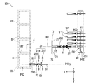
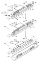
- FIG. 16 is a schematic perspective view for explaining the operation of the discharge mechanism. As shown in FIG. 16, a discharge mechanism 13 and a tray part 14 are provided in the vicinity of the first retracted position A ⁇ b> 1 of the wire arrangement member transfer mechanism 1.
- the discharge mechanism 13 includes a pressing member 131, a linear actuator 132, and a long plate portion 133. Each of these components of the discharge mechanism 13 is provided on the first direction side (X-axis positive direction side) of the electric wire arrangement member transfer mechanism 1.
- the pressing member 131 is a member having a predetermined rigidity formed in a plate shape.
- the linear actuator 132 is configured by a known ball screw type electric actuator or the like.
- the pressing member 131 moves forward and backward along the first direction by the linear actuator 132.
- the forward / backward movement direction (first direction) of the pressing member 131 is a direction (here, a direction orthogonal) intersecting the transfer direction (second direction) of the wire array member 90 by the linear actuator 12.
- the pressing member 131 moves in the direction opposite to the first direction, thereby pressing the wire arranging member 90 released from the lock holding by the electric wire arranging member locking mechanism 111 in the direction opposite to the first direction.
- the electric wire arrangement member 90 transferred to the first retracted position A1 is discharged from the electric wire arrangement member transfer mechanism 1.
- discharge the electric wire arrangement member 90 from the electric wire arrangement member transfer mechanism 1 means that the used electric wire arrangement member 90 is removed from the electric wire arrangement member transfer mechanism 1.
- the “removed state” means a state where at least a new wire arrangement member 90 holding the electric wire 9 with a terminal in each of the electric wire fastening portions 902 can be installed at the first retracted position A1 of the electric wire arrangement member transfer mechanism 1. More preferably, it means a state in which the new electric wire arrangement member 90 can be held by the electric wire arrangement member locking mechanism 111.
- the long plate portion 133 is a plate-like member that extends along the linear actuator 12.
- the long plate portion 133 is fixed to the linear actuator 12 or the like.
- the long plate portion 133 prevents the electric wire arrangement member 90 from falling to the first direction side (X-axis positive direction side) when the lock holding of the electric wire arrangement member 90 by the electric wire arrangement member locking mechanism 111 is released.
- the position of the upper end (end portion on the third direction side) of the long plate portion 133 is the lower end (end portion on the opposite side to the third direction) of the terminal 92 of the terminal-attached electric wire 9 set in the wire fastening portion 902. It is arranged on the lower side.
- An elongated through hole 134 extending in the second direction is formed at the center of the long plate portion 133 so that the pressing member 131 can penetrate along the first direction.
- the pressing member 131 is held by the linear actuator 132 in a state of being inserted through the through hole 134.
- the pressing member 131 moves through the through hole 134 in a direction approaching or separating from the electric wire arraying member 90.
- a concave notch that allows the pressing member 131 to move can be formed in the central upper end portion or the central lower end portion of the long plate portion 133.
- the long plate portion 133 may be composed of a plurality of plate-like members respectively provided on both sides of the pressing member 131 in the second direction.
- the tray portion 14 is located on the opposite side (X-axis negative direction side) from the first direction of the electric wire arrangement member transfer mechanism 1 and in the direction opposite to the third direction from the electric wire arrangement member transfer mechanism 1 (Z It is arranged at a position separated by a predetermined distance in the negative axis direction).
- the tray part 14 is a member formed in a bowl shape opened to the third direction side.
- the tray unit 14 receives the electric wire arrangement member 90 discharged from the electric wire arrangement member transfer mechanism 1 by being pressed by the pressing member 131 of the discharge mechanism 13.
- the electric wire arrangement member 90 holding the electric wires 9 with terminals in the electric wire fastening portions 902 is installed at the first retracted position A1 of the electric wire arrangement member transfer mechanism 1, the electric wire arrangement member transfer mechanism 1 performs the first operation. It is transferred to position A2 (supply position) (supply position moving step, see FIG. 3). And the some electric wire 9 with a terminal hold
- each of the terminal-attached electric wires 9 sequentially removed is transferred by the terminal insertion mechanism, and the terminal 92 at the tip thereof is inserted into the target cavity 81 of the connector 8 held by the holder 82 (terminal insertion step, (See FIGS. 4 to 15).
- the wire arraying member 90 that has completed the supply of the terminal-attached wire 9 to the terminal insertion mechanism by removing all the terminal-attached wires 9 is moved from the first operating position A2 by the wire arraying member transfer mechanism 1. It is transferred to the one save position A1 (the save position) (FIG. 16: save position moving step S11).
- the lock holding of the wire arranging member 90 by the wire arranging member locking mechanism 111 is released (FIG. 16: holding releasing step S12).
- sequence member locking mechanism 111 is comprised by the U-shaped lock member which pinches
- the electric wire arrangement member 90 is discharged from the electric wire arrangement member transfer mechanism 1 (FIG. 16: discharge step S13). Specifically, the linear actuator 132 moves the pressing member 131 in the direction opposite to the first direction. Specifically, the linear actuator 132 presses until the end of the pressing member 131 that contacts the electric wire arraying member 90 (the end opposite to the end in the first direction) exceeds the center in the first direction of the fixed seat 11. The member 131 is moved.
- the movement range of the pressing member 131 is not particularly limited as long as the electric wire arrangement member 90 can be discharged from the electric wire arrangement member transfer mechanism 1.
- the electric wire arrangement member 90 released from the holding of the electric wire arrangement member locking mechanism 111 is pressed in the direction opposite to the first direction and discharged from the electric wire arrangement member transfer mechanism 1. Then, the discharged electric wire arraying member 90 falls downward and is received in the tray portion 14.
- illustration is abbreviate
- the electric wire arranging member 90 can be easily discharged with a simple configuration.
- the linear actuator 63 moves the holder 82 to the second holder position P82 so that the tip of the terminal-attached electric wire 9 held by the second clamping unit 31 is brought into the holder 82. It is possible to enter the cavity 81 of the held connector 8. In this manner, by not changing the end region 900 in the terminal 92 until the terminal 92 of the terminal 92 enters the cavity 81 after the second holding portion 31 holds the terminal 92 of the electric wire 9 with terminal. It is possible to suppress the posture of the terminal 92 from changing. Therefore, the tip end of the terminal 92 can be satisfactorily inserted into the back side of the cavity 81.
- the second clamping unit 31 includes the front second clamping unit 31a and the rear second clamping unit 31b provided integrally with the slide support unit 331.
- the front second clamping part 31a and the rear second clamping part 31b inherit the holding of the terminal-attached electric wire 9 from the third clamping part 4, and then, by the second direction transfer mechanism 33 and the third direction transfer mechanism 34, It moves integrally in the second direction and the third direction.
- the relative positional relationship of the front 2nd clamping part 31a and the back 2nd clamping part 31b does not change. Therefore, it is possible to prevent the terminal 92 from changing the posture while reliably supporting the terminal-attached electric wire 9. Thereby, the terminal 92 can be inserted satisfactorily.
- the second holding part 31 (the front second holding part 31a and the rear second holding part 31b) corresponding to the first holding part holds the electric wire 91 and the terminal 92 of the terminal-attached electric wire 9. It is configured. However, it is not essential for the first holding unit to hold both the electric wire 91 and the terminal 92, and it is sufficient that the first holding unit is configured to hold at least the terminal 92.
- the 4th clamping part 51 corresponded to a 2nd holding part is comprised so that the electric wire 91 may be contacted and this may be hold
- the second holding portion it is not essential for the second holding portion to hold the electric wire 91.
- the second holding portion may be configured to contact and hold the terminal 92.
Landscapes
- Engineering & Computer Science (AREA)
- Manufacturing & Machinery (AREA)
- Manufacturing Of Electrical Connectors (AREA)
Abstract
Provided is a technique for inserting terminals into a connector adequately. The terminal inserting device (100) is a device whereby a terminal (92) at a forward extremity of a terminal-equipped wire (9) is inserted into a cavity (81) formed in a connector (8). The terminal inserting device (100) comprises: a holder (82) holding the connector (8); a wire alignment member (90) whereby the plurality of terminal-equipped wires (9) are held aligned in one direction; a wire alignment member transport mechanism (1) holding the wire alignment member (90) while transporting the wire alignment member (90) between a first retreat position (A1) and a first operating position (A2) along a second direction; a terminal inserting mechanism (2, 3, 5) whereby the terminal-equipped wire (9) is received from the terminal-equipped wire (9) disposed at the first retreat position (A1), and inserted into the cavity (81) of the connector (8); and a removal mechanism (13) whereby the wire alignment member (90) moved from the first operating position (A2) to the first retreat position (A1) is removed from the wire alignment member transport mechanism (1).
Description
この発明は、電線端部の端子をコネクタに挿入するための技術に関する。
This invention relates to a technique for inserting a terminal at an end of an electric wire into a connector.
特許文献1は、固定具によって保持されたコネクタハウジングに、端子を挿入する装置を開示している。
Patent Document 1 discloses a device for inserting a terminal into a connector housing held by a fixture.
特許文献1に記載の挿入装置では、端子付電線の端子の先端部が一対の案内爪及び端子押さえの間で把持され、端子の中間部が一対の端子把持爪で把持され、さらに、端子付電線の電線が一対の電線挟持爪で挟持される。そして、コネクタハウジングの端子収容室に対して、端子付電線を位置決めされた後、一対の案内爪及び端子押さえの把持力が緩和された状態で、端子爪と電線挟持爪がコネクタハウジングに向けて移動させ、端子の先端部が端子収容室に挿入される。次いで、端子保持爪を端子収容室から隔離し、さらに電線挟持爪を移動させることによって、端子が端子収容室内に完全に挿入される。
In the insertion device described in Patent Document 1, the tip of the terminal of the electric wire with terminal is gripped between the pair of guide claws and the terminal presser, the middle part of the terminal is gripped with the pair of terminal gripping claws, and The electric wire of an electric wire is clamped with a pair of electric wire clamping claws. Then, after the terminal-equipped electric wire is positioned with respect to the terminal housing chamber of the connector housing, the terminal claws and the electric wire clamping claws are directed toward the connector housing in a state where the gripping force of the pair of guide claws and the terminal retainer is relaxed. The tip of the terminal is inserted into the terminal accommodating chamber. Next, the terminal is completely inserted into the terminal accommodating chamber by isolating the terminal holding claw from the terminal accommodating chamber and further moving the electric wire clamping claw.
しかしながら、上記従来技術の場合、端子保持爪及び電線挟持爪を個別に移動させるため、これらの駆動部を同期させて動作させる必要があった。このため、同期が適切に行われなかった場合、端子収容室内に端子付電線の先端部が進入するまでに、端子の姿勢が変化することによって、端子をコネクタに挿入することが困難となるおそれがあった。
However, in the case of the above prior art, since the terminal holding claws and the electric wire clamping claws are individually moved, it is necessary to operate these drive units in synchronization. For this reason, when synchronization is not properly performed, it is difficult to insert the terminal into the connector due to a change in the attitude of the terminal before the tip of the electric wire with terminal enters the terminal accommodating chamber. was there.
そこで、本発明は、コネクタに対する端子挿入を良好に行う技術を提供することを目的とする。
Therefore, an object of the present invention is to provide a technique for favorably inserting a terminal into a connector.
上記の課題を解決するため、第1の態様は、コネクタに形成されたキャビティに、端子付電線における先端の端子を挿入する端子挿入装置であって、コネクタを保持するホルダと、複数の端子付電線を一方向に並べて保持する電線配列部材と、前記電線配列部材を保持しつつ、前記電線配列部材を規定の移送方向に沿って供給位置と待避位置との間で移送する移送機構と、前記供給位置に配された前記電線配列部材から、前記端子付電線を受け取り、前記コネクタのキャビティに挿入する端子挿入機構と、前記供給位置から前記待避位置に移動した前記電線配列部材を前記移送機構から排出する排出機構とを備える。
In order to solve the above problems, a first aspect is a terminal insertion device for inserting a terminal at a tip of a terminal-attached electric wire into a cavity formed in a connector, the holder holding the connector, and a plurality of terminals A wire arrangement member that holds and arranges the electric wires in one direction; a transfer mechanism that transfers the wire arrangement member between a supply position and a retracted position along a specified transfer direction while holding the wire arrangement member; The terminal insertion mechanism that receives the terminal-attached electric wire from the electric wire arrangement member arranged at the supply position and inserts it into the cavity of the connector, and the electric wire arrangement member that has moved from the supply position to the retracted position from the transfer mechanism. A discharge mechanism for discharging.
また、第2の態様は、第1の態様に係る端子挿入装置であって、前記移送機構は、前記電線配列部材の両端部を挟んで前記電線配列部材を保持する電線配列保持部を含み、前記排出機構は、前記電線配列部材を前記移送方向に交差する方向に押圧する押圧部材を含み、前記押圧部材は、前記電線配列保持部による保持が解除された状態の前記電線配列部材を押圧することによって、前記電線配列部材を前記移送機構から排出する。
Further, the second aspect is the terminal insertion device according to the first aspect, wherein the transfer mechanism includes an electric wire arrangement holding part that holds the electric wire arrangement member across both ends of the electric wire arrangement member, The discharge mechanism includes a pressing member that presses the electric wire arrangement member in a direction intersecting the transfer direction, and the pressing member presses the electric wire arrangement member in a state where the holding by the electric wire arrangement holding portion is released. As a result, the wire arrangement member is discharged from the transfer mechanism.
また、第3の態様は、第1または第2の態様に係る端子挿入装置であって、前記排出機構によって前記電線配列移送機構から排出された前記電線配列部材を受け取るトレイ部、をさらに備える。
The third aspect is a terminal insertion device according to the first or second aspect, further comprising a tray portion that receives the wire arrangement member discharged from the electric wire arrangement transfer mechanism by the discharge mechanism.
また、第4の態様は、コネクタに形成されたキャビティに、端子付電線における先端の端子を挿入する端子挿入方法であって、(A)電線配列部材移動機構が、複数の端子付電線を一列に並べて保持した電線配列部材を、規定の移送方向に沿って供給位置に移動させる供給位置移動工程と、(B)端子挿入機構が、供給位置にある前記電線配列部材から端子付電線を受け取って、ホルダに保持されたコネクタのキャビティに前記端子付電線の先端の端子を挿入する端子挿入工程と、(C)前記端子挿入工程の後、前記電線配列部材を、前記電線配列部材移動機構が前記移送方向に沿って前記供給位置から待避位置に移動させる待避位置移動工程と、(D)前記待避位置移動工程にて前記待避位置に移動した前記電線配列部材を、前記電線配列機構から排出する排出工程とを含む。
Moreover, a 4th aspect is a terminal insertion method which inserts the terminal of the front-end | tip in an electric wire with a terminal in the cavity formed in the connector, Comprising: (A) Electric wire arrangement member moving mechanism puts several electric wires with a terminal in a row. A supply position moving step of moving the wire arrangement member held side by side to a supply position along a specified transfer direction, and (B) the terminal insertion mechanism receives the electric wire with terminal from the electric wire arrangement member at the supply position. A terminal insertion step of inserting a terminal at the tip of the terminal-attached electric wire into the cavity of the connector held by the holder, and (C) after the terminal insertion step, the wire arrangement member is moved by the wire arrangement member moving mechanism. A retracted position moving step of moving from the supply position to the retracted position along the transfer direction, and (D) the wire arrangement member moved to the retracted position in the retracted position moving step And a discharge step of discharging the mechanism.
また、第5の態様は、コネクタのキャビティに、端子付電線の先端の端子が挿入された配線モジュールを製造する配線モジュール製造方法であって、(A)電線配列部材移動機構が、複数の端子付電線を一列に並べて保持した電線配列部材を、規定の移送方向に沿って供給位置に移動させる供給位置移動工程と、(B)端子挿入機構が、供給位置にある前記電線配列部材から端子付電線を受け取って、ホルダに保持されたコネクタのキャビティに前記端子付電線の先端の端子を挿入する端子挿入工程と、(C)前記端子挿入工程の後、前記電線配列部材を、前記電線配列部材移動機構が前記移送方向に沿って前記供給位置から待避位置に移動させる待避位置移動工程と、(D)前記待避位置移動工程にて前記待避位置に移動した前記電線配列部材を、前記電線配列機構から排出する排出工程とを含む。
Further, the fifth aspect is a wiring module manufacturing method for manufacturing a wiring module in which a terminal at a tip of a terminal-attached electric wire is inserted into a cavity of a connector, wherein (A) the electric wire arranging member moving mechanism includes a plurality of terminals. A supply position moving step of moving the electric wire arrangement member holding the attached electric wires in a line to the supply position along a prescribed transfer direction; and (B) the terminal insertion mechanism is attached with a terminal from the electric wire arrangement member at the supply position. A terminal insertion step of receiving an electric wire and inserting a terminal at a tip of the terminal-attached electric wire into a cavity of a connector held by a holder; and (C) after the terminal insertion step, the electric wire arrangement member is replaced with the electric wire arrangement member. A retracting position moving step in which the moving mechanism moves from the supply position to the retracted position along the transfer direction; and (D) the wire distribution moved to the retracted position in the retracted position moving step. The member includes a discharge step of discharging from the wire array mechanism.
第1から第3の態様に係る端子挿入装置によると、使用済の電線配列部材を取り出す作業をすることなく、新たな電線配列部材を迅速に設置できる。このため、端子挿入装置の稼動効率を向上できるため、端子挿入を効率的に行うことができる。
According to the terminal insertion device according to the first to third aspects, it is possible to quickly install a new electric wire arrangement member without taking out the used electric wire arrangement member. For this reason, since the operating efficiency of a terminal insertion apparatus can be improved, terminal insertion can be performed efficiently.
第2の態様に係る端子挿入装置によると、電線配列部材を押圧する押圧部材を設けることによって、電線配列部材を電線配列移送機構から容易に排出できる。
According to the terminal insertion device according to the second aspect, the electric wire arrangement member can be easily discharged from the electric wire arrangement transfer mechanism by providing the pressing member that presses the electric wire arrangement member.
第3の態様に係る端子挿入装置によると、排出された電線配列部材をトレイ部に放置しておくことができる。これによって、作業者が適宜のタイミングで排出された電線配列部材を回収できる。
According to the terminal insertion device according to the third aspect, the discharged electric wire arrangement member can be left in the tray portion. Thereby, the operator can collect the electric wire arrangement member discharged at an appropriate timing.
第4の態様に係る端子挿入方法によると、使用済の電線配列部材を取り出す作業をすることなく、新たな電線配列部材を迅速に設置できる。このため、効率的に端子挿入を行うことができる。
According to the terminal insertion method according to the fourth aspect, it is possible to quickly install a new electric wire arrangement member without performing an operation of taking out the used electric wire arrangement member. For this reason, terminal insertion can be performed efficiently.
第5の態様に係る配線モジュール製造方法によると、使用済の電線配列部材を取り出す作業をすることなく、新たな電線配列部材を迅速に設置できる。このため、効率的に端子挿入を行うことができる。
According to the wiring module manufacturing method according to the fifth aspect, a new electric wire arrangement member can be quickly installed without taking out the used electric wire arrangement member. For this reason, terminal insertion can be performed efficiently.
以下、添付の図面を参照しながら、実施形態について説明する。以下の実施形態は、本発明を具体化した一例であり、本発明の技術的範囲を限定する事例ではない。
Hereinafter, embodiments will be described with reference to the accompanying drawings. The following embodiment is an example embodying the present invention, and is not an example of limiting the technical scope of the present invention.
<端子挿入装置>
まず、図1、2を参照しつつ、実施形態に係る端子挿入装置100の全体構成について説明する。端子挿入装置100は、端子付電線9の端部の端子92をコネクタ8のキャビティ81に挿入して、少なくとも1つの端子付電線9と少なくとも1つのコネクタ8とを備える配線モジュール200(図17参照)を製造する装置である。特に、本実施形態における端子挿入装置100は、複数の端子付電線9と複数のコネクタ8とを備える配線モジュール200を製造する装置である。 <Terminal insertion device>
First, the overall configuration of theterminal insertion device 100 according to the embodiment will be described with reference to FIGS. The terminal insertion device 100 inserts the terminal 92 at the end of the terminal-attached electric wire 9 into the cavity 81 of the connector 8 and includes at least one electric wire with terminal 9 and at least one connector 8 (see FIG. 17). ). In particular, the terminal insertion device 100 in the present embodiment is a device that manufactures a wiring module 200 including a plurality of electric wires with terminals 9 and a plurality of connectors 8.
まず、図1、2を参照しつつ、実施形態に係る端子挿入装置100の全体構成について説明する。端子挿入装置100は、端子付電線9の端部の端子92をコネクタ8のキャビティ81に挿入して、少なくとも1つの端子付電線9と少なくとも1つのコネクタ8とを備える配線モジュール200(図17参照)を製造する装置である。特に、本実施形態における端子挿入装置100は、複数の端子付電線9と複数のコネクタ8とを備える配線モジュール200を製造する装置である。 <Terminal insertion device>
First, the overall configuration of the
上記配線モジュール200は、それ単独で、車両等における配線経路に沿った形態で束ねられ、車両における電気配線用のワイヤハーネスとして構成される。或は、上記配線モジュール200が他の配線モジュール及び電線のうちの少なくとも1以上と組合わされて、車両等における配線経路に沿った形態で束ねられ、車両における電気配線用のワイヤハーネスとして構成される。
The wiring module 200 alone is bundled in a form along a wiring path in a vehicle or the like, and is configured as a wire harness for electric wiring in the vehicle. Alternatively, the wiring module 200 is combined with at least one of other wiring modules and electric wires and bundled along a wiring path in a vehicle or the like, and configured as a wiring harness for electric wiring in the vehicle. .
なお、便宜上、図1及び図2の相互間において、各構成要素の表示は、形状及び大きさ等の詳細については必ずしも整合していない。また、図2において、図1に示される一部の機構の表示が省略されている。
For the sake of convenience, the display of each component does not necessarily match the details of shape and size between FIGS. 1 and 2. In FIG. 2, the display of some mechanisms shown in FIG. 1 is omitted.
端子挿入装置100は、電線配列部材移送機構1、第一挟持部関連機構2、第二挟持部関連機構3、第三挟持部4、第四挟持部関連機構5、コネクタ配列部材移送機構6、光センサ7及び制御部10を備えている。以下の説明では、第一挟持部関連機構2、第二挟持部関連機構3、第三挟持部4及び第四挟持部関連機構5をまとめて、端子挿入機構と称する。なお、端子挿入装置100がこれらの構成全てを備えることは必須ではない。
The terminal insertion device 100 includes an electric wire arrangement member transfer mechanism 1, a first holding part related mechanism 2, a second holding part related mechanism 3, a third holding part 4, a fourth holding part related mechanism 5, a connector arrangement member transfer mechanism 6, An optical sensor 7 and a control unit 10 are provided. In the following description, the first clamping unit-related mechanism 2, the second clamping unit-related mechanism 3, the third clamping unit 4, and the fourth clamping unit-related mechanism 5 are collectively referred to as a terminal insertion mechanism. It is not essential that the terminal insertion device 100 has all of these configurations.
<端子付電線>
端子付電線9の各々は、電線91及び端子92を備えている。電線91は、線状の導体及びその導体の周囲を覆う絶縁被覆を有する絶縁電線である。端子92は、金属等の導電性の部材である。端子92は、電線91の端部に接続されている。本実施形態における端子92は、圧着端子であり、電線91の端部に露出する導体に圧着された導体圧着部92aと、電線91の絶縁被覆の部分に圧着された被覆圧着部92bと、相手側端子との接続に供される接続部92cを有する(図2参照)。 <Wire with terminal>
Each of the terminal-attachedelectric wires 9 includes an electric wire 91 and a terminal 92. The electric wire 91 is an insulated wire having a linear conductor and an insulating coating covering the periphery of the conductor. The terminal 92 is a conductive member such as metal. The terminal 92 is connected to the end of the electric wire 91. The terminal 92 in this embodiment is a crimp terminal, a conductor crimping portion 92a crimped to a conductor exposed at the end of the electric wire 91, a coated crimping portion 92b crimped to an insulating coating portion of the electric wire 91, and a counterpart It has the connection part 92c provided for a connection with a side terminal (refer FIG. 2).
端子付電線9の各々は、電線91及び端子92を備えている。電線91は、線状の導体及びその導体の周囲を覆う絶縁被覆を有する絶縁電線である。端子92は、金属等の導電性の部材である。端子92は、電線91の端部に接続されている。本実施形態における端子92は、圧着端子であり、電線91の端部に露出する導体に圧着された導体圧着部92aと、電線91の絶縁被覆の部分に圧着された被覆圧着部92bと、相手側端子との接続に供される接続部92cを有する(図2参照)。 <Wire with terminal>
Each of the terminal-attached
なお、接続部92cは、多くの場合、筒状(例えば、角筒状)のオス端子形状、若しくは、平板状又はピン状のオス端子形状を呈している。
In many cases, the connection portion 92c has a cylindrical (for example, rectangular) male terminal shape, or a flat or pin-shaped male terminal shape.
<コネクタ>
コネクタ8各々は、端子付電線9各々の端子92を収容する複数のキャビティ81が形成された部材である。コネクタ8の外形をなす本体は非導電性の部材であり、例えば、ポリプロピレン(PP)、ポリエチレン(PE)、ポリ塩化ビニル(PVC)、ポリエチレンテレフタラート(PET)、又はポリアミド(PA)等の合成樹脂の部材である。また、コネクタ8が、キャビティ81に挿入された端子付電線9の端子92と接触する不図示のバスバーを本体内に内包している場合もある。 <Connector>
Each of theconnectors 8 is a member in which a plurality of cavities 81 for accommodating the terminals 92 of each of the terminal-attached electric wires 9 are formed. The main body that forms the outer shape of the connector 8 is a non-conductive member, for example, a synthetic material such as polypropylene (PP), polyethylene (PE), polyvinyl chloride (PVC), polyethylene terephthalate (PET), or polyamide (PA). It is a resin member. Further, the connector 8 may include a bus bar (not shown) in contact with the terminal 92 of the terminal-attached electric wire 9 inserted into the cavity 81 in the main body.
コネクタ8各々は、端子付電線9各々の端子92を収容する複数のキャビティ81が形成された部材である。コネクタ8の外形をなす本体は非導電性の部材であり、例えば、ポリプロピレン(PP)、ポリエチレン(PE)、ポリ塩化ビニル(PVC)、ポリエチレンテレフタラート(PET)、又はポリアミド(PA)等の合成樹脂の部材である。また、コネクタ8が、キャビティ81に挿入された端子付電線9の端子92と接触する不図示のバスバーを本体内に内包している場合もある。 <Connector>
Each of the
コネクタ8には、所定の配列形態で、端子92を挿入可能なキャビティ81が形成される。キャビティ81内には、端子92を抜止め係止可能な係止構造としてランス等が設けられており、端子92がキャビティ81内に挿入されると、ランス等が端子92に抜止め係止することで、当該端子92がキャビティ81内に保持される。
The connector 8 is formed with a cavity 81 into which the terminals 92 can be inserted in a predetermined arrangement form. A lance or the like is provided in the cavity 81 as a locking structure capable of retaining and locking the terminal 92. When the terminal 92 is inserted into the cavity 81, the lance or the like is retained and locked to the terminal 92. As a result, the terminal 92 is held in the cavity 81.
端子92をコネクタ8に挿入する際に、コネクタ8ががたつくと、キャビティ81の軸方向に対して端子92の軸方向が傾いてしまう。このため、端子92がキャビティ81内で引っ掛かってしまうおそれ等があり、端子92の挿入動作が安定しない。このため、コネクタ8をなるべく一定姿勢で保持することが好ましい。
When the terminal 92 is inserted into the connector 8 and the connector 8 rattles, the axial direction of the terminal 92 is inclined with respect to the axial direction of the cavity 81. For this reason, there exists a possibility that the terminal 92 may be caught in the cavity 81, and the insertion operation of the terminal 92 is not stable. For this reason, it is preferable to hold the connector 8 in a constant posture as much as possible.
<電線配列部材移送機構>
電線配列部材移送機構1は、電線配列部材90を取り外し可能に保持しつつ移動させる機構である。電線配列部材90は、長尺な基部901と、基部901から起立して形成された複数の電線留め部902とを有している。電線留め部902各々は、端子付電線9の電線91における端子92寄りの部分を弾性力によって挟んで留める一対の部材を含む。 <Wire arrangement member transfer mechanism>
The electric wire arrangementmember transfer mechanism 1 is a mechanism that moves the electric wire arrangement member 90 while detachably holding it. The electric wire arraying member 90 has a long base 901 and a plurality of electric wire fastening portions 902 formed upright from the base 901. Each of the wire fastening portions 902 includes a pair of members that sandwich and fasten a portion of the wire 91 of the terminal-attached wire 9 near the terminal 92 by elastic force.
電線配列部材移送機構1は、電線配列部材90を取り外し可能に保持しつつ移動させる機構である。電線配列部材90は、長尺な基部901と、基部901から起立して形成された複数の電線留め部902とを有している。電線留め部902各々は、端子付電線9の電線91における端子92寄りの部分を弾性力によって挟んで留める一対の部材を含む。 <Wire arrangement member transfer mechanism>
The electric wire arrangement
複数の電線留め部902は、基部901において一列に並んで形成されている。また、電線配列部材90において、電線留め部902各々は、端子付電線9各々の端子92の先端が同じ方向を向く状態で、端子付電線9各々の電線91を挟んで留めている。電線留め部902の配列方向は、端子付電線9各々の端子92の先端が向く方向に直交する方向である。
The plurality of wire fastening portions 902 are formed in a row at the base portion 901. Moreover, in the electric wire arrangement | sequence member 90, each electric wire clamping part 902 is clamped on both sides of the electric wire 91 of each electric wire 9 with a terminal in the state which the front-end | tip of the terminal 92 of each electric wire 9 with a terminal faces the same direction. The arrangement direction of the wire fastening portions 902 is a direction orthogonal to the direction in which the tip of the terminal 92 of each of the terminal-attached electric wires 9 faces.
例えば、電線留め部902の一対の部材は、それら自体が弾性変形可能な部材であり、弾性変形により生じる弾性力によって電線91を挟んで留める。或いは、電線留め部902の一対の部材は、不図示のバネ等の弾性体によって相互に近接する方向への弾性力が加えられていてもよい。
For example, the pair of members of the wire clamp portion 902 are members that can be elastically deformed, and clamp the electric wire 91 by elastic force generated by elastic deformation. Alternatively, the pair of members of the wire fastening portion 902 may be applied with an elastic force in a direction approaching each other by an elastic body such as a spring (not shown).
通常、電線配列部材90に留められた端子付電線9の各々は、その両端部の各々に端子92が接続されている。そして、電線配列部材90は、複数の端子付電線9の両端部各々における電線91の部分を電線留め部902で支持している。従って、電線配列部材90は、端子付電線9の本数の2倍の箇所において、電線留め部902によって電線91を挟んでいる。
Normally, each of the terminal-attached electric wires 9 fastened to the electric wire arraying member 90 has terminals 92 connected to both ends thereof. And the electric wire arrangement | sequence member 90 is supporting the part of the electric wire 91 in each of the both ends of the some electric wire 9 with a terminal by the electric wire fastening part 902. Therefore, the electric wire arrangement | sequence member 90 has pinched the electric wire 91 by the electric wire fastening part 902 in the location twice as many as the number of the electric wires 9 with a terminal.
電線配列部材移送機構1は、固定座11とリニアアクチュエータ12とを備えている。固定座11は、電線配列部材90を取り外し可能に保持する部分である。固定座11には、電線配列部材90を保持するとともに、その保持を解除可能な構造を有する電線配列部材ロック機構111が設けられている。電線配列部材ロック機構111としては、例えば係り合い構造によって相手部材を保持すること、及びその保持を解除することが可能な周知のロック機構が採用され得る。
The electric wire array member transfer mechanism 1 includes a fixed seat 11 and a linear actuator 12. The fixed seat 11 is a part that detachably holds the electric wire arranging member 90. The fixed seat 11 is provided with an electric wire arrangement member locking mechanism 111 having a structure for holding the electric wire arrangement member 90 and releasing the holding. As the electric wire arrangement member locking mechanism 111, for example, a known locking mechanism capable of holding the mating member by an engaging structure and releasing the holding can be adopted.
なお、図2においては、電線配列部材ロック機構111の表示は省略されている。
In addition, in FIG. 2, the display of the electric wire arrangement | sequence member locking mechanism 111 is abbreviate | omitted.
以下の説明において、電線配列部材90が固定座11に保持された状態において電線配列部材90に支持された端子付電線9各々の端子92の先端が向く方向を第一方向と称する。本実施形態では、第一方向は水平方向である。
In the following description, the direction in which the tips of the terminals 92 of each of the terminal-attached electric wires 9 supported by the electric wire arranging member 90 in a state where the electric wire arranging member 90 is held by the fixed seat 11 is referred to as a first direction. In the present embodiment, the first direction is the horizontal direction.
また、電線配列部材90が固定座11に保持された状況下において電線留め部902の配列方向に沿う一の方向のことを第二方向と称する。第二方向は第一方向に直交する。本実施形態では、第二方向も水平方向である。各図に示される座標軸において、X軸正方向が第一方向であり、Y軸正方向が第二方向である。
Also, the one direction along the arrangement direction of the wire fastening portions 902 in the situation where the wire arrangement member 90 is held by the fixed seat 11 is referred to as a second direction. The second direction is orthogonal to the first direction. In the present embodiment, the second direction is also the horizontal direction. In the coordinate axes shown in each figure, the X-axis positive direction is the first direction, and the Y-axis positive direction is the second direction.
従って、固定座11は、電線配列部材90に支持された端子付電線9各々の端子92の先端が第一方向を向くとともに電線留め部902の配列方向が第一方向に直交する第二方向に沿う状態で保持する。
Accordingly, the fixed seat 11 has the terminal 92 of each of the terminal-attached electric wires 9 supported by the electric wire arraying member 90 facing the first direction, and the electric wire retaining portion 902 is arranged in the second direction orthogonal to the first direction. Hold along.
リニアアクチュエータ12は、固定座11を第二方向に沿って、即ち、Y軸方向に沿って移動させる。リニアアクチュエータ12は、固定座11を第二方向に沿って移動させることによって、固定座11に固定された電線配列部材90を、規定の移送方向(ここでは、第二方向)に移動させる。そして、リニアアクチュエータ12は、電線配列部材90の電線留め部902各々を選択的に予め定められた起点位置P0に位置決めする。リニアアクチュエータ12は、例えば、周知のボールネジ式の電動アクチュエータ等である。
The linear actuator 12 moves the fixed seat 11 along the second direction, that is, along the Y-axis direction. The linear actuator 12 moves the fixed seat 11 along the second direction, thereby moving the electric wire array member 90 fixed to the fixed seat 11 in a specified transfer direction (here, the second direction). Then, the linear actuator 12 selectively positions each of the electric wire fastening portions 902 of the electric wire arrangement member 90 at a predetermined starting position P0. The linear actuator 12 is, for example, a known ball screw type electric actuator.
電線配列部材90が固定座11に保持された状態において、電線留め部902各々の位置、即ち、電線留め部902に留められた電線91各々の位置は既知である。例えば、複数の電線留め部902が固定座11の基準位置から等間隔で一列に並んでいることが考えられる。この場合、目的の電線留め部902が端から何番目であるかを示す番号が指定されれば、目的の電線留め部902及びそれに留められている電線91を起点位置P0へ移動させるためのリニアアクチュエータ12の動作量(固定座11の移送方向及び移送距離)が定まる。
In the state where the wire arraying member 90 is held by the fixed seat 11, the position of each of the wire fastening portions 902, that is, the position of each of the wires 91 fastened to the wire fastening portion 902 is known. For example, it is conceivable that the plurality of wire fastening portions 902 are arranged in a line at regular intervals from the reference position of the fixed seat 11. In this case, if a number indicating the number of the target wire retaining portion 902 from the end is designated, a linear for moving the target wire retaining portion 902 and the electric wire 91 secured thereto to the starting position P0. The operation amount of the actuator 12 (the transfer direction and transfer distance of the fixed seat 11) is determined.
図2が示すように、電線配列部材移送機構1は、電線配列部材90全体が起点位置P0から外れる第一待避位置A1と電線配列部材90の一部が起点位置P0に位置する第一作動位置A2とに亘る範囲で、電線配列部材90を第一方向に沿って移動させることができる。
As shown in FIG. 2, the electric wire arrangement member transfer mechanism 1 includes a first retracted position A1 where the entire electric wire arrangement member 90 deviates from the starting position P0 and a first operating position where a part of the electric wire arrangement member 90 is located at the starting position P0. The electric wire array member 90 can be moved along the first direction within a range extending to A2.
複数の端子付電線9の端部を支持する電線配列部材90、即ち、電線配列部材90のモジュールは、例えば、1つの配線モジュール200ごとに用意される。
The electric wire arrangement member 90 that supports the ends of the plurality of electric wires 9 with terminals, that is, the module of the electric wire arrangement member 90 is prepared for each wiring module 200, for example.
端子挿入装置100が実行する工程よりも前の工程において、端子付電線9各々の端部が、手作業によって、又は、他の装置によって、電線配列部材90の電線留め部902各々に留められる。そして、電線配列部材90のモジュールは、他の工程の場所から端子挿入装置100の場所まで搬送され、電線配列部材移送機構1に装着される。
In the step before the step executed by the terminal insertion device 100, the end of each of the terminal-attached electric wires 9 is fastened to each of the electric wire fastening portions 902 of the electric wire arranging member 90 by manual work or by another device. And the module of the electric wire arrangement | sequence member 90 is conveyed from the place of another process to the place of the terminal insertion apparatus 100, and is mounted | worn with the electric wire arrangement | sequence member transfer mechanism 1. FIG.
以下の説明において、端子付電線9における端子92から電線91の端子92寄りの部分に亘る領域のことを端部領域900と称する。
In the following description, a region extending from the terminal 92 in the terminal-attached electric wire 9 to a portion near the terminal 92 of the electric wire 91 is referred to as an end region 900.
<コネクタ配列部材移送機構>
コネクタ配列部材移送機構6は、コネクタ配列部材80を取り外し可能に保持しつつ移動させる機構である。コネクタ配列部材80は、保持対象となる複数のコネクタ8それぞれに対応する複数のホルダ82を有する。ホルダ82は、一列に並ぶ状態で支持されている。 <Connector arrangement member transfer mechanism>
The connector arrangementmember transfer mechanism 6 is a mechanism that moves the connector arrangement member 80 while detachably holding it. The connector arraying member 80 has a plurality of holders 82 corresponding to the plurality of connectors 8 to be held. The holder 82 is supported in a state of being aligned in a row.
コネクタ配列部材移送機構6は、コネクタ配列部材80を取り外し可能に保持しつつ移動させる機構である。コネクタ配列部材80は、保持対象となる複数のコネクタ8それぞれに対応する複数のホルダ82を有する。ホルダ82は、一列に並ぶ状態で支持されている。 <Connector arrangement member transfer mechanism>
The connector arrangement
ホルダ82は、樹脂等で形成された部材であり、底部を有する四角筒状に形成されている。ホルダ82には、ホルダ82の一方側に開口する保持凹部83が形成されている。保持凹部83は、コネクタ8の外形状に対応する形状に形成されている。コネクタ8は、そのキャビティ81の入口を保持凹部83の開口側に向けた状態で、保持凹部83内に収容及び保持される。この状態で、コネクタ8は、キャビティ81に対する端子92の挿入方向(キャビティ81の延在方向でもある)に沿って移動可能に保持される。なお、コネクタ8の全体が保持凹部83内に収容されてもよいし、コネクタ8のうちキャビティ81の入口側の部分が保持凹部83の開口から外方に突出していてもよい。
The holder 82 is a member formed of resin or the like, and is formed in a square tube shape having a bottom. The holder 82 is formed with a holding recess 83 that opens to one side of the holder 82. The holding recess 83 is formed in a shape corresponding to the outer shape of the connector 8. The connector 8 is housed and held in the holding recess 83 with the entrance of the cavity 81 facing the opening side of the holding recess 83. In this state, the connector 8 is held movably along the insertion direction of the terminal 92 with respect to the cavity 81 (also the extending direction of the cavity 81). The entire connector 8 may be accommodated in the holding recess 83, or the portion of the connector 8 on the inlet side of the cavity 81 may protrude outward from the opening of the holding recess 83.
そして、上記複数のホルダ82にそれぞれにコネクタ8が収容保持されることで、複数のコネクタが、一列に並び、かつ、それらのキャビティ81の入口が同じ方向を向く状態で支持される。より具体的には、コネクタ配列部材80は、複数のコネクタ8各々のキャビティ81の入口が同じ方向を向くとともに、コネクタ8の配列方向がキャビティ81各々の入口が向く方向に対して直交する状態で、複数のコネクタ8を支持している。
Then, the connectors 8 are accommodated and held in the plurality of holders 82, respectively, so that the plurality of connectors are arranged in a line and the inlets of the cavities 81 are supported in the same direction. More specifically, the connector arraying member 80 is in a state in which the inlets of the cavities 81 of the plurality of connectors 8 face the same direction, and the arraying direction of the connectors 8 is orthogonal to the direction of the inlets of the cavities 81. The plurality of connectors 8 are supported.
なお、ホルダ82は、保持凹部83を有する形状に限定されるものではない。コネクタ8を一定姿勢で保持することが可能であれば、どのように構成されていてもよい。
Note that the holder 82 is not limited to the shape having the holding recess 83. Any configuration may be used as long as the connector 8 can be held in a fixed posture.
コネクタ配列部材移送機構6は、固定座61とリニアアクチュエータ62,63とを備えている。固定座61は、コネクタ配列部材80を取り外し可能に保持する部分である。固定座61には、コネクタ配列部材80を保持するとともに、その保持を解除可能な構造を有するコネクタ配列部材ロック機構611が設けられている。コネクタ配列部材ロック機構611は、例えば、電線配列部材ロック機構111と同様のロック機構が採用される。
The connector array member transfer mechanism 6 includes a fixed seat 61 and linear actuators 62 and 63. The fixed seat 61 is a portion that holds the connector arraying member 80 in a detachable manner. The fixed seat 61 is provided with a connector arrangement member locking mechanism 611 having a structure for holding the connector arrangement member 80 and releasing the holding. For example, a lock mechanism similar to the wire array member lock mechanism 111 is employed as the connector array member lock mechanism 611.
固定座61は、コネクタ配列部材80に支持された複数のコネクタ8が電線留め部902の配列方向に平行に並ぶ状態で、コネクタ配列部材80を取り外し可能に保持する。この場合、固定座61は、複数のコネクタ8が第二方向に沿って並び、かつ、複数のコネクタ8のキャビティ81各々の入口が第一方向とは逆方向(X軸負方向)に向く状態でコネクタ配列部材80を保持する。
The fixed seat 61 detachably holds the connector arranging member 80 in a state in which the plurality of connectors 8 supported by the connector arranging member 80 are arranged in parallel to the arrangement direction of the wire fastening portions 902. In this case, in the fixed seat 61, the plurality of connectors 8 are arranged along the second direction, and the inlets of the cavities 81 of the plurality of connectors 8 are directed in the direction opposite to the first direction (X-axis negative direction). Thus, the connector arraying member 80 is held.
リニアアクチュエータ62は、例えば、周知のボールネジ式の電動アクチュエータ等である。リニアアクチュエータ62は、固定座61を第二方向に沿って、即ち、Y軸方向に沿って移動させる。リニアアクチュエータ62は、固定座61を第二方向に沿って移動させることにより、コネクタ配列部材80が支持するコネクタ8各々のキャビティ81各々を選択的に予め定められた端子挿入位置P10に位置決めする。
The linear actuator 62 is, for example, a known ball screw type electric actuator or the like. The linear actuator 62 moves the fixed seat 61 along the second direction, that is, along the Y-axis direction. The linear actuator 62 selectively positions the cavities 81 of the connectors 8 supported by the connector arraying member 80 at predetermined terminal insertion positions P10 by moving the fixed seat 61 along the second direction.
端子挿入位置P10は、第二方向において後述する第三中継位置P3及び挿入完了位置P4に揃う位置である。即ち、端子挿入位置P10を表す第二方向における座標P10yは、第三中継位置P3及び挿入完了位置P4の第二方向における座標と一致する。
The terminal insertion position P10 is a position aligned with a third relay position P3 and an insertion completion position P4, which will be described later, in the second direction. That is, the coordinate P10y in the second direction representing the terminal insertion position P10 matches the coordinates in the second direction of the third relay position P3 and the insertion completion position P4.
リニアアクチュエータ62が、各キャビティ81を位置決めすることによって、複数のホルダ82が並べられた状態で、第二方向に沿ったコネクタ搬送路に沿って搬送される。つまり、コネクタ配列部材移送機構6の固定座61、リニアアクチュエータ62は、複数のホルダ82を並べた状態でコネクタ搬送路に沿って搬送するホルダ搬送機構の一例である。
When the linear actuator 62 positions each cavity 81, the linear actuator 62 is transported along the connector transport path along the second direction in a state where the plurality of holders 82 are arranged. That is, the fixed seat 61 and the linear actuator 62 of the connector arrangement member transfer mechanism 6 are an example of a holder transport mechanism that transports along the connector transport path in a state where a plurality of holders 82 are arranged.
リニアアクチュエータ63は、例えば周知のボールネジ式の電動アクチュエータ等である。リニアアクチュエータ63は、リニアアクチュエータ62を第一方向に沿って、即ち、X軸方向に沿って移動させることによって、固定座61を第一方向に沿って移動させる。リニアアクチュエータ63は、固定座61を第一方向に沿って移動させることによって、第二挟持部31(第一保持部)に保持された端子付電線9の端子92の先端を進入させる。リニアアクチュエータ63は、ホルダ82に保持されたコネクタ8における既定のキャビティ81に、端子付電線9の端子92の先端部を進入させるホルダ移動機構の一例である。
The linear actuator 63 is, for example, a known ball screw type electric actuator or the like. The linear actuator 63 moves the fixed seat 61 along the first direction by moving the linear actuator 62 along the first direction, that is, along the X-axis direction. The linear actuator 63 moves the tip of the terminal 92 of the terminal-attached electric wire 9 held by the second holding part 31 (first holding part) by moving the fixed seat 61 along the first direction. The linear actuator 63 is an example of a holder moving mechanism that allows the distal end portion of the terminal 92 of the terminal-attached electric wire 9 to enter the predetermined cavity 81 of the connector 8 held by the holder 82.
なお、コネクタ配列部材移送機構6のZ軸負方向の下側に第三挟持部4が配されている。このため、リニアアクチュエータ63によって、コネクタ配列部材移送機構6及びコネクタ配列部材80がX軸負方向に移動させても、これらが第三挟持部4に干渉することが抑制されている。
In addition, the 3rd clamping part 4 is distribute | arranged to the lower side of the Z-axis negative direction of the connector arrangement | sequence member transfer mechanism 6. FIG. For this reason, even if the connector arrangement member transfer mechanism 6 and the connector arrangement member 80 are moved in the X-axis negative direction by the linear actuator 63, they are suppressed from interfering with the third clamping unit 4.
コネクタ配列部材80が固定座61に保持された状態において、コネクタ8各々のキャビティ81各々の位置は既知である。コネクタ配列部材80上におけるキャビティ81各々の位置は、固定座61におけるコネクタ8各々が保持された位置と、コネクタ8各々の形状の仕様とによって定まる。
In the state where the connector arraying member 80 is held by the fixed seat 61, the position of each cavity 81 of each connector 8 is known. The positions of the cavities 81 on the connector arraying member 80 are determined by the positions at which the connectors 8 are held on the fixed seat 61 and the specifications of the shapes of the connectors 8.
例えば、制御部10において、コネクタ8各々におけるキャビティ81各々の識別コードと、識別コード各々に対応した固定座61上の位置データとが予め設定されている。この場合、目的のキャビティ81の識別コードが指定されれば、識別コードに対応するキャビティ81の第二方向における位置データを参照することにより、目的のキャビティ81を端子挿入位置P10へ移動させるためのリニアアクチュエータ62の動作量(固定座61の移送方向及び移送距離)が定まる。
For example, in the control unit 10, the identification code of each cavity 81 in each connector 8 and the position data on the fixed seat 61 corresponding to each identification code are set in advance. In this case, if the identification code of the target cavity 81 is designated, the position data in the second direction of the cavity 81 corresponding to the identification code is referred to move the target cavity 81 to the terminal insertion position P10. The operation amount of the linear actuator 62 (the transfer direction and transfer distance of the fixed seat 61) is determined.
なお、目的のキャビティ81は、端子92の挿入先であり、コネクタ配列部材80に支持された複数のコネクタ8各々の複数のキャビティ81から順次選択される。端子挿入位置P10において、複数のキャビティ81が第三方向に沿って並んで形成されている場合、目的のキャビティ81は第三方向に沿って並ぶ複数のキャビティ81のうちの1つである。
The target cavity 81 is an insertion destination of the terminal 92, and is sequentially selected from the plurality of cavities 81 of the plurality of connectors 8 supported by the connector arraying member 80. When the plurality of cavities 81 are formed along the third direction at the terminal insertion position P10, the target cavity 81 is one of the plurality of cavities 81 aligned along the third direction.
図2が示すように、コネクタ配列部材移送機構6は、コネクタ配列部材80全体が端子挿入位置P10から外れる第二待避位置A3とコネクタ配列部材80の一部が端子挿入位置P10に位置する第二作動位置A4とに亘る範囲で、コネクタ配列部材80を第一方向に沿って移動させることができる。
As shown in FIG. 2, the connector arraying member transfer mechanism 6 includes a second retracted position A3 in which the entire connector arraying member 80 is disengaged from the terminal insertion position P10 and a second part in which a part of the connector arraying member 80 is positioned at the terminal insertion position P10. The connector arraying member 80 can be moved along the first direction within a range extending to the operating position A4.
図2が示すように、第一作動位置A2から見た第一待避位置A1の方向は、第二作動位置A4から見た第二待避位置A3の方向と同じである。本実施形態では、第二待避位置A3は、第一待避位置A1から見て第一方向(X軸正方向)に位置している。
As shown in FIG. 2, the direction of the first retracted position A1 viewed from the first operating position A2 is the same as the direction of the second retracted position A3 viewed from the second operating position A4. In the present embodiment, the second retracted position A3 is located in the first direction (X-axis positive direction) when viewed from the first retracted position A1.
複数のコネクタ8を支持するコネクタ配列部材80、即ち、コネクタ配列部材80のモジュールは、例えば、1組の配線モジュール200ごとに用意される。
A connector array member 80 that supports a plurality of connectors 8, that is, a module of the connector array member 80 is prepared for each set of wiring modules 200, for example.
端子挿入装置100が実行する工程よりも前の工程において、複数のコネクタ8が、コネクタ8各々の形状の仕様に応じて予め作製されたコネクタ配列部材80に取り付けられる。そして、コネクタ配列部材80のモジュールは、他の工程の場所から端子挿入装置100の場所まで搬送され、コネクタ配列部材移送機構6に装着される。
In a step prior to the step performed by the terminal insertion device 100, the plurality of connectors 8 are attached to a connector array member 80 prepared in advance according to the specifications of the shape of each connector 8. Then, the module of the connector arraying member 80 is transported from the place of other processes to the place of the terminal insertion device 100 and mounted on the connector arraying member transfer mechanism 6.
<光センサ>
光センサ7は、透過型の光学センサであり、発光部71及び受光部72を有している。発光部71は、第一方向及び第二方向に直交する第三方向から見て起点位置P0を通る直線経路R0に直交する平面に沿って検出光73を出力する。図1に示す例では、検出光73は、平面に沿うシート状に広がる光である。 <Optical sensor>
Theoptical sensor 7 is a transmissive optical sensor and includes a light emitting unit 71 and a light receiving unit 72. The light emitting unit 71 outputs detection light 73 along a plane orthogonal to the straight path R0 passing through the starting position P0 when viewed from the third direction orthogonal to the first direction and the second direction. In the example illustrated in FIG. 1, the detection light 73 is light that spreads in a sheet shape along a plane.
光センサ7は、透過型の光学センサであり、発光部71及び受光部72を有している。発光部71は、第一方向及び第二方向に直交する第三方向から見て起点位置P0を通る直線経路R0に直交する平面に沿って検出光73を出力する。図1に示す例では、検出光73は、平面に沿うシート状に広がる光である。 <Optical sensor>
The
なお、各図に示される座標軸において、Z軸正方向が第三方向である。本実施形態では、第三方向は鉛直上方向である。
In the coordinate axes shown in each figure, the positive direction of the Z axis is the third direction. In the present embodiment, the third direction is a vertically upward direction.
光センサ7の受光部72は、検出光73を受光する。光センサ7は、受光部72の受光レベルが予め設定されたレベルを下回るか否かを検知することにより、検出光73を遮る物体を検知するセンサである。端子挿入装置100において、光センサ7は、検出光73を遮る端子付電線9の端子92の先端部分を検知する。
The light receiving unit 72 of the optical sensor 7 receives the detection light 73. The optical sensor 7 is a sensor that detects an object that blocks the detection light 73 by detecting whether or not the light receiving level of the light receiving unit 72 is lower than a preset level. In the terminal insertion device 100, the optical sensor 7 detects the tip portion of the terminal 92 of the terminal-attached electric wire 9 that blocks the detection light 73.
<端子挿入機構>
端子挿入機構は、端子付電線9の端子92を端子挿入位置P10に位置する目的のキャビティ81に挿入する機構である。端子挿入機構は、端子付電線9の端部領域900の一部を挟み持って移動させることにより、起点位置P0の電線留め部902から端子付電線9の端部領域900を取り外すとともに、取り外した端子付電線9の端部領域900の端子92を、端子挿入位置P10に位置する目的のキャビティ81に挿入する。 <Terminal insertion mechanism>
The terminal insertion mechanism is a mechanism for inserting theterminal 92 of the electric wire 9 with terminal into the target cavity 81 located at the terminal insertion position P10. The terminal insertion mechanism removes the end region 900 of the terminal-attached electric wire 9 from the electric wire fastening portion 902 at the starting position P0 by holding and moving a part of the end region 900 of the electric wire 9 with the terminal. The terminal 92 in the end region 900 of the terminal-attached electric wire 9 is inserted into the target cavity 81 located at the terminal insertion position P10.
端子挿入機構は、端子付電線9の端子92を端子挿入位置P10に位置する目的のキャビティ81に挿入する機構である。端子挿入機構は、端子付電線9の端部領域900の一部を挟み持って移動させることにより、起点位置P0の電線留め部902から端子付電線9の端部領域900を取り外すとともに、取り外した端子付電線9の端部領域900の端子92を、端子挿入位置P10に位置する目的のキャビティ81に挿入する。 <Terminal insertion mechanism>
The terminal insertion mechanism is a mechanism for inserting the
なお、図2においては、便宜上、端子挿入機構に関し、端子付電線9の端部領域900の一部を挟み持つ部分のみが模式的に表示され、その他の機構の表示は省略されている。
In FIG. 2, for the sake of convenience, regarding the terminal insertion mechanism, only the portion sandwiching a part of the end region 900 of the terminal-attached electric wire 9 is schematically shown, and the other mechanisms are not shown.
この端子挿入機構は、後述する移動用電線端部保持部としての第一挟持部21と、前記電線端部移動機構としての第三方向移送機構22とを含み、端子付電線9の端部を、前記第一挟持部21を経由して移動して、コネクタ8のキャビティ81に挿入する機構として用いられる。
This terminal insertion mechanism includes a first clamping portion 21 as a moving wire end holding portion to be described later, and a third direction transfer mechanism 22 as the wire end moving mechanism. The mechanism is used as a mechanism for moving through the first clamping portion 21 and inserting it into the cavity 81 of the connector 8.
<第一挟持部関連機構>
端子挿入機構の第一挟持部関連機構2は、端子付電線9における端部領域900の一部を挟み持って移動させることにより、端部領域900を起点位置P0から予め定められた第一中継位置P1へ移動させる。 <First clamping part-related mechanism>
The first clamping unit-relatedmechanism 2 of the terminal insertion mechanism moves the end region 900 from the starting position P0 in advance by sandwiching and moving a part of the end region 900 of the terminal-attached electric wire 9. Move to position P1.
端子挿入機構の第一挟持部関連機構2は、端子付電線9における端部領域900の一部を挟み持って移動させることにより、端部領域900を起点位置P0から予め定められた第一中継位置P1へ移動させる。 <First clamping part-related mechanism>
The first clamping unit-related
第一挟持部関連機構2は、第一挟持部21、第三方向移送機構22及び第一方向移送機構23を含む。
The first clamping unit-related mechanism 2 includes a first clamping unit 21, a third direction transfer mechanism 22, and a first direction transfer mechanism 23.
第一挟持部21は、起点位置P0において、端子92の先端が第一方向を向く状態の端子付電線9の端部領域900の一部を、第二方向に沿って両側から挟み持つ。
The first sandwiching portion 21 sandwiches a part of the end region 900 of the terminal-attached electric wire 9 with the tip of the terminal 92 facing the first direction from both sides along the second direction at the starting position P0.
第一挟持部21は、一対の第一対向部材211と、一対の第一対向部材211を第二方向(Y軸方向)に沿って相互に近接及び離隔させる第一離接アクチュエータ212とを有している。
The first clamping unit 21 includes a pair of first opposing members 211 and a first separation / contact actuator 212 that brings the pair of first opposing members 211 close to and away from each other along the second direction (Y-axis direction). is doing.
一対の第一対向部材211各々は、根元部から2分岐した分岐部を有している。そして、一対の第一対向部材211の分岐部が、端子付電線9の電線91における電線留め部902が挟む部分の両側の2箇所(つまり、端子付電線9の端部のうち電線留め部902によって保持された部分を除く部分)を挟んで支持する。第一挟持部21は、端子付電線9の端部のうち電線留め部902によって保持される部分と、後述する一対の挟込部による挟込み部分との間の部分を挟んで支持することが好ましく、ここでは、一対の第一対向部材211各々の2つの分岐部のうちX軸正方向にあるものが、当該部分を挟んで支持する。
Each of the pair of first opposing members 211 has a bifurcated portion that is bifurcated from the root portion. And the branch part of a pair of 1st opposing member 211 is two places of the both sides of the part which the electric wire fixing part 902 in the electric wire 91 of the electric wire 9 with a terminal pinches (namely, electric wire fixing part 902 among the edge parts of the electric wire 9 with a terminal). And support with the part (except the part held by) sandwiched. The 1st clamping part 21 can pinch and support the part between the part hold | maintained by the wire clamp part 902 among the edge parts of the electric wire 9 with a terminal, and the clamping part by a pair of clamping part mentioned later. Preferably, here, of the two branch portions of each of the pair of first opposing members 211, the one in the positive direction of the X-axis supports the portion in between.
第一離接アクチュエータ212は、一対の第一対向部材211を第二方向に沿って相互に近接又は離隔させる。これにより、第一離接アクチュエータ212は、一対の第一対向部材211の状態を、電線91を挟み持つ状態と電線91の挟持を解除する状態とのいずれかに切り替える。第一離接アクチュエータ212は、例えばソレノイドアクチュエータ又はボールネジ式の電動アクチュエータ等である。
The first separation actuator 212 causes the pair of first opposing members 211 to approach or separate from each other along the second direction. As a result, the first separating / connecting actuator 212 switches the state of the pair of first opposing members 211 to either a state of holding the electric wire 91 or a state of releasing the holding of the electric wire 91. The first separating / connecting actuator 212 is, for example, a solenoid actuator or a ball screw type electric actuator.
第一挟持部関連機構2の第三方向移送機構22は、第一挟持部21を第三方向に沿って移動させる機構である。また、第一挟持部関連機構2の第一方向移送機構23は、第一挟持部21を第一方向に沿って移動させる機構である。
The 3rd direction transfer mechanism 22 of the 1st clamping part related mechanism 2 is a mechanism which moves the 1st clamping part 21 along a 3rd direction. The first direction transfer mechanism 23 of the first clamping unit-related mechanism 2 is a mechanism that moves the first clamping unit 21 along the first direction.
第三方向移送機構22及び第一方向移送機構23は、起点位置P0を通り、かつ、第一方向及び第三方向に沿う平面(XZ平面)に沿って第一挟持部21を移動させる。従って、第一中継位置P1は、起点位置P0を通り、かつ、第一方向及び第三方向に沿う平面内に存在する。
The third direction transfer mechanism 22 and the first direction transfer mechanism 23 move the first clamping unit 21 along a plane (XZ plane) passing through the starting position P0 and along the first direction and the third direction. Accordingly, the first relay position P1 exists in a plane that passes through the starting position P0 and extends along the first direction and the third direction.
本実施形態においては、第三方向移送機構22が第一挟持部21を直接支持しつつ第三方向に沿って移動させ、第一方向移送機構23が第三方向移送機構22を支持しつつ第一方向に沿って移動させる。
In the present embodiment, the third direction transfer mechanism 22 moves along the third direction while directly supporting the first clamping unit 21, and the first direction transfer mechanism 23 supports the third direction transfer mechanism 22 while supporting the first direction 21. Move along one direction.
例えば、第一方向移送機構23は、第三方向移送機構22を第一方向に沿って移動可能に支持するスライド支持部231と、第三方向移送機構22を第三方向に沿って移動させるリニアアクチュエータ232とを備えている。第三方向移送機構22及びリニアアクチュエータ232は、例えば、周知のボールネジ式の電動アクチュエータ等である。
For example, the first direction transfer mechanism 23 includes a slide support 231 that supports the third direction transfer mechanism 22 so as to be movable along the first direction, and a linear that moves the third direction transfer mechanism 22 along the third direction. And an actuator 232. The third direction transfer mechanism 22 and the linear actuator 232 are, for example, a known ball screw type electric actuator or the like.
第三方向移送機構22及び第一方向移送機構23が端子付電線9の端部領域900を起点位置P0から第一中継位置P1まで移動させる途中で、第一方向移送機構23は、直線経路R0に沿って端子付電線9の端部領域900を移動させる。第三方向移送機構22及び第一方向移送機構23のより具体的な動作については後述する。
While the third direction transfer mechanism 22 and the first direction transfer mechanism 23 move the end region 900 of the terminal-attached electric wire 9 from the starting position P0 to the first relay position P1, the first direction transfer mechanism 23 is connected to the straight path R0. The edge part area | region 900 of the electric wire 9 with a terminal is moved along. More specific operations of the third direction transfer mechanism 22 and the first direction transfer mechanism 23 will be described later.
なお、第一挟持部関連機構2の第三方向移送機構22及び第一方向移送機構23は、第一挟持部21を移動させることによって端子付電線9の端部領域900を第一中継位置P1へ移動させる第一挟持部移送機構の一例である。
In addition, the 3rd direction transfer mechanism 22 and the 1st direction transfer mechanism 23 of the 1st clamping part related mechanism 2 move the edge part 900 of the electric wire 9 with a terminal by moving the 1st clamping part 21, 1st relay position P1. It is an example of the 1st clamping part transfer mechanism made to move to.
上記第三方向移送機構22は、第一挟持部21を、電線留め部902によって保持された端子付電線9の端部を保持可能な位置(下降させた位置)と、別の位置(上昇させた位置)との間で移動させる電線端部移動機構として用いられる。特に、第三方向移送機構22は、第一挟持部21を第1方向(Z軸方向)、つまり、電線留め部902によって保持された端子付電線9の延在方向(X軸方向)に対して交差する方向(ここでは、X軸方向に直交するZ軸方向)に沿って、第一挟持部21を電線留め部902に向けて進退移動させる。もっとも、電線端部移動機構は、X軸方向に対して交差する方向に第一挟持部21を進退移動させるものであればよく、第一挟持部21を上記Z軸方向に対して傾く方向に進退移動させてもよい。
The third direction transfer mechanism 22 raises the first clamping part 21 from a position where the end of the terminal-attached electric wire 9 held by the electric wire holding part 902 can be held (lowered position) and another position (raised). It is used as an electric wire end moving mechanism that is moved between In particular, the third direction transfer mechanism 22 has the first clamping part 21 in the first direction (Z-axis direction), that is, the extending direction of the terminal-attached electric wire 9 held by the electric wire fastening part 902 (X-axis direction). The first clamping part 21 is moved forward and backward toward the electric wire fastening part 902 along the crossing direction (here, the Z-axis direction orthogonal to the X-axis direction). However, the wire end portion moving mechanism only needs to move the first clamping portion 21 in a direction crossing the X-axis direction, and the first clamping portion 21 is tilted with respect to the Z-axis direction. You may move forward and backward.
<第二挟持部関連機構>
端子挿入機構の第二挟持部関連機構3は、第一中継位置P1において端子付電線9の端部領域900の支持を第一挟持部21から受け継ぐ機構である。さらに、第二挟持部関連機構3は、第三挟持部4との間で一時的に端子付電線9の端子92の支持の受け渡しを行った後に、第四挟持部関連機構5へ端子付電線9を引き渡す。 <Second clamping mechanism>
The second clamping unit relatedmechanism 3 of the terminal insertion mechanism is a mechanism that inherits the support of the end region 900 of the terminal-attached electric wire 9 from the first clamping unit 21 at the first relay position P1. Furthermore, the second clamping unit-related mechanism 3 temporarily transfers the support of the terminal 92 of the terminal-attached electric wire 9 to and from the third clamping unit 4, and then the terminal-carrying electric wire to the fourth clamping unit-related mechanism 5. Deliver 9
端子挿入機構の第二挟持部関連機構3は、第一中継位置P1において端子付電線9の端部領域900の支持を第一挟持部21から受け継ぐ機構である。さらに、第二挟持部関連機構3は、第三挟持部4との間で一時的に端子付電線9の端子92の支持の受け渡しを行った後に、第四挟持部関連機構5へ端子付電線9を引き渡す。 <Second clamping mechanism>
The second clamping unit related
第二挟持部関連機構3は、第二挟持部31、第二方向移送機構33及び第三方向移送機構34を含む。
The second clamping unit related mechanism 3 includes a second clamping unit 31, a second direction transfer mechanism 33, and a third direction transfer mechanism 34.
第二挟持部31は、第一中継位置P1において第一挟持部21が挟み持つ端子付電線9の端部領域900における端子92の一部及び電線91の一部の各々を第二方向(Y軸方向)に沿って両側から挟み持つ。そして、第二挟持部31は、第一中継位置P1において第一挟持部21から端子付電線9の端部領域900の支持を受け継ぐ。
The second sandwiching portion 31 is configured so that a part of the terminal 92 and a portion of the wire 91 in the end region 900 of the terminal-attached electric wire 9 that the first sandwiching portion 21 sandwiches at the first relay position P1 in the second direction (Y (Axial direction) from both sides. And the 2nd clamping part 31 inherits the support of the edge part area | region 900 of the electric wire 9 with a terminal from the 1st clamping part 21 in the 1st relay position P1.
第二挟持部31は、前第二挟持部31aと後第二挟持部31bとを含む。前第二挟持部31a及び後第二挟持部31bの各々は、一対の第二対向部材311と、一対の第二対向部材311を第二方向(Y軸方向)に沿って相互に近接及び離隔させる第二離接アクチュエータ312とを有している。
The second clamping unit 31 includes a front second clamping unit 31a and a rear second clamping unit 31b. Each of the front 2nd clamping part 31a and the back 2nd clamping part 31b adjoins and separates a pair of 2nd opposing member 311 and a pair of 2nd opposing member 311 mutually along a 2nd direction (Y-axis direction). And a second separating / connecting actuator 312 to be operated.
前第二挟持部31aの一対の第二対向部材311は、端子付電線9の端部領域900における端子92の一部を挟んで支持する。一方、後第二挟持部31bの一対の第二対向部材311は、端子付電線9の端部領域900における電線91の一部を挟んで支持する。
The pair of second opposing members 311 of the front second clamping portion 31a supports the terminal 92 in the end region 900 of the terminal-attached electric wire 9 with a part thereof being sandwiched therebetween. On the other hand, the pair of second opposing members 311 of the rear second clamping portion 31b supports a part of the electric wire 91 in the end region 900 of the terminal-attached electric wire 9 while sandwiching a part thereof.
第二挟持部31は、前第二挟持部31a及び後第二挟持部31bを有しているため、端子付電線9の端子92を挟み持つ動作及びその挟持を解除する動作と、端子付電線9の電線91を挟み持つ動作及びその挟持を解除する動作とを個別に行うことができる。
Since the 2nd clamping part 31 has the front 2nd clamping part 31a and the back 2nd clamping part 31b, the operation | movement which clamps the terminal 92 of the electric wire 9 with a terminal, the operation | movement which cancels | releases the clamping, and the electric wire with a terminal The operation of holding the nine electric wires 91 and the operation of releasing the holding can be performed individually.
第二離接アクチュエータ312は、一対の第二対向部材311を第二方向に沿って相互に近接又は離隔させる。これにより、第二離接アクチュエータ312は、一対の第二対向部材311の状態を、端子付電線9の端部領域900を挟み持つ状態と端部領域900の挟持を解除する状態とのいずれかに切り替える。第二離接アクチュエータ312は、例えばソレノイドアクチュエータ又はボールネジ式の電動アクチュエータ等である。
The second separating / connecting actuator 312 causes the pair of second opposing members 311 to approach or separate from each other along the second direction. As a result, the second separating / connecting actuator 312 changes the state of the pair of second opposing members 311 to either the state of holding the end region 900 of the terminal-attached electric wire 9 or the state of releasing the holding of the end region 900. Switch to. The second separation actuator 312 is, for example, a solenoid actuator or a ball screw type electric actuator.
また、第二挟持部関連機構3の第二方向移送機構33は、第二挟持部31を第二方向に沿って移動させる機構である。
Moreover, the 2nd direction transfer mechanism 33 of the 2nd clamping part related mechanism 3 is a mechanism which moves the 2nd clamping part 31 along a 2nd direction.
さらに、本実施形態において、第二方向移送機構33は、第二挟持部31を第二方向に沿って移動可能に支持するスライド支持部331と、スライド支持部331を第二方向に沿って移動させるリニアアクチュエータ332とを備えている。
Furthermore, in the present embodiment, the second direction transfer mechanism 33 moves the slide support portion 331 along the second direction, and the slide support portion 331 that supports the second holding portion 31 so as to be movable along the second direction. And a linear actuator 332 to be operated.
第三方向移送機構34は、第二方向移送機構33を第三方向(Z軸方向)に移動可能に支持する。第三方向移送機構34は、例えばボールネジ式の電動アクチュエータ等で構成される。
The third direction transfer mechanism 34 supports the second direction transfer mechanism 33 so as to be movable in the third direction (Z-axis direction). The third direction transfer mechanism 34 is configured by, for example, a ball screw type electric actuator or the like.
<第三挟持部>
端子挿入機構の第三挟持部4は、予め定められた第一中継位置P1に配された端部領域900における端子92の一部を第三方向に沿って両側から挟み持つ。この第三挟持部4は、端子付電線9の端子92の支持を、第二挟持部31から一時的に受け継いだ後、再び第二挟持部31へ引き渡す。 <Third clamping part>
Thethird clamping part 4 of the terminal insertion mechanism holds a part of the terminal 92 in the end region 900 arranged at the predetermined first relay position P1 from both sides along the third direction. The third clamping unit 4 temporarily inherits the support of the terminal 92 of the terminal-attached electric wire 9 from the second clamping unit 31 and then delivers it to the second clamping unit 31 again.
端子挿入機構の第三挟持部4は、予め定められた第一中継位置P1に配された端部領域900における端子92の一部を第三方向に沿って両側から挟み持つ。この第三挟持部4は、端子付電線9の端子92の支持を、第二挟持部31から一時的に受け継いだ後、再び第二挟持部31へ引き渡す。 <Third clamping part>
The
第三挟持部4は、一対の第三対向部材41と、一対の第三対向部材41を第三方向(Z軸方向)に沿って相互に近接及び離隔させる第三離接アクチュエータ42と、第三対向部材41及び第三離接アクチュエータ42を第一方向に沿って移動させる第一方向移送機構43を有している。
The third clamping unit 4 includes a pair of third opposing members 41, a third separating / contacting actuator 42 that causes the pair of third opposing members 41 to approach and separate from each other along the third direction (Z-axis direction), A first direction transfer mechanism 43 that moves the three opposing members 41 and the third separating / connecting actuator 42 along the first direction is provided.
一対の第三対向部材41は、端子付電線9の端部領域900における端子92の一部を挟んで支持する。
The pair of third opposing members 41 supports the terminal 92 in the end region 900 of the terminal-attached electric wire 9 with a part of the terminal 92 interposed therebetween.
第三離接アクチュエータ42は、一対の第三対向部材41を第三方向に沿って相互に近接又は離隔させる。これにより、第三離接アクチュエータ42は、一対の第三対向部材41の状態を、端子付電線9の端子92を挟み持つ状態と端子92の挟持を解除する状態とのいずれかに切り替える。第三離接アクチュエータ42は、例えばソレノイドアクチュエータ又はボールネジ式の電動アクチュエータ等である。
The third separation actuator 42 causes the pair of third opposing members 41 to approach or separate from each other along the third direction. Thereby, the 3rd separation / connection actuator 42 switches the state of a pair of 3rd opposing member 41 to either the state which clamps the terminal 92 of the electric wire 9 with a terminal, and the state which cancels | releases clamping of the terminal 92. The third separating / connecting actuator 42 is, for example, a solenoid actuator or a ball screw type electric actuator.
第一方向移送機構43は、第三対向部材41及び第三離接アクチュエータ42を第一方向に沿って移動させることで、第一中継位置P1に存在する端部領域900に対して、第三対向部材41を相対的に接近及び離隔させる。
The first direction transfer mechanism 43 moves the third opposing member 41 and the third separating / connecting actuator 42 along the first direction, so that the third direction transfer mechanism 43 moves the third counter member 41 and the third separation / contact actuator 42 in the first relay position P1. The opposing member 41 is relatively approached and separated.
即ち、第一方向移送機構43は、第二挟持部31が挟み持つ端子付電線9の端子92と第三挟持部4との位置関係を、第一位置関係と第二位置関係との間で変化させる。第一位置関係は、第三挟持部4が第一方向において端子92から離れている位置関係である。第二位置関係は、端子92が第三挟持部4の挟み位置に位置する位置関係である。
In other words, the first direction transfer mechanism 43 determines the positional relationship between the terminal 92 of the terminal-attached electric wire 9 held by the second clamping unit 31 and the third clamping unit 4 between the first positional relationship and the second positional relationship. Change. The first positional relationship is a positional relationship in which the third clamping unit 4 is separated from the terminal 92 in the first direction. The second positional relationship is a positional relationship in which the terminal 92 is positioned at the clamping position of the third clamping unit 4.
なお、第二挟持部31を第一方向に沿って移動させる第一方向移送機構を設けてもよい。当該第一方向移送機構が第二挟持部31を移動させることによって、第二挟持部31が保持した端子付電線9の端部領域900を、第三対向部材41に対して接近及び離隔させてもよい。
In addition, you may provide the 1st direction transfer mechanism which moves the 2nd clamping part 31 along a 1st direction. By moving the second clamping unit 31 by the first direction transfer mechanism, the end region 900 of the terminal-attached electric wire 9 held by the second clamping unit 31 is moved closer to and away from the third opposing member 41. Also good.
<第四挟持部関連機構>
端子挿入機構の第四挟持部関連機構5は、予め定められた第三中継位置P3において端子付電線9の端部領域900の支持を第二挟持部31から受け継ぐ機構である。さらに、第四挟持部関連機構5は、端子付電線9の端部領域900を挟み持って移動させることにより、端子付電線9の端子92を端子挿入位置P10に位置するコネクタ8のキャビティ81に挿入する。 <Fourth clamping mechanism>
The 4th clamping part relatedmechanism 5 of a terminal insertion mechanism is a mechanism which inherits the support of the edge part area | region 900 of the electric wire 9 with a terminal from the 2nd clamping part 31 in the predetermined 3rd relay position P3. Further, the fourth clamping unit-related mechanism 5 sandwiches and moves the end region 900 of the terminal-attached electric wire 9 to move the terminal 92 of the terminal-attached electric wire 9 to the cavity 81 of the connector 8 located at the terminal insertion position P10. insert.
端子挿入機構の第四挟持部関連機構5は、予め定められた第三中継位置P3において端子付電線9の端部領域900の支持を第二挟持部31から受け継ぐ機構である。さらに、第四挟持部関連機構5は、端子付電線9の端部領域900を挟み持って移動させることにより、端子付電線9の端子92を端子挿入位置P10に位置するコネクタ8のキャビティ81に挿入する。 <Fourth clamping mechanism>
The 4th clamping part related
第四挟持部関連機構5は、第四挟持部51、第三方向移送機構52及び第一方向移送機構53を含む。
The fourth clamping unit-related mechanism 5 includes a fourth clamping unit 51, a third direction transfer mechanism 52, and a first direction transfer mechanism 53.
第四挟持部51は、第二挟持部31が挟み持つ端子付電線9の端部領域900における端子92の一部及び電線91の一部の各々を挟み持つ。そして、第四挟持部51は、第二挟持部31から端子付電線9の端部領域900の支持を受け継ぐ。
The fourth holding part 51 holds each of a part of the terminal 92 and a part of the electric wire 91 in the end region 900 of the terminal-attached electric wire 9 held by the second holding part 31. And the 4th clamping part 51 inherits the support of the edge part area | region 900 of the electric wire 9 with a terminal from the 2nd clamping part 31. FIG.
第四挟持部51は、一対の第四対向部材511と、一対の第四対向部材511を第二方向(Y軸方向)に沿って相互に近接及び離隔させる第四離接アクチュエータ512とを有している。
The fourth clamping unit 51 includes a pair of fourth opposing members 511 and a fourth separation / contact actuator 512 that causes the pair of fourth opposing members 511 to approach and separate from each other along the second direction (Y-axis direction). is doing.
第四挟持部51の一対の第四対向部材511は、端子付電線9の端部領域900における電線91の一部を挟んで支持する。
The pair of fourth opposing members 511 of the fourth sandwiching part 51 sandwich and support a part of the electric wire 91 in the end region 900 of the terminal-attached electric wire 9.
第四離接アクチュエータ512は、一対の第四対向部材511を第二方向に沿って相互に近接又は離隔させる。これにより、第四離接アクチュエータ512は、一対の第四対向部材511の状態を、端子付電線9の端部領域900を挟み持つ状態と端部領域900の挟持を解除する状態とのいずれかに切り替える。第四離接アクチュエータ512は、例えばソレノイドアクチュエータ又はボールネジ式の電動アクチュエータ等である。
The fourth separation actuator 512 causes the pair of fourth opposing members 511 to approach or separate from each other along the second direction. As a result, the fourth separation actuator 512 is configured to change the state of the pair of fourth opposing members 511 between a state in which the end region 900 of the terminal-attached electric wire 9 is sandwiched and a state in which the end region 900 is released. Switch to. The fourth separation / connection actuator 512 is, for example, a solenoid actuator or a ball screw type electric actuator.
第四挟持部51は、端子92をコネクタ8のキャビティ81に挿入する際に、端子付電線9の端部を保持可能な挿入用の第一保持部である。
The fourth holding part 51 is a first holding part for insertion that can hold the end part of the terminal-attached electric wire 9 when the terminal 92 is inserted into the cavity 81 of the connector 8.
第四挟持部関連機構5の第三方向移送機構52は、第四挟持部51を第三方向に沿って移動させる機構である。ここでは、第三方向移送機構52は、端子付電線9の電線91を保持する。
The third direction transfer mechanism 52 of the fourth clamping unit related mechanism 5 is a mechanism for moving the fourth clamping unit 51 along the third direction. Here, the third direction transfer mechanism 52 holds the electric wire 91 of the terminal-attached electric wire 9.
第四挟持部関連機構5において、第三方向移送機構52は、それぞれ既知の第三中継位置P3と端子挿入位置P10に存在する目的のキャビティ81の位置との間の第三方向における距離差の分だけ第四挟持部51を第三方向(Z軸正方向)へ移動させる。もちろん、距離差がゼロの場合、第三方向移送機構52は第四挟持部51を移動させなくてもよい。
In the fourth clamping unit-related mechanism 5, the third direction transfer mechanism 52 is configured such that the distance difference in the third direction between the known third relay position P3 and the position of the target cavity 81 existing at the terminal insertion position P10, respectively. The fourth clamping unit 51 is moved in the third direction (Z-axis positive direction) by the amount. Of course, when the distance difference is zero, the third direction transfer mechanism 52 does not need to move the fourth clamping unit 51.
さらに、第四挟持部関連機構5において、第一方向移送機構53は、目的のキャビティ81の奥行き寸法に応じた距離だけ第四挟持部51を第一方向(X軸正方向)へ移動させる。
Furthermore, in the fourth clamping unit related mechanism 5, the first direction transfer mechanism 53 moves the fourth clamping unit 51 in the first direction (X-axis positive direction) by a distance corresponding to the depth dimension of the target cavity 81.
この第一方向移送機構53は、挿入用の第二保持部である第四挟持部51を、コネクタ8を保持するホルダ82に対して相対的に近接させる方向に移動させる相対移動機構を構成する。
The first direction transfer mechanism 53 constitutes a relative movement mechanism that moves the fourth holding portion 51 that is the second holding portion for insertion in a direction in which the fourth holding portion 51 is relatively close to the holder 82 that holds the connector 8. .
以上に示された第三方向移送機構52及び第一方向移送機構53の動作により、端子付電線9の端子92は、端子挿入位置P10に存在する目的のキャビティ81に挿入される。
By the operation of the third direction transfer mechanism 52 and the first direction transfer mechanism 53 described above, the terminal 92 of the terminal-attached electric wire 9 is inserted into the target cavity 81 existing at the terminal insertion position P10.
本実施形態においては、第三方向移送機構52が第四挟持部51を直接支持しつつ第三方向に沿って移動させ、第一方向移送機構53が第三方向移送機構52を支持しつつ第一方向に沿って移動させる。
In the present embodiment, the third direction transfer mechanism 52 moves along the third direction while directly supporting the fourth clamping unit 51, and the first direction transfer mechanism 53 supports the third direction transfer mechanism 52 while supporting the fourth direction 51. Move along one direction.
例えば、第一方向移送機構53は、第三方向移送機構52を第一方向に沿って移動可能に支持するスライド支持部531と、第三方向移送機構52を第三方向に沿って移動させるリニアアクチュエータ532とを備えている。第三方向移送機構52及びリニアアクチュエータ532は、例えば、周知のボールネジ式の電動アクチュエータ等である。
For example, the first direction transfer mechanism 53 includes a slide support portion 531 that supports the third direction transfer mechanism 52 movably along the first direction, and a linear that moves the third direction transfer mechanism 52 along the third direction. And an actuator 532. The third direction transfer mechanism 52 and the linear actuator 532 are, for example, a known ball screw type electric actuator or the like.
なお、第四挟持部関連機構5の第三方向移送機構52及び第一方向移送機構53は、第四挟持部51を移動させることによって端子付電線9の端子92をコネクタ8各々のキャビティ81に挿入する第四挟持部移送機構の一例である。
The third direction transfer mechanism 52 and the first direction transfer mechanism 53 of the fourth holding part-related mechanism 5 move the fourth holding part 51 to move the terminal 92 of the terminal-attached electric wire 9 to the cavity 81 of each connector 8. It is an example of the 4th clamping part transfer mechanism to insert.
また、第二挟持部関連機構3の第二方向移送機構33は、第二挟持部31を第二方向に沿って移動させる第二挟持部移送機構を構成する。第二方向移送機構33は、第二挟持部31を移動させることによって、第二挟持部31が支持した端子付電線9の端部領域900を、第三挟持部4から端子92の支持を受け継ぐ第一中継位置P1と、第二中継位置P2との間で移動させる。
Further, the second direction transfer mechanism 33 of the second holding unit related mechanism 3 constitutes a second holding unit transfer mechanism that moves the second holding unit 31 along the second direction. The second direction transfer mechanism 33 moves the second clamping unit 31 to inherit the end region 900 of the terminal-attached electric wire 9 supported by the second clamping unit 31 from the third clamping unit 4. It moves between the first relay position P1 and the second relay position P2.
また、第二挟持部関連機構3の第三方向移送機構34は、第二挟持部31を第三方向に沿って移動させる第二挟持部移送機構を構成する。第三方向移送機構34は、第二挟持部31を移動させることによって、第二挟持部31が支持した端子付電線9の端部領域900を第二中継位置P2と、第四挟持部51へ端子付電線9を引き渡す第三中継位置P3との間で移動させる。
Also, the third direction transfer mechanism 34 of the second clamping unit related mechanism 3 constitutes a second clamping unit transfer mechanism that moves the second clamping unit 31 along the third direction. The third direction transfer mechanism 34 moves the second clamping unit 31 to move the end region 900 of the terminal-attached electric wire 9 supported by the second clamping unit 31 to the second relay position P2 and the fourth clamping unit 51. The terminal-attached electric wire 9 is moved to and from the third relay position P3.
なお、ホルダ82及びコネクタ8が、コネクタ配列部材移送機構6によって端子挿入位置P10に移動すると、当該端子挿入位置P10で、第四挟持部関連機構5によってコネクタ8のキャビティ81に端子92が挿入される。
When the holder 82 and the connector 8 are moved to the terminal insertion position P10 by the connector arrangement member transfer mechanism 6, the terminal 92 is inserted into the cavity 81 of the connector 8 by the fourth clamping portion related mechanism 5 at the terminal insertion position P10. The
<制御部>
制御部10は、光センサ7の検出信号を参照しつつ、電線配列部材移送機構1、端子挿入機構及びコネクタ配列部材移送機構6における各アクチュエータを制御する装置である。なお、図2においては、制御部10の表示は省略されている。 <Control unit>
Thecontrol unit 10 is a device that controls each actuator in the wire arrangement member transfer mechanism 1, the terminal insertion mechanism, and the connector arrangement member transfer mechanism 6 while referring to the detection signal of the optical sensor 7. In FIG. 2, the display of the control unit 10 is omitted.
制御部10は、光センサ7の検出信号を参照しつつ、電線配列部材移送機構1、端子挿入機構及びコネクタ配列部材移送機構6における各アクチュエータを制御する装置である。なお、図2においては、制御部10の表示は省略されている。 <Control unit>
The
制御部10は、演算部と記憶部と信号インターフェースとを備えている。演算部と記憶部及び信号インターフェースの各々とは電気的に接続されている。
The control unit 10 includes a calculation unit, a storage unit, and a signal interface. The arithmetic unit, the storage unit, and the signal interface are electrically connected.
演算部は、予め記憶部に記録された制御プログラムに従って、各アクチュエータに対する制御指令を導出する処理を実行するCPU(Central Processing Unit)を含む素子又は回路である。
The calculation unit is an element or a circuit including a CPU (Central Processing Unit) that executes a process for deriving a control command for each actuator in accordance with a control program recorded in advance in the storage unit.
記憶部は、演算部が参照する制御プログラム及びその他のデータを記憶する不揮発性メモリである。例えば、記憶部は、制御プログラムに加え、既定経路移送データ、端子-キャビティ対応データ、電線位置データ及びキャビティ位置データ等のデータを記憶している。
The storage unit is a non-volatile memory that stores a control program and other data referred to by the arithmetic unit. For example, in addition to the control program, the storage unit stores data such as predetermined path transfer data, terminal-cavity correspondence data, wire position data, and cavity position data.
既定経路移送データは、端子付電線9の端部領域900を既定の経路に沿って起点位置P0から直線経路R0まで移動させるための第一挟持部関連機構2のアクチュエータの作動手順を表すデータを含む。さらに、既定経路移送データは、端部領域900を光センサ7で端子92が検出されたときの位置から第一中継位置P1及び第二中継位置P2を経て第三中継位置P3、及び、挿入完了位置P4まで既定の経路に沿って移動させるための第二挟持部関連機構3のアクチュエータの作動手順を表すデータも含む。
The predetermined path transfer data is data representing the operation procedure of the actuator of the first clamping section related mechanism 2 for moving the end region 900 of the terminal-attached electric wire 9 along the predetermined path from the starting position P0 to the linear path R0. Including. Further, the predetermined route transfer data includes the third relay position P3 through the first relay position P1 and the second relay position P2 from the position when the terminal 92 is detected by the optical sensor 7 in the end region 900, and the insertion completion. It also includes data representing the operating procedure of the actuator of the second clamping unit-related mechanism 3 for moving along the predetermined path to the position P4.
端子-キャビティ対応データは、電線配列部材90における電線91を挟む電線留め部902各々の識別コードと端子92の挿入先を表すキャビティ81各々の識別コードとの対応関係を表すデータである。さらに、端子-キャビティ対応データは、起点位置P0への位置決めの対象となる電線留め部902の順番も表す。
The terminal-cavity correspondence data is data representing a correspondence relationship between each identification code of the wire retaining portion 902 sandwiching the electric wire 91 in the electric wire arraying member 90 and each identification code of the cavity 81 representing the insertion destination of the terminal 92. Further, the terminal-cavity correspondence data also represents the order of the wire fastening portions 902 that are to be positioned to the starting position P0.
電線位置データは、電線配列部材90における電線留め部902各々の位置を特定するために必要なデータを含む。即ち、電線位置データは、電線留め部902各々を起点位置P0に移動させるときに電線配列部材移送機構1のリニアアクチュエータ12の動作量を特定するために必要なデータを含む。
The electric wire position data includes data necessary for specifying the position of each of the electric wire fastening portions 902 in the electric wire arrangement member 90. That is, the electric wire position data includes data necessary for specifying the operation amount of the linear actuator 12 of the electric wire arrangement member transfer mechanism 1 when each of the electric wire holding portions 902 is moved to the starting position P0.
また、キャビティ位置データは、コネクタ配列部材80に支持されたコネクタ8各々のキャビティ81各々の第二方向(Y軸方向)及び第三方向(Z軸方向)の各々における位置及び奥行き寸法を特定するために必要なデータを含む。この場合、キャビティ81各々の入口の第一方向(X軸方向)における位置は全て同じ既知の位置である。
The cavity position data specifies the position and depth dimension of each of the cavities 81 of each connector 8 supported by the connector arraying member 80 in the second direction (Y-axis direction) and the third direction (Z-axis direction). Including data necessary for. In this case, the positions of the inlets of the cavities 81 in the first direction (X-axis direction) are all the same known positions.
即ち、キャビティ位置データにおけるキャビティ81各々の第二方向の位置のデータは、コネクタ配列部材80に支持されたコネクタ8各々のキャビティ81各々を端子挿入位置P10に移動させるときにコネクタ配列部材移送機構6のリニアアクチュエータ62の動作量を特定するためのデータである。
That is, the position data in the second direction of each of the cavities 81 in the cavity position data is obtained when the cavities 81 of each of the connectors 8 supported by the connector arraying member 80 are moved to the terminal insertion position P10. This is data for specifying the operation amount of the linear actuator 62.
また、キャビティ位置データにおけるキャビティ81各々の第三方向の位置及び奥行き寸法のデータは、端子付電線9の端子92を第三中継位置P3から目的のキャビティ81内へ移動させるときに第四挟持部関連機構5の第三方向移送機構52及び第一方向移送機構53の動作量を特定するためのデータである。
The third position and depth data of the cavity 81 in the cavity position data are obtained when the terminal 92 of the terminal-attached electric wire 9 is moved from the third relay position P3 into the target cavity 81. This is data for specifying the operation amounts of the third direction transfer mechanism 52 and the first direction transfer mechanism 53 of the related mechanism 5.
信号インターフェースは、光センサ7の受光部72から検出信号が入力されると、その検出信号を演算部へ伝送する。さらに、信号インターフェースは、演算部が導出した各アクチュエータに対する制御指令が入力されると、その制御指令を各アクチュエータの駆動信号へ変換して出力する。
When the detection signal is input from the light receiving unit 72 of the optical sensor 7, the signal interface transmits the detection signal to the calculation unit. Further, when a control command for each actuator derived by the calculation unit is input, the signal interface converts the control command into a drive signal for each actuator and outputs the drive signal.
<配線モジュールの製造工程>
次に、図3~図15を参照しつつ、端子挿入装置100が実行する処理の一例について説明する。端子挿入装置100は、複数の端子付電線9とそれらの端部に接続された複数のコネクタ8とを含む配線モジュール200の製造工程のうち、端子付電線9各々の端子92をコネクタ8各々のキャビティ81各々に挿入する端子挿入工程を実行する。 <Manufacturing process of wiring module>
Next, an example of processing executed by theterminal insertion device 100 will be described with reference to FIGS. In the manufacturing process of the wiring module 200 including the plurality of electric wires with terminals 9 and the plurality of connectors 8 connected to the end portions thereof, the terminal insertion device 100 connects the terminals 92 of the electric wires with terminals 9 to the connectors 8. A terminal insertion step of inserting into each of the cavities 81 is executed.
次に、図3~図15を参照しつつ、端子挿入装置100が実行する処理の一例について説明する。端子挿入装置100は、複数の端子付電線9とそれらの端部に接続された複数のコネクタ8とを含む配線モジュール200の製造工程のうち、端子付電線9各々の端子92をコネクタ8各々のキャビティ81各々に挿入する端子挿入工程を実行する。 <Manufacturing process of wiring module>
Next, an example of processing executed by the
なお、便宜上、図3~図14において、端子挿入機構に関し、端子付電線9の端部領域900の一部を挟み持つ部分のみが模式的に表示され、その他の機構の表示は省略されている。さらに、図5~図14において、電線配列部材移送機構1及びコネクタ配列部材移送機構6の表示は省略されている。また、便宜上、第一挟持部21、第二挟持部31、第三挟持部4及び第四挟持部51に関し、端子付電線9の端部領域900を挟み持っている状態を黒塗りで示し、端子付電線9の端部領域900の挟持を解除している状態を白抜きで示している。また、図15は、端子挿入を行う端子挿入装置100の概略斜視図であり、端子挿入装置100の構成要素のうち、主に第二挟持部31、第三挟持部4、第四挟持部51、ホルダ82、及び端子付電線9のみを概略的に示している。
For convenience, in FIGS. 3 to 14, regarding the terminal insertion mechanism, only the portion sandwiching a part of the end region 900 of the terminal-attached electric wire 9 is schematically shown, and the display of other mechanisms is omitted. . Further, in FIG. 5 to FIG. 14, the display of the electric wire arrangement member transfer mechanism 1 and the connector arrangement member transfer mechanism 6 is omitted. Further, for convenience, with respect to the first clamping part 21, the second clamping part 31, the third clamping part 4 and the fourth clamping part 51, the state holding the end region 900 of the terminal-attached electric wire 9 is shown in black, The state where the end region 900 of the terminal-attached electric wire 9 is released is shown in white. FIG. 15 is a schematic perspective view of the terminal insertion device 100 that performs terminal insertion. Among the components of the terminal insertion device 100, mainly the second clamping unit 31, the third clamping unit 4, and the fourth clamping unit 51. Only the holder 82 and the terminal-attached electric wire 9 are schematically shown.
端子挿入工程は、起点・端子挿入位置決め工程(図3)、挟持開始工程(図4)、第一移送一次工程(図5)、第一移送二次工程(図6)、第一受け渡し工程(図7)、第二移送工程(図8)、第二受け渡し工程(図9)、第三移送工程(図10)、ホルダ移動工程(図11)、第三受け渡し工程(図12)、第四移送工程(図13)、及び、戻し工程(図14)を含む。
The terminal insertion process includes a starting point / terminal insertion positioning process (FIG. 3), a clamping start process (FIG. 4), a first transfer primary process (FIG. 5), a first transfer secondary process (FIG. 6), a first delivery process ( 7), second transfer step (FIG. 8), second transfer step (FIG. 9), third transfer step (FIG. 10), holder moving step (FIG. 11), third transfer step (FIG. 12), fourth A transfer process (FIG. 13) and a return process (FIG. 14) are included.
なお、各工程において動作する機構は、制御部10において記憶部に記憶された制御プログラムを実行する演算部の制御指令に従って動作する。その際、制御部10の演算部は、記憶部に記憶された各種データ及び光センサ7の検出結果を参照しつつ信号インターフェースを通じて各機構に制御信号を出力することにより、各機構に上記の各工程を実行させる。
Note that the mechanism that operates in each process operates in accordance with the control command of the arithmetic unit that executes the control program stored in the storage unit in the control unit 10. At that time, the calculation unit of the control unit 10 outputs a control signal to each mechanism through the signal interface while referring to various data stored in the storage unit and the detection result of the optical sensor 7, so The process is executed.
また、上記の各工程が実行される前に、電線配列部材移送機構1が固定座11を第一待避位置A1に配置させた状態で、電線配列部材90のモジュールが固定座11に固定される。さらに、コネクタ配列部材移送機構6が固定座61を第二待避位置A3に配置させた状態で、コネクタ配列部材80のモジュールが固定座61に固定される。
Further, before each of the above steps is performed, the module of the electric wire arranging member 90 is fixed to the fixing seat 11 in a state where the electric wire arranging member transfer mechanism 1 places the fixing seat 11 at the first retracted position A1. . Further, the module of the connector array member 80 is fixed to the fixed seat 61 in a state where the connector array member transfer mechanism 6 places the fixed seat 61 at the second retracted position A3.
<起点・端子挿入位置決め工程>
図3は、起点・端子挿入位置決め工程を行う端子挿入装置100の概略平面図である。起点・端子挿入位置決め工程は、起点位置決め工程と端子挿入位置決め工程とを含む。 <Starting point / terminal insertion positioning process>
FIG. 3 is a schematic plan view of theterminal insertion device 100 that performs the starting point / terminal insertion positioning step. The starting point / terminal insertion positioning step includes a starting point positioning step and a terminal insertion positioning step.
図3は、起点・端子挿入位置決め工程を行う端子挿入装置100の概略平面図である。起点・端子挿入位置決め工程は、起点位置決め工程と端子挿入位置決め工程とを含む。 <Starting point / terminal insertion positioning process>
FIG. 3 is a schematic plan view of the
図3が示すように、起点位置決め工程は、電線配列部材移送機構1が、電線配列部材90の電線留め部902各々を選択的に起点位置P0に位置決めする工程である。本工程において、制御部10は、記憶部の端子-キャビティ対応データに基づいて、起点位置P0に移動させるべき目的の電線留め部902を順次特定する。
As shown in FIG. 3, the starting point positioning step is a step in which the electric wire arranging member transfer mechanism 1 selectively positions each of the electric wire fastening portions 902 of the electric wire arranging member 90 at the starting point position P0. In this step, the control unit 10 sequentially specifies the target wire fastening portion 902 to be moved to the starting position P0 based on the terminal-cavity correspondence data in the storage unit.
そして、電線配列部材移送機構1が、電線配列部材90を第二方向に沿って移動させることにより、制御部10が特定した目的の電線留め部902を起点位置P0に位置させる。
And the electric wire arrangement | sequence member transfer mechanism 1 moves the electric wire arrangement | sequence member 90 along a 2nd direction, and positions the target electric wire fastening part 902 which the control part 10 specified to the starting position P0.
一方、端子挿入位置決め工程は、コネクタ配列部材移送機構6が、コネクタ配列部材80を第二方向に沿って移動させることにより、コネクタ8各々のキャビティ81各々を選択的に第二方向の端子挿入位置P10に位置決めする工程である。本工程において、制御部10は、記憶部の端子-キャビティ対応データに基づいて、端子挿入位置P10に移動させるべき目的のキャビティ81を順次特定する。
On the other hand, in the terminal insertion positioning step, the connector arraying member transfer mechanism 6 moves the connector arraying member 80 along the second direction, so that each cavity 81 of each connector 8 is selectively inserted in the terminal insertion position in the second direction. This is a step of positioning at P10. In this step, the control unit 10 sequentially specifies the target cavity 81 to be moved to the terminal insertion position P10 based on the terminal-cavity correspondence data in the storage unit.
そして、コネクタ配列部材移送機構6が、コネクタ配列部材80を第二方向に沿って移動させることにより、制御部10が特定した目的のキャビティ81を端子挿入位置P10に位置させる。なお、前回の目的のキャビティ81と今回の目的のキャビティ81とが第三方向に沿って並んでいる場合、コネクタ配列部材移送機構6は、本工程においてコネクタ配列部材80を移動させない。
Then, the connector arraying member transfer mechanism 6 moves the connector arraying member 80 along the second direction, thereby positioning the target cavity 81 specified by the control unit 10 at the terminal insertion position P10. When the previous target cavity 81 and the current target cavity 81 are aligned along the third direction, the connector array member transfer mechanism 6 does not move the connector array member 80 in this step.
例えば、起点位置決め工程及び端子挿入位置決め工程は、並行して行われてもよいし、あるいは、適宜の順番で行われてもよい。
For example, the starting point positioning step and the terminal insertion positioning step may be performed in parallel, or may be performed in an appropriate order.
制御部10が目的の電線留め部902を順次特定するごとに、起点・端子挿入位置決め工程が実行される。そして、起点・端子挿入位置決め工程が実行されるごとに、後述する挟持開始工程、第一移送一次工程、第一移送二次工程、第一受け渡し工程、第二移送工程、第二受け渡し工程、第三移送工程、ホルダ移動工程、第三受け渡し工程、及び、第四移送工程が行われる。
Each time the control unit 10 sequentially specifies the target wire fastening portion 902, the starting point / terminal insertion positioning step is executed. And every time the starting point / terminal insertion positioning process is executed, the clamping start process, the first transfer primary process, the first transfer secondary process, the first transfer process, the second transfer process, the second transfer process, which will be described later, A three-transfer process, a holder moving process, a third delivery process, and a fourth transfer process are performed.
図3が示す工程は、1回目の起点・端子挿入位置決め工程であり、この工程は、作動位置移行工程でもある。
3 is a first starting point / terminal insertion positioning step, and this step is also an operation position transition step.
図3が示すように、作動位置移行工程は、第一作動位置移行工程を含む。第一作動位置移行工程では、電線配列部材移送機構1が、複数の端子付電線9の端部領域900を支持する電線配列部材90を、第一待避位置A1から第一作動位置A2へ移動させる。
As shown in FIG. 3, the operation position transition process includes a first operation position transition process. In the first operation position transition step, the electric wire arrangement member transfer mechanism 1 moves the electric wire arrangement member 90 that supports the end regions 900 of the plurality of terminal-attached electric wires 9 from the first retracted position A1 to the first operation position A2. .
さらに、作動位置移行工程は、第二作動位置移行工程も含む。第二作動位置移行工程では、コネクタ配列部材移送機構6が、複数のコネクタ8を支持するコネクタ配列部材80を、第二待避位置A3から第二作動位置A4へ移動させる。
Furthermore, the operating position transition process includes a second operating position transition process. In the second operation position transition step, the connector array member transfer mechanism 6 moves the connector array member 80 that supports the plurality of connectors 8 from the second retracted position A3 to the second operation position A4.
例えば、第一作動位置移行工程及び第二作動位置移行工程は、並行して行われてもよいし、あるいは、適宜の順番で行われてもよい。
For example, the first operation position transition process and the second operation position transition process may be performed in parallel, or may be performed in an appropriate order.
<挟持開始工程>
図4は、挟持開始工程を行う端子挿入装置100の概略平面図である。図4が示すように、挟持開始工程は、第一挟持部21が、予め定められた起点位置P0において、端子92の先端が第一方向を向く状態の端子付電線9における端部領域900の一部を挟み持つ工程である。本実施形態においては、第一挟持部21は、端子付電線9の端部領域900における電線91の2箇所を、第二方向に沿って両側から挟み持つ。 <Nipping start process>
FIG. 4 is a schematic plan view of theterminal insertion device 100 that performs the clamping start process. As shown in FIG. 4, in the clamping start step, the first clamping unit 21 is configured to detect the end region 900 in the terminal-attached electric wire 9 in a state where the tip of the terminal 92 faces the first direction at a predetermined starting position P0. It is a process with a part in between. In this embodiment, the 1st clamping part 21 has 2 places of the electric wire 91 in the edge part area | region 900 of the electric wire 9 with a terminal from both sides along a 2nd direction.
図4は、挟持開始工程を行う端子挿入装置100の概略平面図である。図4が示すように、挟持開始工程は、第一挟持部21が、予め定められた起点位置P0において、端子92の先端が第一方向を向く状態の端子付電線9における端部領域900の一部を挟み持つ工程である。本実施形態においては、第一挟持部21は、端子付電線9の端部領域900における電線91の2箇所を、第二方向に沿って両側から挟み持つ。 <Nipping start process>
FIG. 4 is a schematic plan view of the
第一挟持部21が挟み持つ電線91の2箇所は、電線留め部902が挟む部分の両側の2箇所である。これにより、電線91を挟み持つ第一挟持部21が第三方向へ移動した際に、電線91は、曲がることなく電線留め部902から円滑に外れやすい。
2 places of the electric wire 91 which the 1st clamping part 21 has are two places of the both sides of the part which the electric wire fastening part 902 clamps. Thereby, when the 1st clamping part 21 which pinches | interposes the electric wire 91 moves to a 3rd direction, the electric wire 91 tends to remove | deviate smoothly from the electric wire fastening part 902, without bending.
<第一移送一次工程>
図5は、第一移送一次工程を行う端子挿入装置100の概略平面図である。図5が示すように、第一移送一次工程は、第一挟持部関連機構2の第三方向移送機構22が、第一挟持部21を第三方向へ予め定められた距離だけ移動させた後に、第一挟持部関連機構2の第一方向移送機構23が直線経路R0に沿って第一方向へ移動させる工程である。 <First transfer primary process>
FIG. 5 is a schematic plan view of theterminal insertion device 100 that performs the first transfer primary process. As shown in FIG. 5, the first transfer primary process is performed after the third direction transfer mechanism 22 of the first holding unit related mechanism 2 moves the first holding unit 21 in the third direction by a predetermined distance. The first direction transfer mechanism 23 of the first clamping unit-related mechanism 2 moves in the first direction along the straight path R0.
図5は、第一移送一次工程を行う端子挿入装置100の概略平面図である。図5が示すように、第一移送一次工程は、第一挟持部関連機構2の第三方向移送機構22が、第一挟持部21を第三方向へ予め定められた距離だけ移動させた後に、第一挟持部関連機構2の第一方向移送機構23が直線経路R0に沿って第一方向へ移動させる工程である。 <First transfer primary process>
FIG. 5 is a schematic plan view of the
本工程において、第一方向移送機構23が第一挟持部21を既定の直線経路R0に沿って第一方向へ移動させ、その移動の途中で光センサ7が端子92の先端部を検知すると、第一方向移送機構23及び第三方向移送機構22が実行する工程は、次の第一移送二次工程へ移行する。
In this step, when the first direction transfer mechanism 23 moves the first clamping unit 21 in the first direction along the predetermined linear path R0, and the optical sensor 7 detects the tip of the terminal 92 during the movement, The process executed by the first direction transfer mechanism 23 and the third direction transfer mechanism 22 proceeds to the next first transfer secondary process.
例えば、本工程において、第一挟持部関連機構2の第一方向移送機構23は、第一挟持部21を既定の直線経路R0に沿って予め定められた第一距離だけ第一速度で移動させる。ここで第一距離は、端子付電線9の初期位置のばらつきに関わらず、端子92が検出光73に到達しない範囲で設定される。続いて、第一方向移送機構23は、光センサ7が端子92の先端部を検出するまで第一挟持部21を既定の直線経路R0に沿って第一速度よりも遅い第二速度で移動させる。
For example, in this step, the first direction transfer mechanism 23 of the first clamping unit-related mechanism 2 moves the first clamping unit 21 at a first speed by a predetermined first distance along a predetermined linear path R0. . Here, the first distance is set in a range in which the terminal 92 does not reach the detection light 73 regardless of variations in the initial position of the electric wire 9 with terminal. Subsequently, the first direction transfer mechanism 23 moves the first clamping unit 21 at a second speed slower than the first speed along the predetermined linear path R0 until the optical sensor 7 detects the tip of the terminal 92. .
上記の動作は、光センサ7の検出結果に応じて第一方向移送機構23を制御するフィードバック制御の遅れに起因して、端子92の位置決め誤差が無視できないほど大きくなることを防ぐ。さらに、上記の動作は、端子92の位置決め誤差を抑制しつつ、端子付電線9の移送速度を速め、工程の実行時間を短縮する。
The above operation prevents the positioning error of the terminal 92 from becoming so large that it cannot be ignored due to a delay in the feedback control for controlling the first direction transfer mechanism 23 according to the detection result of the optical sensor 7. Further, the above operation increases the transfer speed of the terminal-attached electric wire 9 while reducing the positioning error of the terminal 92 and shortens the execution time of the process.
なお、少なくとも第一移送一次工程が実行されているときに、光センサ7が検出光73を遮る物体(端子92の先端部)を検知する工程が実行されている。
Note that, at least when the first transfer primary process is being executed, a process in which the optical sensor 7 detects an object (a tip portion of the terminal 92) that blocks the detection light 73 is being executed.
<第一移送二次工程>
図6は、第一移送二次工程を行う端子挿入装置100の概略平面図である。図6が示すように、第一移送二次工程は、第一挟持部関連機構2の第一方向移送機構23が、光センサ7が端子92を検出した時点から第一挟持部21を直線経路R0に沿って第一方向へ予め定められた距離だけ移動させた後に、第一挟持部関連機構2の第三方向移送機構22が予め定められた距離だけ第三方向とは逆方向(Z軸負方向)へ移動させる工程である。本工程により、端子付電線9の端部領域900が第一中継位置P1へ移動する。 <First transfer secondary process>
FIG. 6 is a schematic plan view of theterminal insertion device 100 that performs the first transfer secondary process. As shown in FIG. 6, in the first transfer secondary process, the first direction transfer mechanism 23 of the first holding unit related mechanism 2 moves the first holding unit 21 through the straight path from the time when the optical sensor 7 detects the terminal 92. After moving a predetermined distance in the first direction along R0, the third direction transfer mechanism 22 of the first clamping unit-related mechanism 2 is opposite to the third direction (Z-axis) by a predetermined distance. This is a step of moving in the negative direction. By this step, the end region 900 of the terminal-attached electric wire 9 moves to the first relay position P1.
図6は、第一移送二次工程を行う端子挿入装置100の概略平面図である。図6が示すように、第一移送二次工程は、第一挟持部関連機構2の第一方向移送機構23が、光センサ7が端子92を検出した時点から第一挟持部21を直線経路R0に沿って第一方向へ予め定められた距離だけ移動させた後に、第一挟持部関連機構2の第三方向移送機構22が予め定められた距離だけ第三方向とは逆方向(Z軸負方向)へ移動させる工程である。本工程により、端子付電線9の端部領域900が第一中継位置P1へ移動する。 <First transfer secondary process>
FIG. 6 is a schematic plan view of the
<第一受け渡し工程>
図7は、第一受け渡し工程を行う端子挿入装置100の概略平面図である。図7が示すように、第一受け渡し工程は、第二挟持部31が、第一中継位置P1において、第一挟持部21が挟み持つ端子付電線9の端部領域900における端子92の一部及び電線91の一部の各々を、第二方向に沿って両側から挟み持つ工程である。 <First delivery process>
FIG. 7 is a schematic plan view of theterminal insertion device 100 that performs the first delivery step. As shown in FIG. 7, in the first delivery step, the second holding portion 31 is a part of the terminal 92 in the end region 900 of the terminal-attached electric wire 9 held by the first holding portion 21 at the first relay position P1. And part of the electric wire 91 is sandwiched from both sides along the second direction.
図7は、第一受け渡し工程を行う端子挿入装置100の概略平面図である。図7が示すように、第一受け渡し工程は、第二挟持部31が、第一中継位置P1において、第一挟持部21が挟み持つ端子付電線9の端部領域900における端子92の一部及び電線91の一部の各々を、第二方向に沿って両側から挟み持つ工程である。 <First delivery process>
FIG. 7 is a schematic plan view of the
さらに、本工程において、第一挟持部21は、電線91の挟持を解除する。これにより、第二挟持部31は、第一挟持部21から端子付電線9の支持を受け継ぐ。このように、第一受け渡し工程において、第二挟持部31が端子付電線9を保持する工程は、第一保持工程に相当する。
Furthermore, in this process, the first clamping unit 21 releases the clamping of the electric wire 91. Thereby, the second clamping unit 31 inherits the support of the terminal-attached electric wire 9 from the first clamping unit 21. Thus, in the first delivery step, the step in which the second clamping unit 31 holds the terminal-attached electric wire 9 corresponds to the first holding step.
図8は、第二移送工程を行う端子挿入装置100の概略平面図である。図8が示すように、第二移送工程は、第三挟持部4の第一方向移送機構43が、予め定められた距離だけ第三対向部材41を第一方向の逆方向(X軸負方向)へ移動させる工程である。本工程において、第一方向移送機構43は、第一中継位置P1にある端子付電線9の端部領域900に対して離れている第三対向部材41を、第三対向部材41の挟み位置まで移動させる。
FIG. 8 is a schematic plan view of the terminal insertion device 100 that performs the second transfer step. As shown in FIG. 8, in the second transfer step, the first direction transfer mechanism 43 of the third clamping unit 4 moves the third opposing member 41 in the reverse direction of the first direction (X-axis negative direction) by a predetermined distance. It is the process of moving to. In this step, the first direction transfer mechanism 43 moves the third facing member 41 away from the end region 900 of the terminal-attached electric wire 9 at the first relay position P1 to the position where the third facing member 41 is sandwiched. Move.
<第二受け渡し工程>
図9は、第二受け渡し工程を行う端子挿入装置100の概略平面図である。図9が示すように、第二受け渡し工程は、第一中継位置P1において、第三挟持部4が、第二挟持部31が挟み持つ端子付電線9の端部領域900における端子92の一部を、第三方向に沿って両側から一時的に挟み持つ工程である。 <Second delivery process>
FIG. 9 is a schematic plan view of theterminal insertion device 100 that performs the second delivery step. As shown in FIG. 9, in the second delivery step, at the first relay position P <b> 1, the third clamping unit 4 is a part of the terminal 92 in the end region 900 of the terminal-attached electric wire 9 that is held by the second clamping unit 31. Is temporarily sandwiched from both sides along the third direction.
図9は、第二受け渡し工程を行う端子挿入装置100の概略平面図である。図9が示すように、第二受け渡し工程は、第一中継位置P1において、第三挟持部4が、第二挟持部31が挟み持つ端子付電線9の端部領域900における端子92の一部を、第三方向に沿って両側から一時的に挟み持つ工程である。 <Second delivery process>
FIG. 9 is a schematic plan view of the
さらに、本工程において、前第二挟持部31aは、第三挟持部4が端子92を挟み持ったときに一時的に端子92の挟持を解除し、再び端子92を挟み持つ。即ち、第三挟持部4は、端子付電線9の端子92の支持を第二挟持部31から一時的に受け継いだ後に第二挟持部31へ引き渡す。
Further, in this step, the front second clamping part 31a temporarily releases the terminal 92 when the third clamping part 4 holds the terminal 92, and holds the terminal 92 again. That is, the third clamping unit 4 temporarily transfers the support of the terminal 92 of the terminal-attached electric wire 9 from the second clamping unit 31 and then delivers it to the second clamping unit 31.
なお、本工程において、後第二挟持部31bが、前第二挟持部31aと同様に、第三挟持部4が端子92を挟み持ったときに一時的に電線91の挟持を解除し、再び電線91を挟み持つことも考えられる。
In this step, the rear second clamping portion 31b, like the front second clamping portion 31a, temporarily releases the electric wire 91 when the third clamping portion 4 holds the terminal 92, and again It is also conceivable to hold the electric wire 91 therebetween.
また、上記第二移送工程にて、端子付電線9に第三挟持部4を接近させる代わりに、第二挟持部31が端子付電線9を移動させ、そして本第二受け渡し工程が行われてもよい。この場合、第三挟持部4を第一方向に沿って移動が不要となるため、第一方向移送機構43を省略するとともに、第二挟持部31を第一方向に沿って移動させる移動機構を設ければよい。
Further, in the second transfer step, instead of bringing the third holding portion 4 closer to the terminal-attached electric wire 9, the second holding portion 31 moves the terminal-attached electric wire 9, and the second delivery step is performed. Also good. In this case, since the movement of the third clamping unit 4 along the first direction becomes unnecessary, the first direction transfer mechanism 43 is omitted, and a moving mechanism that moves the second clamping unit 31 along the first direction is provided. What is necessary is just to provide.
<第三移送工程>
図10は、第三移送工程を行う端子挿入装置100の概略平面図である。図10が示すように、第三移送工程は、第二挟持部関連機構3の第二方向移送機構33が、第二挟持部31を第二方向へ予め定められた距離だけ移動させる工程である。これにより、第二方向移送機構33は、端部領域900を、既定の第一中継位置P1から既定の第二中継位置P2へ移動させる。さらに、第三方向移送機構34は、端部領域900を、第二中継位置P2から第三中継位置P3へ移動させる。ここで第一中継位置P1は、第二挟持部31が第三挟持部4から端子92の支持を受け継ぐ位置である。また、第二中継位置P2は、図15に示すように、第二挟持部31が、移動の向きを、第二方向から第三方向へ転換する位置である。さらに、第三中継位置P3は、端子付電線9の先端部(端子92の先端部)を目的のキャビティ81に挿入する位置であり、かつ、第二挟持部31が第四挟持部51へ端子付電線9の支持を引き渡す位置である。 <Third transfer process>
FIG. 10 is a schematic plan view of theterminal insertion device 100 that performs the third transfer step. As shown in FIG. 10, the third transfer step is a step in which the second direction transfer mechanism 33 of the second holding unit related mechanism 3 moves the second holding unit 31 in the second direction by a predetermined distance. . Accordingly, the second direction transfer mechanism 33 moves the end region 900 from the predetermined first relay position P1 to the predetermined second relay position P2. Further, the third direction transfer mechanism 34 moves the end region 900 from the second relay position P2 to the third relay position P3. Here, the first relay position P <b> 1 is a position where the second clamping unit 31 inherits the support of the terminal 92 from the third clamping unit 4. Further, as shown in FIG. 15, the second relay position P2 is a position where the second clamping unit 31 changes the direction of movement from the second direction to the third direction. Furthermore, the third relay position P3 is a position where the distal end portion of the terminal-attached electric wire 9 (the distal end portion of the terminal 92) is inserted into the target cavity 81, and the second sandwiching portion 31 is connected to the fourth sandwiching portion 51. This is the position where the support of the attached wire 9 is handed over.
図10は、第三移送工程を行う端子挿入装置100の概略平面図である。図10が示すように、第三移送工程は、第二挟持部関連機構3の第二方向移送機構33が、第二挟持部31を第二方向へ予め定められた距離だけ移動させる工程である。これにより、第二方向移送機構33は、端部領域900を、既定の第一中継位置P1から既定の第二中継位置P2へ移動させる。さらに、第三方向移送機構34は、端部領域900を、第二中継位置P2から第三中継位置P3へ移動させる。ここで第一中継位置P1は、第二挟持部31が第三挟持部4から端子92の支持を受け継ぐ位置である。また、第二中継位置P2は、図15に示すように、第二挟持部31が、移動の向きを、第二方向から第三方向へ転換する位置である。さらに、第三中継位置P3は、端子付電線9の先端部(端子92の先端部)を目的のキャビティ81に挿入する位置であり、かつ、第二挟持部31が第四挟持部51へ端子付電線9の支持を引き渡す位置である。 <Third transfer process>
FIG. 10 is a schematic plan view of the
<ホルダ移動工程>
図11は、ホルダ移動工程を行う端子挿入装置100の概略平面図である。図11が示すように、ホルダ移動工程は、リニアアクチュエータ63が、ホルダ82を第一ホルダ位置P81から第二ホルダ位置P82まで、第一方向に沿って移動させて、第二挟持部31(第一保持部)に保持された端子付電線9の先端部のみを、目的のキャビティ81に進入させる工程である。このように、リニアアクチュエータ63は、第二挟持部31に保持された端子付電線9の端子92の先端部に向けて、ホルダ82を移動させるホルダ移動機構の一例である。ホルダ移動工程では、端子付電線9は、第三中継位置P3に配されたまま、その先端部がキャビティ81に進入する。即ち、第三中継位置P3は、端子付電線9の先端部のみが、第二ホルダ位置P82のホルダ82に保持されたコネクタ8のキャビティ81に入った状態の端子付電線9の端子92の位置(第一端子位置)でもある。 <Holder moving process>
FIG. 11 is a schematic plan view of theterminal insertion device 100 that performs the holder moving step. As shown in FIG. 11, in the holder moving process, the linear actuator 63 moves the holder 82 from the first holder position P81 to the second holder position P82 along the first direction, and the second clamping unit 31 (first In this step, only the distal end portion of the terminal-attached electric wire 9 held by one holding portion enters the target cavity 81. Thus, the linear actuator 63 is an example of a holder moving mechanism that moves the holder 82 toward the distal end portion of the terminal 92 of the terminal-attached electric wire 9 held by the second clamping unit 31. In the holder moving step, the distal end of the terminal-attached electric wire 9 enters the cavity 81 while being arranged at the third relay position P3. That is, the third relay position P3 is the position of the terminal 92 of the terminal-attached electric wire 9 in a state where only the tip of the terminal-attached electric wire 9 enters the cavity 81 of the connector 8 held by the holder 82 at the second holder position P82. (First terminal position).
図11は、ホルダ移動工程を行う端子挿入装置100の概略平面図である。図11が示すように、ホルダ移動工程は、リニアアクチュエータ63が、ホルダ82を第一ホルダ位置P81から第二ホルダ位置P82まで、第一方向に沿って移動させて、第二挟持部31(第一保持部)に保持された端子付電線9の先端部のみを、目的のキャビティ81に進入させる工程である。このように、リニアアクチュエータ63は、第二挟持部31に保持された端子付電線9の端子92の先端部に向けて、ホルダ82を移動させるホルダ移動機構の一例である。ホルダ移動工程では、端子付電線9は、第三中継位置P3に配されたまま、その先端部がキャビティ81に進入する。即ち、第三中継位置P3は、端子付電線9の先端部のみが、第二ホルダ位置P82のホルダ82に保持されたコネクタ8のキャビティ81に入った状態の端子付電線9の端子92の位置(第一端子位置)でもある。 <Holder moving process>
FIG. 11 is a schematic plan view of the
第一ホルダ位置P81は、目的のキャビティ81が端子挿入位置P10に配されたコネクタ8を保持するホルダ82の位置である。このため、第一ホルダ位置P81は、第二挟持部31(第一保持部)に保持された端子付電線9の先端部が、目的のキャビティ81に対向するときの、ホルダ82の位置である。
The first holder position P81 is a position of the holder 82 that holds the connector 8 in which the target cavity 81 is arranged at the terminal insertion position P10. For this reason, the first holder position P81 is the position of the holder 82 when the tip of the terminal-attached electric wire 9 held by the second holding part 31 (first holding part) faces the target cavity 81. .
また、第二ホルダ位置P82は、第一ホルダ位置P81から第一方向に沿って(詳細には、X軸負方向に)移動したホルダ82の位置である。この第一ホルダ位置P81から第二ホルダ位置P82までの距離は、端部領域900が第三中継位置P3にある状態の端子付電線9の先端位置から、端子挿入位置P10のキャビティ81の入口の位置までの距離に相当する。
Further, the second holder position P82 is the position of the holder 82 moved from the first holder position P81 along the first direction (specifically, in the negative direction of the X axis). The distance from the first holder position P81 to the second holder position P82 is from the tip position of the terminal-attached electric wire 9 in the state where the end region 900 is at the third relay position P3 to the entrance of the cavity 81 at the terminal insertion position P10. It corresponds to the distance to the position.
ホルダ移動工程は、端子付電線9の先端部をキャビティ81に進入させる第一挿入工程に相当する。ホルダ移動工程が実行された後、次に説明する第三受け渡し工程が実行される。
The holder moving process corresponds to a first insertion process in which the tip of the terminal-attached electric wire 9 enters the cavity 81. After the holder moving process is executed, a third delivery process described below is executed.
<第三受け渡し工程>
図12は、第三受け渡し工程を行う端子挿入装置100の概略平面図である。図12が示すように、第三受け渡し工程は、端部領域900が第三中継位置P3にある状態で、第四挟持部51が、第二挟持部31が支持する端子付電線9の端部領域900における電線91の一部を挟み持つ工程である。 <Third delivery process>
FIG. 12 is a schematic plan view of theterminal insertion device 100 that performs the third delivery step. As shown in FIG. 12, in the third delivery step, the end portion 900 of the terminal-attached electric wire 9 supported by the second holding portion 31 is supported by the fourth holding portion 51 in a state where the end region 900 is at the third relay position P3. This is a step of sandwiching a part of the electric wire 91 in the region 900.
図12は、第三受け渡し工程を行う端子挿入装置100の概略平面図である。図12が示すように、第三受け渡し工程は、端部領域900が第三中継位置P3にある状態で、第四挟持部51が、第二挟持部31が支持する端子付電線9の端部領域900における電線91の一部を挟み持つ工程である。 <Third delivery process>
FIG. 12 is a schematic plan view of the
さらに、本工程においては、第四挟持部51が電線91を挟み持った状態で、第二挟持部31が、端部領域900の挟持を解除する。また、第三受け渡し工程が行われることによって、第四挟持部51は、第二挟持部31から端子付電線9の支持を受け継ぐ。
Further, in this step, the second clamping unit 31 releases the clamping of the end region 900 while the fourth clamping unit 51 holds the electric wire 91 therebetween. Moreover, the 4th clamping part 51 inherits the support of the electric wire 9 with a terminal from the 2nd clamping part 31 by performing a 3rd delivery process.
このように、第三受け渡し工程は、第一保持部である第二挟持部31によって保持された端子付電線9の一部(ここでは、電線91)を、第二保持部である第四挟持部51で保持する第二保持工程に相当する。また、第二挟持部31による端子付電線9の支持の解除は、第二離接アクチュエータ312が、前第二挟持部31a,後第二挟持部31bの一対の第二対向部材311各々を、端子付電線9から隔離する方向(第二方向に沿う方向)に移動させることによって行われる。このように、第三受け渡し工程は、第二挟持部31を端子付電線9から隔離する方向へ移動させる隔離工程を含む。また、第二離接アクチュエータ312は、第一保持部移動機構の一構成例である。
Thus, in the third delivery step, a part of the terminal-attached electric wire 9 (here, the electric wire 91) held by the second holding unit 31 that is the first holding unit is held in the fourth holding unit that is the second holding unit. This corresponds to the second holding step held by the part 51. In addition, the release of the support of the terminal-attached electric wire 9 by the second clamping unit 31 is performed by the second separating / connecting actuator 312 in each of the pair of second opposing members 311 of the front second clamping unit 31a and the rear second clamping unit 31b. It is performed by moving in a direction (a direction along the second direction) that is isolated from the terminal-attached electric wire 9. Thus, a 3rd delivery process includes the isolation process which moves the 2nd clamping part 31 in the direction isolated from the electric wire 9 with a terminal. The second separating / connecting actuator 312 is a configuration example of the first holding unit moving mechanism.
なお、ホルダ移動工程が行われている最中に、第二挟持部31が保持する端部領域900を、第四挟持部51も端部領域900を挟み持つようにしてもよい。この場合、ホルダ移送工程が終わった直後に、隔離工程が行われることによって、第四挟持部51への受け渡しを迅速に行うことができる。
In addition, while the holder moving process is being performed, the end region 900 held by the second holding unit 31 may be held, and the fourth holding unit 51 may also hold the end region 900. In this case, the delivery to the fourth clamping unit 51 can be quickly performed by performing the isolation process immediately after the holder transfer process is completed.
<第四移送工程>
図13は、第四移送行程を行う端子挿入装置100の概略平面図である。図13が示すように、第四移送工程は、第四挟持部関連機構5の第一方向移送機構53が、第四挟持部51を移動させることによって端子付電線9の先端部を、端子挿入位置P10にあるキャビティ81の奥へ移動させる工程である。第四移送工程は、端子92がキャビティ81内に挿入される第二挿入工程に相当する。 <Fourth transfer process>
FIG. 13 is a schematic plan view of theterminal insertion device 100 that performs the fourth transfer process. As shown in FIG. 13, in the fourth transfer step, the first direction transfer mechanism 53 of the fourth holding unit-related mechanism 5 moves the fourth holding unit 51 to insert the distal end portion of the terminal-attached electric wire 9 into the terminal. This is a step of moving to the back of the cavity 81 at the position P10. The fourth transfer process corresponds to a second insertion process in which the terminal 92 is inserted into the cavity 81.
図13は、第四移送行程を行う端子挿入装置100の概略平面図である。図13が示すように、第四移送工程は、第四挟持部関連機構5の第一方向移送機構53が、第四挟持部51を移動させることによって端子付電線9の先端部を、端子挿入位置P10にあるキャビティ81の奥へ移動させる工程である。第四移送工程は、端子92がキャビティ81内に挿入される第二挿入工程に相当する。 <Fourth transfer process>
FIG. 13 is a schematic plan view of the
第四移送工程では、端子付電線9の先端部のみがキャビティ81の入口に進入した状態から(図12参照)、第一方向移送機構53が、第四挟持部51を目的のキャビティ81の奥行き寸法に応じた距離だけ、第一方向へ移動させる工程である。これによって、端子付電線9の端部領域900が、第三中継位置P3から、目的のキャビティ81の奥側の挿入完了位置P4に移動する。この挿入完了位置P4は、端子付電線9の先端部がキャビティ81の奥に挿入された状態である端子92の位置(第二端子位置)に相当する。第四移送工程が実行されることによって、目的のキャビティ81に対する端子92の挿入が完了する。
In the fourth transfer step, from the state in which only the distal end portion of the terminal-attached electric wire 9 enters the entrance of the cavity 81 (see FIG. 12), the first direction transfer mechanism 53 moves the fourth clamping portion 51 to the depth of the target cavity 81. This is a step of moving in the first direction by a distance corresponding to the dimension. As a result, the end region 900 of the terminal-attached electric wire 9 moves from the third relay position P3 to the insertion completion position P4 on the back side of the target cavity 81. This insertion completion position P4 corresponds to the position of the terminal 92 (second terminal position) in which the distal end portion of the terminal-attached electric wire 9 is inserted into the back of the cavity 81. By executing the fourth transfer step, the insertion of the terminal 92 into the target cavity 81 is completed.
なお、第四移送工程は、第四挟持部51が端子付電線9を第三中継位置P3に固定した状態で、リニアアクチュエータ63がホルダ82を第一方向に沿って移動させて、キャビティ81に端子付電線9の先端部を挿入する工程であってもよい。すなわち、第四移送工程は、端子付電線9の端部領域900をコネクタ8に対して相対的に移動させる工程であればよい。
In the fourth transfer step, the linear actuator 63 moves the holder 82 along the first direction in the state where the fourth clamping unit 51 fixes the terminal-attached electric wire 9 to the third relay position P3, and the cavity 81 is moved to the cavity 81. The process of inserting the front-end | tip part of the electric wire 9 with a terminal may be sufficient. That is, the fourth transfer process may be a process of moving the end region 900 of the terminal-attached electric wire 9 relative to the connector 8.
<戻し工程>
図14は、戻し工程を行う端子挿入装置100の概略平面図である。図14が示すように、戻し工程は、リニアアクチュエータ63が、第二ホルダ位置P82にあるホルダ82を、第一ホルダ位置P81(図11参照)に移動させる工程である。ホルダ82が第一ホルダ位置P81に移動すると、先の第四移送工程で挿入が完了した端子付電線9も一緒に移動する。なお、第一ホルダ位置P81に移動したホルダ82の別のキャビティ81に、端子挿入を行う場合には、リニアアクチュエータ62が、当該ホルダ82を第二方向に沿って移動させ、目的のキャビティ81を端子挿入位置P10に移動させる。 <Return process>
FIG. 14 is a schematic plan view of theterminal insertion device 100 that performs the returning step. As shown in FIG. 14, the returning step is a step in which the linear actuator 63 moves the holder 82 at the second holder position P82 to the first holder position P81 (see FIG. 11). When the holder 82 moves to the first holder position P81, the terminal-attached electric wire 9 that has been inserted in the previous fourth transfer step also moves together. In addition, when inserting a terminal into another cavity 81 of the holder 82 moved to the first holder position P81, the linear actuator 62 moves the holder 82 along the second direction so that the target cavity 81 is moved. The terminal is moved to the terminal insertion position P10.
図14は、戻し工程を行う端子挿入装置100の概略平面図である。図14が示すように、戻し工程は、リニアアクチュエータ63が、第二ホルダ位置P82にあるホルダ82を、第一ホルダ位置P81(図11参照)に移動させる工程である。ホルダ82が第一ホルダ位置P81に移動すると、先の第四移送工程で挿入が完了した端子付電線9も一緒に移動する。なお、第一ホルダ位置P81に移動したホルダ82の別のキャビティ81に、端子挿入を行う場合には、リニアアクチュエータ62が、当該ホルダ82を第二方向に沿って移動させ、目的のキャビティ81を端子挿入位置P10に移動させる。 <Return process>
FIG. 14 is a schematic plan view of the
端子挿入装置100が、以上に示された各工程を実行することにより、端子付電線9の1つの端子92がコネクタ8のキャビティ81に挿入される。そして、端子挿入装置100は、コネクタ配列部材80に支持された複数のコネクタ8各々のキャビティ81に対する端子92の挿入が完了するまで、以上に示された各工程の実行を繰り返す。
When the terminal insertion device 100 executes the steps shown above, one terminal 92 of the terminal-attached electric wire 9 is inserted into the cavity 81 of the connector 8. Then, the terminal insertion device 100 repeats the execution of each process described above until the insertion of the terminal 92 into the cavity 81 of each of the plurality of connectors 8 supported by the connector arraying member 80 is completed.
コネクタ配列部材80に支持された複数のコネクタ8各々のキャビティ81に対する端子92の挿入が完了すると、コネクタ配列部材移送機構6は、コネクタ配列部材80を第二作動位置A4から第二待避位置A3へ移動させる。さらに、電線配列部材移送機構1が、電線配列部材90を第一作動位置A2から第一待避位置A1へ移動させる。
When the insertion of the terminals 92 into the cavities 81 of each of the plurality of connectors 8 supported by the connector arraying member 80 is completed, the connector arraying member transfer mechanism 6 moves the connector arraying member 80 from the second operating position A4 to the second retracted position A3. Move. Further, the electric wire arranging member transfer mechanism 1 moves the electric wire arranging member 90 from the first operating position A2 to the first retracted position A1.
そして、第一待避位置A1及び第二待避位置A3において、電線配列部材90及びコネクタ配列部材80の取り替えが行われる。第二待避位置A3においてコネクタ配列部材移送機構6から取り外されたコネクタ配列部材80は、1組のワイヤハーネス又は1組のサブワイヤハーネスを構成する複数のコネクタ8を、端子付電線9の端子92が挿入された状態で一括して支持している。
Then, the electric wire array member 90 and the connector array member 80 are replaced at the first retracted position A1 and the second retracted position A3. The connector arraying member 80 removed from the connector arraying member transfer mechanism 6 at the second retracted position A3 connects the plurality of connectors 8 constituting one set of wire harnesses or one set of subwire harnesses to the terminals 92 of the terminal-attached electric wires 9. Is supported in a lump with the inserted.
第二待避位置A3において取り外されたコネクタ配列部材80は、それぞれ端子付電線9の端子92が挿入された複数のコネクタ8を支持した状態のまま、次の工程の場所へ搬送される。
The connector arrangement member 80 removed at the second retracted position A3 is transported to the next process place while supporting the plurality of connectors 8 into which the terminals 92 of the terminal-attached electric wires 9 are inserted.
上記を繰返すことで、図17に示すように、複数の端子付電線9と複数のコネクタ8とを備え、複数の端子付電線9の端子92がコネクタ8のキャビティ81に挿入された状態で一体化された配線モジュール200が製造される。
By repeating the above, as shown in FIG. 17, a plurality of terminal-attached electric wires 9 and a plurality of connectors 8 are provided, and the terminals 92 of the plurality of terminal-attached electric wires 9 are integrally inserted in the cavity 81 of the connector 8. An integrated wiring module 200 is manufactured.
<排出機構による電線配列部材の排出動作について>
図16は、排出機構の動作を説明するための概略斜視図である。図16に示すように、電線配列部材移送機構1の第一待避位置A1付近には、排出機構13及びトレイ部14が設けられている。 <About the discharge operation of the wire arrangement member by the discharge mechanism>
FIG. 16 is a schematic perspective view for explaining the operation of the discharge mechanism. As shown in FIG. 16, adischarge mechanism 13 and a tray part 14 are provided in the vicinity of the first retracted position A <b> 1 of the wire arrangement member transfer mechanism 1.
図16は、排出機構の動作を説明するための概略斜視図である。図16に示すように、電線配列部材移送機構1の第一待避位置A1付近には、排出機構13及びトレイ部14が設けられている。 <About the discharge operation of the wire arrangement member by the discharge mechanism>
FIG. 16 is a schematic perspective view for explaining the operation of the discharge mechanism. As shown in FIG. 16, a
排出機構13は、押圧部材131、リニアアクチュエータ132、長板部133を備えている。排出機構13のこれらの構成要素の各々は、電線配列部材移送機構1の第一方向側(X軸正方向側)に設けられている。
The discharge mechanism 13 includes a pressing member 131, a linear actuator 132, and a long plate portion 133. Each of these components of the discharge mechanism 13 is provided on the first direction side (X-axis positive direction side) of the electric wire arrangement member transfer mechanism 1.
押圧部材131は、板状に形成された所定の剛性を有する部材である。リニアアクチュエータ132は、周知のボールネジ式の電動アクチュエータ等で構成される。押圧部材131は、リニアアクチュエータ132によって、第一方向に沿って進退移動する。この押圧部材131の進退移動の方向(第一方向)は、リニアアクチュエータ12による電線配列部材90の移送方向(第二方向)に交差する方向(ここでは、直交する方向)である。押圧部材131は、第一方向とは逆方向に移動することで、電線配列部材ロック機構111によるロック保持が解除された電線配列部材90を、第一方向とは逆方向に押圧する。これによって、第一待避位置A1に移送された電線配列部材90が、電線配列部材移送機構1から排出される。
The pressing member 131 is a member having a predetermined rigidity formed in a plate shape. The linear actuator 132 is configured by a known ball screw type electric actuator or the like. The pressing member 131 moves forward and backward along the first direction by the linear actuator 132. The forward / backward movement direction (first direction) of the pressing member 131 is a direction (here, a direction orthogonal) intersecting the transfer direction (second direction) of the wire array member 90 by the linear actuator 12. The pressing member 131 moves in the direction opposite to the first direction, thereby pressing the wire arranging member 90 released from the lock holding by the electric wire arranging member locking mechanism 111 in the direction opposite to the first direction. As a result, the electric wire arrangement member 90 transferred to the first retracted position A1 is discharged from the electric wire arrangement member transfer mechanism 1.
なお、「電線配列部材90を電線配列部材移送機構1から排出する」とは、使用済の電線配列部材90を電線配列部材移送機構1から取り除いた状態とすることをいう。また、「取り除いた状態」とは、少なくとも、電線留め部902各々に端子付電線9を保持した新たな電線配列部材90を、電線配列部材移送機構1の第一待避位置A1に設置できる状態をいい、より好ましくは、当該新たな電線配列部材90を電線配列部材ロック機構111で保持できる状態いう。
It should be noted that “discharge the electric wire arrangement member 90 from the electric wire arrangement member transfer mechanism 1” means that the used electric wire arrangement member 90 is removed from the electric wire arrangement member transfer mechanism 1. In addition, the “removed state” means a state where at least a new wire arrangement member 90 holding the electric wire 9 with a terminal in each of the electric wire fastening portions 902 can be installed at the first retracted position A1 of the electric wire arrangement member transfer mechanism 1. More preferably, it means a state in which the new electric wire arrangement member 90 can be held by the electric wire arrangement member locking mechanism 111.
長板部133は、リニアアクチュエータ12に沿って延びる板状部材である。長板部133は、リニアアクチュエータ12等に固定されている。長板部133は、電線配列部材90の電線配列部材ロック機構111によるロック保持が解除された際に、電線配列部材90が第一方向側(X軸正方向側)に転落することを抑制する。なお、長板部133の上端(第三方向側の端部)の位置は、電線留め部902にセットされる端子付電線9の端子92の下端(第三方向とは反対側の端部)よりも下側に配されている。このため、電線留め部902各々に端子付電線9が保持された電線配列部材90を電線配列部材移送機構1の第一待避位置A1にセットした際、端子付電線9の端子92と長板部133とが干渉することが抑制されている。
The long plate portion 133 is a plate-like member that extends along the linear actuator 12. The long plate portion 133 is fixed to the linear actuator 12 or the like. The long plate portion 133 prevents the electric wire arrangement member 90 from falling to the first direction side (X-axis positive direction side) when the lock holding of the electric wire arrangement member 90 by the electric wire arrangement member locking mechanism 111 is released. . The position of the upper end (end portion on the third direction side) of the long plate portion 133 is the lower end (end portion on the opposite side to the third direction) of the terminal 92 of the terminal-attached electric wire 9 set in the wire fastening portion 902. It is arranged on the lower side. For this reason, when the electric wire arrangement | positioning member 90 with which the electric wire 9 with a terminal was hold | maintained in each electric wire clamp part 902 was set in 1st retracted position A1 of the electric wire arrangement | sequence member transfer mechanism 1, the terminal 92 and long plate part of the electric wire 9 with a terminal Interference with 133 is suppressed.
長板部133の中央部には、押圧部材131が第一方向に沿って貫通することができるように、第二方向に延びる細長い貫通孔134が形成されている。ここでは、押圧部材131は、当該貫通孔134に挿通された状態でリニアアクチュエータ132に保持されている。押圧部材131は、貫通孔134を通じて、電線配列部材90に対して接近または離隔する方向に移動する。なお、長板部133に貫通孔134が形成される代わりに、長板部133の中央上端部または中央下端部に、押圧部材131の移動を可能とする凹状の切欠きが形成されていてもよい。また、長板部133が、押圧部材131に対して第二方向の両隣に各々設けられた複数の板状の部材で構成されていてもよい。
An elongated through hole 134 extending in the second direction is formed at the center of the long plate portion 133 so that the pressing member 131 can penetrate along the first direction. Here, the pressing member 131 is held by the linear actuator 132 in a state of being inserted through the through hole 134. The pressing member 131 moves through the through hole 134 in a direction approaching or separating from the electric wire arraying member 90. Instead of the through hole 134 being formed in the long plate portion 133, a concave notch that allows the pressing member 131 to move can be formed in the central upper end portion or the central lower end portion of the long plate portion 133. Good. Further, the long plate portion 133 may be composed of a plurality of plate-like members respectively provided on both sides of the pressing member 131 in the second direction.
トレイ部14は、電線配列部材移送機構1の第一方向とは反対側(X軸負方向側)の位置であって、かつ、電線配列部材移送機構1から第三方向とは逆方向(Z軸負方向)に所定の距離だけ離隔した位置に配されている。トレイ部14は、第三方向側に開口した筺状に形成された部材である。トレイ部14は、排出機構13の押圧部材131によって押圧されることで、電線配列部材移送機構1から排出された電線配列部材90を受け止める。
The tray portion 14 is located on the opposite side (X-axis negative direction side) from the first direction of the electric wire arrangement member transfer mechanism 1 and in the direction opposite to the third direction from the electric wire arrangement member transfer mechanism 1 (Z It is arranged at a position separated by a predetermined distance in the negative axis direction). The tray part 14 is a member formed in a bowl shape opened to the third direction side. The tray unit 14 receives the electric wire arrangement member 90 discharged from the electric wire arrangement member transfer mechanism 1 by being pressed by the pressing member 131 of the discharge mechanism 13.
次に、排出機構13の排出動作について説明する。まず、電線留め部902各々に端子付電線9を保持した電線配列部材90が、電線配列部材移送機構1の第一待避位置A1に設置された後、電線配列部材移送機構1によって、第一作動位置A2(供給位置)に移送される(供給位置移動工程、図3参照)。そして、電線留め部902各々に保持された複数の端子付電線9が、端挿入機構の第一挟持部関連機構2に順次に取り外される。そして、順次に取外された端子付電線9各々は、端子挿入機構によって移送され、その先端の端子92がホルダ82に保持されたコネクタ8の目的のキャビティ81に挿入される(端子挿入工程、図4~図15参照)。
Next, the discharging operation of the discharging mechanism 13 will be described. First, after the electric wire arrangement member 90 holding the electric wires 9 with terminals in the electric wire fastening portions 902 is installed at the first retracted position A1 of the electric wire arrangement member transfer mechanism 1, the electric wire arrangement member transfer mechanism 1 performs the first operation. It is transferred to position A2 (supply position) (supply position moving step, see FIG. 3). And the some electric wire 9 with a terminal hold | maintained at each electric wire fastening part 902 is sequentially removed by the 1st clamping part related mechanism 2 of an end insertion mechanism. Then, each of the terminal-attached electric wires 9 sequentially removed is transferred by the terminal insertion mechanism, and the terminal 92 at the tip thereof is inserted into the target cavity 81 of the connector 8 held by the holder 82 (terminal insertion step, (See FIGS. 4 to 15).
続いて、全ての端子付電線9が取り外されること等によって、端子挿入機構に対する端子付電線9の供給が完了した電線配列部材90は、電線配列部材移送機構1によって、第一作動位置A2から第一待避位置A1(待避位置)へ移送される(図16:待避位置移動工程S11)。
Subsequently, the wire arraying member 90 that has completed the supply of the terminal-attached wire 9 to the terminal insertion mechanism by removing all the terminal-attached wires 9 is moved from the first operating position A2 by the wire arraying member transfer mechanism 1. It is transferred to the one save position A1 (the save position) (FIG. 16: save position moving step S11).
続いて、電線配列部材ロック機構111による電線配列部材90のロック保持が解除される(図16:保持解除工程S12)。ここでは、電線配列部材ロック機構111が、電線配列部材90を第二方向の両側から挟むU字状のロック部材で構成されている。これらのロック部材が電線配列部材90から離隔する方向に移動することで、電線配列部材90の保持が解除される。
Subsequently, the lock holding of the wire arranging member 90 by the wire arranging member locking mechanism 111 is released (FIG. 16: holding releasing step S12). Here, the electric wire arrangement | sequence member locking mechanism 111 is comprised by the U-shaped lock member which pinches | interposes the electric wire arrangement | sequence member 90 from the both sides of a 2nd direction. By moving these lock members in a direction away from the electric wire arrangement member 90, the holding of the electric wire arrangement member 90 is released.
保持解除工程S12が完了すると、電線配列部材90を電線配列部材移送機構1から排出される(図16:排出工程S13)。具体的には、リニアアクチュエータ132が、押圧部材131を第一方向とは逆方向に移動させる。具体的には、押圧部材131の電線配列部材90に当接する端部(端部第一方向反対側の端部)が固定座11の第一方向中央部を超える位置まで、リニアアクチュエータ132が押圧部材131を移動させる。ただし、電線配列部材90を電線配列部材移送機構1から排出可能であれば、押圧部材131の移動範囲は特に限定されない。これによって、電線配列部材ロック機構111の保持が解除された電線配列部材90が、第一方向とは逆方向に押圧され、電線配列部材移送機構1から排出される。そして、排出された電線配列部材90は、下方に落下して、トレイ部14内に受け止められる。なお、図示を省略するが、排出工程S13が完了すると、リニアアクチュエータ132が押圧部材131を第一方向に移動させて、元の待機位置に復帰させる。
When the holding release step S12 is completed, the electric wire arrangement member 90 is discharged from the electric wire arrangement member transfer mechanism 1 (FIG. 16: discharge step S13). Specifically, the linear actuator 132 moves the pressing member 131 in the direction opposite to the first direction. Specifically, the linear actuator 132 presses until the end of the pressing member 131 that contacts the electric wire arraying member 90 (the end opposite to the end in the first direction) exceeds the center in the first direction of the fixed seat 11. The member 131 is moved. However, the movement range of the pressing member 131 is not particularly limited as long as the electric wire arrangement member 90 can be discharged from the electric wire arrangement member transfer mechanism 1. As a result, the electric wire arrangement member 90 released from the holding of the electric wire arrangement member locking mechanism 111 is pressed in the direction opposite to the first direction and discharged from the electric wire arrangement member transfer mechanism 1. Then, the discharged electric wire arraying member 90 falls downward and is received in the tray portion 14. In addition, although illustration is abbreviate | omitted, when discharge process S13 is completed, the linear actuator 132 will move the press member 131 to a 1st direction, and will return to the original standby position.
<効果等>
以上のように構成された端子挿入装置100及び配線モジュールの製造方法によると、図16が示すように、第一待避位置A1に移送された使用済の電線配列部材90を電線配列部材移送機構1から自動的に排出することができる。このため、作業者が、新たな電線配列部材90を電線配列部材移送機構1に設置するために、使用済の電線配列部材90を取り出すとともに、取り出した電線配列部材90を所定の保管場所まで運ぶ必要がなくなる。このため、端子挿入装置100を効率的に稼動させることが可能となり、効率的に端子挿入を行うことができる。 <Effects>
According to the method of manufacturing theterminal insertion device 100 and the wiring module configured as described above, as shown in FIG. 16, the used wire arrangement member 90 transferred to the first retracted position A1 is replaced with the wire arrangement member transfer mechanism 1. Can be automatically discharged from. For this reason, an operator takes out the used electric wire arrangement member 90 in order to install the new electric wire arrangement member 90 in the electric wire arrangement member transfer mechanism 1, and carries the taken out electric wire arrangement member 90 to a predetermined storage location. There is no need. For this reason, it becomes possible to operate the terminal insertion apparatus 100 efficiently, and terminal insertion can be performed efficiently.
以上のように構成された端子挿入装置100及び配線モジュールの製造方法によると、図16が示すように、第一待避位置A1に移送された使用済の電線配列部材90を電線配列部材移送機構1から自動的に排出することができる。このため、作業者が、新たな電線配列部材90を電線配列部材移送機構1に設置するために、使用済の電線配列部材90を取り出すとともに、取り出した電線配列部材90を所定の保管場所まで運ぶ必要がなくなる。このため、端子挿入装置100を効率的に稼動させることが可能となり、効率的に端子挿入を行うことができる。 <Effects>
According to the method of manufacturing the
また、押圧部材131及び押圧部材131を移動させるリニアアクチュエータ132で構成することによって、電線配列部材90の排出を簡単な構成で容易に実現することができる。
Further, by configuring the pressing member 131 and the linear actuator 132 that moves the pressing member 131, the electric wire arranging member 90 can be easily discharged with a simple configuration.
また、トレイ部14を設けることによって、適宜のタイミングでトレイ部14内に放置された電線配列部材90を回収することが可能となる。これによって、作業性を向上することができる。
Moreover, by providing the tray part 14, it becomes possible to collect the electric wire arrangement member 90 left in the tray part 14 at an appropriate timing. Thereby, workability can be improved.
また、図10及び図11が示すように、リニアアクチュエータ63がホルダ82を第二ホルダ位置P82に移動させることによって、第二挟持部31に保持された端子付電線9の先端部をホルダ82に保持されたコネクタ8のキャビティ81に進入させることができる。このように、端子付電線9の端子92を第二挟持部31が保持してから、端子92の先端部がキャビティ81に進入するまで、端子92における端部領域900の持ち替えを行わないことによって、端子92の姿勢が変わってしまうことを抑制できる。したがって、端子92の先端部をキャビティ81の奥側へ良好に挿入できる。
As shown in FIGS. 10 and 11, the linear actuator 63 moves the holder 82 to the second holder position P82 so that the tip of the terminal-attached electric wire 9 held by the second clamping unit 31 is brought into the holder 82. It is possible to enter the cavity 81 of the held connector 8. In this manner, by not changing the end region 900 in the terminal 92 until the terminal 92 of the terminal 92 enters the cavity 81 after the second holding portion 31 holds the terminal 92 of the electric wire 9 with terminal. It is possible to suppress the posture of the terminal 92 from changing. Therefore, the tip end of the terminal 92 can be satisfactorily inserted into the back side of the cavity 81.
特に、上記実施形態では、第二挟持部31がスライド支持部331に一体的に設けられた前第二挟持部31a及び後第二挟持部31bで構成されている。このため、前第二挟持部31a及び後第二挟持部31bは、第三挟持部4から端子付電線9の保持を受け継いだ後、第二方向移送機構33及び第三方向移送機構34によって、第二方向及び第三方向に一体的に移動する。このため、端子92の先端部がキャビティ81に挿入されるまで、前第二挟持部31a及び後第二挟持部31bの相対的な位置関係は変わらない。したがって、端子付電線9の支持を確実に行いつつ、かつ、端子92の姿勢が変化することを抑制できる。これによって、端子92の挿入を良好に行うことができる。
In particular, in the above-described embodiment, the second clamping unit 31 includes the front second clamping unit 31a and the rear second clamping unit 31b provided integrally with the slide support unit 331. For this reason, the front second clamping part 31a and the rear second clamping part 31b inherit the holding of the terminal-attached electric wire 9 from the third clamping part 4, and then, by the second direction transfer mechanism 33 and the third direction transfer mechanism 34, It moves integrally in the second direction and the third direction. For this reason, until the front-end | tip part of the terminal 92 is inserted in the cavity 81, the relative positional relationship of the front 2nd clamping part 31a and the back 2nd clamping part 31b does not change. Therefore, it is possible to prevent the terminal 92 from changing the posture while reliably supporting the terminal-attached electric wire 9. Thereby, the terminal 92 can be inserted satisfactorily.
なお、上記実施形態では、第一保持部に相当する第二挟持部31(前第二挟持部31a,後第二挟持部31b)は、端子付電線9の電線91及び端子92を保持するように構成されている。しかしながら、第一保持部が電線91及び端子92の双方を保持することは必須ではなく、少なくとも端子92を保持するように構成されておればよい。
In the above embodiment, the second holding part 31 (the front second holding part 31a and the rear second holding part 31b) corresponding to the first holding part holds the electric wire 91 and the terminal 92 of the terminal-attached electric wire 9. It is configured. However, it is not essential for the first holding unit to hold both the electric wire 91 and the terminal 92, and it is sufficient that the first holding unit is configured to hold at least the terminal 92.
また、上記実施形態では、第二保持部に相当する第四挟持部51は、電線91に接触して、これを保持するように構成されている。しかしながら、第二保持部が電線91を保持することは必須ではなく、例えば、端子92に接触して、これを保持するように構成されていてもよい。
Moreover, in the said embodiment, the 4th clamping part 51 corresponded to a 2nd holding part is comprised so that the electric wire 91 may be contacted and this may be hold | maintained. However, it is not essential for the second holding portion to hold the electric wire 91. For example, the second holding portion may be configured to contact and hold the terminal 92.
以上のようにこの発明は詳細に説明されたが、上記した説明は、すべての局面において、例示であって、この発明がそれに限定されるものではない。例示されていない無数の変形例が、この発明の範囲から外れることなく想定され得るものと解される。
Although the present invention has been described in detail as described above, the above description is illustrative in all aspects, and the present invention is not limited thereto. It is understood that countless variations that are not illustrated can be envisaged without departing from the scope of the present invention.
100 端子挿入装置
200 配線モジュール
1 電線配列部材移送機構(移送機構)
11 固定材
111 電線配列部材ロック機構(保持部)
12 リニアアクチュエータ
13 排出機構
131 押圧部材
132 リニアアクチュエータ
14 トレイ部
2 第一挟持部関連機構(端子挿入機構)
3 第二挟持部関連機構(端子挿入機構)
5 第四挟持部関連機構(端子挿入機構)
8 コネクタ
81 キャビティ
82 ホルダ
9 端子付電線
91 電線
92 端子
10 制御部
A1 第一退避位置(待避位置)
A2 第一作動位置(供給位置) DESCRIPTION OFSYMBOLS 100 Terminal insertion apparatus 200 Wiring module 1 Electric wire arrangement member transfer mechanism (transfer mechanism)
11Fixing material 111 Electric wire arrangement member locking mechanism (holding part)
DESCRIPTION OFSYMBOLS 12 Linear actuator 13 Ejection mechanism 131 Press member 132 Linear actuator 14 Tray part 2 1st clamping part related mechanism (terminal insertion mechanism)
3 Second clamping part related mechanism (terminal insertion mechanism)
5 Fourth clamping part related mechanism (terminal insertion mechanism)
8Connector 81 Cavity 82 Holder 9 Electric wire with terminal 91 Electric wire 92 Terminal 10 Control part A1 First retraction position (retraction position)
A2 First operation position (supply position)
200 配線モジュール
1 電線配列部材移送機構(移送機構)
11 固定材
111 電線配列部材ロック機構(保持部)
12 リニアアクチュエータ
13 排出機構
131 押圧部材
132 リニアアクチュエータ
14 トレイ部
2 第一挟持部関連機構(端子挿入機構)
3 第二挟持部関連機構(端子挿入機構)
5 第四挟持部関連機構(端子挿入機構)
8 コネクタ
81 キャビティ
82 ホルダ
9 端子付電線
91 電線
92 端子
10 制御部
A1 第一退避位置(待避位置)
A2 第一作動位置(供給位置) DESCRIPTION OF
11
DESCRIPTION OF
3 Second clamping part related mechanism (terminal insertion mechanism)
5 Fourth clamping part related mechanism (terminal insertion mechanism)
8
A2 First operation position (supply position)
Claims (5)
- コネクタに形成されたキャビティに、端子付電線における先端の端子を挿入する端子挿入装置であって、
コネクタを保持するホルダと、
複数の端子付電線を一方向に並べて保持する電線配列部材と、
前記電線配列部材を保持しつつ、前記電線配列部材を規定の移送方向に沿って供給位置と待避位置との間で移送する移送機構と、
前記供給位置に配された前記電線配列部材から、前記端子付電線を受け取り、前記コネクタのキャビティに挿入する端子挿入機構と、
前記供給位置から前記待避位置に移動した前記電線配列部材を前記移送機構から排出する排出機構と、
を備える、端子挿入装置。 A terminal insertion device that inserts a terminal at the tip of an electric wire with terminal into a cavity formed in a connector,
A holder for holding the connector;
An electric wire arrangement member that holds a plurality of electric wires with terminals arranged in one direction;
A transfer mechanism that transfers the wire array member between a supply position and a retracted position along a specified transfer direction while holding the wire array member;
A terminal insertion mechanism for receiving the terminal-attached electric wire from the electric wire arrangement member arranged at the supply position and inserting it into the cavity of the connector;
A discharge mechanism for discharging the wire arrangement member moved from the supply position to the retracted position from the transfer mechanism;
A terminal insertion device comprising: - 請求項1に記載の端子挿入装置であって、
前記移送機構は、
前記電線配列部材の両端部を挟んで前記電線配列部材を保持する電線配列保持部を含み、
前記排出機構は、前記電線配列部材を前記移送方向に交差する方向に押圧する押圧部材を含み、
前記押圧部材は、前記電線配列保持部による保持が解除された状態の前記電線配列部材を押圧することによって、前記電線配列部材を前記移送機構から排出する、端子挿入装置。 The terminal insertion device according to claim 1,
The transfer mechanism is
Including an electric wire arrangement holding part for holding the electric wire arrangement member across both ends of the electric wire arrangement member;
The discharge mechanism includes a pressing member that presses the electric wire arranging member in a direction intersecting the transfer direction,
The said insertion member is a terminal insertion apparatus which discharges | emits the said electric wire arrangement | sequence member from the said transfer mechanism by pressing the said electric wire arrangement | sequence member in the state by which the holding | maintenance by the said electric wire arrangement | positioning holding part was cancelled | released. - 請求項1または請求項2に記載の端子挿入装置であって、
前記排出機構によって前記電線配列移送機構から排出された前記電線配列部材を受け取るトレイ部、
をさらに備える、端子挿入装置。 The terminal insertion device according to claim 1 or 2,
A tray portion for receiving the wire arrangement member discharged from the wire arrangement transfer mechanism by the discharge mechanism;
A terminal insertion device further comprising: - コネクタに形成されたキャビティに、端子付電線における先端の端子を挿入する端子挿入方法であって、
(A)電線配列部材移動機構が、複数の端子付電線を一列に並べて保持した電線配列部材を、規定の移送方向に沿って供給位置に移動させる供給位置移動工程と、
(B)端子挿入機構が、供給位置にある前記電線配列部材から端子付電線を受け取って、ホルダに保持されたコネクタのキャビティに前記端子付電線の先端の端子を挿入する端子挿入工程と、
(C)前記端子挿入工程の後、前記電線配列部材を、前記電線配列部材移動機構が前記移送方向に沿って前記供給位置から待避位置に移動させる待避位置移動工程と、
(D)前記待避位置移動工程にて前記待避位置に移動した前記電線配列部材を、前記電線配列機構から排出する排出工程と、
を含む、端子挿入方法。 A terminal insertion method for inserting a terminal at a tip of an electric wire with a terminal into a cavity formed in a connector,
(A) A supply position moving step in which the electric wire arrangement member moving mechanism moves the electric wire arrangement member holding a plurality of terminal-attached electric wires in a row to a supply position along a specified transfer direction;
(B) a terminal insertion step in which a terminal insertion mechanism receives a terminal-attached electric wire from the electric wire arrangement member at a supply position and inserts a terminal at the tip of the terminal-attached electric wire into a cavity of a connector held by a holder;
(C) After the terminal insertion step, a retracted position moving step in which the wire array member moving mechanism moves the wire arrayed member moving mechanism from the supply position to the retracted position along the transfer direction;
(D) a discharging step of discharging the wire arrangement member moved to the retracted position in the retracted position moving step from the wire arrangement mechanism;
Including a terminal. - コネクタのキャビティに、端子付電線の先端の端子が挿入された配線モジュールを製造する配線モジュール製造方法であって、
(A)電線配列部材移動機構が、複数の端子付電線を一列に並べて保持した電線配列部材を、規定の移送方向に沿って供給位置に移動させる供給位置移動工程と、
(B)端子挿入機構が、供給位置にある前記電線配列部材から端子付電線を受け取って、ホルダに保持されたコネクタのキャビティに前記端子付電線の先端の端子を挿入する端子挿入工程と、
(C)前記端子挿入工程の後、前記電線配列部材を、前記電線配列部材移動機構が前記移送方向に沿って前記供給位置から待避位置に移動させる待避位置移動工程と、
(D)前記待避位置移動工程にて前記待避位置に移動した前記電線配列部材を、前記電線配列機構から排出する排出工程と、
を含む、配線モジュール製造方法。 A wiring module manufacturing method for manufacturing a wiring module in which a terminal at a tip of an electric wire with terminal is inserted into a cavity of a connector,
(A) A supply position moving step in which the electric wire arrangement member moving mechanism moves the electric wire arrangement member holding a plurality of terminal-attached electric wires in a row to a supply position along a specified transfer direction;
(B) a terminal insertion step in which a terminal insertion mechanism receives a terminal-attached electric wire from the electric wire arrangement member at a supply position and inserts a terminal at the tip of the terminal-attached electric wire into a cavity of a connector held by a holder;
(C) After the terminal insertion step, a retracted position moving step in which the wire array member moving mechanism moves the wire arrayed member moving mechanism from the supply position to the retracted position along the transfer direction;
(D) a discharging step of discharging the wire arrangement member moved to the retracted position in the retracted position moving step from the wire arrangement mechanism;
A method for manufacturing a wiring module, comprising:
Applications Claiming Priority (2)
| Application Number | Priority Date | Filing Date | Title |
|---|---|---|---|
| JP2016-005835 | 2016-01-15 | ||
| JP2016005835A JP2017126509A (en) | 2016-01-15 | 2016-01-15 | Terminal insertion device, terminal insertion method, and method for manufacturing wiring module |
Publications (1)
| Publication Number | Publication Date |
|---|---|
| WO2017122708A1 true WO2017122708A1 (en) | 2017-07-20 |
Family
ID=59311042
Family Applications (1)
| Application Number | Title | Priority Date | Filing Date |
|---|---|---|---|
| PCT/JP2017/000737 WO2017122708A1 (en) | 2016-01-15 | 2017-01-12 | Terminal inserting device, terminal inserting method and wiring module production method |
Country Status (2)
| Country | Link |
|---|---|
| JP (1) | JP2017126509A (en) |
| WO (1) | WO2017122708A1 (en) |
Citations (3)
| Publication number | Priority date | Publication date | Assignee | Title |
|---|---|---|---|---|
| JPS61104578A (en) * | 1984-10-27 | 1986-05-22 | 住友電気工業株式会社 | Automatic insertion of terminal compression wire into coupler and automation insertion apparatus |
| JP2007123190A (en) * | 2005-10-31 | 2007-05-17 | Yazaki Corp | Apparatus and method for manufacturing wire harness |
| JP2015043267A (en) * | 2013-08-26 | 2015-03-05 | 住友電装株式会社 | Wiring harness manufacturing apparatus and manufacturing method of the same |
-
2016
- 2016-01-15 JP JP2016005835A patent/JP2017126509A/en active Pending
-
2017
- 2017-01-12 WO PCT/JP2017/000737 patent/WO2017122708A1/en active Application Filing
Patent Citations (3)
| Publication number | Priority date | Publication date | Assignee | Title |
|---|---|---|---|---|
| JPS61104578A (en) * | 1984-10-27 | 1986-05-22 | 住友電気工業株式会社 | Automatic insertion of terminal compression wire into coupler and automation insertion apparatus |
| JP2007123190A (en) * | 2005-10-31 | 2007-05-17 | Yazaki Corp | Apparatus and method for manufacturing wire harness |
| JP2015043267A (en) * | 2013-08-26 | 2015-03-05 | 住友電装株式会社 | Wiring harness manufacturing apparatus and manufacturing method of the same |
Also Published As
| Publication number | Publication date |
|---|---|
| JP2017126509A (en) | 2017-07-20 |
Similar Documents
| Publication | Publication Date | Title |
|---|---|---|
| JP5983563B2 (en) | Wire harness manufacturing apparatus and method | |
| WO2015105017A1 (en) | Electric wire processing device and wiring module production method | |
| KR101753018B1 (en) | Production device for wire harness and production method therefor | |
| CN110165427A (en) | Terminal and connector | |
| ES2959946T3 (en) | Procedure for electrical wiring with a cable sequence of electronic components in the construction of distribution facilities and the corresponding robot arrangement | |
| WO2016147876A1 (en) | Terminal insertion device and method for manufacturing wiring module | |
| WO2015098524A1 (en) | Terminal insertion device and wiring module production method | |
| WO2017122773A1 (en) | Terminal insertion device, terminal insertion method, and method for producing wiring module | |
| WO2017122653A1 (en) | Terminal insertion device, terminal insertion method, and wiring module production method | |
| WO2015105016A1 (en) | Terminal insertion device and wiring module production method | |
| WO2017122708A1 (en) | Terminal inserting device, terminal inserting method and wiring module production method |
Legal Events
| Date | Code | Title | Description |
|---|---|---|---|
| 121 | Ep: the epo has been informed by wipo that ep was designated in this application |
Ref document number: 17738462 Country of ref document: EP Kind code of ref document: A1 |
|
| NENP | Non-entry into the national phase |
Ref country code: DE |
|
| 122 | Ep: pct application non-entry in european phase |
Ref document number: 17738462 Country of ref document: EP Kind code of ref document: A1 |