WO2017122324A1 - Wireless communication system, termination device, node device, wireless communication method and wireless communication program - Google Patents
Wireless communication system, termination device, node device, wireless communication method and wireless communication program Download PDFInfo
- Publication number
- WO2017122324A1 WO2017122324A1 PCT/JP2016/050982 JP2016050982W WO2017122324A1 WO 2017122324 A1 WO2017122324 A1 WO 2017122324A1 JP 2016050982 W JP2016050982 W JP 2016050982W WO 2017122324 A1 WO2017122324 A1 WO 2017122324A1
- Authority
- WO
- WIPO (PCT)
- Prior art keywords
- time zone
- response
- setting
- node
- node device
- Prior art date
Links
Images


Classifications
-
- H—ELECTRICITY
- H04—ELECTRIC COMMUNICATION TECHNIQUE
- H04W—WIRELESS COMMUNICATION NETWORKS
- H04W40/00—Communication routing or communication path finding
- H04W40/02—Communication route or path selection, e.g. power-based or shortest path routing
- H04W40/04—Communication route or path selection, e.g. power-based or shortest path routing based on wireless node resources
Definitions
- the present invention relates to a wireless communication system, a terminal device, a node device, a wireless communication method, and a wireless communication program that constitute a wireless multi-hop network system.
- a wireless multi-hop network system includes a terminal, a terminal terminal, a host device of the terminal terminal, and the like, and generally has a network configuration in which terminals are accommodated in a tree shape under the terminal terminal.
- a terminal is also called a node or a node device.
- the terminal will be described as a node device.
- the terminal terminal is also called a terminal device.
- the terminal terminal will be described as a terminal device.
- the terminal device or a host device of the terminal device can collect data from each node device by hopping a plurality of node devices.
- each node device transmits the measured data to the upper node device, and transmits data received from the lower node device to the upper node device, thereby transmitting the data to the termination device.
- the terminating device or the host device collects data measured by each node device.
- a communication method such as specific low-power radio, IEEE 802.15.4 standard, IEEE 802.15.4e standard is applied to communication between the node device and the node device, or communication between the node device and the terminal device. .
- a TSCH Time Slotted Channel Hopping
- a MAC Media Access Control
- TDMA Time Division Multiple Access
- CSMA-CA Carrier Sense Multiple Access-Collision Avidence
- Non-Patent Document 1 the timing of data frames transmitted by terminals is fixed, and no arbitration is performed between terminals.
- a node device that is a child of the wireless multi-hop system transmits information to be transmitted to the terminal device to the node device of its own system. At this time, information to be transmitted to the terminal device is continuously held in the node device until the next timing at which the node device can be transferred. That is, there is a problem that the holding time in the node device of the own system may be increased.
- the data frame stays in the node device by arbitrating between the reception timing and transmission timing of each node device and the reception timing of the terminal device. The purpose is to prevent this.
- a wireless communication system includes: In a wireless communication system comprising a termination device and a node device that transmits a message to the termination device by wireless communication,
- the node device is Sending a setting request for requesting setting of a transmission time zone for transmitting the message to the terminating device,
- the terminator is When the setting request is received, a terminal reception time zone for receiving the message from the node device is determined, and a setting response including the terminal reception time zone as a response time zone is transmitted to the node device,
- the node device is When the setting response is received, the response time zone included in the setting response is stored in the storage unit as the transmission time zone.
- the node device transmits a setting request for requesting setting of a transmission time zone for transmitting a message to the terminating device.
- the termination device determines a termination reception time zone for receiving a message from the node device, and transmits a setting response including the termination reception time zone as a response time zone to the node device.
- the node device stores the response time zone included in the setting response as a transmission time zone in the storage unit. Therefore, it is possible to achieve arbitration between the termination reception time zone that is the reception timing of the termination device and the transmission time zone that is the transmission timing of each node device, and it is possible to prevent messages from staying in the node device.
- FIG. 1 is a configuration diagram of a wireless communication system 500 according to Embodiment 1.
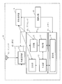
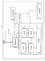
- FIG. 1 is a configuration diagram of a node device 10 according to Embodiment 1.
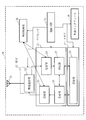
- FIG. 1 is a configuration diagram of a termination device 20 according to Embodiment 1.
- FIG. 4 is a configuration example of a setting request 40 according to the first embodiment. 4 shows a configuration example of a setting response 50 according to the first embodiment.
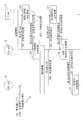
- FIG. 6 is a diagram showing a wireless communication process S100 of a wireless communication method 510 and a wireless communication program 520 in the wireless communication system 500 according to the first embodiment.
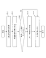
- FIG. 5 is a flowchart of termination time zone determination processing S31 by the termination device 20 according to the first embodiment.
- FIG. 6 is a flowchart of node time zone determination processing S33 according to the first embodiment.
- FIG. The time zone chart 261 which the termination
- FIG. The time zone chart 161a which the node apparatus 10 (10a_adr) which concerns on Embodiment 1 has memorize
- FIG. 3 is a configuration diagram of a node device 10 according to a modification of the first embodiment.
- Embodiment 1 FIG. *** Explanation of configuration *** The configuration of radio communication system 500 according to the present embodiment will be described using FIG.
- the wireless communication system 500 is a wireless multi-hop network system using TSCH.
- a communication timing allocation method of a wireless multi-hop network system using TSCH will be described.
- the communication timing means a communication time zone.
- Reception timing means a reception time zone
- transmission timing means a transmission time zone.
- the wireless communication system 500 includes a termination device 20 and a node device 10 that transmits a message to the termination device 20 by wireless communication.
- the wireless communication system 500 includes a plurality of node devices 10 and a termination device 20, and has a tree topology.
- the termination device 20 and the plurality of node devices 10 constitute a wireless multi-hop network system. That is, the plurality of node devices 10 include the node device 10 that transmits a message to the termination device 20 via another node device.
- node devices 10 and termination devices 20 are required, and the number shown in FIG. 1 is an example, and the present invention is not limited to this. Each node device 10 has the same function. Each of the node device 10 and the terminal device 20 has individual identification information. The node device 10 will be described as having identification information 10a_adr, 10b_adr, and 10c_adr, respectively, and the termination device 20 will be described as having identification information 20_adr.
- the node device 10 When the node device 10 receives a signal from another node device 10 or the termination device 20, the node device 10 checks whether or not the transfer is necessary, and performs transfer processing when the transfer is necessary. Further, the node device 10 and the terminal device 20 perform time synchronization. It is assumed that the time information held in the terminal device 20 can be synchronized by transferring it to each node device 10.
- the node device 10 is a computer.
- the node device 10 includes hardware such as an antenna 41, an RFIC (Radio Frequency Integrated Circuit) 42, a processor 43, a memory 44, a power supply circuit 45, and a power supply holding unit 18.
- the node device 10 includes a wireless communication unit 12, a transmission unit 13, a reception unit 14, a generation unit 15, a determination unit 17, and a storage unit 16 as functional configurations.
- the functions of the transmission unit 13, the reception unit 14, the generation unit 15, and the determination unit 17 in the node device 10 are referred to as “unit” functions of the node device 10.
- the function of the “unit” of the node device 10 is realized by software.
- the wireless communication unit 12 is realized by the RFIC 42.
- the storage unit 16 is realized by the memory 44.
- the configuration of the termination device 20 is the same as the configuration of the node device 10.
- the terminal device 20 includes an external interface 56 in addition to the configuration of the node device 10.
- termination device 20 is a computer.
- the termination device 20 includes hardware such as an antenna 51, an RFIC 52, a processor 53, a memory 54, a power supply circuit 55, an external interface 56, and a power supply holding unit 28.
- terminus apparatus 20 is provided with the radio
- the functions of the transmission unit 23, the reception unit 24, the generation unit 25, and the determination unit 27 in the termination device 20 are referred to as “unit” functions of the termination device 20.
- the function of the “unit” of the termination device 20 is realized by software.
- the wireless communication unit 22 is realized by the RFIC 52.
- the storage unit 26 is realized by the memory 54.
- the hardware of the node device 10 and the termination device 20 are similar.
- the antenna 51 is common to the antenna 41
- the RFIC 52 is common to the RFIC 42
- the processor 53 is common to the processor 43
- the memory 54 is common to the memory 44.
- the RFICs 42 and 52 have radio signal transmission and reception functions.
- the power supply circuits 45 and 55 supply a battery or an external power supply to the RFICs 42 and 52, the processors 43 and 53, the memories 44 and 54, and the like.
- the external interface 56 provided in the termination device 20 is a communication circuit such as Ethernet (registered trademark) or a signal reception circuit such as GPS (Global Positioning System).
- the node device 10 and the termination device 20 include a receiver and a transmitter as communication devices.
- the communication device may be a communication chip or a NIC (Network Interface Card).
- the communication device functions as a communication unit that communicates data.
- the storage units 16 and 26 are realized by the memories 44 and 54, respectively, but may be realized by a memory and an auxiliary storage device. A method for realizing the storage unit is arbitrary.
- the processors 43 and 53 are connected to other hardware via a signal line, and control these other hardware.
- the processors 43 and 53 are ICs (Integrated Circuits) that perform processing.
- the processors 43 and 53 are CPU (Central Processing Unit).
- the memories 44 and 54 are RAM (Random Access Memory).
- the auxiliary storage device is a ROM (Read Only Memory), a flash memory, or an HDD (Hard Disk Drive).
- the auxiliary storage device stores a program for realizing the function of “unit”.
- a program that realizes the function of “unit” is also referred to as a wireless communication program 520.
- This program is loaded into the memories 44 and 54, read into the processors 43 and 53, and executed by the processors 43 and 53.
- the auxiliary storage device also stores an OS (Operating System). At least a part of the OS is loaded into the memories 44 and 54.
- the processors 43 and 53 execute a program for realizing the function of “unit” while executing the OS.
- the node device 10 and the termination device 20 may each include only one processor 43, 53, or may include a plurality of processors 43, 53.
- a plurality of processors 43 and 53 may execute a program for realizing the function of “unit” in cooperation with each other.
- arrows connecting the respective units and the storage units 16 and 26 indicate that each unit stores the processing results in the storage units 16 and 26, or that each unit receives information from the storage units 16 and 26. Represents reading.
- arrows connecting the respective parts represent the flow of control or data.
- the program for realizing the function of “part” may be stored in a portable recording medium such as a magnetic disk, a flexible disk, an optical disk, a compact disk, a Blu-ray (registered trademark) disk, or a DVD (Digital Versatile Disc).
- a portable recording medium such as a magnetic disk, a flexible disk, an optical disk, a compact disk, a Blu-ray (registered trademark) disk, or a DVD (Digital Versatile Disc).
- a wireless communication program product is a storage medium and a storage device on which a program that realizes the function described as “part” is recorded, and is a computer-readable program regardless of the appearance format. Is what you are loading.
- the message is a radio signal that is transmitted and received by the node device 10 and the termination device 20, that is, a frame.
- a message may be referred to as a frame.
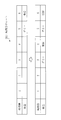
- FIG. 4 is a diagram illustrating a configuration example of the setting request 40 according to the present embodiment.
- the setting request 40 is a message for requesting setting of a transmission time zone in which the node device 10 transmits a message to the terminal device 20.
- the setting request 40 is also called a timing setting request.
- the MAC address or IP address of the node device 10 or the termination device 20 that is the transmission destination is set.
- the MAC address or IP address of the node device 10 or the termination device 20 that is the transmission source is set. Since the destination of the setting request 40 is the terminating device 20 in the global destination 430, the MAC address or IP address of the terminating device 20 is set.
- the global transmission source 440 is set with the MAC address or IP address of the node device 10 that is the transmission source.
- the values of the local destination 410 and the local transmission source 420 are rewritten at every transfer.
- the local destination 410 is the node device 10 (10a_adr)
- the local transmission source 420 is the node device 10 (10b_adr)
- the global destination 430 is the termination device 20 (20_adr)
- the global transmission source 440 is the node device 10 (10b_adr).
- the message type 450 includes information indicating that the setting request 40 is present.
- FIG. 5 is a diagram illustrating a configuration example of the setting response 50 according to the present embodiment.
- the setting response 50 is transmitted to the node device 10 that has transmitted the setting request 40. Therefore, the global destination 430 is set to the node device 10 that transmitted the setting request 40, and the global transmission source 440 is set to the terminating device 20 (20_adr).
- the terminating device 20 starts transmitting the setting response 50. Since the local destination 410 and the local transmission source 420 have already been described, description thereof will be omitted.
- the message type 450 includes information indicating that it is the setting response 50.
- the setting response 50 is a time synchronization response message used for time synchronization between the terminal device 20 and the node device 10. In the response time zone 460, identification information indicating a time zone not currently used by the terminal device 20 is set.
- the radio communication unit 12 transmits / receives a radio signal, that is, a data frame, to / from another node device 10 or the termination device 20 via the antenna 41.
- the generation unit 15 generates a message that needs to be transmitted or transferred to another node device 10 or the termination device 20.
- the generation unit 15 is also referred to as a message generation unit.
- the generation unit 15 receives a message to be transferred from the determination unit 17.
- the generation unit 15 newly generates a message such as time synchronization, terminal authentication, and a measurement value acquired from a sensor (not shown). Further, the generation unit 15 generates a setting request 40. The process for generating the setting request 40 will be described later.
- the transmission unit 13 receives a message that needs to be transmitted to the other node device 10 or the termination device 20 from the generation unit 15 and requests the wireless communication unit 12 to transmit the message.
- the transmission unit 13 performs a calculation such as a transmission time zone by a method such as CSMA-CA or TDMA.
- 802.15.4e TSCH is a communication standard that allows CSMA-CA and TDMA to be mixed by separating time zones.
- the transmission time is determined based on the time supplied from the time holding unit 18.
- a measurement result such as a temperature measured by the generation unit 15 is transmitted once every 30 minutes.
- the time zone for transmitting sensor information is TDMA, and CSMA-CA can be used in other time zones.
- a method of arbitrating a time zone in which each node device 10 transmits a message including sensor information when transmitting by TDMA is shown.
- the receiving unit 14 receives a message transmitted from the other node device 10 or the terminating device 20 to the own device, and notifies the determination unit 17 of the message.
- the receiving unit 14 may correct the absolute time held by the time holding unit 18 based on the timing at which the message is received.
- the storage unit 16 holds the MAC address or IP address of the own node device, and the MAC address or IP address of the other node device 10 or the terminating device 20 of the transmission destination.
- the storage unit 16 may hold a routing table, that is, route information.
- the storage unit 16 manages address information of a parent node device that is a destination of the next hop as a route to the terminal device 20.
- the determination unit 17 analyzes the message received from the reception unit 14 and causes the generation unit 15 to generate a response message. In addition, the determination unit 17 sets and reads a value with the storage unit 16, and transmits a message generation trigger to the generation unit 15.
- the determination unit 17 requests the generation unit 15 to generate a message for transfer. Since the message is transferred toward the global destination 430 of the setting request 40, the message needs to be transmitted toward the local destination 410 serving as a route of the global destination 430. That is, the local destination 410 is replaced with the MAC address or IP address of the parent node device serving as the next hop destination stored in the storage unit 16.
- the transmission unit 13 transmits a message in which the local destination 410 is replaced.
- the determination unit 17 receives the setting response 50 and the setting response 50 is addressed to the own device, that is, when the global destination 430 is the own device, the determination unit 17, based on the response time zone 460 included in the setting response 50, A transmission time zone in which the device transmits a frame is determined. Further, when the setting response 50 is not addressed to the own device, that is, when the global destination 430 is not the own device, the determination unit 17 transmits the transmission time zone in which the own device transmits, and the node device 10 that is a child of the own device. To determine the node reception time zone for receiving messages from the setting response 50 and the setting response 50 is addressed to the own device, that is, when the global destination 430 is the own device, the determination unit 17, based on the response time zone 460 included in the setting response 50, A transmission time zone in which the device transmits a frame is determined. Further, when the setting response 50 is not addressed to the own device, that is, when the global destination 430 is not the own device, the determination unit 17 transmits the transmission time zone
- the time holding unit 18 is a clock circuit composed of a crystal resonator or the like, and is self-running after setting the time and holds the time. It is assumed that the time holding unit 18 can perform time synchronization by notification from GPS or NTP (Network Time Protocol) or the terminal device 20. The time holding unit 18 may perform time synchronization based on the message reception timing, that is, the reception time zone, according to the IEEE 802.15.4e standard.
- each functional unit constituting the termination device 20 is similar to each functional unit constituting the node device 10, and differences will be described below.
- Each element constituting the node device 10 and the termination device 20 includes those that perform the same operation, and are listed as follows. Since the antenna 41 and the antenna 51, the wireless communication unit 12 and the wireless communication unit 22, the transmission unit 13 and the transmission unit 23, and the reception unit 14 and the reception unit 24 have the same configuration, description thereof will be omitted.
- the determination unit 27 determines that the received message is the setting request 40, the determination unit 27 sets the time zone. Specific processing will be described later.
- the generation unit 25 When the generation unit 25 receives the setting request 40, the generation unit 25 generates a setting response 50 using the time zone set by the determination unit 27 and requests the transmission unit 23 to transmit the setting response 50.
- the storage unit 26 in the termination device 20 does not hold the next hop route information to go to the termination device 20. Further, the termination device 20 may hold information on the downlink route from the own device, that is, the downlink route regarding each node device 10 accommodated in the termination device 20.
- the time holding unit 28 can set the time supplied from an NTP server or the like via the external interface 56.
- FIG. 6 is a diagram showing a wireless communication process 510 in the wireless communication method 510 and the wireless communication program 520 in the wireless communication system 500 according to the present embodiment.
- a method will be described in which, after the node device 10 (10a_adr, 10b_adr) joins the network, the transmission time zone of sensor information is assigned to the termination device 20 using TDMA.
- wireless multi-hop path construction and sensor information transmission time zones are assigned outside the time zone in which TDMA is operated.
- the node device 10 transmits sensor information twice per hour. Specifically, it is assumed that the node device 10 transmits sensor information in a time zone of 00 minutes to 01 minutes per hour and 30 minutes to 31 minutes per hour.
- one hour is divided into six in a time frame of 10 minutes, and the node device 10 transmits sensor information to the terminal device 20 in any of these six time zones.
- the six time zones will be described as time zone 1 to time zone 6, respectively.
- the transmission timings of the node device 10 (10a_adr) and the node device 10 (10b_adr) are the same, and transmission is performed within the allocated time width. Problems such as inability to occur.
- the node device 10 (10a_adr) transmits the sensor information attached to the node device 10 (10a_adr)
- the information from the node device 10 (10b_adr) is received, and this information must be transferred first.
- the information to be transmitted must be kept in the memory. This is not a problem when the number of terminals trying to transmit frames via the node device 10 (10a_adr) is small. However, when the number of terminals increases, the number of frames that are continuously queued by the node device 10 increases, Overflow may occur.
- the wireless communication process S100 includes a setting request process S30, a setting response process S312 (end time zone determination process S31 and setting response transmission process S32), a node time zone determination process S33, and a relay node time zone setting process S34. .
- the node device 10 (10a_adr) transmits a setting request 40 for requesting setting of the transmission time zone 101 in which the node device 10 (10a_adr) transmits a message to the terminal device 20.
- the time zone for transmitting the sensor information is in an undecided state, and therefore the node device 10 (10a_adr) transmits the setting request 40 to the terminal device 20.
- the terminal device 20 determines a terminal reception time zone 102 for receiving a message from the node device 10 (10a_adr) (terminal time zone determination processing S31). Specifically, the termination device 20 searches for a time that the termination device 20 is not using to receive a message, that is, an unused time zone. Then, the termination device 20 transmits the setting response 50 including the termination reception time zone 102 as the response time zone 460 to the node device 10 (10a_adr) (setting response transmission processing S32).
- FIG. 6 shows that the terminal device 20 notifies the time zone 6 as an unused time zone.
- the node device 10 (10a_adr) when receiving the setting response 50, stores the response time zone 460 included in the setting response 50 in the storage unit 16 as the transmission time zone 101. That is, the node device 10 (10a_adr) determines a time zone for transmitting sensor information based on the information of the time zone 6 included in the notified response time zone 460.
- the node device 10 (10b_adr) transmits the setting request 40 to the terminal device 20 in the setting request process S30.
- the setting request 40 transmitted from the node device 10 (10b_adr) is transmitted to the termination device 20 via the node device 10 (10a_adr).
- the termination device 20 searches for a time zone that is not used by the termination device 20 for frame reception, that is, an unused time zone.
- the setting response process S32 the terminating device 20 returns a setting response 50. At this time, the terminal device 20 notifies the time zone 4 indicating the unused time zone.
- each node device 10 of the plurality of node devices determines whether or not the setting response 50 is a response to the setting request 40 transmitted from the own device. .
- Each node device 10 of the plurality of node devices determines a time zone for receiving a message as the node reception time zone 103 when the setting response 50 is not a response to the setting request 40 transmitted from the own device.
- Each node device 10 of the plurality of node devices rewrites the response time zone 460 included in the setting response 50 to the node reception time zone 103, and transmits the setting response 50 in which the response time zone 460 is rewritten.
- the node device 10 (10a_adr) operates as a relay terminal from the node device 10 (10b_adr) that is the transmission source of the setting request 40. Therefore, the node device 10 (10a_adr) includes a transmission time zone 101 in which the node device 10 (10a_adr), which is its own device, transmits to the termination device 20, and a node reception time zone 103 in which a frame is received from the node device 10 (10b_adr). Determine both.
- the transmission time zone 101 transmitted from the node device 10 (10a_adr) to the termination device 20 is determined as the time zone 4
- the node reception time zone 103 receiving the frame from the node device 10 (10b_adr) is determined as the time zone 3.
- the setting response 50 is returned to the node device 10 (10b_adr).
- the response time zone 460 set in the set response 50 is the time zone 3 that is the node reception time zone 103 determined by the node device 10 (10a_adr).
- the node device 10 (10b_adr) transmits its sensor information in the time zone 3 that is the response time zone 460 notified by the setting response 50.
- the transmission time zone 101 is determined.
- FIG. 10 is a time zone chart 261 stored in the storage unit 26 by the terminal device 20.
- a terminal reception time zone 102 and a dummy time zone 104 are set.
- the termination device 20 searches for an unused time zone from the time zone chart 261, and executes a termination time zone determination process S31 for determining the search result as the termination reception time zone 102.
- the determination unit 27 searches for an unused time zone in the upper time zone chart 261 of FIG. In the upper time zone chart 261 in FIG. 10, all the time zones are unused.
- the determination unit 27 determines the latest time zone 6 among the unused time zones in the time zone chart 261 as the termination reception time zone 102 in which the termination device 20 receives. The determination unit 27 sets the time zone 6 as the termination reception time zone 102 as shown in the time zone chart 261 in the lower part of FIG.
- step S 313 when the determination unit 27 receives the setting request 40, the determination unit 27 determines the end reception time zone 102 and sets a time zone adjacent to the end reception time zone 102 and before the end reception time zone 102 as a dummy.
- the time zone 104 is determined. As shown in the time zone chart in the lower part of FIG. 10, the time zone 5 that is the time zone immediately before the time zone 6 is set as the dummy time zone 104.
- the generation unit 25 generates a setting response 50 with the response time zone 460 as the time zone 6 and requests the transmission unit 23 to transmit.
- the transmission unit 23 of the termination device 20 transmits the setting response 50 in which the time zone 6 is set as the response time zone 460 via the wireless communication unit 22 and the antenna 51.
- the dummy time zone 104 is not notified to the node device 10, but is set as a flag for excluding from the candidates for the terminal reception time zone 102.
- FIG. 11 is a time zone chart 161a stored in the storage unit 16 by the node device 10 (10a_adr).
- the node time zone determination processing S33 is processing for determining the transmission time zone 101 of the own device when the node device 10 (10a_adr) receives the setting response 50. Since the node device 10 (10a_adr) is the transmission source of the setting request 40 this time, the node device 10 (10a_adr) executes the node time zone determination process S33.
- step S331 the determination unit 17 of the node device 10 (10a_adr) determines the time zone 6 notified by the setting response 50 as the transmission time zone 101. That is, the determination unit 17 of the node device 10 (10a_adr) determines to transmit the sensor information in the time zone 6.
- the determination unit 17 sets the time zone 6 as the transmission time zone 101 as shown in the time zone chart 161a in the lower part of FIG.
- the above description shows the operation when the terminal device 20 and the node device 10 that transmits the setting request 40 are adjacent to each other.
- the node device 10 transmits the setting request 40 and is relayed by one or more node devices 10 will be described.
- the time zone chart 261 of the termination device 20 is in the state of FIG. 12 in which the node device 10 (10a_adr) has already assigned the time zone.
- the node device 10 (10b_adr) transmits the setting request 40.
- the setting request 40 is transferred by the node device 10 (10a_adr) and received by the termination device 20.
- the termination device time zone determination processing S31 described above is performed.
- the termination device 20 receives the setting request from the node device 10 (10a_adr) after the setting request 40 from the node device 10 (10a_adr). In this way, when receiving the setting request 40 after the setting request 40, the terminating device 20 determines a time zone for receiving a message from other than the terminating reception time zone 102 set in the time zone chart 261.
- the termination device 20 determines a time zone for receiving a message from other than the termination reception time zone 102 and other than the dummy time zone 104. As shown in FIG. 12, the terminating device 20 selects a time zone 4 that is neither a reception time zone nor a dummy time zone, and sets the time zone 3 as a dummy time zone. Then, the terminal device 20 includes the time zone 4 as the response time zone 460 in the setting response 50 for the setting request received after the setting request 40. That is, the termination device 20 transmits a setting response 50 with the time zone 4 as the reception time zone to the node device 10 (10a_adr).
- the node device 10 (10a_adr) When the node device 10 (10a_adr) receives the setting response 50, the node device 10 (10a_adr) performs the operation of the relay node time zone setting process S34.
- the relay node time zone setting process S34 will be described.
- FIG. 13 is a time zone chart 161a stored in the storage unit 16 by the node device 10 (10a_adr).
- the determination unit 17 of the node device 10 (10a_adr) determines the transmission time zone 101 based on the response time zone 460 included in the notified setting response 50. As illustrated in the lower part of FIG. 13, the determination unit 17 determines to perform transmission in the time period 4 notified by the setting response 50, and uses the time period 4 of the time period chart 161 a illustrated in the lower part of FIG. 13 as the transmission time period. 101 is set.
- step S342 the determination unit 17 of the node device 10 (10a_adr) determines whether the setting response 50 is a response to the setting request 40 transmitted from the own device based on the global destination 430 of the setting response 50. .
- the determination unit 17 of the node device 10 (10a_adr) determines the time zone for receiving a message for transfer as the node reception time zone 103 when the setting response 50 is not a response to the setting request 40 transmitted from the own device. To do. Whether or not the setting response 50 is transmitted from the own device is determined based on whether or not the global destination 430 of the setting response 50 is the own device.
- the determination unit 17 of the node device 10 (10a_adr) determines the node reception time zone 103 based on the determined transmission time zone 101. As illustrated in the lower part of FIG. 13, the determination unit 17 determines that reception is performed in the time period 3 immediately before the transmission time period 101, and the time period 3 in the time period chart 161 a illustrated in the lower part of FIG. The reception time zone 103 is set.
- step S343 the generation unit 15 of the node device 10 (10a_adr) rewrites the response time zone 460 included in the setting response 50 to the node reception time zone 103, and transmits the setting response 50 in which the response time zone 460 is rewritten. Specifically, the generation unit 15 generates a setting response 50 in which the response time zone 460 is the time zone 3 and requests the transmission unit 13 to transmit.
- the transmission unit 13 of the node device 10 (10a_adr) transmits the setting response 50 in which the time zone 3 is set as the response time zone 460 via the wireless communication unit 12 and the antenna 41. .
- FIG. 14 is a time zone chart 161b stored in the storage unit 16 by the node device 10 (10b_adr).
- the node device 10 (10b_adr) executes the above-described node time zone determination process S33, determines that transmission is performed in the time zone 3 received by the setting response 50, and the time of the time zone chart 161b shown in the lower part of FIG. Band 3 is set as a transmission time band 101.
- the function of each “unit” of the node device 10 and the termination device 20 is realized by software.
- the function of each “unit” of the node device 10 and the termination device 20 is hardware. It may be realized by hardware.
- the configuration of the node device 10 and the termination device 20 according to a modification of the present embodiment will be described with reference to FIGS. 15 and 16.
- the node device 10 and the termination device 20 may include processing circuits 49 and 59.
- the processing circuits 49 and 59 are dedicated electronic circuits for realizing the above-described “unit” function and the storage units 16 and 26.
- the processing circuits 49 and 59 are a single circuit, a composite circuit, a programmed processor, a processor programmed in parallel, a logic IC, a GA (Gate Array), an ASIC (Application Specific Integrated Circuit), or an FPGA. (Field-Programmable Gate Array).
- each “unit” of each of the node device 10 and the terminal device 20 and the storage units 16 and 26 may be realized by a single processing circuit 49 or 59, or may be realized by being distributed to a plurality of processing circuits 49 and 59. May be.
- the functions of the node device 10 and the termination device 20 may be realized by a combination of software and hardware. That is, some functions of each of the node device 10 and the termination device 20 may be realized by dedicated hardware, and the remaining functions may be realized by software.
- the processors 43 and 53, the memories 44 and 54, and the processing circuits 49 and 59 are collectively referred to as a “processing circuit”. That is, regardless of the configuration of each of the node device 10 and the termination device 20 shown in FIGS. 2, 3, 15, and 16, the function of the “unit” and the storage units 16 and 26 are processed. Realized by circuit.
- Part may be read as “Process”, “Procedure” or “Process”. Further, the function of “unit” may be realized by firmware.
- the time zone for message transmission / reception is negotiated between the terminal device and each node device of the plurality of node devices in the terminal device and the plurality of node devices constituting the wireless multi-hop network system.
- the negotiation method is explained.
- the transmission time zone of each node device, the reception time zone and the transmission time zone of the node device that performs transfer, and the termination device receive data. By mediating the reception time zone, it is possible to prevent data from staying in the transferring node device.
- the wireless communication system it is possible to arbitrate between the transmission time zone (transmission timing) and the reception time zone (reception timing) between the node device 10 and the termination device 20. .
- the node device 10 (10b_adr) transfers data, it is necessary to transfer a message in the node device 10 (10a_adr). Since the message transfer is performed in the adjacent time zone, the message residence time in the node device 10 (10a_adr) can be minimized. Therefore, even if the queue length required for the node device 10 is reduced, it is possible to minimize the decrease in the data collection rate due to the message queue overflow.
- Embodiment 2 FIG. In the present embodiment, differences from the first embodiment will be mainly described. In this embodiment, the description of the same structure as that described in Embodiment 1 is omitted. The configurations of the node device 10 and the termination device 20 are the same as those in the first embodiment.
- the terminal device 20 uses the time zone adjacent to the time zone determined as the terminal reception time zone 102 as the dummy time zone 104, and the dummy time zone 104 receives the setting request from the other terminal to the terminal device 20. Control that was not used sometimes was carried out.
- the time zone 3 adjacent to the time zone 4 in FIG. 12 determined by the termination device 20 as the termination reception time zone 102 is the dummy time zone 104.
- the node device 10 that has transmitted the setting request 40 and the terminal device 20 that has received the setting request 40 are adjacent to each other, that is, when no transfer is performed by another node device 10.
- the time zone 104 is not set.
- the terminating device 20 determines whether the setting request 40 is transmitted from the adjacent node device 10x adjacent to the terminating device 20 among the plurality of node devices 10. .
- the termination device 20 sets a time zone adjacent to the termination reception time zone 102 and before the termination reception time zone 102 as the dummy time zone 104. decide.
- the terminal device 20 does not determine the dummy time zone 104 when the setting request 40 is transmitted from the adjacent node device 10x.
- FIG. 17 is a flowchart of the termination time zone determination process S31a in the present embodiment.
- FIG. 17 shows an operation when the terminating device 20 receives the setting request 40 in the present embodiment.
- step S311, step S312, step S313, and step S314 are the same as those described in the first embodiment, and thus description thereof is omitted.
- step S315 the determination unit 27 of the termination device 20 determines whether or not the received setting request 40 is transmitted from the adjacent node device 10x that is the adjacent node device 10. If it is determined that the termination device 20 has received the setting request 40 from the node device 10 (10a_adr) that is adjacent to the termination device 20 (YES in step S315), the determination unit 27 does not set the dummy time zone 104. In the case of NO in step S315, the determination unit 27 proceeds to step S313 and sets the dummy time zone 104. Specifically, the determination unit 27 determines whether the global transmission source 440 and the local transmission source 420 included in the setting request 40 from the node device 10 (10a_adr) match.
- the determination unit 27 determines whether or not the transmission is from the adjacent node device 10x based on the information of the routing table stored in the storage unit 26, or the number of transfers (not shown) included in the setting request 40. May be.
- FIG. 18 is a diagram illustrating time zones of the respective devices determined by the series of processes in FIG. 6 according to the first embodiment.
- FIG. 19 is a diagram showing the time zone of each device when the termination time zone determination processing S31a according to the present embodiment is replaced with the termination device time zone determination processing S31 of FIG.
- the idle time in the termination device 20 can be reduced, and therefore the number of node devices 10 accommodated per termination device 20 can be improved. That is, in FIG. 18, the time zone 5 is a dummy time zone in the termination device 20 and is not used in other terminals, but the termination device 20 can receive in the time zone 5 in FIG. 19. Therefore, the time zone in which the node device 10 (10b_adr) transmits and the time zone in which the node device 10 (10a_adr) transmits the frame to be transferred can be set to the time zone 4 and the time zone 5, respectively.
- the idle time in the termination device 20 can be reduced, so that the number of node devices 10 accommodated in the termination device 20 can be improved. .
- the wireless communication system, the terminal device, the node device, the wireless communication method, and the wireless communication program according to the first and second embodiments are useful for wireless communication, particularly when restarting after simultaneous power-off of a plurality of node devices. Useful.
- the functional configurations of the node device 10 and the termination device 20 are arbitrary as long as the functions described in the above embodiments can be realized.
- Each of the node device 10 and the termination device 20 may be configured in any combination or arbitrary functional configuration.
- Embodiment 1 or 2 may be partially implemented.
- these embodiments may be implemented in any combination in whole or in part.
- said embodiment is an essentially preferable illustration, Comprising: It does not intend restrict
Abstract
A node device is provided with: a transmission unit (13) that transmits, to a termination device, a setting request requesting setting of a transmission time zone in which a message is transmitted; a determination unit (17) that, when receiving a setting response including a response time zone, determines whether or not the setting response is a response to the setting request transmitted from the device itself, wherein the determination unit (17), if the setting response is a response to the setting request transmitted from the device itself, stores the response time zone as the transmission time zone in a storage unit (16), and, if the setting response is not a response to the setting request transmitted from the device itself, stores the response time zone as the transmission time zone in the storage unit (16) and determines a time zone in which the message is received as a node reception time zone; and a generation unit (25) that rewrites the response time zone included in the setting response to the node reception time zone and transmits the setting response in which the response time zone has been rewritten.
Description
本発明は、無線マルチホップネットワークシステムを構成する無線通信システム、終端装置、ノード装置、無線通信方法及び無線通信プログラムに関する。
The present invention relates to a wireless communication system, a terminal device, a node device, a wireless communication method, and a wireless communication program that constitute a wireless multi-hop network system.
無線マルチホップネットワークシステムは、端末、終端端末、また終端端末の上位装置などから構成され、終端端末の配下にツリー状に端末を収容するネットワーク構成が一般的である。端末はノード、或いは、ノード装置ともいう。以下、端末をノード装置と称して説明する。また、終端端末は、終端装置ともいう。以下、終端端末を終端装置と称して説明する。
終端装置又は終端装置の上位装置は、複数のノード装置をホッピングさせることによって、各ノード装置からのデータを収集可能である。例えば各ノード装置は、測定したデータを上位のノード装置に送信し、また、下位のノード装置から受信したデータを上位のノード装置に送信することで、終端装置に対してデータを送信する。このような手順により、終端装置又は上位装置は、各ノード装置で測定されたデータを収集する。ノード装置とノード装置との間の通信、或いはノード装置と終端装置との間の通信には、特定小電力無線、IEEE802.15.4規格、IEEE802.15.4e規格といった通信方式が適用される。 A wireless multi-hop network system includes a terminal, a terminal terminal, a host device of the terminal terminal, and the like, and generally has a network configuration in which terminals are accommodated in a tree shape under the terminal terminal. A terminal is also called a node or a node device. Hereinafter, the terminal will be described as a node device. The terminal terminal is also called a terminal device. Hereinafter, the terminal terminal will be described as a terminal device.
The terminal device or a host device of the terminal device can collect data from each node device by hopping a plurality of node devices. For example, each node device transmits the measured data to the upper node device, and transmits data received from the lower node device to the upper node device, thereby transmitting the data to the termination device. By such a procedure, the terminating device or the host device collects data measured by each node device. A communication method such as specific low-power radio, IEEE 802.15.4 standard, IEEE 802.15.4e standard is applied to communication between the node device and the node device, or communication between the node device and the terminal device. .
無線マルチホップネットワークシステムにおいて、特にIEEE802.15.4e規格で規定されるTSCH(Time Slotted Channel Hopping)方式を適用する場合がある。すなわち、TDMA(Time Division Multiple Access)及びCSMA-CA(Carrier Sense Multiple Access-Collision Avoidance)を併用するMAC(Media Access Control)方式を適用する場合である。
TSCH方式のうち、TDMAで動作する時間帯において、ノード装置及び終端装置は、データフレームを送信する時間帯を送信側と受信側とで予めネゴシエーションしておく必要がある。 In a wireless multi-hop network system, a TSCH (Time Slotted Channel Hopping) method defined by the IEEE 802.15.4e standard may be applied. That is, this is a case where a MAC (Media Access Control) method using both TDMA (Time Division Multiple Access) and CSMA-CA (Carrier Sense Multiple Access-Collision Avidence) is applied.
Among the TSCH schemes, the node device and the termination device need to negotiate in advance the time frame for transmitting the data frame between the transmission side and the reception side in the time zone operating in TDMA.
非特許文献1に開示された技術では、端末が送信するデータフレームのタイミングは固定的であり、端末間相互で調停が行われていない。ノード装置から終端装置まで複数の転送(ホップ)を繰り返す無線マルチホップシステムでは、無線マルチホップシステムの子となるノード装置が、終端装置まで送信すべき情報を、自システムのノード装置に送信する。このとき、終端装置まで送信すべき情報は、このノード装置が転送可能な次のタイミングまでこのノード装置の中に保持され続けることになる。つまり、自システムのノード装置における保持時間が長くなる可能性が生じるという課題がある。自システムのノード装置の台数が増加した場合は、自システムのノード装置が保持するデータフレームの数が増加、言い換えればデータフレームの滞留が発生し、キューあふれなどにより転送すべきデータフレームを破棄せざるを得なくなる可能性がある。この結果、無線マルチホップシステムにおけるデータの収集率が低下するという課題が生じる。
In the technology disclosed in Non-Patent Document 1, the timing of data frames transmitted by terminals is fixed, and no arbitration is performed between terminals. In a wireless multi-hop system that repeats a plurality of transfers (hops) from a node device to a terminal device, a node device that is a child of the wireless multi-hop system transmits information to be transmitted to the terminal device to the node device of its own system. At this time, information to be transmitted to the terminal device is continuously held in the node device until the next timing at which the node device can be transferred. That is, there is a problem that the holding time in the node device of the own system may be increased. When the number of node devices in the own system increases, the number of data frames held by the node device in the own system increases.In other words, data frames are retained, and data frames to be transferred are discarded due to queue overflow or the like. There is a possibility of being forced. As a result, there arises a problem that the data collection rate in the wireless multi-hop system decreases.
本発明は、各ノード装置がデータフレームを終端装置に送信する際に、各ノード装置の受信タイミング及び送信タイミングと、終端装置の受信タイミングとの調停を図ることにより、データフレームがノード装置に滞留することを防止することを目的とする。
In the present invention, when each node device transmits a data frame to a terminal device, the data frame stays in the node device by arbitrating between the reception timing and transmission timing of each node device and the reception timing of the terminal device. The purpose is to prevent this.
本発明に係る無線通信システムは、
終端装置と、前記終端装置に対して無線通信によりメッセージを送信するノード装置とを備えた無線通信システムにおいて、
前記ノード装置は、
前記メッセージを送信する送信時間帯の設定を要求する設定要求を前記終端装置に送信し、
前記終端装置は、
前記設定要求を受信すると、前記ノード装置から前記メッセージを受信する終端受信時間帯を決定し、前記終端受信時間帯を応答時間帯として含む設定応答を前記ノード装置に送信し、
前記ノード装置は、
前記設定応答を受信すると、前記設定応答に含まれる前記応答時間帯を前記送信時間帯として記憶部に記憶する。 A wireless communication system according to the present invention includes:
In a wireless communication system comprising a termination device and a node device that transmits a message to the termination device by wireless communication,
The node device is
Sending a setting request for requesting setting of a transmission time zone for transmitting the message to the terminating device,
The terminator is
When the setting request is received, a terminal reception time zone for receiving the message from the node device is determined, and a setting response including the terminal reception time zone as a response time zone is transmitted to the node device,
The node device is
When the setting response is received, the response time zone included in the setting response is stored in the storage unit as the transmission time zone.
本発明に係る無線通信装置によれば、ノード装置が、メッセージを送信する送信時間帯の設定を要求する設定要求を終端装置に送信する。終端装置は、設定要求を受信すると、ノード装置からメッセージを受信する終端受信時間帯を決定し、終端受信時間帯を応答時間帯として含む設定応答をノード装置に送信する。ノード装置は、設定応答を受信すると、設定応答に含まれる応答時間帯を送信時間帯として記憶部に記憶する。よって、終端装置の受信タイミングである終端受信時間帯と、各ノード装置の送信タイミングである送信時間帯との調停を図ることができ、メッセージがノード装置に滞留することを防止することができる。
According to the wireless communication device of the present invention, the node device transmits a setting request for requesting setting of a transmission time zone for transmitting a message to the terminating device. When receiving the setting request, the termination device determines a termination reception time zone for receiving a message from the node device, and transmits a setting response including the termination reception time zone as a response time zone to the node device. When receiving the setting response, the node device stores the response time zone included in the setting response as a transmission time zone in the storage unit. Therefore, it is possible to achieve arbitration between the termination reception time zone that is the reception timing of the termination device and the transmission time zone that is the transmission timing of each node device, and it is possible to prevent messages from staying in the node device.
実施の形態1.
***構成の説明***
図1を用いて、本実施の形態に係る無線通信システム500の構成について説明する。
無線通信システム500は、TSCHを用いた無線マルチホップネットワークシステムである。本実施の形態では、TSCHを用いた無線マルチホップネットワークシステムの通信タイミングの割り当て方式について説明する。
なお、通信タイミングとは、通信する時間帯を意味する。受信タイミングは受信する時間帯、送信タイミングは送信する時間帯を意味する。Embodiment 1 FIG.
*** Explanation of configuration ***
The configuration of radio communication system 500 according to the present embodiment will be described using FIG.
The wireless communication system 500 is a wireless multi-hop network system using TSCH. In this embodiment, a communication timing allocation method of a wireless multi-hop network system using TSCH will be described.
Note that the communication timing means a communication time zone. Reception timing means a reception time zone, and transmission timing means a transmission time zone.
***構成の説明***
図1を用いて、本実施の形態に係る無線通信システム500の構成について説明する。
無線通信システム500は、TSCHを用いた無線マルチホップネットワークシステムである。本実施の形態では、TSCHを用いた無線マルチホップネットワークシステムの通信タイミングの割り当て方式について説明する。
なお、通信タイミングとは、通信する時間帯を意味する。受信タイミングは受信する時間帯、送信タイミングは送信する時間帯を意味する。
*** Explanation of configuration ***
The configuration of radio communication system 500 according to the present embodiment will be described using FIG.
The wireless communication system 500 is a wireless multi-hop network system using TSCH. In this embodiment, a communication timing allocation method of a wireless multi-hop network system using TSCH will be described.
Note that the communication timing means a communication time zone. Reception timing means a reception time zone, and transmission timing means a transmission time zone.
無線通信システム500は、終端装置20と、終端装置20に対して無線通信によりメッセージを送信するノード装置10とを備える。無線通信システム500は、複数のノード装置10と、終端装置20より構成され、ツリー状トポロジを有する。無線通信システム500は、終端装置20と複数のノード装置10とにより無線マルチホップネットワークシステムを構成する。すなわち、複数のノード装置10は、他のノード装置を介してメッセージを終端装置20に送信するノード装置10を含んでいる。
The wireless communication system 500 includes a termination device 20 and a node device 10 that transmits a message to the termination device 20 by wireless communication. The wireless communication system 500 includes a plurality of node devices 10 and a termination device 20, and has a tree topology. In the wireless communication system 500, the termination device 20 and the plurality of node devices 10 constitute a wireless multi-hop network system. That is, the plurality of node devices 10 include the node device 10 that transmits a message to the termination device 20 via another node device.
なお、ノード装置10と終端装置20とは、各々1台以上あればよく、図1に記載した台数は一例であって、これに限定するものではない。各ノード装置10は同じ機能を有する。ノード装置10と終端装置20とはそれぞれ個別の識別情報を有している。ノード装置10については、それぞれ、識別情報10a_adr,10b_adr,10c_adrを有しており、終端装置20については識別情報20_adrを有しているとして説明を行う。
It should be noted that one or more node devices 10 and termination devices 20 are required, and the number shown in FIG. 1 is an example, and the present invention is not limited to this. Each node device 10 has the same function. Each of the node device 10 and the terminal device 20 has individual identification information. The node device 10 will be described as having identification information 10a_adr, 10b_adr, and 10c_adr, respectively, and the termination device 20 will be described as having identification information 20_adr.
ノード装置10は、他のノード装置10又は終端装置20から信号を受信した場合、転送する必要があるかどうかを確認し、転送が必要な場合には転送処理を行う。また、ノード装置10と終端装置20とは時刻同期を行う。終端装置20に保持した時刻情報を、各ノード装置10に転送することにより同期することが可能であるとする。
When the node device 10 receives a signal from another node device 10 or the termination device 20, the node device 10 checks whether or not the transfer is necessary, and performs transfer processing when the transfer is necessary. Further, the node device 10 and the terminal device 20 perform time synchronization. It is assumed that the time information held in the terminal device 20 can be synchronized by transferring it to each node device 10.
図2を用いて、本実施の形態に係るノード装置10の構成について説明する。
本実施の形態において、ノード装置10は、コンピュータである。ノード装置10は、アンテナ41、RFIC(Radio Frequency Integrated Circuit)42、プロセッサ43、メモリ44、電源回路45、電源保持部18といったハードウェアを備える。
また、ノード装置10は、機能構成として、無線通信部12と、送信部13と、受信部14と、生成部15と、判定部17と、記憶部16とを備える。以下の説明では、ノード装置10における送信部13と、受信部14と、生成部15と、判定部17との機能を、ノード装置10の「部」の機能という。ノード装置10の「部」の機能は、ソフトウェアで実現される。また、無線通信部12はRFIC42により実現される。また、記憶部16は、メモリ44により実現される。 The configuration of thenode device 10 according to the present embodiment will be described with reference to FIG.
In the present embodiment, thenode device 10 is a computer. The node device 10 includes hardware such as an antenna 41, an RFIC (Radio Frequency Integrated Circuit) 42, a processor 43, a memory 44, a power supply circuit 45, and a power supply holding unit 18.
Further, thenode device 10 includes a wireless communication unit 12, a transmission unit 13, a reception unit 14, a generation unit 15, a determination unit 17, and a storage unit 16 as functional configurations. In the following description, the functions of the transmission unit 13, the reception unit 14, the generation unit 15, and the determination unit 17 in the node device 10 are referred to as “unit” functions of the node device 10. The function of the “unit” of the node device 10 is realized by software. The wireless communication unit 12 is realized by the RFIC 42. The storage unit 16 is realized by the memory 44.
本実施の形態において、ノード装置10は、コンピュータである。ノード装置10は、アンテナ41、RFIC(Radio Frequency Integrated Circuit)42、プロセッサ43、メモリ44、電源回路45、電源保持部18といったハードウェアを備える。
また、ノード装置10は、機能構成として、無線通信部12と、送信部13と、受信部14と、生成部15と、判定部17と、記憶部16とを備える。以下の説明では、ノード装置10における送信部13と、受信部14と、生成部15と、判定部17との機能を、ノード装置10の「部」の機能という。ノード装置10の「部」の機能は、ソフトウェアで実現される。また、無線通信部12はRFIC42により実現される。また、記憶部16は、メモリ44により実現される。 The configuration of the
In the present embodiment, the
Further, the
図3を用いて、本実施の形態に係る終端装置20の構成について説明する。終端装置20の構成はノード装置10の構成と同様である。終端装置20は、ノード装置10の構成に加え、外部インタフェース56を備える。
本実施の形態において、終端装置20は、コンピュータである。終端装置20は、アンテナ51、RFIC52、プロセッサ53、メモリ54、電源回路55、外部インタフェース56、電源保持部28といったハードウェアを備える。
また、終端装置20は、機能構成として、無線通信部22と、送信部23と、受信部24と、生成部25と、判定部27と、記憶部26とを備える。以下の説明では、終端装置20における送信部23と、受信部24と、生成部25と、判定部27との機能を、終端装置20の「部」の機能という。終端装置20の「部」の機能は、ソフトウェアで実現される。また、無線通信部22はRFIC52により実現される。また、記憶部26は、メモリ54により実現される。 With reference to FIG. 3, the configuration oftermination apparatus 20 according to the present embodiment will be described. The configuration of the termination device 20 is the same as the configuration of the node device 10. The terminal device 20 includes an external interface 56 in addition to the configuration of the node device 10.
In the present embodiment,termination device 20 is a computer. The termination device 20 includes hardware such as an antenna 51, an RFIC 52, a processor 53, a memory 54, a power supply circuit 55, an external interface 56, and a power supply holding unit 28.
Moreover, the termination |terminus apparatus 20 is provided with the radio | wireless communication part 22, the transmission part 23, the receiving part 24, the production | generation part 25, the determination part 27, and the memory | storage part 26 as a function structure. In the following description, the functions of the transmission unit 23, the reception unit 24, the generation unit 25, and the determination unit 27 in the termination device 20 are referred to as “unit” functions of the termination device 20. The function of the “unit” of the termination device 20 is realized by software. The wireless communication unit 22 is realized by the RFIC 52. The storage unit 26 is realized by the memory 54.
本実施の形態において、終端装置20は、コンピュータである。終端装置20は、アンテナ51、RFIC52、プロセッサ53、メモリ54、電源回路55、外部インタフェース56、電源保持部28といったハードウェアを備える。
また、終端装置20は、機能構成として、無線通信部22と、送信部23と、受信部24と、生成部25と、判定部27と、記憶部26とを備える。以下の説明では、終端装置20における送信部23と、受信部24と、生成部25と、判定部27との機能を、終端装置20の「部」の機能という。終端装置20の「部」の機能は、ソフトウェアで実現される。また、無線通信部22はRFIC52により実現される。また、記憶部26は、メモリ54により実現される。 With reference to FIG. 3, the configuration of
In the present embodiment,
Moreover, the termination |
ノード装置10と終端装置20とのハードウェアは類似している。アンテナ51は、アンテナ41と、RFIC52は、RFIC42と、プロセッサ53は、プロセッサ43と、メモリ54は、メモリ44と、それぞれ共通である。
RFIC42,52は無線信号の送信及び受信機能を有する。電源回路45,55は、電池又は外部電源をRFIC42,52、プロセッサ43,53、メモリ44,54などに供給する。終端装置20が備える外部インタフェース56は、Ethernet(登録商標)等の通信回路、或いはGPS(Global Positioning System)等の信号受信回路である。
ノード装置10と終端装置20とは、通信装置としてレシーバとトランスミッタとを備える。具体的には、通信装置は、通信チップ又はNIC(Network Interface Card)でもよい。通信装置はデータを通信する通信部として機能する。 The hardware of thenode device 10 and the termination device 20 are similar. The antenna 51 is common to the antenna 41, the RFIC 52 is common to the RFIC 42, the processor 53 is common to the processor 43, and the memory 54 is common to the memory 44.
The RFICs 42 and 52 have radio signal transmission and reception functions. The power supply circuits 45 and 55 supply a battery or an external power supply to the RFICs 42 and 52, the processors 43 and 53, the memories 44 and 54, and the like. The external interface 56 provided in the termination device 20 is a communication circuit such as Ethernet (registered trademark) or a signal reception circuit such as GPS (Global Positioning System).
Thenode device 10 and the termination device 20 include a receiver and a transmitter as communication devices. Specifically, the communication device may be a communication chip or a NIC (Network Interface Card). The communication device functions as a communication unit that communicates data.
RFIC42,52は無線信号の送信及び受信機能を有する。電源回路45,55は、電池又は外部電源をRFIC42,52、プロセッサ43,53、メモリ44,54などに供給する。終端装置20が備える外部インタフェース56は、Ethernet(登録商標)等の通信回路、或いはGPS(Global Positioning System)等の信号受信回路である。
ノード装置10と終端装置20とは、通信装置としてレシーバとトランスミッタとを備える。具体的には、通信装置は、通信チップ又はNIC(Network Interface Card)でもよい。通信装置はデータを通信する通信部として機能する。 The hardware of the
The
The
また、記憶部16,26は、各々メモリ44,54により実現されるとしたがメモリ及び補助記憶装置により実現されていてもよい。記憶部の実現方法は任意である。
The storage units 16 and 26 are realized by the memories 44 and 54, respectively, but may be realized by a memory and an auxiliary storage device. A method for realizing the storage unit is arbitrary.
プロセッサ43,53は、信号線を介して他のハードウェアと接続され、これら他のハードウェアを制御する。
プロセッサ43,53は、プロセッシングを行うIC(Integrated Circuit)である。プロセッサ43,53は、CPU(Central Processing Unit)である。 The processors 43 and 53 are connected to other hardware via a signal line, and control these other hardware.
The processors 43 and 53 are ICs (Integrated Circuits) that perform processing. The processors 43 and 53 are CPU (Central Processing Unit).
メモリ44,54は、具体的には、RAM(Random Access Memory)である。補助記憶装置は、具体的には、ROM(Read Only Memory)、フラッシュメモリ、又は、HDD(Hard Disk Drive)である。
Specifically, the memories 44 and 54 are RAM (Random Access Memory). Specifically, the auxiliary storage device is a ROM (Read Only Memory), a flash memory, or an HDD (Hard Disk Drive).
図示はないが、補助記憶装置には、「部」の機能を実現するプログラムが記憶されている。「部」の機能を実現するプログラムを無線通信プログラム520ともいう。このプログラムは、メモリ44,54にロードされ、プロセッサ43,53に読み込まれ、プロセッサ43,53によって実行される。また、補助記憶装置には、OS(Operating System)も記憶されている。OSの少なくとも一部がメモリ44,54にロードされる。プロセッサ43,53はOSを実行しながら、「部」の機能を実現するプログラムを実行する。
Although not shown, the auxiliary storage device stores a program for realizing the function of “unit”. A program that realizes the function of “unit” is also referred to as a wireless communication program 520. This program is loaded into the memories 44 and 54, read into the processors 43 and 53, and executed by the processors 43 and 53. The auxiliary storage device also stores an OS (Operating System). At least a part of the OS is loaded into the memories 44 and 54. The processors 43 and 53 execute a program for realizing the function of “unit” while executing the OS.
ノード装置10及び終端装置20は、各々1つのプロセッサ43,53のみを備えていてもよいし、複数のプロセッサ43,53を備えていてもよい。複数のプロセッサ43,53が「部」の機能を実現するプログラムを連携して実行してもよい。
The node device 10 and the termination device 20 may each include only one processor 43, 53, or may include a plurality of processors 43, 53. A plurality of processors 43 and 53 may execute a program for realizing the function of “unit” in cooperation with each other.
「部」の処理の結果を示す情報、データ、信号値、及び、変数値は、補助記憶装置、メモリ44,54、又は、プロセッサ43,53内のレジスタ又はキャッシュメモリに記憶される。
なお、図2及び図3において、各部と記憶部16,26とを結ぶ矢印は、各部が処理の結果を記憶部16,26に記憶すること、或いは、各部が記憶部16,26から情報を読み出すことを表している。また、各部を結ぶ矢印は、制御或いはデータの流れを表している。 Information, data, signal values, and variable values indicating the result of the processing of “part” are stored in the auxiliary storage device, the memories 44 and 54, or the registers or cache memories in the processors 43 and 53.
2 and 3, the arrows connecting the respective units and the storage units 16 and 26 indicate that each unit stores the processing results in the storage units 16 and 26, or that each unit receives information from the storage units 16 and 26. Represents reading. In addition, arrows connecting the respective parts represent the flow of control or data.
なお、図2及び図3において、各部と記憶部16,26とを結ぶ矢印は、各部が処理の結果を記憶部16,26に記憶すること、或いは、各部が記憶部16,26から情報を読み出すことを表している。また、各部を結ぶ矢印は、制御或いはデータの流れを表している。 Information, data, signal values, and variable values indicating the result of the processing of “part” are stored in the auxiliary storage device, the memories 44 and 54, or the registers or cache memories in the processors 43 and 53.
2 and 3, the arrows connecting the respective units and the
「部」の機能を実現するプログラムは、磁気ディスク、フレキシブルディスク、光ディスク、コンパクトディスク、ブルーレイ(登録商標)ディスク、DVD(Digital Versatile Disc)といった可搬記録媒体に記憶されてもよい。
なお、無線通信プログラムプロダクトと称されるものは、「部」として説明している機能を実現するプログラムが記録された記憶媒体及び記憶装置であり、見た目の形式に関わらず、コンピュータ読み取り可能なプログラムをロードしているものである。 The program for realizing the function of “part” may be stored in a portable recording medium such as a magnetic disk, a flexible disk, an optical disk, a compact disk, a Blu-ray (registered trademark) disk, or a DVD (Digital Versatile Disc).
Note that what is referred to as a wireless communication program product is a storage medium and a storage device on which a program that realizes the function described as “part” is recorded, and is a computer-readable program regardless of the appearance format. Is what you are loading.
***メッセージの構成の説明***
まず、ノード装置10及び終端装置20が送受信するメッセージの構成について説明する。メッセージは、ノード装置10及び終端装置20が送受信する無線信号、すなわちフレームである。以下の説明において、メッセージをフレームという場合がある。 *** Explanation of message structure ***
First, the configuration of messages transmitted and received by thenode device 10 and the termination device 20 will be described. The message is a radio signal that is transmitted and received by the node device 10 and the termination device 20, that is, a frame. In the following description, a message may be referred to as a frame.
まず、ノード装置10及び終端装置20が送受信するメッセージの構成について説明する。メッセージは、ノード装置10及び終端装置20が送受信する無線信号、すなわちフレームである。以下の説明において、メッセージをフレームという場合がある。 *** Explanation of message structure ***
First, the configuration of messages transmitted and received by the
図4は、本実施の形態に係る設定要求40の構成例を示す図である。設定要求40は、ノード装置10が終端装置20に対してメッセージを送信する送信時間帯の設定を要求するメッセージである。設定要求40は、タイミング設定要求ともいう。
ローカル宛先410には、送信先となるノード装置10又は終端装置20のMACアドレス又はIPアドレスが設定される。
ローカル送信元420には、送信元となるノード装置10又は終端装置20のMACアドレス又はIPアドレスが設定される。
グローバル宛先430には、設定要求40の宛先が終端装置20であるため、終端装置20のMACアドレス又はIPアドレスが設定される。
グローバル送信元440には、送信元となるノード装置10のMACアドレス又はIPアドレスが設定される。
ローカル宛先410、ローカル送信元420は、転送の度に値が書き換えられる。具体例として、設定要求40をノード装置10(10b_adr)から終端装置20(20_adr)まで送信する場合について説明する。この場合、ローカル宛先410はノード装置10(10a_adr)、ローカル送信元420はノード装置10(10b_adr)、グローバル宛先430は終端装置20(20_adr)、グローバル送信元440はノード装置10(10b_adr)となる。但し、ノード装置10(10a_adr)がこの設定要求40を転送する場合には、グローバル送信元440とグローバル宛先430は不変であるが、ローカル送信元420はノード装置10(10a_adr)に、ローカル宛先410は終端装置20(20_adr)に変更され、転送される。
また、メッセージ種別450には、設定要求40である旨の情報が含まれる。 FIG. 4 is a diagram illustrating a configuration example of the setting request 40 according to the present embodiment. The setting request 40 is a message for requesting setting of a transmission time zone in which thenode device 10 transmits a message to the terminal device 20. The setting request 40 is also called a timing setting request.
In thelocal destination 410, the MAC address or IP address of the node device 10 or the termination device 20 that is the transmission destination is set.
In thelocal transmission source 420, the MAC address or IP address of the node device 10 or the termination device 20 that is the transmission source is set.
Since the destination of the setting request 40 is the terminatingdevice 20 in the global destination 430, the MAC address or IP address of the terminating device 20 is set.
Theglobal transmission source 440 is set with the MAC address or IP address of the node device 10 that is the transmission source.
The values of thelocal destination 410 and the local transmission source 420 are rewritten at every transfer. As a specific example, a case where the setting request 40 is transmitted from the node device 10 (10b_adr) to the terminal device 20 (20_adr) will be described. In this case, the local destination 410 is the node device 10 (10a_adr), the local transmission source 420 is the node device 10 (10b_adr), the global destination 430 is the termination device 20 (20_adr), and the global transmission source 440 is the node device 10 (10b_adr). . However, when the node device 10 (10a_adr) transfers the setting request 40, the global transmission source 440 and the global destination 430 are unchanged, but the local transmission source 420 sends the local destination 410 to the node device 10 (10a_adr). Is changed to the terminating device 20 (20_adr) and transferred.
Themessage type 450 includes information indicating that the setting request 40 is present.
ローカル宛先410には、送信先となるノード装置10又は終端装置20のMACアドレス又はIPアドレスが設定される。
ローカル送信元420には、送信元となるノード装置10又は終端装置20のMACアドレス又はIPアドレスが設定される。
グローバル宛先430には、設定要求40の宛先が終端装置20であるため、終端装置20のMACアドレス又はIPアドレスが設定される。
グローバル送信元440には、送信元となるノード装置10のMACアドレス又はIPアドレスが設定される。
ローカル宛先410、ローカル送信元420は、転送の度に値が書き換えられる。具体例として、設定要求40をノード装置10(10b_adr)から終端装置20(20_adr)まで送信する場合について説明する。この場合、ローカル宛先410はノード装置10(10a_adr)、ローカル送信元420はノード装置10(10b_adr)、グローバル宛先430は終端装置20(20_adr)、グローバル送信元440はノード装置10(10b_adr)となる。但し、ノード装置10(10a_adr)がこの設定要求40を転送する場合には、グローバル送信元440とグローバル宛先430は不変であるが、ローカル送信元420はノード装置10(10a_adr)に、ローカル宛先410は終端装置20(20_adr)に変更され、転送される。
また、メッセージ種別450には、設定要求40である旨の情報が含まれる。 FIG. 4 is a diagram illustrating a configuration example of the setting request 40 according to the present embodiment. The setting request 40 is a message for requesting setting of a transmission time zone in which the
In the
In the
Since the destination of the setting request 40 is the terminating
The
The values of the
The
図5は、本実施の形態に係る設定応答50の構成例を示す図である。設定応答50は、設定応答50は設定要求40を送信したノード装置10に対して送信される。
よって、グローバル宛先430は設定要求40を送信したノード装置10に設定され、グローバル送信元440は終端装置20(20_adr)に設定される。終端装置20が設定応答50の送信を開始する。
ローカル宛先410及びローカル送信元420はすでに説明をした通りであるから、説明を省略する。メッセージ種別450は、設定応答50である旨の情報が含まれる。設定応答50は、終端装置20とノード装置10との時刻同期に用いられる時刻同期応答メッセージである。
応答時間帯460は、終端装置20が現状使用していない時間帯を表す識別情報が設定される。 FIG. 5 is a diagram illustrating a configuration example of the setting response 50 according to the present embodiment. The setting response 50 is transmitted to thenode device 10 that has transmitted the setting request 40.
Therefore, theglobal destination 430 is set to the node device 10 that transmitted the setting request 40, and the global transmission source 440 is set to the terminating device 20 (20_adr). The terminating device 20 starts transmitting the setting response 50.
Since thelocal destination 410 and the local transmission source 420 have already been described, description thereof will be omitted. The message type 450 includes information indicating that it is the setting response 50. The setting response 50 is a time synchronization response message used for time synchronization between the terminal device 20 and the node device 10.
In theresponse time zone 460, identification information indicating a time zone not currently used by the terminal device 20 is set.
よって、グローバル宛先430は設定要求40を送信したノード装置10に設定され、グローバル送信元440は終端装置20(20_adr)に設定される。終端装置20が設定応答50の送信を開始する。
ローカル宛先410及びローカル送信元420はすでに説明をした通りであるから、説明を省略する。メッセージ種別450は、設定応答50である旨の情報が含まれる。設定応答50は、終端装置20とノード装置10との時刻同期に用いられる時刻同期応答メッセージである。
応答時間帯460は、終端装置20が現状使用していない時間帯を表す識別情報が設定される。 FIG. 5 is a diagram illustrating a configuration example of the setting response 50 according to the present embodiment. The setting response 50 is transmitted to the
Therefore, the
Since the
In the
***ノード装置10の機能構成の説明***
ここで、本実施の形態に係るノード装置10の機能構成である各部について説明する。
無線通信部12は、アンテナ41を介して他のノード装置10又は終端装置20との間で無線信号、すなわちデータフレームを送受信する。
生成部15は、他のノード装置10又は終端装置20に送信或いは転送が必要となるメッセージを生成する。生成部15は、メッセージ生成部ともいう。メッセージを転送する場合、生成部15は、判定部17から転送対象となるメッセージを受け取る。また、生成部15では、新たに、時刻同期、端末認証、図示していないがセンサから取得した計測値などのメッセージを生成する。また、生成部15では、設定要求40を生成する。設定要求40を生成する処理については後述する。 *** Explanation of functional configuration ofnode device 10 ***
Here, each part which is a function structure of thenode apparatus 10 which concerns on this Embodiment is demonstrated.
Theradio communication unit 12 transmits / receives a radio signal, that is, a data frame, to / from another node device 10 or the termination device 20 via the antenna 41.
Thegeneration unit 15 generates a message that needs to be transmitted or transferred to another node device 10 or the termination device 20. The generation unit 15 is also referred to as a message generation unit. When transferring a message, the generation unit 15 receives a message to be transferred from the determination unit 17. In addition, the generation unit 15 newly generates a message such as time synchronization, terminal authentication, and a measurement value acquired from a sensor (not shown). Further, the generation unit 15 generates a setting request 40. The process for generating the setting request 40 will be described later.
ここで、本実施の形態に係るノード装置10の機能構成である各部について説明する。
無線通信部12は、アンテナ41を介して他のノード装置10又は終端装置20との間で無線信号、すなわちデータフレームを送受信する。
生成部15は、他のノード装置10又は終端装置20に送信或いは転送が必要となるメッセージを生成する。生成部15は、メッセージ生成部ともいう。メッセージを転送する場合、生成部15は、判定部17から転送対象となるメッセージを受け取る。また、生成部15では、新たに、時刻同期、端末認証、図示していないがセンサから取得した計測値などのメッセージを生成する。また、生成部15では、設定要求40を生成する。設定要求40を生成する処理については後述する。 *** Explanation of functional configuration of
Here, each part which is a function structure of the
The
The
送信部13は、他のノード装置10又は終端装置20に送信が必要となるメッセージを生成部15から受け取り、無線通信部12に送信を依頼する。具体例としては、送信部13は、送信時間帯などの計算をCSMA-CA、或いは、TDMA等の方法によって行う。802.15.4e TSCHは、CSMA-CAとTDMAとを時間帯を切り分けるなどして混在させることを許容する通信規格である。TDMAで送信する場合には、時刻保持部18より供給される時刻に基づき、送信する時刻を確定する。
The transmission unit 13 receives a message that needs to be transmitted to the other node device 10 or the termination device 20 from the generation unit 15 and requests the wireless communication unit 12 to transmit the message. As a specific example, the transmission unit 13 performs a calculation such as a transmission time zone by a method such as CSMA-CA or TDMA. 802.15.4e TSCH is a communication standard that allows CSMA-CA and TDMA to be mixed by separating time zones. When transmitting by TDMA, the transmission time is determined based on the time supplied from the time holding unit 18.
具体例としては、無線通信システム500で想定する無線マルチホップシステムにおいて、生成部15で測定した温度等の計測結果を30分に1回、送信するものとする。この場合、センサ情報を送信する時間帯はTDMAで、それ以外の時間帯においては、CSMA-CAを用いるとすることができる。本実施の形態では、TDMAで送信する場合において、各ノード装置10がセンサ情報を含むメッセージを送信する時間帯を調停する方法を示す。
As a specific example, in a wireless multi-hop system assumed in the wireless communication system 500, a measurement result such as a temperature measured by the generation unit 15 is transmitted once every 30 minutes. In this case, the time zone for transmitting sensor information is TDMA, and CSMA-CA can be used in other time zones. In the present embodiment, a method of arbitrating a time zone in which each node device 10 transmits a message including sensor information when transmitting by TDMA is shown.
受信部14は、他のノード装置10又は終端装置20から自装置宛てに送信されたメッセージを受信し、判定部17に通知する。また、受信部14は、メッセージを受信したタイミングに基づいて、時刻保持部18で保持する絶対時刻を補正するなどしてもよい。
The receiving unit 14 receives a message transmitted from the other node device 10 or the terminating device 20 to the own device, and notifies the determination unit 17 of the message. The receiving unit 14 may correct the absolute time held by the time holding unit 18 based on the timing at which the message is received.
記憶部16は、自ノード装置のMACアドレス或いはIPアドレス、送信先の他のノード装置10又は終端装置20のMACアドレス或いはIPアドレスを保持する。この他に、記憶部16は、ルーティングテーブル、すなわち経路情報を保持してもよい。具体例としては、記憶部16は、終端装置20への経路として次ホップの目的地となる親ノード装置のアドレス情報を管理する。
The storage unit 16 holds the MAC address or IP address of the own node device, and the MAC address or IP address of the other node device 10 or the terminating device 20 of the transmission destination. In addition, the storage unit 16 may hold a routing table, that is, route information. As a specific example, the storage unit 16 manages address information of a parent node device that is a destination of the next hop as a route to the terminal device 20.
判定部17は、受信部14から受信したメッセージを解析し、生成部15に応答のメッセージを生成させる。また、判定部17は、記憶部16との間で値の設定や読み出しを行い、生成部15にメッセージ生成の契機を送信する。
判定部17では、本実施の形態に係るメッセージである設定要求40を受信すると、生成部15に対して転送用のメッセージ生成を依頼する。メッセージは設定要求40のグローバル宛先430に向けて転送されることになるため、グローバル宛先430の経路となる、ローカル宛先410に向けて送信される必要がある。つまり、ローカル宛先410を、記憶部16に保存している次ホップの目的地となる親ノード装置のMACアドレスやIPアドレスに置き換える。送信部13は、ローカル宛先410が置き換えられたメッセージを送信する。
更に、判定部17は、設定応答50を受信した際に、設定応答50が自装置宛て、すなわちグローバル宛先430が自装置である場合には、設定応答50に含む応答時間帯460に基づいて、自装置がフレームを送信する送信時間帯を決定する。また、判定部17は、設定応答50が自装置宛てでない場合、すなわちグローバル宛先430が自装置でない場合には、自装置が送信を行う送信時間帯と、自装置の子となるノード装置10とからメッセージを受信するノード受信時間帯を決定する処理を行う。 Thedetermination unit 17 analyzes the message received from the reception unit 14 and causes the generation unit 15 to generate a response message. In addition, the determination unit 17 sets and reads a value with the storage unit 16, and transmits a message generation trigger to the generation unit 15.
Upon receiving the setting request 40 that is a message according to the present embodiment, thedetermination unit 17 requests the generation unit 15 to generate a message for transfer. Since the message is transferred toward the global destination 430 of the setting request 40, the message needs to be transmitted toward the local destination 410 serving as a route of the global destination 430. That is, the local destination 410 is replaced with the MAC address or IP address of the parent node device serving as the next hop destination stored in the storage unit 16. The transmission unit 13 transmits a message in which the local destination 410 is replaced.
Furthermore, when thedetermination unit 17 receives the setting response 50 and the setting response 50 is addressed to the own device, that is, when the global destination 430 is the own device, the determination unit 17, based on the response time zone 460 included in the setting response 50, A transmission time zone in which the device transmits a frame is determined. Further, when the setting response 50 is not addressed to the own device, that is, when the global destination 430 is not the own device, the determination unit 17 transmits the transmission time zone in which the own device transmits, and the node device 10 that is a child of the own device. To determine the node reception time zone for receiving messages from
判定部17では、本実施の形態に係るメッセージである設定要求40を受信すると、生成部15に対して転送用のメッセージ生成を依頼する。メッセージは設定要求40のグローバル宛先430に向けて転送されることになるため、グローバル宛先430の経路となる、ローカル宛先410に向けて送信される必要がある。つまり、ローカル宛先410を、記憶部16に保存している次ホップの目的地となる親ノード装置のMACアドレスやIPアドレスに置き換える。送信部13は、ローカル宛先410が置き換えられたメッセージを送信する。
更に、判定部17は、設定応答50を受信した際に、設定応答50が自装置宛て、すなわちグローバル宛先430が自装置である場合には、設定応答50に含む応答時間帯460に基づいて、自装置がフレームを送信する送信時間帯を決定する。また、判定部17は、設定応答50が自装置宛てでない場合、すなわちグローバル宛先430が自装置でない場合には、自装置が送信を行う送信時間帯と、自装置の子となるノード装置10とからメッセージを受信するノード受信時間帯を決定する処理を行う。 The
Upon receiving the setting request 40 that is a message according to the present embodiment, the
Furthermore, when the
時刻保持部18は、水晶振動子などから構成されるクロック回路であり、時刻を設定後は自走し、時刻を保持する。時刻保持部18は、GPS或いはNTP(Network Time Protocol)、又は終端装置20からの通知により、時刻同期を行うことができるものとする。また、時刻保持部18は、IEEE 802.15.4e規定により、メッセージの受信タイミング、すなわち受信時間帯に基づく時刻同期を実施してもよい。
The time holding unit 18 is a clock circuit composed of a crystal resonator or the like, and is self-running after setting the time and holds the time. It is assumed that the time holding unit 18 can perform time synchronization by notification from GPS or NTP (Network Time Protocol) or the terminal device 20. The time holding unit 18 may perform time synchronization based on the message reception timing, that is, the reception time zone, according to the IEEE 802.15.4e standard.
***終端装置20の機能構成の説明***
次に、本実施の形態に係る終端装置20の機能構成である各部について説明する。
終端装置20を構成する各機能部は、ノード装置10を構成する各機能部と類似であり、以下では差分について述べる。 *** Explanation of functional configuration oftermination device 20 ***
Next, each part which is a function structure of the termination |terminus apparatus 20 which concerns on this Embodiment is demonstrated.
Each functional unit constituting thetermination device 20 is similar to each functional unit constituting the node device 10, and differences will be described below.
次に、本実施の形態に係る終端装置20の機能構成である各部について説明する。
終端装置20を構成する各機能部は、ノード装置10を構成する各機能部と類似であり、以下では差分について述べる。 *** Explanation of functional configuration of
Next, each part which is a function structure of the termination |
Each functional unit constituting the
ノード装置10と終端装置20とを構成する各要素は同じ動作を行うものが含まれており、以下の通りに列挙する。アンテナ41とアンテナ51、無線通信部12と無線通信部22、送信部13と送信部23、受信部14と受信部24は、それぞれ同様の構成となるため説明を省略する。
Each element constituting the node device 10 and the termination device 20 includes those that perform the same operation, and are listed as follows. Since the antenna 41 and the antenna 51, the wireless communication unit 12 and the wireless communication unit 22, the transmission unit 13 and the transmission unit 23, and the reception unit 14 and the reception unit 24 have the same configuration, description thereof will be omitted.
判定部27は、受信したメッセージが設定要求40であると判断すると、時間帯の設定を実施する。具体的な処理は後述する。
When the determination unit 27 determines that the received message is the setting request 40, the determination unit 27 sets the time zone. Specific processing will be described later.
生成部25は、設定要求40を受信すると、判定部27により設定された時間帯を用いて設定応答50を生成し、送信部23に送信を依頼する。
When the generation unit 25 receives the setting request 40, the generation unit 25 generates a setting response 50 using the time zone set by the determination unit 27 and requests the transmission unit 23 to transmit the setting response 50.
終端装置20における記憶部26は、ノード装置10における記憶部16とは異なって、終端装置20に向かうための次ホップの経路情報は保持しない。また、終端装置20は自装置からの下り経路、すなわち終端装置20に収容されるそれぞれのノード装置10に関する下り経路の情報を保持してもよい。
Unlike the storage unit 16 in the node device 10, the storage unit 26 in the termination device 20 does not hold the next hop route information to go to the termination device 20. Further, the termination device 20 may hold information on the downlink route from the own device, that is, the downlink route regarding each node device 10 accommodated in the termination device 20.
時刻保持部28は、外部インタフェース56を介して、NTPサーバなどから供給された時刻を設定可能とする。
The time holding unit 28 can set the time supplied from an NTP server or the like via the external interface 56.
***動作の説明***
<無線通信処理S100>
図6は、本実施の形態に係る無線通信システム500における無線通信方法510及び無線通信プログラム520の無線通信処理S100を示す図である。
ここでは、ノード装置10(10a_adr、10b_adr)がネットワークに参加した後に、TDMAを用いてセンサ情報の送信時間帯の割り当てを終端装置20に対して実施する方法を説明する。 *** Explanation of operation ***
<Wireless communication processing S100>
FIG. 6 is a diagram showing a wireless communication process 510 in the wireless communication method 510 and the wireless communication program 520 in the wireless communication system 500 according to the present embodiment.
Here, a method will be described in which, after the node device 10 (10a_adr, 10b_adr) joins the network, the transmission time zone of sensor information is assigned to thetermination device 20 using TDMA.
<無線通信処理S100>
図6は、本実施の形態に係る無線通信システム500における無線通信方法510及び無線通信プログラム520の無線通信処理S100を示す図である。
ここでは、ノード装置10(10a_adr、10b_adr)がネットワークに参加した後に、TDMAを用いてセンサ情報の送信時間帯の割り当てを終端装置20に対して実施する方法を説明する。 *** Explanation of operation ***
<Wireless communication processing S100>
FIG. 6 is a diagram showing a wireless communication process 510 in the wireless communication method 510 and the wireless communication program 520 in the wireless communication system 500 according to the present embodiment.
Here, a method will be described in which, after the node device 10 (10a_adr, 10b_adr) joins the network, the transmission time zone of sensor information is assigned to the
以下の説明では、TDMAで動作する時間帯以外で、無線マルチホップの経路構築及びセンサ情報の送信時間帯の割り当てを行うものとする。具体例としては、ノード装置10は毎時2回、センサ情報を送信するものとする。具体的には、ノード装置10は、毎時00分~01分、毎時30分~31分の時間帯に、センサ情報を送信するものとする。ここで、1時間を10分の時間枠で6つに分割するものとして、この6つの時間帯のいずれかで、ノード装置10は終端装置20に対してセンサ情報を送信するものとする。6つの時間帯をそれぞれ時間帯1から時間帯6として説明する。
In the following description, it is assumed that wireless multi-hop path construction and sensor information transmission time zones are assigned outside the time zone in which TDMA is operated. As a specific example, it is assumed that the node device 10 transmits sensor information twice per hour. Specifically, it is assumed that the node device 10 transmits sensor information in a time zone of 00 minutes to 01 minutes per hour and 30 minutes to 31 minutes per hour. Here, it is assumed that one hour is divided into six in a time frame of 10 minutes, and the node device 10 transmits sensor information to the terminal device 20 in any of these six time zones. The six time zones will be described as time zone 1 to time zone 6, respectively.
上記のようにセンサ情報を送信する場合、何らの調停がない場合には、ノード装置10(10a_adr)とノード装置10(10b_adr)との送信タイミングが同時となり、割り当てられた時間幅の中で送信できないなどの問題が生じる。また、ノード装置10(10a_adr)が自身に付属しているセンサ情報を送信する前に、ノード装置10(10b_adr)からの情報を受信しており、この情報を先に転送しなければならないような送信時間帯であれば、自身が送信すべき情報をメモリ上に保持し続けなければならない。ノード装置10(10a_adr)を経由してフレームを送信しようとする端末数が少ない場合にはさして問題とならないが、端末台数が増加すると、ノード装置10でキューイングし続けるフレーム数が増加し、キューあふれなどが生じる可能性がある。
When sensor information is transmitted as described above, if there is no arbitration, the transmission timings of the node device 10 (10a_adr) and the node device 10 (10b_adr) are the same, and transmission is performed within the allocated time width. Problems such as inability to occur. In addition, before the node device 10 (10a_adr) transmits the sensor information attached to the node device 10 (10a_adr), the information from the node device 10 (10b_adr) is received, and this information must be transferred first. In the transmission time zone, the information to be transmitted must be kept in the memory. This is not a problem when the number of terminals trying to transmit frames via the node device 10 (10a_adr) is small. However, when the number of terminals increases, the number of frames that are continuously queued by the node device 10 increases, Overflow may occur.
無線通信処理S100は、設定要求処理S30と、設定応答処理S312(終端時間帯決定処理S31及び設定応答送信処理S32)と、ノード時間帯決定処理S33と、中継ノード時間帯設定処理S34とを有する。
The wireless communication process S100 includes a setting request process S30, a setting response process S312 (end time zone determination process S31 and setting response transmission process S32), a node time zone determination process S33, and a relay node time zone setting process S34. .
設定要求処理S30において、ノード装置10(10a_adr)は、ノード装置10(10a_adr)がメッセージを送信する送信時間帯101の設定を要求する設定要求40を終端装置20に送信する。ノード装置10(10a_adr)では、センサ情報を送信する時間帯が未決定状態であるため、ノード装置10(10a_adr)は終端装置20に対して設定要求40を送信する。
In the setting request processing S30, the node device 10 (10a_adr) transmits a setting request 40 for requesting setting of the transmission time zone 101 in which the node device 10 (10a_adr) transmits a message to the terminal device 20. In the node device 10 (10a_adr), the time zone for transmitting the sensor information is in an undecided state, and therefore the node device 10 (10a_adr) transmits the setting request 40 to the terminal device 20.
設定応答処理S312において、終端装置20が設定要求40を受信すると、終端装置20がノード装置10(10a_adr)からメッセージを受信する終端受信時間帯102を決定する(終端時間帯決定処理S31)。具体的には、終端装置20は、終端装置20がメッセージの受信に使用していない時間、すなわち未使用時間帯を検索する。そして、終端装置20は、終端受信時間帯102を応答時間帯460として含む設定応答50をノード装置10(10a_adr)に送信する(設定応答送信処理S32)。図6は終端装置20が未使用の時間帯として時間帯6を通知していることを表している。
In the setting response process S312, when the terminal device 20 receives the setting request 40, the terminal device 20 determines a terminal reception time zone 102 for receiving a message from the node device 10 (10a_adr) (terminal time zone determination processing S31). Specifically, the termination device 20 searches for a time that the termination device 20 is not using to receive a message, that is, an unused time zone. Then, the termination device 20 transmits the setting response 50 including the termination reception time zone 102 as the response time zone 460 to the node device 10 (10a_adr) (setting response transmission processing S32). FIG. 6 shows that the terminal device 20 notifies the time zone 6 as an unused time zone.
ノード時間帯決定処理S33において、ノード装置10(10a_adr)は、設定応答50を受信すると、設定応答50に含まれる応答時間帯460を送信時間帯101として記憶部16に記憶する。すなわち、ノード装置10(10a_adr)は、通知された応答時間帯460に含まれる時間帯6の情報に基づき、センサ情報を送信する時間帯を決定する。
In the node time zone determination process S33, when receiving the setting response 50, the node device 10 (10a_adr) stores the response time zone 460 included in the setting response 50 in the storage unit 16 as the transmission time zone 101. That is, the node device 10 (10a_adr) determines a time zone for transmitting sensor information based on the information of the time zone 6 included in the notified response time zone 460.
次に、ノード装置10(10b_adr)がセンサ情報を送信する送信時間帯101が未決定であるため、設定要求処理S30において、ノード装置10(10b_adr)は終端装置20に対して設定要求40を送信する。ノード装置10(10b_adr)から送信された設定要求40は、ノード装置10(10a_adr)を経由して、終端装置20に対して送信される。
終端時間帯決定処理S31において、終端装置20は、終端装置20がフレームの受信に使用していない時間帯、すなわち未使用時間帯を検索する。
設定応答処理S32において、終端装置20は、設定応答50を返す。この時、終端装置20は未使用の時間帯を表す時間帯4を通知している。 Next, since the transmission time zone 101 in which the node device 10 (10b_adr) transmits the sensor information has not been determined, the node device 10 (10b_adr) transmits the setting request 40 to theterminal device 20 in the setting request process S30. To do. The setting request 40 transmitted from the node device 10 (10b_adr) is transmitted to the termination device 20 via the node device 10 (10a_adr).
In the termination time zone determination process S31, thetermination device 20 searches for a time zone that is not used by the termination device 20 for frame reception, that is, an unused time zone.
In the setting response process S32, the terminatingdevice 20 returns a setting response 50. At this time, the terminal device 20 notifies the time zone 4 indicating the unused time zone.
終端時間帯決定処理S31において、終端装置20は、終端装置20がフレームの受信に使用していない時間帯、すなわち未使用時間帯を検索する。
設定応答処理S32において、終端装置20は、設定応答50を返す。この時、終端装置20は未使用の時間帯を表す時間帯4を通知している。 Next, since the transmission time zone 101 in which the node device 10 (10b_adr) transmits the sensor information has not been determined, the node device 10 (10b_adr) transmits the setting request 40 to the
In the termination time zone determination process S31, the
In the setting response process S32, the terminating
中継ノード時間帯決定処理S34において、複数のノード装置の各ノード装置10は、設定応答50を受信すると、設定応答50が自装置から送信された設定要求40に対する応答であるか否かを判定する。複数のノード装置の各ノード装置10は、設定応答50が、自装置から送信された設定要求40に対する応答でない場合に、メッセージを受信する時間帯をノード受信時間帯103として決定する。そして、複数のノード装置の各ノード装置10は、設定応答50に含まれる応答時間帯460をノード受信時間帯103に書き換え、応答時間帯460が書き換えられた設定応答50を送信する。
ノード装置10(10a_adr)は、設定要求40の送信元であるノード装置10(10b_adr)からすれば中継端末として動作する。そこで、ノード装置10(10a_adr)は、自装置であるノード装置10(10a_adr)が終端装置20に送信する送信時間帯101と、ノード装置10(10b_adr)からフレームを受信するノード受信時間帯103との両方を決定する。図6では、ノード装置10(10a_adr)が終端装置20に送信する送信時間帯101は時間帯4、ノード装置10(10b_adr)からフレームを受信するノード受信時間帯103は時間帯3と決定する。 In the relay node time zone determination process S34, when receiving the setting response 50, eachnode device 10 of the plurality of node devices determines whether or not the setting response 50 is a response to the setting request 40 transmitted from the own device. . Each node device 10 of the plurality of node devices determines a time zone for receiving a message as the node reception time zone 103 when the setting response 50 is not a response to the setting request 40 transmitted from the own device. Each node device 10 of the plurality of node devices rewrites the response time zone 460 included in the setting response 50 to the node reception time zone 103, and transmits the setting response 50 in which the response time zone 460 is rewritten.
The node device 10 (10a_adr) operates as a relay terminal from the node device 10 (10b_adr) that is the transmission source of the setting request 40. Therefore, the node device 10 (10a_adr) includes a transmission time zone 101 in which the node device 10 (10a_adr), which is its own device, transmits to thetermination device 20, and a node reception time zone 103 in which a frame is received from the node device 10 (10b_adr). Determine both. In FIG. 6, the transmission time zone 101 transmitted from the node device 10 (10a_adr) to the termination device 20 is determined as the time zone 4, and the node reception time zone 103 receiving the frame from the node device 10 (10b_adr) is determined as the time zone 3.
ノード装置10(10a_adr)は、設定要求40の送信元であるノード装置10(10b_adr)からすれば中継端末として動作する。そこで、ノード装置10(10a_adr)は、自装置であるノード装置10(10a_adr)が終端装置20に送信する送信時間帯101と、ノード装置10(10b_adr)からフレームを受信するノード受信時間帯103との両方を決定する。図6では、ノード装置10(10a_adr)が終端装置20に送信する送信時間帯101は時間帯4、ノード装置10(10b_adr)からフレームを受信するノード受信時間帯103は時間帯3と決定する。 In the relay node time zone determination process S34, when receiving the setting response 50, each
The node device 10 (10a_adr) operates as a relay terminal from the node device 10 (10b_adr) that is the transmission source of the setting request 40. Therefore, the node device 10 (10a_adr) includes a transmission time zone 101 in which the node device 10 (10a_adr), which is its own device, transmits to the
その後、設定応答処理S32において、ノード装置10(10b_adr)に対して、設定応答50を返す。ここで設定応答50に設定された応答時間帯460は、ノード装置10(10a_adr)が決定したノード受信時間帯103である時間帯3である。
次に、ノード時間帯決定処理S33において、ノード装置10(10b_adr)は、設定応答50を受信すると、設定応答50で通知された応答時間帯460である時間帯3を自身のセンサ情報を送信する送信時間帯101として決定する。 Thereafter, in the setting response process S32, the setting response 50 is returned to the node device 10 (10b_adr). Here, theresponse time zone 460 set in the set response 50 is the time zone 3 that is the node reception time zone 103 determined by the node device 10 (10a_adr).
Next, in the node time zone determination process S33, when receiving the setting response 50, the node device 10 (10b_adr) transmits its sensor information in thetime zone 3 that is the response time zone 460 notified by the setting response 50. The transmission time zone 101 is determined.
次に、ノード時間帯決定処理S33において、ノード装置10(10b_adr)は、設定応答50を受信すると、設定応答50で通知された応答時間帯460である時間帯3を自身のセンサ情報を送信する送信時間帯101として決定する。 Thereafter, in the setting response process S32, the setting response 50 is returned to the node device 10 (10b_adr). Here, the
Next, in the node time zone determination process S33, when receiving the setting response 50, the node device 10 (10b_adr) transmits its sensor information in the
<終端時間帯決定処理S31>
図7及び図10を用いて、本実施の形態に係る終端装置20による終端時間帯決定処理S31について詳しく説明する。
図10は、終端装置20が記憶部26に記憶している時間帯チャート261である。時間帯チャート261には、終端受信時間帯102やダミー時間帯104が設定される。 <Termination time zone determination process S31>
The termination time zone determination process S31 by thetermination device 20 according to the present embodiment will be described in detail with reference to FIGS.
FIG. 10 is a time zone chart 261 stored in thestorage unit 26 by the terminal device 20. In the time zone chart 261, a terminal reception time zone 102 and a dummy time zone 104 are set.
図7及び図10を用いて、本実施の形態に係る終端装置20による終端時間帯決定処理S31について詳しく説明する。
図10は、終端装置20が記憶部26に記憶している時間帯チャート261である。時間帯チャート261には、終端受信時間帯102やダミー時間帯104が設定される。 <Termination time zone determination process S31>
The termination time zone determination process S31 by the
FIG. 10 is a time zone chart 261 stored in the
終端装置20は、設定要求40を受信すると、時間帯チャート261から未使用時間帯を検索し、検索結果を終端受信時間帯102として決定する終端時間帯決定処理S31を実行する。
ステップS311において、判定部27は、図10の上段の時間帯チャート261で未使用の時間帯を検索する。図10の上段の時間帯チャート261ではすべての時間帯が未使用である。
ステップS312において、判定部27は、時間帯チャート261中の未使用の時間帯のうち一番遅い時間帯6を、終端装置20が受信を行う終端受信時間帯102として決定する。判定部27は、図10の下段の時間帯チャート261に示すように、時間帯6を終端受信時間帯102と設定する。
ステップS313において、判定部27は、設定要求40を受信すると、終端受信時間帯102を決定すると共に終端受信時間帯102に隣接する時間帯であって終端受信時間帯102より前の時間帯をダミー時間帯104として決定する。図10の下段の時間帯チャートに示すように、時間帯6の一つ前の時間帯である時間帯5をダミー時間帯104として設定する。
ステップS314において、生成部25は、応答時間帯460を時間帯6とする設定応答50を生成し、送信部23に送信を依頼する。 When thetermination device 20 receives the setting request 40, the termination device 20 searches for an unused time zone from the time zone chart 261, and executes a termination time zone determination process S31 for determining the search result as the termination reception time zone 102.
In step S311, thedetermination unit 27 searches for an unused time zone in the upper time zone chart 261 of FIG. In the upper time zone chart 261 in FIG. 10, all the time zones are unused.
In step S312, thedetermination unit 27 determines the latest time zone 6 among the unused time zones in the time zone chart 261 as the termination reception time zone 102 in which the termination device 20 receives. The determination unit 27 sets the time zone 6 as the termination reception time zone 102 as shown in the time zone chart 261 in the lower part of FIG.
In step S 313, when thedetermination unit 27 receives the setting request 40, the determination unit 27 determines the end reception time zone 102 and sets a time zone adjacent to the end reception time zone 102 and before the end reception time zone 102 as a dummy. The time zone 104 is determined. As shown in the time zone chart in the lower part of FIG. 10, the time zone 5 that is the time zone immediately before the time zone 6 is set as the dummy time zone 104.
In step S314, thegeneration unit 25 generates a setting response 50 with the response time zone 460 as the time zone 6 and requests the transmission unit 23 to transmit.
ステップS311において、判定部27は、図10の上段の時間帯チャート261で未使用の時間帯を検索する。図10の上段の時間帯チャート261ではすべての時間帯が未使用である。
ステップS312において、判定部27は、時間帯チャート261中の未使用の時間帯のうち一番遅い時間帯6を、終端装置20が受信を行う終端受信時間帯102として決定する。判定部27は、図10の下段の時間帯チャート261に示すように、時間帯6を終端受信時間帯102と設定する。
ステップS313において、判定部27は、設定要求40を受信すると、終端受信時間帯102を決定すると共に終端受信時間帯102に隣接する時間帯であって終端受信時間帯102より前の時間帯をダミー時間帯104として決定する。図10の下段の時間帯チャートに示すように、時間帯6の一つ前の時間帯である時間帯5をダミー時間帯104として設定する。
ステップS314において、生成部25は、応答時間帯460を時間帯6とする設定応答50を生成し、送信部23に送信を依頼する。 When the
In step S311, the
In step S312, the
In step S 313, when the
In step S314, the
図6に示すように、設定応答処理S32において、終端装置20の送信部23は、応答時間帯460として時間帯6が設定された設定応答50を、無線通信部22及びアンテナ51を介して送信する。
なお、ダミー時間帯104は、ノード装置10に通知をしないが、終端受信時間帯102の候補から除外するためのフラグとして設定される。 As illustrated in FIG. 6, in the setting response process S <b> 32, thetransmission unit 23 of the termination device 20 transmits the setting response 50 in which the time zone 6 is set as the response time zone 460 via the wireless communication unit 22 and the antenna 51. To do.
Note that the dummy time zone 104 is not notified to thenode device 10, but is set as a flag for excluding from the candidates for the terminal reception time zone 102.
なお、ダミー時間帯104は、ノード装置10に通知をしないが、終端受信時間帯102の候補から除外するためのフラグとして設定される。 As illustrated in FIG. 6, in the setting response process S <b> 32, the
Note that the dummy time zone 104 is not notified to the
<ノード時間帯決定処理S33>
次に、図8及び図11を用いて、本実施の形態に係るノード時間帯決定処理S33について説明する。
図11は、ノード装置10(10a_adr)が記憶部16に記憶している時間帯チャート161aである。
ノード時間帯決定処理S33は、ノード装置10(10a_adr)が設定応答50を受信した場合に、自装置の送信時間帯101を決定する処理である。今回、ノード装置10(10a_adr)は、設定要求40の送信元であるため、ノード時間帯決定処理S33を実行する。 <Node time zone determination processing S33>
Next, the node time zone determination processing S33 according to the present embodiment will be described with reference to FIGS.
FIG. 11 is a time zone chart 161a stored in thestorage unit 16 by the node device 10 (10a_adr).
The node time zone determination processing S33 is processing for determining the transmission time zone 101 of the own device when the node device 10 (10a_adr) receives the setting response 50. Since the node device 10 (10a_adr) is the transmission source of the setting request 40 this time, the node device 10 (10a_adr) executes the node time zone determination process S33.
次に、図8及び図11を用いて、本実施の形態に係るノード時間帯決定処理S33について説明する。
図11は、ノード装置10(10a_adr)が記憶部16に記憶している時間帯チャート161aである。
ノード時間帯決定処理S33は、ノード装置10(10a_adr)が設定応答50を受信した場合に、自装置の送信時間帯101を決定する処理である。今回、ノード装置10(10a_adr)は、設定要求40の送信元であるため、ノード時間帯決定処理S33を実行する。 <Node time zone determination processing S33>
Next, the node time zone determination processing S33 according to the present embodiment will be described with reference to FIGS.
FIG. 11 is a time zone chart 161a stored in the
The node time zone determination processing S33 is processing for determining the transmission time zone 101 of the own device when the node device 10 (10a_adr) receives the setting response 50. Since the node device 10 (10a_adr) is the transmission source of the setting request 40 this time, the node device 10 (10a_adr) executes the node time zone determination process S33.
ステップS331において、ノード装置10(10a_adr)の判定部17は、設定応答50で通知された時間帯6を送信時間帯101として決定する。すなわち、ノード装置10(10a_adr)の判定部17は、時間帯6にセンサ情報を送信することを決定する。判定部17は、図11の下段の時間帯チャート161aに示すように、時間帯6を送信時間帯101と設定する。
In step S331, the determination unit 17 of the node device 10 (10a_adr) determines the time zone 6 notified by the setting response 50 as the transmission time zone 101. That is, the determination unit 17 of the node device 10 (10a_adr) determines to transmit the sensor information in the time zone 6. The determination unit 17 sets the time zone 6 as the transmission time zone 101 as shown in the time zone chart 161a in the lower part of FIG.
上述した説明は、終端装置20と、設定要求40を送信するノード装置10とが、隣接している場合の動作について示したものである。
次に、ノード装置10が設定要求40を送信し、1ないしそれ以上のノード装置10によって中継される場合について説明する。
ここでは、終端装置20の時間帯チャート261は、すでにノード装置10(10a_adr)が時間帯の割り当てを済ませた状態である図12の状態であるものとする。 The above description shows the operation when theterminal device 20 and the node device 10 that transmits the setting request 40 are adjacent to each other.
Next, a case where thenode device 10 transmits the setting request 40 and is relayed by one or more node devices 10 will be described.
Here, it is assumed that the time zone chart 261 of thetermination device 20 is in the state of FIG. 12 in which the node device 10 (10a_adr) has already assigned the time zone.
次に、ノード装置10が設定要求40を送信し、1ないしそれ以上のノード装置10によって中継される場合について説明する。
ここでは、終端装置20の時間帯チャート261は、すでにノード装置10(10a_adr)が時間帯の割り当てを済ませた状態である図12の状態であるものとする。 The above description shows the operation when the
Next, a case where the
Here, it is assumed that the time zone chart 261 of the
ノード装置10(10b_adr)が設定要求40を送信する。設定要求40はノード装置10(10a_adr)により転送され、終端装置20が受信する。終端装置20は設定要求40を受信すると、既に説明した終端装置時間帯決定処理S31の動作を実施する。
終端装置20は、ノード装置10(10a_adr)からの設定要求40の後にノード装置10(10a_adr)からの設定要求を受信する。終端装置20は、このように、設定要求40の後に設定要求40を受信すると、時間帯チャート261に設定されている終端受信時間帯102以外からメッセージを受信する時間帯を決定する。具体的には、終端装置20は、終端受信時間帯102以外かつダミー時間帯104以外からメッセージを受信する時間帯を決定する。図12に示すように、終端装置20は、受信時間帯でもなければダミー時間帯でもない、時間帯4を選択するとともに、時間帯3をダミー時間帯として設定する。そして、終端装置20は、時間帯4を設定要求40の後に受信した設定要求に対する設定応答50に応答時間帯460として含める。すなわち、終端装置20は、時間帯4を受信時間帯とする設定応答50を、ノード装置10(10a_adr)に送信する。
ノード装置10(10a_adr)は設定応答50を受信すると、中継ノード時間帯設定処理S34の動作を行う。以降、中継ノード時間帯設定処理S34について説明する。 The node device 10 (10b_adr) transmits the setting request 40. The setting request 40 is transferred by the node device 10 (10a_adr) and received by thetermination device 20. When the termination device 20 receives the setting request 40, the termination device time zone determination processing S31 described above is performed.
Thetermination device 20 receives the setting request from the node device 10 (10a_adr) after the setting request 40 from the node device 10 (10a_adr). In this way, when receiving the setting request 40 after the setting request 40, the terminating device 20 determines a time zone for receiving a message from other than the terminating reception time zone 102 set in the time zone chart 261. Specifically, the termination device 20 determines a time zone for receiving a message from other than the termination reception time zone 102 and other than the dummy time zone 104. As shown in FIG. 12, the terminating device 20 selects a time zone 4 that is neither a reception time zone nor a dummy time zone, and sets the time zone 3 as a dummy time zone. Then, the terminal device 20 includes the time zone 4 as the response time zone 460 in the setting response 50 for the setting request received after the setting request 40. That is, the termination device 20 transmits a setting response 50 with the time zone 4 as the reception time zone to the node device 10 (10a_adr).
When the node device 10 (10a_adr) receives the setting response 50, the node device 10 (10a_adr) performs the operation of the relay node time zone setting process S34. Hereinafter, the relay node time zone setting process S34 will be described.
終端装置20は、ノード装置10(10a_adr)からの設定要求40の後にノード装置10(10a_adr)からの設定要求を受信する。終端装置20は、このように、設定要求40の後に設定要求40を受信すると、時間帯チャート261に設定されている終端受信時間帯102以外からメッセージを受信する時間帯を決定する。具体的には、終端装置20は、終端受信時間帯102以外かつダミー時間帯104以外からメッセージを受信する時間帯を決定する。図12に示すように、終端装置20は、受信時間帯でもなければダミー時間帯でもない、時間帯4を選択するとともに、時間帯3をダミー時間帯として設定する。そして、終端装置20は、時間帯4を設定要求40の後に受信した設定要求に対する設定応答50に応答時間帯460として含める。すなわち、終端装置20は、時間帯4を受信時間帯とする設定応答50を、ノード装置10(10a_adr)に送信する。
ノード装置10(10a_adr)は設定応答50を受信すると、中継ノード時間帯設定処理S34の動作を行う。以降、中継ノード時間帯設定処理S34について説明する。 The node device 10 (10b_adr) transmits the setting request 40. The setting request 40 is transferred by the node device 10 (10a_adr) and received by the
The
When the node device 10 (10a_adr) receives the setting response 50, the node device 10 (10a_adr) performs the operation of the relay node time zone setting process S34. Hereinafter, the relay node time zone setting process S34 will be described.
<中継ノード時間帯設定処理S34>
図9及び図13を用いて、本実施の形態に係る中継ノード時間帯設定処理S34について説明する。
図13は、ノード装置10(10a_adr)が記憶部16に記憶している時間帯チャート161aである。
ステップS341において、ノード装置10(10a_adr)の判定部17は、通知された設定応答50に含まれる応答時間帯460に基づいて、送信時間帯101を決定する。
図13の下段に示すように、判定部17は、設定応答50で通知された時間帯4において送信を行うと決定し、図13の下段に示す時間帯チャート161aの時間帯4を送信時間帯101と設定する。 <Relay node time zone setting process S34>
The relay node time zone setting process S34 according to the present embodiment will be described with reference to FIGS.
FIG. 13 is a time zone chart 161a stored in thestorage unit 16 by the node device 10 (10a_adr).
In step S341, thedetermination unit 17 of the node device 10 (10a_adr) determines the transmission time zone 101 based on the response time zone 460 included in the notified setting response 50.
As illustrated in the lower part of FIG. 13, thedetermination unit 17 determines to perform transmission in the time period 4 notified by the setting response 50, and uses the time period 4 of the time period chart 161 a illustrated in the lower part of FIG. 13 as the transmission time period. 101 is set.
図9及び図13を用いて、本実施の形態に係る中継ノード時間帯設定処理S34について説明する。
図13は、ノード装置10(10a_adr)が記憶部16に記憶している時間帯チャート161aである。
ステップS341において、ノード装置10(10a_adr)の判定部17は、通知された設定応答50に含まれる応答時間帯460に基づいて、送信時間帯101を決定する。
図13の下段に示すように、判定部17は、設定応答50で通知された時間帯4において送信を行うと決定し、図13の下段に示す時間帯チャート161aの時間帯4を送信時間帯101と設定する。 <Relay node time zone setting process S34>
The relay node time zone setting process S34 according to the present embodiment will be described with reference to FIGS.
FIG. 13 is a time zone chart 161a stored in the
In step S341, the
As illustrated in the lower part of FIG. 13, the
ステップS342において、ノード装置10(10a_adr)の判定部17は、設定応答50のグローバル宛先430に基づいて、設定応答50が自装置から送信された設定要求40に対する応答であるか否かを判定する。ノード装置10(10a_adr)の判定部17は、設定応答50が、自装置から送信された設定要求40に対する応答でない場合に、転送のためにメッセージを受信する時間帯をノード受信時間帯103として決定する。設定応答50が自装置から送信されたか否かの判定は、設定応答50のグローバル宛先430が自装置であるか否かにより判定する。
ノード装置10(10a_adr)の判定部17は、決定した送信時間帯101に基づいて、ノード受信時間帯103を決定する。図13の下段に示すように、判定部17は、送信時間帯101の1つ前の時間帯3において受信を行うと決定し、図13の下段に示す時間帯チャート161aの時間帯3をノード受信時間帯103と設定する。 In step S342, thedetermination unit 17 of the node device 10 (10a_adr) determines whether the setting response 50 is a response to the setting request 40 transmitted from the own device based on the global destination 430 of the setting response 50. . The determination unit 17 of the node device 10 (10a_adr) determines the time zone for receiving a message for transfer as the node reception time zone 103 when the setting response 50 is not a response to the setting request 40 transmitted from the own device. To do. Whether or not the setting response 50 is transmitted from the own device is determined based on whether or not the global destination 430 of the setting response 50 is the own device.
Thedetermination unit 17 of the node device 10 (10a_adr) determines the node reception time zone 103 based on the determined transmission time zone 101. As illustrated in the lower part of FIG. 13, the determination unit 17 determines that reception is performed in the time period 3 immediately before the transmission time period 101, and the time period 3 in the time period chart 161 a illustrated in the lower part of FIG. The reception time zone 103 is set.
ノード装置10(10a_adr)の判定部17は、決定した送信時間帯101に基づいて、ノード受信時間帯103を決定する。図13の下段に示すように、判定部17は、送信時間帯101の1つ前の時間帯3において受信を行うと決定し、図13の下段に示す時間帯チャート161aの時間帯3をノード受信時間帯103と設定する。 In step S342, the
The
ステップS343において、ノード装置10(10a_adr)の生成部15は、設定応答50に含まれる応答時間帯460をノード受信時間帯103に書き換え、応答時間帯460が書き換えられた設定応答50を送信する。具体的には、生成部15は、応答時間帯460を時間帯3とする設定応答50を生成し、送信部13に送信を依頼する。
In step S343, the generation unit 15 of the node device 10 (10a_adr) rewrites the response time zone 460 included in the setting response 50 to the node reception time zone 103, and transmits the setting response 50 in which the response time zone 460 is rewritten. Specifically, the generation unit 15 generates a setting response 50 in which the response time zone 460 is the time zone 3 and requests the transmission unit 13 to transmit.
次に、設定応答処理S32において、ノード装置10(10a_adr)の送信部13は、応答時間帯460として時間帯3が設定された設定応答50を、無線通信部12及びアンテナ41を介して送信する。
Next, in the setting response process S32, the transmission unit 13 of the node device 10 (10a_adr) transmits the setting response 50 in which the time zone 3 is set as the response time zone 460 via the wireless communication unit 12 and the antenna 41. .
図14は、ノード装置10(10b_adr)が記憶部16に記憶している時間帯チャート161bである。
ノード装置10(10b_adr)は、上述したノード時間帯決定処理S33を実行し、設定応答50で受信した時間帯3において送信を行うことを決定し、図14の下段に示す時間帯チャート161bの時間帯3を送信時間帯101と設定する。 FIG. 14 is atime zone chart 161b stored in the storage unit 16 by the node device 10 (10b_adr).
The node device 10 (10b_adr) executes the above-described node time zone determination process S33, determines that transmission is performed in thetime zone 3 received by the setting response 50, and the time of the time zone chart 161b shown in the lower part of FIG. Band 3 is set as a transmission time band 101.
ノード装置10(10b_adr)は、上述したノード時間帯決定処理S33を実行し、設定応答50で受信した時間帯3において送信を行うことを決定し、図14の下段に示す時間帯チャート161bの時間帯3を送信時間帯101と設定する。 FIG. 14 is a
The node device 10 (10b_adr) executes the above-described node time zone determination process S33, determines that transmission is performed in the
以上で、本実施の形態に係る無線通信システム500における無線通信処理S100についての説明を終わる。
This completes the description of the wireless communication processing S100 in the wireless communication system 500 according to the present embodiment.
***他の構成***
本実施の形態では、ノード装置10及び終端装置20の各々の「部」の機能がソフトウェアで実現されるが、変形例として、ノード装置10及び終端装置20の各々の「部」の機能がハードウェアで実現されてもよい。
図15及び図16を用いて、本実施の形態の変形例に係るノード装置10及び終端装置20の構成について説明する。
図6に示すように、ノード装置10及び終端装置20は、処理回路49,59を備えていてもよい。処理回路49,59は、前述した「部」の機能及び記憶部16,26を実現する専用の電子回路である。処理回路49,59は、具体的には、単一回路、複合回路、プログラム化したプロセッサ、並列プログラム化したプロセッサ、ロジックIC、GA(Gate Array)、ASIC(Application Specific Integrated Circuit)、又は、FPGA(Field-Programmable Gate Array)である。 *** Other configurations ***
In the present embodiment, the function of each “unit” of thenode device 10 and the termination device 20 is realized by software. However, as a modification, the function of each “unit” of the node device 10 and the termination device 20 is hardware. It may be realized by hardware.
The configuration of thenode device 10 and the termination device 20 according to a modification of the present embodiment will be described with reference to FIGS. 15 and 16.
As illustrated in FIG. 6, thenode device 10 and the termination device 20 may include processing circuits 49 and 59. The processing circuits 49 and 59 are dedicated electronic circuits for realizing the above-described “unit” function and the storage units 16 and 26. Specifically, the processing circuits 49 and 59 are a single circuit, a composite circuit, a programmed processor, a processor programmed in parallel, a logic IC, a GA (Gate Array), an ASIC (Application Specific Integrated Circuit), or an FPGA. (Field-Programmable Gate Array).
本実施の形態では、ノード装置10及び終端装置20の各々の「部」の機能がソフトウェアで実現されるが、変形例として、ノード装置10及び終端装置20の各々の「部」の機能がハードウェアで実現されてもよい。
図15及び図16を用いて、本実施の形態の変形例に係るノード装置10及び終端装置20の構成について説明する。
図6に示すように、ノード装置10及び終端装置20は、処理回路49,59を備えていてもよい。処理回路49,59は、前述した「部」の機能及び記憶部16,26を実現する専用の電子回路である。処理回路49,59は、具体的には、単一回路、複合回路、プログラム化したプロセッサ、並列プログラム化したプロセッサ、ロジックIC、GA(Gate Array)、ASIC(Application Specific Integrated Circuit)、又は、FPGA(Field-Programmable Gate Array)である。 *** Other configurations ***
In the present embodiment, the function of each “unit” of the
The configuration of the
As illustrated in FIG. 6, the
ノード装置10及び終端装置20の各々の「部」の機能及び記憶部16,26は、1つの処理回路49,59で実現されてもよいし、複数の処理回路49,59に分散して実現されてもよい。
The function of each “unit” of each of the node device 10 and the terminal device 20 and the storage units 16 and 26 may be realized by a single processing circuit 49 or 59, or may be realized by being distributed to a plurality of processing circuits 49 and 59. May be.
別の変形例として、ノード装置10及び終端装置20の各々の機能がソフトウェアとハードウェアとの組合せで実現されてもよい。すなわち、ノード装置10及び終端装置20の各々の一部の機能が専用のハードウェアで実現され、残りの機能がソフトウェアで実現されてもよい。
As another modification, the functions of the node device 10 and the termination device 20 may be realized by a combination of software and hardware. That is, some functions of each of the node device 10 and the termination device 20 may be realized by dedicated hardware, and the remaining functions may be realized by software.
プロセッサ43,53、メモリ44,54、及び、処理回路49,59を、総称して「プロセッシングサーキットリ」という。つまり、ノード装置10及び終端装置20の各々の構成が図2、図3、図15、図16のいずれに示した構成であっても、「部」の機能及び記憶部16,26は、プロセッシングサーキットリにより実現される。
The processors 43 and 53, the memories 44 and 54, and the processing circuits 49 and 59 are collectively referred to as a “processing circuit”. That is, regardless of the configuration of each of the node device 10 and the termination device 20 shown in FIGS. 2, 3, 15, and 16, the function of the “unit” and the storage units 16 and 26 are processed. Realized by circuit.
「部」を「工程」又は「手順」又は「処理」に読み替えてもよい。また、「部」の機能をファームウェアで実現してもよい。
“Part” may be read as “Process”, “Procedure” or “Process”. Further, the function of “unit” may be realized by firmware.
***本実施の形態に係る効果の説明***
以上のように、本実施の形態では、無線マルチホップネットワークシステムを構成する終端装置と複数のノード装置において、終端装置と複数のノード装置の各ノード装置間で、メッセージの送受信の時間帯をネゴシエートするネゴシエーションの方式に関して説明した。本実施の形態では、各ノード装置がメッセージを終端装置に送信する際に、各ノード装置の送信時間帯と、転送を行うノード装置の受信時間帯及び送信時間帯、終端装置がデータを受信する受信時間帯の調停を図ることにより、転送するノード装置におけるデータの滞留を防止することができる。 *** Explanation of effects according to this embodiment ***
As described above, in the present embodiment, the time zone for message transmission / reception is negotiated between the terminal device and each node device of the plurality of node devices in the terminal device and the plurality of node devices constituting the wireless multi-hop network system. The negotiation method is explained. In this embodiment, when each node device transmits a message to the termination device, the transmission time zone of each node device, the reception time zone and the transmission time zone of the node device that performs transfer, and the termination device receive data. By mediating the reception time zone, it is possible to prevent data from staying in the transferring node device.
また、本実施の形態に係る無線通信システムによれば、ノード装置10と終端装置20との間で送信時間帯(送信タイミング)と受信時間帯(受信タイミング)とを調停することが可能となる。また、上述したように、ノード装置10(10b_adr)がデータを転送する場合には、ノード装置10(10a_adr)においてメッセージを転送することが必要である。メッセージの転送は隣接する時間帯において実施されているので、ノード装置10(10a_adr)におけるメッセージの滞留時間を最小化することができる。よって、ノード装置10に必要なキュー長さを削減しても、メッセージのキューあふれによるデータの収集率低下を最小限とすることができる。
Further, according to the wireless communication system according to the present embodiment, it is possible to arbitrate between the transmission time zone (transmission timing) and the reception time zone (reception timing) between the node device 10 and the termination device 20. . Further, as described above, when the node device 10 (10b_adr) transfers data, it is necessary to transfer a message in the node device 10 (10a_adr). Since the message transfer is performed in the adjacent time zone, the message residence time in the node device 10 (10a_adr) can be minimized. Therefore, even if the queue length required for the node device 10 is reduced, it is possible to minimize the decrease in the data collection rate due to the message queue overflow.
実施の形態2.
本実施の形態では、主に、実施の形態1との差異について説明する。
本実施の形態では、実施の形態1で説明した構成と同様の構成についてはその説明を省略する。ノード装置10及び終端装置20の構成については実施の形態1と同様である。Embodiment 2. FIG.
In the present embodiment, differences from the first embodiment will be mainly described.
In this embodiment, the description of the same structure as that described inEmbodiment 1 is omitted. The configurations of the node device 10 and the termination device 20 are the same as those in the first embodiment.
本実施の形態では、主に、実施の形態1との差異について説明する。
本実施の形態では、実施の形態1で説明した構成と同様の構成についてはその説明を省略する。ノード装置10及び終端装置20の構成については実施の形態1と同様である。
In the present embodiment, differences from the first embodiment will be mainly described.
In this embodiment, the description of the same structure as that described in
実施の形態1では、終端装置20は、終端受信時間帯102として決定した時間帯に隣接する時間帯をダミー時間帯104として、ダミー時間帯104は終端装置20に対する他の端末からの設定要求受信時には使用しない制御を実施していた。具体的には、終端装置20が終端受信時間帯102として決定した図12における時間帯4に隣接する時間帯3はダミー時間帯104としていた。
本実施の形態では、設定要求40を送信したノード装置10と、その設定要求40を受信した終端装置20とが隣接関係、すなわち他のノード装置10による転送が行われていない場合については、ダミー時間帯104を設定しない。
すなわち、本実施の形態に係る終端装置20は、設定要求40を受信すると、設定要求40が複数のノード装置10のうち終端装置20に隣接する隣接ノード装置10xから送信されたか否かを判定する。終端装置20は、設定要求40が隣接ノード装置10xから送信されていない場合に、終端受信時間帯102に隣接する時間帯であって終端受信時間帯102より前の時間帯をダミー時間帯104として決定する。終端装置20は、設定要求40が隣接ノード装置10xから送信されている場合には、ダミー時間帯104を決定しない。 In the first embodiment, theterminal device 20 uses the time zone adjacent to the time zone determined as the terminal reception time zone 102 as the dummy time zone 104, and the dummy time zone 104 receives the setting request from the other terminal to the terminal device 20. Control that was not used sometimes was carried out. Specifically, the time zone 3 adjacent to the time zone 4 in FIG. 12 determined by the termination device 20 as the termination reception time zone 102 is the dummy time zone 104.
In the present embodiment, thenode device 10 that has transmitted the setting request 40 and the terminal device 20 that has received the setting request 40 are adjacent to each other, that is, when no transfer is performed by another node device 10. The time zone 104 is not set.
That is, when receiving the setting request 40, the terminatingdevice 20 according to the present embodiment determines whether the setting request 40 is transmitted from the adjacent node device 10x adjacent to the terminating device 20 among the plurality of node devices 10. . When the setting request 40 is not transmitted from the adjacent node device 10x, the termination device 20 sets a time zone adjacent to the termination reception time zone 102 and before the termination reception time zone 102 as the dummy time zone 104. decide. The terminal device 20 does not determine the dummy time zone 104 when the setting request 40 is transmitted from the adjacent node device 10x.
本実施の形態では、設定要求40を送信したノード装置10と、その設定要求40を受信した終端装置20とが隣接関係、すなわち他のノード装置10による転送が行われていない場合については、ダミー時間帯104を設定しない。
すなわち、本実施の形態に係る終端装置20は、設定要求40を受信すると、設定要求40が複数のノード装置10のうち終端装置20に隣接する隣接ノード装置10xから送信されたか否かを判定する。終端装置20は、設定要求40が隣接ノード装置10xから送信されていない場合に、終端受信時間帯102に隣接する時間帯であって終端受信時間帯102より前の時間帯をダミー時間帯104として決定する。終端装置20は、設定要求40が隣接ノード装置10xから送信されている場合には、ダミー時間帯104を決定しない。 In the first embodiment, the
In the present embodiment, the
That is, when receiving the setting request 40, the terminating
図17は、本実施の形態における終端時間帯決定処理S31aのフロー図である。図17は、本実施の形態において、終端装置20が設定要求40を受信した場合の動作を示す。図17ではステップS311、ステップS312、ステップS313、ステップS314は実施の形態1で説明したものと共通であるため、説明を省略する。
FIG. 17 is a flowchart of the termination time zone determination process S31a in the present embodiment. FIG. 17 shows an operation when the terminating device 20 receives the setting request 40 in the present embodiment. In FIG. 17, step S311, step S312, step S313, and step S314 are the same as those described in the first embodiment, and thus description thereof is omitted.
ステップS315において、終端装置20の判定部27は、受信した設定要求40が隣接するノード装置10である隣接ノード装置10xから送信されたか否かを判定する。終端装置20と隣接関係にあるノード装置10(10a_adr)からの設定要求40を終端装置20が受信したと判断した場合(ステップS315でYES)、判定部27は、ダミー時間帯104を設定しない。ステップS315でNOの場合は、判定部27は、ステップS313に進み、ダミー時間帯104を設定する。
具体的には、判定部27は、ノード装置10(10a_adr)からの設定要求40に含まれるグローバル送信元440とローカル送信元420とが一致するか否かを判定する。一致すれば、設定要求40を隣接端末から受信したと判定し、一致しない場合は、設定要求40が隣接ノード装置10xからではないと判定する。
また、判定部27は、記憶部26に保存されたルーティングテーブルの情報、或いは、図示していないが設定要求40に含めた転送回数などに基づき、隣接ノード装置10xからの送信か否かを判定してもよい。 In step S315, thedetermination unit 27 of the termination device 20 determines whether or not the received setting request 40 is transmitted from the adjacent node device 10x that is the adjacent node device 10. If it is determined that the termination device 20 has received the setting request 40 from the node device 10 (10a_adr) that is adjacent to the termination device 20 (YES in step S315), the determination unit 27 does not set the dummy time zone 104. In the case of NO in step S315, the determination unit 27 proceeds to step S313 and sets the dummy time zone 104.
Specifically, thedetermination unit 27 determines whether the global transmission source 440 and the local transmission source 420 included in the setting request 40 from the node device 10 (10a_adr) match. If they match, it is determined that the setting request 40 has been received from the adjacent terminal. If they do not match, it is determined that the setting request 40 is not from the adjacent node device 10x.
Further, thedetermination unit 27 determines whether or not the transmission is from the adjacent node device 10x based on the information of the routing table stored in the storage unit 26, or the number of transfers (not shown) included in the setting request 40. May be.
具体的には、判定部27は、ノード装置10(10a_adr)からの設定要求40に含まれるグローバル送信元440とローカル送信元420とが一致するか否かを判定する。一致すれば、設定要求40を隣接端末から受信したと判定し、一致しない場合は、設定要求40が隣接ノード装置10xからではないと判定する。
また、判定部27は、記憶部26に保存されたルーティングテーブルの情報、或いは、図示していないが設定要求40に含めた転送回数などに基づき、隣接ノード装置10xからの送信か否かを判定してもよい。 In step S315, the
Specifically, the
Further, the
図18は、実施の形態1の図6の一連の処理により決定された各装置の時間帯を示す図である。また、図19は、本実施の形態に係る終端時間帯決定処理S31aを図6の終端装置時間帯決定処理S31に替えた場合の各装置の時間帯を示す図である。
本実施の形態に係る終端時間帯決定処理S31aを用いることにより、終端装置20におけるアイドル時間を減少させることができるため、終端装置20あたりのノード装置10の収容数を向上させることができる。すなわち、図18では時間帯5は終端装置20ではダミー時間帯、それ以外の端末では、未使用の状態であったが、図19では時間帯5で終端装置20が受信可能となる。よって、ノード装置10(10b_adr)が送信する時間帯、ノード装置10(10a_adr)が転送対象のフレームを送信する時間帯をそれぞれ時間帯4、時間帯5に設定可能となる。 FIG. 18 is a diagram illustrating time zones of the respective devices determined by the series of processes in FIG. 6 according to the first embodiment. FIG. 19 is a diagram showing the time zone of each device when the termination time zone determination processing S31a according to the present embodiment is replaced with the termination device time zone determination processing S31 of FIG.
By using the termination time zone determination process S31a according to the present embodiment, the idle time in thetermination device 20 can be reduced, and therefore the number of node devices 10 accommodated per termination device 20 can be improved. That is, in FIG. 18, the time zone 5 is a dummy time zone in the termination device 20 and is not used in other terminals, but the termination device 20 can receive in the time zone 5 in FIG. 19. Therefore, the time zone in which the node device 10 (10b_adr) transmits and the time zone in which the node device 10 (10a_adr) transmits the frame to be transferred can be set to the time zone 4 and the time zone 5, respectively.
本実施の形態に係る終端時間帯決定処理S31aを用いることにより、終端装置20におけるアイドル時間を減少させることができるため、終端装置20あたりのノード装置10の収容数を向上させることができる。すなわち、図18では時間帯5は終端装置20ではダミー時間帯、それ以外の端末では、未使用の状態であったが、図19では時間帯5で終端装置20が受信可能となる。よって、ノード装置10(10b_adr)が送信する時間帯、ノード装置10(10a_adr)が転送対象のフレームを送信する時間帯をそれぞれ時間帯4、時間帯5に設定可能となる。 FIG. 18 is a diagram illustrating time zones of the respective devices determined by the series of processes in FIG. 6 according to the first embodiment. FIG. 19 is a diagram showing the time zone of each device when the termination time zone determination processing S31a according to the present embodiment is replaced with the termination device time zone determination processing S31 of FIG.
By using the termination time zone determination process S31a according to the present embodiment, the idle time in the
***本実施の形態の効果の説明***
以上のように、本実施の形態に係る無線通信システム500によれば、終端装置20におけるアイドル時間を減少させることができるため、終端装置20あたりのノード装置10の収容数を向上させることができる。 *** Explanation of effects of this embodiment ***
As described above, according to the wireless communication system 500 according to the present embodiment, the idle time in thetermination device 20 can be reduced, so that the number of node devices 10 accommodated in the termination device 20 can be improved. .
以上のように、本実施の形態に係る無線通信システム500によれば、終端装置20におけるアイドル時間を減少させることができるため、終端装置20あたりのノード装置10の収容数を向上させることができる。 *** Explanation of effects of this embodiment ***
As described above, according to the wireless communication system 500 according to the present embodiment, the idle time in the
上記実施の形態1から2に係る無線通信システム、終端装置、ノード装置、無線通信方法及び無線通信プログラムは、無線通信に有用であり、特に、複数のノード装置の一斉電源断後の再起動時に有用である。
The wireless communication system, the terminal device, the node device, the wireless communication method, and the wireless communication program according to the first and second embodiments are useful for wireless communication, particularly when restarting after simultaneous power-off of a plurality of node devices. Useful.
また、実施の形態1から2の説明において「部」として説明するもののうち、いずれか1つのみを採用してもよいし、いくつかの任意の組合せを採用してもよい。つまり、ノード装置10と終端装置20との各々の機能構成は、上記の実施の形態で説明した機能を実現することができれば、任意である。機能構成を、どのような組合せ、或いは任意の機能構成でノード装置10と終端装置20との各々を構成しても構わない。
Further, only one of those described as “parts” in the description of Embodiments 1 and 2 may be adopted, or some arbitrary combinations may be adopted. That is, the functional configurations of the node device 10 and the termination device 20 are arbitrary as long as the functions described in the above embodiments can be realized. Each of the node device 10 and the termination device 20 may be configured in any combination or arbitrary functional configuration.
また、これらの実施の形態1から2のうち、複数を部分的に組合せて実施しても構わない。或いは、これらの実施の形態のうち、1つの実施の形態を部分的に実施しても構わない。その他、これらの実施の形態を、全体として或いは部分的に、どの様に組合せて実施しても構わない。
なお、上記の実施の形態は、本質的に好ましい例示であって、本発明、その適用物や用途の範囲を制限することを意図するものではなく、必要に応じて種々の変更が可能である。 Moreover, you may implement combining some among these Embodiment 1 or 2 partially. Alternatively, one of these embodiments may be partially implemented. In addition, these embodiments may be implemented in any combination in whole or in part.
In addition, said embodiment is an essentially preferable illustration, Comprising: It does not intend restrict | limiting the range of this invention, its application thing, or a use, A various change is possible as needed. .
なお、上記の実施の形態は、本質的に好ましい例示であって、本発明、その適用物や用途の範囲を制限することを意図するものではなく、必要に応じて種々の変更が可能である。 Moreover, you may implement combining some among these
In addition, said embodiment is an essentially preferable illustration, Comprising: It does not intend restrict | limiting the range of this invention, its application thing, or a use, A various change is possible as needed. .
10 ノード装置、10x 隣接ノード装置、12 無線通信部、13 送信部、14 受信部、15 生成部、17 判定部、16 記憶部、18 時刻保持部、40 設定要求、41 アンテナ、42 RFIC、43 プロセッサ、44 メモリ、45 電源回路、49 処理回路、20 終端装置、22 無線通信部、23 送信部、24 受信部、25 生成部、27 判定部、28 時刻保持部、26 記憶部、50 設定応答、51 アンテナ、52 RFIC、53 プロセッサ、54 メモリ、55 電源回路、56 外部インタフェース、101 送信時間帯、102 終端受信時間帯、103 ノード受信時間帯、104 ダミー時間帯、161,161a,161b,261 時間帯チャート、410 ローカル宛先、420 ローカル送信元、430 グローバル宛先、440 グローバル送信元、450 メッセージ種別、460 応答時間帯、500 無線通信システム、510 無線通信方法、520 無線通信プログラム、S100 無線通信処理、S30 設定要求処理、S312 設定応答処理、S31,S31a 終端時間帯決定処理、S32 設定応答送信処理、S33 ノード時間帯決定処理、S34 中継ノード時間帯設定処理。
10 node device, 10x adjacent node device, 12 wireless communication unit, 13 transmission unit, 14 reception unit, 15 generation unit, 17 determination unit, 16 storage unit, 18 time holding unit, 40 setting request, 41 antenna, 42 RFIC, 43 Processor, 44 memory, 45 power supply circuit, 49 processing circuit, 20 termination device, 22 wireless communication unit, 23 transmission unit, 24 reception unit, 25 generation unit, 27 determination unit, 28 time holding unit, 26 storage unit, 50 setting response , 51 antenna, 52 RFIC, 53 processor, 54 memory, 55 power supply circuit, 56 external interface, 101 transmission time zone, 102 terminal reception time zone, 103 node reception time zone, 104 dummy time zone, 161, 161a, 161b, 261 Time zone chart, 410 local Destination, 420 local transmission source, 430 global destination, 440 global transmission source, 450 message type, 460 response time zone, 500 wireless communication system, 510 wireless communication method, 520 wireless communication program, S100 wireless communication processing, S30 setting request processing, S312 setting response processing, S31, S31a termination time zone determination processing, S32 setting response transmission processing, S33 node time zone determination processing, S34 relay node time zone setting processing.
Claims (10)
- 終端装置と、前記終端装置に対して無線通信によりメッセージを送信するノード装置とを備えた無線通信システムにおいて、
前記ノード装置は、
前記メッセージを送信する送信時間帯の設定を要求する設定要求を前記終端装置に送信し、
前記終端装置は、
前記設定要求を受信すると、前記ノード装置から前記メッセージを受信する終端受信時間帯を決定し、前記終端受信時間帯を応答時間帯として含む設定応答を前記ノード装置に送信し、
前記ノード装置は、
前記設定応答を受信すると、前記設定応答に含まれる前記応答時間帯を前記送信時間帯として記憶部に記憶する無線通信システム。 In a wireless communication system comprising a termination device and a node device that transmits a message to the termination device by wireless communication,
The node device is
Sending a setting request for requesting setting of a transmission time zone for transmitting the message to the terminating device,
The terminator is
When the setting request is received, a terminal reception time zone for receiving the message from the node device is determined, and a setting response including the terminal reception time zone as a response time zone is transmitted to the node device,
The node device is
When the setting response is received, the wireless communication system stores the response time zone included in the setting response in the storage unit as the transmission time zone. - 前記無線通信システムは、
前記ノード装置を複数備え、
前記複数のノード装置は、
他のノード装置を介して前記メッセージを前記終端装置に送信するノード装置を含み、
前記複数のノード装置の各ノード装置は、
前記設定応答を受信すると、前記設定応答が自装置から送信された前記設定要求に対する応答であるか否かを判定し、前記設定応答が、自装置から送信された前記設定要求に対する応答でない場合に、前記メッセージを受信する時間帯をノード受信時間帯として決定する判定部と、
前記設定応答に含まれる前記応答時間帯を前記ノード受信時間帯に書き換え、前記応答時間帯が書き換えられた前記設定応答を送信する送信部と
を備えた請求項1に記載の無線通信システム。 The wireless communication system includes:
A plurality of the node devices;
The plurality of node devices are:
A node device that transmits the message to the termination device via another node device;
Each node device of the plurality of node devices,
When the setting response is received, it is determined whether or not the setting response is a response to the setting request transmitted from the own device, and the setting response is not a response to the setting request transmitted from the own device. Determining a time zone for receiving the message as a node reception time zone;
The wireless communication system according to claim 1, further comprising: a transmission unit that rewrites the response time zone included in the setting response to the node reception time zone and transmits the setting response with the rewritten response time zone. - 前記無線通信システムは、
前記終端装置と前記複数のノード装置とにより無線マルチホップネットワークシステムを構成する請求項1又は2に記載の無線通信システム。 The wireless communication system includes:
The wireless communication system according to claim 1 or 2, wherein a wireless multi-hop network system is configured by the termination device and the plurality of node devices. - 複数のノード装置であって他のノード装置を介して無線通信によりメッセージを送信するノード装置を含む複数のノード装置の各ノード装置から前記メッセージが送信される終端装置において、
前記複数のノード装置の各ノード装置から前記メッセージを送信する送信時間帯の設定を要求する設定要求を受信すると、前記複数のノード装置の各ノード装置から前記メッセージを受信する終端受信時間帯を決定し、前記終端受信時間帯を応答時間帯として含む設定応答を送信する終端装置。 In a terminal device in which the message is transmitted from each node device of a plurality of node devices including a node device that is a plurality of node devices and transmits a message by wireless communication via another node device,
When a setting request for requesting setting of a transmission time zone for transmitting the message is received from each node device of the plurality of node devices, a terminal reception time zone for receiving the message from each node device of the plurality of node devices is determined. And a termination device that transmits a setting response including the termination reception time zone as a response time zone. - 前記終端装置は、
前記設定要求の後に設定要求を受信すると、前記終端受信時間帯以外から前記メッセージを受信する時間帯を決定し、前記設定要求の後に受信した設定要求に対する設定応答に応答時間帯として含める請求項4に記載の終端装置。 The terminator is
5. When a setting request is received after the setting request, a time zone for receiving the message is determined from other than the terminal reception time zone, and is included as a response time zone in a setting response to the setting request received after the setting request. The termination device as described in. - 前記終端装置は、
前記設定要求を受信すると、前記終端受信時間帯に隣接する時間帯であって前記終端受信時間帯より前の時間帯をダミー時間帯として決定し、前記設定要求の後に設定要求を受信すると、前記終端受信時間帯以外かつ前記ダミー時間帯以外から前記メッセージを受信する時間帯を決定する請求項5に記載の終端装置。 The terminator is
When the setting request is received, a time zone adjacent to the terminal reception time zone and before the terminal reception time zone is determined as a dummy time zone, and when the setting request is received after the setting request, The termination device according to claim 5, wherein a time zone for receiving the message is determined from a time other than the termination reception time zone and other than the dummy time zone. - 前記終端装置は、
前記設定要求を受信すると、前記設定要求が前記複数のノード装置のうち前記終端装置に隣接する隣接ノード装置から送信されたか否かを判定し、前記設定要求が前記隣接ノード装置から送信されていない場合に、前記終端受信時間帯に隣接する時間帯であって前記終端受信時間帯より前の時間帯をダミー時間帯として決定する請求項5に記載の終端装置。 The terminator is
When the setting request is received, it is determined whether the setting request is transmitted from an adjacent node device adjacent to the terminal device among the plurality of node devices, and the setting request is not transmitted from the adjacent node device. 6. The termination device according to claim 5, wherein a time zone adjacent to the termination reception time zone and before the termination reception time zone is determined as a dummy time zone. - 無線マルチホップネットワークシステムを構成する無線通信システムが有する終端装置に無線通信によりメッセージを送信するノード装置において、
前記メッセージを送信する送信時間帯の設定を要求する設定要求を前記終端装置に送信する送信部と、
応答時間帯を含む設定応答を受信すると、前記設定応答が自装置から送信された前記設定要求に対する応答であるか否かを判定し、前記設定応答が、自装置から送信された前記設定要求に対する応答である場合に、前記応答時間帯を前記送信時間帯として記憶部に記憶し、前記設定応答が、自装置から送信された前記設定要求に対する応答でない場合に、前記応答時間帯を前記送信時間帯として記憶部に記憶すると共に前記メッセージを受信する時間帯をノード受信時間帯として決定する判定部と、
前記設定応答に含まれる前記応答時間帯を前記ノード受信時間帯に書き換え、前記応答時間帯が書き換えられた前記設定応答を送信する送信部と
を備えたノード装置。 In a node device that transmits a message by wireless communication to a terminal device included in a wireless communication system constituting a wireless multi-hop network system,
A transmission unit that transmits a setting request for requesting setting of a transmission time zone for transmitting the message to the terminal device;
When a setting response including a response time zone is received, it is determined whether or not the setting response is a response to the setting request transmitted from the own device, and the setting response corresponds to the setting request transmitted from the own device. If the response is a response, the response time zone is stored in the storage unit as the transmission time zone, and if the setting response is not a response to the setting request transmitted from the device, the response time zone is set to the transmission time. A determination unit for storing a time zone for storing the message as a band and receiving the message as a node reception time zone;
A node device comprising: a transmission unit that rewrites the response time zone included in the setting response to the node reception time zone and transmits the setting response with the response time zone rewritten. - 終端装置と、前記終端装置に対して無線通信によりメッセージを送信するノード装置とを備えた無線通信システムの無線通信方法において、
前記ノード装置が、前記メッセージを送信する送信時間帯の設定を要求する設定要求を前記終端装置に送信し、
前記終端装置が、前記設定要求を受信すると、前記ノード装置から前記メッセージを受信する終端受信時間帯を決定し、前記終端受信時間帯を応答時間帯として含む設定応答を前記ノード装置に送信し、
前記ノード装置が、前記設定応答を受信すると、前記設定応答に含まれる前記応答時間帯を前記送信時間帯として記憶部に記憶する無線通信方法。 In a wireless communication method of a wireless communication system, comprising: a termination device; and a node device that transmits a message to the termination device by wireless communication.
The node device transmits a setting request for requesting setting of a transmission time zone for transmitting the message to the terminal device,
When the terminal device receives the setting request, the terminal device determines a terminal reception time zone for receiving the message from the node device, and transmits a setting response including the terminal reception time zone as a response time zone to the node device,
When the node device receives the setting response, the wireless communication method stores the response time zone included in the setting response in the storage unit as the transmission time zone. - 終端装置と、前記終端装置に対して無線通信によりメッセージを送信するノード装置とを備えた無線通信システムの無線通信プログラムにおいて、
前記ノード装置が前記メッセージを送信する送信時間帯の設定を要求する設定要求を前記終端装置に送信する設定要求処理と、
前記終端装置が前記設定要求を受信すると、前記終端装置が前記ノード装置から前記メッセージを受信する終端受信時間帯を決定し、前記終端受信時間帯を応答時間帯として含む設定応答を前記ノード装置に送信する設定応答処理、
前記ノード装置が前記設定応答を受信すると、前記設定応答に含まれる前記応答時間帯を前記送信時間帯として記憶部に記憶するノード時間帯決定処理と
をコンピュータに実行させる無線通信プログラム。 In a wireless communication program of a wireless communication system comprising a termination device and a node device that transmits a message to the termination device by wireless communication,
A setting request process for transmitting a setting request for requesting setting of a transmission time zone in which the node device transmits the message to the terminal device;
When the termination device receives the setting request, the termination device determines a termination reception time zone in which the message is received from the node device, and a setting response including the termination reception time zone as a response time zone is sent to the node device. Setting response processing to send,
When the node device receives the setting response, a wireless communication program that causes a computer to execute node time zone determination processing for storing the response time zone included in the setting response in the storage unit as the transmission time zone.
Priority Applications (1)
| Application Number | Priority Date | Filing Date | Title |
|---|---|---|---|
| PCT/JP2016/050982 WO2017122324A1 (en) | 2016-01-14 | 2016-01-14 | Wireless communication system, termination device, node device, wireless communication method and wireless communication program |
Applications Claiming Priority (1)
| Application Number | Priority Date | Filing Date | Title |
|---|---|---|---|
| PCT/JP2016/050982 WO2017122324A1 (en) | 2016-01-14 | 2016-01-14 | Wireless communication system, termination device, node device, wireless communication method and wireless communication program |
Publications (1)
| Publication Number | Publication Date |
|---|---|
| WO2017122324A1 true WO2017122324A1 (en) | 2017-07-20 |
Family
ID=59311000
Family Applications (1)
| Application Number | Title | Priority Date | Filing Date |
|---|---|---|---|
| PCT/JP2016/050982 WO2017122324A1 (en) | 2016-01-14 | 2016-01-14 | Wireless communication system, termination device, node device, wireless communication method and wireless communication program |
Country Status (1)
| Country | Link |
|---|---|
| WO (1) | WO2017122324A1 (en) |
Cited By (1)
| Publication number | Priority date | Publication date | Assignee | Title |
|---|---|---|---|---|
| JP7372972B2 (en) | 2018-12-04 | 2023-11-01 | ランディス・ギア イノベーションズ インコーポレイテッド | Reconstruction of a personal area network or system after a network or system failure |
Citations (2)
| Publication number | Priority date | Publication date | Assignee | Title |
|---|---|---|---|---|
| JP2013223014A (en) * | 2012-04-13 | 2013-10-28 | Panasonic Corp | Multi-hop communication system and multi-hop communication method |
| WO2014136249A1 (en) * | 2013-03-08 | 2014-09-12 | 株式会社日立製作所 | Wireless transport system |
-
2016
- 2016-01-14 WO PCT/JP2016/050982 patent/WO2017122324A1/en active Application Filing
Patent Citations (2)
| Publication number | Priority date | Publication date | Assignee | Title |
|---|---|---|---|---|
| JP2013223014A (en) * | 2012-04-13 | 2013-10-28 | Panasonic Corp | Multi-hop communication system and multi-hop communication method |
| WO2014136249A1 (en) * | 2013-03-08 | 2014-09-12 | 株式会社日立製作所 | Wireless transport system |
Cited By (1)
| Publication number | Priority date | Publication date | Assignee | Title |
|---|---|---|---|---|
| JP7372972B2 (en) | 2018-12-04 | 2023-11-01 | ランディス・ギア イノベーションズ インコーポレイテッド | Reconstruction of a personal area network or system after a network or system failure |
Similar Documents
| Publication | Publication Date | Title |
|---|---|---|
| CN113079081B (en) | Message transmission method and device | |
| JP6223625B1 (en) | COMMUNICATION DEVICE, COMMUNICATION METHOD, AND COMMUNICATION PROGRAM | |
| US9094357B2 (en) | Communication system, master device, and communication method | |
| WO2015027813A1 (en) | Method and device for determining ethernet clock source | |
| US11140539B2 (en) | Wireless communication apparatus, wireless communication method, program, and storage medium | |
| EP3435691B1 (en) | Communication control device, wireless machine, communication control system, communication control method and program | |
| JP6981175B2 (en) | Time synchronization method of network device, network device, and network system | |
| TW202014017A (en) | Precision time synchronization over standardized networking protocols | |
| WO2017122324A1 (en) | Wireless communication system, termination device, node device, wireless communication method and wireless communication program | |
| US11595975B2 (en) | Communication system, node, communication method, and computer program product | |
| US11509409B2 (en) | Communication device, communication method, computer program product, and communication system | |
| US10149139B2 (en) | Connection control method by communication terminal | |
| JPWO2016158866A1 (en) | Communication apparatus, network system, and authentication method | |
| US10506510B2 (en) | Method for increasing lifetime of network devices in a multi-hop structured wireless communication system | |
| US10305771B2 (en) | Proximity Wi-Fi | |
| JP6613151B2 (en) | COMMUNICATION DEVICE, ITS CONTROL METHOD, AND PROGRAM | |
| US10327125B2 (en) | Communication apparatus, control method for communication apparatus, and non-transitory computer-readable storage medium | |
| JP6171868B2 (en) | Node device, path switching method, and program | |
| JPWO2020188703A1 (en) | Time sync device, communication system, time sync method and time sync program | |
| WO2017096914A1 (en) | Method and apparatus for implementing clock synchronization | |
| JP6259423B2 (en) | Wireless communication method and base station apparatus | |
| US20160006802A1 (en) | Data sharing system | |
| US11736384B2 (en) | Communication system, node, communication method, and computer program product | |
| US20220086778A1 (en) | Electronic apparatus, system, and method | |
| US20140372502A1 (en) | Communication device searching method, communication device, and ad hoc network system |
Legal Events
| Date | Code | Title | Description |
|---|---|---|---|
| 121 | Ep: the epo has been informed by wipo that ep was designated in this application |
Ref document number: 16884927 Country of ref document: EP Kind code of ref document: A1 |
|
| NENP | Non-entry into the national phase |
Ref country code: DE |
|
| 122 | Ep: pct application non-entry in european phase |
Ref document number: 16884927 Country of ref document: EP Kind code of ref document: A1 |
|
| NENP | Non-entry into the national phase |
Ref country code: JP |