WO2017119741A1 - 무선통신 시스템에서 단말이 기지국으로 부터 하향링크 신호를 수신하는 방법 및 이를 위한 장치 - Google Patents
무선통신 시스템에서 단말이 기지국으로 부터 하향링크 신호를 수신하는 방법 및 이를 위한 장치 Download PDFInfo
- Publication number
- WO2017119741A1 WO2017119741A1 PCT/KR2017/000149 KR2017000149W WO2017119741A1 WO 2017119741 A1 WO2017119741 A1 WO 2017119741A1 KR 2017000149 W KR2017000149 W KR 2017000149W WO 2017119741 A1 WO2017119741 A1 WO 2017119741A1
- Authority
- WO
- WIPO (PCT)
- Prior art keywords
- csi
- qcl
- antenna
- terminal
- downlink
- Prior art date
Links
Classifications
-
- H—ELECTRICITY
- H04—ELECTRIC COMMUNICATION TECHNIQUE
- H04B—TRANSMISSION
- H04B7/00—Radio transmission systems, i.e. using radiation field
- H04B7/02—Diversity systems; Multi-antenna system, i.e. transmission or reception using multiple antennas
- H04B7/04—Diversity systems; Multi-antenna system, i.e. transmission or reception using multiple antennas using two or more spaced independent antennas
- H04B7/06—Diversity systems; Multi-antenna system, i.e. transmission or reception using multiple antennas using two or more spaced independent antennas at the transmitting station
- H04B7/0613—Diversity systems; Multi-antenna system, i.e. transmission or reception using multiple antennas using two or more spaced independent antennas at the transmitting station using simultaneous transmission
- H04B7/0615—Diversity systems; Multi-antenna system, i.e. transmission or reception using multiple antennas using two or more spaced independent antennas at the transmitting station using simultaneous transmission of weighted versions of same signal
- H04B7/0619—Diversity systems; Multi-antenna system, i.e. transmission or reception using multiple antennas using two or more spaced independent antennas at the transmitting station using simultaneous transmission of weighted versions of same signal using feedback from receiving side
- H04B7/0658—Feedback reduction
- H04B7/066—Combined feedback for a number of channels, e.g. over several subcarriers like in orthogonal frequency division multiplexing [OFDM]
-
- H—ELECTRICITY
- H04—ELECTRIC COMMUNICATION TECHNIQUE
- H04B—TRANSMISSION
- H04B7/00—Radio transmission systems, i.e. using radiation field
- H04B7/02—Diversity systems; Multi-antenna system, i.e. transmission or reception using multiple antennas
- H04B7/04—Diversity systems; Multi-antenna system, i.e. transmission or reception using multiple antennas using two or more spaced independent antennas
- H04B7/0413—MIMO systems
- H04B7/0456—Selection of precoding matrices or codebooks, e.g. using matrices antenna weighting
-
- H—ELECTRICITY
- H04—ELECTRIC COMMUNICATION TECHNIQUE
- H04B—TRANSMISSION
- H04B7/00—Radio transmission systems, i.e. using radiation field
- H04B7/02—Diversity systems; Multi-antenna system, i.e. transmission or reception using multiple antennas
- H04B7/04—Diversity systems; Multi-antenna system, i.e. transmission or reception using multiple antennas using two or more spaced independent antennas
- H04B7/06—Diversity systems; Multi-antenna system, i.e. transmission or reception using multiple antennas using two or more spaced independent antennas at the transmitting station
- H04B7/0613—Diversity systems; Multi-antenna system, i.e. transmission or reception using multiple antennas using two or more spaced independent antennas at the transmitting station using simultaneous transmission
- H04B7/0615—Diversity systems; Multi-antenna system, i.e. transmission or reception using multiple antennas using two or more spaced independent antennas at the transmitting station using simultaneous transmission of weighted versions of same signal
- H04B7/0619—Diversity systems; Multi-antenna system, i.e. transmission or reception using multiple antennas using two or more spaced independent antennas at the transmitting station using simultaneous transmission of weighted versions of same signal using feedback from receiving side
- H04B7/0621—Feedback content
- H04B7/0626—Channel coefficients, e.g. channel state information [CSI]
-
- H—ELECTRICITY
- H04—ELECTRIC COMMUNICATION TECHNIQUE
- H04B—TRANSMISSION
- H04B7/00—Radio transmission systems, i.e. using radiation field
- H04B7/02—Diversity systems; Multi-antenna system, i.e. transmission or reception using multiple antennas
- H04B7/04—Diversity systems; Multi-antenna system, i.e. transmission or reception using multiple antennas using two or more spaced independent antennas
- H04B7/06—Diversity systems; Multi-antenna system, i.e. transmission or reception using multiple antennas using two or more spaced independent antennas at the transmitting station
- H04B7/0613—Diversity systems; Multi-antenna system, i.e. transmission or reception using multiple antennas using two or more spaced independent antennas at the transmitting station using simultaneous transmission
- H04B7/0615—Diversity systems; Multi-antenna system, i.e. transmission or reception using multiple antennas using two or more spaced independent antennas at the transmitting station using simultaneous transmission of weighted versions of same signal
- H04B7/0619—Diversity systems; Multi-antenna system, i.e. transmission or reception using multiple antennas using two or more spaced independent antennas at the transmitting station using simultaneous transmission of weighted versions of same signal using feedback from receiving side
- H04B7/0636—Feedback format
- H04B7/0639—Using selective indices, e.g. of a codebook, e.g. pre-distortion matrix index [PMI] or for beam selection
-
- H—ELECTRICITY
- H04—ELECTRIC COMMUNICATION TECHNIQUE
- H04L—TRANSMISSION OF DIGITAL INFORMATION, e.g. TELEGRAPHIC COMMUNICATION
- H04L1/00—Arrangements for detecting or preventing errors in the information received
- H04L1/02—Arrangements for detecting or preventing errors in the information received by diversity reception
- H04L1/06—Arrangements for detecting or preventing errors in the information received by diversity reception using space diversity
-
- H—ELECTRICITY
- H04—ELECTRIC COMMUNICATION TECHNIQUE
- H04L—TRANSMISSION OF DIGITAL INFORMATION, e.g. TELEGRAPHIC COMMUNICATION
- H04L5/00—Arrangements affording multiple use of the transmission path
-
- H—ELECTRICITY
- H04—ELECTRIC COMMUNICATION TECHNIQUE
- H04L—TRANSMISSION OF DIGITAL INFORMATION, e.g. TELEGRAPHIC COMMUNICATION
- H04L5/00—Arrangements affording multiple use of the transmission path
- H04L5/0001—Arrangements for dividing the transmission path
- H04L5/0014—Three-dimensional division
- H04L5/0023—Time-frequency-space
-
- H—ELECTRICITY
- H04—ELECTRIC COMMUNICATION TECHNIQUE
- H04L—TRANSMISSION OF DIGITAL INFORMATION, e.g. TELEGRAPHIC COMMUNICATION
- H04L5/00—Arrangements affording multiple use of the transmission path
- H04L5/003—Arrangements for allocating sub-channels of the transmission path
- H04L5/0032—Distributed allocation, i.e. involving a plurality of allocating devices, each making partial allocation
- H04L5/0035—Resource allocation in a cooperative multipoint environment
-
- H—ELECTRICITY
- H04—ELECTRIC COMMUNICATION TECHNIQUE
- H04L—TRANSMISSION OF DIGITAL INFORMATION, e.g. TELEGRAPHIC COMMUNICATION
- H04L5/00—Arrangements affording multiple use of the transmission path
- H04L5/003—Arrangements for allocating sub-channels of the transmission path
- H04L5/0048—Allocation of pilot signals, i.e. of signals known to the receiver
-
- H—ELECTRICITY
- H04—ELECTRIC COMMUNICATION TECHNIQUE
- H04W—WIRELESS COMMUNICATION NETWORKS
- H04W72/00—Local resource management
- H04W72/20—Control channels or signalling for resource management
Definitions
- the present invention relates to a wireless communication system, and more particularly, to a method and apparatus for receiving a downlink signal from a base station by a terminal in a wireless communication system.
- Multi-Input Multi-Output (MIMO) technology improves the transmission and reception efficiency of data by using multiple transmission antennas and multiple reception antennas instead of using one transmission antenna and one reception antenna. to be. If a single antenna is used, the receiving side receives data through a single antenna path, but if multiple antennas are used, the receiving end receives data through multiple paths. Therefore, the data transmission speed and the transmission amount can be improved, and the coverage can be increased.
- MIMO Multi-Input Multi-Output
- a single user-MIMO (SU-MIM0) scheme in which one terminal receives a downlink signal in one cell and two or more terminals perform one
- the cell may be divided into a multi-user-MIMO (MU-MIM0) scheme for receiving a downlink signal from a cell.
- SU-MIM0 single user-MIMO
- MU-MIM0 multi-user-MIMO
- Channel estimation refers to a process of restoring a received signal by compensating for distortion of a signal caused by fading.
- fading refers to a phenomenon in which the strength of a signal fluctuates rapidly due to multipath—time delay in a wireless communication system environment.
- a reference signal known to both the transmitter and the receiver is required.
- the reference signal may simply be referred to as a pilot (Pi lot) according to a reference signal (RS) or a standard applied.
- Downlink reference signal (downl ink reference signal) is PDSCH (Physical Downlink)
- a pilot signal for coherent demodulation such as Hybrid Indicator CHannel) and PDCCH (Physical Downl Ink Control CHannel).
- the downlink reference signal may be There is a common reference signal (CRS) shared by all terminals and a dedicated reference signal (DRS) for a specific terminal only.
- CRS common reference signal
- DRS dedicated reference signal
- a system having an extended antenna configuration for example, LTE ⁇ supporting 8 transmit antennas
- DRS-based data demodulation is considered to support efficient reference signal operation and advanced transmission scheme. That is, in order to support data transmission through an extended antenna, DRSs for two or more layers may be defined. Since the DRS is precoded by the same precoder as the data, channel information for demodulating data at the receiving side can be easily estimated without additional precoding information.
- a separate reference signal other than the DRS is required to obtain uncoded channel information.
- a reference signal namely CSI-RS, for acquiring channel state information (CSI) at a receiving side.
- a method for receiving a downlink signal by a terminal in a wireless access system includes a plurality of channel status informat ion-reference signals (CSI-RSs).
- CSI-RSs channel status informat ion-reference signals
- Receiving information regarding Channel Status Informat ion (CSI) processes includes a downlink control signal including an indicator indicating a positive CSI-RS; QCL (Quasi Co-Located) CSI in which the specific CSI-RS is set as a representative CSI-RS among the plurality of CSI processes Selecting a process; Of the two or more CSI-RSs included in the QCL CSI process, the CSI-RS that is the most recently reported CSI-RS indicator is selected as the QCL CSI-RS of DM-RS (Demodulat i on-Reference Signal). step; And receiving a downlink data signal using the DM-RS and the QCL CSI-RS.
- a terminal in a wireless communication system that is another aspect of the present invention, a wireless communication module; And a processor, the processor receiving information about a plurality of Channel Status Informat ion (CSI) processes consisting of two or more Channel Status Informat ion-Reference Signals (CSI-RS), and receiving a specific CSI-RS.
- CSI Channel Status Informat ion
- Receiving a downlink control signal including an indicating indicator selecting a QCL (Quas i Co-Located) CSI process in which the specific CSI-RS is set as a representative CSI-RS among the plurality of CSI processes, and the QCL CSI
- the CSI-RS which is the most recently reported CSI-RS indicator among the two or more CSI-RSs included in the process, is selected as the QCL CSI-RS of the DM-RS (Demodul at ion-Reference Signal). It is characterized by receiving a downlink data signal using -RS and the QCL CSI-RS.
- the plurality of CSI processes are different from each other TP (Transmision Point), the DM-RS and the QCL CSI-RS is Doppler spread (Doppler spread), Doppler shift (Doppler shi ft) ), Average delay and delay spread are the same.
- the representative CSI-RS may have a minimum index among two or more CSI-RSs included in the corresponding CSI process.
- the index of the subframe reporting the CSI-RS indicator is characterized in that it precedes the index of the subframe receiving the downlink control signal by a predetermined value.
- the downlink control signal may include a flag of one bit size.
- the flag when the flag is the first value, the CSI-RS that is the most recently reported CSI-RS indicator among the two or more CSI-RSs included in the QCL CSI process is replaced by the QCL CSI-RS of the DM—RS.
- the flag is selected as the second value, the specific CSI-RS is selected as the QCL CSI-RS of the DM-RS.
- 1 is a diagram showing the structure of a radio frame.
- FIG. 2 illustrates an example of a resource grid for one downlink slot.
- 3 is a diagram illustrating a structure of a downlink subframe.
- FIG. 5 is a configuration diagram of a wireless communication system having multiple antennas.
- Figure 6 illustrates a 2D active antenna system with 64 antenna elements.
- FIG. 7 illustrates a 3D-MIM0 system utilizing 2D-MS.
- FIG. 8 is a diagram illustrating a relationship between antenna elements and antenna ports in a 2D MS system to which a mesh MIM0 is applied.
- FIG 9 shows an example of a DPS CoMP operation according to an embodiment of the present invention.
- FIG. 10 shows an example of performing aperiodic CSI feedback on a PUSCH and PDSCH transmission based on the same according to an embodiment of the present invention.
- FIG. 11 illustrates an example of performing periodic CSI feedback on a PUCCH and PDSCH transmission based on the same according to an embodiment of the present invention.
- FIG. 12 is a diagram illustrating a configuration of a base station and a terminal that can be applied to an embodiment of the present invention.
- each component or feature is optional unless stated otherwise. May be considered. Each component or feature may be embodied in a form that is not combined with other components or features. In addition, some components and / or features may be combined to form an embodiment of the present invention. The order of the operations described in the embodiments of the present invention may be changed. Some configurations or features of one embodiment may be included in another embodiment or may be substituted for components or features of another embodiment.
- the base station has a meaning as a terminal node of the network that directly communicates with the terminal. Certain operations described as being performed by the base station in this document may be performed by an upper node of the base station in some cases.
- a 'base station ion (BS)' may be replaced by terms such as a fixed station, a Node B, an eNode B (eNB), an access point (AP), and the like.
- Repeater Relay Node may be replaced by a term such as eu
- one terminal one is UE (User Equi ment), MS (Mobi le Stat ion), It may be replaced with terms such as Mole le Subscr iber Stat ion (MSS) and Subscr iber Stat ion (SS).
- MS Mole le Subscr iber Stat ion
- SS Subscr iber Stat ion
- Embodiments of the present invention may be supported by standard documents disclosed in at least one of the wireless access systems IEEE 802 system, 3GPP system, 3GPP LTE and LTE-Advanced (LTE-A) system and 3GPP2 system. That is, steps or parts which are not described in order to clearly reveal the technical spirit of the present invention among the embodiments of the present invention are described in the documents. In addition, all terms disclosed in this document can be described by the above standard document.
- CDMA Code Division Mult iple Access
- FDMA Frequency Division Multiple Access
- TDMA Time Division Multiple Access
- OFDMA Orthogonal Frequency Division Mult iple Access
- SC to FDMA Single Carrier Frequency
- CDMA may be implemented by a radio technology such as Uni versa 1 Terrestrial Radio Access (UTRA) or CDMA2000.
- TDMA may be implemented in a wireless technology such as Global System for Mobile Communications (GSM) / Gene Ra 1 Packet Radio Service (GPRS) / Enhanced Data Rates for GSM Evolution (EDGE).
- GSM Global System for Mobile Communications
- GPRS Gene Ra 1 Packet Radio Service
- EDGE Enhanced Data Rates for GSM Evolution
- 0FDMA may be implemented in a wireless technology such as IEEE 802.11 (Wi-Fi), IEEE 802.16 (WiMAX), IEEE 802-20, Evolved UTRA (E-UTRA), and the like.
- UTRA is part of UMTS Jniversal Mobile Telecommunications System.
- 3rd Generation Partnership Project (3GPP) long term evolution (LTE) is part of E-UMTS (Evolved UMTS) using E-UTRA, and employs 0FDMA in downlink and SC-FDMA in uplink.
- LTE-A Advanced
- 3GPP LTE Advanced
- WiMAX can be described by the IEEE 802.16e standard (WirelessMAN-OFDMA Reference System) and the advanced IEEE 802.16m standard (WirelessMAN-OFDMA Advanced system). For clarity . Hereinafter, the description will focus on the 3GPP LTE and LTE-A standard, but the technical spirit of the present invention is not limited thereto.
- a structure of a radio frame will be described with reference to FIG. 1.
- uplink / downlink data packet transmission is performed in subframe units, and one subframe is defined as a predetermined time interval including a plurality of 0FDM symbols.
- the 3GPPLTE standard supports a type 1 radio frame structure applicable to frequency division duplex (FDD) and a type 2 radio frame structure applicable to time division DLiplex (TDD).
- FIG. 1 is a diagram illustrating a structure of a type 1 radio frame.
- the downlink radio frame consists of 10 subframes, and one subframe consists of two slots in the time domain.
- the time taken for one subframe to be transmitted is called a TTKtranstnission time interval.
- one subframe may have a length of 1 ms and one slot may have a length of 0.5 ms. have.
- One slot includes a plurality of OFDM symbols in the time domain and includes a plurality of resource blocks (RBs) in the frequency domain.
- RBs resource blocks
- an OFDM symbol represents one symbol period.
- An OFDM symbol may also be referred to as an SC— FDMA symbol or symbol period.
- a resource block (RB) is a resource allocation unit and may include a plurality of consecutive subcarriers in one slot.
- the number of OFDM symbols included in one slot may vary depending on the configuration of CPCCyclic Prefix.
- CP has an extended CP (normal CP) and a normal CP (normal CP).
- normal CP normal CP
- the number of OFDM symbols included in one slot may be seven.
- the number of OFDM symbols included in one slot is smaller than that of the normal CP.
- the number of OFDM symbols included in one slot may be six. If the channel state is unstable, such as when the terminal moves at a high speed, an extended CP may be used to further reduce intersymbol interference.
- one slot When a general CP is used, one slot includes 7 OFDM symbols, and thus, one subframe includes 14 OFDM symbols.
- the first two or three OFDM symbols of each subframe may be allocated to a physical downlink control channel (PDCCH), and the remaining OFDM symbols may be allocated to a physical downlink shared channel (PDSCH).
- PDCCH physical downlink control channel
- PDSCH physical downlink shared channel
- the structure of the radio frame is merely an example, and the number of subframes included in the radio frame, the number of slots included in the subframe, and the number of symbols included in the slot may be variously changed.
- FIG. 2 is an exemplary diagram illustrating an example of a resource grid for one downlink slot. This is the case in which an OFDM symbol consists of a normal CP.
- the downlink slot includes a plurality of OFDM symbols in the time domain and includes a plurality of resource blocks in the frequency domain.
- one downlink slot includes 7 OFDM symbols
- one resource block includes 12 subcarriers as an example.
- the present invention is not limited thereto.
- the resource element a ( k, n becomes a resource element located in the k th subcarrier and the 1st OFDM symbol.
- one resource block represents a 12 ⁇ 7 resource element.
- NDL is the number of resource blocks included in a downlink slot. The value of NDL may be determined according to a downlink transmission bandwidth set by scheduling of a base station.
- FIG. 3 shows a structure of a downlink subframe. Up to three of the leading part of the first slot within one subframe .
- An OFDM symbol corresponds to a control region to which a control channel is assigned.
- the remaining OFDM symbols correspond to a data region to which a physical downlink shared channel (PDSCH) is allocated.
- the basic unit of transmission is one subframe. That is, PDCCH and PDSCH are allocated over two slots.
- Downlink control channels used in the 3GPP LTE system include, for example, a physical control format indicator channel (PCFICH), a physical downlink ink control channel (PDCCH), physical HARQ indicator channel (Phys i cal Hybr id automat ic repeat request Indi cator Channel (PHICH)).
- PCFICH physical control format indicator channel
- PDCCH physical downlink ink control channel
- PHICH physical HARQ indicator channel
- PCFICH is in the first OFDM symbol of the subframe. Contains information about the number of 0FOM symbols transmitted and used for control channel transmission in the subframe.
- PHICH includes a HARQ ACK / NAC signal as a male answer of uplink transmission.
- Control information transmitted through the PDCCH is referred to as downlink control information (DCI).
- DCI includes uplink or downlink scheduling information or an uplink transmit power control command for a certain terminal group.
- PDCCH includes resource allocation and transmission format of downlink shared channel (DL—SCH), resource allocation information of uplink shared channel (UL ⁇ SCH), paging information of paging channel (PCH), system information on DL-SCH, and PDSCH Resource allocation of a higher layer control message such as a random access response transmitted to a mobile station, a set of transmit power control commands for individual terminals in an arbitrary terminal group, transmit power control information, and VoIP over IP (Voice over IP) Activation and the like.
- a plurality of PDCCHs may be transmitted in the control region.
- the terminal may monitor the plurality of PDCCHs.
- the PDCCH is transmitted in a combination of one or more consecutive Control Channel Elements (CCEs).
- CCEs Control Channel Elements
- CCE is a logical allocation unit used to provide a PDCCH at a coding rate based on the state of a radio channel.
- CCE processes multiple resource element groups.
- the format of the PDCCH and the number of available bits are determined between the number of CCEs and the coding rate provided by the CCEs. It depends on the correlation.
- the base station determines the PDCCH format according to the DCI transmitted to the terminal, and adds a cyclic redundancy check (CRC) to the control information.
- CRC is masked with an identifier called Radio Network Temporary Identifier (RNTI) according to the owner or purpose of the PDCCH.
- RNTI Radio Network Temporary Identifier
- the cell-RNTI (C-RNTI) identifier of the terminal may be masked to the CRC.
- a paging indicator identifier (P-RNTI) may be masked to the CRC.
- the PDCCH is for system information (more specifically, system information block (SIB))
- SIB system information block
- RNTKSI-RNTI Random Access -RNTI
- RA-RNTI may be masked in the CRC to indicate a random access response that is a male answer to the transmission of the random access preamble of the terminal.
- the uplink subframe may be divided into a control region and a data region in the frequency domain.
- a physical uplink control channel (PUCCH) including uplink control information is allocated to the control region.
- a physical uplink shared channel (PUSCH) including user data is allocated.
- PUCCH physical uplink control channel
- PUSCH physical uplink shared channel
- one UE does not simultaneously transmit a PUCCH and a PUSCH.
- PUCCH for one UE is allocated to an RB pair in a subframe. Resource blocks belonging to a resource block pair occupy different subcarriers for two slots. This is called that the resource block pair allocated to the PUCCH is frequency-hopped at the slot boundary.
- MIMC MultipIe-Input Multiple-Output is a method of using a plurality of transmission antennas and a plurality of reception antennas, which can improve data transmission and reception efficiency. That is, by using a plurality of antennas at the transmitting end or the receiving end of the wireless communication system, the capacity can be increased and the performance can be improved.
- MIM0 may be referred to as ' 1 multiple antenna'.
- multi-antenna technique it does not rely on a single antenna path to receive one entire message. Instead, in multi-antenna technology, Complete the data by merging the pieces of data together. Using multi-antenna technology can increase the data transmission rate within a cell area of a specified size, or increase the system coverage while ensuring a specific data transmission rate. In addition, this technique can be widely used in mobile communication terminals and repeaters. According to the multiple antenna technology, it is possible to overcome the transmission limit in the mobile communication according to the prior art, which used a single antenna.
- FIG. 5 A schematic diagram of a general MMI communication system is shown in FIG. 5.
- Transmitter had a transmitting antenna is installed dog ⁇ ⁇ the receiving end has a receiving antenna installed dog N R.
- the theoretical channel transmission capacity is increased than when the plurality of antennas are used at either the transmitting end or the receiving end.
- the increase in channel transmission capacity is proportional to the number of antennas. Therefore, the transmission rate is improved and the frequency efficiency is improved.
- the maximum transmission rate when using one antenna is R.
- the transmission rate when using multiple antennas is theoretically the maximum transmission as shown in Equation 1 below.
- the rate R ⁇ may be increased by multiplying the rate increase rate Ri. Where 3 ⁇ 4 is the smaller of ⁇ ⁇ and N R.
- Equation 4 when s is represented using a diagonal matrix of transmission power, Equation 4 below.
- the weight matrix ⁇ is applied to the information vector S whose transmission power is adjusted so that NT transmission signals (t ransmit t s ignal) 1 and 7 are actually transmitted.
- the augmentation matrix plays a role of appropriately distributing transmission information to each antenna according to a transmission channel situation.
- Equation 5 It can be represented by Equation 5 below using 2 N ⁇ ⁇ vector.
- y is the weight between ⁇ th transmit antenna and ⁇ th information
- Weighting Called 3 ⁇ 4 ' matrix (Weight Matr ix) or precoding matrix (Precoding Matr ix).
- the physical meaning of the tank of the channel matrix is the maximum number that can send different information in a given channel.
- the rank of a channel matrix is defined as the minimum number of independent rows or columns, so that the size of the matrix is greater than the number of rows or columns. It becomes impossible.
- the tank (rank (H)) of the channel matrix H is limited as in Equation 6.
- each of the different information sent using the multi-antenna technology as a 'stream' or simply 'stream'.
- a 'stream' may be referred to as one layer.
- the number of transport streams can then, of course, not be larger than the tank of the channel, which is the maximum number of different information that can be sent. Therefore, the channel matrix H can be expressed as Equation 7 below.
- channel state information (CSI) reporting will be described.
- CSI channel state information
- the base station and the terminal may perform the bumping based on the channel state information in order to obtain a multiplexing gain of the MIM0 antenna.
- the base station allocates a PUCOKPhysical Uplink Control CHannel) or a PUSOKPhysical Uplink Shared CHannel) to the terminal and instructs to feed back channel state information (CSI) for the downlink signal.
- the CSI is classified into three types of information: RKRank Indicator, PMKPrecoding Matrix Index, and CQ I (Channel Quality Indication).
- the RI indicates the rank information of the channel as described above, and the UE can receive through the same frequency-time resources. The number of streams.
- the RI is fed back to the base station at a longer period than the PMI and CQI values.
- PMI is a value reflecting spatial characteristics of a channel and indicates a precoding matrix index of a base station preferred by a terminal based on a metric such as SI R.
- CQI is a value representing the strength of the channel, which means the reception SINR that can be obtained when the base station uses PMI.
- the final PMI is divided into W1, which is a long term and / or wideband wideband PMI, and W2, which is a short term and / or sub-band (SB) PMI. It was decided to design separately.
- a long term covariance matrix of a channel may be used as shown in Equation 8 below.
- W2 is a short-term PMI, which is a codeword of a codebook configured to reflect short-term channel state information.
- W is a codeword (in other words, a precoding matrix) of the final codebook, and "or C4" means a matrix in which the norm ( ⁇ 1 ) of each column of the matrix is normalized to one.
- Equation 9 The specific structure of the existing W1 and W2 is shown in Equation 9 below.
- NT denotes the number of transmit antennas
- M denotes the number of columns of the matrix Xi
- eMk, eMl, and eMm are thermal vectors whose kth, 1st, and mth elements are 1 and the rest of 0, respectively, of M elements are kth of Xi
- J , J, and r ⁇ are both complex values with unit norm, and phase rotation is applied to the column vectors when selecting the k, 1, and m column vectors of the matrix Xi, respectively.
- I represents an PMI index indicating W1 as an integer of 0 or more.
- j is an integer greater than or equal to 0, indicating a PMI index.
- a codeword structure is generated when a cross polarized antenna is used and a spacing between antennas is dense, for example, when a distance between adjacent antennas is less than half of a signal wavelength. It is a structure designed to reflect the correlation characteristics of channels.
- the antenna can be divided into a horizontal antenna group and a vertical antenna group. Each antenna group has characteristics of a ULA uniform linear array antenna, and the two antenna groups coexist. (co-located).
- the correlation between antennas of each group has the same linear phase increment characteristic, and the correlation between antenna groups has a phase rotation characteristic.
- the codebook is a quantized value of the channel, it is necessary to design the codebook to reflect the characteristics of the channel.
- the Ram 1 codeword having the above-described structure may be illustrated as in Equation 10 below.
- the codeword is expressed as the number of A transmit antennas) X 1 vector, and is structured as the upper vector x and the lower vector j X ⁇ , and each has a correlation between the horizontal antenna group and the vertical antenna group.
- the channel state information (CSI) in the LTE system include, but are limited to, but not CQI, PMI, comprising a RI, etc., CQI, ⁇ 'according to the transmission mode of each terminal, or RI is transmitted both Only some of them may be sent.
- the case where the channel state information is transmitted periodically is called periodic reporting, and the case where the channel state information is transmitted by the request of the base station is called aperiodic reporting.
- a request bit included in uplink scheduling information provided by the base station is transmitted to the terminal. Thereafter, the terminal transmits channel state information considering its transmission mode to the base station through an uplink data channel (PUSCH).
- PUSCH uplink data channel
- a period and an offset in a corresponding period are signaled in units of subframes in a semi-static manner through a higher layer signal for each terminal.
- Each terminal delivers channel state information considering a transmission mode to a base station through an uplink control channel (PUCCH) at predetermined intervals. If uplink data exists simultaneously in a subframe that transmits channel state information, the channel state information is transmitted through the uplink data channel (PUSCH) together with the data.
- the base station transmits transmission timing information suitable for each terminal to the terminal in consideration of the channel condition of each terminal and the terminal distribution situation in the cell.
- the transmission timing information includes a period for transmitting channel state information, an offset, and the like, and may be transmitted to each terminal through an RC message.
- the CQI reporting mode is divided into WB CQI and SB CQI according to the CQI feedback type, and is divided into a PMI member (No PMI) and a single PMI according to whether PMI is transmitted.
- Each UE receives information consisting of a combination of a period and an offset to periodically report the CQI through RRC signaling.
- the CSI reporting type defined in LTE release -10 is as follows.
- the type 1 report (report) supports CQI feedback for a terminal in a selected subband.
- Type la report supports subband CQI and second PMI feedback.
- Type 2, Type 2b, and Type 2c reports support wideband CQI and PMI feedback.
- Type 2a reports support wideband PMI feedback.
- Type 3 reports support RI feedback.
- Type 4 reports support wideband CQI.
- Type 5 reports support RI and wideband PMI feedback.
- Type 6 reports support RI and Precoding Type Indicator (PTI) feedback.
- PTI Precoding Type Indicator
- the LTE-A system which is a standard of the next generation mobile communication system, will support CoM Coordinated Mul-T Point (TM) transmission method, which was not supported in the existing standard, to improve the data rate.
- TM CoM Coordinated Mul-T Point
- the CoMP transmission scheme refers to a transmission scheme in which two or more base stations or cells cooperate with each other to communicate with a terminal in order to improve communication performance between a terminal and a base station (cell or sector) in a shadow area.
- CoMP transmission mode is a joint processing of the cooperative MIM0 form through data sharing (CoMP-Joint Processing, ⁇ CoMP -JP) and cooperation Scheduling / beamforming (CoMP-Coordinated Schedul ing / beamforming , CoMP-CS / CB ) Can be divided into
- the UE may simultaneously receive data from each base station that performs the CoMP transmission scheme, and combine the received signals from each base station. It can improve performance (Joint Transition) (JT).
- JT Joint Transition
- one of the base stations performing the CoMP transmission scheme may consider a method of transmitting data to the terminal at a specific time point (DPS; Dynamic Point Select ion).
- the UE may receive data through one base station, that is, a serving base station, through beamforming.
- each base station may simultaneously receive a PUSCH signal from the terminal (Joint Recept ion (JR)).
- JR Joint Recept ion
- the cooperative scheduling / beamforming scheme (CoMP—CS / CB)
- the UE may receive a plurality of CSI-RS settings through the RC layer signal.
- Each CSI-RS configuration is defined as shown in Table 1 below. Referring to Table 1, it can be seen that information on CRSs that can be assumed for QCLCQuas i Co-Locat ion) is included for each CSI-RS configuration.
- a PDQ RE Mapping and Quasi-Co-Locat ion Indi cator (PQI) field is defined in DCI format 2D for CoMP PDSCH transmission.
- the PQI field is defined as a 2-bit size to indicate a total of four states as shown in Table 2 below, and the information indicated in each state is a parameter set for receiving a PDMP of CoMP scheme, and specific values are higher. Signaled in advance through the layer. That is, a total of four parameter sets may be signaled semi-statically through the RRC layer signal for Table 2 below, and the PQI field of the DCI format 2D dynamically indicates one of the four parameter sets.
- the information included in the parameter set includes the number of CRS antenna ports (crs-PortsCount), the frequency shift value of the CRS (crs-FreqShi ft), the MBSFN subframe configuration (mbsfn-SubframeConfigList), and the ZP CSI-RS configuration. (csi-RS-Conf igZPId) , pDSCH starting symbol (pdsch-start),.
- NZP Non-ZP Contains one or more of the QSI (Quasi Co- Location) information (qcl-CSI-RS-ConfigNZPId) of the CSI-RS.
- QCL Quadrati Co-Location
- QCL between antenna ports means that the large-scale properties of a signal received by a terminal from one antenna port (black is a wireless channel to the corresponding antenna port) are different from the other antenna port. This means that you can assume that all or some of the broad characteristics of the signal you are receiving (black is the radio channel to the corresponding antenna port) are the same.
- the wide range characteristics include Doppler spread associated with frequency offset, Doppler shift, average delay associated with timing offset, delay spread, and the like, and further, average gain. (average gain) may also be included.
- the UE cannot assume that the wide range characteristics are the same among non-QCL antenna ports, that is, NQCUNon Quasi co-Located) antenna ports. In this case, the UE must independently perform a tracking procedure for acquiring a frequency offset and a timing offset for each antenna port.
- the UE may perform the following operations between the QCL antenna ports.
- the UE calculates a power-delay profile, delay spread, Doppler spectrum, and Doppler spread estimation results for a wireless channel that a terminal performs on a specific antenna port, corresponding to another antenna port.
- the terminal may apply the same synchronization to other antenna ports.
- the UE may calculate a reference signal received power (RSRP) measurement value for each of the QCL antenna ports as an average value.
- RSRP reference signal received power
- the UE estimates its CRS antenna when channel estimation is performed through the corresponding DM-RS antenna port.
- DM-RS-based downlink data channel reception performance can be improved by applying the wide-ranging characteristics of the radio channel estimated from the port as it is.
- the UE estimates the CSI of the serving cell when channel estimation is performed through the corresponding DM-RS antenna port.
- DM-RS-based downlink data channel reception performance can be improved by applying the wide-ranging characteristics of the radio channel estimated from the -RS antenna port.
- the base station when transmitting a downlink signal in a transmission mode 10 of CoMP mode, the base station defines one of the QCL type A and the QCL type B to the UE through an upper layer signal.
- QCL type A assumes that the antenna ports of CRS, DM—RS, and CSI-RS have QCLs except for the average gain.
- QCL type A transmits physical channels and signals at the same node. It means that there is.
- QCL type B sets up to four QCL modes per UE through upper layer messages to enable CoMP transmission such as DPS and JT, and dynamically determines which QCL mode should receive downlink signals in DCI. It is defined to set through (downl ink control format).
- node # 1 consisting of ⁇ antenna ports transmits CSI-RS resource # 1
- node # 2 consisting of N 2 antenna ports transmits CSI-RS resource # 2.
- the CSI-RS resource # 1 is included in the QCL mode parameter set # 1
- the CSI-RS resource # 2 is included in the QCL mode parameter set # 2.
- the base station configures parameter set # 1 and parameter set # 2 as a higher layer signal to a terminal existing within common coverage of node # 1 and node # 2 ' .
- the base station configures parameter set # 1 using DCI when transmitting data (that is, PDSCH) to the corresponding terminal through node # 1, and sets parameter set # 2 when transmitting data through node # 2.
- DPS can be performed in a manner.
- the UE assumes that the CSI-RS resource # 1 and the DM ⁇ RS are QCLed when the parameter set # 1 is set through the DCI.
- the CSI-RS resource # 2 and the DM-RS are QCLed when the parameter set # 2 is set. Can be assumed.
- MS active antenna system
- each antenna includes an active element such as an amplifier.
- the MS does not require a separate cable, connector, or other hardware for connecting the amplifier and the antenna according to the use of the active antenna, and thus has high efficiency in terms of energy and operating cost.
- the MS supports an electronic beam control scheme for each antenna, thereby enabling an advanced MIM0 technique such as forming a precise beam pattern or a three-dimensional beam pattern in consideration of the beam direction and beam width.
- a large-scale MIM0 structure having a plurality of input / output antennas and a multi-dimensional antenna structure is also considered.
- the 2D antenna array when forming the 2D antenna array, it is possible to form a 3D beam pattern by the active antenna of the MS.
- Figure 6 illustrates a 2D active antenna system with 64 antenna elements.
- ⁇ ni ⁇ antennas have a square shape.
- ⁇ denotes the number of antenna rows in the vertical direction where ⁇ is the number of antenna columns in the horizontal direction.
- the base station can receive a signal transmitted from the terminal through a plurality of antennas, the terminal can set its transmission power very low in consideration of the gain of the large receiving antenna to reduce the interference effect There is this.
- FIG. 7 illustrates a 3D-MIM0 system utilizing 2D-MS.
- FIG. 7 illustrates a system in which a base station or a terminal has a plurality of transmit / receive antennas capable of forming an MS-based 3D beam.
- the antenna port is a concept of a logical antenna does not mean a substantial antenna element. Therefore, the antenna port may be referred to as a virtual antenna and the antenna element itself as a physical antenna. The way each antenna port is mapped to a physical antenna element is an important factor in designing the entire MIM0 system.
- One-to-one mapping for mapping antenna ports to one antenna element and one-to-many mapping for mapping antenna ports to a plurality of antenna elements may be considered using the antenna mapping scheme.
- the mapping from the antenna port to the antenna element is represented by the virtual i zat ion matrix B in Equation 11.
- X denotes a transmission signal at the antenna port
- z denotes a transmission signal at the antenna element.
- the number of antenna ports may be smaller than the number of antenna elements, but the number of antenna ports is also shown for convenience of description.
- Equation 11 in order to consider that the signal energy at the antenna port and the signal energy at the antenna element are the same, it is assumed that the virtualized vector is normal i zed.
- the relationship between the antenna element and the antenna port will be described in more detail with reference to the accompanying drawings.
- the left view of FIG. 8 shows a total of 32 antenna elements, that is, 32 physical antennas, and the right view of FIG. 8 represents a logical antenna with 32 antenna ports.
- FIG. 8 shows a grouping method of antenna elements and a grouping method of antenna ports, and also shows a mapping between antenna elements and antenna ports.
- the antenna elements are grouped into vertical antenna rows. Specifically, the antenna element is divided into four groups E (0), E (l), E (2) and E (3). In addition, 32 antenna ports are also divided into four groups to form groups F (0), F (l), F (2) and F (3).
- antenna ports belonging to the group F (i) are virtualized using all antenna elements belonging to the group E (i).
- the virtualization vector of each antenna port belonging to the group F (i) is set differently.
- one port from each antenna port group is selected to form a group T (i).
- Each antenna port belonging to group T (i) is mapped to a different antenna element group using the same virtualized vector.
- the RS for each antenna port belonging to the group T (i) is transmitted in the same OFDM symbol.
- a base station can configure several CSI-RS resources in one CSI process for a UE.
- the CSI process refers to an operation of feeding back channel information with an independent feedback configuration.
- the UE does not regard a CSI RS resource set in one CSI process as an independent channel, aggregates the corresponding resources, and assumes one giant CSI-RS resource. Calculate and feed back the CSI.
- the base station sets three 4-port CSI-RS resources in one CSI process to the UE, and the UE aggregates them to assume one 12-port CSI-RS resource. The CSI is calculated and fed back using the 12 port PMI from this CSI-RS resource.
- This reporting mode is referred to as Cl ass A CSI reporting in LTE-A system.
- the UE assumes each CSI-RS resource as an independent channel, selects one of the CSI-RS resources, and calculates and reports a CSI based on the selected resource. That is, the UE selects CSI-RS that is strong in the eight CSI-RS enhancement channels and selects CSI based on the selected CSI-RS. The calculation is reported to the base station. At this time, the selected CSI-RS is additionally reported to the base station through a CRI (CSI-RS Resource Indi cator). For example, if the channel of the first CSI-RS corresponding to T (0) is the strongest, CRI) is set and reported to the base station. This reporting mode is referred to as Cl ass B CSI reporting in LTE-A system.
- CRI CSI-RS Resource Indi cator
- K means the number of CSI-RS resources present in the CSI process.
- CRI indicates specific CSI-RS resources, but future CRIs may be further refined by indicating specific port combinations for specific CSI-RSs.
- the CRI may be embodied by selecting one of eight CSI-RSs in a CSI process and further selecting a combination of port 15 and port 16 within the selected CSI-RS. If each CSI—RS has a choice of a combination of port 15 and port 16, or a combination of port 17 and port 18, the CRI represents one of 16. For example, port 15 and the first CSI-RS.
- FIG. 9 illustrates an example of a DPS CoMP operation according to an embodiment of the present invention.
- three TPs may be a distributed antenna TP sharing the same cell ID or a separate cell having individual IDs.
- FIG. 9 illustrates a ful dimensi onal (FD) -MIM0 system in which each TP is provided with a vertical / horizontal antenna (vert i cal / hor i zontal) to utilize a 2D beam.
- FD ful dimensi onal
- CSI-RS resources for each TP are shown to the CoMP UE, and as a result, the UE is configured with a total of 12 BF CSI-RSs.
- a CSI-RS 1 may be set in a manner of representing a port group consisting of ports and another port of another CSI-RS resource.
- Table 3 shows a CSI process configured for a UE, a TP index corresponding to each CSI process, and a BF CSI-RS index.
- one CSI process is configured to the UE for each TP, but this is only an example, and two or more CSI processes may be configured for each TP.
- the size of the currently defined PQI field is 2 bits, up to four CSI-RSs, ie, QCLed CSI-RSs, capable of DM-RS and QCL assumption, may be informed to the UE.
- the conventional C () MP since the number of TPs participating in the Cc) MP is limited to three from one UE perspective, it is sufficient to inform the QCL information in a 2-bit field, but as shown in FIG. 9, CoMP and FI ) ⁇ When MIM0 is applied together, three or more CSI-RSs are configured for the UE. In FIG. 9, it can be seen that a total of 12 BF CSI-RSs are configured for the UE. Therefore, the current 2-bit PQI field is insufficient to indicate one of the 12 BF CSI-RSs.
- the UE may perform DM-RS channel estimation even if only one CSI-RS transmitted by one TP is indicated by PQI. For example, if the UE receives data from TP1 and the data is transmitted using a beam applied to BF CSI-RS 0, both CSI-RS 0 and 1 are the same, even if CSI-RS 1 is indicated through the PQI field. Since the resource is transmitted by the TP, there is no problem in using the QCL information.
- the base station defines one representative CSI-RS for each CSI process configured in the UE by using the PQI field.
- CSI-RS 0 which is a representative CSI-RS of CSI process 1
- CSI-RS 4 which is a representative CSI-RS of CSI process 1
- PQI state 2 CSI-RS 0 is represented.
- CSI-RS 8 which is a representative CSI-RS, is configured through RRC signaling.
- the QCL CSI process index may be defined in the PQI state instead of the QCL CSI-RS index.
- the QCL CSI-RS may use any CSI-RS in the CSI process to obtain QCL information, or a predetermined CSI-RS index, for example, a lowest CSI-RS index in the CSI process. Can be used for obtaining QCL information.
- the UE After checking the representative CSI-RS through the PQI field, the UE checks the CSI process to which the representative CSI-RS belongs and checks the CRI most recently fed back from the CSI process.
- the UE acquires QCL information through CSI-RS connected to the corresponding CRI and performs DM-RS channel estimation. For example, if CSI-RS 0 is indicated in the PQI field, the UE checks the most recent feedback CRI of CSI process 0 before receiving the PQI.
- FIG. 10 illustrates an example of performing aperiodic CSI feedback on a PUSCH and PDSCH transmission based on the same according to an embodiment of the present invention.
- downlink data (PDSCH) and DCI have been transmitted in subframe (SF) 2, and the PQI in DCI indicates CSI-RS 0.
- the UE determines QCL CSI-RS based on the CRI reported in SF 0. If the CRI reported in SF 0 indicates CSI-RS 3, the UE performs channel estimation using QCL information of CSI-RS 3.
- the UE determines the QCL CSI-RS based on the CRI of SF 1.
- the base station cannot perform data scheduling of the next subframe SF2 by using the CRI received from SF1.
- the base station needs to take at least N subs in consideration of the calculation time for scheduling. This is because the time required for the frame is required.
- the UE receives a PQI. It is desirable to check the most recent feedback CRI based on the time point before the subframe.
- QCL CSI-RS is determined using the CRI reported from SF 0, which is the most recent feedback CRI, based on SF 0, that is, based on a past time point including SF 0. do.
- N may be informed by the base station to higher layer signaling such as RRC signaling, fixed in advance to a specific value, or the UE may report to the base station.
- the base station fails to receive CRI / CSI at SF 0, the operation may cause a problem. To solve this problem, the following behavior can be considered.
- the base station does not transmit data to the UE when the CRI / CSI reception fails.
- the base station again triggers CRI / CSI feedback to successfully receive CRI / CSI and then transmits data to the UE.
- the base station informs the QCL CSI-RS to be used by the UE when the CRI / CSI reception fails.
- a 1-bit size indicator eg, flag bit
- the UE uses the representative CSI-RS indicated by the PQI to obtain the QCL information.
- the UE checks the most recent feedback CRI based on the time point before N subframes receiving the PQI and brings QCL information.
- the UE may bld detect i on the QCL CSI-RS. That is, the UE acquires the QCL information by BD either the CSI-RS of the CRI most recently fed back or the representative CSI-RS indicated by the PQI based on a point before the N subframes before receiving the PQI. It can be seen that.
- FIG. 11 illustrates an example of performing periodic CSI feedback on a PUCCH and PDSCH transmission based on the same according to an embodiment of the present invention.
- the base station may indicate whether to use the PQI in the proposed scheme or the existing scheme or for other purposes through higher layer signaling such as RRC signaling. For example, when the base station is configured with a QCL type A or a single (s ingle) CSI process, PQI is used for other purposes.
- the UE may configure any CSI-RS configured in the CSI process. It can be assumed that there is a QCL between and DM-RS.
- the base station directs one CSI process to the UE through DCI, etc., and the UE can assume a QCL between any CSI-RS 'and DM-RS set in the CSI process.
- the UE may receive a QCL CSI-RS index through DCI as before, and may assume a QCL between any CSI—RS and DM-RS in the CSI process in which the CSI—RS exists.
- This QCL type is defined as QCL type C.
- QCL Type C since there are several CSI-RSs that are QCLed in a CSI process, a reference signal density for the UE to calculate QCL information is higher than that of the existing QCL Type B. For example, in QCL type B, there is one QCL CSI-RS and it exists at least 5ms period. In QCL type C, five CSI-RSs are set in one CSI process, and five QCL CSI CRSs exist. Five CSI-RSs have a 5 ms period and may have different subframe offsets.
- the UE configured with QCL type C performs Doppler spread and Doppler shi ft using QCL CSI-RS present in every subframe. It can be estimated accurately, and, as a result, the UE can obtain the necessary information from the CRS QCL 'yoga not to acquire accurate information only QCL CSI- RS it is possible to implement a DM-RS channel estimation.
- FIG. 12 is a diagram illustrating a configuration of a base station and a terminal that can be applied to an embodiment of the present invention.
- a wireless communication system includes a base station 1210 and a terminal 1220.
- Base station 1210 includes a processor 1213, a memory 1214, and a radio frequency (RF) unit 1211, 1214.
- the processor 1213 may be configured to implement the procedures and / or methods proposed in the present invention.
- the memory 1214 is connected with the processor 1213 and stores various information related to the operation of the processor 1213.
- the RF unit 1216 is connected with the processor 1213 and transmits and / or receives a radio signal.
- the terminal 1220 includes a processor 1223, a memory 1224, and an RF unit 1221, 1222.
- the processor 1223 may be configured to implement the procedures and / or methods proposed by the present invention.
- the memory 1224 is connected with the processor 1223 and stores various information related to the operation of the processor 1223.
- RF unit (1221,. 1222) is connected to the processor 1223 transmits and / or receives a radio signal.
- the base station 1210 and / or the terminal 1220 may have a single antenna or multiple antennas.
- a specific operation described in this document to be performed by a base station may be performed by an upper node in some cases. That is, various operations performed for communication with a terminal in a network consisting of a plurality of network nodes including a base station may be performed by the base station or other network nodes other than the base station. It is obvious that it can be performed.
- a base station can be replaced by terms such as fixed station, Node B, eNodeB (eNB), access point, and the like.
- an embodiment according to the present invention may be implemented by various means, for example, hardware, firmware (f i r ⁇ are), software, or a combination thereof.
- an embodiment of the present invention may include one or more ASICs (Appl icat ion speci fic integrated ci rcui ts), DSPs (digi tal signal CSI process ors), DSPDs (digi tal signal CSI process ing devi). ces), PLDs (programmable logi c devices), FPGAs (fiel programmable gate arrays), processors, controllers, microcontrollers, microprocessors, and the like.
- ASICs Appl icat ion speci fic integrated ci rcui ts
- DSPs digi tal signal CSI process ors
- DSPDs digi tal signal CSI process ing devi).
- PLDs programmable logi c devices
- FPGAs fiel programmable gate arrays
- processors controllers, microcontrol
- an embodiment of the present invention may be implemented in the form of modules, procedures, functions, etc. that perform all the functions or operations described above.
- the software code may be stored in a memory unit and driven by a processor.
- the memory unit may be located inside or outside the processor and may exchange data with the processor by various known means.
- the present invention can be used in a wireless communication device such as a terminal, a relay, a base station, and the like.
Abstract
본 출원에서는 무선 접속 시스템에서 단말이 하향링크 신호를 수신하는 방법이 개시된다. 상기 방법은, 둘 이상의 CSI-RS (Channel Status Informat ion-Reference Signal ) 들로 구성되는 복수의 CSI (Channel Status Informat ion) 프로세스들에 관한 정보를 수신하는 단계; 특정 CSI-RS를 지시하는 지시자를 포함하는 하항링크 제어 신호를 수신하는 단계; 상기 복수의 CSI 프로세스들 중 상기 특정 CSI-RS가 대표 CSI-RS로 설정된 QCL (Quasi Co-Located) CSI 프로세스를 선택하는 단계; 상기 QCL CSI 프로세스에 포함된 상기 둘 이상의 CSI-RS들 중 가장 최근에 보고한 CSI-RS 지시자에 대웅하는 CSI-RS를 DM-RS (Demodulat ion-Reference Signal )의 QCL CSI-RS로 선택하는 단계; 및 상기 DM-RS 및 상기 QCL CSI-RS를 이용하여, 하향링크 데이터 신호를 수신하는 단계를 포함하는 것을 특징으로 한다.
Description
【명세서】 .
【발명의 명칭】
무선 통신 시스템에서 단말이 기지국으로부터 하향링크 신호를 수신하는 방법 및 이를 위한 장치
【기술분야】
[1] 본 발명은 무선 통신 시스템에 대한 것으로, 보다 구체적으로는 무선 통신 시스템에서 단말이 기지국으로부터 하향링크 신호를 수신하는 방법 및 이를 위한 장치에 대한 것이다.
【배경기술】 '
[2] 다중 입출력 (MIMO: Multi-Input Multi-Output) 기술은 한 개의 송신 안테나와 한 개의 수신 안테나를 사용했던 것에서 탈피하여 다중 송신 안테나와 다중 수신 안테나를 사용하여 데이터의 송수신 효율을 향상시키는 기술이다. 단일 안테나를 사용하면 수신측은 데이터를 단일 안테나 경로 (path)를 통해 수신하지만, 다중 안테나를 사용하면 수신단은 여러 경로를 통해 데이터를 수신한다. 따라서, 데이터 전송 속도와 전송량을 향상시킬 수 있고, 커버리지 (coverage)를 증대시킬 수 있다.
[3] 단일-셀 (Single-cell) MIMO 동작은 하나의 셀에서 하나의 단말이 하향링크 신호를 수신하는 단일 사용자 -MIMO (Single User-MIMO; SU-MIM0) 방식과 두 개 이상의 단말이 한 셀에서 하향링크 신호를 수신하는 다중 사용자 -MIMO (Multi User-MIMO; MU-MIM0) 방식으로 나눌 수 있다.
[4] 채널 추정 (channel estimation)은 페이딩 (fading)에 의하여 생기는 신호의 왜곡을 보상함으로써 수신된 신호를 복원하는 과정올 말한다. 여기서 페이딩이란 무선통신 시스템 환경에서 다증경로 (multi path)—시간지연 (time del ay)으로 인하여 신호의 강도가 급격히 변동되는 현상을 말한다. 채널추정을 위하여는 송신기와 수신기가 모두 알고 있는 참조신호 (reference signal)가 필요하다. 또한, 참조 신호는 간단히 RS(Reference Signal) 또는 적용되는 표준에 따라 파일럿 (Pi lot)으로 지칭될 수도 있다..
[5] 하향링크 참조신호 (downl ink reference signal)는 PDSCH(Physical Downlink
Shared CHannel), PCFICH(Physical Control Format Indicator CHannel ), PHICH(Physical
Hybrid Indicator CHannel), PDCCH(Physical Downl ink Control CHannel) 등의 코히어런트 (coherent) 복조를 위한 파일럿 신호이다. 하향링크 참조신호는 셀 내의
모든 단말이 공유하는 공용 참조신호 (Co扁 on Reference Signal ; CRS)와 특정 단말만을 위한 전용 참조신호 (Dedicated Reference Signal ; DRS)가 있다. 4 전송 안테나를 지원하는 기존의 통신 시스템 (예를 들어, LTE release (릴리즈) 8또는 9 표준에 따른 시스템)에 비하여 확장된 안테나 구성을 갖는 시스템 (예를 들어, 8 전송 안테나를 지원하는 LTEᅳ A 표준에 따른 시스템)에서는, 효율적인 참조신호의 운용과 발전된 전송 방식을 지원하기 위하여 DRS 기반의 데이터 복조를 고려하고 있다. 즉, 확장된 안테나를 통한 데이터 전송을 지원하기 위하여 2 이상의 레이어에 대한 DRS 를 정의할 수 있다. DRS 는 데이터와 동일한 프리코더에 의하여 프리코딩되므로 별도의 프리코딩 정보 없이 수신측에서 데이터를 복조하기 위한 채널 정보를 용이하게 추정할 수 있다.
[6] 한편, 하향링크 수신측에서는 DRS 를 통해서 확장된 안테나 구성에 대하여 프리코딩된 채널 정보를 획득할 수 있는 반면, 프리코딩되지 않은 채널 정보를 획득하기 위하여 DRS 이외의 별도의 참조신호가 요구된다. 이에 따라, LTEᅳ A 표준에 따른 시스템에서는 수신측에서 채널 상태 정보 (Channel State Informat ion; CSI )를 획득하기 위한 참조신호, 즉 CSI-RS를 정의할 수 밌다.
【발명의 상세한 설명】
【기술적 과제】
[7] 상술한 바와 같은 논의를 바탕으로 이하에서는 무선 통신 시스템에서 단말이 기지국으로부터 하향링크 신호를 수신하는 방법 및 이를 위한 장치를 제안하고자 한다.
[8] 본 발명에서 이루고자 하는 기술적 과제들은 상기 기술적 과제로 제한되지 않으며, 언급하지 않은 또 다른 기술적 과제들은 아래의 기재로부터 본 발명이 속하는 기술분야에서 통상의 지식을 가진 자에게 명확하게 이해될 수 있을 것이다. 【기술적 해결방법】
[9] 상술한 과제를 해결하기 위한 본 발명의 일 양상인 무선 접속 시스템에서 단말이 하향링크 신호를 수신하는 방법은, 둘 이상의 CSI-RS (Channel Status Informat ion-Reference Signal ) 들로 구성되는 복수의 CSI (Channel Status Informat ion) 프로세스들에 관한 정보를 수신하는 단계; 정 CSI-RS 를 지시하는 지시자를 포함하는 하항링크 제어 신호를 수신하는 단계; 상기 복수의 CSI 프로세스들 중 상기 특정 CSI-RS가 대표 CSIᅳ RS로 설정된 QCL (Quasi Co-Located) CSI
프로세스를 선택하는 단계; 상기 QCL CSI 프로세스에 포함된 상기 둘 이상의 CSI-RS 들 중 가장 최근에 보고한 CSI— RS 지시자에 대웅하는 CSI-RS 를 DM-RS (Demodulat i on-Reference Signal )의 QCL CSI-RS 로 선택하는 단계; 및 상기 DM-RS 및 상기 QCL CSI-RS 를 이용하여, 하향링크 데이터 신호를 수신하는 단계를 포함하는 것을 특징으로 한다.
[10] 한편, 본 발명의 다른 양상인 무선 통신 시스템에서의 단말은, 무선 통신 모들; 및 프로세서를 포함하고, 상기 프로세서는 둘 이상의 CSI-RS (Channel Status Informat ion-Reference Signal ) 들로 구성되는 복수의 CSI (Channel Status Informat ion) 프로세스들에 관한 정보를 수신하고, 특정 CSI-RS 를 지시하는 지시자를 포함하는 하항링크 제어 신호를 수신하며, 상기 복수의 CSI 프로세스들 중 상기 특정 CSI-RS 가 대표 CSI-RS 로 설정된 QCL (Quas i Co-Located) CSI 프로세스를 선택하고, 상기 QCL CSI 프로세스에 포함된 상기 둘 이상의 CSI-RS들 중 가장 최근에 보고한 CSI-RS 지시자에 대웅하는 CSI-RS 를 DM-RS (Demodul at ion-Reference Signal )의 QCL CSI-RS 로 선택하며, 상기 DM-RS 및 상기 QCL CSI-RS 를 이용하여 하향링크 데이터 신호를 수신하는 것을 특징으로 한다.
[11] 본 발명에 있어, 상기 복수의 CSI 프로세스들은 서로 다른 TP (Transmi ssion Point )에 대웅하며, 상기 DM-RS와 상기 QCL CSI-RS는 도플러 확산 (Doppler spread), 도플러 시프트 (Doppler shi ft ) , 평균 지연 (average delay) 및 지연 확산 (del ay spread)이 동일한 것을 특징으로 한다.
[12] 바람직하게는, 상기 대표 CSI-RS 는 해당 CSI 프로세스에 포함된 둘 이상의 CSI-RS들 중 최소 인덱스를 갖을 수 있다.
[13] 추가적으로, 상기 CSI-RS 지시자를 보고한 서브프레임의 인덱스는 상기 하항링크 제어 신호를 수신한 서브프레임의 인덱스보다 기 설정된 값만큼 선행하는 것을 특징으로 한다.
[14] 보다 바람직하게는, 상기 하항링크 제어 신호는 1 비트 사이즈의 플래그를 포함할 수 있다. 이 경우 상기 플레그가 제 1 값인 경우, 상기 QCL CSI 프로세스에 포함된 상기 둘 이상의 CSI-RS 들 중 가장 최근에 보고한 CSI-RS 지시자에 대웅하는 CSI-RS 를 상기 DM— RS 의 QCL CSI-RS 로 선택하고 상기 플레그가 제 2 값인 경우, 상기 특정 CSI-RS를 상기 DM-RS 의 QCL CSI-RS로 선택하는 것을 특징으로 한다 . 【유리한 효과】
[ 15] 본 발명의 실시예에 따르면 무선 통신 시스템 , 특히 3D MIM0 가 적용된 무선 통신 시스템에서 단말이 기지국으로부터 빔포밍된 참조 신호에 기반하여 효율적으로 하향링크 신호를 수신할 수 있다.
[ 16] 본 발명에서 얻을 수 있는 효과는 이상에서 언급한 효과들로 제한되지 않으며 , 언급하지 않은 또 다른 효과들은 아래의 기재로부터 본 발명이 속하는 기술분야에서 통상의 지식을 가진 자에게 명확하게 이해될 수 있을 것이다.
【도면의 간단한 설명】
[ 17] 본 발명에 관한 이해를 돕기 위해 상세한 설명의 일부로 포함되는, 첨부 도면은 본 발명에 대한 실시예를 제공하고, 상세한 설명과 함께 본 발명의 기술적 사상을 설명한다.
[18] 도 1은 무선 프레임의 구조를 나타내는 도면이다.
[19] 도 2 는 하나의 하향링크 슬롯에 대한 자원 그리드 (resource gr i d)의 일례를 나타낸 예시도이다.
[20] 도 3은 하향링크 서브프레임의 구조를 나타내는 도면이다.
[21] 도 4는 상향링크 서브프레임의 구조를 나타내는 도면이다.
[22] 도 5는 다중안테나를 갖는 무선 통신 시스템의 구성도이다.
[23] 도 6는 64개의 안테나 엘리먼트를 갖는 2D 능동 안테나 시스템을 예시한다.
[24] 도 7은 2D-MS를 활용한 3D-MIM0 시스템을 예시한다.
[25] 도 8 은 메시브 MIM0 가 적용되는 2D MS 시스템에서 안테나 엘리먼트와 안테나 포트 간 관계를 예시하는 도면이다.
[26] 도 9는 본 발명의 실시예에 따른 DPS CoMP 동작의 예를 도시한다.
[27] 도 10은 본 발명의 실시에에 따라 PUSCH를 통한 비주기적 CSI 피드백과 이에 기반한 PDSCH 전송을 수행하는 예를 도시한다.
[28] 도 11 은 본 발명의 실시에에 따라 PUCCH 를 통한 주기적 CSI 피드백과 이에 기반한 PDSCH 전송을 수행하는 예를 도시한다.
[29] 도 12 는 본 발명의 일 실시예에 적용될 수 있는 기지국 및 단말의 구성을 도시한 도면이다.
【발명을 실시를 위한 형태】
[30] 이하의 실시예들은 본 발명의 구성요소들과 특징들을 소정 형태로 결합한 것들이다. 각 구성요소 또는 특징은 별도의 명시적 언급이 없는 한 선택적인 것으로
고려될 수 있다. 각 구성요소 또는 특징은 다른 구성요소나 특징과 결합되지 않은 형태로 실시될 수 있다. 또한, 일부 구성요소들 및 /또는 특징들을 결합하여 본 발명의 실시예를 구성할 수도 있다. 본 발명의 실시예들에서 설명되는 동작들의 순서는 변경될 수 있다. 어느 실시예의 일부 구성이나 특징은 다른 실시예에 포함될 수 있고, 또는 다른 실시예의 대웅하는 구성 또는 특징과 교체될 수 있다.
[31] 본 명세서에서 본 발명의 실시예들을 기지국과 단말 간의 데이터 송신 및 수신의 관계를 중심으로 설명한다. 여기서, 기지국은 단말과 직접적으로 통신을 수행하는 네트워크의 종단 노드 (terminal node)로서의 의미를 갖는다. 본 문서에서 기지국에 의해 수행되는 것으로 설명된 특정 동작은 경우에 따라서는 기지국의 상위 노드 (upper node)에 의해 수행될 수도 있다.
[32] 즉, 기지국을 포함하는 다수의 네트워크 노드들 (network nodes)로 이루어지는 네트워크에서 단말과의 통신을 위해 수행되는 다양한 동작들은 기지국 또는 기지국 이외의 다른 네트워크 노드들에 의해 수행될 수 있음은 자명하다. '기지국 (BS : Base Stat ion) '은 고정국 ( f ixed stat ion), Node B, eNode B(eNB) , 액세스 포인트 (AP: Access Point ) 등의 용어에 의해 대체될 수 있다. 중계기는 Relay Node(RN) , Rel ay Stat i on(RS) 등의 용어에 의해 대체될 수 있다ᅳ 또한, 1단말 (Terminal ) 1은 UE(User Equi ment ) , MS(Mobi le Stat ion) , MSS(Mobi le Subscr iber Stat ion) , SS(Subscr iber Stat ion) 등의 용어로 대체될 수 있다.
[33] 이하의 설명에서 사용되는 특정 용어들은 본 발명의 이해를 돕기 위해서 제공된 것이며, 이러한 특정 용어의 사용은 본 발명의 기술적 사상을 벗어나지 않는 범위에서 다른 형태로 변경될 수 있다.
[34] 몇몇 경우, 본 발명의 개념이 모호해지는 것을 피하기 위하여 공지의 구조 및 장치는 생략되거나, 각 구조 및 장치의 핵심기능을 중심으로 한 블록도 형식으로 도시될 수 있다. 또한, 본 명세서 전체에서 동일한 구성요소에 대해서는 동일한 도면 부호를 사용하여 설명한다.
[35] 본 발명의 실시예들은 무선 접속 시스템들인 IEEE 802 시스템, 3GPP 시스템, 3GPP LTE 및 LTE-A(LTE-Advanced)시스템 및 3GPP2 시스템 중 적어도 하나에 개시된 표준 문서들에 의해 뒷받침될 수 있다. 즉, 본 발명의 실시예들 중 본 발명의 기술적 사상을 명확히 드러내기 위해 설명하지 않은 단계들 또는 부분들은 상기 문서들에
의해 뒷받침될 수 있다ᅳ 또한, 본 문서에서 개시하고 있는 모든 용어들은 상기 표준 문서에 의해 설명될 수 있다.
[36] 이하의 기술은 CDMA(Code Division Mult iple Access) , FDMA(Frequency Division Multiple Access) , TDMA(Time Division Multiple Access) , 0FDMA( Orthogonal Frequency Division Mult iple Access) , SC~FDMA(S ingle Carrier Frequency Division Mult iple Access) 등과 같은 다양한 무선 접속 시스템에 사용될 수 있다. CDMA 는 UTRA(Uni versa 1 Terrestrial Radio Access)나 CDMA2000 과 같은 무선 기술 (radio technology)로 구현될 수 있다. TDMA 는 GSM(Global System for Mobile commun i c a t i ons ) / GPRS ( Gene r a 1 Packet Radio Service) /EDGE ( Enhanced Data Rates for GSM Evolution)와 같은 무선 기술로 구현될 수 있다. 0FDMA 는 IEEE 802.11 (Wi-Fi), IEEE 802.16 (WiMAX), IEEE 802-20, E-UTRA( Evolved UTRA) 등과 같은 무선 기술로 구현될 수 있다. UTRA 는 UMTS Jniversal Mobile Telecommunications System)의 일부이다. 3GPP(3rd Generation Partnership Project) LTE (long term evolution)는 E-UTRA 를 사용하는 E— UMTS(Evolved UMTS)의 일부로써, 하향링크에서 0FDMA 를 채용하고 상향링크에서 SC-FDMA를 채용한다. LTE-A(Advanced)는 3GPP LTE의 진화이다. WiMAX 는 IEEE 802.16e 규격 (WirelessMAN-OFDMA Reference System) 및 발전된 IEEE 802.16m 규격 (WirelessMAN-OFDMA Advanced system)에 의하여 설명될 수 있다. 명확성을 위하여.이하에서는 3GPP LTE 및 LTE-A 표준을 위주로 설명하지만 본 발명의 기술적 사상이 이에 제한되는 것은 아니다.
[37] 도 1올 참조하여 무선 프레임의 구조에 대하여 설명한다.
[38] 셀를라 0FDM 무선 패킷 통 시스템에서, 상 /하향링크 데이터 패킷 전송은 서브프레임 (Subframe) 단위로 이루어지며, 한 서브프레임은 다수의 0FDM 심볼을 포함하는 일정 시간 구간으로 정의된다. 3GPPLTE 표준에서는 FDD(Frequency Division Duplex)에 적용 가능한 타입 1 무선 프레임 (radio frame) 구조와 TDD(Time Division DLiplex)에 적용 가능한 타입 2의 무선 프레임 구조를 지원한다.
[39] 도 1 은 타입 1 무선 프레임의 구조를 나타내는 도면이다. 하향링크 무선 프레임 (radio frame)은 10 개의 서브프레임 (subframe)으로 구성되고, 하나의 서브프레임은 시간 영역 (time domain)에서 2 개의 슬롯 (slot)으로 구성된다. 하나의 서브프레임이 전송되는 데 걸리는 시간을 TTKtranstnission time interval)이라 하고, 예를 들어 하나의 서브프레임의 길이는 1ms 이고 하나의 슬롯의 길이는 0.5ms 일 수
있다. 하나의 슬롯은 시간 영역에서 복수의 OFDM 심볼올 포함하고, 주파수 영역에서 다수의 자원블록 (Resource Block; RB)올 포함한다. 3GPP LTE 시스템에서는 하향링크에서 0FDMA 를 사용하므로, OFDM 심볼이 하나의 심볼 구간을 나타낸다. OFDM 심볼은 또한 SC— FDMA 심볼 또는 심볼 구간으로 칭하여질 수도 있다. 자원 블록 (Resource Block; RB)은 자원 할당 단위이고, 하나의 슬롯에서 복수개의 연속적인 부반송파 (subcarrier)를 포함할 수 있다.
[40] 하나의 슬롯에 포함되는 OFDM 심볼의 수는 CPCCyclic Prefix)의 구성 (configuration)에 따라 달라질 수 있다. CP에는 확장된 CP (extended CP)와 일반 CP(normal CP)가 있다. 예를 들어 , OFDM 심볼이 일반 CP에 의해 구성된 경우, 하나의 슬롯에 포함되는 OFDM 심볼의 수는 7 개일 수 있다. OFDM 심볼이 확장된 CP 에 의해 구성된 경우, 한 OFDM 심볼의 길이가 늘어나므로 한 슬롯에 포함되는 OFDM 심볼의 수는 일반 CP 인 경우보다 적다. 확장된 CP 의 경우에, 예를 들어, 하나의 슬롯에 포함되는 OFDM 심볼의 수는 6 개일 수 있다. 단말이 빠른 속도로 이동하는 등의 경우와 같이 채널상태가 불안정한 경우 심볼간 간섭을 더욱 줄이기 위해 확장된 CP가사용될 수 있다 .
[41] 일반 CP 가 사용되는 경우 하나의 슬롯은 7 개의 OFDM 심볼을 포함하므로, 하나의 서브프레임은 14 개의 OFDM 심볼을 포함한다. 이때, 각 서브프레임의 처음 2개 또는 3개의 OFDM 심볼은 PDCCH(physical downlink control channel)에 할당되고, 나머지 OFDM 심볼은 PDSCH(physical downlink shared channel)에 할당될 수 있다.
[42] 무선 프레임의 구조는 예시에 불과하고, 무선 프레임에 포함되는 서브프레임의 수 또는 서브프레임에 포함되는 슬롯의 수, 슬롯에 포함되는 심볼의 수는 다양하게 변경될 수 있다.
[43] 도 2 는 하나의 하향링크 슬롯에 대한 자원 그리드 (resource grid)의 일례를 나타낸 예시도이다. 이는 OFDM 심볼이 일반 CP로 구성된 경우이다. 도 2를 참조하면, 하향링크 슬롯은 시간 영역에서 복수의 OFDM 심볼을 포함하고, 주파수 영역에서 다수의 자원블록을 포함한다. 여기서, 하나의 하향링크 슬롯은 7 OFDM 심볼을 포함하고, 하나의 자원블록은 12 부반송파를 포함하는 것올 예시적으로 기술하나, 이에 제한되는 것은 아니다ᅳ 자원 그리드 상의 각 요소 (element)를 자원요소 (RE)라 한다ᅳ 예를 들어, 자원 요소 a(k,n은 k번째 부반송파와 1 번째 OFDM 심볼에 위치한 자원 요소가 된다. 일반 CP 의 경우에, 하나의 자원블록은 12X7 자원요소를
포함한다 (확장된 CP 의 경우에는 12 X 6 자원요소를 포함한다) . 각 부반송파의 간격은 15kHz 이므로, 하나의 자원블록은 주파수영역에서 약 180kHz 을 포함한다. NDL 은 하향링크 슬롯에 포함되는 자원블록의 수이다. NDL 의 값은 기지국의 스케줄링에 의해 설정되는 하향링크 전송 대역폭 (bandwidth)에 따라 결정될 수 있다.
[44] 도 3 은 하향링크 서브프레임의 구조를 나타내는 도면이다. 하나의 서브프레임 내에서 첫 번째 슬롯의 앞 부분의 최대 3 개의 . OFDM 심볼은 제어 채널이 할당되는 제어 영역에 해당한다. 나머지 OFDM 심볼들은 물리하향링크공유채널 (Phys i cal Downl ink Shared Chancel ; PDSCH)이 할당되는 데이터 영역에 해당한다. 전송의 기본 단위는 하나의 서브프레임이 된다. 즉, 2 개의 .슬롯에 걸쳐 PDCCH 및 PDSCH 가 할당된다. 3GPP LTE 시스템에서 사용되는 하향링크 제어 채널들에는, 예를 들어, 물리제어포떳지시자채널 (Physical Control Format Indi cator Channel ; PCFICH) , 물리하향링크제어채널 (Physi cal Downl ink Control Channel ; PDCCH) , 물리 HARQ 지시자채널 (Phys i cal Hybr id automat i c repeat request Indi cator Channel ; PHICH) 등이 있다. PCFICH 는 서브프레임의 첫 번째 OFDM 심볼에서. 전송되고 서브프레임 내의 제어 채널 전송에 사용되는 0FOM 심볼의 개수에 대한 정보를 포함한다. PHICH 는 상향링크 전송의 웅답으로서 HARQ ACK/NAC 신호를 포함한다. PDCCH 를 통하여 전송되는 제어 정보를 하향링크제어정보 (Downl ink Control Informat ion ; DCI )라 한다. DCI는 상향링크 또는 하향링크 스케줄링 정보를 포함하거나 임의의 단말 그룹에 대한 상향링크 전송 전력 제어 명령을 포함한다. PDCCH 는 하향링크공유채널 (DL— SCH)의 자원 할당 및 전송 포맷, 상향링크공유채널 (ULᅳ SCH)의 자원 할당 정보, 페이징채널 (PCH)의 페이징 정보, DL-SCH 상의 시스템 정보, PDSCH 상으로 전송되는 임의접속응답 (Random Access Response)과 같은 상위계층 제어 메시지의 자원 할당, 임의의 단말 그룹 내의 개별 단말에 대한 전송 전력 제어 명령의 세트, 전송 전력 제어 정보, VoIP(Voi ce over IP)의 활성화 등을 포함할 수 있다. 복수의 PDCCH 가 제어 영역 내에서 전송될 수 있다. 단말은 복수의 PDCCH를 모니터링할 수 있다. PDCCH는 하나 이상의 연속하는 제어채널요소 (Control Channel Element ; CCE)의 조합으로 전송된다. CCE 는 무선 채널의 상태에 기초한 코딩 레이트로 PDCCH 를 제공하기 위해 사용되는 논리 할당 단위이다. CCE 는 복수개의 자원 요소 그룹에 대웅한다. PDCCH 의 포맷과 이용가능한 비트 수는 CCE 의 개수와 CCE 에 의해 제공되는 코딩 레이트 간의
상관관계에 따라서 결정된다. 기지국은 단말에게 전송되는 DCI 에 따라서 PDCCH 포맷을 결정하고, 제어 정보에 순환잉여검사 (Cyclic Redundancy Check; CRC)를 부가한다. CRC 는 PDCCH 의 소유자 또는 용도에 따라 무선 네트워크 임시 식별자 (Radio Network Temporary Identifier; RNTI)라 하는 식별자로 마스킹된다. PDCCH 가 특정 단말에 대한 것이면, 단말의 cell-RNTI(C-RNTI) 식별자가 CRC 에 마스킹될 수 있다. 또는, PDCCH 가 페이징 메시지에 대한 것이면, 페이징 지시자 식별자 (Paging Indicator Identifier; P-RNTI)가 CRC에 마스킹될 수 있다. PDCCH가 시스템 정보 (보다 구체적으로, 시스템 정보 블록 (SIB))에 대한 것이면, 시스템 정보 식별자 및 시스템 정보 RNTKSI-RNTI)가 CRC 에 마스킹될 수 있다. 단말의 임의 접속 프리앰블의 전송에 대한 웅답인 임의접속응답을 나타내기 위해 , 임의접속 -RNTI(RA-RNTI)가 CRC에 마스킹될 수 있다.
[45] 도 4 는 상향링크 서브프레임의 구조를 나타내는 도면이다. 상향링크 서브프레임은 주파수 영역에서 제어 영역과 데이터 영역으로 분할될 수 있다. 제어 영역에는 상향링크 제어 정보를 포함하는 물리상향링크제어채널 (Physical Uplink Control Channel; PUCCH)이 할당된다. 데이터 영역에는 사용자 데이터를 포함하는 물리상향링크공유채널 (Physical uplink shared channel; PUSCH)이 할당된다. 단일 반송파 특성을 유지하기 위해서 , 하나의 단말은 PUCCH 와 PUSCH 를 동시에 전송하지 않는다. 하나의 단말에 대한 PUCCH 는 서브프레임에서 자원블록 쌍 (RB pair)에 할당된다. 자원블록 쌍에 속하는 자원블록들은 2 슬롯에 대하여 상이한 부반송파를 차지한다. 이를 PUCCH 에 할당되는 자원블록 쌍이 슬롯 경계에서 주파수 -호핑 (frequency-hopped)된다고 한다 .
[46] 다중안테나 (MIM0) 시스템의 모델링
[47] 이하 MIM0 시스템에 대하여 설명한다. MIMC MultipIe-Input Multiple-Output)는 복수개의 송신안테나와 복수개의 수신안테나를 사용하는 방법으로서, 이 방법에 의해 데이터의 송수신 효율을 향상시킬 수 있다. 즉, 무선 통신 시스템의 송신단 혹은 수신단에서 복수개의 안테나를 사용함으로써 용량을 증대시키고 성능을 향상 시킬 수 있다. 이하 본 문헌에서 MIM0 를 1다중 안테나 '라 지칭할 수 있다.
[48] 다중 안테나 기술에서는, 하나의 전체 메시지를 수신하기 위해 단일 안테나 경로에 의존하지 않는다. 그 대신 다중 안테나 기술에서는 여러 안테나에서 수신된
데이터 조각 ( f ragment )을 한데 모아 병합함으로써 데이터를 완성한다. 다중 안테나 기술을 사용하면ᅳ 특정된 크기의 셀 영역 내에서 데이터 전송 속도를 향상시키거나, 또는 특정 데이터 전송 속도를 보장하면서 시스템 커버리지 (cover age)를 증가시킬 수 있다. 또한, 이 기술은 이동통신 단말과 중계기 등에 폭넓게 사용할 수 있다. 다중 안테나 기술에 의하면, 단일 안테나를 사용하던 종래 기술에 의한 이동 통신에서의 전송량 한계를 극복할 수 있다.
[49] 일반적인 다중 안테나 (MIM0) 통신 시스템의 구성도가 도 5에 도시되어 있다. 송신단에는 송신 안테나가 Ντ개 설치되어 있고, 수신단에서는 수신 안테나가 NR개가 설치되어 있다. 이렇게 송신단 및 수신단에서 모두 복수개의 안테나를 사용하는 경우에는, 송신단 또는 수신단 중 어느 하나에만 복수개의 안테나를 사용하는 경우보다 이론적인 채널 전송 용량이 증가한다. 채널 전송 용량의 증가는 안테나의 수에 비례한다. 따라서, 전송 레이트가 향상되고, 주파수 효율이 향상된다 하나의 안테나를 이용하는 경우의 최대 전송 레이트를 R。라고 한다면, 다중 안테나를 사용할 때의 전송 레이트는, 이론적으로, 아래 수학식 1과 같이 최대 전송 레이트 R。에 레이트 증가율 Ri를 곱한 만큼 증가할 수 있다. 여기서 ¾는 Ντ와 NR 중 작은 값이다.
50] 【수학식 1】

[52] 예를 들어, 4개의 송신 안테나와 4개의 수신 안테나를 이용하는 MIM0 통신 시스템에서는, 단일 안테나 시스템에 비해 이론상 4배의 전송 레이트를 획득할 수 있다. 이와 같은 다중 안테나 시스템의 이론적 용량 증가가 90 년대 중반에 증명된 이후, 실질적으로 데이터 전송률을 향상시키기 위한 다양한 기술들이 현재까지 활발히 연구되고 있으며, 이들 중 몇몇 기술들은 이미 3 세대 이동 통신과 차세대 무선랜 등의 다양한 무선 통신의 표준에 반영되고 있다.
[53] 현재까지의 다중안테나 관련 연구 동향올 살펴보면 다양한 채널 환경 및 다중접속 환경에서의 다중안테나 통신 용량 계산 등과 관련된 정보 이론 측면 연구 다중안테나 시스템의 무선 채널 측정 및 모형 도출 연구, 그리고 전송 신뢰도 향상 및 전송률 향상을 위한 시공간 신호 처리 기술 연구 등 다양한 관점에서 활발한 연구가 진행되고 있다.
[54] 다중 안테나 시스템에 있어서의 통신 방법을 보다 구체적인 방법으로 설명하기 위해 이를 수학적으로 모델링 하는 경우 다음과 같이 나타낼 수 있다. 도 7에 도시된 바와 같이 Ντ개의 송신 안테나와 NR개의 수신 안테나가 존재하는 것을 가정한다. 먼저, 송신 신호에 대해 살펴보면, Ντ개의 송신 안테나가 있는 경우 최대 전송 가능한 정보는 Ντ개이므로, 전송 정보를 하기의 수학식 2와 같은 백터로 나타낼 수 있다.
[55] 【수학식 2】

^1, S S
[57] 한편, 각각의 전송 정보 에 있어 전송 전력을 다르게 할ᅵ 수 있으몌 이때 각각의 전송 전력을
 라 하면, 전송 전력이 조정된 전송 정보를 백터로 나타내면 하기의 수학식 3과 같다.
[58] 【수학식 3】 N了

[61] 【수학식 4】
[62]

X
2 Ντ~ 백터 를 이용하여 하기의 수학식 5와 같이 나타낼 수 있다. 여기서 y는 τ 번째 송신안테나와 ^ 번째 정보 간의 가중치를

의미한다. 가중: ¾' 행렬 (Weight Matr ix) 또는 프리코딩 행렬 (Precoding Matr ix)이라고 불린다.
[65] 【수학식 5]
WPs


[67] 일반적으로, 채널 행렬의 탱크의 물리적인 의미는, 주어진 채널에서 서로 다른 정보를 보낼 수 있는 최대 수라고 할 수 있다. 따라서 채널 행렬의 탱크 (rank)는 서로 독립인 ( independent ) 행 (row) 또는 열 (column)의 개수 중에서 최소 개수로 정의되므로, 행렬의 ¾크는 행 (row) 또는 열 (column)의 개수보다 클 수 없게 된다. 수식적으로 예를 들면, 채널 행렬 H의 탱크 (rank(H) )는 수학식 6과 같이 제한된다.
[68] 【수학식 6】 ra (H)≤ mini
[69]
[70] 또한, 다중 안테나 기술을 사용해서 보내는 서로 다른 정보 각각을 '전송 스트림 (Stream)' 또는 간단하게 '스트림' 으로 정의하기로 하자. 이와 같은 '스트림' 은 1레이어 (Layer)' 로 지칭될 수 있다. 그러면 전송 스트림의 개수는 당연히 서로 다른 정보를 보낼 수 있는 최대 수인 채널의 탱크 보다는 클 수 없게 된다. 따라서, 채널 행렬이 H는 아래 수학식 7과 같이 나타낼 수 있다.
[71] 【수학식 71
[72] #0f streams≤ rank{H ) < min (NT, NR )
[73] 여기서 "# of streams"는 스트림의 수를 나타낸다. 한편, 여기서 한 개의 스트림은 한 개 이상의 안테나를 통해서 전송될 수 있음에 주의해야 한다.
[74] 한 개 이상의 스트림올 여러 개의 안테나에 대웅시키는 여러 가지 방법이 존재할 수 있다. 이 방법을 다중 안테나 기술의 종류에 따라 다음과 같이 설명할수 있다. 한 개의 스트림이 여러 안테나를 거쳐 전송되는 경우는 공간 다이버시티 방식으로 볼 수 있고, 여러 스트림이 여러 안테나를 거쳐 전송되는 경우는 공간 멀티플렉싱 방식으로 볼 수 있다. 물론 그 중간인 공간 다이버시티와 공간 멀티플렉싱의 흔합 (Hybrid)된 형태도 가능하다.
[75] 채널 상태 정보 (CSI) 피드백
[76] 이하, 채널 상태 정보 (channel state information, CSI) 보고에 관하여 설명한다. 현재 LTE 표준에서는 채널 상태 정보 없이 운용되는 개루프 (open-loop) MIM0와 채널 상태 정보에 기반하여 운용되는 폐루프 (closed-loop) MIM0 두 가지 송신 방식이 존재한다. 특히, 폐루프 MIM0 에서는 MIM0 안테나의 다중화 이득 (multiplexing gain)을 얻기 위해 기지국 및 단말 각각은 채널 상태 정보를 바탕으로 범포밍을 수행할 수 있다. 기지국은 채널 상태 정보를 단말로부터 얻기 위해, 단말에게 PUCOKPhysical Uplink Control CHannel) 또는 PUSOKPhysical Uplink Shared CHannel)를 할당하여 하향링크 신호에 대한채널 상태 정보 (CSI)를 피드백 하도록 명령한다 .
[77] CSI는 RKRank Indicator), PMKPrecoding Matrix Index) , CQ I (Channel Quality Indication) 세가지 정보로 크게 분류된다. 우선, RI는 상술한 바와 같이 채널의 랭크 정보를 나타내며, 단말이 동일 주파수 -시간 자원을 통해 수신할 수 있는
스트림의 개수를 의미한다. 또한 RI는 채널의 통텀 페이딩 (long term fading)에 의해 결정되므로 PMI, CQI 값 보다 통상 더 긴 주기로 기지국으로 피드백 된다.
[78] 두 번째로, PMI는 채널의 공간 특성을 반영한 값으로 SI R 등의 메트릭 (metric)을 기준으로 단말이 선호하는 기지국의 프리코딩 행렬 인덱스를 나타낸다. 마지막으로, CQI는 채널의 세기를 나타내는 값으로 통상 기지국이 PMI를 이용했을 때 얻을 수 있는 수신 SINR을 의미한다.
[79] LTE-A 표준과 같은 보다 진보된 통신 시스템에서는 MU-MIMO (multi-user MIM0)를 이용한 추가적인 다중 사용자 다이버시티 (mult i— user diversity)를 얻는 것이 추가되었다. 薦 -MIM0에서는 안테나 도메인에서 다중화되는 단말들 간의 간섭이 존재하기 때문에, CSI의 정확성 여부는 CSI를 보고한 단말뿐만 아니라, 다중화되는 다른 단말의 간섭에도 큰 영향을 미칠 수 있다ᅳ 따라서, MUᅳ MIM0에서는 SU-MIM0에 비하여 보다 정확한 CSI 보고가 요구된다.
[80] 이에, LTE-A표준에서는 최종 PMI를 통텀 (long term) 및 /또는 와이드밴드 wideband) PMI인 W1와 숏럼 (short term) 및 /또는 서브밴드 (SB, sub-band) PMI인 W2 둘로 나누어 설계하는 것으로 결정되었다.
[81] 상기 L 및 W2 정보로부터 하나의 최종 PMI를 구성하는 구조적 코드북 변환 (hierarchical codebook transformation) 방식의 예시로 아래 수학식 8과 같이 채널의 통텀 공분산 행렬 (long— term covariance matrix)를 이용할 수 있다.
[82] 【수학식 8】

[84] 수학식 8에서 W2는 숏텀 PMI로서, 숏텀 채널 상태 정보를 반영하기 위해 구성된 코드북의 코드워드이고,. W은 최종 코드북의 코드워드 (다른 말로, 프리코딩 행렬)이며, "or C4) 은 행렬 의 각 열의 노름 (∞1 )이 1로 정규화 (normalization)된 행렬을 의미한다.
[85] 기존 W1과 W2의 구체적인 구조는 다음 수학식 9와 같다.
[86] 【수학식 9】
(if rank = r) , where 1 < k ,m < M and k, l,m are integer.

[88] 여기서, NT는 송신 안테나의 개수를 나타내고, M은 행렬 Xi의 열의 개수로서 행렬 Xi에는 총 M개의 후보 열백터가 있음을 나타낸다. eMk, eMl, eMm는 M개의 원소 중 각각 k번째, 1번째, m번째 원소만 1이고 나머지는 0인 열백터로서 Xi의 k번째,
O ■ β - γ - 1번째, m번째 열백터를 나타낸다. J 、 J 및 r^ 는 모두 단위 노름 (unit norm)을 갖는 복소 값으로세 각각 행렬 Xi의 k번째, 1번째, m번째 열백터를 골라낼 때 이 열백터에 위상 회전 (phase rotation)을 적용함을 나타낸다ᅳ i는 0 이상의 정수로서 W1을 지시하는 PMI 인덱스를 나타낸다. j는 0 이상의 정수로서 를 지시하는 PMI 인텍스를 나타낸다.
[89] 수학식 9에서 코드워드의 구조는 교차 편파 안테나 (cross polarized antenna)를 사용하고 안테나 간 간격이 조밀한 경우, 예를 들어, 통상 인접 안테나 간 거리가 신호 파장의 반 이하인 경우, 발생하는 채널의 상관관계 (correlation) 특성을 반영하여 설계한 구조이다. 교차 편파 안테나의 경우 안테나를 수평 안테나 그룹 (horizontal antenna group)과 수직 안테나 그룹 (vertical antenna group)으로 구분 할 수 있는데, 각 안테나 그룹은 ULA uniform linear array) 안테나의 특성을 가지며, 두 안테나 그룹은 공존 (co-located)한다.
[90] 따라서 각 그룹의 안테나 간상관관계는 동일한 선형 위상 증가 (linear phase increment) 특성을 가지며, 안테나 그룹 간 상관관계는 위상 회전 (phase rotation)된 특성을 갖는다. 결국, 코드북은 채널을 양자화 (quantization)한 값이기 때문에 채널의 특성을 그대로 반영하여 코드북을 설계하는 것이 필요하다. 설명의 편의를 위해 상기 상술한 구조로 만든 램크 1 코드워드를 아래 수학식 10과 같이 예시할 수 있다.
[91] 【수학식 10】
W1(/)*W2( )二

[94] 앞에서 설명한 바와 같이, LTE 시스템에서 채널 상태 정보 (CSI )는 이로 제한되는 것은 아니지만 CQI , PMI , RI 등을 포함하며, 각 단말의 전송 모드에 따라 CQI , ΡΜΐ', RI 가 모두 전송되거나 그 중 일부만 전송되기도 한다. 채널 상태 정보가 주기적으로 전송되는 경우를 주기적 보고 (per iodic report ing)라고 하며, 채널 상태 정보가 기지국의 요청에 의해서 전송되는 경우를 비주기적 보고 (aperiodic report ing)라고 한다. 비주기적 보고의 경우, 기지국이 내려주는 상향링크 스케줄링 정보에 포함되어 있는 요청 비트 (request bi t )가 단말에게 전송된다. 그 후, 단말은 자신의 전송 모드를 고려한 채널 상태 정보를 상향링크 데이터 채널 (PUSCH)를 통해서 기지국에게 전달한다. 주기적 보고의 경우, 각 단말 별로 상위계층 신호를 통해 반 -정적 (semi-stat ic) 방식으로 주기와 해당 주기에서의 오프셋 등이 서브프레임 단위로 시그널링된다. 각 단말은 전송 모드를 고려한 채널 상태 정보를 정해진 주기에 따라 상향링크 제어 채널 (PUCCH)을 통해 기지국에 전달한다. 채널 상태 정보를 전송하는 서브프레임에 상향링크 데이터가 동시에 존재하면, 채널 상태 정보는 데이터와 함께 상향링크 데이터 채널 (PUSCH)을 통해 전송된다. 기지국은 각 단말의 채널 상황 및 샐 내의 단말 분포 상황 등을 고려하여 각 단말에 적합한 전송 타이밍 정보를 단말에게 전송한다. 전송 타이밍 정보는 채널 상태 정보를 전송하기 위한 주기 , 오프셋 등을 포함하며, R C 메시지를 통해 각 단말에게 전송될 수 있다.
[95] LTE 시스템에는 4 가지 CQI 보고 모드가 존재한다. 구체적으로, CQI 보고 모드는 CQI 피드백 타입에 따라 WB CQI와 SB CQI로 나눠지고, PMI 전송 여부에 따라 PMI 부재 (No PMI )와 단일 (single) PMI 로 나눠진다. 각 단말은 CQI 를 주기적으로 보고하기 위해 주기와 오프셋의 조합으로 이뤄진 정보를 RRC 시그널링을 통해 전송받는다.
[96] LTE 릴리즈 -10에서 정의된 CSI 레포팅 타입은 아래와 같다.
[97] 타입 1 레포트 (report )는 선택된 서브밴드에서 단말을 위한 CQI 피드백을 지원한다. 타입 la 레포트는 서브밴드 CQI 및 제 2 PMI 피드백을 지원한다. 타입 2, 타입 2b, 타입 2c 레포트는 광대역 CQI 및 PMI 피드백을 지원한다. 타입 2a 레포트는 광대역 PMI 피드백을 지원한다. 타입 3 레포트는 RI 피드백을 지원한다. 타입 4 레포트는 광대역 CQI 를 지원한다. 타입 5 레포트는 RI 및 광대역 PMI 피드백을 지원한다. 타입 6 레포트는 RI 및 PTI (Precoding Type Indicator) 피드백을 지원한다.
[98] CoMP(Coordinated Mult i Point ) 전송 방식
[99] 한편, 차세대 이동통신 시스템의 표준인 LTE-A 시스템에서는 데이터 전송률 향상을 위해 기존 표준에서는 지원되지 않았던 CoM Coordinated Mul t i Point ) 전송 방식을 지원할 것으로 예상된다. 여기서, CoMP 전송 방식은 음영 지역에 있는 단말 및 기지국 (셀 또는 섹터) 간의 통신성능을 향상시키기 위해 2개 이상의 기지국 혹은 셀이 서로 협력하여 단말과 통신하기 위한 전송 방식을 말한다.
[100] CoMP 전송 방식은 데이터 공유를 통한 협력적 MIM0 형태의 조인트 프로세싱 (CoMP-Joint Processing, ■ CoMP-JP) 및 협력 스케즐링 /빔포밍 (CoMP-Coordinated Schedul ing/beamforming, CoMP-CS/CB) 방식으로 구분할 수 있다.
[101] 하향링크의 경우 조인트 프로세성 (CoMP— JP) 방식에서, 단말은 CoMP전송 방식을 수행하는 각 기지국으로부터 데이터를 순간적으로 동시에 수신할 수 있으며, 각 기지국으로부터의 수신한 신호를 결합하여 수신 성능을 향상시킬 수 있다 (Joint Transmi ssion; JT) . 또한, CoMP전송 방식을 수행하는 기지국들 중 하나가 특정 시점에 상기 단말로 데이터를 전송하는 방법도 고려할 수 있다 (DPS ; Dynamic Point Select ion) .
[102] 이와 달리, 협력 스케줄링 /빔포밍 방식 (CoMP-CS/CB)에서, 단말은 빔포밍을 통해 데이터를 순간적으로 하나의 기지국, 즉 서빙 기지국을 통해서 수신할 수 있다.
[103] 상향링크의 경우 조인트 프로세싱 (CoMP-JP) 방식에서, 각 기지국은 단말로부터 PUSCH 신호를 동시에 수신할 수 있다 (Joint Recept ion; JR) . 이와 달리, 협력 스케줄링 /빔포밍 방식 (CoMP— CS/CB)에서, 하나의 기지국만이 PUSCH를 수신하는데 이때 협력 스케줄링 /범포망 방식을 사용하기로 하는 결정은 협력 셀 (혹은 기지국)들에 의해 결정된다.
[104] 상술한 CoMP 기법 적용 시, UE이 다수의 CSI-RS 설정들을 RC 계층 신호를 통하여 설정 받을 수 있다. 각각의 CSI-RS 설정은 아래 표 1과 같이 정의된다. 표 1를 참조하면, 각 CSI-RS 설정 별로 QCLCQuas i Co-Locat ion) 가정이 가능한 CRS에 관한 정보가 포함된 것을 알 수 있다.
[105] 【표 1】
CS/-RS-ConffgWZP information elements
ASN1STAET

} OPTIONAL ― Need ON
OPTIONAL, ᅳ— Kee l O
ASKiSTOP
[106] 한편, 최근 3GPP LTE-A 표준에서는, CoMP 방식의 PDSCH 전송인, 전송 모드 10을 위하여, DCI 포맷 2D에 PQI (PDSCH RE Mapping and Quasi -Co-Locat ion Indi cator ) 필드를 정의하였다. 구체적으로, 상기 PQI 필드는 2 비트 사이즈로 정의되어 총 4개의 스테이트들을 아래 표 2과 같이 지시하고, 각각의 스테이트에서 지시하는 정보는 CoMP 방식의 PDSCH를 수신하기 위한 파라미터 세트로서 , 구체적인 값들은 상위 계층을 통하여 미리 시그널링된다. 즉, 아래 표 2을 위하여 RRC 계층 신호를 통하여 반 정적으로 총 4개의 파라미터 세트들이 시그널링될 수 있으며, DCI 포맷 2D의 PQI 필드는 상기 총 4개의 파라미터 세트들 중 하나를 동적으로 지시하는 것이다.
[107] 【표 2】

[109] 이하, 안테나 포트 간 QCL (Quasi Co-Location)에 관하여 설명한다.
[110] 안테나 포트 간 QCL 되어 있다는 것은, 단말이 하나의 안테나 포트로부터 수신하는 신호 (흑은 해당 안테나 포트에 대웅하는 무선 채널)의 광범위 특성들 (large-scale properties)이 다른 하나의 안테나 포트로부터 수신하는 신호 (흑은 해당 안테나 포트에 대웅하는 무선 채널)의 광범위 특성들과 모두 또는 일부가 동일하다고 가정할 수 있다는 것을 의미한다. 여기서, 상기 광범위 특성들은 주파수 오프셋과 관련된 도플러 확산 (Doppler spread), 도풀러 시프트 (Doppler shift), 타이밍 오프셋과 관련된 평균 지연 (average delay), 지연 확산 (delay spread) 등을 포함하고, 나아가 평균 이득 (average gain) 또한 포함할 수 있다.
[111] 위 정의에 의하면, 단말은 QCL 되지 않은 안테나 포트, 즉 NQCUNon Quasi co-Located)된 안테나 포트들 간에는 광범위 특성들이 동일하다고 가정할 수 없다. 이 경우 단말은 안테나 포트 별로 주파수 오프셋 및 타이밍 오프셋 등을 획득하기 위한 트렉킹 (tracking) 절차를 독립적으로 수행하여야 한다.
[112] 반면에, QCL 되어 있는 안테나 포트들 간에는 단말이 아래와 같은 동작을 수행할 수 있다는 장점이 있다.
[113] 1) 단말이 특정 안테나 포트에 대웅하는 무선 채널에 대한 전력 -지연 프로파일 (power-delay profile), 지연 확산 및 도플러 스펙트럼 (Doppler spectrum)와 도플러 확산 추정 결과를, 다른 안테나 포트에 대응하는 무선 채널에 대한 채널 추정 시 사용되는 위너 필터 (Wiener filter) 파라미터 등에 동일하게 적용할 수 있다.
[114] 2) 또한, 단말은 상기 특정 안테나 포트에 대한 시간 동기 및 주파수 동기를 획득한 후, 동일한 동기를 다른 안테나 포트에 대하여도 적용할 수 있다.
[115] 3) 마지막으로, 평균 이득에 관하여도 단말은 QCL 되어 있는 안테나 포트들 각각에 대한 RSRP (Reference Signal Received Power) 측정값을 평균치로 계산할 수 있다.
[ 116] 예를 들어, 단말이 PDCCH (혹은 E-PDCCH)를 통해 DM-RS 기반 하향링크 데이터 채널 스케줄링 정보, 예를 들어, DCI 포맷 2C 을 수신하면, 단말은 상기 스케줄링 정보에서 지시하는 DMᅳ RS 시퀀스를 통하여 PDSCH 에 대한 채널 추정을 수행한 후, 데이터 복조를 수행하는 경우로 가정한다.
[ 117] 이와 같은 경우, 단말이 하향링크 데이터 채널 복조를 위한 DM-RS 안테나 포트가 서빙 샐의 CRS 안테나 포트와 QCL 되어 있다면, 단말은 해당 DM-RS 안테나 포트를 통한 채널 추정 시 자신의 CRS 안테나 포트로부터 추정했던 무선 채널의 광범위 특성들 ( l arge-scal e propert i es)을 그대로 적용하여 DM-RS 기반 하향링크 데이터 채널 수신 성능을 향상시킬 수가 있다.
[118] 마찬가지로, 단말이 하향링크 데이터 채널 복조를 위한 DM-RS 안테나 포트가 서빙 셀의 CSI-RS 안테나 포트와 QCL 되어 있다면 , 단말은 해당 DM-RS 안테나 포트를 통한 채널 추정 시 서빙 셀의 CSI-RS 안테나 포트로부터 추정했던 무선 채널의 광범위 특성들 ( l arge-sca l e propert i es)을 그대로 적용하여 DM-RS 기반 하향링크 데이터 채널 수신 성능을 향상시킬 수가 있다.
[119] 한편, LTE 시스템에서는 CoMP 모드인 전송 모드 10 으로 하향링크 신호를 송신할 시 , 기지국이 상위 계층 신호를 통하여 QCL 타입 A 와 QCL 타입 B 중 하나를 단말에게 설정하도록 정의하고 있다.
[120] 여기서, QCL 타입 A 는 CRS , DM— RS 및 CSI-RS 의 안테나 포트가 평균 이득을 제외한 나머지 광범위 특성들이 QCL 되어 있다고 가정하는 것으로, 동일 노드 (point )에서 물리 채널 및 신호들이 전송되고 있음을 의미한다. 반면에, QCL 타입 B 는 DPS , JT등의 CoMP 전송이 가능하도록 단말당 최대 4 개까지의 QCL 모드를 상위 계층 메시지를 통해 설정하고, 이 중 어떤 QCL 모드로 하향링크 신호를 수신해야하는지 동적으로 DCI (downl ink contro l informat i on)를 통해 설정하도톡 정의되어 있다.
[ 121] QCL 타입 B가 설정된 경우의 DPS 전송에 관하여 , 보다 구체적으로 설명한다.
[ 122] 우선, ^개의 안테나 포트들로 구성된 노드 #1는 CSI-RS 자원 ( resource) #1를 전송하고, N2개의 안테나 포트들로 구성된 노드 #2 는 CSI-RS 자원 (resource) #2 를 전송하는 것으로 가정한다. 이 경우, CSI-RS 자원 #1을 QCL 모드 파라미터 세트 #1에 포함시키고, CSI-RS 자원 #2 를 QCL 모드 파라미터 세트 #2 에 포함시킨다. 나아가,
기지국은 노드 #1 과 노드 #2'의 공통 커버리지 내에 존재하는 단말에게 상위 계층 신호로 파라미터 세트 #1과 파라미터 세트 #2를 설정한다 .
[123] 이후, 기지국이 해당 단말에게 노드 #1 을 통해 데이터 (즉, PDSCH) 전송 시 DCI 를 이용하여 파라미터 세트 #1 을 설정하고, 노드 #2 를 통해 데이터 전송시 파라미터 세트 #2 를 설정하는 방식으로 DPS 를 수행할 수 있다. 단말 입장에서는 DCI 를 통해 파라미터 세트 #1 을 설정 받으면 CSI-RS 자원 #1 과 DMᅳ RS 가 QCL 되어 있다고 가정하고, 파라미터 세트 #2 를 설정 받으면 CSI-RS 자원 #2 과 DM-RS 가 QCL되어 있다고 가정할 수 있다.
[124] 매시브 MIMO (Massive MIMO)
[125] 최근 무선 통신 시스템에서는 능동 안테나 시스템 (act ive antenna system; MS)의 도입이 고려되고 있다. 신호의 위상 및 크기를 조정할 수 있는 증폭기와 안테나가 분리되어 있는 기존의 수동 안테나 시스템과 달리, MS 는 각각의 안테나가 증폭기와 같은 능동 소자를 포함하도록 구성된 시스템을 의미한다. 상기 MS 는 능동 안테나 사용에 따라 증폭기와 안테나를 연결하기 위한 별도의 케이블, 커넥터, 기타 하드웨어 등이 필요하지 않고, 따라서 에너지 및 운용 비용 측면에서 효율성이 높은 특징을 갖는다. 특히 상기 MS 는 각 안테나 별 전자식 빔 제어 (electronic beam control ) 방식을 지원하기 때문에 빔 방향 및 빔 폭을 고려한 정교한 빔 패턴 형성 또는 3차원 빔 패턴을 형성하는 등의 진보된 MIM0 기술을 가능하게 한다.
[126] 상기 MS 등의 진보된 안테나 시스템의 도입으로 다수의 입출력 안테나와 다차원 안테나 구조를 갖는 대규모 MIM0 구조 또한 고려되고 있다. 일례로 기존의 일자 형 안테나 배열과 달리 2차원 안테나 배열을 형성할 경우, MS의 능동 안테나에 의해 3차원 빔 패턴을 형성할 수 있다.
[127] 도 6은 64개의 안테나 엘리먼트를 갖는 2D 능동 안테나 시스템을 예시한다.
[128] 도 6 을 참조하면, ^니 Λ개의 안테나가 정방형의 모양을 갖는 것을 알 수 있다. 특히, ^는 수평 방향으로 안테나 열의 개수를 ^는 수직 방향으로 안테나 행의 개수를 나타낸다.
[129] 송신 안테나 관점에서 상기 3 차원 빔 패턴을 활용할 경우, 빔의 수평 방향뿐만 아니라 수직 방향으로의 준 -정적 또는 동적인 범 형성을 수행할 수 있으며 일례로 수직 방향의 섹터 형성 등의 응용을 고려할 수 있다. 또한 수신 안테나
관점에서는 대규모 안테나를 활용하여 수신 빔을 형성할 때, 안테나 배열 이득 (antenna array gain)에 따른 신호 전력 상승 효과를 기대할 수 있다. 따라서 상향링크의 경우, 기지국이 다수의 안테나를 통해 단말로부터 전송되는 신호를 수신할 수 있으며 이때 단말은 간섭 영향올 줄이기 위해 대규모 수신 안테나의 이득을 고려하여 자신의 송신 전력을 매우 낮게 설정할 수 있는 장점이 있다.
[130] 도 7 은 2D-MS를 활용한 3D-MIM0 시스템을 예시한다. 특히, 도 7은 기지국 또는 단말이 MS 기반의 3D 빔 형성이 가능한 다수의 송 /수신 안테나를 갖고 있는 시스템을 도식화한 것이다.
[131] 한편, 안테나 포트는 논리적 안테나의 개념으로 실질적인 안테나 엘리먼트를 의미하지는 않는다. 그러므로 안테나 포트를 가상 (virtual ) 안테나로, 그리고 안테나 엘리먼트 자체를 물리 안테나로 지칭할 수 있다. 각 안테나 포트가 물리적 안테나 앨리먼트에 매핑되는 방식은 전체 MIM0 시스템을 설계하는데 중요한 요소이다. 안테나 매핑 방식으로 안테나 포트를 하나의 안테나 엘리먼트에 매핑하는 일대일 매핑과 안테나 포트를 다수의 안테나 엘리먼트에 매핑하는 일대다 매핑을 고려할 수 있다.
[132] 안테나 포트에서 안테나 엘리먼트로의 매핑은 수학식 11 에서 vi rtual i zat ion 행렬 B로 표현된다. 여기서 X는 안테나 포트에서의 전송 신호를 나타내며, z는 안테나 엘리먼트에서의 전송 신호를 나타낸다. 안테나 포트의 개수는 안테나 엘리먼트의 개수보다 작아도 되지만, 설명의 편의를 위해 안테나 포트의 개수도
''인 경우를 고려한다. b"은 "번째 안테나 포트가 안테나 엘리먼트들에 매핑되는 관계를 나타내는 가상화 (vi rtual i zat ion) 백터를 나타낸다. 가상화 백터 b" 의 non-zero 엘리먼트가 한 개이면 일대일 매핑 방식을 의미하며, 다수개일 경우에는 일대다 매핑 방식올 나타낸다.
[133] 【수학식 11】
[134] L 0 1 ^'-i
[135] 수학식 11 에서, 안테나 포트에서의 신호 에너지와 안테나 엘리먼트에서의 신호 에너지가 동일하다고 보기 위하여, 가상화 백터는 로 균등화 (normal i zed)되었다고 가정한다. 이하, 도면을 참고하여 안테나 엘리먼트와 안테나 포트 간 관계에 관하여 보다 구체적으로 살펴본다.
[136] 도 8 은 메시브 MIM0 가 적용되는 2D AAS 시스템에서 안테나 엘리먼트와 안테나 포트 간 관계를 예시하는 도면이다. 특히, 도 8 의 좌측 도면은 총 32 개의 안테나 엘리먼트, 즉 32개의 물리 안테나들을 도시하고, 도 8의 우측 도면은 32개의 안테나 포트로써 논리적 안테나를 나타낸다.
[137] 특히, 도 8 은 안테나 앨리먼트의 그룹핑 방식과 안테나 포트의 그룹큉 방식을 나타내며, 또한 안테나 엘리먼트와 안테나 포트간의 매핑을 나타낸다. 도 8 을 참조하면, 안테나 엘리먼트들이 수직방향의 안테나 열로 그룹핑되어 있음을 알 수 있다. 구체적으로, 안테나 엘리먼트는 4 개의 그룹 E(0) , E( l) , E(2) , E(3)으로 나누어 진다. 또한, 32 개의 안테나 포트들도 4 개의 그룹으로 구분되어 그룹 F(0) , F( l) , F(2) , F(3)을 형성한다.
[138] 이 경우, 그룹 F( i )에 속하는 안테나 포트들은 그룹 E( i )에 속하는 모든 안테나 엘리먼트를 사용하여 가상화 되도록 한다. 그룹 F( i )에 속하는 안테나 포트 각각의 가상화 백터는 다르게 설정되도록 한다. 또한 각 안테나 포트 그룹에서 한 개씩의 포트를 선택하여 그룹 T( i )를 형성하도록 한다. 그룹 T( i )에 속하는 각 안테나 포트는 동일 가상화 백터를 사용하여 각각 다른 안테나 엘리먼트 그룹에 매핑되도록 한다. 그룹 T( i )에 속하는 각 안테나 포트를 위한 RS 는 동일 OFDM 심볼에 전송되도록 한다.
[139] FD (Ful l Dimens ion)-MIM0시스템에서 기지국은 UE에게 하나의 CSI 프로세스 내에 여러 개의 CSI-RS 자원을 설정할 수 있다. ᅳ 여기서, CSI 프로세스란 득립적인 피드백 구성을 가지고 채널 정보를 피드백하는 동작을 말한다.
[140] 이와 같은 경우, UE 는 하나의 CSI 프로세스 내에서 설정된 CSI RS 자원을 독립채널로 간주하지 않고, 해당 자원들을 집성 (aggregat ion)하여 하나의 거대 CSI-RS 자원을 가정하며, 이 자원으로부터 CSI 를 계산 및 피드백한다. 예를 들어, 기지국은 UE 에게 하나의 CSI 프로세스 내에 4 포트 CSI-RS resource 를 3 개 설정 하고 UE 는 이를 집성하여 하나의 12 포트 CSI-RS 자원을 가정한다. 이 CSI-RS 자원으로부터 12 포트 PMI 를 이용하여 CSI 를 계산 및 피드백 한다. 이러한 보고 모드를 LTE-A 시스템에서는 Cl ass A CSI 보고 (report ing)이라고 지칭한다.
[141] 또는 , UE 는 각 CSI-RS 자원을 독립적인 채널로 가정하며 CSI-RS 자원 중 하나를 택하고 선택된 자원을 기준으로 CSI 를 계산 및 보고한다. 즉, UE 는 상기 8개의 CSI-RS 증 채널이 강한 CSI— RS를 선택하고, 선택된 CSI-RS를 기준으로 CSI를
계산하여 기지국으로 보고하게 된다. 이 때, 선택된 CSI-RS 를 CRI (CSI-RS Resource Indi cator )를 통해 추가로 기지국에게 보고한다. 예를 들어 T(0)에 해당하는 첫 번째 CSI-RS 의 채널이 가장 강한 경우 CRI ) 로 설정하여 기지국에게 보고한다. 이러한 보고 모드를 LTE-A 시스템에서는 Cl ass B CSI 보고 이라고 지칭한다.
[142] 상기 특징을 효과적으로 나타내기 위해 Class B 에서 CSI 프로세스에 대해 다음과 같은 변수를 정의할 수 있다. K 는 CSI 프로세스 내에 존재하는 CSI-RS 자원의 수를 의미한다. Nk는 k 번째 CSI-RS 자원의 CSI-RS 포트 수를 의미한다. 도 8의 경우, K=8이며 , Nk는 k값에 무관하게 4로 설정되어 있다.
[143] 현재 LTE— A 표준의 릴리즈 (Rel ease) 13 에서 CRI 는 특정 CSI-RS 자원을 지시해주지만, 향후 CRI 는 특정 CSI— RS 에 특정 포트 조합을 나타내는 것으로 더 구체화 할 있을 것이다. 예를 들어, CRI 는 CSI 프로세스 내 8 개 CSI-RS 중 하나를 선택하고 추가적으로 선택된 CSI-RS 내에서 포트 15 와 포트 16 의 조합을 선택하는 것으로 구체화 될 수 있다. 각 CSI— RS 에서 포트 15 와 포트 16 의 조합 또는 포트 17 과 포트 18 의 조합 중 하나를 선택할 수 있게 되면, CRI 는 16 개 중 한 값을 나타낸다 예를 들어, 첫 번째 CSI-RS 의 포트 15 와 포트 16 의 조합을 CRI=0 으로 지시하고, 첫 번째 CSI-RS의 포트 17과 포트 18의 조합을 CRI=1으로 지시하며, 두 번째 CSI— RS의 포트 15와 포트 16의 조합을 CRI=2로 지시하고, 두 번째 CSI-RS의 포트 17 과 포트 18 의 조합을 CRI=3 으로 지시하는 것으로, 마지막 여^ 번째 CSI— RS의 포트 17과 포트 18의 조합이 CRI=15로 맵핑된다.
[144] 도 9는 본 발명의 실시예에 따른 DPS CoMP동작의 예를 도시한다.
[145] 도 9 에서 세 개의 TP 는 동일 셀 ID 를 공유하는 분산 안테나 (di str ibuted antenna) TP이거나 개별 ID를 가지는 별도의 셀일 수도 있다. 특히 , 도 9는 각 TP가 수직 방향 /수평 방향 (vert i cal /hor i zontal ) 안테나를 구비하여 2D 빔 (Beam)을 이용할 수 있는 FD ( ful l dimensi onal )-MIM0 시스템을 도시한다.
[146] 도 9 를 참조하면, 각 TP 당 네 개의 BF (beamformed) CSI-RS 자원을 CoMP UE에게 보여주고 있으며, 그 결과 UE는 총 12개의 BF CSI-RS를 설정받는다. 또는 각 TP 가 UE 에게 보여주는 CSI-RS 자원은 하나이며, 하나의 CSI-RS 자원올 구성하는 포트들을 복수의 포트 그룹을 나누어, UE 에게 네 개의 포트 그룹을 알려주는 것도 가능하다. 즉, 도 9 에서 TP 1 이 전송하는 네 개의 CSI-RS 자원은 사실상 하나의 CSI-RS 자원으로 UE 에게 설정되며, CSI-RS 0 는 그 하나의 CSI-RS 자원의 일부
포트들로 구성되는 포트 그룹을 나타내고 CSI-RS 1 은 그 하나의 CSI-RS 자원의 또 다른 일부 포트들로 구성되는 포트 그룹을 나타내는 방법으로 설정될 수 있다.
[147] 표 3 은 UE 에게 설정된 CSI 프로세스와 각 CSI 프로세스에 해당하는 TP 인덱스 그리고 BF CSI-RS 인텍스를 나타낸다.
[148] 【표 3]
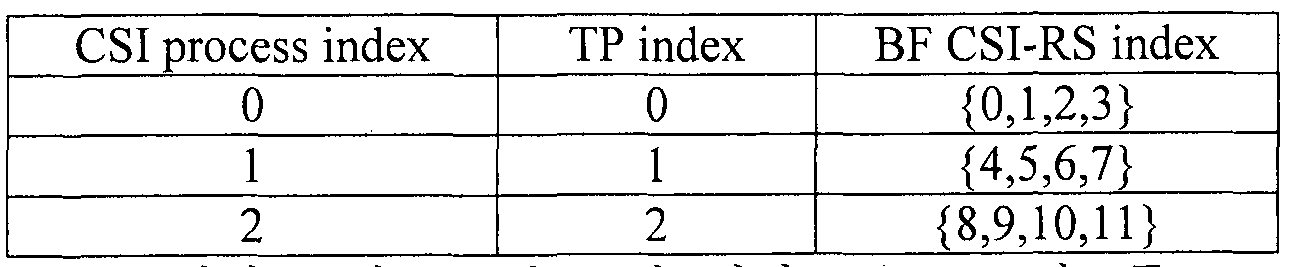
[149] 표 3 에서는 각 TP 별로 한 개의 CSI 프로세스를 UE 에게 설정하지만, 이는 일례일 뿐이며, 각 TP 별로 두 개 이상의 CSI 프로세스를 설정할수 있다.
[150] 현재 정의된 PQI 필드의 사이즈는 2 비트이므로, DM-RS 와 QCL 가정이 가능한 CSI-RS, 즉 QCLed CSI-RS 를 최대 4개까지 UE에게 알려줄 수 있다. 기존 C()MP 에서는 하나의 UE 관점에서 Cc)MP 에 참여하는 TP 의 개수가 3 개로 한정됨에 따라, 2 비트 사이즈인 필드로 QCL 정보를 알려주기 충분하였지만, 도 9과 같이 CoMP와 FI)-MIM0가 함께 적용되는 경우, 3개 이상의 CSI-RS가 UE에게 설정된다. 도 9에서는 총 12개의 BF CSI-RS 가 UE 에게 설정된 것을 알 수 있다. 따라서, 현재 2 비트 사이즈의 PQI 필드는 12개 BF CSI-RS 중 하나를 지시해주기에는 부족하다ᅳ
[151] 만약, 하나의 TP 에서 전송하는 BF CSI-RS 간에 QCL 되어 있다면, 하나의 TP가 전송하는 임의의 한 CSI-RS 만을 PQI 로 지시 해도 UE는 DM-RS 채널 추정을 할 수 있다. 예를 들어 , UE 가 TP1 으로부터 데이터를 수신하고, 그 데이터는 BF CSI-RS 0에 적용된 빔을 이용하여 전송되었다면, PQI 필드를 통해 CSI-RS 1을 지시하더라도, CSI-RS 0 과 1 모두 동일 TP 가 전송하는 자원이므로 QCL 정보를 이용하는 데 문제가 발생하지 않는다.
[152] 하지만 만약 하나의 TP에서 전송하는 BF CSI-RS 간에 QCL 되어 있지 않는다면 (서로 상이한 빔이 적용되어 광범위 ( large scale) 채널 속성이 다를 수 있으므로) 어떤 BF CSI-RS 의 빔을 이용해 데이터 전송이 되었는지에 따라 정확히 그 BF CSI-RS 를 QCL 정보로 지시해 주어야 한다. 결과적으로 12 개의 BF CSI-RS 를 지시하기에는 현재 2 비트 사이즈의 PQI 필드는 부족하다. PQI 필드 사이즈를 증가시켜 문제를 해결할 수 있겠으나, DCI 사이즈의 증가에 따른 제어 오버헤드
증가가 불가피하다. 제어 오버헤드 증가를 최소화하면서 이러한 문제를 해결하기 위해 새로운 QCL 정보 전달 방식을 제안한다.
[153] 본 발명의 실시예에서 , 기지국은 UE에게 PQI 필드를 이용하여 UE에게 설정된 각 CSI 프로세스 별로 대표 CSI-RS 를 하나씩 정의한다. 예를 들어, PQI 스테이트 0 에는 CSI 프로세스 0 의 대표 CSI-RS 인 CSI-RS 0 를, PQI 스테이트 1 에는 CSI 프로세스 1 의 대표 CSI-RS 인 CSI-RS 4 를, PQI 스테이트 2 에는 CSI 프로세스 2 의 대표 CSI-RS 인 CSI-RS 8를 RRC 시그널링을 통하여 설정한다.
[154] 또는, PQI 스테이트에 QCL CSI-RS 인덱스 대신 QCL CSI 프로세스 인덱스를 정의할 수 있다. 이 경우 QCL CSI-RS 는 CSI 프로세스 내에 있는 임의의 CSI-RS 가 QCL 정보 획득을 위해 이용될 수 있거나, 미리 약속된 CSI-RS 인덱스, 예를 들어 CSI 프로세스 내에 최소 ( lowest ) CSI-RS 인덱스가 QCL 정보 획득을 위해 이용될 수 있다.
[155] UE 는 PQI 필드를 통해 대표 CSI-RS 를 확인한 후, 대표 CSI-RS 가 속한 CSI 프로세스를 확인하고, 그 CSI 프로세스에서 가장 최근 피드백 한 CRI 를 확인한다. UE 는 해당 CRI 에 연결된 CSI— RS 를 통해 QCL 정보를 획득하여 DM-RS 채널 추정을 실시한다. 예를 들어, PQI 필드에 CSI-RS 0 가 지시되었다면, UE 는 PQI 를 수신하기 전에 CSI 프로세스 0의 가장 최근 피드백 한 CRI를 확인한다.
[156] 도 10은 본 발명의 실시에에 따라 PUSCH를 통한 비주기적 CSI 피드백과 이에 기반한 PDSCH 전송을 수행하는 예를 도시한다.
[157] 도 10 을 참조하면, SF (sub frame) 2 에서 하향링크 데이터 (PDSCH)와 DCI 가 전송되었으며, DCI 내 PQI 는 CSI-RS 0 을 지시한 것을 알 수 있다. 이 경우, CSI 프로세스 0의 CRI와 CSI가 SF 0에서 PUSCH를 통해 가장 최근 보고되었으므로, UE는 SF 0에서 보고한 CRI 를 기준으로 QCL CSI-RS를 결정한다. SF 0에서 보고한 CRI 가 CSI-RS 3 을 가리키고 있다면, UE 는 CSI-RS 3 의 QCL 정보를 이용하여 채널 추정을 수행한다.
[158] 만약 도 10에서 CRI와 CSI가 SF 1에서 보고되었다면, UE는 SF 1의 CRI를 기준으로 QCL CSI-RS 를 결정하게 되는데, 이 경우 다음과 같은 문제가 발생한다. 기지국은 SF1 에서 수신한 CRI 를 이용하여 바로 다음 서브프레임인 SF2 의 데이터 스케줄링을 할 수 없다ᅳ 이는, SF1에서 수신한 CRI를 이용해 스케줄링하기 위해서는, 스케줄링을 위한 계산에 걸리는 시간을 감안하여 최소 N 서브프레임만큼의 시간이 필요하기 때문이다. 이러한 문제를 해결하기 위해 UE 는 PQI 를 수신하기 N
서브프레임 전 시점을 기준으로 가장 최근 피드백 한 CRI 를 확인하는 것이 바람직하다.
[159] 도 10에서는 N=2로 설정함에 따라 SF 0을 기준으로, 즉 SF 0를 포함한 과거 시점 기준으로, 가장 최근 피드백 한 CRI 인 SF 0 에서 보고된 CRI 를 이용하여 QCL CSI-RS 를 결정한다. N 은 기지국이 UE 에게 RRC 시그널링과 같은 상위 계층 시그널링으로 알려주거나, 특정 값으로 사전에 고정되거나, UE 가 기지국에게 보고할 수 있다.
[160] 기지국이 SF 0에서 CRI/CSI 수신에 실패했을 경우 상기 동작은 문제를 일으킬 수 있다. 이 문제를 해결 하기 위해 다음과 같은 동작을 고려할 수 있다.
[161] ― 기지국은 CRI/CSI 수신에 실패했을 경우에 UE 에게 데이터 전송을 하지 않는다. 기지국은 다시 CRI/CSI 피드백 트리거링을 하여 CRI/CSI 수신에 성공하고 이후 UE에게 데이터 전송을 한다ᅳ
[162] - 또는 기지국은 CRI/CSI 수신에 실패했을 경우에 UE 가 사용해야 할 QCL CSI-RS를 알려준다. 예를 들어 DCI내에 1 비트 사이즈의 지시자 (예를 들어 , 플래그 비트)를 정의하여, 그 값이 1 인 경우 UE 는 PQI 로 지시된 대표 CSI-RS 를 이용하여 QCL 정보를 가져은다 . 반면에, 그 값이 0인 경우 UE는 PQI를 수신하기 N서브프레임 전 시점을 기준으로 가장 최근 피드백 한 CRI를 확인하여 QCL 정보를 가져온다.
[163] ― 또는 UE가 QCL CSI-RS를 BD (bl ind detect i on) 할 수 있다. 즉 , UE는 PQI를 수신하기 N서브프레임 전 시점을 기준으로 가장 최근 피드백 한 CRI 의 CSI-RS또는 PQI 가 지시하는 대표 CSI-RS 중 하나를 BD 하여 QCL 정보를 획득하는 것으로, 결국 UE가 선택하는 것으로 볼 수 있다.
[164] 도 11 은 본 발명의 실시에에 따라 PUCCH 를 통한 주기적 CSI 피드백과 이에 기반한 PDSCH 전송을 수행하는 예를 도시한다.
[165] 도 10 의 PUSCH 와 다르게 PUCCH 는 CRI 와 나머지 CSI 가 분리되어 전송되는 것을 알 수 있다. 따라서, 도 10 의 N 과는 다른 값으로 N 이 설정되는 것이 바람직하다ᅳ 만약 도 11 에서도 N=2 인 경우, SF3 시점에 하향링크 데이터가 전송되었다면 UE 는 SF 0 의 CRI 를 기준으로 QCL 정보를 찾게 되는데, 기지국은 그 CRI에 해당하는 CQI 및 PMI를 SF2 시점에 수신하기 때문에 그 CRI와 CSI를 이용하여 데이터 스케줄링을 수행할 수 없다는 문제가 있다.
[166] 이러한 문제를 해결하기 위해서 PUCCH CSI 피드백 기준으로 스케줄링 하는 경우 N은 (즉, 도 11의 N) CQI 주기, CQI 대비 CRI의 서브프레임 오프셋 (subframe of fset ) , 그리고 PUSCH CSI 피드백의 N 값 (즉, 도 10 의 N)의 함수로 결정할 수 있다.
[167] 위 제안에서는 CoMP 환경을 가정함에 따라 PQI 정보가 필요하였으나, 비 (non)-Cc)MP 환경인 경우 또는 TP 가 하나로 고정된 경우는 PQI 정보가 불필요하다. 따라서 이 경우에는 PQI 정보를 다른 용도로 전용하는 것이 가능하다. 이를 위해 기지국은 RRC 시그널링과 같은 상위 계층 시그널링을 통해 PQI 를 상기 제안 방식 또는 기존 방식으로 이용할지 아니면 다른 용도로 전용할지 여부를 지시할 수 있다. 예를 들어, 기지국이 QCL 타입 A 또는 단일 (s ingle) CSI 프로세스가 설정된 경우 PQI는 다른 용도로 전용하여 사용한다.
[168] 추가적으로, 새로운 QCL 타입을 정의하는 방법 역시 고려할 필요가 있다. 단, 이는 CSI 프로세스 내의 CSIᅳ RS자원들 간에 QCL이라는 가정이 전제될 수 있다.
[169] 구체적으로, 도 9 과 표 3 의 예시에서 하나의 TP 에서 전송하는, 즉 하나의 CSI 프로세스 내에 정의된 BF CSI-RS 간에 QCL 되어 있다면, UE 는 그 CSI 프로세스 내의 설정된 임의의 CSI-RS 와 DM-RS 간 QCL 되어 있다고 가정할 수 있다. 이 경우 기지국은 DCI 등을 통해 하나의 CSI 프로세스를 UE 에게 지시해주고, UE 는 그 CSI 프로세스내 설정된 임의의 CSI-RSᅳ와 DM-RS 간 QCL 을 가정할 수 있다. 또는 UE 는 기존처럼 DCI 를 통해 QCL CSI-RS 인덱스를 수신하고, 그 CSI— RS 가 존재하는 CSI 프로세스 내 임의의 CSI— RS 와 DM-RS 간 QCL 을 가정할 수 있다. 이러한 QCL 타입을 QCL 타입 C라고 정의한다.
[170] QCL 타입 C 에서 CSI 프로세스 내에 QCL 되어 있는 여러 개의 CSI-RS 가 존재하므로, UE가 QCL 정보를 계산하기 위한 참조 신호 밀도가 기존 QCL 타입 B보다 높다. 예를 들어, QCL 타입 B 에서는 QCL CSI-RS 가 하나 존재하며 최소 5ms 주기로 존재하지만, QCL 타입 C 에서는 하나의 CSI 프로세스에 CSI-RS 가 5 개 설정되어 QCL CSIᅳ RS가 5개 존재하며, 이 다섯 개의 CSI-RS가 5ms 주기이며 서로 다른 서브프레임 오프셋을 가질 수 있다.
[171] 이 경우 QCL 타입 C 를 설정 받은 UE 는 매 서브프레임에 존재하는 QCL CSI-RS를 이용하여 도플러 확산 (Doppler spread) 및 도플러 천이 (Doppler shi ft )를
정확하게 추정할 수 있으며 , 결과적으로 UE 는 CRS 로부터 QCL 정보를 획득할 필'요가 없고 CSI— RS 만으로 정확한 QCL 정보를 획득하여 DM-RS 채널 추정을 실시할 수 있다.
[172] 도 12 는 본 발명의 일 실시예에 적용될 수 있는 기지국 및 단말의 구성을 도시한 도면이다.
[173] 도 12 를 참조하면, 무선 통신 시스템은 기지국 (1210) 및 단말 (1220)을 포함한다. 기지국 ( 1210)은 프로세서 ( 1213), 메모리 ( 1214) 및 무선 주파수 (Radio Frequency, RF) 유닛 ( 1211 , 1214)을 포함한다. 프로세서 ( 1213)는 본 발명에서 제안한 절차 및 /또는 방법들을 구현하도록 구성될 수 있다. 메모리 ( 1214)는 프로세서 ( 1213)와 연결되고 프로세서 ( 1213)의 동작과 관련한 다양한 정보를 저장한다. RF 유닛 ( 1216)은 프로세서 ( 1213)와 연결되고 무선 신호를 송신 및 /또는 수신한다.
[ 174] 단말 (1220)은 프로세서 ( 1223), 메모리 (1224) 및 RF 유닛 ( 1221, 1222)을 포함한다. 프로세서 ( 1223)는 본 발명에서 제안한 절차 및 /또는 방법들을 구현하도록 구성될 수 있다. 메모리 (1224)는 프로세서 ( 1223)와 연결되고 프로세서 ( 1223)의 동작과 관련한 다양한 정보를 저장한다. RF 유닛 ( 1221 , .1222)은 프로세서 ( 1223)와 연결되고 무선 신호를 송신 및 /또는 수신한다. 기지국 ( 1210) 및 /또는 단말 ( 1220)은 단일 안테나 또는 다중 안테나를 가질 수 있다.
[ 175] 이상에서 설명된 실시예들은 본 발명의 구성요소들과 특징들이 소정 형태로 결합된 것들이다. 각 구성요소 또는 특징은 별도의 명시적 언급이 없는 한 선택적인 것으로 고려되어야 한다ᅳ 각 구성요소 또는 특징은 다른 구성요소나 특징과 결합되지 않은 형태로 실시될 수 있다. 또한, 일부 구성요소들 및 /또는 특징들을 결합하여 본 발명의 실시예를 구성하는 것도 가능하다. 본 발명의 실시예들에서 설명되는 동작들의 순서는 변경될 수 있다. 어느 실시예의 일부 구성이나 특징은 다른 실시예에 포함될 수 있고, 또는 다른 실시예의 대웅하는 구성 또는 특징과 교체될 수 있다. 특허청구범위에서 명시적인 인용 관계가 있지 않은 청구항들을 결합하여 실시예를 구성하거나 출원 후의 보정에 의해 새로운 청구항으로 포함시킬 수 있음은 자명하다.
[176] 본 문서에서 기지국에 의해 수행된다고 설명된 특정 동작은 경우에 따라서는 그 상위 노드 (upper node)에 의해 수행될 수 있다. 즉, 기지국을 포함하는 복수의 네트워크 노드들 (network nodes)로 이루어지는 네트워크에서 단말과의 통신을 위해 수행되는 다양한 동작들은 기지국 또는 기지국 이외의 다른 네트워크 노드들에 의해
수행될 수 있음은 자명하다. 기지국은 고정국 ( f ixed stat ion) , Node B , eNodeB(eNB) , 억세스 포인트 (access point ) 등의 용어에 의해 대체될 수 있다.
[177] 본 발명에 따른 실시예는 다양한 수단, 예를 들어, 하드웨어, 펌웨어 ( f i r画 are) , 소프트웨어 또는 그것.들의 결합 등에 의해 구현될 수 있다. 하드웨어에 의한 구현의 경우ᅳ 본 발명의 일 실시예는 하나 또는 그 이상의 ASICs(appl icat ion speci f i c integrated ci rcui ts) , DSPs(digi tal 신호 CSI 프로세스 ors) , DSPDs(digi tal 신호 CSI 프로세스 ing devi ces) , PLDs(programmable logi c devices) , FPGAs ( f i eld programmable gate arrays) , 프로세서 , 콘트를러, 마이크로 콘트를러, 마이크로 프로세서 등에 의해 구현될 수 있다.
[178] 펌웨어나 소프트웨어에 의한 구현의 경우, 본 발명의 일 실시예는 이상에서 설명된 기능 또는 동작들올 수행하는 모들, 절차, 함수 등의 형태로 구현될 수 있다. 소프트웨어 코드는 메모리 유닛에 저장되어 프로세서에 의해 구동될 수 있다.
[179] 상기 메모리 유닛은 상기 프로세서 내부 또는 외부에 위치하여, 이미 공지된 다양한 수단에 의해 상기 프로세서와 데이터를 주고 받을 수 있다.
[18이 상술한 바와 같이 개시된 본 발명의 바람직한 실시예들에 대한 상세한 설명은 당업자가 본 발명을 구현하고 실시할 수 있도록 제공되었다. 상기에서는 본 발명의 바람직한 실시예들을 참조하여 설명하였지만, 해당 기술 분야의 숙련된 당업자는 본 발명의 영역으로부터 벗어나지 않는 범위 내에서 본 발명을 다양하게 수정 및 변경시킬 수 있음올 이해할 수 있을 것이다. 예를 들어, 당업자는 상술한 실시예들에 기재된 각 구성올 서로 조합하는 방식으로 이용할 수 있다. 따라서 , 본 발명은 여기에 나타난 실시형태들에 제한되려는 것이 아니라, 여기서 개시된 원리들 및 신규한 특징들과 일치하는 최광의 범위를 부여하려는 것이다.
[181] 본 발명은 본 발명의 정신 및 필수적 특징을 벗어나지 않는 범위에서 다른 특정한 형태로 구체화될 수 있다. 따라서, 상기의. 상세한 설명은 모든 면에서 제한적으로 해석되어서는 아니 되고 예시적인 것으로 고려되어야 한다. 본 발명의 범위는 첨부된 청구항의 합리적 해석에 의해 결정되어야 하고, 본 발명의 등가적 범위 내에서의 모든 변경은 본 발명의 범위에 포함된다. 본 발명은 여기에 나타난 실시형태들에 제한되려는 것이 아니라, 여기서 개시된 원리들 및 신규한 특징들과 일치하는 최광의 범위를 부여하려는 것이다. 또한, 특허청구범위에서 명시적인 인용
관계가 있지 않은 청구항들을 결합하여 실시예를 구성하거나 출원 후의 보정에 의해 새로운 청구항으로 포함할 수 있다.
【산업상 이용가능성】
[182] 본 발명은 단말, 릴레이, 기지국 등과 같은 무선 통신 장치에 사용될 수 있다.
Claims
【청구항 1】
무선 접속 시스템에서 단말이 하향링크 신호를 수신하는 방법에 있어서, 둘 이상의 CSI-RS (Channel Status Informat i on— Reference Signal ) 들로 구성되는 복수의 CSI (Channel Status Informat ion) 프로세스들에 관한 정보를 수신하는 단계 ;
특정 CSI-RS를 지시하는 지시자를 포함하는 하항링크 제어 신호를 수신하는 단계;
상기 복수의 CSI 프로세스들 중 상기 특정 CSI-RS가 대표 CSI-RS로 설정된 QCL (Quas i Co-Located) CSI 프로세스를 선택하는 단계;
상기 QCL CSI 프로세스에 포함된 상기 둘 이상의 CSI-RS들 중 가장 최근에 보고한 CSI— RS 지시자에 대웅하는 CSIᅳ RS를 DM— RS (Demodul at ion-Reference Signal )의 QCL CSI-RS로 선택하는 단계; 및
상기 DM-RS 및 상기 QCL CSI-RS를 이용하여, 하향링크 데이터 신호를 수신하는 단계를 포함하는 것을 특징으로 하는,
하향링크 신호 수신 방법 .
【청구항 2】
제 1 항에 있어서,
상기 대표 CSI-RS는,
해당 CSI 프로세스에 포함된 둘 이상의 CSI-RS들 중 최소 인텍스를 갖는 것을 특징으로 하는,
하향링크 신호 수신 방법 .
【청구항 3】
제 1 항에 있어서,
상기 DM-RS와 상기 QCL CSI-RS는,
도플러 확산 (Doppler spread) , 도플러 시프트 (Doppler shi ft ) , 평균 지연 (average delay) 및 지연 확산 (delay spread)이 동일한 것올 특징으로 하는,
하향링크 신호 수신 방법 .
【청구항 4】
제 1 항에 있어서,
상기 복수의 CSI 프로세스들은 서로 다른 TP (Transmi ssion Point )에 대웅하는 것을 특징으로 하는,
하향링크 신호 수신 방법 .
【청구항 5】
제 1 항에 있어서,
상기 CSI-RS 지시자를 보고한 서브프레임의 인텍스는 상기 하항링크 제어 신호를 수신한 서브프레임의 인덱스보다 기 설정된 값만큼 선행하는 것을 특징으로 하는,
하향링크 신호 수신 방법 .
【청구항 6】
제 1 항에 있어서,
상기 하항링크 제어 신호는 1 비트 사이즈의 플래그를 포함하고,
상기 폴레그가 제 1 값인 경우, 상기 QCL CSI 프로세스에 포함된 상기 둘 이상의 CSI-RS들 중 가장 최근에 보고한 CSI-RS 지시자에 대웅하는 CSI— RS를 상기 DM-RS 의 QCL CSIᅳ RS로 선택하고 ,
상기 플레그가 제 2 값인 경우, 상기 특정 CSI-RS를 상기 DM-RS 의 QCL CSI-RS로 선택하는 것을 특징으로 하는,
하향링크 신호 수신 방법 .
【청구항 71
무선 접속 시스템에서의 단말로서,
무선 통신 모들; 및
둘 이상의 CSI-RS (Channel Status Informat ion-Reference Signal ) 들로 구성되는 복수의 CSI (Channel Status Informat ion) 프로세스들에 관한 정보를 수신하고, 특정 CSI-RS를 지시하는 지시자를 포함하는 하항링크 제어 신호를 수신하며, 상기 복수의 CSI 프로세스들 중 상기 특정 CSI-RS가 대표 CSI-RS로 설정된 QCL (Quasi Co-Located) CSI 프로세스를 선택하고, 상기 QCL CSI 프로세스에 포함된 상기 둘 이상의 CSI-RS들 중 가장 최근에 보고한 CSI— RS 지시자에 대웅하는 CSI— RS를 DM-RS (Demodul at ion-Reference Signal )의 QCL CSI-RS로 선택하며, 상기 DM-RS 및 상기 QCL CSI-RS를 이용하여 하향링크 데이터 신호를 수신하는 프로세서를 포함하는 것을 특징으로 하는,
단말.
【청구항 8】
제 7 항에 있어서,
상기 대표 CSI-RS는,
해당 CSI 프로세스에 포함된 둘 이상의 CSI-RS들 중 최소 인텍스를 갖는 것을 특징으로 하는,
단말.
【청구항 9]
제 7 항에 있어서,
상기 DM-RS와상기 QCL CSI— RS는,
도플러 확산 (Doppler spread) , 도플러 시프트 (Doppler shi ft ) , 평균 지연 (average delay) 및 지연 확산 (del ay spread)이 동일한 것을 특징으로 하는, 단말. .
【청구항 10]
제 7 항에 있어서,
상기 복수의 CSI 프로세스들은 서로 다른 TP (Transmi ssion Point )에 대응하는 것을 특징으로 하는,
단말.
【청구항 11】
제 7 항에 있어서,
상기 CSI-RS 지시자를 보고한 서브프레임의 인덱스는 상기 하항링크 제어 신호를 수신한 서브프레임의 인덱스보다 기 설정된 값만큼 선행하는 것을 특징으로 하는,
단말.
【청구항 12】
제 Ί 항에 있어서,
상기 하항링크 제어 신호는 1 비트 사이즈의 플래그를 포함하고,
상기 플레그가 제 1 값인 경우, 상기 QCL CSI 프로세스에 포함된 상기 둘 이상의 CSI-RS들 중 가장 최근에 보고한 CSI— RS 지시자에 대웅하는 CSI-RS를 상기 DM-RS 의 QCL CSIᅳ RS로 선택하고,
WO 2017/119741 PCT/KR2(應) 00149 상기 플레그가 제 2 값인 경우, 상기 특정 CSI-RS를 상기 DM-RS 의 QCL
CSI-RS로 선택하는 것을 특징으로 하는'
단말.
Priority Applications (2)
| Application Number | Priority Date | Filing Date | Title |
|---|---|---|---|
| US16/067,473 US10707937B2 (en) | 2016-01-08 | 2017-01-05 | Method by which terminal receives downlink signal from base station in wireless communication system, and device therefor |
| EP17736113.6A EP3402105B1 (en) | 2016-01-08 | 2017-01-05 | Method by which terminal receives downlink signal from base station in wireless communication system, and device therefor |
Applications Claiming Priority (2)
| Application Number | Priority Date | Filing Date | Title |
|---|---|---|---|
| US201662276233P | 2016-01-08 | 2016-01-08 | |
| US62/276,233 | 2016-01-08 |
Publications (1)
| Publication Number | Publication Date |
|---|---|
| WO2017119741A1 true WO2017119741A1 (ko) | 2017-07-13 |
Family
ID=59273791
Family Applications (1)
| Application Number | Title | Priority Date | Filing Date |
|---|---|---|---|
| PCT/KR2017/000149 WO2017119741A1 (ko) | 2016-01-08 | 2017-01-05 | 무선통신 시스템에서 단말이 기지국으로 부터 하향링크 신호를 수신하는 방법 및 이를 위한 장치 |
Country Status (3)
| Country | Link |
|---|---|
| US (1) | US10707937B2 (ko) |
| EP (1) | EP3402105B1 (ko) |
| WO (1) | WO2017119741A1 (ko) |
Cited By (5)
| Publication number | Priority date | Publication date | Assignee | Title |
|---|---|---|---|---|
| WO2020029880A1 (en) * | 2018-08-10 | 2020-02-13 | Qualcomm Incorporated | Quasi-colocation indication for demodulation reference signals |
| CN112385152A (zh) * | 2018-07-04 | 2021-02-19 | 株式会社Ntt都科摩 | 用户终端 |
| CN112690029A (zh) * | 2018-09-20 | 2021-04-20 | 上海诺基亚贝尔股份有限公司 | 用于电信系统中的随机接入过程的方法和装置 |
| TWI729451B (zh) * | 2018-08-09 | 2021-06-01 | 南韓商Lg電子股份有限公司 | 在無線通訊系統中傳送及接收通道狀態資訊的方法及裝置 |
| CN113728560A (zh) * | 2019-02-21 | 2021-11-30 | 株式会社Ntt都科摩 | 用户终端以及无线通信方法 |
Families Citing this family (6)
| Publication number | Priority date | Publication date | Assignee | Title |
|---|---|---|---|---|
| US10505597B2 (en) * | 2016-05-09 | 2019-12-10 | Qualcomm Incorporated | Reference signals and link adaptation for massive MIMO |
| CN109474993B (zh) * | 2017-09-08 | 2022-10-28 | 北京紫光展锐通信技术有限公司 | 下行波束指示方法、装置及基站 |
| US10841955B2 (en) * | 2017-09-12 | 2020-11-17 | Mediatek Inc. | Rach quasi-colocation association |
| WO2019069127A2 (en) | 2017-10-02 | 2019-04-11 | Lenovo (Singapore) Pte, Ltd. | UPLINK POWER CONTROL |
| CN110832784B (zh) * | 2018-01-19 | 2022-01-11 | Oppo广东移动通信有限公司 | 信道状态信息csi测量的方法、终端设备和网络设备 |
| US11950264B2 (en) * | 2019-08-02 | 2024-04-02 | Qualcomm Incorporated | Joint sounding and measurement for access link and sidelink |
Citations (3)
| Publication number | Priority date | Publication date | Assignee | Title |
|---|---|---|---|---|
| US20140119266A1 (en) * | 2012-11-01 | 2014-05-01 | Samsung Electronics, Co., Ltd. | Transmission scheme and quasi co-location assumption of antenna ports for pdsch of transmission mode 10 for lte advanced |
| WO2015023647A1 (en) * | 2013-08-14 | 2015-02-19 | Qualcomm Incorporated | Enabling coordinated multipoint (comp) operation |
| US20150289235A1 (en) * | 2012-10-04 | 2015-10-08 | Lg Electronics Inc. | Method and apparatus for transreceiving downlink signal by considering antenna port relationship in wireless communication system |
Family Cites Families (5)
| Publication number | Priority date | Publication date | Assignee | Title |
|---|---|---|---|---|
| EP2654333B1 (en) * | 2012-04-19 | 2018-01-31 | Samsung Electronics Co., Ltd | Method and apparatus for quasi co-location identification of reference symbol ports for coordinated multi-point communication systems |
| WO2014042475A1 (ko) * | 2012-09-16 | 2014-03-20 | 엘지전자 주식회사 | 무선 통신 시스템에서 안테나 포트 관계를 고려한 하향링크 신호 송수신 방법 및 장치 |
| JP6514203B2 (ja) * | 2013-07-29 | 2019-05-15 | エルジー エレクトロニクス インコーポレイティド | 無線通信システムにおいてNIB CoMP方法及び装置 |
| US20160105817A1 (en) * | 2014-10-10 | 2016-04-14 | Telefonaktiebolaget L M Ericsson (Publ) | Method for csi feedback |
| US10225054B2 (en) * | 2014-11-07 | 2019-03-05 | Electronics And Telecommunications Research Institute | Method and apparatus for transmitting reference signal, method and apparatus for measuring and reporting channel state information, and method for configuring the same |
-
2017
- 2017-01-05 EP EP17736113.6A patent/EP3402105B1/en active Active
- 2017-01-05 US US16/067,473 patent/US10707937B2/en active Active
- 2017-01-05 WO PCT/KR2017/000149 patent/WO2017119741A1/ko active Application Filing
Patent Citations (3)
| Publication number | Priority date | Publication date | Assignee | Title |
|---|---|---|---|---|
| US20150289235A1 (en) * | 2012-10-04 | 2015-10-08 | Lg Electronics Inc. | Method and apparatus for transreceiving downlink signal by considering antenna port relationship in wireless communication system |
| US20140119266A1 (en) * | 2012-11-01 | 2014-05-01 | Samsung Electronics, Co., Ltd. | Transmission scheme and quasi co-location assumption of antenna ports for pdsch of transmission mode 10 for lte advanced |
| WO2015023647A1 (en) * | 2013-08-14 | 2015-02-19 | Qualcomm Incorporated | Enabling coordinated multipoint (comp) operation |
Non-Patent Citations (3)
| Title |
|---|
| ALCATEL -LUCENT SHANGHAI BELL ET AL.: "Remaining Issues of QCL and MR", R1-156713, 3GPP TSG RAN WG 1 MEETING #83, 7 November 2015 (2015-11-07), Anaheim, US, XP051042099 * |
| SAMSUNG: "Discussion on QCL Assumptions for FD-MIMO", R1-156779, 3GPP TSG RAN WG1 MEETING #83, 6 November 2015 (2015-11-06), Anaheim, CA , USA, XP051022254 * |
| See also references of EP3402105A4 * |
Cited By (6)
| Publication number | Priority date | Publication date | Assignee | Title |
|---|---|---|---|---|
| CN112385152A (zh) * | 2018-07-04 | 2021-02-19 | 株式会社Ntt都科摩 | 用户终端 |
| TWI729451B (zh) * | 2018-08-09 | 2021-06-01 | 南韓商Lg電子股份有限公司 | 在無線通訊系統中傳送及接收通道狀態資訊的方法及裝置 |
| WO2020029880A1 (en) * | 2018-08-10 | 2020-02-13 | Qualcomm Incorporated | Quasi-colocation indication for demodulation reference signals |
| US11863479B2 (en) | 2018-08-10 | 2024-01-02 | Qualcomm Incorporated | Quasi-colocation indication for demodulation reference signals |
| CN112690029A (zh) * | 2018-09-20 | 2021-04-20 | 上海诺基亚贝尔股份有限公司 | 用于电信系统中的随机接入过程的方法和装置 |
| CN113728560A (zh) * | 2019-02-21 | 2021-11-30 | 株式会社Ntt都科摩 | 用户终端以及无线通信方法 |
Also Published As
| Publication number | Publication date |
|---|---|
| EP3402105A4 (en) | 2019-07-31 |
| EP3402105A1 (en) | 2018-11-14 |
| EP3402105B1 (en) | 2021-10-06 |
| US10707937B2 (en) | 2020-07-07 |
| US20190013854A1 (en) | 2019-01-10 |
Similar Documents
| Publication | Publication Date | Title |
|---|---|---|
| US10819412B2 (en) | Codebook-based signal transmission/reception method in multi-antenna wireless communication system, and device for same | |
| US10720972B2 (en) | Method for transmitting and receiving channel state information in wireless communication system and device therefor | |
| CN110945823B (zh) | 在无线通信系统中执行协调发送的方法及其设备 | |
| US11095342B2 (en) | Method for transmitting and receiving channel state information in wireless communication system, and apparatus therefor | |
| EP2996258B1 (en) | Method for reporting channel state information for three dimensional beamforming in wireless communication system and apparatus for same | |
| EP3402105B1 (en) | Method by which terminal receives downlink signal from base station in wireless communication system, and device therefor | |
| JP6923515B2 (ja) | 無線通信システムにおいてランク指示子のビットサイズ決定方式及びそのための装置 | |
| KR102014797B1 (ko) | 무선 접속 시스템에서 채널상태정보를 전송하는 방법 및 장치 | |
| US8964591B2 (en) | Method and device for transmitting/receiving channel state information in a wireless communication system | |
| US10651901B2 (en) | Method for transmitting and receiving channel state information in multi-antenna wireless communication system, and apparatus therefor | |
| WO2018084622A1 (ko) | 무선 통신 시스템에서 채널 상태 정보 송수신 방법 및 이를 위한 장치 | |
| US10171154B2 (en) | Method for reporting beam index for 3D MIMO transmission in wireless communication system, and device therefor | |
| US10505608B2 (en) | Method for feeding back CSI information in wireless communication system, and apparatus therefor | |
| US10263671B2 (en) | Method for reporting reference signal indicator to base station by terminal in wireless communication system and apparatus therefor | |
| WO2014035216A1 (ko) | 무선 통신 시스템에서 안테나 가상화 방법 및 장치 | |
| WO2018231008A1 (ko) | 무선 통신 시스템에서 코드북 기반 상향링크 전송 방법 및 이를 위한 장치 | |
| US10608724B2 (en) | Method for reporting CSI in wireless communication system and device for same | |
| WO2013032271A2 (ko) | 무선 통신 시스템에서 채널상태정보를 전송하는 방법 및 장치 | |
| US10476570B2 (en) | Method by which terminal reports channel status information to base station in wireless communication system, and apparatus therefor |
Legal Events
| Date | Code | Title | Description |
|---|---|---|---|
| 121 | Ep: the epo has been informed by wipo that ep was designated in this application |
Ref document number: 17736113 Country of ref document: EP Kind code of ref document: A1 |
|
| NENP | Non-entry into the national phase |
Ref country code: DE |
|
| WWE | Wipo information: entry into national phase |
Ref document number: 2017736113 Country of ref document: EP |
|
| ENP | Entry into the national phase |
Ref document number: 2017736113 Country of ref document: EP Effective date: 20180808 |