WO2017119037A1 - ビデオシステム、ビデオ処理方法、プログラム、カメラシステムおよびビデオコンバーター - Google Patents
ビデオシステム、ビデオ処理方法、プログラム、カメラシステムおよびビデオコンバーター Download PDFInfo
- Publication number
- WO2017119037A1 WO2017119037A1 PCT/JP2016/005210 JP2016005210W WO2017119037A1 WO 2017119037 A1 WO2017119037 A1 WO 2017119037A1 JP 2016005210 W JP2016005210 W JP 2016005210W WO 2017119037 A1 WO2017119037 A1 WO 2017119037A1
- Authority
- WO
- WIPO (PCT)
- Prior art keywords
- video
- video signal
- adjustment parameter
- signal
- image adjustment
- Prior art date
Links
Images
Classifications
-
- H—ELECTRICITY
- H04—ELECTRIC COMMUNICATION TECHNIQUE
- H04N—PICTORIAL COMMUNICATION, e.g. TELEVISION
- H04N23/00—Cameras or camera modules comprising electronic image sensors; Control thereof
- H04N23/60—Control of cameras or camera modules
- H04N23/62—Control of parameters via user interfaces
-
- H—ELECTRICITY
- H04—ELECTRIC COMMUNICATION TECHNIQUE
- H04N—PICTORIAL COMMUNICATION, e.g. TELEVISION
- H04N21/00—Selective content distribution, e.g. interactive television or video on demand [VOD]
- H04N21/20—Servers specifically adapted for the distribution of content, e.g. VOD servers; Operations thereof
- H04N21/23—Processing of content or additional data; Elementary server operations; Server middleware
- H04N21/234—Processing of video elementary streams, e.g. splicing of video streams or manipulating encoded video stream scene graphs
-
- H—ELECTRICITY
- H04—ELECTRIC COMMUNICATION TECHNIQUE
- H04N—PICTORIAL COMMUNICATION, e.g. TELEVISION
- H04N1/00—Scanning, transmission or reproduction of documents or the like, e.g. facsimile transmission; Details thereof
- H04N1/46—Colour picture communication systems
- H04N1/56—Processing of colour picture signals
- H04N1/60—Colour correction or control
- H04N1/603—Colour correction or control controlled by characteristics of the picture signal generator or the picture reproducer
-
- H—ELECTRICITY
- H04—ELECTRIC COMMUNICATION TECHNIQUE
- H04N—PICTORIAL COMMUNICATION, e.g. TELEVISION
- H04N1/00—Scanning, transmission or reproduction of documents or the like, e.g. facsimile transmission; Details thereof
- H04N1/46—Colour picture communication systems
- H04N1/56—Processing of colour picture signals
- H04N1/60—Colour correction or control
- H04N1/6058—Reduction of colour to a range of reproducible colours, e.g. to ink- reproducible colour gamut
-
- H—ELECTRICITY
- H04—ELECTRIC COMMUNICATION TECHNIQUE
- H04N—PICTORIAL COMMUNICATION, e.g. TELEVISION
- H04N21/00—Selective content distribution, e.g. interactive television or video on demand [VOD]
- H04N21/40—Client devices specifically adapted for the reception of or interaction with content, e.g. set-top-box [STB]; Operations thereof
- H04N21/43—Processing of content or additional data, e.g. demultiplexing additional data from a digital video stream; Elementary client operations, e.g. monitoring of home network or synchronising decoder's clock; Client middleware
- H04N21/44—Processing of video elementary streams, e.g. splicing a video clip retrieved from local storage with an incoming video stream or rendering scenes according to encoded video stream scene graphs
- H04N21/4402—Processing of video elementary streams, e.g. splicing a video clip retrieved from local storage with an incoming video stream or rendering scenes according to encoded video stream scene graphs involving reformatting operations of video signals for household redistribution, storage or real-time display
-
- H—ELECTRICITY
- H04—ELECTRIC COMMUNICATION TECHNIQUE
- H04N—PICTORIAL COMMUNICATION, e.g. TELEVISION
- H04N23/00—Cameras or camera modules comprising electronic image sensors; Control thereof
- H04N23/60—Control of cameras or camera modules
- H04N23/667—Camera operation mode switching, e.g. between still and video, sport and normal or high- and low-resolution modes
-
- H—ELECTRICITY
- H04—ELECTRIC COMMUNICATION TECHNIQUE
- H04N—PICTORIAL COMMUNICATION, e.g. TELEVISION
- H04N23/00—Cameras or camera modules comprising electronic image sensors; Control thereof
- H04N23/70—Circuitry for compensating brightness variation in the scene
- H04N23/741—Circuitry for compensating brightness variation in the scene by increasing the dynamic range of the image compared to the dynamic range of the electronic image sensors
-
- H—ELECTRICITY
- H04—ELECTRIC COMMUNICATION TECHNIQUE
- H04N—PICTORIAL COMMUNICATION, e.g. TELEVISION
- H04N23/00—Cameras or camera modules comprising electronic image sensors; Control thereof
- H04N23/95—Computational photography systems, e.g. light-field imaging systems
- H04N23/951—Computational photography systems, e.g. light-field imaging systems by using two or more images to influence resolution, frame rate or aspect ratio
-
- H—ELECTRICITY
- H04—ELECTRIC COMMUNICATION TECHNIQUE
- H04N—PICTORIAL COMMUNICATION, e.g. TELEVISION
- H04N5/00—Details of television systems
- H04N5/14—Picture signal circuitry for video frequency region
- H04N5/16—Circuitry for reinsertion of DC and slowly varying components of signal; Circuitry for preservation of black or white level
- H04N5/18—Circuitry for reinsertion of DC and slowly varying components of signal; Circuitry for preservation of black or white level by means of "clamp" circuit operated by switching circuit
- H04N5/185—Circuitry for reinsertion of DC and slowly varying components of signal; Circuitry for preservation of black or white level by means of "clamp" circuit operated by switching circuit for the black level
Definitions
- This technology relates to a video system, a video processing method, a program, a camera system, and a video converter that process a plurality of types of video signals whose levels and colors are adjusted under different conditions.
- HDR High Dynamic Range
- SDR Standard Dynamic Range
- Patent Document 1 discloses a method for encoding HDR video and LDR video together.
- This technique is intended to solve various problems in the case of processing a plurality of video signals adjusted under different conditions.
- a video system includes: A camera system and a video converter,
- the camera system includes: A first video signal is generated based on the first image adjustment parameter from the pixel signal generated by the imaging unit that images the subject and obtains a pixel signal, and a second image different from the first image adjustment parameter A second video signal is generated based on the adjustment parameter, and transmission information obtained by adding the first adjustment parameter and the second adjustment parameter to the second video signal is transmitted via the first transmission path.
- the video converter Receiving the transmission information via the first transmission path; Based on the second image adjustment parameter included in the transmission information, the second video signal included in the transmission information is inversely transformed to generate a restored pixel signal, and the second video signal included in the transmission information
- the first image adjustment parameter and the second image adjustment parameter include image adjustment parameters related to levels of the first video signal and the second video signal,
- the dynamic range of the first video signal is narrower than the dynamic range of the second video signal.
- the first image adjustment parameter and the second image adjustment parameter include image adjustment parameters related to colors of the first video signal and the second video signal. It may be.
- the first video signal may be SDR (Standard Dynamic Range) video
- the second video signal may be HDR (High Dynamic Range) video.
- only the second video signal of the first video signal and the second video signal is transmitted through the second transmission path from the camera system to the video converter.
- the first processing circuit and the second processing circuit are configured as described above,
- the second processing circuit is configured to transmit an output video signal corresponding to the first video signal to a display via a third transmission path different from the second transmission path. Good.
- a first processing circuit generates a first video signal based on a first image adjustment parameter from the pixel signal generated by an imaging unit that images a subject and obtains a pixel signal, and the first image adjustment parameter
- a second video signal is generated based on a second image adjustment parameter different from the first image, and transmission information obtained by adding the first adjustment parameter and the second adjustment parameter to the second video signal is transmitted as a first transmission signal.
- a second processing circuit configured to generate a restored pixel signal by inversely converting the second video signal included in the transmission information based on a second image adjustment parameter included in the transmission information; Based on the first adjustment parameter included in the information, an adjustment process corresponding to the first video signal is performed on the restored signal to generate an output video signal corresponding to the first video signal.
- a first video signal is generated based on the first image adjustment parameter from the pixel signal generated by the imaging unit that images the subject and obtains a pixel signal, and a second image different from the first image adjustment parameter
- a second video signal is generated based on the adjustment parameter, and transmission information obtained by adding the first adjustment parameter and the second adjustment parameter to the second video signal is transmitted via the first transmission path.
- the video converter Receiving the transmission information via the first transmission path; Based on the second image adjustment parameter included in the transmission information, the second video signal included in the transmission information is inversely transformed to generate a restored pixel signal, and the second video signal included in the transmission information
- a computer as a second processing circuit that performs an adjustment process corresponding to the first video signal on the restoration signal based on the adjustment parameter of 1 and generates an output video signal corresponding to the first video signal. The program to be run.
- a first video signal is generated based on the first image adjustment parameter from the pixel signal generated by the imaging unit that images the subject and obtains a pixel signal, and a second image different from the first image adjustment parameter
- a second video signal is generated based on the adjustment parameter, and transmission information obtained by adding the first adjustment parameter and the second adjustment parameter to the second video signal is transmitted via the first transmission path. 1 processing circuit.
- a first video signal is generated based on the first image adjustment parameter from the pixel signal generated by the imaging unit that images the subject and obtains a pixel signal, and a second image different from the first image adjustment parameter
- a camera that generates a second video signal based on an adjustment parameter and transmits transmission information obtained by adding the first adjustment parameter and the second adjustment parameter to the second video signal via a first transmission path.
- the second video signal included in the transmission information is inversely transformed to generate a restored pixel signal, and the transmission information
- An adjustment process corresponding to the first video signal is performed on the restored signal based on the included first adjustment parameter, and an output corresponding to the first video signal is performed. It comprises a second processing circuit for generating a video signal.
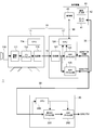
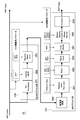
- FIG. 1 is a block diagram showing an overall configuration of a video system 1 according to the first embodiment of the present technology.
- the video system 1 includes a camera system 10 and a video converter 20.
- the camera system 10 and the video converter 20 are connected through a main line transmission line 30.
- the camera system 10 includes an imaging device 11 and a camera control unit 12.
- the imaging device 11 and the camera control unit 12 are connected through a camera cable 13 such as an optical fiber.
- the imaging apparatus 11 includes an optical system 110 having a lens group for imaging, an imaging element 111, a preprocessor 112, a transmission unit 113, and a CPU 114.
- the image sensor 111 is an image sensor such as a CMOS (Complementary Metal-Oxide-Semiconductor) element or a CCD (Charge-Coupled Device), and converts the light captured through an optical system (not shown) into an electrical pixel signal corresponding to the light intensity. Convert.
- CMOS Complementary Metal-Oxide-Semiconductor
- CCD Charge-Coupled Device
- the “imaging unit” corresponds to the imaging device 11 described above.
- the preprocessor 112 performs signal correction processing such as defect correction and lens aberration correction on the pixel signal obtained by the image sensor 111.
- the transmission unit 113 performs a process of transmitting the pixel signal output from the preprocessor 112 to the camera control unit 12 through the camera cable 13. That is, the pixel signal transmitted to the camera control unit 12 by the transmission unit 113 is a RAW image signal that has not been subjected to processing relating to gain or dynamic range, debayer processing, gamma signal processing, or the like.
- the CPU 114 is a controller that controls each part of the imaging device 11 and communicates with the CPU 124 of the camera control unit 12 through the camera cable 13.
- the camera control unit 12 includes a transmission unit 121, an HDR process unit 122, an SDR process unit 123, and a CPU 124.
- the transmission unit 121 includes a communication circuit that performs wired or wireless communication.
- the transmission unit 121 receives the pixel signal transmitted from the imaging device 11 through the camera cable 13 (first transmission path), and performs HDR processing unit 122 and SDR processing unit. 123.
- the HDR process unit 122 performs a process of generating an HDR video while applying various adjustments to the pixel signal supplied from the transmission unit 121 based on parameter information for HDR adjustment.
- the HDR video generated by the HDR process unit 122 is transmitted to the video converter 20 through the main transmission path 30 with the parameter information for HDR adjustment and the parameter information for SDR adjustment added.
- the CPU 124 may perform a process of multiplexing the parameter information for adjustment in the HDR video stream, and HDR as a metadata file associated with the HDR video stream. It may be output to the main transmission line 30 separately from the video.
- the main transmission line 30 may be configured as a single transmission line, or an HDR video stream is transmitted through a dedicated transmission line having a transmission band larger than that of the general-purpose transmission line, and adjustment parameter information is transmitted to the dedicated transmission line. It may be configured as a plurality of transmission paths such as sending by a general-purpose transmission path having a smaller transmission band.
- the SDR process unit 123 performs processing for generating SDR video while applying various adjustments to the pixel signal supplied from the transmission unit 121 based on parameter information of SDR adjustment.
- the SDR video generated by the SDR process unit 123 is transmitted through the output transmission path 35 to the display 41 of the operation device 40 of the video producer, for example.
- the output transmission paths of the HDR process section 121 and the SDR process section 123 can be different transmission paths.
- the SDR video is displayed on the display 41 of the operation device 40 of the video producer via the output transmission line 35 (third transmission line) independent of the main transmission line 30 (second transmission line).
- the HDR process unit 122, the SDR process unit 123, and the CPU 124 are configured by one or a plurality of integrated circuits, and correspond to the first processing circuit in the configuration of the present technology.
- the CPU 124 is a controller that controls each unit in the camera control unit 12.
- the CPU 124 can communicate with the HDR process unit 122 and the SDR process unit 123 to control adjustment contents to be added to the image signal in each process.
- the CPU 124 adds the parameter information used for adjusting the pixel signal in the HDR process by the HDR process unit 122 and the SDR process by the SDR process unit 123 to the HDR video generated by the HDR process unit 122. Then, control is performed so that the video signal is transmitted to the video converter 20 through the main transmission line 30.
- the CPU 124 can communicate with the operation device 40 connected via a communication path 50 such as a LAN (Local Area Network).
- the operation device 40 includes a display 41, an operation input unit 42, and a control unit 43.
- the operation device 40 may be configured by an information processing device such as a personal computer, or may be configured by a dedicated control panel or the like made for camera control.
- the operation input unit 42 may be configured with, for example, operation keys, a mouse, a trackball, a dial, a lever, a touch sensor panel, a remote controller, and the like.
- the control unit 43 of the operation device 40 is configured by a circuit such as a CPU, receives various control commands and setting information from a producer such as VE (Video Engineer), and communicates with the CPU 124 of the camera control unit 12 via the communication path 50. Communicate between.
- a circuit such as a CPU
- receives various control commands and setting information from a producer such as VE (Video Engineer)
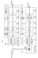
- FIG. 2 is a block diagram showing a functional configuration of the HDR process unit 122 and the SDR process unit 123 of the camera control unit 12.
- the HDR process unit 122 includes an HDR gain adjustment unit 221, a matrix processing unit 223, a black level correction unit 225, a detail processing unit 227, an OETF unit 228, and a formatter 229.
- the HDR gain adjustment unit 221 performs RGB gain control for white balance adjustment in addition to master gain control.
- the matrix processing unit 223 is a pixel signal that has passed through the HDR gain adjustment unit 221 based on color gamut information (HDR-Color Gamut) that is a part of the parameter information for HDR adjustment and is information about the color of the HDR video.
- Color image data is obtained by performing debayer processing, linear matrix processing, and the like.
- the black level correction unit 225 corrects the black level of the color image data based on the information (HDR-Black) for black level correction that is part of the parameter information for HDR adjustment.
- the detail processing unit 227 performs detail processing of color image data.
- the OETF unit 228 performs OETF (Optical-Electro Transfer Function) on color image data based on OETF information that is information on HDR transmission gamma, which is a part of parameter information for HDR adjustment. Gamma signal processing.
- the formatter 229 converts the color image data that has passed through the OETF unit 228 into an HDR video transmission format.
- the SDR process unit 123 includes a resolution conversion unit 230, an SDR gain adjustment unit 231, a matrix processing unit 233, a black level correction unit 235, a knee detail processing unit 237, a gamma processing unit 238, and a formatter 239.
- the resolution conversion unit 230 converts the resolution (for example, 4K resolution) of the pixel signal transmitted from the imaging device 11 into HD resolution.
- the SDR gain adjustment unit 231 performs master gain control based on a relative gain (Relative-Gain) that is a part of parameter information for SDR adjustment and is parameter information regarding the level of SDR video and HDR video.
- the RGB gain for white balance adjustment is controlled.
- the relative gain is a parameter indicating a ratio between a gain for the pixel signal in the HDR process and a gain for the pixel signal in the SDR process so that the contrast ratio between the HDR video and the SDR video can be adjusted.
- the relative range defines how many times the dynamic range of the HDR video is set with respect to the dynamic range of the SDR video.
- the ratio of the master gain on the SDR process side to the master gain on the HDR process side can be set to an arbitrary ratio such as 1, 1/2, for example. In this way, if the ratio between the master gain on the HDR process side and the master gain on the SDR process side is set, the dynamic range of the HDR video having a correlation with the dynamic range of the SDR video can be obtained.
- the upper limit of the dynamic range of SDR video is given by the standard white (Diffuse-White) selected by the producer.
- the reference white (Diffuse-White) of the SDR video by selecting the reference white (Diffuse-White) of the SDR video, based on the correlation based on the relative range, the upper limit reference of the dynamic range of the HDR video (the HDR video The reference white (Diffuse-White) is also determined.
- the relative range should be appropriately selected according to the shooting environment such as daytime, nighttime, indoors, outdoors, in the studio, in fine weather, and in rainy weather. Therefore, a plurality of types of relative ranges associated with various shooting environments are prepared.
- a method of preparing a plurality of types of relative ranges associated with the shooting environment a method of comparing the apparent brightness of the SDR video and the HDR video simultaneously output from the camera control unit 12 with human eyes is conceivable. .
- Each time the value of the relative range is changed, the SDR video and the HDR video are compared, and the relative range in which the apparent brightness of the SDR video and the HDR video is close may be determined as the optimum reactive range for the shooting environment.
- the relative gain may be information for performing white balance processing or contrast processing for SDR video.
- the relative gain is a value other than the numerical value of the ratio to the gain of the HDR signal, such as a gain value for RAW data that is a sensor output value. Information may be used.
- the luminance dynamic range of HDR video is wider than that of SDR video.
- the luminance dynamic range of the SDR video is 0 to 100%
- the luminance dynamic range of the HDR video is, for example, 100% to 1300% or 100% to 10000%.
- the luminance range of the output of the imaging device 10 is 0 to 600%.
- the matrix processing unit 233 is a pixel signal that has passed through the SDR gain adjustment unit 231 based on color gamut information (SDR-Color Gamut) that is a part of parameter information for SDR adjustment and is information about the color of the SDR video.
- Color image data is obtained by performing debayer processing, linear matrix processing, and the like.
- the black level correction unit 235 corrects the black level of the color image data based on the information for black level correction (SDR-Black) which is a part of the parameter information for SDR adjustment.
- SDR-Black black level correction
- the knee detail processing unit 237 performs knee correction on color image data based on information (KNEE) regarding knee correction, which is part of parameter information for SDR adjustment, and also performs detail processing.
- KNEE information regarding knee correction
- the gamma processing unit 238 generates a gamma for the dynamic range set in the SDR gain adjustment unit 231 based on information (SDR-D-Range-Gamma) related to compression of the dynamic range, which is a part of parameter information for SDR adjustment. It performs signal processing and simultaneously performs gamma signal processing for display.
- information SDR-D-Range-Gamma
- the formatter 239 converts the color image data into an SDR video transmission format.
- a producer such as a VE (Video Engineer) that operates an operating device connected to the camera control unit 12 via a communication path such as a LAN (Local Area Network).
- VE Video Engineer
- LAN Local Area Network
- the video converter 20 includes an inverse HDR process unit 201, an SDR process unit 202, and a CPU 203.
- the CPU 203 extracts the parameter information for HDR adjustment and the parameter information for SDR adjustment from the HDR video with parameter information received through the main transmission line 30, and provides the parameter information for HDR adjustment to the inverse HDR process unit 201. In addition, the CPU 203 provides parameter information for SDR adjustment to the SDR process unit 202.
- the reverse HDR process unit 201 performs a reverse HDR process on the HDR video received through the main transmission line 30 by using parameter information for HDR adjustment. That is, the inverse HDR processing unit 201 removes the adjustment component from the HDR video and generates a restored pixel signal.
- the SDR processing unit 202 generates an output video signal corresponding to the SDR video generated in the camera control unit 12 from the restored pixel signal obtained by the inverse HDR processing unit 201 using the parameter information for SDR adjustment. To do.
- the reverse HDR process unit 201, the SDR process unit 202, and the CPU 203 are configured by one or a plurality of integrated circuits, and correspond to the second processing circuit in the configuration of the present technology.
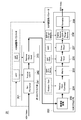
- FIG. 3 is a block diagram showing a functional configuration of the inverse HDR process unit 201 and the SDR process unit 202 in the video converter 20.
- the inverse HDR process unit 201 includes a deformer 241, an inverse OETF unit 242, and a black level correction removal unit 243.
- Deformatter 241 cancels the HDR video transmission format.
- the inverse OETF unit 242 removes the OETF gamma applied to the HDR video based on the information (OETF type) regarding the HDR transmission gamma that is a part of the parameter information for HDR adjustment.
- the black level correction removing unit 243 cancels the black level correction applied to the HDR video based on the information (HDR-Black) for black level correction that is a part of the parameter information for HDR adjustment. I do.
- the configuration of the SDR process unit 202 of the video converter 20 is the same as the configuration of the SDR process unit 202 of the camera control unit 12. That is, the SDR processing unit 202 of the video converter 20 includes a resolution conversion unit 230, an SDR gain adjustment unit 231, a matrix processing unit 233, a black level correction unit 235, a knee detail processing unit 237, a gamma processing unit 238, and a formatter 239. .
- the HDR video is transmitted to the video converter 20 through the main transmission line 30 because the SDR video confirms the video producer's appearance. This is because only the HDR video is transmitted to the main transmission line 30. Further, if HDR video and SDR video are simultaneously transmitted through the main transmission line 30, the transmission band of the main transmission line 30 may be compressed. For these reasons, it is desirable that only HDR video is transmitted to the main transmission line 30. Therefore, in the camera system 10, for example, the output transmission path 35 of the SDR process unit 123 outputs SDR video, and the SDR video for visual confirmation of the captured video is displayed on the display 41 of the operating device 40. 30 can be configured not to output SDR video.
- both videos can be handled as main video by handling with HDR video and converting to SDR at the final stage.
- the HDR video is transmitted to the video converter 20 through the main transmission line 30, and the video converter 20 converts the HDR video from the HDR video to the camera system 10.
- the operation in the case of generating an output video signal corresponding to the SDR video generated in (1) will be described.
- the pixel signal obtained by the imaging device 11 is transmitted to the camera control unit 12 through the camera cable 13 by the transmission unit 113.
- the pixel signal received by the transmission unit 121 is supplied to the HDR processing unit 122 and the SDR processing unit 123.
- various adjustments are made based on the HDR adjustment parameter information given by the CPU 124 while the HDR video is generated from the pixel signal.
- various adjustments are made based on the parameter information for SDR adjustment given by the CPU 124 while the SDR video is generated from the pixel signal.
- the CPU 124 adds the HDR adjustment parameter information used for the HDR video adjustment by the HDR process unit 122 and the SDR adjustment parameter information used for the SDR video adjustment by the SDR process unit 123 to the HDR video and transmits the main line. Control is performed so as to be transmitted to the video converter 20 through the path 30.
- the SDR video generated by the SDR process unit 123 is transmitted and displayed on the display 41 of the operation device 40 of the video producer, for example.
- the CPU 203 extracts the parameter information for HDR adjustment and the parameter information for SDR adjustment from the received HDR video with parameter information.
- the CPU 203 provides the extracted HDR adjustment parameter information to the inverse HDR process unit 201 and also provides the SDR process unit 202 with parameter information for SDR adjustment.
- the HDR video is inversely transformed using the parameter information for HDR adjustment given from the CPU 203, and a restored pixel signal obtained by restoring the original pixel signal is generated.
- the restored pixel signal is supplied to the SDR process unit 202.
- the SDR process unit 202 generates an output video signal corresponding to the SDR video generated in the camera control unit 12 from the restored pixel signal obtained by the inverse HDR process unit 201 using the parameter information for SDR adjustment. Is done.
- the output video signal corresponding to the generated SDR video is transmitted to and displayed on a display different from the display 41 of the controller device 40 to which the SDR video generated by the camera control unit 12 is transmitted, for example.
- the camera control unit 12 adds the parameter information for HDR adjustment and the parameter information for SDR adjustment to the generated HDR video and transmits the video converter through the main transmission line 30. 20 is transmitted.
- the video converter 20 restores the original pixel signal based on the parameter information for HDR adjustment added to the HDR video, and also uses the parameter information for SDR adjustment added to the HDR video for the restored pixel signal.
- the output video signal corresponding to the SDR video generated in the camera control unit 12 is reproduced.
- an output video signal whose representation is as close as possible to the SDR video generated simultaneously with the HDR video from the pixel signal in the camera control unit 12 can be obtained by conversion from the HDR video in the video converter 20.
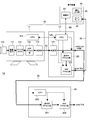
- FIG. 4 is a block diagram illustrating a configuration of a video system 1A according to the second embodiment of the present technology.
- the video system 1 ⁇ / b> A includes an HDR process unit 115 in the imaging apparatus 11.
- the HDR processing unit 115 generates an HDR video while applying various adjustments to the pixel signal output from the preprocessor 112 based on parameter information for HDR adjustment, and supplies the HDR video to the transmission unit 113.
- the transmission unit 113 transmits the HDR video supplied from the HDR process unit 115 to the camera control unit 12 through the camera cable 13.
- the CPU 114 of the imaging apparatus 11 communicates with the CPU 124 of the camera control unit 12 through the camera cable 13, and the HDR control parameter information used for generating the HDR video in the HDR process unit 115 is transmitted to the camera control unit. 12 CPUs 124 are notified.
- the camera control unit 12 includes a transmission unit 121, an inverse HDR process unit 125, an SDR process unit 123, and a CPU 124.
- the CPU 124 communicates with the CPU 114 of the imaging device 11 through the camera cable 13, receives parameter information for HDR adjustment from the CPU 114 of the imaging device 11, and provides the parameter information to the inverse HDR processing unit 125.
- the transmission unit 121 of the camera control unit 12 supplies the HDR video transmitted from the imaging device 11 through the camera cable 13 to the reverse HDR processing unit 125 and sends it to the main transmission line 30.
- the inverse HDR process unit 125 generates a restored pixel signal obtained by removing the adjustment component from the HDR video using the parameter information for HDR adjustment given from the CPU 124, and supplies it to the SDR process unit 123.
- the SDR processing unit 123 performs processing for generating SDR video while applying various adjustments to the restored pixel signal based on parameter information of SDR adjustment.
- the SDR video generated by the SDR process unit 123 is transmitted and displayed on the display 41 of the operation device 40 of the video producer, for example.
- the CPU 124 adjusts the SDR video by the SDR process unit 123 and the parameter information for HDR adjustment used for generating the restored pixel signal from the HDR video in the reverse HDR process by the reverse HDR process unit 125.
- the parameter information for SDR adjustment used in the above is added to the HDR video, and is controlled to be transmitted to the video converter 20 through the main transmission line 30.
- the HDR process unit 115 and CPU 114 of the imaging apparatus 11 and the reverse HDR process unit 125, SDR process unit 123, and CPU 124 of the camera control unit 12 correspond to a first processing circuit in the configuration of the present technology.
- the video converter 20 includes an inverse HDR process unit 201, an SDR process unit 202, and a CPU 203. These are the same as the configuration of the video converter 20 of the first embodiment.
- FIG. 5 is a block diagram showing a functional configuration of the inverse HDR process unit 125 and the SDR process unit 123 of the camera control unit 12.
- the inverse HDR process unit 125 includes a deformer 251, an inverse OETF unit 252, and a black level correction removal unit 253.
- Deformer 251 cancels the HDR video transmission format.
- the inverse OETF unit 252 removes the OETF gamma applied to the HDR video based on the information (OETF type) regarding the HDR transmission gamma that is a part of the parameter information for HDR adjustment.
- the black level correction removal unit 253 cancels the black level correction applied to the HDR video based on the information (HDR-Black) for black level correction that is a part of the parameter information for HDR adjustment. I do.
- the SDR process unit 123 includes a resolution conversion unit 260, an SDR gain adjustment unit 261, a matrix processing unit 263, a black level correction unit 265, a knee detail processing unit 267, a gamma processing unit 268, and a formatter 269.
- the configuration of the SDR process unit 123 is the same as the configuration of the SDR process unit 202 of the camera control unit 12.
- the pixel signal output from the preprocessor 112 is supplied to the HDR process unit 115, and various adjustments are made based on the parameter information for HDR adjustment given from the CPU 114 in the HDR process unit 115.
- HDR video is generated.
- the generated HDR video is transmitted to the camera control unit 12 through the camera cable 13 by the transmission unit 113.
- the CPU 114 of the imaging device 11 communicates with the CPU 124 of the camera control unit 12 through the camera cable 13, and parameter information for HDR adjustment used for HDR video adjustment by the HDR process unit 115 is stored in the camera control unit 12.
- the CPU 124 is notified.
- the CPU 124 of the camera control unit 12 gives the HDR adjustment parameter information notified from the CPU 114 of the imaging device 11 to the inverse HDR processing unit 125.
- the HDR video received by the transmission unit 121 of the camera control unit 12 passes through the camera control unit 12 and is supplied to the main transmission line 30 and transmitted to the video converter 20 through the main transmission line 30.
- the HDR video received by the transmission unit 121 is also supplied to the reverse HDR processing unit 125.
- a restored pixel signal is generated by removing the adjustment component from the HDR video.
- the generated restored pixel signal is supplied to the SDR process unit 123.
- the SDR processing unit 123 performs processing for generating SDR video while applying various adjustments to the restored pixel signal based on the parameter information for SDR adjustment given from the CPU 124.
- the generated SDR video is transmitted and displayed on the display 41 of the operation device 40 of the video producer, for example.
- the CPU 124 receives the parameter information for HDR adjustment notified from the CPU 114 of the imaging device 11 and the parameter information for SDR adjustment used for adjusting the restored pixel signal in the SDR process unit 123, as a camera control unit. It is added to the HDR video that passes through the video signal 12 and is transmitted to the video converter 20 through the main transmission line 30.
- the operation of the video converter 20 is the same as in the first embodiment. That is, when the video converter 20 receives the HDR video with parameter information through the main transmission line 30, the CPU 203 extracts the parameter information for HDR adjustment and the parameter information for SDR adjustment from the received HDR video with parameter information. To do.
- the CPU 203 provides the extracted HDR adjustment parameter information to the inverse HDR process unit 201 and also provides the SDR process unit 202 with parameter information for SDR adjustment.
- the HDR video is inversely transformed using the parameter information for HDR adjustment given from the CPU 203, and a restored pixel signal obtained by restoring the original pixel signal is generated.
- the restored pixel signal is supplied to the SDR process unit 202.
- the SDR process unit 202 generates an output video signal corresponding to the SDR video generated in the camera control unit 12 from the restored pixel signal obtained by the inverse HDR process unit 201 using the parameter information for SDR adjustment. Is done. For example, the generated output video signal is transmitted to and displayed on a display different from the display 41 of the controller device 40 to which the SDR video generated by the camera control unit 12 is transmitted.
- the video video converter 20 generates an output video signal that is almost similar to the SDR video generated from the pixel signal at the same time as the HDR video from the pixel signal. Can be obtained by conversion.
- the camera control unit 12 and the video converter 20 can each be configured using a computer. That is, a video system having functions equivalent to those of the first embodiment and the second embodiment is realized by installing each computer with a program that causes the computer to operate as the camera control unit 12 and the video converter 20. be able to.
- ⁇ Modification 3> when the present technology is applied to two video signals having different dynamic ranges, the video signal to be subjected to inverse conversion is converted as in the dynamic range of the HDR video and the SDR video.
- the dynamic range By making the dynamic range wider, a video signal whose representation is close to the video signal having a narrower dynamic range generated from the pixel signal in the camera control unit can be obtained by conversion from HDR video in the video converter.
- this technique can also take the following structures.
- a first video signal is generated based on the first image adjustment parameter from the pixel signal generated by the imaging unit that images the subject and obtains a pixel signal, and a second image different from the first image adjustment parameter
- a second video signal is generated based on the adjustment parameter, and transmission information obtained by adding the first adjustment parameter and the second adjustment parameter to the second video signal is transmitted via the first transmission path.
- the video converter Receiving the transmission information via the first transmission path; Based on the second image adjustment parameter included in the transmission information, the second video signal included in the transmission information is inversely transformed to generate a restored pixel signal, and the second video signal included in the transmission information
- the first image adjustment parameter and the second image adjustment parameter include image adjustment parameters related to levels of the first video signal and the second video signal, and a dynamic range of the first video signal is A video system that is narrower than the dynamic range of the second video signal.
- the video system according to any one of (1) to (3) above, The video system in which the first video signal is SDR (Standard Dynamic Range) video and the second video signal is HDR (High Dynamic Range) video.
- SDR Standard Dynamic Range
- HDR High Dynamic Range
- the video system according to any one of (1) to (4) above,
- the first processing circuit and the video converter are configured to transmit only the second video signal of the first video signal and the second video signal through a second transmission path from the camera system to the video converter.
- the second processing circuit is configured;
- the video system, wherein the second processing circuit is configured to transmit an output video signal corresponding to the first video signal to a display via a third transmission path different from the second transmission path.
- the video system according to any one of (1) to (5) above, The video system, wherein the first image adjustment parameter includes a relative range indicating a ratio between a gain for the first video signal and a gain for the second video signal.
- a first processing circuit generates a first video signal based on a first image adjustment parameter from the pixel signal generated by an imaging unit that images a subject and obtains a pixel signal, and the first image adjustment parameter A second video signal is generated based on a second image adjustment parameter different from the first image, and transmission information obtained by adding the first adjustment parameter and the second adjustment parameter to the second video signal is transmitted as a first transmission signal.
- a second processing circuit configured to generate a restored pixel signal by inversely converting the second video signal included in the transmission information based on a second image adjustment parameter included in the transmission information; Video for generating an output video signal corresponding to the first video signal by performing adjustment processing corresponding to the first video signal on the restored signal based on the first adjustment parameter included in information Processing method.
- the first image adjustment parameter and the second image adjustment parameter include image adjustment parameters related to levels of the first video signal and the second video signal, and a dynamic range of the first video signal is A video processing method narrower than the dynamic range of the second video signal.
- a first video signal is generated based on the first image adjustment parameter from the pixel signal generated by the imaging unit that images the subject and obtains a pixel signal, and a second image different from the first image adjustment parameter
- a second video signal is generated based on the adjustment parameter, and transmission information obtained by adding the first adjustment parameter and the second adjustment parameter to the second video signal is transmitted via the first transmission path.
- the first image adjustment parameter and the second image adjustment parameter include image adjustment parameters related to levels of the first video signal and the second video signal, and a dynamic range of the first video signal is A program that is narrower than the dynamic range of the second video signal.
- the program according to (27) or (28) above, The first image adjustment parameter and the second image adjustment parameter include an image adjustment parameter relating to a color of the first video signal and the second video signal.
- the program according to any one of (27) to (29) The program according to any one of (27) to (29),
- the first video signal is SDR (Standard Dynamic Range) video
- the second video signal is HDR (High Dynamic Range) video.
- a first video signal is generated based on the first image adjustment parameter from the pixel signal generated by the imaging unit that images the subject and obtains a pixel signal, and is different from the first image adjustment parameter.
- a second video signal is generated based on the two image adjustment parameters, and transmission information obtained by adding the first adjustment parameter and the second adjustment parameter to the second video signal is transmitted via the first transmission path.
- a camera system comprising: a first processing circuit for transmission.
- the first image adjustment parameter and the second image adjustment parameter include image adjustment parameters related to levels of the first video signal and the second video signal, and a dynamic range of the first video signal is A camera system that is narrower than the dynamic range of the second video signal.
- the camera system according to any one of (40) to (42), The camera system in which the first video signal is SDR (Standard Dynamic Range) video and the second video signal is HDR (High Dynamic Range) video.
- SDR Standard Dynamic Range
- HDR High Dynamic Range
- the camera system according to any one of (40) to (43), The camera system, wherein the first image adjustment parameter includes a relative range indicating a ratio between a gain for the first video signal and a gain for the second video signal.
- the camera system according to any one of (40) to (48), The camera system in which the second image adjustment parameter includes OETF (Optical-Electro Transfer Function) information.
- OETF Optical-Electro Transfer Function
- a first video signal is generated based on the first image adjustment parameter from the pixel signal generated by the imaging unit that images the subject and obtains a pixel signal, and is different from the first image adjustment parameter.
- a second video signal is generated based on the two image adjustment parameters, and transmission information obtained by adding the first adjustment parameter and the second adjustment parameter to the second video signal is transmitted via the first transmission path.
- the second video signal included in the transmission information is inversely transformed to generate a restored pixel signal, and Based on the first adjustment parameter included in the transmission information, adjustment processing corresponding to the first video signal is performed on the restored signal, and the first video signal is processed.
- Video Converter having a second processing circuit for generating an output video signal to.
- the first image adjustment parameter and the second image adjustment parameter include image adjustment parameters related to levels of the first video signal and the second video signal, and a dynamic range of the first video signal is A video converter that is narrower than the dynamic range of the second video signal.
- the video converter according to any one of (52) to (54), The video converter in which the first video signal is SDR (Standard Dynamic Range) video and the second video signal is HDR (High Dynamic Range) video.
- SDR Standard Dynamic Range
- HDR High Dynamic Range
- the video converter according to any one of (52) to (55), The video converter, wherein the first image adjustment parameter includes a relative range indicating a ratio between a gain for the first video signal and a gain for the second video signal.
Landscapes
- Engineering & Computer Science (AREA)
- Multimedia (AREA)
- Signal Processing (AREA)
- Computing Systems (AREA)
- Theoretical Computer Science (AREA)
- Human Computer Interaction (AREA)
- Studio Devices (AREA)
- Two-Way Televisions, Distribution Of Moving Picture Or The Like (AREA)
Priority Applications (4)
| Application Number | Priority Date | Filing Date | Title |
|---|---|---|---|
| EP16883543.7A EP3402207B1 (en) | 2016-01-05 | 2016-12-22 | Video system, video processing method, program, camera system, and video converter |
| KR1020187018764A KR102843180B1 (ko) | 2016-01-05 | 2016-12-22 | 비디오 시스템, 비디오 처리 방법, 프로그램, 카메라 시스템 및 비디오 컨버터 |
| US15/779,922 US10855930B2 (en) | 2016-01-05 | 2016-12-22 | Video system, video processing method, program, camera system, and video converter |
| CN201680076711.4A CN108476326B (zh) | 2016-01-05 | 2016-12-22 | 视频系统及方法、介质、摄像机系统和视频转换器 |
Applications Claiming Priority (2)
| Application Number | Priority Date | Filing Date | Title |
|---|---|---|---|
| JP2016-000730 | 2016-01-05 | ||
| JP2016000730A JP6237797B2 (ja) | 2016-01-05 | 2016-01-05 | ビデオシステム、ビデオ処理方法、プログラム、およびビデオコンバーター |
Publications (1)
| Publication Number | Publication Date |
|---|---|
| WO2017119037A1 true WO2017119037A1 (ja) | 2017-07-13 |
Family
ID=57323867
Family Applications (1)
| Application Number | Title | Priority Date | Filing Date |
|---|---|---|---|
| PCT/JP2016/005210 WO2017119037A1 (ja) | 2016-01-05 | 2016-12-22 | ビデオシステム、ビデオ処理方法、プログラム、カメラシステムおよびビデオコンバーター |
Country Status (6)
Families Citing this family (12)
| Publication number | Priority date | Publication date | Assignee | Title |
|---|---|---|---|---|
| JP6233424B2 (ja) * | 2016-01-05 | 2017-11-22 | ソニー株式会社 | 撮像システムおよび撮像方法 |
| US20200035198A1 (en) * | 2016-09-28 | 2020-01-30 | Panasonic Intellectual Property Management Co., Ltd. | Adjusting device, adjusting method, and program |
| JP6855205B2 (ja) * | 2016-10-06 | 2021-04-07 | 株式会社ソニー・インタラクティブエンタテインメント | 情報処理装置および画像処理方法 |
| JP6852411B2 (ja) | 2017-01-19 | 2021-03-31 | ソニー株式会社 | 映像信号処理装置、映像信号処理方法およびプログラム |
| CN110383818A (zh) | 2017-03-15 | 2019-10-25 | 索尼公司 | 成像设备、视频信号处理设备和视频信号处理方法 |
| JP2018180266A (ja) | 2017-04-13 | 2018-11-15 | キヤノン株式会社 | 表示装置およびその制御方法 |
| CN108737877B (zh) * | 2017-04-21 | 2020-06-02 | 华为技术有限公司 | 图像处理的方法、装置和终端设备 |
| JP7263053B2 (ja) * | 2019-02-28 | 2023-04-24 | キヤノン株式会社 | 撮像装置、画像処理装置、それらの制御方法、プログラム |
| JP7340973B2 (ja) * | 2019-07-10 | 2023-09-08 | キヤノン株式会社 | 画像処理装置及びその制御方法及びプログラム |
| WO2022019539A1 (ko) * | 2020-07-20 | 2022-01-27 | 삼성전자 주식회사 | 이미지를 처리하기 위한 방법 및 장치 |
| US11388348B2 (en) | 2020-07-20 | 2022-07-12 | Samsung Electronics Co., Ltd. | Systems and methods for dynamic range compression in multi-frame processing |
| US12045965B2 (en) * | 2021-04-28 | 2024-07-23 | Boe Technology Group Co., Ltd. | Device and method for processing video data, and display system |
Citations (2)
| Publication number | Priority date | Publication date | Assignee | Title |
|---|---|---|---|---|
| JP2014532195A (ja) * | 2011-09-27 | 2014-12-04 | コーニンクレッカ フィリップス エヌ ヴェ | 画像のダイナミックレンジ変換のための装置及び方法 |
| WO2015073377A1 (en) * | 2013-11-13 | 2015-05-21 | Dolby Laboratories Licensing Corporation | Workflow for content creation and guided display management of edr video |
Family Cites Families (17)
| Publication number | Priority date | Publication date | Assignee | Title |
|---|---|---|---|---|
| TW201036453A (en) * | 2009-03-25 | 2010-10-01 | Micro Star Int Co Ltd | Method and electronic device to produce high dynamic range image |
| ES2750234T3 (es) | 2011-04-14 | 2020-03-25 | Dolby Laboratories Licensing Corp | Predictor de regresión múltiple de múltiples canales de color |
| US9338389B2 (en) * | 2011-10-20 | 2016-05-10 | Dolby Laboratories Licensing Corporation | Method and system for video equalization |
| EP2613532A1 (en) | 2012-01-06 | 2013-07-10 | Thomson Licensing | Method of and device for encoding an HDR video together with an LDR video, method of and device for reconstructing one of an HDR video and an LDR video coded together and non-transitory storage medium |
| KR102149115B1 (ko) * | 2012-11-16 | 2020-08-27 | 인터디지털 브이씨 홀딩스 인코포레이티드 | 높은 동적 범위 이미지들의 프로세싱 |
| RU2633128C2 (ru) * | 2013-02-21 | 2017-10-11 | Конинклейке Филипс Н.В. | Улучшенные способы и устройства кодирования и декодирования hdr изображения |
| US9195880B1 (en) * | 2013-03-29 | 2015-11-24 | Google Inc. | Interactive viewer for image stacks |
| EP3022935A1 (en) | 2013-07-19 | 2016-05-25 | Koninklijke Philips N.V. | Hdr metadata transport |
| WO2015130796A1 (en) * | 2014-02-25 | 2015-09-03 | Apple Inc. | Adaptive video processing |
| CN110708545B (zh) * | 2014-02-26 | 2022-04-01 | 交互数字Vc控股公司 | 用于对hdr图像进行编码和解码的方法和装置 |
| EP2922288A1 (en) * | 2014-03-18 | 2015-09-23 | Thomson Licensing | Method for processing a video sequence, corresponding device, computer program and non-transitory computer-readable medium |
| EP2958075A1 (en) * | 2014-06-20 | 2015-12-23 | Thomson Licensing | Method and apparatus for dynamic range expansion of LDR video sequence |
| WO2015198552A1 (ja) * | 2014-06-25 | 2015-12-30 | パナソニックIpマネジメント株式会社 | コンテンツデータ生成方法、映像ストリーム伝送方法及び映像表示方法 |
| US10572983B2 (en) * | 2015-08-31 | 2020-02-25 | Interdigital Vc Holdings, Inc. | Method and apparatus for inverse tone mapping |
| EP3249605A1 (en) * | 2016-05-23 | 2017-11-29 | Thomson Licensing | Inverse tone mapping method and corresponding device |
| CN109417588B (zh) * | 2016-06-27 | 2022-04-15 | 索尼公司 | 信号处理设备、信号处理方法、相机系统、视频系统和服务器 |
| KR102460390B1 (ko) * | 2018-01-24 | 2022-10-28 | 삼성전자주식회사 | 영상 처리 장치, 영상 처리 방법 및 컴퓨터 판독가능 기록 매체 |
-
2016
- 2016-01-05 JP JP2016000730A patent/JP6237797B2/ja active Active
- 2016-12-22 US US15/779,922 patent/US10855930B2/en active Active
- 2016-12-22 CN CN201680076711.4A patent/CN108476326B/zh active Active
- 2016-12-22 WO PCT/JP2016/005210 patent/WO2017119037A1/ja active Application Filing
- 2016-12-22 KR KR1020187018764A patent/KR102843180B1/ko active Active
- 2016-12-22 EP EP16883543.7A patent/EP3402207B1/en active Active
Patent Citations (2)
| Publication number | Priority date | Publication date | Assignee | Title |
|---|---|---|---|---|
| JP2014532195A (ja) * | 2011-09-27 | 2014-12-04 | コーニンクレッカ フィリップス エヌ ヴェ | 画像のダイナミックレンジ変換のための装置及び方法 |
| WO2015073377A1 (en) * | 2013-11-13 | 2015-05-21 | Dolby Laboratories Licensing Corporation | Workflow for content creation and guided display management of edr video |
Also Published As
| Publication number | Publication date |
|---|---|
| EP3402207B1 (en) | 2024-11-27 |
| CN108476326B (zh) | 2021-09-17 |
| CN108476326A (zh) | 2018-08-31 |
| JP6237797B2 (ja) | 2017-11-29 |
| KR20180100124A (ko) | 2018-09-07 |
| EP3402207A4 (en) | 2018-11-14 |
| US20180332210A1 (en) | 2018-11-15 |
| KR102843180B1 (ko) | 2025-08-05 |
| EP3402207A1 (en) | 2018-11-14 |
| US10855930B2 (en) | 2020-12-01 |
| JP2016195379A (ja) | 2016-11-17 |
Similar Documents
| Publication | Publication Date | Title |
|---|---|---|
| JP6237797B2 (ja) | ビデオシステム、ビデオ処理方法、プログラム、およびビデオコンバーター | |
| US11895408B2 (en) | Image pickup system, image pickup method, and computer readable storage medium for generating video signals having first and second dynamic ranges | |
| US12003865B2 (en) | Signal processing device, signal processing method, camera system, video system, and server | |
| JP6460014B2 (ja) | 信号処理装置、信号処理方法およびカメラシステム | |
| WO2018055945A1 (ja) | 映像信号処理装置、映像信号処理方法および映像信号処理システム | |
| JP6848718B2 (ja) | 信号処理装置、信号処理方法およびビデオシステム | |
| JP6852821B2 (ja) | カメラシステム、ビデオ処理方法、プログラム、ビデオシステムおよびビデオコンバーター | |
| JP6753386B2 (ja) | カメラシステム、ビデオ処理方法およびプログラム | |
| JP2018014766A (ja) | 撮像システムおよび撮像方法 |
Legal Events
| Date | Code | Title | Description |
|---|---|---|---|
| 121 | Ep: the epo has been informed by wipo that ep was designated in this application |
Ref document number: 16883543 Country of ref document: EP Kind code of ref document: A1 |
|
| WWE | Wipo information: entry into national phase |
Ref document number: 15779922 Country of ref document: US |
|
| ENP | Entry into the national phase |
Ref document number: 20187018764 Country of ref document: KR Kind code of ref document: A |
|
| NENP | Non-entry into the national phase |
Ref country code: DE |
|
| WWE | Wipo information: entry into national phase |
Ref document number: 2016883543 Country of ref document: EP |
|
| ENP | Entry into the national phase |
Ref document number: 2016883543 Country of ref document: EP Effective date: 20180806 |