WO2017115879A1 - Work machine control system and work machine control method - Google Patents
Work machine control system and work machine control method Download PDFInfo
- Publication number
- WO2017115879A1 WO2017115879A1 PCT/JP2017/001142 JP2017001142W WO2017115879A1 WO 2017115879 A1 WO2017115879 A1 WO 2017115879A1 JP 2017001142 W JP2017001142 W JP 2017001142W WO 2017115879 A1 WO2017115879 A1 WO 2017115879A1
- Authority
- WO
- WIPO (PCT)
- Prior art keywords
- data
- current
- work machine
- work
- unit
- Prior art date
Links
Images


Classifications
-
- E—FIXED CONSTRUCTIONS
- E02—HYDRAULIC ENGINEERING; FOUNDATIONS; SOIL SHIFTING
- E02F—DREDGING; SOIL-SHIFTING
- E02F3/00—Dredgers; Soil-shifting machines
- E02F3/04—Dredgers; Soil-shifting machines mechanically-driven
- E02F3/76—Graders, bulldozers, or the like with scraper plates or ploughshare-like elements; Levelling scarifying devices
- E02F3/80—Component parts
- E02F3/84—Drives or control devices therefor, e.g. hydraulic drive systems
- E02F3/841—Devices for controlling and guiding the whole machine, e.g. by feeler elements and reference lines placed exteriorly of the machine
-
- E—FIXED CONSTRUCTIONS
- E02—HYDRAULIC ENGINEERING; FOUNDATIONS; SOIL SHIFTING
- E02F—DREDGING; SOIL-SHIFTING
- E02F9/00—Component parts of dredgers or soil-shifting machines, not restricted to one of the kinds covered by groups E02F3/00 - E02F7/00
- E02F9/20—Drives; Control devices
- E02F9/2025—Particular purposes of control systems not otherwise provided for
-
- G—PHYSICS
- G09—EDUCATION; CRYPTOGRAPHY; DISPLAY; ADVERTISING; SEALS
- G09B—EDUCATIONAL OR DEMONSTRATION APPLIANCES; APPLIANCES FOR TEACHING, OR COMMUNICATING WITH, THE BLIND, DEAF OR MUTE; MODELS; PLANETARIA; GLOBES; MAPS; DIAGRAMS
- G09B29/00—Maps; Plans; Charts; Diagrams, e.g. route diagram
- G09B29/003—Maps
-
- E—FIXED CONSTRUCTIONS
- E02—HYDRAULIC ENGINEERING; FOUNDATIONS; SOIL SHIFTING
- E02F—DREDGING; SOIL-SHIFTING
- E02F3/00—Dredgers; Soil-shifting machines
- E02F3/04—Dredgers; Soil-shifting machines mechanically-driven
- E02F3/76—Graders, bulldozers, or the like with scraper plates or ploughshare-like elements; Levelling scarifying devices
- E02F3/80—Component parts
- E02F3/84—Drives or control devices therefor, e.g. hydraulic drive systems
- E02F3/844—Drives or control devices therefor, e.g. hydraulic drive systems for positioning the blade, e.g. hydraulically
- E02F3/847—Drives or control devices therefor, e.g. hydraulic drive systems for positioning the blade, e.g. hydraulically using electromagnetic, optical or acoustic beams to determine the blade position, e.g. laser beams
-
- E—FIXED CONSTRUCTIONS
- E02—HYDRAULIC ENGINEERING; FOUNDATIONS; SOIL SHIFTING
- E02F—DREDGING; SOIL-SHIFTING
- E02F9/00—Component parts of dredgers or soil-shifting machines, not restricted to one of the kinds covered by groups E02F3/00 - E02F7/00
- E02F9/26—Indicating devices
-
- E—FIXED CONSTRUCTIONS
- E02—HYDRAULIC ENGINEERING; FOUNDATIONS; SOIL SHIFTING
- E02F—DREDGING; SOIL-SHIFTING
- E02F9/00—Component parts of dredgers or soil-shifting machines, not restricted to one of the kinds covered by groups E02F3/00 - E02F7/00
- E02F9/26—Indicating devices
- E02F9/261—Surveying the work-site to be treated
-
- G—PHYSICS
- G01—MEASURING; TESTING
- G01C—MEASURING DISTANCES, LEVELS OR BEARINGS; SURVEYING; NAVIGATION; GYROSCOPIC INSTRUMENTS; PHOTOGRAMMETRY OR VIDEOGRAMMETRY
- G01C21/00—Navigation; Navigational instruments not provided for in groups G01C1/00 - G01C19/00
- G01C21/005—Navigation; Navigational instruments not provided for in groups G01C1/00 - G01C19/00 with correlation of navigation data from several sources, e.g. map or contour matching
-
- G—PHYSICS
- G01—MEASURING; TESTING
- G01C—MEASURING DISTANCES, LEVELS OR BEARINGS; SURVEYING; NAVIGATION; GYROSCOPIC INSTRUMENTS; PHOTOGRAMMETRY OR VIDEOGRAMMETRY
- G01C21/00—Navigation; Navigational instruments not provided for in groups G01C1/00 - G01C19/00
- G01C21/10—Navigation; Navigational instruments not provided for in groups G01C1/00 - G01C19/00 by using measurements of speed or acceleration
- G01C21/12—Navigation; Navigational instruments not provided for in groups G01C1/00 - G01C19/00 by using measurements of speed or acceleration executed aboard the object being navigated; Dead reckoning
- G01C21/16—Navigation; Navigational instruments not provided for in groups G01C1/00 - G01C19/00 by using measurements of speed or acceleration executed aboard the object being navigated; Dead reckoning by integrating acceleration or speed, i.e. inertial navigation
- G01C21/165—Navigation; Navigational instruments not provided for in groups G01C1/00 - G01C19/00 by using measurements of speed or acceleration executed aboard the object being navigated; Dead reckoning by integrating acceleration or speed, i.e. inertial navigation combined with non-inertial navigation instruments
-
- G—PHYSICS
- G01—MEASURING; TESTING
- G01S—RADIO DIRECTION-FINDING; RADIO NAVIGATION; DETERMINING DISTANCE OR VELOCITY BY USE OF RADIO WAVES; LOCATING OR PRESENCE-DETECTING BY USE OF THE REFLECTION OR RERADIATION OF RADIO WAVES; ANALOGOUS ARRANGEMENTS USING OTHER WAVES
- G01S19/00—Satellite radio beacon positioning systems; Determining position, velocity or attitude using signals transmitted by such systems
- G01S19/38—Determining a navigation solution using signals transmitted by a satellite radio beacon positioning system
- G01S19/39—Determining a navigation solution using signals transmitted by a satellite radio beacon positioning system the satellite radio beacon positioning system transmitting time-stamped messages, e.g. GPS [Global Positioning System], GLONASS [Global Orbiting Navigation Satellite System] or GALILEO
- G01S19/42—Determining position
- G01S19/45—Determining position by combining measurements of signals from the satellite radio beacon positioning system with a supplementary measurement
- G01S19/47—Determining position by combining measurements of signals from the satellite radio beacon positioning system with a supplementary measurement the supplementary measurement being an inertial measurement, e.g. tightly coupled inertial
Definitions
- the present invention relates to a work machine control system and a work machine control method.
- ICT Information and Communication Technology
- work machines such as bulldozers.
- GNSS Global Navigation Satellite Systems
- the current terrain data is managed by an external server, for example, and is transmitted from such a server to the work machine.
- the work machine receives one type of current terrain data transmitted from the server and performs arithmetic processing and the like.
- the present invention has been made in view of the above, and provides a work machine control system and a work machine control method capable of performing automatic control of a work machine with high accuracy using highly accurate current landform data. For the purpose.
- an acquisition unit that acquires a plurality of current terrain data indicating a current terrain of a work site where the work machine performs work, and a plurality of the current terrain data acquired by the acquisition unit,
- a control system for a work machine including a synthesis unit that generates synthesized current topographic data of the work site based on a predetermined rule.
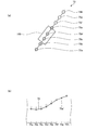
- FIG. 1 is a diagram illustrating an example of a work machine according to the present embodiment.
- FIG. 2 is a block diagram illustrating an example of a control system that is a control system for a work machine according to the present embodiment.
- FIG. 3 is a block diagram illustrating an example of the display controller.
- FIG. 4 is a diagram illustrating an example of current landform data.
- FIG. 5 is a diagram illustrating an example of a reference point.
- FIG. 6 is a diagram schematically illustrating a process of generating the composite current landform data.
- FIG. 7 is a diagram schematically illustrating a process of generating the combined current landform data.
- FIG. 8 is a diagram illustrating an example of the combined current landform data.
- FIG. 9 is a diagram showing the corresponding design terrain data, composite current terrain data, and virtual design data.
- FIG. 10 is a flowchart illustrating an example of a method for controlling the work machine according to the present embodiment.
- FIG. 1 is a diagram illustrating an example of a work machine according to the present embodiment.
- a bulldozer 100 will be described as an example of a work machine.
- the bulldozer 100 includes a vehicle main body 10 and a work machine 20.
- the bulldozer 100 is used at a work site such as a construction site or a mine.
- the X axis, Y axis, and Z axis shown in FIG. 1 indicate the X axis, Y axis, and Z axis in the global coordinate system.
- the direction in which the work implement 20 is located with respect to the vehicle body 10 is the front. Therefore, the direction in which the vehicle body 10 is located with respect to the work machine 20 is the rear.
- the direction in which the vehicle main body 10 is located with respect to the ground contact surface where the crawler belt 11a contacts the ground is defined as the upper direction, and the direction from the vehicle main body 10 toward the ground contact surface, that is, the direction of gravity is decreased.
- the bulldozer 100 is arranged with the front-rear direction aligned with the X direction, the vehicle width direction aligned with the Y direction, and the vertical direction aligned with the Z direction.
- the vehicle body 10 has a traveling device 11 as a traveling unit.
- the traveling device 11 has a crawler belt 11a.
- the crawler belts 11 a are disposed on the left and right sides of the vehicle main body 10.
- the traveling device 11 causes the bulldozer 100 to travel by rotating the crawler belt 11a with a hydraulic motor (not shown).
- the vehicle body 10 has an antenna 12.
- the antenna 12 is used to detect the current position of the bulldozer 100.
- the antenna 12 is electrically connected to the global coordinate calculation device 15.
- the global coordinate calculation device 15 is a position detection device that detects the position of the bulldozer 100.
- the global coordinate arithmetic unit 15 detects the current position of the bulldozer 100 using GNSS (Global Navigation Satellite Systems, GNSS means global navigation satellite system).
- GNSS Global Navigation Satellite Systems, GNSS means global navigation satellite system.
- the antenna 12 is appropriately referred to as a GNSS antenna 12.
- a signal corresponding to the GNSS radio wave received by the GNSS antenna 12 is input to the global coordinate calculation device 15.
- the global coordinate calculation device 15 obtains the installation position of the GNSS antenna 12 in the global coordinate system (X, Y, Z) shown in FIG.
- the global navigation satellite system is a GPS (Global Positioning System), but the global navigation satellite system is not limited to this.
- the GNSS antenna 12 is preferably installed at the upper end of the cab 13, for example.
- two GNSS antennas 12 may be arranged. In this case, it is possible to generate azimuth data using data obtained from the two GNSS antennas 12.
- the vehicle body 10 has a cab 13 provided with a driver's seat on which a driver is seated.
- a display unit 14 for displaying various operation devices and image data is arranged.
- the display unit 14 is, for example, a liquid crystal display device or the like, but is not limited thereto.
- the cab 13 is provided with an operating device (not shown).
- the operating device is a device for operating at least one of the work machine 20 and the traveling device 11.
- the work machine 20 includes a blade 21 that is a work tool, a lift frame 22 that supports the blade 21, and a lift cylinder 23 that drives the lift frame.
- the blade 21 has a cutting edge 21p.
- the cutting edge 21 p is disposed at the lower end of the blade 21. In work such as leveling work or excavation work, the blade edge 21p contacts the ground.
- the blade 21 is supported by the vehicle body 10 via the lift frame 22.
- the lift cylinder 23 connects the vehicle body 10 and the lift frame 22.
- the lift cylinder 23 drives the lift frame 22 to move the blade 21 in the vertical direction.
- the work machine 20 includes a lift cylinder sensor 23a.
- the lift cylinder sensor 23 a detects lift cylinder length data La indicating the stroke length of the lift cylinder 23.
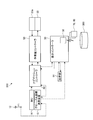
- FIG. 2 is a block diagram illustrating an example of a control system 200 that is a work machine control system according to the present embodiment.
- the control system 200 includes a global coordinate calculation device 15, an IMU (Inertial Measurement Unit) 16 that is a state detection device that detects angular velocity and acceleration, a navigation controller 40, and a display controller. 30 and a work machine controller (work machine control unit) 50.
- IMU Inertial Measurement Unit
- work machine controller work machine control unit
- the global coordinate calculation device 15 acquires reference position data P1 that is position data of the antenna 12 expressed in the global coordinate system.
- the global coordinate arithmetic unit 15 includes a processing unit that is a processor such as a CPU (Central Processing Unit) and a storage unit that is a storage device such as a RAM (Random Access Memory) and a ROM (Read Only Memory).
- the global coordinate calculation device 15 generates position data P indicating the position of the vehicle main body 10 based on the reference position data P1.
- the position data P indicates a position in the global coordinate system (X, Y, Z).
- the global coordinate calculation device 15 outputs the generated position data P to the navigation controller 40 and the display controller 30.
- the IMU 16 is a state detection device that detects operation information indicating the operation of the bulldozer 100.
- the operation information may include information indicating the attitude of the bulldozer 100.
- the information indicating the attitude of the bulldozer 100 is exemplified by the roll angle, pitch angle, and azimuth angle of the bulldozer 100.
- the IMU 16 is attached to the vehicle main body 10.
- the IMU 16 may be installed, for example, in the lower part of the cab 13.
- the IMU 16 detects the angular velocity and acceleration of the bulldozer 100. Along with the operation of the bulldozer 100, the bulldozer 100 generates various accelerations such as acceleration generated during traveling, angular acceleration generated during turning, and gravitational acceleration.
- the IMU 16 detects and outputs at least gravitational acceleration.
- the gravitational acceleration is an acceleration corresponding to a drag force against the gravity.
- the IMU 16 detects acceleration in the X-axis direction, Y-axis direction, and Z-axis direction, and angular velocities (rotational angular velocities) around the X-axis, Y-axis, and Z-axis. .
- the display controller 30 displays an image such as a guidance screen on the display unit 14.
- the display controller 30 has a communication unit 32.
- the communication unit 32 can communicate with an external communication device.
- the communication unit 32 receives the current terrain data 70 and the design terrain data 80 of the work site from, for example, the management server 300 or the like.
- the communication unit 32 may receive the current terrain data 70 and the design terrain data 80 at the work site from an external storage device such as a USB memory, a PC, or a portable terminal.
- the navigation controller 40 includes a processing unit that is a processor such as a CPU and a storage unit that is a storage device such as a RAM and a ROM.
- the navigation controller 40 receives a detection value of the global coordinate calculation device 15, a detection value of the IMU 16, and an output value from the work machine controller 50 described later.
- the navigation controller 40 obtains position information related to the position of the bulldozer 100 from the detection value of the global coordinate arithmetic unit 15 and the detection value of the IMU 16 and outputs the position information to the display controller 30.
- the navigation controller 40 receives virtual design data 81 output from the display controller 30.
- the navigation controller 40 sets a target cutting edge position of the cutting edge 21 p of the blade 21 based on the virtual design data 81 and outputs the target cutting edge position to the work machine controller 50.
- the navigation controller 40 receives cutting edge position data from the work machine controller 50.
- the cutting edge position data is data indicating a cutting edge position which is a three-dimensional position of the cutting edge 21p.
- the navigation controller 40 generates target cutting edge position data indicating the target cutting edge position based on the cutting edge position data.
- the navigation controller 40 uses the current terrain data indicating the current terrain at the work site when generating the target edge position data. For example, the navigation controller 40 generates a virtual target ground obtained by offsetting the current landform indicated by the current landform data downward by a predetermined distance, and generates target blade edge position data so that the blade edge 21p is along the virtual target ground.
- the work machine controller 50 includes a processing unit that is a processor such as a CPU and a storage unit that is a storage device such as a RAM and a ROM.
- the work machine controller 50 detects the blade edge position data using the position information of the blade 21.
- the work machine controller 50 receives the target cutting edge position output from the navigation controller 40.
- the work machine controller 50 generates and outputs a work machine command value for controlling the operation of the work machine 20 based on the target cutting edge position data.
- the work machine controller 50 receives lift cylinder length data La output from the lift cylinder sensor 23a.
- the work machine controller 50 calculates the lift angle ⁇ a (see FIG. 1) of the blade 21 based on the lift cylinder length data La.
- the lift angle ⁇ a corresponds to the descending angle of the blade 21 from the origin position, that is, the depth of penetration of the cutting edge 21p into the ground or the height from the ground.
- the origin positions of the lift frame 22 and the blade 21 are indicated by two-dot chain lines.
- the bulldozer 100 moves forward with the blade 21 lowered from the origin position, thereby performing leveling work and excavation work by the bulldozer 100.
- the work machine controller 50 outputs a signal indicating the cutting edge position and the lift angle ⁇ a regarding the current position of the cutting edge 21p to the navigation controller 40 based on the detection value of the lift cylinder sensor 23a.
- FIG. 3 is a block diagram showing an example of the navigation controller 40.
- the navigation controller 40 includes a processing unit 44 and a storage unit 45.
- the processing unit 44 and the storage unit 45 are connected via a signal property such as a bus line 46.
- the storage unit 45 stores a program and data for performing various processes in the processing unit 44.
- the storage unit 45 stores, for example, current terrain data 70, design terrain data 80, and composite current terrain data 73, which will be described later.
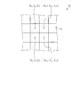
- FIG. 4 is a diagram showing an example of the current terrain data.
- the current landform data 70 is data relating to the height position (Z coordinate) for each grid region G when the work site is partitioned into a plurality of grid regions G.
- the grid area G is provided at predetermined intervals in the X direction and the Y direction of the global coordinate system. In each grid area G, position data (X, Y, Z) in the global coordinate system is accumulated.
- the current landform data 70 may be data relating to height data at an arbitrary position in the grid area G.
- the current landform data 70 may be height data at the center position of the grid area G, or four corners of the grid area G. May be the height data.
- the grid region G is set to a square, for example, but is not limited thereto, and may be another shape such as a rectangle, a parallelogram, a triangle, or the like.
- the current landform data 70 is generated by, for example, measuring the current landform at the work site using various measurement methods.
- the current terrain data 70 includes, for example, a plurality of types of current terrain data having different measurement methods.
- a measurement method for generating the current landform data 70 for example, a method of measuring the current landform using position information of a vehicle traveling on the work site, and position information of a work machine such as the bulldozer 100 traveling on the work site are used.
- the method used to measure the current terrain using a surveying vehicle the method used to survey the current terrain using a survey vehicle, the method used to measure the current terrain using a stationary surveying instrument, the method used to measure the current terrain using a stereo camera, a drone, etc.
- a method of measuring the current topography using unmanned aerial vehicles may be a method of photographing the current terrain using a camera or the like and measuring the current terrain data from the photographing result, or measuring the current terrain data using a laser scanner.
- the current terrain data 70 may be provided with identification information for identifying the measurement method and the like.
- the processing unit 44 is a processor such as a CPU, for example.
- the processing unit 44 includes an acquisition unit 62, a test unit 63, a synthesis unit 64, a generation unit 65, a display control unit 66, and a current landform data calculation unit 61.
- the current terrain data calculation unit 61 calculates the current terrain data 70 indicating the current terrain for an area where the bulldozer 100 has passed, for example, in the work site.
- the current landform data calculation unit 61 calculates the current landform data 70 based on the position information output from the global coordinate calculation device 15, for example. In this case, the current landform data calculation unit 61 calculates, for example, the Z coordinate for each grid region G corresponding to the region through which the bulldozer 100 has passed.
- the acquisition unit 62 acquires a plurality of current terrain data 70 indicating the current terrain at the work site.
- the current terrain data 70 acquired by the acquisition unit 62 includes, for example, the current terrain data 70 received from the management server 300 and the current terrain data 70 generated by the current terrain data calculation unit 61.
- the plurality of current terrain data 70 acquired by the acquisition unit 62 may differ in accuracy, range of data, etc., depending on the measurement method and the like.
- the current terrain data 70 obtained by performing measurement using vehicle position information at the work site has a low traveling accuracy at the time of measurement, and thus the measurement accuracy is low.
- the current terrain data 70 obtained by using the position information of the work machine such as the bulldozer 100 whose traveling speed is lower than that of the above-mentioned vehicle has high measurement accuracy because the traveling speed is low.
- the bulldozer 100 travels mainly in places where the bulldozer 100 performs work and places that move for work, for example, and therefore the number of grid areas G in which data exists is limited.
- the verification unit 63 performs verification of the current landform data 70 acquired by the acquisition unit 62.
- the verification unit 63 performs verification based on at least one of the acquisition time of the current landform data 70 and the accuracy of the current landform data 70.
- the verification unit 63 adopts the current landform data 70 that satisfies a predetermined standard, and discards the current landform data 70 that does not satisfy the predetermined standard, based on the test result. In addition, the test
- the synthesizing unit 64 generates the composite current terrain data 73.
- the composite current landform data 73 is current landform data indicating the current landform of a predetermined reference point in the work site.
- FIG. 5 is a diagram illustrating an example of a reference point.
- the bulldozer 100 is schematically shown by a rectangle.
- the reference points 75 are a plurality of points set corresponding to the traveling direction of the traveling device 11 of the bulldozer 100.
- Each reference point 75 is set in a linear direction forward and backward in the traveling direction with the current position of the bulldozer 100 as a reference.
- the set number of each reference point 75 and the interval between the reference points 75 are arbitrary. Therefore, for example, the reference points 75 may be set at equal intervals as described in FIG. In addition, the number of reference points 75 set may be equal or different between the front and the rear of the current position.
- the plurality of reference points 75 are set based on position information output from the global coordinate calculation device 15.
- the reference point 75 is not limited to the above, and may be set at any position.
- the X coordinate and the Y coordinate at each reference point 75 are obtained based on the position information of the bulldozer 100 and the direction information of the bulldozer 100.
- the combining unit 64 When generating the combined current landform data 73, the combining unit 64 combines the position data corresponding to or at the same position of the plurality of current landform data 70 based on a predetermined rule to generate one combined current landform data 73. To do. As an example of the present embodiment, a case where the combined current landform data 73 is generated using the reference point 75 will be described below. First, the combining unit 64 is based on position data (X, Y, Z) in each grid region G in one current landform data 70 and position data (X, Y) in the X direction and the Y direction at the reference point 75.
- the height data (Z coordinate) at the reference point 75 is obtained.
- the compositing unit 64 for the reference point 75 for which the Z coordinate is to be obtained, based on the coordinates (X, Y, Z) of the grid region G (for example, four) around the reference point 75, for example, Calculate the Z coordinate by linear interpolation.
- Such processing is performed for each reference point 75, and a set of Z coordinates of each reference point 75 (hereinafter referred to as partial current landform data) is calculated.
- the partial current landform data is an example of the current landform data.
- the current terrain data 70 obtained by measuring the current terrain using the position information of the work machine such as the bulldozer 100 among the plurality of types of current terrain data 70 is used as the first current terrain data 71 by the combining unit 64.
- the position data is calculated for the grid area G in which the bulldozer 100 travels and the data exists, but the position data does not exist for the grid area G in which the bulldozer 100 does not travel.
- the grid area G in which position data exists is defined as an effective grid area G1
- the grid area G in which position data does not exist is defined as an invalid grid area G2.
- FIG. 6A shows that the grid area G through which the bulldozer 100 has passed is an effective grid area G1, and the grid area G through which the bulldozer 100 has not passed is an invalid grid area G2.
- the synthesizer 64 calculates the Z coordinate of each reference point 75 within a range that can be calculated using the position information in the effective grid region G1. As shown in FIG. 6A, the combining unit 64 uses the position data of the effective grid region G1 for the reference points 75 (75a, 75b, 75c, 75d, and 75e) that exist in the vicinity of the effective grid region G1. To calculate the Z coordinate.
- the combining unit 64 does not calculate the Z coordinate for the reference point 75 (75f, 75g, 57h) that exists in the vicinity of the invalid grid region G2 that does not have the position data in FIG.
- the synthesizing unit 64 generates a set of position information of the reference points 75a, 75b, 75c, 75d, and 75e as the first partial current landform data 71.
- FIG. 6B shows the Z coordinate of each reference point 75 in the first partial current topographic data 71.
- height data exists at the reference points 75a, 75b, 75c, 75d, and 75e for which the Z coordinate is obtained, height data is provided for the reference points 75f, 75g, and 57h for which the Z coordinate is not obtained. Does not exist.
- FIG. 7A shows an example when a part of data is discarded by the test unit 63, for example.
- the synthesizer 64 treats the discarded grid area G as an invalid grid area G4 in which no data exists. Therefore, in the case illustrated in FIG. 7A, the combining unit 64 calculates the Z coordinate of the reference point 75 within a range that can be calculated using position information in the vicinity of the effective grid region G3. As shown in FIG.
- the combining unit 64 performs the effective grid region G3 for the reference points 75 (75a, 75b, 75c, 75d, 75e, 75f, and 57h) that exist in the vicinity of the effective grid region G3.
- the Z coordinate is calculated using the position information.
- the combining unit 64 does not calculate the Z coordinate for the reference point 75g existing in the vicinity of the invalid grid region G4.
- the synthesizing unit 64 generates a set of position information of the reference points 75 a, 75 b, 75 c, 75 d, 75 e, 75 f, 57 h as the second partial current landform data 72.
- FIG. 7B shows the Z coordinate of each reference point 75 in the second partial current terrain data 72.
- height data exists at the reference points 75a, 75b, 75c, 75d, 75e, 75f, and 57h for which the Z coordinate is obtained, height data is provided for the reference point 75g for which the Z coordinate is not obtained. Does not exist.
- the Z coordinate does not exist in the first partial current topographic data 71 and the second partial current topographic data 72 for the reference point 75g.
- the synthesis unit 64 complements the position information of the invalid grid area G4 by a method such as linear interpolation based on the position information of the effective grid area G3 arranged around the invalid grid area G4. Also good.
- combination part 64 can calculate the Z coordinate of the reference point 75g using the positional infomation on the said effective grid area
- the combining unit 64 calculates two types of partial current topographic data, that is, the first partial current topographic data 71 and the second partial current topographic data 72 has been described as an example. Is not to be done.
- the synthesis unit 64 may calculate three or more types of partial present landform data. Further, the synthesis unit 64 may obtain partial current landform data from the current landform data 70 obtained by a different type or a different measurement method.
- the synthesizing unit 64 calculates a plurality of partial current topographic data, and then combines the data included in each partial current topographic data to generate composite current topographic data.
- the synthesizing unit 64 synthesizes based on, for example, a predetermined rule.
- a predetermined rule for example, there is a priority order set in advance for each current landform data 70.
- the compositing unit 64 preferentially adopts the Z coordinate of each reference point 75 of the partial current landform data 70 calculated from the current landform data 70 having a high priority. It is good also as composition to do.
- This priority order is set for each measurement method of the current landform data 70, for example. For example, the priority order may be set low for the current landform data 70 obtained by a measurement method with low accuracy.
- FIG. 8A is a diagram showing an example of the combined current terrain data 73.
- the combining unit 64 combines the height data of the first partial current landform data 71 and the second partial current landform data 72 for each reference point 75 based on a predetermined rule, for example, as shown in FIG.
- a predetermined rule height data for each reference point 75 is obtained based on the priority set for each current landform data 70, that is, from any partial current landform data 71, 72.
- a case where the rule of extracting height data is adopted will be described.
- a case where the first current landform data (first partial current landform data) 71 has a higher priority than the second current landform data (second partial current landform data) 72 will be described as an example.
- the combined current landform data 73 is based on the rule that the first current landform data (first partial current landform data) 71 has priority over the second current landform data (second partial current landform data) 72. 75c, 75d, and 75e, height data is extracted from the first partial current topographic data 71. Further, the combined current landform data 73 is extracted from the second partial current landform data 72 at the reference points 75f and 75h. The reference point 75g does not have Z coordinate data.
- FIG. 8 (b) shows the Z coordinate of each reference point 75 in the combined current landform data 73.
- the broken line height data at the reference points 75a, 75b, 75c, 75d, and 75e is the height data in the second partial current landform data 72 that has not been adopted because of the low priority.
- the height data of the reference point 75g may be acquired based on the position information obtained by complementing the invalid grid G4 in the second partial current terrain data 72 as described above. Further, for example, as shown at the reference point 75g ′ in FIG. 8B, the height data of the reference point 75g may be obtained by linear interpolation from the height data of the reference point 75f and the reference point 75h.
- the generation unit 65 generates virtual design data 81 for the work site based on the combined current terrain data 73 generated by the combining unit 64.
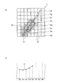
- FIG. 9 is a diagram showing the design terrain data 80, the combined current terrain data 73 at each reference point 75 shown in FIG. 8, and the virtual design data 81 in association with each other.
- the design landform data 80 means the final target surface at the construction site.
- the virtual design data 81 is design data indicating an intermediate design landform for reaching the design landform from the current landform at the work site.
- the intermediate design terrain is a target terrain set so that the bulldozer 100 is reached by one or several excavation operations, for example.
- the virtual design data 81 is a value between the combined current terrain data 73 and the designed terrain data 80.
- the virtual design data 81 is formed by offsetting the combined current terrain data 73 downward in the Z coordinate. May be.
- the virtual design data 81 may be formed, for example, in a shape in which the current landform is smoothed and then offset downward in the Z coordinate.
- FIG. 10 is a flowchart showing an example of a method for controlling the work machine according to the present embodiment.
- the acquisition unit 62 of the display controller 30 acquires a plurality of current terrain data 70 stored in the storage unit 35.
- current terrain data 70 as described above, for example, the current terrain data 70 obtained by measuring the current terrain using the position information of the vehicle and the position information of the work machine such as the bulldozer 100 are used.
- Current terrain data 70 obtained by measuring the current terrain data 70 obtained by running a survey vehicle and surveying the current terrain, and current terrain obtained by surveying the current terrain using a stationary surveying instrument Data 70, a method of measuring the current terrain using a stereo camera, and the current terrain data 70 obtained by photographing the current terrain with an unmanned air vehicle such as a drone and obtaining the current terrain from the photographing result.
- the verification unit 63 may perform verification processing on the acquired current landform data 70.
- step ST20 the compositing unit 64 generates, for example, partial current terrain data that is a set of Z coordinates of each reference point 75 based on the position information of the grid region G for the acquired plural types of current terrain data 70. calculate.
- step ST30 the synthesizing unit 64 synthesizes data included in each partial current terrain data based on a predetermined rule to generate synthesized current terrain data.
- the combining unit 64 stores the generated combined current landform data 73 in the storage unit 35.
- step ST ⁇ b> 40 the generation unit 65 generates virtual design data 81 based on the combined current landform data 73 stored in the storage unit 35.
- step ST50 the navigation controller 40 and the work machine controller 50 control the work machine 20 based on the generated virtual design data 81.
- the navigation controller 40 sets the target cutting edge position of the cutting edge 21p of the blade 21 based on the generated virtual design data 81 and outputs the target cutting edge position to the work machine controller 50.
- the work machine controller 50 outputs a work machine command value that controls the operation of the work machine 20 based on the value of the target cutting edge position output from the navigation controller 40. As described above, the operation of the work machine 20 is controlled based on the virtual design data 81.
- the work machine control system is acquired by the acquisition unit 62 that acquires a plurality of current landform data 70 indicating the current landform of the work site where the bulldozer 100 performs work, and is acquired by the acquisition unit 62.
- a synthesizing unit 64 that generates the combined current topographic data 73 of the work site based on a plurality of current topographic data 70 based on a predetermined rule.
- the work machine control method according to the present embodiment acquires a plurality of current landform data 70 indicating the current landform of the work site where the bulldozer 100 performs work, and is based on the acquired plurality of current landform data 70.
- the work machine control system 200 further includes a generation unit 65 that generates the virtual design data 81 of the work site based on the combined current terrain data 73 and the design terrain data 80 indicating the design terrain of the work site. Prepare. According to this configuration, since the virtual design data 81 is generated based on the combined current terrain data 73, the work implement 20 can be controlled using the highly accurate virtual design data 81.
- each process executed by the navigation controller 40 may be executed by the display controller 30, the work machine controller 50, or a controller other than these.
- the bulldozer 100 has been described as an example of the work machine.
- the present invention is not limited to this, and other work machines such as a hydraulic excavator or a wheel loader may be used.
- the control system 200 in the above embodiment may be provided in a work machine such as the bulldozer 100, may be provided in the management server 300, or the work machine and the management server may be shared.
- the current landform data 70 the first current landform data measured using the position information of the work machine such as the bulldozer 100 and the second current landform data measured using the vehicle position information.
- the present invention is not limited to this.
- a survey result using a surveying instrument or a detection result when a current landform is detected using an unmanned air vehicle such as a drone may be used.
- generates the synthetic present terrain data 73 is not limited to this.
- the synthesis unit 64 calculates the average value or median value of the height data (Z coordinate) at a certain position (X, Y coordinate) in the first partial current topographic data 71 and the second partial current topographic data 72. The result may be adopted as the combined current terrain data 73.
- the synthesis unit 64 may use the result of weighted averaging of the first partial current landform data 71 and the second partial current landform data 72 based on a predetermined condition as the combined current landform data 73. Further, the combining unit 64 may adopt, for example, data having the lowest Z coordinate or data having the highest Z coordinate for each corresponding position (X, Y coordinate) in the plurality of partial current landform data to obtain the combined current landform data 73. . Further, accuracy information included in the GNSS radio wave, information (measurement method information) indicating the method of measuring the current landform data 70, or time information indicating the time when the current landform data 70 is measured are stored in the current landform data 70.
- the combined current landform data 73 may be obtained by prioritizing or weighted average based on the accuracy information and the measurement method information. Further, for example, measurement method information is assigned to each of a plurality of current landform data 70, and the combining unit 64 generates the combined current landform data 73 based on a priority order or a weighted average according to a predetermined measurement method. You may make it do. Further, according to each measurement method of the current landform data 70, for example, priority order or numerical accuracy information may be set.
- the accuracy may vary depending on the accuracy of various sensors and the calculation algorithm. Therefore, measurement method information or accuracy information may be added to the current landform data 70 in accordance with the accuracy and calculation algorithm of various sensors.
- the compositing unit 64 generates the combined current landform data 73 using the partial current landform data 71 and 72.
- the synthesizing unit 64 may synthesize a plurality of current terrain data 70 according to a predetermined rule without using the partial current terrain data, and obtain the combined current terrain data 73.
- the synthesizing unit 64 may synthesize a plurality of current terrain data 70 in that state without calculating the partial current terrain data from the current terrain data 70, and obtain the combined current terrain data 73.
- the composition unit 64 replaces each reference point 75 with the position where the height data exists in the composite current landform data 73 so that the position of the point having the position information in the grid region G is the position of the composite current landform data 73. May be generated.
- the combined current terrain data is a set of position data at a specific point such as the reference point 75.
- the present invention is not limited to this.
- the composite current terrain data may be a collection of position data in some or all areas of the work site.
- G Grid area G1, G3 Effective grid area G2, G4 Invalid grid area 10 Vehicle body 11 Traveling device 11a Crawler belt 12 Antenna 20 Work machine 21 Blade 21p Cutting edge 30 Display controller 40
- Navigation controller 50 Work machine controller 61 Acquisition of current terrain data calculation unit 62
- Unit 63 verification unit 64 compositing unit 65
- generating unit 66 display control unit 70 current terrain data 71 first partial current terrain data 72 second partial current terrain data 73 composite current terrain data 75, 75a, 75b, 75c, 75d, 75e, 75f 75g, 75h Reference point 80
Abstract
Description
G1、G3 有効グリッド領域
G2、G4 無効グリッド領域
10 車両本体
11 走行装置
11a 履帯
12 アンテナ
20 作業機
21 ブレード
21p 刃先
30 表示コントローラ
40 ナビゲーションコントローラ
50 作業機コントローラ
61 現況地形データ算出部
62 取得部
63 検定部
64 合成部
65 生成部
66 表示制御部
70 現況地形データ
71 第1部分現況地形データ
72 第2部分現況地形データ
73 合成現況地形データ
75,75a,75b,75c,75d,75e,75f,75g,75h 参照地点
80 設計地形データ
81 仮想設計データ
100 ブルドーザ
200 制御システム
300 管理サーバ G Grid area G1, G3 Effective grid area G2, G4
Claims (7)
- 作業機械が作業を行う作業現場の現況地形を示す複数の現況地形データを取得する取得部と、
前記取得部で取得された複数の前記現況地形データに基づいて、所定の規則に基づいて前記作業現場の合成現況地形データを生成する合成部と
を備える作業機械の制御システム。 An acquisition unit for acquiring a plurality of current terrain data indicating a current terrain of a work site where the work machine performs work;
A work machine control system comprising: a synthesis unit that generates, based on a plurality of the current terrain data acquired by the acquisition unit, a combined current terrain data of the work site based on a predetermined rule. - 前記合成部は、前記取得部で取得された複数の前記現況地形データにおける測定手法情報又は精度情報に基づいて、前記作業現場の合成現況地形データを生成する、
請求項1に記載の作業機械の制御システム。 The combining unit generates combined current landform data of the work site based on measurement method information or accuracy information in the plurality of current landform data acquired by the acquisition unit,
The work machine control system according to claim 1. - 前記合成部は、優先順位又は重み付け平均を用いて前記作業現場の合成現況地形データを生成する、
請求項1又は2に記載の作業機械の制御システム。 The combining unit generates the combined current terrain data of the work site using a priority order or a weighted average.
The work machine control system according to claim 1 or 2. - 前記合成現況地形データに基づいて前記作業機を制御する作業機制御部を更に備える
請求項1~3のいずれか一項に記載の作業機械の制御システム。 The work machine control system according to any one of claims 1 to 3, further comprising a work machine control unit configured to control the work machine based on the combined current landform data. - 前記合成現況地形データは、前記現況地形データの一部である部分現況地形データに基づいて生成される
請求項1~4のいずれか一項に記載の作業機械の制御システム。 The work machine control system according to any one of claims 1 to 4, wherein the composite current landform data is generated based on partial current landform data that is a part of the current landform data. - 前記合成部は、前記取得部で取得された複数の前記現況地形データにおける高さデータを比較し、最も高い又は最も低い前記高さデータを抽出することにより、前記作業現場の合成現況地形データを生成する、
請求項1に記載の作業機械の制御システム。 The synthesizing unit compares the height data in the plurality of current terrain data acquired by the acquisition unit, and extracts the highest or lowest height data, thereby obtaining the combined current terrain data of the work site. Generate,
The work machine control system according to claim 1. - 作業機械が作業を行う作業現場の現況地形を示す複数の現況地形データを取得することと、
取得された複数の前記現況地形データに基づいて、所定の規則に基づいて前記作業現場の合成現況地形データを生成することと
を含む作業機械の制御方法。 Obtaining a plurality of current terrain data indicating the current terrain of the work site where the work machine performs the work;
Generating a composite current topographical data of the work site based on a predetermined rule based on the plurality of acquired current topographical data.
Priority Applications (4)
| Application Number | Priority Date | Filing Date | Title |
|---|---|---|---|
| JP2017504197A JP6289731B2 (en) | 2017-01-13 | 2017-01-13 | Work machine control system, work machine control method, and navigation controller |
| US15/526,104 US10731322B2 (en) | 2017-01-13 | 2017-01-13 | Work machine control system and work machine control method |
| CN201780000283.1A CN107002384B (en) | 2017-01-13 | 2017-01-13 | Control system for work machine and control method for work machine |
| PCT/JP2017/001142 WO2017115879A1 (en) | 2017-01-13 | 2017-01-13 | Work machine control system and work machine control method |
Applications Claiming Priority (1)
| Application Number | Priority Date | Filing Date | Title |
|---|---|---|---|
| PCT/JP2017/001142 WO2017115879A1 (en) | 2017-01-13 | 2017-01-13 | Work machine control system and work machine control method |
Publications (1)
| Publication Number | Publication Date |
|---|---|
| WO2017115879A1 true WO2017115879A1 (en) | 2017-07-06 |
Family
ID=59225314
Family Applications (1)
| Application Number | Title | Priority Date | Filing Date |
|---|---|---|---|
| PCT/JP2017/001142 WO2017115879A1 (en) | 2017-01-13 | 2017-01-13 | Work machine control system and work machine control method |
Country Status (4)
| Country | Link |
|---|---|
| US (1) | US10731322B2 (en) |
| JP (1) | JP6289731B2 (en) |
| CN (1) | CN107002384B (en) |
| WO (1) | WO2017115879A1 (en) |
Cited By (2)
| Publication number | Priority date | Publication date | Assignee | Title |
|---|---|---|---|---|
| JP2019039279A (en) * | 2017-08-29 | 2019-03-14 | 株式会社小松製作所 | Control system of work vehicle, method, and work vehicle |
| DE112021001043T5 (en) | 2020-04-14 | 2023-03-09 | Komatsu Ltd. | BUILDING PROCESS AND SYSTEM |
Families Citing this family (6)
| Publication number | Priority date | Publication date | Assignee | Title |
|---|---|---|---|---|
| US10684137B2 (en) * | 2017-11-29 | 2020-06-16 | Deere & Company | Work site monitoring system and method |
| CN108301450A (en) * | 2018-03-14 | 2018-07-20 | 上海宝冶集团南京建筑有限公司 | A kind of construction forklift of the mating unmanned plane in construction site |
| US11761173B2 (en) * | 2018-06-26 | 2023-09-19 | Caterpillar Inc. | Systems and methods for building a pad |
| JP7330458B2 (en) * | 2019-07-02 | 2023-08-22 | 住友建機株式会社 | Excavators and controls for excavators |
| CN113031034A (en) * | 2021-02-18 | 2021-06-25 | 农芯科技(广州)有限责任公司 | Land leveling method and system suitable for complex target curved surface |
| CN113235681B (en) * | 2021-05-17 | 2022-05-20 | 山推工程机械股份有限公司 | Unmanned bulldozer operation method and device, bulldozer and medium |
Citations (4)
| Publication number | Priority date | Publication date | Assignee | Title |
|---|---|---|---|---|
| JPH09230039A (en) * | 1996-02-27 | 1997-09-05 | Mitsubishi Electric Corp | Interference synthetic aperture radar equipment and terrain height measuring method using the synthetic aperture radar equipment |
| JP2006235646A (en) * | 2006-05-12 | 2006-09-07 | Hitachi Ltd | 3-dimensional map display device |
| WO2015194601A1 (en) * | 2014-06-20 | 2015-12-23 | 住友重機械工業株式会社 | Shovel and method for controlling same |
| JP2017004373A (en) * | 2015-06-12 | 2017-01-05 | 株式会社リコー | Information processing device, information processing program, and information processing system |
Family Cites Families (15)
| Publication number | Priority date | Publication date | Assignee | Title |
|---|---|---|---|---|
| EP1541772B1 (en) * | 2002-09-17 | 2015-08-05 | Hitachi Construction Machinery Co., Ltd. | Excavation teaching apparatus for construction machine |
| US20050283294A1 (en) * | 2004-06-16 | 2005-12-22 | Lehman Allen A Jr | Method and apparatus for machine guidance at a work site |
| US8351684B2 (en) | 2008-02-13 | 2013-01-08 | Caterpillar Inc. | Terrain map updating system |
| WO2011120152A1 (en) * | 2010-03-31 | 2011-10-06 | Ambercore Software Inc. | System and method for extracting features from data having spatial coordinates |
| JP5202667B2 (en) * | 2011-02-22 | 2013-06-05 | 株式会社小松製作所 | Hydraulic excavator position guidance system and control method thereof |
| US8755977B2 (en) * | 2012-09-21 | 2014-06-17 | Siemens Industry, Inc. | Method and system for preemptive load weight for mining excavating equipment |
| US8965642B2 (en) * | 2012-10-05 | 2015-02-24 | Komatsu Ltd. | Display system of excavating machine and excavating machine |
| JP5789279B2 (en) | 2013-04-10 | 2015-10-07 | 株式会社小松製作所 | Excavation machine construction management device, hydraulic excavator construction management device, excavation machine and construction management system |
| US9540793B2 (en) | 2014-05-30 | 2017-01-10 | Komatsu Ltd. | Work machine control system, work machine, and work machine control method |
| US9766460B2 (en) * | 2014-07-25 | 2017-09-19 | Microsoft Technology Licensing, Llc | Ground plane adjustment in a virtual reality environment |
| CN104619920B (en) | 2014-09-10 | 2016-09-28 | 株式会社小松制作所 | Working truck |
| EP3086196B1 (en) * | 2015-04-21 | 2017-04-05 | Hexagon Technology Center GmbH | Method and control system for surveying and mapping a terrain while operating a bulldozer |
| JP6496182B2 (en) * | 2015-04-28 | 2019-04-03 | 株式会社小松製作所 | Construction planning system |
| AU2016283735A1 (en) * | 2015-06-23 | 2017-12-21 | Komatsu Ltd. | Construction management system and construction management method |
| JP6545609B2 (en) * | 2015-12-04 | 2019-07-17 | 日立建機株式会社 | Control device of hydraulic construction machine |
-
2017
- 2017-01-13 WO PCT/JP2017/001142 patent/WO2017115879A1/en active Application Filing
- 2017-01-13 JP JP2017504197A patent/JP6289731B2/en active Active
- 2017-01-13 CN CN201780000283.1A patent/CN107002384B/en active Active
- 2017-01-13 US US15/526,104 patent/US10731322B2/en active Active
Patent Citations (4)
| Publication number | Priority date | Publication date | Assignee | Title |
|---|---|---|---|---|
| JPH09230039A (en) * | 1996-02-27 | 1997-09-05 | Mitsubishi Electric Corp | Interference synthetic aperture radar equipment and terrain height measuring method using the synthetic aperture radar equipment |
| JP2006235646A (en) * | 2006-05-12 | 2006-09-07 | Hitachi Ltd | 3-dimensional map display device |
| WO2015194601A1 (en) * | 2014-06-20 | 2015-12-23 | 住友重機械工業株式会社 | Shovel and method for controlling same |
| JP2017004373A (en) * | 2015-06-12 | 2017-01-05 | 株式会社リコー | Information processing device, information processing program, and information processing system |
Cited By (3)
| Publication number | Priority date | Publication date | Assignee | Title |
|---|---|---|---|---|
| JP2019039279A (en) * | 2017-08-29 | 2019-03-14 | 株式会社小松製作所 | Control system of work vehicle, method, and work vehicle |
| US11512452B2 (en) | 2017-08-29 | 2022-11-29 | Komatsu Ltd. | Control system for work vehicle, method, and work vehicle |
| DE112021001043T5 (en) | 2020-04-14 | 2023-03-09 | Komatsu Ltd. | BUILDING PROCESS AND SYSTEM |
Also Published As
| Publication number | Publication date |
|---|---|
| CN107002384B (en) | 2020-06-09 |
| JP6289731B2 (en) | 2018-03-07 |
| JPWO2017115879A1 (en) | 2017-12-28 |
| US10731322B2 (en) | 2020-08-04 |
| CN107002384A (en) | 2017-08-01 |
| US20180202128A1 (en) | 2018-07-19 |
Similar Documents
| Publication | Publication Date | Title |
|---|---|---|
| JP6289731B2 (en) | Work machine control system, work machine control method, and navigation controller | |
| WO2017119517A1 (en) | Working-machine control system, working machine, and working-machine control method | |
| AU2021201894B2 (en) | Shape measuring system and shape measuring method | |
| WO2017061518A1 (en) | Construction management system, construction management method and management device | |
| JP6674846B2 (en) | Shape measuring system, work machine and shape measuring method | |
| JP7203616B2 (en) | working machine | |
| KR20170039612A (en) | Calibration system, work machine, and calibration method | |
| JP2018162631A (en) | Construction machine | |
| JP2018059400A (en) | Construction management system | |
| JP6553702B2 (en) | Work machine control system, work machine, work machine control method and navigation controller | |
| JP6815462B2 (en) | Shape measurement system and shape measurement method | |
| WO2017061512A1 (en) | Work-performing method, control system for work machine, and work machine | |
| JP6905007B2 (en) | Work machine control system, work machine, work machine control method and navigation controller | |
| JP7263287B2 (en) | working machine | |
| WO2021210427A1 (en) | Construction method and construction system | |
| JP2023012798A (en) | Work machine | |
| JP6987808B2 (en) | Excavator | |
| JP7065002B2 (en) | Work machine | |
| JP7009590B1 (en) | Construction machinery | |
| JP2022129500A (en) | Topography information management system, and work machine | |
| JP2024050354A (en) | Construction machine construction accuracy prediction calculation device | |
| JP2022027816A (en) | Shovel and landform detecting system for the same |
Legal Events
| Date | Code | Title | Description |
|---|---|---|---|
| ENP | Entry into the national phase |
Ref document number: 2017504197 Country of ref document: JP Kind code of ref document: A |
|
| WWE | Wipo information: entry into national phase |
Ref document number: 15526104 Country of ref document: US |
|
| 121 | Ep: the epo has been informed by wipo that ep was designated in this application |
Ref document number: 17733937 Country of ref document: EP Kind code of ref document: A1 |
|
| NENP | Non-entry into the national phase |
Ref country code: DE |
|
| 122 | Ep: pct application non-entry in european phase |
Ref document number: 17733937 Country of ref document: EP Kind code of ref document: A1 |