WO2017109918A1 - Image processing device, image processing method, and image processing program - Google Patents
Image processing device, image processing method, and image processing program Download PDFInfo
- Publication number
- WO2017109918A1 WO2017109918A1 PCT/JP2015/086126 JP2015086126W WO2017109918A1 WO 2017109918 A1 WO2017109918 A1 WO 2017109918A1 JP 2015086126 W JP2015086126 W JP 2015086126W WO 2017109918 A1 WO2017109918 A1 WO 2017109918A1
- Authority
- WO
- WIPO (PCT)
- Prior art keywords
- image
- image processing
- target
- input
- generation unit
- Prior art date
Links
Images


Classifications
-
- G—PHYSICS
- G06—COMPUTING; CALCULATING OR COUNTING
- G06T—IMAGE DATA PROCESSING OR GENERATION, IN GENERAL
- G06T15/00—3D [Three Dimensional] image rendering
- G06T15/10—Geometric effects
- G06T15/20—Perspective computation
-
- G—PHYSICS
- G06—COMPUTING; CALCULATING OR COUNTING
- G06T—IMAGE DATA PROCESSING OR GENERATION, IN GENERAL
- G06T7/00—Image analysis
- G06T7/60—Analysis of geometric attributes
-
- G—PHYSICS
- G06—COMPUTING; CALCULATING OR COUNTING
- G06T—IMAGE DATA PROCESSING OR GENERATION, IN GENERAL
- G06T11/00—2D [Two Dimensional] image generation
- G06T11/80—Creating or modifying a manually drawn or painted image using a manual input device, e.g. mouse, light pen, direction keys on keyboard
-
- G—PHYSICS
- G06—COMPUTING; CALCULATING OR COUNTING
- G06T—IMAGE DATA PROCESSING OR GENERATION, IN GENERAL
- G06T17/00—Three dimensional [3D] modelling, e.g. data description of 3D objects
- G06T17/10—Constructive solid geometry [CSG] using solid primitives, e.g. cylinders, cubes
-
- G—PHYSICS
- G06—COMPUTING; CALCULATING OR COUNTING
- G06T—IMAGE DATA PROCESSING OR GENERATION, IN GENERAL
- G06T19/00—Manipulating 3D models or images for computer graphics
- G06T19/20—Editing of 3D images, e.g. changing shapes or colours, aligning objects or positioning parts
-
- G—PHYSICS
- G06—COMPUTING; CALCULATING OR COUNTING
- G06T—IMAGE DATA PROCESSING OR GENERATION, IN GENERAL
- G06T5/00—Image enhancement or restoration
- G06T5/50—Image enhancement or restoration by the use of more than one image, e.g. averaging, subtraction
-
- G—PHYSICS
- G06—COMPUTING; CALCULATING OR COUNTING
- G06T—IMAGE DATA PROCESSING OR GENERATION, IN GENERAL
- G06T7/00—Image analysis
- G06T7/0002—Inspection of images, e.g. flaw detection
- G06T7/0004—Industrial image inspection
-
- G—PHYSICS
- G06—COMPUTING; CALCULATING OR COUNTING
- G06T—IMAGE DATA PROCESSING OR GENERATION, IN GENERAL
- G06T2207/00—Indexing scheme for image analysis or image enhancement
- G06T2207/20—Special algorithmic details
- G06T2207/20081—Training; Learning
-
- G—PHYSICS
- G06—COMPUTING; CALCULATING OR COUNTING
- G06T—IMAGE DATA PROCESSING OR GENERATION, IN GENERAL
- G06T2219/00—Indexing scheme for manipulating 3D models or images for computer graphics
- G06T2219/20—Indexing scheme for editing of 3D models
- G06T2219/2004—Aligning objects, relative positioning of parts
Definitions
- the present invention relates to an image processing apparatus, an image processing method, and an image processing program.
- the image processing algorithm was generated by a person with specialized skills on a trial and error basis based on knowledge and experience.
- a technique for automatically generating an image processing program having a target function by using an optimization method such as a genetic algorithm, genetic programming, or SA (Simulated Annealing) has been developed.
- learning using an input image and a processing result (for example, a target image) is performed.
- a processing result for example, a target image
- an image processing program generated by combining a partial program for example, an image filter program for image processing using an input image and its processing result is optimized. Is done.
- the following information processing apparatus has been proposed that generates a learning image to be given to a discriminator in order to learn a discriminator that estimates the posture of the target object.
- This information processing apparatus sets at least one viewpoint to the shape model of the target object, and when the shape model is observed from this viewpoint, the shape is determined from this viewpoint when the viewpoint and the shape model satisfy a predetermined condition.
- An image of a shape model viewed from the model is used as a learning image.
- a target image used for automatic generation of an image processing program is generated, for example, by subjecting a corresponding input image to image processing such as retouching by an operator's operation.
- image processing such as retouching by an operator's operation.
- a highly accurate target image cannot be generated depending on the skill and personality of the operator, and as a result, the accuracy of image processing using the generated image processing program decreases.
- an input image can be obtained by changing an imaging parameter and surrounding environmental conditions variously for an object including a characteristic part that is an object of image recognition. For this reason, there are various ways of capturing the characteristic part depending on the input image, and the position of the characteristic part cannot often be accurately specified by the operator. As a result, a highly accurate target image cannot be generated.
- an object of the present invention is to provide an image processing apparatus, an image processing method, and an image processing program capable of generating a highly accurate target image.
- an image processing apparatus having an input image generation unit and a target image generation unit.
- the input image generation unit generates a virtual captured image when an object is imaged in the virtual space, and outputs the virtual captured image as an input image for generating an image processing program by learning.
- the target image generation unit receives selection of feature data corresponding to a feature part in the target object from shape data indicating the three-dimensional shape of the target object, and calculates a projection position of the feature part in the input image based on the feature data Then, a target image corresponding to the input image is generated based on the projection position.
- an image processing method in which processing similar to that of the above-described image processing apparatus is executed by a computer. Furthermore, in one proposal, an image processing program that causes a computer to execute the same processing as that of the above-described image processing apparatus is provided.
- FIG. 1 is a diagram illustrating a configuration example and a processing example of an image processing apparatus according to a first embodiment. It is a figure which shows the hardware structural example of the program generation apparatus which concerns on 2nd Embodiment. It is a block diagram which shows the example of the processing function of a program generation apparatus. It is a figure which shows the example of the image process implement
- FIG. 1 is a diagram illustrating a configuration example and a processing example of the image processing apparatus according to the first embodiment.
- An image processing apparatus 1 shown in FIG. 1 is an apparatus that generates an input image and a target image for generating an image processing program by learning.
- the image processing apparatus 1 includes an input image generation unit 1a and a target image generation unit 1b.
- the processing of the input image generation unit 1a and the target image generation unit 1b is realized by, for example, a processor included in the image processing device 1 executing a predetermined program.
- the input image generation unit 1a outputs a virtual captured image when the object 3 is captured in the three-dimensional virtual space 2 as an input image.
- the input image 11 a is generated by virtually imaging the object 3 from the camera 4 a installed in the virtual space 2.
- the input image 11b is produced
- the object 3 is shown in a state of facing different directions. Note that at least one input image may be generated.
- the target image generation unit 1b can refer to the shape data 1c indicating the three-dimensional shape of the object 3.
- the shape data 1c includes, for example, three-dimensional coordinates of a plurality of parts of the object 3 in the virtual space 2.
- the shape data 1c is stored, for example, in the storage unit 1d included in the image processing apparatus 1.
- the storage unit 1d is implemented as a storage area of a storage device included in the image processing apparatus 1.
- the target image generation unit 1b accepts selection of feature data corresponding to the feature part 3a in the object 3 from the shape data 1c.
- the characteristic part 3a is a part extracted from the image by the generated image processing program, for example.
- the feature data is selected as follows, for example.
- the target image generation unit 1b receives selection of vertex data corresponding to the characteristic part 3a among polygon vertices representing the shape of the object 3.
- the target image generation unit 1b displays a polygon model representing the shape of the object 3 as a combination of a plurality of polygons on a display device (not shown), and from among the vertices on the polygon model, The selection of the vertex corresponding to 3a is accepted.
- the target image generation unit 1b extracts data about the selected vertex from the shape data 1c as feature data.
- the characteristic part 3 a is a straight edge on the object 3. Then, a plurality of vertices 5a to 5c existing on the edge are selected from the polygon model of the object 3. In this case, the feature data corresponding to the feature part 3a is selected as a three-dimensional coordinate group of the vertices 5a to 5c, for example.
- desired shape data may be selected as feature data from a list of shape data respectively corresponding to portions that can be selected as the feature portion 3a.
- selectable parts include vertices, line segments, and polygons.
- the target image generation unit 1b calculates the projection position of the feature part 3a in the generated input image 11a based on the feature data.
- the target image generation unit 1b generates a target image 12a corresponding to the input image 11a based on the calculated projection position.
- the target image generation unit 1b calculates the projection position of the feature part 3a in the generated input image 11b based on the feature data.
- the target image generation unit 1b generates a target image 12b corresponding to the input image 11b based on the calculated projection position.
- the target image generating unit 1b converts the three-dimensional coordinates of the vertices 5a to 5c into projection coordinates when the vertices 5a to 5c are projected onto the input image 11a, and the region of the characteristic part 3a is converted based on the projected coordinates.
- the drawn target image 12a is generated.
- the feature region 3a is drawn at the position indicated by the projection coordinates in the target image 12a having the same size as the input image 11a.
- the target image generation unit 1b converts the three-dimensional coordinates of the vertices 5a to 5c into projection coordinates when the vertices 5a to 5c are projected onto the input image 11b, and the feature part 3a is converted based on the projection coordinates.
- a target image 12b in which a region is drawn is generated.
- the characteristic part 3a is drawn at the position indicated by the projection coordinates in the target image 12b having the same size as the input image 11b.
- the following method can be considered as a method of generating the target image corresponding to the input image 11a.
- a method of generating a corresponding target image by extracting the characteristic part 3a from the input image 11a by an operator's operation and performing image processing such as retouching on the input image 11a can be considered.
- the input image 11a can be imaged under various imaging conditions, the object 3 and the characteristic part 3a may not be clearly shown in the input image 11a. In this case, the operator cannot accurately determine the position of the characteristic part 3a. For this reason, the quality of the generated target image is lowered, and as a result, the image processing accuracy based on the generated image processing program is lowered.
- feature data corresponding to the feature part 3a in the target object 3 is selected from the shape data 1c representing the three-dimensional shape of the target object 3. The Then, the projection position of the feature part 3a in the input image 11a is calculated based on the selected feature data, and the target image 12a corresponding to the input image 11a is generated based on the calculated projection position. Thereby, the target image 12a with high accuracy can be generated regardless of how the feature part 3a is captured in the input image 11a.
- the program generation apparatus performs image processing using the generated input image and target image in addition to the same input image and target image generation function as the image processing apparatus 1 shown in FIG. A function to automatically generate a program is provided.
- FIG. 2 is a diagram illustrating a hardware configuration example of the program generation device according to the second embodiment.
- the program generation device 100 according to the second embodiment is realized as a computer as shown in FIG. 2, for example.
- the entire program generation apparatus 100 is controlled by the processor 101.
- the processor 101 may be a multiprocessor.
- the processor 101 is, for example, a CPU (Central Processing Unit), an MPU (Micro Processing Unit), a DSP (Digital Signal Processor), an ASIC (Application Specific Integrated Circuit), or a PLD (Programmable Logic Device).
- the processor 101 may be a combination of two or more elements among CPU, MPU, DSP, ASIC, and PLD.
- a RAM (Random Access Memory) 102 and a plurality of peripheral devices are connected to the processor 101 via a bus 108.
- the RAM 102 is used as a main storage device of the program generation device 100.
- the RAM 102 temporarily stores at least part of an OS (Operating System) program and application programs to be executed by the processor 101.
- the RAM 102 stores various data necessary for processing by the processor 101.
- Peripheral devices connected to the bus 108 include an HDD (Hard Disk Drive) 103, a graphic processing device 104, an input interface 105, a reading device 106, and a communication interface 107.
- HDD Hard Disk Drive
- Peripheral devices connected to the bus 108 include an HDD (Hard Disk Drive) 103, a graphic processing device 104, an input interface 105, a reading device 106, and a communication interface 107.
- HDD Hard Disk Drive
- the HDD 103 is used as an auxiliary storage device of the program generation device 100.
- the HDD 103 stores an OS program, application programs, and various data.
- As the auxiliary storage device other types of nonvolatile storage devices such as SSD (SolidSoState Drive) can be used.
- the graphic processing device 104 is connected to a display device 104a.
- the graphic processing device 104 displays an image on the screen of the display device 104a in accordance with an instruction from the processor 101.
- Examples of the display device 104a include a liquid crystal display and an organic EL (ElectroLuminescence) display.
- the input device 105 a is connected to the input interface 105.
- the input interface 105 transmits a signal output from the input device 105a to the processor 101.
- Examples of the input device 105a include a keyboard and a pointing device.
- Examples of pointing devices include a mouse, a touch panel, a tablet, a touch pad, and a trackball.
- the portable recording medium 106a is detached from the reading device 106.
- the reading device 106 reads the data recorded on the portable recording medium 106 a and transmits it to the processor 101.
- Examples of the portable recording medium 106a include an optical disk, a magneto-optical disk, and a semiconductor memory.
- the communication interface 107 transmits / receives data to / from other devices via the network 107a.
- the processing functions of the program generation device 100 can be realized.
- FIG. 3 is a block diagram illustrating an example of processing functions of the program generation device.
- the program generation device 100 includes a learning data generation unit 110 and a program generation unit 120.
- the processing of the learning data generation unit 110 and the program generation unit 120 is realized by, for example, each application program being executed by the processor 101.
- the processes of the learning data generation unit 110 and the program generation unit 120 may be realized using an integrated application program.
- the learning data generation unit 110 generates learning data 200 used in the generation processing of the image processing program 130 by the program generation unit 120.
- the learning data 200 includes an input image and target data indicating a target of a processing result when the input image is processed using the generated image processing program 130.
- the target data is generated as a target image, but may be generated as a numerical value such as a position coordinate.
- the program generation unit 120 automatically generates the image processing program 130 by learning using the generated one or more sets of learning data 200. For example, the program generation unit 120 generates the image processing program 130 using genetic programming.
- FIG. 4 is a diagram illustrating an example of image processing realized by the generated image processing program.
- Examples of image processing realized by the image processing program 130 include edge detection, area detection, template matching, and the like.
- FIG. 4 shows an example of edge detection processing.
- an input image 201 is a captured image processed using the generated image processing program 130, and an output image 202 is an image output as the processing result.
- a straight line 202a indicating a specific edge 201b in the imaging target 201a shown in the input image 201 is detected.
- a line segment 201c that indicates only the edge 201b may be detected like the image 201-2.
- edge detection not only a linear shape but also a circular edge may be detected.
- area detection for example, a process of detecting a rectangular area in which the outer shape of the imaging target 201a in FIG. 4 is included, or a defective area or a scratched area existing in the imaging target 201a is detected.
- the template matching includes a process of using the image of the imaging target 201a as a template and detecting the position coordinates of the reference point of the imaging target 201a in the captured image.
- an application of the image processing program 130 for example, in the FA (Factory Automation) field, an application in which an image obtained by capturing a product or a part is subjected to image processing to obtain a desired effect can be considered.
- the image of the appearance of the product is subjected to image processing to extract a position where alignment is performed, or a position where a defect has occurred is extracted.
- the input image included in the learning data is the actual object or experimental equipment for operation check, and the actual object or prototype of the object is mounted on it. It is prepared by imaging.
- the input image included in the learning data is the actual object or experimental equipment for operation check, and the actual object or prototype of the object is mounted on it. It is prepared by imaging.
- it is difficult to reproduce all the various environmental changes that can actually occur using an actual machine.
- the production facility is operated after undergoing processes of development design and startup. Normally, the image processing program 130 is verified immediately before the start-up of the production facility. If there is a problem with image processing accuracy, a new input image and target image are added and relearning is performed. The image processing program 130 is optimized. If an input image for this relearning takes a long time, there is a problem that the operation of the production facility is delayed correspondingly.
- the target image included in the learning data is, for example, when the operator specifies the edge of the recognition target or the outline of the region by an input operation using a mouse or the like while viewing the display screen of the input image generated as described above. It is generated by going.
- the target image is generated by performing various image processing on the input image by the operation of the operator.
- an image 201-1 in which an edge indicating the contour of the imaging target 201a is extracted is obtained by performing image processing for detecting an edge on the input image 201.
- an image 201-2 including only the line segment 201c is obtained by erasing a portion other than the necessary edge 201b from the image 201-1 by the operation of the operator.
- FIG. 5 is a diagram showing an example of the input image.
- the imaging object 213 is imaged.
- the input image 211 is an image without blur
- the input image 212 is an image with large blur.
- the operator cannot accurately determine where the specific edge 213a in the imaging target 213 exists from such an input image 212. For this reason, it is difficult to generate a correct target image from the input image 212 by an operator's operation.
- the learning data generation unit 110 uses the CAD (Computer Aided Design) data to construct a virtual facility that virtually reproduces the facility on which the imaging target is mounted.
- the learning data generation unit 110 changes the conditions when the input image is virtually captured, such as the state of the light source in the virtual facility, the position of the movable part, the position and orientation of the imaging target, and camera parameters. Receives information that indicates Then, the learning data generation unit 110 sets the virtual facility to a state that matches the input condition, and arranges the imaging target object on the virtual facility in a state that matches the input condition, An input image is generated by taking an image with a typical camera.
- CAD Computer Aided Design
- the learning data generation unit 110 designates data corresponding to the recognition target part in the imaging target from the CAD data indicating the imaging target, separately from the virtual equipment and the state setting of the imaging target based on the above conditions. Accept input to Specifically, the learning data generation unit 110 displays the polygon model of the imaging target on the display device 104a, and causes the operator to select a vertex corresponding to the recognition target part from the vertices on the displayed polygon model. . Thereby, the coordinate data of the selected vertex is specified.
- the learning data generation unit 110 calculates a projection position in the input image of each selected vertex based on the specified coordinate data, and based on the calculation result, each vertex is displayed on an image having the same size as the input image. Is projected.
- the learning data generation unit 110 specifies a straight line, a curve, or an area surrounded by lines from the position of the vertex on the projection image, and generates the target image by drawing the specified line or area.
- CAD data indicating at least a part of the recognition target part is selected instead of causing the operator to specify the recognition target part from the generated input image.
- a target image is generated by performing projection conversion similar to that at the time of generating the input image again based on the selected CAD data. Thereby, a highly accurate target image can be generated.
- the learning data generation unit 110 includes an input unit 111, a virtual facility construction unit 112, an input image generation unit 113, and a target image generation unit 114.
- the learning data generation unit 110 can refer to the storage unit 115.
- the storage unit 115 is realized as a storage area of the RAM 102 or the HDD 103, for example.
- the storage unit 115 stores a parts database (DB) 141, equipment setting information 142, and condition setting information 143.
- DB parts database
- parts data 141a, 141b,... Indicating virtual parts and parts constituting the imaging object are stored.
- Each of the component data 141a, 141b,... Includes data such as the shape of the component, the color of the outer surface, and the reflectance thereof.
- the parts constituting the virtual facility include a part where the imaging object is installed, a drive unit that changes the position, a camera, a light source, and the like.
- Each component is represented by data on the vertices of a plurality of polygons indicating the shape.
- the component database 141 is a database used in a CAD program, for example.
- the program for realizing the learning data generation unit 110 may be included in the CAD program.
- the equipment setting information 142 is data for reproducing the state in which the virtual equipment and the imaging target are arranged in the virtual space, such as the position and orientation of each component constituting the virtual equipment and the imaging target, the operation state, etc. Contains data.
- a typical value determined in advance is set as a value indicating the state.
- the condition setting information 143 includes setting values of various parameters for designating imaging conditions when an input image is captured.
- the parameters include parameters indicating the position and orientation of the parts of the virtual equipment and the imaging object, the operating state of the parts of the virtual equipment, the optical conditions such as the color and reflectance of the outer surface of the virtual equipment or the imaging object.
- parameters indicating the presence / absence of chipping or dirt, size, position, and the like can be applied to the imaging target.
- the parameters indicating the operation state include a light source condition parameter relating to the light source and a camera parameter relating to the camera.
- Light source conditions include illumination intensity, irradiation angle, and attenuation rate of irradiation intensity with respect to distance.
- Camera parameters include lens aberration information such as image lens focal length, field angle, focal position, camera pixel count, pixel size, distortion, and chromatic aberration.
- the condition setting information 143 describes the fluctuation range of the setting value of the imaging condition that is changed for each input image.
- the illuminance fluctuation range is set to “illuminance X1 to X2”, “plus or minus Y% from reference illuminance X”, and the like.
- a setting method such as how many times the variation range is set and the value is increased or decreased for each imaging. It is determined.
- a value set for each imaging such as “X1, X2, X3” may be described.
- the input unit 111 accepts input of the equipment setting information 142 and condition setting information 143 and designation of a recognition target part and an image processing type for generating a target image according to an input operation by the operator.
- the virtual facility construction unit 112 constructs a virtual facility in a three-dimensional space using necessary component data in the component database 141 based on the facility setting information 142, and installs an imaging object in the virtual facility.
- the input image generation unit 113 virtually captures the imaging target with the camera while changing the state of the parts and the imaging target on the virtual facility constructed by the virtual facility construction unit 112 based on the condition setting information 143. To do.
- An input image is generated by this imaging.
- a captured image when a captured object is captured from a certain camera position in a three-dimensional space is generated virtually using a physical base simulation such as a photon mapping method or a ray tracing method.
- the In the generated image for example, how the illumination target is illuminated and its surroundings are reproduced by the positional relationship between the illumination and the component, the reflectance of the component surface, and the like. Also, it is possible to reproduce the blur of the image based on the set value of the camera parameter.
- the target image generation unit 114 displays the polygon model of the imaging target on the display device 104a based on the component data about the imaging target. Then, the target image generation unit 114 receives designation of a plurality of vertices corresponding to the recognition target part from the vertices of the displayed polygon model via the input unit 111. The target image generation unit 114 specifies the three-dimensional coordinates of each designated vertex from the component data. This three-dimensional coordinate is, for example, a coordinate in a virtual space where a virtual facility is constructed. In addition, the target image generation unit 114 receives designation of an image processing type executed according to the generation target image processing program through the input unit 111.
- the target image generation unit 114 converts the coordinates of each designated vertex into the coordinates when each vertex is projected on each input image, using the camera parameters at the time of capturing each generated input image.
- the target image generation unit 114 applies a process according to the designated image processing type to the projection image having the same size as each input image based on the coordinates of each vertex after conversion, thereby processing each input image.
- a corresponding target image is generated.
- the target image generation unit 114 specifies a straight line, a curve, or a region surrounded by lines from the coordinates of the converted vertices from the projection image, and generates the target image by drawing the specified line or region. .
- the input image generated by the input image generation unit 113 and the target image generated by the target image generation unit 114 are output as learning data 200.
- the learning data 200 an input image and a target image corresponding to the input image are associated with each other.
- the learning data 200 is transferred to the program generation unit 120 via a storage device such as the HDD 103 in the program generation device 100, for example.
- the program generation unit 120 includes a program generation processing unit 121.
- the program generation processing unit 121 can refer to the storage unit 122.
- the storage unit 122 is realized as a storage area of the RAM 102 or the HDD 103, for example.
- the storage unit 122 stores the learning data 200 generated by the learning data generation unit 110.
- the program generation processing unit 121 generates the image processing program 130 by performing learning using the learning data 200.
- the storage unit 122 stores various partial programs (such as an image processing filter) that can be set in each node of the tree structure indicating the image processing program.
- the program generation processing unit 121 optimizes the combination of partial programs set in each node of the tree structure by learning using the learning data 200. As a result, an image processing program 130 that realizes desired image processing is generated.
- FIG. 6 is a diagram illustrating an example of a virtual facility to be constructed.
- a virtual facility 310 illustrated in FIG. 6 includes an installation table 311, a drive mechanism 312, a camera 313, a camera drive mechanism 314, a support column 315, and light sources 316 and 317.
- the imaging object 300 is installed on the installation table 311.
- the drive mechanism 312 changes the position and inclination of the installation table 311.
- the camera 313 images the imaging target object 300.
- the camera drive mechanism 314 changes the position of the camera 313 and the imaging direction.
- Various components such as light sources 316 and 317 are mounted on the support column 315.
- the light sources 316 and 317 emit illumination light.
- the virtual facility 310 may include, for example, a drive mechanism that changes the positions of the light sources 316 and 317 and the light emission direction.
- a wall, a floor, a window, or the like of a room where the virtual facility 310 is installed may be constructed.
- the sun which irradiates light from the outside as a light source may be included.
- the sun is included as the light source, for example, when the time when the virtual facility 310 is used is designated, the position, irradiation direction, and irradiation intensity of the light source according to the time are set, so that An input image corresponding to the state change can also be generated.
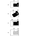
- FIG. 7 is a diagram illustrating an example of an input image to be generated.
- the input image 221 shown in FIG. 7A and the input image 222 shown in FIG. 7B are, for example, based on the condition setting information 143, the position of the camera 313 (the distance between the camera 313 and the imaging object 300), Generated by changing the posture.
- the input images 221 and 222 are generated by changing the position and rotation angle of the installation table 311 on which the imaging object 300 is installed.
- the input image 223 shown in FIG. 7C is an image in which the input image 221 is blurred.
- the input image 223 changes the focal length of the camera parameters from the state in which the input image 221 is captured in the focused state, or moves the installation base 311 to change the distance between the imaging object 300 and the camera 313. Generated by changing.
- the input image 224 shown in FIG. 7D is an image that is captured in a state where illumination is different from when the input image 221 is captured. Specifically, in the input image 224, since the amount of illumination light is too strong, the luminance of the surface of the imaging object 300 is larger than the original luminance.
- the input image 224 is generated, for example, by increasing the amount of light from the light source 316 or the light source 317 or bringing the light source 316 or the light source 317 closer to the imaging object 300 from the state in which the input image 221 is captured.
- FIG. 8 is a flowchart illustrating an example of a processing procedure of the learning data generation unit.
- the input unit 111 receives input of the facility setting information 142 in accordance with an operation of the operator, and stores the facility setting information 142 in the storage unit 115. Based on the stored facility setting information 142, the virtual facility construction unit 112 constructs a virtual facility in which the imaging target is installed in a three-dimensional space.
- the input unit 111 receives input of the condition setting information 143 in accordance with an operation by the operator, and stores the condition setting information 143 in the storage unit 115.
- the target image generation unit 114 receives the designation of the image processing type executed according to the generation target image processing program through the input unit 111.
- image processing types include straight edge detection, curved edge detection, circular edge detection, region detection, and template matching.
- the straight edge detection is a process for detecting a straight edge on the imaging target.
- the curved edge detection is a process for detecting a curved edge on the imaging object.
- the circular edge detection is a process for detecting a circular or elliptical edge on the imaging object.
- the area detection is a process for detecting an area of a specific part such as a part, a defective part, or a flaw area in the imaging target.
- Template matching is processing for detecting an area in which a template image is shown.
- the target image generation unit 114 causes the display device 104a to display a polygon model representing the imaging target as a collection of polygons based on the component data of the imaging target.
- Step S15 The target image generation unit 114 receives the selection operation for the displayed polygon model through the input unit 111, thereby receiving the selection of the recognition target portion on the imaging target. In this process, the target image generation unit 114 accepts selection of a recognition target portion by a selection method corresponding to the image processing type specified in step S13.
- the target image generation unit 114 selects a plurality of vertices on the edge to be recognized from the display image of the polygon model.
- the target image generation unit 114 selects a plurality of vertices at the outer edge of the recognition target object from the display image of the polygon model.
- the target image generation unit 114 extracts the coordinates of each selected vertex from the component data of the imaging target.
- the target image generation unit 114 may accept selection of a line segment of a polygon instead of a vertex from the polygon model. In this case, the coordinates of the vertices at both ends of the selected line segment are extracted.
- the target image generation unit 114 accepts a selection operation in units of parts, missing parts, and flaws composed of a plurality of polygons. For example, when a part included in the imaging target is selected, the target image generation unit 114 recognizes that the part has been selected when detecting a click operation on the display area of the part. The target image generation unit 114 extracts the coordinates of the vertices of each polygon included in the selected part, missing part, and scratch area from the part data of the imaging target.
- the example which selects a vertex etc. from the display image of a polygon model was shown here, for example, the data which shows the above-mentioned vertex, a part, a defective part, and an area of a flaw from part data showing an imaging subject, It may be selected directly by the operator from the list of component data.
- the input image generation unit 113 identifies an item described in the condition setting information 143 so as to change the setting value. When a plurality of items are specified, the input image generation unit 113 selects one set of combinations of setting values for each specified item. When only one item is specified, the input image generation unit 113 selects one set value for the item.
- Step S17 The input image generation unit 113 sets the state of the virtual facility and the imaging object installed therein to a state reflecting the setting value selected in Step S16. In this state, the input image generation unit 113 generates a captured image obtained by capturing an imaging target from the camera using a physical base simulation such as a photon mapping method or a ray tracing method. The generated image is output as an input image.
- a physical base simulation such as a photon mapping method or a ray tracing method.
- Step S18 The target image generation unit 114 converts the three-dimensional coordinates of each vertex specified in Step S15 into the two-dimensional coordinates when projected onto the input image generated in Step S17. This conversion is performed using at least a parameter indicating the positional relationship between the camera and the imaging object among the camera parameters set in the imaging in step S17.
- Step S19 The target image generation unit 114 performs processing according to the image processing type specified in step S13 on the projection image having the same size as the input image, based on the coordinates of each vertex after conversion. Thus, a target image corresponding to each input image is generated.
- the target image generating unit 114 calculates a straight line connecting the vertices on the projection image.
- the target image generation unit 114 calculates a curve connecting the vertices on the projection image.
- the target image generation unit 114 calculates a circle or an ellipse that connects the vertices on the projection image.
- the target image generation unit 114 calculates the shape of the outer shape of the recognition target object by connecting the vertices on the projection image.
- the target image generation unit 114 calculates the shape of the outer shape of the specific part to be recognized by connecting the vertices on the projection image, and then, for example, a rectangular area that includes the shape. The position of is calculated.
- the target image generation unit 114 generates, as a target image, an image in which the straight line, curve, circle, ellipse, outer shape, and rectangular area calculated as described above are drawn with luminance values different from those of other areas. To do.
- information indicating the position of the recognized region or the rectangular region in the projection image may be output as target data corresponding to the input image instead of the target image.
- Step S20 The target image generation unit 114 determines whether all setting values of items described in the condition setting information 143 are changed. If there is an unselected set value, the process of step S16 is executed. If all the corresponding setting values have been selected, the learning data 200 generation process ends.
- FIG. 9 is a flowchart illustrating an example of target image generation processing.
- FIG. 10 is a diagram illustrating an example of an image generated in the target image generation process.
- Step S15a This process corresponds to step S15 in FIG.
- the target image generation unit 114 receives a selection input of vertices constituting a linear edge to be recognized from the displayed polygon model.
- An image 410 in FIG. 10 is an example of an image on which a polygon model is displayed. The part indicated by the dotted line in the image 410 is the boundary of the polygon. In the example of the image 410, it is assumed that the vertices 411a to 411e constituting the edge portion 412 are selected by the operator.
- Step S18a corresponds to step S18 in FIG. [Step S18a]
- the target image generation unit 114 converts the three-dimensional coordinates of the vertices 411a to 411e into the two-dimensional coordinates when projected onto the input image, based on the camera parameters set when the corresponding input image is captured.
- the next steps S19a to S19c correspond to the process of step S19 in FIG. [Step S19a]
- the target image generation unit 114 calculates a straight line expression using a least square method or the like based on the converted two-dimensional coordinates of the vertices 411a to 411e.
- the target image generation unit 114 draws a straight line based on the calculated expression with a pixel value different from the background on a projection image having the same size as the input image and having a monochrome background.
- An image 420 in FIG. 10 has the same size as the input image, and a straight line 421 based on the calculated expression is drawn on the image 420 having a single color background.
- the field of view when the corresponding input image is captured does not include the vertex 411e.
- Step S ⁇ b> 19 c The target image generation unit 114 clips the pixels in the region outside the edge of the edge portion 412 to be recognized and the pixels in the region outside the window of the image 420 among the pixels of the straight line 421. To do. As a result, the image 420 in FIG. 10 is converted into an image 420a, and this image 420a is output as a target image.
- step S19c the process of clipping the linear region outside the end of the edge part is not essential, and whether or not to execute this process can be arbitrarily set by the operator.
- the learning data generation unit 110 According to the processing of the learning data generation unit 110 described above, it is possible to efficiently generate an input image obtained by capturing an image to be captured and its surrounding area under various imaging conditions, and shorten the generation processing time. Can do.
- the operator is made to select CAD data (three-dimensional coordinates) corresponding to the recognition target part.
- CAD data three-dimensional coordinates
- the recognition target part is accurately selected.
- a target image corresponding to the corresponding input image is generated using the result of projecting the recognition target part based on the selected CAD data onto the input image.
- the corresponding target image can be accurately generated regardless of how the captured object is captured in the input image. Therefore, learning for generating the image processing program 130 is performed using the target image generated in this manner, whereby the image processing program 130 that realizes highly accurate image processing can be generated.
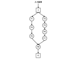
- FIG. 11 is a diagram illustrating an example of a tree structure constituting an individual.
- an individual is configured by combining one or more partial programs.
- an individual is defined by a tree structure.
- a plurality of partial programs that can be incorporated into individuals are prepared in the storage unit 122 in advance.
- each partial program is an image filter.
- the partial program is not limited to an image filter, and a program for performing other types of image processing may be used.
- “F1” to “F8” indicate image filters
- “I” indicates an input terminal
- “O” indicates an output terminal.
- straight edge detection, curved edge detection, circular edge detection, and region detection are performed. Each process can be realized.
- FIG. 12 is a diagram showing another example of a tree structure constituting an individual.
- FIG. 12 shows an example of a tree structure that realizes template matching.
- the individual shown in FIG. 12 includes two input terminals I1 and I2.
- An input image is input to the input terminal I1, and a template image is input to the input terminal I2.
- the region of the template image in the input image or the position information thereof is output.
- “F11” to “F17” are examples of image filters
- “M” is a partial program that executes a matching process between the output image of the image filter F17 and the template image from the input image I2.
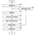
- FIG. 13 is a flowchart illustrating an example of a generation processing procedure of an image processing program using genetic programming.
- the program generation processing unit 121 generates a plurality of initial individuals to be included in the population. In each initial individual node, an image filter is randomly selected from a plurality of image filters prepared in advance and incorporated.
- the program generation processing unit 121 randomly selects a certain number of parent individuals from the population. Hereinafter, it is assumed that two parent individuals are selected as an example.
- the program generation processing unit 121 generates two or more constant child individuals by performing an evolution process on the two selected parent individuals. In the evolution process, crossover processing and mutation processing are performed on two parent individuals. Three or more child individuals may be generated by performing different crossover processing and mutation processing on the two parent individuals.
- Step S34 The program generation processing unit 121 calculates fitness for each of the parent individual selected in Step S32 and the child individual generated in Step S33. In this processing, image processing using each target individual is performed on each input image included in the learning data 200, and the fitness is calculated by comparing the image after execution with the corresponding target image. Is done. When there are a plurality of sets of input images and target images in the learning data 200, the average value of fitness obtained using the plurality of sets of input images and target images is calculated for each individual.
- the fitness of the initial individual included in the population may be calculated at the time when the population is generated in step S31. In this case, in step S34, only the fitness of the generated child individual is calculated.
- Step S35 The program generation processing unit 121 determines whether the fitness of any one of the generated child individuals and the original parent individual is greater than a predetermined threshold. If any fitness level is equal to or less than the threshold value, the process of step S36 is executed. When the fitness value of 1 or more is larger than the threshold value, the process of step S37 is executed.
- Step S36 The program generation processing unit 121 performs survival selection from the parent individual selected in Step S32 and the child individual generated in Step S33. For example, the individual with the maximum fitness value calculated is selected as the first surviving individual, and the second surviving individual is selected from the remaining individuals with a probability corresponding to the fitness value.
- the program generation processing unit 121 replaces two individuals selected as parent individuals in step S32 among the individuals included in the population with the first living individual and the second living individual. As a result, the generation of the population is updated.
- Step S37 The program generation processing unit 121 selects, as the best individual, the individual having the maximum fitness among the parent individual selected in Step S32 and the child individual generated in Step S33.
- the selected best individual becomes the optimized image processing program 130.
- the program generation processing unit 121 stores tree structure data indicating the selected best individual in a storage area such as the storage unit 122.
- FIG. 14 is a diagram showing a first example of image processing using an input image, a target image, and a generated image processing program.
- the input images 221 and 222 shown in FIG. 7 and the target images 221 a and 222 a corresponding thereto are generated by the learning data generation unit 110.
- the target images 221a and 222a straight lines 221b and 222b along the edge portion 231a of the imaging object 231 are drawn, respectively.
- the program generation unit 120 generates an image processing program 130a by performing learning using these input images 221, 222 and target images 221a, 222a.
- the image 301 is an example of a captured image in which the imaging target 231 is captured by a camera in actual equipment.
- an image 302 in which a straight line 302a along the edge portion 231a is accurately detected is output.
- FIG. 15 is a diagram illustrating a second example of the image processing using the input image and the target image and the generated image processing program.
- the edge portion 231a may not be accurately detected from the captured image. High nature. Therefore, when the captured image is likely to be blurred in the actual equipment, in addition to the input images 221 and 222 and the target images 221a and 222a in FIG. 14, for example, the input image 223 and the input image 223 in FIG. Re-learning of the image processing program is executed using the corresponding target image 223a. Thereby, the image processing program 130b is generated.
- the image 303 is an example of a captured image in which the imaging target 231 is captured by a camera in actual equipment.
- an image 304 in which the straight line 304a along the edge portion 231a is accurately detected is output.
- an image processing program that realizes image processing with higher robustness as more input images captured under different conditions and corresponding target images are used is generated. can do. Then, according to the program generation device 100, it is possible to efficiently generate many input images taken under different conditions and target images corresponding to these images in a short time. In addition, it is possible to reduce the operator's workload when generating these images.
- the processing functions of the devices can be realized by a computer.
- a program describing the processing contents of the functions that each device should have is provided, and the processing functions are realized on the computer by executing the program on the computer.
- the program describing the processing contents can be recorded on a computer-readable recording medium.
- the computer-readable recording medium include a magnetic storage device, an optical disk, a magneto-optical recording medium, and a semiconductor memory.
- the magnetic storage device include a hard disk device (HDD), a flexible disk (FD), and a magnetic tape.
- Optical discs include DVD (Digital Versatile Disc), DVD-RAM, CD-ROM (Compact Disc-Read Only Memory), CD-R (Recordable) / RW (ReWritable), and the like.
- Magneto-optical recording media include MO (Magneto-Optical disk).
- a portable recording medium such as a DVD or CD-ROM in which the program is recorded is sold. It is also possible to store the program in a storage device of a server computer and transfer the program from the server computer to another computer via a network.
- the computer that executes the program stores, for example, the program recorded on the portable recording medium or the program transferred from the server computer in its own storage device. Then, the computer reads the program from its own storage device and executes processing according to the program. The computer can also read the program directly from the portable recording medium and execute processing according to the program. In addition, each time a program is transferred from a server computer connected via a network, the computer can sequentially execute processing according to the received program.
Abstract
The present invention generates a highly accurate target image. An input-image generating unit (1a) generates a virtual captured image that would be obtained if an image of an object (3) were captured in a virtual space (2) and outputs the virtual captured image as an input image (11a) for generating an image processing program by way of learning. A target-image generating unit (1b) accepts selection of feature data corresponding to a feature region (3a) of the object (3) from shape data (1c) representing the three-dimensional shape of the object (3). The target-image generating unit (1b) calculates a position where the feature region (3a) is to be projected in the input image (11a) on the basis of the feature data and generates a target image (12a) corresponding to the input image (11a) on the basis of the calculated projected position.
Description
本発明は、画像処理装置、画像処理方法および画像処理プログラムに関する。
The present invention relates to an image processing apparatus, an image processing method, and an image processing program.
画像処理アルゴリズムは、専門のスキルを持つ者が知識と経験を基に試行錯誤的に生成するものであった。ところが近年では、遺伝的アルゴリズムや遺伝的プログラミング、SA(Simulated Annealing)などの最適化手法を用いることにより、目的の機能を有する画像処理プログラムを自動的に生成する技術が開発されている。この技術では、入力画像とその処理結果(例えば、目標画像)とを用いた学習が行われる。例えば、遺伝的プログラミングを用いた例としては、入力画像とその処理結果とを用いて、画像処理のための部分プログラム(例えば、画像フィルタのプログラム)を組み合わせて生成される画像処理プログラムが最適化される。
The image processing algorithm was generated by a person with specialized skills on a trial and error basis based on knowledge and experience. However, in recent years, a technique for automatically generating an image processing program having a target function by using an optimization method such as a genetic algorithm, genetic programming, or SA (Simulated Annealing) has been developed. In this technique, learning using an input image and a processing result (for example, a target image) is performed. For example, as an example using genetic programming, an image processing program generated by combining a partial program (for example, an image filter program) for image processing using an input image and its processing result is optimized. Is done.
また、対象物体の姿勢を推定する識別器の学習を行うためにこの識別器に与える学習用画像を生成する次のような情報処理装置が提案されている。この情報処理装置は、対象物体の形状モデルに少なくとも1つの視点を設定し、この視点から形状モデルを観察したときに、視点と形状モデルとが所定の条件を満たした場合に、この視点から形状モデルを見た形状モデルの画像を学習用画像とする。
Also, the following information processing apparatus has been proposed that generates a learning image to be given to a discriminator in order to learn a discriminator that estimates the posture of the target object. This information processing apparatus sets at least one viewpoint to the shape model of the target object, and when the shape model is observed from this viewpoint, the shape is determined from this viewpoint when the viewpoint and the shape model satisfy a predetermined condition. An image of a shape model viewed from the model is used as a learning image.
ところで、画像処理プログラムの自動生成に用いる目標画像は、例えば、対応する入力画像に対して、オペレータの操作によりレタッチなどの画像処理が施されることによって生成される。しかし、このような方法では、オペレータのスキルや性格によっては正確性の高い目標画像を生成することができず、その結果、生成された画像処理プログラムを用いた画像処理の精度が低下してしまうことがある。例えば、入力画像は、画像認識の対象とする特徴部位を含む対象物を、撮像パラメータや周囲の環境の条件を様々に変化させることで得られる。このため、入力画像によって特徴部位の写り方は様々であり、オペレータによって特徴部位の位置を正確に特定できないことも多い。その結果、正確性の高い目標画像を生成できなくなってしまう。
By the way, a target image used for automatic generation of an image processing program is generated, for example, by subjecting a corresponding input image to image processing such as retouching by an operator's operation. However, with such a method, a highly accurate target image cannot be generated depending on the skill and personality of the operator, and as a result, the accuracy of image processing using the generated image processing program decreases. Sometimes. For example, an input image can be obtained by changing an imaging parameter and surrounding environmental conditions variously for an object including a characteristic part that is an object of image recognition. For this reason, there are various ways of capturing the characteristic part depending on the input image, and the position of the characteristic part cannot often be accurately specified by the operator. As a result, a highly accurate target image cannot be generated.
1つの側面では、本発明は、正確性の高い目標画像を生成可能な画像処理装置、画像処理方法および画像処理プログラムを提供することを目的とする。
In one aspect, an object of the present invention is to provide an image processing apparatus, an image processing method, and an image processing program capable of generating a highly accurate target image.
1つの案では、入力画像生成部と、目標画像生成部とを有する画像処理装置が提供される。入力画像生成部は、仮想空間において対象物を撮像したときの仮想撮像画像を生成し、仮想撮像画像を、画像処理プログラムを学習により生成するための入力画像として出力する。目標画像生成部は、対象物の3次元形状を示す形状データの中から、対象物における特徴部位に対応する特徴データの選択を受け付け、入力画像における特徴部位の投影位置を特徴データに基づいて算出し、入力画像に対応する目標画像を投影位置に基づいて生成する。
In one proposal, an image processing apparatus having an input image generation unit and a target image generation unit is provided. The input image generation unit generates a virtual captured image when an object is imaged in the virtual space, and outputs the virtual captured image as an input image for generating an image processing program by learning. The target image generation unit receives selection of feature data corresponding to a feature part in the target object from shape data indicating the three-dimensional shape of the target object, and calculates a projection position of the feature part in the input image based on the feature data Then, a target image corresponding to the input image is generated based on the projection position.
また、1つの案では、上記の画像処理装置と同様の処理がコンピュータによって実行される画像処理方法が提供される。
さらに、1つの案では、上記の画像処理装置と同様の処理をコンピュータに実行させる画像処理プログラムが提供される。 In one proposal, an image processing method is provided in which processing similar to that of the above-described image processing apparatus is executed by a computer.
Furthermore, in one proposal, an image processing program that causes a computer to execute the same processing as that of the above-described image processing apparatus is provided.
1つの側面では、正確性の高い目標画像を生成できる。
本発明の上記および他の目的、特徴および利点は本発明の例として好ましい実施の形態を表す添付の図面と関連した以下の説明により明らかになるであろう。 In one aspect, a highly accurate target image can be generated.
These and other objects, features and advantages of the present invention will become apparent from the following description taken in conjunction with the accompanying drawings which illustrate preferred embodiments by way of example of the present invention.
以下、本発明の実施の形態について図面を参照して説明する。
〔第1の実施の形態〕
図1は、第1の実施の形態に係る画像処理装置の構成例および処理例を示す図である。図1に示す画像処理装置1は、画像処理プログラムを学習により生成するための入力画像および目標画像を生成する装置である。画像処理装置1は、入力画像生成部1aと目標画像生成部1bとを有する。入力画像生成部1aおよび目標画像生成部1bの処理は、例えば、画像処理装置1が備えるプロセッサが所定のプログラムを実行することで実現される。 Hereinafter, embodiments of the present invention will be described with reference to the drawings.
[First Embodiment]
FIG. 1 is a diagram illustrating a configuration example and a processing example of the image processing apparatus according to the first embodiment. Animage processing apparatus 1 shown in FIG. 1 is an apparatus that generates an input image and a target image for generating an image processing program by learning. The image processing apparatus 1 includes an input image generation unit 1a and a target image generation unit 1b. The processing of the input image generation unit 1a and the target image generation unit 1b is realized by, for example, a processor included in the image processing device 1 executing a predetermined program.
〔第1の実施の形態〕
図1は、第1の実施の形態に係る画像処理装置の構成例および処理例を示す図である。図1に示す画像処理装置1は、画像処理プログラムを学習により生成するための入力画像および目標画像を生成する装置である。画像処理装置1は、入力画像生成部1aと目標画像生成部1bとを有する。入力画像生成部1aおよび目標画像生成部1bの処理は、例えば、画像処理装置1が備えるプロセッサが所定のプログラムを実行することで実現される。 Hereinafter, embodiments of the present invention will be described with reference to the drawings.
[First Embodiment]
FIG. 1 is a diagram illustrating a configuration example and a processing example of the image processing apparatus according to the first embodiment. An
入力画像生成部1aは、3次元の仮想空間2において対象物3を撮像したときの仮想撮像画像を、入力画像として出力する。図1の例では、仮想空間2上に設置されたカメラ4aから対象物3を仮想的に撮像することで、入力画像11aが生成される。また、カメラ4aとは異なる位置に設置されたカメラ4bから対象物3を仮想的に撮像することで、入力画像11bが生成される。入力画像11aと入力画像11bとの間では、対象物3が異なる方向を向いた状態で写っている。なお、入力画像は、少なくとも1枚生成されればよい。
The input image generation unit 1a outputs a virtual captured image when the object 3 is captured in the three-dimensional virtual space 2 as an input image. In the example of FIG. 1, the input image 11 a is generated by virtually imaging the object 3 from the camera 4 a installed in the virtual space 2. Moreover, the input image 11b is produced | generated by imaging the target object 3 virtually from the camera 4b installed in the position different from the camera 4a. Between the input image 11a and the input image 11b, the object 3 is shown in a state of facing different directions. Note that at least one input image may be generated.
目標画像生成部1bは、対象物3の3次元形状を示す形状データ1cを参照可能になっている。形状データ1cは、例えば、仮想空間2における対象物3の複数の部位の3次元座標を含む。なお、形状データ1cは、例えば、画像処理装置1が有する記憶部1dに記憶されている。記憶部1dは、画像処理装置1が備える記憶装置の記憶領域として実装される。
The target image generation unit 1b can refer to the shape data 1c indicating the three-dimensional shape of the object 3. The shape data 1c includes, for example, three-dimensional coordinates of a plurality of parts of the object 3 in the virtual space 2. The shape data 1c is stored, for example, in the storage unit 1d included in the image processing apparatus 1. The storage unit 1d is implemented as a storage area of a storage device included in the image processing apparatus 1.
目標画像生成部1bは、形状データ1cの中から、対象物3における特徴部位3aに対応する特徴データの選択を受け付ける。特徴部位3aは、例えば、生成される画像処理プログラムによって画像の中から抽出される部位である。特徴データの選択は、例えば、次のようにして行われる。
The target image generation unit 1b accepts selection of feature data corresponding to the feature part 3a in the object 3 from the shape data 1c. The characteristic part 3a is a part extracted from the image by the generated image processing program, for example. The feature data is selected as follows, for example.
目標画像生成部1bは、対象物3の形状を表すポリゴンの頂点のうち、特徴部位3aに対応する頂点のデータの選択を受ける。より具体的な例としては、目標画像生成部1bは、対象物3の形状を複数のポリゴンの組み合わせとして表すポリゴンモデルを図示しない表示装置に表示させ、ポリゴンモデル上の頂点の中から、特徴部位3aに対応する頂点の選択を受け付ける。目標画像生成部1bは、特徴データとして、選択された頂点についてのデータを形状データ1cから抽出する。
The target image generation unit 1b receives selection of vertex data corresponding to the characteristic part 3a among polygon vertices representing the shape of the object 3. As a more specific example, the target image generation unit 1b displays a polygon model representing the shape of the object 3 as a combination of a plurality of polygons on a display device (not shown), and from among the vertices on the polygon model, The selection of the vertex corresponding to 3a is accepted. The target image generation unit 1b extracts data about the selected vertex from the shape data 1c as feature data.
図1の例では、特徴部位3aは対象物3上の直線状のエッジである。そして、対象物3のポリゴンモデルからエッジ上に存在する複数の頂点5a~5cが選択される。この場合、特徴部位3aに対応する特徴データは、例えば、頂点5a~5cの3次元座標群として選択される。
In the example of FIG. 1, the characteristic part 3 a is a straight edge on the object 3. Then, a plurality of vertices 5a to 5c existing on the edge are selected from the polygon model of the object 3. In this case, the feature data corresponding to the feature part 3a is selected as a three-dimensional coordinate group of the vertices 5a to 5c, for example.
あるいは、特徴部位3aとして選択可能な部位にそれぞれ対応する形状データのリストの中から、所望の形状データが特徴データとして選択されてもよい。選択可能な部位としては、例えば、頂点、線分、ポリゴンなどがある。
Alternatively, desired shape data may be selected as feature data from a list of shape data respectively corresponding to portions that can be selected as the feature portion 3a. Examples of selectable parts include vertices, line segments, and polygons.
目標画像生成部1bは、生成された入力画像11aにおける特徴部位3aの投影位置を特徴データに基づいて算出する。目標画像生成部1bは、入力画像11aに対応する目標画像12aを、算出された投影位置に基づいて生成する。また、目標画像生成部1bは同様に、生成された入力画像11bにおける特徴部位3aの投影位置を特徴データに基づいて算出する。目標画像生成部1bは、入力画像11bに対応する目標画像12bを、算出された投影位置に基づいて生成する。
The target image generation unit 1b calculates the projection position of the feature part 3a in the generated input image 11a based on the feature data. The target image generation unit 1b generates a target image 12a corresponding to the input image 11a based on the calculated projection position. Similarly, the target image generation unit 1b calculates the projection position of the feature part 3a in the generated input image 11b based on the feature data. The target image generation unit 1b generates a target image 12b corresponding to the input image 11b based on the calculated projection position.
例えば、目標画像生成部1bは、頂点5a~5cの各3次元座標を、頂点5a~5cを入力画像11aに投影したときの投影座標に変換し、投影座標に基づいて特徴部位3aの領域を描画した目標画像12aを生成する。図1の例では、入力画像11aと同じサイズの目標画像12aにおける投影座標が示す位置に、特徴領域3aが描画されている。また、目標画像生成部1bは同様に、頂点5a~5cの各3次元座標を、頂点5a~5cを入力画像11bに投影したときの投影座標に変換し、投影座標に基づいて特徴部位3aの領域を描画した目標画像12bを生成する。図1の例では、入力画像11bと同じサイズの目標画像12bにおける投影座標が示す位置に、特徴部位3aが描画されている。
For example, the target image generating unit 1b converts the three-dimensional coordinates of the vertices 5a to 5c into projection coordinates when the vertices 5a to 5c are projected onto the input image 11a, and the region of the characteristic part 3a is converted based on the projected coordinates. The drawn target image 12a is generated. In the example of FIG. 1, the feature region 3a is drawn at the position indicated by the projection coordinates in the target image 12a having the same size as the input image 11a. Similarly, the target image generation unit 1b converts the three-dimensional coordinates of the vertices 5a to 5c into projection coordinates when the vertices 5a to 5c are projected onto the input image 11b, and the feature part 3a is converted based on the projection coordinates. A target image 12b in which a region is drawn is generated. In the example of FIG. 1, the characteristic part 3a is drawn at the position indicated by the projection coordinates in the target image 12b having the same size as the input image 11b.
ここで、例えば入力画像11aに対応する目標画像を生成する方法としては、次のような方法が考えられる。例えば、オペレータの操作により入力画像11aから特徴部位3aを抽出し、レタッチなどの画像処理を入力画像11aに施すことで、対応する目標画像を生成する方法が考えられる。しかし、入力画像11aは様々な撮像条件の下で撮像され得るので、入力画像11aに対象物3や特徴部位3aが明瞭に写っていない場合がある。この場合、オペレータは特徴部位3aの位置を正確に判断することができない。このため、生成される目標画像の品質が低下し、その結果、生成される画像処理プログラムに基づく画像処理精度が低下してしまう。
Here, for example, the following method can be considered as a method of generating the target image corresponding to the input image 11a. For example, a method of generating a corresponding target image by extracting the characteristic part 3a from the input image 11a by an operator's operation and performing image processing such as retouching on the input image 11a can be considered. However, since the input image 11a can be imaged under various imaging conditions, the object 3 and the characteristic part 3a may not be clearly shown in the input image 11a. In this case, the operator cannot accurately determine the position of the characteristic part 3a. For this reason, the quality of the generated target image is lowered, and as a result, the image processing accuracy based on the generated image processing program is lowered.
これに対して、第1の実施の形態に係る画像処理装置1では、対象物3の3次元形状を表す形状データ1cの中から、対象物3における特徴部位3aに対応する特徴データが選択される。そして、入力画像11aにおける特徴部位3aの投影位置が、選択された特徴データに基づいて算出され、算出された投影位置に基づいて、入力画像11aに対応する目標画像12aが生成される。これにより、入力画像11aにおける特徴部位3aの写り方に関係なく、正確性の高い目標画像12aを生成することができる。
On the other hand, in the image processing apparatus 1 according to the first embodiment, feature data corresponding to the feature part 3a in the target object 3 is selected from the shape data 1c representing the three-dimensional shape of the target object 3. The Then, the projection position of the feature part 3a in the input image 11a is calculated based on the selected feature data, and the target image 12a corresponding to the input image 11a is generated based on the calculated projection position. Thereby, the target image 12a with high accuracy can be generated regardless of how the feature part 3a is captured in the input image 11a.
〔第2の実施の形態〕
次に、第2の実施の形態に係るプログラム生成装置について説明する。第2の実施の形態に係るプログラム生成装置は、図1に示した画像処理装置1と同様の入力画像および目標画像の生成機能に加えて、生成された入力画像および目標画像を用いて画像処理プログラムを自動生成する機能を備える。 [Second Embodiment]
Next, a program generation device according to the second embodiment will be described. The program generation apparatus according to the second embodiment performs image processing using the generated input image and target image in addition to the same input image and target image generation function as theimage processing apparatus 1 shown in FIG. A function to automatically generate a program is provided.
次に、第2の実施の形態に係るプログラム生成装置について説明する。第2の実施の形態に係るプログラム生成装置は、図1に示した画像処理装置1と同様の入力画像および目標画像の生成機能に加えて、生成された入力画像および目標画像を用いて画像処理プログラムを自動生成する機能を備える。 [Second Embodiment]
Next, a program generation device according to the second embodiment will be described. The program generation apparatus according to the second embodiment performs image processing using the generated input image and target image in addition to the same input image and target image generation function as the
図2は、第2の実施の形態に係るプログラム生成装置のハードウェア構成例を示す図である。第2の実施の形態に係るプログラム生成装置100は、例えば、図2に示すようなコンピュータとして実現される。
FIG. 2 is a diagram illustrating a hardware configuration example of the program generation device according to the second embodiment. The program generation device 100 according to the second embodiment is realized as a computer as shown in FIG. 2, for example.
プログラム生成装置100は、プロセッサ101によって装置全体が制御されている。プロセッサ101は、マルチプロセッサであってもよい。プロセッサ101は、例えばCPU(Central Processing Unit)、MPU(Micro Processing Unit)、DSP(Digital Signal Processor)、ASIC(Application Specific Integrated Circuit)、またはPLD(Programmable Logic Device)である。また、プロセッサ101は、CPU、MPU、DSP、ASIC、PLDのうちの2以上の要素の組み合わせであってもよい。
The entire program generation apparatus 100 is controlled by the processor 101. The processor 101 may be a multiprocessor. The processor 101 is, for example, a CPU (Central Processing Unit), an MPU (Micro Processing Unit), a DSP (Digital Signal Processor), an ASIC (Application Specific Integrated Circuit), or a PLD (Programmable Logic Device). The processor 101 may be a combination of two or more elements among CPU, MPU, DSP, ASIC, and PLD.
プロセッサ101には、バス108を介して、RAM(Random Access Memory)102と複数の周辺機器が接続されている。
RAM102は、プログラム生成装置100の主記憶装置として使用される。RAM102には、プロセッサ101に実行させるOS(Operating System)プログラムやアプリケーションプログラムの少なくとも一部が一時的に格納される。また、RAM102には、プロセッサ101による処理に必要な各種データが格納される。 A RAM (Random Access Memory) 102 and a plurality of peripheral devices are connected to theprocessor 101 via a bus 108.
TheRAM 102 is used as a main storage device of the program generation device 100. The RAM 102 temporarily stores at least part of an OS (Operating System) program and application programs to be executed by the processor 101. The RAM 102 stores various data necessary for processing by the processor 101.
RAM102は、プログラム生成装置100の主記憶装置として使用される。RAM102には、プロセッサ101に実行させるOS(Operating System)プログラムやアプリケーションプログラムの少なくとも一部が一時的に格納される。また、RAM102には、プロセッサ101による処理に必要な各種データが格納される。 A RAM (Random Access Memory) 102 and a plurality of peripheral devices are connected to the
The
バス108に接続されている周辺機器としては、HDD(Hard Disk Drive)103、グラフィック処理装置104、入力インタフェース105、読み取り装置106および通信インタフェース107がある。
Peripheral devices connected to the bus 108 include an HDD (Hard Disk Drive) 103, a graphic processing device 104, an input interface 105, a reading device 106, and a communication interface 107.
HDD103は、プログラム生成装置100の補助記憶装置として使用される。HDD103には、OSプログラム、アプリケーションプログラム、および各種データが格納される。なお、補助記憶装置としては、SSD(Solid State Drive)などの他の種類の不揮発性記憶装置を使用することもできる。
The HDD 103 is used as an auxiliary storage device of the program generation device 100. The HDD 103 stores an OS program, application programs, and various data. As the auxiliary storage device, other types of nonvolatile storage devices such as SSD (SolidSoState Drive) can be used.
グラフィック処理装置104には、表示装置104aが接続されている。グラフィック処理装置104は、プロセッサ101からの命令にしたがって、画像を表示装置104aの画面に表示させる。表示装置104aとしては、液晶ディスプレイや有機EL(ElectroLuminescence)ディスプレイなどがある。
The graphic processing device 104 is connected to a display device 104a. The graphic processing device 104 displays an image on the screen of the display device 104a in accordance with an instruction from the processor 101. Examples of the display device 104a include a liquid crystal display and an organic EL (ElectroLuminescence) display.
入力インタフェース105には、入力装置105aが接続されている。入力インタフェース105は、入力装置105aから出力される信号をプロセッサ101に送信する。入力装置105aとしては、キーボードやポインティングデバイスなどがある。ポインティングデバイスとしては、マウス、タッチパネル、タブレット、タッチパッド、トラックボールなどがある。
The input device 105 a is connected to the input interface 105. The input interface 105 transmits a signal output from the input device 105a to the processor 101. Examples of the input device 105a include a keyboard and a pointing device. Examples of pointing devices include a mouse, a touch panel, a tablet, a touch pad, and a trackball.
読み取り装置106には、可搬型記録媒体106aが脱着される。読み取り装置106は、可搬型記録媒体106aに記録されたデータを読み取ってプロセッサ101に送信する。可搬型記録媒体106aとしては、光ディスク、光磁気ディスク、半導体メモリなどがある。
The portable recording medium 106a is detached from the reading device 106. The reading device 106 reads the data recorded on the portable recording medium 106 a and transmits it to the processor 101. Examples of the portable recording medium 106a include an optical disk, a magneto-optical disk, and a semiconductor memory.
通信インタフェース107は、ネットワーク107aを介して他の装置との間でデータの送受信を行う。
以上のようなハードウェア構成によって、プログラム生成装置100の処理機能を実現することができる。 Thecommunication interface 107 transmits / receives data to / from other devices via the network 107a.
With the hardware configuration described above, the processing functions of theprogram generation device 100 can be realized.
以上のようなハードウェア構成によって、プログラム生成装置100の処理機能を実現することができる。 The
With the hardware configuration described above, the processing functions of the
図3は、プログラム生成装置の処理機能の例を示すブロック図である。プログラム生成装置100は、学習データ生成部110およびプログラム生成部120を有する。学習データ生成部110およびプログラム生成部120の処理は、例えば、それぞれ個別のアプリケーションプログラムがプロセッサ101によって実行されることで実現される。あるいは、学習データ生成部110およびプログラム生成部120の処理は、一体のアプリケーションプログラムを用いて実現されてもよい。
FIG. 3 is a block diagram illustrating an example of processing functions of the program generation device. The program generation device 100 includes a learning data generation unit 110 and a program generation unit 120. The processing of the learning data generation unit 110 and the program generation unit 120 is realized by, for example, each application program being executed by the processor 101. Alternatively, the processes of the learning data generation unit 110 and the program generation unit 120 may be realized using an integrated application program.
学習データ生成部110は、プログラム生成部120による画像処理プログラム130の生成処理において利用される学習データ200を生成する。学習データ200には、入力画像と、生成される画像処理プログラム130を用いて入力画像を処理した際の処理結果の目標を示す目標データとが含まれる。本実施の形態では例として、目標データは目標画像として生成されるものとするが、位置座標などの数値として生成されてもよい。
The learning data generation unit 110 generates learning data 200 used in the generation processing of the image processing program 130 by the program generation unit 120. The learning data 200 includes an input image and target data indicating a target of a processing result when the input image is processed using the generated image processing program 130. In the present embodiment, as an example, the target data is generated as a target image, but may be generated as a numerical value such as a position coordinate.
プログラム生成部120は、生成された1組以上の学習データ200を用いた学習により、画像処理プログラム130を自動的に生成する。例えば、プログラム生成部120は、遺伝的プログラミングを用いて画像処理プログラム130を生成する。
The program generation unit 120 automatically generates the image processing program 130 by learning using the generated one or more sets of learning data 200. For example, the program generation unit 120 generates the image processing program 130 using genetic programming.
ここで、図4は、生成される画像処理プログラムによって実現される画像処理の例を示す図である。画像処理プログラム130によって実現される画像処理としては、例えば、エッジ検出、領域検出、テンプレートマッチングなどがある。図4では、エッジ検出処理の一例を示している。
Here, FIG. 4 is a diagram illustrating an example of image processing realized by the generated image processing program. Examples of image processing realized by the image processing program 130 include edge detection, area detection, template matching, and the like. FIG. 4 shows an example of edge detection processing.
図4において、入力画像201は、生成された画像処理プログラム130を用いて処理される撮像画像であり、出力画像202は、その処理結果として出力される画像である。図4の例では、入力画像201に写っている撮像対象物201aにおける特定のエッジ201bを示す直線202aが検出される。なお、直線202aのように画像全体を横切るような直線ではなく、画像201-2のようにエッジ201bの部分だけを示す線分201cが検出されてもよい。
In FIG. 4, an input image 201 is a captured image processed using the generated image processing program 130, and an output image 202 is an image output as the processing result. In the example of FIG. 4, a straight line 202a indicating a specific edge 201b in the imaging target 201a shown in the input image 201 is detected. Instead of a straight line that traverses the entire image like the straight line 202a, a line segment 201c that indicates only the edge 201b may be detected like the image 201-2.
また、エッジ検出としては、直線形状だけでなく、円形状のエッジが検出されてもよい。また、領域検出としては、例えば、図4中の撮像対象物201aの外形が包含されるような矩形領域を検出する処理や、撮像対象物201aに存在する欠損領域や傷のある領域を検出する処理などがある。また、テンプレートマッチングとしては、撮像対象物201aの画像をテンプレートとして用い、撮像画像における撮像対象物201aの基準点の位置座標を検出する処理などがある。
In addition, as edge detection, not only a linear shape but also a circular edge may be detected. In addition, as the area detection, for example, a process of detecting a rectangular area in which the outer shape of the imaging target 201a in FIG. 4 is included, or a defective area or a scratched area existing in the imaging target 201a is detected. There is processing. The template matching includes a process of using the image of the imaging target 201a as a template and detecting the position coordinates of the reference point of the imaging target 201a in the captured image.
画像処理プログラム130の用途としては、例えば、FA(Factory Automation)分野において、製品や部品を撮像した画像に画像処理を施して所望の効果を得るという用途が考えられる。例えば、製品の外観を撮像した画像に画像処理を施して、位置合わせを行う箇所を抽出する、欠陥が生じた箇所を抽出するといった用途が考えられる。
As an application of the image processing program 130, for example, in the FA (Factory Automation) field, an application in which an image obtained by capturing a product or a part is subjected to image processing to obtain a desired effect can be considered. For example, it is conceivable that the image of the appearance of the product is subjected to image processing to extract a position where alignment is performed, or a position where a defect has occurred is extracted.
このような用途では、撮像対象物となる製品や部品が搭載される設備の設置環境の変化、あるいは、製品や部品の変更、改良などに応じて、画像処理アルゴリズムを最適化する必要がある。この最適化のためには、設備の環境変化や製品、部品の変化に応じた適切な学習データが必要となる。
In such applications, it is necessary to optimize the image processing algorithm in accordance with changes in the installation environment of the equipment on which the product or part to be imaged is mounted, or changes or improvements in the product or part. For this optimization, appropriate learning data according to changes in the environment of equipment and changes in products and parts is required.
一般的に、学習データに含まれる入力画像は、実際の設備または動作確認用の実験用設備を実際に設置し、そこに撮像対象物の実物またはその試作品を搭載した状態で、撮像対象物を撮像することによって用意される。しかし、実際に起こりうる様々な環境変化を実機を用いてすべて再現することは困難であるという問題がある。また、実機を用いて再現するための作業の手間が大きく、作業時間が長くなるという問題もある。
In general, the input image included in the learning data is the actual object or experimental equipment for operation check, and the actual object or prototype of the object is mounted on it. It is prepared by imaging. However, there is a problem that it is difficult to reproduce all the various environmental changes that can actually occur using an actual machine. In addition, there is a problem in that the time and effort required for reproduction using a real machine is large and the work time is long.
また、例えば、製品の生産設備において画像処理プログラム130を用いて製品の位置合わせや外観検査を行うケースでは、生産設備は、開発設計、立ち上げというプロセスを経た後に稼働される。通常は、生産設備の立ち上げの直前のタイミングで、画像処理プログラム130の検証が行われ、画像処理精度に問題がある場合には新たな入力画像および目標画像が追加されて再学習が行われ、画像処理プログラム130が最適化される。この再学習のための入力画像に長い時間がかかると、その分だけ生産設備の稼働が遅延してしまうという問題がある。
Also, for example, in the case where product image alignment 130 and appearance inspection are performed using the image processing program 130 in the production facility of the product, the production facility is operated after undergoing processes of development design and startup. Normally, the image processing program 130 is verified immediately before the start-up of the production facility. If there is a problem with image processing accuracy, a new input image and target image are added and relearning is performed. The image processing program 130 is optimized. If an input image for this relearning takes a long time, there is a problem that the operation of the production facility is delayed correspondingly.
また、学習データに含まれる目標画像は、例えば、オペレータが、上記のように生成された入力画像の表示画面を見ながら、マウスなどの入力操作によって認識対象のエッジや領域の輪郭を指定していくことで生成される。あるいは、目標画像は、オペレータの操作によって、入力画像に様々な画像処理が施されることで生成される。図4の例では、入力画像201に対してエッジを検出する画像処理が施されることで、撮像対象物201aの輪郭を示すエッジが抽出された画像201-1が得られている。そして、オペレータの操作により、画像201-1から必要なエッジ201b以外の部分が消去されることで、線分201cのみを含む画像201-2が得られている。
The target image included in the learning data is, for example, when the operator specifies the edge of the recognition target or the outline of the region by an input operation using a mouse or the like while viewing the display screen of the input image generated as described above. It is generated by going. Alternatively, the target image is generated by performing various image processing on the input image by the operation of the operator. In the example of FIG. 4, an image 201-1 in which an edge indicating the contour of the imaging target 201a is extracted is obtained by performing image processing for detecting an edge on the input image 201. Then, an image 201-2 including only the line segment 201c is obtained by erasing a portion other than the necessary edge 201b from the image 201-1 by the operation of the operator.
しかし、このような方法では、オペレータの作業の手間が大きく、作業時間が長くなるという問題がある。また、オペレータのスキルや性格などにより目標画像の正確さにバラツキが発生し、その結果、生成された画像処理プログラム130による画像処理の精度が低下するという問題もある。さらに、次の図5に示す例のように、オペレータの操作ではそもそも正しい目標画像を生成するのが困難であるというケースもある。
However, in such a method, there is a problem that the work of the operator is large and the work time becomes long. In addition, there is a problem that the accuracy of the target image varies depending on the skill and personality of the operator, and as a result, the accuracy of image processing by the generated image processing program 130 is lowered. Furthermore, as in the example shown in FIG. 5, there are cases where it is difficult to generate a correct target image in the first place by an operator's operation.
図5は、入力画像の例を示す図である。図5(A)に示す入力画像211、および図5(B)に示す入力画像212では、どちらも撮像対象物213が撮像されている。ただし、入力画像211はボケのない画像であるのに対して、入力画像212はボケが大きい画像となっている。オペレータは、このような入力画像212からは、撮像対象物213における特定のエッジ213aがどこに存在するのかを正確に判断することができない。このため、入力画像212からオペレータの操作によって正しい目標画像を生成することは困難である。
FIG. 5 is a diagram showing an example of the input image. In both the input image 211 shown in FIG. 5A and the input image 212 shown in FIG. 5B, the imaging object 213 is imaged. However, the input image 211 is an image without blur, whereas the input image 212 is an image with large blur. The operator cannot accurately determine where the specific edge 213a in the imaging target 213 exists from such an input image 212. For this reason, it is difficult to generate a correct target image from the input image 212 by an operator's operation.
そこで、本実施の形態において、学習データ生成部110は、CAD(Computer Aided Design)データを用いて、撮像対象物が搭載される設備を仮想的に再現した仮想設備を構築する。また、学習データ生成部110は、仮想設備における光源の状態や可動部品の位置、撮像対象物の位置や姿勢、カメラパラメータなど、入力画像を仮想的に撮像する際の条件をどのように変化させるかを示す情報の入力を受ける。そして、学習データ生成部110は、仮想設備を入力された条件に合致する状態に設定するとともに、仮想設備上に撮像対象物を入力された条件に合致する状態で配置し、撮像対象物を仮想的なカメラによって撮像することで、入力画像を生成する。
Therefore, in the present embodiment, the learning data generation unit 110 uses the CAD (Computer Aided Design) data to construct a virtual facility that virtually reproduces the facility on which the imaging target is mounted. In addition, the learning data generation unit 110 changes the conditions when the input image is virtually captured, such as the state of the light source in the virtual facility, the position of the movable part, the position and orientation of the imaging target, and camera parameters. Receives information that indicates Then, the learning data generation unit 110 sets the virtual facility to a state that matches the input condition, and arranges the imaging target object on the virtual facility in a state that matches the input condition, An input image is generated by taking an image with a typical camera.
これにより、実際の設備を使用することなく、設備の様々な状態を仮想的に再現し、それらの状態で撮像対象物を撮像した入力画像を得ることができる。したがって、入力画像を生成する作業効率を向上させることができ、その作業時間を短縮できる。
This makes it possible to virtually reproduce various states of the equipment without using the actual equipment, and to obtain an input image obtained by imaging the imaging object in those states. Therefore, the work efficiency for generating the input image can be improved, and the work time can be shortened.
また、学習データ生成部110は、上記条件に基づく仮想設備および撮像対象物の状態設定とは別に、撮像対象物を示すCADデータの中から、撮像対象物における認識対象部位に対応するデータを指定するための入力を受け付ける。具体的には、学習データ生成部110は、撮像対象物のポリゴンモデルを表示装置104aに表示させ、表示されたポリゴンモデル上の頂点の中から、認識対象部位に対応する頂点をオペレータに選択させる。これにより、選択された頂点の座標データが特定される。
Further, the learning data generation unit 110 designates data corresponding to the recognition target part in the imaging target from the CAD data indicating the imaging target, separately from the virtual equipment and the state setting of the imaging target based on the above conditions. Accept input to Specifically, the learning data generation unit 110 displays the polygon model of the imaging target on the display device 104a, and causes the operator to select a vertex corresponding to the recognition target part from the vertices on the displayed polygon model. . Thereby, the coordinate data of the selected vertex is specified.
学習データ生成部110は、特定された座標データに基づいて、選択された各頂点の入力画像での投影位置を算出し、この算出結果に基づいて、入力画像と同じサイズの画像上に各頂点が投影された投影画像を生成する。学習データ生成部110は、投影画像上の頂点の位置から直線や曲線、あるいは線で囲まれた領域を特定し、特定された線や領域を描画することで目標画像を生成する。
The learning data generation unit 110 calculates a projection position in the input image of each selected vertex based on the specified coordinate data, and based on the calculation result, each vertex is displayed on an image having the same size as the input image. Is projected. The learning data generation unit 110 specifies a straight line, a curve, or an area surrounded by lines from the position of the vertex on the projection image, and generates the target image by drawing the specified line or area.
このような方法によれば、生成された入力画像から認識対象部位をオペレータに特定させるのではなく、認識対象部位の少なくとも一部を示すCADデータが選択される。そして、選択されたCADデータを基に入力画像の生成時と同様の投影変換が再度行われることで、目標画像が生成される。これにより、正確性の高い目標画像を生成することができる。
According to such a method, CAD data indicating at least a part of the recognition target part is selected instead of causing the operator to specify the recognition target part from the generated input image. Then, a target image is generated by performing projection conversion similar to that at the time of generating the input image again based on the selected CAD data. Thereby, a highly accurate target image can be generated.
以下、図3に戻って説明を続ける。
学習データ生成部110は、入力部111、仮想設備構築部112、入力画像生成部113および目標画像生成部114を有する。また、学習データ生成部110は、記憶部115を参照可能になっている。記憶部115は、例えば、RAM102またはHDD103の記憶領域として実現される。記憶部115には、部品データベース(DB)141、設備設定情報142および条件設定情報143が格納される。 Hereinafter, returning to FIG. 3, the description will be continued.
The learningdata generation unit 110 includes an input unit 111, a virtual facility construction unit 112, an input image generation unit 113, and a target image generation unit 114. In addition, the learning data generation unit 110 can refer to the storage unit 115. The storage unit 115 is realized as a storage area of the RAM 102 or the HDD 103, for example. The storage unit 115 stores a parts database (DB) 141, equipment setting information 142, and condition setting information 143.
学習データ生成部110は、入力部111、仮想設備構築部112、入力画像生成部113および目標画像生成部114を有する。また、学習データ生成部110は、記憶部115を参照可能になっている。記憶部115は、例えば、RAM102またはHDD103の記憶領域として実現される。記憶部115には、部品データベース(DB)141、設備設定情報142および条件設定情報143が格納される。 Hereinafter, returning to FIG. 3, the description will be continued.
The learning
部品データベース141には、仮想設備および撮像対象物を構成する各部品を示す部品データ141a,141b,・・・が格納されている。部品データ141a,141b,・・・のそれぞれには、部品の形状や外面の色、その反射率などのデータが含まれる。仮想設備を構成する部品としては、撮像対象物が設置される部品やその位置を変動させる駆動部、カメラ、光源などが含まれる。また、各部品は、その形状を示す複数のポリゴンの頂点についてのデータによって表される。
In the parts database 141, parts data 141a, 141b,... Indicating virtual parts and parts constituting the imaging object are stored. Each of the component data 141a, 141b,... Includes data such as the shape of the component, the color of the outer surface, and the reflectance thereof. The parts constituting the virtual facility include a part where the imaging object is installed, a drive unit that changes the position, a camera, a light source, and the like. Each component is represented by data on the vertices of a plurality of polygons indicating the shape.
この部品データベース141は、例えば、CADプログラムで利用されるデータベースである。この場合、学習データ生成部110を実現するプログラムは、CADプログラムに内包されていてもよい。
The component database 141 is a database used in a CAD program, for example. In this case, the program for realizing the learning data generation unit 110 may be included in the CAD program.
設備設定情報142は、仮想空間上に仮想設備および撮像対象物が配置された状態を再現するためのデータであり、仮想設備および撮像対象物を構成する各部品の位置や姿勢、動作状態などのデータを含む。設備設定情報142においては、位置や動作などの状態が可変の部品については、その状態を示す値としてあらかじめ決められた代表的な値が設定される。
The equipment setting information 142 is data for reproducing the state in which the virtual equipment and the imaging target are arranged in the virtual space, such as the position and orientation of each component constituting the virtual equipment and the imaging target, the operation state, etc. Contains data. In the equipment setting information 142, for a component whose state such as position and operation is variable, a typical value determined in advance is set as a value indicating the state.
条件設定情報143は、入力画像を撮像する際の撮像条件を指定するための各種パラメータの設定値を含む。パラメータとしては、仮想設備の部品や撮像対象物の位置や姿勢、仮想設備の部品の動作状態、仮想設備または撮像対象物の外面の色や反射率などの光学条件などを示すパラメータがある。また、撮像対象物については、欠けや汚れの有無、サイズ、位置などを示すパラメータも適用可能である。
The condition setting information 143 includes setting values of various parameters for designating imaging conditions when an input image is captured. The parameters include parameters indicating the position and orientation of the parts of the virtual equipment and the imaging object, the operating state of the parts of the virtual equipment, the optical conditions such as the color and reflectance of the outer surface of the virtual equipment or the imaging object. In addition, parameters indicating the presence / absence of chipping or dirt, size, position, and the like can be applied to the imaging target.
動作状態を示すパラメータとしては、光源に関する光源条件のパラメータや、カメラに関するカメラパラメータがある。光源条件としては、照明強度、照射角度、距離に対する照射強度の減衰率などがある。カメラパラメータとしては、像レンズの焦点距離、画角、焦点位置、カメラの画素数、画素サイズ、歪曲収差や色収差などのレンズ収差情報がある。
The parameters indicating the operation state include a light source condition parameter relating to the light source and a camera parameter relating to the camera. Light source conditions include illumination intensity, irradiation angle, and attenuation rate of irradiation intensity with respect to distance. Camera parameters include lens aberration information such as image lens focal length, field angle, focal position, camera pixel count, pixel size, distortion, and chromatic aberration.
複数の入力画像が生成される場合、条件設定情報143には、各入力画像の撮像ごとに変化させる撮像条件の設定値について、その変動範囲が記述される。例えば、ある光源の照度を撮像ごとに変化させる場合、照度の変動範囲は「照度X1~X2」あるいは「基準照度XからプラスマイナスY%」などのように設定される。この場合、例えば、ステップ数あるいは1ステップごとに変化させる値が設定されることで、変動範囲を何回に分けて値を設定するか、撮像ごとにどれだけ値を増減するかといった設定方法が決定される。また、他の例としては、ある撮像条件の設定値について、「X1,X2,X3」のように撮像ごとに設定される値が記述されていてもよい。
When a plurality of input images are generated, the condition setting information 143 describes the fluctuation range of the setting value of the imaging condition that is changed for each input image. For example, when the illuminance of a certain light source is changed for each imaging, the illuminance fluctuation range is set to “illuminance X1 to X2”, “plus or minus Y% from reference illuminance X”, and the like. In this case, for example, by setting the number of steps or a value to be changed for each step, there is a setting method such as how many times the variation range is set and the value is increased or decreased for each imaging. It is determined. As another example, for a set value of a certain imaging condition, a value set for each imaging such as “X1, X2, X3” may be described.
入力部111は、オペレータによる入力操作に応じて、設備設定情報142および条件設定情報143の入力や、目標画像を生成するための認識対象部位および画像処理種別の指定を受け付ける。
The input unit 111 accepts input of the equipment setting information 142 and condition setting information 143 and designation of a recognition target part and an image processing type for generating a target image according to an input operation by the operator.
仮想設備構築部112は、設備設定情報142に基づき、部品データベース141内の必要な部品データを用いて3次元空間上に仮想設備を構築し、その仮想設備に撮像対象物を設置する。
The virtual facility construction unit 112 constructs a virtual facility in a three-dimensional space using necessary component data in the component database 141 based on the facility setting information 142, and installs an imaging object in the virtual facility.
入力画像生成部113は、仮想設備構築部112によって構築された仮想設備上の部品や撮像対象物の状態を、条件設定情報143に基づいて変化させながら、カメラによって撮像対象物を仮想的に撮像する。この撮像によって入力画像が生成される。この入力画像の生成では、例えば、フォトンマッピング法やレイトレーシング法などの物理ベースシミュレーションを用いて、3次元空間上のあるカメラ位置から撮像対象物を撮像したときの撮像画像が仮想的に生成される。生成された画像においては、例えば、照明と部品との位置関係や部品表面の反射率などによって、撮像対象物やその周囲への照明の当たり方が再現される。また、カメラパラメータの設定値に基づいて、画像のボケを再現することもできる。
The input image generation unit 113 virtually captures the imaging target with the camera while changing the state of the parts and the imaging target on the virtual facility constructed by the virtual facility construction unit 112 based on the condition setting information 143. To do. An input image is generated by this imaging. In the generation of the input image, for example, a captured image when a captured object is captured from a certain camera position in a three-dimensional space is generated virtually using a physical base simulation such as a photon mapping method or a ray tracing method. The In the generated image, for example, how the illumination target is illuminated and its surroundings are reproduced by the positional relationship between the illumination and the component, the reflectance of the component surface, and the like. Also, it is possible to reproduce the blur of the image based on the set value of the camera parameter.
目標画像生成部114は、撮像対象物についての部品データに基づいて、撮像対象物のポリゴンモデルを表示装置104aに表示させる。そして、目標画像生成部114は、表示されたポリゴンモデルの頂点の中から、認識対象部位に対応する複数の頂点の指定を入力部111を介して受け付ける。目標画像生成部114は、部品データの中から、指定された各頂点の3次元座標を特定する。この3次元座標は、例えば、仮想設備が構築された仮想空間における座標である。また、目標画像生成部114は、生成対象の画像処理プログラムにしたがって実行される画像処理種別の指定を、入力部111を通じて受け付ける。
The target image generation unit 114 displays the polygon model of the imaging target on the display device 104a based on the component data about the imaging target. Then, the target image generation unit 114 receives designation of a plurality of vertices corresponding to the recognition target part from the vertices of the displayed polygon model via the input unit 111. The target image generation unit 114 specifies the three-dimensional coordinates of each designated vertex from the component data. This three-dimensional coordinate is, for example, a coordinate in a virtual space where a virtual facility is constructed. In addition, the target image generation unit 114 receives designation of an image processing type executed according to the generation target image processing program through the input unit 111.
目標画像生成部114は、生成された各入力画像の撮像時のカメラパラメータを用いて、指定された各頂点の座標を、各頂点を各入力画像に投影したときの座標に変換する。目標画像生成部114は、変換後の各頂点の座標に基づいて、各入力画像と同じサイズの投影画像に対して、指定された画像処理種別に応じた処理を施すことにより、各入力画像に対応する目標画像を生成する。例えば、目標画像生成部114は、変換後の頂点の座標から直線や曲線、あるいは線で囲まれた領域を投影画像から特定し、特定された線や領域を描画することで目標画像を生成する。
The target image generation unit 114 converts the coordinates of each designated vertex into the coordinates when each vertex is projected on each input image, using the camera parameters at the time of capturing each generated input image. The target image generation unit 114 applies a process according to the designated image processing type to the projection image having the same size as each input image based on the coordinates of each vertex after conversion, thereby processing each input image. A corresponding target image is generated. For example, the target image generation unit 114 specifies a straight line, a curve, or a region surrounded by lines from the coordinates of the converted vertices from the projection image, and generates the target image by drawing the specified line or region. .
入力画像生成部113によって生成された入力画像と、目標画像生成部114によって生成された目標画像は、学習データ200として出力される。学習データ200においては、入力画像とこれに対応する目標画像とが対応づけられている。学習データ200は、例えば、プログラム生成装置100内のHDD103などの記憶装置を介してプログラム生成部120に受け渡される。
The input image generated by the input image generation unit 113 and the target image generated by the target image generation unit 114 are output as learning data 200. In the learning data 200, an input image and a target image corresponding to the input image are associated with each other. The learning data 200 is transferred to the program generation unit 120 via a storage device such as the HDD 103 in the program generation device 100, for example.
次に、プログラム生成部120は、プログラム生成処理部121を有する。また、プログラム生成処理部121は、記憶部122を参照可能になっている。記憶部122は、例えば、RAM102またはHDD103の記憶領域として実現される。
Next, the program generation unit 120 includes a program generation processing unit 121. The program generation processing unit 121 can refer to the storage unit 122. The storage unit 122 is realized as a storage area of the RAM 102 or the HDD 103, for example.
記憶部122には、学習データ生成部110によって生成された学習データ200が記憶される。プログラム生成処理部121は、学習データ200を用いて学習を行うことで、画像処理プログラム130を生成する。例えば、遺伝的プログラミングが用いられる場合、記憶部122には、画像処理プログラムを示す木構造の各ノードに設定可能な各種の部分プログラム(画像処理フィルタなど)が記憶される。プログラム生成処理部121は、学習データ200を用いた学習により、木構造の各ノードに設定する部分プログラムの組み合わせを最適化する。これにより、所望の画像処理を実現する画像処理プログラム130が生成される。
The storage unit 122 stores the learning data 200 generated by the learning data generation unit 110. The program generation processing unit 121 generates the image processing program 130 by performing learning using the learning data 200. For example, when genetic programming is used, the storage unit 122 stores various partial programs (such as an image processing filter) that can be set in each node of the tree structure indicating the image processing program. The program generation processing unit 121 optimizes the combination of partial programs set in each node of the tree structure by learning using the learning data 200. As a result, an image processing program 130 that realizes desired image processing is generated.
図6は、構築される仮想設備の例を示す図である。図6に示す仮想設備310は、設置台311、駆動機構312、カメラ313、カメラ駆動機構314、支柱315、光源316,317を有する。
FIG. 6 is a diagram illustrating an example of a virtual facility to be constructed. A virtual facility 310 illustrated in FIG. 6 includes an installation table 311, a drive mechanism 312, a camera 313, a camera drive mechanism 314, a support column 315, and light sources 316 and 317.
設置台311には、撮像対象物300が設置される。駆動機構312は、設置台311の位置や傾きを変化させる。カメラ313は、撮像対象物300を撮像する。カメラ駆動機構314は、カメラ313の位置や撮像方向を変化させる。支柱315には、光源316,317などの各種の部品が搭載される。光源316,317は、照明光を発光する。
The imaging object 300 is installed on the installation table 311. The drive mechanism 312 changes the position and inclination of the installation table 311. The camera 313 images the imaging target object 300. The camera drive mechanism 314 changes the position of the camera 313 and the imaging direction. Various components such as light sources 316 and 317 are mounted on the support column 315. The light sources 316 and 317 emit illumination light.
なお、仮想設備310には、この他に例えば、光源316,317の位置や発光方向を変化させる駆動機構などが含まれてもよい。また、仮想空間には、例えば、仮想設備310が設置される部屋の壁、床、窓などが構築されてもよい。さらに、光源として部屋の外から光を照射する太陽が含まれてもよい。光源として太陽が含まれる場合、例えば、仮想設備310が使用される時刻が指定されると、その時刻に応じた光源の位置や照射方向、照射強度が設定されるようにすることで、太陽の状態変化に応じた入力画像を生成することもできる。
In addition, the virtual facility 310 may include, for example, a drive mechanism that changes the positions of the light sources 316 and 317 and the light emission direction. In the virtual space, for example, a wall, a floor, a window, or the like of a room where the virtual facility 310 is installed may be constructed. Furthermore, the sun which irradiates light from the outside as a light source may be included. When the sun is included as the light source, for example, when the time when the virtual facility 310 is used is designated, the position, irradiation direction, and irradiation intensity of the light source according to the time are set, so that An input image corresponding to the state change can also be generated.
図7は、生成される入力画像の例を示す図である。
図7(A)に示す入力画像221と図7(B)に示す入力画像222は、例えば、条件設定情報143に基づいて、カメラ313の位置(カメラ313と撮像対象物300との距離)や姿勢を変化させることで生成される。あるいは、入力画像221,222は、撮像対象物300が設置された設置台311の位置や回転角を変化させることで生成される。 FIG. 7 is a diagram illustrating an example of an input image to be generated.
Theinput image 221 shown in FIG. 7A and the input image 222 shown in FIG. 7B are, for example, based on the condition setting information 143, the position of the camera 313 (the distance between the camera 313 and the imaging object 300), Generated by changing the posture. Alternatively, the input images 221 and 222 are generated by changing the position and rotation angle of the installation table 311 on which the imaging object 300 is installed.
図7(A)に示す入力画像221と図7(B)に示す入力画像222は、例えば、条件設定情報143に基づいて、カメラ313の位置(カメラ313と撮像対象物300との距離)や姿勢を変化させることで生成される。あるいは、入力画像221,222は、撮像対象物300が設置された設置台311の位置や回転角を変化させることで生成される。 FIG. 7 is a diagram illustrating an example of an input image to be generated.
The
また、図7(C)に示す入力画像223は、入力画像221に対してボケを発生させた画像である。この入力画像223は、例えば、合焦状態で入力画像221を撮像した状態から、カメラパラメータのうち焦点距離を変化させる、あるいは設置台311を移動させて撮像対象物300とカメラ313との距離を変化させることで生成される。
Also, the input image 223 shown in FIG. 7C is an image in which the input image 221 is blurred. For example, the input image 223 changes the focal length of the camera parameters from the state in which the input image 221 is captured in the focused state, or moves the installation base 311 to change the distance between the imaging object 300 and the camera 313. Generated by changing.
また、図7(D)に示す入力画像224は、入力画像221を撮像したときとは照明の当たり方が異なる状態で撮像された画像である。具体的には、入力画像224では、照明の光量が強すぎるため、撮像対象物300の表面の輝度が本来の輝度より大きくなっている。この入力画像224は、例えば、入力画像221を撮像した状態から、光源316または光源317からの光量を強くする、あるいは光源316または光源317を撮像対象物300に近づけることで生成される。
Also, the input image 224 shown in FIG. 7D is an image that is captured in a state where illumination is different from when the input image 221 is captured. Specifically, in the input image 224, since the amount of illumination light is too strong, the luminance of the surface of the imaging object 300 is larger than the original luminance. The input image 224 is generated, for example, by increasing the amount of light from the light source 316 or the light source 317 or bringing the light source 316 or the light source 317 closer to the imaging object 300 from the state in which the input image 221 is captured.
図8は、学習データ生成部の処理手順の例を示すフローチャートである。
[ステップS11]入力部111は、オペレータの操作に応じて設備設定情報142の入力を受け付け、設備設定情報142を記憶部115に格納する。仮想設備構築部112は、格納された設備設定情報142に基づいて、撮像対象物が設置された仮想設備を3次元空間上に構築する。 FIG. 8 is a flowchart illustrating an example of a processing procedure of the learning data generation unit.
[Step S <b> 11] Theinput unit 111 receives input of the facility setting information 142 in accordance with an operation of the operator, and stores the facility setting information 142 in the storage unit 115. Based on the stored facility setting information 142, the virtual facility construction unit 112 constructs a virtual facility in which the imaging target is installed in a three-dimensional space.
[ステップS11]入力部111は、オペレータの操作に応じて設備設定情報142の入力を受け付け、設備設定情報142を記憶部115に格納する。仮想設備構築部112は、格納された設備設定情報142に基づいて、撮像対象物が設置された仮想設備を3次元空間上に構築する。 FIG. 8 is a flowchart illustrating an example of a processing procedure of the learning data generation unit.
[Step S <b> 11] The
[ステップS12]入力部111は、オペレータの操作に応じて条件設定情報143の入力を受け付け、条件設定情報143を記憶部115に格納する。
[ステップS13]目標画像生成部114は、生成対象の画像処理プログラムにしたがって実行される画像処理種別の指定を、入力部111を通じて受け付ける。画像処理種別としては、例えば、直線エッジ検出、曲線エッジ検出、円エッジ検出、領域検出、テンプレートマッチングがある。直線エッジ検出とは、撮像対象物上の直線状のエッジを検出する処理である。曲線エッジ検出とは、撮像対象物上の曲線状のエッジを検出する処理である。円エッジ検出とは、撮像対象物上の円状または楕円状のエッジを検出する処理である。領域検出とは、撮像対象物における部品や欠損部、キズの領域などの特定の部位の領域を検出する処理である。テンプレートマッチングとは、テンプレート画像が写っている領域を検出する処理である。 [Step S <b> 12] Theinput unit 111 receives input of the condition setting information 143 in accordance with an operation by the operator, and stores the condition setting information 143 in the storage unit 115.
[Step S <b> 13] The targetimage generation unit 114 receives the designation of the image processing type executed according to the generation target image processing program through the input unit 111. Examples of image processing types include straight edge detection, curved edge detection, circular edge detection, region detection, and template matching. The straight edge detection is a process for detecting a straight edge on the imaging target. The curved edge detection is a process for detecting a curved edge on the imaging object. The circular edge detection is a process for detecting a circular or elliptical edge on the imaging object. The area detection is a process for detecting an area of a specific part such as a part, a defective part, or a flaw area in the imaging target. Template matching is processing for detecting an area in which a template image is shown.
[ステップS13]目標画像生成部114は、生成対象の画像処理プログラムにしたがって実行される画像処理種別の指定を、入力部111を通じて受け付ける。画像処理種別としては、例えば、直線エッジ検出、曲線エッジ検出、円エッジ検出、領域検出、テンプレートマッチングがある。直線エッジ検出とは、撮像対象物上の直線状のエッジを検出する処理である。曲線エッジ検出とは、撮像対象物上の曲線状のエッジを検出する処理である。円エッジ検出とは、撮像対象物上の円状または楕円状のエッジを検出する処理である。領域検出とは、撮像対象物における部品や欠損部、キズの領域などの特定の部位の領域を検出する処理である。テンプレートマッチングとは、テンプレート画像が写っている領域を検出する処理である。 [Step S <b> 12] The
[Step S <b> 13] The target
[ステップS14]目標画像生成部114は、撮像対象物の部品データに基づいて、撮像対象物をポリゴンの集合体として表したポリゴンモデルを表示装置104aに表示させる。
[Step S14] The target image generation unit 114 causes the display device 104a to display a polygon model representing the imaging target as a collection of polygons based on the component data of the imaging target.
[ステップS15]目標画像生成部114は、表示されたポリゴンモデルに対する選択操作を入力部111を通じて受け付けることにより、撮像対象物上の認識対象部位の選択を受け付ける。この処理では、目標画像生成部114は、ステップS13で指定された画像処理種別に応じた選択方法で認識対象部位の選択を受け付ける。
[Step S15] The target image generation unit 114 receives the selection operation for the displayed polygon model through the input unit 111, thereby receiving the selection of the recognition target portion on the imaging target. In this process, the target image generation unit 114 accepts selection of a recognition target portion by a selection method corresponding to the image processing type specified in step S13.
例えば、画像処理種別として直線エッジ検出、曲線エッジ検出、円エッジ検出が指定された場合、目標画像生成部114は、ポリゴンモデルの表示画像から、認識対象となるエッジ上の複数の頂点を選択させる。また、画像処理種別としてテンプレートマッチングが指定された場合、目標画像生成部114は、ポリゴンモデルの表示画像から、認識対象物の外縁における複数の頂点を選択させる。これらのケースでは、目標画像生成部114は、撮像対象物の部品データの中から、選択された各頂点の座標を抽出する。なお、これらのケースでは、目標画像生成部114は、ポリゴンモデルから、頂点の代わりにポリゴンの線分の選択を受け付けてもよい。この場合、選択された線分の両端の頂点の座標が抽出される。
For example, when straight edge detection, curved edge detection, or circular edge detection is specified as the image processing type, the target image generation unit 114 selects a plurality of vertices on the edge to be recognized from the display image of the polygon model. . When template matching is specified as the image processing type, the target image generation unit 114 selects a plurality of vertices at the outer edge of the recognition target object from the display image of the polygon model. In these cases, the target image generation unit 114 extracts the coordinates of each selected vertex from the component data of the imaging target. In these cases, the target image generation unit 114 may accept selection of a line segment of a polygon instead of a vertex from the polygon model. In this case, the coordinates of the vertices at both ends of the selected line segment are extracted.
一方、画像処理種別として領域検出が指定された場合、目標画像生成部114は、複数のポリゴンによって構成される部品や欠損部、キズの領域を単位として選択操作を受け付ける。例えば、撮像対象物に含まれるある部品が選択された場合、目標画像生成部114は、その部品の表示領域へのクリック操作を検出すると、その部品が選択されたと認識する。目標画像生成部114は、撮像対象物の部品データの中から、選択された部品や欠損部、キズの領域に含まれる各ポリゴンの頂点の座標を抽出する。
On the other hand, when area detection is designated as the image processing type, the target image generation unit 114 accepts a selection operation in units of parts, missing parts, and flaws composed of a plurality of polygons. For example, when a part included in the imaging target is selected, the target image generation unit 114 recognizes that the part has been selected when detecting a click operation on the display area of the part. The target image generation unit 114 extracts the coordinates of the vertices of each polygon included in the selected part, missing part, and scratch area from the part data of the imaging target.
なお、ここではポリゴンモデルの表示画像から頂点などを選択させる例を示したが、例えば、撮像対象物を示す部品データの中から上記の頂点や部品、欠損部、キズの領域を示すデータが、部品データの一覧の中からオペレータによって直接的に選択されてもよい。
In addition, although the example which selects a vertex etc. from the display image of a polygon model was shown here, for example, the data which shows the above-mentioned vertex, a part, a defective part, and an area of a flaw from part data showing an imaging subject, It may be selected directly by the operator from the list of component data.
[ステップS16]入力画像生成部113は、条件設定情報143において設定値を変化させるように記述された項目を特定する。複数の項目が特定された場合、入力画像生成部113は、特定された各項目についての設定値の組み合わせを1組選択する。また、項目が1つだけ特定された場合には、入力画像生成部113は、その項目についての設定値を1つ選択する。
[Step S16] The input image generation unit 113 identifies an item described in the condition setting information 143 so as to change the setting value. When a plurality of items are specified, the input image generation unit 113 selects one set of combinations of setting values for each specified item. When only one item is specified, the input image generation unit 113 selects one set value for the item.
[ステップS17]入力画像生成部113は、仮想設備およびそこに設置された撮像対象物の状態を、ステップS16で選択された設定値を反映した状態に設定する。入力画像生成部113は、この状態でカメラから撮像対象物を撮像した撮像画像を、例えば、フォトンマッピング法やレイトレーシング法などの物理ベースシミュレーションを用いて生成する。生成された画像が入力画像として出力される。
[Step S17] The input image generation unit 113 sets the state of the virtual facility and the imaging object installed therein to a state reflecting the setting value selected in Step S16. In this state, the input image generation unit 113 generates a captured image obtained by capturing an imaging target from the camera using a physical base simulation such as a photon mapping method or a ray tracing method. The generated image is output as an input image.
[ステップS18]目標画像生成部114は、ステップS15で特定された各頂点の3次元座標を、ステップS17で生成された入力画像に投影したときの2次元座標に変換する。この変換では、ステップS17での撮像において設定されたカメラパラメータのうち、少なくとも、カメラと撮像対象物との位置関係を示すパラメータを用いて行われる。
[Step S18] The target image generation unit 114 converts the three-dimensional coordinates of each vertex specified in Step S15 into the two-dimensional coordinates when projected onto the input image generated in Step S17. This conversion is performed using at least a parameter indicating the positional relationship between the camera and the imaging object among the camera parameters set in the imaging in step S17.
[ステップS19]目標画像生成部114は、変換後の各頂点の座標に基づいて、入力画像と同じサイズの投影画像に対して、ステップS13で指定された画像処理種別に応じた処理を施すことにより、各入力画像に対応する目標画像を生成する。
[Step S19] The target image generation unit 114 performs processing according to the image processing type specified in step S13 on the projection image having the same size as the input image, based on the coordinates of each vertex after conversion. Thus, a target image corresponding to each input image is generated.
例えば、直線エッジ検出の場合、目標画像生成部114は、投影画像上の各頂点を結ぶ直線を算出する。曲線エッジ検出の場合、目標画像生成部114は、投影画像上の各頂点を結ぶ曲線を算出する。円エッジ検出の場合、目標画像生成部114は、投影画像上の各頂点を結ぶ円または楕円を算出する。これらの直線、曲線、円または楕円は、例えば、各頂点の2次元座標を基に最小二乗法を用いて近似することで算出される。
For example, in the case of detecting a straight edge, the target image generating unit 114 calculates a straight line connecting the vertices on the projection image. In the case of curve edge detection, the target image generation unit 114 calculates a curve connecting the vertices on the projection image. In the case of circle edge detection, the target image generation unit 114 calculates a circle or an ellipse that connects the vertices on the projection image. These straight lines, curves, circles, or ellipses are calculated, for example, by approximation using the least square method based on the two-dimensional coordinates of each vertex.
また、テンプレートマッチングの場合、目標画像生成部114は、投影画像上の各頂点を結ぶことにより、認識対象物の外形の形状を算出する。また、領域検出の場合、目標画像生成部114は、投影画像上の各頂点を結ぶことにより、認識対象の特定部位の外形の形状を算出した後、例えば、その形状を包含するような矩形領域の位置を算出する。
In the case of template matching, the target image generation unit 114 calculates the shape of the outer shape of the recognition target object by connecting the vertices on the projection image. In the case of area detection, the target image generation unit 114 calculates the shape of the outer shape of the specific part to be recognized by connecting the vertices on the projection image, and then, for example, a rectangular area that includes the shape. The position of is calculated.
目標画像生成部114は、以上のようにして算出された直線、曲線、円、楕円、外形の形状、矩形領域を、その他の領域とは別の輝度値で描画した画像を、目標画像として生成する。なお、テンプレートマッチングや領域検出の場合には、目標画像の代わりに、認識された領域あるいは矩形領域の投影画像における位置を示す情報が、入力画像に対応する目標データとして出力されてもよい。
The target image generation unit 114 generates, as a target image, an image in which the straight line, curve, circle, ellipse, outer shape, and rectangular area calculated as described above are drawn with luminance values different from those of other areas. To do. In the case of template matching or region detection, information indicating the position of the recognized region or the rectangular region in the projection image may be output as target data corresponding to the input image instead of the target image.
[ステップS20]目標画像生成部114は、条件設定情報143において変化させるように記述された項目の設定値をすべて選択したかを判定する。未選択の設定値がある場合、ステップS16の処理が実行される。該当するすべての設定値を選択済みの場合、学習データ200の生成処理は終了する。
[Step S20] The target image generation unit 114 determines whether all setting values of items described in the condition setting information 143 are changed. If there is an unselected set value, the process of step S16 is executed. If all the corresponding setting values have been selected, the learning data 200 generation process ends.
ここで、画像処理種別として直線エッジ検出が指定された場合の目標画像の生成処理の一例について、図9,図10を用いて説明する。
図9は、目標画像の生成処理の例を示すフローチャートである。また、図10は、目標画像の生成処理において生成される画像の例を示す図である。 Here, an example of target image generation processing when linear edge detection is designated as the image processing type will be described with reference to FIGS.
FIG. 9 is a flowchart illustrating an example of target image generation processing. FIG. 10 is a diagram illustrating an example of an image generated in the target image generation process.
[ステップS15a]この処理は、図8のステップS15に対応する。目標画像生成部114は、表示されたポリゴンモデルから、認識の対象とする直線状のエッジを構成する頂点の選択入力を受け付ける。図10の画像410は、ポリゴンモデルが表示された画像の一例である。画像410において点線で示した部分がポリゴンの境界となる。画像410の例では、オペレータにより、エッジ部412を構成する頂点411a~411eが選択されたものとする。
[Step S15a] This process corresponds to step S15 in FIG. The target image generation unit 114 receives a selection input of vertices constituting a linear edge to be recognized from the displayed polygon model. An image 410 in FIG. 10 is an example of an image on which a polygon model is displayed. The part indicated by the dotted line in the image 410 is the boundary of the polygon. In the example of the image 410, it is assumed that the vertices 411a to 411e constituting the edge portion 412 are selected by the operator.
この後、図8のステップS16,S17が実行された後、次のステップS18aが実行される。ステップS18aは、図8のステップS18に対応する。
[ステップS18a]目標画像生成部114は、対応する入力画像の撮像時に設定されたカメラパラメータに基づいて、頂点411a~411eの3次元座標を入力画像に投影したときの2次元座標に変換する。 Thereafter, after steps S16 and S17 of FIG. 8 are executed, the next step S18a is executed. Step S18a corresponds to step S18 in FIG.
[Step S18a] The targetimage generation unit 114 converts the three-dimensional coordinates of the vertices 411a to 411e into the two-dimensional coordinates when projected onto the input image, based on the camera parameters set when the corresponding input image is captured.
[ステップS18a]目標画像生成部114は、対応する入力画像の撮像時に設定されたカメラパラメータに基づいて、頂点411a~411eの3次元座標を入力画像に投影したときの2次元座標に変換する。 Thereafter, after steps S16 and S17 of FIG. 8 are executed, the next step S18a is executed. Step S18a corresponds to step S18 in FIG.
[Step S18a] The target
次のステップS19a~S19cは、図8のステップS19の処理に対応する。
[ステップS19a]目標画像生成部114は、変換された頂点411a~411eの2次元座標に基づいて、最小二乗法などを用いて直線の式を算出する。 The next steps S19a to S19c correspond to the process of step S19 in FIG.
[Step S19a] The targetimage generation unit 114 calculates a straight line expression using a least square method or the like based on the converted two-dimensional coordinates of the vertices 411a to 411e.
[ステップS19a]目標画像生成部114は、変換された頂点411a~411eの2次元座標に基づいて、最小二乗法などを用いて直線の式を算出する。 The next steps S19a to S19c correspond to the process of step S19 in FIG.
[Step S19a] The target
[ステップS19b]目標画像生成部114は、入力画像と同じサイズであり、単色の背景を有する投影画像に、算出された式に基づく直線を背景とは別の画素値で描画する。図10の画像420は、入力画像と同じサイズであり、単色の背景を有する画像420に、算出された式に基づく直線421が描画されている。なお、この例では、対応する入力画像を撮像した際の視野には頂点411eが含まれていない。
[Step S19b] The target image generation unit 114 draws a straight line based on the calculated expression with a pixel value different from the background on a projection image having the same size as the input image and having a monochrome background. An image 420 in FIG. 10 has the same size as the input image, and a straight line 421 based on the calculated expression is drawn on the image 420 having a single color background. In this example, the field of view when the corresponding input image is captured does not include the vertex 411e.
[ステップS19c]目標画像生成部114は、直線421の画素のうち、認識対象とするエッジ部412の端部より外側の領域の画素と、画像420のウィンドウより外側の領域の画素とを、クリッピングする。これにより、図10の画像420は画像420aのように変換され、この画像420aが目標画像として出力される。
[Step S <b> 19 c] The target image generation unit 114 clips the pixels in the region outside the edge of the edge portion 412 to be recognized and the pixels in the region outside the window of the image 420 among the pixels of the straight line 421. To do. As a result, the image 420 in FIG. 10 is converted into an image 420a, and this image 420a is output as a target image.
なお、このステップS19cの処理のうち、エッジ部の端部より外側の直線領域をクリッピングする処理は必須ではなく、この処理を実行するか否かはオペレータによって任意に設定可能である。
Note that, in the process of step S19c, the process of clipping the linear region outside the end of the edge part is not essential, and whether or not to execute this process can be arbitrarily set by the operator.
以上説明した学習データ生成部110の処理によれば、様々な撮像条件において撮像対象画像およびその周囲領域を撮像した入力画像を、効率的に生成することができ、その生成処理時間を短縮することができる。
According to the processing of the learning data generation unit 110 described above, it is possible to efficiently generate an input image obtained by capturing an image to be captured and its surrounding area under various imaging conditions, and shorten the generation processing time. Can do.
また、オペレータの操作により対応する入力画像を変換することで目標画像を生成するのではなく、認識対象部位に相当するCADデータ(3次元座標)をオペレータに選択させる。これにより、例えば、入力画像に認識対象部位が明瞭に写っていない場合でも、認識対象部位が正確に選択される。そして、選択されたCADデータに基づく認識対象部位を入力画像に投影した結果を用いて、対応する入力画像に対応する目標画像が生成される。これにより、入力画像における撮像対象物の写り方に関係なく、対応する目標画像を正確に生成することができる。したがって、このように生成された目標画像を用いて画像処理プログラム130の生成のための学習が行われることで、高精度な画像処理を実現する画像処理プログラム130を生成することができる。
Also, instead of generating the target image by converting the corresponding input image by the operator's operation, the operator is made to select CAD data (three-dimensional coordinates) corresponding to the recognition target part. Thereby, for example, even when the recognition target part is not clearly shown in the input image, the recognition target part is accurately selected. Then, a target image corresponding to the corresponding input image is generated using the result of projecting the recognition target part based on the selected CAD data onto the input image. As a result, the corresponding target image can be accurately generated regardless of how the captured object is captured in the input image. Therefore, learning for generating the image processing program 130 is performed using the target image generated in this manner, whereby the image processing program 130 that realizes highly accurate image processing can be generated.
次に、プログラム生成部120の処理について説明する。ここでは例として、遺伝的プログラミングを用いて画像処理プログラム130を生成する場合について説明する。
図11は、個体を構成する木構造の例を示す図である。遺伝的プログラミングを用いた画像処理プログラム130の生成処理では、個体は、1つ以上の部分プログラムを組み合わせて構成される。例えば、図11に示すように、個体は木構造で定義される。また、個体に組み込むことが可能な複数の部分プログラムは、記憶部122にあらかじめ用意される。 Next, processing of theprogram generation unit 120 will be described. Here, as an example, a case where the image processing program 130 is generated using genetic programming will be described.
FIG. 11 is a diagram illustrating an example of a tree structure constituting an individual. In the generation processing of theimage processing program 130 using genetic programming, an individual is configured by combining one or more partial programs. For example, as shown in FIG. 11, an individual is defined by a tree structure. In addition, a plurality of partial programs that can be incorporated into individuals are prepared in the storage unit 122 in advance.
図11は、個体を構成する木構造の例を示す図である。遺伝的プログラミングを用いた画像処理プログラム130の生成処理では、個体は、1つ以上の部分プログラムを組み合わせて構成される。例えば、図11に示すように、個体は木構造で定義される。また、個体に組み込むことが可能な複数の部分プログラムは、記憶部122にあらかじめ用意される。 Next, processing of the
FIG. 11 is a diagram illustrating an example of a tree structure constituting an individual. In the generation processing of the
以下の説明では例として、部分プログラムはそれぞれ画像フィルタであるものとするが、部分プログラムは画像フィルタに限るものではなく、他の種類の画像処理を行うプログラムを用いることもできる。図11において、「F1」~「F8」は画像フィルタを示し、「I」は入力端子を示し、「O」は出力端子を示す。図11のような木構造を有する個体によれば、入力端子Iに画像を入力することにより、例えば、前述の画像処理種別のうち、直線エッジ検出、曲線エッジ検出、円エッジ検出、領域検出の各処理を実現することができる。
In the following description, as an example, each partial program is an image filter. However, the partial program is not limited to an image filter, and a program for performing other types of image processing may be used. In FIG. 11, “F1” to “F8” indicate image filters, “I” indicates an input terminal, and “O” indicates an output terminal. According to an individual having a tree structure as shown in FIG. 11, by inputting an image to the input terminal I, for example, among the above-mentioned image processing types, straight edge detection, curved edge detection, circular edge detection, and region detection are performed. Each process can be realized.
図12は、個体を構成する木構造の他の例を示す図である。図12では、テンプレートマッチングを実現する木構造の一例を示している。図12の個体は、2つの入力端子I1,I2を備えている。入力端子I1には入力画像が入力され、入力端子I2にはテンプレート画像が入力される。これにより、例えば、入力画像におけるテンプレート画像の領域またはその位置情報が出力される。なお、「F11」~「F17」は画像フィルタの一例であり、「M」は、画像フィルタF17の出力画像と入力画像I2からのテンプレート画像とのマッチング処理を実行する部分プログラムである。
FIG. 12 is a diagram showing another example of a tree structure constituting an individual. FIG. 12 shows an example of a tree structure that realizes template matching. The individual shown in FIG. 12 includes two input terminals I1 and I2. An input image is input to the input terminal I1, and a template image is input to the input terminal I2. Thereby, for example, the region of the template image in the input image or the position information thereof is output. “F11” to “F17” are examples of image filters, and “M” is a partial program that executes a matching process between the output image of the image filter F17 and the template image from the input image I2.
図13は、遺伝的プログラミングを用いた画像処理プログラムの生成処理手順の例を示すフローチャートである。
[ステップS31]プログラム生成処理部121は、母集団に含める複数の初期個体を生成する。各初期個体のノードには、あらかじめ用意された複数の画像フィルタの中から画像フィルタがランダムに選択されて組み込まれる。 FIG. 13 is a flowchart illustrating an example of a generation processing procedure of an image processing program using genetic programming.
[Step S31] The programgeneration processing unit 121 generates a plurality of initial individuals to be included in the population. In each initial individual node, an image filter is randomly selected from a plurality of image filters prepared in advance and incorporated.
[ステップS31]プログラム生成処理部121は、母集団に含める複数の初期個体を生成する。各初期個体のノードには、あらかじめ用意された複数の画像フィルタの中から画像フィルタがランダムに選択されて組み込まれる。 FIG. 13 is a flowchart illustrating an example of a generation processing procedure of an image processing program using genetic programming.
[Step S31] The program
[ステップS32]プログラム生成処理部121は、母集団の中からランダムに一定数の親個体を選択する。以下、例として2つの親個体が選択されるものとする。
[ステップS33]プログラム生成処理部121は、選択された2つの親個体に対して進化過程の処理を施すことで、2以上の一定数の子個体を生成する。進化過程では、2つの親個体に対して交叉処理および突然変異処理が行われる。2つの親個体に対して、それぞれ異なる交叉処理や突然変異処理が行われることで、3つ以上の子個体が生成されてもよい。 [Step S32] The programgeneration processing unit 121 randomly selects a certain number of parent individuals from the population. Hereinafter, it is assumed that two parent individuals are selected as an example.
[Step S33] The programgeneration processing unit 121 generates two or more constant child individuals by performing an evolution process on the two selected parent individuals. In the evolution process, crossover processing and mutation processing are performed on two parent individuals. Three or more child individuals may be generated by performing different crossover processing and mutation processing on the two parent individuals.
[ステップS33]プログラム生成処理部121は、選択された2つの親個体に対して進化過程の処理を施すことで、2以上の一定数の子個体を生成する。進化過程では、2つの親個体に対して交叉処理および突然変異処理が行われる。2つの親個体に対して、それぞれ異なる交叉処理や突然変異処理が行われることで、3つ以上の子個体が生成されてもよい。 [Step S32] The program
[Step S33] The program
[ステップS34]プログラム生成処理部121は、ステップS32で選択された親個体、およびステップS33で生成された子個体のそれぞれについて、適応度を計算する。この処理では、対象の個体それぞれを用いた画像処理が、学習データ200に含まれる各入力画像に対して実行され、実行後の画像と対応する目標画像とが比較されることで適応度が計算される。学習データ200に入力画像と目標画像とが複数組が存在する場合、個体それぞれについて、複数組の入力画像と目標画像とを用いて得られた適応度の平均値が算出される。
[Step S34] The program generation processing unit 121 calculates fitness for each of the parent individual selected in Step S32 and the child individual generated in Step S33. In this processing, image processing using each target individual is performed on each input image included in the learning data 200, and the fitness is calculated by comparing the image after execution with the corresponding target image. Is done. When there are a plurality of sets of input images and target images in the learning data 200, the average value of fitness obtained using the plurality of sets of input images and target images is calculated for each individual.
なお、ステップS31で母集団が生成された時点で母集団に含まれる初期個体の適応度が算出されてもよい。この場合、ステップS34では、生成された子個体の適応度だけが算出される。
It should be noted that the fitness of the initial individual included in the population may be calculated at the time when the population is generated in step S31. In this case, in step S34, only the fitness of the generated child individual is calculated.
[ステップS35]プログラム生成処理部121は、生成された子個体および元の親個体のうちのいずれかの適応度が、所定の閾値より大きいかを判定する。いずれの適応度も閾値以下である場合には、ステップS36の処理が実行される。1以上の適応度が閾値より大きい場合には、ステップS37の処理が実行される。
[Step S35] The program generation processing unit 121 determines whether the fitness of any one of the generated child individuals and the original parent individual is greater than a predetermined threshold. If any fitness level is equal to or less than the threshold value, the process of step S36 is executed. When the fitness value of 1 or more is larger than the threshold value, the process of step S37 is executed.
[ステップS36]プログラム生成処理部121は、ステップS32で選択された親個体、およびステップS33で生成された子個体の中から、生存選択を行う。例えば、算出された適応度が最大の個体が第1の生存個体として選択され、さらに残りの個体の中から、適応度に応じた確率で第2の生存個体が選択される。プログラム生成処理部121は、母集団に含まれる個体のうち、ステップS32で親個体として選択された2つの個体を、第1の生存個体および第2の生存個体に入れ替える。これにより、母集団の世代が更新される。
[Step S36] The program generation processing unit 121 performs survival selection from the parent individual selected in Step S32 and the child individual generated in Step S33. For example, the individual with the maximum fitness value calculated is selected as the first surviving individual, and the second surviving individual is selected from the remaining individuals with a probability corresponding to the fitness value. The program generation processing unit 121 replaces two individuals selected as parent individuals in step S32 among the individuals included in the population with the first living individual and the second living individual. As a result, the generation of the population is updated.
[ステップS37]プログラム生成処理部121は、ステップS32で選択された親個体、およびステップS33で生成された子個体のうち、適応度が最大の個体を最良個体として選択する。選択された最良個体が、最適化された画像処理プログラム130となる。プログラム生成処理部121は、選択された最良個体を示す木構造データを、記憶部122などの記憶領域に保存する。
[Step S37] The program generation processing unit 121 selects, as the best individual, the individual having the maximum fitness among the parent individual selected in Step S32 and the child individual generated in Step S33. The selected best individual becomes the optimized image processing program 130. The program generation processing unit 121 stores tree structure data indicating the selected best individual in a storage area such as the storage unit 122.
図14は、入力画像および目標画像と、生成された画像処理プログラムを用いた画像処理についての第1の例を示す図である。図14の例では、図7に示した入力画像221,222と、これらに対応する目標画像221a,222aとが、学習データ生成部110によって生成されたものとする。目標画像221a,222aには、撮像対象物231におけるエッジ部231aに沿った直線221b,222bがそれぞれ描画されている。プログラム生成部120は、これらの入力画像221,222および目標画像221a,222aを用いて学習を行うことにより、画像処理プログラム130aを生成する。
FIG. 14 is a diagram showing a first example of image processing using an input image, a target image, and a generated image processing program. In the example of FIG. 14, it is assumed that the input images 221 and 222 shown in FIG. 7 and the target images 221 a and 222 a corresponding thereto are generated by the learning data generation unit 110. In the target images 221a and 222a, straight lines 221b and 222b along the edge portion 231a of the imaging object 231 are drawn, respectively. The program generation unit 120 generates an image processing program 130a by performing learning using these input images 221, 222 and target images 221a, 222a.
画像301は、実際の設備においてカメラによって撮像対象物231が撮像された撮像画像の例である。この画像301を生成された画像処理プログラム130aを用いて処理することで、エッジ部231aに沿った直線302aが正確に検出された画像302が出力される。
The image 301 is an example of a captured image in which the imaging target 231 is captured by a camera in actual equipment. By processing the image 301 using the generated image processing program 130a, an image 302 in which a straight line 302a along the edge portion 231a is accurately detected is output.
図15は、入力画像および目標画像と、生成された画像処理プログラムを用いた画像処理についての第2の例を示す図である。図14の処理によって生成された画像処理プログラム130aを用いて、図7の入力画像223のようにボケが生じた撮像画像を処理した場合には、撮像画像からエッジ部231aが正確に検出されない可能性が高い。そこで、実際の設備において撮像画像にボケが生じやすくなった場合には、図14の入力画像221,222および目標画像221a,222aに加えて、例えば図7の入力画像223と、入力画像223に対応する目標画像223aを用いて、画像処理プログラムの再学習が実行される。これにより、画像処理プログラム130bが生成される。
FIG. 15 is a diagram illustrating a second example of the image processing using the input image and the target image and the generated image processing program. When the blurred image such as the input image 223 of FIG. 7 is processed using the image processing program 130a generated by the processing of FIG. 14, the edge portion 231a may not be accurately detected from the captured image. High nature. Therefore, when the captured image is likely to be blurred in the actual equipment, in addition to the input images 221 and 222 and the target images 221a and 222a in FIG. 14, for example, the input image 223 and the input image 223 in FIG. Re-learning of the image processing program is executed using the corresponding target image 223a. Thereby, the image processing program 130b is generated.
画像303は、実際の設備においてカメラによって撮像対象物231が撮像された撮像画像の例である。この画像303を生成された画像処理プログラム130bを用いて処理することで、エッジ部231aに沿った直線304aが正確に検出された画像304が出力される。
The image 303 is an example of a captured image in which the imaging target 231 is captured by a camera in actual equipment. By processing the image 303 using the generated image processing program 130b, an image 304 in which the straight line 304a along the edge portion 231a is accurately detected is output.
このように、画像処理プログラムの学習において、異なる条件下で撮像された多くの入力画像と、これらに対応する目標画像とが用いられるほど、ロバスト性の高い画像処理を実現する画像処理プログラムを生成することができる。そして、プログラム生成装置100によれば、異なる条件下で撮像された多くの入力画像と、これらに対応する目標画像とを、短時間で効率的に生成することができる。また、これらの画像生成時のオペレータの作業負荷を軽減することができる。
In this way, in the learning of an image processing program, an image processing program that realizes image processing with higher robustness as more input images captured under different conditions and corresponding target images are used is generated. can do. Then, according to the program generation device 100, it is possible to efficiently generate many input images taken under different conditions and target images corresponding to these images in a short time. In addition, it is possible to reduce the operator's workload when generating these images.
なお、上記の各実施の形態に示した装置(画像処理装置1およびプログラム生成装置100)の処理機能は、コンピュータによって実現することができる。その場合、各装置が有すべき機能の処理内容を記述したプログラムが提供され、そのプログラムをコンピュータで実行することにより、上記処理機能がコンピュータ上で実現される。処理内容を記述したプログラムは、コンピュータで読み取り可能な記録媒体に記録しておくことができる。コンピュータで読み取り可能な記録媒体としては、磁気記憶装置、光ディスク、光磁気記録媒体、半導体メモリなどがある。磁気記憶装置には、ハードディスク装置(HDD)、フレキシブルディスク(FD)、磁気テープなどがある。光ディスクには、DVD(Digital Versatile Disc)、DVD-RAM、CD-ROM(Compact Disc-Read Only Memory)、CD-R(Recordable)/RW(ReWritable)などがある。光磁気記録媒体には、MO(Magneto-Optical disk)などがある。
Note that the processing functions of the devices (the image processing device 1 and the program generation device 100) described in the above embodiments can be realized by a computer. In that case, a program describing the processing contents of the functions that each device should have is provided, and the processing functions are realized on the computer by executing the program on the computer. The program describing the processing contents can be recorded on a computer-readable recording medium. Examples of the computer-readable recording medium include a magnetic storage device, an optical disk, a magneto-optical recording medium, and a semiconductor memory. Examples of the magnetic storage device include a hard disk device (HDD), a flexible disk (FD), and a magnetic tape. Optical discs include DVD (Digital Versatile Disc), DVD-RAM, CD-ROM (Compact Disc-Read Only Memory), CD-R (Recordable) / RW (ReWritable), and the like. Magneto-optical recording media include MO (Magneto-Optical disk).
プログラムを流通させる場合には、例えば、そのプログラムが記録されたDVD、CD-ROMなどの可搬型記録媒体が販売される。また、プログラムをサーバコンピュータの記憶装置に格納しておき、ネットワークを介して、サーバコンピュータから他のコンピュータにそのプログラムを転送することもできる。
When distributing the program, for example, a portable recording medium such as a DVD or CD-ROM in which the program is recorded is sold. It is also possible to store the program in a storage device of a server computer and transfer the program from the server computer to another computer via a network.
プログラムを実行するコンピュータは、例えば、可搬型記録媒体に記録されたプログラムまたはサーバコンピュータから転送されたプログラムを、自己の記憶装置に格納する。そして、コンピュータは、自己の記憶装置からプログラムを読み取り、プログラムにしたがった処理を実行する。なお、コンピュータは、可搬型記録媒体から直接プログラムを読み取り、そのプログラムにしたがった処理を実行することもできる。また、コンピュータは、ネットワークを介して接続されたサーバコンピュータからプログラムが転送されるごとに、逐次、受け取ったプログラムにしたがった処理を実行することもできる。
The computer that executes the program stores, for example, the program recorded on the portable recording medium or the program transferred from the server computer in its own storage device. Then, the computer reads the program from its own storage device and executes processing according to the program. The computer can also read the program directly from the portable recording medium and execute processing according to the program. In addition, each time a program is transferred from a server computer connected via a network, the computer can sequentially execute processing according to the received program.
上記については単に本発明の原理を示すものである。さらに、多数の変形、変更が当業者にとって可能であり、本発明は上記に示し、説明した正確な構成および応用例に限定されるものではなく、対応するすべての変形例および均等物は、添付の請求項およびその均等物による本発明の範囲とみなされる。
The above merely shows the principle of the present invention. In addition, many modifications and changes can be made by those skilled in the art, and the present invention is not limited to the precise configuration and application shown and described above, and all corresponding modifications and equivalents may be And the equivalents thereof are considered to be within the scope of the invention.
1 画像処理装置
1a 入力画像生成部
1b 目標画像生成部
1c 形状データ
1d 記憶部
2 仮想空間
3 対象物
3a 特徴部位
4a,4b カメラ
5a,5b,5c 頂点
11a,11b 入力画像
12a,12b 目標画像 DESCRIPTION OFSYMBOLS 1 Image processing apparatus 1a Input image generation part 1b Target image generation part 1c Shape data 1d Storage part 2 Virtual space 3 Object 3a Characteristic part 4a, 4b Camera 5a, 5b, 5c Vertex 11a, 11b Input image 12a, 12b Target image
1a 入力画像生成部
1b 目標画像生成部
1c 形状データ
1d 記憶部
2 仮想空間
3 対象物
3a 特徴部位
4a,4b カメラ
5a,5b,5c 頂点
11a,11b 入力画像
12a,12b 目標画像 DESCRIPTION OF
Claims (11)
- 仮想空間において対象物を撮像したときの仮想撮像画像を生成し、前記仮想撮像画像を、画像処理プログラムを学習により生成するための入力画像として出力する入力画像生成部と、
前記対象物の3次元形状を示す形状データの中から、前記対象物における特徴部位に対応する特徴データの選択を受け付け、前記入力画像における前記特徴部位の投影位置を前記特徴データに基づいて算出し、前記入力画像に対応する目標画像を前記投影位置に基づいて生成する目標画像生成部と、
を有する画像処理装置。 An input image generation unit that generates a virtual captured image when an object is captured in a virtual space, and outputs the virtual captured image as an input image for generating an image processing program by learning;
From the shape data indicating the three-dimensional shape of the object, selection of feature data corresponding to the feature part in the object is accepted, and the projection position of the feature part in the input image is calculated based on the feature data. A target image generation unit that generates a target image corresponding to the input image based on the projection position;
An image processing apparatus. - 前記特徴データとして、前記対象物の形状を表すポリゴンの頂点のうち、前記特徴部位に対応する頂点のデータが選択される、
請求項1記載の画像処理装置。 As the feature data, among the vertices of the polygon representing the shape of the object, the vertex data corresponding to the feature part is selected.
The image processing apparatus according to claim 1. - 前記目標画像生成部は、前記対象物の形状を複数のポリゴンの組み合わせとして表すポリゴンモデルを表示装置に表示させ、前記ポリゴンモデル上の頂点の中から前記特徴部位に対応する対応頂点の選択を受け付ける、
請求項2記載の画像処理装置。 The target image generation unit displays a polygon model representing the shape of the object as a combination of a plurality of polygons on a display device, and accepts selection of a corresponding vertex corresponding to the feature part from vertices on the polygon model ,
The image processing apparatus according to claim 2. - 前記目標画像生成部は、前記特徴データとして前記対応頂点の3次元座標を選択し、前記3次元座標を、前記対応頂点を前記入力画像に投影したときの投影座標に変換し、前記投影座標に基づいて前記特徴部位の領域を描画した前記目標画像を生成する、
請求項2または3記載の画像処理装置。 The target image generation unit selects three-dimensional coordinates of the corresponding vertex as the feature data, converts the three-dimensional coordinates into projection coordinates when the corresponding vertex is projected on the input image, and converts the three-dimensional coordinates to the projection coordinates. Generating the target image on which the region of the characteristic part is drawn based on,
The image processing apparatus according to claim 2 or 3. - 前記入力画像生成部は、前記仮想撮像画像を撮像条件を変化させて複数生成することで、前記入力画像を複数出力し、
前記目標画像生成部は、複数の前記入力画像のそれぞれにおける前記投影位置を算出し、前記投影位置に基づいて、複数の前記入力画像にそれぞれ対応する複数の前記目標画像を生成する、
請求項1乃至4のいずれか1項に記載の画像処理装置。 The input image generation unit outputs a plurality of the input images by generating a plurality of the virtual captured images by changing imaging conditions,
The target image generation unit calculates the projection position in each of the plurality of input images, and generates the plurality of target images respectively corresponding to the plurality of input images based on the projection position.
The image processing apparatus according to claim 1. - 前記入力画像生成部は、前記仮想空間において前記対象物が設置される設備を再現した仮想設備を構築し、前記仮想設備の状態を変化させることで前記入力画像を複数生成する、
請求項5記載の画像処理装置。 The input image generation unit constructs a virtual facility that reproduces a facility in which the object is installed in the virtual space, and generates a plurality of the input images by changing the state of the virtual facility.
The image processing apparatus according to claim 5. - 前記仮想設備は、前記対象物を撮像するカメラを含み、
前記入力画像生成部は、前記カメラによる撮像パラメータを変化させる、
請求項6記載の画像処理装置。 The virtual facility includes a camera that images the object,
The input image generation unit changes imaging parameters by the camera.
The image processing apparatus according to claim 6. - 前記仮想設備は、前記対象物を証明する光源を含み、
前記入力画像生成部は、前記光源の状態を変化させる、
請求項6または7記載の画像処理装置。 The virtual facility includes a light source that proves the object,
The input image generation unit changes a state of the light source;
The image processing apparatus according to claim 6 or 7. - 前記入力画像と前記目標画像とを用いた学習により前記画像処理プログラムを生成するプログラム生成部をさらに有する、
請求項1乃至9のいずれか1項に記載の画像処理装置。 A program generation unit that generates the image processing program by learning using the input image and the target image;
The image processing apparatus according to claim 1. - コンピュータが、
仮想空間において対象物を撮像したときの仮想撮像画像を生成し、前記仮想撮像画像を、画像処理プログラムを学習により生成するための入力画像として出力し、
前記対象物の3次元形状を示す形状データの中から、前記対象物における特徴部位に対応する特徴データの選択を受け付け、
前記入力画像における前記特徴部位の投影位置を前記特徴データに基づいて算出し、
前記入力画像に対応する目標画像を前記投影位置に基づいて生成する、
画像処理方法。 Computer
Generating a virtual captured image when an object is imaged in a virtual space, and outputting the virtual captured image as an input image for generating an image processing program by learning;
From the shape data indicating the three-dimensional shape of the object, the selection of feature data corresponding to the characteristic part in the object is accepted,
Calculating a projection position of the feature part in the input image based on the feature data;
Generating a target image corresponding to the input image based on the projection position;
Image processing method. - コンピュータに、
仮想空間において対象物を撮像したときの仮想撮像画像を生成し、前記仮想撮像画像を、画像処理プログラムを学習により生成するための入力画像として出力し、
前記対象物の3次元形状を示す形状データの中から、前記対象物における特徴部位に対応する特徴データの選択を受け付け、
前記入力画像における前記特徴部位の投影位置を前記特徴データに基づいて算出し、
前記入力画像に対応する目標画像を前記投影位置に基づいて生成する、
処理を実行させる画像処理プログラム。 On the computer,
Generating a virtual captured image when an object is imaged in a virtual space, and outputting the virtual captured image as an input image for generating an image processing program by learning;
From the shape data indicating the three-dimensional shape of the object, the selection of feature data corresponding to the characteristic part in the object is accepted,
Calculating a projection position of the feature part in the input image based on the feature data;
Generating a target image corresponding to the input image based on the projection position;
An image processing program for executing processing.
Priority Applications (4)
| Application Number | Priority Date | Filing Date | Title |
|---|---|---|---|
| PCT/JP2015/086126 WO2017109918A1 (en) | 2015-12-24 | 2015-12-24 | Image processing device, image processing method, and image processing program |
| EP15911356.2A EP3396632A4 (en) | 2015-12-24 | 2015-12-24 | Image processing device, image processing method, and image processing program |
| JP2017557603A JP6607261B2 (en) | 2015-12-24 | 2015-12-24 | Image processing apparatus, image processing method, and image processing program |
| US16/001,194 US20180286069A1 (en) | 2015-12-24 | 2018-06-06 | Image processing apparatus and image processing method |
Applications Claiming Priority (1)
| Application Number | Priority Date | Filing Date | Title |
|---|---|---|---|
| PCT/JP2015/086126 WO2017109918A1 (en) | 2015-12-24 | 2015-12-24 | Image processing device, image processing method, and image processing program |
Related Child Applications (1)
| Application Number | Title | Priority Date | Filing Date |
|---|---|---|---|
| US16/001,194 Continuation US20180286069A1 (en) | 2015-12-24 | 2018-06-06 | Image processing apparatus and image processing method |
Publications (1)
| Publication Number | Publication Date |
|---|---|
| WO2017109918A1 true WO2017109918A1 (en) | 2017-06-29 |
Family
ID=59089773
Family Applications (1)
| Application Number | Title | Priority Date | Filing Date |
|---|---|---|---|
| PCT/JP2015/086126 WO2017109918A1 (en) | 2015-12-24 | 2015-12-24 | Image processing device, image processing method, and image processing program |
Country Status (4)
| Country | Link |
|---|---|
| US (1) | US20180286069A1 (en) |
| EP (1) | EP3396632A4 (en) |
| JP (1) | JP6607261B2 (en) |
| WO (1) | WO2017109918A1 (en) |
Cited By (3)
| Publication number | Priority date | Publication date | Assignee | Title |
|---|---|---|---|---|
| JP2019220116A (en) * | 2018-06-22 | 2019-12-26 | 日立造船株式会社 | Information processing device, determination method, and object determination program |
| WO2020002057A1 (en) * | 2018-06-28 | 2020-01-02 | Tetra Laval Holdings & Finance S.A. | A system and method for detection of deviations in packaging containers |
| JP2021168066A (en) * | 2020-04-13 | 2021-10-21 | 公立大学法人会津大学 | Learning program, learning device and learning method |
Families Citing this family (4)
| Publication number | Priority date | Publication date | Assignee | Title |
|---|---|---|---|---|
| WO2019120738A1 (en) * | 2017-12-19 | 2019-06-27 | Tetra Laval Holdings & Finance S.A. | Method of defect detection in packaging containers |
| US11593995B1 (en) * | 2020-02-21 | 2023-02-28 | Apple Inc. | Populating a graphical environment |
| IT202000009283A1 (en) * | 2020-04-28 | 2021-10-28 | Bazzica Eng S R L | AUTOMATIC PRODUCTION OF A TRAINING DATA SET FOR A NEURAL NETWORK |
| CN113438412A (en) * | 2021-05-26 | 2021-09-24 | 维沃移动通信有限公司 | Image processing method and electronic device |
Citations (6)
| Publication number | Priority date | Publication date | Assignee | Title |
|---|---|---|---|---|
| JP2010271845A (en) * | 2009-05-20 | 2010-12-02 | Mitsubishi Electric Corp | Image reading support device |
| JP2011014051A (en) * | 2009-07-03 | 2011-01-20 | Nikon Corp | Generating device, generating method, and generation program |
| JP2011014047A (en) * | 2009-07-03 | 2011-01-20 | Nikon Corp | Image processing apparatus, image processing method, and image processing program |
| JP2014157509A (en) | 2013-02-15 | 2014-08-28 | Canon Inc | Information processing device and information processing method |
| JP2015011641A (en) * | 2013-07-02 | 2015-01-19 | 富士通株式会社 | Apparatus and method of creating image processing filter |
| JP2015024480A (en) * | 2013-07-29 | 2015-02-05 | 富士通株式会社 | Information processing device, control method and program |
Family Cites Families (7)
| Publication number | Priority date | Publication date | Assignee | Title |
|---|---|---|---|---|
| US6975750B2 (en) * | 2000-12-01 | 2005-12-13 | Microsoft Corp. | System and method for face recognition using synthesized training images |
| US8422797B2 (en) * | 2009-07-01 | 2013-04-16 | Honda Motor Co., Ltd. | Object recognition with 3D models |
| JP6092530B2 (en) * | 2012-06-18 | 2017-03-08 | キヤノン株式会社 | Image processing apparatus and image processing method |
| US9031317B2 (en) * | 2012-09-18 | 2015-05-12 | Seiko Epson Corporation | Method and apparatus for improved training of object detecting system |
| US9715761B2 (en) * | 2013-07-08 | 2017-07-25 | Vangogh Imaging, Inc. | Real-time 3D computer vision processing engine for object recognition, reconstruction, and analysis |
| US9436987B2 (en) * | 2014-04-30 | 2016-09-06 | Seiko Epson Corporation | Geodesic distance based primitive segmentation and fitting for 3D modeling of non-rigid objects from 2D images |
| US9996976B2 (en) * | 2014-05-05 | 2018-06-12 | Avigilon Fortress Corporation | System and method for real-time overlay of map features onto a video feed |
-
2015
- 2015-12-24 EP EP15911356.2A patent/EP3396632A4/en not_active Withdrawn
- 2015-12-24 JP JP2017557603A patent/JP6607261B2/en active Active
- 2015-12-24 WO PCT/JP2015/086126 patent/WO2017109918A1/en active Application Filing
-
2018
- 2018-06-06 US US16/001,194 patent/US20180286069A1/en not_active Abandoned
Patent Citations (6)
| Publication number | Priority date | Publication date | Assignee | Title |
|---|---|---|---|---|
| JP2010271845A (en) * | 2009-05-20 | 2010-12-02 | Mitsubishi Electric Corp | Image reading support device |
| JP2011014051A (en) * | 2009-07-03 | 2011-01-20 | Nikon Corp | Generating device, generating method, and generation program |
| JP2011014047A (en) * | 2009-07-03 | 2011-01-20 | Nikon Corp | Image processing apparatus, image processing method, and image processing program |
| JP2014157509A (en) | 2013-02-15 | 2014-08-28 | Canon Inc | Information processing device and information processing method |
| JP2015011641A (en) * | 2013-07-02 | 2015-01-19 | 富士通株式会社 | Apparatus and method of creating image processing filter |
| JP2015024480A (en) * | 2013-07-29 | 2015-02-05 | 富士通株式会社 | Information processing device, control method and program |
Non-Patent Citations (2)
| Title |
|---|
| See also references of EP3396632A4 |
| SHINYA AOKI; TOMOHARU NAGAO: "ACTIT: Automatic construction of tree-structural image transformations", JOURNAL OF THE INSTITUTE OF IMAGE INFORMATION AND TELEVISION ENGINEERS, vol. 53, no. 6, 20 June 1999 (1999-06-20), pages 890 - 892 |
Cited By (9)
| Publication number | Priority date | Publication date | Assignee | Title |
|---|---|---|---|---|
| JP2019220116A (en) * | 2018-06-22 | 2019-12-26 | 日立造船株式会社 | Information processing device, determination method, and object determination program |
| JP7219023B2 (en) | 2018-06-22 | 2023-02-07 | 日立造船株式会社 | Information processing device and object determination program |
| WO2020002057A1 (en) * | 2018-06-28 | 2020-01-02 | Tetra Laval Holdings & Finance S.A. | A system and method for detection of deviations in packaging containers |
| EP3599591A1 (en) * | 2018-06-28 | 2020-01-29 | Tetra Laval Holdings & Finance S.A. | A system and method for detection of deviations in packaging containers |
| JP2021528782A (en) * | 2018-06-28 | 2021-10-21 | テトラ ラバル ホールディングス アンド ファイナンス エス エイ | Systems and methods for detecting packaging deviations |
| US11217038B2 (en) | 2018-06-28 | 2022-01-04 | Tetra Laval Holdings & Finance S.A. | System and method for detection of deviations in packaging containers |
| JP7228603B2 (en) | 2018-06-28 | 2023-02-24 | テトラ ラバル ホールディングス アンド ファイナンス エス エイ | Systems and methods for detecting deviations in packaging containers |
| JP2021168066A (en) * | 2020-04-13 | 2021-10-21 | 公立大学法人会津大学 | Learning program, learning device and learning method |
| JP7427856B2 (en) | 2020-04-13 | 2024-02-06 | 公立大学法人会津大学 | Learning programs, learning devices and learning methods |
Also Published As
| Publication number | Publication date |
|---|---|
| EP3396632A4 (en) | 2019-01-09 |
| JP6607261B2 (en) | 2019-11-20 |
| EP3396632A1 (en) | 2018-10-31 |
| US20180286069A1 (en) | 2018-10-04 |
| JPWO2017109918A1 (en) | 2018-09-20 |
Similar Documents
| Publication | Publication Date | Title |
|---|---|---|
| JP6607261B2 (en) | Image processing apparatus, image processing method, and image processing program | |
| KR102476294B1 (en) | Determining the Suitability of Digital Images for Creating AR/VR Digital Content | |
| US10901740B2 (en) | Synthetic depth image generation from cad data using generative adversarial neural networks for enhancement | |
| US20150222814A1 (en) | Image Acquisition Method and Apparatus | |
| WO2019117065A1 (en) | Data generation device, data generation method and data generation program | |
| US10347042B2 (en) | Importance sampling of sparse voxel octrees | |
| JP5108893B2 (en) | System and method for restoring a 3D particle system from a 2D image | |
| JP6511986B2 (en) | PROGRAM GENERATION DEVICE, PROGRAM GENERATION METHOD, AND GENERATION PROGRAM | |
| KR20200108609A (en) | Learning-data enhancement device for machine learning model and method for learning-data enhancement | |
| US20230237777A1 (en) | Information processing apparatus, learning apparatus, image recognition apparatus, information processing method, learning method, image recognition method, and non-transitory-computer-readable storage medium | |
| WO2019226702A1 (en) | System and techniques for automated mesh retopology | |
| JP2023519728A (en) | 2D image 3D conversion method, apparatus, equipment, and computer program | |
| JPWO2020075252A1 (en) | Information processing equipment, programs and information processing methods | |
| US11412194B2 (en) | Method and system for employing depth perception to alter projected images on various surfaces | |
| KR20150003573A (en) | Method and apparatus for extracting pattern of image | |
| US9571791B1 (en) | Importing of information in a computing system | |
| US11900514B2 (en) | Digital content editing using a procedural model | |
| JP2021086462A (en) | Data generation method, data generation device, model generation method, model generation device, and program | |
| US9230508B2 (en) | Efficient feedback-based illumination and scatter culling | |
| CN112652056B (en) | 3D information display method and device | |
| JP2006185206A (en) | Method, device, and program for detecting object | |
| US20200005092A1 (en) | Information processing apparatus, control method, and non-transitory computer-readable storage medium for storing program | |
| CN113554045A (en) | Data set manufacturing method, device, equipment and storage medium | |
| KR102372500B1 (en) | Method of reconnoitering 3d object using video and apparatus performing the same | |
| WO2024009888A1 (en) | Information processing device, control method of same, and program |
Legal Events
| Date | Code | Title | Description |
|---|---|---|---|
| 121 | Ep: the epo has been informed by wipo that ep was designated in this application |
Ref document number: 15911356 Country of ref document: EP Kind code of ref document: A1 |
|
| ENP | Entry into the national phase |
Ref document number: 2017557603 Country of ref document: JP Kind code of ref document: A |
|
| NENP | Non-entry into the national phase |
Ref country code: DE |
|
| WWE | Wipo information: entry into national phase |
Ref document number: 2015911356 Country of ref document: EP |