WO2017109908A1 - 電子機器および脈拍数算出プログラム - Google Patents
電子機器および脈拍数算出プログラム Download PDFInfo
- Publication number
- WO2017109908A1 WO2017109908A1 PCT/JP2015/086100 JP2015086100W WO2017109908A1 WO 2017109908 A1 WO2017109908 A1 WO 2017109908A1 JP 2015086100 W JP2015086100 W JP 2015086100W WO 2017109908 A1 WO2017109908 A1 WO 2017109908A1
- Authority
- WO
- WIPO (PCT)
- Prior art keywords
- pulse rate
- time
- unit
- change
- value
- Prior art date
- Legal status (The legal status is an assumption and is not a legal conclusion. Google has not performed a legal analysis and makes no representation as to the accuracy of the status listed.)
- Ceased
Links
Images




Classifications
-
- A—HUMAN NECESSITIES
- A61—MEDICAL OR VETERINARY SCIENCE; HYGIENE
- A61B—DIAGNOSIS; SURGERY; IDENTIFICATION
- A61B5/00—Measuring for diagnostic purposes; Identification of persons
- A61B5/02—Detecting, measuring or recording for evaluating the cardiovascular system, e.g. pulse, heart rate, blood pressure or blood flow
-
- A—HUMAN NECESSITIES
- A61—MEDICAL OR VETERINARY SCIENCE; HYGIENE
- A61B—DIAGNOSIS; SURGERY; IDENTIFICATION
- A61B5/00—Measuring for diagnostic purposes; Identification of persons
- A61B5/02—Detecting, measuring or recording for evaluating the cardiovascular system, e.g. pulse, heart rate, blood pressure or blood flow
- A61B5/024—Measuring pulse rate or heart rate
- A61B5/0245—Measuring pulse rate or heart rate by using sensing means generating electric signals, i.e. ECG signals
Definitions
- the present invention relates to an electronic device and a pulse rate calculation program.
- the pulse rate is measured while the subject is exercising. Since the pulse rate during exercise falls within a certain range, if the measured pulse rate is different from the actual pulse rate, a baseline can be obtained and corrected.
- the present invention is to provide an electronic device and a pulse rate calculation program that can improve the measurement accuracy of the pulse rate.
- the electronic device includes an acquisition unit, a first calculation unit, a second calculation unit, a determination unit, a determination unit, and a correction unit.
- the acquisition unit acquires pulse wave data from the optical sensor and acquires acceleration data from the acceleration sensor.
- the first calculator calculates the pulse rate based on the acquired pulse wave data.
- the second calculation unit calculates the number of steps or the exercise intensity based on the acquired acceleration data.
- the determination unit determines whether the current pulse rate satisfies a predetermined condition based on the calculated number of steps or exercise intensity when the calculated amount of change in the pulse rate is equal to or greater than a predetermined threshold. .
- the determination unit according to the determination result, the pulse rate at the time immediately before the change time point at which the amount of change in the pulse rate is equal to or greater than the predetermined threshold, or the pulse rate at the current time Whether to use the pulse rate as the pulse rate after the change time is determined.
- the correction unit corrects the pulse rate based on the determined pulse rate.
- the measurement accuracy of the pulse rate can be improved.
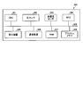
- FIG. 1 is a block diagram illustrating an example of a configuration of a pulse rate calculation system according to the embodiment.
- FIG. 2 is a diagram illustrating an example of the log storage unit.
- FIG. 3 is a diagram illustrating an example of a predetermined condition based on the number of steps.
- FIG. 4 is a diagram illustrating an example of a cumulative number of steps and a pulse rate time-series change.
- FIG. 5 is a diagram illustrating an example of the relationship between the pulse rate and the number of steps.
- FIG. 6 is a diagram illustrating another example of the relationship between the pulse rate and the number of steps.
- FIG. 7 is a diagram illustrating an example of a graph before and after correction of the pulse rate.
- FIG. 1 is a block diagram illustrating an example of a configuration of a pulse rate calculation system according to the embodiment.
- FIG. 2 is a diagram illustrating an example of the log storage unit.
- FIG. 3 is a diagram illustrating an example of a predetermined condition based on
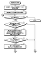
- FIG. 8 is a flowchart illustrating an example of a pulse rate calculation process according to the embodiment.
- FIG. 9 is a flowchart illustrating an example of a pulse rate calculation process according to the embodiment.
- FIG. 10 is a diagram illustrating an example of a computer that executes a pulse rate calculation program.
- FIG. 1 is a block diagram illustrating an example of a configuration of a pulse rate calculation system according to an embodiment.
- a pulse rate calculation system 1 illustrated in FIG. 1 includes a terminal device 10, a gateway device 100, and a server device 200.
- 1 shows an example in which the number of terminal devices 10 and gateway devices 100 is one, the number of terminal devices 10 and gateway devices 100 is not limited, and an arbitrary number of terminal devices 10 and gateway devices 100 may be used. You may have.
- the terminal device 10 is an example of an electronic device.
- the terminal device 10 and the gateway device 100 are connected so as to be able to communicate with each other via, for example, BLE (Bluetooth (registered trademark) Low Energy). Further, the gateway device 100 and the server device 200 are connected via a network N so that they can communicate with each other.
- a network N any type of communication network such as the Internet, LAN (Local Area Network), and VPN (Virtual Private Network) can be adopted regardless of wired or wireless.
- the terminal device 10 is, for example, a computer worn by a user who measures a pulse rate in daily life.
- the terminal device 10 is, for example, a wristwatch-type, badge-type, or tag-type terminal, and acquires data related to the user.
- the user is, for example, an on-site worker.
- the terminal device 10 acquires pulse wave data from the optical sensor and acquires acceleration data from the acceleration sensor.
- the terminal device 10 calculates the pulse rate based on the acquired pulse wave data.
- the terminal device 10 calculates the number of steps or the exercise intensity based on the acquired acceleration data.
- the terminal device 10 determines whether or not the current pulse rate satisfies a predetermined condition based on the calculated number of steps or exercise intensity when the calculated amount of change in the pulse rate is equal to or greater than a predetermined threshold.
- the terminal device 10 changes either the pulse rate at the time immediately before the change time at which the amount of change in the pulse rate is equal to or greater than a predetermined threshold, or the current pulse rate, depending on the determination result. Decide whether to use the pulse rate after the time.
- the terminal device 10 corrects the pulse rate based on the determined pulse rate. Thereby, the terminal device 10 can improve the measurement accuracy of the pulse rate.
- the gateway device 100 is, for example, a computer such as a smartphone or a relay station arranged in the vicinity of the user wearing the terminal device 10.
- the gateway device 100 receives log data transmitted from the terminal device 10 at regular intervals.
- the gateway device 100 transmits the received log data to the server device 200 via the network N.
- the server device 200 is a computer that collects information about the user wearing the terminal device 10.
- the server device 200 receives log data from the terminal device 10 via the network N and the gateway device 100.
- log data that is, user information
- the server apparatus 200 accumulates and stores the received log data.
- the terminal device 10 includes a communication unit 11, an optical sensor 12, an acceleration sensor 13, a display unit 14, a storage unit 15, and a control unit 17.
- the terminal device 10 may include various functional units included in a known computer, for example, functional units such as various input devices and output devices, in addition to the functional units illustrated in FIG.
- the communication unit 11 is realized by a wireless communication module such as BLE, for example.
- the communication unit 11 is a communication interface that is wirelessly connected to the gateway apparatus 100 and manages information communication with the gateway apparatus 100.
- the communication unit 11 may use a wireless communication module corresponding to a wireless LAN as a wireless communication module.
- the communication unit 11 transmits log data and the like input from the control unit 17 to the gateway device 100.
- the optical sensor 12 measures pulse waveform data (hereinafter referred to as “pulse wave data” as appropriate) used for pulse rate detection by irradiating a living body with light and receiving reflected light.
- the optical sensor 12 outputs the measured pulse wave data to the control unit 17.
- the acceleration sensor 13 is a device that detects acceleration.
- the acceleration sensor 13 is a triaxial acceleration sensor that measures acceleration in three axial directions, ie, an X-axis direction, a Y-axis direction, and a Z-axis direction that are orthogonal to each other.
- the acceleration sensor 13 outputs the measured acceleration data to the control unit 17.
- an acceleration detection method any method such as a semiconductor method, a mechanical method, or an optical method can be adopted.
- the acceleration sensor 13 is a triaxial acceleration sensor that measures acceleration in the triaxial direction, but may be a G (gravitation) sensor that detects acceleration in the gravitational direction.
- the display unit 14 is a display device for displaying the pulse rate.
- the display unit 14 is realized by, for example, a liquid crystal display as a display device.
- the display unit 14 notifies the user of the pulse rate, for example, by displaying the corrected pulse rate input from the control unit 17.
- the storage unit 15 is realized by a storage device such as a semiconductor memory element such as a RAM (Random Access Memory) and a flash memory (Flash Memory), for example.
- the storage unit 15 includes a log storage unit 16.
- the storage unit 15 stores information used for processing in the control unit 17.
- the log storage unit 16 stores log data such as date / time, pulse rate, and step count.
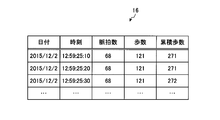
- FIG. 2 is a diagram illustrating an example of the log storage unit. As illustrated in FIG. 2, the log storage unit 16 includes items such as “date”, “time”, “pulse rate”, “step count”, and “cumulative step count”.
- “Date” is information indicating the date when the pulse rate and the number of steps were acquired.
- “Time” is information indicating the time when the pulse rate and the number of steps are acquired.
- Pulse rate is, for example, information indicating the pulse rate calculated based on pulse wave data for the past several seconds at the time. The number of seconds used for calculating the pulse rate may be any number of seconds, for example, a value such as 2 seconds or 4 seconds.
- “Number of steps” is information indicating the number of steps per unit time. The unit time is, for example, 1 minute.
- the “cumulative step count” is information indicating the cumulative step count since the start of the pulse rate calculation process.
- the control unit 17 is realized by, for example, a CPU (Central Processing Unit), an MPU (Micro Processing Unit), or the like executing a program stored in an internal storage device using the RAM as a work area.
- the control unit 17 may be realized by an integrated circuit such as ASIC (Application Specific Integrated Circuit) or FPGA (Field Programmable Gate Array).
- the control unit 17 includes an acquisition unit 18, a first calculation unit 19, a second calculation unit 20, a determination unit 21, a determination unit 22, a correction unit 23, a notification unit 24, and a communication control unit 25. And realizes or executes the functions and operations of information processing described below.
- the internal configuration of the control unit 17 is not limited to the configuration illustrated in FIG. 1, and may be another configuration as long as the information processing described later is performed.
- the acquisition unit 18 receives pulse wave data from the optical sensor 12 and acceleration data from the acceleration sensor 13. For example, the acquisition unit 18 starts acquiring pulse wave data and acceleration data when the pulse rate calculation process is started by an instruction from a switch (not shown). The acquisition unit 18 outputs the acquired pulse wave data to the first calculation unit 19 and outputs the acquired acceleration data to the second calculation unit 20.
- the acquisition unit 18 determines whether there is a request for stopping the pulse rate calculation process based on an instruction from a switch (not shown), for example. . When there is no stop request, the acquisition unit 18 continues to output the acquired pulse wave data and acceleration data. The acquisition part 18 complete
- the first calculation unit 19 calculates the pulse rate based on the input pulse wave data.
- the first calculator 19 calculates the pulse rate by, for example, converting the peak time interval of the pulse wave data into a value per unit time, for example, one minute.
- the first calculation unit 19 stores the calculated pulse rate in the log storage unit 16.
- the first calculation unit 19 outputs a determination instruction to the determination unit 21.
- the second calculation unit 20 calculates the number of steps based on the input acceleration data. For example, the second calculation unit 20 extracts a waveform peculiar to walking from acceleration data, and calculates the number of steps per minute, which is a unit time, based on the extracted waveform. The second calculation unit 20 stores the calculated number of steps in the log storage unit 16. In addition, the second calculation unit 20 calculates the cumulative number of steps by counting the number of steps since the pulse rate calculation process is started based on the extracted waveform. The second calculation unit 20 stores the calculated cumulative number of steps in the log storage unit 16.
- the second calculation unit 20 calculates the exercise intensity based on the acceleration data.
- the second calculation unit 20 holds an arithmetic expression for converting acceleration data into exercise intensity, and calculates the exercise intensity by substituting the acceleration data received from the acceleration sensor 13 into this arithmetic expression. To do.
- the determination unit 21 refers to the log storage unit 16 and determines whether or not there is a sudden change state in which the amount of change in the pulse rate is equal to or greater than a predetermined threshold. For example, the determination unit 21 acquires the pulse rate from the log storage unit 16 for the past 20 seconds from the present time. The determination part 21 determines whether it is in a sudden change state, for example using the following filter F1 as a predetermined threshold value. The filter F1 satisfies, for example, “(maximum change amount within the past 4 seconds from the current pulse rate) ⁇ ⁇ 14” or “(maximum change amount within the past 4 seconds from the current pulse rate) ⁇ + 14”.
- the filter is a sudden change state.
- the sudden change state is also expressed as a sudden change.
- the determination unit 21 refers to the log storage unit 16 and determines whether or not the current pulse rate satisfies a predetermined condition based on the number of steps.
- the determination unit 21 may use a predetermined condition based on exercise intensity. For example, the determination unit 21 acquires the cumulative number of steps for the past 20 seconds from the present time from the log storage unit 16. The determination unit 21 determines, for example, whether or not the current pulse rate satisfies the predetermined condition based on the number of steps using the condition shown in FIG. 3 as the predetermined condition based on the number of steps.
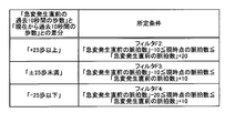
- FIG. 3 is a diagram illustrating an example of a predetermined condition based on the number of steps.
- FIG. 3 shows a predetermined condition corresponding to the difference between “the number of steps in the past 10 seconds immediately before the sudden change” and “the number of steps in the past 10 seconds from the present”.
- the determination unit 21 uses the next filter F2 as a predetermined condition.
- the filter F2 is, for example, “(pulse rate immediately before occurrence of sudden change) ⁇ 10 ⁇ current pulse rate ⁇ (pulse rate immediately before occurrence of sudden change) +20”.
- the determination unit 21 uses the next filter F3 as the predetermined condition.
- the filter F3 is, for example, “(pulse rate immediately before occurrence of sudden change) ⁇ 10 ⁇ current pulse rate ⁇ (pulse rate immediately before occurrence of sudden change) +10”.
- the determination unit 21 uses the next filter F4 as a predetermined condition.
- the filter F4 is, for example, “(pulse rate immediately before occurrence of sudden change) ⁇ 20 ⁇ current pulse rate ⁇ (pulse rate immediately before occurrence of sudden change) +10”.
- the determination unit 21 calculates a difference between “the number of steps in the past 10 seconds immediately before the sudden change” and “the number of steps in the past 10 seconds from the present”. That is, the determination unit 21 determines the number of steps or exercise intensity between the time point immediately before the change time point when the pulse rate change amount is equal to or greater than a predetermined threshold and the first predetermined time period, and the current time point before the first predetermined time period. The difference between the number of steps between them and the exercise intensity is calculated. The determination unit 21 determines whether or not the current pulse rate satisfies a predetermined condition corresponding to the calculated difference as shown in FIG. When the current pulse rate satisfies a predetermined condition corresponding to the difference, the determination unit 21 outputs a first determination instruction to the effect that the current pulse rate is used to the determination unit 22.
- Determining unit 21 selects the pulse rate at the time immediately before the change time when the current pulse rate does not satisfy the predetermined condition corresponding to the difference.
- the determination unit 21 outputs to the determination unit 22 a second determination instruction indicating that the pulse rate at the time immediately before the change time is selected.
- the determination unit 22 changes any one of the pulse rate at the time point immediately before the change time point or the current pulse rate according to the determination result in the determination unit 21. Decide whether to use the pulse rate after the time.
- the determination unit 22 receives a first determination instruction or a second determination instruction from the determination unit 21 as a determination result. When the first determination instruction is input, the determination unit 22 determines to use the current pulse rate, and outputs a first correction instruction to the effect that the current pulse rate is used to the correction unit 23.
- the determination unit 22 refers to the log storage unit 16 and the maximum value of the difference between the current pulse rate and the pulse rate from the current time to the second predetermined time before is within a predetermined value. It is determined whether or not. For example, the determination unit 22 determines whether or not the maximum value of the difference between the current pulse rate and the pulse rate within the past 6 seconds is within 6. When the maximum difference value is not within the predetermined value, the determination unit 22 determines to use the current pulse rate, and outputs a first correction instruction to the effect that the current pulse rate is used to the correction unit 23.
- the determination unit 22 determines whether or not the current pulse rate has returned to the vicinity of the pulse rate immediately before the change time. That is, the determination unit 22 first extracts the sign of the first value obtained by subtracting the current pulse rate from the extreme value of the pulse rate from the change time point to the current time point. In addition, the determination unit 22 extracts a sign of a second value obtained by subtracting the extreme value of the pulse rate from the change time point to the current time point from the pulse rate immediately before the change time point.
- the determination unit 22 is a code in which the sign of the first value is opposite to the sign of the second value, and the absolute value of the first value is a predetermined ratio of the absolute value of the second value, for example, It is determined whether it is 90% or more.
- the determination unit 22 is a code in which the sign of the first value is opposite to the sign of the second value, and the absolute value of the first value is equal to or greater than a predetermined ratio of the absolute value of the second value. In some cases, it is determined to use the current pulse rate, and a first correction instruction to the effect that the current pulse rate is used is output to the correction unit 23.
- the determination unit 22 has a code in which the sign of the first value is opposite to the sign of the second value, and the absolute value of the first value is not greater than or equal to a predetermined ratio of the absolute value of the second value. In this case, it is decided to use the pulse rate at the time immediately before the change time.
- the determination unit 22 makes the determination, the determination unit 22 outputs a second correction instruction to the effect that the pulse rate at the time immediately before the change time is used to the correction unit 23.
- the determining unit 22 may determine to use the current pulse rate as the pulse rate after the change time when the decrease in the number of steps or the exercise intensity is a predetermined value or more. For example, the determination unit 22 calculates the difference between the number of steps immediately before the change time and the current number of steps, and if the calculated difference is a predetermined value, for example, 20 steps or more, the current pulse rate is calculated as follows: Used as the pulse rate after the time of change. That is, if the determination unit 22 determines that the pace of walking has decreased, the pulse rate is likely to decrease, so the current pulse rate is employed. Moreover, the determination part 22 uses the pulse rate in the time immediately before a change time as a pulse rate after a change time, when the calculated difference is not more than predetermined value. That is, if the determination unit 22 determines that the pace of walking has not decreased, it is highly likely that the pulse rate has not changed significantly, so the pulse rate immediately before the change point is employed.
- the correction unit 23 corrects the pulse rate based on the pulse rate determined by the determination unit 22.
- the correction unit 23 receives the first correction instruction or the second correction instruction from the determination unit 22.
- the correction unit 23 does not perform correction and adopts the current pulse rate.
- the correction unit 23 determines whether or not the pulse rate is corrected for a predetermined time or more based on the pulse rate immediately before the change time point.
- the correction unit 23 corrects the pulse rate based on the current pulse rate when the pulse rate is corrected for a predetermined time or more. That is, the correction unit 23 employs the current pulse rate.
- the correction unit 23 corrects the pulse rate based on the pulse rate immediately before the change time when the pulse rate has not been corrected for a certain time or longer. That is, the correction unit 23 employs the pulse rate at the time immediately before the change time.
- the correction unit 23 outputs the corrected pulse rate to the notification unit 24 and outputs an end check instruction to the acquisition unit 18. Further, the correction unit 23 stores the corrected pulse rate in the log storage unit 16.
- the notification unit 24 displays the input corrected pulse rate on the display unit 14 to notify the user.
- the communication control unit 25 reads log data from the log storage unit 16 at a predetermined time interval, and transmits the read log data to the server device 200 via the communication unit 11 and the gateway device 100.
- the predetermined time interval can be, for example, 10 minutes.
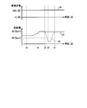
- FIG. 4 is a diagram illustrating an example of a cumulative number of steps and a pulse rate time-series change.
- the current time is time t1
- the time 4 seconds before the current time is time t2
- the sudden change occurs that is, the time of change is time t3
- the time 10 seconds before the current time is time t4
- the time 10 seconds before the time change is time t5.
- the cumulative number of steps has not changed as shown in the graph 31, that is, is in a stopped state.
- the determination unit 21 determines whether or not the pulse rate graph 32 is in a sudden change state using the filter F1 described above. That is, the determination unit 21 determines whether or not the pulse rate graph 32 satisfies the filter F1 between time t1 and time t2. Since the pulse rate graph 32 decreases by 30 bpm between time t1 and time t2, the filter F1 is satisfied. When satisfying the filter F1, the determination unit 21 refers to the log storage unit 16 and determines whether or not the current pulse rate satisfies a predetermined condition based on the number of steps.
- the determination unit 21 calculates that the difference between the number of steps from time t3 to time t5 and the number of steps from time t1 to time t4 is 0 steps. Since the difference is 0 steps, the determination unit 21 applies the filter F3 among the predetermined conditions illustrated in FIG. The determination unit 21 determines that the filter F3 is satisfied when the filter F3 is applied using the pulse rate at the time t3 immediately before the sudden change and the pulse rate at the current time t1. The determination unit 21 outputs a first determination instruction to use the current pulse rate to the determination unit 22 because the pulse rate at the current time satisfies the predetermined condition according to the difference, that is, the filter F3. In the example of FIG.
- the graph 32 changes greatly between the time t1 and the time t3, so that the filters F2 to F4 are not satisfied during this time, and the pulse rate at the time t3 is adopted. Therefore, a large change in the pulse rate between time t1 and time t3 is corrected as shown by the graph 33.
- FIG. 5 is a diagram illustrating an example of the relationship between the pulse rate and the number of steps.
- the pulse rate graph 41 shown in FIG. 5 when the pulse rate 42 at the current time t ⁇ b> 1 is compared with the pulse rate 43 at the past time point, the pulse rate 42 is smaller than the pulse rate 43.
- the step count graph 44 is constant including the step count 45 at the current time t1, that is, walking is performed at a constant speed. For this reason, in the example of FIG. 5, since walking is continuously performed at the current time t1, the pulse rate 43 of the past time is adopted as the pulse rate at the time t1, and the current pulse rate 42 is not adopted. .
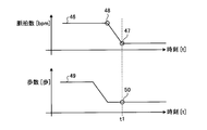
- FIG. 6 is a diagram showing another example of the relationship between the pulse rate and the number of steps.
- the pulse rate graph 46 shown in FIG. 6 when the pulse rate 47 at the current time t ⁇ b> 1 is compared with the pulse rate 48 at the past time, the pulse rate 47 is smaller than the pulse rate 48. Further, in the step count graph 49, the number of steps has decreased in the past, that is, the walking pace has decreased rather than the number of steps 50 at the current time t1. Therefore, in the example of FIG. 6, since the walking pace is decreasing at the current time t1, the current pulse rate 47 is adopted as the pulse rate at the time t1, and the pulse rate 48 at the past time is not adopted.
- FIG. 7 is a diagram illustrating an example of a graph before and after correction of the pulse rate.
- the time t11 is a state where a walk of 2 Hz or more for 2 minutes is performed
- the time t12 is a state of resting for 2 minutes
- the time t13 is a state of walking of 2 Hz or more for 5 minutes.
- time t14 indicates a state where the person is rested for 1 minute
- time t15 indicates a state where the arm is bent and extended for 5 minutes.
- a graph 61 shows a graph when the pulse rate calculation process according to the present embodiment is not performed, and a graph 62 shows a graph when the pulse rate calculation process according to the present embodiment is performed.
- the graph 63 shows a reference graph.
- the graph 61 greatly deviates from the graph 63 indicating the reference in a state where the pulse rate varies greatly.
- the graph 62 the fluctuation of the pulse rate is corrected and approaches the graph 63.
- the graph 62 is greatly deviated from the graph 63 indicating the reference in a state where the pulse rate varies greatly.
- the fluctuation of the pulse rate is corrected and approaches the graph 63. That is, the graph 62 has improved pulse rate measurement accuracy compared to the graph 61.
- 8 and 9 are flowcharts illustrating an example of the pulse rate calculation process according to the embodiment.
- the acquisition unit 18 of the terminal device 10 starts acquiring pulse wave data and acceleration data (step S1).
- the acquisition unit 18 outputs the acquired pulse wave data to the first calculation unit 19 and outputs the acquired acceleration data to the second calculation unit 20.
- the first calculation unit 19 starts calculating the pulse rate based on the input pulse wave data (step S2).
- the first calculation unit 19 stores the calculated pulse rate in the log storage unit 16.
- the first calculation unit 19 outputs a determination instruction to the determination unit 21.
- the second calculation unit 20 When the acceleration data is input from the acquisition unit 18, the second calculation unit 20 starts calculating the number of steps based on the input acceleration data (step S2).
- the second calculation unit 20 stores the calculated number of steps in the log storage unit 16.
- the 2nd calculation part 20 starts calculation of an accumulated step by counting the number of steps after starting a pulse rate calculation process based on the extracted waveform.
- the second calculation unit 20 stores the calculated cumulative number of steps in the log storage unit 16.
- the acquisition unit 18 determines whether or not there is a request to stop the pulse rate calculation process (step S3). If there is no stop request (No at Step S3), the acquisition unit 18 continues to output the acquired pulse wave data and acceleration data.
- the determination unit 21 refers to the log storage unit 16 and determines whether or not the sudden change state in which the amount of change in the pulse rate is equal to or greater than a predetermined threshold (step S4). ). If the change amount of the pulse rate is not equal to or greater than the predetermined threshold (No at Step S4), the determination unit 21 outputs a first determination instruction to the effect that the current pulse rate is used to the determination unit 22. When the first determination instruction is input, the determination unit 22 outputs the first correction instruction to the correction unit 23 and proceeds to step S10.
- step S4 If the amount of change in the pulse rate is equal to or greater than the predetermined threshold (step S4: affirmative), the determination unit 21 refers to the log storage unit 16 and refers to the number of steps from the time immediately before the change time to the first predetermined time before. And the difference between the current step number and the number of steps from the first predetermined time before is calculated (step S5). The determination unit 21 determines whether or not the current pulse rate satisfies a predetermined condition corresponding to the calculated difference (step S6). When the current pulse rate satisfies the predetermined condition corresponding to the difference (step S6: affirmative), the determination unit 21 outputs a first determination instruction to the effect that the current pulse rate is used to the determination unit 22. When the first determination instruction is input, the determination unit 22 outputs the first correction instruction to the correction unit 23 and proceeds to step S10.
- the determination unit 21 selects the pulse rate immediately before the change time (Step S7).
- the determination unit 21 outputs to the determination unit 22 a second determination instruction indicating that the pulse rate at the time immediately before the change time is selected.
- the first determination instruction or the second determination instruction is input to the determination unit 22 as a determination result from the determination unit 21.
- the determination unit 22 determines to use the current pulse rate, and outputs a first correction instruction to the effect that the current pulse rate is used to the correction unit 23.
- the determination unit 22 refers to the log storage unit 16, and the maximum value of the difference between the current pulse rate and the pulse rate from the current time to the second predetermined time before is within a predetermined value. It is determined whether or not there is (step S8). If the maximum difference is not within the predetermined value (No at Step S8), the determination unit 22 determines to use the current pulse rate, and corrects the first correction instruction to use the current pulse rate. 23, and proceeds to step S10.
- step S8 When the maximum value of the difference is within the predetermined value (step S8: affirmative), the determination unit 22 has a code in which the sign of the first value is opposite to the sign of the second value, and the first value It is determined whether the absolute value of the value is equal to or greater than a predetermined ratio of the absolute value of the second value (step S9).
- the determination unit 22 has a sign in which the sign of the first value and the sign of the second value are opposite, and the absolute value of the first value is equal to or greater than a predetermined ratio of the absolute value of the second value.
- step S9 affirmative
- the determination unit 22 has a code in which the sign of the first value is opposite to the sign of the second value, and the absolute value of the first value is not greater than or equal to a predetermined ratio of the absolute value of the second value. (Step S9: No), it is determined to use the pulse rate at the time immediately before the change time.
- the determination unit 22 outputs a second correction instruction to the effect that the pulse rate at the time immediately before the change time is used to the correction unit 23.
- the first correction instruction or the second correction instruction is input to the correction unit 23 from the determination unit 22.
- the correction unit 23 corrects the pulse rate based on the current pulse rate (step S10). That is, since the correction unit 23 employs the current pulse rate, the correction is not substantially performed.
- the correction unit 23 determines whether or not the pulse rate is corrected for a predetermined time or more based on the pulse rate at the time immediately before the change time (step S11).
- the correction unit 23 corrects the pulse rate based on the current pulse rate (step S10) when the pulse rate is corrected for a certain time or more (step S11: Yes). When the pulse rate has not been corrected for a certain time or longer (No at Step S11), the correction unit 23 corrects the pulse rate based on the pulse rate immediately before the change time (Step S12). The correction unit 23 outputs the corrected pulse rate to the notification unit 24. When the corrected pulse rate is input from the correction unit 23, the notification unit 24 displays the input corrected pulse rate on the display unit 14 and notifies the user (step S13). The correction unit 23 outputs an end check instruction to the acquisition unit 18 and returns to step S3. Further, the correction unit 23 stores the corrected pulse rate in the log storage unit 16.
- the terminal device 10 can improve the measurement accuracy of the pulse rate. That is, the terminal device 10 always switches the presence / absence of correction using information on the number of steps, exercise intensity, and the amount of change thereof. In addition, the terminal device 10 changes the correction parameter so that even if an error occurs suddenly in a state where the motion state is constantly changing, only the pulse rate including the error is in a state before the sudden error occurs. Correct to pulse rate. Thereby, the terminal device 10 can improve the measurement accuracy of the pulse rate.
- the terminal device 10 acquires pulse wave data from the optical sensor and acquires acceleration data from the acceleration sensor. Moreover, the terminal device 10 calculates a pulse rate based on the acquired pulse wave data. Moreover, the terminal device 10 calculates the number of steps or the exercise intensity based on the acquired acceleration data. Further, the terminal device 10 determines whether or not the current pulse rate satisfies a predetermined condition based on the calculated number of steps or exercise intensity when the calculated amount of change in the pulse rate is equal to or greater than a predetermined threshold. . Further, the terminal device 10 determines which one of the pulse rate at the time point immediately before the change time point when the change amount of the pulse rate is equal to or greater than a predetermined threshold or the current pulse rate, depending on the determination result. Determine whether to use the pulse rate after the time of change. Moreover, the terminal device 10 corrects the pulse rate based on the determined pulse rate. As a result, the pulse rate measurement accuracy can be improved.
- the terminal device 10 determines to use the current pulse rate as the pulse rate after the change time. As a result, the pulse rate measurement accuracy can be improved.
- the terminal device 10 determines a predetermined condition according to a difference between the number of steps or exercise intensity between a time immediately before the change time and a predetermined time before and the number of steps or exercise intensity between the current time and a predetermined time before, It is determined whether or not the current pulse rate is satisfied. As a result, the pulse rate measurement accuracy can be improved.
- the terminal device 10 further determines the change time point from the sign of the first value obtained by subtracting the current pulse rate from the extreme value of the pulse rate from the change time point to the current time point, and the pulse rate immediately before the change time point.
- the terminal device 10 has a sign in which the sign of the first value is opposite to the sign of the second value, and the absolute value of the first value is a predetermined ratio of the absolute value of the second value.
- the terminal device 10 corrects the pulse rate based on the current pulse rate when the pulse rate is corrected for a certain time or more based on the pulse rate immediately before the change time. As a result, the pulse rate measurement accuracy can be improved.
- the example is described in which the user is an on-site worker, but the present invention is not limited to this.
- the user may be an elderly person, and in this case, a family living in a remote place can watch over the elderly person.
- each component of each part illustrated does not necessarily need to be physically configured as illustrated.
- the specific form of distribution / integration of each unit is not limited to that shown in the figure, and all or a part thereof may be functionally or physically distributed / integrated in arbitrary units according to various loads or usage conditions. Can be configured.
- the first calculation unit 19 and the second calculation unit 20 may be integrated.
- the illustrated processes are not limited to the above-described order, and may be performed at the same time as long as the process contents are not contradictory, or may be performed in a different order.
- each device may be executed entirely or arbitrarily on a CPU (or a microcomputer such as MPU or MCU (Micro Controller Unit)).
- various processing functions may be executed in whole or in any part on a program that is analyzed and executed by a CPU (or a microcomputer such as an MPU or MCU) or on hardware based on wired logic. Needless to say, it is good.
- FIG. 10 is a diagram illustrating an example of a computer that executes a pulse rate calculation program.
- the computer 300 includes a CPU 301 that executes various arithmetic processes, an optical sensor 302 that measures pulse waves, and an acceleration sensor 303 that measures acceleration. Further, the computer 300 includes an RTC (Real Time Clock) 304 that outputs time information, a display device 305 that displays a pulse rate, and a communication device 306 for wirelessly connecting to other information processing devices and the like.
- the computer 300 also includes a RAM 307 that temporarily stores various types of information and a flash memory 308. Each device 301 to 308 is connected to a bus 309.
- a pulse rate calculation program having the same function as the unit is stored. Further, the flash memory 308 stores the log storage unit 16 and various data for realizing the pulse rate calculation program.
- the optical sensor 302 outputs the measured pulse wave data to the CPU 301.
- the acceleration sensor 303 outputs the measured acceleration data to the CPU 301.
- the RTC 304 outputs time information to the CPU 301.
- the display device 305 displays, for example, the pulse rate.
- the communication device 306 has the same function as the communication unit 11 illustrated in FIG. 1 and is connected to the gateway device 100 to exchange various information with the gateway device 100.
- the CPU 301 reads out each program stored in the flash memory 308, develops it in the RAM 307, and executes it to perform various processes.
- these programs include the acquisition unit 18, the first calculation unit 19, the second calculation unit 20, the determination unit 21, the determination unit 22, the correction unit 23, the notification unit 24, and the communication control unit illustrated in FIG. 25 can function.
- the above pulse rate calculation program is not necessarily stored in the flash memory 308.
- the computer 300 may read and execute a program stored in a storage medium readable by the computer 300.
- the storage medium readable by the computer 300 corresponds to, for example, a portable recording medium such as a CD-ROM, a DVD disk, a USB (Universal Serial Bus) memory, a semiconductor memory such as a flash memory, a hard disk drive, and the like.
- the pulse rate calculation program may be stored in a device connected to a public line, the Internet, a LAN, or the like, and the computer 300 may read and execute the pulse rate calculation program from these.
Landscapes
- Health & Medical Sciences (AREA)
- Life Sciences & Earth Sciences (AREA)
- Engineering & Computer Science (AREA)
- Cardiology (AREA)
- Pathology (AREA)
- Animal Behavior & Ethology (AREA)
- Physiology (AREA)
- Biophysics (AREA)
- Veterinary Medicine (AREA)
- Biomedical Technology (AREA)
- Heart & Thoracic Surgery (AREA)
- Medical Informatics (AREA)
- Molecular Biology (AREA)
- Surgery (AREA)
- Physics & Mathematics (AREA)
- General Health & Medical Sciences (AREA)
- Public Health (AREA)
- Signal Processing (AREA)
- Measuring Pulse, Heart Rate, Blood Pressure Or Blood Flow (AREA)
Abstract
脈拍数の測定精度を向上させることができる電子機器および脈拍数算出プログラムを提供する。電子機器(10)は、取得部(18)と、第1算出部(19)と、第2算出部(20)と、判定部(21)と、決定部(22)と、補正部(23)とを有する。取得部(18)は、光センサから脈波データを取得し加速度センサから加速度データを取得する。第1算出部(19)は、脈波データから脈拍数を算出する。第2算出部(20)は、加速度データから歩数を算出する。判定部(21)は、脈拍数の変化量が所定の閾値以上となる場合に、歩数に基づく所定条件を現時点の脈拍数が満たすか否かを判定する。決定部(22)は、判定結果に応じて脈拍数の変化量が所定の閾値以上となる変化時点直前の脈拍数、または、現時点の脈拍数のうち、いずれの脈拍数を変化時点より後の脈拍数として用いるかを決定する。補正部(23)は、決定された脈拍数に基づいて脈拍数を補正する。
Description
本発明は、電子機器および脈拍数算出プログラムに関する。
従来、被験者が運動を行っている状態において、脈拍数を計測することが行われている。運動時における脈拍数は、ある程度の範囲に収まるため、測定された脈拍数が実際の脈拍数と異なる場合には、ベースラインを求めて補正することができる。
しかしながら、日常生活における脈拍数を計測する場合には、走る等の活動量が高い状態と、安静時の活動量が低い状態とが混在しているため、ベースラインを求めて補正すると、多くの時間において大きな誤差が発生し、測定精度を向上させることが困難である。
一つの側面では、本発明は、脈拍数の測定精度を向上させることができる電子機器および脈拍数算出プログラムを提供することにある。
一つの態様では、電子機器は、取得部と、第1算出部と、第2算出部と、判定部と、決定部と、補正部とを有する。取得部は、光センサから脈波データを取得し、加速度センサから加速度データを取得する。第1算出部は、取得された前記脈波データに基づいて、脈拍数を算出する。第2算出部は、取得された前記加速度データに基づいて、歩数または運動強度を算出する。判定部は、算出された前記脈拍数の変化量が所定の閾値以上となる場合に、算出された前記歩数または運動強度に基づく所定条件を、現時点における前記脈拍数が満たすか否かを判定する。決定部は、前記判定の結果に応じて、前記脈拍数の変化量が前記所定の閾値以上となる変化時点の直前の時点における前記脈拍数、または、現時点における前記脈拍数のうち、いずれの前記脈拍数を、前記変化時点より後の前記脈拍数として用いるかを決定する。補正部は、決定された前記脈拍数に基づいて、前記脈拍数を補正する。
脈拍数の測定精度を向上させることができる。
以下、図面に基づいて、本願の開示する電子機器および脈拍数算出プログラムの実施例を詳細に説明する。なお、本実施例により、開示技術が限定されるものではない。また、以下の実施例は、矛盾しない範囲で適宜組みあわせてもよい。
図1は、実施例の脈拍数算出システムの構成の一例を示すブロック図である。図1に示す脈拍数算出システム1は、端末装置10と、ゲートウェイ装置100と、サーバ装置200とを有する。なお、図1では、端末装置10およびゲートウェイ装置100の数を1つとした例を示したが、端末装置10およびゲートウェイ装置100の数は限定されず、任意の数の端末装置10およびゲートウェイ装置100を有してもよい。なお、端末装置10は、電子機器の一例である。
端末装置10およびゲートウェイ装置100の間は、例えばBLE(Bluetooth(登録商標) Low Energy)を介して相互に通信可能に接続される。また、ゲートウェイ装置100およびサーバ装置200の間は、ネットワークNを介して相互に通信可能に接続される。かかるネットワークNには、有線または無線を問わず、インターネットを始め、LAN(Local Area Network)やVPN(Virtual Private Network)などの任意の種類の通信網を採用できる。
端末装置10は、例えば、日常生活における脈拍数が計測されるユーザが装着するコンピュータである。端末装置10は、例えば、腕時計型、バッジ型およびタグ型等の端末であり、ユーザに関するデータを取得する。なお、ユーザは、例えば現場の作業者である。端末装置10は、光センサから脈波データを取得し、加速度センサから加速度データを取得する。端末装置10は、取得された脈波データに基づいて、脈拍数を算出する。また、端末装置10は、取得された加速度データに基づいて、歩数または運動強度を算出する。端末装置10は、算出された脈拍数の変化量が所定の閾値以上となる場合に、算出された歩数または運動強度に基づく所定条件を、現時点における脈拍数が満たすか否かを判定する。端末装置10は、判定の結果に応じて、脈拍数の変化量が所定の閾値以上となる変化時点の直前の時点における脈拍数、または、現時点における脈拍数のうち、いずれの脈拍数を、変化時点より後の脈拍数として用いるかを決定する。端末装置10は、決定された脈拍数に基づいて、脈拍数を補正する。これにより、端末装置10は、脈拍数の測定精度を向上させることができる。
ゲートウェイ装置100は、例えば、端末装置10を装着したユーザの近傍に配置されるスマートフォンや中継用のステーション等のコンピュータである。ゲートウェイ装置100は、一定時間ごとに端末装置10から送信されるログデータを受信する。ゲートウェイ装置100は、受信したログデータを、ネットワークNを介してサーバ装置200に送信する。
サーバ装置200は、端末装置10を装着したユーザの情報を収集するコンピュータである。サーバ装置200は、ネットワークNおよびゲートウェイ装置100を介して、端末装置10からログデータを受信する。サーバ装置200は、ログデータ、つまりユーザの情報を受信すると、受信したログデータを蓄積して記憶する。
次に、端末装置10の構成について説明する。図1に示すように、端末装置10は、通信部11と、光センサ12と、加速度センサ13と、表示部14と、記憶部15と、制御部17とを有する。なお、端末装置10は、図1に示す機能部以外にも既知のコンピュータが有する各種の機能部、例えば各種の入力デバイスや出力デバイス等の機能部を有することとしてもかまわない。
通信部11は、例えば、BLE等の無線通信モジュールによって実現される。通信部11は、ゲートウェイ装置100と無線で接続され、ゲートウェイ装置100との間で情報の通信を司る通信インタフェースである。なお、通信部11は、無線通信モジュールとして、無線LANに対応する無線通信モジュールを用いてもよい。通信部11は、制御部17から入力されたログデータ等をゲートウェイ装置100に送信する。
光センサ12は、生体に対して光を照射して反射光を受光することで、脈拍数の検出に用いられる脈波の波形データ(以下適宜「脈波データ」と呼ぶ)を計測する。光センサ12は、計測した脈波データを制御部17に出力する。
加速度センサ13は、加速度を検出するデバイスである。例えば、加速度センサ13は、互いに直交するX軸方向、Y軸方向、Z軸方向の3軸方向の加速度を計測する3軸加速度センサである。加速度センサ13は、計測した加速度データを制御部17に出力する。加速度の検出方式には、半導体式を始め、機械式や光学式などの任意の方式を採用できる。なお、以下では、加速度センサ13は、3軸方向の加速度を測定する3軸加速度センサとしたが、重力方向の加速度を検出するG(gravitation)センサとしてもよい。
表示部14は、脈拍数を表示するための表示デバイスである。表示部14は、例えば、表示デバイスとして液晶ディスプレイ等によって実現される。表示部14は、例えば、制御部17から入力される補正後の脈拍数を表示することで、ユーザに脈拍数を通知する。
記憶部15は、例えば、RAM(Random Access Memory)、フラッシュメモリ(Flash Memory)等の半導体メモリ素子等の記憶装置によって実現される。記憶部15は、ログ記憶部16を有する。また、記憶部15は、制御部17での処理に用いる情報を記憶する。
ログ記憶部16は、日時、脈拍数および歩数等のログデータを記憶する。図2は、ログ記憶部の一例を示す図である。図2に示すように、ログ記憶部16は、「日付」、「時刻」、「脈拍数」、「歩数」、「累積歩数」といった項目を有する。
「日付」は、脈拍数および歩数が取得された日付を示す情報である。「時刻」は、脈拍数および歩数が取得された時刻を示す情報である。「脈拍数」は、例えば、当該時刻において、過去数秒間の脈波データに基づいて算出された脈拍数を示す情報である。なお、脈拍数の算出に用いる秒数は任意の秒数でよく、例えば2秒や4秒といった値とすることができる。「歩数」は、単位時間当たりの歩数を示す情報である。単位時間は、例えば1分間である。「累積歩数」は、脈拍数算出処理を開始してからの累積歩数を示す情報である。
制御部17は、例えば、CPU(Central Processing Unit)やMPU(Micro Processing Unit)等によって、内部の記憶装置に記憶されているプログラムがRAMを作業領域として実行されることにより実現される。また、制御部17は、例えば、ASIC(Application Specific Integrated Circuit)やFPGA(Field Programmable Gate Array)等の集積回路により実現されるようにしてもよい。制御部17は、取得部18と、第1算出部19と、第2算出部20と、判定部21と、決定部22と、補正部23と、通知部24と、通信制御部25とを有し、以下に説明する情報処理の機能や作用を実現または実行する。なお、制御部17の内部構成は、図1に示した構成に限られず、後述する情報処理を行う構成であれば他の構成であってもよい。
取得部18には、光センサ12から脈波データが入力され、加速度センサ13から加速度データが入力される。取得部18は、例えば図示しないスイッチによる指示による脈拍数算出処理が開始されると、脈波データおよび加速度データの取得を開始する。取得部18は、取得した脈波データを第1算出部19に出力し、取得した加速度データを第2算出部20に出力する。
また、取得部18は、脈拍数算出処理の開始後に、補正部23から終了チェック指示が入力されると、例えば図示しないスイッチによる指示による脈拍数算出処理の停止要求があるか否かを判定する。取得部18は、停止要求がない場合には、引き続き取得した脈波データおよび加速度データの出力を継続する。取得部18は、停止要求がある場合には、脈拍数算出処理を終了する。
第1算出部19は、取得部18から脈波データが入力されると、入力された脈波データに基づいて、脈拍数を算出する。第1算出部19は、例えば、脈波データのピークの時間間隔を単位時間、例えば、1分間当たりの値に換算することによって、脈拍数を算出する。第1算出部19は、算出した脈拍数をログ記憶部16に記憶する。また、第1算出部19は、判定指示を判定部21に出力する。
第2算出部20は、取得部18から加速度データが入力されると、入力された加速度データに基づいて、歩数を算出する。第2算出部20は、例えば、加速度データから歩行に特有の波形を抽出し、抽出した波形に基づいて、単位時間である1分間当たりの歩数を算出する。第2算出部20は、算出した歩数をログ記憶部16に記憶する。また、第2算出部20は、抽出した波形に基づいて、脈拍数算出処理を開始してからの歩数を計数することで累積歩数を算出する。第2算出部20は、算出した累積歩数をログ記憶部16に記憶する。
なお、以下の説明では、歩数を用いて説明するが、歩数に代えて運動強度を用いてもよいし、歩数および運動強度を用いてもよい。第2算出部20は、運動強度を用いる場合には、加速度データに基づいて、運動強度を算出する。この場合には、第2算出部20は、例えば、加速度データを運動強度に換算する演算式を保持し、加速度センサ13から受け取った加速度データをこの演算式に代入することによって、運動強度を算出する。
判定部21は、第1算出部19から判定指示が入力されると、ログ記憶部16を参照し、脈拍数の変化量が所定の閾値以上である急変状態か否かを判定する。判定部21は、例えば、ログ記憶部16から、現在から過去20秒間の脈拍数を取得する。判定部21は、例えば、所定の閾値として次のフィルタF1を用いて急変状態か否かを判定する。フィルタF1は、例えば、「(現時点の脈拍数から過去4秒間以内の最大変化量)≦-14」、または、「(現時点の脈拍数から過去4秒間以内の最大変化量)≧+14」を満たす場合に、急変状態とするフィルタである。なお、以下の説明では、急変状態を急変とも表現する。判定部21は、脈拍数の変化量が所定の閾値以上でない場合には、決定部22に現時点の脈拍数を用いる旨の第1判定指示を出力する。
判定部21は、脈拍数の変化量が所定の閾値以上である場合には、ログ記憶部16を参照し、歩数に基づく所定条件を、現時点における脈拍数が満たすか否かを判定する。なお、判定部21は、運動強度に基づく所定条件を用いてもよい。判定部21は、例えば、ログ記憶部16から、現在から過去20秒間の累積歩数を取得する。判定部21は、例えば、歩数に基づく所定条件として図3に示す条件を用いて、歩数に基づく所定条件を現時点における脈拍数が満たすか否かを判定する。
図3は、歩数に基づく所定条件の一例を示す図である。図3は、「急変発生直前の過去10秒間の歩数」と「現在から過去10秒間の歩数」との差分に応じた所定条件を示す。判定部21は、例えば、差分が「+25歩以上」である場合には、所定条件として次のフィルタF2を用いる。フィルタF2は、例えば、「(急変発生直前の脈拍数)-10≦現時点の脈拍数≦(急変発生直前の脈拍数)+20」である。判定部21は、例えば、差分が「±25歩未満」である場合には、所定条件として次のフィルタF3を用いる。フィルタF3は、例えば、「(急変発生直前の脈拍数)-10≦現時点の脈拍数≦(急変発生直前の脈拍数)+10」である。判定部21は、例えば、差分が「-25歩以下」である場合には、所定条件として次のフィルタF4を用いる。フィルタF4は、例えば、「(急変発生直前の脈拍数)-20≦現時点の脈拍数≦(急変発生直前の脈拍数)+10」である。
判定部21は、「急変発生直前の過去10秒間の歩数」と「現在から過去10秒間の歩数」との差分を算出する。すなわち、判定部21は、脈拍数の変化量が所定の閾値以上となる変化時点の直前の時点から第1所定時間前までの間における歩数または運動強度と、現時点から第1所定時間前までの間における歩数または運動強度との差分を算出する。判定部21は、図3に示すような算出した差分に応じた所定条件を、現時点における脈拍数が満たすか否かを判定する。判定部21は、差分に応じた所定条件を、現時点における脈拍数が満たす場合には、決定部22に現時点の脈拍数を用いる旨の第1判定指示を出力する。
判定部21は、差分に応じた所定条件を、現時点における脈拍数が満たさない場合には、変化時点の直前の時点における脈拍数を選択する。判定部21は、変化時点の直前の時点における脈拍数を選択した旨の第2判定指示を決定部22に出力する。
図1の説明に戻って、決定部22は、判定部21における判定の結果に応じて、変化時点の直前の時点における脈拍数、または、現時点における脈拍数のうち、いずれの脈拍数を、変化時点より後の脈拍数として用いるかを決定する。決定部22は、判定部21から判定の結果として、第1判定指示または第2判定指示が入力される。決定部22は、第1判定指示が入力されると、現時点の脈拍数を用いることを決定し、現時点の脈拍数を用いる旨の第1補正指示を補正部23に出力する。
決定部22は、第2判定指示が入力されると、ログ記憶部16を参照し、現時点の脈拍数と、現時点から第2所定時間前までの脈拍数との差分の最大値が所定値以内であるか否かを判定する。決定部22は、例えば、現時点の脈拍数と、過去6秒以内の脈拍数との差分の最大値が6以内であるか否かを判定する。決定部22は、差分の最大値が所定値以内でない場合には、現時点の脈拍数を用いることを決定し、現時点の脈拍数を用いる旨の第1補正指示を補正部23に出力する。
決定部22は、差分の最大値が所定値以内である場合には、現時点の脈拍数が変化時点の直前の時点における脈拍数付近まで戻っているか否かを判定する。すなわち、決定部22は、まず、変化時点から現時点までにおける脈拍数の極値から、現時点における脈拍数を引いた第1の値の符号を抽出する。また、決定部22は、変化時点の直前の時点における脈拍数から、変化時点から現時点までにおける脈拍数の極値を引いた第2の値の符号を抽出する。
決定部22は、第1の値の符号と、第2の値の符号とが逆の符号であり、かつ、第1の値の絶対値が第2の値の絶対値の所定の割合、例えば90%以上であるか否かを判定する。決定部22は、第1の値の符号と、第2の値の符号とが逆の符号であり、かつ、第1の値の絶対値が第2の値の絶対値の所定の割合以上である場合には、現時点の脈拍数を用いることを決定し、現時点の脈拍数を用いる旨の第1補正指示を補正部23に出力する。
決定部22は、第1の値の符号と、第2の値の符号とが逆の符号であり、かつ、第1の値の絶対値が第2の値の絶対値の所定の割合以上でない場合には、変化時点の直前の時点における脈拍数を用いることを決定する。決定部22は、当該決定をすると、変化時点の直前の時点における脈拍数を用いる旨の第2補正指示を補正部23に出力する。
また、決定部22は、歩数または運動強度の低下量が所定値以上である場合には、現時点における脈拍数を、変化時点より後の脈拍数として用いることを決定するようにしてもよい。例えば、決定部22は、変化時点の直前の時点における歩数と、現時点における歩数との差分を算出し、算出した差分が所定値、例えば20歩以上である場合には、現時点における脈拍数を、変化時点より後の脈拍数として用いる。すなわち、決定部22は、歩行のペースが下がったと判定すると、脈拍数は下がる可能性が高いため、現時点における脈拍数を採用する。また、決定部22は、算出した差分が所定値以上でない場合には、変化時点の直前の時点における脈拍数を、変化時点より後の脈拍数として用いる。すなわち、決定部22は、歩行のペースが下がっていないと判定すると、脈拍数は大きく変化していない可能性が高いため、変化時点の直前の時点における脈拍数を採用する。
補正部23は、決定部22で決定された脈拍数に基づいて脈拍数を補正する。補正部23には、決定部22から第1補正指示または第2補正指示が入力される。補正部23は、第1補正指示が入力されると、補正を行わず現時点の脈拍数を採用する。補正部23は、第2補正指示が入力されると、変化時点の直前の時点における脈拍数に基づいて、一定時間以上脈拍数を補正しているか否かを判定する。
補正部23は、一定時間以上脈拍数を補正している場合には、現時点における脈拍数に基づいて脈拍数を補正する。すなわち、補正部23は、現時点における脈拍数を採用する。補正部23は、一定時間以上脈拍数を補正していない場合には、変化時点の直前の時点における脈拍数に基づいて、脈拍数を補正する。すなわち、補正部23は、変化時点の直前の時点における脈拍数を採用する。補正部23は、補正後の脈拍数を通知部24に出力するとともに、終了チェック指示を取得部18に出力する。また、補正部23は、補正後の脈拍数をログ記憶部16に記憶する。
通知部24は、補正部23から補正後の脈拍数が入力されると、入力された補正後の脈拍数を表示部14に表示させてユーザに通知する。
通信制御部25は、所定の時間間隔でログ記憶部16からログデータを読み出して、読み出したログデータを、通信部11およびゲートウェイ装置100を介して、サーバ装置200に送信する。なお、所定の時間間隔は、例えば、10分とすることができる。
ここで、図4を用いて判定部21での処理について説明する。図4は、累積歩数と脈拍数時系列変化の一例を示す図である。図4に示すグラフでは、現時点を時刻t1、現時点から4秒前を時刻t2、急変発生、つまり変化時点を時刻t3、現時点から10秒前を時刻t4、変化時点から10秒前を時刻t5とする。また、累積歩数は、グラフ31に示すように変化していない、つまり停止している状態である。
まず、判定部21は、脈拍数のグラフ32に対して、上述のフィルタF1を用いて急変状態か否かを判定する。すなわち、判定部21は、脈拍数のグラフ32が、時刻t1と時刻t2との間でフィルタF1を満たすか否かを判定する。脈拍数のグラフ32は、時刻t1と時刻t2との間で30bpm減少しているので、フィルタF1を満たす。判定部21は、フィルタF1を満たす場合には、ログ記憶部16を参照し、歩数に基づく所定条件を、現時点における脈拍数が満たすか否かを判定する。
判定部21は、時刻t3から時刻t5間の歩数と、時刻t1から時刻t4間の歩数との差分が0歩であると算出する。判定部21は、差分が0歩であるので、図3に示す所定条件のうちフィルタF3を適用する。判定部21は、急変直前である時刻t3の脈拍数と、現時点の時刻t1における脈拍数とを用いてフィルタF3を適用すると、フィルタF3を満たすと判定する。判定部21は、差分に応じた所定条件、つまりフィルタF3を、現時点における脈拍数が満たすので、決定部22に現時点の脈拍数を用いる旨の第1判定指示を出力する。なお、図4の例では、グラフ32は時刻t1と時刻t3との間で大きく変化しているため、この間ではフィルタF2~F4を満たさず、時刻t3の脈拍数が採用される。従って、時刻t1から時刻t3の間の脈拍数はグラフ33で示すように大きな変化が補正される。
次に、図5および図6を用いて脈拍数と歩数との関係について説明する。図5は、脈拍数と歩数との関係の一例を示す図である。図5に示す脈拍数のグラフ41は、現時点の時刻t1における脈拍数42と、過去の時点の脈拍数43とを比較すると、脈拍数43に比べて脈拍数42の方が減少している。これに対し、歩数のグラフ44は、現時点の時刻t1における歩数45を含め一定である、つまり、一定の速度で歩行が行われている。このため、図5の例では、現時点の時刻t1において歩行が継続して行われているので、時刻t1の脈拍数として過去の時点の脈拍数43を採用し、現時点の脈拍数42は採用しない。
図6は、脈拍数と歩数との関係の他の一例を示す図である。図6に示す脈拍数のグラフ46は、現時点の時刻t1における脈拍数47と、過去の時点の脈拍数48とを比較すると、脈拍数48に比べて脈拍数47の方が減少している。また、歩数のグラフ49は、現時点の時刻t1における歩数50となるより過去に歩数が減少している、つまり、歩行ペースが低下している。このため、図6の例では、現時点の時刻t1において歩行ペースが低下しているので、時刻t1の脈拍数として現在の脈拍数47を採用し、過去の時点の脈拍数48は採用しない。
続いて、図7を用いて脈拍数の補正前後のグラフについて説明する。図7は、脈拍数の補正前後のグラフの一例を示す図である。図7の例では、時間t11は2分間の2Hz以上の歩行が行われている状態、時間t12は2分間安静にしている状態、時間t13は5分間の2Hz以上の歩行が行われている状態を示す。また、図7の例では、時間t14は1分間安静にしている状態、時間t15は5分間の腕曲げ伸ばしが行われている状態を示す。
図7では、グラフ61が本実施例による脈拍数算出処理を行わない場合のグラフを示し、グラフ62が本実施例による脈拍数算出処理を行った場合のグラフを示す。なお、グラフ63は、リファレンスのグラフを示す。図7に示すように、歩行が行われている時間t11の領域64では、グラフ61は、脈拍数が大きく変動している状態でリファレンスを示すグラフ63と大きく乖離している。これに対し、グラフ62では、脈拍数の変動が補正され、グラフ63に近づいている。同様に、時間t13の領域65では、グラフ61は、脈拍数が大きく変動している状態でリファレンスを示すグラフ63と大きく乖離している。これに対し、グラフ62では、脈拍数の変動が補正され、グラフ63に近づいている。すなわち、グラフ62は、グラフ61と比べて、脈拍数の測定精度が向上している。
次に、実施例の脈拍数算出システム1の動作について説明する。図8および図9は、実施例の脈拍数算出処理の一例を示すフローチャートである。
端末装置10の取得部18は、脈拍数算出処理が開始されると、脈波データおよび加速度データの取得を開始する(ステップS1)。取得部18は、取得した脈波データを第1算出部19に出力し、取得した加速度データを第2算出部20に出力する。第1算出部19は、取得部18から脈波データが入力されると、入力された脈波データに基づいて、脈拍数の算出を開始する(ステップS2)。第1算出部19は、算出した脈拍数をログ記憶部16に記憶する。また、第1算出部19は、判定指示を判定部21に出力する。
第2算出部20は、取得部18から加速度データが入力されると、入力された加速度データに基づいて、歩数の算出を開始する(ステップS2)。第2算出部20は、算出した歩数をログ記憶部16に記憶する。また、第2算出部20は、抽出した波形に基づいて、脈拍数算出処理を開始してからの歩数を計数することで累積歩数の算出を開始する。第2算出部20は、算出した累積歩数をログ記憶部16に記憶する。
取得部18は、脈拍数算出処理の開始後に、補正部23から終了チェック指示が入力されると、脈拍数算出処理の停止要求があるか否かを判定する(ステップS3)。取得部18は、停止要求がない場合には(ステップS3:否定)、引き続き取得した脈波データおよび加速度データの出力を継続する。取得部18は、停止要求がある場合には(ステップS3:肯定)、脈拍数算出処理を終了する。なお、取得部18は、ステップS3において初回の判定時には、停止要求がない場合と同様に、取得した脈波データおよび加速度データの出力を継続する。
判定部21は、第1算出部19から判定指示が入力されると、ログ記憶部16を参照し、脈拍数の変化量が所定の閾値以上である急変状態か否かを判定する(ステップS4)。判定部21は、脈拍数の変化量が所定の閾値以上でない場合には(ステップS4:否定)、決定部22に現時点の脈拍数を用いる旨の第1判定指示を出力する。なお、決定部22は、第1判定指示が入力されると、第1補正指示を補正部23に出力してステップS10に進む。
判定部21は、脈拍数の変化量が所定の閾値以上である場合には(ステップS4:肯定)、ログ記憶部16を参照し、変化時点の直前の時点から第1所定時間前までの歩数と、現時点から第1所定時間前までの歩数との差分を算出する(ステップS5)。判定部21は、算出した差分に応じた所定条件を、現時点における脈拍数が満たすか否かを判定する(ステップS6)。判定部21は、差分に応じた所定条件を、現時点における脈拍数が満たす場合には(ステップS6:肯定)、決定部22に現時点の脈拍数を用いる旨の第1判定指示を出力する。なお、決定部22は、第1判定指示が入力されると、第1補正指示を補正部23に出力してステップS10に進む。
判定部21は、差分に応じた所定条件を、現時点における脈拍数が満たさない場合には(ステップS6:否定)、変化時点の直前の時点における脈拍数を選択する(ステップS7)。判定部21は、変化時点の直前の時点における脈拍数を選択した旨の第2判定指示を決定部22に出力する。
決定部22には、判定部21から判定の結果として、第1判定指示または第2判定指示が入力される。決定部22は、第1判定指示が入力されると、現時点の脈拍数を用いることを決定し、現時点の脈拍数を用いる旨の第1補正指示を補正部23に出力する。
決定部22は、第2判定指示が入力されると、ログ記憶部16を参照し、現時点の脈拍数と現時点から第2所定時間前までの脈拍数との差分の最大値が所定値以内であるか否かを判定する(ステップS8)。決定部22は、差分の最大値が所定値以内でない場合には(ステップS8:否定)、現時点の脈拍数を用いることを決定し、現時点の脈拍数を用いる旨の第1補正指示を補正部23に出力し、ステップS10に進む。
決定部22は、差分の最大値が所定値以内である場合には(ステップS8:肯定)、第1の値の符号と第2の値の符号とが逆の符号であり、かつ、第1の値の絶対値が第2の値の絶対値の所定の割合以上であるか否かを判定する(ステップS9)。決定部22は、第1の値の符号と第2の値の符号とが逆の符号であり、かつ、第1の値の絶対値が第2の値の絶対値の所定の割合以上である場合には(ステップS9:肯定)、現時点の脈拍数を用いることを決定し、第1補正指示を補正部23に出力し、ステップS10に進む。
決定部22は、第1の値の符号と第2の値の符号とが逆の符号であり、かつ、第1の値の絶対値が第2の値の絶対値の所定の割合以上でない場合には(ステップS9:否定)、変化時点の直前の時点における脈拍数を用いることを決定する。決定部22は、当該決定を行うと、変化時点の直前の時点における脈拍数を用いる旨の第2補正指示を補正部23に出力する。
補正部23には、決定部22から第1補正指示または第2補正指示が入力される。補正部23は、第1補正指示が入力されると、現時点の脈拍数に基づいて脈拍数を補正する(ステップS10)。つまり、補正部23は、現時点の脈拍数を採用するので、実質的には補正を行わないことになる。補正部23は、第2補正指示が入力されると、変化時点の直前の時点における脈拍数に基づいて、一定時間以上脈拍数を補正しているか否かを判定する(ステップS11)。
補正部23は、一定時間以上脈拍数を補正している場合には(ステップS11:肯定)、現時点における脈拍数に基づいて脈拍数を補正する(ステップS10)。補正部23は、一定時間以上脈拍数を補正していない場合には(ステップS11:否定)、変化時点の直前の時点における脈拍数に基づいて脈拍数を補正する(ステップS12)。補正部23は、補正後の脈拍数を通知部24に出力する。通知部24は、補正部23から補正後の脈拍数が入力されると、入力された補正後の脈拍数を表示部14に表示させてユーザに通知する(ステップS13)。補正部23は、終了チェック指示を取得部18に出力し、ステップS3に戻る。また、補正部23は、補正後の脈拍数をログ記憶部16に記憶する。これにより、端末装置10は、脈拍数の測定精度を向上させることができる。すなわち、端末装置10は、歩数や運動強度、それらの変化量の情報を用いて補正の有無を常に切り替える。また、端末装置10は、補正パラメータを変更することで、運動状態が常に変化する状態で急激に誤差が発生しても、当該誤差を含む脈拍数のみを急激な誤差が発生する前の状態の脈拍数に補正する。これにより、端末装置10は、脈拍数の測定精度を向上させることができる。
このように、端末装置10は、光センサから脈波データを取得し、加速度センサから加速度データを取得する。また、端末装置10は、取得された脈波データに基づいて、脈拍数を算出する。また、端末装置10は、取得された加速度データに基づいて、歩数または運動強度を算出する。また、端末装置10は、算出された脈拍数の変化量が所定の閾値以上となる場合に、算出された歩数または運動強度に基づく所定条件を、現時点における脈拍数が満たすか否かを判定する。また、端末装置10は、判定の結果に応じて、脈拍数の変化量が所定の閾値以上となる変化時点の直前の時点における脈拍数、または、現時点における脈拍数のうち、いずれの脈拍数を、変化時点より後の脈拍数として用いるかを決定する。また、端末装置10は、決定された脈拍数に基づいて、脈拍数を補正する。その結果、脈拍数の測定精度を向上させることができる。
また、端末装置10は、歩数または運動強度の低下量が所定値以上である場合には、現時点における脈拍数を、変化時点より後の脈拍数として用いることを決定する。その結果、脈拍数の測定精度を向上させることができる。
また、端末装置10は、変化時点の直前の時点から所定時間前までの間における歩数または運動強度と、現時点から所定時間前までの間における歩数または運動強度との差分に応じた所定条件を、現時点における脈拍数が満たすか否かを判定する。その結果、脈拍数の測定精度を向上させることができる。
また、端末装置10は、さらに、変化時点から現時点までにおける脈拍数の極値から、現時点における脈拍数を引いた第1の値の符号と、変化時点の直前の時点における脈拍数から、変化時点から現時点までにおける脈拍数の極値を引いた第2の値の符号とを抽出する。また、端末装置10は、第1の値の符号と、第2の値の符号とが逆の符号であり、かつ、第1の値の絶対値が第2の値の絶対値の所定の割合以上である場合に、現時点における脈拍数を、変化時点より後の脈拍数として用いることを決定する。その結果、脈拍数の測定精度を向上させることができる。
また、端末装置10は、変化時点の直前の時点における脈拍数に基づいて、一定時間以上脈拍数を補正している場合に、現時点における脈拍数に基づいて、脈拍数を補正する。その結果、脈拍数の測定精度を向上させることができる。
なお、上記実施例では、判定部21、決定部22および補正部23の処理を端末装置10で実行したが、これに限定されない。例えば、これらの処理をゲートウェイ装置100やサーバ装置200で実行してもよい。
また、上記実施例では、ユーザが現場の作業者である一例を用いて説明したが、これに限定されない。例えば、ユーザを高齢者としてもよく、この場合には、遠隔地に住む家族が高齢者を見守ることができる。
また、図示した各部の各構成要素は、必ずしも物理的に図示の如く構成されていることを要しない。すなわち、各部の分散・統合の具体的形態は図示のものに限られず、その全部または一部を、各種の負荷や使用状況等に応じて、任意の単位で機能的または物理的に分散・統合して構成することができる。例えば、第1算出部19と第2算出部20とを統合してもよい。また、図示した各処理は、上記の順番に限定されるものではなく、処理内容を矛盾させない範囲において、同時に実施してもよく、順序を入れ替えて実施してもよい。
さらに、各装置で行われる各種処理機能は、CPU(またはMPU、MCU(Micro Controller Unit)等のマイクロ・コンピュータ)上で、その全部または任意の一部を実行するようにしてもよい。また、各種処理機能は、CPU(またはMPU、MCU等のマイクロ・コンピュータ)で解析実行されるプログラム上、またはワイヤードロジックによるハードウェア上で、その全部または任意の一部を実行するようにしてもよいことは言うまでもない。
ところで、上記の実施例で説明した各種の処理は、予め用意されたプログラムをコンピュータで実行することで実現できる。そこで、以下では、上記の実施例と同様の機能を有するプログラムを実行するコンピュータの一例を説明する。図10は、脈拍数算出プログラムを実行するコンピュータの一例を示す図である。
図10に示すように、コンピュータ300は、各種演算処理を実行するCPU301と、脈波を計測する光センサ302と、加速度を計測する加速度センサ303とを有する。また、コンピュータ300は、時刻情報を出力するRTC(Real Time Clock)304と、脈拍数を表示する表示装置305と、他の情報処理装置等と無線により接続するための通信装置306とを有する。また、コンピュータ300は、各種情報を一時記憶するRAM307と、フラッシュメモリ308とを有する。また、各装置301~308は、バス309に接続される。
フラッシュメモリ308には、図1に示した取得部18、第1算出部19、第2算出部20、判定部21、決定部22、補正部23、通知部24および通信制御部25の各処理部と同様の機能を有する脈拍数算出プログラムが記憶される。また、フラッシュメモリ308には、ログ記憶部16、および、脈拍数算出プログラムを実現するための各種データが記憶される。光センサ302は、計測した脈波データをCPU301に出力する。加速度センサ303は、計測した加速度データをCPU301に出力する。RTC304は、時刻情報をCPU301に出力する。表示装置305は、例えば脈拍数を表示する。通信装置306は、例えば、図1に示した通信部11と同様の機能を有しゲートウェイ装置100と接続され、ゲートウェイ装置100と各種情報をやりとりする。
CPU301は、フラッシュメモリ308に記憶された各プログラムを読み出して、RAM307に展開して実行することで、各種の処理を行う。また、これらのプログラムは、コンピュータ300を図1に示した取得部18、第1算出部19、第2算出部20、判定部21、決定部22、補正部23、通知部24および通信制御部25として機能させることができる。
なお、上記の脈拍数算出プログラムは、必ずしもフラッシュメモリ308に記憶されている必要はない。例えば、コンピュータ300が読み取り可能な記憶媒体に記憶されたプログラムを、コンピュータ300が読み出して実行するようにしてもよい。コンピュータ300が読み取り可能な記憶媒体は、例えば、CD-ROMやDVDディスク、USB(Universal Serial Bus)メモリ等の可搬型記録媒体、フラッシュメモリ等の半導体メモリ、ハードディスクドライブ等が対応する。また、公衆回線、インターネット、LAN等に接続された装置にこの脈拍数算出プログラムを記憶させておき、コンピュータ300がこれらから脈拍数算出プログラムを読み出して実行するようにしてもよい。
1 脈拍数算出システム
10 端末装置
11 通信部
12 光センサ
13 加速度センサ
14 表示部
15 記憶部
16 ログ記憶部
17 制御部
18 取得部
19 第1算出部
20 第2算出部
21 判定部
22 決定部
23 補正部
24 通知部
25 通信制御部
100 ゲートウェイ装置
200 サーバ装置
N ネットワーク
10 端末装置
11 通信部
12 光センサ
13 加速度センサ
14 表示部
15 記憶部
16 ログ記憶部
17 制御部
18 取得部
19 第1算出部
20 第2算出部
21 判定部
22 決定部
23 補正部
24 通知部
25 通信制御部
100 ゲートウェイ装置
200 サーバ装置
N ネットワーク
Claims (10)
- 光センサから脈波データを取得し、加速度センサから加速度データを取得する取得部と、
取得された前記脈波データに基づいて、脈拍数を算出する第1算出部と、
取得された前記加速度データに基づいて、歩数または運動強度を算出する第2算出部と、
算出された前記脈拍数の変化量が所定の閾値以上となる場合に、算出された前記歩数または運動強度に基づく所定条件を、現時点における前記脈拍数が満たすか否かを判定する判定部と、
前記判定の結果に応じて、前記脈拍数の変化量が前記所定の閾値以上となる変化時点の直前の時点における前記脈拍数、または、現時点における前記脈拍数のうち、いずれの前記脈拍数を、前記変化時点より後の前記脈拍数として用いるかを決定する決定部と、
決定された前記脈拍数に基づいて、前記脈拍数を補正する補正部と、
を有することを特徴とする電子機器。 - 前記決定部は、前記歩数または運動強度の低下量が所定値以上である場合には、現時点における前記脈拍数を、前記変化時点より後の前記脈拍数として用いることを決定する、
ことを特徴とする請求項1に記載の電子機器。 - 前記判定部は、前記変化時点の直前の時点から所定時間前までの間における前記歩数または運動強度と、現時点から所定時間前までの間における前記歩数または運動強度との差分に応じた所定条件を、現時点における前記脈拍数が満たすか否かを判定する、
ことを特徴とする請求項1に記載の電子機器。 - 前記決定部は、さらに、前記変化時点から現時点までにおける前記脈拍数の極値から、現時点における前記脈拍数を引いた第1の値の符号と、前記変化時点の直前の時点における前記脈拍数から、前記変化時点から現時点までにおける前記脈拍数の極値を引いた第2の値の符号とが逆の符号であり、かつ、前記第1の値の絶対値が前記第2の値の絶対値の所定の割合以上である場合に、現時点における前記脈拍数を、前記変化時点より後の前記脈拍数として用いることを決定する、
ことを特徴とする請求項1に記載の電子機器。 - 前記補正部は、前記変化時点の直前の時点における前記脈拍数に基づいて、一定時間以上前記脈拍数を補正している場合に、現時点における前記脈拍数に基づいて、前記脈拍数を補正する、
ことを特徴とする請求項1に記載の電子機器。 - 光センサから脈波データを取得し、加速度センサから加速度データを取得し、
取得された前記脈波データに基づいて、脈拍数を算出し、
取得された前記加速度データに基づいて、歩数または運動強度を算出し、
算出された前記脈拍数の変化量が所定の閾値以上となる場合に、算出された前記歩数または運動強度に基づく所定条件を、現時点における前記脈拍数が満たすか否かを判定し、
前記判定の結果に応じて、前記脈拍数の変化量が前記所定の閾値以上となる変化時点の直前の時点における前記脈拍数、または、現時点における前記脈拍数のうち、いずれの前記脈拍数を、前記変化時点より後の前記脈拍数として用いるかを決定し、
決定された前記脈拍数に基づいて、前記脈拍数を補正する、
処理をコンピュータに実行させることを特徴とする脈拍数算出プログラム。 - 前記決定する処理は、前記歩数または運動強度の低下量が所定値以上である場合には、現時点における前記脈拍数を、前記変化時点より後の前記脈拍数として用いることを決定する、
ことを特徴とする請求項6に記載の脈拍数算出プログラム。 - 前記判定する処理は、前記変化時点の直前の時点から所定時間前までの間における前記歩数または運動強度と、現時点から所定時間前までの間における前記歩数または運動強度との差分に応じた所定条件を、現時点における前記脈拍数が満たすか否かを判定する、
ことを特徴とする請求項6に記載の脈拍数算出プログラム。 - 前記決定する処理は、さらに、前記変化時点から現時点までにおける前記脈拍数の極値から、現時点における前記脈拍数を引いた第1の値の符号と、前記変化時点の直前の時点における前記脈拍数から、前記変化時点から現時点までにおける前記脈拍数の極値を引いた第2の値の符号とが逆の符号であり、かつ、前記第1の値の絶対値が前記第2の値の絶対値の所定の割合以上である場合に、現時点における前記脈拍数を、前記変化時点より後の前記脈拍数として用いることを決定する、
ことを特徴とする請求項6に記載の脈拍数算出プログラム。 - 前記補正する処理は、前記変化時点の直前の時点における前記脈拍数に基づいて、一定時間以上前記脈拍数を補正している場合に、現時点における前記脈拍数に基づいて、前記脈拍数を補正する、
ことを特徴とする請求項6に記載の脈拍数算出プログラム。
Priority Applications (1)
| Application Number | Priority Date | Filing Date | Title |
|---|---|---|---|
| PCT/JP2015/086100 WO2017109908A1 (ja) | 2015-12-24 | 2015-12-24 | 電子機器および脈拍数算出プログラム |
Applications Claiming Priority (1)
| Application Number | Priority Date | Filing Date | Title |
|---|---|---|---|
| PCT/JP2015/086100 WO2017109908A1 (ja) | 2015-12-24 | 2015-12-24 | 電子機器および脈拍数算出プログラム |
Publications (1)
| Publication Number | Publication Date |
|---|---|
| WO2017109908A1 true WO2017109908A1 (ja) | 2017-06-29 |
Family
ID=59089821
Family Applications (1)
| Application Number | Title | Priority Date | Filing Date |
|---|---|---|---|
| PCT/JP2015/086100 Ceased WO2017109908A1 (ja) | 2015-12-24 | 2015-12-24 | 電子機器および脈拍数算出プログラム |
Country Status (1)
| Country | Link |
|---|---|
| WO (1) | WO2017109908A1 (ja) |
Citations (3)
| Publication number | Priority date | Publication date | Assignee | Title |
|---|---|---|---|---|
| JP2009297184A (ja) * | 2008-06-12 | 2009-12-24 | Fujitsu Ltd | 電子機器および脈拍数算出方法 |
| JP2014036764A (ja) * | 2012-08-17 | 2014-02-27 | Fujitsu Ltd | 運動判定プログラム、携帯電子機器、運動判定方法及び情報処理装置 |
| JP2014236775A (ja) * | 2013-06-06 | 2014-12-18 | セイコーエプソン株式会社 | 生体情報測定装置、および生体情報測定方法 |
-
2015
- 2015-12-24 WO PCT/JP2015/086100 patent/WO2017109908A1/ja not_active Ceased
Patent Citations (3)
| Publication number | Priority date | Publication date | Assignee | Title |
|---|---|---|---|---|
| JP2009297184A (ja) * | 2008-06-12 | 2009-12-24 | Fujitsu Ltd | 電子機器および脈拍数算出方法 |
| JP2014036764A (ja) * | 2012-08-17 | 2014-02-27 | Fujitsu Ltd | 運動判定プログラム、携帯電子機器、運動判定方法及び情報処理装置 |
| JP2014236775A (ja) * | 2013-06-06 | 2014-12-18 | セイコーエプソン株式会社 | 生体情報測定装置、および生体情報測定方法 |
Similar Documents
| Publication | Publication Date | Title |
|---|---|---|
| TWI518304B (zh) | 一種基於三軸加速計的計步方法和計步器 | |
| JP6064431B2 (ja) | 運動判定プログラム、携帯電子機器、運動判定方法及び情報処理装置 | |
| US9576500B2 (en) | Training supporting apparatus and system for supporting training of walking and/or running | |
| JP2016528590A (ja) | 歩数カウント方法及び装置 | |
| CN106645978A (zh) | 智能穿戴设备的穿戴状态检测方法及检测装置 | |
| JP5984589B2 (ja) | 電子機器およびプログラム | |
| CN105138127B (zh) | 用于穿戴设备的左右手分辨方法、装置及穿戴设备 | |
| CN112955751B (zh) | 步行评价系统、步行评价方法、存储介质以及服务器 | |
| JP2015131049A5 (ja) | ||
| US10976180B2 (en) | Accelerometer-based systems and methods for quantifying steps | |
| CN105698813A (zh) | 防误计步方法和系统、以及移动终端、计步器 | |
| EP2796091A1 (en) | Pulse estimation device and pulse estimation program | |
| WO2017109908A1 (ja) | 電子機器および脈拍数算出プログラム | |
| CN111637975B (zh) | 一种腕温测量方法、装置及穿戴设备和存储介质 | |
| EP2894482A1 (en) | Electronic apparatus and program | |
| JP4476667B2 (ja) | 歩数計 | |
| JP6114918B2 (ja) | 活動量計 | |
| JP5522338B2 (ja) | 状況判定装置、状況判定システム、その方法及びプログラム | |
| US20120166133A1 (en) | Electronic device, pedometer, and program | |
| JP6489238B2 (ja) | 電子機器および移動検知プログラム | |
| US12354047B2 (en) | Estimation device, estimation method, and estimation program | |
| WO2020149171A1 (ja) | 歩数計測装置および方法、並びにプログラム | |
| WO2017109914A1 (ja) | 電子機器および着脱判定プログラム | |
| JP2023551439A (ja) | スクラッチ検出システム | |
| US20210350924A1 (en) | Biological Information Analysis Apparatus, Biological Information Analysis Method, and Biological Information Analysis System |
Legal Events
| Date | Code | Title | Description |
|---|---|---|---|
| 121 | Ep: the epo has been informed by wipo that ep was designated in this application |
Ref document number: 15911346 Country of ref document: EP Kind code of ref document: A1 |
|
| NENP | Non-entry into the national phase |
Ref country code: DE |
|
| 122 | Ep: pct application non-entry in european phase |
Ref document number: 15911346 Country of ref document: EP Kind code of ref document: A1 |
|
| NENP | Non-entry into the national phase |
Ref country code: JP |