WO2017109874A1 - 医療用マニピュレータシステムの作動方法 - Google Patents
医療用マニピュレータシステムの作動方法 Download PDFInfo
- Publication number
- WO2017109874A1 WO2017109874A1 PCT/JP2015/085922 JP2015085922W WO2017109874A1 WO 2017109874 A1 WO2017109874 A1 WO 2017109874A1 JP 2015085922 W JP2015085922 W JP 2015085922W WO 2017109874 A1 WO2017109874 A1 WO 2017109874A1
- Authority
- WO
- WIPO (PCT)
- Prior art keywords
- manipulator
- image
- installation site
- control unit
- body wall
- Prior art date
- Legal status (The legal status is an assumption and is not a legal conclusion. Google has not performed a legal analysis and makes no representation as to the accuracy of the status listed.)
- Ceased
Links
Images




Classifications
-
- A—HUMAN NECESSITIES
- A61—MEDICAL OR VETERINARY SCIENCE; HYGIENE
- A61B—DIAGNOSIS; SURGERY; IDENTIFICATION
- A61B1/00—Instruments for performing medical examinations of the interior of cavities or tubes of the body by visual or photographical inspection, e.g. endoscopes; Illuminating arrangements therefor
-
- A—HUMAN NECESSITIES
- A61—MEDICAL OR VETERINARY SCIENCE; HYGIENE
- A61B—DIAGNOSIS; SURGERY; IDENTIFICATION
- A61B1/00—Instruments for performing medical examinations of the interior of cavities or tubes of the body by visual or photographical inspection, e.g. endoscopes; Illuminating arrangements therefor
- A61B1/04—Instruments for performing medical examinations of the interior of cavities or tubes of the body by visual or photographical inspection, e.g. endoscopes; Illuminating arrangements therefor combined with photographic or television appliances
Definitions
- the present invention relates to a method for operating a medical manipulator system.
- medical manipulators that are operated by an operator with an observation means and a plurality of treatment tools inserted into the body are known. It is known to perform treatment by operating a manipulator inside and outside a hollow organ using a plurality of such medical manipulators. For example, for a lesion present on the stomach wall, the lesion is observed with a manipulator inserted in the stomach to determine the resection line, and a part of the stomach wall is resected along the resection line with a manipulator inserted into the abdominal cavity.
- the manipulator In the above-described procedure in which the manipulator is operated cooperatively inside and outside the luminal organ, it is important that the position of the ablation line determined on the one hand is accurately transmitted to the other hand. If the transmission is not accurate, the lesion may contain a scalpel or an unnecessarily large area may be removed.
- Patent Document 1 provides a magnet or LED at the distal end of an endoscope, and detects the magnetic field from the magnet or the light from the LED from the outside of the luminal organ. Detecting the position of the endoscope is described.
- the present invention provides a medical manipulator system that allows the user to accurately grasp the position designated from one of the inside and outside of the luminal organ and maintain the grasped state during the treatment. It aims to provide a method of operation.
- the present invention includes a first manipulator provided with a first observation means and introduced into the first side of the body wall; a second manipulator provided with a second observation means and introduced into the second side of the body wall; An image processing unit that generates a display image based on the image acquired by the first observation unit and the image acquired by the second observation unit, a display unit that displays the display image, the first manipulator, and the second manipulator And a control unit configured to be drivable and configured to be able to control the image processing unit, wherein the control unit is the first surface of the body wall.
- the distance from the object in front of the second observation unit may be measured in a state where the second observation unit is directed to the coordinates of the corresponding part.
- the operating method of the medical manipulator system of the present invention may further include a feature point information acquisition step in which the image processing unit acquires feature point information of the installation site from an image including the installation site.
- the user can accurately grasp the position designated from the inside or the outside of the luminal organ, and the grasped state can be maintained during the treatment. .
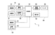
- FIG. 1 is a diagram showing a medical manipulator system (hereinafter simply referred to as “system”) 1 of the present embodiment.
- the medical manipulator 1 includes a first manipulator 50 that is introduced into the luminal organ To, and a second manipulator 10 that is introduced into the abdominal cavity Ac.
- the first manipulator 50 includes a long endoscope part 52 having an imaging part (first observation means) 51 and a treatment arm 55 attached to the distal end part of the endoscope part 52.
- the second manipulator 10 includes two arms, a treatment instrument arm 20 to which the treatment instrument 21 is attached and an observation arm 30 to which a laparoscope (second observation means) 31 is attached.
- the treatment instrument arm 20 and the observation arm 30 each have a plurality of joints.
- the treatment instrument 21 can be attached to and detached from the treatment instrument arm 20, and a plurality of treatment instruments can be appropriately exchanged and attached to the treatment instrument arm 20 in accordance with the content of the treatment.
- the laparoscope 31 has a known stereo optical system, and is configured to be able to measure the distance between an arbitrary position in front of the laparoscope 31 and the tip of the laparoscope.
- FIG. 2 is a functional block diagram of the system 1.
- the system 1 includes a main body 60 that is disposed outside a patient's body such as an operating room.
- the main body 60 includes a control unit 61 that controls the entire system 1, an operation unit 62 and an image processing unit 63 connected to the control unit 61, and a monitor (display unit) 65 connected to the image processing unit 63.
- the operation unit 62 generates an operation output based on the operator's operation input.
- the control unit 61 operates each joint of the first manipulator 50 and the second manipulator 10, the treatment instrument 21, the laparoscope 31, the imaging unit 51, the treatment arm 55, and the like based on the operation output received from the operation unit 62.
- the operation signal is generated.
- the controller 61 is connected to a drive source (not shown) such as a motor for driving the first manipulator 50 and the second manipulator 10 so as to be able to transmit and receive.
- the operation signal generated by the control unit 61 is transmitted to the drive source corresponding to the operation target. Thereby, the operation target is driven based on the operation signal, and each part of the first manipulator 50 and the second manipulator 10 operates based on the operation of the operator.
- the mode of the operation unit 62 can be set as appropriate.
- a plurality of input units respectively associated with the first manipulator 50 and the second manipulator 10 may be provided.
- the input unit may be associated with one of the first manipulator 50 and the second manipulator 10 and may be operated while appropriately switching the association.
- Video signals acquired by the laparoscope 31 and the imaging unit 51 are sent to the image processing unit 63.
- the image processing unit 63 generates a display image by known image processing using the acquired video signal, and displays it on the monitor 65.
- the operation at the time of use of the system 1 configured as described above will be described with reference to an example in the case where a lesion existing on the stomach wall (body wall) is treated.
- the surgeon determines the introduction positions of the treatment tool arm and the observation arm with respect to the patient, and forms a treatment tool and a port for introducing a laparoscope on the patient's abdominal wall.
- the treatment tool 21 is attached to the treatment tool arm 20, and the treatment tool arm 20 and the observation arm 30 are introduced into the abdominal cavity Ac (second side of the body wall) of the patient from the associated ports.
- the preparation for the second manipulator 10 is completed.
- the specific configuration of the treatment instrument 21 is appropriately selected according to the procedure to be performed.
- the treatment tool may be appropriately replaced during the procedure.
- the surgeon inserts the endoscope unit 52 of the first manipulator 50 through a natural opening such as the mouth of the patient, and while looking at the image of the imaging unit 51, the surgeon inserts the intragastric cavity (the body wall first).
- the tip of the first manipulator 50 is introduced to the vicinity of the target lesion on one side. Either the preparation of the second manipulator 10 or the introduction of the first manipulator 50 may be performed first. Or it may be performed in parallel by an assistant in addition to the surgeon.
- each joint of the second manipulator 10 in the coordinate system having a predetermined position set in the system as the origin, and the distal end portion of the endoscope unit 52 and the treatment arm 55 in the first manipulator 50.
- Each joint is known to the control unit 61.
- the positions of the distal end portions of the treatment instrument 21, the laparoscope 31, and the treatment arm 55 in the coordinate system are also known based on the dimensions of the respective portions. Therefore, at the start of use of the system 1, the control unit 61 includes the joints of the arms 20, 30, and 55 and the distal ends of the treatment instrument 21, the laparoscope 31, the endoscope unit 52, the treatment arm 55, and the like. Initial information regarding the position of the part is input.
- the above-described information (position information, etc.) relating to the position, posture, etc. of each part is updated as needed during the operation of the system 1.
- the update of information such as the position can be performed by a known technique. For example, an encoder or the like (not shown) is provided for each joint, and the control unit 61 receives information indicating the rotation angle from each joint every predetermined time. Then, based on the position information before update and the received information, the control unit 61 may calculate the position information after movement of each joint, and update the position information of each part. By updating the position information, the system 1 maintains a state in which the position information of each part is known to the control unit 61.
- the surgeon observes the target lesion using the first manipulator 50 and determines the excision range of the lesion. After the determination, the surgeon installs markings indicating the position of the target lesion, the resection range, and the like on the outer surface (second surface) of the stomach wall. This marking is a virtual marking that is not directly formed on the outer surface of the stomach but is superimposed on the stomach image displayed on the monitor 65.
- FIG. 3 is a flowchart showing the marking procedure described above.
- This marking procedure includes an operation method of the medical manipulator system in the present embodiment (hereinafter referred to as “operation method”).
- step S10 the operator places the distal end portion of the treatment arm 55 of the first manipulator 50 on the outer surface of the stomach wall where the marking is to be placed outside the stomach St (hereinafter, “installation site”).
- a part (hereinafter referred to as “corresponding part”) Cp on the stomach wall inner surface (first side face) inside the stomach St corresponding to Mp is brought into contact.
- the operator instructs the coordinate acquisition of the corresponding part Cp by a predetermined operation.
- step S20 the control unit 61 that has received the command acquires the coordinates of the distal end portion of the treatment arm 55 that is in contact with the corresponding site Cp.
- the control unit 61 acquires the acquired coordinates of the distal end portion of the treatment arm as the coordinates of the corresponding part Cp (corresponding part coordinate acquisition step).
- control unit 61 automatically drives the observation arm 30, and directs the laparoscope 31 to the coordinates of the corresponding part Cp acquired in step S20 as shown in FIG.
- the control unit 61 measures the distance to the stomach wall (object) located in front of the laparoscope 31 in a state where the laparoscope 31 faces the corresponding part Cp.
- step S40 the control unit 61 calculates the coordinates of the object located at the distance measurement point based on the distance measured in step S30 and the information such as the position of the observation arm 30, and the coordinates of the installation site Mp.
- the coordinates of the placement site Mp acquired by the control unit 61 are separated from the inside of the stomach St by the coordinate T of the corresponding site Cp designated by the operator and the thickness T of the stomach wall. The wall thickness is taken into consideration.
- step S50 the control unit 61 sends an instruction to the image processing unit 63 to control the image acquired by the laparoscope 31 at the coordinates of the installation site acquired in step S30 (marker display step).
- the marker M is displayed on the installation site Mp.
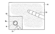
- FIG. 5 shows an example of an image displayed on the monitor 65.
- the display image has a main region R1 in which an image acquired by the imaging unit 51 is displayed and a sub-region R2 in which an image acquired by the laparoscope 31 is displayed.
- the marker M is displayed so as to be superimposed on the image outside the stomach on the installation site Mp in the image showing the outer surface of the stomach wall displayed in the sub-region R2.
- the main region R1 and the sub-region R2 may be configured such that the size relationship is reversed by an operator's operation, or the observation means corresponding to each may be switched by the operator's operation.
- the image processing unit 63 acquires feature point information indicating the feature point of the installation site Mp using the image acquired by the laparoscope 31, and stores the acquired feature point information (a feature point information acquisition step). ).
- the feature point information may be stored in a storage unit (not shown) provided in the main body unit 60, or may be stored in a storage medium externally attached to the main body unit 60.
- step S60 marking ends.
- the image processing unit 63 continues to specify the installation site Mp by image processing while updating the feature point information as needed. Thereby, in the image of the laparoscope 31 displayed on the monitor 65, the marker M is continuously superimposed and displayed on the specified installation site Mp.
- the procedure of FIG. 3 is repeated as necessary.
- the control unit 61 acquires the coordinates of the corresponding part Cp designated on one side of the luminal organ, and the corresponding part on the other side of the luminal organ. Based on the coordinates of the corresponding part Cp, the control unit 61 acquires the coordinates of the installation part Mp corresponding to Cp so that the wall thickness of the luminal organ is taken into consideration. Then, the marker M is superimposed and displayed at the coordinate position of the placement site Mp in the image on the other side of the hollow organ displayed on the monitor 65. Therefore, the marker M can be installed at the installation site accurately associated with the corresponding site without requiring a complicated operation such as the cooperative operation of the first manipulator 50 and the second manipulator 10.
- control part 61 can acquire the coordinate of the installation site
- the marker M is not directly formed on the luminal organ, the invasion of the patient does not increase even if the number of markers installed increases. Furthermore, it is possible to easily reposition the marker for the purpose of position correction or the like without giving a burden to the patient.
- the marker M is arranged on the image displayed on the monitor 65, it is possible to easily identify the plurality of markers by changing the color, shape, size, etc. of the plurality of markers by image processing. It is. Thereby, even when the laparoscope or the luminal organ moves after the marker is set, it is possible to accurately recognize the desired marker and perform the treatment accurately.
- step S60 the image processing unit 63 stores the feature point information of the installation site Mp, and then continues to track the installation site Mp while updating the feature point information. Therefore, even if the installation site Mp and its surrounding shape change due to the operator's operation or peristalsis, the marker M continues to be displayed on the installation site Mp. As a result, the state in which the control unit 61 grasps the installation site Mp is preferably maintained even during the treatment, and the surgeon can also continue to appropriately grasp the position of the installation site using the marker M.
- the coordinate acquisition command in step S10 can take various forms.
- a predetermined switch such as a foot switch provided in the operation unit is pressed
- a predetermined voice of the surgeon is acquired by voice recognition, and the like.
- the coordinate acquisition command is issued by the controller 61 when the high-frequency treatment instrument attached to the treatment arm 55 is turned on.
- the system 1 may be configured to be transmitted to
- step S50 and step S60 there is no restriction
- the coordinates of the installation site MP are acquired by the distance measuring function provided in the laparoscope 31 .
- a known motion is performed while the control unit moves the laparoscope.
- the coordinates of the installation site may be acquired by performing stereo distance measurement.
- the coordinates of the installation site may be acquired by TOF (Time Of Flight) ranging using a laser or ultrasonic wave, or SLAM (Simultaneous Localization and Mapping) using TOF ranging information,
- part may be acquired using techniques, such as Visual SLAM using the image which the laparoscope acquired.
- the tip of the treatment tool 21 is brought into contact with the information on the position of the installation site. Coordinates may be acquired. However, in this case, when the tip is brought into contact, an error may occur due to movement of the installation site. Therefore, as shown in FIG. It is preferable to carry out in a state where Cp is supported. If the step of acquiring the coordinates of the installation site is performed in a non-contact state with the luminal organ as described in the embodiment, the installation site is less likely to be displaced, and the coordinates can be acquired more accurately.
- the coordinate acquisition of the corresponding part may be performed in a non-contact manner with the luminal organ by stereo ranging or the like. Thereby, it is also possible to acquire coordinates in a non-contact state on both sides of the luminal organ.
- the corresponding site is located inside the hollow organ and the installation site is located outside the hollow organ, but it is natural that this may be reversed.
- the luminal organ to which the operating method of the present invention can be applied is not limited to the stomach, and can be suitably applied to other luminal organs such as the intestines.
- the operating method of the present invention can be suitably applied to marking on a body wall other than a luminal organ wall, such as a diaphragm.
- the present invention can be applied to a medical manipulator system.
Landscapes
- Health & Medical Sciences (AREA)
- Life Sciences & Earth Sciences (AREA)
- Surgery (AREA)
- Nuclear Medicine, Radiotherapy & Molecular Imaging (AREA)
- Biomedical Technology (AREA)
- Optics & Photonics (AREA)
- Pathology (AREA)
- Radiology & Medical Imaging (AREA)
- Biophysics (AREA)
- Engineering & Computer Science (AREA)
- Physics & Mathematics (AREA)
- Heart & Thoracic Surgery (AREA)
- Medical Informatics (AREA)
- Molecular Biology (AREA)
- Animal Behavior & Ethology (AREA)
- General Health & Medical Sciences (AREA)
- Public Health (AREA)
- Veterinary Medicine (AREA)
- Endoscopes (AREA)
Abstract
第一観察手段を備え、体壁の第一側に導入される第一マニピュレータと、第二観察手段を備え、体壁の第二側に導入される第二マニピュレータと、第一観察手段が取得した画像および第二観察手段が取得した画像に基づき表示画像を生成する画像処理部と、表示画像を表示する表示部と、第一マニピュレータおよび第二マニピュレータを駆動可能に構成され、かつ画像処理部を制御可能に構成された制御部と、を備える医療用マニピュレータシステムの作動方法は、制御部が、体壁の第一側の面上に位置する対応部位の座標を取得する対応部位座標取得工程と、制御部が、体壁の第二側の面上において、対応部位と対応する設置部位の座標を、体壁の壁厚を考慮するように取得する設置部位座標取得工程と、制御部が、表示画像のうち第二側の面が映る領域において、設置部位にマーカーが表示されるように画像処理部を制御するマーカー表示工程とを備える。
Description
本発明は、医療用マニピュレータシステムの作動方法に関する。
従来、観察手段および複数の処置具を体内に挿入した状態で術者が操作する医療用マニピュレータが知られている。
このような医療用マニピュレータを複数用いて、管腔臓器の内外でマニピュレータを操作することにより、処置を行うことが知られている。例えば、胃壁に存在する病変に対し、胃内に挿入したマニピュレータで病変を観察して切除線を決定し、腹腔に挿入したマニピュレータで切除線に沿って胃壁の一部を全層切除する。胃内に挿入したマニピュレータ単独では全層切除を行うことは困難であるが、胃の内外でマニピュレータを協働させることにより、開腹をせずに全層切除を行うことができ、患者の侵襲を低く抑えることができる。
このような医療用マニピュレータを複数用いて、管腔臓器の内外でマニピュレータを操作することにより、処置を行うことが知られている。例えば、胃壁に存在する病変に対し、胃内に挿入したマニピュレータで病変を観察して切除線を決定し、腹腔に挿入したマニピュレータで切除線に沿って胃壁の一部を全層切除する。胃内に挿入したマニピュレータ単独では全層切除を行うことは困難であるが、胃の内外でマニピュレータを協働させることにより、開腹をせずに全層切除を行うことができ、患者の侵襲を低く抑えることができる。
管腔臓器の内外でマニピュレータを協働操作する上述の処置では、一方で決定された切除線の位置が他方に正確に伝達されることが重要である。伝達が正確でないと、病変にメスが入ったり、不必要に広い範囲が切除されたりする可能性がある。
上記問題に関連して、特許文献1には、内視鏡の先端に磁石又はLEDを設け、磁石からの磁界またはLEDからの光を管腔臓器の外側から検出することにより、管腔臓器内の内視鏡の位置を検出することが記載されている。
特許文献1に記載の技術では、磁界や光が管腔臓器の壁を透過するため、管腔臓器の外側で十分に検出できない場合がある。その結果、内側で決定した情報が外側に正確に伝達されない可能性が残されている。
他の技術として、例えば高周波処置具等を用いた焼灼等により管腔臓器組織にマーキングを施すことが知られているが、臓器壁の一方に形成したマーキングは、通常他方側からは十分に視認できないため、同様の問題がある。他方から視認可能な程度にマーキングを行うと、患者の負担が増加する可能性がある。
さらに、管腔臓器は処置を行っている間も蠕動等により動くことがある。この場合、内側から伝達された位置を正確に把握し続けることは非常に困難である。
さらに、管腔臓器は処置を行っている間も蠕動等により動くことがある。この場合、内側から伝達された位置を正確に把握し続けることは非常に困難である。
上記事情を踏まえ、本発明は、管腔臓器の内外の一方から指定された位置を、使用者が正確に把握することができ、処置中も把握状態を維持することができる医療用マニピュレータシステムの作動方法を提供することを目的とする。
本発明は、第一観察手段を備え、体壁の第一側に導入される第一マニピュレータと、第二観察手段を備え、前記体壁の第二側に導入される第二マニピュレータと、前記第一観察手段が取得した画像および前記第二観察手段が取得した画像に基づき表示画像を生成する画像処理部と、前記表示画像を表示する表示部と、前記第一マニピュレータおよび前記第二マニピュレータを駆動可能に構成され、かつ前記画像処理部を制御可能に構成された制御部と、を備える医療用マニピュレータシステムの作動方法であって、前記制御部が、前記体壁の前記第一側の面上に位置する対応部位の座標を取得する対応部位座標取得工程と、前記制御部が、前記体壁の前記第二側の面上において、前記対応部位と対応する設置部位の座標を、前記体壁の壁厚を考慮するように取得する設置部位座標取得工程と、前記制御部が、前記表示画像のうち前記第二側の面が映る領域において、前記設置部位にマーカーが表示されるように前記画像処理部を制御するマーカー表示工程とを備える。
前記設置部位座標取得工程において、前記第二観察手段を前記対応部位の座標に向けた状態で、前記第二観察手段の前方の対象物との距離が測定されてもよい。
本発明の医療用マニピュレータシステムの作動方法は、前記画像処理部が、前記設置部位を含む画像から前記設置部位の特徴点情報を取得する特徴点情報取得工程を更に備えてもよい。
本発明の医療用マニピュレータシステムの作動方法によれば、管腔臓器の内外の一方から指定された位置を、使用者が正確に把握することができ、処置中も把握状態を維持することができる。
本発明の第一実施形態について、図1から図5を参照して説明する。
図1は、本実施形態の医療用マニピュレータシステム(以下、単に「システム」と称する。)1を示す図である。医療用マニピュレータ1は、管腔臓器To内に導入される第一マニピュレータ50と、腹腔Ac内に導入される第二マニピュレータ10とを備えている。
図1は、本実施形態の医療用マニピュレータシステム(以下、単に「システム」と称する。)1を示す図である。医療用マニピュレータ1は、管腔臓器To内に導入される第一マニピュレータ50と、腹腔Ac内に導入される第二マニピュレータ10とを備えている。
第一マニピュレータ50は、撮像部(第一観察手段)51を有する長尺の内視鏡部52と、内視鏡部52の先端部に取り付けられた処置アーム55とを備えている。
第二マニピュレータ10は、処置具21が取り付けられる処置具アーム20と、腹腔鏡(第二観察手段)31が取り付けられる観察アーム30との2つのアームを備えている。処置具アーム20および観察アーム30は、それぞれ複数の関節を有している。処置具21は、処置具アーム20に着脱可能であり、処置の内容等に応じて複数の処置具を適宜交換して処置具アーム20に装着することができる。腹腔鏡31は、公知のステレオ光学系を有し、腹腔鏡31の前方の任意の位置と腹腔鏡先端との距離を計測可能に構成されている。
第二マニピュレータ10は、処置具21が取り付けられる処置具アーム20と、腹腔鏡(第二観察手段)31が取り付けられる観察アーム30との2つのアームを備えている。処置具アーム20および観察アーム30は、それぞれ複数の関節を有している。処置具21は、処置具アーム20に着脱可能であり、処置の内容等に応じて複数の処置具を適宜交換して処置具アーム20に装着することができる。腹腔鏡31は、公知のステレオ光学系を有し、腹腔鏡31の前方の任意の位置と腹腔鏡先端との距離を計測可能に構成されている。
図2は、システム1の機能ブロック図である。システム1は、手術室内等の患者の体外に配置される本体部60を備える。本体部60は、システム1全体の制御を行う制御部61と、制御部61に接続された操作部62および画像処理部63と、画像処理部63と接続されたモニタ(表示部)65とを備える。
操作部62は、術者の操作入力に基づき操作出力を発生する。制御部61は、操作部62から受け取った操作出力に基づいて第一マニピュレータ50および第二マニピュレータ10の各関節や、処置具21、腹腔鏡31、撮像部51、処置アーム55等を動作させるための動作信号を生成する。
制御部61は、第一マニピュレータ50および第二マニピュレータ10の各部に駆動するためのモータ等の駆動源(不図示)と送受信可能に接続されている。制御部61で生成された動作信号は、動作対象に対応する駆動源に送信される。これにより、動作対象が動作信号に基づいて駆動され、第一マニピュレータ50および第二マニピュレータ10の各部が術者の操作に基づいて動作する。
操作部62は、術者の操作入力に基づき操作出力を発生する。制御部61は、操作部62から受け取った操作出力に基づいて第一マニピュレータ50および第二マニピュレータ10の各関節や、処置具21、腹腔鏡31、撮像部51、処置アーム55等を動作させるための動作信号を生成する。
制御部61は、第一マニピュレータ50および第二マニピュレータ10の各部に駆動するためのモータ等の駆動源(不図示)と送受信可能に接続されている。制御部61で生成された動作信号は、動作対象に対応する駆動源に送信される。これにより、動作対象が動作信号に基づいて駆動され、第一マニピュレータ50および第二マニピュレータ10の各部が術者の操作に基づいて動作する。
システム1において、操作部62の態様は適宜設定できる。たとえば、第一マニピュレータ50および第二マニピュレータ10にそれぞれ対応付けられた複数の入力部を備えてもよい。また、入力部が第一マニピュレータ50および第二マニピュレータ10の一方に対応付けられ、適宜対応付けを切り替えながら操作を行う態様であってもよい。
腹腔鏡31および撮像部51の取得した映像信号は、画像処理部63に送られる。画像処理部63は、取得した映像信号を用いて公知の画像処理等により表示用画像を生成し、モニタ65に表示する。
上記のように構成されたシステム1の使用時の動作について、胃壁(体壁)に存在する病変に処置を行う場合の例を用いて説明する。
術者は、患者に対する処置具アームおよび観察アームの導入位置を決定し、患者の腹壁に処置具および腹腔鏡導入用のポートを形成する。
次に、処置具アーム20に処置具21を取り付け、処置具アーム20および観察アーム30を、対応付けたポートから患者の腹腔Ac内(体壁の第二側)に導入する。以上で、第二マニピュレータ10の準備が完了する。
処置具21の具体的構成は、行う手技に応じて適宜選択される。手技中に処置具が適宜交換されてもよい。
術者は、患者に対する処置具アームおよび観察アームの導入位置を決定し、患者の腹壁に処置具および腹腔鏡導入用のポートを形成する。
次に、処置具アーム20に処置具21を取り付け、処置具アーム20および観察アーム30を、対応付けたポートから患者の腹腔Ac内(体壁の第二側)に導入する。以上で、第二マニピュレータ10の準備が完了する。
処置具21の具体的構成は、行う手技に応じて適宜選択される。手技中に処置具が適宜交換されてもよい。
次に、術者は、第一マニピュレータ50の内視鏡部52を患者の口等の自然開口から挿入し、撮像部51の映像を見ながら、管腔臓器である胃内(体壁の第一側)の対象病変の付近まで第一マニピュレータ50の先端部を導入する。
第二マニピュレータ10の準備と第一マニピュレータ50の導入とはどちらが先に行われてもよい。あるいは、術者の他に補助者が補助することにより、並行して行われてもよい。
第二マニピュレータ10の準備と第一マニピュレータ50の導入とはどちらが先に行われてもよい。あるいは、術者の他に補助者が補助することにより、並行して行われてもよい。
システム1では、システムに設定された所定位置を原点とする座標系における、第二マニピュレータ10の各関節の位置および姿勢、並びに第一マニピュレータ50における内視鏡部52の先端部および処置アーム55の各関節が、制御部61にとって既知となっている。さらに、処置具21、腹腔鏡31、および処置アーム55の先端部の座標系における位置も、各部の寸法等に基づき既知である。したがって、システム1の使用開始時において、制御部61には、各アーム20、30、および55の各関節、および処置具21、腹腔鏡31、内視鏡部52、及び処置アーム55等の先端部の位置等に関する初期情報が入力される。
上述した各部位の位置や姿勢等に関する情報(位置等情報)は、システム1の動作中、随時更新される。位置等情報の更新は、公知の技術により行うことができる。例えば、各関節に図示しないエンコーダ等を設け、制御部61が所定時間ごとに各関節から回転角度を示す情報を受信する。そして、更新前の位置等情報と受信した情報とに基づいて、制御部61が各関節の移動後の位置等情報を算出し、各部の位置等情報を更新すればよい。
位置等情報の更新により、システム1においては、各部位の位置等情報が制御部61に既知である状態が保持される。
位置等情報の更新により、システム1においては、各部位の位置等情報が制御部61に既知である状態が保持される。
術者は、第一マニピュレータ50を用いて対象病変を観察し、病変の切除範囲を決定する。決定後術者は、対象病変の位置や切除範囲等を示すマーキングを胃壁の外面(第二側の面)に設置する。このマーキングは、胃の外面上に直接形成されるのではなく、モニタ65に表示された胃の画像上に重畳表示される仮想マーキングである。
図3は、上述したマーキングの手順を示すフローチャートである。このマーキングの手順は、本実施形態における医療用マニピュレータシステムの作動方法(以下、「作動方法」と称する。)を含んでいる。
ステップS10において、術者は、図4に示すように、第一マニピュレータ50の処置アーム55の先端部を、胃Stの外側においてマーキングを設置したい胃壁外面上の位置(以下、「設置部位」)Mpに対応する、胃Stの内側における胃壁内面(第一側の面)上の部位(以下、「対応部位」)Cpに接触させる。処置アーム55の先端部が対応部位Cpに接触したことを確認したら、術者は所定の操作により対応部位Cpの座標取得を指令する。
続くステップS20において、指令を受信した制御部61は、対応部位Cpに接触している処置アーム55の先端部の座標を取得する。制御部61は、取得した処置アーム先端部の座標を対応部位Cpの座標として取得する(対応部位座標取得工程)。
次のステップS30において、制御部61は、観察アーム30を自動駆動し、図4に示すように、腹腔鏡31をステップS20で取得された対応部位Cpの座標に向ける。制御部61は、腹腔鏡31が対応部位Cpに向いた状態で、腹腔鏡31の前方に位置する胃壁(対象物)までの距離を測定する。
続くステップS40において、制御部61は、ステップS30で測定された距離と、観察アーム30の位置等情報とに基づいて、測距地点に位置する対象物の座標を算出し、設置部位Mpの座標として取得する(設置部位座標取得工程)。
図4に示すように、制御部61が取得した設置部位Mpの座標は、胃Stの内側から術者によって指定された対応部位Cpの座標と胃壁の厚さTだけ離れており、管腔臓器の壁厚が考慮された値となっている。
図4に示すように、制御部61が取得した設置部位Mpの座標は、胃Stの内側から術者によって指定された対応部位Cpの座標と胃壁の厚さTだけ離れており、管腔臓器の壁厚が考慮された値となっている。
ステップS50において制御部61は、腹腔鏡31の取得した画像に対し、ステップS30で取得した設置部位の座標にマーカーを表示するよう画像処理部63に指令を送って制御する(マーカー表示工程)。これにより、図5に示すように、モニタ65に表示される腹腔鏡の画像において、設置部位MpにマーカーMが表示される。
図5には、モニタ65に表示される画像の一例を示している。この例では、表示画像は、撮像部51が取得した画像が表示されるメイン領域R1と、腹腔鏡31が取得した画像が表示されるサブ領域R2とを有している。マーカーMは、サブ領域R2に表示された、胃壁の外面が映る画像における設置部位Mpに、胃の外側の画像と重畳するように表示されている。
メイン領域R1およびサブ領域R2は、面積の大小関係が術者の操作により逆転するよう構成されてもよいし、それぞれに対応する観察手段が術者の操作により切り替え可能に構成されてもよい。
図5には、モニタ65に表示される画像の一例を示している。この例では、表示画像は、撮像部51が取得した画像が表示されるメイン領域R1と、腹腔鏡31が取得した画像が表示されるサブ領域R2とを有している。マーカーMは、サブ領域R2に表示された、胃壁の外面が映る画像における設置部位Mpに、胃の外側の画像と重畳するように表示されている。
メイン領域R1およびサブ領域R2は、面積の大小関係が術者の操作により逆転するよう構成されてもよいし、それぞれに対応する観察手段が術者の操作により切り替え可能に構成されてもよい。
続くステップS60において、画像処理部63は、腹腔鏡31の取得した画像を用いて設置部位Mpの特徴点を示す特徴点情報を取得し、取得した特徴点情報を保存する(特徴点情報取得工程)。特徴点情報は、本体部60に設けられた図示しない記憶部に保存されてもよいし、本体部60に外付けされた記憶媒体等に保存されてもよい。
ステップS60が終了すると、マーキングが終了する。マーキング終了後、画像処理部63は、特徴点情報を随時更新しながら、画像処理により設置部位Mpを特定しつづける。これにより、モニタ65に表示される腹腔鏡31の画像において、特定された設置部位MpにマーカーMが継続して重畳表示される。
マーカーMを複数設置したい場合は、図3の手順を必要に応じて繰り返す。
マーカーMを複数設置したい場合は、図3の手順を必要に応じて繰り返す。
以上説明したように、本実施形態の作動方法によれば、管腔臓器の一方の側で指定された対応部位Cpの座標を制御部61が取得し、管腔臓器の他方の側において対応部位Cpと対応する設置部位Mpの座標を、制御部61が対応部位Cpの座標に基づいて、管腔臓器の壁厚が考慮されるように取得する。そして、モニタ65に表示される管腔臓器の他方側の画像における設置部位Mpの座標位置にマーカーMが重畳表示される。
したがって、第一マニピュレータ50と第二マニピュレータ10との協調動作のような煩雑な操作を必要とせずに、対応部位に対して正確に対応付けられた設置部位にマーカーMを設置することができる。
したがって、第一マニピュレータ50と第二マニピュレータ10との協調動作のような煩雑な操作を必要とせずに、対応部位に対して正確に対応付けられた設置部位にマーカーMを設置することができる。
また、制御部61は、取得した対応部位Cpの座標に基づいて設置部位Mpの座標を取得することができるため、術者は、対応部位の座標を指定する際に反対側から視認できる態様で行う必要がない。したがって、対応部位の指定時に、術者が患者に過剰な負担を与えることを防止することができる。
また、マーカーMが管腔臓器に直接形成されないため、マーカーの設置数が増加しても患者の侵襲は増加しない。さらに、位置修正等を目的とするマーカーの設置し直しも、患者に負担を与えずに容易に行うことが可能である。
さらに、マーカーMは、モニタ65に表示される画像上に配置されるため、画像処理により複数のマーカーの色や形、大きさ等を変えることで、複数のマーカーを識別容易にすることも可能である。これにより、マーカー設置後に腹腔鏡や管腔臓器が動いた場合でも、所望のマーカーを正確に認識して処置を的確に行うことができる。
加えて、ステップS60において、画像処理部63が、設置部位Mpの特徴点情報を保存し、その後特徴点情報を更新しながら設置部位Mpを追跡し続ける。したがって、術者の操作や蠕動等により設置部位Mpやその周囲の形状が変化しても、設置部位MpにマーカーMが表示され続ける。その結果、処置中も制御部61が設置部位Mpを把握した状態が好適に維持され、術者も、マーカーMにより設置部位の位置を好適に把握し続けることができる。
本実施形態において、ステップS10における座標取得指令は、様々な態様とすることができる。例えば、操作部に設けられたフットスイッチ等の所定のスイッチを押す、術者の所定の発声を音声認識により取得する、等が挙げられる。この他、術者による対応部位の指定を高周波処置具等による組織の部分焼灼で行う場合は、処置アーム55に取り付けられた高周波処置具の通電がオンとなることで座標取得指令が制御部61に送信されるようにシステム1が構成されてもよい。
また、図3のフローにおいて、ステップS50およびステップS60の順番には制限はない。したがって、図3とは逆の順番で行われてもよいし、並行して同時に行われてもよい。
さらに、上記の説明では、腹腔鏡31が備える測距機能により設置部位MPの座標の取得が行われる例を説明したが、これに代えて、制御部が、腹腔鏡を移動させながら公知のモーションステレオ測距を行うことにより設置部位の座標が取得されてもよい。
さらに、レーザーや超音波等を用いたTOF(Time Of Flight)方式の測距により設置部位の座標が取得されてもよいし、TOF方式の測距情報を用いたSLAM(Simultanious Localization and Mapping)、あるいは腹腔鏡の取得した画像を用いたVisual SLAM等の技術を用いて設置部位の座標が取得されてもよい。
さらに、レーザーや超音波等を用いたTOF(Time Of Flight)方式の測距により設置部位の座標が取得されてもよいし、TOF方式の測距情報を用いたSLAM(Simultanious Localization and Mapping)、あるいは腹腔鏡の取得した画像を用いたVisual SLAM等の技術を用いて設置部位の座標が取得されてもよい。
以上、本発明の一実施形態について説明したが、本発明の技術範囲は上記実施形態に限定されるものではなく、本発明の趣旨を逸脱しない範囲において構成要素の組み合わせを変えたり、各構成要素に種々の変更を加えたり、削除したりすることが可能である。
例えば、図6に示す変形例のように、設置部位Mpが存在する管腔臓器の他方側においても、処置具21の先端部を接触させることにより先端部の位置等情報を用いて設置部位の座標が取得されてもよい。
ただし、この場合、先端部を接触させる際に、設置部位が移動することにより誤差が生じる可能性があるため、図6に示すように、管腔臓器の反対側で処置アーム55等により対応部位Cpが支持された状態で行うのが好ましい。
設置部位の座標を取得する工程は、実施形態で説明したように管腔臓器と非接触状態で行うと、設置部位のずれが生じにくく、より正確に座標を取得することができる。
ただし、この場合、先端部を接触させる際に、設置部位が移動することにより誤差が生じる可能性があるため、図6に示すように、管腔臓器の反対側で処置アーム55等により対応部位Cpが支持された状態で行うのが好ましい。
設置部位の座標を取得する工程は、実施形態で説明したように管腔臓器と非接触状態で行うと、設置部位のずれが生じにくく、より正確に座標を取得することができる。
また、ステレオ測距等により、対応部位の座標取得が管腔臓器と非接触で行われてもよい。これにより、管腔臓器の両側において、非接触状態で座標取得を行うことも可能である。
さらに、上述の実施形態では、対応部位が管腔臓器の内側に、設置部位が管腔臓器の外側に位置する例を説明したが、これが逆の関係になってもよいことは当然である。
加えて、本発明の作動方法が適用できる管腔臓器は胃に限られず、腸等の他の管腔臓器にも好適に適用することができる。
さらに本発明の作動方法は、管腔臓器壁以外の体壁、たとえば横隔膜等にマーキングを行う場合にも好適に適用することができる。
加えて、本発明の作動方法が適用できる管腔臓器は胃に限られず、腸等の他の管腔臓器にも好適に適用することができる。
さらに本発明の作動方法は、管腔臓器壁以外の体壁、たとえば横隔膜等にマーキングを行う場合にも好適に適用することができる。
本発明は、医療用マニピュレータシステムに適用することができる。
1 医療用マニピュレータシステム
10 第二マニピュレータ
31 腹腔鏡(第二観察手段)
50 第一マニピュレータ
51 撮像部(第一観察手段)
61 制御部
63 画像処理部
65 モニタ(表示部)
Cp 対応部位
M マーカー
Mp 設置部位
10 第二マニピュレータ
31 腹腔鏡(第二観察手段)
50 第一マニピュレータ
51 撮像部(第一観察手段)
61 制御部
63 画像処理部
65 モニタ(表示部)
Cp 対応部位
M マーカー
Mp 設置部位
Claims (3)
- 第一観察手段を備え、体壁の第一側に導入される第一マニピュレータと、第二観察手段を備え、前記体壁の第二側に導入される第二マニピュレータと、前記第一観察手段が取得した画像および前記第二観察手段が取得した画像に基づき表示画像を生成する画像処理部と、前記表示画像を表示する表示部と、前記第一マニピュレータおよび前記第二マニピュレータを駆動可能に構成され、かつ前記画像処理部を制御可能に構成された制御部と、を備える医療用マニピュレータシステムの作動方法であって、
前記制御部が、前記体壁の前記第一側の面上に位置する対応部位の座標を取得する対応部位座標取得工程と、
前記制御部が、前記体壁の前記第二側の面上において、前記対応部位と対応する設置部位の座標を、前記体壁の壁厚を考慮するように取得する設置部位座標取得工程と、
前記制御部が、前記表示画像のうち前記第二側の面が映る領域において、前記設置部位にマーカーが表示されるように前記画像処理部を制御するマーカー表示工程と、
を備える、
医療用マニピュレータシステムの作動方法。 - 前記設置部位座標取得工程において、前記第二観察手段を前記対応部位の座標に向けた状態で、前記第二観察手段の前方の対象物との距離が測定される、請求項1に記載の医療用マニピュレータシステムの作動方法。
- 前記画像処理部が、前記設置部位を含む画像から前記設置部位の特徴点情報を取得する特徴点情報取得工程を更に備える、請求項1に記載の医療用マニピュレータシステムの作動方法。
Priority Applications (1)
| Application Number | Priority Date | Filing Date | Title |
|---|---|---|---|
| PCT/JP2015/085922 WO2017109874A1 (ja) | 2015-12-24 | 2015-12-24 | 医療用マニピュレータシステムの作動方法 |
Applications Claiming Priority (1)
| Application Number | Priority Date | Filing Date | Title |
|---|---|---|---|
| PCT/JP2015/085922 WO2017109874A1 (ja) | 2015-12-24 | 2015-12-24 | 医療用マニピュレータシステムの作動方法 |
Publications (1)
| Publication Number | Publication Date |
|---|---|
| WO2017109874A1 true WO2017109874A1 (ja) | 2017-06-29 |
Family
ID=59089701
Family Applications (1)
| Application Number | Title | Priority Date | Filing Date |
|---|---|---|---|
| PCT/JP2015/085922 Ceased WO2017109874A1 (ja) | 2015-12-24 | 2015-12-24 | 医療用マニピュレータシステムの作動方法 |
Country Status (1)
| Country | Link |
|---|---|
| WO (1) | WO2017109874A1 (ja) |
Citations (3)
| Publication number | Priority date | Publication date | Assignee | Title |
|---|---|---|---|---|
| JPH06285042A (ja) * | 1993-04-07 | 1994-10-11 | Olympus Optical Co Ltd | 体腔内位置検出システム |
| JP2002253480A (ja) * | 2001-03-02 | 2002-09-10 | Olympus Optical Co Ltd | 医療処置補助装置 |
| JP2003199707A (ja) * | 2001-12-28 | 2003-07-15 | Olympus Optical Co Ltd | 内視鏡装置 |
-
2015
- 2015-12-24 WO PCT/JP2015/085922 patent/WO2017109874A1/ja not_active Ceased
Patent Citations (3)
| Publication number | Priority date | Publication date | Assignee | Title |
|---|---|---|---|---|
| JPH06285042A (ja) * | 1993-04-07 | 1994-10-11 | Olympus Optical Co Ltd | 体腔内位置検出システム |
| JP2002253480A (ja) * | 2001-03-02 | 2002-09-10 | Olympus Optical Co Ltd | 医療処置補助装置 |
| JP2003199707A (ja) * | 2001-12-28 | 2003-07-15 | Olympus Optical Co Ltd | 内視鏡装置 |
Similar Documents
| Publication | Publication Date | Title |
|---|---|---|
| CN108433809B (zh) | 用于在手术过程期间设置并检索参考点的设备 | |
| KR102437404B1 (ko) | 수술 기구를 제어하는 시스템 및 방법 | |
| JP6311046B2 (ja) | ステープル又は血管シール器具におけるナイフ位置のインジケータ | |
| US10419680B2 (en) | Endoscope system and method of controlling endoscope system | |
| US20210345893A1 (en) | Indicator system | |
| JP2021118883A (ja) | 医療用アーム装置、医療用アーム装置の作動方法、及び情報処理装置 | |
| WO2019116592A1 (ja) | 内視鏡の表示画像の調整装置及び手術システム | |
| US20210369354A1 (en) | Navigational aid | |
| JP2023537882A (ja) | 管腔内ロボット(elr)システム及び方法 | |
| JP7755379B2 (ja) | 手術支援ロボットシステムおよび手術支援ロボットの制御方法 | |
| WO2020072360A1 (en) | Graphical user interface for defining an anatomical boundary | |
| JP2018506358A (ja) | ソフトウェア及び誘導管を備えたロボット制御の遠隔運動中心 | |
| US20200246105A1 (en) | Systems and methods for illumination of a patient anatomy in a teleoperational system | |
| US20200015910A1 (en) | Systems and methods for teleoperated control of an imaging instrument | |
| JP2015016181A (ja) | 手術支援ロボット | |
| JPWO2016136613A1 (ja) | マニピュレータシステム | |
| JP2006312079A (ja) | 医療用マニピュレータ | |
| WO2017109874A1 (ja) | 医療用マニピュレータシステムの作動方法 | |
| CN220175076U (zh) | 手持机器人辅助式内窥镜 | |
| US20250235287A1 (en) | Computer-assisted distance measurement in a surgical space | |
| US20260060514A1 (en) | Camera calibration for surgical systems | |
| CN114099006B (zh) | 一种器械与内窥镜距离提示方法 | |
| US20250318816A1 (en) | Systems and methods for arranging channels of an elongate flexible device | |
| WO2025212319A1 (en) | Computer-assisted annotation of subsurface structures onto a surface | |
| WO2025230837A1 (en) | Computer-assisted estimation of target overlay |
Legal Events
| Date | Code | Title | Description |
|---|---|---|---|
| 121 | Ep: the epo has been informed by wipo that ep was designated in this application |
Ref document number: 15911312 Country of ref document: EP Kind code of ref document: A1 |
|
| NENP | Non-entry into the national phase |
Ref country code: DE |
|
| 122 | Ep: pct application non-entry in european phase |
Ref document number: 15911312 Country of ref document: EP Kind code of ref document: A1 |
|
| NENP | Non-entry into the national phase |
Ref country code: JP |