WO2017109873A1 - マイクロインバータの盗難防止装置および太陽光発電システム - Google Patents
マイクロインバータの盗難防止装置および太陽光発電システム Download PDFInfo
- Publication number
- WO2017109873A1 WO2017109873A1 PCT/JP2015/085920 JP2015085920W WO2017109873A1 WO 2017109873 A1 WO2017109873 A1 WO 2017109873A1 JP 2015085920 W JP2015085920 W JP 2015085920W WO 2017109873 A1 WO2017109873 A1 WO 2017109873A1
- Authority
- WO
- WIPO (PCT)
- Prior art keywords
- alarm
- micro inverter
- solar cell
- cell module
- micro
- Prior art date
- Legal status (The legal status is an assumption and is not a legal conclusion. Google has not performed a legal analysis and makes no representation as to the accuracy of the status listed.)
- Ceased
Links
Images




Classifications
-
- H—ELECTRICITY
- H02—GENERATION; CONVERSION OR DISTRIBUTION OF ELECTRIC POWER
- H02M—APPARATUS FOR CONVERSION BETWEEN AC AND AC, BETWEEN AC AND DC, OR BETWEEN DC AND DC, AND FOR USE WITH MAINS OR SIMILAR POWER SUPPLY SYSTEMS; CONVERSION OF DC OR AC INPUT POWER INTO SURGE OUTPUT POWER; CONTROL OR REGULATION THEREOF
- H02M7/00—Conversion of AC power input into DC power output; Conversion of DC power input into AC power output
- H02M7/42—Conversion of DC power input into AC power output without possibility of reversal
- H02M7/44—Conversion of DC power input into AC power output without possibility of reversal by static converters
- H02M7/48—Conversion of DC power input into AC power output without possibility of reversal by static converters using discharge tubes with control electrode or semiconductor devices with control electrode
Definitions
- Embodiments of the present invention relate to a micro inverter theft prevention device and a photovoltaic power generation system including the micro inverter.
- the micro inverter is a small power conditioner attached to the back side of each solar cell module or a frame.
- micro inverter is installed for each solar cell module. Therefore, in the solar cell module in which the micro inverter is installed, individual maximum power tracking control (MPPT: Maximum power point tracker) and DC / AC power conversion can be performed for each module unit. Therefore, even if the function of each solar cell module deteriorates due to the influence of the utility pole or the shadow of the electric wire, there is no concern that the influence will affect the power generation amount of the entire photovoltaic power generation system.
- MPPT Maximum power point tracker
- a conventional power conditioner connects 10 to 15 solar cell modules per unit and performs power conversion in a batch. Yes.
- Such a conventional power conditioner has a certain amount of weight and a large apparatus itself.
- the micro inverter since the micro inverter is only large enough to fit on the back side of the solar cell module, it is lightweight and requires a small installation space. Therefore, the solar cell module provided with the micro inverter has good space properties and is suitable for installation in a densely populated area in an urban area.
- the solar cell module provided with the micro inverter can be easily installed even from one sheet, it can be freely arranged. Therefore, it is excellent in the freedom of arrangement design and workability.
- a solar cell module can be mounted in a desired layout on a narrow roof such as a covered parking lot pouch or a covered bus waiting area, a small veranda, a garden, or an eaves.
- the solar cell module uses a micro inverter, so that the degree of freedom of installation is increased, and it is possible to select a place with high power generation efficiency by avoiding a shadowed part of a utility pole or electric wire.
- the installation location of the solar cell module can be expanded and optimized, and the efficiency of the photovoltaic power generation system is further improved.
- the solar cell module provided with the micro inverter is suitable for installation in a densely populated area. Therefore, the risk of the micro inverter being stolen is much higher than that of a conventional power conditioner.
- micro inverter If the micro inverter is stolen, not only the device itself is physically lost, but also the amount of power generated for one solar cell module is lost. Therefore, conventionally, in a solar cell module provided with a micro inverter, it is urgent to prevent the micro inverter from being stolen.
- Embodiment of this invention is proposed in order to eliminate the above subject.
- An object of an embodiment of the present invention is to provide a micro inverter theft prevention device and a photovoltaic power generation system that can prevent theft.
- an embodiment of the present invention is an antitheft device for a micro inverter connected to a solar cell module and a system, and issues an alarm when the solar cell module or system is disconnected.
- An alarm unit is provided.
- a solar power generation system including the anti-theft device for the micro inverter is also one embodiment.
- FIG. 1 shows the surface of the solar cell module 1 on the light receiving surface side
- the lower part of FIG. 1 shows the back surface of the solar cell module 1 on the opposite side.
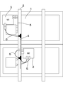
- the solar cell module 1 includes 6 ⁇ 11 solar cells, and a rectangular panel is formed as a whole. As shown in FIGS. 2 and 3, the back surfaces of the two solar cell modules 1 are fixed to the gantry 2.
- the solar cell module 1 is supported by the gantry 2, and the solar cell module 1 is arranged by attaching the gantry 2 to the roof of a house.
- the microinverter 3 is installed on the back side of the solar cell module 1.
- the micro inverter 3 is directly attached and fixed directly to the corner of the back surface of the solar cell module 1.
- the solar cell module 1 to which the micro inverter 3 is integrally attached is called an AC module.
- the micro inverter 3 is attached to the gantry 2 instead of the back surface of the solar cell module 1.
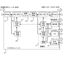
- FIG. 4 is a control block of the micro inverter 3.
- the microinverter 3 includes input and output filters 31 and 36 for noise removal, a DC / DC converter 32, an insulating transformer 33, a rectifier circuit 34, a DC / AC converter 35, and the like. The components for power conversion are provided.
- the micro inverter 3 includes a control circuit 37 for controlling the DC / DC converter 32 and a control circuit 38 for controlling the DC / AC converter 35, and a power supply circuit 39 for supplying power to the control circuits 37 and 38, 40 is provided.
- the micro inverter 3 having these components creates an output current command value based on the voltage phase of the system. Moreover, the micro inverter 3 changes the amplitude of an output current according to the output of the solar cell module 1, and adjusts the electric power supplied to the system side by this. For this reason, the microinverter 3 incorporates a protection device and the like necessary for grid connection.
- connection configuration between the solar cell module 1 side and the system side and the micro inverter 3 will be described with reference to FIGS.
- the output side of the solar cell module 1 and the input side of the micro inverter 3 are connected by a DC cable 5.
- strain side is attached to the mount frame 2 (illustrated in FIG. 3).
- the microinverter 3 is connected to the system side through the connection portion 4.
- the output side of the micro inverter 3 and the connection part 4 to the system side are connected by an AC cable 6.
- the DC cable 5 and the AC cable 6 serve as connectors, and the solar cell module 1 is connected to the system via the micro inverter 3 and the connection portion 4.
- the present embodiment is an antitheft device for the micro inverter 3 and is incorporated in the micro inverter 3. As shown in FIGS. 4 to 6, the antitheft device for the micro inverter 3 according to the present embodiment is provided with an alarm unit 7 for generating an alarm inside the micro inverter 3.
- the alarm unit 7 is provided with a speaker 8 as an audio output unit, an LED 9 as a light emitting unit, and further a communication unit 10 as parts that issue an alarm.
- the speaker 8, LED 9, and communication unit 10 are controlled by the control circuit 38.
- a power supply circuit 40 is connected to the control circuit 38.
- Speaker 8 outputs an alarm sound or a sound such as “Micro Inverter No ** is disconnected” as an alarm.
- “No **” is a serial number assigned to the micro inverter 3.
- LED9 lights up or blinks as a state which issues an alarm.
- the communication unit 10 transmits an alarm signal to a remote monitoring monitor 12 (shown in FIG. 6) incorporated in the remote monitoring device (gateway).
- the remote monitoring monitor 12 When the remote monitoring monitor 12 receives an alarm signal from the communication unit 10, the remote monitoring monitor 12 displays a message such as “Micro inverter No ** is disconnected” (see FIG. 6). “No **” displayed on the remote monitoring monitor 12 corresponds to the serial number assigned to the micro inverter 3.
- a communication method of the communication unit 10 for example, a wireless 920 MHz band is used.
- the alarm unit 7 issues a predetermined alarm from the speaker 8, the LED 9, and the communication unit 10.
- the state where the DC cable 5 and the AC cable 6 are allowed to be disconnected is established, for example, by inputting an alarm release signal to the control circuit 38 of the micro inverter 3 in advance.
- the control circuit 38 is configured to lock various alarms.
- the state in which the DC cable 5 and the AC cable 6 are removed means that the microinverter 3 is electrically disconnected from the solar cell module 1 or the connection part 4 to the system side.
- the input / output unit is open. That is, the state where the input part of the micro inverter 3 is open is a state where the DC cable 5 is disconnected from the solar cell module 1 or the micro inverter 3 or the DC cable 5 is cut.
- the state in which the output part of the micro inverter 3 is open is a state in which the AC cable 6 is disconnected from the micro inverter 3 or the connection part 4 to the system side, or the AC cable 6 is disconnected.
- the control circuit 38 of the alarm unit 7 is connected to the power source 11 (shown in FIG. 4) via the power circuit 40. ). Thereby, the alarm unit 7 can issue an alarm even if the power supply is cut off.
- the anti-theft device for the micro inverter 3 includes an alarm unit 7 that receives an electric power supply from the power source 11 and issues an alarm when the micro inverter 3 is disconnected.
- the alarm by the alarm unit 7 is an alarm signal from the communication unit 10 such as an alarm sound from the speaker 8, such as an alarm sound from the LED 9.
- the alarm unit 7 issues an alarm such as an alarm sound, it is possible to notify the surroundings of the microinverter 3 and to prevent theft.
- an alarm from the alarm unit 7 can easily reach the vicinity and is effective as a countermeasure against theft.
- the remote monitoring monitor 12 when the remote monitoring monitor 12 receives an alarm signal from the communication unit 10, a display such as “Micro inverter No ** is disconnected” is output. Therefore, the monitoring person watching the remote monitoring monitor 12 can immediately confirm that the theft of the micro inverter 3 has occurred, and can quickly deal with it.
- the micro inverter 3 by preventing the micro inverter 3 from being stolen, the micro inverter 3 itself is not lost, and the power generation amount of the solar cell module 1 is not lost. As a result, the risk of economic loss can be eliminated, which can contribute to the promotion of the introduction of a photovoltaic power generation system using the micro inverter 3.
- the alarm unit 7 lights or blinks the LED 9. At this time, even if it is nighttime, if the solar cell module 1 generates power by the light of the LED 9, the probability that the micro inverter 3 is stolen is high.
- the remote monitoring monitor 12 incorporated in the remote monitoring device detects the power generation of the solar cell module 1 at night, it can be determined that the micro inverter 3 is stolen. For this reason, even if the communication unit 10 breaks down and the alarm signal cannot be transmitted to the remote monitoring monitor 12, it is possible to grasp the theft of the micro inverter 3 by monitoring the solar cell module 1 by the remote monitoring monitor 12. Is possible.
- the alarm unit 7 may be provided with an accelerometer or the like so as to issue an alarm when the micro inverter 3 is moved from a predetermined mounting position.
- the alarm unit 7 is not built in the micro inverter 3 but may be a separate external member. In that case, when the alarm unit 7 is removed from a predetermined mounting position, an alarm may be issued. .
- the mounting position of the alarm unit 7 can be selected as appropriate, such as the solar cell module 1 itself, the gantry 2, or the DC cable 5 or the AC cable 6.
- the power supply 11 of the alarm unit 7 may be a secondary battery such as a nickel cadmium battery or a primary battery such as a lithium battery.
- the power source 11 of the alarm unit 7 is incorporated in the micro inverter 3 itself. Instead, the alarm unit 7 is provided as the power source 11 of the alarm unit 7. You may make it utilize the output from the micro inverter 3 different from the micro inverter 3. FIG.
- the micro-inverter 3 on the unremoved side is used as the power source 11 of the alarm unit 7 on the micro-inverter 3 side previously removed.
- the output of it is not necessary to incorporate a battery or the like into the micro inverter 3 as the power source 11, and the alarm unit 7 can continue to issue an alarm using the output from another micro inverter 3.
- the communication unit 10 not only transmits an alarm signal, but also receives an alarm signal, and transmits an alarm signal transmitted by the communication unit 10 of the adjacent micro inverter 3 to another communication unit of another micro inverter 3. If 10 receives, you may make it the alarm part 7 of this micro inverter 3 emit a warning.
- the power source 11 such as a battery
- the alarm unit 7 of the micro inverter 3 other than the micro inverter 3 that is likely to be stolen may issue an alarm. it can. Therefore, even if the solar cell module 1 side and the system side are both disconnected, it is possible to reliably issue an alarm from an unexpected place as seen by the thief, and to enhance the anti-theft effect. is there.
- the alarm unit 7 is installed for each micro inverter 3, and each alarm unit 7 uses the output of the micro inverter 3 different from the micro inverter 3 provided with the alarm unit 7. However, at this time, a different type of alarm may be issued for each alarm unit 7 of each micro inverter 3.
- the alarm unit 7 of the micro inverter 3 sounds an alarm sound with a pattern “A” when the micro inverter 3 itself is disconnected, and the communication unit 10 receives an alarm signal from another micro inverter 3. In this case, an alarm sound is generated with a pattern “B” different from the pattern “A”.
- the alarm unit 7 of the micro inverter 3 if the alarm unit 7 of the micro inverter 3 is sounding the alarm sound of the pattern “A”, it informs the surroundings whether the micro inverter 3 itself is about to be stolen. Can do. Further, if the alarm unit 7 of the micro inverter 3 is sounding the alarm sound of the pattern “B”, it is possible to inform the surroundings that the micro inverter 3 other than the micro inverter 3 has been stolen. In this way, the difference in the theft situation can be notified to the surroundings by the difference in the alarm sound, and the person who manages the micro inverter 3 can quickly take measures according to the situation.
- the some micro inverter 3 may be connected to a gateway apparatus. At this time, if any of the micro inverters 3 is detected as being disconnected from the solar cell module 1 or the system or both in the gateway device, the alarm unit 7 of the micro inverter 3 different from the removed micro inverter 3 is detected. An unconnected state detection signal may be output. And the alarm part 7 which received the non-connection state detection signal outputs an alarm.
- the gateway device places a plurality of micro inverters 3 under monitoring and is stolen. An alarm for notifying that the alarm unit 7 of the micro inverter 3 other than 3 has been stolen can be issued. Thereby, it is possible to obtain an excellent anti-theft effect.
- the gateway device monitors the plurality of micro inverters 3.
- the alarm form of the alarm unit 7 may be different for each micro inverter 3. According to these embodiments, it is possible to accurately grasp which micro inverter 3 is stolen from the difference in the form of alarm. Therefore, even when the micro inverter 3 is installed in a wide range, it is possible to quickly take an effective corresponding measure.
- the anti-theft object by the anti-theft device may be extended to devices attached to each solar cell module 1.
- a DCDC optimizer that controls the output of the solar cell module 1 to a constant voltage
- a solar cell module monitoring unit that monitors the power generation state of the solar cell module may be targeted for theft prevention.
- the solar cell module monitoring unit include a monitor slave unit provided for each solar cell module 1. The monitor slave unit measures the voltage of each solar cell module 1 and sends the measured data to the monitor master unit.
- the alarm unit 7 issues an alarm. Therefore, it is possible to prevent not only the micro inverter 3 but also the DCDC optimizer and the solar cell module monitoring unit from being stolen.
- a power line communication method may be adopted.
- the data monitoring is detected by the remote monitoring monitor 12 on the data receiving side and the remote monitoring is performed.
- an alarm that data transfer is interrupted may be displayed.
- the technology for detecting the non-connected state of the micro inverter 3 with respect to the solar cell module 1 or the like is not limited to the detection of the electrical non-connected state, and the micro inverter 3 is physically removed. You may make it detect a state. For example, the presence or absence of an electric wire connecting the micro inverter 3 and the outside may be detected using an optical sensor or the like.
- the shape and material of the connector can be selected as appropriate.
- the connector such as the DC cable 5 or the AC cable 6
- an attachment portion attached to the solar cell module side or system side, and the solar cell module side or system side A connecting portion that is electrically connected to each other may be provided independently.
- the alarm part 7 is good also as what issues a warning when the attachment part of a connector is removed from the solar cell module 1 side or the system
- the alarm unit 7 since the alarm unit 7 operates quickly, the anti-theft effect can be further enhanced.
- the communication unit 10 may transmit not only the alarm signal to the remote monitoring device but also the information regarding the solar cell module 1 acquired by the micro inverter 3 to the remote monitoring device.
- the communication unit 10 may receive a command from an operation terminal such as an administrator or a user from the remote monitoring device.
- the remote monitoring monitor 12 is not incorporated in the remote monitoring device (gateway) of the solar power generation system, and may be provided independently.
Landscapes
- Engineering & Computer Science (AREA)
- Power Engineering (AREA)
- Inverter Devices (AREA)
- Burglar Alarm Systems (AREA)
Abstract
盗難を防止することができるマイクロインバータの盗難防止装置および太陽光発電システムを提供する。マイクロインバータ3には、マイクロインバータ3の盗難防止装置として警報部7が内蔵される。警報部7は、マイクロインバータ3の入出力部がオープンな状態になると、警報を発する。警報部7には、音声出力部であるスピーカ8、発光部であるLED9、警報信号を遠隔監視モニタ12へと送信する通信部10が設置されている。
Description
本発明の実施形態は、マイクロインバータの盗難防止装置およびマイクロインバータを含む太陽光発電システムに関する。
近年、太陽光発電システムの実用化が進み、太陽電池モジュールは高い需要を得ている。中でも、太陽電池モジュール1枚に1つのマイクロインバータを備えたものが注目を集めている。マイクロインバータとは、各太陽電池モジュールの裏側または架台などに取り付けられた、小型のパワーコンディショナである。
マイクロインバータは、太陽電池モジュール毎に1台設置されている。そのため、マイクロインバータを設置した太陽電池モジュールでは、各モジュール単位で、個々の最大電力追従制御(MPPT:Maximum power point Tracker)およびDC/AC電力変換を行うことができる。したがって、電柱や電線の影などの影響を受けて各太陽電池モジュールの機能が低下したとしても、その影響が太陽光発電システム全体の発電量に及ぶ心配がない。
マイクロインバータが太陽電池モジュール1枚毎に設置されるのに対して、従来型のパワーコンディショナは、1台あたり太陽電池モジュール10枚~15枚を接続して、一括して電力変換を行っている。このような従来型のパワーコンディショナは、ある程度の重量があり、装置自体も大きい。
一方、マイクロインバータは、太陽電池モジュールの裏面側に十分に収まるほどの大きさしかないので、軽量で、設置スペースも狭くて済む。したがって、マイクロインバータを備えた太陽電池モジュールは、スペース性が良好であり、都市部の住宅密集エリアなどへの設置に適している。
また、マイクロインバータを備えた太陽電池モジュールは、1枚からでも簡単に設置することができるので、自由な配列が可能である。したがって、配置設計の自由度および施工性に優れている。例えば、屋根付きの駐車場ポーチや屋根付きのバス待合所などの狭小な屋根、小さなベランダや庭、軒先などに、好みのレイアウトで太陽電池モジュールを取り付つけることができる。
このように、太陽電池モジュールは、マイクロインバータを用いたことで、設置の自由度が上がりで、電柱や電線の影となる部分を避けて発電効率の高い場所を選ぶこともできる。その結果、太陽電池モジュールの設置場所の拡張および最適化が実現し、太陽光発電システムの効率がより向上するというメリットがある。
従来型のパワーコンディショナは、ある程度の重量があるため、屋内あるいは屋外の壁などに強固に固定されている。そのため、従来型のパワーコンディショナは、持ち運びや取外しが難しく、盗まれるリスクは低い。これに対して、マイクロインバータは小型で軽量なので、持ち運びおよび取り外しが簡単である。したがって、マイクロインバータは盗難に遭う可能性が大きいと言える。
特に、野立てや陸屋根設置された太陽電池モジュールでは、各太陽電池モジュールや架台に設置されたマイクロインバータまで、簡単に手が届いてしまう。その上、先に述べたように、マイクロインバータを備えた太陽電池モジュールは住宅密集エリアへの設置に適している。したがって、マイクロインバータが盗難に遭うリスクは、従来型のパワーコンディショナに比べて格段に高くなっている。
マイクロインバータが盗まれると、機器自体が物理的に失われるだけでなく、太陽電池モジュール1枚分の発電量も失われることになる。そこで従来から、マイクロインバータを備えた太陽電池モジュールにおいては、マイクロインバータの盗難防止が急務となっていた。
本発明の実施形態は、以上の課題を解消するために提案されたものである。本発明の実施形態の目的は、盗難を防止することができるマイクロインバータの盗難防止装置および太陽光発電システムを提供することにある。
上記の目的を達成するために、本発明の実施形態は、太陽電池モジュールおよび系統に接続されたマイクロインバータの盗難防止装置であって、太陽電池モジュールもしくは系統と非接続状態になると、警報を発する警報部を備えている。また、上記マイクロインバータの盗難防止装置を含む太陽光発電システムも、実施態様の一つである。
[第1の実施形態]
[構成の概要]
本発明の第1の実施形態について、図面を参照して説明する。図1の上段は受光面側である太陽電池モジュール1の表面、図1の下段は反対側の太陽電池モジュール1の裏面を示している。
[構成の概要]
本発明の第1の実施形態について、図面を参照して説明する。図1の上段は受光面側である太陽電池モジュール1の表面、図1の下段は反対側の太陽電池モジュール1の裏面を示している。
図1に示すように、太陽電池モジュール1は、6×11枚の太陽電池セルが配置されており、全体として矩形パネルが形成されている。図2および図3に示すように、2枚の太陽電池モジュール1の裏面が架台2に固定されている。この架台2によって太陽電池モジュール1が支えられ、家屋の屋根などに架台2が取り付けられることで太陽電池モジュール1が配置される。
図1の下段および図3に示すように、マイクロインバータ3は、太陽電池モジュール1の裏面側に設置されている。図3の上側の太陽電池モジュール1では、マイクロインバータ3は太陽電池モジュール1の裏面の隅に直接、一体的に取り付けられ、固定されている。マイクロインバータ3が一体的に取り付けられた太陽電池モジュール1は、ACモジュールと呼ばれている。また、図3の下側に示した太陽電池モジュール1では、マイクロインバータ3は、太陽電池モジュール1の裏面ではなく、架台2に取り付けられている。
図4は、マイクロインバータ3の制御ブロックである。図4に示すように、マイクロインバータ3には、ノイズ除去用の入力側および出力側のフィルタ31および36、DC/DC変換器32、絶縁トランス33、整流回路34及びDC/AC変換器35等の電力変換用の構成要素が設けられている。また、マイクロインバータ3には、DC/DC変換器32を制御する制御回路37およびDC/AC変換器35を制御する制御回路38と、これら制御回路37および38に電力を供給する電源回路39、40が設けられている。
これらの構成要素を持つマイクロインバータ3は、系統の電圧位相を基準にして出力電流指令値を作成する。また、マイクロインバータ3は、太陽電池モジュール1の出力に合わせて出力電流の振幅を変更し、これにより、系統側に供給する電力を調整する。そのため、マイクロインバータ3には系統連系に必要となる保護装置なども組み込まれている。
図3および図5を用いて、太陽電池モジュール1側および系統側と、マイクロインバータ3との接続構成について説明する。図3および図5の(B)に示すように、太陽電池モジュール1の出力側とマイクロインバータ3の入力側とは、DCケーブル5によって接続されている。また、系統側への接続部4が架台2に取り付けられている(図3に図示)。この接続部4を介してマイクロインバータ3が系統側に接続されている。マイクロインバータ3の出力側と系統側への接続部4とは、ACケーブル6によって接続されている。以上のように、DCケーブル5およびACケーブル6がコネクタとなり、マイクロインバータ3および接続部4を介して、太陽電池モジュール1が系統に接続される。
[マイクロインバータの盗難防止装置の構成]
本実施形態は、マイクロインバータ3の盗難防止装置であって、マイクロインバータ3の内部に組み込まれている。図4~図6に示すように、本実施形態に係るマイクロインバータ3の盗難防止装置には、マイクロインバータ3の内部に、警報を発する警報部7が設けられている。
本実施形態は、マイクロインバータ3の盗難防止装置であって、マイクロインバータ3の内部に組み込まれている。図4~図6に示すように、本実施形態に係るマイクロインバータ3の盗難防止装置には、マイクロインバータ3の内部に、警報を発する警報部7が設けられている。
図4および図6に示すように、警報部7には、警報を発する部分として、音声出力部であるスピーカ8、発光部であるLED9、さらには通信部10が設置されている。図4に示すように、これらスピーカ8、LED9、通信部10は、制御回路38によって制御される。制御回路38には電源回路40が接続されている。
スピーカ8は、警報として、アラーム音あるいは「マイクロインバータNo**が外れています」といった音声を出力する。ここで「No**」とは、マイクロインバータ3に当てられた通し番号とする。LED9は、警報を発する状態として点灯あるいは点滅する。通信部10は、遠隔監視装置(ゲートウェイ)に組み込まれた遠隔監視モニタ12(図6に図示)へと警報信号を送信する。
遠隔監視モニタ12は、通信部10から警報信号を受信すると「マイクロインバータNo**が外れています」といった表示を行う(図6参照)。遠隔監視モニタ12に表示される「No**」は、マイクロインバータ3にふり当てられた通し番号に対応する。なお、通信部10の通信方式としては、例えば無線の920MHz帯を使用する。
警報部7は、予め定められた許容状態以外でDCケーブル5およびACケーブル6が外されると、上記のスピーカ8、LED9、通信部10が所定の警報を発する。DCケーブル5およびACケーブル6を外すことを許容する状態とは、例えば、マイクロインバータ3の制御回路38へ予め警報解除信号が入力されることなどで成立する。具体的には制御回路38が警報解除信号を入力している場合、制御回路38は各種警報の発報をロックするようになっている。
DCケーブル5およびACケーブル6を外した状態とは、マイクロインバータ3が太陽電池モジュール1もしくは系統側への接続部4と電気的に非接続状態になることであり、このとき、マイクロインバータ3の入出力部はオープンな状態になる。すなわち、マイクロインバータ3の入力部がオープンな状態とは、DCケーブル5が太陽電池モジュール1あるいはマイクロインバータ3から外される、もしくはDCケーブル5が切断された状態である。
また、マイクロインバータ3の出力部がオープンな状態とは、ACケーブル6がマイクロインバータ3あるいは系統側への接続部4から外される、もしくはACケーブル6が切断された状態である。このような状態で、マイクロインバータ3が太陽電池モジュール1側もしくは系統側と電気的に非接続状態になると、警報部7の制御回路38は、電源回路40を介して電源11(図4に図示)から電力を供給される。これにより、警報部7は、電力供給が断たれても警報の発報が可能となっている。
[作用と効果]
本実施形態に係るマイクロインバータ3の盗難防止装置は、マイクロインバータ3が非接続状態になると、電源11からの電力供給を受けて警報を発する警報部7を備えている。警報部7による警報とは、スピーカ8からのアラーム音など、LED9の点灯または点滅、通信部10からの警報信号である。
本実施形態に係るマイクロインバータ3の盗難防止装置は、マイクロインバータ3が非接続状態になると、電源11からの電力供給を受けて警報を発する警報部7を備えている。警報部7による警報とは、スピーカ8からのアラーム音など、LED9の点灯または点滅、通信部10からの警報信号である。
このような本実施形態では、警報部7がアラーム音などの警報を発することで、マイクロインバータ3の盗難を周囲に知らせることができ、盗難を抑止することができる。特に、マイクロインバータ3を備えた太陽電池モジュール1は、住宅密集エリアに設置されることが多いので、警報部7からの警報が近隣に届き易く、盗難の抑止対策として有効である。
また、本実施形態では、遠隔監視モニタ12により、通信部10から警報信号を受信すると、「マイクロインバータNo**が外れています」といった表示が出力する。したがって、遠隔監視モニタ12を見ている監視員がマイクロインバータ3の盗難が発生したことが即座に確認することができ、迅速な対処が可能となる。
以上のような本実施形態によれば、マイクロインバータ3の盗難を防止することで、マイクロインバータ3自体を失わないことは勿論のこと、太陽電池モジュール1の発電量が失われることもない。これにより、経済的な損失というリスクを排除することができ、マイクロインバータ3を用いた太陽光発電システムの導入促進に寄与することができる。
また、仮にマイクロインバータ3の盗難が夜間に発生して、警報部7がLED9を点灯又は点滅させるとする。このとき、夜間であるにもかかわらず、LED9の光により太陽電池モジュール1が発電したのであれば、マイクロインバータ3の盗難が発生している確率が高いことになる。
そこで、遠隔監視装置(ゲートウェイ)に組み込まれた遠隔監視モニタ12が夜間に太陽電池モジュール1の発電を検知した場合には、マイクロインバータ3の盗難が起きていると判断することができる。このため、万が一、通信部10が故障して警報信号を遠隔監視モニタ12に送信できなくなったとしても、遠隔監視モニタ12による太陽電池モジュール1の監視によって、マイクロインバータ3の盗難を把握することが可能である。
[他の実施形態]
本発明のいくつかの実施形態を説明したが、これらの実施形態は、例として提示したものであり、発明の範囲を限定することは意図していない。これら実施形態は、その他の様々な形態で実施されることが可能であり、発明の要旨を逸脱しない範囲で、種々の省略、置き換え、変更を行うことができる。これら実施形態やその変形は、発明の範囲や要旨に含まれると同様に、請求の範囲に記載された発明とその均等の範囲に含まれるものである。
本発明のいくつかの実施形態を説明したが、これらの実施形態は、例として提示したものであり、発明の範囲を限定することは意図していない。これら実施形態は、その他の様々な形態で実施されることが可能であり、発明の要旨を逸脱しない範囲で、種々の省略、置き換え、変更を行うことができる。これら実施形態やその変形は、発明の範囲や要旨に含まれると同様に、請求の範囲に記載された発明とその均等の範囲に含まれるものである。
(A)警報部7は、加速度計などを設けて、マイクロインバータ3が所定の取付位置から動かされると、警報を発するようにしてもよい。警報部7はマイクロインバータ3に内蔵するのではなく、外付けの別部材であってもよく、その場合、警報部7が所定の取付位置から外されると、警報を発するようにしてもよい。警報部7の取付位置は、太陽電池モジュール1自体、架台2、あるいはDCケーブル5やACケーブル6など、適宜選択自由である。また、警報部7の電源11としては、ニッカド電池などの二次電池やリチウム電池などの一次電池などでよい。
(B1)上記の第1の実施形態では、マイクロインバータ3自体に警報部7の電源11を組み込む構成としたが、これに代えて、警報部7の電源11として、その警報部7を備えたマイクロインバータ3とは異なるマイクロインバータ3からの出力を、利用するようにしてもよい。
例えば、近接した2台のマイクロインバータ3が全く同時に取り外されることはないと想定して、先に取り外されたマイクロインバータ3側の警報部7の電源11として、取り外されていない側のマイクロインバータ3の出力を利用するようにする。この実施形態によれば、電源11として電池などをマイクロインバータ3に組み込む必要がなく、別のマイクロインバータ3からの出力を利用して、警報部7は警報を発報し続けることができる。
また、通信部10は、警報信号を送信するだけではなく、警報信号を受信できるようにしておき、隣接したマイクロインバータ3の通信部10が送信した警報信号を、別のマイクロインバータ3の通信部10が受信すると、このマイクロインバータ3の警報部7が警報を発するようにしてもよい。
以上の実施形態では、太陽電池モジュール1側および系統側つまりDC側とAC側の両方で非接続状態となり、警報部7が電源を失って警報信号が送信されなくなるといった事態を想定している。この場合、あるマイクロインバータ3の通信部10が警報信号を送信して別のマイクロインバータ3の通信部10が受信すれば、警報信号を受信した通信部10を持つ警報部7が動作を開始して、警報を発することができる。
この実施形態によれば、電池などの電源11をマイクロインバータ3に組み込む必要がない。しかも、これらの構成では、マイクロインバータ3を有する太陽電池モジュール1が複数集まって用いられる場合に、盗まれそうになったマイクロインバータ3以外のマイクロインバータ3の警報部7が、警報を発することができる。したがって、太陽電池モジュール1側および系統側の両方で非接続状態となったとしても、窃盗犯から見て予想外の場所から警報を確実に出すことができ、盗難抑止効果を高めることが可能である。
(B2)上記の実施形態では、マイクロインバータ3毎に警報部7を設置し、各警報部7は、この警報部7を備えたマイクロインバータ3とは異なるマイクロインバータ3の出力を用いることになるが、このとき、各マイクロインバータ3の警報部7毎に異なる形態の警報を発するようにしてもよい。
例えば、マイクロインバータ3の警報部7は、マイクロインバータ3自身が非接続状態となった場合にはパターン「A」で警報音を鳴らし、通信部10が別のマイクロインバータ3から警報信号を受信した場合には、パターン「A」とは異なるパターン「B」で警報音を鳴らすようにする。
このような実施形態によれば、マイクロインバータ3の警報部7がパターン「A」の警報音を鳴らしていれば、そのマイクロインバータ3自身がまさに盗まれそうになっているのかを周囲に知らせることができる。また、マイクロインバータ3の警報部7がパターン「B」の警報音を鳴らしていれば、マイクロインバータ3とは別のマイクロインバータ3が盗まれたという状況を周囲に知らせることができる。このように、警報音の相違により盗難の状況の違いを周囲に知らせることができ、マイクロインバータ3を管理する者は、状況に応じた対処を迅速に取ることが可能である。
(B3)また、複数のマイクロインバータ3をゲートウェイ装置に接続することがある。このとき、ゲートウェイ装置において、マイクロインバータ3のいずれかが太陽電池モジュール1または系統あるいは両方から外れたことを検知すると、外されたマイクロインバータ3とは別のマイクロインバータ3の警報部7に対して非接続状態検知信号を出力するようにしてもよい。そして、非接続状態検知信号を受けた警報部7が警報を出力する。
この実施形態によれば、マイクロインバータ3が太陽電池モジュール1側および系統側の両方で非接続状態となったとしても、ゲートウェイ装置が複数のマイクロインバータ3を監視下に置き、盗まれたマイクロインバータ3以外のマイクロインバータ3の警報部7の盗難が発生したことを知らせる警報を発することができる。これにより、優れた盗難抑止効果を獲得することが可能である。
(B4)また、ゲートウェイ装置自体に警報を発する警報部7を設けるようにしてもよい。上記の実施形態では、ゲートウェイ装置が複数のマイクロインバータ3を監視することになるが、このとき、警報部7の警報の形態を、マイクロインバータ3毎に異ならせるにしてもよい。これらの実施形態によれば、警報の形態の違いから、どのマイクロインバータ3が盗まれているのかを的確に把握することができる。したがって、マイクロインバータ3が広い範囲に設置されている場合でも、有効な対応した対処を素早くに取ることが可能である。
(C)盗難防止装置による盗難防止対象を、太陽電池モジュール1毎に取り付けられている機器にまで広げてもよい。例えば、太陽電池モジュール1の出力を一定の電圧に制御するDCDCオプティマイザーや、太陽電池モジュールの発電状態を監視する太陽電池モジュール監視部を盗難防止対象としてもよい。太陽電池モジュール監視部としては、例えば太陽電池モジュール1毎に設けられるモニタ子機などがある。モニタ子機とは、各太陽電池モジュール1の電圧などを測定して、測定したデータをモニタ親機に送るものである。
これらの実施形態では、DCDCオプティマイザーや太陽電池モジュール監視部が太陽電池モジュール1から外されて非接続状態になると、警報部7が警報を発するようになっている。したがって、マイクロインバータ3だけではなく、DCDCオプティマイザーや太陽電池モジュール監視部の盗難も防止することが可能になる。
(D)警報部7における通信部10の通信方式としては、電力線通信方式を採用してもよい。この場合、マイクロインバータ3の盗難により、例えばACケーブル6が取り外されると、データ搬送が途絶するので、このデータ搬送の途絶を、データ受信側である遠隔監視モニタ12などで把握して、遠隔監視モニタ12側で、データ搬送が途切れているという警報を表示するようにしてもよい。
(E)警報部7において、太陽電池モジュール1などに対するマイクロインバータ3の非接続状態を検知する技術としては、電気的な非接続状態の検知に限らず、マイクロインバータ3が物理的に取り外された状態を検知するようにしてもよい。例えば、マイクロインバータ3と外部とを繋ぐ電線の有無を、光学センサなどを用いて検知するようにしてもよい。
また、コネクタの形状や材質などは適宜選択可能であり、例えば、DCケーブル5やACケーブル6などのコネクタに関して、太陽電池モジュール側または系統側に取り付けられる取付部と、太陽電池モジュール側または系統側に電気的に接続される接続部とを独立して設けるようにしてもよい。そして、警報部7は、コネクタの電気的な接続部が非接続状態となる前に、太陽電池モジュール1側もしくは系統側からコネクタの取付部が外された時点で、警報を発するものとしてもよい。このような実施形態では、警報部7が迅速に動作するので、盗難防止効果をより高めることができる。
(F)警報部7における音声出力部、発光部および通信部の構成や設置数などは適宜変更可能であり、スピーカ8からのアラーム音や音声出力の種類、さらにはLED9の点滅パターンなども適宜選択可能である。
(G)通信部10は、警報信号を遠隔監視装置に送信するだけではなく、マイクロインバータ3が取得した太陽電池モジュール1に関する情報も、遠隔監視装置へ送信するようにしてもよい。また、通信部10は、管理者あるいはユーザなどの操作端末からの指令を遠隔監視装置から受信するようにしてもよい。
(H)遠隔監視モニタ12は、太陽光発電システムの遠隔監視装置(ゲートウェイ)に組み込まれるものではなく、これとは別に独立して設けるようにしてもよい。
1…太陽電池モジュール
2…架台
3…マイクロインバータ
4…系統側への接続部
6…ACケーブル
5…DCケーブル
7…警報部
8…スピーカ
9…LED
10…通信部
11…電源
12…遠隔監視モニタ
31、36…フィルタ
32…DC/DC変換器
33…絶縁トランス
34…整流回路
35…DC/AC変換器
37、38…制御回路
39、40…電源回路
2…架台
3…マイクロインバータ
4…系統側への接続部
6…ACケーブル
5…DCケーブル
7…警報部
8…スピーカ
9…LED
10…通信部
11…電源
12…遠隔監視モニタ
31、36…フィルタ
32…DC/DC変換器
33…絶縁トランス
34…整流回路
35…DC/AC変換器
37、38…制御回路
39、40…電源回路
Claims (13)
- 太陽電池モジュールおよび系統に接続されたマイクロインバータの盗難防止装置であって、
太陽電池モジュールもしくは系統と非接続状態になると、警報を発する警報部を備えたことを特徴とするマイクロインバータの盗難防止装置。 - 前記警報部は、音声出力部、発光部および通信部のうち、少なくとも1つを有することを特徴とする請求項1に記載のマイクロインバータの盗難防止装置。
- マイクロインバータの入出力部がオープンな状態になると前記警報部に電力を供給する電源を備えたことを特徴とする請求項1または2に記載のマイクロインバータの盗難防止装置。
- 前記マイクロインバータ毎に前記警報部を設置し、
前記警報部の電源として、当該警報部を設置したマイクロインバータとは異なるマイクロインバータの出力を用いることを特徴とする請求項1~3のいずれかに記載のマイクロインバータの盗難防止装置。 - 前記警報部は、当該警報部を備えたマイクロインバータとは異なるマイクロインバータの出力を用いるとき、当該警報部を設置した前記マイクロインバータが太陽電池モジュールもしくは系統と非接続状態になった時に発する警報とは異なる形態で、警報を発することを特徴とする請求項4に記載のマイクロインバータの盗難防止装置。
- 複数のマイクロインバータを接続するゲートウェイ装置を設け、
前記マイクロインバータ毎に前記警報部を設置し、
前記ゲートウェイ装置は、前記マイクロインバータのうちのいずれかが太陽電池モジュールおよび系統の少なくとも一方から外れたことを検知すると、外されたマイクロインバータとは別のマイクロインバータに設置された前記警報部に対して非接続状態検知信号を出力し、
前記非接続状態検知信号を受けた前記警報部が警報を出力することを特徴とする請求項1~5のいずれかに記載のマイクロインバータの盗難防止装置。 - 前記検知信号を受けた前記警報部は、当該警報部を設置した前記マイクロインバータが太陽電池モジュールもしくは系統と非接続状態になった時に発する警報とは異なる形態で、警報を発することを特徴とする請求項6に記載のマイクロインバータの盗難防止装置。
- 複数のマイクロインバータを接続するゲートウェイ装置を設け、
前記ゲートウェイ装置には、前記マイクロインバータのうちのいずれかが太陽電池モジュールおよび系統の少なくとも一方から外れると、警報を発する警報部を設けたことを特徴とする請求項1~7のいずれかに記載のマイクロインバータの盗難防止装置。 - 前記ゲートウェイ装置に設けた前記警報部は、前記マイクロインバータ毎に異なる形態で警報を発することを特徴とする請求項8に記載のマイクロインバータの盗難防止装置。
- マイクロインバータが太陽電池モジュールもしくは系統とコネクタを介して取り付けられており、
前記警報部は、当該コネクタが外されると警報を発することを特徴とする請求項1~9のいずれかに記載のマイクロインバータの盗難防止装置。 - 請求項1~10のいずれかに記載のマイクロインバータの盗難防止装置を有する太陽電池モジュールと、
前記警報部からの警報を監視する監視装置を備えたことを特徴とする太陽光発電システム。 - 前記各太陽電池モジュールにはDCDCオプティマイザーを接続し、
前記警報部は、前記太陽電池モジュールと前記DCDCオプティマイザーが非接続状態になると警報を発することを特徴とする請求項11に記載の太陽光発電システム。 - 前記各太陽電池モジュールには当該太陽電池モジュールを監視する太陽電池モジュール監視部を接続し、
前記警報部は、前記太陽電池モジュールと前記太陽電池モジュール監視部が非接続状態になると警報を発することを特徴とする請求項11または12に記載の太陽光発電システム。
Priority Applications (1)
| Application Number | Priority Date | Filing Date | Title |
|---|---|---|---|
| PCT/JP2015/085920 WO2017109873A1 (ja) | 2015-12-24 | 2015-12-24 | マイクロインバータの盗難防止装置および太陽光発電システム |
Applications Claiming Priority (1)
| Application Number | Priority Date | Filing Date | Title |
|---|---|---|---|
| PCT/JP2015/085920 WO2017109873A1 (ja) | 2015-12-24 | 2015-12-24 | マイクロインバータの盗難防止装置および太陽光発電システム |
Publications (1)
| Publication Number | Publication Date |
|---|---|
| WO2017109873A1 true WO2017109873A1 (ja) | 2017-06-29 |
Family
ID=59090971
Family Applications (1)
| Application Number | Title | Priority Date | Filing Date |
|---|---|---|---|
| PCT/JP2015/085920 Ceased WO2017109873A1 (ja) | 2015-12-24 | 2015-12-24 | マイクロインバータの盗難防止装置および太陽光発電システム |
Country Status (1)
| Country | Link |
|---|---|
| WO (1) | WO2017109873A1 (ja) |
Citations (6)
| Publication number | Priority date | Publication date | Assignee | Title |
|---|---|---|---|---|
| JPH06259668A (ja) * | 1993-03-04 | 1994-09-16 | Komesu Kk | 侵入検知装置 |
| JP2002099969A (ja) * | 2000-09-22 | 2002-04-05 | Iwata Electric:Kk | ピッキング警報装置 |
| JP2002142462A (ja) * | 2000-10-30 | 2002-05-17 | Canon Inc | 電力変換装置およびその盗難防止方法 |
| JP2003337983A (ja) * | 2002-05-21 | 2003-11-28 | Iiyama Corp | 警報システム、端末警報装置および警報受信装置 |
| JP2012256184A (ja) * | 2011-06-08 | 2012-12-27 | Hitachi Cable Ltd | 太陽電池モジュールの盗難監視装置及びこれを用いた盗難監視システム |
| JP2015517291A (ja) * | 2012-03-30 | 2015-06-18 | サンパワー コーポレイション | ヒートシンク付き電子的構成要素ハウジング |
-
2015
- 2015-12-24 WO PCT/JP2015/085920 patent/WO2017109873A1/ja not_active Ceased
Patent Citations (6)
| Publication number | Priority date | Publication date | Assignee | Title |
|---|---|---|---|---|
| JPH06259668A (ja) * | 1993-03-04 | 1994-09-16 | Komesu Kk | 侵入検知装置 |
| JP2002099969A (ja) * | 2000-09-22 | 2002-04-05 | Iwata Electric:Kk | ピッキング警報装置 |
| JP2002142462A (ja) * | 2000-10-30 | 2002-05-17 | Canon Inc | 電力変換装置およびその盗難防止方法 |
| JP2003337983A (ja) * | 2002-05-21 | 2003-11-28 | Iiyama Corp | 警報システム、端末警報装置および警報受信装置 |
| JP2012256184A (ja) * | 2011-06-08 | 2012-12-27 | Hitachi Cable Ltd | 太陽電池モジュールの盗難監視装置及びこれを用いた盗難監視システム |
| JP2015517291A (ja) * | 2012-03-30 | 2015-06-18 | サンパワー コーポレイション | ヒートシンク付き電子的構成要素ハウジング |
Similar Documents
| Publication | Publication Date | Title |
|---|---|---|
| US8749395B2 (en) | Method and apparatus for indicating a disconnection within a distributed generator | |
| US8466789B2 (en) | Method for theft recognition on a photovoltaic unit and inverter for a photovoltaic unit | |
| US20130328404A1 (en) | Voltage conversion apparatus, power generation system, and voltage conversion method | |
| JP2006216660A (ja) | 太陽光発電装置および接続制御装置 | |
| US20140021792A1 (en) | Solar power system and communication apparatus | |
| CN103267889A (zh) | 一种新型的智能光伏汇流装置 | |
| WO2017109873A1 (ja) | マイクロインバータの盗難防止装置および太陽光発電システム | |
| JP2013081290A (ja) | 配電システム | |
| KR101589877B1 (ko) | 광대역 통신망을 이용한 태양광 모니터링 시스템 | |
| KR101049786B1 (ko) | 태양광발전장치의 통합관리시스템 | |
| CN217882390U (zh) | 一种适用于高压储能系统的汇流柜 | |
| JP2009303426A (ja) | 発電システム | |
| CN202838580U (zh) | 一种火灾自动报警控制系统 | |
| CN210321718U (zh) | 一种杆塔倾斜度检测系统 | |
| JP2012049233A (ja) | 太陽光発電パネル又は太陽電池アレイ | |
| CN101635472B (zh) | 无线通讯系统及照明系统 | |
| CN205643735U (zh) | 一种光伏离网系统 | |
| CN208092896U (zh) | 一种人防户内型音视一体化警报控制器 | |
| CN216595367U (zh) | 一种电网严重配网故障多阶段预警系统 | |
| KR20160044410A (ko) | 태양광 발전시스템에서 접속유닛의 화재진압 방법 | |
| CN204377184U (zh) | 一种led供电电路 | |
| GB2532999A (en) | Integrated long range ISM sub gigahertz network for monitoring & controlling theft, damage and loss of supply to high voltage cables | |
| CN218918206U (zh) | 一种光伏电站线缆防盗预警装置 | |
| CN209981137U (zh) | 一种跳闸报警装置 | |
| CN203325913U (zh) | 逆变器 |
Legal Events
| Date | Code | Title | Description |
|---|---|---|---|
| 121 | Ep: the epo has been informed by wipo that ep was designated in this application |
Ref document number: 15911311 Country of ref document: EP Kind code of ref document: A1 |
|
| NENP | Non-entry into the national phase |
Ref country code: DE |
|
| 122 | Ep: pct application non-entry in european phase |
Ref document number: 15911311 Country of ref document: EP Kind code of ref document: A1 |
|
| NENP | Non-entry into the national phase |
Ref country code: JP |