WO2017104813A1 - 複合粒子及びその製造方法 - Google Patents
複合粒子及びその製造方法 Download PDFInfo
- Publication number
- WO2017104813A1 WO2017104813A1 PCT/JP2016/087581 JP2016087581W WO2017104813A1 WO 2017104813 A1 WO2017104813 A1 WO 2017104813A1 JP 2016087581 W JP2016087581 W JP 2016087581W WO 2017104813 A1 WO2017104813 A1 WO 2017104813A1
- Authority
- WO
- WIPO (PCT)
- Prior art keywords
- hydrogen
- particles
- hydrogen detection
- composite particles
- detection member
- Prior art date
- Legal status (The legal status is an assumption and is not a legal conclusion. Google has not performed a legal analysis and makes no representation as to the accuracy of the status listed.)
- Ceased
Links
Images




Classifications
-
- G—PHYSICS
- G01—MEASURING; TESTING
- G01N—INVESTIGATING OR ANALYSING MATERIALS BY DETERMINING THEIR CHEMICAL OR PHYSICAL PROPERTIES
- G01N21/00—Investigating or analysing materials by the use of optical means, i.e. using sub-millimetre waves, infrared, visible or ultraviolet light
- G01N21/75—Systems in which material is subjected to a chemical reaction, the progress or the result of the reaction being investigated
-
- G—PHYSICS
- G01—MEASURING; TESTING
- G01N—INVESTIGATING OR ANALYSING MATERIALS BY DETERMINING THEIR CHEMICAL OR PHYSICAL PROPERTIES
- G01N21/00—Investigating or analysing materials by the use of optical means, i.e. using sub-millimetre waves, infrared, visible or ultraviolet light
- G01N21/75—Systems in which material is subjected to a chemical reaction, the progress or the result of the reaction being investigated
- G01N21/77—Systems in which material is subjected to a chemical reaction, the progress or the result of the reaction being investigated by observing the effect on a chemical indicator
-
- G—PHYSICS
- G01—MEASURING; TESTING
- G01N—INVESTIGATING OR ANALYSING MATERIALS BY DETERMINING THEIR CHEMICAL OR PHYSICAL PROPERTIES
- G01N21/00—Investigating or analysing materials by the use of optical means, i.e. using sub-millimetre waves, infrared, visible or ultraviolet light
- G01N21/75—Systems in which material is subjected to a chemical reaction, the progress or the result of the reaction being investigated
- G01N21/77—Systems in which material is subjected to a chemical reaction, the progress or the result of the reaction being investigated by observing the effect on a chemical indicator
- G01N21/78—Systems in which material is subjected to a chemical reaction, the progress or the result of the reaction being investigated by observing the effect on a chemical indicator producing a change of colour
-
- G—PHYSICS
- G01—MEASURING; TESTING
- G01N—INVESTIGATING OR ANALYSING MATERIALS BY DETERMINING THEIR CHEMICAL OR PHYSICAL PROPERTIES
- G01N31/00—Investigating or analysing non-biological materials by the use of the chemical methods specified in the subgroup; Apparatus specially adapted for such methods
Definitions
- the present invention relates to composite particles, a method for producing composite particles, a hydrogen detection member, a hydrogen detection method, and a method for processing a hydrogen detection member.
- a hydrogen detection member In order to detect hydrogen, a hydrogen detection member is used as an indispensable element.
- a hydrogen detection member As a hydrogen detection member, a hydrogen sensor that detects hydrogen by a change in electrical resistance of the surface of a semiconductor (tin oxide) due to adsorption of hydrogen is often used.
- the operating temperature is about 400 ° C. and heating is required.
- Patent Document 1 discloses an element having a stacked structure of a metal that adsorbs and dissociates hydrogen or a hydrogen-containing compound gas and a solid compound that is reduced by hydrogen atoms in the metal, and changes in light absorption of the solid compound due to reduction.
- a gas sensor comprising optical means for detection is disclosed.
- Patent Document 2 discloses a hydrogen sensor in which a catalyst layer is formed in contact with a magnesium thin film having a thickness of 40 nm or less.
- Patent Document 3 on the substrate, are a thickness of 10 ⁇ 200 nm magnesium-palladium alloy MgPd x (0.05 ⁇ x ⁇ 0.3 ) thin film is formed, on the substrate, or A hydrogen sensor in which a catalyst layer is further formed on a thin film is disclosed.
- One embodiment of the present invention provides composite particles capable of detecting hydrogen in a short time by visual observation and maintaining the state in which hydrogen is detected even when temporarily exposed to an atmosphere containing hydrogen. With the goal.
- nanopalladium particles are attached to the surface of nickel oxyhydroxide particles in a composite particle, and the molar ratio of Pd to Ni is 0.01 to 0.03.
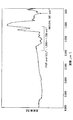
- FIG. 2 is an FT-IR spectrum of the composite particles of Example 1.
- 2 is an X-ray photoelectron spectroscopy spectrum around Ni 2p of the composite particle of Example 1.
- FIG. 2 is an X-ray photoelectron spectroscopy spectrum around Pd 3d of the composite particles of Example 1.
- FIG. 2 is an X-ray diffraction spectrum of a composite particle of Example 1.
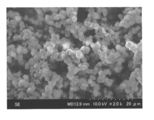
- FIG. 2 is a scanning electron micrograph (2000 times) of the composite particles of Example 1.
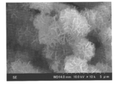
- FIG. 2 is a scanning electron micrograph (10,000 times) of the composite particles of Example 1.
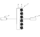
- FIG. FIG. 3 is a schematic view showing an optical device for measuring the light transmittance of the hydrogen detection member of Example 1. It is a figure which shows the measurement result of the light transmittance of the hydrogen detection member of Example 1.
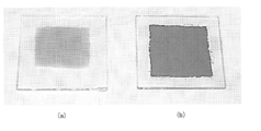
- FIG. It is the photograph before and behind detecting the hydrogen of the hydrogen detection member of Example 1.
- nanopalladium particles are attached to the surface of the nickel oxyhydroxide particles.
- the molar ratio of Pd to Ni in the composite particles is 0.01 to 0.03, preferably 0.15 to 0.025.
- hydrogen cannot be detected in a short time by visual observation, and when it exceeds 0.03, hydrogen cannot be detected by visual observation.
- the composite particles When the composite particles are exposed to an atmosphere containing hydrogen, nickel oxyhydroxide is reduced to nickel hydroxide by the catalytic action of nanopalladium particles adhering to the surface of the composite particles, and the wavelength ranges from 400 to 800 nm. Thus, the light transmittance or reflectance changes.
- the nickel oxyhydroxide particles are black.
- the particle diameter of the nickel oxyhydroxide particles is preferably 2 to 5 ⁇ m.
- the method for synthesizing the nickel oxyhydroxide particles is not particularly limited, and examples thereof include a chemical bath deposition method, a coprecipitation method, and a uniform precipitation method.
- Nickel oxyhydroxide particles can be synthesized by dropping an aqueous solution of a metal compound containing, an aqueous solution of potassium persulfate, and an aqueous solution of ammonium hydroxide.
- a sufficient amount of an aqueous solution of an alkali metal hydroxide is preferably added appropriately.
- the catalytic properties of nanopalladium particles are dramatically improved compared to normal palladium particles due to the increase in surface area accompanying the nanosize of the particle size.
- the number average particle diameter of the nanopalladium particles is preferably 20 to 40 nm.
- the nanopalladium particles preferably have a protective layer formed on the surface.
- the protective layer preferably contains a water-soluble polymer.
- the water-soluble polymer is not particularly limited, and examples thereof include polyvinyl pyrrolidone and polyol.
- the method for synthesizing the nanopalladium particles is not particularly limited, and examples thereof include a chemical reduction method and a solution method.
- reaction solution for example, in a reaction vessel at 70 ° C., an aqueous solution of a metal compound containing palladium as a main component, a water-soluble polymer as a material constituting the protective layer, and an aqueous solution of sodium hydroxide (NaOH) are reacted. By doing so, nanopalladium particles can be synthesized. At that time, the reaction solution is preferably made alkaline.
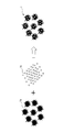
- FIG. 1 shows an example of a method for producing composite particles of the present embodiment.
- the composite particles 1 can be produced by mixing the nickel oxyhydroxide particles 1a and the nanopalladium particles 1b in a solvent.
- the solvent is not particularly limited, and examples thereof include water and ethanol. Among these, water is particularly preferable.
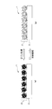
- FIG. 2 shows an example of the hydrogen detection member of this embodiment.
- the hydrogen detection member detects hydrogen by a change in optical properties, and a hydrogen detection film 2 including the composite particles 1 is formed on the substrate 3.
- the hydrogen detection film 2 changes in light transmittance or reflectance according to an atmosphere containing hydrogen to be exposed.
- the film thickness of the hydrogen detection film 2 is preferably 20 to 100 ⁇ m.
- the thickness of the hydrogen detection film 2 is 20 ⁇ m or more, the black color of the hydrogen detection film 2 is easily recognized by visual observation.
- the thickness is 100 ⁇ m or less, the white color of the hydrogen detection film 2 is easily recognized by visual observation.
- the hydrogen detection film 2 can be formed by a wet coating method.
- the wet coating method is not particularly limited, and examples thereof include a spin coating method, a spray coating method, a dip coating method, and a drop coating method.
- the hydrogen detection film 2 can be formed by a wet coating method, the hydrogen detection film 2 having a large surface area can also be formed at high speed. Further, since an expensive vacuum device or the like is not used, the hydrogen detection member of the present embodiment can be manufactured at a very low cost compared to the conventional hydrogen detection member.
- the material constituting the substrate 3 is not particularly limited, but is an oxide such as glass, quartz, sapphire, and lithium niobate, polymer such as polyethylene terephthalate (PET), and cellophane tape that transmits light in the visible light region. Examples thereof include metals and opaque plastics that reflect light in the visible light region.
- FIG. 3 shows an example of the hydrogen detection method of the present embodiment.
- the hydrogen detection film 2 is black in a state before detecting hydrogen (see FIG. 3A), but changes to white when hydrogen is detected by exposure to an atmosphere containing hydrogen (FIG. 3B). )reference). Therefore, the hydrogen detection member of the present embodiment has a greater contrast before and after hydrogen detection than the conventional hydrogen detection member, so that even when a small amount of hydrogen is contained in the atmosphere, hydrogen can be detected visually. .
- the hydrogen detection film 2 has a memory property that retains white color once it is detected and changes to white color. Therefore, even when hydrogen leakage has occurred in the past and then no longer occurs, hydrogen leakage can be visually confirmed. For this reason, a hydrogen detection member can be used for the use which detects a hydrogen leak. Furthermore, even if the hydrogen detection film 2 changes to white once, by treating with ozone (O 3 ), nickel hydroxide in the composite particles is oxidized to nickel oxyhydroxide and can be returned to black. . This makes it possible to reuse the hydrogen detection member.
- Example 1 ⁇ Synthesis of nickel oxyhydroxide particles> 1.0M and nickel (II) sulfate hexahydrate (NiSO 4 ⁇ 6H 2 O) aqueous solution of 25 ml, 0.25M potassium persulfate (K 2 S 2 O 8) with stirring an aqueous solution 18.25ml mixed, mixed A liquid was obtained.
- FT-IR apparatus Frontier Fourier transform near-infrared / mid-infrared / far-infrared spectrometer (Perkin Elmer Japan) was used to measure the FT-IR spectrum of the composite particles.
- FIG. 4 shows the FT-IR spectrum of the composite particles.
- the X-ray photoelectron spectroscopy spectrum of the composite particles was measured using an X-ray photoelectron spectrometer Theta Probe Angle-Resolved Spectrometer system (manufactured by Thermo Fisher Scientific).
- FIG. 5 shows an X-ray photoelectron spectroscopy spectrum around Ni 2p of the composite particle.
- the composite particles had a molar ratio of Pd to Ni of 0.025.
- FIG. 6 shows an X-ray photoelectron spectrum around Pd 3d of the composite particle.
- the X-ray diffraction spectrum of the composite particles was measured using an X-ray diffractometer X'Pert-MRD (manufactured by Philip).
- FIG. 7 shows an X-ray diffraction spectrum of the composite particle.
- FIG. 8 shows a scanning electron micrograph (2000 ⁇ magnification) of the composite particles.
- FIG. 8 shows that nickel oxyhydroxide particles having a particle diameter of about 2 to 3 ⁇ m are aggregated.
- FIG. 9 shows a scanning electron micrograph (10,000 times) of the composite particles.
- FIG. 9 shows that the individual nickel oxyhydroxide particles have irregular sheet flakes on the surface.
- 150 ⁇ l of the composite particle aqueous dispersion was drop-coated on a 3 cm ⁇ 3 cm silica glass substrate to form a hydrogen detection film having a thickness of 50 ⁇ m to obtain a hydrogen detection member.
- the light transmittance of the hydrogen detection member before and after being exposed to an atmosphere having a hydrogen content of 4% was measured using the optical apparatus shown in FIG.
- the optical device includes a light source 4 and a spectroscope 5, and a base material 3 on which a hydrogen detection film 2 is formed, that is, a hydrogen detection member is disposed between the light source 4 and the spectroscope 5 to transmit light. Measure the rate.
- FIG. 11 shows the measurement results of the light transmittance of the hydrogen detection member.
- FIG. 12 shows photographs before and after detecting the hydrogen of the hydrogen detection member.
- the hydrogen detection film was black (see FIG. 12B) before being exposed to the hydrogen atmosphere, but changed to white (see FIG. 12A) when exposed to the hydrogen atmosphere.
- the time required for the hydrogen detection film to change to white after being exposed to the hydrogen atmosphere that is, the time for visually detecting hydrogen was 3 minutes.
- the hydrogen detection film returned to black in 5 seconds when ozone treatment was performed under the conditions of an ozone output of 70 mg / h and an air flow rate of 5 L / min using an ozone generator Soec V350 (manufactured by Marco Co., Ltd.). For this reason, the hydrogen detection member can be reused.
- Composite particles and a hydrogen detection member were produced in the same manner as in Example 1 except that the amount of the nanopalladium particle dispersion added was changed to 0.1 ml.
- the composite particles had a molar ratio of Pd to Ni of 0.0015.
- Example 2 ⁇ Production of composite particles and hydrogen detection member> Composite particles and a hydrogen detection member were produced in the same manner as in Example 1 except that the amount of the nanopalladium particle dispersion added was changed to 0.5 ml. The composite particles had a molar ratio of Pd to Ni of 0.01.
- the hydrogen detection film was black before being exposed to an atmosphere containing hydrogen, but turned white when exposed to a hydrogen atmosphere. At this time, the hydrogen detection film had a time of 15 minutes for visually detecting hydrogen. Moreover, even if the hydrogen detection film was stopped from being exposed to the hydrogen atmosphere, it did not return to black and maintained white. On the other hand, the hydrogen detection film returned to black in 5 seconds when ozone treatment was performed under the conditions of an ozone output of 70 mg / h and an air flow rate of 5 L / min using an ozone generator Soec V350 (manufactured by Marco Co., Ltd.). For this reason, the hydrogen detection film can be reused.
- this embodiment relates to a hydrogen detection material, a hydrogen detection member, and a hydrogen detection method using a nickel oxyhydroxide-nanopalladium thin film, and according to this embodiment, heating is not required.
- a hydrogen detector that operates at room temperature can be produced.
- the hydrogen detection member of the present embodiment can be manufactured at low cost because its basic constituent material is inexpensive and an expensive noble metal material is used in a very small amount.
- this embodiment can be manufactured by a simple process using only a wet method and has a simple structure, it is possible to realize a hydrogen detector that is excellent in performance and inexpensive.
Landscapes
- Chemical & Material Sciences (AREA)
- Physics & Mathematics (AREA)
- Health & Medical Sciences (AREA)
- Life Sciences & Earth Sciences (AREA)
- Pathology (AREA)
- Analytical Chemistry (AREA)
- Biochemistry (AREA)
- General Health & Medical Sciences (AREA)
- General Physics & Mathematics (AREA)
- Immunology (AREA)
- Plasma & Fusion (AREA)
- Chemical Kinetics & Catalysis (AREA)
- Engineering & Computer Science (AREA)
- Molecular Biology (AREA)
- Investigating Or Analysing Materials By The Use Of Chemical Reactions (AREA)
- Inorganic Compounds Of Heavy Metals (AREA)
- Investigating Or Analyzing Non-Biological Materials By The Use Of Chemical Means (AREA)
Abstract
本発明の一態様は、複合粒子において、オキシ水酸化ニッケル粒子の表面にナノパラジウム粒子が付着しており、Niに対するPdのモル比が0.01以上0.03以下である。
Description
本発明は、複合粒子、複合粒子の製造方法、水素検知部材、水素検知方法及び水素検知部材の処理方法に関する。
近年、CO2等の温室効果ガスの放出による地球温暖化が問題となっており、水素エネルギーが大きな注目を集めている。水素は、酸素が存在する雰囲気中で爆発の危険性を持つため、今後、水素検知部材の需要が飛躍的に増大することが予想されるが、水素検知部材の取扱いには十分な安全対策が必要とされる。
水素を検知するためには、水素検知部材が不可欠の要素として用いられる。
水素検知部材としては、水素の吸着による半導体(酸化スズ)の表面の電気抵抗の変化により水素を検知する水素センサがよく用いられている。
しかしながら、動作温度が400℃程度であり、加熱を要するという問題がある。
特許文献1には、水素又は含水素化合物ガスを吸着解離する金属と、金属中の水素原子により還元される固体化合物との積層構造を備えた素子と、還元による固体化合物の光吸収の変化を検出する光学手段とを備えたガスセンサが開示されている。
特許文献2には、厚さが40nm以下であるマグネシウム薄膜に接して触媒層が形成されている水素センサが開示されている。
特許文献3には、基材の上に、厚さが10~200nmであるマグネシウム・パラジウム合金MgPdx(0.05≦x≦0.3)薄膜が形成されており、基材の上、又は、薄膜の上に触媒層がさらに形成されている水素センサが開示されている。
しかしながら、水素を含む雰囲気に一時的に曝された場合でも、水素を検知した状態を維持することが望まれている。これにより、過去に水素漏れが発生し、その後、水素漏れが発生しなくなった場合でも、その事実を知ることができる。
また、目視により短時間で水素を検知することが望まれている。
本発明の一態様は、目視により短時間で水素を検知すると共に、水素を含む雰囲気に一時的に曝された場合でも、水素を検知した状態を維持することが可能な複合粒子を提供することを目的とする。
本発明の一態様は、複合粒子において、オキシ水酸化ニッケル粒子の表面にナノパラジウム粒子が付着しており、Niに対するPdのモル比が0.01以上0.03以下である。
本発明の一態様によれば、目視により短時間で水素を検知すると共に、水素を含む雰囲気に一時的に曝された場合でも、水素を検知した状態を維持することが可能な複合粒子を提供することができる。
次に、本発明を実施するための形態を説明するが、本発明の範囲を逸脱することなく、下記の実施形態に種々の変形及び置換を加えることができる。
[複合粒子]
複合粒子は、オキシ水酸化ニッケル粒子の表面にナノパラジウム粒子が付着している。
複合粒子は、オキシ水酸化ニッケル粒子の表面にナノパラジウム粒子が付着している。
複合粒子のNiに対するPdのモル比は、0.01~0.03であり、0.15~0.025であることが好ましい。複合粒子のNiに対するPdのモル比が0.01未満であると、目視により短時間で水素を検知することができなくなり、0.03を超えると、目視により水素を検知することができなくなる。
複合粒子を、水素を含む雰囲気に曝すと、複合粒子の表面に付着しているナノパラジウム粒子の触媒作用により、オキシ水酸化ニッケルが還元されて水酸化ニッケルになり、波長が400~800nmの範囲で、光の透過率又は反射率が変化する。
オキシ水酸化ニッケル粒子は、黒色である。
オキシ水酸化ニッケル粒子の粒径は、2~5μmであることが好ましい。
オキシ水酸化ニッケル粒子の合成方法としては、特に限定されないが、化学浴析出法、共沈法、均一沈殿法等が挙げられる。
例えば、室温の反応槽中に、主成分としての、ニッケルと、副成分としての、他の遷移金属元素、1族元素、2族元素及び13族元素からなる群より選択される一種以上の元素を含む金属化合物の水溶液と、過硫酸カリウムの水溶液と、水酸化アンモニウムの水溶液とを滴下することにより、オキシ水酸化ニッケル粒子を合成することができる。その際、反応液をアルカリ性、好ましくはpHを10~14に保持するために、十分な量のアルカリ金属の水酸化物の水溶液を適宜滴下することが好ましい。
ナノパラジウム粒子は、粒径のナノサイズ化に伴う表面積の増加により、通常のパラジウム粒子と比較して、その触媒特性が劇的に向上する。
ナノパラジウム粒子の個数平均粒径は、20~40nmであることが好ましい。
ナノパラジウム粒子は、表面に保護層が形成されていることが好ましい。
保護層は、水溶性高分子を含むことが好ましい。
水溶性高分子としては、特に限定されないが、ポリビニルピロリドン、ポリオール等が挙げられる。
ナノパラジウム粒子の合成方法としては、特に限定されないが、化学還元法、溶液法等が挙げられる。
例えば、70℃の反応槽中に、主成分としての、パラジウムを含む金属化合物の水溶液と、保護層を構成する材料としての、水溶性高分子と、水酸化ナトリウム(NaOH)の水溶液とを反応させることにより、ナノパラジウム粒子を合成することができる。その際、反応液をアルカリ性にすることが好ましい。
図1に、本実施形態の複合粒子の作製方法の一例を示す。
複合粒子1は、オキシ水酸化ニッケル粒子1aとナノパラジウム粒子1bを溶媒中で混合することにより作製することができる。
溶媒としては、特に限定されないが、水、エタノール等が挙げられる。これらの中でも、特に水が好ましい。
[水素検知部材]
図2に、本実施形態の水素検知部材の一例を示す。
図2に、本実施形態の水素検知部材の一例を示す。
水素検知部材は、光学的性質の変化により水素を検知し、複合粒子1を含む水素検知膜2が基材3上に形成されている。水素検知膜2は、曝される水素を含む雰囲気に応じて、光の透過率又は反射率が変化する。
水素検知膜2の膜厚は、20~100μmであることが好ましい。水素検知膜2の膜厚が20μm以上であると、水素検知膜2の黒色を目視により認識しやすくなるため、100μm以下であると、水素検知膜2の白色を目視により認識しやすくなる。
水素検知膜2は、湿式塗布法により形成することができる。
湿式塗布法としては、特に限定されないが、スピンコート法、スプレーコート法、ディップコート法、ドロップコート法等が挙げられる。
本実施形態では、湿式塗布法により、水素検知膜2を形成することができるため、表面積が大きい水素検知膜2も高速で形成することができる。また、高価な真空装置等を用いないため、従来の水素検知部材に比べて、非常に低コストで、本実施形態の水素検知部材を製造することが可能となる。
基材3を構成する材料としては、特に限定されないが、可視光領域の光を透過する、ガラス、石英、サファイア、ニオブ酸リチウム等の酸化物、ポリエチレンテレフタレート(PET)、セロハンテープ等の高分子、可視光領域の光を反射する、金属及び不透明なプラスチック等が挙げられる。
[水素検知方法]
図3に、本実施形態の水素検知方法の一例を示す。
図3に、本実施形態の水素検知方法の一例を示す。
水素検知膜2は、水素を検知する前の状態では、黒色であるが(図3(a)参照)、水素を含む雰囲気に曝して、水素を検知すると、白色に変化する(図3(b)参照)。したがって、本実施形態の水素検知部材は、従来の水素検知部材よりも、水素を検知する前後のコントラストが大きいため、雰囲気に微量の水素が含まれる場合でも、目視により水素を検知することができる。
また、水素検知膜2は、水素を検知して、一旦白色に変化すると、白色を保持するメモリー性がある。そのため、過去に水素漏れが発生し、その後、水素漏れが発生しなくなった場合でも、水素漏れを目視により確認することができる。このため、水素検知部材は、水素漏れを検知する用途で用いることができる。
さらに、水素検知膜2は、一旦白色に変化しても、オゾン(O3)処理することで、複合粒子中の水酸化ニッケルが酸化されてオキシ水酸化ニッケルになり、黒色に戻すことができる。これにより、水素検知部材を再利用することが可能になる。
さらに、水素検知膜2は、一旦白色に変化しても、オゾン(O3)処理することで、複合粒子中の水酸化ニッケルが酸化されてオキシ水酸化ニッケルになり、黒色に戻すことができる。これにより、水素検知部材を再利用することが可能になる。
(実施例1)
<オキシ水酸化ニッケル粒子の合成>
1.0M硫酸ニッケル(II)六水和物(NiSO4・6H2O)水溶液25mlと、0.25M過硫酸カリウム(K2S2O8)水溶液18.25mlを撹拌しながら混合し、混合液を得た。
<オキシ水酸化ニッケル粒子の合成>
1.0M硫酸ニッケル(II)六水和物(NiSO4・6H2O)水溶液25mlと、0.25M過硫酸カリウム(K2S2O8)水溶液18.25mlを撹拌しながら混合し、混合液を得た。
28質量%水酸化アンモニウム水溶液6.25mlと、混合液を撹拌しながら混合し、室温で約1時間反応させると、黒色のオキシ水酸化ニッケル粒子の沈澱が生成した。次に、8000rpmで遠心分離した後、三回水洗し、オキシ水酸化ニッケル粒子を回収した。
オキシ水酸化ニッケル粒子の合成化学反応式を以下に示す。
NH3+H2O→NH4
++OH-・・・(1)
Ni2++OH-→x[α-Ni(OH)2]+y[β-Ni(OH)2](x+y=1)・・・(2)
x[α-Ni(OH)2]+y[β-Ni(OH)2]+1/2S2O8 2→γ-NiOOH+SO4 2-+H+・・・(3)
<ナノパラジウム粒子の合成>
50mM塩化パラジウム(II)(PdCl2)水溶液6mlと、ポリビニルピロリドン(PVP)19.8mgと、1.5M水酸化ナトリウム(NaOH)エチレングリコール溶液20mlを撹拌しながら混合し、70℃で6時間反応させ、ナノパラジウム粒子の分散液を得た。このとき、反応前の液は薄い黄色を呈しているが、ナノパラジウム粒子が生成すると、液は濃い茶色に変化した。
Ni2++OH-→x[α-Ni(OH)2]+y[β-Ni(OH)2](x+y=1)・・・(2)
x[α-Ni(OH)2]+y[β-Ni(OH)2]+1/2S2O8 2→γ-NiOOH+SO4 2-+H+・・・(3)
<ナノパラジウム粒子の合成>
50mM塩化パラジウム(II)(PdCl2)水溶液6mlと、ポリビニルピロリドン(PVP)19.8mgと、1.5M水酸化ナトリウム(NaOH)エチレングリコール溶液20mlを撹拌しながら混合し、70℃で6時間反応させ、ナノパラジウム粒子の分散液を得た。このとき、反応前の液は薄い黄色を呈しているが、ナノパラジウム粒子が生成すると、液は濃い茶色に変化した。
粒径分布分析装置Photal ELSZ-1000(大塚電子社製)を用いて、ナノパラジウム粒子の個数平均粒径の測定したところ、28.9であった。
ナノパラジウム粒子の合成化学反応式を以下に示す。
2(CH2OH)2→2CH3CHO+2H2O・・・(4)
2CH3CHO+Pd2++3OH-+H2O→CH3COO-+2H2O+Pd・・・(5)
<複合粒子の作製>
オキシ水酸化ニッケル粒子500mgと、水50mlと、ナノパラジウム粒子の分散液2mlを3時間撹拌しながら混合した。次に、8000rpmで遠心分離した後、三回水洗し、オキシ水酸化ニッケル粒子の表面にナノパラジウム粒子が付着している複合粒子を回収した。
2CH3CHO+Pd2++3OH-+H2O→CH3COO-+2H2O+Pd・・・(5)
<複合粒子の作製>
オキシ水酸化ニッケル粒子500mgと、水50mlと、ナノパラジウム粒子の分散液2mlを3時間撹拌しながら混合した。次に、8000rpmで遠心分離した後、三回水洗し、オキシ水酸化ニッケル粒子の表面にナノパラジウム粒子が付着している複合粒子を回収した。
<複合粒子の特性>
FT-IR装置Frontier フーリエ変換近赤外/中赤外/遠赤外分光分析装置(パーキンエルマージャパン社製)を用いて、複合粒子のFT-IRスペクトルを測定した。
FT-IR装置Frontier フーリエ変換近赤外/中赤外/遠赤外分光分析装置(パーキンエルマージャパン社製)を用いて、複合粒子のFT-IRスペクトルを測定した。
図4に、複合粒子のFT-IRスペクトルを示す。
図4から、オキシ水酸化ニッケルに起因する吸収ピーク(波数=561cm-1)が観測されることがわかる。
X線光電子分光装置Theta Probe Angle-Resolved Spectrometer system(サーモフィッシャーサイエンティフィック社製)を用いて、複合粒子のX線光電子分光スペクトルを測定した。
図5に、複合粒子のNi2p周辺のX線光電子分光スペクトルを示す。
図5から、オキシ水酸化ニッケルに起因するピーク(結合エネルギー=860.0eV)が顕著に観測されることがわかる。
図4及び図5から、複合粒子は、Niに対するPdのモル比が0.025であった。
図6に、複合粒子のPd3d周辺のX線光電子分光スペクトルを示す。
図6から、Pd0に起因するピーク(結合エネルギー=342.1eV,347.2eV)が観測されることがわかる。
X線回折装置X’Pert-MRD(Philip社製)を用いて、複合粒子のX線回折スペクトルを測定した。
図7に、複合粒子のX線回折スペクトルを示す。
図7から、オキシ水酸化ニッケルに起因するピーク(2θ=11.2°,2.6°,33.2°,52.0°)、パラジウムに起因するピーク(2θ=40.0°)が観測されることがわかる。
<複合粒子の電子顕微鏡写真>
走査型電子顕微鏡S-4300(日立製作所社製)を用いて、複合粒子の走査型電子顕微鏡写真を撮影した。
走査型電子顕微鏡S-4300(日立製作所社製)を用いて、複合粒子の走査型電子顕微鏡写真を撮影した。
図8に、複合粒子の走査型電子顕微鏡写真(2000倍)を示す。
図8から、粒径が約2~3μmのオキシ水酸化ニッケル粒子が凝集していることがわかる。
図9に、複合粒子の走査型電子顕微鏡写真(10000倍)を示す。
図9から、個々のオキシ水酸化ニッケル粒子は、表面が不規則なシートフレーク状になっていることがわかる。
<水素検知部材の作製>
<複合粒子の作製>において、複合粒子を回収せずに、水で希釈し、10質量%の複合粒子の水分散液を得た。
<複合粒子の作製>において、複合粒子を回収せずに、水で希釈し、10質量%の複合粒子の水分散液を得た。
複合粒子の水分散液150μlを3cm×3cmのシリカガラス基材上にドロップコートし、膜厚が50μmの水素検知膜を形成し、水素検知部材を得た。
<水素検知部材による水素検知>
水素の含有量が4%である雰囲気(以下、水素雰囲気という)に曝される前後の水素検知部材の光の透過率を、図10に示す光学装置を用いて測定した。光学装置は、光源4と分光器5で構成され、光源4と分光器5の間に、水素検知膜2が形成されている基材3、即ち、水素検知部材を配置して、光の透過率を測定する。
水素の含有量が4%である雰囲気(以下、水素雰囲気という)に曝される前後の水素検知部材の光の透過率を、図10に示す光学装置を用いて測定した。光学装置は、光源4と分光器5で構成され、光源4と分光器5の間に、水素検知膜2が形成されている基材3、即ち、水素検知部材を配置して、光の透過率を測定する。
図11に、水素検知部材の光の透過率の測定結果を示す。
図12に、水素検知部材の水素を検知する前後の写真を示す。
水素検知膜は、水素雰囲気に曝す前の状態では、黒色(図12(b)参照)であるが、水素雰囲気に曝すと、白色(図12(a)参照)に変化した。このとき、水素検知膜は、水素雰囲気に曝されてから白色に変化するのに要した時間、即ち、目視により水素を検知する時間が3分であった。また、水素検知膜は、水素雰囲気に曝すのを止めても、黒色には戻らず、白色を維持した。一方、水素検知膜は、オゾン発生装置SoecV350(マルコー社製)を用いて、オゾン出力70mg/h、風量5L/minの条件でオゾン処理すると、5秒で黒色に戻った。このため、水素検知部材を再利用することができる。
水素検知膜と水素の化学反応式を以下に示す。
H2→2H++2e-・・・(6)
NiOOH+H++e-→Ni(OH)2・・・(7)
水素と反応した後の水素検知膜とオゾンの化学反応式を以下に示す。
NiOOH+H++e-→Ni(OH)2・・・(7)
水素と反応した後の水素検知膜とオゾンの化学反応式を以下に示す。
Ni(OH)2+O3→NiOOH+O3
-+H+・・・(8)
(比較例1)
<複合粒子及び水素検知部材の作製>
ナノパラジウム粒子の分散液の添加量を5mlに変更した以外は、実施例1と同様にして、複合粒子及び水素検知部材を作製した。複合粒子は、Niに対するPdのモル比が0.08であった。
(比較例1)
<複合粒子及び水素検知部材の作製>
ナノパラジウム粒子の分散液の添加量を5mlに変更した以外は、実施例1と同様にして、複合粒子及び水素検知部材を作製した。複合粒子は、Niに対するPdのモル比が0.08であった。
<水素検知部材による水素検知>
水素検知膜は、ナノパラジウム粒子の量が多すぎるため、水素雰囲気に曝すと、水素分子から解離した水素原子と、水素雰囲気に含まれる酸素との燃焼反応が発生した。このとき、水素検知膜は、温度が激しく上昇したが、色が変化せず、黒色のままであった。
水素検知膜は、ナノパラジウム粒子の量が多すぎるため、水素雰囲気に曝すと、水素分子から解離した水素原子と、水素雰囲気に含まれる酸素との燃焼反応が発生した。このとき、水素検知膜は、温度が激しく上昇したが、色が変化せず、黒色のままであった。
(比較例2)
<複合粒子及び水素検知部材の作製>
ナノパラジウム粒子の分散液の添加量を0.1mlに変更した以外は、実施例1と同様にして、複合粒子及び水素検知部材を作製した。複合粒子は、Niに対するPdのモル比が0.0015であった。
<複合粒子及び水素検知部材の作製>
ナノパラジウム粒子の分散液の添加量を0.1mlに変更した以外は、実施例1と同様にして、複合粒子及び水素検知部材を作製した。複合粒子は、Niに対するPdのモル比が0.0015であった。
<水素検知部材による水素検知>
水素検知膜は、ナノパラジウム粒子の量が少なすぎるため、水素雰囲気に曝すと、水素分子から解離した水素原子の量は少ない。このとき、水素検知膜は、水素雰囲気に曝してから60分後でも、色が変化せず、黒色のままであった。
水素検知膜は、ナノパラジウム粒子の量が少なすぎるため、水素雰囲気に曝すと、水素分子から解離した水素原子の量は少ない。このとき、水素検知膜は、水素雰囲気に曝してから60分後でも、色が変化せず、黒色のままであった。
(比較例3)
<複合粒子及び水素検知部材の作製>
ナノパラジウム粒子の分散液の添加量を3.5mlに変更した以外は、実施例1と同様にして、複合粒子及び水素検知部材を作製した。複合粒子は、Niに対するPdのモル比が0.05であった。
<複合粒子及び水素検知部材の作製>
ナノパラジウム粒子の分散液の添加量を3.5mlに変更した以外は、実施例1と同様にして、複合粒子及び水素検知部材を作製した。複合粒子は、Niに対するPdのモル比が0.05であった。
<水素検知部材による水素検知>
水素検知膜は、ナノパラジウム粒子の量が多すぎるため、水素雰囲気に曝すと、水素分子から解離した水素原子と、水素雰囲気に含まれる酸素との燃焼反応が発生した。このとき、水素検知膜は、温度がやや上昇したが、色が変化せず、黒色のままであった。
水素検知膜は、ナノパラジウム粒子の量が多すぎるため、水素雰囲気に曝すと、水素分子から解離した水素原子と、水素雰囲気に含まれる酸素との燃焼反応が発生した。このとき、水素検知膜は、温度がやや上昇したが、色が変化せず、黒色のままであった。
(実施例2)
<複合粒子及び水素検知部材の作製>
ナノパラジウム粒子の分散液の添加量を0.5mlに変更した以外は、実施例1と同様にして、複合粒子及び水素検知部材を作製した。複合粒子は、Niに対するPdのモル比が0.01であった。
<複合粒子及び水素検知部材の作製>
ナノパラジウム粒子の分散液の添加量を0.5mlに変更した以外は、実施例1と同様にして、複合粒子及び水素検知部材を作製した。複合粒子は、Niに対するPdのモル比が0.01であった。
<水素検知部材による水素検知>
水素検知膜は、水素を含む雰囲気に曝す前の状態では、黒色であるが、水素雰囲気に曝すと、白色に変化した。このとき、水素検知膜は、目視により水素を検知する時間が15分であった。また、水素検知膜は、水素雰囲気に曝すのを止めても、黒色には戻らず、白色を維持した。一方、水素検知膜は、オゾン発生装置SoecV350(マルコー社製)を用いて、オゾン出力70mg/h、風量5L/minの条件でオゾン処理すると、5秒で黒色に戻った。このため、水素検知膜を再利用することができる。
水素検知膜は、水素を含む雰囲気に曝す前の状態では、黒色であるが、水素雰囲気に曝すと、白色に変化した。このとき、水素検知膜は、目視により水素を検知する時間が15分であった。また、水素検知膜は、水素雰囲気に曝すのを止めても、黒色には戻らず、白色を維持した。一方、水素検知膜は、オゾン発生装置SoecV350(マルコー社製)を用いて、オゾン出力70mg/h、風量5L/minの条件でオゾン処理すると、5秒で黒色に戻った。このため、水素検知膜を再利用することができる。
以上詳述したように、本実施形態は、オキシ水酸化ニッケル-ナノパラジウム薄膜を用いた水素検知材料、水素検知部材及び水素検知方法に係るものであり、本実施形態により、加熱を必要とせず常温で作動する水素検知体を作製することができる。
また、本実施形態の水素検知部材は、その基本構成材料が安価であり、高価な貴金属材料はごく少量の使用で足りるため、低コストで作製することが可能である。
更に、本実施形態は、湿式法のみを用いた簡便なプロセスで作製でき、構造も簡単なことから、性能に優れかつ安価な水素検知体を実現することができる。
本国際出願は、2015年12月17日に出願された日本国特許出願2015-246332号に基づく優先権を主張するものであり、日本国特許出願2015-246332号の全内容を本国際出願に援用する。
1 複合粒子
1a オキシ水酸化ニッケル粒子
1b ナノパラジウム粒子
2 水素検知膜
3 基材
4 光源
5 分光器
1a オキシ水酸化ニッケル粒子
1b ナノパラジウム粒子
2 水素検知膜
3 基材
4 光源
5 分光器
Claims (5)
- オキシ水酸化ニッケル粒子の表面にナノパラジウム粒子が付着しており、
Niに対するPdのモル比が0.01以上0.03以下であることを特徴とする複合粒子。 - 請求項1に記載の複合粒子を製造する方法であって、
前記オキシ水酸化ニッケル粒子と、前記ナノパラジウム粒子を溶媒中で混合する工程を含むことを特徴とする複合粒子の製造方法。 - 光学的性質の変化により水素を検知する水素検知部材であって、
請求項1に記載の複合粒子を含む膜が基材上に形成されていることを特徴とする水素検知部材。 - 請求項3に記載の水素検知部材を用いて、水素を検知する工程を含むことを特徴とする水素検知方法。
- 請求項3に記載の水素検知部材をオゾン処理する工程を含むことを特徴とする水素検知部材の処理方法。
Priority Applications (1)
| Application Number | Priority Date | Filing Date | Title |
|---|---|---|---|
| JP2017556471A JP6552015B2 (ja) | 2015-12-17 | 2016-12-16 | 複合粒子及びその製造方法 |
Applications Claiming Priority (2)
| Application Number | Priority Date | Filing Date | Title |
|---|---|---|---|
| JP2015246332 | 2015-12-17 | ||
| JP2015-246332 | 2015-12-17 |
Publications (1)
| Publication Number | Publication Date |
|---|---|
| WO2017104813A1 true WO2017104813A1 (ja) | 2017-06-22 |
Family
ID=59056646
Family Applications (1)
| Application Number | Title | Priority Date | Filing Date |
|---|---|---|---|
| PCT/JP2016/087581 Ceased WO2017104813A1 (ja) | 2015-12-17 | 2016-12-16 | 複合粒子及びその製造方法 |
Country Status (2)
| Country | Link |
|---|---|
| JP (1) | JP6552015B2 (ja) |
| WO (1) | WO2017104813A1 (ja) |
Citations (4)
| Publication number | Priority date | Publication date | Assignee | Title |
|---|---|---|---|---|
| JPS6039536A (ja) * | 1983-08-12 | 1985-03-01 | Hochiki Corp | ガスセンサ |
| JP2004053540A (ja) * | 2002-07-24 | 2004-02-19 | National Institute Of Advanced Industrial & Technology | マグネシウム薄膜を用いた水素センサ及び水素濃度測定方法 |
| JP2011112359A (ja) * | 2009-11-24 | 2011-06-09 | Figaro Engineerign Inc | SnO2ガスセンサの製造方法 |
| JP2016024001A (ja) * | 2014-07-18 | 2016-02-08 | 国立大学法人東北大学 | 新規な酸化第2スズ材料、及びその合成方法とガスセンサ材料 |
Family Cites Families (3)
| Publication number | Priority date | Publication date | Assignee | Title |
|---|---|---|---|---|
| US7700068B2 (en) * | 2006-07-19 | 2010-04-20 | Gm Global Technology Operations, Inc. | Method of making NiO and Ni nanostructures |
| KR20130047885A (ko) * | 2011-11-01 | 2013-05-09 | 강릉원주대학교산학협력단 | 산화수산화니켈-탄소나노튜브 나노복합체 전극의 제조 방법 |
| JP2013124897A (ja) * | 2011-12-14 | 2013-06-24 | Japan Atomic Energy Agency | 光学的水素ガス検知素子 |
-
2016
- 2016-12-16 WO PCT/JP2016/087581 patent/WO2017104813A1/ja not_active Ceased
- 2016-12-16 JP JP2017556471A patent/JP6552015B2/ja active Active
Patent Citations (4)
| Publication number | Priority date | Publication date | Assignee | Title |
|---|---|---|---|---|
| JPS6039536A (ja) * | 1983-08-12 | 1985-03-01 | Hochiki Corp | ガスセンサ |
| JP2004053540A (ja) * | 2002-07-24 | 2004-02-19 | National Institute Of Advanced Industrial & Technology | マグネシウム薄膜を用いた水素センサ及び水素濃度測定方法 |
| JP2011112359A (ja) * | 2009-11-24 | 2011-06-09 | Figaro Engineerign Inc | SnO2ガスセンサの製造方法 |
| JP2016024001A (ja) * | 2014-07-18 | 2016-02-08 | 国立大学法人東北大学 | 新規な酸化第2スズ材料、及びその合成方法とガスセンサ材料 |
Non-Patent Citations (2)
| Title |
|---|
| CHIH-WEI HU ET AL.: "Fabrication of nickel oxyhydroxide/palladium (NiOOH/Pd) nanocomposite for gasochromic application", SOLAR ENERGY MATERIALS & SOLAR CELLS, vol. 4, no. 23, 20 January 2017 (2017-01-20), pages 5390 - 5397, XP055373110 * |
| CHIH-WEI HU ET AL.: "Fabrication of nickel oxyhydroxide/palladium (NiOOH/Pd) thin films for gasochromic application", JOURNAL OF MATERIALS CHEMISTRY C, vol. 4, no. 23, 1 January 2016 (2016-01-01), pages 5390 - 5397, XP055373110 * |
Also Published As
| Publication number | Publication date |
|---|---|
| JPWO2017104813A1 (ja) | 2018-11-08 |
| JP6552015B2 (ja) | 2019-07-31 |
Similar Documents
| Publication | Publication Date | Title |
|---|---|---|
| Nakarungsee et al. | High performance Cr doped ZnO by UV for NH3 gas sensor | |
| Chava et al. | Enhanced H 2 gas sensing properties of Au@ In 2 O 3 core–shell hybrid metal–semiconductor heteronanostructures | |
| EP3138630B1 (en) | Method for manufacturing a chemochromic nanoparticle | |
| Mirzaei et al. | Metal-core@ metal oxide-shell nanomaterials for gas-sensing applications: a review | |
| Lin et al. | Perovskite nanoparticle-sensitized Ga2O3 nanorod arrays for CO detection at high temperature | |
| KR101734733B1 (ko) | 산화몰리브덴 기반 색가변 수소 검출센서 및 그 제조방법 | |
| Liu et al. | Enhanced visible light-excited ZnSnO3 for room temperature ppm-level CO2 detection | |
| Zhang et al. | Size-dependent response of hydrothermally grown SnO2 for a high-performance NO2 sensor and the impact of oxygen | |
| Singh et al. | A stable and highly sensitive room-temperature liquefied petroleum gas sensor based on nano-cubes/cuboids of zinc antimonate | |
| CN104609459B (zh) | 一种金包裹氧化锌花状微米球的制备方法 | |
| Narasimman et al. | Fiber-optic ammonia sensor based on amine functionalized ZnO nanoflakes | |
| JP2016075661A (ja) | 水素検出彩色センサー | |
| Cho et al. | High-sensitivity hydrogen gas sensors based on Pd-decorated nanoporous poly (aniline-co-aniline-2-sulfonic acid): poly (4-styrenesulfonic acid) | |
| Prabhu et al. | Effect of Ni doping on the acetone vapor sensing performance of ZnO nanofibers | |
| Basso et al. | Sol–Gel Pt-VO2 Films as Selective Chemoresistive and Optical H2 Gas Sensors | |
| Narasimman et al. | Highly selective and rapid detection of ethanol using Ni-functionalized ZnO nanoflakes coated fiber optic sensor | |
| CN106698498B (zh) | 一种纳米氧化亚铜催化剂的制备方法 | |
| JP6552015B2 (ja) | 複合粒子及びその製造方法 | |
| US20230304954A1 (en) | Noble metal nanoparticle-decorated zinc oxide-on-metal gas sensor for ketone detection | |
| EP3647271B1 (en) | Method for preparing nickel oxide nanoparticle | |
| Arunachalam et al. | Facile synthesis of Mn doped ZnO for the sensing of ammonia | |
| Mariammal et al. | Role of heterojunction and oxygen vacancies on ethanol detection by ZnO: SnO2 nanocomposites | |
| Bak et al. | Enhanced CO gas-sensing using zinc oxide decorated with mixed-valence manganese oxide | |
| Zhou et al. | Quartz crystal microbalance sensor based on ZnO nanofilm for methanol detection | |
| Loginov et al. | Carbon nanofiber–based CuSn (OН) 6 and CuSnO3 composites for NO2 gas sensors and supercapacitors |
Legal Events
| Date | Code | Title | Description |
|---|---|---|---|
| 121 | Ep: the epo has been informed by wipo that ep was designated in this application |
Ref document number: 16875787 Country of ref document: EP Kind code of ref document: A1 |
|
| ENP | Entry into the national phase |
Ref document number: 2017556471 Country of ref document: JP Kind code of ref document: A |
|
| NENP | Non-entry into the national phase |
Ref country code: DE |
|
| 122 | Ep: pct application non-entry in european phase |
Ref document number: 16875787 Country of ref document: EP Kind code of ref document: A1 |