WO2017104768A1 - 表示制御装置及び表示制御方法 - Google Patents
表示制御装置及び表示制御方法 Download PDFInfo
- Publication number
- WO2017104768A1 WO2017104768A1 PCT/JP2016/087439 JP2016087439W WO2017104768A1 WO 2017104768 A1 WO2017104768 A1 WO 2017104768A1 JP 2016087439 W JP2016087439 W JP 2016087439W WO 2017104768 A1 WO2017104768 A1 WO 2017104768A1
- Authority
- WO
- WIPO (PCT)
- Prior art keywords
- image
- display control
- wheel
- host vehicle
- steering angle
- Prior art date
- Legal status (The legal status is an assumption and is not a legal conclusion. Google has not performed a legal analysis and makes no representation as to the accuracy of the status listed.)
- Ceased
Links
Images




Classifications
-
- B—PERFORMING OPERATIONS; TRANSPORTING
- B60—VEHICLES IN GENERAL
- B60R—VEHICLES, VEHICLE FITTINGS, OR VEHICLE PARTS, NOT OTHERWISE PROVIDED FOR
- B60R1/00—Optical viewing arrangements; Real-time viewing arrangements for drivers or passengers using optical image capturing systems, e.g. cameras or video systems specially adapted for use in or on vehicles
- B60R1/20—Real-time viewing arrangements for drivers or passengers using optical image capturing systems, e.g. cameras or video systems specially adapted for use in or on vehicles
- B60R1/22—Real-time viewing arrangements for drivers or passengers using optical image capturing systems, e.g. cameras or video systems specially adapted for use in or on vehicles for viewing an area outside the vehicle, e.g. the exterior of the vehicle
- B60R1/23—Real-time viewing arrangements for drivers or passengers using optical image capturing systems, e.g. cameras or video systems specially adapted for use in or on vehicles for viewing an area outside the vehicle, e.g. the exterior of the vehicle with a predetermined field of view
- B60R1/27—Real-time viewing arrangements for drivers or passengers using optical image capturing systems, e.g. cameras or video systems specially adapted for use in or on vehicles for viewing an area outside the vehicle, e.g. the exterior of the vehicle with a predetermined field of view providing all-round vision, e.g. using omnidirectional cameras
-
- B—PERFORMING OPERATIONS; TRANSPORTING
- B60—VEHICLES IN GENERAL
- B60K—ARRANGEMENT OR MOUNTING OF PROPULSION UNITS OR OF TRANSMISSIONS IN VEHICLES; ARRANGEMENT OR MOUNTING OF PLURAL DIVERSE PRIME-MOVERS IN VEHICLES; AUXILIARY DRIVES FOR VEHICLES; INSTRUMENTATION OR DASHBOARDS FOR VEHICLES; ARRANGEMENTS IN CONNECTION WITH COOLING, AIR INTAKE, GAS EXHAUST OR FUEL SUPPLY OF PROPULSION UNITS IN VEHICLES
- B60K35/00—Instruments specially adapted for vehicles; Arrangement of instruments in or on vehicles
- B60K35/20—Output arrangements, i.e. from vehicle to user, associated with vehicle functions or specially adapted therefor
- B60K35/21—Output arrangements, i.e. from vehicle to user, associated with vehicle functions or specially adapted therefor using visual output, e.g. blinking lights or matrix displays
- B60K35/22—Display screens
-
- B—PERFORMING OPERATIONS; TRANSPORTING
- B60—VEHICLES IN GENERAL
- B60K—ARRANGEMENT OR MOUNTING OF PROPULSION UNITS OR OF TRANSMISSIONS IN VEHICLES; ARRANGEMENT OR MOUNTING OF PLURAL DIVERSE PRIME-MOVERS IN VEHICLES; AUXILIARY DRIVES FOR VEHICLES; INSTRUMENTATION OR DASHBOARDS FOR VEHICLES; ARRANGEMENTS IN CONNECTION WITH COOLING, AIR INTAKE, GAS EXHAUST OR FUEL SUPPLY OF PROPULSION UNITS IN VEHICLES
- B60K35/00—Instruments specially adapted for vehicles; Arrangement of instruments in or on vehicles
- B60K35/50—Instruments characterised by their means of attachment to or integration in the vehicle
-
- B—PERFORMING OPERATIONS; TRANSPORTING
- B60—VEHICLES IN GENERAL
- B60K—ARRANGEMENT OR MOUNTING OF PROPULSION UNITS OR OF TRANSMISSIONS IN VEHICLES; ARRANGEMENT OR MOUNTING OF PLURAL DIVERSE PRIME-MOVERS IN VEHICLES; AUXILIARY DRIVES FOR VEHICLES; INSTRUMENTATION OR DASHBOARDS FOR VEHICLES; ARRANGEMENTS IN CONNECTION WITH COOLING, AIR INTAKE, GAS EXHAUST OR FUEL SUPPLY OF PROPULSION UNITS IN VEHICLES
- B60K35/00—Instruments specially adapted for vehicles; Arrangement of instruments in or on vehicles
- B60K35/80—Arrangements for controlling instruments
- B60K35/81—Arrangements for controlling instruments for controlling displays
-
- B—PERFORMING OPERATIONS; TRANSPORTING
- B60—VEHICLES IN GENERAL
- B60R—VEHICLES, VEHICLE FITTINGS, OR VEHICLE PARTS, NOT OTHERWISE PROVIDED FOR
- B60R1/00—Optical viewing arrangements; Real-time viewing arrangements for drivers or passengers using optical image capturing systems, e.g. cameras or video systems specially adapted for use in or on vehicles
- B60R1/002—Optical viewing arrangements; Real-time viewing arrangements for drivers or passengers using optical image capturing systems, e.g. cameras or video systems specially adapted for use in or on vehicles specially adapted for covering the peripheral part of the vehicle, e.g. for viewing tyres, bumpers or the like
-
- G—PHYSICS
- G06—COMPUTING OR CALCULATING; COUNTING
- G06T—IMAGE DATA PROCESSING OR GENERATION, IN GENERAL
- G06T7/00—Image analysis
- G06T7/30—Determination of transform parameters for the alignment of images, i.e. image registration
-
- H—ELECTRICITY
- H04—ELECTRIC COMMUNICATION TECHNIQUE
- H04N—PICTORIAL COMMUNICATION, e.g. TELEVISION
- H04N7/00—Television systems
- H04N7/18—Closed-circuit television [CCTV] systems, i.e. systems in which the video signal is not broadcast
- H04N7/181—Closed-circuit television [CCTV] systems, i.e. systems in which the video signal is not broadcast for receiving images from a plurality of remote sources
-
- B—PERFORMING OPERATIONS; TRANSPORTING
- B60—VEHICLES IN GENERAL
- B60R—VEHICLES, VEHICLE FITTINGS, OR VEHICLE PARTS, NOT OTHERWISE PROVIDED FOR
- B60R2300/00—Details of viewing arrangements using cameras and displays, specially adapted for use in a vehicle
- B60R2300/10—Details of viewing arrangements using cameras and displays, specially adapted for use in a vehicle characterised by the type of camera system used
- B60R2300/105—Details of viewing arrangements using cameras and displays, specially adapted for use in a vehicle characterised by the type of camera system used using multiple cameras
-
- B—PERFORMING OPERATIONS; TRANSPORTING
- B60—VEHICLES IN GENERAL
- B60R—VEHICLES, VEHICLE FITTINGS, OR VEHICLE PARTS, NOT OTHERWISE PROVIDED FOR
- B60R2300/00—Details of viewing arrangements using cameras and displays, specially adapted for use in a vehicle
- B60R2300/30—Details of viewing arrangements using cameras and displays, specially adapted for use in a vehicle characterised by the type of image processing
- B60R2300/302—Details of viewing arrangements using cameras and displays, specially adapted for use in a vehicle characterised by the type of image processing combining image information with GPS information or vehicle data, e.g. vehicle speed, gyro, steering angle data
-
- B—PERFORMING OPERATIONS; TRANSPORTING
- B60—VEHICLES IN GENERAL
- B60R—VEHICLES, VEHICLE FITTINGS, OR VEHICLE PARTS, NOT OTHERWISE PROVIDED FOR
- B60R2300/00—Details of viewing arrangements using cameras and displays, specially adapted for use in a vehicle
- B60R2300/60—Details of viewing arrangements using cameras and displays, specially adapted for use in a vehicle characterised by monitoring and displaying vehicle exterior scenes from a transformed perspective
- B60R2300/607—Details of viewing arrangements using cameras and displays, specially adapted for use in a vehicle characterised by monitoring and displaying vehicle exterior scenes from a transformed perspective from a bird's eye viewpoint
Definitions
- the present disclosure relates to a display control device and a display control method for a vehicle.
- a display control device for a vehicle that creates a viewpoint conversion image looking down from above or obliquely downward is known.
- the viewpoint conversion may be referred to as bird's-eye conversion, and the viewpoint conversion image may be illustrated as a bird's-eye image.
- a bird's-eye image taken by a plurality of cameras is synthesized to produce a synthesized image, and the synthesized image is displayed on the display device. Note that an image of the host vehicle in plan view is usually displayed at the center of the composite image.
- the wheel image in the bird's-eye view image may be uncomfortable.
- an image in which the wheel is distorted is projected obliquely forward from a position slightly shifted forward from the actual position of the wheel (for example, the front wheel).
- the composite image is displayed as it is, there may be a strange feeling.
- This disclosure is intended to provide a technique capable of reducing a sense of incongruity when displaying an image around a vehicle whose viewpoint has been changed.
- a viewpoint conversion unit (33), a steering determination unit (31), an image correction unit (43), an image composition unit (35), a display control unit (41), Is provided.
- the viewpoint conversion unit converts viewpoints of images captured by a plurality of cameras (5 to 11) attached to the host vehicle (J) into viewpoint conversion images viewed from above the host vehicle.
- a steering determination part determines whether the steering angle of the wheel of the own vehicle is more than predetermined value. When the steering angle is greater than or equal to a predetermined value, the image correction unit creates a corrected image by performing processing for suppressing display of the wheel image on the viewpoint converted image in which the wheel is captured in the viewpoint converted image.
- the image composition unit composes the corrected image and another viewpoint conversion image different from the corrected image to create a composite image.
- the display control unit displays the composite image on the display device, and also displays the image of the host vehicle at the position of the host vehicle set in accordance with the composite image.
- the synthesized image obtained from the viewpoint conversion image for example, it is possible to suppress the display of a wheel that is deformed so as to protrude largely obliquely from a position different from the position of the normal wheel.
- this column shows the correspondence with the specific means described in the embodiments described later as one aspect, and does not limit the technical scope of the present invention.
- FIG. 1 is a block diagram showing an in-vehicle system including the display control device of the first embodiment.
- FIG. 2 is a plan view schematically showing a photographing range by each camera.
- FIG. 3 is a block diagram functionally showing the display control device,
- FIG. 4 is an explanatory diagram showing an image displayed on the front screen of the display.
- FIG. 5 is a flowchart showing a display control process performed by the display control apparatus.
- FIG. 6 is a flowchart showing a process of creating a corrected image performed by the display control apparatus,
- FIG. 7 is a plan view showing the shape and size of the mask region set in the second embodiment.
- FIG. 8 is a flowchart showing a process of setting a mask region according to the steering angle in the second embodiment.
- FIG. 9 is an explanatory diagram showing an image displayed on the front screen of the display in the third embodiment.
- FIG. 10 is a plan view showing shooting areas and overlapping ranges of the cameras in the fourth embodiment.
- the in-vehicle system 1 is applied to a plurality of cameras 5, 7, 9, 11 mounted on a vehicle (that is, the host vehicle) J by the display control device 3.
- a composite image is created using the captured image and the composite image is displayed on the display 13. That is, this is a system that creates a composite image based on an image around the host vehicle J itself and displays the composite image on the display 13.
- the in-vehicle system 1 includes a display control device 3, a plurality of cameras 5 to 11, a display 13, a steering sensor 15, and the like.
- a well-known CCD (Charged-Coupled Device) camera can be used as the plurality of cameras 5 to 11, for example.
- the cameras 5 to 11 include a front camera 5 for photographing the front of the own vehicle J, a rear camera 7 for photographing the rear of the own vehicle J, a left camera 9 for photographing the left side of the own vehicle J, and the right side of the own vehicle J.
- a right camera 11 for photographing is provided.
- the front camera 5 is attached to the front part of the own vehicle J
- the rear camera 7 is attached to the rear part of the own vehicle J.
- the left camera 9 is attached to the lower part of the left side mirror 17, and the right camera 11 is attached to the lower part of the right side mirror 19.
- each of the cameras 5 to 11 is schematically shown as a substantially semicircular shape, but is not limited to such a range, and can have any shape and size. Further, each of the cameras 5 to 11 is configured to take a picture every predetermined time (for example, every 33 ms) and send the obtained photographed image (that is, the camera image) to the display control device 3.
- the steering sensor 15 is a well-known sensor that detects an angle of a wheel operated by steering (not shown), that is, a steering angle.
- a steering angle an angle of a wheel operated by steering (not shown), that is, a steering angle.
- a steering angle a case where the steering angle of the front wheels is changed by steering will be described as an example.
- absolute values are used for both the left and right sides.
- the direction of the wheel corresponds to the angle of rotation in a plan view when the host vehicle J is viewed from above.
- the vehicle is changed to the left with respect to the front-rear direction of the host vehicle J at a predetermined steering angle. That is, the front side of the front wheel moves to the left side.
- the direction of the wheel is changed to the right side with respect to the front-rear direction of the host vehicle J at a predetermined steering angle by an amount corresponding to the rotation angle. That is, the front side of the front wheel moves to the right side.
- the present invention can also be applied when the steering angle of the left and right rear wheels is changed.
- the display 13 is a known display that displays an image based on a video signal sent from the display control device 3. On the display screen of the display 13, as will be described later, a viewpoint converted image obtained by converting the viewpoint of the camera image around the host vehicle J taken by the cameras 5 to 11 is displayed.
- the display control device 3 is an electronic control device mainly composed of a known microcomputer having a CPU (Central Processing Unit) 21, a RAM (Random Access Memory) 23, a ROM (Read Only Memory) 25, and the like.
- EEPROM Electrically Erasable Programmable Read-Only Memory 27 is also provided.
- the ROM 25 stores data and programs that need to retain the stored contents even when the power is turned off.
- the EEPROM 27 stores data (for example, image data) that needs to retain stored contents even when the power is turned off.
- the RAM 23 temporarily stores data.
- the CPU 21 executes processing according to a program stored in the ROM 25 or the like.
- the ROM 25 creates a viewpoint converted image by converting viewpoints of camera images taken by the cameras 5 to 11, creates a synthesized image based on the viewpoint converted image, and stores the synthesized image and the like.
- a processing program for executing processing for displaying on the display 13 is stored.
- the display control device 3 includes a steering determination unit 31, a bird's eye conversion unit 33, an image composition unit 35, and a color identification unit as processing contents executed by the processing program, that is, functionally. 37, a history image storage unit 39, and a display control unit 41, and the image composition unit 35 includes an image correction unit 43.
- the steering determination unit 31 determines whether or not the steering angle of the wheel is equal to or greater than a predetermined value with respect to the front-rear direction of the host vehicle J based on a signal from the steering sensor 15.
- the bird's-eye conversion unit 33 converts the viewpoints of the camera images taken by the cameras 5 to 11 as viewed from above the host vehicle J, for example, as viewed from directly above or obliquely below, to generate viewpoint-converted images. create.
- the viewpoint conversion is described as bird's-eye conversion
- the viewpoint conversion image is described as a bird's-eye image.
- the image correction unit 43 corrects images such as a left correction image and a right correction image in which the mask area is replaced with a replacement image among the bird's-eye images of the camera images taken by the cameras 5 to 11, as will be described in detail later. Create
- the mask region is a region set to include a region where the wheel image is displayed with respect to the bird's-eye view image in which the wheel image is captured.
- the mask area is an area set so that a part or all of the wheel image is not displayed corresponding to the area where the wheel image is displayed in the left bird's-eye view image or the right bird's-eye view image.
- the replacement image is another image that is displayed in place of the mask area so that the wheel image in the mask area is not displayed as it is.
- it is a history image accumulated in the past or another image filled with a predetermined color that can suppress the display of the wheel image so as to be inconspicuous.
- a corrected image of the bird's-eye image by the left camera 9 or the right camera 11 is created according to the steering operation state.
- the image composition unit 35 composes each bird's-eye view image obtained based on the camera images from the cameras 5 to 11 to create a composite image. Specifically, the front and rear bird's-eye images obtained by the front and rear cameras 5 and 7 and the left and right corrected images obtained by the left and right cameras 9 and 11 are synthesized to create a composite image.
- the color identification unit 37 detects the color of the road surface around the mask area in order to display the replacement image in the mask area.
- the history image storage unit 39 stores images captured by the cameras 5 to 11 in the past in order to display a history image as a replacement image in the mask area. Specifically, each bird's-eye view image of the camera image taken by the left camera 9 and the right camera 11 including the mask area is stored. Only the image of the mask area of each bird's-eye view image may be stored as a history image.
- This history image is a past bird's-eye image taken by the left camera 9 and the right camera 11, more specifically, a past image in which the front wheel image is not displayed in each bird's eye image or the front wheel image is so small that there is no sense of incongruity. is there.
- the history image an image when the steering angle is less than a predetermined value can be used.
- the history image it is possible to employ an image or the like when the steering is not turned off, and accordingly, no wheels are shown.
- the display control unit 41 performs control to display a composite image including a corrected image on the display 13.
- the various functions of the display control device 3 are realized by the CPU 21 executing a program stored in a non-transitional tangible recording medium.
- the ROM 25 corresponds to a non-transitory computer readable recording medium in which a program is stored in advance. Further, a method corresponding to the program is executed by executing the program.
- the number of microcomputers constituting the display control device 3 may be one or plural.
- a composite image including a bird's-eye view image obtained from camera images taken by the cameras 5 to 11 is displayed around the host vehicle J.
- This composite image is an image composed of images of four regions having a trapezoidal shape, that is, a rectangular frame-like image in which a central portion where the host vehicle J is displayed is opened in a rectangle.
- a bird's-eye image that is, the front bird's-eye image
- the trapezoidal region that is, the rear region
- a bird's-eye image that is, a rear bird's-eye image
- the bird's-eye view image (that is, the left bird's-eye view image) of the camera image by the left camera 9 or the corrected image in which the left bird's-eye view image is corrected (that is, Left modified image) is displayed.
- a bird's-eye image of the camera image that is, the right bird's-eye image
- a modified image in which the right bird's-eye image is corrected that is, (Right-corrected image) is displayed.
- a range covering the entire area where the left front wheel is displayed is set as the left mask area M1. Therefore, for example, when the left front wheel has a steering angle greater than or equal to a predetermined value by turning the steering to the left side, a replacement image such as a history image to be described later is pasted and displayed in the mask area M1, and displayed.
- the left modified image for example, in the left bird's-eye view image, a range covering the entire area where the left front wheel is displayed is set as the left mask area M1. Therefore, for example, when the left front wheel has a steering angle greater than or equal to a predetermined value by turning the steering to the left side, a replacement image such as a history image to be described later is pasted and displayed in the mask area M1, and displayed.
- the left modified image for example, in the left bird's-eye view image, a range covering the entire area where the left front wheel is displayed is set as the left mask area M1. Therefore, for example, when the left front wheel has a steering angle greater than or equal to
- the mask area M1 a rectangle that covers all the protruding images of the left front wheel can be adopted.
- a strip-shaped range extending in the front-rear direction with a predetermined width from the left end of the host vehicle J can be employed.
- the front end can be the front end of the host vehicle J
- the rear end can be the position of the rear end of the front wheel at a steering angle of 0 °.
- a range covering the entire area where the right front wheel is displayed in the right bird's-eye view image is set as the right mask area M2. Therefore, for example, when the right front wheel has a steering angle greater than or equal to a predetermined value by turning the steering to the right side, a replacement image such as a history image is pasted and displayed in the mask area M2, and left correction is performed. It is an image.
- the right mask area M2 is provided so as to be symmetrical with the left mask area M1 when viewed from above. Accordingly, the shape, size, and arrangement thereof are also symmetrical with the left mask region M1.
- the composite image is a composite of the front bird's-eye image, the rear bird's-eye image, the left bird's-eye image or the left modified image, and the right bird's-eye image or the right modified image. Note that image processing is performed so that boundaries between the images are not actually conspicuous.
- the boundaries between the adjacent images are set to angles that are inclined at 45 ° from the four corners of the image of the host vehicle J, respectively, with respect to the front-rear direction of the host vehicle J so that each image has a trapezoidal shape. Has been.
- ⁇ Display control processing> This display control process is repeatedly performed every predetermined time. As shown in FIG. 5, in step 100, camera images taken by the respective cameras 5 to 11 are acquired from the respective cameras 5 to 11.
- the bird's-eye conversion unit 33 converts each camera image into a bird's-eye view as seen from above the known own vehicle J.
- the image correction unit 43 performs a process of creating a corrected image, which will be described later.
- the image composition unit 35 composes the corrected image and the bird's-eye view image to create a composite image. Specifically, as shown in FIG. 4, the left corrected image or the right corrected image and another bird's-eye image are combined to create a square frame-shaped combined image.
- the display control unit 41 creates an image (that is, a display image) in which the image of the host vehicle J is pasted and displayed at the center of the composite image.
- a display image in which the host vehicle J is pasted and displayed in the center of the composite image is displayed on the display 13, and the process is temporarily terminated.
- step 200 the steering determination unit 31 determines whether or not the steering angle of the wheel (that is, the front wheel) is greater than or equal to a predetermined value based on the signal from the steering sensor 15. If an affirmative determination is made here, the process proceeds to step 210. On the other hand, if a negative determination is made, the process is temporarily terminated.
- the steering determination unit 31 also detects whether the steering angle is when the steering is turned to the right or left.
- the steering angle is a value (that is, an absolute value) indicating how much the wheel is bent with respect to the longitudinal direction of the host vehicle. Specifically, it is an angle formed by the front-rear direction and the longitudinal direction when the wheel is viewed from above.
- the predetermined value for determining the steering angle can be set by examining by experiment or the like how much the steering angle is actually displayed as a wheel with an uncomfortable feeling.
- step 210 since the steering angle is large, it is determined whether there is a history image in the EEPROM 27 which is a memory. If an affirmative determination is made here, the process proceeds to step 220, while if a negative determination is made, the process proceeds to step 230.
- images of the surroundings of the vehicle taken in the past are sequentially stored. Specifically, the left bird's-eye image of the left camera 9 including the left mask region M1 and the right bird's-eye image of the right camera 11 including the right mask region M2 are stored. A bird's-eye view image of the left mask area M1 and the right mask area M2 may be stored.
- the image correcting unit 43 masks a region (that is, a mask region) that covers the wheel in the left bird's-eye image or the right bird's-eye image according to the direction in which the steering is turned, that is, the direction in which the steering is turned, with the history image. Then, a corrected image is created. That is, the corrected image is created by replacing the image in the mask area with the history image.
- the history image corresponding to the mask area M1 is displayed in the left mask area M1 in order to erase the image of the left front wheel. Paste to create a left modified image.
- the history image is not pasted in the right mask area M2, but the corresponding history image may be pasted in the same manner as the left mask area M1.
- the history image of this mask area M2 is pasted on the right mask area M2 in order to erase the image of the right front wheel. Add the right modified image.
- each replacement image is created by pasting the replacement image into the mask area using another replacement image different from the history image and using a mask based on the history image. To do.
- the left corrected image is created by pasting the replacement image in the left mask area M1.
- a replacement image is pasted on the right mask area M2 to create a right corrected image.
- the color identification unit 37 recognizes the color of the image around the mask region, and creates a replacement image filled with a color that is the same or as close as possible to that color, or a replacement image having a predetermined image.
- each bird's-eye view image is created from the camera images photographed by the cameras 5 to 11. Then, it is determined whether or not the steering angle of the wheel of the host vehicle J is greater than or equal to a predetermined value. If the steering angle is greater than or equal to a predetermined value, a history image is pasted or filled with a predetermined color in the corresponding mask area. A modified image is created by pasting another replacement image. Thereafter, the corrected image and another bird's-eye view image are combined to create a combined image, which is displayed on the display 13 together with an image indicating the host vehicle J.
- the host vehicle J, the cameras 5 to 11, the display 13, the display control device 3, the steering determination unit 31, the bird's eye conversion unit 33, the image composition unit 35, the history image storage unit 39, and the image correction unit 43 and the display control unit 41 are examples of the host vehicle, the camera, the display device, the display control device, the steering determination unit, the viewpoint conversion unit, the image synthesis unit, the memory, the image correction unit, and the display control unit in the present invention. Equivalent to.
- the image correction unit 43 changes the size of the mask area according to the steering angle.
- the first mask area m1 and the second mask area m2 are arranged from the side closer to the host vehicle J (that is, the right side). Break down. It may be further classified.
- the first mask area m1 and the second mask area m2 are obtained by dividing the mask area M1 into two equal parts so as to be symmetrical in FIG. Further, the first mask area m1 and the second mask area m2 are set so that the range to be used differs depending on the steering angle.
- the first mask area m1 is used as the mask area M1. That is, when the steering angle is small, there is little overhanging of the wheel, so the first mask region m1 having a narrow width is used.
- both the first mask area m1 and the second mask area m2 are used as the mask area M1. Is used. In other words, when the steering angle is large, the wheels are often overhanged, so that the wide first mask region m1 and second mask region m2 are used.
- step 300 the steering sensor 15 detects the steering angle.
- step 310 a mask area M1 in a range corresponding to the steering angle is set, and this process is temporarily terminated.
- the first mask area m1 is set as the mask area M1 to which the replacement image is pasted
- the steering angle is the second steering angle larger than the first steering angle
- a mask area M1 that is a combination of the first mask area m1 and the second mask area m2 is set as the mask area M1 to which the replacement image is pasted.
- a modified image is created by pasting a replacement image having a size corresponding to the set mask area M1, as in the first embodiment.
- the left mask area M1 of the front wheel of the host vehicle J is taken as an example.
- the left and right mask areas M1 and M2 are symmetric, the left mask area M1 and the right mask area are symmetric.
- a corrected image can be created in the same manner for the right mask region M2.
- the image correction unit 43 sets the mask area to be larger as the steering angle is larger, in detail, according to the magnitude of the steering angle. Therefore, since the mask area having as small an area as possible can be set corresponding to the overhanging state of the wheel, the effects of the first embodiment can be achieved, and the uncomfortable feeling can be further reduced.
- the mask area is not provided as in the first embodiment.
- the image of the host vehicle J is displayed so as to cover the mask area. To do.
- the host vehicle J when the steering angle is greater than or equal to a predetermined value, the host vehicle J is displayed at the center of the display screen 51.
- the size of the host vehicle J is the same as that of the first embodiment. It is larger than the size of the own vehicle shown in FIG.
- the host vehicle J is displayed as a small image at the center of the display screen 51 as shown in FIG. 4, and the left and right mask areas M1, M2 are displayed around it. A composite image including the corrected image with the replacement image pasted is displayed.
- the image correction unit 43 sets the image of the host vehicle to be larger as the steering angle is larger, according to the size of the steering angle. Therefore, the effects of the first embodiment can be achieved, and there is an effect that a sense of incongruity can be further reduced.
- the image correction unit 43 blends the images of the cameras 5 to 11 where the shooting areas overlap, for example, blending by ⁇ blending. Change the rate to create a composite image.
- the shooting area of the front camera 5 is as wide as 180 ° or more and a part of the shooting area of the left and right cameras 9, 11 overlaps. Specifically, in this way, a part or the whole of the left and right mask areas M1, M2 in the first embodiment is included in the range where the imaging areas overlap.
- the front bird's-eye image blend ratio of the imaging area of the front camera 5 is set to 100%, and the left bird's-eye image and the right bird's-eye image of the imaging areas of the left camera 9 and the right camera 11
- the blend rate is 0%.
- the wheels that is, the front wheels
- the wheels are less likely to be captured than when the camera images captured by the left and right cameras 9 and 11 are bird-eye converted. Therefore, since there is little distortion of a wheel image and position shift, there is an effect that a feeling of strangeness with respect to the displayed composite image is reduced.
- the mask region is set for the left and right front wheels.
- the rear wheel is also similar to the above-described embodiments.
- a mask region may be set for the bird's-eye view image in which the rear wheels are reflected, and a corrected image may be created and displayed.
- the mask area may be set so that a part or the whole of the image that is uncomfortable with respect to the rear wheels is not displayed.
- the range of the mask area may be a range that covers all of the image of the wheel protruding from the side end of the host vehicle. You may set to do.
- the display of the wheel image may be suppressed so as not to be noticeable.
- an image of another road surface or the like may be superimposed on the image showing the wheel in the mask area, for example, in a semi-transmissive manner.
- a pattern such as a mesh may be put in the mask area.
- the steering angle is detected by the steering sensor, but the present invention is not limited to this.
- the steering angle may be obtained from a bird's-eye view image showing the wheel.
- the function of one component in the embodiment may be distributed as a plurality of components, or the function of a plurality of components may be integrated into one component.
- at least a part of the configuration of the embodiment may be added to or replaced with the configuration of the other embodiment.
- all the aspects included in the technical idea specified only by the wording described in the claim are embodiment of this invention.
- a system including the display control device as a component, a program for causing a computer to function as the display control device, and a non-transition entity such as a semiconductor memory storing the program
- the present invention can also be realized in various forms such as a typical recording medium and a display control method.
- some or all of the functions executed by the display control device may be configured by hardware using one or a plurality of ICs.
Landscapes
- Engineering & Computer Science (AREA)
- Mechanical Engineering (AREA)
- Multimedia (AREA)
- Transportation (AREA)
- Combustion & Propulsion (AREA)
- Chemical & Material Sciences (AREA)
- Signal Processing (AREA)
- Computer Vision & Pattern Recognition (AREA)
- Theoretical Computer Science (AREA)
- General Physics & Mathematics (AREA)
- Physics & Mathematics (AREA)
- Closed-Circuit Television Systems (AREA)
- Image Processing (AREA)
Abstract
表示制御装置(3)では、視点変換部(33)にて、カメラ(5~11)によって撮影された画像を、自車両の上方から見た視点変換画像に視点変換する。操舵判定部(31)は、自車両の車輪の操舵角が所定値以上か否かを判定する。画像修正部(43)は、操舵角が所定値以上の場合には、視点変換画像のうち車輪が写る視点変換画像に対して、車輪の画像の表示を抑制した修正画像を作成する。画像合成部(35)は、修正画像と他の視点変換画像とを合成して合成画像を作成する。表示制御部(41)は、表示装置13に合成画像を表示するとともに自車両の画像を表示する。
Description
本出願は、2015年12月18日に出願された日本出願番号2015-247714号に基づくもので、ここにその記載内容を援用する。
本開示は、車両用の表示制御装置及び表示制御方法に関する。
従来、例えば特許文献1に記載のように、車両に取り付けられた複数のカメラによって車両の周囲を撮影し、その撮影された画像を視点変換することによって、車両上方から見下ろした視点変換画像、例えば上方から真下又は斜め下方に見下ろした視点変換画像を作製する車両用の表示制御装置が知られている。なお、以下では、視点変換を鳥瞰変換とし、視点変換画像を鳥瞰画像として示すこともある。
この表示制御装置では、複数のカメラで撮影された鳥瞰画像を合成して合成画像を作製し、その合成画像を表示装置に表示している。なお、この合成画像の中央には、通常、自車両の平面視の画像が表示される。
ステアリングが大きく切られた場合に、例えば車両の側方のカメラ(例えば、左カメラ)で撮影した画像から鳥瞰画像を作製するときには、鳥瞰画像中の車輪の画像に違和感があることがあった。
具体的には、自車両の画像の側方において、車輪(例えば、前輪)の実際の位置よりやや前方にずれた位置から、車輪のゆがんだ画像が斜め前方に張り出したような画像となるので、そのまま合成画像を表示すると違和感があることがあった。
これは、車輪の位置が路面より高い位置にあることや、車輪はカメラの撮影範囲の限界近くにて撮影されるので、撮影された画像を鳥瞰変換すると、車輪の画像に歪みや位置のズレ等が生じやすいからであると考えられる。
本開示は、視点変換した車両周辺の画像を表示する際に、違和感を低減することができる技術を提供することを目的とする。
本開示の第一の態様においては、視点変換部(33)と、操舵判定部(31)と、画像修正部(43)と、画像合成部(35)と、表示制御部(41)と、を備える。
視点変換部は、自車両(J)に取り付けられた複数のカメラ(5~11)によって撮影された画像を、それぞれ自車両の上方から見た視点変換画像に視点変換する。
視点変換部は、自車両(J)に取り付けられた複数のカメラ(5~11)によって撮影された画像を、それぞれ自車両の上方から見た視点変換画像に視点変換する。
操舵判定部は、自車両の車輪の操舵角が所定値以上か否かを判定する。
画像修正部は、操舵角が所定値以上の場合には、視点変換画像のうち車輪が写る視点変換画像に対して、車輪の画像の表示を抑制する処理を行って修正画像を作成する。
画像修正部は、操舵角が所定値以上の場合には、視点変換画像のうち車輪が写る視点変換画像に対して、車輪の画像の表示を抑制する処理を行って修正画像を作成する。
画像合成部は、修正画像と修正画像とは異なる他の視点変換画像とを合成して合成画像を作成する。
表示制御部は、表示装置に、合成画像を表示し、しかも、合成画像に合わせて設定された自車両の位置に自車両の画像も表示する。
表示制御部は、表示装置に、合成画像を表示し、しかも、合成画像に合わせて設定された自車両の位置に自車両の画像も表示する。
このような構成によれば、例えばステアリングが大きく切られて、車輪の操舵角が大きくなった場合に、車両の周囲を示す合成画像において、違和感のある車輪の画像が表示されることを抑制できる。例えば、車輪の画像の一部や全体が表示されないようにしたり、車輪の画像の表示を目立たないようにすることができる。
つまり、視点変換画像から得られた合成画像において、例えば、通常の車輪の位置とは異なる位置から大きく斜め方向に張り出すように変形した車輪が表示されることを抑制できる。
よって、車両の乗員が表示装置に表示された合成画像を見た場合でも、違和感が生じにくいという効果がある。
なお、この欄は、一つの態様として後述する実施形態に記載の具体的手段との対応関係を示すものであって、本発明の技術的範囲を限定するものではない。
なお、この欄は、一つの態様として後述する実施形態に記載の具体的手段との対応関係を示すものであって、本発明の技術的範囲を限定するものではない。
本開示についての上記目的及びその他の目的、特徴や利点は、添付の図面を参照しながら下記の詳細な記述により、より明確になる。その図面は、
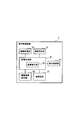
図1は、第1実施形態の表示制御装置を含む車載システムを示すブロック図であり、
図2は、各カメラによる撮影範囲を模式的に示す平面図であり、
図3は、表示制御装置を機能的に示すブロック図であり、
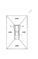
図4は、ディスプレイの表面画面に表示される画像を示す説明図であり、
図5は、表示制御装置で実施される表示制御処理を示すフローチャートであり、
図6は、表示制御装置で実施される修正画像を作成する処理を示すフローチャートであり、
図7は、第2実施形態にて設定されるマスク領域の形状や大きさを示す平面図であり、
図8は、第2実施形態において操舵角に応じてマスク領域を設定する処理を示すフローチャートであり、
図9は、第3実施形態において、ディスプレイの表面画面に表示される画像を示す説明図であり、
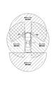
図10は、第4実施形態において各カメラの撮影領域及びその重なる範囲を示す平面図である。
以下に本発明の実施形態を図面とともに説明する。
[1.第1実施形態]
[1-1.構成]
まず、本第1実施形態の表示制御装置及び表示制御方法のシステム構成について説明する。
[1.第1実施形態]
[1-1.構成]
まず、本第1実施形態の表示制御装置及び表示制御方法のシステム構成について説明する。
図1及び図2に示すように、本第1実施形態における車載システム1は、表示制御装置3により、車両(即ち、自車両)Jに搭載された複数のカメラ5、7、9、11にて撮影された画像を用いて合成画像を作成し、その合成画像をディスプレイ13に表示するシステムである。即ち、自車両J自身の周囲の画像に基づいて合成画像を作成し、その合成画像をディスプレイ13に表示するシステムである。
詳細には、車載システム1は、表示制御装置3、複数のカメラ5~11、ディスプレイ13、ステアリングセンサ15等を備えている。
複数のカメラ5~11としては、例えば周知のCCD(Charged-Coupled Device)カメラを用いることができる。このカメラ5~11としては、自車両Jの前方を撮影する前方カメラ5、自車両Jの後方を撮影する後方カメラ7、自車両Jの左側を撮影する左カメラ9、自車両Jの右側を撮影する右カメラ11を備えている。
複数のカメラ5~11としては、例えば周知のCCD(Charged-Coupled Device)カメラを用いることができる。このカメラ5~11としては、自車両Jの前方を撮影する前方カメラ5、自車両Jの後方を撮影する後方カメラ7、自車両Jの左側を撮影する左カメラ9、自車両Jの右側を撮影する右カメラ11を備えている。
このうち、前方カメラ5は自車両Jの前部に取り付けられ、後方カメラ7は自車両Jの後部に取り付けられている。左カメラ9は左側のサイドミラー17の下部に取り付けられ、右カメラ11は右側のサイドミラー19の下部に取り付けられている。
なお、図2では、各カメラ5~11の撮影領域を、模式的に略半円形で示しているが、このような範囲に限らず、任意の形状・大きさを取りえる。
また、各カメラ5~11は、所定時間毎(例えば、33ms毎)に撮影を行い、得られた撮影画像(即ち、カメラ画像)を表示制御装置3に送るように構成されている。
また、各カメラ5~11は、所定時間毎(例えば、33ms毎)に撮影を行い、得られた撮影画像(即ち、カメラ画像)を表示制御装置3に送るように構成されている。
ステアリングセンサ15は、図示しないステアリングによって操作される車輪の角度、即ち操舵角を検出する周知のセンサである。なお、ここでは、ステアリングによって前輪の操舵角が変化する場合を例に挙げる。また、操舵角としては、左右とも絶対値を用いる。
ここで、ステアリングが左側に回転されると(即ち、切られると)、その回転角に対応した分だけ、車輪(即ち、前輪)の向きが、自車両Jを上方から見た平面視で、所定の操舵角で自車両Jの前後方向に対して左側に変更される。即ち、前輪の前方側が左側に移動する。
同様に、ステアリングが右側に回転されると、その回転角に対応した分だけ、車輪が所定の操舵角で自車両Jの前後方向に対して右側に向きが変更される。即ち、前輪の前方側が右側に移動する。
なお、ここでは、ステアリングの操作によって、車両の左右の前輪が変更される場合を例に挙げるが、それに限定されるものではない。つまり、左右の後輪の操舵角が変更される場合にも適用できる。
ディスプレイ13は、表示制御装置3から送られる映像信号に基づく画像を表示させる周知のディスプレイである。このディスプレイ13の表示画面には、後述するように、前記カメラ5~11で撮影された自車両Jの周囲のカメラ画像が視点変換された視点変換画像等が表示される。
表示制御装置3は、CPU(Central Processing Unit)21、RAM(Random Access Memory)23、ROM(Read Only Memory)25等を備えた周知のマイクロコンピュータを中心に構成された電子制御装置であり、更に、EEPROM(Electrically Erasable Programmable Read-Only Memory)27も備えている。
このうち、ROM25は、電源を切断しても記憶内容を保持する必要のあるデータやプログラムを記憶する。EEPROM27は、電源を切断しても記憶内容を保持する必要のあるデータ(例えば、画像データ)を記憶する。RAM23は、データを一時的に格納する。CPU21は、ROM25等に記憶されたプログラム等に従って処理を実行する。
前記ROM25には、後述するように、カメラ5~11により撮影されたカメラ画像を視点変換して視点変換画像を作成し、この視点変換画像に基づいて合成画像を作成し、その合成画像等をディスプレイ13に表示するための処理を実行する処理プログラムが格納されている。
また、図3に示すように、表示制御装置3は、処理プログラムが実行する処理内容として、即ち機能的に、操舵判定部31と、鳥瞰変換部33と、画像合成部35と、色識別部37と、履歴画像保存部39と、表示制御部41と、を備えており、画像合成部35には、画像修正部43を備えている。
操舵判定部31は、ステアリングセンサ15からの信号に基づいて、車輪の操舵角が自車両Jの前後方向に対して所定値以上であるか否かを判定する。
鳥瞰変換部33は、各カメラ5~11で撮影されたカメラ画像を、自車両Jの上方から見たように、例えば上方から真下又は斜め下方に見たように視点変換して視点変換画像を作成する。なお、以下では、視点変換を鳥瞰変換とし、視点変換画像を鳥瞰画像として説明する。
鳥瞰変換部33は、各カメラ5~11で撮影されたカメラ画像を、自車両Jの上方から見たように、例えば上方から真下又は斜め下方に見たように視点変換して視点変換画像を作成する。なお、以下では、視点変換を鳥瞰変換とし、視点変換画像を鳥瞰画像として説明する。
画像修正部43は、各カメラ5~11で撮影されたカメラ画像の鳥瞰画像のうち、後に詳述するように、マスク領域を置換画像で置き換えた左修正画像や右修正画像のような修正画像を作成する。
なお、マスク領域とは、車輪の画像が写る鳥瞰画像に対して、車輪の画像が表示される領域を含むように設定された領域である。具体的には、マスク領域とは、左鳥瞰画像や右鳥瞰画像における車輪の画像が表示される領域に対応して、車輪の画像の一部又は全部が表示されないように設定された領域である。
また、置換画像とは、マスク領域における車輪の画像がそのまま表示されないように、マスク領域に置き換えて表示される他の画像である。即ち、車輪の画像の表示を目立たないように抑制できる、過去に蓄積された履歴画像や所定の色で塗りつぶしたような他の画像である。
ここでは、左カメラ9及び右カメラ11による鳥瞰画像にそれぞれマスク領域が設定されるので、ステアリングの操作状態に応じて左カメラ9又は右カメラ11による鳥瞰画像の修正画像を作成する。
画像合成部35は、各カメラ5~11によるカメラ画像に基づいて得られた各鳥瞰画像を合成して合成画像を作成する。詳しくは、前後のカメラ5、7による前後の鳥瞰画像と左右のカメラ9、11による左右の修正画像とを合成して合成画像を作成する。
色識別部37は、後述するように、マスク領域に置換画像を表示するために、マスク領域の周囲の路面の色がどのような色であるかを検出する。
履歴画像保存部39は、マスク領域に置換画像として履歴画像を表示するために、過去にカメラ5~11で撮影した画像を記憶する。詳しくは、マスク領域を含む左カメラ9及び右カメラ11によって撮影されたカメラ画像の各鳥瞰画像を記憶する。なお、各鳥瞰画像のマスク領域の画像のみを履歴画像として記憶してもよい。
履歴画像保存部39は、マスク領域に置換画像として履歴画像を表示するために、過去にカメラ5~11で撮影した画像を記憶する。詳しくは、マスク領域を含む左カメラ9及び右カメラ11によって撮影されたカメラ画像の各鳥瞰画像を記憶する。なお、各鳥瞰画像のマスク領域の画像のみを履歴画像として記憶してもよい。
この履歴画像は、左カメラ9及び右カメラ11で撮影された過去の鳥瞰画像、詳しくは各鳥瞰画像において前輪の画像が表示されていない又は前輪の画像が違和感の無い程度に少ない過去の画像である。この履歴画像としては、操舵角が所定値未満の場合の画像を用いることができる。例えば、履歴画像としては、ステアリングが切られていない場合、従って、全く車輪が映っていない場合の画像等を採用できる。
表示制御部41は、後述するように、修正画像を含む合成画像等をディスプレイ13に表示する制御を行う。
なお、表示制御装置3の各種の機能は、CPU21が非遷移的実体的記録媒体に格納されたプログラムを実行することにより実現される。この例では、ROM25が、予めプログラムを格納した非遷移的実体的記録媒体(non-transitory computer readable recording medium)に該当する。また、プログラムの実行により、プログラムに対応する方法が実行される。なお、表示制御装置3を構成するマイクロコンピュータの数は1つでも複数でもよい。
なお、表示制御装置3の各種の機能は、CPU21が非遷移的実体的記録媒体に格納されたプログラムを実行することにより実現される。この例では、ROM25が、予めプログラムを格納した非遷移的実体的記録媒体(non-transitory computer readable recording medium)に該当する。また、プログラムの実行により、プログラムに対応する方法が実行される。なお、表示制御装置3を構成するマイクロコンピュータの数は1つでも複数でもよい。
[1-2.表示画面]
次に、ディスプレイ13の表示画面に表示される画像について説明する。
図4に示すように、ディスプレイ13の表示画面51には、その中心に、自車両Jの上方から見たように作成された画像が表示されている。
次に、ディスプレイ13の表示画面に表示される画像について説明する。
図4に示すように、ディスプレイ13の表示画面51には、その中心に、自車両Jの上方から見たように作成された画像が表示されている。
また、自車両Jの周囲には、各カメラ5~11で撮影されたカメラ画像から得られた鳥瞰画像等からなる合成画像が表示されている。
この合成画像は、台形の形状の4つの領域の画像から構成された画像、即ち、自車両Jが表示される中央部分が長方形に開けられた長方形の枠状の画像である。
この合成画像は、台形の形状の4つの領域の画像から構成された画像、即ち、自車両Jが表示される中央部分が長方形に開けられた長方形の枠状の画像である。
詳しくは、自車両Jの前方の台形の領域(即ち、前領域)には、前方カメラ5によるカメラ画像の鳥瞰画像(即ち、前鳥瞰画像)が表示されている。
自車両Jの後方の台形の領域(即ち、後領域)には、後方カメラ7によるカメラ画像の鳥瞰画像(即ち、後鳥瞰画像)が表示されている。
自車両Jの後方の台形の領域(即ち、後領域)には、後方カメラ7によるカメラ画像の鳥瞰画像(即ち、後鳥瞰画像)が表示されている。
自車両Jの左方の台形の領域(即ち、左領域)には、左カメラ9によるカメラ画像の鳥瞰画像(即ち、左鳥瞰画像)、又は、左鳥瞰画像が修正された修正画像(即ち、左修正画像)表示されている。
自車両Jの右方の台形の領域(即ち、右領域)には、右カメラ11によるカメラ画像の鳥瞰画像(即ち、右鳥瞰画像)、又は、右鳥瞰画像が修正された修正画像(即ち、右修正画像)表示されている。
特に、本第1実施形態では、例えば左鳥瞰画像のうち、左前輪が表示される領域の全体を覆うような範囲を左側のマスク領域M1として設定している。従って、例えば、ステアリングが左側に切られることによって、左前輪が所定値以上の操舵角となった場合には、そのマスク領域M1に、後述する履歴画像等の置換画像を貼り付けて表示し、左修正画像としている。
前記マスク領域M1としては、左前輪の張り出した画像を全て覆うような長方形を採用できる。例えば自車両Jの左側端から所定幅で前後方向に延びる短冊形の範囲を採用できる。また、このマスク領域M1の前後の範囲としては、前端は自車両Jの前端、後端は操舵角が0°における前輪の後端の位置を採用できる。
同様に、右鳥瞰画像のうち、右前輪が表示される領域の全体を覆う範囲を右側のマスク領域M2として設定している。従って、例えば、ステアリングが右側に切られることによって、右前輪が所定値以上の操舵角となった場合には、そのマスク領域M2に、履歴画像等の置換画像を貼り付けて表示し、左修正画像としている。
この右側のマスク領域M2は、上方から見た場合に、左側のマスク領域M1と左右対称となるように設けられている。従って、その形状や大きさや配置も左側のマスク領域M1と左右対称である。
このように、合成画像は、前鳥瞰画像と、後鳥瞰画像と、左鳥瞰画像又は左修正画像と、右鳥瞰画像又は右修正画像と、を一体に合成したものである。なお、各画像の境界は実際には目立たないように画像処理がなされている。
ここでは、隣り合う各画像の境界は、各画像が台形の形状となるように、例えば、自車両Jの画像の四隅から自車両Jの前後方向に対してそれぞれ45°に傾斜する角度に設定されている。
[1-3.処理]
次に、表示制御装置3にて実施される処理、即ち、ディスプレイ13の表示画面51に、合成画像等を表示する表示制御処理について説明する。
次に、表示制御装置3にて実施される処理、即ち、ディスプレイ13の表示画面51に、合成画像等を表示する表示制御処理について説明する。
<表示制御処理>
この表示制御処理は、所定時間毎に繰り返して実施される。
図5に示すように、ステップ100では、各カメラ5~11にて撮影されたカメラ画像を、各カメラ5~11から取得する。
この表示制御処理は、所定時間毎に繰り返して実施される。
図5に示すように、ステップ100では、各カメラ5~11にて撮影されたカメラ画像を、各カメラ5~11から取得する。
続くステップ110では、鳥瞰変換部33が各カメラ画像を周知の自車両Jの上方から見た鳥瞰画像にそれぞれ鳥瞰変換する。
続くステップ120では、画像修正部43が後述する修正画像を作成する処理を行う。
続くステップ120では、画像修正部43が後述する修正画像を作成する処理を行う。
続くステップ130では、画像合成部35が修正画像及び鳥瞰画像を合成して合成画像を作成する。詳しくは、前記図4に示すように、左修正画像又は右修正画像とその他の鳥瞰画像とを合成して、四角枠状の合成画像を作成する。
続くステップ140では、表示制御部41が合成画像の中心に、自車両Jの画像を貼り付けて表示した画像(即ち、表示画像)を作成する。
続くステップ150では、前記自車両Jを合成画像の中央に貼り付けて表示した表示画像をディスプレイ13に表示して、一旦本処理を終了する。
続くステップ150では、前記自車両Jを合成画像の中央に貼り付けて表示した表示画像をディスプレイ13に表示して、一旦本処理を終了する。
<修正画像作成処理>
次に、前記ステップ120にて実施される左修正画像や右修正画像のような修正画像を作成する処理について説明する。
次に、前記ステップ120にて実施される左修正画像や右修正画像のような修正画像を作成する処理について説明する。
図6に示すように、ステップ200では、操舵判定部31がステアリングセンサ15からの信号に基づいて、車輪(即ち、前輪)の操舵角が所定値以上であるか否かを判定する。ここで、肯定判断されるとステップ210に進み、一方否定判断されると一旦本処理を終了する。
なお、ここでは、操舵判定部31がステアリングセンサ15からの信号に基づいて、ステアリングが右又は左のどちらに回された場合の操舵角であるかも検出する。
ここで、操舵角とは、上述したように、自車両の前後方向に対して車輪がどの程度の角度で曲げられたかを示す値(即ち、絶対値)である。詳しくは、前後方向と車輪を上方から見た場合の長手方向とのなす角である。
ここで、操舵角とは、上述したように、自車両の前後方向に対して車輪がどの程度の角度で曲げられたかを示す値(即ち、絶対値)である。詳しくは、前後方向と車輪を上方から見た場合の長手方向とのなす角である。
この操舵角を判定する所定値は、実際に、どの程度の操舵角の場合に違和感のある車輪の表示がなされるかを実験等によって調べることによって設定することができる。
ステップ210では、操舵角が大きいので、メモリであるEEPROM27に履歴画像があるか否かを判定する。ここで肯定判断されるとステップ220に進み、一方否定判断されるとステップ230に進む。
ステップ210では、操舵角が大きいので、メモリであるEEPROM27に履歴画像があるか否かを判定する。ここで肯定判断されるとステップ220に進み、一方否定判断されるとステップ230に進む。
このEEPROM27には、過去に撮影された自車両の周辺の画像が、逐次記憶されている。詳しくは、左のマスク領域M1を含む左カメラ9の左鳥瞰画像と、右のマスク領域M2を含む右カメラ11の右鳥瞰画像とを記憶している。なお、左のマスク領域M1と右のマスク領域M2との鳥瞰画像を記憶してもよい。
ステップ220では、画像修正部43はステアリングが回される方向、即ちステアリングが切られる方向に応じて、左鳥瞰画像又は右鳥瞰画像において車輪を覆う領域(即ち、マスク領域)を、履歴画像でマスクして、修正画像を作成する。つまり、マスク領域の画像を履歴画像で置換して修正画像を作成する。
例えば、ステアリングが左に切られて操舵角が所定値以上になった場合には、左前輪の車輪の画像を消去するために、左のマスク領域M1に、このマスク領域M1に対応した履歴画像を貼り付けて左修正画像を作成する。
このとき、右のマスク領域M2については、履歴画像を貼り付けないが、左のマスク領域M1と同様に、対応する履歴画像を貼り付けてもよい。
一方、ステアリングが右に切られて操舵角が所定値以上になった場合には、右前輪の車輪の画像を消去するために、右のマスク領域M2に、このマスク領域M2の履歴画像を貼り付けて右修正画像を作成する。
一方、ステアリングが右に切られて操舵角が所定値以上になった場合には、右前輪の車輪の画像を消去するために、右のマスク領域M2に、このマスク領域M2の履歴画像を貼り付けて右修正画像を作成する。
このとき、左のマスク領域M1については、履歴画像を貼り付けないが、右のマスク領域M1と同様に履歴画像を貼り付けてもよい。
一方、ステップ230では、メモリに履歴画像が無いので、履歴画像とは異なる他の置換画像を用い、履歴画像によるマスクと同様にして、マスク領域に置換画像を貼り付けて、各修正画像を作成する。
一方、ステップ230では、メモリに履歴画像が無いので、履歴画像とは異なる他の置換画像を用い、履歴画像によるマスクと同様にして、マスク領域に置換画像を貼り付けて、各修正画像を作成する。
例えば、ステアリングが左に切られて操舵角が所定値以上になった場合には、左のマスク領域M1に、置換画像を貼り付けて左修正画像を作成する。
一方、ステアリングが右に切られて操舵角が所定値以上になった場合には、右のマスク領域M2に、置換画像を貼り付けて右修正画像を作成する。
一方、ステアリングが右に切られて操舵角が所定値以上になった場合には、右のマスク領域M2に、置換画像を貼り付けて右修正画像を作成する。
この置換画像としては、マスク領域の周囲の画像と同様な画像を用いることが好ましい。そこで、色識別部37にてマスク領域の周囲の画像の色を認識し、その色と同じか又はできる限り近い色で塗りつぶした置換画像、あるいは所定の画像を有する置換画像を作成する。
[1-4.効果]
以上詳述した本実施形態によれば、下記の効果が得られる。
(1a)本第1実施形態によれば、各カメラ5~11で撮影されたカメラ画像から各鳥瞰画像を作成する。そして、自車両Jの車輪の操舵角が所定値以上か否かを判定し、操舵角が所定値以上の場合には、対応するマスク領域に、履歴画像を貼り付けるか又は所定の色で塗りつぶされた他の置換画像を貼り付けて修正画像を作成する。その後、修正画像と他の鳥瞰画像とを合成して合成画像を作成し、自車両Jを示す画像とともに、ディスプレイ13に表示する。
以上詳述した本実施形態によれば、下記の効果が得られる。
(1a)本第1実施形態によれば、各カメラ5~11で撮影されたカメラ画像から各鳥瞰画像を作成する。そして、自車両Jの車輪の操舵角が所定値以上か否かを判定し、操舵角が所定値以上の場合には、対応するマスク領域に、履歴画像を貼り付けるか又は所定の色で塗りつぶされた他の置換画像を貼り付けて修正画像を作成する。その後、修正画像と他の鳥瞰画像とを合成して合成画像を作成し、自車両Jを示す画像とともに、ディスプレイ13に表示する。
このような構成によれば、例えばステアリングが大きく切られて、車輪の操舵角が大きくなった場合には、車両の周囲を示す合成画像に、車輪の画像が表示されないようにすることができる。
つまり、車両の周囲を示す合成画像において、通常の車輪の位置とは異なる位置から大きく斜め方向に張り出すように変形した車輪が表示されることを抑制できる。
よって、車両の乗員がディスプレイ13に表示された表示画像を見た場合でも、違和感が生じにくいという効果がある。
よって、車両の乗員がディスプレイ13に表示された表示画像を見た場合でも、違和感が生じにくいという効果がある。
なお、車輪の画像を全て消去するように、マスク領域を設定することが望ましいが、車輪の一部の画像、例えば前輪が大きく張り出す部分の先端側や車輪の前部の画像を消去しても、違和感が減少する効果がある。
(1b)また、マスク領域に所定の色で塗りつぶされた置換画像を貼り付ける場合には、マスク領域の周囲の色にできる限り近い色を用いるので、違和感が少ないという利点がある。
[1-5.特許請求の範囲と実施形態との関係]
以上説明した第1実施形態において、自車両J、カメラ5~11、ディスプレイ13、表示制御装置3、操舵判定部31、鳥瞰変換部33、画像合成部35、履歴画像保存部39、画像修正部43、表示制御部41が、それぞれ、本発明における、自車両、カメラ、表示装置、表示制御装置、操舵判定部、視点変換部、画像合成部、メモリ、画像修正部、表示制御部の一例に相当する。
以上説明した第1実施形態において、自車両J、カメラ5~11、ディスプレイ13、表示制御装置3、操舵判定部31、鳥瞰変換部33、画像合成部35、履歴画像保存部39、画像修正部43、表示制御部41が、それぞれ、本発明における、自車両、カメラ、表示装置、表示制御装置、操舵判定部、視点変換部、画像合成部、メモリ、画像修正部、表示制御部の一例に相当する。
[2.第2実施形態]
次に、第2実施形態について説明するが、前記第1実施形態と同様な内容の説明は省略する。
次に、第2実施形態について説明するが、前記第1実施形態と同様な内容の説明は省略する。
なお、本第2実施形態におけるハード構成は、前記第1実施形態と同様であるので、同じ構成には同じ番号を用いて説明する。
本第2実施形態は、画像修正部43がマスク領域の大きさを操舵角に応じて変更するものである。
本第2実施形態は、画像修正部43がマスク領域の大きさを操舵角に応じて変更するものである。
例えば自車両Jの前輪の左のマスク領域M1を考えた場合、例えば図7に示すように、自車両Jに近い側(即ち、右側)より、第1マスク領域m1、第2マスク領域m2に区分する。なお、それ以上に区分してもよい。
この第1マスク領域m1と第2マスク領域m2とは、マスク領域M1を図7において左右対称になるように2等分したものである。また、この第1マスク領域m1と第2マスク領域m2とは、操舵角に応じて使用する範囲が異なるように設定されている。
詳しくは、操舵角が前記所定値以上~最大の操舵角の1/2未満の範囲(即ち、第1操舵角)の場合には、マスク領域M1として、第1マスク領域m1が使用される。即ち、操舵角が小さい場合には、車輪の張り出しが少ないので、幅の狭い第1マスク領域m1が使用される。
一方、操舵角が最大の操舵角の1/2~最大値の範囲(即ち、第2操舵角)の場合には、マスク領域M1として、第1マスク領域m1と第2マスク領域m2との両方が使用される。即ち、操舵角が大きい場合には、車輪の張り出しが多いので、幅の広い第1マスク領域m1及び第2マスク領域m2が使用される。
次に、本第2実施形態におけるマスク領域を設定する処理について説明する。
図8に示すように、ステップ300では、ステアリングセンサ15が操舵角を検出する。
続くステップ310では、操舵角に対応した範囲のマスク領域M1を設定し、一旦本処理を終了する。
図8に示すように、ステップ300では、ステアリングセンサ15が操舵角を検出する。
続くステップ310では、操舵角に対応した範囲のマスク領域M1を設定し、一旦本処理を終了する。
つまり、操舵角が第1操舵角の場合には、置換画像を貼り付けるマスク領域M1として第1マスク領域m1を設定し、操舵角が第1操舵角より大きな第2操舵角の場合には、置換画像を貼り付けるマスク領域M1として第1マスク領域m1と第2マスク領域m2を合わせたマスク領域M1を設定する。
なお、マスク領域M1を操舵角によって設定した後には、前記第1実施形態と同様に、設定されたマスク領域M1に対応した大きさの置換画像を貼り付けて修正画像を作成する。
なお、ここでは、自車両Jの前輪の左のマスク領域M1を例に挙げたが、左右のマスク領域M1、M2は左右対称であるので、左のマスク領域M1と左右対称に右のマスク領域M2を設定することにより、右のマスク領域M2についても同様にして修正画像を作成することができる。
本第2実施形態では、画像修正部43が操舵角の大きさに応じて、詳しくは、操舵角が大きくなるほどマスク領域が大きくなるように設定する。よって、車輪の張り出し状態に対応して、できる限り少ない面積のマスク領域を設定できるので、第1実施形態の効果を奏するとともに、一層違和感を低減できるという効果がある。
[3.第3実施形態]
次に、第3実施形態について説明するが、前記第1実施形態と同様な内容の説明は省略する。
次に、第3実施形態について説明するが、前記第1実施形態と同様な内容の説明は省略する。
なお、本第3実施形態におけるハード構成は、前記第1実施形態と同様であるので、同じ構成には同じ番号を用いて説明する。
本第3実施形態は、第1実施形態のようなマスク領域を設けるのではなく、操舵角が前記所定値以上に大きな場合には、自車両Jの画像を前記マスク領域を覆うように大きく表示するものである。
本第3実施形態は、第1実施形態のようなマスク領域を設けるのではなく、操舵角が前記所定値以上に大きな場合には、自車両Jの画像を前記マスク領域を覆うように大きく表示するものである。
具体的には、図9に示すように、操舵角が所定値以上の場合には、表示画面51の中央に自車両Jを表示するが、この自車両Jの大きさは、第1実施形態の図4に示す自車両の大きさよりも大きい。
つまり、操舵角が所定値未満の場合には、前記図4に示すように、表示画面51の中央に小さな画像にて自車両Jを表示するとともに、その周囲に、左右のマスク領域M1、M2に置換画像が貼り付けられた修正画像を含む合成画像を表示する。
一方、操舵角が所定値以上の場合には、前記図9に示すように、前記図4におけるマスク領域M1、M2を覆うような大きさにて、合成画像に大きな自車両Jを貼り付けて表示する。なお、周囲の合成画像は拡大することなくそのままの拡大率で利用する。
本第3実施形態では、画像修正部43が操舵角の大きさに応じて、詳しくは、操舵角が大きくなるほど自車両の画像を大きくするように設定する。よって、第1実施形態の効果を奏するとともに、一層違和感を低減できるという効果がある。
[4.第4実施形態]
次に、第4実施形態について説明するが、前記第1実施形態と同様な内容の説明は省略する。
次に、第4実施形態について説明するが、前記第1実施形態と同様な内容の説明は省略する。
なお、本第4実施形態におけるハード構成は、前記第1実施形態と同様であるので、同じ構成には同じ番号を用いて説明する。
本第4実施形態は、各カメラ5~11の撮影領域が重なっている場合には、画像修正部43がその撮影領域が重なっているカメラ5~11の画像のブレンド率、例えばαブレンドによるブレンド率を変更して合成画像を作成する。
本第4実施形態は、各カメラ5~11の撮影領域が重なっている場合には、画像修正部43がその撮影領域が重なっているカメラ5~11の画像のブレンド率、例えばαブレンドによるブレンド率を変更して合成画像を作成する。
本第4実施形態では、例えば図10に示すように、前方カメラ5の撮影領域が180°以上と広く、左右のカメラ9、11の撮影領域の前方側の一部が重なっている。詳しくは、それによって、前記第1実施形態における左右のマスク領域M1、M2の一部又は全体が、撮影領域の重なっている範囲に含まれている。
この場合には、撮影領域が重なっている範囲では、前方カメラ5の撮影領域の前鳥瞰画像ブレンド率を100%とし、左カメラ9及び右カメラ11の撮影領域の左鳥瞰画像及び右鳥瞰画像のブレンド率を0%とする。
つまり、前方カメラ5で撮影されたカメラ画像を鳥瞰変換した場合には、左右のカメラ9、11で撮影されたカメラ画像を鳥瞰変換した場合に比べて、車輪(即ち、前輪)が写りにくく、よって、車輪の画像の歪みや位置のずれが少ないので、表示された合成画像に対する違和感が低減するという効果がある。
[5.他の実施形態]
以上、本発明の実施形態について説明したが、本発明は前記実施形態に限定されるものではなく、本発明の技術的範囲に属する限り種々の形態を採ることができる。
以上、本発明の実施形態について説明したが、本発明は前記実施形態に限定されるものではなく、本発明の技術的範囲に属する限り種々の形態を採ることができる。
(5a)例えば、前記実施形態では、左右の前輪に対してマスク領域を設定したが、後輪の操舵角が変化する場合には、後輪に対しても上述した各実施形態と同様に、後輪が写る鳥瞰画像に対してマスク領域を設定し、修正画像を作製して表示してもよい。
この場合にも、マスク領域は、後輪について違和感のある画像の一部又は全体が表示されないように設定すればよい。
(5b)また、マスク領域の範囲は、自車両の側端から張り出す車輪の画像を全て覆う範囲としてもよいが、例えば、大きく張り出す車輪の先端側等、車輪の画像の一部をマスクするように設定してもよい。
(5b)また、マスク領域の範囲は、自車両の側端から張り出す車輪の画像を全て覆う範囲としてもよいが、例えば、大きく張り出す車輪の先端側等、車輪の画像の一部をマスクするように設定してもよい。
(5c)或いは、マスク領域における車輪の画像を表示しないようにするのではなく、車輪の画像の表示を抑制して、目立たないようにしてもよい。例えば、車輪であることを認識しにくくするように、マスク領域の車輪が写る画像に、他の路面等の画像を例えば半透過にて重ね合わせてもよい。このときには、マスク領域の色を周囲の色に近づけるようにすることが好ましい。或いは、マスク領域にメッシュ等の模様を入れるようにしてもよい。
(5d)履歴画像以外の置換画像としては、所定の色で塗りつぶした画像を採用できるが、他の模様等で塗りつぶしてもよい。
(5e)前記実施形態では、操舵角をステアリングセンサによって検出したが、それに限定されるものではない。例えば車輪の画像は操舵角によって変化するので、車輪が写った鳥瞰画像等から操舵角を求めてもよい。
(5e)前記実施形態では、操舵角をステアリングセンサによって検出したが、それに限定されるものではない。例えば車輪の画像は操舵角によって変化するので、車輪が写った鳥瞰画像等から操舵角を求めてもよい。
(5f)また、前記実施形態における1つの構成要素が有する機能を複数の構成要素として分散させたり、複数の構成要素が有する機能を1つの構成要素に統合させたりしてもよい。また、前記実施形態の構成の一部を省略してもよい。また、前記実施形態の構成の少なくとも一部を、他の前記実施形態の構成に対して付加又は置換してもよい。なお、特許請求の範囲に記載した文言のみによって特定される技術思想に含まれるあらゆる態様が本発明の実施形態である。
(5g)さらに、上述した表示制御装置の他、当該表示制御装置を構成要素とするシステム、当該表示制御装置としてコンピュータを機能させるためのプログラム、このプログラムを記録した半導体メモリ等の非遷移的実体的記録媒体、表示制御を行う方法など、種々の形態で本発明を実現することもできる。
また、表示制御装置が実行する機能の一部又は全部を、一つあるいは複数のIC等によりハードウェア的に構成してもよい。
本開示は、実施例に準拠して記述されたが、本開示は当該実施例や構造に限定されるものではないと理解される。本開示は、様々な変形例や均等範囲内の変形をも包含する。加えて、様々な組み合わせや形態、さらには、それらの一要素のみ、それ以上、あるいはそれ以下、を含む他の組み合わせや形態をも、本開示の範疇や思想範囲に入るものである。
3…表示制御装置、5…前方カメラ、7…後方カメラ、9…左カメラ、11…右カメラ、15…ステアリングセンサ、13…ディスプレイ、31…操舵判定部、33…鳥瞰変換部、35…画像合成部、37…色識別部、39…履歴画像保存部、41…表示制御部、43…画像修正部、J…自車両
Claims (13)
- 自車両(J)に取り付けられた複数のカメラ(5~11)によって撮影された画像を、それぞれ前記自車両の上方から見た視点変換画像に視点変換する視点変換部(33)と、
前記自車両の車輪の操舵角が所定値以上か否かを判定する操舵判定部(31)と、
前記操舵角が所定値以上の場合には、前記視点変換画像のうち前記車輪が写る視点変換画像に対して、前記車輪の画像の表示を抑制する処理を行って修正画像を作成する画像修正部(43)と、
前記修正画像と該修正画像とは異なる他の前記視点変換画像とを合成して合成画像を作成する画像合成部(35)と、
表示装置(13)に、前記合成画像と前記自車両の位置に前記自車両の画像とを表示する表示制御部(41)と、
を備えた表示制御装置。 - 請求項1に記載の表示制御装置であって、
前記修正画像は、前記視点変換画像において、前記車輪の画像が表示される領域を含むように設定されたマスク領域に、前記車輪の画像とは異なる置換画像を表示した画像である、表示制御装置。 - 請求項2に記載の表示制御装置であって、
前記マスク領域に表示する置換画像として、前記カメラによって過去に撮影された前記マスク領域における履歴画像を用いる表示制御装置。 - 請求項3に記載の表示制御装置であって、
前記画像修正部は、メモリに前記履歴画像が記憶されているか否かを判定し、前記履歴画像が記憶されている場合には、前記マスク領域に前記置換画像として前記履歴画像を表示し、前記履歴画像が記憶されていない場合には、前記マスク領域に前記履歴画像とは異なる他の置換画像を表示する、表示制御装置。 - 請求項2または請求項4に記載の表示制御装置であって、
前記マスク領域に表示する置換画像として、所定の色又は模様を有する置換画像を用いる表示制御装置。 - 請求項5に記載の表示制御装置であって、
前記画像修正部は、前記マスク領域の周囲の画像に基づいて、前記置換画像を作成する、表示制御装置。 - 請求項2から請求項6までのいずれか1項に記載の表示制御装置であって、
前記画像修正部は、前記操舵角が大きくなるほど、前記マスク領域を大きくする、表示制御装置。 - 請求項1から請求項7までのいずれか1項に記載の表示制御装置であって、
前記画像修正部は、前記視点変換画像における前記自車両の位置に、前記自車両を示す画像を表示するとともに、前記操舵角が所定値以上の場合には、前記操舵角が所定値未満の場合に比べて、前記自車両の画像を大きくする、表示制御装置。 - 請求項1に記載の表示制御装置であって、
前記画像修正部は、前記各カメラの撮影領域が重なっている範囲に前記車輪の画像が表示される領域がある場合には、前記該撮影領域が重なっているカメラの画像のブレンド率を変更して、前記車輪の画像の表示を抑制する、表示制御装置。 - 請求項1から請求項9までのいずれか1項に記載の表示制御装置であって、
前記操舵角を、ステアリングセンサ(15)からの信号又は前記車輪の画像により検出する表示制御装置。 - 自車両(J)に取り付けられた複数のカメラ(5~11)によって撮影された画像を、それぞれ前記自車両の上方から見た視点変換画像に視点変換する視点変換ステップと、
前記自車両の車輪の操舵角が所定値以上か否かを判定する操舵判定ステップと、
前記操舵角が所定値以上の場合には、前記視点変換画像のうち前記車輪が写る視点変換画像に対して、前記車輪の画像の表示を抑制する処理を行って修正画像を作成する画像修正ステップと、
前記修正画像と該修正画像とは異なる他の前記視点変換画像とを合成して合成画像を作成する画像合成ステップと、
表示装置(13)に、前記合成画像と前記自車両の位置に前記自車両の画像とを表示する表示制御ステップと、
を備えた表示制御方法。 - 請求項11に記載の表示制御方法であって、
前記画像修正ステップは、前記操舵角が大きくなるほど、前記車輪の画像が表示される領域を含むように設定されたマスク領域を大きくする、表示制御方法。 - 請求項11又は請求項12に記載の表示制御方法であって、
前記画像修正ステップは、前記視点変換画像における前記自車両の位置に、前記自車両を示す画像を表示するとともに、前記操舵角が所定値以上の場合には、前記操舵角が所定値未満の場合に比べて、前記自車両の画像を大きくする、表示制御方法。
Priority Applications (3)
| Application Number | Priority Date | Filing Date | Title |
|---|---|---|---|
| US16/062,480 US10427603B2 (en) | 2015-12-18 | 2016-12-15 | Display control device and display control method |
| CN201680073504.3A CN108370433B (zh) | 2015-12-18 | 2016-12-15 | 显示控制装置以及显示控制方法 |
| DE112016005781.4T DE112016005781B4 (de) | 2015-12-18 | 2016-12-15 | Anzeigesteuerungsvorrichtung und Anzeigesteuerungsverfahren |
Applications Claiming Priority (2)
| Application Number | Priority Date | Filing Date | Title |
|---|---|---|---|
| JP2015-247714 | 2015-12-18 | ||
| JP2015247714A JP6561824B2 (ja) | 2015-12-18 | 2015-12-18 | 表示制御装置 |
Publications (1)
| Publication Number | Publication Date |
|---|---|
| WO2017104768A1 true WO2017104768A1 (ja) | 2017-06-22 |
Family
ID=59056604
Family Applications (1)
| Application Number | Title | Priority Date | Filing Date |
|---|---|---|---|
| PCT/JP2016/087439 Ceased WO2017104768A1 (ja) | 2015-12-18 | 2016-12-15 | 表示制御装置及び表示制御方法 |
Country Status (5)
| Country | Link |
|---|---|
| US (1) | US10427603B2 (ja) |
| JP (1) | JP6561824B2 (ja) |
| CN (1) | CN108370433B (ja) |
| DE (1) | DE112016005781B4 (ja) |
| WO (1) | WO2017104768A1 (ja) |
Families Citing this family (4)
| Publication number | Priority date | Publication date | Assignee | Title |
|---|---|---|---|---|
| CN109691088B (zh) * | 2016-08-22 | 2022-04-15 | 索尼公司 | 图像处理设备、图像处理方法、以及程序 |
| EP4131945B1 (en) * | 2020-03-31 | 2025-11-05 | Honda Motor Co., Ltd. | Image processing device, vehicle, image processing method, and program |
| DE102021212970A1 (de) * | 2021-11-18 | 2023-05-25 | Continental Autonomous Mobility Germany GmbH | Verfahren und Vorrichtung zum Erzeugen einer Surround-Ansicht, und Kraftfahrzeug |
| JP2023082954A (ja) * | 2021-12-03 | 2023-06-15 | 本田技研工業株式会社 | 制御装置、制御方法、及び制御プログラム |
Citations (3)
| Publication number | Priority date | Publication date | Assignee | Title |
|---|---|---|---|---|
| JP2004213489A (ja) * | 2003-01-07 | 2004-07-29 | Nissan Motor Co Ltd | 車両用運転支援装置 |
| JP2009071790A (ja) * | 2007-09-18 | 2009-04-02 | Denso Corp | 車両周辺監視装置 |
| JP2010114618A (ja) * | 2008-11-06 | 2010-05-20 | Clarion Co Ltd | 車両周辺監視システム |
Family Cites Families (16)
| Publication number | Priority date | Publication date | Assignee | Title |
|---|---|---|---|---|
| JP4156214B2 (ja) | 2001-06-13 | 2008-09-24 | 株式会社デンソー | 車両周辺画像処理装置及び記録媒体 |
| JP2009017020A (ja) * | 2007-07-02 | 2009-01-22 | Nissan Motor Co Ltd | 画像処理装置及び表示画像生成方法 |
| JP5132249B2 (ja) * | 2007-10-23 | 2013-01-30 | アルパイン株式会社 | 車載用撮像装置 |
| US8694195B2 (en) * | 2007-12-04 | 2014-04-08 | Volkswagen Ag | Motor vehicle having a wheel-view camera and method for controlling a wheel-view camera system |
| JP5344227B2 (ja) * | 2009-03-25 | 2013-11-20 | アイシン精機株式会社 | 車両用周辺監視装置 |
| CN101995239B (zh) * | 2009-08-11 | 2012-05-23 | 财团法人车辆研究测试中心 | 利用鸟瞰影像判断障碍物的系统及方法 |
| US9204108B2 (en) * | 2009-12-07 | 2015-12-01 | Clarion Co., Ltd. | Vehicle periphery monitoring system |
| JP5728929B2 (ja) | 2010-12-20 | 2015-06-03 | 日産自動車株式会社 | 車両周辺監視装置 |
| CN104285441B (zh) * | 2012-05-22 | 2018-01-05 | 三菱电机株式会社 | 图像处理装置 |
| EP2981077B1 (en) * | 2013-03-28 | 2017-09-27 | Aisin Seiki Kabushiki Kaisha | Periphery monitoring device and program |
| JP5971223B2 (ja) * | 2013-10-16 | 2016-08-17 | 株式会社デンソー | 合成画像生成装置 |
| JP6255928B2 (ja) * | 2013-11-15 | 2018-01-10 | スズキ株式会社 | 俯瞰画像生成装置 |
| GB2535536B (en) * | 2015-02-23 | 2020-01-01 | Jaguar Land Rover Ltd | Apparatus and method for displaying information |
| JP6609970B2 (ja) * | 2015-04-02 | 2019-11-27 | アイシン精機株式会社 | 周辺監視装置 |
| DE102015208343B4 (de) * | 2015-05-06 | 2023-09-07 | Robert Bosch Gmbh | Verfahren zum Erzeugen eines Gesamtbildes einer Fahrzeugumgebung eines Fahrzeuges und entsprechende Vorrichtung |
| CN105128760B (zh) * | 2015-08-27 | 2018-10-16 | 惠州华阳通用电子有限公司 | 倒车轨迹描绘方法及装置 |
-
2015
- 2015-12-18 JP JP2015247714A patent/JP6561824B2/ja not_active Expired - Fee Related
-
2016
- 2016-12-15 CN CN201680073504.3A patent/CN108370433B/zh active Active
- 2016-12-15 DE DE112016005781.4T patent/DE112016005781B4/de active Active
- 2016-12-15 WO PCT/JP2016/087439 patent/WO2017104768A1/ja not_active Ceased
- 2016-12-15 US US16/062,480 patent/US10427603B2/en active Active
Patent Citations (3)
| Publication number | Priority date | Publication date | Assignee | Title |
|---|---|---|---|---|
| JP2004213489A (ja) * | 2003-01-07 | 2004-07-29 | Nissan Motor Co Ltd | 車両用運転支援装置 |
| JP2009071790A (ja) * | 2007-09-18 | 2009-04-02 | Denso Corp | 車両周辺監視装置 |
| JP2010114618A (ja) * | 2008-11-06 | 2010-05-20 | Clarion Co Ltd | 車両周辺監視システム |
Also Published As
| Publication number | Publication date |
|---|---|
| CN108370433A (zh) | 2018-08-03 |
| US10427603B2 (en) | 2019-10-01 |
| JP6561824B2 (ja) | 2019-08-21 |
| DE112016005781B4 (de) | 2023-09-21 |
| CN108370433B (zh) | 2020-05-26 |
| US20180361933A1 (en) | 2018-12-20 |
| DE112016005781T5 (de) | 2018-09-13 |
| JP2017112574A (ja) | 2017-06-22 |
Similar Documents
| Publication | Publication Date | Title |
|---|---|---|
| JP2009017020A (ja) | 画像処理装置及び表示画像生成方法 | |
| EP3142066B1 (en) | Image synthesizer for a surround monitoring system | |
| EP4028288B1 (en) | Sensor fusion based perceptually enhanced surround view | |
| CA2942559C (en) | Systems and methods for processing and editing all celestial sphere images | |
| JP6561824B2 (ja) | 表示制御装置 | |
| JP2009100095A (ja) | 画像処理装置及び画像処理方法 | |
| JP5404932B2 (ja) | 交通状況のビデオデータと間隔データを組み合わせて視覚的に表示するための方法および装置 | |
| CN102273201A (zh) | 车辆用周边监视装置以及车辆用周边图像显示方法 | |
| CN113678433A (zh) | 车辆周边图像生成装置、车辆周边显示系统及车辆周边显示方法 | |
| JP6740991B2 (ja) | 表示処理装置 | |
| US10399496B2 (en) | Viewing device for vehicle and method of displaying viewed image for vehicle | |
| US8929605B2 (en) | Image processing method and image processing apparatus for generating vehicular image | |
| JP2007141098A (ja) | 画像処理装置及び画像処理方法 | |
| TWI443604B (zh) | 影像校正方法及影像校正裝置 | |
| US20250310648A1 (en) | Apparatus and method for surround-view monitoring for a vehicle | |
| WO2017111084A1 (ja) | 表示制御装置及び表示制御方法 | |
| KR20180040469A (ko) | 이미지 정합 방법 및 장치 | |
| WO2020137583A1 (ja) | 画像生成装置及び画像表示システム | |
| CN102469249B (zh) | 影像校正方法及影像校正装置 | |
| JP6149379B2 (ja) | 画像表示制御装置 | |
| JP6330761B2 (ja) | 画像生成装置、画像生成方法、及びプログラム | |
| JP2024079872A (ja) | 表示制御装置、表示制御方法およびプログラム | |
| JP2010178018A (ja) | 車両の周辺を画像表示するための装置 | |
| WO2014010179A1 (ja) | 車両用視界支援装置 | |
| CN107548501B (zh) | 用于驾驶员辅助系统的图像合成装置 |
Legal Events
| Date | Code | Title | Description |
|---|---|---|---|
| 121 | Ep: the epo has been informed by wipo that ep was designated in this application |
Ref document number: 16875745 Country of ref document: EP Kind code of ref document: A1 |
|
| WWE | Wipo information: entry into national phase |
Ref document number: 112016005781 Country of ref document: DE |
|
| 122 | Ep: pct application non-entry in european phase |
Ref document number: 16875745 Country of ref document: EP Kind code of ref document: A1 |