WO2017104033A1 - Device and method for controlling hybrid system - Google Patents
Device and method for controlling hybrid system Download PDFInfo
- Publication number
- WO2017104033A1 WO2017104033A1 PCT/JP2015/085293 JP2015085293W WO2017104033A1 WO 2017104033 A1 WO2017104033 A1 WO 2017104033A1 JP 2015085293 W JP2015085293 W JP 2015085293W WO 2017104033 A1 WO2017104033 A1 WO 2017104033A1
- Authority
- WO
- WIPO (PCT)
- Prior art keywords
- control device
- motor generator
- electric supercharger
- power storage
- electronic control
- Prior art date
Links
Images


Classifications
-
- B—PERFORMING OPERATIONS; TRANSPORTING
- B60—VEHICLES IN GENERAL
- B60K—ARRANGEMENT OR MOUNTING OF PROPULSION UNITS OR OF TRANSMISSIONS IN VEHICLES; ARRANGEMENT OR MOUNTING OF PLURAL DIVERSE PRIME-MOVERS IN VEHICLES; AUXILIARY DRIVES FOR VEHICLES; INSTRUMENTATION OR DASHBOARDS FOR VEHICLES; ARRANGEMENTS IN CONNECTION WITH COOLING, AIR INTAKE, GAS EXHAUST OR FUEL SUPPLY OF PROPULSION UNITS IN VEHICLES
- B60K6/00—Arrangement or mounting of plural diverse prime-movers for mutual or common propulsion, e.g. hybrid propulsion systems comprising electric motors and internal combustion engines ; Control systems therefor, i.e. systems controlling two or more prime movers, or controlling one of these prime movers and any of the transmission, drive or drive units Informative references: mechanical gearings with secondary electric drive F16H3/72; arrangements for handling mechanical energy structurally associated with the dynamo-electric machine H02K7/00; machines comprising structurally interrelated motor and generator parts H02K51/00; dynamo-electric machines not otherwise provided for in H02K see H02K99/00
- B60K6/20—Arrangement or mounting of plural diverse prime-movers for mutual or common propulsion, e.g. hybrid propulsion systems comprising electric motors and internal combustion engines ; Control systems therefor, i.e. systems controlling two or more prime movers, or controlling one of these prime movers and any of the transmission, drive or drive units Informative references: mechanical gearings with secondary electric drive F16H3/72; arrangements for handling mechanical energy structurally associated with the dynamo-electric machine H02K7/00; machines comprising structurally interrelated motor and generator parts H02K51/00; dynamo-electric machines not otherwise provided for in H02K see H02K99/00 the prime-movers consisting of electric motors and internal combustion engines, e.g. HEVs
- B60K6/22—Arrangement or mounting of plural diverse prime-movers for mutual or common propulsion, e.g. hybrid propulsion systems comprising electric motors and internal combustion engines ; Control systems therefor, i.e. systems controlling two or more prime movers, or controlling one of these prime movers and any of the transmission, drive or drive units Informative references: mechanical gearings with secondary electric drive F16H3/72; arrangements for handling mechanical energy structurally associated with the dynamo-electric machine H02K7/00; machines comprising structurally interrelated motor and generator parts H02K51/00; dynamo-electric machines not otherwise provided for in H02K see H02K99/00 the prime-movers consisting of electric motors and internal combustion engines, e.g. HEVs characterised by apparatus, components or means specially adapted for HEVs
- B60K6/24—Arrangement or mounting of plural diverse prime-movers for mutual or common propulsion, e.g. hybrid propulsion systems comprising electric motors and internal combustion engines ; Control systems therefor, i.e. systems controlling two or more prime movers, or controlling one of these prime movers and any of the transmission, drive or drive units Informative references: mechanical gearings with secondary electric drive F16H3/72; arrangements for handling mechanical energy structurally associated with the dynamo-electric machine H02K7/00; machines comprising structurally interrelated motor and generator parts H02K51/00; dynamo-electric machines not otherwise provided for in H02K see H02K99/00 the prime-movers consisting of electric motors and internal combustion engines, e.g. HEVs characterised by apparatus, components or means specially adapted for HEVs characterised by the combustion engines
-
- B—PERFORMING OPERATIONS; TRANSPORTING
- B60—VEHICLES IN GENERAL
- B60K—ARRANGEMENT OR MOUNTING OF PROPULSION UNITS OR OF TRANSMISSIONS IN VEHICLES; ARRANGEMENT OR MOUNTING OF PLURAL DIVERSE PRIME-MOVERS IN VEHICLES; AUXILIARY DRIVES FOR VEHICLES; INSTRUMENTATION OR DASHBOARDS FOR VEHICLES; ARRANGEMENTS IN CONNECTION WITH COOLING, AIR INTAKE, GAS EXHAUST OR FUEL SUPPLY OF PROPULSION UNITS IN VEHICLES
- B60K6/00—Arrangement or mounting of plural diverse prime-movers for mutual or common propulsion, e.g. hybrid propulsion systems comprising electric motors and internal combustion engines ; Control systems therefor, i.e. systems controlling two or more prime movers, or controlling one of these prime movers and any of the transmission, drive or drive units Informative references: mechanical gearings with secondary electric drive F16H3/72; arrangements for handling mechanical energy structurally associated with the dynamo-electric machine H02K7/00; machines comprising structurally interrelated motor and generator parts H02K51/00; dynamo-electric machines not otherwise provided for in H02K see H02K99/00
- B60K6/20—Arrangement or mounting of plural diverse prime-movers for mutual or common propulsion, e.g. hybrid propulsion systems comprising electric motors and internal combustion engines ; Control systems therefor, i.e. systems controlling two or more prime movers, or controlling one of these prime movers and any of the transmission, drive or drive units Informative references: mechanical gearings with secondary electric drive F16H3/72; arrangements for handling mechanical energy structurally associated with the dynamo-electric machine H02K7/00; machines comprising structurally interrelated motor and generator parts H02K51/00; dynamo-electric machines not otherwise provided for in H02K see H02K99/00 the prime-movers consisting of electric motors and internal combustion engines, e.g. HEVs
- B60K6/42—Arrangement or mounting of plural diverse prime-movers for mutual or common propulsion, e.g. hybrid propulsion systems comprising electric motors and internal combustion engines ; Control systems therefor, i.e. systems controlling two or more prime movers, or controlling one of these prime movers and any of the transmission, drive or drive units Informative references: mechanical gearings with secondary electric drive F16H3/72; arrangements for handling mechanical energy structurally associated with the dynamo-electric machine H02K7/00; machines comprising structurally interrelated motor and generator parts H02K51/00; dynamo-electric machines not otherwise provided for in H02K see H02K99/00 the prime-movers consisting of electric motors and internal combustion engines, e.g. HEVs characterised by the architecture of the hybrid electric vehicle
- B60K6/48—Parallel type
- B60K6/485—Motor-assist type
-
- B—PERFORMING OPERATIONS; TRANSPORTING
- B60—VEHICLES IN GENERAL
- B60W—CONJOINT CONTROL OF VEHICLE SUB-UNITS OF DIFFERENT TYPE OR DIFFERENT FUNCTION; CONTROL SYSTEMS SPECIALLY ADAPTED FOR HYBRID VEHICLES; ROAD VEHICLE DRIVE CONTROL SYSTEMS FOR PURPOSES NOT RELATED TO THE CONTROL OF A PARTICULAR SUB-UNIT
- B60W10/00—Conjoint control of vehicle sub-units of different type or different function
- B60W10/04—Conjoint control of vehicle sub-units of different type or different function including control of propulsion units
- B60W10/06—Conjoint control of vehicle sub-units of different type or different function including control of propulsion units including control of combustion engines
-
- B—PERFORMING OPERATIONS; TRANSPORTING
- B60—VEHICLES IN GENERAL
- B60W—CONJOINT CONTROL OF VEHICLE SUB-UNITS OF DIFFERENT TYPE OR DIFFERENT FUNCTION; CONTROL SYSTEMS SPECIALLY ADAPTED FOR HYBRID VEHICLES; ROAD VEHICLE DRIVE CONTROL SYSTEMS FOR PURPOSES NOT RELATED TO THE CONTROL OF A PARTICULAR SUB-UNIT
- B60W10/00—Conjoint control of vehicle sub-units of different type or different function
- B60W10/04—Conjoint control of vehicle sub-units of different type or different function including control of propulsion units
- B60W10/08—Conjoint control of vehicle sub-units of different type or different function including control of propulsion units including control of electric propulsion units, e.g. motors or generators
-
- B—PERFORMING OPERATIONS; TRANSPORTING
- B60—VEHICLES IN GENERAL
- B60W—CONJOINT CONTROL OF VEHICLE SUB-UNITS OF DIFFERENT TYPE OR DIFFERENT FUNCTION; CONTROL SYSTEMS SPECIALLY ADAPTED FOR HYBRID VEHICLES; ROAD VEHICLE DRIVE CONTROL SYSTEMS FOR PURPOSES NOT RELATED TO THE CONTROL OF A PARTICULAR SUB-UNIT
- B60W20/00—Control systems specially adapted for hybrid vehicles
- B60W20/10—Controlling the power contribution of each of the prime movers to meet required power demand
- B60W20/11—Controlling the power contribution of each of the prime movers to meet required power demand using model predictive control [MPC] strategies, i.e. control methods based on models predicting performance
-
- B—PERFORMING OPERATIONS; TRANSPORTING
- B60—VEHICLES IN GENERAL
- B60W—CONJOINT CONTROL OF VEHICLE SUB-UNITS OF DIFFERENT TYPE OR DIFFERENT FUNCTION; CONTROL SYSTEMS SPECIALLY ADAPTED FOR HYBRID VEHICLES; ROAD VEHICLE DRIVE CONTROL SYSTEMS FOR PURPOSES NOT RELATED TO THE CONTROL OF A PARTICULAR SUB-UNIT
- B60W20/00—Control systems specially adapted for hybrid vehicles
- B60W20/10—Controlling the power contribution of each of the prime movers to meet required power demand
- B60W20/13—Controlling the power contribution of each of the prime movers to meet required power demand in order to stay within battery power input or output limits; in order to prevent overcharging or battery depletion
-
- B—PERFORMING OPERATIONS; TRANSPORTING
- B60—VEHICLES IN GENERAL
- B60W—CONJOINT CONTROL OF VEHICLE SUB-UNITS OF DIFFERENT TYPE OR DIFFERENT FUNCTION; CONTROL SYSTEMS SPECIALLY ADAPTED FOR HYBRID VEHICLES; ROAD VEHICLE DRIVE CONTROL SYSTEMS FOR PURPOSES NOT RELATED TO THE CONTROL OF A PARTICULAR SUB-UNIT
- B60W30/00—Purposes of road vehicle drive control systems not related to the control of a particular sub-unit, e.g. of systems using conjoint control of vehicle sub-units, or advanced driver assistance systems for ensuring comfort, stability and safety or drive control systems for propelling or retarding the vehicle
- B60W30/18—Propelling the vehicle
- B60W30/188—Controlling power parameters of the driveline, e.g. determining the required power
- B60W30/1882—Controlling power parameters of the driveline, e.g. determining the required power characterised by the working point of the engine, e.g. by using engine output chart
-
- F—MECHANICAL ENGINEERING; LIGHTING; HEATING; WEAPONS; BLASTING
- F02—COMBUSTION ENGINES; HOT-GAS OR COMBUSTION-PRODUCT ENGINE PLANTS
- F02D—CONTROLLING COMBUSTION ENGINES
- F02D23/00—Controlling engines characterised by their being supercharged
- F02D23/02—Controlling engines characterised by their being supercharged the engines being of fuel-injection type
-
- F—MECHANICAL ENGINEERING; LIGHTING; HEATING; WEAPONS; BLASTING
- F02—COMBUSTION ENGINES; HOT-GAS OR COMBUSTION-PRODUCT ENGINE PLANTS
- F02D—CONTROLLING COMBUSTION ENGINES
- F02D41/00—Electrical control of supply of combustible mixture or its constituents
- F02D41/0002—Controlling intake air
- F02D41/0007—Controlling intake air for control of turbo-charged or super-charged engines
-
- F—MECHANICAL ENGINEERING; LIGHTING; HEATING; WEAPONS; BLASTING
- F02—COMBUSTION ENGINES; HOT-GAS OR COMBUSTION-PRODUCT ENGINE PLANTS
- F02D—CONTROLLING COMBUSTION ENGINES
- F02D41/00—Electrical control of supply of combustible mixture or its constituents
- F02D41/24—Electrical control of supply of combustible mixture or its constituents characterised by the use of digital means
- F02D41/2406—Electrical control of supply of combustible mixture or its constituents characterised by the use of digital means using essentially read only memories
- F02D41/2409—Addressing techniques specially adapted therefor
- F02D41/2422—Selective use of one or more tables
-
- B—PERFORMING OPERATIONS; TRANSPORTING
- B60—VEHICLES IN GENERAL
- B60K—ARRANGEMENT OR MOUNTING OF PROPULSION UNITS OR OF TRANSMISSIONS IN VEHICLES; ARRANGEMENT OR MOUNTING OF PLURAL DIVERSE PRIME-MOVERS IN VEHICLES; AUXILIARY DRIVES FOR VEHICLES; INSTRUMENTATION OR DASHBOARDS FOR VEHICLES; ARRANGEMENTS IN CONNECTION WITH COOLING, AIR INTAKE, GAS EXHAUST OR FUEL SUPPLY OF PROPULSION UNITS IN VEHICLES
- B60K6/00—Arrangement or mounting of plural diverse prime-movers for mutual or common propulsion, e.g. hybrid propulsion systems comprising electric motors and internal combustion engines ; Control systems therefor, i.e. systems controlling two or more prime movers, or controlling one of these prime movers and any of the transmission, drive or drive units Informative references: mechanical gearings with secondary electric drive F16H3/72; arrangements for handling mechanical energy structurally associated with the dynamo-electric machine H02K7/00; machines comprising structurally interrelated motor and generator parts H02K51/00; dynamo-electric machines not otherwise provided for in H02K see H02K99/00
- B60K6/20—Arrangement or mounting of plural diverse prime-movers for mutual or common propulsion, e.g. hybrid propulsion systems comprising electric motors and internal combustion engines ; Control systems therefor, i.e. systems controlling two or more prime movers, or controlling one of these prime movers and any of the transmission, drive or drive units Informative references: mechanical gearings with secondary electric drive F16H3/72; arrangements for handling mechanical energy structurally associated with the dynamo-electric machine H02K7/00; machines comprising structurally interrelated motor and generator parts H02K51/00; dynamo-electric machines not otherwise provided for in H02K see H02K99/00 the prime-movers consisting of electric motors and internal combustion engines, e.g. HEVs
- B60K6/42—Arrangement or mounting of plural diverse prime-movers for mutual or common propulsion, e.g. hybrid propulsion systems comprising electric motors and internal combustion engines ; Control systems therefor, i.e. systems controlling two or more prime movers, or controlling one of these prime movers and any of the transmission, drive or drive units Informative references: mechanical gearings with secondary electric drive F16H3/72; arrangements for handling mechanical energy structurally associated with the dynamo-electric machine H02K7/00; machines comprising structurally interrelated motor and generator parts H02K51/00; dynamo-electric machines not otherwise provided for in H02K see H02K99/00 the prime-movers consisting of electric motors and internal combustion engines, e.g. HEVs characterised by the architecture of the hybrid electric vehicle
- B60K6/48—Parallel type
- B60K2006/4825—Electric machine connected or connectable to gearbox input shaft
-
- B—PERFORMING OPERATIONS; TRANSPORTING
- B60—VEHICLES IN GENERAL
- B60W—CONJOINT CONTROL OF VEHICLE SUB-UNITS OF DIFFERENT TYPE OR DIFFERENT FUNCTION; CONTROL SYSTEMS SPECIALLY ADAPTED FOR HYBRID VEHICLES; ROAD VEHICLE DRIVE CONTROL SYSTEMS FOR PURPOSES NOT RELATED TO THE CONTROL OF A PARTICULAR SUB-UNIT
- B60W50/00—Details of control systems for road vehicle drive control not related to the control of a particular sub-unit, e.g. process diagnostic or vehicle driver interfaces
- B60W2050/0001—Details of the control system
- B60W2050/0019—Control system elements or transfer functions
- B60W2050/0026—Lookup tables or parameter maps
-
- B—PERFORMING OPERATIONS; TRANSPORTING
- B60—VEHICLES IN GENERAL
- B60W—CONJOINT CONTROL OF VEHICLE SUB-UNITS OF DIFFERENT TYPE OR DIFFERENT FUNCTION; CONTROL SYSTEMS SPECIALLY ADAPTED FOR HYBRID VEHICLES; ROAD VEHICLE DRIVE CONTROL SYSTEMS FOR PURPOSES NOT RELATED TO THE CONTROL OF A PARTICULAR SUB-UNIT
- B60W2510/00—Input parameters relating to a particular sub-units
- B60W2510/08—Electric propulsion units
- B60W2510/083—Torque
-
- B—PERFORMING OPERATIONS; TRANSPORTING
- B60—VEHICLES IN GENERAL
- B60W—CONJOINT CONTROL OF VEHICLE SUB-UNITS OF DIFFERENT TYPE OR DIFFERENT FUNCTION; CONTROL SYSTEMS SPECIALLY ADAPTED FOR HYBRID VEHICLES; ROAD VEHICLE DRIVE CONTROL SYSTEMS FOR PURPOSES NOT RELATED TO THE CONTROL OF A PARTICULAR SUB-UNIT
- B60W2510/00—Input parameters relating to a particular sub-units
- B60W2510/24—Energy storage means
- B60W2510/242—Energy storage means for electrical energy
- B60W2510/244—Charge state
-
- B—PERFORMING OPERATIONS; TRANSPORTING
- B60—VEHICLES IN GENERAL
- B60W—CONJOINT CONTROL OF VEHICLE SUB-UNITS OF DIFFERENT TYPE OR DIFFERENT FUNCTION; CONTROL SYSTEMS SPECIALLY ADAPTED FOR HYBRID VEHICLES; ROAD VEHICLE DRIVE CONTROL SYSTEMS FOR PURPOSES NOT RELATED TO THE CONTROL OF A PARTICULAR SUB-UNIT
- B60W2520/00—Input parameters relating to overall vehicle dynamics
- B60W2520/10—Longitudinal speed
-
- B—PERFORMING OPERATIONS; TRANSPORTING
- B60—VEHICLES IN GENERAL
- B60W—CONJOINT CONTROL OF VEHICLE SUB-UNITS OF DIFFERENT TYPE OR DIFFERENT FUNCTION; CONTROL SYSTEMS SPECIALLY ADAPTED FOR HYBRID VEHICLES; ROAD VEHICLE DRIVE CONTROL SYSTEMS FOR PURPOSES NOT RELATED TO THE CONTROL OF A PARTICULAR SUB-UNIT
- B60W2710/00—Output or target parameters relating to a particular sub-units
- B60W2710/06—Combustion engines, Gas turbines
- B60W2710/0616—Position of fuel or air injector
- B60W2710/0627—Fuel flow rate
-
- B—PERFORMING OPERATIONS; TRANSPORTING
- B60—VEHICLES IN GENERAL
- B60W—CONJOINT CONTROL OF VEHICLE SUB-UNITS OF DIFFERENT TYPE OR DIFFERENT FUNCTION; CONTROL SYSTEMS SPECIALLY ADAPTED FOR HYBRID VEHICLES; ROAD VEHICLE DRIVE CONTROL SYSTEMS FOR PURPOSES NOT RELATED TO THE CONTROL OF A PARTICULAR SUB-UNIT
- B60W2710/00—Output or target parameters relating to a particular sub-units
- B60W2710/06—Combustion engines, Gas turbines
- B60W2710/0638—Turbocharger state
-
- B—PERFORMING OPERATIONS; TRANSPORTING
- B60—VEHICLES IN GENERAL
- B60W—CONJOINT CONTROL OF VEHICLE SUB-UNITS OF DIFFERENT TYPE OR DIFFERENT FUNCTION; CONTROL SYSTEMS SPECIALLY ADAPTED FOR HYBRID VEHICLES; ROAD VEHICLE DRIVE CONTROL SYSTEMS FOR PURPOSES NOT RELATED TO THE CONTROL OF A PARTICULAR SUB-UNIT
- B60W2710/00—Output or target parameters relating to a particular sub-units
- B60W2710/06—Combustion engines, Gas turbines
- B60W2710/0666—Engine torque
-
- B—PERFORMING OPERATIONS; TRANSPORTING
- B60—VEHICLES IN GENERAL
- B60W—CONJOINT CONTROL OF VEHICLE SUB-UNITS OF DIFFERENT TYPE OR DIFFERENT FUNCTION; CONTROL SYSTEMS SPECIALLY ADAPTED FOR HYBRID VEHICLES; ROAD VEHICLE DRIVE CONTROL SYSTEMS FOR PURPOSES NOT RELATED TO THE CONTROL OF A PARTICULAR SUB-UNIT
- B60W2710/00—Output or target parameters relating to a particular sub-units
- B60W2710/08—Electric propulsion units
- B60W2710/083—Torque
-
- B—PERFORMING OPERATIONS; TRANSPORTING
- B60—VEHICLES IN GENERAL
- B60Y—INDEXING SCHEME RELATING TO ASPECTS CROSS-CUTTING VEHICLE TECHNOLOGY
- B60Y2400/00—Special features of vehicle units
- B60Y2400/43—Engines
- B60Y2400/432—Diesel Engines
-
- B—PERFORMING OPERATIONS; TRANSPORTING
- B60—VEHICLES IN GENERAL
- B60Y—INDEXING SCHEME RELATING TO ASPECTS CROSS-CUTTING VEHICLE TECHNOLOGY
- B60Y2400/00—Special features of vehicle units
- B60Y2400/43—Engines
- B60Y2400/435—Supercharger or turbochargers
-
- F—MECHANICAL ENGINEERING; LIGHTING; HEATING; WEAPONS; BLASTING
- F02—COMBUSTION ENGINES; HOT-GAS OR COMBUSTION-PRODUCT ENGINE PLANTS
- F02B—INTERNAL-COMBUSTION PISTON ENGINES; COMBUSTION ENGINES IN GENERAL
- F02B39/00—Component parts, details, or accessories relating to, driven charging or scavenging pumps, not provided for in groups F02B33/00 - F02B37/00
- F02B39/02—Drives of pumps; Varying pump drive gear ratio
- F02B39/08—Non-mechanical drives, e.g. fluid drives having variable gear ratio
- F02B39/10—Non-mechanical drives, e.g. fluid drives having variable gear ratio electric
-
- F—MECHANICAL ENGINEERING; LIGHTING; HEATING; WEAPONS; BLASTING
- F02—COMBUSTION ENGINES; HOT-GAS OR COMBUSTION-PRODUCT ENGINE PLANTS
- F02D—CONTROLLING COMBUSTION ENGINES
- F02D11/00—Arrangements for, or adaptations to, non-automatic engine control initiation means, e.g. operator initiated
- F02D11/06—Arrangements for, or adaptations to, non-automatic engine control initiation means, e.g. operator initiated characterised by non-mechanical control linkages, e.g. fluid control linkages or by control linkages with power drive or assistance
- F02D11/10—Arrangements for, or adaptations to, non-automatic engine control initiation means, e.g. operator initiated characterised by non-mechanical control linkages, e.g. fluid control linkages or by control linkages with power drive or assistance of the electric type
- F02D11/105—Arrangements for, or adaptations to, non-automatic engine control initiation means, e.g. operator initiated characterised by non-mechanical control linkages, e.g. fluid control linkages or by control linkages with power drive or assistance of the electric type characterised by the function converting demand to actuation, e.g. a map indicating relations between an accelerator pedal position and throttle valve opening or target engine torque
-
- F—MECHANICAL ENGINEERING; LIGHTING; HEATING; WEAPONS; BLASTING
- F02—COMBUSTION ENGINES; HOT-GAS OR COMBUSTION-PRODUCT ENGINE PLANTS
- F02D—CONTROLLING COMBUSTION ENGINES
- F02D2200/00—Input parameters for engine control
- F02D2200/50—Input parameters for engine control said parameters being related to the vehicle or its components
- F02D2200/501—Vehicle speed
-
- Y—GENERAL TAGGING OF NEW TECHNOLOGICAL DEVELOPMENTS; GENERAL TAGGING OF CROSS-SECTIONAL TECHNOLOGIES SPANNING OVER SEVERAL SECTIONS OF THE IPC; TECHNICAL SUBJECTS COVERED BY FORMER USPC CROSS-REFERENCE ART COLLECTIONS [XRACs] AND DIGESTS
- Y02—TECHNOLOGIES OR APPLICATIONS FOR MITIGATION OR ADAPTATION AGAINST CLIMATE CHANGE
- Y02T—CLIMATE CHANGE MITIGATION TECHNOLOGIES RELATED TO TRANSPORTATION
- Y02T10/00—Road transport of goods or passengers
- Y02T10/10—Internal combustion engine [ICE] based vehicles
- Y02T10/12—Improving ICE efficiencies
-
- Y—GENERAL TAGGING OF NEW TECHNOLOGICAL DEVELOPMENTS; GENERAL TAGGING OF CROSS-SECTIONAL TECHNOLOGIES SPANNING OVER SEVERAL SECTIONS OF THE IPC; TECHNICAL SUBJECTS COVERED BY FORMER USPC CROSS-REFERENCE ART COLLECTIONS [XRACs] AND DIGESTS
- Y02—TECHNOLOGIES OR APPLICATIONS FOR MITIGATION OR ADAPTATION AGAINST CLIMATE CHANGE
- Y02T—CLIMATE CHANGE MITIGATION TECHNOLOGIES RELATED TO TRANSPORTATION
- Y02T10/00—Road transport of goods or passengers
- Y02T10/10—Internal combustion engine [ICE] based vehicles
- Y02T10/40—Engine management systems
-
- Y—GENERAL TAGGING OF NEW TECHNOLOGICAL DEVELOPMENTS; GENERAL TAGGING OF CROSS-SECTIONAL TECHNOLOGIES SPANNING OVER SEVERAL SECTIONS OF THE IPC; TECHNICAL SUBJECTS COVERED BY FORMER USPC CROSS-REFERENCE ART COLLECTIONS [XRACs] AND DIGESTS
- Y02—TECHNOLOGIES OR APPLICATIONS FOR MITIGATION OR ADAPTATION AGAINST CLIMATE CHANGE
- Y02T—CLIMATE CHANGE MITIGATION TECHNOLOGIES RELATED TO TRANSPORTATION
- Y02T10/00—Road transport of goods or passengers
- Y02T10/60—Other road transportation technologies with climate change mitigation effect
- Y02T10/62—Hybrid vehicles
-
- Y—GENERAL TAGGING OF NEW TECHNOLOGICAL DEVELOPMENTS; GENERAL TAGGING OF CROSS-SECTIONAL TECHNOLOGIES SPANNING OVER SEVERAL SECTIONS OF THE IPC; TECHNICAL SUBJECTS COVERED BY FORMER USPC CROSS-REFERENCE ART COLLECTIONS [XRACs] AND DIGESTS
- Y02—TECHNOLOGIES OR APPLICATIONS FOR MITIGATION OR ADAPTATION AGAINST CLIMATE CHANGE
- Y02T—CLIMATE CHANGE MITIGATION TECHNOLOGIES RELATED TO TRANSPORTATION
- Y02T10/00—Road transport of goods or passengers
- Y02T10/80—Technologies aiming to reduce greenhouse gasses emissions common to all road transportation technologies
- Y02T10/84—Data processing systems or methods, management, administration
Definitions
- the present invention relates to a control device and a control method of a hybrid system including an electric supercharger, a motor generator, and a power storage device that supplies electric power thereto.
- Patent Document 1 For the purpose of improving fuel consumption, as described in Japanese Patent Application Laid-Open No. 2005-171842 (Patent Document 1), an electric supercharger according to a comparison between a base torque that can be achieved by an engine alone and a required torque, and Hybrid systems that control motor generators and assist engine torque have been proposed.
- an object of the present invention is to provide a control device and a control method for a hybrid system that can further improve fuel consumption.
- the electric supercharger and the motor generator are controlled according to the required torque.
- the control device of the hybrid system operates at least one of the electric supercharger and the motor generator as long as the power storage amount of the power storage device is sufficient even if the required torque can be achieved by the engine alone. Assist the engine torque.
- the fuel efficiency of the hybrid system can be further improved.
- FIG. 1 shows an example of a hybrid system mounted on a vehicle such as a truck.
- an air cleaner 130 In the intake pipe 120 connected to the intake manifold 110 of the diesel engine 100, an air cleaner 130, an electric supercharger 140, a compressor 152 of the turbocharger 150, an intercooler 160, and an intake throttle 170 are arranged in this order along the intake air circulation direction. It is arranged by.
- the engine is not limited to the diesel engine 100 but may be a gasoline engine.
- the electric supercharger 140 can also be disposed between the compressor 152 and the intercooler 160, between the intercooler 160 and the intake manifold 110, and the like.
- the air cleaner 130 filters out dust and the like in the intake air by an air element (not shown).
- the electric supercharger 140 rotates the compressor 144 by an electric motor 142 such as a brushless motor, for example, and supercharges intake air from which dust and the like have been removed by the air cleaner 130.
- the turbocharger 150 supercharges intake air by a compressor 152 that is rotationally driven by exhaust energy.
- the intercooler 160 cools the intake air that has passed through the compressor 152 using, for example, traveling air and cooling water.
- the intake throttle 170 reduces the vibration generated when the diesel engine 100 is stopped by restricting the intake air when the diesel engine 100 is stopped.
- the intake pipe 120 of the diesel engine 100 is provided with a bypass passage 180 that bypasses the compressor 144 of the electric supercharger 140.
- the bypass passage 180 is provided with a remotely operable flow path switching valve 190 that opens and closes the intake flow path at least fully open and fully closed.
- a remotely operable flow path switching valve 190 that opens and closes the intake flow path at least fully open and fully closed.
- a butterfly valve whose valve body is rotated by an actuator such as a servomotor can be used.
- the opening degree of the flow path switching valve 190 when the opening degree of the flow path switching valve 190 is fully opened, the entire amount of intake air that has passed through the air cleaner 130 is not directly introduced into the compressor 144 of the electric supercharger 140 but directly into the compressor 152 of the turbocharger 150. Is done.
- the opening degree of the flow path switching valve 190 when the opening degree of the flow path switching valve 190 is fully closed, the entire amount of intake air that has passed through the air cleaner 130 is introduced into the compressor 152 of the turbocharger 150 via the compressor 144 of the electric supercharger 140.
- the flow path switching valve 190 when the flow path switching valve 190 is set to an intermediate opening between the fully open state and the fully closed state, the intake air that has passed through the air cleaner 130 flows to the compressor 144 of the electric supercharger 140 and the compressor 152 of the turbocharger 150. The flow is divided according to the opening degree of the path switching valve 190.
- a turbine 154 of the turbocharger 150 and an exhaust purification device are arranged in this order along the exhaust circulation direction.
- the turbine 154 of the turbocharger 150 is rotationally driven by exhaust flowing through the exhaust pipe 210, and rotationally drives the compressor 152 connected through a shaft (not shown).
- the exhaust purification device uses, for example, an aqueous urea solution as a reducing agent precursor, and selectively reduces and purifies nitrogen oxides in the exhaust.
- a constant-mesh transmission 230 is attached to the output shaft of the diesel engine 100 via a clutch or torque converter (not shown) and a motor generator 220.
- the output shaft of the transmission 230 is connected to a pair of left and right rear wheels 260 as drive wheels via a propeller shaft 240 and a differential carrier 250.
- the motor generator 220 can also be arrange
- a power storage device (ESS: Energy Storage System) that supplies electric power to the electric motor 142 and the motor generator 220 of the electric supercharger 140 and stores the electric power generated by the motor generator 220 to a predetermined portion of the vehicle.
- ESS Energy Storage System
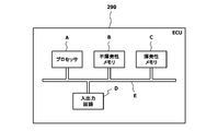
- the power storage device 270 is communicably connected to an electronic control device 290 having a built-in microcomputer via an in-vehicle network 280 such as CAN (Controller Area Network).
- the electronic control device 290 is an example of the control device.
- the electronic control unit 290 includes a processor A such as a CPU (Central Processing Unit), a non-volatile memory B such as a flash ROM (Read Only Memory), and a volatile property such as a RAM (Random Access Memory). It has a memory C, an input / output circuit D that serves as an interface with external devices such as various sensors, and a bus E that connects these devices so that they can communicate with each other.
- a processor A such as a CPU (Central Processing Unit)
- a non-volatile memory B such as a flash ROM (Read Only Memory)
- RAM Random Access Memory
- the electronic control device 290 has output signals from a rotation speed sensor 300 that detects the rotation speed Ne of the diesel engine 100 and an accelerator opening sensor 310 that detects an opening (accelerator opening) ACC of an accelerator pedal (not shown). Have been entered.
- the storage amount SOC State Of Charge
- the rotational speed Ne and the accelerator opening degree ACC can be read from another electronic control device (not shown) connected to be communicable via the in-vehicle network 280.
- the electronic control unit 290 controls the flow path switching valve 190, the power storage device 270, and the fuel injection device 320 based on the rotational speed Ne, the accelerator opening degree ACC, and the storage amount SOC according to the control program stored in the nonvolatile memory B.
- a control signal is output, and the electric supercharger 140, the motor generator 220, and the diesel engine 100 are electronically controlled.
- the torque map shown in FIG. 3 is stored in the non-volatile memory B of the electronic control unit 290.
- the torque map is a map that defines the torque sharing of the engine alone, the electric supercharger 140, and the motor generator 220 according to the engine rotation speed and the required torque.
- the diesel map 100, the electric supercharger 140, and It is set according to the characteristics of motor generator 220 and the like.
- the engine alone includes not the diesel engine 100 alone but the turbocharger 150 integrated therewith.
- the torque sharing region of the diesel engine 100 is referred to as region A
- the torque sharing region of the electric supercharger 140 is referred to as region B
- the torque sharing region of the motor generator 220 is referred to as region C.
- a region D indicates a torque assistable region by the electric supercharger 140
- a region E indicates a torque assistable region by the motor generator 220.
- Region D and region E can be set according to the characteristics of electric supercharger 140, motor generator 220, and power storage device 270, for example.
- the electronic control unit 290 calculates the required torque from the accelerator opening ACC when the diesel engine 100 is in a steady operation state while the vehicle is running, and determines whether the required torque can be achieved by the engine alone. In addition, when it is determined that the required torque can be achieved by the engine alone, the electronic control unit 290 operates at least one of the electric supercharger 140 and the motor generator 220 if the power storage amount SOC of the power storage device 270 has a margin. Assist the engine torque. Furthermore, the electronic control unit 290 reduces the fuel injection amount by the fuel injection device 320 in accordance with the engine torque assist amount.
- the steady operation state of the diesel engine 100 refers to a state where the rotational speed and the required torque of the diesel engine 100 are substantially constant, allowing a slight variation according to the sensor output characteristics.
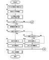
- step 1 the processor A of the electronic control unit 290 reads the accelerator opening ACC from the accelerator opening sensor 310.
- the processor A of the electronic control unit 290 refers to, for example, a map (not shown) in which a required torque corresponding to the accelerator opening is set, and calculates a required torque TDR corresponding to the accelerator opening ACC. .
- the base torque TEB is a torque defined by a thick line dividing the region A and the regions B and C in the torque map shown in FIG. 3, that is, a torque that can be achieved by the engine alone.
- step 4 the processor A of the electronic control unit 290 determines whether or not the torque deviation ⁇ TD is positive, in other words, whether or not the required torque TDR can be achieved by the engine alone. If the processor A of the electronic control unit 290 determines that the torque deviation ⁇ TD is positive, that is, the required torque TDR cannot be achieved by the engine alone, the process proceeds to step 5 (Yes). On the other hand, when the processor A of the electronic control unit 290 determines that the torque deviation ⁇ TD is 0 or negative, that is, the required torque TDR can be achieved by the engine alone, the process proceeds to step 13 (No).
- step 5 the processor A of the electronic control device 290 reads the storage amount SOC from the storage device 270.
- step 6 the processor A of the electronic control unit 290 determines whether or not the storage amount SOC is less than the first predetermined value SOC1.
- the first predetermined value SOC1 is a threshold value for determining whether or not the operation of the electric supercharger 140 and the motor generator 220 is difficult due to a significant decrease in the storage amount SOC of the power storage device 270.
- the power storage capacity of the power storage device 270 and the power consumption of the electric supercharger 140 and the motor generator 220 can be set.
- step 7 If the processor A of the electronic control unit 290 determines that the charged amount SOC is less than the first predetermined value SOC1, the process proceeds to step 7 (Yes). On the other hand, if the processor A of the electronic control unit 290 determines that the charged amount SOC is equal to or greater than the first predetermined value SOC1, the process proceeds to step 9 (No).
- step 7 the processor A of the electronic control device 290 increases the power generation amount of the motor generator 220 and increases the charging current of the power storage device 270 by increasing the fuel injection amount of the fuel injection device 320, for example.
- the processor A of the electronic control device 290 increases the fuel injection amount in accordance with the storage amount SOC of the power storage device 270 and charges the power storage device 270 with the motor generator 220 (the same applies hereinafter).
- step 8 the processor A of the electronic control unit 290 permits the operation of the electric supercharger 140.
- the operation permission or operation prohibition of the electric supercharger 140 can be realized, for example, by changing a permission flag stored in the volatile memory C of the electronic control device 290 (the same applies hereinafter).
- the processor A of the electronic control unit 290 advances the process to step 12.
- step 9 the processor A of the electronic control unit 290 determines whether or not the storage amount SOC is less than the second predetermined value SOC2, in short, the storage amount SOC is equal to or greater than the first predetermined value SOC1 and the second predetermined value SOC2. It is judged whether it is less than.
- second predetermined value SOC2 determines whether or not the amount of stored power SOC of power storage device 270 decreases and electric supercharger 140 can be operated, but the operation of motor generator 220 has become difficult.
- the threshold value can be set in consideration of the power storage capacity of the power storage device 270 and the power consumption of the electric supercharger 140 and the motor generator 220.
- step 10 If the processor A of the electronic control unit 290 determines that the charged amount SOC is less than the second predetermined value SOC2, the process proceeds to step 10 (Yes). On the other hand, if the processor A of the electronic control device 290 determines that the stored amount SOC is equal to or greater than the second predetermined value SOC2, that is, the stored amount SOC of the power storage device 270 is sufficient, the process proceeds to step 11 (No). .
- step 10 the processor A of the electronic control device 290, for example, slightly increases the fuel injection amount of the fuel injection device 320, thereby reducing the power generation amount of the motor generator 220 and reducing the charging current of the power storage device 270. .
- step 11 the processor A of the electronic control unit 290 permits the operation of the electric supercharger 140 and the motor generator 220. Thereafter, the processor A of the electronic control unit 290 advances the process to step 12.
- step 12 the processor A of the electronic control unit 290 executes a subroutine for controlling the electric supercharger 140 and the motor generator 220. Details of this subroutine will be described later.
- step 13 the processor A of the electronic control device 290 reads the storage amount SOC from the storage device 270.
- step 14 the processor A of the electronic control unit 290 determines whether or not the storage amount SOC is less than the first predetermined value SOC1. If the processor A of the electronic control unit 290 determines that the charged amount SOC is less than the first predetermined value SOC1, the process proceeds to step 15 (Yes). On the other hand, if the processor A of the electronic control unit 290 determines that the charged amount SOC is equal to or greater than the first predetermined value SOC1, the process proceeds to step 17 (No).
- processor A of electronic control device 290 increases the charging current of power storage device 270.
- processor A of the electronic control device 290 prohibits the operation of the electric supercharger 140 and the motor generator 220, respectively.
- step 17 the processor A of the electronic control unit 290 determines whether or not the storage amount SOC is less than the second predetermined value SOC2. If the processor A of the electronic control unit 290 determines that the charged amount SOC is less than the second predetermined value SOC2, the process proceeds to step 18 (Yes). On the other hand, if the processor A of the electronic control unit 290 determines that the charged amount SOC is equal to or greater than the second predetermined value SOC2, the process proceeds to step 20 (No).
- processor A of electronic control device 290 reduces the charging current of power storage device 270.
- step 19 the storage amount SOC of the power storage device 270 is decreased, but the torque assist by the electric supercharger 140 is not affected, so the processor A of the electronic control device 290 permits the operation of the electric supercharger 140. To do.
- step 20 since the storage amount SOC of the power storage device 270 is sufficient, the processor A of the electronic control device 290 permits the operation of the electric supercharger 140 and the motor generator 220, respectively. Thereafter, the processor A of the electronic control unit 290 advances the process to step 12.
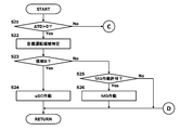
- step 21 the processor A of the electronic control unit 290 determines whether or not the torque deviation ⁇ TD is positive, in other words, whether or not the required torque TDR can be achieved by the engine alone. If the processor A of the electronic control unit 290 determines that the torque deviation ⁇ TD is positive, that is, the required torque TDR cannot be achieved by the engine alone, the process proceeds to step 22 (Yes). On the other hand, when the processor A of the electronic control unit 290 determines that the torque deviation ⁇ TD is 0 or negative, that is, the required torque TDR can be achieved by the engine alone, the process proceeds to step 27 (No).
- the processor A of the electronic control unit 290 refers to the torque map shown in FIG. 3 and specifies a target operation region in which the operating states of the electric supercharger 140 and the motor generator 220 are determined. Specifically, the processor A of the electronic control unit 290 reads the rotational speed Ne from the rotational speed sensor 300 and also reads the accelerator opening ACC from the accelerator opening sensor 310. Then, the processor A of the electronic control unit 290 refers to the torque map and identifies the regions A to C according to the rotational speed Ne and the required torque TDR identified from the accelerator opening ACC. Here, it is not necessary to specify the regions D and E.
- step 23 the processor A of the electronic control unit 290 determines whether or not the target operation area is the area B, that is, whether or not torque assist by the electric supercharger 140 is necessary. If the processor A of the electronic control unit 290 determines that the target operation area is the area B, the process proceeds to step 24 (Yes). On the other hand, if the processor A of the electronic control unit 290 determines that the target operation region is not the region B, that is, the region C where torque assist by the motor generator 220 is necessary, the process proceeds to step 25 (No).
- step 24 the processor A of the electronic control device 290 outputs a control signal to the power storage device 270 to operate the electric supercharger 140 and assists the torque of the diesel engine 100.
- the processor A of the electronic control device 290 can output a control signal corresponding to the magnitude of the torque deviation ⁇ TD to the power storage device 270 and assist only the torque that cannot be achieved by the engine alone. If it does in this way, the power consumption of the electric supercharger 140 can be suppressed. Thereafter, the processor A of the electronic control unit 290 returns the processing to the main routine.
- the processor A of the electronic control unit 290 When the electric supercharger 140 is operated, the processor A of the electronic control unit 290 outputs a control signal to the flow path switching valve 190 to fully close the electric supercharger 140, and the electric supercharger passes all the intake air that has passed through the air cleaner 130. It introduces to the feeder 140 (the same applies below).
- step 25 the processor A of the electronic control device 290 refers to, for example, a permission flag of the volatile memory C, and determines whether or not the operation of the motor generator 220 is permitted. If processor A of electronic control unit 290 determines that operation of motor generator 220 is permitted, the process proceeds to step 26 (Yes). On the other hand, if the processor A of the electronic control unit 290 determines that the operation of the motor generator 220 is not permitted, the process returns to the main routine (No).
- step 26 the processor A of the electronic control device 290 outputs a control signal to the power storage device 270 to operate the motor generator 220 and assists the torque of the diesel engine 100.
- the processor A of the electronic control device 290 can output a control signal corresponding to the magnitude of the torque deviation ⁇ TD to the power storage device 270 and assist only the torque that cannot be achieved by the engine alone. In this way, the power consumption of motor generator 220 can be suppressed.
- the processor A of the electronic control unit 290 returns the processing to the main routine.
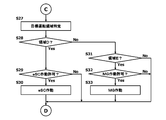
- step 27 the processor A of the electronic control unit 290 specifies the target operation region through the same processing as in step 22.
- the processor A of the electronic control unit 290 determines whether or not the target operation area is the area D, in other words, whether or not torque assist by the electric supercharger 140 is possible. If the processor A of the electronic control unit 290 determines that the target operation area is the area D, the process proceeds to step 29 (Yes). On the other hand, if the processor A of the electronic control unit 290 determines that the target operation area is not the area D, the process proceeds to step 31 (No).
- step 29 the processor A of the electronic control unit 290 refers to, for example, the permission flag of the volatile memory C and determines whether or not the operation of the electric supercharger 140 is permitted. If the processor A of the electronic control unit 290 determines that the operation of the electric supercharger 140 is permitted, the process proceeds to step 30 (Yes). On the other hand, if the processor A of the electronic control unit 290 determines that the operation of the electric supercharger 140 is not permitted, the process returns to the main routine (No).
- step 30 the processor A of the electronic control device 290 outputs a control signal to the power storage device 270 to operate the electric supercharger 140 and assists the torque of the diesel engine 100.
- the processor A of the electronic control device 290 can assist the torque by outputting a control signal corresponding to a deviation obtained by subtracting the torque defining the lower limit of the region D from the required torque TDR to the power storage device 270. Thereafter, the processor A of the electronic control unit 290 returns the processing to the main routine.
- step 31 the processor A of the electronic control unit 290 determines whether or not the target operation area is the area E, that is, whether or not torque assist by the motor generator 220 is possible. If the processor A of the electronic control unit 290 determines that the target operation area is the area E, the process proceeds to step 32 (Yes). On the other hand, if the processor A of the electronic control unit 290 determines that the target operation area is not the area E, the process returns to the main routine (No).
- step 32 the processor A of the electronic control device 290 determines whether or not the operation of the motor generator 220 is permitted with reference to the permission flag of the volatile memory C, for example. If the processor A of the electronic control unit 290 determines that the operation of the motor generator 220 is permitted, the process proceeds to step 33 (Yes). On the other hand, if the processor A of the electronic control unit 290 determines that the operation of the motor generator 220 is not permitted, the process returns to the main routine (No).
- step 33 the processor A of the electronic control device 290 outputs a control signal to the power storage device 270 to operate the motor generator 220 and assists the torque of the diesel engine 100.
- the processor A of the electronic control device 290 can output a control signal corresponding to a deviation obtained by subtracting the torque defining the lower limit of the region E from the required torque TDR to assist the torque. Thereafter, the processor A of the electronic control unit 290 returns the processing to the main routine.
- the processor A of the electronic control unit 290 calculates the required torque TDR from the accelerator opening ACC, and subtracts the base torque TEB from the required torque TDR. Find ⁇ TD.
- the processor A of the electronic control device 290 controls the charging of the power storage device 270 and the electric overload according to the power storage amount SOC of the power storage device 270.
- the operation permission control for the feeder 140 and the motor generator 220 is executed.
- the processor A of the electronic control unit 290 increases the fuel injection amount to increase the power generation amount of the motor generator 220, and the electric supercharger 140 operations are allowed.
- the processor A of the electronic control unit 290 slightly increases the fuel injection amount and slightly increases the power generation amount of the motor generator 220. The operation of the electric supercharger 140 and the motor generator 220 is permitted.
- the processor A of the electronic control device 290 permits the operation of the electric supercharger 140 and the motor generator 220 without charging the power storage device 270, respectively. .
- the processor A of the electronic control device 290 controls the charging of the power storage device 270 according to the power storage amount SOC of the power storage device 270, In addition, the operation permission control of the electric supercharger 140 and the motor generator 220 is executed.
- the processor A of the electronic control unit 290 increases the fuel injection amount to increase the power generation amount of the motor generator 220, and the electric supercharger 140 and the operation of the motor generator 220 are prohibited.
- the processor A of the electronic control unit 290 slightly increases the fuel injection amount and slightly increases the power generation amount of the motor generator 220. The operation of the electric supercharger 140 is permitted.
- the processor A of the electronic control device 290 permits the operation of the electric supercharger 140 and the motor generator 220 without charging the power storage device 270, respectively. .
- the processor A of the electronic control unit 290 determines that the target operation region specified from the rotational speed Ne and the required torque TDR is the region B, that is, the torque assist by the electric supercharger 140. If it is a necessary area, the electric supercharger 140 is operated to assist the torque. Further, the processor A of the electronic control unit 290 allows the motor to operate only when the operation of the motor generator 220 is permitted if the target operation region is not the region B, that is, if the torque assist by the motor generator 220 is necessary. The generator 220 is operated to assist the torque. At this time, since the charging control of the power storage device 270 is performed at the same time, there is no shortage of power for operating the electric supercharger 140.
- the processor A of the electronic control unit 290 performs the electric supercharging. Only when the operation of the machine 140 is permitted, the electric supercharger 140 is operated to assist the torque. Further, if the target operation region is region E, that is, a region where torque assist by the motor generator 220 is possible, the processor A of the electronic control device 290 only allows the motor generator 220 to operate. Actuate 220 to assist torque.
- the electric supercharger 140 or the motor generator 220 is operated to assist the engine torque.
- the fuel injection amount is reduced by that amount, so that the fuel efficiency of the hybrid system can be further improved.
- the power storage device 270 is charged with the power storage device 270 by using the appropriate charge during traveling according to the power storage amount SOC without relying only on energy regeneration such as a brake. For this reason, it is not necessary to increase the storage capacity of the power storage device 270, and the power storage device 270 can be reduced. If the power storage device 270 is made smaller, its weight is reduced. For example, it is possible to improve exercise performance and the like through a reduction in vehicle weight. It should be noted that during running charging, a driving range where the fuel consumption rate is low and the engine load is low is applied to the motor generator 220 and converted into electric energy, so that the fuel efficiency can be improved comprehensively.
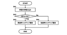
- a low speed torque map used when the vehicle speed is less than a predetermined value a vehicle speed And a high-speed torque map used when is equal to or greater than a predetermined value.
- the torque map corresponding to the vehicle speed is not limited to two for low speed and high speed, and a plurality of torque maps corresponding to the vehicle speed may be used.
- the vehicle speed VSP is inputted to the electronic control device 290 from a vehicle speed sensor (not shown) or another electronic control device.
- FIG. 9 shows an example of a torque map selection process that is repeatedly executed by the processor A of the electronic control unit 290 every predetermined time t2 when the diesel engine 100 shifts to a steady operation state while the vehicle is running.
- the predetermined time t2 may be the same as or different from the predetermined time t1.
- step 41 the processor A of the electronic control unit 290 reads the vehicle speed VSP from the vehicle speed sensor or another electronic control unit.
- step 42 the processor A of the electronic control unit 290 determines whether or not the vehicle speed VSP is equal to or higher than a predetermined value Vth.
- the predetermined value Vth is a threshold value for determining whether or not the vehicle is traveling at a low speed, and can be set in consideration of the characteristics of the electric supercharger 140, for example. If the processor A of the electronic control unit 290 determines that the vehicle speed VSP is equal to or higher than the predetermined value Vth, that is, the vehicle is traveling at a high speed, the process proceeds to step 43 (Yes). On the other hand, if the processor A of the electronic control unit 290 determines that the vehicle speed VSP is less than the predetermined value Vth, that is, the vehicle is traveling at a low speed, the process proceeds to step 44 (No).
- step 43 the processor A of the electronic control unit 290 selects a high-speed torque map.
- step 44 the processor A of the electronic control unit 290 selects a low speed torque map.
- FIG. 10 shows another example of the main routine of the control program that is executed instead of the main routine shown in FIG.
- the description shall be simplified for the purpose of avoiding duplication description (hereinafter the same).
- step 51 the processor A of the electronic control device 290 reads the storage amount SOC from the storage device 270.
- step 52 the processor A of the electronic control unit 290 determines whether or not the charged amount SOC is less than the first predetermined value SOC1.
- the first predetermined value SOC1 is a threshold value for determining whether or not the remaining storage amount SOC of the power storage device 270 has decreased, and may be set according to the storage capacity of the power storage device 270, for example. it can. If the processor A of the electronic control unit 290 determines that the charged amount SOC is less than the first predetermined value SOC1, the process proceeds to step 53 (Yes). On the other hand, if the processor A of the electronic control unit 290 determines that the charged amount SOC is equal to or greater than the first predetermined value SOC1, the process proceeds to step 55 (No).
- step 53 processor A of electronic control device 290 increases the charging current of power storage device 270.
- step 54 the processor A of the electronic control unit 290 prohibits the operation of the electric supercharger 140 and the motor generator 220, respectively.
- step 55 the processor A of the electronic control unit 290 determines whether or not the storage amount SOC is less than the second predetermined value SOC2, that is, the storage amount SOC is equal to or more than the first predetermined value SOC1 and the second predetermined value SOC2. It is judged whether it is less than.
- the second predetermined value SOC2 is a threshold value for determining whether or not the operation of the electric supercharger 140 and the motor generator 220 is difficult because the storage amount SOC of the power storage device 270 has significantly decreased.
- the power storage capacity of the power storage device 270 and the power consumption of the electric supercharger 140 and the motor generator 220 can be set.
- step 56 If the processor A of the electronic control unit 290 determines that the charged amount SOC is less than the second predetermined value SOC2, the process proceeds to step 56 (Yes). On the other hand, if the processor A of the electronic control unit 290 determines that the charged amount SOC is equal to or greater than the second predetermined value SOC2, the process proceeds to step 58 (No).
- step 56 the processor A of the electronic control unit 290 sets the charging current of the power storage device 270 to the middle level, that is, an intermediate value between the large charging current and the small charging current.
- step 57 the processor A of the electronic control unit 290 permits the operation of the electric supercharger 140.
- step 58 the processor A of the electronic control unit 290 determines whether or not the storage amount SOC is less than the third predetermined value SOC3.
- the storage amount SOC is greater than or equal to the second predetermined value SOC2 and the third predetermined value SOC3. It is judged whether it is less than.
- third predetermined value SOC3 determines whether or not the amount of stored power SOC of power storage device 270 decreases and electric supercharger 140 can be operated, but the operation of motor generator 220 has become difficult.
- the threshold value can be set in consideration of the power storage capacity of the power storage device 270 and the power consumption of the electric supercharger 140 and the motor generator 220.
- step 59 If the processor A of the electronic control unit 290 determines that the charged amount SOC is less than the third predetermined value SOC3, the process proceeds to step 59 (Yes). On the other hand, if the processor A of the electronic control unit 290 determines that the charged amount SOC is equal to or greater than the third predetermined value SOC3, the process proceeds to step 61 (No).
- step 59 processor A of electronic control device 290 decreases the charging current of power storage device 270.
- step 60 processor A of electronic control unit 290 permits operation of motor generator 220.
- step 61 since the storage amount SOC of the power storage device 270 is sufficient, the processor A of the electronic control device 290 permits the operation of the electric supercharger 140 and the motor generator 220, respectively.
- the charging of the power storage device 270 and the operation permission of the electric supercharger 140 and the motor generator 220 are performed in detail as compared with the previous embodiment. Further, as the storage amount SOC of power storage device 270 increases, operation of electric supercharger 140, motor generator 220, electric supercharger 140, and motor generator 220 is sequentially permitted. For this reason, it can contribute to the fuel consumption improvement of a hybrid system. Note that the charging control illustrated in FIG. 10 is performed in four stages according to the storage amount SOC of the power storage device 270, but may be performed in five stages or more.
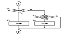
- FIG. 11 shows another example of the subroutine of the control program that is executed instead of the subroutine shown in FIG.
- step 71 the processor A of the electronic control unit 290 refers to the permission flag of the volatile memory C and determines whether or not the operation of the motor generator 220 is permitted. If processor A of electronic control unit 290 determines that operation of motor generator 220 is permitted, the process proceeds to step 72 (Yes). On the other hand, if processor A of electronic control unit 290 determines that operation of motor generator 220 is not permitted, the process proceeds to step 73 (No).
- step 72 the processor A of the electronic control device 290 outputs a control signal to the power storage device 270 to operate the motor generator 220 and assist the torque of the diesel engine 100.
- step 73 the processor A of the electronic control unit 290 refers to the permission flag in the volatile memory C and determines whether or not the operation of the electric supercharger 140 is permitted. If the processor A of the electronic control unit 290 determines that the operation of the electric supercharger 140 is permitted, the process proceeds to step 74 (Yes). On the other hand, if the processor A of the electronic control unit 290 determines that the operation of the electric supercharger 140 is not permitted, the process returns to the main routine (No).
- step 74 the processor A of the electronic control device 290 outputs a control signal to the power storage device 270 to operate the electric supercharger 140 and assists the torque of the diesel engine 100.
- torque may be assisted using both electric supercharger 140 and motor generator 220.
- the torque can be assisted by at least one of the electric supercharger 140 and the motor generator 220 if the power storage amount SOC of the power storage device 270 has a margin.
- the hybrid system engine may not be equipped with the turbocharger 150 that is driven to rotate by exhaust energy.
- the engine unit is only the diesel engine 100.
Abstract
Description
図1は、トラックなどの車両に搭載された、ハイブリッドシステムの一例を示す。 Hereinafter, embodiments for carrying out the present invention will be described in detail with reference to the accompanying drawings.
FIG. 1 shows an example of a hybrid system mounted on a vehicle such as a truck.
ステップ2では、電子制御装置290のプロセッサAが、例えば、アクセル開度に対応した要求トルクが設定されたマップ(図示せず)を参照し、アクセル開度ACCに応じた要求トルクTDRを算出する。 In step 1 (abbreviated as “S1” in the figure, the same applies hereinafter), the processor A of the
In step 2, the processor A of the
ステップ6では、電子制御装置290のプロセッサAが、蓄電量SOCが第1の所定値SOC1未満であるか否かを判定する。ここで、第1の所定値SOC1は、蓄電装置270の蓄電量SOCが大幅に低下し、電動過給機140及びモータジェネレータ220の作動が困難となったか否かを判定するための閾値であって、例えば、蓄電装置270の蓄電容量並びに電動過給機140及びモータジェネレータ220の消費電力を考慮して設定することができる。そして、電子制御装置290のプロセッサAは、蓄電量SOCが第1の所定値SOC1未満であると判定すれば、処理をステップ7へと進める(Yes)。一方、電子制御装置290のプロセッサAは、蓄電量SOCが第1の所定値SOC1以上であると判定すれば、処理をステップ9へと進める(No)。 In
In step 6, the processor A of the
ステップ14では、電子制御装置290のプロセッサAが、蓄電量SOCが第1の所定値SOC1未満であるか否かを判定する。そして、電子制御装置290のプロセッサAは、蓄電量SOCが第1の所定値SOC1未満であると判定すれば、処理をステップ15へと進める(Yes)。一方、電子制御装置290のプロセッサAは、蓄電量SOCが第1の所定値SOC1以上であると判定すれば、処理をステップ17へと進める(No)。 In step 13, the processor A of the
In step 14, the processor A of the
ステップ16では、蓄電装置270の蓄電量SOCが少なくなっているため、電子制御装置290のプロセッサAが、電動過給機140及びモータジェネレータ220の作動を夫々禁止する。 In step 15, processor A of
In step 16, since the storage amount SOC of the
ステップ19では、蓄電装置270の蓄電量SOCが低下しているが、電動過給機140によるトルクアシストに影響がないため、電子制御装置290のプロセッサAが、電動過給機140の作動を許可する。 In step 18, processor A of
In step 19, the storage amount SOC of the
ステップ21では、電子制御装置290のプロセッサAが、トルク偏差ΔTDが正であるか否か、要するに、エンジン単体で要求トルクTDRを達成できるか否かを判定する。そして、電子制御装置290のプロセッサAは、トルク偏差ΔTDが正、即ち、エンジン単体で要求トルクTDRを達成できないと判定すれば、処理をステップ22へと進める(Yes)。一方、電子制御装置290のプロセッサAは、トルク偏差ΔTDが0又は負、即ち、エンジン単体で要求トルクTDRを達成できると判定すれば、処理をステップ27へと進める(No)。 6 and 7 show an example of a subroutine for controlling the
In step 21, the processor A of the
ステップ28では、電子制御装置290のプロセッサAが、目標運転領域が領域Dであるか否か、要するに、電動過給機140によるトルクアシストが可能であるか否かを判定する。そして、電子制御装置290のプロセッサAは、目標運転領域が領域Dであると判定すれば、処理をステップ29へと進める(Yes)。一方、電子制御装置290のプロセッサAは、目標運転領域が領域Dでないと判定すれば、処理をステップ31へと進める(No)。 In step 27, the processor A of the
In step 28, the processor A of the
ステップ42では、電子制御装置290のプロセッサAが、車速VSPが所定値Vth以上であるか否かを判定する。ここで、所定値Vthは、車両が低速で走行しているか否かを判定するための閾値であって、例えば、電動過給機140の特性などを考慮して設定することができる。そして、電子制御装置290のプロセッサAは、車速VSPが所定値Vth以上、即ち、車両が高速で走行していると判定すれば、処理をステップ43へと進める(Yes)。一方、電子制御装置290のプロセッサAは、車速VSPが所定値Vth未満、即ち、車両が低速で走行していると判定すれば、処理をステップ44へと進める(No)。 In step 41, the processor A of the
In step 42, the processor A of the
ステップ44では、電子制御装置290のプロセッサAが、低速用トルクマップを選定する。 In step 43, the processor A of the
In step 44, the processor A of the
ステップ52では、電子制御装置290のプロセッサAが、蓄電量SOCが第1の所定値SOC1未満であるか否かを判定する。ここで、第1の所定値SOC1は、蓄電装置270の蓄電量SOCが残り少なくなったか否かを判定するための閾値であって、例えば、蓄電装置270の蓄電容量などに応じて設定することができる。そして、電子制御装置290のプロセッサAは、蓄電量SOCが第1の所定値SOC1未満であると判定すれば、処理をステップ53へと進める(Yes)。一方、電子制御装置290のプロセッサAは、蓄電量SOCが第1の所定値SOC1以上であると判定すれば、処理をステップ55へと進める(No)。 In step 51, the processor A of the
In step 52, the processor A of the
ステップ54では、電子制御装置290のプロセッサAが、電動過給機140及びモータジェネレータ220の作動を夫々禁止する。 In step 53, processor A of
In
ステップ57では、電子制御装置290のプロセッサAが、電動過給機140の作動を許可する。 In
In
ステップ60では、電子制御装置290のプロセッサAが、モータジェネレータ220の作動を許可する。 In
In step 60, processor A of
140 電動過給機
220 モータジェネレータ
270 蓄電装置
290 電子制御装置(制御装置)
320 燃料噴射装置 100 diesel engine (engine)
140
320 Fuel injector
Claims (12)
- 電動過給機、モータジェネレータ及びこれらに電力を供給する蓄電装置を備え、要求トルクに応じて前記電動過給機及び前記モータジェネレータを制御するハイブリッドシステムの制御装置であって、
前記制御装置は、エンジン単体で要求トルクを達成できる場合であっても、前記蓄電装置の蓄電量に余裕があれば、前記電動過給機及び前記モータジェネレータの少なくとも一方を作動させてエンジントルクをアシストするように構成された、
ことを特徴とするハイブリッドシステムの制御装置。 An electric supercharger, a motor generator, and a power storage device that supplies electric power to these, a control device of a hybrid system that controls the electric supercharger and the motor generator according to a required torque,
Even when the required torque can be achieved by the engine alone, the control device operates the electric supercharger or the motor generator to increase the engine torque if the power storage amount of the power storage device is sufficient. Configured to assist,
A control device of a hybrid system characterized by the above. - 前記制御装置は、定常運転時にエンジントルクをアシストするように構成された、
ことを特徴とする請求項1に記載のハイブリッドシステムの制御装置。 The control device is configured to assist engine torque during steady operation.
The control device for a hybrid system according to claim 1. - 前記制御装置は、前記蓄電装置の蓄電量が増加するにつれて、前記電動過給機、前記モータジェネレータ、前記電動過給機及び前記モータジェネレータの作動を順次許可するように構成された、
ことを特徴とする請求項1又は請求項2に記載のハイブリッドシステムの制御装置。 The control device is configured to sequentially permit the operation of the electric supercharger, the motor generator, the electric supercharger, and the motor generator as the amount of power stored in the power storage device increases.
The control apparatus for a hybrid system according to claim 1 or 2, characterized in that - 前記制御装置は、車速に応じて、前記電動過給機の作動領域を変更するように構成された、
ことを特徴とする請求項1~請求項3のいずれか1つに記載のハイブリッドシステムの制御装置。 The control device is configured to change an operation region of the electric supercharger according to a vehicle speed.
4. The hybrid system control device according to claim 1, wherein the control device is a hybrid system control device. - 前記制御装置は、前記電動過給機及び前記モータジェネレータの少なくとも一方を作動させてエンジントルクをアシストするとき、当該アシスト量に応じてエンジンの燃料噴射量を低減するように構成された、
ことを特徴とする請求項1~請求項4のいずれか1つに記載のハイブリッドシステムの制御装置。 The control device is configured to reduce the fuel injection amount of the engine according to the assist amount when operating the engine torque by operating at least one of the electric supercharger and the motor generator.
5. The hybrid system control device according to claim 1, wherein the control device is a hybrid system control device. - 前記制御装置は、前記蓄電装置の蓄電量に応じて燃料噴射量を増量し、前記モータジェネレータで前記蓄電装置を充電するように構成された、
ことを特徴とする請求項1~請求項5のいずれか1つに記載のハイブリッドシステムの制御装置。 The control device is configured to increase a fuel injection amount in accordance with a storage amount of the power storage device, and to charge the power storage device with the motor generator.
6. The hybrid system control device according to claim 1, wherein the control device is a hybrid system control device. - 電動過給機、モータジェネレータ及びこれらに電力を供給する蓄電装置を備え、要求トルクに応じて前記電動過給機及び前記モータジェネレータを制御するハイブリッドシステムの制御装置が、
前記エンジン単体で要求トルクを達成できると判定した場合であっても、前記蓄電装置の蓄電量に余裕があれば、前記電動過給機及び前記モータジェネレータの少なくとも一方を作動させてエンジントルクをアシストする、
ことを特徴とするハイブリッドシステムの制御方法。 An electric supercharger, a motor generator, and a power storage device that supplies electric power to these, and a control device of a hybrid system that controls the electric supercharger and the motor generator according to a required torque,
Even when it is determined that the required torque can be achieved by the engine alone, if the power storage amount of the power storage device is sufficient, at least one of the electric supercharger and the motor generator is operated to assist the engine torque. To
A control method of a hybrid system characterized by the above. - 前記制御装置が、定常運転時にエンジントルクをアシストする、
ことを特徴とする請求項7に記載のハイブリッドシステムの制御方法。 The control device assists engine torque during steady operation;
The method of controlling a hybrid system according to claim 7. - 前記制御装置が、前記蓄電装置の蓄電量が増加するにつれて、前記電動過給機、前記モータジェネレータ、前記電動過給機及び前記モータジェネレータの作動を順次許可する、
ことを特徴とする請求項7又は請求項8に記載のハイブリッドシステムの制御方法。 The control device sequentially permits the operation of the electric supercharger, the motor generator, the electric supercharger, and the motor generator as the amount of power stored in the power storage device increases.
The method for controlling a hybrid system according to claim 7 or 8, wherein - 前記制御装置が、車速に応じて、前記電動過給機の作動領域を変更する、
ことを特徴とする請求項7~請求項9のいずれか1つに記載のハイブリッドシステムの制御方法。 The control device changes an operating region of the electric supercharger according to a vehicle speed;
10. The method for controlling a hybrid system according to any one of claims 7 to 9, wherein: - 前記制御装置が、前記電動過給機及び前記モータジェネレータの少なくとも一方を作動させてエンジントルクをアシストするとき、当該アシスト量に応じてエンジンの燃料噴射量を低減する、
ことを特徴とする請求項7~請求項10のいずれか1つに記載のハイブリッドシステムの制御方法。 When the control device activates at least one of the electric supercharger and the motor generator to assist engine torque, the fuel injection amount of the engine is reduced according to the assist amount;
The method for controlling a hybrid system according to any one of claims 7 to 10, wherein: - 前記制御装置が、前記蓄電装置の蓄電量に応じて燃料噴射量を増量し、前記モータジェネレータで前記蓄電装置を充電する、
ことを特徴とする請求項7~請求項11のいずれか1つに記載のハイブリッドシステムの制御方法。 The control device increases a fuel injection amount in accordance with a storage amount of the power storage device, and charges the power storage device with the motor generator;
The method for controlling a hybrid system according to any one of claims 7 to 11, wherein:
Priority Applications (5)
| Application Number | Priority Date | Filing Date | Title |
|---|---|---|---|
| US16/060,970 US10974584B2 (en) | 2015-12-11 | 2015-12-16 | Device and method for controlling hybrid system |
| JP2017555935A JP6741686B2 (en) | 2015-12-16 | 2015-12-16 | Hybrid system control device and control method |
| EP15910723.4A EP3392108B1 (en) | 2015-12-16 | 2015-12-16 | Controller and method for controlling hybrid system |
| PCT/JP2015/085293 WO2017104033A1 (en) | 2015-12-16 | 2015-12-16 | Device and method for controlling hybrid system |
| CN201580085401.4A CN108430846B8 (en) | 2015-12-16 | 2015-12-16 | Control device and control method for hybrid power system |
Applications Claiming Priority (1)
| Application Number | Priority Date | Filing Date | Title |
|---|---|---|---|
| PCT/JP2015/085293 WO2017104033A1 (en) | 2015-12-16 | 2015-12-16 | Device and method for controlling hybrid system |
Publications (1)
| Publication Number | Publication Date |
|---|---|
| WO2017104033A1 true WO2017104033A1 (en) | 2017-06-22 |
Family
ID=59056228
Family Applications (1)
| Application Number | Title | Priority Date | Filing Date |
|---|---|---|---|
| PCT/JP2015/085293 WO2017104033A1 (en) | 2015-12-11 | 2015-12-16 | Device and method for controlling hybrid system |
Country Status (4)
| Country | Link |
|---|---|
| EP (1) | EP3392108B1 (en) |
| JP (1) | JP6741686B2 (en) |
| CN (1) | CN108430846B8 (en) |
| WO (1) | WO2017104033A1 (en) |
Cited By (2)
| Publication number | Priority date | Publication date | Assignee | Title |
|---|---|---|---|---|
| CN110239517A (en) * | 2018-03-08 | 2019-09-17 | 丰田自动车株式会社 | Hybrid vehicle |
| WO2020013251A1 (en) * | 2018-07-13 | 2020-01-16 | 日野自動車株式会社 | Motor control device |
Families Citing this family (1)
| Publication number | Priority date | Publication date | Assignee | Title |
|---|---|---|---|---|
| KR20210074431A (en) * | 2019-12-11 | 2021-06-22 | 현대자동차주식회사 | Apparatus for controlling hybrid vehciel having electric supercharger and method using the same |
Citations (9)
| Publication number | Priority date | Publication date | Assignee | Title |
|---|---|---|---|---|
| JPH11332015A (en) * | 1998-05-18 | 1999-11-30 | Hitachi Ltd | Hybrid vehicle driving apparatus and method therefor |
| JP2004076687A (en) * | 2002-08-21 | 2004-03-11 | Toyota Motor Corp | Exhaust/electric supercharging type hybrid vehicle |
| JP2005171842A (en) | 2003-12-10 | 2005-06-30 | Mazda Motor Corp | Control device of power train equipped with electric supercharger |
| JP2005240580A (en) * | 2004-02-24 | 2005-09-08 | Toyota Motor Corp | Hybrid vehicle and its control method |
| JP2005330818A (en) * | 2004-05-18 | 2005-12-02 | Mazda Motor Corp | Control device for power train equipped with electric supercharger |
| JP2005337176A (en) * | 2004-05-28 | 2005-12-08 | Toyota Motor Corp | Control method for restraining filter from clogging in diesel hybrid vehicle |
| GB2456841A (en) * | 2008-01-16 | 2009-07-29 | Thomas Tsoi Hei Ma | Supercharger air hybrid vehicle |
| JP2013181393A (en) * | 2012-02-29 | 2013-09-12 | Daimler Ag | Supercharging system for engine |
| JP2015514624A (en) * | 2012-03-29 | 2015-05-21 | イートン コーポレーションEaton Corporation | Electric energy generation using a variable speed hybrid electric supercharger assembly |
Family Cites Families (7)
| Publication number | Priority date | Publication date | Assignee | Title |
|---|---|---|---|---|
| JP3922105B2 (en) * | 2002-02-06 | 2007-05-30 | 株式会社デンソー | Engine composite rotating electric machine |
| EP1749990B1 (en) * | 2005-08-03 | 2013-07-03 | Honda Motor Co., Ltd. | An engine system with a supercharger |
| DE102008035451A1 (en) * | 2008-07-30 | 2009-03-19 | Daimler Ag | Hybrid drive optimizing method for hybrid vehicle, involves controlling power output or power input of electric motor such that power output of engine is controlled on load points, which are optimal for engine operating condition |
| DE102012004394A1 (en) * | 2012-03-03 | 2013-09-05 | Daimler Ag | Method for operating drive device for motor vehicle, involves assigning electric machine to output shaft, where another electric machine is associated to exhaust gas turbo charger and is electrically connected with former electric machine |
| WO2014165233A1 (en) * | 2013-03-12 | 2014-10-09 | Eaton Corporation | Adaptive state of charge regulation and control of variable speed hybrid electric supercharger assembly for efficient vehicle operation |
| WO2014161558A1 (en) * | 2013-04-05 | 2014-10-09 | Volvo Truck Corporation | Method and apparatus for controlling an engine with egr and a turbocharger |
| FR3025833B1 (en) * | 2014-09-15 | 2017-12-29 | Renault Sas | POWERTRAIN COMPRISING AN ELECTRIC COMPRESSOR AND METHOD FOR CONTROLLING THE POWERTRAIN GROUP |
-
2015
- 2015-12-16 JP JP2017555935A patent/JP6741686B2/en active Active
- 2015-12-16 WO PCT/JP2015/085293 patent/WO2017104033A1/en active Application Filing
- 2015-12-16 EP EP15910723.4A patent/EP3392108B1/en active Active
- 2015-12-16 CN CN201580085401.4A patent/CN108430846B8/en not_active Expired - Fee Related
Patent Citations (9)
| Publication number | Priority date | Publication date | Assignee | Title |
|---|---|---|---|---|
| JPH11332015A (en) * | 1998-05-18 | 1999-11-30 | Hitachi Ltd | Hybrid vehicle driving apparatus and method therefor |
| JP2004076687A (en) * | 2002-08-21 | 2004-03-11 | Toyota Motor Corp | Exhaust/electric supercharging type hybrid vehicle |
| JP2005171842A (en) | 2003-12-10 | 2005-06-30 | Mazda Motor Corp | Control device of power train equipped with electric supercharger |
| JP2005240580A (en) * | 2004-02-24 | 2005-09-08 | Toyota Motor Corp | Hybrid vehicle and its control method |
| JP2005330818A (en) * | 2004-05-18 | 2005-12-02 | Mazda Motor Corp | Control device for power train equipped with electric supercharger |
| JP2005337176A (en) * | 2004-05-28 | 2005-12-08 | Toyota Motor Corp | Control method for restraining filter from clogging in diesel hybrid vehicle |
| GB2456841A (en) * | 2008-01-16 | 2009-07-29 | Thomas Tsoi Hei Ma | Supercharger air hybrid vehicle |
| JP2013181393A (en) * | 2012-02-29 | 2013-09-12 | Daimler Ag | Supercharging system for engine |
| JP2015514624A (en) * | 2012-03-29 | 2015-05-21 | イートン コーポレーションEaton Corporation | Electric energy generation using a variable speed hybrid electric supercharger assembly |
Cited By (7)
| Publication number | Priority date | Publication date | Assignee | Title |
|---|---|---|---|---|
| CN110239517A (en) * | 2018-03-08 | 2019-09-17 | 丰田自动车株式会社 | Hybrid vehicle |
| JP2019155995A (en) * | 2018-03-08 | 2019-09-19 | トヨタ自動車株式会社 | Hybrid vehicle |
| US11358583B2 (en) | 2018-03-08 | 2022-06-14 | Toyota Jidosha Kabushiki Kaisha | Hybrid vehicle |
| WO2020013251A1 (en) * | 2018-07-13 | 2020-01-16 | 日野自動車株式会社 | Motor control device |
| JP2020011530A (en) * | 2018-07-13 | 2020-01-23 | 日野自動車株式会社 | Motor control device |
| JP7122186B2 (en) | 2018-07-13 | 2022-08-19 | 日野自動車株式会社 | motor controller |
| US11827209B2 (en) | 2018-07-13 | 2023-11-28 | Hino Motors, Ltd. | Motor control device |
Also Published As
| Publication number | Publication date |
|---|---|
| EP3392108B1 (en) | 2020-10-07 |
| JPWO2017104033A1 (en) | 2018-11-08 |
| EP3392108A4 (en) | 2019-09-11 |
| CN108430846A (en) | 2018-08-21 |
| CN108430846B8 (en) | 2021-11-19 |
| EP3392108A1 (en) | 2018-10-24 |
| JP6741686B2 (en) | 2020-08-19 |
| CN108430846B (en) | 2021-10-22 |
Similar Documents
| Publication | Publication Date | Title |
|---|---|---|
| US10974584B2 (en) | Device and method for controlling hybrid system | |
| US7610124B2 (en) | Control device for motor-driven vehicle | |
| JP4535184B2 (en) | Control device for hybrid vehicle | |
| JP2011239605A (en) | Controller of vehicle | |
| JP7167783B2 (en) | hybrid vehicle | |
| US11472399B2 (en) | Controller and control method for hybrid vehicle | |
| WO2017104033A1 (en) | Device and method for controlling hybrid system | |
| JP2015147430A (en) | vehicle control device | |
| CN111749805B (en) | Hybrid vehicle and engine control method for hybrid vehicle | |
| JP7196738B2 (en) | hybrid vehicle | |
| JP7143811B2 (en) | vehicle | |
| US20200361470A1 (en) | Hybrid vehicle and method of controlling hybrid vehicle | |
| JP7180482B2 (en) | hybrid vehicle | |
| JP7088088B2 (en) | Hybrid vehicle and hybrid vehicle control method | |
| JP7196715B2 (en) | Hybrid vehicle and hybrid vehicle control method | |
| JP2020192839A (en) | vehicle | |
| JP2020185862A (en) | Hybrid vehicle | |
| JP7192634B2 (en) | Hybrid vehicle and hybrid vehicle control method | |
| JP3551170B2 (en) | Control of diesel hybrid vehicles | |
| JP7183928B2 (en) | vehicle | |
| JP7103290B2 (en) | Hybrid vehicle and hybrid vehicle control method | |
| JP2023080623A (en) | vehicle | |
| JP2015123832A (en) | Vehicle control apparatus | |
| JP2020192840A (en) | Hybrid vehicle | |
| JP2017114418A (en) | Hybrid automobile |
Legal Events
| Date | Code | Title | Description |
|---|---|---|---|
| 121 | Ep: the epo has been informed by wipo that ep was designated in this application |
Ref document number: 15910723 Country of ref document: EP Kind code of ref document: A1 |
|
| ENP | Entry into the national phase |
Ref document number: 2017555935 Country of ref document: JP Kind code of ref document: A |
|
| NENP | Non-entry into the national phase |
Ref country code: DE |
|
| WWE | Wipo information: entry into national phase |
Ref document number: 2015910723 Country of ref document: EP |
|
| ENP | Entry into the national phase |
Ref document number: 2015910723 Country of ref document: EP Effective date: 20180716 |