WO2017101835A1 - 电动汽车及其车载充电器和车载充电器的控制方法 - Google Patents
电动汽车及其车载充电器和车载充电器的控制方法 Download PDFInfo
- Publication number
- WO2017101835A1 WO2017101835A1 PCT/CN2016/110268 CN2016110268W WO2017101835A1 WO 2017101835 A1 WO2017101835 A1 WO 2017101835A1 CN 2016110268 W CN2016110268 W CN 2016110268W WO 2017101835 A1 WO2017101835 A1 WO 2017101835A1
- Authority
- WO
- WIPO (PCT)
- Prior art keywords
- switch tube
- bridge
- time
- mode
- controlled
- Prior art date
- Legal status (The legal status is an assumption and is not a legal conclusion. Google has not performed a legal analysis and makes no representation as to the accuracy of the status listed.)
- Ceased
Links
Images


Classifications
-
- B—PERFORMING OPERATIONS; TRANSPORTING
- B60—VEHICLES IN GENERAL
- B60L—PROPULSION OF ELECTRICALLY-PROPELLED VEHICLES; SUPPLYING ELECTRIC POWER FOR AUXILIARY EQUIPMENT OF ELECTRICALLY-PROPELLED VEHICLES; ELECTRODYNAMIC BRAKE SYSTEMS FOR VEHICLES IN GENERAL; MAGNETIC SUSPENSION OR LEVITATION FOR VEHICLES; MONITORING OPERATING VARIABLES OF ELECTRICALLY-PROPELLED VEHICLES; ELECTRIC SAFETY DEVICES FOR ELECTRICALLY-PROPELLED VEHICLES
- B60L50/00—Electric propulsion with power supplied within the vehicle
- B60L50/50—Electric propulsion with power supplied within the vehicle using propulsion power supplied by batteries or fuel cells
- B60L50/60—Electric propulsion with power supplied within the vehicle using propulsion power supplied by batteries or fuel cells using power supplied by batteries
-
- B—PERFORMING OPERATIONS; TRANSPORTING
- B60—VEHICLES IN GENERAL
- B60L—PROPULSION OF ELECTRICALLY-PROPELLED VEHICLES; SUPPLYING ELECTRIC POWER FOR AUXILIARY EQUIPMENT OF ELECTRICALLY-PROPELLED VEHICLES; ELECTRODYNAMIC BRAKE SYSTEMS FOR VEHICLES IN GENERAL; MAGNETIC SUSPENSION OR LEVITATION FOR VEHICLES; MONITORING OPERATING VARIABLES OF ELECTRICALLY-PROPELLED VEHICLES; ELECTRIC SAFETY DEVICES FOR ELECTRICALLY-PROPELLED VEHICLES
- B60L53/00—Methods of charging batteries, specially adapted for electric vehicles; Charging stations or on-board charging equipment therefor; Exchange of energy storage elements in electric vehicles
-
- B—PERFORMING OPERATIONS; TRANSPORTING
- B60—VEHICLES IN GENERAL
- B60L—PROPULSION OF ELECTRICALLY-PROPELLED VEHICLES; SUPPLYING ELECTRIC POWER FOR AUXILIARY EQUIPMENT OF ELECTRICALLY-PROPELLED VEHICLES; ELECTRODYNAMIC BRAKE SYSTEMS FOR VEHICLES IN GENERAL; MAGNETIC SUSPENSION OR LEVITATION FOR VEHICLES; MONITORING OPERATING VARIABLES OF ELECTRICALLY-PROPELLED VEHICLES; ELECTRIC SAFETY DEVICES FOR ELECTRICALLY-PROPELLED VEHICLES
- B60L58/00—Methods or circuit arrangements for monitoring or controlling batteries or fuel cells, specially adapted for electric vehicles
- B60L58/10—Methods or circuit arrangements for monitoring or controlling batteries or fuel cells, specially adapted for electric vehicles for monitoring or controlling batteries
- B60L58/12—Methods or circuit arrangements for monitoring or controlling batteries or fuel cells, specially adapted for electric vehicles for monitoring or controlling batteries responding to state of charge [SoC]
-
- B—PERFORMING OPERATIONS; TRANSPORTING
- B60—VEHICLES IN GENERAL
- B60L—PROPULSION OF ELECTRICALLY-PROPELLED VEHICLES; SUPPLYING ELECTRIC POWER FOR AUXILIARY EQUIPMENT OF ELECTRICALLY-PROPELLED VEHICLES; ELECTRODYNAMIC BRAKE SYSTEMS FOR VEHICLES IN GENERAL; MAGNETIC SUSPENSION OR LEVITATION FOR VEHICLES; MONITORING OPERATING VARIABLES OF ELECTRICALLY-PROPELLED VEHICLES; ELECTRIC SAFETY DEVICES FOR ELECTRICALLY-PROPELLED VEHICLES
- B60L58/00—Methods or circuit arrangements for monitoring or controlling batteries or fuel cells, specially adapted for electric vehicles
- B60L58/10—Methods or circuit arrangements for monitoring or controlling batteries or fuel cells, specially adapted for electric vehicles for monitoring or controlling batteries
- B60L58/24—Methods or circuit arrangements for monitoring or controlling batteries or fuel cells, specially adapted for electric vehicles for monitoring or controlling batteries for controlling the temperature of batteries
-
- Y—GENERAL TAGGING OF NEW TECHNOLOGICAL DEVELOPMENTS; GENERAL TAGGING OF CROSS-SECTIONAL TECHNOLOGIES SPANNING OVER SEVERAL SECTIONS OF THE IPC; TECHNICAL SUBJECTS COVERED BY FORMER USPC CROSS-REFERENCE ART COLLECTIONS [XRACs] AND DIGESTS
- Y02—TECHNOLOGIES OR APPLICATIONS FOR MITIGATION OR ADAPTATION AGAINST CLIMATE CHANGE
- Y02T—CLIMATE CHANGE MITIGATION TECHNOLOGIES RELATED TO TRANSPORTATION
- Y02T10/00—Road transport of goods or passengers
- Y02T10/60—Other road transportation technologies with climate change mitigation effect
- Y02T10/70—Energy storage systems for electromobility, e.g. batteries
-
- Y—GENERAL TAGGING OF NEW TECHNOLOGICAL DEVELOPMENTS; GENERAL TAGGING OF CROSS-SECTIONAL TECHNOLOGIES SPANNING OVER SEVERAL SECTIONS OF THE IPC; TECHNICAL SUBJECTS COVERED BY FORMER USPC CROSS-REFERENCE ART COLLECTIONS [XRACs] AND DIGESTS
- Y02—TECHNOLOGIES OR APPLICATIONS FOR MITIGATION OR ADAPTATION AGAINST CLIMATE CHANGE
- Y02T—CLIMATE CHANGE MITIGATION TECHNOLOGIES RELATED TO TRANSPORTATION
- Y02T10/00—Road transport of goods or passengers
- Y02T10/60—Other road transportation technologies with climate change mitigation effect
- Y02T10/7072—Electromobility specific charging systems or methods for batteries, ultracapacitors, supercapacitors or double-layer capacitors
-
- Y—GENERAL TAGGING OF NEW TECHNOLOGICAL DEVELOPMENTS; GENERAL TAGGING OF CROSS-SECTIONAL TECHNOLOGIES SPANNING OVER SEVERAL SECTIONS OF THE IPC; TECHNICAL SUBJECTS COVERED BY FORMER USPC CROSS-REFERENCE ART COLLECTIONS [XRACs] AND DIGESTS
- Y02—TECHNOLOGIES OR APPLICATIONS FOR MITIGATION OR ADAPTATION AGAINST CLIMATE CHANGE
- Y02T—CLIMATE CHANGE MITIGATION TECHNOLOGIES RELATED TO TRANSPORTATION
- Y02T90/00—Enabling technologies or technologies with a potential or indirect contribution to GHG emissions mitigation
- Y02T90/10—Technologies relating to charging of electric vehicles
- Y02T90/14—Plug-in electric vehicles
Definitions
- the present application relates to the field of electric vehicle technology, and in particular, to a method for controlling an electric vehicle vehicle charger, an electric vehicle vehicle charger, and an electric vehicle.
- the control method using the single-phase H-bridge generally includes the bipolar.
- Sexual control methods and unipolar control methods are many methods for charging the whole vehicle by controlling the vehicle charger and discharging the whole vehicle.
- the four switching tubes in the H-bridge are in the high-frequency switching state, the switching loss is high, and the heat loss is large; when using the unipolar control method, although to some extent Solve the heat loss of the switch tube when the bipolar control method is used, but the four switch tubes in the H bridge are always controlled in a fixed manner during charging or discharging of the whole vehicle, and some of the switch tubes in the H bridge need to be turned off with current. The overheating problem of the switch with current shutdown cannot be effectively solved.
- the present application aims to solve at least one of the technical problems in the above-mentioned techniques to some extent. Therefore, the first object of the present application is to provide a control method for an electric vehicle vehicle charger, which can make the heat generation of the first to fourth switch tubes in the H bridge relatively balanced, and improve the working life of the switch tube in the H bridge. .
- a second object of the present application is to provide an electric vehicle car charger.
- a third object of the present application is to propose an electric vehicle.
- an embodiment of the present application provides a method for controlling an electric vehicle vehicle charger, wherein the vehicle charger includes an H-bridge, and the H-bridge includes a first switch tube, a second switch tube, and a third Switch tube and fourth open
- the control method includes: when the vehicle charger charges the power battery of the electric vehicle, acquiring a first charging total time TA of the H bridge in a first manner and controlling in a second manner a second charging total time TB of the H-bridge; selecting a manner of controlling the H-bridge according to a relationship between the first charging total time TA and the second charging total time TB, to a switch tube, a second switch tube, a third switch tube and a fourth switch tube perform temperature equalization control; when the power battery of the electric vehicle is externally discharged through the vehicle charger, obtaining the first mode to control the a first discharge set time Tm of the H-bridge and a second discharge set time Tn of the H-bridge in a second manner; the H-bridge according to the first discharge set time Tm
- the first charging total time TA of controlling the H bridge in the first manner and the second charging total time of controlling the H bridge in the second manner are acquired.
- TB selecting a manner of controlling the H bridge according to a relationship between the first charging total time TA and the second charging total time TB, to the first switching tube, the second switching tube, the third switching tube, and the fourth switch
- the tube performs temperature equalization control; when the power battery is externally discharged, obtaining a first discharge set time Tm for controlling the H bridge in a first manner and a second discharge set time Tn for controlling the H bridge in a second manner, and according to the first discharge setting
- the time Tm and the second discharge set time Tn alternately control the H-bridge to perform temperature equalization control on the first switching transistor, the second switching transistor, the third switching transistor, and the fourth switching transistor. Therefore, the heat generation of each switch tube is relatively balanced, thereby improving the working life of the switch tube in the H
- an electric vehicle vehicle charger includes: an H-bridge, the H-bridge includes a first switch tube, a second switch tube, a third switch tube, and a fourth switch.
- a controller for acquiring a first total charging time TA of the H-bridge in a first manner and controlling in a second manner when the vehicle charger charges the power battery of the electric vehicle a second charging total time TB of the H-bridge, and selecting a manner of controlling the H-bridge according to a relationship between the first charging total time TA and the second charging total time TB, to
- the first switch tube, the second switch tube, the third switch tube, and the fourth switch tube perform temperature equalization control, and are further configured to obtain the first when the power battery of the electric vehicle is externally discharged through the vehicle charger Controlling a first discharge set time Tm of the H-bridge and controlling a second discharge set time Tn of the H-bridge in a second manner, and according to the first discharge set time Tm and the second discharge set time Tn Performing
- the controller when the power battery is charged, acquires the first charging total time TA of controlling the H bridge in the first manner and the second charging total time TB of controlling the H bridge in the second manner. And selecting a manner of controlling the H bridge according to a relationship between the first charging total time TA and the second charging total time TB, to the first switching tube, the second switching tube, the third switching tube, and the fourth switching tube Performing temperature equalization control, and when the power battery is externally discharged, the controller acquires a first discharge set time Tm that controls the H bridge in a first manner and a second discharge set time Tn that controls the H bridge in a second manner, and according to the first The discharge setting time Tm and the second discharge setting time Tn alternately control the H-bridge to perform temperature equalization control on the first switching tube, the second switching tube, the third switching tube, and the fourth switching tube, so that the heating of each switching tube Relative balance, improve the working life of the switch tube in the H-bridge,
- an embodiment of the present application also proposes an electric vehicle including the above-described electric vehicle on-board charger.
- the first switch tube, the second switch tube, the third switch tube, and the fourth switch tube in the H-bridge can be realized.
- the temperature equalization control makes the heat generation of each switch tube relatively balanced, and improves the working life of the switch tube in the H bridge, thereby extending the life cycle of the vehicle charger.
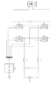
- FIG. 1 is a circuit diagram of an electric vehicle vehicle charger according to an embodiment of the present application.
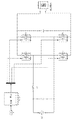
- FIG. 2 is a circuit diagram of an electric vehicle vehicle charger according to another embodiment of the present application.
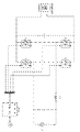
- FIG. 3 is a circuit diagram of an electric vehicle vehicle charger according to still another embodiment of the present application.
- FIG. 4 is a flowchart of a method for controlling an electric vehicle on-board charger according to an embodiment of the present application
- FIG. 5 is a schematic diagram of control waveforms of four switching tubes when the H-bridge is controlled to charge the power battery in the first mode according to an embodiment of the present application;
- FIG. 6 is a schematic diagram showing control waveforms of four switching tubes when the H-bridge is controlled to charge the power battery in the second mode according to an embodiment of the present application;
- FIG. 7 is a control flow chart when a power battery is charged by a vehicle charger according to an embodiment of the present application.
- FIG. 8 is a schematic diagram showing control waveforms of four switching tubes when the H-bridge is controlled in the first manner to discharge the power battery to the outside according to an embodiment of the present application;
- FIG. 9 is a schematic diagram showing control waveforms of four switching tubes when the H-bridge is controlled in a second manner to discharge the power battery to the outside according to an embodiment of the present application;
- an electric vehicle vehicle charger according to an embodiment of the present application includes an H bridge, and the H bridge includes a first switch tube T1, a second switch tube T2, a third switch tube T3, and a fourth switch tube T4. .
- the H bridge includes a first switch tube T1, a second switch tube T2, a third switch tube T3, and a fourth switch tube T4. .
- the electric vehicle vehicle charger includes a first inductor L1 and a second inductor L2, wherein the first end of the first inductor L1 is connected to one end of the load or the positive end of the AC grid AC, and the second inductor L2 is One end is connected to the other end of the load or the negative end of the AC grid AC, and the second end of the first inductor L1 and the second end of the second inductor L2 are respectively connected to the H bridge.
- the electric vehicle vehicle charger includes only one inductor such as the first inductor L1, wherein the first end of the first inductor L1 is connected to one end of the load or the positive end of the AC grid AC, and the second end of the first inductor L1.
- the electric vehicle vehicle charger includes only one inductor, such as the first inductor L1, wherein the first end of the first inductor L1 is connected to the other end of the load or the negative terminal of the AC grid AC, and the first inductor L1 is The two ends are connected to the H bridge.
- the AC power can be supplied by the AC power grid; when the power battery is discharged to the outside through the vehicle charger, it can be discharged into the AC grid by grid-connected discharge, or it can be off-grid.
- the inverter ie the inverter, supplies power to the load.
- control method of the electric vehicle vehicle charger of the embodiment of the present application includes:
- the control waveforms of the four switching tubes when the H-bridge is controlled in the first manner to charge the power battery are as shown in FIG. 5.
- the H-bridge is controlled in the first mode A, when the instantaneous voltage of the grid supplied to the on-board charger is greater than 0, the first switch tube T1 is controlled to be always on, and the second switch tube T2 is controlled to be always off, and the control The three switch tubes T3 and the fourth switch tube T4 are alternately turned on and off alternately, wherein when the third switch tube T3 and the fourth switch tube T4 are alternately turned on and off, the PWM waveform of the third switch tube T3 is controlled.
- the PWM waveform of the fourth switching transistor T4 is complementary, and the duty ratio of the PWM waveform for controlling the third switching transistor T3 is changed from large to small, and the duty ratio of the PWM waveform for controlling the fourth switching transistor T4 is changed from small to large. Small; when the instantaneous voltage of the grid supplied to the vehicle charger is less than 0, the third switch T3 is controlled to be always on, and the fourth switch T4 is controlled. In the always-off state, and controlling the first switch tube T1 and the second switch tube T2 to be alternately turned on and off, wherein when the first switch tube T1 and the second switch tube T2 are alternately turned on and off, the control is performed.
- the PWM waveform of the first switching transistor T1 and the PWM waveform of the second switching transistor T2 are complementary, and the duty ratio of the PWM waveform of the first switching transistor T1 is controlled to become larger and smaller, and the PWM waveform of the second switching transistor T2 is controlled.
- the duty cycle increases from small to small.
- the control waveforms of the four switching tubes when the H-bridge is controlled in the second mode to charge the power battery are as shown in FIG. 6.
- the H-bridge is controlled in the second mode B
- the second switch T2 is controlled to be in the always-on state
- the first switch T1 is controlled to be in the always-off state
- the control is performed.
- the three switch tubes T3 and the fourth switch tube T4 are alternately turned on and off alternately, wherein when the third switch tube T3 and the fourth switch tube T4 are alternately turned on and off, the PWM waveform of the third switch tube T3 is controlled.
- the PWM waveform of the fourth switching transistor T4 is complementary, and the duty ratio of the PWM waveform for controlling the third switching transistor T3 is changed from small to large, and the duty ratio of the PWM waveform for controlling the fourth switching transistor T4 is changed from large to small.
- the fourth switch tube T4 is controlled to be in the always-on state, and the third switch tube T3 is controlled to be in the always-off state, and the first switch tube T1 and the second switch are controlled.
- the tube T2 is alternately turned on and off, wherein when the first switch tube T1 and the second switch tube T2 are alternately turned on and off, the PWM waveform of the first switch tube T1 and the PWM waveform of the second switch tube T2 are controlled.
- Complementary and control first The duty ratio of the PWM waveform of the switching transistor T1 is changed from small to small, and the duty ratio of the PWM waveform that controls the second switching transistor T2 is changed from large to small.
- S2 specifically includes the following:
- S21 Select a mode for controlling the H bridge from the first mode A or the second mode B according to a relationship between the first charging total time TA and the second charging total time TB;
- S22 Control the H bridge according to the selected manner to perform temperature equalization control on the first switch tube, the second switch tube, the third switch tube, and the fourth switch tube.
- the first switch tube T1 remains open, and the second switch The tube T2 is kept turned off, and the third switch tube T3 and the fourth switch tube T4 are alternately turned on and off alternately, and the inductor in the vehicle charger is charged when the third switch tube T3 is turned on and the fourth switch tube T4 is turned off.
- the inductor When the third switch tube T3 is turned off and the fourth switch tube T4 is turned on, the inductor is discharged; when the instantaneous value of the grid voltage is less than 0, the third switch tube T3 is kept open, and the fourth switch tube T4 is kept turned off, the first switch tube T1 and the second switching tube T2 are alternately turned on and off alternately, and the inductor in the vehicle charger is charged when the first switching tube T1 is turned on and the second switching tube T2 is turned off, and the first switching tube T1 is turned off, and the second is turned off.
- the inductor discharges when the switch tube T2 is turned on. Since the inductor is charged when the first switch transistor T1 and the third switch transistor T3 are turned on, the turn-on duty ratio is large, so the first switch transistor T1 and the third switch transistor T3 may overheat.
- the first switch tube T1 remains off, and the second switch tube T2 is kept open, and the third switch tube T3 and the fourth switch tube T4 are alternately turned on and off alternately, and the inductor in the vehicle charger is charged when the fourth switch tube T4 is turned on and the third switch tube T3 is turned off.
- the inductor When the fourth switch tube T4 is turned off and the third switch tube T3 is turned on, the inductor is discharged; when the instantaneous value of the grid voltage is less than 0, the fourth switch tube T4 is kept open, and the third switch tube T3 is kept turned off, the first switch tube T1 and The second switch tube T2 is alternately turned on and off alternately, and the inductor in the vehicle charger is charged when the second switch tube T2 is turned on, and the first switch tube T1 is turned off, and the second switch tube T2 is turned off, and the first switch tube is turned off.
- the inductor discharges when T1 is turned on. Since the inductor is charged when the second switch tube T2 and the fourth switch tube T4 are turned on, the turn-on duty ratio is large, so the second switch tube T2 and the fourth switch tube T4 are overheated.
- the time for controlling the H-bridge by the first mode A is recorded, so that the One mode controls the first charging total time TA of the H bridge, and then stores;
- the second mode B controls the H bridge to enable the vehicle charger to charge the power battery, the second mode B is used to control the H bridge. Time, so that the second total charging time TB of the H-bridge is controlled in the second way, and then stored.
- the relationship between the first charging total time TA and the second charging total time TB is determined, and finally, the manner of controlling the H bridge is selected according to the relationship between the first charging total time TA and the second charging total time TB, thereby realizing Temperature equalization control is performed on the first switch tube, the second switch tube, the third switch tube, and the fourth switch tube.
- the manner of controlling the H bridge is selected according to the relationship between the total charging total time TA and the second total charging time TB, specifically, when the first charging total time TA is greater than the second charging total.
- the second mode is selected to control the H bridge; when the first total charging time TA is less than the second total charging time TB, the first mode is selected to control the H bridge; when the first charging total time TA is equal to the second
- the first mode or the second mode is selected to control the H bridge.
- the foregoing control method of the electric vehicle on-board charger includes:
- the first charging total time TA of controlling the H bridge in the first mode A and the second charging total time TB of the H bridge in the second mode B are read.
- S506. Determine whether the charging process ends. If yes, execute S507; if no, return to S505.
- S509 Select the first mode A to control the H bridge.
- the current charging time is recorded, so that the first charging total time TA is updated according to the first charging total time TA obtained from the storage area at the start of the current charging plus the current charging time.
- the first mode A is selected for the H-bridge control, the first charging total time TA is updated according to the first charging total time TA obtained from the storage area at the start of the current charging, and the current charging time is updated;
- the second mode B controls the H-bridge to update the second total charging time TB according to the second charging total time TB acquired from the storage area at the start of the charging plus the current charging time.
- the H-bridge is controlled in the first mode or the second mode each time charging, and recording the first charging total time TA when using the first mode and the second charging total time TB when using the second mode, Then, the relationship between the first charging total time TA and the second charging total time TB is judged, thereby selecting a method for controlling the H-bridge, and the switching tubes T1 and T2 in the H-bridge can be realized in the entire life cycle of the vehicle charger.
- the heat generation and overcurrent of T3 and T4 are relatively balanced, so that the working life of the vehicle charger can be increased and the failure rate can be reduced.
- the control waveform of the four switching tubes when the H-bridge is controlled in the first manner to discharge the power battery to the outside is as shown in FIG. 8.
- the H-bridge is controlled in the first mode A, when the external discharge instantaneous voltage of the on-vehicle charger is greater than 0, the first switch tube T1 is controlled to be always on, and the second switch tube T2 is controlled to be always off, and the control is performed.
- the three switch tubes T3 and the fourth switch tube T4 are alternately turned on and off alternately, wherein when the third switch tube T3 and the fourth switch tube T4 are alternately turned on and off, the PWM waveform of the third switch tube T3 is controlled.
- the PWM waveform of the fourth switching transistor T4 is complementary, and the duty ratio of the PWM waveform for controlling the third switching transistor T3 is changed from large to small, and the duty ratio of the PWM waveform for controlling the fourth switching transistor T4 is changed from small to large. Small; when the external discharge instantaneous voltage of the vehicle charger is less than 0, the third switch tube T3 is controlled to be always open, and the fourth switch tube is controlled.
- T4 is in the always-off state, and controls the first switch tube T1 and the second switch tube T2 to be alternately turned on and off alternately, wherein when the first switch tube T1 and the second switch tube T2 are alternately turned on and off, Controlling the PWM waveform of the first switching transistor T1 and the PWM waveform of the second switching transistor T2 are complementary, and controlling the duty ratio of the PWM waveform of the first switching transistor T1 to become larger and smaller, and controlling the PWM of the second switching transistor T2
- the duty cycle of the waveform changes from small to small.
- control waveform of the four switching tubes when the H-bridge is controlled in the second manner to discharge the power battery to the outside is as shown in FIG.
- the H-bridge is controlled in the second mode B, when the external discharge instantaneous voltage of the vehicle charger is greater than 0, the second switching transistor T2 is controlled to be in the always-on state, and the first switching transistor T1 is controlled to be in the always-off state, and the control is performed.
- the three switch tubes T3 and the fourth switch tube T4 are alternately turned on and off alternately, wherein when the third switch tube T3 and the fourth switch tube T4 are alternately turned on and off, the PWM waveform of the third switch tube T3 is controlled.
- the PWM waveform of the fourth switching transistor T4 is complementary, and the duty ratio of the PWM waveform for controlling the third switching transistor T3 is changed from small to large, and the duty ratio of the PWM waveform for controlling the fourth switching transistor T4 is changed from large to small.
- the fourth switch tube T4 is controlled to be in the always-on state, and the third switch tube T3 is controlled to be in the always-off state, and the first switch tube T1 and the second switch are controlled.
- the tube T2 is alternately turned on and off, wherein when the first switch tube T1 and the second switch tube T2 are alternately turned on and off, the PWM waveform of the first switch tube T1 and the PWM waveform of the second switch tube T2 are controlled.
- Complementary and control first The duty ratio of the PWM waveform of the switching transistor T1 is changed from small to small, and the duty ratio of the PWM waveform that controls the second switching transistor T2 is changed from large to small.
- the first switch tube T1 remains open, The second switch tube T2 is kept turned off, and the third switch tube T3 and the fourth switch tube T4 are alternately turned on and off alternately, and the inductor in the vehicle charger is turned on when the third switch tube T3 is turned off and the fourth switch tube T4 is turned on.
- the first switching tube T1 remains turned off, and the second The switch tube T2 is kept open, and the third switch tube T3 and the fourth switch tube T4 are alternately turned on and off alternately, and the inductor in the vehicle charger is charged when the fourth switch tube T4 is turned off and the third switch tube T3 is turned on.
- the fourth switch tube T4 is opened and opened third.
- the inductor discharges; when the instantaneous value of the external discharge voltage is less than 0, the fourth switch tube T4 is kept open, the third switch tube T3 is kept turned off, and the first switch tube T1 and the second switch tube T2 are alternately complementary. Turning on and off, and charging the inductor in the vehicle charger when the second switching transistor T2 is turned off and the first switching transistor T1 is turned on, and the inductor is discharged when the second switching transistor T2 is turned on and the first switching transistor T1 is turned off.
- the first switch tube T1 and the third switch tube T3 are charged when the first switch tube T1 and the third switch tube T3 are turned on, the first switch tube T1 and the third switch tube T3 are turned off with a current to perform a hard switch, so the first switch tube T1 and the third switch tube T3 will overheat.
- the H-bridge can be controlled by the first mode A to discharge the power battery through the vehicle charger until the time when the first bridge A is controlled by the first mode A reaches the first discharge set time Tm, and the switch is adopted.
- the second mode B can also be used to control the H bridge to discharge the power battery through the vehicle charger until the second mode B controls the H bridge.
- the second discharge setting time Tn is switched to control the H bridge by using the first mode A to discharge the power battery through the vehicle charger until the time when the H-bridge is controlled by the first mode A reaches the first discharge set time Tm, A discharge cycle is thus completed and repeated in accordance with such a discharge cycle until the discharge of the power battery is completed.
- the alternate control of the H-bridge according to the first discharge set time Tm and the second discharge set time Tn in the above S2 includes: when the time of controlling the H-bridge by the first mode reaches the first discharge set time Tm, The second mode controls the H bridge until the time for controlling the H bridge in the second mode reaches the second discharge set time Tn; or when the time for controlling the H bridge in the second mode reaches the second discharge set time Tn, the first The mode controls the H bridge until the time for controlling the H bridge in the first mode reaches the first discharge set time Tm.
- controlling the first discharge set time Tm of the H-bridge in the first manner may be equal to controlling the second discharge set time Tn of the H-bridge in the second manner.
- the foregoing control method of the electric vehicle on-board charger includes:
- the first mode A is used to control the H bridge to discharge the power battery through the vehicle charger.
- the second mode B is used to control the H bridge to discharge the power battery through the vehicle charger.
- control method of the electric vehicle vehicle charger of the embodiment of the present application can ensure that the first switch tube, the second switch tube, the third switch tube and the fourth switch tube are heated during the external discharge process of the power battery through the vehicle charger each time. Relative balance, improve the working life of the car charger.
- the first charging total time TA of controlling the H bridge in the first manner and the second charging total time of controlling the H bridge in the second manner are acquired.
- TB selecting a manner of controlling the H bridge according to a relationship between the first charging total time TA and the second charging total time TB, to the first switching tube, the second switching tube, the third switching tube, and the fourth switch
- the tube performs temperature equalization control; when the power battery is externally discharged, obtaining a first discharge set time Tm for controlling the H bridge in a first manner and a second discharge set time Tn for controlling the H bridge in a second manner, and according to the first discharge setting
- the time Tm and the second discharge set time Tn alternately control the H-bridge to perform temperature equalization control on the first switching transistor, the second switching transistor, the third switching transistor, and the fourth switching transistor. Therefore, the heat generation of each switch tube is relatively balanced, thereby improving the working life of the switch tube in the H
- an electric vehicle vehicle charger includes an H-bridge and a controller such as an MCU (Micro Control Unit).
- the H bridge includes a first switch tube T1, a second switch tube T2, a third switch tube T3, and a fourth switch tube T4.
- the controller is configured to acquire a first charging total time TA for controlling the H bridge in a first manner and a second charging total time TB for controlling the H bridge in a second manner when the vehicle charger charges the power battery of the electric vehicle, and according to The relationship between the first charging total time TA and the second charging total time TB selects a manner of controlling the H bridge to the first switching tube T1, the second switching tube T2, the third switching tube T3, and the fourth switching tube.
- T4 performs temperature equalization control, and is also used to obtain a first discharge set time Tm for controlling the H bridge in a first manner and a second control H bridge in a second manner when the power battery of the electric vehicle is externally discharged by the vehicle charger. Discharging the set time Tn, and alternately controlling the H bridge according to the first discharge set time Tm and the second discharge set time Tn to the first switch
- the tube T1, the second switch tube T2, the third switch tube T3, and the fourth switch tube T4 perform temperature equalization control, wherein the first discharge set time Tm and the second discharge set time Tn are pre-charged for each discharge cycle in the discharge process Set.
- the controller selects a mode for controlling the H bridge according to a relationship between the first charging total time TA and the second charging total time TB, wherein when the first charging total time TA is greater than the second When the total charging time is TB, the controller selects the second mode to control the H bridge; when the first charging total time TA is less than the second charging total time TB, the controller selects the first mode to control the H bridge; when the first charging When the total time TA is equal to the second total charging time TB, the controller selects the first mode or the second mode to control the H-bridge.
- the controller controls the H-bridge by using the first mode A to enable the vehicle charger to charge the power battery, and records the time when the H-bridge is controlled by the first mode A, thereby The first charging total time TA of the H bridge can be controlled in the first manner, and then stored; the controller uses the second mode B to control the H bridge to enable the vehicle charger to charge the power battery, and the second mode B is recorded. The time during which the H-bridge is controlled, so that the second total charging time TB of the H-bridge is controlled in the second manner, and then stored.
- the controller determines a relationship between the first charging total time TA and the second charging total time TB, and finally selects a mode for controlling the H bridge according to the relationship between the first charging total time TA and the second charging total time TB, Thereby, temperature equalization control is performed on the first switch tube, the second switch tube, the third switch tube and the fourth switch tube.
- the controller when the controller controls the H-bridge in the first manner, when the grid instantaneous voltage supplied to the on-vehicle charger is greater than 0, the controller controls the first switch tube T1 to be in the always-on state, and controls the first The second switch tube T2 is in the always off state, and the third switch tube T3 and the fourth switch tube T4 are alternately turned on and off, wherein the third switch tube T3 and the fourth switch tube T4 are alternately turned on and off.
- the PWM waveform of the third switching transistor T3 is controlled to be complementary to the PWM waveform of the fourth switching transistor T4, and the duty ratio of the PWM waveform of the third switching transistor T3 is controlled to be larger and smaller, and the fourth switching transistor is controlled.
- the duty ratio of the PWM waveform of T4 is changed from small to small and smaller; when the instantaneous voltage of the grid supplied to the vehicle charger is less than 0, the controller controls the third switching transistor T3 to be in the always-on state, and controls the fourth switching tube T4 to be in the same state.
- the controller controls the H-bridge in the second mode
- the controller controls the second switch tube T2 to be in the always-on state, and controls the first switch tube T1 to be in the same state. Turning off the state, and controlling the third switch tube T3 and the fourth switch tube T4 to alternately turn on and off, wherein the third switch is controlled when the third switch tube T3 and the fourth switch tube T4 are alternately turned on and off.
- the PWM waveform of the switching transistor T3 is complementary to the PWM waveform of the fourth switching transistor T4, and the duty ratio of the PWM waveform controlling the third switching transistor T3 is changed from small to large.
- the duty ratio of the PWM waveform for controlling the fourth switching transistor T4 is changed from large to small and larger; when the instantaneous voltage of the grid supplied to the vehicle charger is less than 0, the controller controls the fourth switching transistor T4 to be always turned on. And controlling the third switch tube T3 to be in the always off state, and controlling the first switch tube T1 and the second switch tube T2 to alternately turn on and off alternately, wherein the first switch tube T1 and the second switch tube T2 are alternately controlled.
- the PWM waveform of the first switching transistor T1 and the PWM waveform of the second switching transistor T2 are complementary, and the duty ratio of the PWM waveform of the first switching transistor T1 is controlled to be smaller and smaller, and the control is controlled.
- the duty ratio of the PWM waveform of the second switching transistor T2 is changed from large to small.
- the controller alternately controls the H bridge according to the first discharge set time Tm and the second discharge set time Tn, wherein the time when the H bridge is controlled by the first mode reaches the first discharge set time
- Tm the H-bridge is controlled in the second mode until the time when the H-bridge is controlled in the second mode reaches the second discharge set time Tn; or when the time in which the H-bridge is controlled in the second mode reaches the second discharge set-time Tn
- the H-bridge is controlled in the first manner until the time when the H-bridge is controlled in the first manner reaches the first discharge set time Tm.
- the controller first sets the first discharge set time Tm and the second discharge set time Tn, and then passes the on-board charger in the power battery.
- the first mode A can be used to control the H bridge to discharge the power battery through the vehicle charger until the time when the first mode A is used to control the H bridge reaches the first discharge set time Tm.
- the second mode B can also be used to control the H bridge to discharge the power battery through the vehicle charger until the second mode B controls the H bridge.
- the second discharge setting time Tn is switched to control the H bridge by using the first mode A to discharge the power battery through the vehicle charger until the time when the H-bridge is controlled by the first mode A reaches the first discharge set time Tm, A discharge cycle is thus completed and repeated in accordance with such a discharge cycle until the discharge of the power battery is completed.
- the first discharge set time Tm of controlling the H bridge in the first manner may be equal to the second discharge set time Tn of controlling the H bridge in the second manner.
- the controller when the controller controls the H-bridge in the first manner, when the external discharge instantaneous voltage of the on-board charger is greater than 0, the controller controls the first switch T1 to be always on, and controls the first Two switch
- the tube T2 is in the always-off state, and the third switching tube T3 and the fourth switching tube T4 are alternately turned on and off, wherein when the third switching tube T3 and the fourth switching tube T4 are alternately turned on and off.
- the PWM waveform of the third switching transistor T3 is controlled to be complementary to the PWM waveform of the fourth switching transistor T4, and the duty ratio of the PWM waveform of the third switching transistor T3 is controlled to be larger and smaller, and the fourth switching transistor T4 is controlled.
- the duty ratio of the PWM waveform changes from small to small and becomes smaller; when the external discharge instantaneous voltage of the vehicle charger is less than 0, the controller controls the third switching tube T3 to be in the always-on state, and controls the fourth switching tube T4 to be always turned off. a state, and controlling the first switch tube T1 and the second switch tube T2 to alternately turn on and off, wherein the first switch tube is controlled when the first switch tube T1 and the second switch tube T2 are alternately turned on and off.
- the PWM waveform of T1 and the PWM waveform of the second switching transistor T2 are complementary, and the duty ratio of the PWM waveform of the first switching transistor T1 is controlled to be larger and smaller, and the duty ratio of the PWM waveform of the second switching transistor T2 is controlled. From small to large, then smaller.
- the controller controls the H-bridge in the second mode, when the external discharge instantaneous voltage of the vehicle charger is greater than 0, the controller controls the second switch tube T2 to be in the always-on state, and controls the first switch tube T1 to be always turned off. a state, and controlling the third switch tube T3 and the fourth switch tube T4 to be alternately turned on and off, wherein the third switch tube is controlled when the third switch tube T3 and the fourth switch tube T4 are alternately turned on and off.
- the PWM waveform of T3 is complementary to the PWM waveform of the fourth switching transistor T4, and the duty ratio of the PWM waveform that controls the third switching transistor T3 is changed from small to large, and the duty ratio of the PWM waveform of the fourth switching transistor T4 is controlled from
- the controller controls the fourth switching tube T4 to be in the always-on state, and controls the third switching tube T3 to be in the always-off state, and controls the first
- the switch tube T1 and the second switch tube T2 are alternately turned on and off alternately, wherein the PWM waveform and the first switch tube T1 are controlled when the first switch tube T1 and the second switch tube T2 are alternately turned on and off.
- Two switch tube T2 Complementary PWM waveforms, and controls the duty cycle of the PWM waveform of the first switching transistor T1 becomes small large small then, controls the second switching transistor T2 is then the duty ratio of the PWM waveform increases from large to small.
- the first switch tube T1, the second switch tube T2, the third switch tube T3, and the fourth switch tube T4 are all IGBTs (Insulated Gate Bipolar). Transistor, insulated gate bipolar transistor), of course, in other embodiments of the present application, the first switch transistor T1, the second switch transistor T2, the third switch transistor T3, and the fourth switch transistor T4 may also be MOS transistors.
- the controller when the power battery is charged, acquires the first charging total time TA of controlling the H bridge in the first manner and the second charging total time TB of controlling the H bridge in the second manner. And selecting a manner of controlling the H bridge according to a relationship between the first charging total time TA and the second charging total time TB, to the first switching tube, the second switching tube, the third switching tube, and the fourth switching tube Performing temperature equalization control, and when the power battery is externally discharged, the controller acquires a first discharge set time Tm that controls the H bridge in a first manner and a second discharge set time Tn that controls the H bridge in a second manner, and according to the first The discharge setting time Tm and the second discharge setting time Tn alternately control the H-bridge to perform temperature equalization control on the first switching transistor, the second switching transistor, the third switching transistor, and the fourth switching transistor.
- the system makes the heat generation of each switch tube relatively balanced, and improves the working life of the switch tube in the H-bridge,
- an embodiment of the present application also proposes an electric vehicle including the above-described electric vehicle on-board charger.
- the first switch tube, the second switch tube, the third switch tube, and the fourth switch tube in the H-bridge can be realized.
- the temperature equalization control makes the heat generation of each switch tube relatively balanced, and improves the working life of the switch tube in the H bridge, thereby extending the life cycle of the vehicle charger.
- first and second are used for descriptive purposes only and are not to be construed as indicating or implying a relative importance or implicitly indicating the number of technical features indicated.
- features defining “first” or “second” may include at least one of the features, either explicitly or implicitly.
- the meaning of "a plurality” is at least two, such as two, three, etc., unless specifically defined otherwise.
- the terms “installation”, “connected”, “connected”, “fixed” and the like shall be understood broadly, and may be either a fixed connection or a detachable connection, unless otherwise explicitly stated and defined. , or integrated; can be mechanical or electrical connection; can be directly connected, or indirectly connected through an intermediate medium, can be the internal communication of two elements or the interaction of two elements, unless otherwise specified Limited.
- the specific meanings of the above terms in the present application can be understood on a case-by-case basis.
- the first feature "on” or “below” the second feature may be the direct contact of the first and second features, or the first and second features are indirectly through the intermediate medium, unless otherwise explicitly stated and defined. contact.
- the first feature "above”, “above” and “above” the second feature may be that the first feature is directly above or above the second feature, or merely that the first feature level is higher than the second feature.
- the first feature “below”, “below” and “below” the second feature may be that the first feature is directly below or obliquely below the second feature, or merely that the first feature level is less than the second feature.
Landscapes
- Engineering & Computer Science (AREA)
- Power Engineering (AREA)
- Transportation (AREA)
- Mechanical Engineering (AREA)
- Life Sciences & Earth Sciences (AREA)
- Sustainable Development (AREA)
- Sustainable Energy (AREA)
- Charge And Discharge Circuits For Batteries Or The Like (AREA)
Abstract
一种电动汽车车载充电器的控制方法。控制方法包括:当动力电池充电时,获取以第一方式控制H桥的第一充电总时间TA和以第二方式控制H桥的第二充电总时间TB;根据TA与TB之间的关系选择对H桥进行控制的方式,以对第一至第四开关管进行控制;当动力电池对外放电时,获取以第一方式控制H桥的第一放电设置时间Tm和以第二方式控制H桥的第二放电设置时间Tn;根据Tm和Tn对H桥进行交替控制以对第一至第四开关管进行温度均衡控制。还公开了一种电动汽车及其车载充电器。
Description
相关申请的交叉引用
本申请基于申请号为201510955965.0、申请日为2015/12/18的中国专利申请提出,并要求该中国专利申请的优先权,该中国专利申请的全部内容在此引入本申请作为参考。
本申请涉及电动汽车技术领域,特别涉及一种电动汽车车载充电器的控制方法、一种电动汽车车载充电器以及一种电动汽车。
伴随着电动汽车商业化进度,电动汽车车载充电器已成为电动汽车重要零部件之一。
其中,通过控制车载充电器对整车进行充电和使整车对外放电的方法有很多,而相关技术中大多采用单相H桥的控制方法,而采用单相H桥的控制方法一般包括双极性控制方法和单极性控制方法。
但是,采用双极性控制方法时,H桥中的4个开关管都处于高频开关状态,开关损耗较高,产生的热损耗较大;采用单极性控制方法时,尽管可以一定程度上解决采用双极性控制方法时的开关管热损耗,但是整车充电或放电过程中总是按照固定方式来控制H桥中的四个开关管,H桥中部分开关管需要带电流关断,带电流关断的开关管的过热问题并不能得到有效解决。
因此,不管采用双极性控制方法还是单极性控制方法,均不能有效解决H桥中的开关管的发热问题,影响开关管的工作寿命。
发明内容
本申请旨在至少在一定程度上解决上述技术中的技术问题之一。为此,本申请的第一个目的在于提出一种电动汽车车载充电器的控制方法,能够使得H桥中的第一至第四开关管的发热相对平衡,提高H桥中开关管的工作寿命。
本申请的第二个目的在于提出一种电动汽车车载充电器。本申请的第三个目的在于提出一种电动汽车。
为达到上述目的,本申请一方面实施例提出了一种电动汽车车载充电器的控制方法,所述车载充电器包括H桥,所述H桥包括第一开关管、第二开关管、第三开关管和第四开
关管,所述控制方法包括:当所述车载充电器对所述电动汽车的动力电池进行充电时,获取以第一方式控制所述H桥的第一充电总时间TA和以第二方式控制所述H桥的第二充电总时间TB;根据所述第一充电总时间TA与所述第二充电总时间TB之间的关系选择对所述H桥进行控制的方式,以对所述第一开关管、第二开关管、第三开关管和第四开关管进行温度均衡控制;当所述电动汽车的动力电池通过所述车载充电器对外进行放电时,获取以第一方式控制所述H桥的第一放电设置时间Tm和以第二方式控制所述H桥的第二放电设置时间Tn;根据所述第一放电设置时间Tm和所述第二放电设置时间Tn对所述H桥进行交替控制以对所述第一开关管、第二开关管、第三开关管和第四开关管进行温度均衡控制,其中所述第一放电设置时间Tm和所述第二放电设置时间Tn是为放电过程中的每个放电循环预设的。
根据本申请实施例的电动汽车车载充电器的控制方法,当动力电池充电时,获取以第一方式控制H桥的第一充电总时间TA和以第二方式控制H桥的第二充电总时间TB,并根据第一充电总时间TA与第二充电总时间TB之间的关系选择对H桥进行控制的方式,以对第一开关管、第二开关管、第三开关管和第四开关管进行温度均衡控制;当动力电池对外放电时,获取以第一方式控制H桥的第一放电设置时间Tm和以第二方式控制H桥的第二放电设置时间Tn,并根据第一放电设置时间Tm和第二放电设置时间Tn对H桥进行交替控制以对第一开关管、第二开关管、第三开关管和第四开关管进行温度均衡控制。从而使得每个开关管的发热相对平衡,提高H桥中开关管的工作寿命,进而延长车载充电器的生命周期。
为达到上述目的,本申请另一方面实施例提出的一种电动汽车车载充电器,包括:H桥,所述H桥包括第一开关管、第二开关管、第三开关管和第四开关管;控制器,所述控制器用于在所述车载充电器对所述电动汽车的动力电池进行充电时获取以第一方式控制所述H桥的第一充电总时间TA和以第二方式控制所述H桥的第二充电总时间TB,并根据所述第一充电总时间TA与所述第二充电总时间TB之间的关系选择对所述H桥进行控制的方式,以对所述第一开关管、第二开关管、第三开关管和第四开关管进行温度均衡控制,并且还用于在所述电动汽车的动力电池通过所述车载充电器对外进行放电时获取以第一方式控制所述H桥的第一放电设置时间Tm和以第二方式控制所述H桥的第二放电设置时间Tn,并根据所述第一放电设置时间Tm和所述第二放电设置时间Tn对所述H桥进行交替控制以对所述第一开关管、第二开关管、第三开关管和第四开关管进行温度均衡控制,其中所述第一放电设置时间Tm和所述第二放电设置时间Tn是为放电过程中的每个放电循环预设的。
根据本申请实施例的电动汽车车载充电器,当动力电池充电时,控制器获取以第一方式控制H桥的第一充电总时间TA和以第二方式控制H桥的第二充电总时间TB,并根据第一充电总时间TA与第二充电总时间TB之间的关系选择对H桥进行控制的方式,以对第一开关管、第二开关管、第三开关管和第四开关管进行温度均衡控制,并且当动力电池对外放电时,控制器获取以第一方式控制H桥的第一放电设置时间Tm和以第二方式控制H桥的第二放电设置时间Tn,并根据第一放电设置时间Tm和第二放电设置时间Tn对H桥进行交替控制以对第一开关管、第二开关管、第三开关管和第四开关管进行温度均衡控制,使得每个开关管的发热相对平衡,提高H桥中开关管的工作寿命,从而延长车载充电器的生命周期。
此外,本申请的实施例还提出了一种电动汽车,其包括上述的电动汽车车载充电器。
本申请实施例的电动汽车,在动力电池通过上述的车载充电器进行充电和放电时,能够实现对H桥中的第一开关管、第二开关管、第三开关管和第四开关管进行温度均衡控制,使得每个开关管的发热相对平衡,提高H桥中开关管的工作寿命,从而延长了车载充电器的生命周期。
图1为根据本申请一个实施例的电动汽车车载充电器的电路示意图;
图2为根据本申请另一个实施例的电动汽车车载充电器的电路示意图;
图3为根据本申请又一个实施例的电动汽车车载充电器的电路示意图;
图4为根据本申请实施例的电动汽车车载充电器的控制方法的流程图;
图5为根据本申请一个实施例的采用第一方式对H桥进行控制以对动力电池充电时的四个开关管的控制波形示意图;
图6为根据本申请一个实施例的采用第二方式对H桥进行控制以对动力电池充电时的四个开关管的控制波形示意图;
图7为根据本申请一个具体实施例的通过车载充电器给动力电池充电时的控制流程图;
图8为根据本申请一个实施例的采用第一方式对H桥进行控制以使动力电池对外放电时的四个开关管的控制波形示意图;
图9为根据本申请一个实施例的采用第二方式对H桥进行控制以使动力电池对外放电时的四个开关管的控制波形示意图;以及
图10为根据本申请一个具体实施例的动力电池通过车载充电器对外放电时的控制流
程图。
下面详细描述本申请的实施例,所述实施例的示例在附图中示出,其中自始至终相同或类似的标号表示相同或类似的元件或具有相同或类似功能的元件。下面通过参考附图描述的实施例是示例性的,旨在用于解释本申请,而不能理解为对本申请的限制。
下面参照附图来描述本申请实施例提出的电动汽车车载充电器的控制方法、电动汽车车载充电器以及具有该车载充电器的电动汽车。
图1至图3示出了根据本申请实施例的电动汽车车载充电器的连接方式。如图1至图3所示,根据本申请实施例的电动汽车车载充电器包括H桥,H桥包括第一开关管T1、第二开关管T2、第三开关管T3和第四开关管T4。如图1所示,电动汽车车载充电器包括第一电感L1和第二电感L2,其中第一电感L1的第一端与负载的一端或交流电网AC的正极端相连,第二电感L2的第一端与负载的另一端或交流电网AC的负极端相连,第一电感L1的第二端和第二电感L2的第二端分别和H桥相连。如图2所示,电动汽车车载充电器仅包括一个电感例如第一电感L1,其中第一电感L1的第一端与负载的一端或交流电网AC的正极端相连,第一电感L1的第二端和H桥相连。如图3所示,电动汽车车载充电器仅包括一个电感例如第一电感L1,其中第一电感L1的第一端与负载的另一端或交流电网AC的负极端相连,第一电感L1的第二端和H桥相连。当车载充电器对电动汽车的动力电池进行充电时,可由交流电网AC提供电能;当动力电池通过车载充电器对外进行放电时,可以是并网放电即放电到交流电网AC,也可以是离网逆变即逆变给负载供电。
图4为根据本申请实施例的电动汽车车载充电器的控制方法的流程图。如图4所示,本申请实施例的电动汽车车载充电器的控制方法包括:
S1,当车载充电器对电动汽车的动力电池进行充电时,获取以第一方式控制H桥的第一充电总时间TA和以第二方式控制H桥的第二充电总时间TB。
根据本申请的一个实施例,采用第一方式对H桥进行控制以对动力电池充电时的四个开关管的控制波形如图5所示。以第一方式A控制H桥时,当供给车载充电器的电网瞬时电压大于0时,控制第一开关管T1处于一直开通状态,并控制第二开关管T2处于一直关断状态,以及控制第三开关管T3和第四开关管T4交替互补开通和关断,其中,在控制第三开关管T3和第四开关管T4交替互补开通和关断时,控制第三开关管T3的PWM波形和第四开关管T4的PWM波形互补,且控制第三开关管T3的PWM波形的占空比从大变小再变大,控制第四开关管T4的PWM波形的占空比从小变大再变小;当供给车载充电器的电网瞬时电压小于0时,控制第三开关T3处于一直开通状态,并控制第四开关管T4处
于一直关断状态,以及控制第一开关管T1和第二开关管T2交替互补开通和关断,其中,在控制第一开关管T1和第二开关管T2交替互补开通和关断时,控制第一开关管T1的PWM波形和第二开关管T2的PWM波形互补,且控制第一开关管T1的PWM波形的占空比从大变小再变大,控制第二开关管T2的PWM波形的占空比从小变大再变小。
根据本申请的一个实施例,采用第二方式对H桥进行控制以对动力电池充电时的四个开关管的控制波形如图6所示。以第二方式B控制H桥时,当供给车载充电器的电网瞬时电压大于0时,控制第二开关管T2处于一直开通状态,并控制第一开关管T1处于一直关断状态,以及控制第三开关管T3和第四开关管T4交替互补开通和关断,其中,在控制第三开关管T3和第四开关管T4交替互补开通和关断时,控制第三开关管T3的PWM波形和第四开关管T4的PWM波形互补,且控制第三开关管T3的PWM波形的占空比从小变大再变小,控制第四开关管T4的PWM波形的占空比从大变小再变大;当供给车载充电器的电网瞬时电压小于0时,控制第四开关管T4处于一直开通状态,并控制第三开关管T3处于一直关断状态,以及控制第一开关管T1和第二开关管T2交替互补开通和关断,其中,在控制第一开关管T1和第二开关管T2交替互补开通和关断时,控制第一开关管T1的PWM波形和第二开关管T2的PWM波形互补,且控制第一开关管T1的PWM波形的占空比从小变大再变小,控制第二开关管T2的PWM波形的占空比从大变小再变大。
S2,根据第一充电总时间TA与第二充电总时间TB之间的关系选择对H桥进行控制的方式,以对第一开关管、第二开关管、第三开关管和第四开关管进行温度均衡控制。
在具体实施中,S2具体包括以下:
S21,根据第一充电总时间TA与第二充电总时间TB之间的关系从第一方式A或第二方式B中选择对H桥进行控制的方式;
S22,根据选择的方式对H桥进行控制,以对第一开关管、第二开关管、第三开关管和第四开关管进行温度均衡控制。
需要说明的是,在车载充电器对动力电池充电的过程中,如果仅采用第一方式A对H桥进行控制,电网电压瞬时值大于0时,第一开关管T1保持一直开通,第二开关管T2保持一直关断,第三开关管T3和第四开关管T4交替互补开通和关断,而在第三开关管T3开通、第四开关管T4关断时车载充电器中的电感充电,在第三开关管T3关断、第四开关管T4开通时电感放电;电网电压瞬时值小于0时,第三开关管T3保持一直开通,第四开关管T4保持一直关断,第一开关管T1和第二开关管T2交替互补开通和关断,而在第一开关管T1开通、第二开关管T2关断时车载充电器中的电感充电,在第一开关管T1关断、第二开关管T2开通时电感放电。由于第一开关管T1和第三开关管T3开通时给电感充电,开通占空比较大,因此第一开关管T1、第三开关管T3会过热。
同样地,在车载充电器对动力电池充电的过程中,如果仅采用第二方式B对H桥进行控制,电网电压瞬时值大于0时,第一开关管T1保持一直关断,第二开关管T2保持一直开通,第三开关管T3和第四开关管T4交替互补开通和关断,而在第四开关管T4开通、第三开关管T3关断时车载充电器中的电感充电,在第四开关管T4关断、第三开关管T3开通时电感放电;电网电压瞬时值小于0时,第四开关管T4保持一直开通,第三开关管T3保持一直关断,第一开关管T1和第二开关管T2交替互补开通和关断,而在第二开关管T2开通、第一开关管T1关断时车载充电器中的电感充电,在第二开关管T2关断、第一开关管T1开通时电感放电。由于第二开关管T2和第四开关管T4开通时给电感充电,开通占空比较大,因此第二开关管T2、第四开关管T4会过热。
因此,在本申请的实施例中,采用第一方式A对H桥进行控制以使车载充电器对动力电池充电时,记录采用第一方式A对H桥进行控制的时间,从而可得到以第一方式控制H桥的第一充电总时间TA,然后进行存储;采用第二方式B对H桥进行控制以使车载充电器对动力电池充电时,记录采用第二方式B对H桥进行控制的时间,从而可得到以第二方式控制H桥的第二充电总时间TB,然后进行存储。然后判断第一充电总时间TA与第二充电总时间TB之间的关系,最后根据第一充电总时间TA与第二充电总时间TB之间的关系选择对H桥进行控制的方式,从而实现对第一开关管、第二开关管、第三开关管和第四开关管进行温度均衡控制。
根据本申请的一个实施例,根据第一充电总时间TA与第二充电总时间TB之间的关系选择对H桥进行控制的方式,具体包括:当第一充电总时间TA大于第二充电总时间TB时,选择第二方式对H桥进行控制;当第一充电总时间TA小于第二充电总时间TB时,选择第一方式对H桥进行控制;当第一充电总时间TA等于第二充电总时间TB时,选择第一方式或第二方式对H桥进行控制。
具体而言,根据本申请的一个实施例,如图7所示,上述的电动汽车车载充电器的控制方法包括:
S501,充电开波,即在车载充电器对动力电池充电时,需要输出控制波形来对H桥中的开关管进行控制。
S502,读取以第一方式A控制H桥的第一充电总时间TA和以第二方式B控制H桥的第二充电总时间TB。
S503,判断第一充电总时间TA是否大于第二充电总时间TB。如果是,执行S504;如果否,执行S508。
S504,选择第二方式B对H桥进行控制。
S505,车载充电器对动力电池进行充电过程。
S506,判断本次充电过程是否结束。如果是,执行S507;如果否,返回S505。
S507,记录本次充电时间,从而根据本次充电开始时从存储区域获取的第二充电总时间TB加上本次充电时间来更新第二充电总时间TB。
S508,判断第一充电总时间TA是否小于第二充电总时间TB。如果是,执行S509;如果否,执行S513。
S509,选择第一方式A对H桥进行控制。
S510,车载充电器对动力电池进行充电过程。
S511,判断本次充电过程是否结束。如果是,执行S512;如果否,返回S510。
S512,记录本次充电时间,从而根据本次充电开始时从存储区域获取的第一充电总时间TA加上本次充电时间来更新第一充电总时间TA。
S513,选择第一方式A或者第二方式B对H桥进行控制。
S514,车载充电器对动力电池进行充电过程。
S515,判断本次充电过程是否结束。如果是,执行S516;如果否,返回S514。
S516,记录本次充电时间。其中,如果是选择第一方式A对H桥控制,从而根据本次充电开始时从存储区域获取的第一充电总时间TA加上本次充电时间来更新第一充电总时间TA;如果是选择第二方式B对H桥控制,从而根据本次充电开始时从存储区域获取的第二充电总时间TB加上本次充电时间来更新第二充电总时间TB。
因此,通过记录每次充电时是采用第一方式还是第二方式对H桥控制,并记录采用第一方式时的第一充电总时间TA和采用第二方式时的第二充电总时间TB,然后对第一充电总时间TA和第二充电总时间TB之间的关系进行判断,从而选择控制H桥的方式,能够在车载充电器的整个生命周期内实现H桥中的开关管T1、T2、T3和T4的发热量和过电流相对平衡,这样才可以增加车载充电器的工作寿命,减少故障率。
S3,当电动汽车的动力电池通过车载充电器对外进行放电时,获取以第一方式控制H桥的第一放电设置时间Tm和以第二方式控制H桥的第二放电设置时间Tn。
根据本申请的一个实施例,采用第一方式对H桥进行控制以使动力电池对外放电时的四个开关管的控制波形如图8所示。以第一方式A控制H桥时,当车载充电器的对外放电瞬时电压大于0时,控制第一开关管T1处于一直开通状态,并控制第二开关管T2处于一直关断状态,以及控制第三开关管T3和第四开关管T4交替互补开通和关断,其中,在控制第三开关管T3和第四开关管T4交替互补开通和关断时,控制第三开关管T3的PWM波形和第四开关管T4的PWM波形互补,且控制第三开关管T3的PWM波形的占空比从大变小再变大,控制第四开关管T4的PWM波形的占空比从小变大再变小;当车载充电器的对外放电瞬时电压小于0时,控制第三开关管T3处于一直开通状态,并控制第四开关管
T4处于一直关断状态,以及控制第一开关管T1和第二开关管T2交替互补开通和关断,其中,在控制第一开关管T1和第二开关管T2交替互补开通和关断时,控制第一开关管T1的PWM波形和第二开关管T2的PWM波形互补,且控制第一开关管T1的PWM波形的占空比从大变小再变大,控制第二开关管T2的PWM波形的占空比从小变大再变小。
并且,采用第二方式对H桥进行控制以使动力电池对外放电时的四个开关管的控制波形如图9所示。以第二方式B控制H桥时,当车载充电器的对外放电瞬时电压大于0时,控制第二开关管T2处于一直开通状态,并控制第一开关管T1处于一直关断状态,以及控制第三开关管T3和第四开关管T4交替互补开通和关断,其中,在控制第三开关管T3和第四开关管T4交替互补开通和关断时,控制第三开关管T3的PWM波形和第四开关管T4的PWM波形互补,且控制第三开关管T3的PWM波形的占空比从小变大再变小,控制第四开关管T4的PWM波形的占空比从大变小再变大;当车载充电器的对外放电瞬时电压小于0时,控制第四开关管T4处于一直开通状态,并控制第三开关管T3处于一直关断状态,以及控制第一开关管T1和第二开关管T2交替互补开通和关断,其中,在控制第一开关管T1和第二开关管T2交替互补开通和关断时,控制第一开关管T1的PWM波形和第二开关管T2的PWM波形互补,且控制第一开关管T1的PWM波形的占空比从小变大再变小,控制第二开关管T2的PWM波形的占空比从大变小再变大。
S4,根据第一放电设置时间Tm和第二放电设置时间Tn对H桥进行交替控制以对第一开关管、第二开关管、第三开关管和第四开关管进行温度均衡控制。
需要说明的是,在动力电池通过车载充电器对外放电的过程中,如果仅采用第一方式A对H桥进行控制,对外放电电压瞬时值大于0时,第一开关管T1保持一直开通,第二开关管T2保持一直关断,第三开关管T3和第四开关管T4交替互补开通和关断,而在第三开关管T3关断、第四开关管T4开通时车载充电器中的电感充电,在第三开关管T3开通、第四开关管T4关断时电感放电;对外放电电压瞬时值小于0时,第三开关管T3保持一直开通,第四开关管T4保持一直关断,第一开关管T1和第二开关管T2交替互补开通和关断,而在第一开关管T1关断、第二开关管T2开通时车载充电器中的电感充电,在第一开关管T1开通、第二开关管T2关断时电感放电。由于第二开关管T2和第四开关管T4开通时给电感充电,所以第二开关管T2和第四开关管T4带电流关断,进行硬开关,因此第二开关管T2和第四开关管T4会出现过热现象。
同样地,在动力电池通过车载充电器对外放电的过程中,如果仅采用第二方式B对H桥进行控制,对外放电电压瞬时值大于0时,第一开关管T1保持一直关断,第二开关管T2保持一直开通,第三开关管T3和第四开关管T4交替互补开通和关断,而在第四开关管T4关断、第三开关管T3开通时车载充电器中的电感充电,在第四开关管T4开通、第三开
关管T3关断时电感放电;对外放电电压瞬时值小于0时,第四开关管T4保持一直开通,第三开关管T3保持一直关断,第一开关管T1和第二开关管T2交替互补开通和关断,而在第二开关管T2关断、第一开关管T1开通时车载充电器中的电感充电,在第二开关管T2开通、第一开关管T1关断时电感放电。由于第一开关管T1和第三开关管T3开通时给电感充电,所以第一开关管T1和第三开关管T3带电流关断,进行硬开关,因此第一开关管T1和第三开关管T3会出现过热现象。
因此,在本申请的实施例中,动力电池每次通过车载充电器对外放电时,先设置第一放电设置时间Tm和第二放电设置时间Tn,然后在动力电池通过车载充电器对外放电的过程中,可先采用第一方式A对H桥进行控制以使动力电池通过车载充电器对外放电,直至采用第一方式A对H桥进行控制的时间达到第一放电设置时间Tm,切换到采用第二方式B对H桥进行控制以使动力电池通过车载充电器对外放电,直至采用第二方式B对H桥进行控制的时间达到第二放电设置时间Tn,如此完成一个放电循环(即一个放电循环时间=Tm+Tn),再切换到采用第一方式A对H桥进行控制以使动力电池通过车载充电器对外放电,直至采用第一方式A对H桥进行控制的时间达到第一放电设置时间Tm,然后切换到采用第二方式B对H桥进行控制以使动力电池通过车载充电器对外放电,直至采用第二方式B对H桥进行控制的时间达到第二放电设置时间Tn,……,如此反复进行,实现对H桥进行交替控制,从而实现对第一开关管、第二开关管、第三开关管和第四开关管进行温度均衡控制。当然,在动力电池对外放电的过程中,也可先采用第二方式B对H桥进行控制以使动力电池通过车载充电器对外放电,直至采用第二方式B对H桥进行控制的时间达到第二放电设置时间Tn,切换到采用第一方式A对H桥进行控制以使动力电池通过车载充电器对外放电,直至采用第一方式A对H桥进行控制的时间达到第一放电设置时间Tm,如此完成一个放电循环,并按照这样的放电循环反复进行,直至动力电池放电结束。
即言,上述S2中的根据第一放电设置时间Tm和第二放电设置时间Tn对H桥进行交替控制,包括:当采用第一方式控制H桥的时间达到第一放电设置时间Tm时,采用第二方式对H桥进行控制,直至采用第二方式控制H桥的时间达到第二放电设置时间Tn;或者当采用第二方式控制H桥的时间达到第二放电设置时间Tn时,采用第一方式对H桥进行控制,直至采用第一方式控制H桥的时间达到第一放电设置时间Tm。
根据本申请的一个实施例,以第一方式控制H桥的第一放电设置时间Tm可等于以第二方式控制H桥的第二放电设置时间Tn。
具体而言,根据本申请的一个实施例,如图10所示,上述的电动汽车车载充电器的控制方法包括:
S801,放电开波,即在动力电池通过车载充电器对外放电时,需要输出控制波形来对
H桥中的开关管进行控制。
S802,设置第一放电设置时间Tm和第二放电设置时间Tn。
S803,采用第一方式A对H桥进行控制以使动力电池通过车载充电器对外放电。
S804,判断采用第一方式A控制H桥的时间是否达到第一放电设置时间Tm。如果是,执行S805;如果否,返回S803。
S805,在放电过程中判断本次放电是否结束,如果是,执行S809,如果否,执行S806。
S806,采用第二方式B对H桥进行控制以使动力电池通过车载充电器对外放电。
S807,判断采用第二方式B控制H桥的时间是否达到第二放电设置时间Tn。如果是,执行S808;如果否,返回S806。
S808,在放电过程中判断本次放电是否结束,如果是,执行S809,如果否,执行S803。
S809,放电流程结束。
因此,本申请实施例的电动汽车车载充电器的控制方法可以使动力电池每次通过车载充电器对外放电过程中保证第一开关管、第二开关管、第三开关管和第四开关管发热相对平衡,提高车载充电器的工作寿命。
根据本申请实施例的电动汽车车载充电器的控制方法,当动力电池充电时,获取以第一方式控制H桥的第一充电总时间TA和以第二方式控制H桥的第二充电总时间TB,并根据第一充电总时间TA与第二充电总时间TB之间的关系选择对H桥进行控制的方式,以对第一开关管、第二开关管、第三开关管和第四开关管进行温度均衡控制;当动力电池对外放电时,获取以第一方式控制H桥的第一放电设置时间Tm和以第二方式控制H桥的第二放电设置时间Tn,并根据第一放电设置时间Tm和第二放电设置时间Tn对H桥进行交替控制以对第一开关管、第二开关管、第三开关管和第四开关管进行温度均衡控制。从而使得每个开关管的发热相对平衡,提高H桥中开关管的工作寿命,进而延长车载充电器的生命周期。
如图1-图3所示,根据本申请实施例的电动汽车车载充电器包括H桥和控制器例如MCU(Micro Control Unit,微控制器)。其中,H桥包括第一开关管T1、第二开关管T2、第三开关管T3和第四开关管T4。控制器在车载充电器对电动汽车的动力电池进行充电时用于获取以第一方式控制H桥的第一充电总时间TA和以第二方式控制H桥的第二充电总时间TB,并根据第一充电总时间TA与第二充电总时间TB之间的关系选择对H桥进行控制的方式,以对第一开关管T1、第二开关管T2、第三开关管T3和第四开关管T4进行温度均衡控制,并且在电动汽车的动力电池通过车载充电器对外进行放电时还用于获取以第一方式控制H桥的第一放电设置时间Tm和以第二方式控制H桥的第二放电设置时间Tn,并根据第一放电设置时间Tm和第二放电设置时间Tn对H桥进行交替控制以对第一开关
管T1、第二开关管T2、第三开关管T3和第四开关管T4进行温度均衡控制,其中第一放电设置时间Tm和第二放电设置时间Tn是为放电过程中的每个放电循环预设的。
根据本申请的一个实施例,控制器根据第一充电总时间TA与第二充电总时间TB之间的关系选择对H桥进行控制的方式时,其中,当第一充电总时间TA大于第二充电总时间TB时,控制器选择第二方式对H桥进行控制;当第一充电总时间TA小于第二充电总时间TB时,控制器选择第一方式对H桥进行控制;当第一充电总时间TA等于第二充电总时间TB时,控制器选择第一方式或第二方式对H桥进行控制。
也就是说,在本申请的实施例中,控制器采用第一方式A对H桥进行控制以使车载充电器对动力电池充电时,记录采用第一方式A对H桥进行控制的时间,从而可得到以第一方式控制H桥的第一充电总时间TA,然后进行存储;控制器采用第二方式B对H桥进行控制以使车载充电器对动力电池充电时,记录采用第二方式B对H桥进行控制的时间,从而可得到以第二方式控制H桥的第二充电总时间TB,然后进行存储。然后控制器判断第一充电总时间TA与第二充电总时间TB之间的关系,最后根据第一充电总时间TA与第二充电总时间TB之间的关系选择对H桥进行控制的方式,从而实现对第一开关管、第二开关管、第三开关管和第四开关管进行温度均衡控制。
根据本申请的一个实施例,控制器以第一方式控制H桥时,其中,当供给车载充电器的电网瞬时电压大于0时,控制器控制第一开关管T1处于一直开通状态,并控制第二开关管T2处于一直关断状态,以及控制第三开关管T3和第四开关管T4交替互补开通和关断,其中,在控制第三开关管T3和第四开关管T4交替互补开通和关断时,控制第三开关管T3的PWM波形和第四开关管T4的PWM波形互补,且控制第三开关管T3的PWM波形的占空比从大变小再变大,控制第四开关管T4的PWM波形的占空比从小变大再变小;当供给车载充电器的电网瞬时电压小于0时,控制器控制第三开关管T3处于一直开通状态,并控制第四开关管T4处于一直关断状态,以及控制第一开关管T1和第二开关管T2交替互补开通和关断,其中,在控制第一开关管T1和第二开关管T2交替互补开通和关断时,控制第一开关管T1的PWM波形和第二开关管T2的PWM波形互补,且控制第一开关管T1的PWM波形的占空比从大变小再变大,控制第二开关管T2的PWM波形的占空比从小变大再变小。
并且,控制器以第二方式控制H桥时,其中,当供给车载充电器的电网瞬时电压大于0时,控制器控制第二开关管T2处于一直开通状态,并控制第一开关管T1处于一直关断状态,以及控制第三开关管T3和第四开关管T4交替互补开通和关断,其中,在控制第三开关管T3和第四开关管T4交替互补开通和关断时,控制第三开关管T3的PWM波形和第四开关管T4的PWM波形互补,且控制第三开关管T3的PWM波形的占空比从小变大
再变小,控制第四开关管T4的PWM波形的占空比从大变小再变大;当供给车载充电器的电网瞬时电压小于0时,控制器控制第四开关管T4处于一直开通状态,并控制第三开关管T3处于一直关断状态,以及控制第一开关管T1和第二开关管T2交替互补开通和关断,其中,在控制第一开关管T1和第二开关管T2交替互补开通和关断时,控制第一开关管T1的PWM波形和第二开关管T2的PWM波形互补,且控制第一开关管T1的PWM波形的占空比从小变大再变小,控制第二开关管T2的PWM波形的占空比从大变小再变大。
根据本申请的一个实施例,控制器根据第一放电设置时间Tm和第二放电设置时间Tn对H桥进行交替控制时,其中,当采用第一方式控制H桥的时间达到第一放电设置时间Tm时,采用第二方式对H桥进行控制,直至采用第二方式控制H桥的时间达到第二放电设置时间Tn;或者当采用第二方式控制H桥的时间达到第二放电设置时间Tn时,采用第一方式对H桥进行控制,直至采用第一方式控制H桥的时间达到第一放电设置时间Tm。
也就是说,在本申请的实施例中,动力电池每次通过车载充电器对外放电时,控制器先设置第一放电设置时间Tm和第二放电设置时间Tn,然后在动力电池通过车载充电器对外放电的过程中,可先采用第一方式A对H桥进行控制以使动力电池通过车载充电器对外放电,直至采用第一方式A对H桥进行控制的时间达到第一放电设置时间Tm,切换到采用第二方式B对H桥进行控制以使动力电池通过车载充电器对外放电,直至采用第二方式B对H桥进行控制的时间达到第二放电设置时间Tn,如此完成一个放电循环(即一个放电循环时间=Tm+Tn),再切换到采用第一方式A对H桥进行控制以使动力电池通过车载充电器对外放电,直至采用第一方式A对H桥进行控制的时间达到第一放电设置时间Tm,然后切换到采用第二方式B对H桥进行控制以使动力电池通过车载充电器对外放电,直至采用第二方式B对H桥进行控制的时间达到第二放电设置时间Tn,……,如此反复进行,实现对H桥进行交替控制,从而实现对第一开关管、第二开关管、第三开关管和第四开关管进行温度均衡控制。当然,在动力电池对外放电的过程中,也可先采用第二方式B对H桥进行控制以使动力电池通过车载充电器对外放电,直至采用第二方式B对H桥进行控制的时间达到第二放电设置时间Tn,切换到采用第一方式A对H桥进行控制以使动力电池通过车载充电器对外放电,直至采用第一方式A对H桥进行控制的时间达到第一放电设置时间Tm,如此完成一个放电循环,并按照这样的放电循环反复进行,直至动力电池放电结束。
其中,以第一方式控制H桥的第一放电设置时间Tm可等于以第二方式控制H桥的第二放电设置时间Tn。
根据本申请的一个实施例,控制器以第一方式控制H桥时,其中,当车载充电器的对外放电瞬时电压大于0时,控制器控制第一开关管T1处于一直开通状态,并控制第二开关
管T2处于一直关断状态,以及控制第三开关管T3和第四开关管T4交替互补开通和关断,其中,在控制第三开关管T3和第四开关管T4交替互补开通和关断时,控制第三开关管T3的PWM波形和第四开关管T4的PWM波形互补,且控制第三开关管T3的PWM波形的占空比从大变小再变大,控制第四开关管T4的PWM波形的占空比从小变大再变小;当车载充电器的对外放电瞬时电压小于0时,控制器控制第三开关管T3处于一直开通状态,并控制第四开关管T4处于一直关断状态,以及控制第一开关管T1和第二开关管T2交替互补开通和关断,其中,在控制第一开关管T1和第二开关管T2交替互补开通和关断时,控制第一开关管T1的PWM波形和第二开关管T2的PWM波形互补,且控制第一开关管T1的PWM波形的占空比从大变小再变大,控制第二开关管T2的PWM波形的占空比从小变大再变小。
控制器以第二方式控制H桥时,其中,当车载充电器的对外放电瞬时电压大于0时,控制器控制第二开关管T2处于一直开通状态,并控制第一开关管T1处于一直关断状态,以及控制第三开关管T3和第四开关管T4交替互补开通和关断,其中,在控制第三开关管T3和第四开关管T4交替互补开通和关断时,控制第三开关管T3的PWM波形和第四开关管T4的PWM波形互补,且控制第三开关管T3的PWM波形的占空比从小变大再变小,控制第四开关管T4的PWM波形的占空比从大变小再变大;当车载充电器的对外放电瞬时电压小于0时,控制器控制第四开关管T4处于一直开通状态,并控制第三开关管T3处于一直关断状态,以及控制第一开关管T1和第二开关管T2交替互补开通和关断,其中,在控制第一开关管T1和第二开关管T2交替互补开通和关断时,控制第一开关管T1的PWM波形和第二开关管T2的PWM波形互补,且控制第一开关管T1的PWM波形的占空比从小变大再变小,控制第二开关管T2的PWM波形的占空比从大变小再变大。
在本申请的实施例中,如图1或图2或图3所示,第一开关管T1、第二开关管T2、第三开关管T3和第四开关管T4均为IGBT(Insulated Gate Bipolar Transistor,绝缘栅双极型晶体管),当然,在本申请的其他实施例中,第一开关管T1、第二开关管T2、第三开关管T3和第四开关管T4也可以为MOS管。
根据本申请实施例的电动汽车车载充电器,当动力电池充电时,控制器获取以第一方式控制H桥的第一充电总时间TA和以第二方式控制H桥的第二充电总时间TB,并根据第一充电总时间TA与第二充电总时间TB之间的关系选择对H桥进行控制的方式,以对第一开关管、第二开关管、第三开关管和第四开关管进行温度均衡控制,并且当动力电池对外放电时,控制器获取以第一方式控制H桥的第一放电设置时间Tm和以第二方式控制H桥的第二放电设置时间Tn,并根据第一放电设置时间Tm和第二放电设置时间Tn对H桥进行交替控制以对第一开关管、第二开关管、第三开关管和第四开关管进行温度均衡控
制,使得每个开关管的发热相对平衡,提高H桥中开关管的工作寿命,从而延长车载充电器的生命周期。
此外,本申请的实施例还提出了一种电动汽车,其包括上述的电动汽车车载充电器。
本申请实施例的电动汽车,在动力电池通过上述的车载充电器进行充电和放电时,能够实现对H桥中的第一开关管、第二开关管、第三开关管和第四开关管进行温度均衡控制,使得每个开关管的发热相对平衡,提高H桥中开关管的工作寿命,从而延长了车载充电器的生命周期。
在本申请的描述中,需要理解的是,术语“中心”、“纵向”、“横向”、“长度”、“宽度”、“厚度”、“上”、“下”、“前”、“后”、“左”、“右”、“竖直”、“水平”、“顶”、“底”“内”、“外”、“顺时针”、“逆时针”、“轴向”、“径向”、“周向”等指示的方位或位置关系为基于附图所示的方位或位置关系,仅是为了便于描述本申请和简化描述,而不是指示或暗示所指的装置或元件必须具有特定的方位、以特定的方位构造和操作,因此不能理解为对本申请的限制。
此外,术语“第一”、“第二”仅用于描述目的,而不能理解为指示或暗示相对重要性或者隐含指明所指示的技术特征的数量。由此,限定有“第一”、“第二”的特征可以明示或者隐含地包括至少一个该特征。在本申请的描述中,“多个”的含义是至少两个,例如两个,三个等,除非另有明确具体的限定。
在本申请中,除非另有明确的规定和限定,术语“安装”、“相连”、“连接”、“固定”等术语应做广义理解,例如,可以是固定连接,也可以是可拆卸连接,或成一体;可以是机械连接,也可以是电连接;可以是直接相连,也可以通过中间媒介间接相连,可以是两个元件内部的连通或两个元件的相互作用关系,除非另有明确的限定。对于本领域的普通技术人员而言,可以根据具体情况理解上述术语在本申请中的具体含义。
在本申请中,除非另有明确的规定和限定,第一特征在第二特征“上”或“下”可以是第一和第二特征直接接触,或第一和第二特征通过中间媒介间接接触。而且,第一特征在第二特征“之上”、“上方”和“上面”可是第一特征在第二特征正上方或斜上方,或仅仅表示第一特征水平高度高于第二特征。第一特征在第二特征“之下”、“下方”和“下面”可以是第一特征在第二特征正下方或斜下方,或仅仅表示第一特征水平高度小于第二特征。
在本说明书的描述中,参考术语“一个实施例”、“一些实施例”、“示例”、“具体示例”、或“一些示例”等的描述意指结合该实施例或示例描述的具体特征、结构、材料或者特点包含于本申请的至少一个实施例或示例中。在本说明书中,对上述术语的示意性表述不必须针对的是相同的实施例或示例。而且,描述的具体特征、结构、材料或者特点可以在任一个或多个实施例或示例中以合适的方式结合。此外,在不相互矛盾的情况下,本领
域的技术人员可以将本说明书中描述的不同实施例或示例以及不同实施例或示例的特征进行结合和组合。
尽管上面已经示出和描述了本申请的实施例,可以理解的是,上述实施例是示例性的,不能理解为对本申请的限制,本领域的普通技术人员在本申请的范围内可以对上述实施例进行变化、修改、替换和变型。
Claims (15)
- 一种电动汽车车载充电器的控制方法,其特征在于,所述车载充电器包括H桥,所述H桥包括第一开关管、第二开关管、第三开关管和第四开关管,所述控制方法包括:当所述车载充电器对所述电动汽车的动力电池进行充电时,获取以第一方式控制所述H桥的第一充电总时间TA和以第二方式控制所述H桥的第二充电总时间TB;根据所述第一充电总时间TA与所述第二充电总时间TB之间的关系选择对所述H桥进行控制的方式,以对所述第一开关管、第二开关管、第三开关管和第四开关管进行温度均衡控制;当所述电动汽车的动力电池通过所述车载充电器对外进行放电时,获取以第一方式控制所述H桥的第一放电设置时间Tm和以第二方式控制所述H桥的第二放电设置时间Tn;根据所述第一放电设置时间Tm和所述第二放电设置时间Tn对所述H桥进行交替控制以对所述第一开关管、第二开关管、第三开关管和第四开关管进行温度均衡控制,其中所述第一放电设置时间Tm和所述第二放电设置时间Tn是为放电过程中的每个放电循环预设的。
- 如权利要求1所述的电动汽车车载充电器的控制方法,其特征在于,根据所述第一充电总时间TA与所述第二充电总时间TB之间的关系选择对所述H桥进行控制的方式,以对所述第一开关管、第二开关管、第三开关管和第四开关管进行温度均衡控制,包括:根据所述第一充电总时间TA与所述第二充电总时间TB之间的关系从第一方式A或第二方式B中选择对H桥进行控制的方式;根据所述选择的方式对H桥进行控制,以对第一开关管、第二开关管、第三开关管和第四开关管进行温度均衡控制。
- 如权利要求1或2所述的电动汽车车载充电器的控制方法,其特征在于,根据所述第一充电总时间TA与所述第二充电总时间TB之间的关系选择对所述H桥进行控制的方式,包括:当所述第一充电总时间TA大于所述第二充电总时间TB时,选择所述第二方式对所述H桥进行控制;当所述第一充电总时间TA小于所述第二充电总时间TB时,选择所述第一方式对所述H桥进行控制;当所述第一充电总时间TA等于所述第二充电总时间TB时,选择所述第一方式或所述第二方式对所述H桥进行控制。
- 如权利要求1至3任一项所述的电动汽车车载充电器的控制方法,其特征在于,所 述根据所述第一放电设置时间Tm和所述第二放电设置时间Tn对所述H桥进行交替控制,包括:当采用所述第一方式控制所述H桥的时间达到所述第一放电设置时间Tm时,采用所述第二方式对所述H桥进行控制,直至采用所述第二方式控制所述H桥的时间达到所述第二放电设置时间Tn;或者当采用所述第二方式控制所述H桥的时间达到所述第二放电设置时间Tn时,采用所述第一方式对所述H桥进行控制,直至采用所述第一方式控制所述H桥的时间达到所述第一放电设置时间Tm。
- 如权利要求1至4中任一项所述的电动汽车车载充电器的控制方法,其特征在于,以所述第一方式控制所述H桥时,其中,当供给所述车载充电器的电网瞬时电压大于0或者所述车载充电器的对外放电瞬时电压大于0时,控制所述第一开关管处于一直开通状态,并控制所述第二开关管处于一直关断状态,以及控制所述第三开关管和所述第四开关管交替互补开通和关断;当供给所述车载充电器的电网瞬时电压小于0或者所述车载充电器的对外放电瞬时电压小于0时,控制所述第三开关管处于一直开通状态,并控制所述第四开关管处于一直关断状态,以及控制所述第一开关管和所述第二开关管交替互补开通和关断。
- 如权利要求1至4中任一项所述的电动汽车车载充电器的控制方法,其特征在于,以所述第二方式控制所述H桥时,其中,当供给所述车载充电器的电网瞬时电压大于0或者所述车载充电器的对外放电瞬时电压大于0时,控制所述第二开关管处于一直开通状态,并控制所述第一开关管处于一直关断状态,以及控制所述第三开关管和所述第四开关管交替互补开通和关断;当供给所述车载充电器的电网瞬时电压小于0或者所述车载充电器的对外放电瞬时电压小于0时,控制所述第四开关管处于一直开通状态,并控制所述第三开关管处于一直关断状态,以及控制所述第一开关管和所述第二开关管交替互补开通和关断。
- 如权利要求1至6中任一项所述的电动汽车车载充电器的控制方法,其特征在于,以所述第一方式控制所述H桥的所述第一放电设置时间Tm等于以所述第二方式控制所述H桥的所述第二放电设置时间Tn。
- 一种电动汽车车载充电器,其特征在于,包括:H桥,所述H桥包括第一开关管、第二开关管、第三开关管和第四开关管;控制器,用于在所述车载充电器对所述电动汽车的动力电池进行充电时获取以第一方式控制所述H桥的第一充电总时间TA和以第二方式控制所述H桥的第二充电总时间TB,并根据所述第一充电总时间TA与所述第二充电总时间TB之间的关系选择对所述H桥进 行控制的方式,以对所述第一开关管、第二开关管、第三开关管和第四开关管进行温度均衡控制,并且还用于在所述电动汽车的动力电池通过所述车载充电器对外进行放电时获取以第一方式控制所述H桥的第一放电设置时间Tm和以第二方式控制所述H桥的第二放电设置时间Tn,并根据所述第一放电设置时间Tm和所述第二放电设置时间Tn对所述H桥进行交替控制以对所述第一开关管、第二开关管、第三开关管和第四开关管进行温度均衡控制,其中所述第一放电设置时间Tm和所述第二放电设置时间Tn是为放电过程中的每个放电循环预设的。
- 如权利要求8所述的电动汽车车载充电器,其特征在于,所述控制器还用于:根据所述第一充电总时间TA与所述第二充电总时间TB之间的关系从第一方式A或第二方式B中选择对H桥进行控制的方式;根据所述选择的方式对H桥进行控制,以对第一开关管、第二开关管、第三开关管和第四开关管进行温度均衡控制。
- 如权利要求8或9所述的电动汽车车载充电器,其特征在于,所述控制器用于:当所述第一充电总时间TA大于所述第二充电总时间TB时,选择所述第二方式对所述H桥进行控制;当所述第一充电总时间TA小于所述第二充电总时间TB时,选择所述第一方式对所述H桥进行控制;当所述第一充电总时间TA等于所述第二充电总时间TB时,选择所述第一方式或所述第二方式对所述H桥进行控制。
- 如权利要求8至10任一项所述的电动汽车车载充电器,其特征在于,所述控制器还用于:当采用所述第一方式控制所述H桥的时间达到所述第一放电设置时间Tm时,采用所述第二方式对所述H桥进行控制,直至采用所述第二方式控制所述H桥的时间达到所述第二放电设置时间Tn;或者当采用所述第二方式控制所述H桥的时间达到所述第二放电设置时间Tn时,采用所述第一方式对所述H桥进行控制,直至采用所述第一方式控制所述H桥的时间达到所述第一放电设置时间Tm。
- 如权利要求8至11中任一项所述的电动汽车车载充电器,其特征在于,所述控制器还用于:当供给所述车载充电器的电网瞬时电压大于0或者所述车载充电器的对外放电瞬时电压大于0时,所述控制器控制所述第一开关管处于一直开通状态,并控制所述第二开关管处于一直关断状态,以及控制所述第三开关管和所述第四开关管交替互补开通和关断;当供给所述车载充电器的电网瞬时电压小于0或者所述车载充电器的对外放电瞬时电压小于0时,所述控制器控制所述第三开关管处于一直开通状态,并控制所述第四开关管处于一直关断状态,以及控制所述第一开关管和所述第二开关管交替互补开通和关断。
- 如权利要求8至11中任一项所述的电动汽车车载充电器,其特征在于,所述控制器还用于:当供给所述车载充电器的电网瞬时电压大于0或者所述车载充电器的对外放电瞬时电压大于0时,所述控制器控制所述第二开关管处于一直开通状态,并控制所述第一开关管处于一直关断状态,以及控制所述第三开关管和所述第四开关管交替互补开通和关断;当供给所述车载充电器的电网瞬时电压小于0或者所述车载充电器的对外放电瞬时电压小于0时,所述控制器控制所述第四开关管处于一直开通状态,并控制所述第三开关管处于一直关断状态,以及控制所述第一开关管和所述第二开关管交替互补开通和关断。
- 如权利要求8至13中任一项所述的电动汽车车载充电器,其特征在于,以所述第一方式控制所述H桥的所述第一放电设置时间Tm等于以所述第二方式控制所述H桥的所述第二放电设置时间Tn。
- 一种电动汽车,其特征在于,包括如权利要求8至14中任一项所述的电动汽车车载充电器。
Applications Claiming Priority (2)
| Application Number | Priority Date | Filing Date | Title |
|---|---|---|---|
| CN201510955965.0 | 2015-12-18 | ||
| CN201510955965.0A CN106891738B (zh) | 2015-12-18 | 2015-12-18 | 电动汽车及其车载充电器和车载充电器的控制方法 |
Publications (1)
| Publication Number | Publication Date |
|---|---|
| WO2017101835A1 true WO2017101835A1 (zh) | 2017-06-22 |
Family
ID=59055765
Family Applications (1)
| Application Number | Title | Priority Date | Filing Date |
|---|---|---|---|
| PCT/CN2016/110268 Ceased WO2017101835A1 (zh) | 2015-12-18 | 2016-12-16 | 电动汽车及其车载充电器和车载充电器的控制方法 |
Country Status (2)
| Country | Link |
|---|---|
| CN (1) | CN106891738B (zh) |
| WO (1) | WO2017101835A1 (zh) |
Families Citing this family (1)
| Publication number | Priority date | Publication date | Assignee | Title |
|---|---|---|---|---|
| CN113492694B (zh) * | 2020-04-02 | 2024-03-01 | 北京新能源汽车股份有限公司 | 一种电动汽车充放电集成系统及电动汽车 |
Citations (4)
| Publication number | Priority date | Publication date | Assignee | Title |
|---|---|---|---|---|
| US20020069000A1 (en) * | 2000-12-04 | 2002-06-06 | Yoshitada Nakao | Apparatus for controlling hybrid electric vehicle |
| CN101617456A (zh) * | 2007-09-14 | 2009-12-30 | 三菱自动车工业株式会社 | 车辆电池控制装置 |
| CN104009528A (zh) * | 2013-02-27 | 2014-08-27 | 上海海事大学 | 一种蓄电池充电电路及其充电方法 |
| CN204835609U (zh) * | 2015-07-24 | 2015-12-02 | 比亚迪股份有限公司 | 电动汽车及电动汽车的车载充电器 |
Family Cites Families (4)
| Publication number | Priority date | Publication date | Assignee | Title |
|---|---|---|---|---|
| JP3348544B2 (ja) * | 1994-10-14 | 2002-11-20 | スズキ株式会社 | 電動車両のバッテリー充電装置 |
| CN202443498U (zh) * | 2011-09-21 | 2012-09-19 | 杜柏鑫 | 租赁车用蓄电池智能管理系统 |
| CN103595274B (zh) * | 2013-11-27 | 2017-02-08 | 东南大学 | 一种双向功率流高频隔离有源钳位整流器的控制方法 |
| CN104670040B (zh) * | 2015-02-11 | 2016-11-23 | 南京航空航天大学 | 一种电动汽车充电与驱动集成拓扑 |
-
2015
- 2015-12-18 CN CN201510955965.0A patent/CN106891738B/zh active Active
-
2016
- 2016-12-16 WO PCT/CN2016/110268 patent/WO2017101835A1/zh not_active Ceased
Patent Citations (4)
| Publication number | Priority date | Publication date | Assignee | Title |
|---|---|---|---|---|
| US20020069000A1 (en) * | 2000-12-04 | 2002-06-06 | Yoshitada Nakao | Apparatus for controlling hybrid electric vehicle |
| CN101617456A (zh) * | 2007-09-14 | 2009-12-30 | 三菱自动车工业株式会社 | 车辆电池控制装置 |
| CN104009528A (zh) * | 2013-02-27 | 2014-08-27 | 上海海事大学 | 一种蓄电池充电电路及其充电方法 |
| CN204835609U (zh) * | 2015-07-24 | 2015-12-02 | 比亚迪股份有限公司 | 电动汽车及电动汽车的车载充电器 |
Also Published As
| Publication number | Publication date |
|---|---|
| CN106891738A (zh) | 2017-06-27 |
| CN106891738B (zh) | 2019-06-25 |
Similar Documents
| Publication | Publication Date | Title |
|---|---|---|
| CN106904083B (zh) | 电动汽车及其车载充电器和车载充电器的控制方法 | |
| CN106891740B (zh) | 电动汽车及其车载充电器和车载充电器的控制方法 | |
| CN106891746B (zh) | 电动汽车及其车载充电器和车载充电器的控制方法 | |
| CN106891745B (zh) | 电动汽车及其车载充电器和车载充电器的控制方法 | |
| CN106891744B (zh) | 电动汽车及其车载充电器和车载充电器的控制方法 | |
| WO2017101843A1 (zh) | 电动汽车及其车载充电器和车载充电器的控制方法 | |
| WO2017101834A1 (zh) | 电动汽车及其车载充电器和车载充电器的控制方法 | |
| WO2017101830A1 (zh) | 电动汽车及其车载充电器和车载充电器的控制方法 | |
| WO2017101832A1 (zh) | 电动汽车及其车载充电器和车载充电器的控制方法 | |
| WO2017101835A1 (zh) | 电动汽车及其车载充电器和车载充电器的控制方法 | |
| WO2017101844A1 (zh) | 电动汽车及其车载充电器和车载充电器的控制方法 | |
| WO2017101833A1 (zh) | 电动汽车及其车载充电器和车载充电器的控制方法 | |
| WO2017101845A1 (zh) | 电动汽车及其车载充电器和车载充电器的控制方法 | |
| CN106891736A (zh) | 电动汽车及其车载充电器和车载充电器的控制方法 | |
| CN106891748A (zh) | 电动汽车及其车载充电器和车载充电器的控制方法 | |
| WO2017101831A1 (zh) | 电动汽车及其车载充电器和车载充电器的控制方法 | |
| CN106891743B (zh) | 电动汽车及其车载充电器和车载充电器的控制方法 |
Legal Events
| Date | Code | Title | Description |
|---|---|---|---|
| 121 | Ep: the epo has been informed by wipo that ep was designated in this application |
Ref document number: 16874892 Country of ref document: EP Kind code of ref document: A1 |
|
| NENP | Non-entry into the national phase |
Ref country code: DE |
|
| 122 | Ep: pct application non-entry in european phase |
Ref document number: 16874892 Country of ref document: EP Kind code of ref document: A1 |