WO2017101256A1 - 蒸汽发生器系统及控制方法、家用电器 - Google Patents
蒸汽发生器系统及控制方法、家用电器 Download PDFInfo
- Publication number
- WO2017101256A1 WO2017101256A1 PCT/CN2016/084159 CN2016084159W WO2017101256A1 WO 2017101256 A1 WO2017101256 A1 WO 2017101256A1 CN 2016084159 W CN2016084159 W CN 2016084159W WO 2017101256 A1 WO2017101256 A1 WO 2017101256A1
- Authority
- WO
- WIPO (PCT)
- Prior art keywords
- steam generator
- water
- generator system
- wall
- steam
- Prior art date
- Legal status (The legal status is an assumption and is not a legal conclusion. Google has not performed a legal analysis and makes no representation as to the accuracy of the status listed.)
- Ceased
Links
Images





Classifications
-
- F—MECHANICAL ENGINEERING; LIGHTING; HEATING; WEAPONS; BLASTING
- F22—STEAM GENERATION
- F22B—METHODS OF STEAM GENERATION; STEAM BOILERS
- F22B1/00—Methods of steam generation characterised by form of heating method
- F22B1/28—Methods of steam generation characterised by form of heating method in boilers heated electrically
- F22B1/284—Methods of steam generation characterised by form of heating method in boilers heated electrically with water in reservoirs
-
- C—CHEMISTRY; METALLURGY
- C02—TREATMENT OF WATER, WASTE WATER, SEWAGE, OR SLUDGE
- C02F—TREATMENT OF WATER, WASTE WATER, SEWAGE, OR SLUDGE
- C02F1/00—Treatment of water, waste water, or sewage
- C02F1/001—Processes for the treatment of water whereby the filtration technique is of importance
-
- C—CHEMISTRY; METALLURGY
- C02—TREATMENT OF WATER, WASTE WATER, SEWAGE, OR SLUDGE
- C02F—TREATMENT OF WATER, WASTE WATER, SEWAGE, OR SLUDGE
- C02F1/00—Treatment of water, waste water, or sewage
- C02F1/42—Treatment of water, waste water, or sewage by ion-exchange
-
- C—CHEMISTRY; METALLURGY
- C02—TREATMENT OF WATER, WASTE WATER, SEWAGE, OR SLUDGE
- C02F—TREATMENT OF WATER, WASTE WATER, SEWAGE, OR SLUDGE
- C02F1/00—Treatment of water, waste water, or sewage
- C02F1/44—Treatment of water, waste water, or sewage by dialysis, osmosis or reverse osmosis
- C02F1/441—Treatment of water, waste water, or sewage by dialysis, osmosis or reverse osmosis by reverse osmosis
-
- F—MECHANICAL ENGINEERING; LIGHTING; HEATING; WEAPONS; BLASTING
- F22—STEAM GENERATION
- F22B—METHODS OF STEAM GENERATION; STEAM BOILERS
- F22B1/00—Methods of steam generation characterised by form of heating method
- F22B1/28—Methods of steam generation characterised by form of heating method in boilers heated electrically
-
- F—MECHANICAL ENGINEERING; LIGHTING; HEATING; WEAPONS; BLASTING
- F22—STEAM GENERATION
- F22B—METHODS OF STEAM GENERATION; STEAM BOILERS
- F22B35/00—Control systems for steam boilers
-
- F—MECHANICAL ENGINEERING; LIGHTING; HEATING; WEAPONS; BLASTING
- F22—STEAM GENERATION
- F22B—METHODS OF STEAM GENERATION; STEAM BOILERS
- F22B37/00—Component parts or details of steam boilers
-
- F—MECHANICAL ENGINEERING; LIGHTING; HEATING; WEAPONS; BLASTING
- F22—STEAM GENERATION
- F22B—METHODS OF STEAM GENERATION; STEAM BOILERS
- F22B37/00—Component parts or details of steam boilers
- F22B37/02—Component parts or details of steam boilers applicable to more than one kind or type of steam boiler
- F22B37/10—Water tubes; Accessories therefor
- F22B37/106—Studding of tubes
-
- F—MECHANICAL ENGINEERING; LIGHTING; HEATING; WEAPONS; BLASTING
- F22—STEAM GENERATION
- F22B—METHODS OF STEAM GENERATION; STEAM BOILERS
- F22B37/00—Component parts or details of steam boilers
- F22B37/02—Component parts or details of steam boilers applicable to more than one kind or type of steam boiler
- F22B37/10—Water tubes; Accessories therefor
- F22B37/18—Inserts, e.g. for receiving deposits from water
-
- C—CHEMISTRY; METALLURGY
- C02—TREATMENT OF WATER, WASTE WATER, SEWAGE, OR SLUDGE
- C02F—TREATMENT OF WATER, WASTE WATER, SEWAGE, OR SLUDGE
- C02F2103/00—Nature of the water, waste water, sewage or sludge to be treated
- C02F2103/02—Non-contaminated water, e.g. for industrial water supply
-
- C—CHEMISTRY; METALLURGY
- C02—TREATMENT OF WATER, WASTE WATER, SEWAGE, OR SLUDGE
- C02F—TREATMENT OF WATER, WASTE WATER, SEWAGE, OR SLUDGE
- C02F2201/00—Apparatus for treatment of water, waste water or sewage
- C02F2201/002—Construction details of the apparatus
- C02F2201/004—Seals, connections
-
- C—CHEMISTRY; METALLURGY
- C02—TREATMENT OF WATER, WASTE WATER, SEWAGE, OR SLUDGE
- C02F—TREATMENT OF WATER, WASTE WATER, SEWAGE, OR SLUDGE
- C02F2303/00—Specific treatment goals
- C02F2303/22—Eliminating or preventing deposits, scale removal, scale prevention
-
- C—CHEMISTRY; METALLURGY
- C02—TREATMENT OF WATER, WASTE WATER, SEWAGE, OR SLUDGE
- C02F—TREATMENT OF WATER, WASTE WATER, SEWAGE, OR SLUDGE
- C02F2307/00—Location of water treatment or water treatment device
- C02F2307/12—Location of water treatment or water treatment device as part of household appliances such as dishwashers, laundry washing machines or vacuum cleaners
Definitions
- the invention relates to the technical field of household appliances, in particular to a steam generator system, a control method and a household appliance.
- the present invention aims to solve at least one of the technical problems in the related art to some extent. To this end, the present invention proposes a steam generator system that is advantageous in saving costs and extending the service life of the steam generator.
- the invention also proposes a control method for a steamer generator.
- the invention also proposes a household appliance comprising the steam generator system described above.
- a steam generator system includes: a water tank; a steam generator including a casing and a heating element, the casing having a water inlet and a steam outlet, the heating element being disposed at the a water pump, the water pump is connected between the water tank and the water inlet; a water softening device, the water tank, the water pump and the water inlet of the steam generator are connected to form a water inlet pipe, The demineralized water device is connected in series in the water inlet pipe.
- a steam generator system softens water in the water inlet pipe by connecting the demineralized water device in series in the water inlet pipe, so that the water entering the steam generator is demineralized water, thereby being in the steam generator
- the scale in the steam generator can be greatly reduced, and the steam generator is not required to be descaled, which not only saves cost, but also prolongs the service life of the steam generator and improves steam generation.
- the safety of the device is used to extend the life of the steam generator system.
- the demineralizer is disposed within the water tank.
- the flow rate of the water pump is V, and when the steam generator is in operation, the water pump continuously pumps water in the water tank at a flow rate of 20 ml/min ⁇ V ⁇ 100 ml/min.
- the housing when the steam generator is in operation, the water pump continuously pumps water in the water tank at a flow rate of 20 ml/min ⁇ V ⁇ 100 ml/min.
- the housing has a sealed cavity, and a partition wall is formed in the housing to define the cavity to define an outer chamber and an inner chamber spaced apart from each other, the partition wall Forming at least one communication groove in fluid communication with the outer chamber and the inner chamber, the water inlet being in communication with the outer chamber, the steam outlet being in communication with the inner chamber, the heating An element is disposed on the partition wall to heat the inner chamber and the outer chamber; wherein the water pump pumps water in the water tank at a flow rate of 20 ml/min ⁇ V ⁇ 100 ml/min Said outer chamber.
- At least one fluid passage is defined between the outer chamber and the inner chamber, in at least one of the A barrier wall is disposed in the fluid passage to block a flow direction of the fluid, and the barrier wall is disposed adjacent to the communication groove.
- the water inlet is located on a side of the barrier wall facing away from the communication groove.
- the steam generator further includes a first inlet pipe communicating with the water inlet, and a water outlet end of the first inlet pipe extends into the outer chamber.
- the water inlet and the communication groove are located on the same side of the barrier wall.
- the steam generator further includes a second inlet pipe communicating with the water inlet, the free end of the second inlet pipe surrounding the partition wall from a side of the barrier wall adjacent to the communication groove The circumferential direction extends to the other side of the barrier wall.
- the second inlet pipe has a plurality of spaced first water outlet holes.
- the free end of the second inlet pipe is a water outlet end.
- the steam generator further includes a third inlet pipe communicating with the water inlet, and a water outlet end of the third inlet pipe extends through the barrier wall into the outer chamber away from the communication One side of the slot.
- the steam generator further includes a fourth inlet pipe communicating with the water inlet, the free end of the fourth inlet pipe is closed and the fourth inlet pipe passes through the barrier wall, and along the The partition wall extends in the circumferential direction, and a plurality of spaced second discharge holes are formed in the longitudinal direction of the fourth inlet pipe.
- water vapor formed in the outer chamber enters the inner chamber through the communication groove to form a steam cyclone flow.
- the extending direction of the communication groove is tangent to the inner peripheral wall surface of the inner chamber to form water vapor in the outer chamber into the inner chamber tangentially.
- the communication groove is formed at an upper portion of the partition wall and adjacent to a top wall of the casing.
- the heating element further includes an electrical terminal embedded in the barrier wall and exposed by a perforation in the sidewall of the housing corresponding to the barrier wall.
- the four end walls of the barrier wall are respectively connected to the housing and the partition wall and integrally formed.
- the housing includes: a base; and a cover for sealing the base; wherein the water inlet and the steam outlet are both disposed on the cover.
- the heating element simultaneously heats the inner chamber and the outer chamber.
- the heating element is embedded in the partition wall, the inner wall surface or the outer wall surface of the partition wall.
- the steam generator further includes a boost switch device disposed at the steam outlet to discharge water vapor in the base from the steam outlet in one direction.
- the cover body extends downwardly out of the protruding column, and the protruding column defines a unidirectional passage having a passage opening at the bottom, and an upper end of the unidirectional passage communicates with the steam outlet, the boosting switch device Located in the one-way channel.
- the boost switch device includes a seal member and an elastic member that seals the passage opening under an elastic deformation force of the elastic member.
- the boost switch device includes a one-way valve plate disposed at the steam outlet.
- the steam generator further includes at least one scale-preventing structure, the scale-preventing structure being disposed in the inner cavity The chamber and/or the outer chamber.
- the dirt holding structure is at least one of a mesh grille, a strip grille, and a column grille.
- the mesh grille and/or the strip grille are disposed in the outer chamber, and both ends of the mesh grille and/or both ends of the strip grille are respectively Connecting to an inner side wall of the outer chamber and an outer side wall of the partition wall.
- a first card slot and a second card slot are formed on an inner sidewall of the outer chamber and an outer sidewall of the partition wall, and two ends of the mesh grille and/or the strip lattice Both ends of the grid are respectively disposed in the first card slot and the second card slot.
- the columnar grid is located within the outer chamber and/or the inner chamber, and the column grid includes a plurality of extension strips extending generally in a radial direction.
- the columnar grid includes a plurality of the extending strips distributed along a height direction of the casing, and each of the extending strips includes a plurality of circumferentially distributed ones.
- the steam generator further includes at least one gain structure housed in the inner chamber and/or the outer chamber and in contact with the partition wall.
- the gain structure is disposed on a top wall of the housing, and the gain structure extends downward into the inner chamber and/or the outer chamber.
- a lower end of the gain structure is spaced apart from a bottom wall of the housing.
- the gain structure includes a plurality of, and the plurality of the gain structures are disposed around a circumference of the partition wall.
- the steam generator system is the steam generator system described above, and the control method includes the following steps:
- the heating element vaporizes water pumped into the housing into steam and is discharged from the steam outlet.
- the control method of the steam generator system according to the embodiment of the present invention can be used to control the above steam generator system, and can improve the working efficiency of the steam generator.
- a home appliance includes the steam generator system described above.
- the home appliance according to the embodiment of the present invention is advantageous in extending the service life of the home appliance by providing the steam generator system described above.
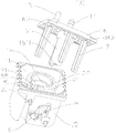
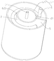
- FIG. 1 is a schematic structural view of a steam generator in accordance with some embodiments of the present invention.
- FIG. 2 is a plan view of the steam generator according to Figure 1;
- Figure 3 is a cross-sectional view taken along line A-A of the steam generator shown in Figure 2;
- Figure 4 is a cross-sectional view taken along line A-A of the steam generator with the elastic member and the seal removed as shown in Figure 3;
- Figure 5 is a cross-sectional view taken along line B-B of the steam generator shown in Figure 2;
- FIG. 6 is an exploded perspective view of a steam generator in accordance with further embodiments of the present invention.
- FIG. 7 is a schematic illustration of a steam generator in accordance with further embodiments of the present invention.
- FIG. 8 is a partial structural schematic view of a steam generator in accordance with further embodiments of the present invention.
- Figure 9 is a plan view of the steam generator shown in Figure 7;
- Figure 10 is a cross-sectional view taken along line C-C of the steam generator shown in Figure 9;
- FIG 11 is a partial structural view of the steam generator according to the cover body shown in Figure 7;
- Figure 12 is a plan view of the steam generator according to Figure 11;
- FIG. 13 is a partial structural view of a steam generator with a cover removed in accordance with still another embodiment of the present invention.
- Figure 14 is a partial structural view of the steam generator removed according to the scale-preventing structure shown in Figure 13;
- Figure 15 is a schematic view of the flow of fluid in the steam generator according to Figure 13;
- Figure 16 is a top plan view of a steam generator in accordance with further embodiments of the present invention.
- Figure 17 is a cross-sectional view taken along line D-D of the steam generator shown in Figure 16;
- Figure 18 is a schematic view showing the structure of the steam generator according to the cover body shown in Figure 16;
- Figure 19 is a schematic illustration of the connection of a steam generator system in accordance with an embodiment of the present invention.
- Water tank 200 Water tank 200; water pump 300; demineralizer 400.
- a steam generator system 1000 in accordance with an embodiment of the present invention will now be described with reference to Figs.
- Steam generator The system 1000 can be used in household appliances such as vacuum cleaners, ironing machines, range hoods, coffee machines, washing machines, air conditioners or microwave ovens for generating steam.
- a steam generator system may include a steam generator 100, a water tank 200, a water pump 300, and a demineralizer 400.
- the water pump 300 is a positive displacement pump or a vane pump.
- the steam generator 100 can include a housing 1 and a heating element 3 that can be disposed within the housing 1 to facilitate heating of water within the housing 1.
- the housing 1 has a water inlet 13 and a steam outlet 14 to facilitate water supply to the housing 1 through the water inlet 13, and the heating element 3 heats the water in the housing 1 to vaporize the water into steam and discharge it from the steam outlet 14.
- the water pump 300 is connected between the water tank 200 and the water inlet 13, and the water tank 200, the water pump 300, and the water inlet 13 of the steam generator 100 communicate to form an water inlet pipe, thereby facilitating the flow to the steam generator 100. Pumped into the water.
- the demineralizer 400 is connected in series in the water inlet line.
- the water entering the steam generator 100 is demineralized water, so that during use of the steam generator 100,
- the scale in the steam generator 100 can be greatly reduced, and the steam generator 100 is not required to be descaled, which not only saves cost, but also prolongs the service life of the steam generator 100, and also improves the steam generator 100.
- the safety of use extends the life of the steam generator system 1000.
- the steam generator system 1000 softens the water in the water inlet pipe by connecting the demineralizer device 400 in series in the water inlet pipe, so that the water entering the steam generator 100 is demineralized water, thereby During the use of the steam generator 100, the scale in the steam generator 100 can be greatly reduced, and the steam generator 100 is not required to be descaled, which not only saves cost but also prolongs the use of the steam generator 100. The service life also increases the safety of the use of the steam generator 100, thereby extending the life of the steam generator system 1000.
- the demineralizer 400 is disposed within the water tank 200 to soften the water within the water tank 200.
- the demineralizer 400 may be connected in series between other places in the water inlet pipe, such as the water pump 300 and the water inlet 13 of the steam generator 100.
- the demineralizer 400 is a softened resin or reverse osmosis membrane. Thereby, the softening effect on the water in the water inlet pipe is increased to remove the scale in the water to a large extent.
- the water pump 300 when the steam generator 100 is in operation, continuously pumps water within the water tank 200 into the housing 1 of the steam generator 100, and the heating element 3 continues to heat. Specifically, the flow rate of the water pump 300 is V. When the steam generator 100 operates, the water pump 300 continuously pumps the water in the water tank 200 into the casing 1 at a flow rate of 20 ml/min ⁇ V ⁇ 100 ml/min.
- the water in the water tank 200 is continuously pumped into the casing 1 at a flow rate of 20 ml/min ⁇ V ⁇ 100 ml/min to facilitate the flow into the casing 1
- the water inside is rapidly vaporized into water vapor and discharged from the steam outlet 14 under the heating of the heating element 3.
- This aspect not only facilitates the addition of water, but also saves the warm-up time of the steam generator 100, ensuring that the steam outlet 14 is continuously
- the steam is discharged, the working efficiency of the steam generator 100 is improved, and on the other hand, the water level sensor and the wiring are arranged in the steam generator 100, thereby saving cost, facilitating assembly of the production worker, and improving steam.
- the safety performance of the generator system 1000 is operated, the water in the water tank 200 is continuously pumped into the casing 1 at a flow rate of 20 ml/min ⁇ V ⁇ 100 ml/min to facilitate the flow into the casing 1
- the water inside is rapidly vaporized into water vapor and discharged from the steam
- the water pump 300 continuously pumps the water in the water tank 200 into the casing 1 at a flow rate of 20 ml/min ⁇ V ⁇ 100 ml/min
- the "continuous” may include continuous non-stop, that is, continuous, or three consecutive embodiments of equal time intervals or unequal time intervals.
- the power of the heating element 3 is P, and when 1000 W ⁇ P ⁇ 2500 W, 20 ml/min ⁇ V ⁇ 100 ml/min.
- the degree of cooperation between the heating element 3 and the water pump 300 is further optimized to avoid overflow of water in the casing 1 due to too low power of the heating element 3 and too much water pumped into the casing 1 by the water pump 300.
- the power of the heating element 3 is too large, and the water pumped by the water pump 300 is too small to cause problems such as dry burning of the heating element 3, thereby further improving the safety of the use of the steam generator system 1000.
- the water pump 300 continuously pumps the water in the water tank 200 into the casing 1, and the heating element 3 is continuously heated. That is, as long as the steam generator 100 starts to operate, the water pump 300 continuously continues to feed the water pump 300 in the water tank 200 into the casing 1 and the heating element 3 continues to be heated without interruption.
- the present invention is not limited thereto.
- the water pump 300 may pump the water in the water tank 200 into the casing 1 at a predetermined time interval or at different time intervals, the heating element. 3 keep heating.
- the water pump 300 can pump a predetermined amount of water into the casing 1 every 5 minutes, and the heating element 3 continues to heat, even when the water pump 300 pumps a predetermined amount of water to the casing 1, and stops pumping, the heating element 3 is always heated.
- the time parameter of the water pump 300 or the like in the time interval or the unequal time interval of the water pump 200 into the casing 1 can be adaptively adjusted according to actual needs.
- the housing 1 has a sealed cavity therein, and the heating element 3 or the like is disposed in the sealed cavity.
- the heating element 3 comprises an electrical terminal 31, and the electrical terminal 31 of the heating element 3 is exposed through a perforation formed in the housing 1.
- a partition wall 2 is formed in the casing 1 to define the outer chamber 11 and the inner chamber 12 which are spaced apart from each other.
- an annular dividing wall 2 is provided in the cavity of the housing 1 to space the outer chamber 11 and the inner chamber 12, and the outer chamber 11 surrounds the inner chamber 12.
- the partition wall 2 disposed in the casing 1 is advantageous for increasing the internal surface area of the casing 1, thereby facilitating the attachment of more scale, and to some extent avoiding the effectiveness of the steam generator 100 due to excessive scale. Reducing or even damaging the service life of the steam generator 100.
- At least one communication groove 21 that fluidly connects the outer chamber 11 and the inner chamber 12 is formed in the partition wall 2.
- a communication groove 21 is provided in the partition wall 2 to facilitate fluid communication between the outer chamber 11 and the inner chamber 12.
- the present invention is not limited thereto, and a plurality of communication grooves 21, for example, two, three, and the like may be disposed on the partition wall 2 to facilitate fluid communication between the outer chamber 11 and the inner chamber 12.
- the partition wall 2 is provided with a communication groove 21.
- the housing 1 has a water inlet 13 and a steam outlet 14, wherein the water inlet 13 is in communication with the outer chamber 11, and the steam outlet 14 is in communication with the inner chamber 12, whereby by providing a cavity spaced apart from each other within the housing 1
- the chamber 12 and the outer chamber 11 simultaneously allow the water inlet 13 to communicate directly with the outer chamber 11, the steam outlet 14 in direct communication with the inner chamber 12, and the steam outlet in communication with the inner chamber 12 during use of the steam generator 100. 14
- the water can be pumped into the outer chamber 11 by the water pump, thereby avoiding the inconvenience of adding water in the existing boiler type steam generator, and compared with the existing large-sized boiler type steam generator.
- the steam generator 100 of the present invention has a small volume, and is beneficial to the household when the steam generator 100 is installed in the household appliance with the steam generator system 1000. Miniaturization of electrical appliances.
- the water inlet 13 may be provided at any position of the top wall of the casing 1 corresponding to the outer chamber 11.
- a heating element 3 is provided on the partition wall 2 to heat the inner chamber 12 and the outer chamber 11.
- the provision of the heating element 3 on the partition wall 2 facilitates the rapid transfer of thermal energy generated by the heating element 3 to the fluid in the inner chamber 12 and the outer chamber 11, so that the liquid fluid is rapidly vaporized into a vapor after being heated.
- the fluid increases the utilization of the electrical energy while also avoiding local overheating of the heating element 3.
- the heating element 3 may be embedded in the partition wall 2, the inner wall surface or the outer wall surface of the partition wall 2 to facilitate heating of the inner chamber 12 and the outer chamber 11.
- the heating element 3 may be integrally formed in the partition wall 2 or fixedly disposed on the inner wall surface or the outer wall surface of the partition wall 2 based on a casting process to heat the inner chamber 12 and the outer chamber 11.
- the present invention is not limited thereto, and the heating element 3 may be disposed at other positions of the housing 1 such as in the inner chamber 12 or the outer chamber 11 or the heating element 3 may be integrally molded into the housing 1 by a casting process. Any part. It can be understood that the partition wall 2 provided in the casing 1 has a function of heat conduction.
- the water pump 300 pumps the water in the water tank 200 into the outer chamber 11 at a flow rate of 20 ml/min ⁇ V ⁇ 100 ml/min, and the water entering the outer chamber 11 is vaporized by heating of the heating element 3. .
- the heating element 3 simultaneously acts on the inner chamber 12 to enter the water in the inner chamber 12.
- the steam is dried into dry steam and discharged from the steam outlet 14.
- the heating element 3 heats the inner chamber 12 and the outer chamber 11, and water is pumped into the outer chamber 11 by the water pump 300 to facilitate the flow of steam from the steam outlet 14.
- the continuous discharge eliminates the utilization of the heating element 3 and shortens the warm-up time of the steam generator 100, so that the steam generator 100 can continuously generate steam having a high temperature and a large dryness.
- the housing 1 includes a base 15 and a cover 16 for sealing the base 15.
- the above-described cavity is provided in the base 15 and the top of the base 15 is open, and the cover 16 closes the base 15 to seal the cavity.
- a partition wall 2 is provided in the base 15 to define the outer chamber 11 and the inner chamber 12.
- the water inlet 13 and the steam outlet 14 are both disposed on the cover 16, which not only has a simple structure, but also facilitates the arrangement of the heating element 3 and the partition wall 2 in the casing 11.
- the invention is not limited thereto, and the water inlet 13 and the steam outlet 14 may also be provided at other implementable positions of the casing 1, for example, the water inlet 13 and the steam outlet 14 are provided on the base 15, or the water inlet 13 and the steam outlet. 14 is respectively disposed on the base 15 and the cover 16 and other layout positions that can achieve the above-mentioned equivalent effects.
- the cover 16 is sealed to the base 15 by fasteners such as bolts.
- the bottom wall of the cover body 16 is provided with a rib 162
- the top wall of the partition wall 2 is provided with a generally annular groove 22 when the cover body 16 is covered on the base 15.
- the rib 162 is engaged with the recess 22, and the cover 16 and the base 15 are further connected by fasteners, thereby further improving the sealing of the connection between the cover 16 and the base 15.
- the top wall of the casing 1 is the cover body 16, the side wall of the casing 1 is the side wall of the base 15, the bottom wall of the casing 1 is the bottom wall of the base 15, and the cavity of the casing 1 is the base.
- the cavity of 15 and the cavity of the base 15 are sealed by the cover 16.
- the cover 16 may further have a cavity, so that the cavity of the cover 16 is sealed and assembled with the cavity in the base 15 to define a cavity, that is, the housing 1 is composed of upper and lower chambers. Sealed and assembled.
- At least one fluid passage is defined between the outer chamber 11 and the inner chamber 12. That is, at least one fluid passage is provided outside the partition wall 2 and located inside the outer chamber 11.
- the partition wall 2 is annular
- the outer chamber 11 defines a plurality of fluid passages through a plurality of annular partition plates (not shown), and the plurality of fluid passages are annular passages distributed in the radial direction of the partition wall 2. Multiple fluid passages are connected.
- a fluid passage is provided between the outer chamber 11 and the inner chamber 12. It will be understood that a fluid passage provided between the outer chamber 11 and the inner chamber 12 is the passage of the outer chamber 11.
- a barrier wall 5 is provided in at least one of the fluid passages to block the flow of the fluid. That is, the barrier wall 5 is provided in at least one fluid passage to block the flow of a fluid such as water vapor.
- a plurality of fluid flows are provided between the inner chamber 12 and the outer chamber 11, and the barrier wall 5 is disposed in one of the fluid passages.
- a fluid flow is provided between the inner chamber 12 and the outer chamber 11, and the barrier wall 5 is disposed in the inner chamber 12 and the outer chamber 11. between.
- the barrier wall 5 is disposed adjacent to the communication groove 21, thereby functioning to block the flow of the fluid.
- a fluid flow is provided between the inner chamber 12 and the outer chamber 11, and the barrier wall 5 is disposed in the outer chamber 11 and outside the partition wall 2.
- the barrier wall 5 is provided in the outer chamber 11 to configure the outer chamber 11 into a C-shape.
- the barrier wall 5 is provided in the outer chamber 11 to configure the cross section of the outer chamber 11 to be substantially C shape.
- the barrier wall 5 is provided in the outer chamber 11 to configure the cross section of the outer chamber 11 into a substantially equivalent C-shape.
- the barrier wall 5 may be integrally formed with the housing 1 and the partition wall 2. Specifically, the four end walls of the barrier wall 5 are respectively connected to the housing 1 and the partition wall 2 and integrally formed. For example, a portion of the side wall of the housing is recessed into the outer chamber 11 toward the center of the housing 1 to define a barrier wall 5.
- the invention is not limited thereto, and the barrier wall 5 and the housing 1 may also be two independently formed structures, for example, the barrier wall 5 is welded in the outer chamber 11.
- the barrier wall 5 includes a first end wall 51, a second end wall 52, a third end wall 53, and a fourth end wall 54.
- the first end wall 51 is integrally connected with the bottom of the housing 1 (the bottom of the base 15)
- the second end wall 52 is integrally connected with the side wall of the housing 1 (the side wall of the base 15)
- the third end wall 53 is The outer side wall of the partition wall 2 is integrally connected
- the fourth end wall 54 is a top wall of the blocking wall 5
- the fourth end wall 54 is formed with a sealing groove 55 communicating with the groove 22 at the top of the partition wall 2, the housing 1
- the inner top wall (the bottom wall of the cover body 16) is formed with a rib 163 connected to the above-mentioned rib 162.
- the groove 55 is such that the barrier wall 5 blocks the flow of a fluid such as water vapor in
- the electrical terminal 31 of the heating element 3 is embedded in the barrier wall 5 and exposed through the perforations on the side walls of the housing 1 corresponding to the barrier wall 5.
- the barrier wall 5 is integrally formed with the housing 1 and the partition wall 2
- the electrical terminal 31 of the heating element 3 provided on the partition wall 2 is embedded in the housing in which the barrier wall 5 is disposed, and the corresponding position of the barrier wall 5 1
- the side wall is provided with a perforation, and the electrical terminal 31 is exposed through the through hole and used for electrical connection.
- the terminals of the heating element 3 are cleverly embedded in the barrier wall 5, which not only has a simple structure, but also avoids complicated wiring layout in the casing 1.
- the housing 1 and the partition wall 2 and the barrier wall 5 formed in the housing 1 may each be a cast aluminum piece.
- the water inlet 13 is located on the side of the barrier wall 5 facing away from the communication groove 21, that is, the water inlet 13 and the communication groove 21 are respectively located on both sides of the barrier wall 5.
- the water flowing into the outer chamber 11 from the water inlet 13 is vaporized into water vapor having a small degree of dryness by the heating of the heating element 3, and the water vapor is caused to flow along the outer cavity due to the action of the barrier wall 5.
- the chamber 11 and the circumference of the outer peripheral wall surrounding the partition wall 2 reach the communication groove 21, and enter the inner chamber 12 through the communication groove 21, and when the water vapor enters the inner chamber 12, it is heated and dried again, further water vapor
- the converted steam is discharged from the steam outlet 14.
- the contact area of the water vapor with the inner and outer surfaces of the partition wall 2 and the inner surface of the casing 1 is increased, and the local heating of the heating element 3 provided on the partition wall 2 is prevented, which is advantageous for improving the partition wall 2 and heating.
- the service life of the component 3 increases the heating efficiency of the heating element 3 while further reducing the warm-up time of the steam generator 100, and is also advantageous for increasing the dryness of the steam.
- the steam generator 100 includes a first inlet pipe 61 that communicates with the water inlet 13, and the water outlet end of the first inlet pipe 61 projects into the outer chamber 11.
- the water outlet end of the first inlet pipe 61 projects downward into the outer chamber 11.
- the water outlet end of the first inlet pipe 61 and the communication groove 21 are respectively located on both sides of the barrier wall 5, and water flowing out from the outlet end of the first inlet pipe 61 flows in the outer chamber 11 while being heated by the heating element 3.
- the water vapor having a small dryness needs to pass around the partition wall 2 to enter the inner chamber 12 through the communication groove 21.
- the contact area of the water vapor with the inner and outer surfaces of the partition wall 2 and the inner surface of the casing 1 is increased, and the local heating of the heating element 3 provided on the partition wall 2 is prevented, which is advantageous for improving the partition wall 2 and heating.
- the service life of the component 3 increases the heating efficiency of the heating element 3 while further reducing the warm-up time of the steam generator 100, and is also advantageous for increasing the dryness of the steam.
- the water inlet 13 and the communication groove 21 are located on the same side of the barrier wall 5.
- the steam generator 100 includes a second inlet pipe 62 communicating with the water inlet port 13, and the free end of the second inlet pipe 62 is from the barrier groove 5 adjacent to the communication groove 21.
- One side extends around the circumferential direction of the partition wall 2 to the other side of the barrier wall 5.
- the present invention is not limited thereto, and the inlet pipe may be formed in other shapes, for example, the water inlet end of the inlet pipe is in communication with the water inlet 13, and the other end of the inlet pipe is disposed around the circumferential direction of the partition wall 2 a plurality of times.
- the other end of the inlet pipe may be spirally wound in the circumferential direction of the partition wall 2.
- the second inlet pipe 62 has a plurality of spaced-apart first water outlet holes 621 , whereby water flowing out of the plurality of first water outlet holes 621 can be sprayed on the outer circumference of the partition wall 2 .
- a water flow or a water film is formed on the outer peripheral wall of the partition wall 2, and the water flow or the water film flows downward along the outer peripheral wall of the partition wall 2, thereby allowing sufficient heat exchange between the liquid water and the heating element 3, and The first water outlet hole 621 of the second inlet pipe 62 away from the communication groove 21
- the water vapor generated by the ejected water needs to pass around the outer peripheral wall of the partition wall 2 to enter the inner chamber 12 through the communication groove 21, thereby facilitating the heating efficiency of the heating element 3 and reducing the warm-up of the steam generator 100.
- a plurality of first water outlet holes 621 are evenly spaced on a side of the second water inlet pipe 62 near the partition wall 2, so that water flowing out of the first water outlet hole 621 is sprayed on the partition wall 2 as much as possible.
- the heating element 3 In order to facilitate the heating of the heating element 3. It can be understood that the above advantages can be further optimized when the plurality of first water outlet holes 621 on the second inlet pipe 62 are very small and sprayed with misty water droplets.
- the free end of the second inlet pipe 62 is the outlet end, whereby the outlet end of the second inlet pipe 62 and the communication groove 21 are spaced apart by the barrier wall 5, from the second inlet pipe 62.
- the water flowing out from the outlet end becomes water vapor under the heating of the heating element 3, it takes a week around the outer peripheral wall of the partition wall 2 to enter the inner chamber 12 through the communication groove 21, in the process, water is added.
- the contact area between the steam and the inner and outer surfaces of the partition wall 2 and the inner surface of the casing 1 avoids local overheating of the heating element 3 provided on the partition wall 2, which is advantageous for improving the service life of the partition wall 2 and the heating element 3, and improving The heating efficiency of the heating element 3, while further reducing the warm-up time of the steam generator 100, is also advantageous for increasing the dryness of the steam.
- the second inlet pipe 62 includes a C-shaped pipe section 622 and a vertical pipe section 623 that is perpendicular to the C-shaped pipe section 622 and connected to the water inlet port 13, and has a simple structure. Further, the second inlet pipe 62 surrounds the outer side of the upper outer wall surface of the partition wall 2, whereby at least a part of the water discharged from the second inlet pipe 62 can be sprayed on the outer side of the upper outer wall surface of the partition wall 2, along The partition wall 2 flows downward, thereby facilitating sufficient heat exchange with the heating element 3, improving the heating efficiency of the heating element 3, while also avoiding the local overheating of the heating element 3 to some extent.
- the present invention is not limited thereto, and the second inlet pipe 62 may surround other positions in the height direction of the partition wall 2, for example, the second inlet pipe 62 surrounds the outer side of the outer wall surface of the central portion of the partition wall 2 or the outer side of the lower outer wall surface.
- the steam generator 100 further includes a third water inlet pipe (not shown) that communicates with the water inlet port 13, and the water outlet end of the third water inlet pipe extends through the barrier wall 5 into the outer cavity.
- the contact area of the water vapor with the inner and outer surfaces of the partition wall 2 and the inner surface of the casing 1 is increased, and the local heating phenomenon of the heating element 3 provided on the partition wall 2 is avoided, which is advantageous for improving the partition wall 2 and the heating element.
- the service life of 3 increases the heating efficiency of the heating element 3 while further reducing the warm-up time of the steam generator 100, and is also advantageous for increasing the dryness of the steam.
- the steam generator 100 further includes a fourth inlet pipe (not shown) that communicates with the water inlet 13 , the free end of the fourth inlet pipe is closed and the fourth inlet pipe passes through the barrier wall 5 and along the partition wall 2 a circumferential direction extending, a plurality of spaced second water outlet holes (not shown) are formed in the longitudinal direction of the fourth water inlet pipe, whereby water flowing out of the plurality of second water outlet holes can be sprayed in the
- the outer peripheral wall of the partition wall 2 forms a water flow or a water film on the outer peripheral wall of the partition wall 2, and the water flow or the water film flows downward along the outer peripheral wall of the partition wall 2, thereby causing the liquid water and the heating element
- the piece 3 is sufficiently heat exchanged, and water vapor generated from water ejected from the second water outlet of the fourth inlet pipe away from the communication groove 21 needs to pass around the outer peripheral wall of the partition wall 2 to enter the inner chamber through the communication groove 21.
- a plurality of second water outlet holes are evenly spaced on a side of the fourth water inlet pipe adjacent to the partition wall 2, so that water flowing out of the second water outlet hole is allowed to be sprayed on the partition wall 2 as much as possible. It can be understood that the above advantages can be further optimized when a plurality of second water outlet holes on the fourth inlet pipe are very small and sprayed with misty water droplets.
- water vapor formed in the outer chamber 11 enters the inner chamber 12 through the communication groove 21 to form a vapor cyclone flow.
- the extending direction of the communication groove 21 is tangential to the inner peripheral wall surface of the inner chamber 12 to form water vapor in the outer chamber 11 tangentially entering the inner chamber 12, thereby forming a steam cyclone flow.
- the water vapor in the outer chamber 11 is tangentially entered into the inner chamber 12 through the communication groove 21, and a cyclone is formed in the inner chamber 12.
- the air flow causes the water vapor to contact the inner wall surface of the inner chamber 12, and the cyclone air flow forms an effect similar to the cyclone, so that the liquid water in the water vapor is rapidly vaporized toward or along the inner wall of the inner chamber 12. It flows downward and further forms steam under the heating of the heating element 3.
- the preheating time of 100 increases the temperature and dryness of the steam at the steam outlet 14, and on the other hand, the scale in the water vapor is smashed toward the inner wall surface of the inner chamber 12 and adheres to the inner wall surface of the inner chamber 12, thereby To some extent, the possibility of scale removal from the steam outlet 14 is reduced, and the damage caused by the scale blocking the steam outlet 14 is avoided.
- the communication groove 21 is formed at an upper portion of the partition wall 2 and adjacent to a top wall of the casing 1 (for example, adjacent to the cover body 16).
- the steam generator 100 further includes a boost switch device 4 disposed at the steam outlet 14 to allow water vapor from the base 15 to exit the steam 14 one-way discharge.
- the booster switching device 4 disposed at the steam outlet 14 allows the steam in the housing 1 to be discharged from the steam outlet 14 at a constant high pressure. Specifically, when the heating element 3 is heated, the liquid water in the casing 1 is continuously vaporized into water vapor. During this process, the pressure inside the casing 1 is continuously increased. When the pressure in the casing 1 is greater than the set value, the booster switching device 4 is opened to facilitate the rapid discharge of the dried steam from the steam outlet 14.
- the boost switch device 4 When the pressure in the casing 1 is reduced to be equal to or less than the set value, the boost switch device 4 is turned off until the pressure in the casing 1 reaches the set value again, and the boost switch device 4 is turned on.
- the booster switching device 4 disposed at the steam outlet 14 can maintain a constant pressure throughout the housing 1, which not only helps to further increase the saturation temperature of the steam in the housing 1 to increase the steam at the steam outlet 14.
- the temperature and the dryness are also favorable for increasing the discharge speed of the water vapor, ensuring that the water vapor is continuously discharged from the steam outlet 14, and the phenomenon that the steam of the steam outlet 14 is continuously attenuated is avoided.
- the pressure setting value in the casing 1 is related to the weight of the boost switch device 4, and therefore, the pressure setting value in the casing 1 can be adjusted by adjusting the weight of the boost switch device 44.
- the cover body 16 extends downwardly from the protruding column 161, and the protruding column 161 defines a unidirectional passage 1612 having a passage opening 1611 at the bottom, and the upper end of the unidirectional passage 1612 and the steam outlet 14 connected, the booster switch device 4 is disposed in the unidirectional passage 1612, thereby not only having a simple structure, but also the protruding column 161 extending downward from the cover 16 increases the surface area in the casing 1 to facilitate the adhesion of scale
- the outer surface of the protruding column 161 avoids damage to the steam generator 100 due to excessive scale to a certain extent, and prolongs the service life of the steam generator 100.
- the present invention is not limited thereto, and the protruding column 161 may not be disposed on the cover 16 .
- the cross section of the protruding post 161 is formed in a circular shape, and the protruding column 161 has a smaller cross-sectional area in a direction away from the cover body 16.
- the boost switch device 4 includes a seal 41 and an elastic member 42.
- the sealing member 41 seals the passage opening 1611 under the elastic deformation force of the elastic member 42.
- the seal 41 is located in the unidirectional passage 1612 and the lower end closes the passage opening 1611, and the elastic member 42 abuts between the steam outlet 14 and the seal 41 so that the seal 41 seals the passage opening according to the elastic deformation force of the elastic member 42. 1611.
- This aspect is not only beneficial to further increase the saturation temperature of the water vapor in the casing 1 to increase the temperature and dryness of the steam at the steam outlet 14, but also to improve the discharge speed of the water vapor, and to ensure the steam from the steam outlet 14 Continuous discharge, avoiding the phenomenon that the steam continues to attenuate; on the other hand, the elastic member 42 and the sealing member 41 can also block the scale and liquid water in the water vapor from being blocked in the casing 1, which can prevent the scale from being discharged with the water vapor. The clogging of the piping caused by the piping connected to the steam outlet 14 further improves the dryness of the water vapor discharged from the steam outlet 14.
- the set value of the pressure in the housing 1 is related to the weight of the elastic member 42 and the sealing member 41, the elastic modulus of the elastic member 42 and the deformation length, and therefore, the elastic member 42 and the sealing member can be adjusted.
- the sealing member 41 may be in the shape of a sphere, a cylinder, a cone or a rectangular parallelepiped. Of course, it is understood that the sealing member 41 may have other shapes as long as the passage opening 1611 can be closed and opened.
- the seal 41 may be a piston and the resilient element 42 is a spring.
- the boost switch device 4 includes a one-way valve plate disposed at the steam outlet 14.
- the boost switch device 44 can be a one-way valve plate to allow steam within the housing 1 to be vented unidirectionally from the steam outlet 14, a simple construction.
- the heating element 3 can simultaneously heat the inner chamber 12 and the outer chamber 11, that is, during the entire operation of the heating element 3, the heating element 3 always faces the inner chamber 12 and The outer chamber 11 is simultaneously heated.
- the present invention is not limited thereto, and when the heating element 3 is just starting to operate, the heating element 3 does not simultaneously heat the inner chamber 12 and the outer chamber 11, and after a period of time, the heating element 3 pairs the inner chamber 12 and the outer chamber. 11 simultaneous addition heat.
- the heating element 3 first heats the outer chamber 11 so that the water in the outer chamber 11 can become water as quickly as possible under the heating of the heating element 3.
- the heating element 3 After the steam enters the inner chamber 12, after a period of time (for example 5S), the heating element 3 simultaneously heats the inner chamber 12 and the outer chamber 11 so that the heating element 3 continues to heat the water in the outer chamber 11 and into the interior. The water vapor in the chamber 12 continues to be heated, thereby increasing the dryness of the water vapor discharged from the steam outlet 14.
- a period of time for example 5S
- the steam generator 100 further includes at least one gain structure 7.
- the gain structure 7 is housed within the inner chamber 12 and/or the outer chamber 11, for example the gain structure 7 may be housed only within the inner chamber 12, or the gain structure 7 may be housed only within the outer chamber 11, or the gain structure 7 may comprise A plurality of and respectively accommodated in the inner chamber 12 and the outer chamber 11.
- the gain structure 7 is such that the service life of the steam generator 100 is increased to some extent, and it is also advantageous to block the flow of scale with water vapor to reduce the possibility of scale flowing out of the steam outlet 14.
- the gain structure 7 is in contact with the partition wall 2, whereby the heat generated by the heating element 3 can be facilitated to be transferred to the gain structure 7 to facilitate heat exchange between the gain structure 7 and the water vapor and/or water flowing through the gain structure 7, Thereby increasing the heat exchange area, which is advantageous for improving the utilization rate of the heat of the heating element 3, reducing the working time of the heating element 3 to a certain extent, prolonging the life of the heating element 3 and indirectly prolonging the service life of the steam generator 100, It is also beneficial to increase the temperature and dryness of the water vapor.
- the gain structure 7 is not in contact with the inner side wall of the outer chamber 11 (i.e., the inner side wall of the housing 1 / the inner side wall of the base 15), thereby avoiding to some extent the inner side walls of the gain structure 7 and the outer chamber 11
- the heat is radiated to the outside of the steam generator 100 by contact.
- the invention is not limited thereto, and the gain structure 7 can be simultaneously connected to the outer side wall of the partition wall 2 and the inner side wall of the outer chamber 11.
- the gain structure 7 is connected to the partition wall 2.
- the gain structure 7 and the partition wall 2 are integrally formed, and the structure is simple.
- the present invention is not limited thereto, and the gain structure 7 may also be disposed on the top wall of the casing 1 (for example, the cover 16), and the gain structure 7 extends downward into the inner chamber 12 and/or the outer chamber 11, And in contact with the partition wall 2.
- the lower end of the gain structure 7 is spaced apart from the bottom wall of the casing 1 to facilitate the circulation of water at the bottom of the casing 1 (the bottom of the cover 16) and the flow of scale, avoiding the lower end of the gain structure 7.
- Contact with the bottom wall of the casing 1 causes scale to accumulate at this position.
- the cross section of the gain structure 7 is formed into a substantially "ten" shape, and the cross sectional area of the gain structure 7 is gradually decreased in the direction from top to bottom.
- the invention is not limited to the fact that the gain structure 7 can also be formed in other shapes, such as a plate shape extending up and down.
- the gain structure 7 includes a plurality, and a plurality of gain structures 7 are disposed around the circumference of the partition wall 2. Specifically, a plurality of gain structures 7 are disposed around the circumferential direction of the partition wall 2. For example, the gain structure 7 includes four, and the four gain structures 7 are housed in the outer chamber 11 and evenly spaced in the circumferential direction of the partition wall 2. It will be appreciated that the size and shape between the plurality of gain structures 7 may be the same or different.
- the steam generator 100 further includes at least one dirt containment structure disposed within the inner chamber 12 and/or the outer chamber 11.
- the dirt holding structure is only provided in the inner chamber 12, or the scale-preventing structure is provided only in the outer chamber 11, or the plurality of scale-preventing structures are provided in the outer chamber 11 and the inner chamber 12, respectively.
- the fouling structure it is advantageous not only to increase the surface area in the inner chamber 12 and/or the outer chamber 11, so that more scale adheres to the scale-preventing structure, thereby improving the steam generator 100 to a certain extent.
- the service life but also helps to block the flow of scale with water vapor to reduce the possibility of scale flowing out of the steam outlet 14.
- the dirt holding structure is at least one of a mesh grill 81, a strip grill 82, and a column grill 83.
- the dirt-preventing structure is a mesh grill 81, thereby not only facilitating the increase of the surface area in the casing 1, so that more scale adheres to the mesh grill 81.
- the service life of the steam generator 100 is increased to some extent, and the mesh on the mesh grill 81 can also block the flow of scale with water vapor to reduce the possibility of scale flowing out of the steam outlet 14, while the mesh grille
- the arrangement of 81 also avoids the setting of the screen at the steam outlet 14, thereby avoiding the clogging of the steam outlet 14 and the scale on the filter screen caused by the scale depositing on the filter screen due to the provision of the filter screen at the steam outlet 14 in the prior art. Problems such as clogging of the pipe caused by the flow of water vapor to the external pipe communicating with the steam outlet 14.
- the mesh of the mesh grill 81 may be formed as a circular hole, or a hexagonal hole, or a hole of other shapes, which is not limited in the present invention. It can be understood that the sizes of the plurality of meshes on the mesh grill 81 may be the same, and may of course be different. Alternatively, the size of the mesh on the mesh grill 81 can be adjusted. For example, the size of the mesh on the mesh grill 81 can be adjusted according to the water quality and working conditions of each area.
- the mesh grill 81 may comprise a plurality, and the plurality of mesh grills 81 are spaced apart within the chamber in which they are located (ie, the outer chamber 11 and/or the inner chamber 12). For example, as shown in FIGS. 13 and 15, three mesh grills 81 are spaced apart from each other in the outer chamber 11, thereby increasing the scale attachment area to a greater extent, and also blocking the flow of scale with water vapor to a greater extent. To reduce the possibility of scale flowing out of the steam outlet 14.
- the scale-preventing structure is a strip-shaped grid 82, thereby not only facilitating the increase of the surface area in the housing 1, so that more scale adheres to the strip-shaped grid 82,
- the service life of the steam generator 100 is increased to some extent, and the flow of scale with water vapor is also blocked to reduce the possibility of scale flowing out of the steam outlet 14, while the arrangement of the strip grid 82 also avoids the steam outlet 14
- the arrangement of the filter net avoids the clogging of the steam outlet 14 caused by the scale attached to the filter net due to the provision of the filter screen at the steam outlet 14 in the prior art and the flow of scale on the filter net under the impact of water vapor to Problems such as clogging of the external piping caused by the external piping that the steam outlet 14 communicates with.
- each of the grid holes of the strip grid 82 extends in the height direction of the strip grid 82, when the strip grid 82 blocks the scale, the scale is deposited downward in the strip under the action of gravity.
- the bottom of the grille 82 reduces the probability of the strip grille 82 being blocked by scale, and ensures the flow area of the water vapor on the strip grid 82, so that the water vapor does not flow when flowing through the strip grid 82.
- the scale is prevented from rushing out of the steam outlet 14 with the steam.
- the size and number of the grid holes on each strip grid 82 can be adjusted.
- the size of the grid holes can be adjusted according to the water quality and working conditions of each area.
- the strip grid 82 may comprise a plurality, and the plurality of strip grids 82 are spaced apart within the chamber in which they are located (ie, the outer chamber 11 and/or the inner chamber 12).
- the plurality of strip grids 82 are spaced apart within the chamber in which they are located (ie, the outer chamber 11 and/or the inner chamber 12).
- three strip-shaped gratings 82 are spaced apart in the outer chamber 11, thereby increasing the attachable area of the scale to a greater extent, and also blocking the scale with water to a greater extent.
- the flow of steam reduces the likelihood of scale flowing out of the steam outlet 14.
- a mesh grill 81 and/or a strip grill 82 are disposed in the outer chamber 11, and both ends of the mesh grill 81 and/or both ends of the strip grill 82 are respectively associated with the outer chamber 11
- the inner side wall is connected to the outer side wall of the partition wall 2.
- the two ends of the mesh grill 81 are respectively connected to the inner side wall of the outer chamber 11 and the outer side wall of the partition wall 2, when only the outer chamber 11 is inside.
- both ends of the strip grill 82 and the mesh grill 81 are respectively connected to the inner side wall of the outer chamber 11 and the outer side wall of the partition wall 2.
- the inner side wall of the outer chamber 11 and the outer side wall of the partition wall 2 are respectively formed with a first card slot 84 and a second card slot 85, both ends of the mesh grill 81 and/or strips. Both ends of the grid 82 are respectively locked in the first card slot 84 and the second card slot 85, whereby the mesh grill 81 and/or the strip grill 82 can be reliably fixed in the outer chamber 11 It is avoided that the mesh grille 81 and/or the strip grille 82 are moved or shaken in the outer chamber 11 due to the insufficiency of the mesh grille 81 and/or the strip grille 82 to affect the mesh grille 81 and / or the use effect of the strip grille 82.
- both the first snap groove and the second slot 85 extend in the height direction of the housing 1 (ie, the height direction of the base 15), thereby the strip grille 82 and/or The mesh grill 81 is reliably fixed between the outer chamber 11 and the partition wall 2.
- the first card slot 84 is defined by two first protruding ribs that project from the inner side walls of the outer chamber 11 and are spaced apart from each other.
- the second card slot 85 is defined by two second protruding ribs projecting from the outer side walls of the partition wall 2 and spaced apart from each other, and the structure is simple and reliable.
- the second protruding rib and the partition wall 2 and between the first protruding rib and the housing 1 may be an integrally formed piece.
- the columnar grid 83 is located within the outer chamber 11 and/or the inner chamber 12, and the column grid 83 includes a plurality of generally radially extending Extension bars 831. This not only helps to increase the surface area in the outer chamber 11 and/or the inner chamber 12, so that more scale adheres to the extension strip 831, and the service life of the steam generator 100 can be improved to some extent. Moreover, the arrangement of the extension strips 831 can also block the flow of scale with water vapor to some extent to reduce the likelihood of scale flowing out of the steam outlet 14.
- the columnar grid 83 includes a plurality of extending strips 831 distributed along the height direction of the casing 1, and each of the extending strips 831 includes a plurality of circumferentially distributed (for example, distributed along the circumferential direction of the dividing wall 2), whereby, the surface area in the outer chamber 11 and/or the inner chamber 12 can be increased to a greater extent in order to accommodate more scale, and at the same time, it is advantageous to block the scale from flowing with water vapor to improve steam generation. The service life of the device 100.
- the adjacent two-strand extension strips 831 are staggered from each other in the height direction, for example, the plurality of loop extension strips 831 distributed in the height direction of the casing 1 (for example, the height direction of the base 15) are shifted from each other.
- the probability that the scale hits the extension bar 831 can be increased to a greater extent, thereby blocking the flow of the scale with the water vapor to further prevent the scale from being flushed out of the steam outlet 14 with the water vapor.
- the steam outlet 14 is clogged or blocked by a line connected to the steam outlet 14, thereby increasing the service life of the steam generator 100.
- the extension strip 831 extends from the outer side wall and/or the inner side wall of the partition wall 2, for example, when the column grid 83 is disposed in the inner chamber 12, the extension strip 831 is from the inner side wall of the partition wall 2. Extending into the inner chamber 12 as a column When the grille 83 is disposed in the outer chamber 11, the extension strip 831 extends from the outer side wall of the partition wall 2 into the outer chamber 11, and when the column grid 83 is simultaneously disposed in the outer chamber 11 and the inner chamber 12, A plurality of extension strips 831 extend from the outer and inner sidewalls of the partition wall 2 into the outer chamber 11 and into the inner chamber 12, respectively.
- the heating element 3 spirally surrounds the circumferential direction of the partition wall 2 and is disposed within the partition wall 2.
- the heating element 3 is one and spirally surrounds the circumferential direction of the partition wall 2 and is disposed in the partition wall 2, thereby increasing the contact area of the heating element 3 with the partition wall 2, so that the heating element 3 passes through the partition wall 2 more
- the heat is radiated into the inner chamber 12 and the outer chamber 11, thereby shortening the warm-up time of the steam generator 100 and increasing the temperature and dryness of the water vapor.
- the present invention is not limited thereto, and the heating element 3 may further include a plurality of heating elements 3 spaced apart in the up and down direction of the partition wall 2.
- the steam generator 100 further includes at least one thermostat 9 that controls the operation and disconnection of the heating element 3 in accordance with the temperature of the housing 1.
- the thermostat 9 is provided on the outer surface of the casing 1.
- the thermostat 9 is provided on the outer top wall of the casing 1 (i.e., the outer top wall of the cover 16), the outer bottom wall of the casing 1 (i.e., the outer bottom wall of the base 15), or the outer side wall surface of the casing 1 ( That is, the outer side wall of the base 15).
- the thermostat 9 By arranging the thermostat 9 on the outer surface of the casing 1, the installation, maintenance and replacement of the thermostat 9 are facilitated, and the working environment of the thermostat 9 is optimized, and the thermostat 9 does not need to be Operating in a harsh environment, thereby expanding the selectable range of the thermostat 9, for example, selecting a low cost thermostat 9, is advantageous in reducing the cost of the steam generator 100.
- the thermostat 9 is an electronic thermostat 9 and is connected to a first temperature sensor, the thermostat 9 being disposed on the outer surface of the housing 1 for detecting the first temperature sensor The temperature of the housing 1 is controlled by the thermostat 9 according to the temperature detected by the first temperature sensor to control the operation and disconnection of the heating element 3.
- the thermostat 9 controls the heating element 3 to stop heating, when the first temperature sensor detects the casing 1
- the temperature controller 9 controls the heating element 3 to be heated, thereby ensuring the reliability of the use of the heating element 3, improving the safety of the use of the steam generator 100, and avoiding the temperature being excessively heated by the heating element 3.
- the high steam generator 100 is burned out and other safety hazards.
- the thermostat 9 may include a plurality of thermostats 9 connected in parallel, and the plurality of thermostats 9 may be respectively disposed at different positions on the outer surface of the casing 1 to detect different positions of the casing 1.
- the temperature at the place For example, when the first temperature sensor of one of the thermostats 9 detects that the temperature at the corresponding position of the housing 1 where the thermostat 9 is located is higher than a predetermined maximum temperature value, the thermostat 9 can control the heating element. 3 stopping heating, after stopping heating for a period of time, if the first temperature sensor of the other thermostat 9 detects that the temperature at the corresponding position of the casing 1 where the thermostat 9 is located is lower than a predetermined minimum temperature value, The thermostat 9 controls the heating element 3 to begin heating.
- the thermostat 9 is a mechanical thermostat 9 and is provided on the housing 1 which can be opened or reset depending on the temperature of the housing 1 to control the heating element 3 Work and disconnect.
- the steam generator 100 further includes at least one fuse 10 disposed on an outer surface of the housing 1.
- the fuse 10 is provided on the outer top wall of the casing 1 (ie, the outer top wall of the cover 16), the outer bottom wall of the casing 1 (ie, the outer bottom wall of the base 15), or the outer side wall surface of the casing 1 (ie, On the outer side wall of the base 15). This facilitates the installation, repair and replacement of the fuse 10.
- Each fuse 10 includes a second temperature sensor, the fuse 10 is disposed on an outer surface of the housing 1 such that the second temperature sensor detects the temperature of the housing 1, and when the second temperature sensor detects that the temperature of the housing 1 is higher than At a predetermined value, the fuse 10 controls the heating element 3 to be de-energized. Specifically, when the second temperature sensor of the fuse 10 detects that the temperature of the casing 1 is abnormally high (for example, when the steam generator 100 malfunctions and the thermostat 9 fails) and is higher than a predetermined value, the fuse 10 is blown. In order to de-energize the heating element 3 to stop heating of the heating element 3, the safety of the use of the steam generator 100 is improved.
- the fuse 10 may include a plurality of, and the plurality of fuses 10 are connected in parallel, and the plurality of fuses 10 may be disposed at different positions on the outer surface of the casing 1.
- thermostat 9 is provided on the outer wall surface of the casing 1, for example, the thermostat 9 is provided on the outer wall surface of the base 15. Alternatively, the fuse 10 and the thermostat 9 are simultaneously provided on the outer wall surface of the base 15.
- the housing 1 has a substantially square shape, a spherical shape, an ellipsoidal shape, or a cylindrical shape, and has a simple structure.
- the partition wall 2 is formed in a circular or square annular shape, that is, the cross section of the partition wall 2 is formed in a circular or square annular shape to partition the outer chamber 11 and the inner chamber 12.
- the invention is not limited thereto, and the cross section of the partition wall 2 may be formed in other shapes such as an elliptical shape.
- the steam outlet 14 is disposed corresponding to the center of the inner chamber 12.
- the present invention is not limited thereto, and the steam outlet 14 may be disposed at other positions of the top wall of the casing 1 corresponding to the inner chamber 12 (ie, the cover body 16) as long as the water vapor in the inner chamber 12 is facilitated. Just fine.
- the partition wall 2 is coaxial with the center line of the casing 1, that is, the center lines of the inner chamber 12 and the outer chamber 11 are in line, thereby facilitating the smooth flow of water vapor through the outer chamber 11 Moreover, it is also possible to facilitate the heating element 3 to uniformly heat the water vapor in the outer chamber 11.
- the centerlines of the inner chamber 12 and the outer chamber 11 can also be different lines.
- a control method of a steam generator system is described below.
- the steam generator system is the steam generator system described above, and the control method of the steam generator system comprises at least the following steps:
- S1 Power is supplied to the water pump and the heating element, respectively.
- the heating element can be realized after the steam generator is energized. Power up.
- the water pump pumps the water in the water tank into the casing through a water inlet at a flow rate of 20 ml/min ⁇ V ⁇ 100 ml/min.
- the water pump pumps the water in the water tank through the water inlet into the outer chamber communicating with the water inlet at a flow rate of 20 ml/min ⁇ V ⁇ 100 ml/min.
- the heating element vaporizes water pumped into the casing into steam and is discharged from the steam outlet.
- the heating element heats the water pumped into the outer chamber to vaporize the water into water vapor and enter the inner chamber through the communication trough, and in the inner chamber, further heating of the heating element forms dry water vapor from the steam The outlet is discharged.
- control method of the steam generator system according to the embodiment of the present invention is advantageous for improving the working efficiency of the steam generator.
- a household appliance according to an embodiment of the present invention includes the steam generator system 1000 described above.
- the home appliance according to the embodiment of the present invention prolongs the service life of the home appliance by providing the steam generator system 1000 described above.
- the household appliance is a vacuum cleaner, a ironing machine, a range hood, a coffee machine, a washing machine, an air conditioner or a microwave oven.
- the terms “installation”, “connected”, “connected”, “fixed” and the like shall be understood broadly, and may be either a fixed connection or a detachable connection, unless explicitly stated and defined otherwise. Or in one piece; it may be a mechanical connection, or it may be an electrical connection or a communication with each other; it may be directly connected or indirectly connected through an intermediate medium, and may be an internal connection of two elements or an interaction relationship between two elements. Unless otherwise expressly defined. For those skilled in the art, the specific meanings of the above terms in the present invention can be understood on a case-by-case basis.
Landscapes
- Engineering & Computer Science (AREA)
- Physics & Mathematics (AREA)
- Thermal Sciences (AREA)
- Mechanical Engineering (AREA)
- General Engineering & Computer Science (AREA)
- Life Sciences & Earth Sciences (AREA)
- Chemical & Material Sciences (AREA)
- Environmental & Geological Engineering (AREA)
- Hydrology & Water Resources (AREA)
- Water Supply & Treatment (AREA)
- Organic Chemistry (AREA)
- Sustainable Energy (AREA)
- Sustainable Development (AREA)
- Combustion & Propulsion (AREA)
- Air Humidification (AREA)
Abstract
Description
Claims (37)
- 一种蒸汽发生器系统,其特征在于,包括:水箱;蒸汽发生器,所述蒸汽发生器包括壳体和加热元件,所述壳体上具有进水口和蒸汽出口,所述加热元件设置在所述壳体内;水泵,所述水泵连接在所述水箱和所述进水口之间;软化水装置,所述水箱、所述水泵和所述蒸汽发生器的进水口连通以形成进水管路,所述软化水装置串连在所述进水管路中。
- 根据权利要求1所述的蒸汽发生器系统,其特征在于,所述软化水装置设在所述水箱内。
- 根据权利要求1-2中任一项所述的蒸汽发生器系统,其特征在于,所述水泵的流量为V,当所述蒸汽发生器工作时,所述水泵将所述水箱内的水以20ml/min≤V≤100ml/min的流量连续泵入所述壳体。
- 根据权利要求1-3中任一项所述的蒸汽发生器系统,其特征在于,所述壳体具有密封的空腔,所述壳体内形成有分隔壁以将所述空腔限定出彼此间隔的外腔室和内腔室,所述分隔壁上形成有将所述外腔室和所述内腔室进行流体连通的至少一个连通槽,所述进水口与所述外腔室连通,所述蒸汽出口与所述内腔室连通,所述加热元件设置在所述分隔壁上以对所述内腔室和所述外腔室加热;其中,所述水泵将所述水箱内的水以20ml/min≤V≤100ml/min的流量泵入所述外腔室。
- 根据权利要求4所述的蒸汽发生器系统,其特征在于,所述外腔室和所述内腔室之间限定出至少一条流体通道,在至少一条所述流体通道中设置阻隔壁以阻隔流体的流向,且所述阻隔壁邻近所述连通槽设置。
- 根据权利要求5所述的蒸汽发生器系统,其特征在于,所述进水口位于所述阻隔壁的背离所述连通槽的一侧。
- 根据权利要求6所述的蒸汽发生器系统,其特征在于,所述蒸汽发生器还包括与所述进水口连通的第一进水管,且所述第一进水管的出水端伸入所述外腔室内。
- 根据权利要求5所述的蒸汽发生器系统,其特征在于,所述进水口和所述连通槽位于所述阻隔壁相同的一侧。
- 根据权利要求8所述的蒸汽发生器系统,其特征在于,所述蒸汽发生器还包括与所述进水口连通的第二进水管,所述第二进水管的自由端从所述阻隔壁的靠近所述连通槽的一侧环绕所述分隔壁的周向方向延伸至所述阻隔壁的另一侧。
- 根据权利要求9所述的蒸汽发生器系统,其特征在于,所述第二进水管上具有多个间隔设置的第一出水孔。
- 根据权利要求9所述的蒸汽发生器系统,其特征在于,所述第二进水管的自由端 为出水端。
- 根据权利要求8所述的蒸汽发生器系统,其特征在于,所述蒸汽发生器还包括与所述进水口连通的第三进水管,所述第三进水管的出水端穿过所述阻隔壁伸入到所述外腔室的远离所述连通槽的一侧。
- 根据权利要求8所述的蒸汽发生器系统,其特征在于,所述蒸汽发生器还包括与所述进水口连通的第四进水管,所述第四进水管的自由端封闭且所述第四进水管穿过所述阻隔壁,且沿所述分隔壁的周向方向延伸,在所述第四进水管的长度方向上形成有多个间隔设置的第二出水孔。
- 根据权利要求4所述的蒸汽发生器系统,其特征在于,所述外腔室内形成的水蒸汽通过所述连通槽进入所述内腔室内后形成蒸汽旋风气流。
- 根据权利要求14所述的蒸汽发生器系统,其特征在于,所述连通槽的延伸方向与所述内腔室的内周壁面相切以形成在所述外腔室内的水蒸汽切向地进入所述内腔室内。
- 根据权利要求4所述的蒸汽发生器系统,其特征在于,所述连通槽形成于所述分隔壁的上部且邻近所述壳体顶壁。
- 根据权利要求5所述的蒸汽发生器系统,其特征在于,所述加热元件还包括电气接线端,所述电气接线端嵌入所述阻隔壁中且通过与所述阻隔壁对应的所述壳体侧壁上的穿孔外露。
- 根据权利要求5所述的蒸汽发生器系统,其特征在于,所述阻隔壁的四个端壁分别与所述壳体、所述分隔壁连接且一体成型设置。
- 根据权利要求1-18中任一项所述的蒸汽发生器系统,其特征在于,所述壳体包括:底座;和用于密封所述底座的盖体;其中,所述进水口和所述蒸汽出口均设在所述盖体上。
- 根据权利要求4所述的蒸汽发生器系统,其特征在于,所述加热元件对所述内腔室和所述外腔室同时加热。
- 根据权利要求4所述的蒸汽发生器系统,其特征在于,所述加热元件嵌入于所述分隔壁之中、所述分隔壁的内壁面或外壁面上。
- 根据权利要求19所述的蒸汽发生器系统,其特征在于,所述蒸汽发生器还包括增压开关装置,所述增压开关装置设在所述蒸汽出口处以使所述底座内的水蒸汽从所述蒸汽出口单向排出。
- 根据权利要求22所述的蒸汽发生器系统,其特征在于,所述盖体向下延伸出突出柱,所述突出柱内限定出底部具有通道口的单向通道,所述单向通道的上端与所述蒸汽出口连通,所述增压开关装置设在所述单向通道。
- 根据权利要求23所述的蒸汽发生器系统,其特征在于,所述增压开关装置包括:密封件和弹性元件,所述密封件在所述弹性元件的弹性形变作用力下密封所述通道口。
- 根据权利要求22所述的蒸汽发生器系统,其特征在于,所述增压开关装置包括设在所述蒸汽出口处的单向阀片。
- 根据权利要求4所述的蒸汽发生器系统,其特征在于,所述蒸汽发生器还包括至 少一个容垢结构,所述容垢结构设置在所述内腔室和/或所述外腔室内。
- 根据权利要求26所述的蒸汽发生器系统,其特征在于,所述容垢结构为网状格栅、条状格栅、和柱状格栅中的至少一种。
- 根据权利要求27所述的蒸汽发生器系统,其特征在于,所述网状格栅和/或所述条状格栅设在所述外腔室内,且所述网状格栅的两端和/或所述条状格栅的两端均分别与所述外腔室的内侧壁和所述分隔壁的外侧壁连接。
- 根据权利要求28所述的蒸汽发生器系统,其特征在于,所述外腔室的内侧壁和所述分隔壁的外侧壁上分别形成有第一卡槽和第二卡槽,所述网状格栅的两端和/或所述条状格栅的两端均分别卡设在所述第一卡槽和所述第二卡槽内。
- 根据权利要求27所述的蒸汽发生器系统,其特征在于,所述柱状格栅位于所述外腔室和/或所述内腔室内,且所述柱状格栅包括大体沿径向延伸的多个延伸条。
- 根据权利要求30所述的蒸汽发生器系统,其特征在于,所述柱状格栅包括沿所述壳体的高度方向分布的多圈所述延伸条,每圈所述延伸条中包括沿周向分布的多个。
- 根据权利要求4所述的蒸汽发生器系统,其特征在于,所述蒸汽发生器还包括至少一个增益结构,所述增益结构容纳在所述内腔室和/或所述外腔室内且与所述分隔壁接触。
- 根据权利要求32所述的蒸汽发生器系统,其特征在于,所述增益结构设在所述壳体的顶壁上,且所述增益结构向下伸入所述内腔室和/或所述外腔室。
- 根据权利要求32所述的蒸汽发生器系统,其特征在于,所述增益结构的下端与所述壳体的底壁之间间隔开。
- 根据权利要求32所述的蒸汽发生器系统,其特征在于,所述增益结构包括多个,且多个所述增益结构绕所述分隔壁的周向设置。
- 一种蒸汽发生器系统的控制方法,其特征在于,所述蒸汽发生器系统为根据权利要求1-35中任一项所述蒸汽发生器系统,所述控制方法包括以下步骤:S1:分别提供电能至所述水泵和所述加热元件;S2:所述水泵通过所述进水口将所述水箱内的水以20ml/min≤V≤100ml/min的流量泵入所述壳体;S3:所述加热元件将泵入所述壳体的水汽化成蒸汽并从所述蒸汽出口排出。
- 一种家用电器,其特征在于,包括根据权利要求1-35中任一项所述的蒸汽发生器系统。
Priority Applications (1)
| Application Number | Priority Date | Filing Date | Title |
|---|---|---|---|
| US15/307,671 US20180038585A1 (en) | 2015-12-14 | 2016-05-31 | Steam generator system, control method and household appliance |
Applications Claiming Priority (8)
| Application Number | Priority Date | Filing Date | Title |
|---|---|---|---|
| CN201510930620.XA CN105716057B (zh) | 2015-12-14 | 2015-12-14 | 蒸汽发生器系统及家用电器 |
| CN201521040340.3U CN205351267U (zh) | 2015-12-14 | 2015-12-14 | 蒸汽发生器系统及家用电器 |
| CN201521040391.6 | 2015-12-14 | ||
| CN201510931134.XA CN105716059B (zh) | 2015-12-14 | 2015-12-14 | 蒸汽发生器系统及控制方法、家用电器 |
| CN201510930620.X | 2015-12-14 | ||
| CN201510931134.X | 2015-12-14 | ||
| CN201521040340.3 | 2015-12-14 | ||
| CN201521040391.6U CN205351269U (zh) | 2015-12-14 | 2015-12-14 | 蒸汽发生器系统及家用电器 |
Publications (1)
| Publication Number | Publication Date |
|---|---|
| WO2017101256A1 true WO2017101256A1 (zh) | 2017-06-22 |
Family
ID=59055644
Family Applications (1)
| Application Number | Title | Priority Date | Filing Date |
|---|---|---|---|
| PCT/CN2016/084159 Ceased WO2017101256A1 (zh) | 2015-12-14 | 2016-05-31 | 蒸汽发生器系统及控制方法、家用电器 |
Country Status (2)
| Country | Link |
|---|---|
| US (1) | US20180038585A1 (zh) |
| WO (1) | WO2017101256A1 (zh) |
Cited By (5)
| Publication number | Priority date | Publication date | Assignee | Title |
|---|---|---|---|---|
| US20180028013A1 (en) * | 2016-08-01 | 2018-02-01 | E.G.O. Elektro-Geraetebau Gmbh | Evaporator device for water and steamer having an evaporator device of this kind |
| CN108273794A (zh) * | 2018-03-23 | 2018-07-13 | 浙江达威电子股份有限公司 | 汽化效率更高的蒸汽清洗装置 |
| CN111686460A (zh) * | 2020-06-02 | 2020-09-22 | 广州市格创舞台特效设备有限公司 | 平面式加热汽化装置 |
| CN115721985A (zh) * | 2022-11-23 | 2023-03-03 | 广东摩飞科技有限公司 | 具有多通路结构的滤芯及净饮机 |
| CN118998732A (zh) * | 2024-08-05 | 2024-11-22 | 中国船舶集团有限公司第七一九研究所 | 带振动噪声抑制功能的换热装置 |
Families Citing this family (3)
| Publication number | Priority date | Publication date | Assignee | Title |
|---|---|---|---|---|
| CN108061295A (zh) * | 2017-07-14 | 2018-05-22 | 新能能源有限公司 | 一种灰水除氧器 |
| WO2023165180A1 (zh) * | 2022-03-04 | 2023-09-07 | 福建新瓦特科技有限公司 | 蒸汽产生系统及蒸汽设备 |
| CN218951791U (zh) * | 2023-02-03 | 2023-05-02 | 深圳市普开裕科技有限公司 | 手持式挂烫机 |
Citations (5)
| Publication number | Priority date | Publication date | Assignee | Title |
|---|---|---|---|---|
| JP2008032262A (ja) * | 2006-07-26 | 2008-02-14 | Sharp Corp | 蒸気発生装置および加熱調理器 |
| CN201306701Y (zh) * | 2009-03-23 | 2009-09-09 | 浙江华光电器集团有限公司 | 一种蒸汽发生器 |
| CN202132923U (zh) * | 2011-06-28 | 2012-02-01 | 梁楚亮 | 一种蒸汽拖把用的蒸汽发生器 |
| CN103104904A (zh) * | 2011-11-13 | 2013-05-15 | 小田(中山)实业有限公司 | 一种新型蒸汽发生器 |
| CN203182698U (zh) * | 2013-04-18 | 2013-09-11 | 艾鹏 | 一种鸡蛋冲饮器 |
Family Cites Families (5)
| Publication number | Priority date | Publication date | Assignee | Title |
|---|---|---|---|---|
| US3204770A (en) * | 1961-06-21 | 1965-09-07 | Robert V Brink | Portable water softener |
| CA2167127A1 (en) * | 1996-01-12 | 1997-07-13 | James Munro | Water distillation apparatus |
| FR2836806B1 (fr) * | 2002-03-08 | 2004-09-10 | Seb Sa | Appareil de cuisson d'aliments sous pression comportant un module de couvercle |
| CN201688386U (zh) * | 2010-05-17 | 2010-12-29 | 鸿茂电器国际有限公司 | 可充分加热至汽化的蒸汽产生器 |
| GB201103604D0 (en) * | 2011-03-01 | 2011-04-13 | Stanley Black & Decker Inc | Steam cleaning apparatus |
-
2016
- 2016-05-31 WO PCT/CN2016/084159 patent/WO2017101256A1/zh not_active Ceased
- 2016-05-31 US US15/307,671 patent/US20180038585A1/en not_active Abandoned
Patent Citations (5)
| Publication number | Priority date | Publication date | Assignee | Title |
|---|---|---|---|---|
| JP2008032262A (ja) * | 2006-07-26 | 2008-02-14 | Sharp Corp | 蒸気発生装置および加熱調理器 |
| CN201306701Y (zh) * | 2009-03-23 | 2009-09-09 | 浙江华光电器集团有限公司 | 一种蒸汽发生器 |
| CN202132923U (zh) * | 2011-06-28 | 2012-02-01 | 梁楚亮 | 一种蒸汽拖把用的蒸汽发生器 |
| CN103104904A (zh) * | 2011-11-13 | 2013-05-15 | 小田(中山)实业有限公司 | 一种新型蒸汽发生器 |
| CN203182698U (zh) * | 2013-04-18 | 2013-09-11 | 艾鹏 | 一种鸡蛋冲饮器 |
Cited By (7)
| Publication number | Priority date | Publication date | Assignee | Title |
|---|---|---|---|---|
| US20180028013A1 (en) * | 2016-08-01 | 2018-02-01 | E.G.O. Elektro-Geraetebau Gmbh | Evaporator device for water and steamer having an evaporator device of this kind |
| US10743701B2 (en) * | 2016-08-01 | 2020-08-18 | E.G.O. Elektro-Geraetebau Gmbh | Evaporator device for water and steamer having an evaporator device of this kind |
| CN108273794A (zh) * | 2018-03-23 | 2018-07-13 | 浙江达威电子股份有限公司 | 汽化效率更高的蒸汽清洗装置 |
| CN111686460A (zh) * | 2020-06-02 | 2020-09-22 | 广州市格创舞台特效设备有限公司 | 平面式加热汽化装置 |
| CN115721985A (zh) * | 2022-11-23 | 2023-03-03 | 广东摩飞科技有限公司 | 具有多通路结构的滤芯及净饮机 |
| CN118998732A (zh) * | 2024-08-05 | 2024-11-22 | 中国船舶集团有限公司第七一九研究所 | 带振动噪声抑制功能的换热装置 |
| CN118998732B (zh) * | 2024-08-05 | 2025-12-05 | 中国船舶集团有限公司第七一九研究所 | 带振动噪声抑制功能的换热装置 |
Also Published As
| Publication number | Publication date |
|---|---|
| US20180038585A1 (en) | 2018-02-08 |
Similar Documents
| Publication | Publication Date | Title |
|---|---|---|
| CN105716061B (zh) | 蒸汽发生器、蒸汽发生器系统及家用电器 | |
| WO2017101256A1 (zh) | 蒸汽发生器系统及控制方法、家用电器 | |
| CN105737125B (zh) | 蒸汽发生器、蒸汽发生器系统及家用电器 | |
| CN105716060B (zh) | 蒸汽发生器、蒸汽发生器系统及家用电器 | |
| WO2017101258A1 (zh) | 蒸汽发生器、蒸汽发生器系统及家用电器 | |
| CN105716057B (zh) | 蒸汽发生器系统及家用电器 | |
| EP3276068A1 (en) | Steam generator and laundry treatment machine having the same | |
| CN105716059A (zh) | 蒸汽发生器系统及控制方法、家用电器 | |
| CN209499498U (zh) | 蒸汽发生器和蒸汽烹饪装置 | |
| CN205351267U (zh) | 蒸汽发生器系统及家用电器 | |
| CN205279035U (zh) | 蒸汽发生器、蒸汽发生器系统及家用电器 | |
| CN205351269U (zh) | 蒸汽发生器系统及家用电器 | |
| CN205372497U (zh) | 蒸汽发生器、蒸汽发生器系统及家用电器 | |
| CN205279034U (zh) | 蒸汽发生器、蒸汽发生器系统及家用电器 | |
| CN205279037U (zh) | 蒸汽发生器、蒸汽发生器系统及家用电器 | |
| CN205279033U (zh) | 蒸汽发生器、蒸汽发生器系统及家用电器 | |
| CN105716058B (zh) | 蒸汽发生器、蒸汽发生器系统及家用电器 | |
| CN108477981B (zh) | 用于蒸汽烹饪装置的蒸汽锅炉 | |
| CN210989652U (zh) | 一种蒸箱 | |
| CN110260287A (zh) | 蒸汽发生器、蒸汽发生器系统及家用电器 | |
| CN205351268U (zh) | 蒸汽发生器、蒸汽发生器系统及家用电器 | |
| CN205535701U (zh) | 蒸汽发生装置和具有其的蒸汽设备 | |
| CN208546959U (zh) | 蒸汽发生器 | |
| CN205279036U (zh) | 蒸汽发生器、蒸汽发生器系统及家用电器 | |
| CN209235742U (zh) | 用于蒸汽发生器的蒸汽锅炉 |
Legal Events
| Date | Code | Title | Description |
|---|---|---|---|
| WWE | Wipo information: entry into national phase |
Ref document number: 15307671 Country of ref document: US |
|
| 121 | Ep: the epo has been informed by wipo that ep was designated in this application |
Ref document number: 16874320 Country of ref document: EP Kind code of ref document: A1 |
|
| NENP | Non-entry into the national phase |
Ref country code: DE |
|
| 32PN | Ep: public notification in the ep bulletin as address of the adressee cannot be established |
Free format text: NOTING OF LOSS OF RIGHTS PURSUANT TO RULE 112(1) EPC (EPO FORM 1205A DATED 07/12/2018) |
|
| 122 | Ep: pct application non-entry in european phase |
Ref document number: 16874320 Country of ref document: EP Kind code of ref document: A1 |