WO2017098708A1 - Surgical operation system - Google Patents
Surgical operation system Download PDFInfo
- Publication number
- WO2017098708A1 WO2017098708A1 PCT/JP2016/005034 JP2016005034W WO2017098708A1 WO 2017098708 A1 WO2017098708 A1 WO 2017098708A1 JP 2016005034 W JP2016005034 W JP 2016005034W WO 2017098708 A1 WO2017098708 A1 WO 2017098708A1
- Authority
- WO
- WIPO (PCT)
- Prior art keywords
- arm
- platform
- link
- distal end
- shaft
- Prior art date
Links
Images


Classifications
-
- A—HUMAN NECESSITIES
- A61—MEDICAL OR VETERINARY SCIENCE; HYGIENE
- A61B—DIAGNOSIS; SURGERY; IDENTIFICATION
- A61B34/00—Computer-aided surgery; Manipulators or robots specially adapted for use in surgery
- A61B34/70—Manipulators specially adapted for use in surgery
-
- A—HUMAN NECESSITIES
- A61—MEDICAL OR VETERINARY SCIENCE; HYGIENE
- A61B—DIAGNOSIS; SURGERY; IDENTIFICATION
- A61B34/00—Computer-aided surgery; Manipulators or robots specially adapted for use in surgery
- A61B34/30—Surgical robots
- A61B34/35—Surgical robots for telesurgery
-
- A—HUMAN NECESSITIES
- A61—MEDICAL OR VETERINARY SCIENCE; HYGIENE
- A61B—DIAGNOSIS; SURGERY; IDENTIFICATION
- A61B34/00—Computer-aided surgery; Manipulators or robots specially adapted for use in surgery
- A61B34/30—Surgical robots
- A61B34/37—Master-slave robots
-
- A—HUMAN NECESSITIES
- A61—MEDICAL OR VETERINARY SCIENCE; HYGIENE
- A61B—DIAGNOSIS; SURGERY; IDENTIFICATION
- A61B17/00—Surgical instruments, devices or methods, e.g. tourniquets
- A61B17/28—Surgical forceps
- A61B17/29—Forceps for use in minimally invasive surgery
- A61B17/295—Forceps for use in minimally invasive surgery combined with cutting implements
-
- A—HUMAN NECESSITIES
- A61—MEDICAL OR VETERINARY SCIENCE; HYGIENE
- A61B—DIAGNOSIS; SURGERY; IDENTIFICATION
- A61B34/00—Computer-aided surgery; Manipulators or robots specially adapted for use in surgery
- A61B34/30—Surgical robots
-
- A—HUMAN NECESSITIES
- A61—MEDICAL OR VETERINARY SCIENCE; HYGIENE
- A61B—DIAGNOSIS; SURGERY; IDENTIFICATION
- A61B34/00—Computer-aided surgery; Manipulators or robots specially adapted for use in surgery
- A61B34/70—Manipulators specially adapted for use in surgery
- A61B34/72—Micromanipulators
-
- A—HUMAN NECESSITIES
- A61—MEDICAL OR VETERINARY SCIENCE; HYGIENE
- A61B—DIAGNOSIS; SURGERY; IDENTIFICATION
- A61B34/00—Computer-aided surgery; Manipulators or robots specially adapted for use in surgery
- A61B34/70—Manipulators specially adapted for use in surgery
- A61B34/74—Manipulators with manual electric input means
-
- A—HUMAN NECESSITIES
- A61—MEDICAL OR VETERINARY SCIENCE; HYGIENE
- A61B—DIAGNOSIS; SURGERY; IDENTIFICATION
- A61B50/00—Containers, covers, furniture or holders specially adapted for surgical or diagnostic appliances or instruments, e.g. sterile covers
- A61B50/20—Holders specially adapted for surgical or diagnostic appliances or instruments
-
- B—PERFORMING OPERATIONS; TRANSPORTING
- B25—HAND TOOLS; PORTABLE POWER-DRIVEN TOOLS; MANIPULATORS
- B25J—MANIPULATORS; CHAMBERS PROVIDED WITH MANIPULATION DEVICES
- B25J9/00—Programme-controlled manipulators
- B25J9/06—Programme-controlled manipulators characterised by multi-articulated arms
-
- A—HUMAN NECESSITIES
- A61—MEDICAL OR VETERINARY SCIENCE; HYGIENE
- A61B—DIAGNOSIS; SURGERY; IDENTIFICATION
- A61B17/00—Surgical instruments, devices or methods, e.g. tourniquets
- A61B2017/00017—Electrical control of surgical instruments
- A61B2017/00199—Electrical control of surgical instruments with a console, e.g. a control panel with a display
-
- A—HUMAN NECESSITIES
- A61—MEDICAL OR VETERINARY SCIENCE; HYGIENE
- A61B—DIAGNOSIS; SURGERY; IDENTIFICATION
- A61B17/00—Surgical instruments, devices or methods, e.g. tourniquets
- A61B2017/00017—Electrical control of surgical instruments
- A61B2017/00225—Systems for controlling multiple different instruments, e.g. microsurgical systems
-
- A—HUMAN NECESSITIES
- A61—MEDICAL OR VETERINARY SCIENCE; HYGIENE
- A61B—DIAGNOSIS; SURGERY; IDENTIFICATION
- A61B17/00—Surgical instruments, devices or methods, e.g. tourniquets
- A61B2017/00477—Coupling
-
- A—HUMAN NECESSITIES
- A61—MEDICAL OR VETERINARY SCIENCE; HYGIENE
- A61B—DIAGNOSIS; SURGERY; IDENTIFICATION
- A61B17/00—Surgical instruments, devices or methods, e.g. tourniquets
- A61B2017/00477—Coupling
- A61B2017/00482—Coupling with a code
-
- A—HUMAN NECESSITIES
- A61—MEDICAL OR VETERINARY SCIENCE; HYGIENE
- A61B—DIAGNOSIS; SURGERY; IDENTIFICATION
- A61B17/00—Surgical instruments, devices or methods, e.g. tourniquets
- A61B2017/00831—Material properties
- A61B2017/00862—Material properties elastic or resilient
-
- A—HUMAN NECESSITIES
- A61—MEDICAL OR VETERINARY SCIENCE; HYGIENE
- A61B—DIAGNOSIS; SURGERY; IDENTIFICATION
- A61B34/00—Computer-aided surgery; Manipulators or robots specially adapted for use in surgery
- A61B34/30—Surgical robots
- A61B2034/304—Surgical robots including a freely orientable platform, e.g. so called 'Stewart platforms'
-
- A—HUMAN NECESSITIES
- A61—MEDICAL OR VETERINARY SCIENCE; HYGIENE
- A61B—DIAGNOSIS; SURGERY; IDENTIFICATION
- A61B34/00—Computer-aided surgery; Manipulators or robots specially adapted for use in surgery
- A61B34/30—Surgical robots
- A61B2034/305—Details of wrist mechanisms at distal ends of robotic arms
-
- A—HUMAN NECESSITIES
- A61—MEDICAL OR VETERINARY SCIENCE; HYGIENE
- A61B—DIAGNOSIS; SURGERY; IDENTIFICATION
- A61B90/00—Instruments, implements or accessories specially adapted for surgery or diagnosis and not covered by any of the groups A61B1/00 - A61B50/00, e.g. for luxation treatment or for protecting wound edges
- A61B90/08—Accessories or related features not otherwise provided for
- A61B2090/0807—Indication means
- A61B2090/0808—Indication means for indicating correct assembly of components, e.g. of the surgical apparatus
-
- A—HUMAN NECESSITIES
- A61—MEDICAL OR VETERINARY SCIENCE; HYGIENE
- A61B—DIAGNOSIS; SURGERY; IDENTIFICATION
- A61B90/00—Instruments, implements or accessories specially adapted for surgery or diagnosis and not covered by any of the groups A61B1/00 - A61B50/00, e.g. for luxation treatment or for protecting wound edges
- A61B90/36—Image-producing devices or illumination devices not otherwise provided for
- A61B90/361—Image-producing devices, e.g. surgical cameras
-
- A—HUMAN NECESSITIES
- A61—MEDICAL OR VETERINARY SCIENCE; HYGIENE
- A61B—DIAGNOSIS; SURGERY; IDENTIFICATION
- A61B90/00—Instruments, implements or accessories specially adapted for surgery or diagnosis and not covered by any of the groups A61B1/00 - A61B50/00, e.g. for luxation treatment or for protecting wound edges
- A61B90/90—Identification means for patients or instruments, e.g. tags
- A61B90/98—Identification means for patients or instruments, e.g. tags using electromagnetic means, e.g. transponders
Definitions
- the present invention relates to a surgical operation system including a manipulator.
- a surgical operation using a surgical operation system including a manipulator such as a robot-assisted surgical operation or a remote robotic surgical operation.
- This system includes surgical instruments such as forceps and scalpels, instruments such as an endoscopic camera, and a manipulator arm with this instrument attached to the tip, and the operator is placed away from the patient.
- the operation of the manipulator arm and the instrument is remotely controlled using the operating device, and the operation is performed on the patient's surgical site.
- Patent Document 1 discloses a surgical system of this type.
- a surgical operation system (robot operation system) disclosed in Patent Literature 1 is connected to a platform, a setup arm connected to the platform, a manipulator base connected to a distal end of the setup arm, and a manipulator base A manipulator and a surgical instrument attached to the distal end of the manipulator.
- the platform is suspended from the ceiling of the operating room through a platform linkage provided on the ceiling of the operating room so that the platform can be moved up and down.
- the patient on the operating table is generally in a supine position, and one or more indwelled on the patient's abdominal body surface
- the catheter sleeve Through the catheter sleeve, the distal end of the surgical instrument is inserted into the patient.
- a catheter sleeve may be provided on the body side, and the surgical instrument may be inserted into the patient's body in a posture that is greatly inclined with respect to the axial direction of the catheter sleeve. In such a case, there is a need to comprehensively tilt a plurality of manipulator arms provided in the system.
- the inventors of the present application decided to provide a technique for comprehensively tilting a plurality of manipulator arms in a surgical operation system including a plurality of manipulator arms.
- a surgical operation system includes: Platform, A plurality of manipulator arms coupled to the platform; An instrument attached to the tip of each of the plurality of manipulator arms; And a positioner that supports the platform so that the posture can be changed from a horizontal posture.
- the instruments may be an endoscope camera assembly.
- the platform is changed from a horizontal posture to tilt the plurality of manipulator arms connected to the platform comprehensively, and the inclination of the reference axis (the pivot axis of the base end) of the plurality of manipulator arms. Can be changed comprehensively.
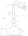
- FIG. 1 is a schematic diagram showing an overall configuration of a surgical operation system according to an embodiment of the present invention.
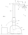
- FIG. 2 is a side view showing the overall configuration of the positioner.
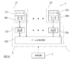
- FIG. 3 is a block diagram showing a schematic configuration of a positioner control system.
- FIG. 4 is a side view showing the overall configuration of the positioner in which the swing arm is tilted from the vertical.
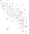
- FIG. 5 is a side view showing the overall configuration of the positioner with the platform tilted from the horizontal.
- FIG. 6 is a side view showing the overall configuration of the positioner when a columnar member is provided instead of the lifting shaft.
- FIG. 7 is a schematic diagram showing an overall configuration of a patient side manipulator arm.
- FIG. 1 is a schematic diagram showing an overall configuration of a surgical operation system according to an embodiment of the present invention.
- FIG. 2 is a side view showing the overall configuration of the positioner.
- FIG. 3 is a block diagram showing a schematic configuration of a positioner control system.
- FIG. 8 is a block diagram showing a schematic configuration of a control system of the arm body.
- FIG. 9 is a partial cross-sectional view of the arm body showing the layout of the drive system of the arm body.
- FIG. 10 is a plan view showing a connection structure between the platform and the patient side manipulator arm.
- 11 is a cross-sectional view taken along the line XI-XI in FIG.
- FIG. 12 is a block diagram illustrating a configuration for managing a patient-side manipulator arm attached to the platform.
- FIG. 13 is a plan view showing a connection structure between the platform and the patient side manipulator arm when the servo motor is provided on the platform.
- FIG. 14 is a partial cutaway view showing a configuration example of the distal end portion of the arm main body and the translation arm of the surgical operation system of FIG. 1.
- FIG. 15 is a diagram illustrating an operation example of the translation arm.
- FIG. 16 is a diagram illustrating a configuration example of the swing mechanism.
- FIG. 17 is a diagram illustrating an operation example of the swing mechanism.
- FIG. 18 is a diagram showing a first modification of the translation arm.
- FIG. 19 is a diagram showing a second modification example of the translation arm.
- FIG. 20 is a diagram illustrating a first modification of the swing mechanism.
- FIG. 21 is a diagram illustrating a second modification of the swing mechanism.
- FIG. 22 is a diagram illustrating a first modification example of the arm including the swinging mechanism.
- FIG. 23 is a diagram illustrating a second modification example of the arm including the swinging mechanism.
- a surgical operation system includes a platform, a plurality of manipulator arms connected to the platform, an instrument attached to a distal end portion of each of the plurality of manipulator arms, and the platform horizontally. And a positioner that supports the posture changeable from the posture.
- the positioner may include a horizontal articulated manipulator arm having a wrist connected to the platform.
- the positioner includes a base installed on a floor of an operating room, a column connected to a base end of the manipulator arm, and a base end of the column relative to the base. And a swinging arm that is connected so as to be swingable.
- the positioner may be connected to a first joint that connects the base end of the swing arm to the base so as to be rotatable about a horizontal rotation axis, and a distal end of the swing arm. And a second joint that pivotally connects the base end of the column portion about a horizontal rotation axis, and the vertical posture of the column portion by interlocking the first joint and the second joint. Further, a positioner control device that controls the operation of the first joint and the second joint may be further provided so that the above-mentioned is maintained.
- the surgical operation system will be described in detail with reference to the drawings.
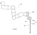
- FIG. 1 is a schematic diagram showing an overall configuration of a surgical operation system 100 according to an embodiment of the present invention.
- a surgical operation system 100 is a system in which an operator O such as a doctor performs endoscopic surgery on a patient P using a patient-side system 1 such as robot-assisted surgery or robot remote surgery. It is.
- the surgical operation system 100 includes a patient side system 1 and an operation device 2 for operating the patient side system 1.
- the operating device 2 is arranged away from the patient side system 1, and the patient side system 1 is remotely operated by the operating device 2.
- the operator O inputs an operation to be performed by the patient side system 1 to the operation device 2, and the operation device 2 transmits the operation command to the patient side system 1.
- the patient side system 1 receives the operation command transmitted from the operation device 2, and based on this operation command, the endoscope assembly 41, the instrument 42 (surgical instrument) and the like included in the patient side system 1 are provided. Make it work.
- each component of the surgical operation system 100 will be described in detail.
- the operation device 2 constitutes an interface between the surgical operation system 100 and the operator O, and is a device for operating the patient side system 1.
- the operating device 2 is installed beside the operating table 111, away from the operating table 111, or outside the operating room in the operating room.
- the operation device 2 includes an operation input unit 50 such as an operation manipulator arm 51 and an operation pedal 52 for the operator O to input an operation command, and a monitor 53 that displays an image photographed by the endoscope assembly 41. Including.
- the operator O operates the operation input unit 50 and inputs an operation command to the operation device 2 while visually checking the affected part on the monitor 53.
- the operation command input to the controller device 2 is transmitted to a controller 6 (described later) of the patient side system 1 by wire or wirelessly.
- the patient side system 1 constitutes an interface between the surgical operation system 100 and the patient P.
- the patient side system 1 is arranged beside the operating table 111 on which the patient P lies in the operating room. Inside the operating room is a sterile field.
- the patient-side system 1 includes a positioner 7, a platform 5 attached to the tip of the positioner 7, a plurality of patient-side manipulator arms (hereinafter simply referred to as “arm 3”) removably attached to the platform 5, An endoscope assembly 41 attached to the tip of one arm 3A of the plurality of arms 3, and an instrument 42 detachably attached to the tip of the other arm 3B of the plurality of arms 3.
- the sterilization drape 9 that shields the positioner 7 and the platform 5 from the sterilization field, and the controller 6 that controls the operation of the patient side system 1 are provided.
- the arm 3 to which the endoscope assembly 41 is attached may be referred to as “camera arm 3A”, and the arm 3 to which the instrument 42 is attached may be referred to as “instrument arm 3B”.
- the patient-side system 1 according to the present embodiment includes four arms 3 in combination of one camera arm 3A and three instrument arms 3B.
- the platform 5 has a function as a “hub” serving as a base for the plurality of arms 3.
- the positioner 7 and the platform 5 constitute a manipulator arm support S that supports the plurality of arms 3 in a movable manner.
- the manipulator arm support S only needs to include at least the platform 5.
- the manipulator is supported by the platform 5 supported by a linear motion rail, a lifting device, or a bracket attached to a ceiling or a wall.
- An arm support S may be configured.
- proximal end portion an end portion on the side toward the positioner 7 (more specifically, a contact portion with the floor of the operating room of the positioner 7) is referred to as a “proximal end portion”, and the opposite end thereof The end is referred to as the “tip”. Further, the proximal end portion may be referred to as “proximal end portion”, and the distal end portion may be referred to as “distal end portion”.
- the instrument 42 includes a drive unit 45 provided at a proximal end portion thereof, an end effector 44 (treatment instrument) provided at a distal end portion thereof, and an elongated shaft 43 connecting between the drive unit 45 and the end effector 44. (Both are shown in FIG. 7).
- a reference direction D is defined for the instrument 42, and the drive unit 45, the shaft 43, and the end effector 44 are arranged in parallel with the reference direction D.
- the end effector 44 of the instrument 42 is an instrument having an operating joint (for example, forceps, scissors, glass spar, needle holder, microdisector, staple applier, tucker, suction cleaning tool, snare wire, clip applier, etc. ) Or an instrument having no joint (for example, a cutting blade, an ablation probe, a washer, a catheter, a suction orifice, etc.).
- the controller 6 that receives the operation command from the operation device 2 first operates the positioner 7 so that the platform 5 and the operating table 111 or the patient P are in a predetermined positional relationship.
- the platform 5 is positioned.
- the controller 6 operates each arm 3 so that the sleeve (cannula sleeve) 110 placed on the body surface of the patient P, the endoscope assembly 41, and each instrument 42 are in a predetermined initial positional relationship.
- the endoscope assembly 41 and each instrument 42 are positioned.
- the positioning operation of the positioner 7 and each arm 3 may be performed simultaneously.
- the controller 6 moves each arm 3 in accordance with an operation command from the operating device 2 while the positioner 7 is stationary, and appropriately displaces and moves the endoscope assembly 41 and each instrument 42. While changing the posture, each instrument 42 is operated to perform the treatment.
- FIG. 2 is a side view showing the overall configuration of the positioner 7.
- the positioner 7 is based on a horizontal articulated robot, and includes a base 70 placed on the floor of the operating room, a lifting shaft 72, and base ends of the base 70 and the lifting shaft 72. And a horizontal arm 73 connected to the tip of the lifting shaft 72.
- the platform 5 is connected to the tip of the horizontal arm 73.
- the base 70 is, for example, a carriage with a brake, and can be moved to a desired position and stopped there.
- the base end of the swing arm 71 is connected to the base 70 via a rotary joint J71.
- the rotary joint J71 By the operation of the rotary joint J71, the swing arm 71 rotates (swings) about a horizontal rotation axis (swing axis) defined in the base 70.
- the distal end portion of the swing arm 71 is connected to the proximal end portion of the elevating shaft 72 via the rotary joint J72.
- the rotary joint J72 By the operation of the rotary joint J72, the swing arm 71 rotates (swings) about the horizontal rotation axis defined at the base end portion of the lifting shaft 72.
- the elevating shaft 72 extends vertically and can be expanded and contracted in the vertical direction.
- the elevating shaft 72 of this embodiment includes a cylindrical member 72a, a hollow shaft member 72b inserted into the cylindrical member 72a so as to be able to advance and retract in the vertical direction, and a translational joint J73 that connects the cylindrical member 72a and the shaft member 72b. Including. By the operation of the translation joint J73, the shaft member 72b moves forward and backward in the vertical direction with respect to the cylindrical member 72a.
- the horizontal arm 73 includes a first link 74 and a second link 75 that extend horizontally, and a wrist link 76 that is connected to the tip of the second link 75.
- the platform 5 is connected to the tip of the wrist link 76.
- the proximal end portion of the first link 74 is connected to the distal end portion of the elevating shaft 72 via the rotary joint J74.
- the first link 74 and the elevating shaft 72 form a right angle.
- the rotary joint J74 By the operation of the rotary joint J74, the first link 74 rotates around a vertical rotation axis defined at the tip of the lifting shaft 72.
- the distal end portion of the first link 74 is connected to the proximal end portion of the second link 75 via the rotary joint J75.
- the second link 75 rotates about a vertical rotation axis defined at the tip of the first link 74.
- the distal end portion of the second link 75 is connected to the proximal end portion of the wrist link 76 through the rotary joint J76.
- the wrist link 76 rotates around a horizontal rotation axis defined at the tip of the second link 75.
- the regular wrist link 76 extends vertically, and the platform 5 connected to the tip of the wrist link 76 is in a horizontal posture.
- FIG. 3 is a block diagram showing a schematic configuration of the control system of the positioner 7.
- the positioner 7 includes servomotors M71 to M76 for driving and encoders E71 to E76 for detecting the rotation angles of the servomotors M71 to M76 corresponding to the joints J71 to J76. Yes.
- the drive system of the rotary joint J71 and the rotary joint J76 is representatively shown, and the drive systems of the other joints J73 to J75 are omitted.
- the controller 6 includes a positioner control unit 601 that controls the operation of the positioner 7.
- Servo controllers C71 to C76 are electrically connected to the positioner controller 601.
- Servo motors M71 to M76 are electrically connected to the servo controllers C71 to C76 via an amplifier circuit (not shown).
- the position / orientation command of the platform 5 is input to the positioner control unit 601 based on the operation command input to the controller device 2.
- the positioner control unit 601 generates and outputs a position command value based on the position and orientation command and the rotation angles detected by the encoders E71 to E76.
- the servo controllers C71 to C76 that have acquired the position command value generate and output a drive command value (torque command value) based on the rotation angle and the position command value detected by the encoders E71 to E76.
- the amplifier circuit that has acquired the drive command value supplies a drive current corresponding to the drive command value to the servo motors M71 to M76. In this way, the servomotors M71 to M76 are servo-controlled so that the platform 5 reaches the position and orientation corresponding to the position and orientation command.
- the positioner 7 can change the mode according to the position and orientation command of the platform 5.
- the basic posture of the positioner 7 is that the swing arm 71 and the lifting shaft 72 extend vertically, the horizontal arm 73 extends horizontally, and is connected to the wrist link 76.
- the platform 5 is in a horizontal state.
- the positioner control unit 601 operates the rotary joint J71 to tilt the swing arm 71 from the vertical and operates the rotary joint J72.
- the vertical posture of the elevating shaft 72 is maintained. In this way, regardless of the inclination of the swing arm 71 from the vertical, the vertical of the lifting shaft 72 and the horizontal of the horizontal arm 73 are maintained.
- the positioner 7 When the swing arm 71 is tilted from the vertical as described above, the positioner 7 has a C-shape as a whole. As a result, the positioner 7 is configured such that the base 70 is positioned below the operating table 111, the lifting shaft 72 is positioned beside the operating table 111, and the horizontal arm 73 is positioned above the operating table 111. be able to. In this way, by storing the base 70 below the operating table 111, it is possible to secure the flow line of the assistant who assists the operation around the operating table 111 during the operation.
- the platform 5 is tilted from the horizontal.
- the basic axis (swivel axis) Lp of the arm 3 attached to the platform 5 is simultaneously inclined from the vertical.
- the angle range of the reference direction D defined for the instrument 42 is expanded, and the instrument 42 can be inserted into the patient P with a greater inclination from the vertical. In this manner, the insertion direction of the instrument 42 with respect to the patient P can be adjusted appropriately according to the patient's P position and surgical position.
- the configuration of the positioner 7 can be changed as follows, for example.
- the elevating shaft 72 expands and contracts in the vertical direction, but a columnar member 72 ′ that does not expand and contract may be used instead of the elevating shaft 72 as shown in FIG.
- the translation joint J73 is omitted.
- the height position of the platform 5 is adjusted mainly by expansion and contraction of the lifting shaft 72.
- the height of the platform 5 is mainly adjusted by the inclination of the swing arm 71 from the vertical. Adjust the position.
- FIG. 7 shows a schematic configuration of one of the plurality of arms 3 included in the patient-side system 1.
- the arm 3 includes an arm body 30 and a translation arm 35 connected to the distal end portion of the arm body 30, and the distal end portion can be moved in a three-dimensional space with respect to the proximal end portion. It is configured to be able to.
- the plurality of arms 3 included in the patient-side system 1 have the same or similar configuration, but at least one of the plurality of arms 3 may have a different configuration. .
- a holder (instrument holding unit) 36 that holds the instrument 42 is provided at the tip of the translation arm 35.
- An instrument 42 is detachably held by the holder 36.
- the shaft 43 of the instrument 42 held by the holder 36 extends parallel to the reference direction D.
- a holder 36 is provided at the distal end of the translation arm 35 as in the case of the instrument arm 3B, and the endoscope assembly 41 is detachably held by the holder 36. Is done.
- the aspect of the holder 36 provided on the camera arm 3A may be different from that of the holder 36 provided on the instrument arm 3B.
- the endoscope assembly 41 may be fixed to the camera arm 3A.
- the arm 3 is detachable from the platform 5 (that is, easy to attach and remove), and has water resistance, heat resistance, and chemical resistance for cleaning treatment and sterilization treatment.
- a high-pressure steam sterilization method for example, an EOG sterilization method, a chemical sterilization method using a disinfectant, or the like may be selectively used.
- the arm 3 is sealed in a high-pressure vessel such as an autoclave and exposed to saturated steam at a predetermined pressure for a predetermined time (for example, 115 ° C. for 30 minutes, 121 ° C. for 20 minutes, or 126 ° C. for 15 minutes). .
- the arm 3 is sealed in a container, and 450 to 1000 mg / L of ethylene oxide gas is circulated through the container.
- the arm 3 is immersed in a disinfectant such as glutaral.
- the arm body 30 includes a base 80 that is detachably attached to the platform 5, and first to sixth links 81 to 86 that are sequentially connected from the base 80 toward the distal end portion. More specifically, the proximal end portion of the first link 81 is connected to the distal end portion of the base 80 via a torsional joint J31. The proximal end portion of the second link 82 is connected to the distal end portion of the first link 81 via a torsional joint J32. The proximal end portion of the third link 83 is connected to the distal end portion of the second link 82 via a bending joint J33.
- a proximal end portion of the fourth link 84 is connected to a distal end portion of the third link 83 via a torsion joint J34.
- the proximal end portion of the fifth link 85 is connected to the distal end portion of the fourth link 84 via the bending joint J35.
- the proximal end portion of the sixth link 86 is connected to the distal end portion of the fifth link 85 via a torsional joint J36.
- the proximal end portion of the translation arm 35 is connected to the distal end portion of the sixth link 86.
- the outer shell of the arm body 30 is mainly formed of a member having heat resistance and chemical resistance such as stainless steel.
- sticker (not shown) for providing water resistance is provided in the connection part of links.
- This seal has heat resistance corresponding to the high-pressure steam sterilization method and chemical resistance against disinfectants.
- the edge part of the other link is inserted inside the edge part of one link to be connected, and a seal is arranged so as to fill the space between the edge parts of these links. As a result, the seal is hidden from view. Thereby, infiltration of water, a chemical
- FIG. 8 is a block diagram illustrating a schematic configuration of a control system of the arm body 30, and FIG. 9 is a schematic cross-sectional view of the arm body 30 illustrating a layout of a drive system of the arm body 30.
- the arm body 30 having the above-described configuration includes drive servomotors M31 to M36, encoders E31 to E36 for detecting rotation angles of the servomotors M31 to M36, and servomotors M31 to M36 corresponding to the joints J31 to J36.
- Reducers R31 to R36 are provided that decelerate the output of M36 to increase the torque.
- FIG. 8 the control system of the torsional joint J31 and the torsional joint J36 among the joints J31 to J36 is representatively shown, and the control system of the remaining joints J33 to J35 is omitted.
- the encoders E31 to E36 are provided as an example of rotational position detecting means for detecting the rotational positions (rotational angles) of the servo motors M31 to M3. Instead of the encoders E31 to E36, rotational position detecting means such as a resolver is provided. May be used.
- rotational position detecting means such as a resolver is provided. May be used.
- each of the above-described elements of the drive system of the arm body 30 and the wiring and control unit for these elements are made of a high-temperature resistant material and have heat resistance for sterilization.
- a servo motor M31 is provided at the base end of the first link 81, and a speed reducer R31 is provided at the tip of the base 80.
- the speed reducer R31 according to the present embodiment is of a unit type including a gear that reduces the rotational speed of input power and an output gear that receives the output.
- the servo motor M31 is arranged so that its output shaft is parallel to the rotation shaft of the torsional joint J31.
- the encoder E31 is attached to the servo motor M31.
- the output of the servo motor M31 is input to the reduction gear R31. Since the output gear of the reduction gear R31 is fixed to the first link 81, the first link 81 rotates with respect to the base 80 by the output from the reduction gear R31.
- a servo motor M32 is provided at the distal end portion of the first link 81, and a speed reducer R32 is provided at the proximal end portion of the second link 82. ing.
- the servo motor M32 is arranged so that its output shaft is parallel to the rotation shaft of the torsional joint J32.
- the encoder E32 is attached to the servo motor M32.
- a speed reducer R33 is provided at the distal end portion of the second link 82
- a servo motor M33 is provided at the proximal end portion of the third link 83. ing.
- the servo motor M33 is arranged so that its output shaft is parallel to the rotation shaft of the bending joint J33.
- the encoder E33 is attached to the servo motor M33.
- servo motors M34 to M36, encoders E34 to E36, and reduction gears R34 to R36 are also arranged in the remaining joints J34 to J36.
- Servo motors M31 to M36 have a small output (for example, about 80 W), are light and small.
- the reduction gears R31 to R36 have a flat shape with a small dimension in the axial direction and can obtain a high torque with a high reduction ratio (for example, 100 or more).
- the arm 3 of the patient-side system 1 does not require a high-speed servomotor because it does not require high-speed operation like a general industrial manipulator. Therefore, by using a combination of servo motors M31 to M36 with relatively small outputs and reducers R31 to R36 having a relatively high reduction ratio, the arm 3 can be reduced in weight and size while ensuring the necessary torque. ing.
- the output of the servo motor is transmitted in the order of the output gear, the speed reducer, and the load.
- the output of the servo motor is the speed reducer, the output gear, and the load. It is transmitted in order.
- the weight reduction and size reduction of the arm 3 are also realized by laying down the reduction gear on the input side with respect to the output gear.
- the controller 6 includes an arm main body control unit 602 that controls the operation of the arm main body 30.
- Servo controllers C31 to C36 are electrically connected to the arm main body controller 602, and servomotors M31 to M36 are electrically connected to the servo controller 79 via an amplifier circuit (not shown).
- the position / orientation command of the distal end portion of the arm main body 30 is input to the arm main body control unit 602.
- the arm body controller 602 generates and outputs a position command value based on the position and orientation command and the rotation angles detected by the encoders E31 to E36.
- the servo control units C31 to C36 that have acquired the position command value generate and output drive command values (torque command values) based on the rotation angles and position command values detected by the encoders E31 to E36.
- the amplifier circuit that has acquired the drive command value supplies a drive current corresponding to the drive command value to the servo motors M31 to M36. In this way, the servomotors M31 to M36 are servo-controlled so that the tip of the arm body 30 reaches the position and posture corresponding to the position and orientation command.
- the base 80 of the arm 3 is detachable from the platform 5. In other words, it is easy to remove and attach the entire arm 3 from the patient-side system 1.
- the four arms 3 can be attached to and detached from the platform 5, but at least one of the arms 3 included in the patient-side system 1 may be attached to and detached from the platform 5.
- the arm 3 removed from the patient-side system 1 is reused within a limited number of times after being subjected to a cleaning process and a sterilization process. In this way, the arm 3 can be replaced with a clean one that is sterilized at each operation. Therefore, the arm 3 may not be covered with a sterilized drape as in the prior art, but may be exposed to a sterilized field.
- FIG. 10 is a plan view showing a connecting structure between the platform 5 and the arm 3, and FIG. 11 is a cross-sectional view taken along the line XI-XI in FIG.
- the base end portion of the base 80 of the arm 3 has a cylindrical shape, and at least one interface portion (hereinafter referred to as “I / F portion 801”) is provided around the base end surface.
- the I / F portion 801 according to the present embodiment is a protrusion formed on the outer peripheral surface of the base 80, but the aspect of the I / F portion 801 is not limited to this.
- an IC tag 91 for attaching identification information or the like to the arm 3 is embedded.
- the IC tag 91 includes an IC chip and an antenna, and the IC chip includes a microcomputer, an EEPROM, a RAM, and the like (all not shown).
- the IC tag 91 stores individual identification information, model number, number of uses, etc. of the arm 3.
- the I / F unit 801 is provided with one or more connectors 92.
- the one or more connectors 92 include a connector of an electric wire that supplies electricity to the arm 3, a connector of communication wiring that transmits and receives signals to and from the arm 3, and the like.
- the platform 5 is provided with a mounting port 55 to which the I / F unit 801 of the base 80 is connected.
- the attachment port 55 (an example of a manipulator arm attachment portion) according to the present embodiment is a recess into which the protruding I / F portion 801 can be fitted, but the aspect of the attachment port 55 is not limited to this.
- the platform 5 since the four arms 3 are detachably attached to the platform 5, at least four attachment ports 55 are provided on the platform 5.
- the platform 5 has a hexagonal shape in which two adjacent corners of a quadrangle are chamfered in a plan view, and three consecutive side surfaces thereof have components directed in the same direction.
- One mounting port 55 is provided on each of the three side surfaces.
- a side wall 59 is formed by partially cutting off the lower part of the platform 5, and the lower three mounting ports 55 are formed on the wall 59 as well as the three upper mounting ports 55.
- a port 55 is provided. In this embodiment, one of the three lower mounting ports 55 is used, and the other two are vacant.
- the platform 5 is provided with a plurality of attachment ports 55, and the attachment ports 55 to be used for each operation can be selected.
- the I / F portion 801 provided on the base 80 of the arm 3 and the mounting port 55 provided on the platform 5 constitute a coupling mechanism for connecting the arm 3 and the platform 5. Then, the base 80 (ie, the arm 3) is attached to the platform 5 by fitting the I / F portion 801 of the base 80 into the attachment port 55 of the platform 5.
- a socket 56 is provided at a position corresponding to the connector 92 provided in the I / F unit 801. As the I / F unit 801 and the attachment port 55 are coupled, the connector 92 and the socket 56 are automatically connected. An electric wire and / or communication wiring is connected to the socket 56 through an internal space of hollow elements (shafts, links, etc.) constituting the platform 5 and the positioner 7.
- the connector 92 is exposed on the surface of the arm 3 and can contact the socket 56. However, the connector 92 is embedded near the surface of the arm 3 so that the socket 56 and the connector 92 are not in contact with each other by electromagnetic induction or the like. An electrically connected configuration may be employed. Further, the socket 56 may be provided in the I / F unit 801, and the connector 92 may be provided in the attachment port 55.
- the platform 5 is provided with a reader / writer 93 that reads and writes (stores) information of the IC tag 91 embedded in the arm 3.
- the reader / writer 93 is provided corresponding to each mounting port 55 of the platform 5 and outputs information read from the IC tag 91 to the controller 6 described later.
- the reader / writer 93 may individually read the IC tags 91 of the arms 3 attached to the platform 5 or read the IC tags 91 of all the arms 3 attached to the platform 5 at a time. It may be.
- the platform 5 and the base 80 have at least one set capable of mounting lock (holding) and unlocking (holding release) of the arm 3 attached to the platform 5 so that the base 80 does not fall off from the platform 5.
- a mounting lock mechanism 94 is provided.
- the mounting lock means that the I / F portion 801 of the arm 3 attached to the mounting port 55 of the platform 5 is fixed to the mounting port 55, and the unlocking means that the fixing is released.
- the mounting lock mechanism 94 includes a support side engaging portion 94a provided at or near the mounting port 55 of the platform 5, and an arm side engaging portion 94b provided at or near the I / F portion 801 of the arm 3. It is configured by collaboration. One of the support side engaging portion 94a and the arm side engaging portion 94b is engaged with the other, and the other is engaged with one.
- the I / F part 801 is locked in a state of being attached to the attachment port 55 by the engagement of the support side engaging part 94a and the arm side engaging part 94b, and the support side engaging part 94a The lock is released so that the I / F part 801 can be detached from the attachment port 55 by releasing the engagement of the arm side engaging part 94b.
- the mounting lock mechanism 94 as described above is provided, for example, with a protrusion provided on one of the platform 5 and the base 80, a lever with a latch provided on the other, a recess provided on one of the two, and the other.
- the engagement claw is selected from the group consisting of a recess provided in one of the engaging claws and a ball plunger provided in the other.
- the attachment lock mechanism 94 may be another known attachment lock mechanism.
- the mounting lock mechanism 94 is a mechanism that does not use tools such as bolts and nuts for locking / unlocking the mounting, and that can be locked / unlocked by one-touch operation.
- FIG. 12 is a block diagram showing a configuration for managing the arm 3 attached to the platform 5.
- the controller 6 includes an arm management unit (management device) 603 for managing the arm 3 attached to the platform 5.
- a reader / writer 93 is electrically connected to the arm management unit 603.
- the arm management unit 603 detects that the connector 92 and the socket 56 are connected based on the power supply from the platform 5 to the arm 3. Power supply from the platform 5 to the arm 3 can be detected based on, for example, a detection signal from a current detection sensor (detection sensor 57) provided on an electric wire up to the socket 56 or communication wiring.
- the connection between the connector 92 and the socket 56 means that the I / F unit 801 is normally attached to the attachment port 55. That is, the presence / absence of the arm 3 attached to the attachment port 55 can be detected based on the presence / absence of power supply from the platform 5 to the arm 3. In this way, the arm management unit 603 can detect that the arm 3 is attached to each attachment port 55 provided in the platform 5.
- a contact-type or non-contact-type object detection sensor may be provided in the platform 5 in order to detect the presence or absence of the arm 3 attached to the attachment port 55.
- the arm management unit 603 detects that the arm 3 is attached to the attachment port 55 based on the detection signal from the detection sensor.
- the arm management unit 603 When the arm management unit 603 detects that the arm 3 is attached to the attachment port 55, the arm management unit 603 causes the reader / writer 93 to perform a read operation, and the reader / writer 93 is connected to the platform 5 based on information read from the IC tag 91.
- the individual identification information, the model number information (type), the number-of-uses information, and the like of each arm 3 is acquired.
- the arm management unit 603 temporarily stores the acquired information in association with the mounting position information (that is, the mounting port 55) on the platform 5 to which the arm 3 is mounted.
- Each of the plurality of attachment ports 55 is identified.
- the operation information is input and set (stored) in advance in the controller 6 via the operation device 2.
- This operation information includes a combination of a plurality of arms 3 used in the operation.
- the arm management unit 603 determines whether the combination of the individual identification information included in the information acquired from the reader / writer 93 corresponds to the combination set as the surgery information. If the combination does not correspond to the combination set as the operation information, the arm management unit 603 outputs a warning through the warning device 605 connected to the controller 6.
- the warning device 605 warns the surgeon O by one or more of light, sound, and image. In this way, the arm management unit 603 manages the arm 3 attached to the platform 5 so that the appropriate arm 3 can be attached.
- the surgery information may include information relating to a combination of individual identification information of the arm 3 used in the surgery and an attachment position (that is, the attachment port 55) of the platform 5 to which the arm 3 is to be attached. .
- the arm management unit 603 has a combination of the individual identification information included in the information acquired from the reader / writer 93 and the mounting position information (that is, the mounting port 55) on the platform 5 stored in association therewith. It is determined whether or not it corresponds to the information set as the surgery information. If the combination does not correspond to the combination set as the operation information, the arm management unit 603 outputs a warning through the warning device 605 connected to the controller 6. In this manner, the arm management unit 603 allows the arm attached to the platform 5 so that the arm 3 is attached to an appropriate position on the platform 5 and the appropriate arm 3 is attached to each attachment port 55. 3 is managed.
- the surgical information includes information on the combination of the model number information of the arm 3 used in the surgery and the mounting position on the platform 5 to which the arm 3 is to be mounted (that is, the mounting port 55). Also good.
- the arm management unit 603 corresponds to the combination of the model number information included in the information acquired from the reader / writer 93 and the attachment position (attachment port 55) associated therewith set as the operation information. If the combination does not correspond to that set as the operation information, a warning may be output through a warning device 605 connected to the controller 6.
- the type of arm 3 varies depending on the model number (camera arm 3A, instrument arm 3B) and structure (link length, degree of freedom, etc.).
- the model number information is stored in the IC tag 91, but the storage device 604 includes a model number storage unit in which the model number information is stored in association with the individual identification information, and the arm management unit 603 determines the model number based on the individual identification information.
- the corresponding model number information may be read from the storage unit, and this model number information may be used instead of the model number information read from the IC tag 91 in the above processing.
- the storage device 604 of the controller 6 includes a use limit number storage unit in which the use limit number associated with the individual identification information is stored. Based on the individual identification information acquired from the IC tag 91, the arm management unit 603 reads the use limit count corresponding to this from the storage device 604, and compares the use limit count with the acquired use count information. The arm management unit 603 outputs a warning through the warning device 605 connected to the controller 6 if the usage count information exceeds the usage limit count. In this way, the arm management unit 603 manages the number of times the arm is used so that the arm 3 is not used beyond the usage limit number. The arm 3 is a consumable item, and the arm 3 that has been used for a limited number of times is discarded.
- the arm management unit 603 operates the reader / writer 93 so that new usage count information obtained by adding 1 to the usage count information acquired from the IC tag 91 is written in the IC tag 91.
- the IC tag 91 of the arm 3 holds information related to the number of times it is used. Therefore, the arm 3 can be shared with other patient-side systems 1.
- the arm 3 itself holds the usage count information of the arm 3, but the usage count information of the arm 3 may be stored in the storage device 604 of the controller 6.
- the arm management unit 603 may read the corresponding usage count information from the storage device 604 based on the individual identification information read from the IC tag 91 by the reader and use it for the above processing.
- connection structure between the platform 5 and the arm 3 has been described above.
- connection structure between the platform 5 and the arm 3 can be changed as follows, for example.
- the platform 5 is provided with six attachment ports 55, and the arm 3 is connected to four of these attachment ports 55.
- the platform 5 may be provided with five or more attachment ports 55, and the attachment ports 55 at appropriate positions corresponding to the contents of the operation may be selectively used.
- the IC tag 91 is provided on the arm 3 so that the arm 3 itself holds information.
- the IC tag 91 is an example of information holding means provided in the arm 3, and other information holding means may be used instead of or in addition to the IC tag 91.
- a bar code may be provided on the arm 3 and a bar code reader may be provided on the platform 5.
- a shape symbol such as an unevenness may be provided on the arm 3 and a reader for reading the shape symbol may be provided on the platform 5.
- the connector 92 is provided in the I / F portion 801 of the base 80 of the arm 3 and the socket 56 is provided in the mounting port 55 of the platform 5, but the connector 92 and the socket 56 are omitted. Also good.
- the arm 3 is connected to a wire other than the I / F unit 801 for supplying power and / or wiring for communication.
- the drive system of the arm 3 (particularly, the arm main body 30) is mounted on itself, but a part of the drive system of the arm main body 30 may be provided on the platform 5.
- a servo motor M31 that drives the torsional joint J31 may be provided in the platform 5.
- a servo motor M31 is built in the platform 5, and a female coupler-shaped mounting port 55 is provided around the output shaft 96 of the servo motor M31.
- the output portion of the reduction gear R31 is fixed to the proximal end portion of the first link 81 of the arm 3, and the proximal end portion of the base 80 is a male coupler-shaped I / F portion 801 corresponding to the mounting port 55.
- An input shaft 95 for inputting power to the reduction gear R31 is provided in the base 80.
- the input shaft 95 is an input shaft that transmits power to the power system of the arm 3.
- a shaft coupling 97 such as an Oldham coupling is provided between the output shaft 96 of the servo motor M31 and the input shaft 95 to the reduction gear R31.
- the translation arm 35 translates the holder 36 attached to the tip of the translation arm 35 in the reference direction D, thereby causing the instrument 42 attached to the holder 36 to extend the shaft 43. It is a mechanism that translates in the current direction.
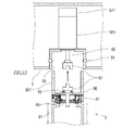
- FIG. 14 is a partial cutaway view showing a configuration example of the distal end portion of the arm body 30 and the translation arm 35.
- the translation arm 35 includes a base end side link 61, a front end side link 62, a first connection shaft 63 and a second connection that connect the base end side link 61 and the front end side link 62. It has a shaft 66 and an interlocking mechanism 64.
- a rotation shaft 68 is provided at the distal end of the translation arm 35, that is, at the distal end of the distal end side link 62.
- the drive source of the translation arm 35 is provided on the link at the tip of the arm body 30, that is, the sixth link 86.
- a translation arm rotation drive unit 48 that rotates the second translation arm drive shaft 38 is provided.
- the first translation arm drive shaft 37 and the second translation arm drive shaft 38 are attached to the distal end portion of the arm main body 30 so that the base end portion can rotate about the first axis L1 perpendicular to the reference direction D.
- the second translational arm drive shaft 38 is held by the arm body 30 via a seal bearing 30 b having a seal whose base end blocks the inside and outside environment of the arm body 30.
- the second translation arm drive shaft 38 is formed in a hollow cylindrical shape, and the first translation arm drive shaft 37 is nested inside the second translation arm drive shaft 38. Therefore, the first translation arm drive shaft 37 and the second translation arm drive shaft 38 are configured to rotate around the same axis.
- the first axis L1 is configured to extend in the tangential direction of a circle centered on the turning axis Lp (see FIG. 7) of the arm body 30. That is, the first axis L1 extends in the depth direction in FIG.
- the first translation arm drive shaft 37 and the second translation arm drive shaft 38 protrude from the distal end portion of the arm body 30 and are connected to the proximal end side link 61 of the translation arm 35. That is, the arm body 30 and the translation arm 35 are connected via the first translation arm drive shaft 37 and the second translation arm drive shaft 38.
- the first translation arm drive shaft 37 is a drive shaft that operates the translation arm 35 by differential with the second translation arm drive shaft 38, and the second translation arm drive shaft 38 is connected to the first translation arm drive shaft 37.
- This is a drive shaft that rotates the translation arm 35 around the first axis L1 by differential.
- the first translation arm drive shaft 37 and the second translation arm drive shaft 38 are configured to be independently rotated by separate drive units.
- the first translation arm drive shaft 37 is connected to the output shaft 47 a of the translation arm drive unit 47 and rotates by the rotation of the output shaft 47 a of the translation arm drive unit 47.
- the second translation arm drive shaft 38 is connected to the output shaft 48 a of the translation arm rotation drive unit 48 and rotates by the rotation of the output shaft 48 a of the translation arm rotation drive unit 48.
- These drive units are, for example, servo motors. Therefore, the angular positions of the first translation arm drive shaft 37 and the second translation arm drive shaft 38 around the first axis L1 can be controlled independently of each other.
- the proximal end link 61 is connected to the distal end portion 30a of the arm body 30 so that the proximal end link 61 is rotatable about the first axis L1.
- “continuous” means not only the case where two things are directly connected, but also the case where other things are interposed between the two things and include cases where they are indirectly connected. To do.
- the proximal end side link 61 is advanced so that the distal end portion of the proximal end side link 61 is positioned on the side away from the first axis L1 in the reference direction D with respect to the retraction angle position P1 (see FIG. 15) and the retraction angle position P1. It is configured to rotate within a range including the angular position P2 (see FIG. 15).
- the proximal end side link 61 is hollow. And the front-end
- the first translation arm drive shaft 37 is rotated by the rotation of the output shaft 47a of the translation arm drive unit 47, and the proximal side link 61 is rotated about the first axis L1 by the rotation of the first translation arm drive shaft 37. It is configured to move.
- the proximal end side link 61 is attached to the distal end portion 30 a of the arm main body 30.
- the distal end side link 62 is connected to the distal end portion of the proximal end side link 61 so that the distal end side link 62 can rotate around the second axis L2 extending in parallel with the axis L1.
- the distal end side link 62 rotates within a range including a contraction angle position P3 (see FIG. 15) and an expansion angle position P4 having a larger angle with the base end side link 61 than the contraction angle position P3. Configured to work.
- the base end side link 61 and the front end side link 62 are configured to take a posture refracted in an L shape.
- the distal end side link 62 is hollow.
- the first connecting shaft 63 has a proximal end portion fixed to the distal end portion of the proximal end side link 61, and the distal end portion is attached to the proximal end portion of the distal end side link 62 so as to be rotatable around the second axis L2.
- the second connecting shaft 66 is attached to the proximal side link 61 so as to be rotatable around the second axis L2 via a seal bearing 61b having a seal whose base end blocks the inner and outer spaces of the proximal side link 61.
- the distal end portion is fixed to the proximal end portion of the distal end side link 62.
- the second connecting shaft 66 is formed in a hollow cylindrical shape, and the first connecting shaft 63 is disposed in a nested manner inside the second connecting shaft 66. Therefore, the first connecting shaft 63 and the second connecting shaft 66 are configured to rotate around the same axis.
- the translation arm 35 is configured such that a virtual straight line L (see FIG. 15) connecting the base end portion of the base end side link 61 and the front end portion of the front end side link 62 faces the reference direction D.
- the proximal end portion of the distal end side link 62 is attached to the distal end portion of the proximal end side link 61.
- the rotation shaft 68 is attached to the distal end portion of the distal end side link 62 so that the proximal end portion can rotate around the third axis L3 extending in parallel with the first axis L1 and the second axis L2. It is fixed to the holder 36.
- the rotation shaft 68 is held at the distal end portion of the distal end side link 62 via a seal bearing 62 a having a seal that blocks the inner and outer spaces of the distal end side link 62.
- the translation arm 35 is located on the side from the proximal end portion of the shaft 43 of the instrument 42 held by the holder 36 in the reference direction D from the distal end portion 30a of the arm body 30 toward the distal end portion. It is arranged.
- the distance between the axis of the rotating shaft 68 (third axis L3) and the axis of the first connecting shaft 63 and the second connecting shaft 66 (second axis L2) is the first translation arm driving shaft 37 and second translation arm driving.
- the distance between the axis of the shaft 38 (second axis L2) and the axis of the first connecting shaft 63 and the second connecting shaft 66 (first axis L1) is the same.
- the interlock mechanism 64 interlocks the distal end side link 62 with the contraction angle position P3 (see FIG. 15) in conjunction with the turning operation from the retraction angle position P1 (see FIG. 15) toward the advance angle position P2 (see FIG. 15). 15) to the expansion angle position P4 (see FIG. 15), and from the advance angle position P2 (see FIG. 15) of the proximal side link 61 toward the retraction angle position P1 (see FIG. 15).
- This is a mechanism for rotating the front end side link 62 from the expansion angle position P4 (see FIG. 15) toward the contraction / closing angle position P3 (see FIG. 15) in conjunction with the rotation operation.
- the distal end side link 62 is configured to rotate when the driving force of the translation arm driving unit 47 is transmitted by the interlocking mechanism 64. Further, the interlocking mechanism 64 is configured to cause the distal end portion of the distal end side link 62 to move straight in the reference direction D.
- a mechanism using a timing belt will be exemplified as an example of the interlocking mechanism 64.
- the interlocking mechanism 64 includes two pairs of pulleys (a first pulley 65a and a second pulley 65b, a third pulley 65c and a fourth pulley 65d), and two pairs spanned between each pair of pulleys. And an annular timing belt (first belt 67a, second belt 67b).
- the first pulley 65 a is fixed to the distal end portion of the second translation arm drive shaft 38 and is located in the proximal end portion of the internal space of the proximal end link 61. Therefore, the first pulley 65a is configured to be rotatable around the first axis L1.
- the second pulley 65 b is paired with the first pulley 65 a, is fixed to the proximal end portion of the second connecting shaft 66, and is located at the distal end side portion of the internal space of the proximal end side link 61. Therefore, the second pulley 65b is configured to be rotatable around the second axis L2.
- a first belt 67a is bridged between the first pulley 65a and the second pulley 65b. Accordingly, the second pulley 65b is configured to rotate (spin) by revolving around the first pulley 65a.
- the pulley ratio which is the ratio between the diameter of the first pulley 65a and the diameter of the second pulley 65b, is 2: 1.
- the third pulley 65 c is fixed to the distal end portion of the first connecting shaft 63 and is located in the proximal end portion of the internal space of the distal end side link 62. Therefore, the third pulley 65c is configured to be rotatable around the second axis L2.
- the fourth pulley 65 d is paired with the third pulley 65 c, is fixed to the proximal end portion of the rotating shaft 68, and is positioned at the distal end side portion of the internal space of the distal end side link 62. Therefore, the fourth pulley 65d is configured to be rotatable around the third axis L3.
- a second belt 67b is stretched between the third pulley 65c and the fourth pulley 65d. Therefore, the fourth pulley 65d is configured to rotate (spin) by revolving around the third pulley 65c.
- the pulley ratio which is the ratio of the diameter of the third pulley 65c and the diameter of the fourth pulley 65d, is 1: 2.
- the translation arm 35 is driven by the controller 6 controlling the first translation arm drive shaft 37 and the second translation arm drive shaft 38 based on the operation command input to the controller device 2.
- FIG. 15 is a diagram illustrating an operation example of the translation arm 35.
- the proximal end side link 61 is retracted. It is rotated ⁇ degrees from the position P1 toward the advance angle position P2.
- the second pulley 65b revolves around the first axis L1. Since the first pulley 65a and the second pulley 65b are connected by the first belt 67a, the second pulley 65b rotates in a direction opposite to the rotation direction of the proximal end side link 61 with respect to the first pulley 65a. Then, the phases of the first pulley 65a and the second pulley 65b change.
- the angular displacement is -2 ⁇ degrees based on the pulley ratio.
- the second connecting shaft 66 to which the second pulley 65b is fixed rotates, and the distal end side link 62 fixed to the second connecting shaft 66 expands from the contraction angle position P3. It rotates by -2 ⁇ toward the open angle position P4. Accordingly, the distal end portion of the distal end side link 62 moves on a virtual straight line L connecting the proximal end portion of the proximal end side link 61 and the distal end portion of the distal end side link 62.
- this virtual straight line is comprised so that it may face in the reference direction D
- tip part of the front end side link 62 moves to the side away from the 1st axis line L1 in the reference direction D.
- the distal end portion of the distal end side link 62 moves straight in the reference direction D.
- the instrument 42 inserted into the sleeve 110 can be smoothly moved in the reference direction D.
- the first translation arm drive shaft 37 and the second translation arm drive shaft 38 are rotated in synchronization with each other, whereby the entire translation arm 35 can be turned around the first axis L1 with respect to the arm body 30. . Accordingly, the direction of the reference direction D can be changed, and the direction in which the distal end portion of the distal end side link 62 moves straight can be changed around the first axis L1. Further, without providing the second translation arm drive shaft 38 and the translation arm rotation drive unit 48, the first pulley 65a is fixed to the distal end portion 30a of the arm body 30, and the translation arm is moved by moving the distal end portion of the arm body 30. The entire 35 may be turned around the first axis L1.
- the fourth pulley 65d revolves around the second axis L2 by the rotation of the distal end side link 62.
- the angular position of the third pulley 65c fixed to the distal end portion of the proximal end side link 61 by the first connecting shaft 63 is not changed by the rotation of the distal end side link 62, and the third pulley 65c and the fourth pulley 65d are
- the fourth pulley 65d rotates with respect to the third pulley 65c in the direction opposite to the rotation direction of the distal end side link 62, and the third pulley 65c and the fourth pulley 65d are connected to each other by the second belt 67b.
- the phase changes.
- the angular displacement is ⁇ degrees based on the pulley ratio.
- the proximal link 61 is retracted from the advance angle position P2. It rotates toward the angular position P1, and the distal end side link 62 rotates from the expanded angle position P4 toward the contracted and closed angle position P3. Accordingly, the holder 36 moves toward the first axis L ⁇ b> 1 in the reference direction D while maintaining the posture with respect to the arm body 30.
- the translation arm 35 has a folded state in which the proximal end side link 61 is located at the retraction angle position P1 and the distal end side link 62 is located at the contraction angle position P3, and the proximal end side link 61 is an advance angle.
- the instrument 42 is moved in the reference direction D (advanced / retracted / reciprocated) by moving between the extended state where the distal end side link 62 is located at the expansion angle position P4 while being located at the position P2. Can do. Therefore, the dimensions of the arm 3 in the reference direction D can be made compact compared to the configuration in which the holder 36 is moved in the reference direction D by the linear motion joint.
- the translation arm 35 is connected to the arm body 30 and the holder 36 by a rotating joint, and the links constituting the translation arm 35, that is, the proximal end link 61 and the distal end side link 62 are also connected by a rotating joint. . Therefore, since the exposed part to the external space of the internal space of the arm can be reduced, it is possible to effectively suppress the dust, germs and the like generated in the internal space of the arm from scattering to the external space. Further, as described above, by using the seal bearing for the rotary joint, it is possible to prevent dust, germs, and the like generated in the internal space of the arm from scattering to the external space. Therefore, contamination of the operating room can be effectively prevented.
- the interlocking mechanism 64 is configured to rotate the distal end side link 62 in conjunction with the rotational operation of the proximal end side link 61, the drive unit that rotates only the distal end side link 62 can be omitted.
- the configuration of the translation arm 35 can be simplified.
- the mechanism using a timing belt was illustrated as an example of the interlocking mechanism 64, it is not limited to this mechanism, and instead of this, for example, a mechanism including a gear train may be used. A mechanism may be used. Moreover, you may comprise so that the base end side link 61 and the front end side link 62 may each rotate with the drive force of the drive part provided separately.
- FIG. 18 is a diagram showing a first modification of the translation arm.
- the translation arm 35 is located on the side from the proximal end portion of the shaft 43 of the instrument 42 held by the holder 36 in the reference direction D from the distal end portion 30a of the arm body 30 to the distal end portion.
- the present invention is not limited to this.
- the translation arm 335 is a side from the distal end portion 30a of the arm main body 30 toward the proximal end portion from the distal end portion of the shaft 43 of the instrument 42 held in the holder 36 in the reference direction D. It may be arranged so that it may be located in.
- FIG. 19 is a diagram showing a second modification example of the translation arm.
- the translation arm 35 illustrated the structure by which the base end part of the front end side link 62 was attached to the front end part of the base end side link 61, it is not restricted to this. It may replace with this and may be constituted as follows.
- the translation arm 435 is configured such that an intermediate link unit 460 having a first intermediate link 461 and a second intermediate link 462 is interposed between the proximal end side link 61 and the distal end side link 62.
- the translation arm 435 includes a first connection shaft 463a that connects the base end side link 61 and the first intermediate link 461, a second connection shaft 463b that connects the first intermediate link 461 and the second intermediate link 462, and It has the 3rd connecting shaft 463c which connects the 2nd intermediate link 462 and the front end side link 62.
- the interlocking mechanism of the translation arm 435 (not shown) is configured such that the base end side link 61 and the first intermediate link 461 are interlocked with the turning operation of the base end side link 61 from the retraction angle position P1 toward the advance angle position P2.
- the first intermediate link 461 is rotated around the axis of the first connecting shaft 463a so that the angle of the joint formed is increased, and the angle of the joint formed by the first intermediate link 461 and the second intermediate link 462 is increased.
- the second intermediate link 462 is rotated around the axis of the second connection shaft 463b, and the distal end side link 62 is third connected so that the angle of the joint formed by the second intermediate link 462 and the distal end side link 62 is increased. It is configured to rotate around the axis of the shaft 463c.
- the width W of the translation arm 35 that is, the dimension of the translation arm 35 in the direction orthogonal to the reference direction D and the first axis L1 can be reduced.
- the arm 3 includes a swing mechanism 46.
- the swing mechanism 46 is a mechanism that is interposed between the arm 3 and the end effector 44 and swings the tip end portion of the shaft 43 and the end effector 44 in the radial direction centering on the reference direction D.
- the rocking mechanism 46 is provided at an intermediate portion of the shaft 43, for example. That is, the shaft 43 is divided into a proximal end member 43a and a distal end side member 43b, and is provided so that the swing mechanism 46 is interposed therebetween.
- a mechanism using a universal joint having two degrees of freedom of rotation as an example of the swing mechanism 46 will be described below.
- FIG. 16 is a diagram illustrating a configuration example of the swing mechanism 46.
- the swing mechanism 46 includes a first member 46a, a second member 46b, and a third member 46c.
- the first member 46a is fixed to the proximal end side member 43a.
- the second member 46b is connected to the first member 46a by a first rotation shaft 46d extending in a first direction D1 orthogonal to the reference direction D, and is rotatable about the axis of the first rotation shaft 46d. It is attached to one member 46a.
- the third member 46c is connected to the second member 46b by a second rotating shaft 46e extending in a second direction D2 orthogonal to the first direction D1, and is rotatable about the axis of the second rotating shaft 46e. It is attached to the second member 46b.
- FIG. 17 is a diagram illustrating an operation example of the swing mechanism 46.
- the end effector 44 of the instrument 42 is introduced into the body of the patient P through the sleeve 110 placed in the incision in the body surface of the patient P. In the initial state indicated by the broken line in FIG. Is located.
- the distal end side member 43b of the shaft 43 swings around the sleeve 110, and the distal end portion of the shaft 43 and the end effector 44 are It moves in the direction opposite to the movement direction of 36. Further, when the distal end side member 43b of the shaft 43 swings, the sleeve 110 through which the shaft 43 is inserted swings together with the distal end side member 43b so as to face the extending direction of the distal end side member 43b.
- the distal end side member 43b of the shaft 43 is aligned so that the extending direction of the distal end side member 43b of the shaft 43 coincides with the direction of the insertion hole of the sleeve 110. It swings in the radial direction centered on the axis of the base end side member 43a, that is, in the radial direction centered on the reference direction D. Accordingly, the sleeve 110 in which the patient P is placed can be prevented from being pulled in the moving direction of the holder 36, and damage to the incision portion of the patient P can be reduced.
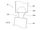
- FIG. 20 is a diagram illustrating a first modification of the swing mechanism.
- the swing mechanism may be a mechanism using a ball joint.
- the swing mechanism 246 has a spherical free end, is formed in an arm shape with a ball portion 246 a attached to the proximal end portion of the distal end side member 43 b of the shaft 43, and the proximal end side member of the shaft 43 And a socket 246b attached to the tip of 43a.
- the inner peripheral surface of the socket 246b forms a substantially hemispherical surface.
- the shape of the inner peripheral surface of the socket 246b is formed substantially the same as the shape of the outer peripheral surface of the ball portion 246a.
- the outer peripheral surface of the ball portion 246a and the inner peripheral surface of the socket 246b form a spherical pair, and the base end side member 43a and the front end side member 43b of the shaft 43 are connected so as to be swingable with at least two degrees of freedom of rotation.
- FIG. 21 is a diagram illustrating a second modification of the swing mechanism.
- the swing mechanism may be a mechanism using an elastic member.
- the rocking mechanism 346 has an elastic portion 346a that connects the proximal end side member 43a and the distal end side member 43b.
- the elastic portion 346a By elastically deforming the elastic portion 346a, the base end side member 43a and the front end side member 43b of the shaft 43 are coupled so as to be swingable with at least two degrees of freedom of rotation.
- FIG. 22 is a diagram illustrating a modified example of an arm provided with a swing mechanism.
- the configuration example in which the swing mechanism 46 is provided in the intermediate portion of the shaft 43 is illustrated, but the present invention is not limited to this.
- the swing mechanism 46 may be provided so as to be interposed between the distal end portion of the translation arm 35 and the instrument 42.
- the first member 46 a of the swing mechanism 46 is directly attached to the distal end portion of the distal end side link 62, and the third member 46 c is directly attached to the instrument 42.
- FIG. 23 is a diagram illustrating a modified example of an arm provided with a swing mechanism.
- the swing mechanism 46 is applied to the surgical operation system 100 including the arm 3 having the translation arm 35, but is not limited thereto. Instead of this, the swing mechanism 46 may be applied to an arm having the linear motion joint 235.
- the surgical operation system 100 includes the platform 5, the plurality of arms 3 (manipulator arms) connected to the platform 5, and the plurality of arms.
- 3 is provided with an instrument 42 and / or an endoscope assembly 41 mounted at the tip of each of the three, and a positioner 7 that supports the platform 5 so that the posture can be changed from a horizontal posture.
- the plurality of arms 3 connected to the platform 5 can be tilted comprehensively. That is, the turning axis Lp (reference axis) of the plurality of arms 3 connected to the platform 5 can be simultaneously tilted by the same angle with respect to the vertical. Thereby, the reference direction D of the instrument 42 or the endoscope assembly 41 attached to the tip of each arm 3 can also be changed by the same angle all at once.
- the positioner 7 has a horizontal articulated horizontal arm 73 (manipulator arm portion) in which the platform 5 is connected to the wrist link 76 (wrist portion).
- the platform 5 is connected to the wrist link 76 of the horizontal arm 73, the inclination of the platform 5 from the horizontal posture can be changed by the operation of the horizontal arm 73.
- the positioner 7 is a column portion (for example, the lifting shaft 72 or the columnar shape) connected to the base 70 installed on the floor of the operating room and the base end portion of the horizontal arm 73. It further has a member 72 ′) and a swing arm 71 that connects the base end portion of the column portion to the base 70 so as to be swingable.
- the positioner 7 can take an aspect in which, for example, the base 70 is disposed below the operating table 111 and the column portion is disposed on the side of the operating table 111. In this way, the positioner 7 can be transformed so as not to obstruct the flow line of the assistant operating around the operating table 111 during the operation.
- the positioner 7 is a rotary joint J71 (first joint) that connects the base end portion of the swing arm 71 to the base 70 so as to be rotatable about a horizontal rotation axis.
- a rotary joint J72 (second joint) for connecting the lift shaft 72 or the base end portion of the columnar member 72 ′ to the distal end portion of the swing arm 71 so as to be rotatable about a horizontal rotation axis.
- the surgical operation system 100 controls the operations of the rotary joint J71 and the rotary joint J72 so that the vertical posture of the elevating shaft 72 or the columnar member 72 ′ is maintained by interlocking the rotary joint J71 and the rotary joint J72.
- a positioner control unit 601 positioner control device
- the horizontal posture of the horizontal arm 73 is maintained by maintaining the vertical posture of the column portion of the positioner 7. Therefore, the positioner 7 can stably support the platform 5 connected to the wrist link 76 (tip portion) of the horizontal arm 73.
- Surgical system 1 Patient side system 2: Operating device 1: Patient side system 2: Operating device 3: Manipulator arm (arm) 3A: Camera arm 3B: Instrument arm 5: Platform 6: Controller 601: Positioner control unit (positioner control device) 7: Positioner 30: Arm body 41: Endoscope assembly 42: Instrument 70: Base 71: Swing arm 72: Elevating shaft (an example of a column) 72 ': Columnar member (an example of a column part) 73: Horizontal arm (manipulator arm) 74: first link 75: second link 76: wrist link J71 to J76: rotary joint O: operator P: patient S: manipulator arm support
Abstract
Description
プラットホームと、
前記プラットホームに連結された複数のマニピュレータアームと、
前記複数のマニピュレータアームの各々の先端部に装着されたインストゥルメントと、
前記プラットホームを水平姿勢から姿勢変化可能に支持するポジショナとを備えることを特徴としている。なお、上記インストゥルメントのうち少なくとも1つが内視鏡カメラアセンブリであってもよい。 A surgical operation system according to one aspect of the present invention includes:
Platform,
A plurality of manipulator arms coupled to the platform;
An instrument attached to the tip of each of the plurality of manipulator arms;
And a positioner that supports the platform so that the posture can be changed from a horizontal posture. Note that at least one of the instruments may be an endoscope camera assembly.
以下、図面を参照しながら、上記外科手術システムについて詳細に説明する。 In the surgical system, the positioner may be connected to a first joint that connects the base end of the swing arm to the base so as to be rotatable about a horizontal rotation axis, and a distal end of the swing arm. And a second joint that pivotally connects the base end of the column portion about a horizontal rotation axis, and the vertical posture of the column portion by interlocking the first joint and the second joint. Further, a positioner control device that controls the operation of the first joint and the second joint may be further provided so that the above-mentioned is maintained.
Hereinafter, the surgical operation system will be described in detail with reference to the drawings.
図1は、本発明の一実施形態に係る外科手術システム100の全体的な構成を示す概略図である。図1に示すように、外科手術システム100は、ロボット支援手術やロボット遠隔手術などのように、医師などの術者Oが患者側システム1を用いて患者Pに内視鏡外科手術を施すシステムである。 [Overview of surgical system]
FIG. 1 is a schematic diagram showing an overall configuration of a
操作装置2は、外科手術システム100と術者Oのインターフェースを構成し、患者側システム1を操作するための装置である。操作装置2は、手術室内において手術台111の傍らに又は手術台111から離れて、或いは、手術室外に設置されている。操作装置2は、術者Oが動作指令を入力するための操作用マニピュレータアーム51や操作ペダル52などの操作入力部50と、内視鏡アセンブリ41で撮影された画像を表示するモニタ53とを含む。術者Oは、モニタ53で患部を視認しながら、操作入力部50を操作して操作装置2に動作指令を入力する。操作装置2に入力された動作指令は、有線又は無線により患者側システム1の後述するコントローラ6に伝達される。 [Configuration example of operating device]
The
患者側システム1は、外科手術システム100と患者Pとのインターフェースを構成する。患者側システム1は、手術室内において患者Pが横たわる手術台111の傍らに配置されている。手術室内は滅菌された滅菌野である。 [Configuration example of patient side system]
The
ここで、ポジショナ7の構成について詳細に説明する。図2は、ポジショナ7の全体的な構成を示す側面図である。 [Example of positioner configuration]
Here, the configuration of the
ここで、アーム3の構成について詳細に説明する。図7では、患者側システム1が備える複数のアーム3のうちの1本の概略構成が示されている。図7に示すように、アーム3は、アーム本体30と、アーム本体30の先端部に連結された並進アーム35とを備え、基端部に対し先端部を3次元空間内で移動させることができるように構成されている。なお、本実施形態では、患者側システム1が具備する複数のアーム3はいずれも同様又は類似の構成を有するが、複数のアーム3のうち少なくとも1本が余と異なる構成を有してもよい。 [Example of arm configuration]
Here, the configuration of the
アーム本体30は、プラットホーム5に着脱可能に取り付けられるベース80と、ベース80から先端部に向けて順次連結された第1リンク81~第6リンク86とを含む。より詳細には、ベース80の先端部に、捩り関節J31を介して第1リンク81の基端部が連結されている。第1リンク81の先端部に、捩り関節J32を介して第2リンク82の基端部が連結されている。第2リンク82の先端部に、曲げ関節J33を介して第3リンク83の基端部が連結されている。第3リンク83の先端部に、捩り関節J34を介して第4リンク84の基端部が連結されている。第4リンク84の先端部に、曲げ関節J35を介して第5リンク85の基端部が連結されている。第5リンク85の先端部に、捩り関節J36を介して第6リンク86の基端部が連結されている。第6リンク86の先端部に、並進アーム35の基端部が連結されている。 [Configuration example of arm body]
The
ここで、プラットホーム5とアーム3との連結構造について説明する。 [Connecting structure between arm and platform]
Here, a connection structure between the
図7に示すように、並進アーム35は、並進アーム35の先端部に取り付けられたホルダ36を基準方向Dに並進移動させることにより、ホルダ36に取り付けられたインストゥルメント42をシャフト43の延在方向に並進移動させる機構である。 [Configuration example of translation arm]
As shown in FIG. 7, the
図18は、並進アームの変形例1を示す図である。上記実施の形態において、並進アーム35は、アーム本体30の先端部30aから基準方向Dにおいてホルダ36に保持されたインストゥルメント42のシャフト43の基端部から先端部に向かう側に位置するように配設されているがこれに限られるものではない。これに代えて、並進アーム335は、並進アーム35は、アーム本体30の先端部30aから基準方向Dにおいてホルダ36に保持されたインストゥルメント42のシャフト43の先端部から基端部に向かう側に位置するように配設されていてもよい。 [
FIG. 18 is a diagram showing a first modification of the translation arm. In the above embodiment, the
図19は、並進アームの変形例2を示す図である。上記実施の形態において、並進アーム35は、基端側リンク61の先端部に先端側リンク62の基端部が取り付けられている構成を例示したがこれに限られるものではない。これに代えて、以下の通り構成されていてもよい。 [Translation arm modification 2]
FIG. 19 is a diagram showing a second modification example of the translation arm. In the said embodiment, although the
図7に示すように、アーム3は、揺動機構46を備えている。揺動機構46は、アーム3とエンドエフェクタ44との間に介在し、基準方向Dを中心とする径方向にシャフト43の先端部、及びエンドエフェクタ44を揺動させる機構である。 [Example of swing mechanism configuration]
As shown in FIG. 7, the
図20は、揺動機構の変形例1を示す図である。揺動機構は、ボール継手を用いた機構であってもよい。 [
FIG. 20 is a diagram illustrating a first modification of the swing mechanism. The swing mechanism may be a mechanism using a ball joint.
図21は、揺動機構の変形例2を示す図である。揺動機構は、弾性を有する部材を用いた機構であってもよい。 [
FIG. 21 is a diagram illustrating a second modification of the swing mechanism. The swing mechanism may be a mechanism using an elastic member.
図22は、揺動機構を備えるアームの変形例を示す図である。上記実施の形態において、揺動機構46がシャフト43の中間部に設けられている構成例を例示したがこれに限られるものではない。これに代えて、揺動機構46は、並進アーム35の先端部とインストゥルメント42との間に介在するように設けられていてもよい。 [Modification Example 1 of Arm with Oscillation Mechanism]
FIG. 22 is a diagram illustrating a modified example of an arm provided with a swing mechanism. In the above-described embodiment, the configuration example in which the
図23は、揺動機構を備えるアームの変形例を示す図である。上記実施の形態1において、揺動機構46は、並進アーム35を有するアーム3を備える外科手術システム100に適用したがこれに限られるものではない。これに代えて、揺動機構46は、直動関節235を有するアームに適用してもよい。 [Modification Example 2 of Arm with Oscillation Mechanism]
FIG. 23 is a diagram illustrating a modified example of an arm provided with a swing mechanism. In the first embodiment, the
以上に説明したように、本実施形態に係る外科手術システム100(特に、そのうち患者側システム1)は、プラットホーム5と、プラットホーム5に連結された複数のアーム3(マニピュレータアーム)と、複数のアーム3の各々の先端部に装着されたインストゥルメント42及び/又は内視鏡アセンブリ41と、プラットホーム5を水平姿勢から姿勢変化可能に支持するポジショナ7とを備えている。 [Summary]
As described above, the
1 :患者側システム
2 :操作装置
1 :患者側システム
2 :操作装置
3 :マニピュレータアーム(アーム)
3A :カメラアーム
3B :インストゥルメントアーム
5 :プラットホーム
6 :コントローラ
601 :ポジショナ制御部(ポジショナ制御装置)
7 :ポジショナ
30 :アーム本体
41 :内視鏡アセンブリ
42 :インストゥルメント
70 :ベース
71 :揺動アーム
72 :昇降軸(柱部の一例)
72' :柱状部材(柱部の一例)
73 :水平アーム(マニピュレータアーム部)
74 :第1リンク
75 :第2リンク
76 :手首リンク
J71~J76 :回転関節
O :術者
P :患者
S :マニピュレータアーム支持体 DESCRIPTION OF SYMBOLS 100: Surgical system 1: Patient side system 2: Operating device 1: Patient side system 2: Operating device 3: Manipulator arm (arm)
3A:
7: Positioner 30: Arm body 41: Endoscope assembly 42: Instrument 70: Base 71: Swing arm 72: Elevating shaft (an example of a column)
72 ': Columnar member (an example of a column part)
73: Horizontal arm (manipulator arm)
74: first link 75: second link 76: wrist link J71 to J76: rotary joint O: operator P: patient S: manipulator arm support
Claims (4)
- プラットホームと、
前記プラットホームに連結された複数のマニピュレータアームと、
前記複数のマニピュレータアームの各々の先端部に装着されたインストゥルメントと、
前記プラットホームを水平姿勢から姿勢変化可能に支持するポジショナとを備える、
外科手術システム。 Platform,
A plurality of manipulator arms coupled to the platform;
An instrument attached to the tip of each of the plurality of manipulator arms;
A positioner that supports the platform so that the posture can be changed from a horizontal posture;
Surgical system. - 前記ポジショナは、手首部に前記プラットホームが連結された水平多関節形のマニピュレータアーム部を有する、
請求項1に記載の外科手術システム。 The positioner has a horizontal articulated manipulator arm portion with the platform connected to a wrist.
The surgical system according to claim 1. - 前記ポジショナは、手術室の床に設置されたベースと、前記マニピュレータアーム部の基端部と連結された柱部と、前記ベースに対し前記柱部の基端部を揺動可能に連結する揺動アームとを、更に有する、
請求項2に記載の外科手術システム。 The positioner includes a base installed on the floor of the operating room, a column connected to the base end of the manipulator arm, and a swing for connecting the base end of the column to the base in a swingable manner. A moving arm,
The surgical operation system according to claim 2. - 前記ポジショナは、前記ベースに対し前記揺動アームの基端部を水平な回転軸回りに回動可能に連結する第1関節と、前記揺動アームの先端部に対し前記柱部の基端部を水平な回転軸回りに回動可能に連結する第2関節とを有し、
前記第1関節と前記第2関節が連動することによって前記柱部の垂直な姿勢が維持されるように、前記第1関節及び前記第2関節の動作を制御する、ポジショナ制御装置を更に備える、
請求項3に記載の外科手術システム。 The positioner includes a first joint that connects the base end of the swing arm to the base so as to be rotatable about a horizontal rotation axis, and a base end of the column portion with respect to the tip of the swing arm And a second joint for pivotally connecting about a horizontal rotation axis,
A positioner control device for controlling operations of the first joint and the second joint so that the vertical posture of the column is maintained by interlocking the first joint and the second joint;
The surgical operation system according to claim 3.
Priority Applications (4)
| Application Number | Priority Date | Filing Date | Title |
|---|---|---|---|
| EP16872610.7A EP3388015A4 (en) | 2015-12-11 | 2016-11-30 | Surgical operation system |
| KR1020187019126A KR20180090351A (en) | 2015-12-11 | 2016-11-30 | Surgical Surgical System |
| US16/060,982 US20180360553A1 (en) | 2015-12-11 | 2016-11-30 | Surgical system |
| CN201680072222.1A CN108289715A (en) | 2015-12-11 | 2016-11-30 | Surgical system |
Applications Claiming Priority (2)
| Application Number | Priority Date | Filing Date | Title |
|---|---|---|---|
| JP2015-242699 | 2015-12-11 | ||
| JP2015242699A JP6654884B2 (en) | 2015-12-11 | 2015-12-11 | Surgery system |
Publications (1)
| Publication Number | Publication Date |
|---|---|
| WO2017098708A1 true WO2017098708A1 (en) | 2017-06-15 |
Family
ID=59013891
Family Applications (1)
| Application Number | Title | Priority Date | Filing Date |
|---|---|---|---|
| PCT/JP2016/005034 WO2017098708A1 (en) | 2015-12-11 | 2016-11-30 | Surgical operation system |
Country Status (6)
| Country | Link |
|---|---|
| US (1) | US20180360553A1 (en) |
| EP (1) | EP3388015A4 (en) |
| JP (1) | JP6654884B2 (en) |
| KR (1) | KR20180090351A (en) |
| CN (1) | CN108289715A (en) |
| WO (1) | WO2017098708A1 (en) |
Cited By (1)
| Publication number | Priority date | Publication date | Assignee | Title |
|---|---|---|---|---|
| EP3678575A4 (en) * | 2017-09-06 | 2021-07-07 | Covidien LP | Mobile surgical control console |
Families Citing this family (5)
| Publication number | Priority date | Publication date | Assignee | Title |
|---|---|---|---|---|
| US20200129251A1 (en) * | 2018-10-31 | 2020-04-30 | Ss Innovations China Co., Ltd. | Omni-directional wheels for a robotic surgical cart |
| JP7153335B2 (en) * | 2019-01-29 | 2022-10-14 | リバーフィールド株式会社 | Surgery support device |
| JP7369789B2 (en) * | 2019-12-05 | 2023-10-26 | 川崎重工業株式会社 | Surgical robot, surgical system and control method |
| JP7393383B2 (en) | 2021-05-24 | 2023-12-06 | 川崎重工業株式会社 | Operation method of surgical support robot and articulated robot |
| US20230404692A1 (en) * | 2022-06-21 | 2023-12-21 | Mazor Robotics Ltd. | Cost effective robotic system architecture |
Citations (8)
| Publication number | Priority date | Publication date | Assignee | Title |
|---|---|---|---|---|
| JP2002361578A (en) * | 2001-06-05 | 2002-12-18 | Osaka Kiko Co Ltd | Working robot |
| US20030208189A1 (en) * | 2001-10-19 | 2003-11-06 | Payman Gholam A. | Integrated system for correction of vision of the human eye |
| JP2004208922A (en) * | 2002-12-27 | 2004-07-29 | Olympus Corp | Medical apparatus, medical manipulator and control process for medical apparatus |
| US20040261179A1 (en) * | 1999-08-03 | 2004-12-30 | Intuitive Surgical, Inc. | Ceiling and floor mounted surgical robot set-up arms |
| JP2012005557A (en) * | 2010-06-23 | 2012-01-12 | Terumo Corp | Medical robot system |
| JP2012143589A (en) | 2005-01-24 | 2012-08-02 | Intuitive Surgical Inc | Modular manipulator support for robotic |
| WO2014199414A1 (en) * | 2013-06-13 | 2014-12-18 | テルモ株式会社 | Medical manipulator, and control method therefor |
| JP2015530906A (en) * | 2012-08-15 | 2015-10-29 | インテュイティブ サージカル オペレーションズ, インコーポレイテッド | Mobile surgical mounting platform controlled by manual robot arm movement |
Family Cites Families (17)
| Publication number | Priority date | Publication date | Assignee | Title |
|---|---|---|---|---|
| JPH01210280A (en) * | 1988-02-19 | 1989-08-23 | Tokico Ltd | Industrial robot |
| US6659939B2 (en) * | 1998-11-20 | 2003-12-09 | Intuitive Surgical, Inc. | Cooperative minimally invasive telesurgical system |
| US6565554B1 (en) * | 1999-04-07 | 2003-05-20 | Intuitive Surgical, Inc. | Friction compensation in a minimally invasive surgical apparatus |
| FR2829016B1 (en) * | 2001-09-03 | 2007-01-19 | Bertin Virgile Claude Nahum | SURGICAL DEVICE FOR GUIDING MILLING INSTRUMENTS, DRILLING, BORING OR CUTTING BONE TISSUES |
| US8010180B2 (en) * | 2002-03-06 | 2011-08-30 | Mako Surgical Corp. | Haptic guidance system and method |
| US8079950B2 (en) * | 2005-09-29 | 2011-12-20 | Intuitive Surgical Operations, Inc. | Autofocus and/or autoscaling in telesurgery |
| JP2007117291A (en) * | 2005-10-26 | 2007-05-17 | Olympus Medical Systems Corp | Stereoscopic observation apparatus |
| EP1915963A1 (en) * | 2006-10-25 | 2008-04-30 | The European Atomic Energy Community (EURATOM), represented by the European Commission | Force estimation for a minimally invasive robotic surgery system |
| US8945148B2 (en) * | 2007-06-13 | 2015-02-03 | Intuitive Surgical Operations, Inc. | Surgical system instrument manipulator |
| US8400094B2 (en) * | 2007-12-21 | 2013-03-19 | Intuitive Surgical Operations, Inc. | Robotic surgical system with patient support |
| DE102008041260A1 (en) * | 2008-08-14 | 2010-02-25 | Deutsches Zentrum für Luft- und Raumfahrt e.V. | Method for operating a medical robot, medical robot and medical workstation |
| CN104334112B (en) * | 2012-06-01 | 2017-10-27 | 直观外科手术操作公司 | Multiport surgical robot system framework |
| CN113397655A (en) * | 2012-11-14 | 2021-09-17 | 直观外科手术操作公司 | System and method for dual control surgical instrument |
| DE102012025102A1 (en) * | 2012-12-20 | 2014-06-26 | avateramedical GmBH | Endoscope with a multi-camera system for minimally invasive surgery |
| DE102012025100A1 (en) * | 2012-12-20 | 2014-06-26 | avateramedical GmBH | Decoupled multi-camera system for minimally invasive surgery |
| KR20140112601A (en) * | 2013-03-11 | 2014-09-24 | 삼성전자주식회사 | Endoscopic surgical instrument |
| DE102013205494B4 (en) * | 2013-03-27 | 2021-02-18 | Siemens Healthcare Gmbh | X-ray machine |
-
2015
- 2015-12-11 JP JP2015242699A patent/JP6654884B2/en active Active
-
2016
- 2016-11-30 KR KR1020187019126A patent/KR20180090351A/en not_active Application Discontinuation
- 2016-11-30 CN CN201680072222.1A patent/CN108289715A/en active Pending
- 2016-11-30 WO PCT/JP2016/005034 patent/WO2017098708A1/en active Application Filing
- 2016-11-30 US US16/060,982 patent/US20180360553A1/en not_active Abandoned
- 2016-11-30 EP EP16872610.7A patent/EP3388015A4/en not_active Withdrawn
Patent Citations (8)
| Publication number | Priority date | Publication date | Assignee | Title |
|---|---|---|---|---|
| US20040261179A1 (en) * | 1999-08-03 | 2004-12-30 | Intuitive Surgical, Inc. | Ceiling and floor mounted surgical robot set-up arms |
| JP2002361578A (en) * | 2001-06-05 | 2002-12-18 | Osaka Kiko Co Ltd | Working robot |
| US20030208189A1 (en) * | 2001-10-19 | 2003-11-06 | Payman Gholam A. | Integrated system for correction of vision of the human eye |
| JP2004208922A (en) * | 2002-12-27 | 2004-07-29 | Olympus Corp | Medical apparatus, medical manipulator and control process for medical apparatus |
| JP2012143589A (en) | 2005-01-24 | 2012-08-02 | Intuitive Surgical Inc | Modular manipulator support for robotic |
| JP2012005557A (en) * | 2010-06-23 | 2012-01-12 | Terumo Corp | Medical robot system |
| JP2015530906A (en) * | 2012-08-15 | 2015-10-29 | インテュイティブ サージカル オペレーションズ, インコーポレイテッド | Mobile surgical mounting platform controlled by manual robot arm movement |
| WO2014199414A1 (en) * | 2013-06-13 | 2014-12-18 | テルモ株式会社 | Medical manipulator, and control method therefor |
Non-Patent Citations (1)
| Title |
|---|
| See also references of EP3388015A4 |
Cited By (1)
| Publication number | Priority date | Publication date | Assignee | Title |
|---|---|---|---|---|
| EP3678575A4 (en) * | 2017-09-06 | 2021-07-07 | Covidien LP | Mobile surgical control console |
Also Published As
| Publication number | Publication date |
|---|---|
| KR20180090351A (en) | 2018-08-10 |
| JP6654884B2 (en) | 2020-02-26 |
| EP3388015A4 (en) | 2019-07-31 |
| EP3388015A1 (en) | 2018-10-17 |
| US20180360553A1 (en) | 2018-12-20 |
| CN108289715A (en) | 2018-07-17 |
| JP2017104453A (en) | 2017-06-15 |
Similar Documents
| Publication | Publication Date | Title |
|---|---|---|
| WO2017098707A1 (en) | Surgical operation system, manipulator arm, and manipulator arm support | |
| WO2017099200A1 (en) | Surgical system | |
| WO2017098708A1 (en) | Surgical operation system | |
| KR102322620B1 (en) | Redundant axis and degree of freedom for hardware-constrained remote center robotic manipulator | |
| ES2689093T3 (en) | Medical robotic system with manipulator arm of the cylindrical coordinate type | |
| CN106102640A (en) | For making surgical instruments and the method that remotely operation actuator engages | |
| US20230000572A1 (en) | Surgical system and method of controlling surgical manipulator arm | |
| JP6831642B2 (en) | Surgical system | |
| US11717366B2 (en) | Medical manipulator | |
| WO2017099242A1 (en) | Surgical system | |
| US11648067B2 (en) | Medical manipulator and surgical system including the same | |
| JP6894954B2 (en) | Medical manipulator and surgical system equipped with it | |
| JP6567771B2 (en) | Manipulator system | |
| JP2020058792A (en) | Patient-side apparatus of surgical system and surgical system |
Legal Events
| Date | Code | Title | Description |
|---|---|---|---|
| 121 | Ep: the epo has been informed by wipo that ep was designated in this application |
Ref document number: 16872610 Country of ref document: EP Kind code of ref document: A1 |
|
| NENP | Non-entry into the national phase |
Ref country code: DE |
|
| ENP | Entry into the national phase |
Ref document number: 20187019126 Country of ref document: KR Kind code of ref document: A |
|
| WWE | Wipo information: entry into national phase |
Ref document number: 1020187019126 Country of ref document: KR |
|
| WWE | Wipo information: entry into national phase |
Ref document number: 2016872610 Country of ref document: EP |