WO2017094567A1 - Tracking device - Google Patents
Tracking device Download PDFInfo
- Publication number
- WO2017094567A1 WO2017094567A1 PCT/JP2016/084649 JP2016084649W WO2017094567A1 WO 2017094567 A1 WO2017094567 A1 WO 2017094567A1 JP 2016084649 W JP2016084649 W JP 2016084649W WO 2017094567 A1 WO2017094567 A1 WO 2017094567A1
- Authority
- WO
- WIPO (PCT)
- Prior art keywords
- tracking
- moving
- moving body
- unit
- mobile
- Prior art date
Links
Images


Classifications
-
- G—PHYSICS
- G06—COMPUTING; CALCULATING OR COUNTING
- G06T—IMAGE DATA PROCESSING OR GENERATION, IN GENERAL
- G06T7/00—Image analysis
- G06T7/20—Analysis of motion
- G06T7/207—Analysis of motion for motion estimation over a hierarchy of resolutions
-
- G—PHYSICS
- G06—COMPUTING; CALCULATING OR COUNTING
- G06T—IMAGE DATA PROCESSING OR GENERATION, IN GENERAL
- G06T7/00—Image analysis
- G06T7/20—Analysis of motion
- G06T7/254—Analysis of motion involving subtraction of images
-
- G—PHYSICS
- G06—COMPUTING; CALCULATING OR COUNTING
- G06T—IMAGE DATA PROCESSING OR GENERATION, IN GENERAL
- G06T7/00—Image analysis
- G06T7/20—Analysis of motion
- G06T7/269—Analysis of motion using gradient-based methods
-
- G—PHYSICS
- G06—COMPUTING; CALCULATING OR COUNTING
- G06T—IMAGE DATA PROCESSING OR GENERATION, IN GENERAL
- G06T7/00—Image analysis
- G06T7/20—Analysis of motion
- G06T7/277—Analysis of motion involving stochastic approaches, e.g. using Kalman filters
-
- G—PHYSICS
- G06—COMPUTING; CALCULATING OR COUNTING
- G06T—IMAGE DATA PROCESSING OR GENERATION, IN GENERAL
- G06T7/00—Image analysis
- G06T7/20—Analysis of motion
- G06T7/292—Multi-camera tracking
-
- G—PHYSICS
- G06—COMPUTING; CALCULATING OR COUNTING
- G06V—IMAGE OR VIDEO RECOGNITION OR UNDERSTANDING
- G06V20/00—Scenes; Scene-specific elements
- G06V20/50—Context or environment of the image
- G06V20/56—Context or environment of the image exterior to a vehicle by using sensors mounted on the vehicle
- G06V20/58—Recognition of moving objects or obstacles, e.g. vehicles or pedestrians; Recognition of traffic objects, e.g. traffic signs, traffic lights or roads
-
- G—PHYSICS
- G08—SIGNALLING
- G08G—TRAFFIC CONTROL SYSTEMS
- G08G1/00—Traffic control systems for road vehicles
- G08G1/16—Anti-collision systems
-
- G—PHYSICS
- G08—SIGNALLING
- G08G—TRAFFIC CONTROL SYSTEMS
- G08G1/00—Traffic control systems for road vehicles
- G08G1/16—Anti-collision systems
- G08G1/166—Anti-collision systems for active traffic, e.g. moving vehicles, pedestrians, bikes
-
- H—ELECTRICITY
- H04—ELECTRIC COMMUNICATION TECHNIQUE
- H04N—PICTORIAL COMMUNICATION, e.g. TELEVISION
- H04N7/00—Television systems
- H04N7/18—Closed-circuit television [CCTV] systems, i.e. systems in which the video signal is not broadcast
-
- H—ELECTRICITY
- H04—ELECTRIC COMMUNICATION TECHNIQUE
- H04N—PICTORIAL COMMUNICATION, e.g. TELEVISION
- H04N7/00—Television systems
- H04N7/18—Closed-circuit television [CCTV] systems, i.e. systems in which the video signal is not broadcast
- H04N7/183—Closed-circuit television [CCTV] systems, i.e. systems in which the video signal is not broadcast for receiving images from a single remote source
-
- B—PERFORMING OPERATIONS; TRANSPORTING
- B60—VEHICLES IN GENERAL
- B60R—VEHICLES, VEHICLE FITTINGS, OR VEHICLE PARTS, NOT OTHERWISE PROVIDED FOR
- B60R2300/00—Details of viewing arrangements using cameras and displays, specially adapted for use in a vehicle
- B60R2300/80—Details of viewing arrangements using cameras and displays, specially adapted for use in a vehicle characterised by the intended use of the viewing arrangement
- B60R2300/8093—Details of viewing arrangements using cameras and displays, specially adapted for use in a vehicle characterised by the intended use of the viewing arrangement for obstacle warning
-
- G—PHYSICS
- G06—COMPUTING; CALCULATING OR COUNTING
- G06T—IMAGE DATA PROCESSING OR GENERATION, IN GENERAL
- G06T2207/00—Indexing scheme for image analysis or image enhancement
- G06T2207/10—Image acquisition modality
- G06T2207/10016—Video; Image sequence
-
- G—PHYSICS
- G06—COMPUTING; CALCULATING OR COUNTING
- G06T—IMAGE DATA PROCESSING OR GENERATION, IN GENERAL
- G06T2207/00—Indexing scheme for image analysis or image enhancement
- G06T2207/20—Special algorithmic details
- G06T2207/20076—Probabilistic image processing
-
- G—PHYSICS
- G06—COMPUTING; CALCULATING OR COUNTING
- G06T—IMAGE DATA PROCESSING OR GENERATION, IN GENERAL
- G06T2207/00—Indexing scheme for image analysis or image enhancement
- G06T2207/20—Special algorithmic details
- G06T2207/20212—Image combination
- G06T2207/20224—Image subtraction
-
- G—PHYSICS
- G06—COMPUTING; CALCULATING OR COUNTING
- G06T—IMAGE DATA PROCESSING OR GENERATION, IN GENERAL
- G06T2207/00—Indexing scheme for image analysis or image enhancement
- G06T2207/30—Subject of image; Context of image processing
- G06T2207/30241—Trajectory
-
- G—PHYSICS
- G06—COMPUTING; CALCULATING OR COUNTING
- G06T—IMAGE DATA PROCESSING OR GENERATION, IN GENERAL
- G06T2207/00—Indexing scheme for image analysis or image enhancement
- G06T2207/30—Subject of image; Context of image processing
- G06T2207/30248—Vehicle exterior or interior
- G06T2207/30252—Vehicle exterior; Vicinity of vehicle
- G06T2207/30261—Obstacle
Definitions
- the present invention relates to a tracking device.
- the tracking device calculates an optical flow using an image input unit to which an image obtained by photographing by an imaging unit is input, and a plurality of images input to the image input unit.
- a first moving body detecting unit that detects the position and moving direction of the moving body based on the calculated optical flow, and a position and moving direction of the moving body based on the plurality of overhead images generated based on the plurality of images.
- a second moving body detector that detects the position of the moving body and a moving direction by integrating the detection results of the first moving body detector and the second moving body detector;
- a tracking moving body determination unit that determines a moving body to be tracked based on a detection result of the third moving body detection unit, and an estimation that estimates a future position and a moving direction of the tracking mobile body determined by the tracking mobile body determination unit
- second to third moving body tests A tracking unit that tracks the tracking mobile body using any one of the positions of the respective mobile bodies detected by the unit and the estimated position estimated by the estimation unit and identifies the position of the tracking mobile body .
- tracking of a moving object can be continued even when detection of a moving object using an optical flow or detection of a moving object using an overhead image is impossible.
- FIG. 9A illustrates an example of a planar projection image obtained from an image captured by the camera 12 at time t ⁇ t
- FIG. 9B illustrates a planar projection image obtained from an image captured by the camera 12 at time t.
- FIG. 9C is a diagram showing an example of the result of detecting only the optical flow generated along with the movement of the pedestrian X1.
- the figure showing an example of the detected 1st candidate field The flowchart which shows operation
- FIGS. 12A to 12E are diagrams for explaining the processing in steps S601 to S604 in FIG.
- FIGS. 13A to 13C are diagrams illustrating a process of calculating the closest point Ha from the calculated second candidate region.
- FIG. 15A is a diagram illustrating an example of determination in step S1306 in FIG. 14, and
- FIG. 15B is a diagram illustrating an example of processing in step S1308 in FIG.
- a flowchart showing the operation of the tracking processing unit 55 Flowchart showing the operation of the tracking processing unit 55 continued from FIG. Flowchart showing the operation of the tracking processing unit 55 continued from FIG.
- the figure which shows the list of the update process of the tracking mobile body DMO by the tracking process part 55 Flowchart showing the operation of the tracking mobile body determination unit 54
- 24A shows a case where the vehicle in front of the vehicle 10 moves to the right in the figure
- FIG. 24B shows a case in which the vehicle right in front of the vehicle 10 moves to the left in the figure.
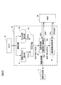
- FIG. 1 is a diagram illustrating a configuration of a vehicle 10 on which the image processing ECU 18 is mounted.
- the vehicle 10 will be described later with the wheel speed sensor 20 for calculating the amount of movement of the vehicle 10, the steering angle sensor 22 for calculating the traveling direction of the vehicle 10, and the outputs of the wheel speed sensor 20 and the steering angle sensor 22.
- a sensor interface 24 that transmits to the image processing ECU 18, a camera 12 that captures the surroundings of the vehicle 10, a camera interface 14 that transmits images obtained by the camera 12 to the image processing ECU 18, and a moving path of the vehicle 10.
- a memory 26 that is a volatile storage area, a monitor 34 that presents information to the user of the vehicle 10, and a display control unit 3 that controls the monitor 34
- a vehicle behavior control ECU30 outputs the operation command to the brake actuator 36.
- the sensor interface 24, the camera interface 14, the route generation unit 17, the image processing ECU 18, the display control unit 32, and the vehicle behavior control ECU 30 are connected by a system bus 16.
- the camera 12 shoots every predetermined time ⁇ t, for example, every 17 milliseconds, and outputs information obtained by the shooting to the camera interface 14.
- the camera interface 14 uses the information received from the camera 12, performs correction in consideration of the aberration of the lens attached to the camera 12, creates an image, and transmits the image to the image processing ECU 18. Therefore, every time the camera 12 performs photographing, the created image is output from the camera interface 14 to the image processing ECU 18.
- an image output from the camera interface 14 to the image processing ECU 18 is referred to as a “captured image”.
- the image processing ECU 18 includes a communication unit 18a, a CPU, a ROM, and a RAM, and develops and executes a program stored in the ROM on the RAM.
- the communication unit 18 a communicates with the camera interface 14 via the system bus 16 and receives an image obtained by the camera 12 shooting.
- the program stored in the ROM is executed every time a photographed image is input from the camera interface 14.
- This program stores a part of data necessary for execution in the memory 26.
- a part of the program may be realized by hardware, or may be stored only in the RAM provided in the image processing ECU 18 without using the memory 26.
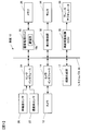
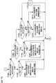
- FIG. 2 shows the functions of the program executed by the image processing ECU 18 as function blocks, and shows the correlation between the function blocks.
- the image processing ECU 18 associates the movement vector calculation unit 51 to which the photographed image is input, the foot position calculation unit 52 to which the photographed image is similarly input, and the calculation results of the movement vector calculation unit 51 and the foot position calculation unit 52.
- the first detection result RES1, the second detection result RES2, the integrated object MOF, the moving object candidate CPE, and the tracking moving object DMO described below are storage areas secured in the memory 26. However, information stored in the storage area is also referred to by the same name.
- the image processing ECU 18 performs a series of processes shown in FIG. 2 each time a captured image is input.
- the first detection result RES1, the second detection result RES2, and the integrated object MOF are calculated every time a captured image is input.
- the moving object candidate CPE and the tracking moving object DMO are stored in the memory 26 and updated by the tracking moving object determining unit 54 and the tracking processing unit 55 every time a captured image is input.
- nothing is stored in the moving object candidate CPE and the tracking moving object DMO, and information is stored in the moving object candidate CPE and the tracking moving object DMO by the process described later.
- the movement vector calculation unit 51 receives a photographed image from the camera 12, calculates an optical flow using the latest photographed image and the immediately preceding photographed image, and is an area that may be a moving body (hereinafter, a first candidate area). ) Is detected. Then, the detected coordinates and movement direction of the first candidate region are output to the first detection result RES1.
- the first detection result RES1 has the same number of records as the first candidate areas detected by the movement vector calculation unit 51.
- the first detection result RES1 is, for example, as follows.
- FIG. 3 is a diagram illustrating an example of the first detection result RES1.
- the first detection result RES1 is composed of one or more records, and the coordinates of the first candidate area and the moving direction of the first candidate area are recorded in each record.
- the first candidate area is defined by a rectangle, and its coordinates are specified by the upper left coordinates and the lower right coordinates.
- the first candidate region is not limited to a rectangle, and may be an ellipse or an arbitrarily shaped region.
- the moving direction of the first candidate region may include a component in the depth direction, that is, a direction away from / approaching from the camera 12 as well as the left and right, and the moving direction may be expressed by an angle of 0 to 360 degrees. Returning to FIG. 2, the description will be continued.
- the foot position calculation unit 52 creates a bird's-eye view image from each of the latest photographed image and the immediately preceding photographed image, and detects an area that may be a moving body (hereinafter, a second candidate area) from the difference. Then, the coordinates in the overhead image of the center of gravity G of the detected second candidate region and the coordinates in the overhead image of the closest point Ha with the vehicle 10 are output to the second detection result RES2.
- the second detection result RES2 has the same number of records as the second candidate areas detected by the foot position calculation unit 52.
- the foot position calculation unit 52 calculates the closest point Hb corresponding to the closest point Ha in the plane conversion image by a procedure reverse to the creation of the bird's-eye view image, and similarly outputs it to the second detection result RES2.
- the second detection result RES2 has, for example, the following configuration.
- FIG. 4 is a diagram illustrating an example of the second detection result RES2.
- the second detection result RES2 includes one or more records, and information on the second candidate area in the overhead image and information on the second candidate area in the front image are recorded in each record.
- the information of the second candidate area in the bird's-eye view image is the coordinates of the center of gravity G of the second candidate area and the coordinates of the closest point Ha to the vehicle 10 in the second candidate area, that is, the coordinates of the closest point Ha.
- the information on the second candidate area in the front image is coordinates corresponding to the closest point Ha in the overhead image, and is obtained by coordinate conversion of the coordinates of the closest point Ha in the overhead image.
- the associating unit 53 associates the first candidate area detected by the movement vector calculating unit 51 with the second candidate area detected by the foot position calculating unit 52, and the associated area (hereinafter, referred to as “corresponding region”). Integration candidate area) and the movement direction of the integration candidate area are stored in the integrated object MOF. That is, the association unit 53 receives the first detection result RES1 and the second detection result RES2 in which the first candidate area is recorded, and outputs the integrated object MOF. Further, the associating unit 53 deletes and outputs the record associated with the first detection result RES1 and the second detection result RES2.
- the association unit 53 outputs the records.
- the number of each record is as follows. That is, the integrated object MOF has 2 records, the first detection result RES1 has 1 record, and the second detection result RES2 has 3 records.
- the integrated object MOF has the following configuration.
- FIG. 5 is a diagram illustrating an example of the integrated object MOF.
- the integrated object MOF is composed of one or more records, and in each record, the coordinates of the integration candidate area in the front image and the moving direction of the integration candidate area are recorded.
- the integration candidate area is defined by a rectangle, and its coordinates are specified by the upper left coordinates and the lower right coordinates.
- the integration candidate area is not limited to a rectangle, and may be an ellipse or an area having an arbitrary shape.
- the moving direction of the integration candidate region may include not only the right and left but also a depth direction, that is, a component in a direction away / approaching from the camera 12. Returning to FIG. 2, the description will be continued.
- the tracking processing unit 55 includes an estimation unit 55a and a tracking unit 55b.
- the estimation unit 55a performs prediction of the position of the moving body among the processes described below, and the tracking unit 55b performs other processes.
- the tracking processing unit 55 reads the integrated object MOF, the first detection result RES1, and the first detection result RES1 output from the association unit 53, and further reads the tracking mobile body DMO from the memory 26.
- information of the mobile body being tracked is stored as one record for each mobile body. An example of the tracking mobile DMO will be described later.
- the tracking processing unit 55 predicts the position of the mobile body stored in the tracking mobile body DMO, updates the position of the mobile body, that is, specifies the position of the mobile body, deletes the mobile body from the tracking target, that is, the tracking mobile body DMO. Delete a specific record from the mobile station, output information related to the moving object to the route generation unit 17, and change the tracking certainty described later.
- the updated tracking mobile DMO is stored in the memory 26.
- the tracking processing unit 55 outputs the first detection result RES1 and the second detection result RES2 without being changed by performing processing described later on the integrated object MOF.
- the tracking certainty is an index indicating the probability of tracking processing for each moving object, and is deleted from the tracking moving object DMO when the tracking certainty becomes a predetermined value or less.
- the tracking certainty is represented by, for example, 0 to 100, and is increased or decreased by a process described later from an initial value of 50. When the tracking certainty becomes 0, the tracking certainty is deleted from the tracking mobile body DMO.
- FIG. 6 is a diagram illustrating an example of the tracking mobile body DMO.
- the tracking mobile body DMO is composed of one or more records, and each record includes a predicted position that is a coordinate of a front image in the next frame of the mobile body, a speed of the mobile body, a moving direction of the mobile body, a tracking certainty factor, and
- the update position which is the coordinates of the front image in the current frame of the moving body, that is, the position of the identified moving body is recorded.
- the integration candidate area is defined by a rectangle, and its coordinates are specified by the upper left coordinates and the lower right coordinates. However, the integration candidate area is not limited to a rectangle, and may be an ellipse or an area having an arbitrary shape.
- the speed of the moving body is recorded on the premise that the moving body performs a constant velocity motion.
- the moving direction of the moving body may include not only the right and left but also a depth direction, that is, a component in a direction away / approaching from the camera 12.
- the tracking mobile body determination unit 54 reads the integrated object MOF, the first detection result RES1, and the second detection result RES2 output from the tracking processing unit 55, and further reads the mobile body candidate CPE from the memory 26.
- the moving object candidate CPE information related to a moving object candidate area that is a candidate for tracking is stored as one record for each candidate. An example of the moving object candidate CPE will be described later.
- the tracking mobile body determination unit 54 adds or deletes records from the mobile body candidate CPE, adds records that satisfy the criteria described later to the tracking mobile body DMO, and increases or decreases the mobile body reliability described later.
- the moving object certainty factor is expressed by, for example, an integer, and is increased or decreased by a process described later from an initial value of 50. When the moving object certainty factor becomes 0 or less, the record is deleted from the integrated object MOF, and the moving object certainty factor is 100. If exceeded, the record is moved from the integrated object MOF to the tracking mobile body DMO.
- FIG. 7 is a diagram illustrating an example of the moving object candidate CPE.
- the moving object candidate CPE is composed of one or more records, and each record includes a plurality of predicted positions in the next frame of the moving object candidate area, the speed of the moving object candidate area, the moving direction of the moving object candidate area, and the moving object.
- the confidence is recorded.
- the expected position of the moving object candidate area is defined by a rectangle, and its coordinates are specified by the upper left coordinates and the lower right coordinates.
- the predicted position is not limited to a rectangle, and may be an ellipse or an arbitrarily shaped region.
- the moving direction of the moving object candidate region may include not only the right and left but also a depth direction, that is, a component in a direction away / approaching from the camera 12.
- the moving object candidate CPE and the tracking moving object DMO are stored in the memory 26.
- the moving object candidate CPE and the tracking moving object DMO do not include a record.
- a record is added to the moving object candidate CPE and the tracking moving object DMO by the processing of the tracking moving object determining unit 54. That is, a record is added by the tracking mobile body determination unit 54 to all of the mobile body candidate CPE and the tracking mobile body DMO stored in the memory 26.
- FIG. 8 is a flowchart showing the operation of the movement vector calculation unit 51.
- step S301 the captured image received from the camera 12 is converted into a planar projection image projected onto a virtual plane that stands vertically. Then, an optical flow is detected from an image obtained by converting the latest photographed image into a planar projection image and an image obtained by transforming the immediately preceding photographed image into a planar projection image. The optical flow is calculated as follows, for example.
- one of the two images used for calculating the optical flow is divided into a plurality of small areas, and a small area (the other small area) whose gray value distribution is very similar to each small area is obtained.
- a process of searching from the other image is performed, and one of the associated small areas is set as the start point of the optical flow, and the other small area is set as the end point of the optical flow.
- the process proceeds to step S302.
- step S302 using the outputs of the wheel speed sensor 20 and the steering angle sensor 22 output from the sensor interface 24, it is expected to occur along with the movement of the vehicle 10 during the time ⁇ t from the previous image capture to the present time.
- the optical flow to be calculated is calculated.
- step S303 the difference between the optical flow calculated in step S301 and the optical flow calculated in step S302 is calculated.
- an optical flow that eliminates the influence of the movement of the vehicle 10 is calculated.
- step S304 proceeds to step S304.
- step S304 using the optical flow calculated in step S303, an area that may be a mobile object, that is, a first candidate area is detected. For example, among the small areas constituting the end points of the optical flows, when the optical flows are close to each other and have the same length in the same direction, the small areas that are the end points of the plurality of optical flows are Merged and detected as one first candidate region. Next, the process proceeds to step S305.
- step S305 each first candidate area detected in step S304 is labeled. However, if the area of the area is smaller than a predetermined area, the area may be regarded as noise and may not be labeled.
- step S306 for each first candidate region labeled in step S305, a rectangle circumscribing the first candidate region is set, and the upper left and lower right coordinates of the rectangle are registered in the first detection result RES1. Further, the moving direction of the first candidate area is detected using the optical flow calculated in step S303, and the detected moving direction is also registered in the first detection result RES1.
- the first detection result RES1 is registered in a different record for each labeled first candidate area. For example, when five first candidate areas are labeled, five records are registered in the first detection result RES1.
- the kth record of the first detection result RES1 is denoted as RES1 [k].
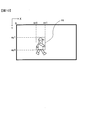
- FIGS. 9A to 9C are diagrams for explaining a processing example of the movement vector calculation unit 51.
- FIG. 9A is an example of a planar projection image obtained from an image captured by the camera 12 at time t ⁇ t.
- a pedestrian X1 and a parking frame line Y are photographed in this planar projection image.
- FIG. 9B is an example of a planar projection image obtained from an image captured by the camera 12 at time t. Comparing FIG. 9A and FIG. 9B, it can be seen that the pedestrian X1 is moving forward (right side in the figure) during the time ⁇ t.
- the position of the parking frame line Y has moved to the field shown in the figure, it can be seen that the vehicle 10 is approaching the parking frame line Y during the time ⁇ t.
- FIG. 9C is a diagram illustrating a result of detecting only an optical flow generated with the movement of the pedestrian X1.
- the vehicle 10 also moves during the time ⁇ t as described above, the optical flow generated with the movement of the vehicle 10 is calculated using the outputs of the wheel speed sensor 20 and the steering angle sensor 22, and FIG. The influence is eliminated by subtracting from the optical flow calculated from FIG. 9B.
- FIG.9 (c) only the optical flow Op showing the movement of the pedestrian X1 is detected.
- the optical flow Op detected in this way is analyzed, and the regions that are moving by the same amount in the same direction are integrated and recognized as one object.
- FIG. 10 is an example showing the first candidate area detected in this way. As shown in FIG.
- the area of the pedestrian X1 is detected as an object, and the position of the rectangular area R1 circumscribing the pedestrian X1 is stored in the first detection result RES1. Since it is difficult to detect a foot in the optical flow, the torso and head of the pedestrian X1 are detected as the first candidate area.
- the movement vector calculation unit 51 calculates the first candidate region as follows.
- a plurality of optical flows that is, a plurality of movement vectors are calculated using a plurality of images.
- movement vectors having the same speed and the same movement direction are extracted.
- the area where the small area corresponding to the end point of the extracted movement vector is merged is the first candidate area.
- the coordinates and moving direction of the first candidate area detected based on the calculated optical flow are registered in the first detection result RES1.
- FIG. 11 is a flowchart showing the operation of the foot position calculation unit 52.
- step S601 the captured image at the current time t received from the camera 12 is converted into an overhead image that is an image looking down from directly above the vehicle 10.
- a coordinate conversion table (not shown) stored in advance in the memory 26, internal parameters of the camera 12, such as the focal length f, and a camera that is the mounting position and angle. This can be done using 12 external parameters.
- This coordinate conversion table stores the correspondence between the coordinates of the original image and the coordinates of the overhead image.
- step S602 the photographed image immediately before, that is, the photographed image at time t ⁇ t, which is back by time ⁇ t from the current time, is converted into a bird's eye view as in step S601, and the process proceeds to step S603.
- step S603 using the vehicle information, that is, the outputs of the wheel speed sensor 20 and the steering angle sensor 22, the amount of movement and the direction of movement of the vehicle 10 during the time ⁇ t from the shooting of the immediately preceding image to the present are calculated. And the influence of the movement of the vehicle 10 is correct
- the process proceeds to step S604.
- step S604 a difference image is generated by calculating a difference between the overhead view image created in step S601 and the overhead view image corrected in step S603.
- the difference calculated in this step excludes the influence of the movement of the vehicle 10.
- the process proceeds to step S605.
- step S605 the difference image calculated in step S604 is binarized.
- the threshold value for binarization may be a predetermined value or a value determined based on the obtained difference image.
- the process proceeds to step S606.
- step S606 the difference information existing within a predetermined distance among the regions existing in the difference image binarized in step S605 is grouped as belonging to the same group, and the process proceeds to step S607.
- step S607 a labeling process for assigning a label, for example, a number to each region grouped in step S605 is performed, and the process proceeds to step S608.
- the label need not be assigned.
- step S608 the center of gravity of the area to which the label is assigned (hereinafter, the second candidate area) is calculated, and the coordinates of the center of gravity in the overhead image are stored in the second detection result RES2.
- the closest approach point Ha that is the coordinate closest to the camera 12 in the second candidate region is calculated and stored in the second detection result RES2.
- the closest approach point Hb corresponding to the closest approach point Ha in the plane conversion image is calculated and similarly output to the second detection result RES2.
- a method of calculating the closest point Ha and the closest point Hb will be described later with reference to the drawings.
- the second detection result RES2 is registered in a different record for each labeled second candidate area. For example, when five second candidate areas are labeled, five records are registered in the second detection result RES2.
- the k-th record of the second detection result RES2 is denoted as RES2 [k].
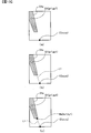
- FIGS. 12A to 12E are diagrams for explaining the processing in steps S601 to S604 in FIG. 12 (a) and 12 (b) are plane conversion images, and FIGS. 12 (c) to 12 (e) are overhead images.
- 12 (a) is the same as FIG. 9 (a)
- FIG. 12 (b) is the same as FIG. 9 (b).
- FIG. 12 (c) is obtained by converting FIG. 12 (a) into an overhead image (step S601)
- FIG. 12 (d) is obtained by converting FIG. 12 (b) into an overhead image (step S602). is there.
- FIG. 12B is an image taken after the time ⁇ t has elapsed from the photographing in FIG. 12A, and the pedestrian X1 has moved to the right side of the figure as compared to FIG. Since the vehicle 10 has moved during the time ⁇ t, the parking frame line Y has also moved when comparing FIG. 12A and FIG. Therefore, also in FIGS. 12 (c) to 12 (d), which are overhead images corresponding to FIGS. 12 (a) to 12 (b), the pedestrian X1a and the parking frame line Ya are moving.
- FIG. 12E is obtained by correcting FIG. 12C based on the amount and direction of movement of the vehicle 10 during the time ⁇ t and calculating the difference between the corrected FIG. 12C and FIG. 12D. (Step S604).
- the parking frame line Ya that has not moved disappears due to the difference calculation, and only the pedestrian difference area X1b that is the difference of the moving pedestrian X1a is shown.
- FIGS. 13A to 13C are diagrams for explaining the process of calculating the closest point Ha from the calculated second candidate region. In FIG.
- the hatched area indicated by the reference numeral X1c is the second candidate area after the pedestrian difference area X1b is subjected to difference grouping (step S605), binarization (step S606), and labeling (step S607). It is an area determined as.
- a camera position C (cx, cy) representing the position of the camera 12 is set in the overhead view image.
- the camera position C is uniquely determined according to the display range of the overhead image.
- the coordinates of the barycentric point G1 of the region X1c representing the moving object are G1 (gx1, gy1).
- a line segment L1 connecting the center of gravity G1 (gx1, gy1) and the camera position C (cx, cy) is set. Furthermore, as shown in FIG.
- the closest point Ha (hx1, hy1) that is the point closest to the camera position C (cx, cy) among the points belonging to the region X1c is obtained.
- the line segment L1 is searched from the center of gravity G1 (gx1, gy1) toward the camera position C (cx, cy), and the end of the region X1c is set as the closest point Ha.
- the closest point Ha (hx1, hy1) searched in this way represents the position of the contact point where the region X1c contacts the road surface.
- the foot position calculation unit 52 performs the following calculation.
- a difference between a plurality of bird's-eye images is calculated, and among the regions having the difference, small regions having a short distance are grouped as a second candidate region.
- the center of gravity of the second candidate region is calculated.
- a coordinate that is included in the second candidate area and that is on the line segment connecting the center of gravity and the camera position on the overhead image and closest to the camera 12 is calculated as the closest point Ha.
- the closest point Hb corresponding to the closest point Ha in the plane conversion image is calculated.
- the coordinates of the center of gravity of the second candidate area and the closest point Ha are registered in the second detection result RES2.
- the closest point Hb on the plane image corresponding to the closest point Ha calculated from the overhead image is also registered in the second detection result RES2.
- step S1301 the first detection result RES1 calculated by the movement vector calculation unit 51 and the second detection result RES2 calculated by the foot position calculation unit 52 are read, and the process proceeds to step S1302.
- step S1302 the initial value 1 is substituted into the loop counter j, and the process proceeds to step S1303.
- step S1311 corresponding to this step the loop counter j is incremented by 1, and the process proceeds again to step S1303. This process is repeated until the loop counter reaches J, which is the total number of records of the first detection result RES1.
- step S1303 the vertex coordinates of the first candidate area in the “j” th record of the first detection result RES1 are read.
- the upper left coordinates of the first candidate area read in this step are referred to as (sxj, syj), and the lower right coordinates are also referred to as (exj, eyj).
- step S1304 the initial value 1 is substituted into the loop counter “m”, and the process proceeds to step S1305.
- step S1305 the coordinates of the closest point Hb in the “m” -th record of the second detection result RES2 are read.
- the coordinates of the closest approach point Hb read in this step are referred to as (hbxm, hbym).
- step S1306 it is determined whether or not the X coordinate of the closest point Hb is included in a predetermined range.
- the predetermined range is a range set by the first candidate area read in step S1303 and a predetermined threshold value TH. More specifically, the X coordinate (horizontal direction) in the planar projection image is a range less than the distance TH from the rectangular area.
- the process proceeds to step S1307, and when it is determined that it is not within the predetermined range, the process proceeds to step S1310.
- step S1307 it is determined whether or not the movement direction of the “j” th record of the first detection result RES1 matches the movement direction of the “m” th record of the second detection result RES2. If it is determined that they are the same, the process proceeds to step S1308, and if it is determined that they are not the same, the process proceeds to step S1310. However, in this specification, it is assumed that not only the coincidence of the movement directions exactly coincides but also the case where the angle formed by the two movement directions is within a predetermined allowable angle.
- step S1308 the upper left coordinate of the integration candidate region having a rectangular shape is registered as (sxj, syj) and the lower right coordinate is registered as (exj, hbym) in the integrated object MOF.
- the integration candidate area includes the Y coordinate of the first candidate area in the “j” th record of the first detection result RES1 and the Y coordinate of the closest point Hb in the “m” th record of the second detection result RES2. It is extended to.
- the process proceeds to step S1309.
- step S1309 the first candidate area and the second candidate area that have been affirmed in step S1307 are deleted. That is, the “j” th record is deleted from the first detection result RES1, and the “m” th record is deleted from the second detection result RES2. Note that the total number of records of the first detection result RES1 and the second detection result RES2 is reduced by this process, but the processes in steps S1302 and S1304 are not affected. This is because the total number of records J in step S1302 and the total number of records M in step S1304 are counted when step S1301 is executed. Next, the process proceeds to step S1310.
- Step S1310 is the loop end of the loop counter “m”. If the loop counter “m” is M, the process proceeds to step S1311, and if the loop counter “m” is not M, the process increments by 1 and returns to step S1305.
- Step S1311 is the loop end of the loop counter j. When the loop counter j is J, the flowchart of FIG. 14 is terminated, and when the loop counter j is not J, it is incremented by 1 and the process returns to step S1303.
- FIG. 15 is a diagram illustrating a processing example of the association unit 53.
- FIG. 15A is a diagram showing three examples of success / failure of association, that is, a diagram showing an example of determination in step S1306 in FIG. 14, and
- FIG. 15B is a diagram showing the first candidate region and the second candidate region. It is a figure showing the example of a process of the relationship between the closest approach point Hb and an integration candidate area
- reference numeral 1350 represents a first candidate area
- reference numerals Hb1 to Hb3 represent three points to be compared with the closest point Hb of the second detection area in the front image.
- the X coordinate of the closest point Hb1 is within the range of the X coordinate of the first candidate region 1350.
- the X coordinate of the closest point Hb2 is outside the range of the X coordinate of the first candidate region 1350, but is within the distance TH from the end of the first candidate region 1350.
- the X coordinate of the closest point Hb3 is outside the range of the X coordinate of the first candidate area 1350 and is separated from the end of the first candidate area 1350 by a distance TH or more.
- the closest points Hb1 and Hb2 are determined to be affirmative in step S1306 of FIG. 14, and the closest point Hb3 is determined to be negative in the same step.
- reference numerals 1351 and Hb4 represent the closest points Hb of the first candidate area and the second candidate area, which have been affirmed in steps S1306 and S1307 in FIG.
- Reference numeral 1352 denotes an integrated region set based on the first candidate region 1351 and the closest point Hb4.
- the X coordinate and the Y coordinate of the integrated area 1352 are displayed slightly shifted to the + side.
- the integrated region 1352 has a shape in which the lower side of the rectangle constituting the first candidate region 1351 is extended downward to the Y coordinate of the closest point Hb4.
- the associating unit 53 performs the following calculation. Based on the first candidate area and the second candidate area, an area for integrating both is calculated. Optical flow, that is, a horizontal distance between the first candidate area calculated based on the movement vector and the closest approach point Hb on the planar image corresponding to the closest approach point Ha of the second candidate area calculated based on the overhead image Is within a predetermined range, and when the movement direction of the first candidate area matches the movement direction of the closest point Hb, the first candidate area and the second candidate area are integrated. That is, the lower end in the vertical direction of the first candidate area is extended to the closest point Hb of the second candidate area, and this area is set as an integrated candidate area.
- This integration candidate area is stored in the integration object MOF.
- step S1401 the tracking mobile body DMO is read from the memory 26, and the integrated object MOF, the first detection result RES1, and the second detection result RES2 are read from the association unit 53, and the process proceeds to step S1402.
- step S1402 the initial value 1 is substituted into the loop counter n, and the process proceeds to step S1403.
- step S1422 the loop counter i is incremented by 1, and the process proceeds again to step S1403.
- step S1403 the initial value 0 is substituted into the counter i, and the process proceeds to step S1404.
- the counter i is used for counting the number of times corresponding to a condition described later.
- step S1404 the initial value 1 is substituted into the loop counter k, and the process proceeds to step S1405 shown in FIG.
- the loop counter k is incremented by 1, and the process proceeds again to step S1405. This process is repeated until the loop counter reaches K which is the total number of records of the integrated object MOF.
- step S1405 of FIG. 17 is the integrated candidate area recorded in the “k” th record in the integrated object MOF at the predicted position of the mobile body recorded in the “n” th record in the tracking mobile body DMO? Judge whether or not. In other words, it is determined whether or not the predicted position of the “n” th record in the tracking mobile body DMO includes the coordinates of the “k” th record in the integrated object MOF. If it is determined that it is included, the process proceeds to step S1406. If it is determined that it is not included, the process proceeds to step S1408. Note that the predicted position of the mobile object read in this step is calculated in step S1423 described later when the tracking processing unit 55 is executed immediately before.
- step S1406 it is determined whether or not the moving direction of the “n” th record in the tracking mobile body DMO matches the moving direction of the “k” th record in the integrated object MOF. If it is determined that they match, the process proceeds to step S1407, and if it does not match, the process proceeds to step S1416 in FIG.
- step S1407 the update position, movement direction, and tracking certainty factor of the “n” th record in the tracking mobile body DMO are changed as follows. That is, the coordinates of the “k” -th record in the integrated object MOF are substituted for the update position, the movement direction of the “k” -th record in the integrated object MOF is substituted for the movement direction, and the tracking confidence is greatly increased. Increase by 20. Next, the process proceeds to step S1416 in FIG.
- step S1408 which is executed when a negative determination is made in step S1405, the first candidate area of the first detection result RES1 exists at the predicted position of the mobile body recorded in the “n” -th record in the tracking mobile body DMO. Determine whether or not. In other words, it is determined whether or not the coordinates of any of the first candidate areas are included in the predicted position of the “n” th record in the tracking mobile body DMO. If it is determined that any of the first candidate areas is included, the process proceeds to step S1409, and if it is determined that no included first candidate area exists, the process proceeds to step S1411.
- the first candidate area determined to include coordinates at the predicted position in this step is referred to as a specific first candidate area.
- step S1409 it is determined whether the moving direction of the “n” -th record in the tracking mobile body DMO matches the moving direction of the specific first candidate area. If it is determined that the movement directions match, the process proceeds to step S1410. If it is determined that the movement directions do not match, the process proceeds to step S1416 in FIG.
- step S1410 the update position, movement direction, and tracking certainty factor of the “n” th record in the tracking mobile body DMO are changed as follows. That is, the predicted position of the moving body of the same record is substituted for the update position, the movement direction of the specific first candidate region is substituted for the movement direction, and the tracking certainty is decreased, for example, 10 is decreased. Next, the process proceeds to step S1416 in FIG.
- step S1411 which is executed when a negative determination is made in step S1408, the closest point Hb of the second detection result RES2 exists at the predicted position of the mobile body recorded in the “n” -th record in the tracking mobile body DMO. Determine whether or not. In other words, it is determined whether the predicted position of the “n” -th record in the tracking mobile body DMO includes the closest point Hb of any second detection result RES2. If it is determined that any of the closest points Hb is included, the process proceeds to step S1412. If it is determined that the included closest point Hb does not exist, the process proceeds to step S1415.
- the second candidate area determined to include the closest point Hb at the predicted position in this step is referred to as a specific second candidate area.
- step S1412 it is determined whether the movement direction of the “n” -th record in the tracking mobile body DMO matches the movement direction of the specific second candidate area. If it is determined that the movement directions match, the process proceeds to step S1413. If it is determined that the movement directions do not match, the process proceeds to step S1414. In step S1413, the update position and moving direction of the “n” -th record in the tracking mobile body DMO are changed as follows. That is, the coordinate of the closest approach point Hb of the specific second candidate area is substituted for the update position, and the movement direction of the specific second candidate area is substituted for the movement direction. Next, the process proceeds to step S1416 in FIG.
- step S1414 the update position of the “n” -th record in the tracking mobile DMO and the tracking certainty are changed as follows. That is, the coordinates of the closest approach point Hb of the specific second candidate region are substituted into the update position, and the tracking certainty is slightly decreased, for example, decreased by 5.
- step S1416 the process proceeds to step S1416 in FIG.
- step S1415 which is executed when a negative determination is made in steps S1405, S1408, and S1411, the counter i is incremented, that is, i is incremented by 1, and the process proceeds to step S1416 in FIG.
- Step S1416 in FIG. 18 is the loop end of the loop counter k. If the loop counter k is K, the process proceeds to step S1417. If the loop counter k is not K, the loop counter k is incremented by 1 and the step in FIG. The process returns to S1405. In step S1417, it is determined whether or not the counter i is equal to K which is the total number of records of the integrated object MOF. If it is determined that it is equal to K, the process proceeds to step S1418. If it is determined that it is not equal to K, the process proceeds to step S1419.
- step S1418 the tracking certainty factor of the “n” -th record in the tracking mobile body DMO is greatly reduced, for example, 20 and the predicted position of the mobile body of the same record is substituted for the update position.
- step S1419 the process proceeds to step S1419.
- step S1419 it is determined whether the tracking certainty factor of the “n” -th record in the tracking mobile body DMO is a disappearance threshold, for example, zero or more. If it is determined that the threshold value is equal to or greater than the disappearance threshold value, the process proceeds to step S1420. If it is determined that the threshold value is less than the disappearance threshold value, the process proceeds to step S1421. In step S1420, it is determined not to delete the “n” -th record of the tracking mobile body DMO, and the update position, the movement direction, and the speed, which are the positions of the specified mobile body, which are information of the record, are used as the mobile body information. Output to the route generation unit 17. Next, the process proceeds to step S1422. In step S1421, the “n” -th record in the tracking mobile body DMO is deleted, and the process proceeds to step S1422.
- a disappearance threshold for example, zero or more.
- Step S1422 is the loop end of the loop counter n. If the loop counter n is N, the process proceeds to step S1423. If the loop counter n is not N, the loop counter n is incremented by 1, and the process returns to step S1403 in FIG. . In step S1423, a new predicted position is calculated based on the speed, moving direction, and update position of each record for all the records of the tracking mobile DMO. The calculated predicted position is recorded in the tracking mobile unit DMO, and the update position of each record is cleared, that is, deleted, and the program represented by the flowcharts of FIGS. 16 to 18 is terminated.
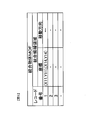
- FIG. 19 shows the update position, moving direction, and tracking certainty factor of the tracking mobile body DMO by the operation of the tracking processing unit 55 described with reference to FIGS.
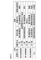
- FIG. 19 is a list showing update processing of the tracking mobile body DMO by the tracking processing unit 55.
- FIG. 19 shows that a corresponding process is performed when a predetermined condition is met.
- “Coordinate match” in the “Condition” column means that the predicted position of the record having the tracking mobile DMO matches the coordinates of the integration candidate region, the first candidate region, and the second candidate region, or does not match any of them. It shows that.
- “Movement direction” in the “Condition” column indicates whether the movement direction of the record having the tracking mobile body DMO matches the movement direction of the integrated candidate region, the first candidate region, or the second candidate region having the same coordinates.
- “Update position”, “movement direction”, and “tracking certainty” in the “process” column indicate update processing of each value of the moving object candidate area of the record having the tracking moving object DMO.
- the tracking processing unit 55 performs the following calculation.
- the tracking processing unit 55 reads the integrated object MOF, the first detection result RES1, the first detection result RES1, and the tracking mobile body DMO.
- the tracking processing unit 55 updates the position of the mobile body stored in the tracking mobile body DMO, that is, specifies the position of the mobile body, deletes the mobile body from the tracking target, that is, deletes a specific record from the tracking mobile body DMO. , Outputting information related to the moving object to the route generation unit 17 and changing the tracking certainty.
- the tracking certainty becomes equal to or lower than a predetermined value, the tracking certainty is deleted from the tracking mobile body DMO.
- step S1501 the moving object candidate CPE is read from the memory 26, and the integrated object MOF, the first detection result RES1, and the second detection result RES2 are read from the tracking moving object DMO, and the process proceeds to step S1502.
- step S1502 the initial value 1 is substituted into the loop counter n, and the process proceeds to step S1503.
- step S1525 the loop counter i is incremented by 1, and the process again proceeds to step S1503.
- N the total number of records of the moving object candidate CPE.
- step S1503 the initial value 0 is substituted into the counter i, and the process proceeds to step S1504.
- step S1504 the initial value 1 is substituted into the loop counter k, and the process proceeds to step S1505 shown in FIG.
- the loop counter k is incremented by 1, and the process again proceeds to step S1505. This process is repeated until the loop counter reaches K which is the total number of records of the integrated object MOF.
- step S1505 in FIG. 21 is the integrated candidate area recorded in the “k” th record in the integrated object MOF at the predicted position of the moving object recorded in the “n” th record in the moving object candidate CPE? Judge whether or not. In other words, it is determined whether the coordinates of the “k” th record in the integrated object MOF are included in any predicted position of the “n” th record in the moving object candidate CPE. If it is determined that it is included, the process proceeds to step S1506, and if it is determined that it is not included, the process proceeds to step S1509. Note that the predicted position of the moving body read in this step is calculated in step S1528 described later when the tracking moving body determining unit 54 is executed immediately before.
- step S1506 it is determined whether or not the movement direction of the “n” th record in the moving object candidate CPE matches the movement direction of the “k” th record in the integrated object MOF. If it is determined that they match, the process proceeds to step S1507. If it is determined that they do not match, the process proceeds to step S1508.
- step S1507 the update position, moving direction, and moving object certainty factor of the “n” th record in the moving object candidate CPE are changed as follows. That is, the coordinates of the “k” -th record in the integrated object MOF are substituted into the update position, the movement direction of the “k” -th record in the integrated object MOF is substituted into the movement direction, and the moving object reliability is increased, for example, 10 increase. Next, the process proceeds to step S1517 in FIG.
- step S1508 the “k” th record in the integrated object MOF is registered as a new record of the moving object candidate CPE.
- the moving object certainty factor is set to a predetermined value, for example, 50.
- the predicted position of the added record is blank, and the update position of the added record is the coordinate of the “k” th record in the integrated object MOF.
- the predicted position is calculated by a process described later.
- the process proceeds to step S1517 in FIG.
- step S1509 which is executed when a negative determination is made in step S1505, the first candidate region of the first detection result RES1 exists at any predicted position recorded in the “n” -th record in the moving object candidate CPE. Determine whether or not. In other words, it is determined whether or not the coordinates of any of the first candidate areas are included in any of the predicted positions of the “n” th record in the moving object candidate CPE. If it is determined that any of the first candidate areas is included, the process proceeds to step S1510. If it is determined that no included first candidate area exists, the process proceeds to step S1512. In the following description of the operation of the tracking mobile body determination unit 54, the first candidate area determined to include coordinates at the predicted position in this step is referred to as a specific first candidate area.
- step S1510 it is determined whether the moving direction of the “n” th record in the moving object candidate CPE matches the moving direction of the specific first candidate area. If it is determined that the movement directions match, the process proceeds to step S1511. If it is determined that the movement directions do not match, the process proceeds to step S1517 in FIG.
- step S1511 the update position, moving direction, and moving object certainty factor of the “n” th record in the moving object candidate CPE are changed as follows. That is, the predicted position of the “n” th record in the moving object candidate CPE is substituted for the update position, the moving direction of the specific first candidate region is substituted for the moving direction, and the moving object certainty factor is decreased, for example, 10 is decreased. However, the predicted position to be substituted for the update position is the predicted position having the shortest distance from the specific first candidate region among the plurality of predicted positions stored in the record. Next, the process proceeds to step S1517 in FIG.
- step S1512 executed when a negative determination is made in step S1509, the closest point Hb of the second detection result RES2 exists at the predicted position of the moving object recorded in the “n” -th record in the moving object candidate CPE. Determine whether or not. In other words, it is determined whether the predicted position of the “n” th record in the moving object candidate CPE includes the closest point Hb of any second detection result RES2. If it is determined that any of the closest points Hb is included, the process proceeds to step S1513. If it is determined that the included closest point Hb does not exist, the process proceeds to step S1516.
- the second candidate area determined to include the closest point Hb in the predicted position in this step is referred to as a specific second candidate area.
- step S1513 it is determined whether the moving direction of the “n” th record in the moving object candidate CPE matches the moving direction of the specific second candidate area. If it is determined that the moving directions match, the process proceeds to step S1514. If it is determined that the moving directions do not match, the process proceeds to step S1515.
- step S1514 the update position, the moving direction, and the moving object certainty factor of the “n” th record in the moving object candidate CPE are changed as follows. That is, the coordinate of the closest approach point Hb of the specific second candidate region is substituted for the update position, the movement direction of the specific second candidate region is substituted for the movement direction, and the moving object reliability is slightly decreased, for example, decreased by five. Next, the process proceeds to step S1517 in FIG.
- step S1515 the update position of the “n” -th record in the moving object candidate CPE and the moving object certainty factor are changed as follows. That is, the coordinate of the closest approach point Hb of the specific second candidate region is substituted into the update position, and the moving object certainty factor is slightly reduced, for example, five.
- step S1517 in FIG. In step S1516, which is executed when a negative determination is made in steps S1505, S1509, and S1512, the counter i is incremented, that is, i is incremented by 1, and the process proceeds to step S1517 in FIG.
- Step S1517 in FIG. 22 is the loop end of the loop counter k. If the loop counter k is K, the process proceeds to step S1518. If the loop counter k is not K, the loop counter k is incremented by 1 and the step in FIG. The process returns to S1505.
- step S1518 it is determined whether or not the counter i is equal to K which is the total number of records of the integrated object MOF. If it is determined that it is equal to K, the process proceeds to step S1519. If it is determined that it is not equal to K, the process proceeds to step S1520.
- step S1519 the moving object certainty factor of the “n” -th record in the moving object candidate CPE is greatly reduced, for example, 20 and the predicted position of the moving object candidate area of the same record is substituted for the update position. Note that the moving object candidate region has a plurality of candidates for predicted positions, and among them, the predicted position with the shortest distance is substituted for the updated position. Next, the process proceeds to step S1520.
- step S1520 it is determined whether the moving object certainty factor of the “n” -th record in the moving object candidate CPE is a tracking threshold, for example, 100 or more. If it is determined that the value is equal to or greater than the tracking threshold value, the process proceeds to step S1521, and if it is determined that the value is less than the tracking threshold value, the process proceeds to step S1522.
- step S1521 the “n” th record in the moving object candidate CPE is registered as a new record of the tracking moving object DMO. At this time, the tracking reliability is set to a predetermined value, for example, 50.
- the predicted position of the record to be added is blank, and the predicted position of the “n” th record in the moving object candidate CPE is set as the update position of the added record. The predicted position of the added record is calculated by a process described later. Next, the process proceeds to step S1525.
- step S1522 it is determined whether or not the moving object certainty of the “n” th record in the moving object candidate CPE is greater than or equal to a disappearance threshold, for example, zero. If it is determined that the value is greater than or equal to the disappearance threshold, the process proceeds to step S1525. If it is determined that the value is less than the disappearance threshold, the process proceeds to step S1524. In step S1524, the “n” -th record in the moving object candidate CPE is deleted, and the process proceeds to step S1525. Step S1525 is the loop end of the loop counter n. If the loop counter n is N, the process proceeds to step S1526. If the loop counter n is not N, the loop counter n is incremented by 1, and the process returns to step S1503 in FIG. .
- a disappearance threshold for example, zero.
- step S1526 it is determined whether there is an integrated object MOF that does not belong to any moving object candidate CPE. In other words, whether or not there is a record of the integrated object MOF in which step S1505 is not affirmatively determined (hereinafter referred to as “all negative determination record”) for any of the records 1 to N of the moving object candidate CPE. to decide. If it is determined that there is an all-negative determination record, the process proceeds to step S1527. If it is determined that no all-negative determination record exists, the process proceeds to step S1528.
- step S1527 the all negative determination record is registered as a new record of the moving object candidate CPE.
- the moving object certainty factor is set to a predetermined value, for example, 50.
- the predicted position of the added record is blank, and the update position of the added record is the coordinate of the all negative determination record.
- step S1528 for all the records of the moving object candidate CPE, a plurality of new predicted positions are calculated based on the moving direction and update position of each record and a plurality of predetermined speeds.
- the plurality of predetermined speeds are speeds corresponding to, for example, walking, small running, and full speed running.
- the calculated predicted position is recorded in each record of the moving object candidate CPE, and the update position of each record is cleared, that is, deleted, and the program represented by the flowcharts of FIGS. 20 to 22 is terminated.
- FIG. 23 shows the update of the moving object candidate CPE, the moving direction, and the moving object certainty factor by the operation of the tracking moving object determining unit 54 described with reference to FIGS.
- FIG. 23 is a list showing the update process of the moving object candidate CPE by the tracking moving object determining unit 54.
- FIG. 23 shows that corresponding processing is performed when a predetermined condition is met.
- “Coordinate match” in the “Condition” column means that the predicted position of the moving object candidate area recorded in the record having the moving object candidate CPE matches the coordinates of the integration candidate area, the first candidate area, and the second candidate area. Indicates that it does or does not match either.
- “Movement direction” in the “Condition” column indicates whether or not the movement direction of the record having the moving object candidate CPE matches the movement direction of the integrated candidate area, the first candidate area, or the second candidate area having the same coordinates.
- Indicate. “Update position”, “moving direction”, and “moving object certainty factor” in the “Processing” column indicate update processing of each value of the moving object candidate area of the record having the moving object candidate CPE. However, if the coordinates match the integration candidate area and the movement direction does not match, the integration candidate area is added to the tracking mobile body DMO.
- the tracking mobile body determination unit 54 performs the following calculation.
- the tracking mobile body determination unit 54 reads the integrated object MOF, the first detection result RES1, the second detection result RES2, and the mobile body candidate CPE.
- the tracking mobile body determination unit 54 adds or deletes records from the mobile body candidate CPE, adds records that satisfy the criteria described later to the tracking mobile body DMO, and increases or decreases the mobile body reliability described later.
- the mobile object reliability becomes 0 or less, the record is deleted from the mobile object candidate CPE.
- the mobile object reliability exceeds 100 the record is moved from the mobile object candidate CPE to the tracking mobile object DMO.
- the tracking device includes a movement vector calculation unit 51 that calculates a first candidate region from a captured image, a foot position calculation unit 52 that calculates a second candidate region from an overhead image, a first candidate region, An associating unit 53 that calculates an integrated candidate region associated with the second candidate region, a tracking processing unit 55 that tracks a mobile object that is a tracking target based on the first and second candidate regions, and the integrated candidate region; And a tracking mobile body determination unit 54 that determines a mobile body to be tracked. Each time a captured image is input, a first candidate area, a second candidate area, and an integrated candidate area are calculated.
- the moving object candidate CPE and the tracking moving object DMO are stored in the memory 26 and updated by the tracking moving object determining unit 54 and the tracking processing unit 55 every time a captured image is input.
- the route generation unit 17 calculates the movement route of the vehicle 10 based on the moving body information output from the tracking processing unit 55.
- the calculated movement route is displayed on the monitor 34 via the display control unit 32.
- the vehicle behavior control ECU 30 may prevent the collision by controlling the brake actuator 36 based on the output of the route generation unit 17.
- the moving body information output from the tracking processing unit 55 includes the position, moving direction, and speed of the moving body.
- the route generation unit 17 calculates a movement route that avoids a collision with a moving body, but outputs a stop instruction to the display control unit 32 when a movement route that can avoid the collision cannot be calculated.
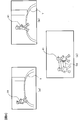
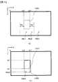
- FIG. 24 is a diagram illustrating a state in which the route generation unit 17 generates a route based on the moving body information output from the tracking processing unit 55.
- 24A and 24B are common in that the moving body 70 exists in the front left of the vehicle 10 and the moving body 71 exists in the front right of the vehicle 10.
- the moving body 70 located on the left front side of the vehicle 10 moves to the left side in the figure
- the moving body 71 located on the right front side of the vehicle 10 moves to the right side in the figure.
- the path generation unit 17 that has received the mobile body information from the tracking processing unit 55 generates a path 72 that travels between the mobile body 70 and the mobile body 71, that is, travels substantially straight.
- the moving body 70 located on the left front side of the vehicle 10 and the moving body 71 located on the right front side of the vehicle 10 move to the left side in the figure.
- the path generation unit 17 that has received the moving body information from the tracking processing unit 55 generates a path 73 that swells to the right in the figure so as to go around between the moving body 70 and the moving body 71.
- the tracking device that is, the image processing ECU 18 includes an imaging unit, that is, an image input unit to which an image obtained by the camera 12 is input, that is, a communication unit 18a, and a plurality of images input to the image input unit. Is generated based on a plurality of images, and a first moving body detection unit that detects the position and moving direction of the moving body based on the calculated optical flow, and a moving vector calculation unit 51 Integrates the detection results of the second moving body detecting unit that detects the position and moving direction of the moving body based on a plurality of overhead images, that is, the foot position calculating unit 52, and the first moving body detecting unit and the second moving body detecting unit.
- a third moving body detection unit for detecting the position and moving direction of the moving body, that is, the associating unit 53, and the moving body to be tracked based on the detection results of the first to third moving body detection units.
- the tracking mobile body determination unit 54 to be determined, the estimation unit 55a for estimating the future position and moving direction of the tracking mobile body determined by the tracking mobile body determination unit 54, and the first to third mobile body detection units.
- a tracking unit 55b that tracks the tracking mobile body using any one of the positions of the mobile bodies and the estimated position estimated by the estimation unit 55a and identifies the position of the tracking mobile body.
- the image processing ECU 18 Since the image processing ECU 18 is configured as described above, it is impossible to detect the first candidate region using the optical flow by the movement vector calculation unit 51 or to detect the second candidate region using the overhead image by the foot position calculation unit 52. Even in such a case, since tracking of the moving body can be continued by the tracking processing unit 55, it is easy to continue tracking of the moving body.
- the second moving body detection unit that is, the foot position calculation unit 52 calculates the difference area that is the difference between the plurality of overhead images and the centroid G of the difference area, is included in the difference area, and is the centroid G of the difference area.
- a point closest to the position C of the image pickup unit that is, the closest point on the line segment L1 connecting the image pickup unit position C in the bird's-eye view image as a moving object. Therefore, it is possible to accurately detect the foot position of the moving body that is difficult to calculate with the optical flow.
- the third moving body detecting unit that is, the associating unit 53 is a horizontal line between the position of the moving body detected by the first moving body detecting unit and the position of the moving body detected by the second moving body detecting unit.
- the moving body detected by the first moving body detection unit and the moving body detected by the second moving body detection unit are integrated.
- the detection result of the moving object by the optical flow that is easy to detect the moving object and has high horizontal accuracy and the detection result of the moving object by the bird's-eye view image with high detection accuracy of the foot position are divided into two conditions: the position and the moving direction. Can be integrated with high accuracy.
- the position of the moving body detected by the first moving body detecting unit, that is, the moving vector calculating unit 51, and the third moving body detecting unit, that is, the associating unit 53, is an area that extends in the horizontal and vertical directions. is there.
- the third moving body detection unit extends the lower end in the vertical direction of the area of the moving body detected by the first moving body detection unit to be integrated to the lower end in the vertical direction of the moving body detected by the second moving body detection unit to be integrated. This area is set as the position of the moving body detected by the third moving body detection unit. For this reason, the region detected by the movement vector calculation unit 51 with high horizontal accuracy is expanded to the closest point Hb calculated by the foot position calculation unit 52 with high foot position accuracy. I can grasp it well.
- the tracking mobile body determination unit 54 stores the mobile body reliability, which is an index indicating the probability of determining the mobile body candidate that is the tracking mobile body candidate as the tracking target, and determines the future position of the mobile body candidate. presume.
- the tracking mobile body determination unit 54 further includes the future position of the mobile body candidate estimated by the tracking mobile body determination unit 54, the position of the mobile body detected by the third mobile body detection unit, and the first mobile body detection unit.
- the mobile object reliability is increased or decreased based on the relationship between the position of the mobile object detected by the mobile object and the position of the mobile object detected by the second mobile object detection unit.
- a candidate is determined as a new tracking mobile. Therefore, when the moving object certainty factor of the moving object candidate area is equal to or greater than a predetermined threshold value, the moving object candidate area is determined as a new moving object to be tracked by the tracking processing unit 55. Can be newly targeted for tracking.
- the distance between the future position of the tracking mobile body estimated by the estimation unit 55a and the position of the mobile body detected by the third mobile body detection unit is less than a predetermined distance.
- the future moving direction of the tracking moving body estimated by the estimating unit 55a matches the moving direction of the moving body detected by the third moving body detecting unit, the moving body detected by the third moving body detecting unit is detected.
- the position of the mobile body be the tracked position of the tracking mobile body.
- the distance between the future position of the tracking mobile body estimated by the estimation unit 55a and the position of the mobile body detected by the third mobile body detection unit is equal to or greater than a predetermined distance, and the estimation unit 55a
- the distance between the estimated future position of the tracking mobile object and the position of the mobile object detected by the first mobile object detection unit is less than a predetermined distance, and the future of the tracking mobile object estimated by the estimation unit 55a
- the estimated position estimated by the estimating unit 55a is set as the tracked position of the tracking moving body.
- the distance between the future position of the tracking mobile body estimated by the estimation unit 55a and the position of the mobile body detected by the third mobile body detection unit is equal to or greater than a predetermined distance
- the estimation unit 55a The distance between the estimated future position of the tracking mobile body and the position of the mobile body detected by the first mobile body detection unit is a predetermined distance or more, and the future of the tracking mobile body estimated by the estimation unit 55a
- the position of the moving body detected by the second moving body detection unit is tracked by the moving body. Position.
- the moving object can be tracked by comparing the direction.
- the tracking unit 55b stores a tracking certainty factor that is an index indicating the likelihood of tracking the tracking mobile unit for each of the tracking mobile units, the future position of the tracking mobile unit estimated by the estimation unit, 3. Tracking based on the relationship between the position of the moving body detected by the moving body detection unit, the position of the moving body detected by the first moving body detection unit, and the position of the moving body detected by the second moving body detection unit.
- the certainty factor is increased or decreased and the tracking certainty factor becomes a predetermined value or less, the tracking moving body is excluded from the tracking target. Therefore, the tracking certainty is increased or decreased together with the tracking process for updating the position of the moving object, and when the tracking certainty falls below a predetermined threshold, the moving object is excluded from the tracking target. Processing load to be reduced. In addition, it is possible to ensure a certainty of tracking with respect to the moving object tracked by the tracking processing unit 55.
- the tracking processing unit 55 assumes the movement of the moving body as a constant velocity motion, and stores the speed of the moving body in the tracking moving body DMO.
- the tracking processing unit 55 may calculate the movement of the moving body using a Kalman filter and store the parameter in the tracking moving body DMO. According to the first modification, it is possible to accurately estimate the movement of the moving body.
Abstract
A tracking device equipped with: an image input unit to which images obtained by imaging with an imaging unit are input; a first moving body detection unit that calculates an optical flow using multiple images that have been input to the image input unit, and that detects the position and direction of movement of a moving body on the basis of the calculated optical flow; a second moving body detection unit that detects the position and direction of movement of a moving body on the basis of multiple overhead images generated on the basis of the multiple images; a third moving body detection unit that detects the position and direction of movement of the moving body by integrating the detection results from the first moving body detection unit and the second moving body detection unit; a tracked moving body confirmation unit that determines a moving body that should be tracked, on the basis of the detection results from the first through third moving body detection units; an estimation unit that estimates a future position and direction of movement of the tracked moving body determined by the tracked moving body confirmation unit; and a tracking unit that tracks the tracked moving body and identifies the position of the tracked moving body, by using any one of the following: the position of the respective moving bodies detected by the second and third moving body detection units; and the estimated position estimated by the estimation unit.
Description
本発明は、追跡装置に関する。
The present invention relates to a tracking device.
近年、カメラやソナーなどの外界センサを車両に設置し、車両の周囲に存在する移動体を検出してドライバに対する警告や車両制御を実施することで、運転者をサポートする運転支援機能、自動運転技術の開発が急速に進んでいる。移動体の検出においては、検出の確からしさを向上させるために、異なる時刻に得られた情報を用いて移動体の位置を追跡することが有効である。
特許文献1には、過去の撮像画像から求められた対象物の路面上の位置、及び車両運動情報に基づいて、現在の対象物の路面上での位置を予測して、対応する現在の撮像画像上の位置に検出枠を設定することで対象物を検出し、設定した検出枠内の画像の足元位置に基づいて、対象物の現在位置を推定し、過去の撮像画像における対象物に対する現在の撮像画像における対象物の拡大率に基づいて、対象物の路面上の現在位置を推定する対象物追跡装置が開示されている。 In recent years, external sensors such as cameras and sonar have been installed in vehicles to detect moving objects in the vicinity of the vehicle and perform driver warnings and vehicle control to support drivers and automatic driving. Technology development is progressing rapidly. In detecting a moving object, it is effective to track the position of the moving object using information obtained at different times in order to improve the probability of detection.
InPatent Document 1, the current position of the target object on the road surface is predicted based on the position of the target object on the road surface obtained from the past captured image and the vehicle motion information, and the corresponding current image pickup is performed. An object is detected by setting a detection frame at a position on the image, the current position of the object is estimated based on the foot position of the image within the set detection frame, and the current position relative to the object in the past captured image is estimated. An object tracking device that estimates the current position of a target object on a road surface based on the magnification ratio of the target object in the captured image is disclosed.
特許文献1には、過去の撮像画像から求められた対象物の路面上の位置、及び車両運動情報に基づいて、現在の対象物の路面上での位置を予測して、対応する現在の撮像画像上の位置に検出枠を設定することで対象物を検出し、設定した検出枠内の画像の足元位置に基づいて、対象物の現在位置を推定し、過去の撮像画像における対象物に対する現在の撮像画像における対象物の拡大率に基づいて、対象物の路面上の現在位置を推定する対象物追跡装置が開示されている。 In recent years, external sensors such as cameras and sonar have been installed in vehicles to detect moving objects in the vicinity of the vehicle and perform driver warnings and vehicle control to support drivers and automatic driving. Technology development is progressing rapidly. In detecting a moving object, it is effective to track the position of the moving object using information obtained at different times in order to improve the probability of detection.
In
移動体の追跡を継続することが望まれている。
It is hoped that tracking of moving objects will continue.
本発明の第1の態様によると、追跡装置は、撮像部が撮影して得られた画像が入力される画像入力部と、画像入力部に入力された複数の画像を用いてオプティカルフローを算出し、算出したオプティカルフローに基づいて移動体の位置および移動方向を検出する第1移動体検出部と、複数の画像に基づいて生成された複数の俯瞰画像に基づいて移動体の位置および移動方向を検出する第2移動体検出部と、第1移動体検出部および第2移動体検出部の検出結果を統合し移動体の位置および移動方向を検出する第3移動体検出部と、第1~第3移動体検出部の検出結果に基づいて追跡すべき移動体を決定する追跡移動体確定部と、追跡移動体確定部が決定した追跡移動体の将来の位置および移動方向を推定する推定部と、第2~第3移動体検出部でそれぞれ検出された移動体それぞれの位置、および、推定部で推定された推定位置のいずれか一つを用いて追跡移動体を追跡し当該追跡移動体の位置を特定する追跡部とを備える。
According to the first aspect of the present invention, the tracking device calculates an optical flow using an image input unit to which an image obtained by photographing by an imaging unit is input, and a plurality of images input to the image input unit. A first moving body detecting unit that detects the position and moving direction of the moving body based on the calculated optical flow, and a position and moving direction of the moving body based on the plurality of overhead images generated based on the plurality of images. A second moving body detector that detects the position of the moving body and a moving direction by integrating the detection results of the first moving body detector and the second moving body detector; A tracking moving body determination unit that determines a moving body to be tracked based on a detection result of the third moving body detection unit, and an estimation that estimates a future position and a moving direction of the tracking mobile body determined by the tracking mobile body determination unit And second to third moving body tests A tracking unit that tracks the tracking mobile body using any one of the positions of the respective mobile bodies detected by the unit and the estimated position estimated by the estimation unit and identifies the position of the tracking mobile body .
本発明によれば、オプティカルフローを用いた移動体の検出、または俯瞰画像を用いた移動体の検出が不可能な場合であっても移動体の追跡を継続できる。
According to the present invention, tracking of a moving object can be continued even when detection of a moving object using an optical flow or detection of a moving object using an overhead image is impossible.
(第1の実施の形態)
以下、図1~図24を参照して、本発明にかかる移動体検出装置を画像処理ECUに適用した第1の実施の形態を説明する。
図1は、画像処理ECU18を搭載する車両10の構成を示す図である。車両10は、車両10の移動量を算出するための車輪速センサ20と、車両10の進行方向を算出するための操舵角センサ22と、車輪速センサ20および操舵角センサ22の出力を後述する画像処理ECU18に送信するセンサインタフェース24と、車両10の周囲を撮影するカメラ12と、カメラ12が撮影して得られた画像を画像処理ECU18に送信するカメラインタフェース14と、車両10の移動経路を算出する経路生成部17と、カメラ12が撮影して得られた画像を用いて車両10の周囲に存在する移動体を検出する画像処理ECU18と、画像処理ECU18が一時的な記憶部として使用する揮発性の記憶領域であるメモリ26と、車両10のユーザに情報を提示するモニタ34と、モニタ34を制御する表示制御部32と、車両10に制動力を生じさせるブレーキアクチュエータ36と、ブレーキアクチュエータ36に動作指令を出力する車両挙動制御ECU30とを備える。 (First embodiment)
Hereinafter, a first embodiment in which a moving body detection apparatus according to the present invention is applied to an image processing ECU will be described with reference to FIGS.
FIG. 1 is a diagram illustrating a configuration of a vehicle 10 on which theimage processing ECU 18 is mounted. The vehicle 10 will be described later with the wheel speed sensor 20 for calculating the amount of movement of the vehicle 10, the steering angle sensor 22 for calculating the traveling direction of the vehicle 10, and the outputs of the wheel speed sensor 20 and the steering angle sensor 22. A sensor interface 24 that transmits to the image processing ECU 18, a camera 12 that captures the surroundings of the vehicle 10, a camera interface 14 that transmits images obtained by the camera 12 to the image processing ECU 18, and a moving path of the vehicle 10. The path generation unit 17 to be calculated, the image processing ECU 18 that detects a moving body existing around the vehicle 10 using the image obtained by the camera 12, and the image processing ECU 18 uses as a temporary storage unit. A memory 26 that is a volatile storage area, a monitor 34 that presents information to the user of the vehicle 10, and a display control unit 3 that controls the monitor 34 When provided with a brake actuator 36 to generate a braking force to the vehicle 10, a vehicle behavior control ECU30 outputs the operation command to the brake actuator 36.
以下、図1~図24を参照して、本発明にかかる移動体検出装置を画像処理ECUに適用した第1の実施の形態を説明する。
図1は、画像処理ECU18を搭載する車両10の構成を示す図である。車両10は、車両10の移動量を算出するための車輪速センサ20と、車両10の進行方向を算出するための操舵角センサ22と、車輪速センサ20および操舵角センサ22の出力を後述する画像処理ECU18に送信するセンサインタフェース24と、車両10の周囲を撮影するカメラ12と、カメラ12が撮影して得られた画像を画像処理ECU18に送信するカメラインタフェース14と、車両10の移動経路を算出する経路生成部17と、カメラ12が撮影して得られた画像を用いて車両10の周囲に存在する移動体を検出する画像処理ECU18と、画像処理ECU18が一時的な記憶部として使用する揮発性の記憶領域であるメモリ26と、車両10のユーザに情報を提示するモニタ34と、モニタ34を制御する表示制御部32と、車両10に制動力を生じさせるブレーキアクチュエータ36と、ブレーキアクチュエータ36に動作指令を出力する車両挙動制御ECU30とを備える。 (First embodiment)
Hereinafter, a first embodiment in which a moving body detection apparatus according to the present invention is applied to an image processing ECU will be described with reference to FIGS.
FIG. 1 is a diagram illustrating a configuration of a vehicle 10 on which the
センサインタフェース24と、カメラインタフェース14と、経路生成部17と、画像処理ECU18と、表示制御部32と、車両挙動制御ECU30とは、システムバス16により接続されている。
カメラ12は、予め定めた時間Δtごと、たとえば17ミリ秒ごとに撮影を行い、撮影により得られた情報をカメラインタフェース14に出力する。カメラインタフェース14は、カメラ12から受信した情報を用いて、カメラ12に装着されたレンズの収差を考慮した補正を施したうえで画像を作成し、画像処理ECU18に送信する。したがって、カメラ12が撮影を行うごとにカメラインタフェース14から画像処理ECU18へ作成した画像が出力される。以下では、カメラインタフェース14が画像処理ECU18へ出力する画像を「撮影画像」と呼ぶ。 Thesensor interface 24, the camera interface 14, the route generation unit 17, the image processing ECU 18, the display control unit 32, and the vehicle behavior control ECU 30 are connected by a system bus 16.
Thecamera 12 shoots every predetermined time Δt, for example, every 17 milliseconds, and outputs information obtained by the shooting to the camera interface 14. The camera interface 14 uses the information received from the camera 12, performs correction in consideration of the aberration of the lens attached to the camera 12, creates an image, and transmits the image to the image processing ECU 18. Therefore, every time the camera 12 performs photographing, the created image is output from the camera interface 14 to the image processing ECU 18. Hereinafter, an image output from the camera interface 14 to the image processing ECU 18 is referred to as a “captured image”.
カメラ12は、予め定めた時間Δtごと、たとえば17ミリ秒ごとに撮影を行い、撮影により得られた情報をカメラインタフェース14に出力する。カメラインタフェース14は、カメラ12から受信した情報を用いて、カメラ12に装着されたレンズの収差を考慮した補正を施したうえで画像を作成し、画像処理ECU18に送信する。したがって、カメラ12が撮影を行うごとにカメラインタフェース14から画像処理ECU18へ作成した画像が出力される。以下では、カメラインタフェース14が画像処理ECU18へ出力する画像を「撮影画像」と呼ぶ。 The
The
画像処理ECU18は、通信部18a、CPU、ROM、およびRAMを備え、ROMに保存されたプログラムをRAMに展開して実行する。通信部18aは、システムバス16を経由してカメラインタフェース14と通信を行い、カメラ12が撮影して得られた画像を受信する。ROMに保存されるプログラムは、カメラインタフェース14から撮影画像が入力されるごとに実行される。このプログラムは実行に必要なデータの一部をメモリ26に保存する。ただし、プログラムの一部がハードウエアにより実現されてもよいし、メモリ26を用いずに画像処理ECU18が備えるRAMのみに保存してもよい。
The image processing ECU 18 includes a communication unit 18a, a CPU, a ROM, and a RAM, and develops and executes a program stored in the ROM on the RAM. The communication unit 18 a communicates with the camera interface 14 via the system bus 16 and receives an image obtained by the camera 12 shooting. The program stored in the ROM is executed every time a photographed image is input from the camera interface 14. This program stores a part of data necessary for execution in the memory 26. However, a part of the program may be realized by hardware, or may be stored only in the RAM provided in the image processing ECU 18 without using the memory 26.
(画像処理ECU18の構成と処理の概要)
図2は、画像処理ECU18で実行されるプログラムが有する機能を機能ブロックとして表し、機能ブロック間の相関を示したものである。以下では、各機能ブロックの処理の概要、および機能ブロック間で授受されるデータの概要、および例を説明する。各機能ブロックの処理の詳細は後に説明する。
画像処理ECU18は、撮影画像が入力される移動ベクトル算出部51と、同じく撮影画像が入力される足元位置算出部52と、移動ベクトル算出部51および足元位置算出部52の算出結果を対応付ける対応付部53と、追跡対象とする移動体を確定させる追跡移動体確定部54と、追跡対象である移動体を追跡する追跡処理部55とを備える。以下に説明する第1検出結果RES1、第2検出結果RES2、統合物体MOF、移動体候補CPE、および追跡移動体DMOは、メモリ26に確保される記憶領域である。ただし、その記憶領域に保存された情報も同様の名称で呼称する。 (Outline of configuration and processing of image processing ECU 18)
FIG. 2 shows the functions of the program executed by theimage processing ECU 18 as function blocks, and shows the correlation between the function blocks. Below, the outline | summary of the process of each functional block, the outline | summary of the data transmitted / received between functional blocks, and an example are demonstrated. Details of the processing of each functional block will be described later.
Theimage processing ECU 18 associates the movement vector calculation unit 51 to which the photographed image is input, the foot position calculation unit 52 to which the photographed image is similarly input, and the calculation results of the movement vector calculation unit 51 and the foot position calculation unit 52. Unit 53, a tracking mobile body determination unit 54 that determines a mobile body to be tracked, and a tracking processing unit 55 that tracks the mobile body that is the tracking target. The first detection result RES1, the second detection result RES2, the integrated object MOF, the moving object candidate CPE, and the tracking moving object DMO described below are storage areas secured in the memory 26. However, information stored in the storage area is also referred to by the same name.
図2は、画像処理ECU18で実行されるプログラムが有する機能を機能ブロックとして表し、機能ブロック間の相関を示したものである。以下では、各機能ブロックの処理の概要、および機能ブロック間で授受されるデータの概要、および例を説明する。各機能ブロックの処理の詳細は後に説明する。
画像処理ECU18は、撮影画像が入力される移動ベクトル算出部51と、同じく撮影画像が入力される足元位置算出部52と、移動ベクトル算出部51および足元位置算出部52の算出結果を対応付ける対応付部53と、追跡対象とする移動体を確定させる追跡移動体確定部54と、追跡対象である移動体を追跡する追跡処理部55とを備える。以下に説明する第1検出結果RES1、第2検出結果RES2、統合物体MOF、移動体候補CPE、および追跡移動体DMOは、メモリ26に確保される記憶領域である。ただし、その記憶領域に保存された情報も同様の名称で呼称する。 (Outline of configuration and processing of image processing ECU 18)
FIG. 2 shows the functions of the program executed by the
The
画像処理ECU18は、撮影画像が入力されるたびに図2に示す一連の処理を行う。第1検出結果RES1、第2検出結果RES2、および統合物体MOFは撮影画像が入力されるたびに算出される。一方、移動体候補CPEおよび追跡移動体DMOはメモリ26に記憶され、撮影画像が入力されるたびに追跡移動体確定部54や追跡処理部55により更新される。ただし画像処理ECU18が動作を開始した直後は移動体候補CPEおよび追跡移動体DMOには何も格納されておらず、後述する処理により移動体候補CPEおよび追跡移動体DMOに情報が格納される。
The image processing ECU 18 performs a series of processes shown in FIG. 2 each time a captured image is input. The first detection result RES1, the second detection result RES2, and the integrated object MOF are calculated every time a captured image is input. On the other hand, the moving object candidate CPE and the tracking moving object DMO are stored in the memory 26 and updated by the tracking moving object determining unit 54 and the tracking processing unit 55 every time a captured image is input. However, immediately after the image processing ECU 18 starts its operation, nothing is stored in the moving object candidate CPE and the tracking moving object DMO, and information is stored in the moving object candidate CPE and the tracking moving object DMO by the process described later.
移動ベクトル算出部51は、カメラ12から撮影画像が入力され、最新の撮影画像と直前の撮影画像を用いてオプティカルフローを算出し、移動体である可能性がある領域(以下、第1候補領域)を検出する。そして、検出した第1候補領域の座標および移動方向を第1検出結果RES1に出力する。第1検出結果RES1は、移動ベクトル算出部51が検出する第1候補領域と同数のレコードを有する。第1検出結果RES1は、たとえば次のものである。
The movement vector calculation unit 51 receives a photographed image from the camera 12, calculates an optical flow using the latest photographed image and the immediately preceding photographed image, and is an area that may be a moving body (hereinafter, a first candidate area). ) Is detected. Then, the detected coordinates and movement direction of the first candidate region are output to the first detection result RES1. The first detection result RES1 has the same number of records as the first candidate areas detected by the movement vector calculation unit 51. The first detection result RES1 is, for example, as follows.
図3は、第1検出結果RES1の一例を示す図である。第1検出結果RES1は1以上のレコードから構成され、各レコードには第1候補領域の座標と、その第1候補領域の移動方向が記録される。第1候補領域は矩形で定義され、その座標は、左上の座標と右下の座標により特定される。ただし、第1候補領域は矩形に限定せず、楕円や任意の形状の領域としてもよい。また第1候補領域の移動方向は、左右だけでなく奥行き方向、すなわちカメラ12から遠ざかる/近づく方向の成分を含み、移動方向が0~360度の角度で表現されてもよい。図2に戻って説明を続ける。
FIG. 3 is a diagram illustrating an example of the first detection result RES1. The first detection result RES1 is composed of one or more records, and the coordinates of the first candidate area and the moving direction of the first candidate area are recorded in each record. The first candidate area is defined by a rectangle, and its coordinates are specified by the upper left coordinates and the lower right coordinates. However, the first candidate region is not limited to a rectangle, and may be an ellipse or an arbitrarily shaped region. The moving direction of the first candidate region may include a component in the depth direction, that is, a direction away from / approaching from the camera 12 as well as the left and right, and the moving direction may be expressed by an angle of 0 to 360 degrees. Returning to FIG. 2, the description will be continued.
足元位置算出部52は、最新の撮影画像と直前の撮影画像のそれぞれから俯瞰画像を作成し、その差分から移動体である可能性がある領域(以下、第2候補領域)を検出する。そして、検出した第2候補領域の重心Gの俯瞰画像における座標、および車両10との最接近点Haの俯瞰画像における座標を第2検出結果RES2に出力する。第2検出結果RES2は、足元位置算出部52が検出する第2候補領域と同数のレコードを有する。さらに足元位置算出部52は、俯瞰画像の作成とは逆の手順により、平面変換画像において最接近点Haに対応する最接近点Hbを算出し、同様に第2検出結果RES2に出力する。第2検出結果RES2は、たとえば次の構成を有する。
The foot position calculation unit 52 creates a bird's-eye view image from each of the latest photographed image and the immediately preceding photographed image, and detects an area that may be a moving body (hereinafter, a second candidate area) from the difference. Then, the coordinates in the overhead image of the center of gravity G of the detected second candidate region and the coordinates in the overhead image of the closest point Ha with the vehicle 10 are output to the second detection result RES2. The second detection result RES2 has the same number of records as the second candidate areas detected by the foot position calculation unit 52. Further, the foot position calculation unit 52 calculates the closest point Hb corresponding to the closest point Ha in the plane conversion image by a procedure reverse to the creation of the bird's-eye view image, and similarly outputs it to the second detection result RES2. The second detection result RES2 has, for example, the following configuration.
図4は、第2検出結果RES2の一例を示す図である。第2検出結果RES2は1以上のレコードから構成され、各レコードには俯瞰画像における第2候補領域の情報と、正面画像における第2候補領域の情報が記録される。俯瞰画像における第2候補領域の情報とは、第2候補領域の重心Gの座標、および第2候補領域のうち車両10に最も近い点、すなわち最接近点Haの座標である。正面画像における第2候補領域の情報とは、俯瞰画像における最接近点Haに対応する座標であり、俯瞰画像における最接近点Haの座標を座標変換して得られる。図2に戻って説明を続ける。
FIG. 4 is a diagram illustrating an example of the second detection result RES2. The second detection result RES2 includes one or more records, and information on the second candidate area in the overhead image and information on the second candidate area in the front image are recorded in each record. The information of the second candidate area in the bird's-eye view image is the coordinates of the center of gravity G of the second candidate area and the coordinates of the closest point Ha to the vehicle 10 in the second candidate area, that is, the coordinates of the closest point Ha. The information on the second candidate area in the front image is coordinates corresponding to the closest point Ha in the overhead image, and is obtained by coordinate conversion of the coordinates of the closest point Ha in the overhead image. Returning to FIG. 2, the description will be continued.
対応付部53は、移動ベクトル算出部51により検出された第1候補領域と、足元位置算出部52により検出された第2候補領域との対応付けを行い、対応付けができた領域(以下、統合候補領域)、および統合候補領域の移動方向を統合物体MOFに格納する。すなわち対応付部53には、第1候補領域が記録された第1検出結果RES1、および第2検出結果RES2が入力され、統合物体MOFを出力する。さらに対応付部53は、第1検出結果RES1と第2検出結果RES2から対応付けが行われたレコードを削除して出力する。たとえば、対応付部53に入力される第1検出結果RES1が3レコード、第2検出結果RES2が5レコードを有し、そのうち2つのレコードが対応付けられた場合は、対応付部53が出力するそれぞれのレコード数は以下のとおりである。すなわち、統合物体MOFは2レコード、第1検出結果RES1は1レコード、第2検出結果RES2は3レコードである。統合物体MOFは、たとえば次の構成を有する。
The associating unit 53 associates the first candidate area detected by the movement vector calculating unit 51 with the second candidate area detected by the foot position calculating unit 52, and the associated area (hereinafter, referred to as “corresponding region”). Integration candidate area) and the movement direction of the integration candidate area are stored in the integrated object MOF. That is, the association unit 53 receives the first detection result RES1 and the second detection result RES2 in which the first candidate area is recorded, and outputs the integrated object MOF. Further, the associating unit 53 deletes and outputs the record associated with the first detection result RES1 and the second detection result RES2. For example, when the first detection result RES1 input to the association unit 53 has 3 records and the second detection result RES2 has 5 records, and the two records are associated with each other, the association unit 53 outputs the records. The number of each record is as follows. That is, the integrated object MOF has 2 records, the first detection result RES1 has 1 record, and the second detection result RES2 has 3 records. For example, the integrated object MOF has the following configuration.
図5は、統合物体MOFの一例を示す図である。統合物体MOFは、1以上のレコードから構成され、各レコードには正面画像における統合候補領域の座標と、その統合候補領域の移動方向が記録される。統合候補領域は矩形で定義され、その座標は、左上の座標と右下の座標により特定される。ただし、統合候補領域は矩形に限定せず、楕円や任意の形状の領域としてもよい。また統合候補領域の移動方向は、左右だけでなく奥行き方向、すなわちカメラ12から遠ざかる/近づく方向の成分を含んでいてもよい。図2に戻って説明を続ける。
FIG. 5 is a diagram illustrating an example of the integrated object MOF. The integrated object MOF is composed of one or more records, and in each record, the coordinates of the integration candidate area in the front image and the moving direction of the integration candidate area are recorded. The integration candidate area is defined by a rectangle, and its coordinates are specified by the upper left coordinates and the lower right coordinates. However, the integration candidate area is not limited to a rectangle, and may be an ellipse or an area having an arbitrary shape. Further, the moving direction of the integration candidate region may include not only the right and left but also a depth direction, that is, a component in a direction away / approaching from the camera 12. Returning to FIG. 2, the description will be continued.
追跡処理部55は、推定部55aと追跡部55bとを備える。推定部55aは以下に説明する処理のうち移動体の位置の予測を行い、追跡部55bはそれ以外の処理を行う。追跡処理部55は、対応付部53が出力する統合物体MOF、第1検出結果RES1、および第1検出結果RES1を読み込み、さらにメモリ26から追跡移動体DMOを読み込む。追跡移動体DMOには、追跡している移動体の情報が移動体ごとに1レコードとして格納される。追跡移動体DMOの例は後に説明する。追跡処理部55は、追跡移動体DMOに格納される移動体の位置の予測、移動体の位置の更新、すなわち移動体の位置の特定、移動体の追跡対象からの削除、すなわち追跡移動体DMOからの特定のレコードの削除、移動体に関する情報の経路生成部17への出力、および後述する追跡確信度の変更を行う。更新した追跡移動体DMOは、メモリ26に記憶される。追跡処理部55は、統合物体MOFに後述する処理を行い出力し、第1検出結果RES1、および第2検出結果RES2は変更することなく出力する。追跡確信度とは、移動体ごとの追跡処理の確からしさを示す指標であり、追跡確信度が所定値以下になると追跡移動体DMOから削除される。追跡確信度はたとえば0~100で表され、初期値である50から後述する処理により増減され、追跡確信度が0になると追跡移動体DMOから削除される。
The tracking processing unit 55 includes an estimation unit 55a and a tracking unit 55b. The estimation unit 55a performs prediction of the position of the moving body among the processes described below, and the tracking unit 55b performs other processes. The tracking processing unit 55 reads the integrated object MOF, the first detection result RES1, and the first detection result RES1 output from the association unit 53, and further reads the tracking mobile body DMO from the memory 26. In the tracking mobile body DMO, information of the mobile body being tracked is stored as one record for each mobile body. An example of the tracking mobile DMO will be described later. The tracking processing unit 55 predicts the position of the mobile body stored in the tracking mobile body DMO, updates the position of the mobile body, that is, specifies the position of the mobile body, deletes the mobile body from the tracking target, that is, the tracking mobile body DMO. Delete a specific record from the mobile station, output information related to the moving object to the route generation unit 17, and change the tracking certainty described later. The updated tracking mobile DMO is stored in the memory 26. The tracking processing unit 55 outputs the first detection result RES1 and the second detection result RES2 without being changed by performing processing described later on the integrated object MOF. The tracking certainty is an index indicating the probability of tracking processing for each moving object, and is deleted from the tracking moving object DMO when the tracking certainty becomes a predetermined value or less. The tracking certainty is represented by, for example, 0 to 100, and is increased or decreased by a process described later from an initial value of 50. When the tracking certainty becomes 0, the tracking certainty is deleted from the tracking mobile body DMO.
図6は、追跡移動体DMOの一例を示す図である。追跡移動体DMOは、1以上のレコードから構成され、各レコードには、移動体の次フレームにおける正面画像の座標である予測位置、移動体の速度、移動体の移動方向、追跡確信度、および移動体の現在のフレームにおける正面画像の座標である更新位置、すなわち特定された移動体の位置が記録される。統合候補領域は矩形で定義され、その座標は、左上の座標と右下の座標により特定される。ただし、統合候補領域は矩形に限定せず、楕円や任意の形状の領域としてもよい。なおここでは、移動体は等速運動を行うとの前提のもとに移動体の速度を記録している。また移動体の移動方向は、左右だけでなく奥行き方向、すなわちカメラ12から遠ざかる/近づく方向の成分を含んでいてもよい。図2に戻って説明を続ける。
FIG. 6 is a diagram illustrating an example of the tracking mobile body DMO. The tracking mobile body DMO is composed of one or more records, and each record includes a predicted position that is a coordinate of a front image in the next frame of the mobile body, a speed of the mobile body, a moving direction of the mobile body, a tracking certainty factor, and The update position, which is the coordinates of the front image in the current frame of the moving body, that is, the position of the identified moving body is recorded. The integration candidate area is defined by a rectangle, and its coordinates are specified by the upper left coordinates and the lower right coordinates. However, the integration candidate area is not limited to a rectangle, and may be an ellipse or an area having an arbitrary shape. Here, the speed of the moving body is recorded on the premise that the moving body performs a constant velocity motion. Further, the moving direction of the moving body may include not only the right and left but also a depth direction, that is, a component in a direction away / approaching from the camera 12. Returning to FIG. 2, the description will be continued.
追跡移動体確定部54は、追跡処理部55が出力する統合物体MOF、第1検出結果RES1、および第2検出結果RES2を読み込み、さらにメモリ26から移動体候補CPEを読み込む。移動体候補CPEには、追跡対象の候補となる移動体候補領域に関する情報がその候補ごとに1レコードとして格納される。移動体候補CPEの例は後に説明する。追跡移動体確定部54は、移動体候補CPEへのレコードの追加や削除、後述する基準を満たしたレコードの追跡移動体DMOへの追加、および後述する移動体確信度の増減を行う。移動体確信度はたとえば整数で表され、初期値である50から後述する処理により増減され、移動体確信度が0以下になると当該レコードが統合物体MOFから削除され、移動体確信度が100を超えると当該レコードが統合物体MOFから追跡移動体DMOに移動される。
The tracking mobile body determination unit 54 reads the integrated object MOF, the first detection result RES1, and the second detection result RES2 output from the tracking processing unit 55, and further reads the mobile body candidate CPE from the memory 26. In the moving object candidate CPE, information related to a moving object candidate area that is a candidate for tracking is stored as one record for each candidate. An example of the moving object candidate CPE will be described later. The tracking mobile body determination unit 54 adds or deletes records from the mobile body candidate CPE, adds records that satisfy the criteria described later to the tracking mobile body DMO, and increases or decreases the mobile body reliability described later. The moving object certainty factor is expressed by, for example, an integer, and is increased or decreased by a process described later from an initial value of 50. When the moving object certainty factor becomes 0 or less, the record is deleted from the integrated object MOF, and the moving object certainty factor is 100. If exceeded, the record is moved from the integrated object MOF to the tracking mobile body DMO.
図7は、移動体候補CPEの一例を示す図である。移動体候補CPEは、1以上のレコードから構成され、各レコードには、移動体候補領域の次フレームにおける複数の予測位置、移動体候補領域の速度、移動体候補領域の移動方向、および移動体確信度が記録される。移動体候補領域の予想位置は矩形で定義され、その座標は、左上の座標と右下の座標により特定される。ただし、予想位置は矩形に限定せず、楕円や任意の形状の領域としてもよい。また移動体候補領域の移動方向は、左右だけでなく奥行き方向、すなわちカメラ12から遠ざかる/近づく方向の成分を含んでいてもよい。
なお、図2ではメモリ26に移動体候補CPEおよび追跡移動体DMOが保存されているが、画像処理ECU18が動作を開始した直後は移動体候補CPEおよび追跡移動体DMOはレコードが含まれない。動作の概要を示したとおり、追跡移動体確定部54の処理により移動体候補CPE、および追跡移動体DMOにレコードが追加される。すなわち、メモリ26に格納される移動体候補CPEおよび追跡移動体DMOは、すべて追跡移動体確定部54によりレコードが追加される。 FIG. 7 is a diagram illustrating an example of the moving object candidate CPE. The moving object candidate CPE is composed of one or more records, and each record includes a plurality of predicted positions in the next frame of the moving object candidate area, the speed of the moving object candidate area, the moving direction of the moving object candidate area, and the moving object. The confidence is recorded. The expected position of the moving object candidate area is defined by a rectangle, and its coordinates are specified by the upper left coordinates and the lower right coordinates. However, the predicted position is not limited to a rectangle, and may be an ellipse or an arbitrarily shaped region. Further, the moving direction of the moving object candidate region may include not only the right and left but also a depth direction, that is, a component in a direction away / approaching from thecamera 12.
In FIG. 2, the moving object candidate CPE and the tracking moving object DMO are stored in thememory 26. However, immediately after the image processing ECU 18 starts the operation, the moving object candidate CPE and the tracking moving object DMO do not include a record. As shown in the outline of the operation, a record is added to the moving object candidate CPE and the tracking moving object DMO by the processing of the tracking moving object determining unit 54. That is, a record is added by the tracking mobile body determination unit 54 to all of the mobile body candidate CPE and the tracking mobile body DMO stored in the memory 26.
なお、図2ではメモリ26に移動体候補CPEおよび追跡移動体DMOが保存されているが、画像処理ECU18が動作を開始した直後は移動体候補CPEおよび追跡移動体DMOはレコードが含まれない。動作の概要を示したとおり、追跡移動体確定部54の処理により移動体候補CPE、および追跡移動体DMOにレコードが追加される。すなわち、メモリ26に格納される移動体候補CPEおよび追跡移動体DMOは、すべて追跡移動体確定部54によりレコードが追加される。 FIG. 7 is a diagram illustrating an example of the moving object candidate CPE. The moving object candidate CPE is composed of one or more records, and each record includes a plurality of predicted positions in the next frame of the moving object candidate area, the speed of the moving object candidate area, the moving direction of the moving object candidate area, and the moving object. The confidence is recorded. The expected position of the moving object candidate area is defined by a rectangle, and its coordinates are specified by the upper left coordinates and the lower right coordinates. However, the predicted position is not limited to a rectangle, and may be an ellipse or an arbitrarily shaped region. Further, the moving direction of the moving object candidate region may include not only the right and left but also a depth direction, that is, a component in a direction away / approaching from the
In FIG. 2, the moving object candidate CPE and the tracking moving object DMO are stored in the
(移動ベクトル算出部)
移動ベクトル算出部51の動作をフローチャートを用いて説明する。以下に説明する各ステップの実行主体は、画像処理ECU18のCPUである。
図8は、移動ベクトル算出部51の動作を示すフローチャートである。
ステップS301において、カメラ12から受信した撮影画像を、鉛直に起立する仮想的な平面に投影した平面投影画像に変換する。そして、最新の撮影画像を平面投射画像に変換した画像、および直前の撮影画像を平面投射画像に変換した画像とからオプティカルフローを検出する。オプティカルフローは、たとえば以下のように算出される。すなわち、オプティカルフローの算出に用いる2枚の画像のうち一方の画像を複数の小領域に分割して、各小領域と濃淡値の分布がよく似ている小領域(他方の小領域)を、他方の画像の中から探索する処理を行って、対応付けられた一方の小領域がオプティカルフローの始点とされて、他方の小領域がオプティカルフローの終点とされる。次にステップS302に進む。 (Movement vector calculation unit)
The operation of the movementvector calculation unit 51 will be described using a flowchart. The execution subject of each step described below is the CPU of the image processing ECU 18.
FIG. 8 is a flowchart showing the operation of the movementvector calculation unit 51.
In step S301, the captured image received from thecamera 12 is converted into a planar projection image projected onto a virtual plane that stands vertically. Then, an optical flow is detected from an image obtained by converting the latest photographed image into a planar projection image and an image obtained by transforming the immediately preceding photographed image into a planar projection image. The optical flow is calculated as follows, for example. In other words, one of the two images used for calculating the optical flow is divided into a plurality of small areas, and a small area (the other small area) whose gray value distribution is very similar to each small area is obtained. A process of searching from the other image is performed, and one of the associated small areas is set as the start point of the optical flow, and the other small area is set as the end point of the optical flow. Next, the process proceeds to step S302.
移動ベクトル算出部51の動作をフローチャートを用いて説明する。以下に説明する各ステップの実行主体は、画像処理ECU18のCPUである。
図8は、移動ベクトル算出部51の動作を示すフローチャートである。
ステップS301において、カメラ12から受信した撮影画像を、鉛直に起立する仮想的な平面に投影した平面投影画像に変換する。そして、最新の撮影画像を平面投射画像に変換した画像、および直前の撮影画像を平面投射画像に変換した画像とからオプティカルフローを検出する。オプティカルフローは、たとえば以下のように算出される。すなわち、オプティカルフローの算出に用いる2枚の画像のうち一方の画像を複数の小領域に分割して、各小領域と濃淡値の分布がよく似ている小領域(他方の小領域)を、他方の画像の中から探索する処理を行って、対応付けられた一方の小領域がオプティカルフローの始点とされて、他方の小領域がオプティカルフローの終点とされる。次にステップS302に進む。 (Movement vector calculation unit)
The operation of the movement
FIG. 8 is a flowchart showing the operation of the movement
In step S301, the captured image received from the
ステップS302において、センサインタフェース24から出力された車輪速センサ20および操舵角センサ22の出力を用いて、直前の画像の撮影から現在までの時間Δtの間の車両10の移動に伴って発生すると予想されるオプティカルフローを算出する。次にステップS303に進む。
ステップS303では、ステップS301において算出したオプティカルフローと、ステップS302において算出したオプティカルフローの差分を算出する。この処理により車両10が移動したことによる影響を排除したオプティカルフローが算出される。次にステップS304に進む。 In step S302, using the outputs of thewheel speed sensor 20 and the steering angle sensor 22 output from the sensor interface 24, it is expected to occur along with the movement of the vehicle 10 during the time Δt from the previous image capture to the present time. The optical flow to be calculated is calculated. Next, the process proceeds to step S303.
In step S303, the difference between the optical flow calculated in step S301 and the optical flow calculated in step S302 is calculated. By this process, an optical flow that eliminates the influence of the movement of the vehicle 10 is calculated. Next, the process proceeds to step S304.
ステップS303では、ステップS301において算出したオプティカルフローと、ステップS302において算出したオプティカルフローの差分を算出する。この処理により車両10が移動したことによる影響を排除したオプティカルフローが算出される。次にステップS304に進む。 In step S302, using the outputs of the
In step S303, the difference between the optical flow calculated in step S301 and the optical flow calculated in step S302 is calculated. By this process, an optical flow that eliminates the influence of the movement of the vehicle 10 is calculated. Next, the process proceeds to step S304.
ステップS304では、ステップS303において算出したオプティカルフローを用いて、移動体である可能性がある領域、すなわち第1候補領域を検出する。たとえば、オプティカルフローの終点を構成する小領域のうち、オプティカルフロー同士が近接して、同じ方向を向いて同じ長さを有しているときに、これら複数のオプティカルフローの終点となる小領域を併合して、ひとつの第1候補領域として検出する。次にステップS305に進む。
In step S304, using the optical flow calculated in step S303, an area that may be a mobile object, that is, a first candidate area is detected. For example, among the small areas constituting the end points of the optical flows, when the optical flows are close to each other and have the same length in the same direction, the small areas that are the end points of the plurality of optical flows are Merged and detected as one first candidate region. Next, the process proceeds to step S305.
ステップS305では、ステップS304において検出したそれぞれの第1候補領域をラベリングする。ただし、領域の面積が予め定めた面積よりも小さい場合は、その領域をノイズとみなしてラベルを付さなくてもよい。次にステップS306に進む。
ステップS306では、ステップS305においてラベリングしたそれぞれの第1候補領域について、その第1候補領域に外接する矩形を設定し、その矩形の左上および右下の座標を第1検出結果RES1に登録する。さらに、ステップS303において算出したオプティカルフローを用いて第1候補領域の移動方向を検出し、検出した移動方向を併せて第1検出結果RES1に登録する。 In step S305, each first candidate area detected in step S304 is labeled. However, if the area of the area is smaller than a predetermined area, the area may be regarded as noise and may not be labeled. Next, the process proceeds to step S306.
In step S306, for each first candidate region labeled in step S305, a rectangle circumscribing the first candidate region is set, and the upper left and lower right coordinates of the rectangle are registered in the first detection result RES1. Further, the moving direction of the first candidate area is detected using the optical flow calculated in step S303, and the detected moving direction is also registered in the first detection result RES1.
第1検出結果RES1にはラベリングされた第1候補領域ごとに異なるレコードに登録される。たとえば、5つの第1候補領域がラベリングされた場合は、第1検出結果RES1には5つのレコードが登録される。以下では、第1検出結果RES1のk個目のレコードをRES1[k]と表記する。
The first detection result RES1 is registered in a different record for each labeled first candidate area. For example, when five first candidate areas are labeled, five records are registered in the first detection result RES1. Hereinafter, the kth record of the first detection result RES1 is denoted as RES1 [k].
(移動ベクトル算出部の処理例)
図9(a)~(c)は、移動ベクトル算出部51の処理例を説明する図である。図9(a)は時刻t-Δtにおいてカメラ12が撮像した画像から得た平面投影画像の一例である。図9(a)に示すように、この平面投影画像には歩行者X1と駐車枠線Yが撮影されている。
図9(b)は、時刻tにおいてカメラ12が撮像した画像から得た平面投影画像の一例である。図9(a)と図9(b)を比較すると、歩行者X1は時間Δtの間に前方(図示右側)に移動していることがわかる。また、駐車枠線Yの位置が図示しが田和に移動していることから、車両10が時間Δtの間に駐車枠線Yに接近していることがわかる。 (Processing example of movement vector calculation unit)
FIGS. 9A to 9C are diagrams for explaining a processing example of the movementvector calculation unit 51. FIG. FIG. 9A is an example of a planar projection image obtained from an image captured by the camera 12 at time t−Δt. As shown in FIG. 9A, a pedestrian X1 and a parking frame line Y are photographed in this planar projection image.
FIG. 9B is an example of a planar projection image obtained from an image captured by thecamera 12 at time t. Comparing FIG. 9A and FIG. 9B, it can be seen that the pedestrian X1 is moving forward (right side in the figure) during the time Δt. Moreover, since the position of the parking frame line Y has moved to the field shown in the figure, it can be seen that the vehicle 10 is approaching the parking frame line Y during the time Δt.
図9(a)~(c)は、移動ベクトル算出部51の処理例を説明する図である。図9(a)は時刻t-Δtにおいてカメラ12が撮像した画像から得た平面投影画像の一例である。図9(a)に示すように、この平面投影画像には歩行者X1と駐車枠線Yが撮影されている。
図9(b)は、時刻tにおいてカメラ12が撮像した画像から得た平面投影画像の一例である。図9(a)と図9(b)を比較すると、歩行者X1は時間Δtの間に前方(図示右側)に移動していることがわかる。また、駐車枠線Yの位置が図示しが田和に移動していることから、車両10が時間Δtの間に駐車枠線Yに接近していることがわかる。 (Processing example of movement vector calculation unit)
FIGS. 9A to 9C are diagrams for explaining a processing example of the movement
FIG. 9B is an example of a planar projection image obtained from an image captured by the
図9(c)は、歩行者X1の移動に伴って発生したオプティカルフローのみを検出した結果を示す図である。上述のとおり時間Δtの間に車両10も移動するが、車輪速センサ20および操舵角センサ22の出力を用いて車両10の移動に伴って発生するオプティカルフローを算出し、図9(a)と図9(b)から算出したオプティカルフローから差し引いてその影響を排除している。これにより、図9(c)では歩行者X1の移動を表したオプティカルフローOpのみが検出されている。このようにして検出されたオプティカルフローOpを分析して、同一方向に同一量だけ移動している領域を統合して、ひとつの物体であると認識する。
図10は、このようにして検出された第1候補領域を表す一例である。図10に示すように、歩行者X1の領域が物体として検出されて、歩行者X1に外接する矩形領域R1の位置が第1検出結果RES1に記憶される。なお、オプティカルフローでは足の検出が困難なので、歩行者X1の胴体および頭部が第1候補領域として検出される。 FIG. 9C is a diagram illustrating a result of detecting only an optical flow generated with the movement of the pedestrian X1. Although the vehicle 10 also moves during the time Δt as described above, the optical flow generated with the movement of the vehicle 10 is calculated using the outputs of thewheel speed sensor 20 and the steering angle sensor 22, and FIG. The influence is eliminated by subtracting from the optical flow calculated from FIG. 9B. Thereby, in FIG.9 (c), only the optical flow Op showing the movement of the pedestrian X1 is detected. The optical flow Op detected in this way is analyzed, and the regions that are moving by the same amount in the same direction are integrated and recognized as one object.
FIG. 10 is an example showing the first candidate area detected in this way. As shown in FIG. 10, the area of the pedestrian X1 is detected as an object, and the position of the rectangular area R1 circumscribing the pedestrian X1 is stored in the first detection result RES1. Since it is difficult to detect a foot in the optical flow, the torso and head of the pedestrian X1 are detected as the first candidate area.
図10は、このようにして検出された第1候補領域を表す一例である。図10に示すように、歩行者X1の領域が物体として検出されて、歩行者X1に外接する矩形領域R1の位置が第1検出結果RES1に記憶される。なお、オプティカルフローでは足の検出が困難なので、歩行者X1の胴体および頭部が第1候補領域として検出される。 FIG. 9C is a diagram illustrating a result of detecting only an optical flow generated with the movement of the pedestrian X1. Although the vehicle 10 also moves during the time Δt as described above, the optical flow generated with the movement of the vehicle 10 is calculated using the outputs of the
FIG. 10 is an example showing the first candidate area detected in this way. As shown in FIG. 10, the area of the pedestrian X1 is detected as an object, and the position of the rectangular area R1 circumscribing the pedestrian X1 is stored in the first detection result RES1. Since it is difficult to detect a foot in the optical flow, the torso and head of the pedestrian X1 are detected as the first candidate area.
以上説明したように、移動ベクトル算出部51は次のようにして第1候補領域を算出する。複数枚の画像を用いてオプティカルフロー、すなわち、移動ベクトルが複数個算出される。複数個の移動ベクトルの中で同一速度、同一移動方向の移動ベクトルが抽出される。抽出された移動ベクトルの終点にあたる小領域が併合された領域が第1候補領域である。このように、算出したオプティカルフローに基づいて検出された第1候補領域の座標、移動方向は第1検出結果RES1に登録される。
As described above, the movement vector calculation unit 51 calculates the first candidate region as follows. A plurality of optical flows, that is, a plurality of movement vectors are calculated using a plurality of images. Among the plurality of movement vectors, movement vectors having the same speed and the same movement direction are extracted. The area where the small area corresponding to the end point of the extracted movement vector is merged is the first candidate area. As described above, the coordinates and moving direction of the first candidate area detected based on the calculated optical flow are registered in the first detection result RES1.
(足元位置算出部)
足元位置算出部52の動作をフローチャートを用いて説明する。以下に説明する各ステップの実行主体は、画像処理ECU18のCPUである。
図11は、足元位置算出部52の動作を示すフローチャートである。 (Foot position calculator)
The operation of the footposition calculation unit 52 will be described using a flowchart. The execution subject of each step described below is the CPU of the image processing ECU 18.
FIG. 11 is a flowchart showing the operation of the footposition calculation unit 52.
足元位置算出部52の動作をフローチャートを用いて説明する。以下に説明する各ステップの実行主体は、画像処理ECU18のCPUである。
図11は、足元位置算出部52の動作を示すフローチャートである。 (Foot position calculator)
The operation of the foot
FIG. 11 is a flowchart showing the operation of the foot
ステップS601において、カメラ12から受信した現在時刻tにおける撮影画像を、車両10の真上から見下ろした画像である俯瞰画像に変換する。俯瞰画像の作成、すなわち撮影画像から俯瞰画像への変換には、予めメモリ26に記憶された不図示の座標変換テーブル、焦点距離fなどのカメラ12の内部パラメータ、および取付け位置や角度であるカメラ12の外部パラメータを用いて行うことができる。この座標変換テーブルには、原画像の座標と俯瞰画像の座標の対応関係が記憶されている。次にステップS602に進む。
In step S601, the captured image at the current time t received from the camera 12 is converted into an overhead image that is an image looking down from directly above the vehicle 10. For creating a bird's-eye view image, that is, converting a captured image into a bird's-eye view image, a coordinate conversion table (not shown) stored in advance in the memory 26, internal parameters of the camera 12, such as the focal length f, and a camera that is the mounting position and angle. This can be done using 12 external parameters. This coordinate conversion table stores the correspondence between the coordinates of the original image and the coordinates of the overhead image. Next, the process proceeds to step S602.
ステップS602において、直前の撮影画像、すなわち現在時刻から時間Δt遡った、時刻t-Δtにおける撮影画像を、ステップS601と同様に俯瞰画像に変換してステップS603に進む。
ステップS603において、車両情報、すなわち車輪速センサ20および操舵角センサ22の出力を用いて、直前の画像の撮影から現在までの時間Δtの間の車両10の移動量と移動方向を算出する。そして、その移動量と移動方向に基づきステップS602において作成した俯瞰画像を、車両10の移動の影響を補正する。次にステップS604に進む。 In step S602, the photographed image immediately before, that is, the photographed image at time t−Δt, which is back by time Δt from the current time, is converted into a bird's eye view as in step S601, and the process proceeds to step S603.
In step S603, using the vehicle information, that is, the outputs of thewheel speed sensor 20 and the steering angle sensor 22, the amount of movement and the direction of movement of the vehicle 10 during the time Δt from the shooting of the immediately preceding image to the present are calculated. And the influence of the movement of the vehicle 10 is correct | amended with the bird's-eye view image produced in step S602 based on the movement amount and movement direction. Next, the process proceeds to step S604.
ステップS603において、車両情報、すなわち車輪速センサ20および操舵角センサ22の出力を用いて、直前の画像の撮影から現在までの時間Δtの間の車両10の移動量と移動方向を算出する。そして、その移動量と移動方向に基づきステップS602において作成した俯瞰画像を、車両10の移動の影響を補正する。次にステップS604に進む。 In step S602, the photographed image immediately before, that is, the photographed image at time t−Δt, which is back by time Δt from the current time, is converted into a bird's eye view as in step S601, and the process proceeds to step S603.
In step S603, using the vehicle information, that is, the outputs of the
ステップS604において、ステップS601において作成した俯瞰画像と、ステップS603において補正した俯瞰画像との差分を算出し差分画像を生成する。時間Δtの間に車両10は移動しているが、ステップS603の補正により移動の影響が補正されている。そのため、本ステップにおいて算出される差分には、車両10の移動の影響が排除されている。次にステップS605に進む。
ステップS605において、ステップS604において算出した差分画像を二値化する。この二値化の閾値は、予め定められた値でもよいし、得られた差分画像に基づき決定される値でもよい。次にステップS606に進む。 In step S604, a difference image is generated by calculating a difference between the overhead view image created in step S601 and the overhead view image corrected in step S603. Although the vehicle 10 is moving during the time Δt, the influence of the movement is corrected by the correction in step S603. Therefore, the difference calculated in this step excludes the influence of the movement of the vehicle 10. Next, the process proceeds to step S605.
In step S605, the difference image calculated in step S604 is binarized. The threshold value for binarization may be a predetermined value or a value determined based on the obtained difference image. Next, the process proceeds to step S606.
ステップS606において、ステップS605において二値化された差分画像中に存在する領域のうち、所定距離以内に存在する差分情報を同一グループに属するものとしてグループ化し、ステップS607に進む。
ステップS607において、ステップS605においてグループ化されたそれぞれの領域にラベル、例えば番号を割り当てるラベリング処理を行い、ステップS608に進む。ただし、領域の面積が所定値以下の場合にはラベルを割り当てなくてもよい。 In step S606, the difference information existing within a predetermined distance among the regions existing in the difference image binarized in step S605 is grouped as belonging to the same group, and the process proceeds to step S607.
In step S607, a labeling process for assigning a label, for example, a number to each region grouped in step S605 is performed, and the process proceeds to step S608. However, when the area of the region is equal to or smaller than a predetermined value, the label need not be assigned.
ステップS608において、ラベルが割り当てられた領域(以下、第2候補領域)の重心を算出し、俯瞰画像における重心の座標を第2検出結果RES2に保存する。また、俯瞰画像において、第2候補領域のうちカメラ12に最も近い座標である最接近点Haを算出して第2検出結果RES2に保存する。さらに、平面変換画像において最接近点Haに対応する最接近点Hbを算出し、同様に第2検出結果RES2に出力する。最接近点Haおよび最接近点Hbの算出方法は、後に図面を併用して説明する。
第2検出結果RES2にはラベリングされた第2候補領域ごとに異なるレコードに登録される。たとえば、5つの第2候補領域がラベリングされた場合は、第2検出結果RES2には5つのレコードが登録される。以下では、第2検出結果RES2のk個目のレコードをRES2[k]と表記する。 In step S608, the center of gravity of the area to which the label is assigned (hereinafter, the second candidate area) is calculated, and the coordinates of the center of gravity in the overhead image are stored in the second detection result RES2. In the bird's-eye view image, the closest approach point Ha that is the coordinate closest to thecamera 12 in the second candidate region is calculated and stored in the second detection result RES2. Further, the closest approach point Hb corresponding to the closest approach point Ha in the plane conversion image is calculated and similarly output to the second detection result RES2. A method of calculating the closest point Ha and the closest point Hb will be described later with reference to the drawings.
The second detection result RES2 is registered in a different record for each labeled second candidate area. For example, when five second candidate areas are labeled, five records are registered in the second detection result RES2. Hereinafter, the k-th record of the second detection result RES2 is denoted as RES2 [k].
第2検出結果RES2にはラベリングされた第2候補領域ごとに異なるレコードに登録される。たとえば、5つの第2候補領域がラベリングされた場合は、第2検出結果RES2には5つのレコードが登録される。以下では、第2検出結果RES2のk個目のレコードをRES2[k]と表記する。 In step S608, the center of gravity of the area to which the label is assigned (hereinafter, the second candidate area) is calculated, and the coordinates of the center of gravity in the overhead image are stored in the second detection result RES2. In the bird's-eye view image, the closest approach point Ha that is the coordinate closest to the
The second detection result RES2 is registered in a different record for each labeled second candidate area. For example, when five second candidate areas are labeled, five records are registered in the second detection result RES2. Hereinafter, the k-th record of the second detection result RES2 is denoted as RES2 [k].
(足元位置算出部の処理例)
図12~図13を用いて足元位置算出部の処理例を説明する。
図12(a)~図12(e)は、図11のステップS601~ステップS604の処理を説明する図である。図12(a)、および図12(b)は平面変換画像であり、図12(c)~図12(e)は俯瞰画像である。図12(a)は図9(a)と同一であり、図12(b)は図9(b)と同一である。また、図12(c)は図12(a)を俯瞰画像に変換(ステップS601)したものであり、図12(d)は図12(b)を俯瞰画像に変換(ステップS602)したものである。 (Example of processing by the foot position calculation unit)
A processing example of the foot position calculation unit will be described with reference to FIGS.
FIGS. 12A to 12E are diagrams for explaining the processing in steps S601 to S604 in FIG. 12 (a) and 12 (b) are plane conversion images, and FIGS. 12 (c) to 12 (e) are overhead images. 12 (a) is the same as FIG. 9 (a), and FIG. 12 (b) is the same as FIG. 9 (b). FIG. 12 (c) is obtained by converting FIG. 12 (a) into an overhead image (step S601), and FIG. 12 (d) is obtained by converting FIG. 12 (b) into an overhead image (step S602). is there.
図12(a)、および図12(c)に示すように、平面変換画像における歩行者X1は、俯瞰画像において歩行者X1aに変換される。また、平面変換画像における駐車枠線Yは、俯瞰画像において駐車枠線Yaに変換される。図12(b)は図12(a)の撮影から時間Δt経過後に撮影された画像であり、歩行者X1が図12(a)に比べて図示右側に移動している。時間Δtの間に車両10が移動したので、図12(a)と図12(b)を比較すると駐車枠線Yも移動している。したがって、図12(a)~図12(b)に対応する俯瞰画像である図12(c)~図12(d)においても、歩行者X1aと駐車枠線Yaが移動している。
12A and 12C, the pedestrian X1 in the plane conversion image is converted into a pedestrian X1a in the overhead view image. Further, the parking frame line Y in the plane conversion image is converted into the parking frame line Ya in the overhead image. FIG. 12B is an image taken after the time Δt has elapsed from the photographing in FIG. 12A, and the pedestrian X1 has moved to the right side of the figure as compared to FIG. Since the vehicle 10 has moved during the time Δt, the parking frame line Y has also moved when comparing FIG. 12A and FIG. Therefore, also in FIGS. 12 (c) to 12 (d), which are overhead images corresponding to FIGS. 12 (a) to 12 (b), the pedestrian X1a and the parking frame line Ya are moving.
時間Δtの間における車両10の移動量および移動方向に基づき図12(c)を補正し、補正した図12(c)と図12(d)の差分を算出すると図12(e)が得られる(ステップS604)。図12(e)では動きがなかった駐車枠線Yaは差分算出により消滅し、動きのあった歩行者X1aの差分である歩行者差分領域X1bのみが示されている。
図13(a)~(c)は、算出された第2候補領域から最接近点Haを算出する過程を説明する図である。図13(a)において符号X1cが付されたハッチング領域は、歩行者差分領域X1bが差分のグルーピング(ステップS605)、2値化(ステップS606)、およびラベリング(ステップS607)を経て第2候補領域として決定された領域である。 FIG. 12E is obtained by correcting FIG. 12C based on the amount and direction of movement of the vehicle 10 during the time Δt and calculating the difference between the corrected FIG. 12C and FIG. 12D. (Step S604). In FIG. 12 (e), the parking frame line Ya that has not moved disappears due to the difference calculation, and only the pedestrian difference area X1b that is the difference of the moving pedestrian X1a is shown.
FIGS. 13A to 13C are diagrams for explaining the process of calculating the closest point Ha from the calculated second candidate region. In FIG. 13 (a), the hatched area indicated by the reference numeral X1c is the second candidate area after the pedestrian difference area X1b is subjected to difference grouping (step S605), binarization (step S606), and labeling (step S607). It is an area determined as.
図13(a)に示すように、俯瞰画像にカメラ12の位置を表すカメラ位置C(cx,cy)を設定する。このカメラ位置Cは、俯瞰画像の表示範囲に応じて一意に決定される。図13(a)の例では、俯瞰画像の下辺上に設置されているものとする。ここで、移動物体を表す領域X1cの重心点G1の座標をG1(gx1,gy1)とする。
次に、図13(b)に示すように、重心点G1(gx1,gy1)とカメラ位置C(cx,cy)を結ぶ線分L1を設定する。さらに、図13(c)に示すように、領域X1cに属する点のうち、カメラ位置C(cx,cy)に最も接近した点である最接近点Ha(hx1,hy1)を求める。具体的には、線分L1上を重心点G1(gx1,gy1)からカメラ位置C(cx,cy)に向かって探索して、領域X1cの端部を最接近点Haとする。このようにして探索された最接近点Ha(hx1,hy1)は、領域X1cが路面と接地する接地点の位置を表している。さらに、算出した最接近点Haに対応する平面変換画像における最接近点Hbを算出する。最接近点Haから最接近点Hbへの変換、すなわち俯瞰画像におけるある座標に対応する平面投射画像における座標の算出は、俯瞰画像の作成と逆の手順により可能である。 As shown in FIG. 13A, a camera position C (cx, cy) representing the position of thecamera 12 is set in the overhead view image. The camera position C is uniquely determined according to the display range of the overhead image. In the example of FIG. 13A, it is assumed that it is installed on the lower side of the overhead image. Here, the coordinates of the barycentric point G1 of the region X1c representing the moving object are G1 (gx1, gy1).
Next, as shown in FIG. 13B, a line segment L1 connecting the center of gravity G1 (gx1, gy1) and the camera position C (cx, cy) is set. Furthermore, as shown in FIG. 13C, the closest point Ha (hx1, hy1) that is the point closest to the camera position C (cx, cy) among the points belonging to the region X1c is obtained. Specifically, the line segment L1 is searched from the center of gravity G1 (gx1, gy1) toward the camera position C (cx, cy), and the end of the region X1c is set as the closest point Ha. The closest point Ha (hx1, hy1) searched in this way represents the position of the contact point where the region X1c contacts the road surface. Furthermore, the closest point Hb in the plane conversion image corresponding to the calculated closest point Ha is calculated. Conversion from the closest point Ha to the closest point Hb, that is, calculation of coordinates in the planar projection image corresponding to a certain coordinate in the overhead view image can be performed by a procedure reverse to the creation of the overhead image.
次に、図13(b)に示すように、重心点G1(gx1,gy1)とカメラ位置C(cx,cy)を結ぶ線分L1を設定する。さらに、図13(c)に示すように、領域X1cに属する点のうち、カメラ位置C(cx,cy)に最も接近した点である最接近点Ha(hx1,hy1)を求める。具体的には、線分L1上を重心点G1(gx1,gy1)からカメラ位置C(cx,cy)に向かって探索して、領域X1cの端部を最接近点Haとする。このようにして探索された最接近点Ha(hx1,hy1)は、領域X1cが路面と接地する接地点の位置を表している。さらに、算出した最接近点Haに対応する平面変換画像における最接近点Hbを算出する。最接近点Haから最接近点Hbへの変換、すなわち俯瞰画像におけるある座標に対応する平面投射画像における座標の算出は、俯瞰画像の作成と逆の手順により可能である。 As shown in FIG. 13A, a camera position C (cx, cy) representing the position of the
Next, as shown in FIG. 13B, a line segment L1 connecting the center of gravity G1 (gx1, gy1) and the camera position C (cx, cy) is set. Furthermore, as shown in FIG. 13C, the closest point Ha (hx1, hy1) that is the point closest to the camera position C (cx, cy) among the points belonging to the region X1c is obtained. Specifically, the line segment L1 is searched from the center of gravity G1 (gx1, gy1) toward the camera position C (cx, cy), and the end of the region X1c is set as the closest point Ha. The closest point Ha (hx1, hy1) searched in this way represents the position of the contact point where the region X1c contacts the road surface. Furthermore, the closest point Hb in the plane conversion image corresponding to the calculated closest point Ha is calculated. Conversion from the closest point Ha to the closest point Hb, that is, calculation of coordinates in the planar projection image corresponding to a certain coordinate in the overhead view image can be performed by a procedure reverse to the creation of the overhead image.
以上説明したように、足元位置算出部52は次のような演算を行う。
複数枚の俯瞰画像の差分を算出し、差分を有する領域のうち距離が近い小領域同士を第2候補領域としてグループ化する。第2候補領域の重心を算出する。第2候補領域に含まれ、この重心と俯瞰画像上のカメラ位置とを結ぶ線分上であってカメラ12に最も近い座標を最接近点Haとして算出する。さらに、平面変換画像において最接近点Haに対応する最接近点Hbを算出する。第2候補領域の重心の座標および最接近点Haは第2検出結果RES2に登録される。俯瞰画像から算出された最接近点Haに対応する平面画像上の最接近点Hbも第2検出結果RES2に登録される。 As described above, the footposition calculation unit 52 performs the following calculation.
A difference between a plurality of bird's-eye images is calculated, and among the regions having the difference, small regions having a short distance are grouped as a second candidate region. The center of gravity of the second candidate region is calculated. A coordinate that is included in the second candidate area and that is on the line segment connecting the center of gravity and the camera position on the overhead image and closest to thecamera 12 is calculated as the closest point Ha. Further, the closest point Hb corresponding to the closest point Ha in the plane conversion image is calculated. The coordinates of the center of gravity of the second candidate area and the closest point Ha are registered in the second detection result RES2. The closest point Hb on the plane image corresponding to the closest point Ha calculated from the overhead image is also registered in the second detection result RES2.
複数枚の俯瞰画像の差分を算出し、差分を有する領域のうち距離が近い小領域同士を第2候補領域としてグループ化する。第2候補領域の重心を算出する。第2候補領域に含まれ、この重心と俯瞰画像上のカメラ位置とを結ぶ線分上であってカメラ12に最も近い座標を最接近点Haとして算出する。さらに、平面変換画像において最接近点Haに対応する最接近点Hbを算出する。第2候補領域の重心の座標および最接近点Haは第2検出結果RES2に登録される。俯瞰画像から算出された最接近点Haに対応する平面画像上の最接近点Hbも第2検出結果RES2に登録される。 As described above, the foot
A difference between a plurality of bird's-eye images is calculated, and among the regions having the difference, small regions having a short distance are grouped as a second candidate region. The center of gravity of the second candidate region is calculated. A coordinate that is included in the second candidate area and that is on the line segment connecting the center of gravity and the camera position on the overhead image and closest to the
(対応付部)
対応付部53の動作をフローチャートを用いて説明する。以下に説明する各ステップの実行主体は、画像処理ECU18のCPUである。
図14は、対応付部53の動作を示すフローチャートである。
ステップS1301において、移動ベクトル算出部51が算出した第1検出結果RES1、および足元位置算出部52が算出した第2検出結果RES2を読み込みステップS1302に進む。 (Corresponding part)
The operation of the associatingunit 53 will be described using a flowchart. The execution subject of each step described below is the CPU of the image processing ECU 18.
FIG. 14 is a flowchart showing the operation of the associatingunit 53.
In step S1301, the first detection result RES1 calculated by the movementvector calculation unit 51 and the second detection result RES2 calculated by the foot position calculation unit 52 are read, and the process proceeds to step S1302.
対応付部53の動作をフローチャートを用いて説明する。以下に説明する各ステップの実行主体は、画像処理ECU18のCPUである。
図14は、対応付部53の動作を示すフローチャートである。
ステップS1301において、移動ベクトル算出部51が算出した第1検出結果RES1、および足元位置算出部52が算出した第2検出結果RES2を読み込みステップS1302に進む。 (Corresponding part)
The operation of the associating
FIG. 14 is a flowchart showing the operation of the associating
In step S1301, the first detection result RES1 calculated by the movement
ステップS1302において、ループカウンタjに初期値1を代入し、ステップS1303に進む。処理が本ステップに対応するステップS1311まで進むと、ループカウンタjを1増加させて再びステップS1303に進む。この処理はループカウンタが第1検出結果RES1の総レコード数であるJに到達するまで繰り返される。
ステップS1303において、第1検出結果RES1の「j」番目のレコードにおける第1候補領域の頂点座標を読み込む。以下では、本ステップにおいて読み込んだ第1候補領域の左上の座標を(sxj、syj)、同じく右下の座標を(exj、eyj)と呼ぶ。次にステップS1304に進む。
ステップS1304において、ループカウンタ「m」に初期値1を代入し、ステップS1305に進む。 In step S1302, theinitial value 1 is substituted into the loop counter j, and the process proceeds to step S1303. When the process proceeds to step S1311 corresponding to this step, the loop counter j is incremented by 1, and the process proceeds again to step S1303. This process is repeated until the loop counter reaches J, which is the total number of records of the first detection result RES1.
In step S1303, the vertex coordinates of the first candidate area in the “j” th record of the first detection result RES1 are read. Hereinafter, the upper left coordinates of the first candidate area read in this step are referred to as (sxj, syj), and the lower right coordinates are also referred to as (exj, eyj). Next, the process proceeds to step S1304.
In step S1304, theinitial value 1 is substituted into the loop counter “m”, and the process proceeds to step S1305.
ステップS1303において、第1検出結果RES1の「j」番目のレコードにおける第1候補領域の頂点座標を読み込む。以下では、本ステップにおいて読み込んだ第1候補領域の左上の座標を(sxj、syj)、同じく右下の座標を(exj、eyj)と呼ぶ。次にステップS1304に進む。
ステップS1304において、ループカウンタ「m」に初期値1を代入し、ステップS1305に進む。 In step S1302, the
In step S1303, the vertex coordinates of the first candidate area in the “j” th record of the first detection result RES1 are read. Hereinafter, the upper left coordinates of the first candidate area read in this step are referred to as (sxj, syj), and the lower right coordinates are also referred to as (exj, eyj). Next, the process proceeds to step S1304.
In step S1304, the
ステップS1305において、第2検出結果RES2の「m」番目のレコードにおける最接近点Hbの座標を読み込む。以下では、本ステップにおいて読み込んだ最接近点Hbの座標を(hbxm、hbym)と呼ぶ。次にステップS1306に進む。
ステップS1306において、最接近点HbのX座標が、所定の範囲内に含まれるか否かを判断する。所定の範囲とは、ステップS1303において読み込んだ第1候補領域と、所定の閾値THにより設定される範囲である。より詳細には、平面投影画像におけるX座標(水平方向)が矩形領域から距離TH未満の範囲である。たとえば、最接近点HbのX座標が第1候補領域のX座標に含まれる場合や、最接近点HbのX座標が第1候補領域のX座標の端部から距離TH未満の場合に所定の範囲内に含まれると判断される。所定の範囲内であると判断する場合はステップS1307に進み、所定の範囲内にないと判断する場合はステップS1310に進む。 In step S1305, the coordinates of the closest point Hb in the “m” -th record of the second detection result RES2 are read. Hereinafter, the coordinates of the closest approach point Hb read in this step are referred to as (hbxm, hbym). Next, the process proceeds to step S1306.
In step S1306, it is determined whether or not the X coordinate of the closest point Hb is included in a predetermined range. The predetermined range is a range set by the first candidate area read in step S1303 and a predetermined threshold value TH. More specifically, the X coordinate (horizontal direction) in the planar projection image is a range less than the distance TH from the rectangular area. For example, when the X coordinate of the closest point Hb is included in the X coordinate of the first candidate region, or when the X coordinate of the closest point Hb is less than the distance TH from the end of the X coordinate of the first candidate region, It is determined that it falls within the range. When it is determined that it is within the predetermined range, the process proceeds to step S1307, and when it is determined that it is not within the predetermined range, the process proceeds to step S1310.
ステップS1307において、第1検出結果RES1の「j」番目のレコードの移動方向と、第2検出結果RES2の「m」番目のレコードの移動方向が一致しているか否かを判断する。両者が一致していると判断する場合はステップS1308に進み、両者が一致しないと判断する場合はステップS1310に進む。ただし本明細書では、移動方向の一致とは厳密に一致する場合だけでなく、2つの移動方向がなす角が予め定めた許容角度以内の場合も含むこととする。
In step S1307, it is determined whether or not the movement direction of the “j” th record of the first detection result RES1 matches the movement direction of the “m” th record of the second detection result RES2. If it is determined that they are the same, the process proceeds to step S1308, and if it is determined that they are not the same, the process proceeds to step S1310. However, in this specification, it is assumed that not only the coincidence of the movement directions exactly coincides but also the case where the angle formed by the two movement directions is within a predetermined allowable angle.
ステップS1308において、統合物体MOFに矩形形状を有する統合候補領域の左上の座標を(sxj、syj)、同じく右下の座標を(exj、hbym)として登録する。すなわち、この統合候補領域は、第1検出結果RES1の「j」番目のレコードにおける第1候補領域のY座標を、第2検出結果RES2の「m」番目のレコードにおける最接近点HbのY座標まで延長したものである。次にステップS1309に進む。
In step S1308, the upper left coordinate of the integration candidate region having a rectangular shape is registered as (sxj, syj) and the lower right coordinate is registered as (exj, hbym) in the integrated object MOF. In other words, the integration candidate area includes the Y coordinate of the first candidate area in the “j” th record of the first detection result RES1 and the Y coordinate of the closest point Hb in the “m” th record of the second detection result RES2. It is extended to. Next, the process proceeds to step S1309.
ステップS1309において、ステップS1307において肯定判定された第1候補領域と第2候補領域を削除する。すなわち第1検出結果RES1から「j」番目のレコードを削除し、第2検出結果RES2から「m」番目のレコードを削除する。なお、当該処理により第1検出結果RES1および第2検出結果RES2の総レコード数が減少するが、ステップS1302およびステップS1304の処理は影響を受けない。なぜならば、ステップS1302における総レコード数J、およびステップS1304における総レコード数Mは、ステップS1301が実行された際にカウントされるからである。次にステップS1310に進む。
In step S1309, the first candidate area and the second candidate area that have been affirmed in step S1307 are deleted. That is, the “j” th record is deleted from the first detection result RES1, and the “m” th record is deleted from the second detection result RES2. Note that the total number of records of the first detection result RES1 and the second detection result RES2 is reduced by this process, but the processes in steps S1302 and S1304 are not affected. This is because the total number of records J in step S1302 and the total number of records M in step S1304 are counted when step S1301 is executed. Next, the process proceeds to step S1310.
ステップS1310はループカウンタ「m」のループ終端であり、ループカウンタ「m」がMの場合にはステップS1311に進み、ループカウンタ「m」がMではない場合は1増加させてステップS1305に戻る。
ステップS1311はループカウンタjのループ終端であり、ループカウンタjがJの場合には図14のフローチャートを終了し、ループカウンタjがJではない場合は1増加させてステップS1303に戻る。 Step S1310 is the loop end of the loop counter “m”. If the loop counter “m” is M, the process proceeds to step S1311, and if the loop counter “m” is not M, the process increments by 1 and returns to step S1305.
Step S1311 is the loop end of the loop counter j. When the loop counter j is J, the flowchart of FIG. 14 is terminated, and when the loop counter j is not J, it is incremented by 1 and the process returns to step S1303.
(対応付部の処理例)
図15は、対応付部53の処理例を説明する図である。図15(a)は対応付けの成否を示す3つの例を示す図、すなわち図14のステップS1306の判断例を示す図であり、図15(b)は第1候補領域、第2候補領域の最接近点Hb、および統合候補領域の関係、すなわちステップS1308の処理例を表す図である。 (Example of processing of the corresponding part)
FIG. 15 is a diagram illustrating a processing example of theassociation unit 53. FIG. 15A is a diagram showing three examples of success / failure of association, that is, a diagram showing an example of determination in step S1306 in FIG. 14, and FIG. 15B is a diagram showing the first candidate region and the second candidate region. It is a figure showing the example of a process of the relationship between the closest approach point Hb and an integration candidate area | region, ie, step S1308.
図15は、対応付部53の処理例を説明する図である。図15(a)は対応付けの成否を示す3つの例を示す図、すなわち図14のステップS1306の判断例を示す図であり、図15(b)は第1候補領域、第2候補領域の最接近点Hb、および統合候補領域の関係、すなわちステップS1308の処理例を表す図である。 (Example of processing of the corresponding part)
FIG. 15 is a diagram illustrating a processing example of the
図15(a)において、符号1350は第1候補領域を表し、符号Hb1~Hb3は正面画像における第2検出領域の最接近点Hbの比較対象となる3点を表す。最接近点Hb1のX座標は第1候補領域1350のX座標の範囲内にある。最接近点Hb2のX座標は第1候補領域1350のX座標の範囲外であるが、第1候補領域1350の端部から距離TH以内にある。最接近点Hb3のX座標は第1候補領域1350のX座標の範囲外であり、第1候補領域1350の端部から距離TH以上離れている。この場合は、最接近点Hb1およびHb2は図14のステップS1306において肯定判断され、最接近点Hb3は同ステップにおいて否定判断される。
15A, reference numeral 1350 represents a first candidate area, and reference numerals Hb1 to Hb3 represent three points to be compared with the closest point Hb of the second detection area in the front image. The X coordinate of the closest point Hb1 is within the range of the X coordinate of the first candidate region 1350. The X coordinate of the closest point Hb2 is outside the range of the X coordinate of the first candidate region 1350, but is within the distance TH from the end of the first candidate region 1350. The X coordinate of the closest point Hb3 is outside the range of the X coordinate of the first candidate area 1350 and is separated from the end of the first candidate area 1350 by a distance TH or more. In this case, the closest points Hb1 and Hb2 are determined to be affirmative in step S1306 of FIG. 14, and the closest point Hb3 is determined to be negative in the same step.
図15(b)において、符号1351と符号Hb4は、図14のステップS1306およびステップS1307において肯定判断された、第1候補領域および第2候補領域の最接近点Hbを表す。符号1352は、第1候補領域1351および最接近点Hb4に基づき設定された統合領域を示す。ただし、図15(b)では第1候補領域1351と統合領域1352とが重なることを避けるために、統合領域1352のX座標、およびY座標をわずかに+側にずらして表示している。図15(b)に示すように、統合領域1352は、第1候補領域1351を構成する矩形の下辺を最接近点Hb4のY座標まで下方に伸ばした形状を有する。すなわち、統合領域1352を表す矩形領域を左上座標と右下座標で特定すると、統合領域1352の左上のXY座標および右下のX座標は第1候補領域1351と一致し、領域1352の右下のY座標が最接近点Hb4のY座標と一致する。したがって、図14のステップS1306のとおりとなる。
15B, reference numerals 1351 and Hb4 represent the closest points Hb of the first candidate area and the second candidate area, which have been affirmed in steps S1306 and S1307 in FIG. Reference numeral 1352 denotes an integrated region set based on the first candidate region 1351 and the closest point Hb4. However, in FIG. 15B, in order to avoid the overlap of the first candidate area 1351 and the integrated area 1352, the X coordinate and the Y coordinate of the integrated area 1352 are displayed slightly shifted to the + side. As shown in FIG. 15B, the integrated region 1352 has a shape in which the lower side of the rectangle constituting the first candidate region 1351 is extended downward to the Y coordinate of the closest point Hb4. That is, when the rectangular region representing the integrated region 1352 is specified by the upper left coordinate and the lower right coordinate, the upper left XY coordinate and the lower right X coordinate of the integrated region 1352 coincide with the first candidate region 1351, and the lower right corner of the region 1352 The Y coordinate coincides with the Y coordinate of the closest point Hb4. Therefore, it is as shown in step S1306 of FIG.
以上説明したように、対応付部53は次のような演算を行う。
第1候補領域と第2候補領域とに基づいて、両者を統合する領域を算出する。オプティカルフロー、すなわち移動ベクトルに基づき算出された第1候補領域と、俯瞰画像に基づき算出された第2候補領域の最接近点Haに対応する平面画像上の最接近点Hbとの水平方向の距離が予め定めた範囲内であり、第1候補領域の移動方向と最接近点Hbの移動方向が一致すると、その第1候補領域と第2候補領域を統合する。すなわち、第1候補領域の垂直方向下端を第2候補領域の最接近点Hbまで拡張し、この領域を統合候補領域とする。この統合候補領域は統合物体MOFに格納される。 As described above, the associatingunit 53 performs the following calculation.
Based on the first candidate area and the second candidate area, an area for integrating both is calculated. Optical flow, that is, a horizontal distance between the first candidate area calculated based on the movement vector and the closest approach point Hb on the planar image corresponding to the closest approach point Ha of the second candidate area calculated based on the overhead image Is within a predetermined range, and when the movement direction of the first candidate area matches the movement direction of the closest point Hb, the first candidate area and the second candidate area are integrated. That is, the lower end in the vertical direction of the first candidate area is extended to the closest point Hb of the second candidate area, and this area is set as an integrated candidate area. This integration candidate area is stored in the integration object MOF.
第1候補領域と第2候補領域とに基づいて、両者を統合する領域を算出する。オプティカルフロー、すなわち移動ベクトルに基づき算出された第1候補領域と、俯瞰画像に基づき算出された第2候補領域の最接近点Haに対応する平面画像上の最接近点Hbとの水平方向の距離が予め定めた範囲内であり、第1候補領域の移動方向と最接近点Hbの移動方向が一致すると、その第1候補領域と第2候補領域を統合する。すなわち、第1候補領域の垂直方向下端を第2候補領域の最接近点Hbまで拡張し、この領域を統合候補領域とする。この統合候補領域は統合物体MOFに格納される。 As described above, the associating
Based on the first candidate area and the second candidate area, an area for integrating both is calculated. Optical flow, that is, a horizontal distance between the first candidate area calculated based on the movement vector and the closest approach point Hb on the planar image corresponding to the closest approach point Ha of the second candidate area calculated based on the overhead image Is within a predetermined range, and when the movement direction of the first candidate area matches the movement direction of the closest point Hb, the first candidate area and the second candidate area are integrated. That is, the lower end in the vertical direction of the first candidate area is extended to the closest point Hb of the second candidate area, and this area is set as an integrated candidate area. This integration candidate area is stored in the integration object MOF.
(追跡処理部の動作)
追跡処理部55の動作をフローチャートを用いて説明する。以下に説明する各ステップの実行主体は、画像処理ECU18のCPUである。
図16~18は、追跡処理部55の動作を示すフローチャートである。総ステップ数が多いのでフローチャートが3つの図に跨っている。
ステップS1401において、メモリ26から追跡移動体DMOを、対応付部53から統合物体MOF、第1検出結果RES1、および第2検出結果RES2を読み込み、ステップS1402に進む。 (Operation of the tracking processor)
The operation of thetracking processing unit 55 will be described using a flowchart. The execution subject of each step described below is the CPU of the image processing ECU 18.
16 to 18 are flowcharts showing the operation of thetracking processing unit 55. Since the total number of steps is large, the flowchart spans three figures.
In step S1401, the tracking mobile body DMO is read from thememory 26, and the integrated object MOF, the first detection result RES1, and the second detection result RES2 are read from the association unit 53, and the process proceeds to step S1402.
追跡処理部55の動作をフローチャートを用いて説明する。以下に説明する各ステップの実行主体は、画像処理ECU18のCPUである。
図16~18は、追跡処理部55の動作を示すフローチャートである。総ステップ数が多いのでフローチャートが3つの図に跨っている。
ステップS1401において、メモリ26から追跡移動体DMOを、対応付部53から統合物体MOF、第1検出結果RES1、および第2検出結果RES2を読み込み、ステップS1402に進む。 (Operation of the tracking processor)
The operation of the
16 to 18 are flowcharts showing the operation of the
In step S1401, the tracking mobile body DMO is read from the
ステップS1402において、ループカウンタnに初期値1を代入し、ステップS1403に進む。処理が本ステップに対応するステップS1422まで進むと、ループカウンタiを1増加させて再びステップS1403に進む。この処理はループカウンタが追跡移動体DMOの総レコード数であるNに到達するまで繰り返される。
ステップS1403において、カウンタiに初期値0を代入し、ステップS1404に進む。カウンタiは、後述する条件に該当した回数をカウントするために使用される。
ステップS1404において、ループカウンタkに初期値1を代入し、図17に示すステップS1405に進む。処理が本ステップに対応するステップS1416まで進むと、ループカウンタkを1増加させて再びステップS1405に進む。この処理はループカウンタが統合物体MOFの総レコード数であるKに到達するまで繰り返される。 In step S1402, theinitial value 1 is substituted into the loop counter n, and the process proceeds to step S1403. When the process proceeds to step S1422 corresponding to this step, the loop counter i is incremented by 1, and the process proceeds again to step S1403. This process is repeated until the loop counter reaches N, which is the total number of records of the tracking mobile DMO.
In step S1403, theinitial value 0 is substituted into the counter i, and the process proceeds to step S1404. The counter i is used for counting the number of times corresponding to a condition described later.
In step S1404, theinitial value 1 is substituted into the loop counter k, and the process proceeds to step S1405 shown in FIG. When the process proceeds to step S1416 corresponding to this step, the loop counter k is incremented by 1, and the process proceeds again to step S1405. This process is repeated until the loop counter reaches K which is the total number of records of the integrated object MOF.
ステップS1403において、カウンタiに初期値0を代入し、ステップS1404に進む。カウンタiは、後述する条件に該当した回数をカウントするために使用される。
ステップS1404において、ループカウンタkに初期値1を代入し、図17に示すステップS1405に進む。処理が本ステップに対応するステップS1416まで進むと、ループカウンタkを1増加させて再びステップS1405に進む。この処理はループカウンタが統合物体MOFの総レコード数であるKに到達するまで繰り返される。 In step S1402, the
In step S1403, the
In step S1404, the
図17のステップS1405において、追跡移動体DMOにおける「n」番目のレコードに記録された移動体の予測位置に、統合物体MOFにおける「k」番目のレコードに記録された統合候補領域が存在するか否かを判断する。換言すると、追跡移動体DMOにおける「n」番目のレコードの予測位置に、統合物体MOFにおける「k」番目のレコードの座標が含まれるか否かを判断する。含まれると判断する場合はステップS1406に進み、含まれないと判断する場合はステップS1408に進む。なお、本ステップにおいて読み込まれる移動体の予測位置は直前に追跡処理部55が実行された際に、後述するステップS1423において算出されたものである。
ステップS1406において、追跡移動体DMOにおける「n」番目のレコードの移動方向と、統合物体MOFにおける「k」番目のレコードの移動方向が一致するか否かを判断する。一致すると判断する場合はステップS1407に進み、一致しないと判断する場合は図18のステップS1416に進む。 In step S1405 of FIG. 17, is the integrated candidate area recorded in the “k” th record in the integrated object MOF at the predicted position of the mobile body recorded in the “n” th record in the tracking mobile body DMO? Judge whether or not. In other words, it is determined whether or not the predicted position of the “n” th record in the tracking mobile body DMO includes the coordinates of the “k” th record in the integrated object MOF. If it is determined that it is included, the process proceeds to step S1406. If it is determined that it is not included, the process proceeds to step S1408. Note that the predicted position of the mobile object read in this step is calculated in step S1423 described later when thetracking processing unit 55 is executed immediately before.
In step S1406, it is determined whether or not the moving direction of the “n” th record in the tracking mobile body DMO matches the moving direction of the “k” th record in the integrated object MOF. If it is determined that they match, the process proceeds to step S1407, and if it does not match, the process proceeds to step S1416 in FIG.
ステップS1406において、追跡移動体DMOにおける「n」番目のレコードの移動方向と、統合物体MOFにおける「k」番目のレコードの移動方向が一致するか否かを判断する。一致すると判断する場合はステップS1407に進み、一致しないと判断する場合は図18のステップS1416に進む。 In step S1405 of FIG. 17, is the integrated candidate area recorded in the “k” th record in the integrated object MOF at the predicted position of the mobile body recorded in the “n” th record in the tracking mobile body DMO? Judge whether or not. In other words, it is determined whether or not the predicted position of the “n” th record in the tracking mobile body DMO includes the coordinates of the “k” th record in the integrated object MOF. If it is determined that it is included, the process proceeds to step S1406. If it is determined that it is not included, the process proceeds to step S1408. Note that the predicted position of the mobile object read in this step is calculated in step S1423 described later when the
In step S1406, it is determined whether or not the moving direction of the “n” th record in the tracking mobile body DMO matches the moving direction of the “k” th record in the integrated object MOF. If it is determined that they match, the process proceeds to step S1407, and if it does not match, the process proceeds to step S1416 in FIG.
ステップS1407において、追跡移動体DMOにおける「n」番目のレコードの更新位置、移動方向、追跡確信度を以下のように変更する。すなわち、更新位置に統合物体MOFにおける「k」番目のレコードの座標を代入し、移動方向に統合物体MOFにおける「k」番目のレコードの移動方向を代入し、追跡確信度を大幅に増加、たとえば20増加させる。次に図18のステップS1416に進む。
In step S1407, the update position, movement direction, and tracking certainty factor of the “n” th record in the tracking mobile body DMO are changed as follows. That is, the coordinates of the “k” -th record in the integrated object MOF are substituted for the update position, the movement direction of the “k” -th record in the integrated object MOF is substituted for the movement direction, and the tracking confidence is greatly increased. Increase by 20. Next, the process proceeds to step S1416 in FIG.
ステップS1405で否定判断されると実行されるステップS1408において、追跡移動体DMOにおける「n」番目のレコードに記録された移動体の予測位置に、第1検出結果RES1の第1候補領域が存在するか否かを判断する。換言すると、追跡移動体DMOにおける「n」番目のレコードの予測位置に、いずれかの第1候補領域の座標が含まれるか否かを判断する。いずれかの第1候補領域が含まれると判断する場合はステップS1409に進み、含まれる第1候補領域が存在しないと判断する場合はステップS1411に進む。なお以下の追跡処理部55の動作の説明では、本ステップにおいて予測位置に座標が含まれると判断された第1候補領域を、特定第1候補領域と呼ぶ。
In step S1408, which is executed when a negative determination is made in step S1405, the first candidate area of the first detection result RES1 exists at the predicted position of the mobile body recorded in the “n” -th record in the tracking mobile body DMO. Determine whether or not. In other words, it is determined whether or not the coordinates of any of the first candidate areas are included in the predicted position of the “n” th record in the tracking mobile body DMO. If it is determined that any of the first candidate areas is included, the process proceeds to step S1409, and if it is determined that no included first candidate area exists, the process proceeds to step S1411. In the following description of the operation of the tracking processing unit 55, the first candidate area determined to include coordinates at the predicted position in this step is referred to as a specific first candidate area.
ステップS1409において、追跡移動体DMOにおける「n」番目のレコードの移動方向と、特定第1候補領域の移動方向が一致するか否かを判断する。移動方向が一致すると判断する場合はステップS1410に進み、移動方向が一致しないと判断する場合は図18のステップS1416に進む。
ステップS1410において、追跡移動体DMOにおける「n」番目のレコードの更新位置、移動方向、追跡確信度を以下のように変更する。すなわち、更新位置に同一レコードの移動体の予測位置を代入し、移動方向に特定第1候補領域の移動方向を代入し、追跡確信度を減少、たとえば10減少させる。次に図18のステップS1416に進む。 In step S1409, it is determined whether the moving direction of the “n” -th record in the tracking mobile body DMO matches the moving direction of the specific first candidate area. If it is determined that the movement directions match, the process proceeds to step S1410. If it is determined that the movement directions do not match, the process proceeds to step S1416 in FIG.
In step S1410, the update position, movement direction, and tracking certainty factor of the “n” th record in the tracking mobile body DMO are changed as follows. That is, the predicted position of the moving body of the same record is substituted for the update position, the movement direction of the specific first candidate region is substituted for the movement direction, and the tracking certainty is decreased, for example, 10 is decreased. Next, the process proceeds to step S1416 in FIG.
ステップS1408で否定判断されると実行されるステップS1411において、追跡移動体DMOにおける「n」番目のレコードに記録された移動体の予測位置に、第2検出結果RES2の最接近点Hbが存在するか否かを判断する。換言すると、追跡移動体DMOにおける「n」番目のレコードの予測位置に、いずれかの第2検出結果RES2の最接近点Hbが含まれるか否かを判断する。いずれかの最接近点Hbが含まれると判断する場合はステップS1412に進み、含まれる最接近点Hbが存在しないと判断する場合はステップS1415に進む。なお以下の追跡処理部55の動作の説明では、本ステップにおいて予測位置に最接近点Hbが含まれると判断された第2候補領域を、特定第2候補領域と呼ぶ。
In step S1411, which is executed when a negative determination is made in step S1408, the closest point Hb of the second detection result RES2 exists at the predicted position of the mobile body recorded in the “n” -th record in the tracking mobile body DMO. Determine whether or not. In other words, it is determined whether the predicted position of the “n” -th record in the tracking mobile body DMO includes the closest point Hb of any second detection result RES2. If it is determined that any of the closest points Hb is included, the process proceeds to step S1412. If it is determined that the included closest point Hb does not exist, the process proceeds to step S1415. In the following description of the operation of the tracking processing unit 55, the second candidate area determined to include the closest point Hb at the predicted position in this step is referred to as a specific second candidate area.
ステップS1412において、追跡移動体DMOにおける「n」番目のレコードの移動方向と、特定第2候補領域の移動方向が一致するか否かを判断する。移動方向が一致すると判断する場合はステップS1413に進み、移動方向が一致しないと判断する場合はステップS1414に進む。
ステップS1413において、追跡移動体DMOにおける「n」番目のレコードの更新位置、および移動方向を以下のように変更する。すなわち、更新位置に特定第2候補領域の最接近点Hbの座標を代入し、移動方向に特定第2候補領域の移動方向を代入する。次に図18のステップS1416に進む。 In step S1412, it is determined whether the movement direction of the “n” -th record in the tracking mobile body DMO matches the movement direction of the specific second candidate area. If it is determined that the movement directions match, the process proceeds to step S1413. If it is determined that the movement directions do not match, the process proceeds to step S1414.
In step S1413, the update position and moving direction of the “n” -th record in the tracking mobile body DMO are changed as follows. That is, the coordinate of the closest approach point Hb of the specific second candidate area is substituted for the update position, and the movement direction of the specific second candidate area is substituted for the movement direction. Next, the process proceeds to step S1416 in FIG.
ステップS1414において、追跡移動体DMOにおける「n」番目のレコードの更新位置、および追跡確信度を以下のように変更する。すなわち、更新位置に特定第2候補領域の最接近点Hbの座標を代入し、追跡確信度をわずかに減少、たとえば5減少させる。次に図18のステップS1416に進む。
ステップS1405、S1408、S1411の全てで否定判断されると実行されるステップS1415において、カウンタiをインクリメント、すなわちiを1増加させて図18のステップS1416に進む。 In step S1414, the update position of the “n” -th record in the tracking mobile DMO and the tracking certainty are changed as follows. That is, the coordinates of the closest approach point Hb of the specific second candidate region are substituted into the update position, and the tracking certainty is slightly decreased, for example, decreased by 5. Next, the process proceeds to step S1416 in FIG.
In step S1415, which is executed when a negative determination is made in steps S1405, S1408, and S1411, the counter i is incremented, that is, i is incremented by 1, and the process proceeds to step S1416 in FIG.
図18のステップS1416はループカウンタkのループ終端であり、ループカウンタkがKの場合にはステップS1417に進み、ループカウンタkがKではない場合はループカウンタkを1増加させて図17のステップS1405に戻る。
ステップS1417において、カウンタiが統合物体MOFの総レコード数であるKと等しいか否かを判断する。Kと等しいと判断する場合はステップS1418に進み、Kと等しくないと判断する場合はステップS1419に進む。
ステップS1418において、追跡移動体DMOにおける「n」番目のレコードの追跡確信度を大幅に減少、たとえば20減少させるとともに、更新位置に同一レコードの移動体の予測位置を代入する。次にステップS1419に進む。 Step S1416 in FIG. 18 is the loop end of the loop counter k. If the loop counter k is K, the process proceeds to step S1417. If the loop counter k is not K, the loop counter k is incremented by 1 and the step in FIG. The process returns to S1405.
In step S1417, it is determined whether or not the counter i is equal to K which is the total number of records of the integrated object MOF. If it is determined that it is equal to K, the process proceeds to step S1418. If it is determined that it is not equal to K, the process proceeds to step S1419.
In step S1418, the tracking certainty factor of the “n” -th record in the tracking mobile body DMO is greatly reduced, for example, 20 and the predicted position of the mobile body of the same record is substituted for the update position. Next, the process proceeds to step S1419.
ステップS1419において、追跡移動体DMOにおける「n」番目のレコードの追跡確信度が消失閾値、たとえばゼロ以上であるか否かを判断する。消失閾値以上であると判断する場合はステップS1420に進み、消失閾値未満であると判断する場合はステップS1421に進む。
ステップS1420において、追跡移動体DMOの「n」番目のレコードを削除しない決定を行い、当該レコードの情報である特定された移動体の位置である更新位置、移動方向、および速度を移動体情報として経路生成部17に出力する。次にステップS1422に進む。
ステップS1421において、追跡移動体DMOにおける「n」番目のレコードを削除し、ステップS1422に進む。 In step S1419, it is determined whether the tracking certainty factor of the “n” -th record in the tracking mobile body DMO is a disappearance threshold, for example, zero or more. If it is determined that the threshold value is equal to or greater than the disappearance threshold value, the process proceeds to step S1420. If it is determined that the threshold value is less than the disappearance threshold value, the process proceeds to step S1421.
In step S1420, it is determined not to delete the “n” -th record of the tracking mobile body DMO, and the update position, the movement direction, and the speed, which are the positions of the specified mobile body, which are information of the record, are used as the mobile body information. Output to theroute generation unit 17. Next, the process proceeds to step S1422.
In step S1421, the “n” -th record in the tracking mobile body DMO is deleted, and the process proceeds to step S1422.
ステップS1420において、追跡移動体DMOの「n」番目のレコードを削除しない決定を行い、当該レコードの情報である特定された移動体の位置である更新位置、移動方向、および速度を移動体情報として経路生成部17に出力する。次にステップS1422に進む。
ステップS1421において、追跡移動体DMOにおける「n」番目のレコードを削除し、ステップS1422に進む。 In step S1419, it is determined whether the tracking certainty factor of the “n” -th record in the tracking mobile body DMO is a disappearance threshold, for example, zero or more. If it is determined that the threshold value is equal to or greater than the disappearance threshold value, the process proceeds to step S1420. If it is determined that the threshold value is less than the disappearance threshold value, the process proceeds to step S1421.
In step S1420, it is determined not to delete the “n” -th record of the tracking mobile body DMO, and the update position, the movement direction, and the speed, which are the positions of the specified mobile body, which are information of the record, are used as the mobile body information. Output to the
In step S1421, the “n” -th record in the tracking mobile body DMO is deleted, and the process proceeds to step S1422.
ステップS1422はループカウンタnのループ終端であり、ループカウンタnがNの場合にはステップS1423に進み、ループカウンタnがNではない場合はループカウンタnを1増加させて図16のステップS1403に戻る。
ステップS1423において、追跡移動体DMOの全てのレコードを対象として、各レコードの速度、移動方向、および更新位置に基づいて新たな予想位置を算出する。この算出した予想位置を追跡移動体DMOに記録するとともに、各レコードの更新位置をクリア、すなわち削除し、図16~図18のフローチャートにより表されるプログラムを終了する。 Step S1422 is the loop end of the loop counter n. If the loop counter n is N, the process proceeds to step S1423. If the loop counter n is not N, the loop counter n is incremented by 1, and the process returns to step S1403 in FIG. .
In step S1423, a new predicted position is calculated based on the speed, moving direction, and update position of each record for all the records of the tracking mobile DMO. The calculated predicted position is recorded in the tracking mobile unit DMO, and the update position of each record is cleared, that is, deleted, and the program represented by the flowcharts of FIGS. 16 to 18 is terminated.
(追跡処理部の処理まとめ)
図16~図18を用いて説明した追跡処理部55の動作による、追跡移動体DMOの更新位置、移動方向、および追跡確信度の更新を図19に示す。
図19は、追跡処理部55による追跡移動体DMOの更新処理を示す一覧表である。図19には、所定の条件に合致すると対応する処理が行われることが示されている。
「条件」欄の「座標の一致」とは、追跡移動体DMOのあるレコードの予想位置が、統合候補領域、第1候補領域、第2候補領域の座標と一致すること、またはいずれとも一致しないことを示す。「条件」欄の「移動方向」とは、追跡移動体DMOのあるレコードの移動方向が、座標が一致した統合候補領域、第1候補領域、または第2候補領域の移動方向と一致するか否かを示す。
「処理」欄の「更新位置」、「移動方向」、「追跡確信度」は、追跡移動体DMOのあるレコードの移動体候補領域のそれぞれの値の更新処理を示す。 (Processing summary of the tracking processor)
FIG. 19 shows the update position, moving direction, and tracking certainty factor of the tracking mobile body DMO by the operation of thetracking processing unit 55 described with reference to FIGS.
FIG. 19 is a list showing update processing of the tracking mobile body DMO by thetracking processing unit 55. FIG. 19 shows that a corresponding process is performed when a predetermined condition is met.
“Coordinate match” in the “Condition” column means that the predicted position of the record having the tracking mobile DMO matches the coordinates of the integration candidate region, the first candidate region, and the second candidate region, or does not match any of them. It shows that. “Movement direction” in the “Condition” column indicates whether the movement direction of the record having the tracking mobile body DMO matches the movement direction of the integrated candidate region, the first candidate region, or the second candidate region having the same coordinates. Indicate.
“Update position”, “movement direction”, and “tracking certainty” in the “process” column indicate update processing of each value of the moving object candidate area of the record having the tracking moving object DMO.
図16~図18を用いて説明した追跡処理部55の動作による、追跡移動体DMOの更新位置、移動方向、および追跡確信度の更新を図19に示す。
図19は、追跡処理部55による追跡移動体DMOの更新処理を示す一覧表である。図19には、所定の条件に合致すると対応する処理が行われることが示されている。
「条件」欄の「座標の一致」とは、追跡移動体DMOのあるレコードの予想位置が、統合候補領域、第1候補領域、第2候補領域の座標と一致すること、またはいずれとも一致しないことを示す。「条件」欄の「移動方向」とは、追跡移動体DMOのあるレコードの移動方向が、座標が一致した統合候補領域、第1候補領域、または第2候補領域の移動方向と一致するか否かを示す。
「処理」欄の「更新位置」、「移動方向」、「追跡確信度」は、追跡移動体DMOのあるレコードの移動体候補領域のそれぞれの値の更新処理を示す。 (Processing summary of the tracking processor)
FIG. 19 shows the update position, moving direction, and tracking certainty factor of the tracking mobile body DMO by the operation of the
FIG. 19 is a list showing update processing of the tracking mobile body DMO by the
“Coordinate match” in the “Condition” column means that the predicted position of the record having the tracking mobile DMO matches the coordinates of the integration candidate region, the first candidate region, and the second candidate region, or does not match any of them. It shows that. “Movement direction” in the “Condition” column indicates whether the movement direction of the record having the tracking mobile body DMO matches the movement direction of the integrated candidate region, the first candidate region, or the second candidate region having the same coordinates. Indicate.
“Update position”, “movement direction”, and “tracking certainty” in the “process” column indicate update processing of each value of the moving object candidate area of the record having the tracking moving object DMO.
以上説明したように、追跡処理部55は次のような演算を行う。
追跡処理部55は、統合物体MOF、第1検出結果RES1、第1検出結果RES1、および追跡移動体DMOを読み込む。追跡処理部55は、追跡移動体DMOに格納される移動体の位置の更新、すなわち移動体の位置の特定、移動体の追跡対象からの削除、すなわち追跡移動体DMOからの特定のレコードの削除、移動体に関する情報の経路生成部17への出力、および追跡確信度の変更を行う。追跡確信度が所定値以下になると追跡移動体DMOから削除される。 As described above, thetracking processing unit 55 performs the following calculation.
Thetracking processing unit 55 reads the integrated object MOF, the first detection result RES1, the first detection result RES1, and the tracking mobile body DMO. The tracking processing unit 55 updates the position of the mobile body stored in the tracking mobile body DMO, that is, specifies the position of the mobile body, deletes the mobile body from the tracking target, that is, deletes a specific record from the tracking mobile body DMO. , Outputting information related to the moving object to the route generation unit 17 and changing the tracking certainty. When the tracking certainty becomes equal to or lower than a predetermined value, the tracking certainty is deleted from the tracking mobile body DMO.
追跡処理部55は、統合物体MOF、第1検出結果RES1、第1検出結果RES1、および追跡移動体DMOを読み込む。追跡処理部55は、追跡移動体DMOに格納される移動体の位置の更新、すなわち移動体の位置の特定、移動体の追跡対象からの削除、すなわち追跡移動体DMOからの特定のレコードの削除、移動体に関する情報の経路生成部17への出力、および追跡確信度の変更を行う。追跡確信度が所定値以下になると追跡移動体DMOから削除される。 As described above, the
The
(追跡移動体確定部の動作)
追跡移動体確定部54の動作の動作をフローチャートを用いて説明する。以下に説明する各ステップの実行主体は、画像処理ECU18のCPUである。
図20~22は、追跡移動体確定部54の動作を示すフローチャートである。総ステップ数が多いのでフローチャートが3つの図に跨っている。
ステップS1501において、メモリ26から移動体候補CPEを、追跡移動体DMOから統合物体MOF、第1検出結果RES1、および第2検出結果RES2を読み込み、ステップS1502に進む。 (Operation of tracking moving body determination unit)
The operation of the tracking mobilebody determination unit 54 will be described using a flowchart. The execution subject of each step described below is the CPU of the image processing ECU 18.
20 to 22 are flowcharts showing the operation of the tracking mobilebody determination unit 54. Since the total number of steps is large, the flowchart spans three figures.
In step S1501, the moving object candidate CPE is read from thememory 26, and the integrated object MOF, the first detection result RES1, and the second detection result RES2 are read from the tracking moving object DMO, and the process proceeds to step S1502.
追跡移動体確定部54の動作の動作をフローチャートを用いて説明する。以下に説明する各ステップの実行主体は、画像処理ECU18のCPUである。
図20~22は、追跡移動体確定部54の動作を示すフローチャートである。総ステップ数が多いのでフローチャートが3つの図に跨っている。
ステップS1501において、メモリ26から移動体候補CPEを、追跡移動体DMOから統合物体MOF、第1検出結果RES1、および第2検出結果RES2を読み込み、ステップS1502に進む。 (Operation of tracking moving body determination unit)
The operation of the tracking mobile
20 to 22 are flowcharts showing the operation of the tracking mobile
In step S1501, the moving object candidate CPE is read from the
ステップS1502において、ループカウンタnに初期値1を代入し、ステップS1503に進む。処理が本ステップに対応するステップS1525まで進むと、ループカウンタiを1増加させて再びステップS1503に進む。この処理はループカウンタが移動体候補CPEの総レコード数であるNに到達するまで繰り返される。
ステップS1503において、カウンタiに初期値0を代入し、ステップS1504に進む。
ステップS1504において、ループカウンタkに初期値1を代入し、図21に示すステップS1505に進む。処理が本ステップに対応するステップS1517まで進むと、ループカウンタkを1増加させて再びステップS1505に進む。この処理はループカウンタが統合物体MOFの総レコード数であるKに到達するまで繰り返される。 In step S1502, theinitial value 1 is substituted into the loop counter n, and the process proceeds to step S1503. When the process proceeds to step S1525 corresponding to this step, the loop counter i is incremented by 1, and the process again proceeds to step S1503. This process is repeated until the loop counter reaches N, which is the total number of records of the moving object candidate CPE.
In step S1503, theinitial value 0 is substituted into the counter i, and the process proceeds to step S1504.
In step S1504, theinitial value 1 is substituted into the loop counter k, and the process proceeds to step S1505 shown in FIG. When the process proceeds to step S1517 corresponding to this step, the loop counter k is incremented by 1, and the process again proceeds to step S1505. This process is repeated until the loop counter reaches K which is the total number of records of the integrated object MOF.
ステップS1503において、カウンタiに初期値0を代入し、ステップS1504に進む。
ステップS1504において、ループカウンタkに初期値1を代入し、図21に示すステップS1505に進む。処理が本ステップに対応するステップS1517まで進むと、ループカウンタkを1増加させて再びステップS1505に進む。この処理はループカウンタが統合物体MOFの総レコード数であるKに到達するまで繰り返される。 In step S1502, the
In step S1503, the
In step S1504, the
図21のステップS1505において、移動体候補CPEにおける「n」番目のレコードに記録された移動体の予測位置に、統合物体MOFにおける「k」番目のレコードに記録された統合候補領域が存在するか否かを判断する。換言すると、移動体候補CPEにおける「n」番目のレコードのいずれかの予測位置に、統合物体MOFにおける「k」番目のレコードの座標が含まれるか否かを判断する。含まれると判断する場合はステップS1506に進み、含まれないと判断する場合はステップS1509に進む。なお、本ステップにおいて読み込まれる移動体の予測位置は直前に追跡移動体確定部54が実行された際に、後述するステップS1528において算出されたものである。
ステップS1506において、移動体候補CPEにおける「n」番目のレコードの移動方向と、統合物体MOFにおける「k」番目のレコードの移動方向が一致するか否かを判断する。一致すると判断する場合はステップS1507に進み、一致しないと判断する場合はステップS1508に進む。 In step S1505 in FIG. 21, is the integrated candidate area recorded in the “k” th record in the integrated object MOF at the predicted position of the moving object recorded in the “n” th record in the moving object candidate CPE? Judge whether or not. In other words, it is determined whether the coordinates of the “k” th record in the integrated object MOF are included in any predicted position of the “n” th record in the moving object candidate CPE. If it is determined that it is included, the process proceeds to step S1506, and if it is determined that it is not included, the process proceeds to step S1509. Note that the predicted position of the moving body read in this step is calculated in step S1528 described later when the tracking movingbody determining unit 54 is executed immediately before.
In step S1506, it is determined whether or not the movement direction of the “n” th record in the moving object candidate CPE matches the movement direction of the “k” th record in the integrated object MOF. If it is determined that they match, the process proceeds to step S1507. If it is determined that they do not match, the process proceeds to step S1508.
ステップS1506において、移動体候補CPEにおける「n」番目のレコードの移動方向と、統合物体MOFにおける「k」番目のレコードの移動方向が一致するか否かを判断する。一致すると判断する場合はステップS1507に進み、一致しないと判断する場合はステップS1508に進む。 In step S1505 in FIG. 21, is the integrated candidate area recorded in the “k” th record in the integrated object MOF at the predicted position of the moving object recorded in the “n” th record in the moving object candidate CPE? Judge whether or not. In other words, it is determined whether the coordinates of the “k” th record in the integrated object MOF are included in any predicted position of the “n” th record in the moving object candidate CPE. If it is determined that it is included, the process proceeds to step S1506, and if it is determined that it is not included, the process proceeds to step S1509. Note that the predicted position of the moving body read in this step is calculated in step S1528 described later when the tracking moving
In step S1506, it is determined whether or not the movement direction of the “n” th record in the moving object candidate CPE matches the movement direction of the “k” th record in the integrated object MOF. If it is determined that they match, the process proceeds to step S1507. If it is determined that they do not match, the process proceeds to step S1508.
ステップS1507において、移動体候補CPEにおける「n」番目のレコードの更新位置、移動方向、移動体確信度を以下のように変更する。すなわち、更新位置に統合物体MOFにおける「k」番目のレコードの座標を代入し、移動方向に統合物体MOFにおける「k」番目のレコードの移動方向を代入し、移動体確信度を増加、たとえば10増加させる。次に図22のステップS1517に進む。
In step S1507, the update position, moving direction, and moving object certainty factor of the “n” th record in the moving object candidate CPE are changed as follows. That is, the coordinates of the “k” -th record in the integrated object MOF are substituted into the update position, the movement direction of the “k” -th record in the integrated object MOF is substituted into the movement direction, and the moving object reliability is increased, for example, 10 increase. Next, the process proceeds to step S1517 in FIG.
ステップS1508において、統合物体MOFにおける「k」番目のレコードを、移動体候補CPEの新規レコードとして登録する。このとき、移動体確信度は予め定められた値、たとえば50を設定する。また追加されるレコードの予測位置は空欄とし、追加されるレコードの更新位置を統合物体MOFにおける「k」番目のレコードの座標とする。予測位置は、後述する処理により算出される。次に図22のステップS1517に進む。
In step S1508, the “k” th record in the integrated object MOF is registered as a new record of the moving object candidate CPE. At this time, the moving object certainty factor is set to a predetermined value, for example, 50. The predicted position of the added record is blank, and the update position of the added record is the coordinate of the “k” th record in the integrated object MOF. The predicted position is calculated by a process described later. Next, the process proceeds to step S1517 in FIG.
ステップS1505で否定判断されると実行されるステップS1509において、移動体候補CPEにおける「n」番目のレコードに記録されたいずれかの予測位置に、第1検出結果RES1の第1候補領域が存在するか否かを判断する。換言すると、移動体候補CPEにおける「n」番目のレコードのいずれかの予測位置に、いずれかの第1候補領域の座標が含まれるか否かを判断する。いずれかの第1候補領域が含まれると判断する場合はステップS1510に進み、含まれる第1候補領域が存在しないと判断する場合はステップS1512に進む。なお以下の追跡移動体確定部54の動作の説明では、本ステップにおいて予測位置に座標が含まれると判断された第1候補領域を、特定第1候補領域と呼ぶ。
In step S1509, which is executed when a negative determination is made in step S1505, the first candidate region of the first detection result RES1 exists at any predicted position recorded in the “n” -th record in the moving object candidate CPE. Determine whether or not. In other words, it is determined whether or not the coordinates of any of the first candidate areas are included in any of the predicted positions of the “n” th record in the moving object candidate CPE. If it is determined that any of the first candidate areas is included, the process proceeds to step S1510. If it is determined that no included first candidate area exists, the process proceeds to step S1512. In the following description of the operation of the tracking mobile body determination unit 54, the first candidate area determined to include coordinates at the predicted position in this step is referred to as a specific first candidate area.
ステップS1510において、移動体候補CPEにおける「n」番目のレコードの移動方向と、特定第1候補領域の移動方向が一致するか否かを判断する。移動方向が一致すると判断する場合はステップS1511に進み、移動方向が一致しないと判断する場合は図22のステップS1517に進む。
ステップS1511において、移動体候補CPEにおける「n」番目のレコードの更新位置、移動方向、移動体確信度を以下のように変更する。すなわち、更新位置に移動体候補CPEにおける「n」番目のレコードの予測位置を代入し、移動方向に特定第1候補領域の移動方向を代入し、移動体確信度を減少、たとえば10減少させる。ただし更新位置に代入する予測位置は、同レコードに格納された複数の予測位置のうち、特定第1候補領域との距離が最も短い予測位置とする。次に図22のステップS1517に進む。 In step S1510, it is determined whether the moving direction of the “n” th record in the moving object candidate CPE matches the moving direction of the specific first candidate area. If it is determined that the movement directions match, the process proceeds to step S1511. If it is determined that the movement directions do not match, the process proceeds to step S1517 in FIG.
In step S1511, the update position, moving direction, and moving object certainty factor of the “n” th record in the moving object candidate CPE are changed as follows. That is, the predicted position of the “n” th record in the moving object candidate CPE is substituted for the update position, the moving direction of the specific first candidate region is substituted for the moving direction, and the moving object certainty factor is decreased, for example, 10 is decreased. However, the predicted position to be substituted for the update position is the predicted position having the shortest distance from the specific first candidate region among the plurality of predicted positions stored in the record. Next, the process proceeds to step S1517 in FIG.
ステップS1509で否定判断されると実行されるステップS1512において、移動体候補CPEにおける「n」番目のレコードに記録された移動体の予測位置に、第2検出結果RES2の最接近点Hbが存在するか否かを判断する。換言すると、移動体候補CPEにおける「n」番目のレコードの予測位置に、いずれかの第2検出結果RES2の最接近点Hbが含まれるか否かを判断する。いずれかの最接近点Hbが含まれると判断する場合はステップS1513に進み、含まれる最接近点Hbが存在しないと判断する場合はステップS1516に進む。なお以下の追跡移動体確定部54の動作の説明では、本ステップにおいて予測位置に最接近点Hbが含まれると判断された第2候補領域を、特定第2候補領域と呼ぶ。
In step S1512 executed when a negative determination is made in step S1509, the closest point Hb of the second detection result RES2 exists at the predicted position of the moving object recorded in the “n” -th record in the moving object candidate CPE. Determine whether or not. In other words, it is determined whether the predicted position of the “n” th record in the moving object candidate CPE includes the closest point Hb of any second detection result RES2. If it is determined that any of the closest points Hb is included, the process proceeds to step S1513. If it is determined that the included closest point Hb does not exist, the process proceeds to step S1516. In the following description of the operation of the tracking mobile body determination unit 54, the second candidate area determined to include the closest point Hb in the predicted position in this step is referred to as a specific second candidate area.
ステップS1513において、移動体候補CPEにおける「n」番目のレコードの移動方向と、特定第2候補領域の移動方向が一致するか否かを判断する。移動方向が一致すると判断する場合はステップS1514に進み、移動方向が一致しないと判断する場合はステップS1515に進む。
ステップS1514において、移動体候補CPEにおける「n」番目のレコードの更新位置、移動方向、および移動体確信度を以下のように変更する。すなわち、更新位置に特定第2候補領域の最接近点Hbの座標を代入し、移動方向に特定第2候補領域の移動方向を代入し、移動体確信度をわずかに減少、たとえば5減少させる。次に図22のステップS1517に進む。 In step S1513, it is determined whether the moving direction of the “n” th record in the moving object candidate CPE matches the moving direction of the specific second candidate area. If it is determined that the moving directions match, the process proceeds to step S1514. If it is determined that the moving directions do not match, the process proceeds to step S1515.
In step S1514, the update position, the moving direction, and the moving object certainty factor of the “n” th record in the moving object candidate CPE are changed as follows. That is, the coordinate of the closest approach point Hb of the specific second candidate region is substituted for the update position, the movement direction of the specific second candidate region is substituted for the movement direction, and the moving object reliability is slightly decreased, for example, decreased by five. Next, the process proceeds to step S1517 in FIG.
ステップS1515において、移動体候補CPEにおける「n」番目のレコードの更新位置、および移動体確信度を以下のように変更する。すなわち、更新位置に特定第2候補領域の最接近点Hbの座標を代入し、移動体確信度をわずかに減少、たとえば5減少させる。次に図22のステップS1517に進む。
ステップS1505、S1509、S1512の全てで否定判断されると実行されるステップS1516において、カウンタiをインクリメント、すなわちiを1増加させて図22のステップS1517に進む。
図22のステップS1517はループカウンタkのループ終端であり、ループカウンタkがKの場合にはステップS1518に進み、ループカウンタkがKではない場合はループカウンタkを1増加させて図21のステップS1505に戻る。 In step S1515, the update position of the “n” -th record in the moving object candidate CPE and the moving object certainty factor are changed as follows. That is, the coordinate of the closest approach point Hb of the specific second candidate region is substituted into the update position, and the moving object certainty factor is slightly reduced, for example, five. Next, the process proceeds to step S1517 in FIG.
In step S1516, which is executed when a negative determination is made in steps S1505, S1509, and S1512, the counter i is incremented, that is, i is incremented by 1, and the process proceeds to step S1517 in FIG.
Step S1517 in FIG. 22 is the loop end of the loop counter k. If the loop counter k is K, the process proceeds to step S1518. If the loop counter k is not K, the loop counter k is incremented by 1 and the step in FIG. The process returns to S1505.
ステップS1518において、カウンタiが統合物体MOFの総レコード数であるKと等しいか否かを判断する。Kと等しいと判断する場合はステップS1519に進み、Kと等しくないと判断する場合はステップS1520に進む。
ステップS1519において、移動体候補CPEにおける「n」番目のレコードの移動体確信度を大幅に減少、たとえば20減少させるとともに、更新位置に同一レコードの移動体候補領域の予測位置を代入する。なお、移動体候補領域は複数の予測位置の候補を有するが、そのうち距離が最も短い予測位置を更新位置に代入する。次にステップS1520に進む。 In step S1518, it is determined whether or not the counter i is equal to K which is the total number of records of the integrated object MOF. If it is determined that it is equal to K, the process proceeds to step S1519. If it is determined that it is not equal to K, the process proceeds to step S1520.
In step S1519, the moving object certainty factor of the “n” -th record in the moving object candidate CPE is greatly reduced, for example, 20 and the predicted position of the moving object candidate area of the same record is substituted for the update position. Note that the moving object candidate region has a plurality of candidates for predicted positions, and among them, the predicted position with the shortest distance is substituted for the updated position. Next, the process proceeds to step S1520.
ステップS1520において、移動体候補CPEにおける「n」番目のレコードの移動体確信度が追跡閾値、たとえば100以上であるか否かを判断する。追跡閾値以上であると判断する場合はステップS1521に進み、追跡閾値未満であると判断する場合はステップS1522に進む。
ステップS1521において、移動体候補CPEにおける「n」番目のレコードを追跡移動体DMOの新規レコードとして登録する。このとき、追跡確信度は予め定められた値、たとえば50を設定する。また追加されるレコードの予測位置は空欄とし、追加されるレコードの更新位置に移動体候補CPEにおける「n」番目のレコードの予測位置とする。追加されるレコードの予測位置は、後述する処理により算出される。次にステップS1525に進む。 In step S1520, it is determined whether the moving object certainty factor of the “n” -th record in the moving object candidate CPE is a tracking threshold, for example, 100 or more. If it is determined that the value is equal to or greater than the tracking threshold value, the process proceeds to step S1521, and if it is determined that the value is less than the tracking threshold value, the process proceeds to step S1522.
In step S1521, the “n” th record in the moving object candidate CPE is registered as a new record of the tracking moving object DMO. At this time, the tracking reliability is set to a predetermined value, for example, 50. The predicted position of the record to be added is blank, and the predicted position of the “n” th record in the moving object candidate CPE is set as the update position of the added record. The predicted position of the added record is calculated by a process described later. Next, the process proceeds to step S1525.
ステップS1522において、移動体候補CPEにおける「n」番目のレコードの移動体確信度が消失閾値、たとえばゼロ以上であるか否かを判断する。消失閾値以上であると判断する場合はステップS1525に進み、消失閾値未満であると判断する場合はステップS1524に進む。
ステップS1524において、移動体候補CPEにおける「n」番目のレコードを削除し、ステップS1525に進む。
ステップS1525はループカウンタnのループ終端であり、ループカウンタnがNの場合にはステップS1526に進み、ループカウンタnがNではない場合はループカウンタnを1増加させて図20のステップS1503に戻る。 In step S1522, it is determined whether or not the moving object certainty of the “n” th record in the moving object candidate CPE is greater than or equal to a disappearance threshold, for example, zero. If it is determined that the value is greater than or equal to the disappearance threshold, the process proceeds to step S1525. If it is determined that the value is less than the disappearance threshold, the process proceeds to step S1524.
In step S1524, the “n” -th record in the moving object candidate CPE is deleted, and the process proceeds to step S1525.
Step S1525 is the loop end of the loop counter n. If the loop counter n is N, the process proceeds to step S1526. If the loop counter n is not N, the loop counter n is incremented by 1, and the process returns to step S1503 in FIG. .
ステップS1526において、どの移動体候補CPEにも属さない統合物体MOFが存在するか否かを判断する。換言すると、移動体候補CPEの1~Nのいずれのレコードに対しても、ステップS1505が肯定判断されない統合物体MOFのレコード(以下、「全否定判断レコード」と呼ぶ)が存在するか否かを判断する。全否定判断レコードが存在すると判断する場合はステップS1527に進み、全否定判断レコードが存在しないと判断する場合はステップS1528に進む。
In step S1526, it is determined whether there is an integrated object MOF that does not belong to any moving object candidate CPE. In other words, whether or not there is a record of the integrated object MOF in which step S1505 is not affirmatively determined (hereinafter referred to as “all negative determination record”) for any of the records 1 to N of the moving object candidate CPE. to decide. If it is determined that there is an all-negative determination record, the process proceeds to step S1527. If it is determined that no all-negative determination record exists, the process proceeds to step S1528.
ステップS1527において、全否定判断レコードを移動体候補CPEの新規レコードとして登録する。このとき、移動体確信度は予め定められた値、たとえば50を設定する。また追加されるレコードの予測位置は空欄とし、追加されるレコードの更新位置を全否定判断レコードの座標とする。次にステップS1528に進む。
ステップS1528において、移動体候補CPEの全てのレコードを対象として、各レコードの移動方向および更新位置、ならびに予め定められた複数の速度に基づいて新たな予想位置を複数算出する。予め定められた複数の速度とは、たとえば、徒歩、小走り、全力疾走に対応する速度である。この算出した予想位置を移動体候補CPEの各レコードに記録するとともに、各レコードの更新位置をクリア、すなわち削除し、図20~図22のフローチャートにより表されるプログラムを終了する。 In step S1527, the all negative determination record is registered as a new record of the moving object candidate CPE. At this time, the moving object certainty factor is set to a predetermined value, for example, 50. Further, the predicted position of the added record is blank, and the update position of the added record is the coordinate of the all negative determination record. Next, the process proceeds to step S1528.
In step S1528, for all the records of the moving object candidate CPE, a plurality of new predicted positions are calculated based on the moving direction and update position of each record and a plurality of predetermined speeds. The plurality of predetermined speeds are speeds corresponding to, for example, walking, small running, and full speed running. The calculated predicted position is recorded in each record of the moving object candidate CPE, and the update position of each record is cleared, that is, deleted, and the program represented by the flowcharts of FIGS. 20 to 22 is terminated.
(追跡移動体確定部の処理まとめ)
図20~図22を用いて説明した追跡移動体確定部54の動作による、移動体候補CPEの更新位置、移動方向、および移動体確信度の更新を図23に示す。
図23は、追跡移動体確定部54による移動体候補CPEの更新処理を示す一覧表である。図23には、所定の条件に合致すると対応する処理が行われることが示されている。
「条件」欄の「座標の一致」とは、移動体候補CPEのあるレコードに記録された移動体候補領域の予想位置が、統合候補領域、第1候補領域、第2候補領域の座標と一致すること、またはいずれとも一致しないことを示す。「条件」欄の「移動方向」とは、移動体候補CPEのあるレコードの移動方向が、座標が一致した統合候補領域、第1候補領域、または第2候補領域の移動方向と一致するか否かを示す。
「処理」欄の「更新位置」、「移動方向」、「移動体確信度」は、移動体候補CPEのあるレコードの移動体候補領域のそれぞれの値の更新処理を示す。ただし、統合候補領域と座標が一致し移動方向が不一致の場合は、その統合候補領域を追跡移動体DMOに追加する。 (Summary of processing of tracking moving body determination unit)
FIG. 23 shows the update of the moving object candidate CPE, the moving direction, and the moving object certainty factor by the operation of the tracking movingobject determining unit 54 described with reference to FIGS.
FIG. 23 is a list showing the update process of the moving object candidate CPE by the tracking movingobject determining unit 54. FIG. 23 shows that corresponding processing is performed when a predetermined condition is met.
“Coordinate match” in the “Condition” column means that the predicted position of the moving object candidate area recorded in the record having the moving object candidate CPE matches the coordinates of the integration candidate area, the first candidate area, and the second candidate area. Indicates that it does or does not match either. “Movement direction” in the “Condition” column indicates whether or not the movement direction of the record having the moving object candidate CPE matches the movement direction of the integrated candidate area, the first candidate area, or the second candidate area having the same coordinates. Indicate.
“Update position”, “moving direction”, and “moving object certainty factor” in the “Processing” column indicate update processing of each value of the moving object candidate area of the record having the moving object candidate CPE. However, if the coordinates match the integration candidate area and the movement direction does not match, the integration candidate area is added to the tracking mobile body DMO.
図20~図22を用いて説明した追跡移動体確定部54の動作による、移動体候補CPEの更新位置、移動方向、および移動体確信度の更新を図23に示す。
図23は、追跡移動体確定部54による移動体候補CPEの更新処理を示す一覧表である。図23には、所定の条件に合致すると対応する処理が行われることが示されている。
「条件」欄の「座標の一致」とは、移動体候補CPEのあるレコードに記録された移動体候補領域の予想位置が、統合候補領域、第1候補領域、第2候補領域の座標と一致すること、またはいずれとも一致しないことを示す。「条件」欄の「移動方向」とは、移動体候補CPEのあるレコードの移動方向が、座標が一致した統合候補領域、第1候補領域、または第2候補領域の移動方向と一致するか否かを示す。
「処理」欄の「更新位置」、「移動方向」、「移動体確信度」は、移動体候補CPEのあるレコードの移動体候補領域のそれぞれの値の更新処理を示す。ただし、統合候補領域と座標が一致し移動方向が不一致の場合は、その統合候補領域を追跡移動体DMOに追加する。 (Summary of processing of tracking moving body determination unit)
FIG. 23 shows the update of the moving object candidate CPE, the moving direction, and the moving object certainty factor by the operation of the tracking moving
FIG. 23 is a list showing the update process of the moving object candidate CPE by the tracking moving
“Coordinate match” in the “Condition” column means that the predicted position of the moving object candidate area recorded in the record having the moving object candidate CPE matches the coordinates of the integration candidate area, the first candidate area, and the second candidate area. Indicates that it does or does not match either. “Movement direction” in the “Condition” column indicates whether or not the movement direction of the record having the moving object candidate CPE matches the movement direction of the integrated candidate area, the first candidate area, or the second candidate area having the same coordinates. Indicate.
“Update position”, “moving direction”, and “moving object certainty factor” in the “Processing” column indicate update processing of each value of the moving object candidate area of the record having the moving object candidate CPE. However, if the coordinates match the integration candidate area and the movement direction does not match, the integration candidate area is added to the tracking mobile body DMO.
以上説明したように、追跡移動体確定部54は次のような演算を行う。
追跡移動体確定部54は、統合物体MOF、第1検出結果RES1、第2検出結果RES2、および移動体候補CPEを読み込む。追跡移動体確定部54は、移動体候補CPEへのレコードの追加や削除、後述する基準を満たしたレコードの追跡移動体DMOへの追加、および後述する移動体確信度の増減を行う。移動体確信度が0以下になると当該レコードが移動体候補CPEから削除され、移動体確信度が100を超えると当該レコードが移動体候補CPEから追跡移動体DMOに移動される。 As described above, the tracking mobilebody determination unit 54 performs the following calculation.
The tracking mobilebody determination unit 54 reads the integrated object MOF, the first detection result RES1, the second detection result RES2, and the mobile body candidate CPE. The tracking mobile body determination unit 54 adds or deletes records from the mobile body candidate CPE, adds records that satisfy the criteria described later to the tracking mobile body DMO, and increases or decreases the mobile body reliability described later. When the mobile object reliability becomes 0 or less, the record is deleted from the mobile object candidate CPE. When the mobile object reliability exceeds 100, the record is moved from the mobile object candidate CPE to the tracking mobile object DMO.
追跡移動体確定部54は、統合物体MOF、第1検出結果RES1、第2検出結果RES2、および移動体候補CPEを読み込む。追跡移動体確定部54は、移動体候補CPEへのレコードの追加や削除、後述する基準を満たしたレコードの追跡移動体DMOへの追加、および後述する移動体確信度の増減を行う。移動体確信度が0以下になると当該レコードが移動体候補CPEから削除され、移動体確信度が100を超えると当該レコードが移動体候補CPEから追跡移動体DMOに移動される。 As described above, the tracking mobile
The tracking mobile
以上説明した実施の形態の追跡装置は、撮影画像から第1候補領域を算出する移動ベクトル算出部51と、俯瞰画像から第2候補領域を算出する足元位置算出部52と、第1候補領域および第2候補領域を対応付けた統合候補領域を算出する対応付部53と、第1および第2候補領域、および統合候補領域に基づいて追跡対象である移動体を追跡する追跡処理部55と、追跡対象とする移動体を確定させる追跡移動体確定部54とを備える。
撮影画像が入力されるたびに第1候補領域、第2候補領域、および統合候補領域が算出される。一方、移動体候補CPEおよび追跡移動体DMOはメモリ26に記憶され、撮影画像が入力されるたびに追跡移動体確定部54や追跡処理部55により更新される。 The tracking device according to the embodiment described above includes a movementvector calculation unit 51 that calculates a first candidate region from a captured image, a foot position calculation unit 52 that calculates a second candidate region from an overhead image, a first candidate region, An associating unit 53 that calculates an integrated candidate region associated with the second candidate region, a tracking processing unit 55 that tracks a mobile object that is a tracking target based on the first and second candidate regions, and the integrated candidate region; And a tracking mobile body determination unit 54 that determines a mobile body to be tracked.
Each time a captured image is input, a first candidate area, a second candidate area, and an integrated candidate area are calculated. On the other hand, the moving object candidate CPE and the tracking moving object DMO are stored in thememory 26 and updated by the tracking moving object determining unit 54 and the tracking processing unit 55 every time a captured image is input.
撮影画像が入力されるたびに第1候補領域、第2候補領域、および統合候補領域が算出される。一方、移動体候補CPEおよび追跡移動体DMOはメモリ26に記憶され、撮影画像が入力されるたびに追跡移動体確定部54や追跡処理部55により更新される。 The tracking device according to the embodiment described above includes a movement
Each time a captured image is input, a first candidate area, a second candidate area, and an integrated candidate area are calculated. On the other hand, the moving object candidate CPE and the tracking moving object DMO are stored in the
(経路生成部)
経路生成部17は、追跡処理部55が出力する移動体情報に基づき、車両10の移動経路を算出する。算出した移動経路は表示制御部32を経由してモニタ34に表示される。ただし、車両挙動制御ECU30が経路生成部17の出力に基づき、ブレーキアクチュエータ36を制御して衝突を防止してもよい。
追跡処理部55が出力する移動体情報は、移動体の位置、移動方向、および速度から構成される。経路生成部17は、移動体との衝突を避ける移動経路を算出するが、衝突が回避可能な移動経路が算出できない場合は、停止指示を表示制御部32に出力する。 (Route generator)
Theroute generation unit 17 calculates the movement route of the vehicle 10 based on the moving body information output from the tracking processing unit 55. The calculated movement route is displayed on the monitor 34 via the display control unit 32. However, the vehicle behavior control ECU 30 may prevent the collision by controlling the brake actuator 36 based on the output of the route generation unit 17.
The moving body information output from thetracking processing unit 55 includes the position, moving direction, and speed of the moving body. The route generation unit 17 calculates a movement route that avoids a collision with a moving body, but outputs a stop instruction to the display control unit 32 when a movement route that can avoid the collision cannot be calculated.
経路生成部17は、追跡処理部55が出力する移動体情報に基づき、車両10の移動経路を算出する。算出した移動経路は表示制御部32を経由してモニタ34に表示される。ただし、車両挙動制御ECU30が経路生成部17の出力に基づき、ブレーキアクチュエータ36を制御して衝突を防止してもよい。
追跡処理部55が出力する移動体情報は、移動体の位置、移動方向、および速度から構成される。経路生成部17は、移動体との衝突を避ける移動経路を算出するが、衝突が回避可能な移動経路が算出できない場合は、停止指示を表示制御部32に出力する。 (Route generator)
The
The moving body information output from the
(経路生成部の動作例)
図24は、追跡処理部55が出力する移動体情報に基づき、経路生成部17が経路を生成する様子を示した図である。図24(a)、(b)のいずれも、車両10の左前方に移動体70が存在し、車両10の右前方に移動体71が存在する点が共通する。
図24(a)では、車両10の左前方に位置する移動体70が図示左側に移動し、車両10の右前方に位置する移動体71が図示右側に移動する。追跡処理部55から移動体情報を受信した経路生成部17は、移動体70と移動体71の間を進行する、すなわちほぼ直進する経路72を生成する。 (Operation example of the route generation unit)
FIG. 24 is a diagram illustrating a state in which theroute generation unit 17 generates a route based on the moving body information output from the tracking processing unit 55. 24A and 24B are common in that the moving body 70 exists in the front left of the vehicle 10 and the moving body 71 exists in the front right of the vehicle 10.
In FIG. 24A, the movingbody 70 located on the left front side of the vehicle 10 moves to the left side in the figure, and the moving body 71 located on the right front side of the vehicle 10 moves to the right side in the figure. The path generation unit 17 that has received the mobile body information from the tracking processing unit 55 generates a path 72 that travels between the mobile body 70 and the mobile body 71, that is, travels substantially straight.
図24は、追跡処理部55が出力する移動体情報に基づき、経路生成部17が経路を生成する様子を示した図である。図24(a)、(b)のいずれも、車両10の左前方に移動体70が存在し、車両10の右前方に移動体71が存在する点が共通する。
図24(a)では、車両10の左前方に位置する移動体70が図示左側に移動し、車両10の右前方に位置する移動体71が図示右側に移動する。追跡処理部55から移動体情報を受信した経路生成部17は、移動体70と移動体71の間を進行する、すなわちほぼ直進する経路72を生成する。 (Operation example of the route generation unit)
FIG. 24 is a diagram illustrating a state in which the
In FIG. 24A, the moving
図24(b)では、車両10の左前方に位置する移動体70、および車両10の右前方に位置する移動体71が図示左側に移動する。追跡処理部55から移動体情報を受信した経路生成部17は、移動体70と移動体71の間を回り込むように、図示右側に大きく膨らむ経路73を生成する。
In FIG. 24B, the moving body 70 located on the left front side of the vehicle 10 and the moving body 71 located on the right front side of the vehicle 10 move to the left side in the figure. The path generation unit 17 that has received the moving body information from the tracking processing unit 55 generates a path 73 that swells to the right in the figure so as to go around between the moving body 70 and the moving body 71.
上述した第1の実施の形態によれば、次の作用効果が得られる。
(1)追跡装置、すなわち画像処理ECU18は、撮像部、すなわちカメラ12が撮影して得られた画像が入力される画像入力部、すなわち通信部18aと、画像入力部に入力された複数の画像を用いてオプティカルフローを算出し、算出したオプティカルフローに基づいて移動体の位置および移動方向を検出する第1移動体検出部、すなわち移動ベクトル算出部51と、複数の画像に基づいて生成された複数の俯瞰画像に基づいて移動体の位置および移動方向を検出する第2移動体検出部、すなわち足元位置算出部52と、第1移動体検出部および第2移動体検出部の検出結果を統合し移動体の位置および移動方向を検出する第3移動体検出部、すなわち対応付部53と、第1~第3移動体検出部の検出結果に基づいて追跡すべき移動体を決定する追跡移動体確定部54と、追跡移動体確定部54が決定した追跡移動体の将来の位置および移動方向を推定する推定部55aと、第1~第3移動体検出部でそれぞれ検出された移動体それぞれの位置、および、推定部55aで推定された推定位置のいずれか一つを用いて追跡移動体を追跡し当該追跡移動体の位置を特定する追跡部55bとを備える。
画像処理ECU18をこのように構成したので、移動ベクトル算出部51によるオプティカルフローを用いた第1候補領域の検出、または足元位置算出部52による俯瞰画像を用いた第2候補領域の検出が不可能な場合であっても、追跡処理部55による移動体の追跡を継続できるので、移動体の追跡の継続が容易である。 According to the first embodiment described above, the following operational effects are obtained.
(1) The tracking device, that is, theimage processing ECU 18 includes an imaging unit, that is, an image input unit to which an image obtained by the camera 12 is input, that is, a communication unit 18a, and a plurality of images input to the image input unit. Is generated based on a plurality of images, and a first moving body detection unit that detects the position and moving direction of the moving body based on the calculated optical flow, and a moving vector calculation unit 51 Integrates the detection results of the second moving body detecting unit that detects the position and moving direction of the moving body based on a plurality of overhead images, that is, the foot position calculating unit 52, and the first moving body detecting unit and the second moving body detecting unit. And a third moving body detection unit for detecting the position and moving direction of the moving body, that is, the associating unit 53, and the moving body to be tracked based on the detection results of the first to third moving body detection units. The tracking mobile body determination unit 54 to be determined, the estimation unit 55a for estimating the future position and moving direction of the tracking mobile body determined by the tracking mobile body determination unit 54, and the first to third mobile body detection units. A tracking unit 55b that tracks the tracking mobile body using any one of the positions of the mobile bodies and the estimated position estimated by the estimation unit 55a and identifies the position of the tracking mobile body.
Since theimage processing ECU 18 is configured as described above, it is impossible to detect the first candidate region using the optical flow by the movement vector calculation unit 51 or to detect the second candidate region using the overhead image by the foot position calculation unit 52. Even in such a case, since tracking of the moving body can be continued by the tracking processing unit 55, it is easy to continue tracking of the moving body.
(1)追跡装置、すなわち画像処理ECU18は、撮像部、すなわちカメラ12が撮影して得られた画像が入力される画像入力部、すなわち通信部18aと、画像入力部に入力された複数の画像を用いてオプティカルフローを算出し、算出したオプティカルフローに基づいて移動体の位置および移動方向を検出する第1移動体検出部、すなわち移動ベクトル算出部51と、複数の画像に基づいて生成された複数の俯瞰画像に基づいて移動体の位置および移動方向を検出する第2移動体検出部、すなわち足元位置算出部52と、第1移動体検出部および第2移動体検出部の検出結果を統合し移動体の位置および移動方向を検出する第3移動体検出部、すなわち対応付部53と、第1~第3移動体検出部の検出結果に基づいて追跡すべき移動体を決定する追跡移動体確定部54と、追跡移動体確定部54が決定した追跡移動体の将来の位置および移動方向を推定する推定部55aと、第1~第3移動体検出部でそれぞれ検出された移動体それぞれの位置、および、推定部55aで推定された推定位置のいずれか一つを用いて追跡移動体を追跡し当該追跡移動体の位置を特定する追跡部55bとを備える。
画像処理ECU18をこのように構成したので、移動ベクトル算出部51によるオプティカルフローを用いた第1候補領域の検出、または足元位置算出部52による俯瞰画像を用いた第2候補領域の検出が不可能な場合であっても、追跡処理部55による移動体の追跡を継続できるので、移動体の追跡の継続が容易である。 According to the first embodiment described above, the following operational effects are obtained.
(1) The tracking device, that is, the
Since the
(2)第2移動体検出部、すなわち足元位置算出部52は、複数の俯瞰画像の差分である差分領域および当該差分領域の重心Gを算出し、差分領域に含まれ、差分領域の重心Gと俯瞰画像における撮像部の位置Cとを結ぶ線分L1上であって撮像部の位置Cに最も近い点、すなわち最接近点を移動体として検出する。
そのため、オプティカルフローでは算出が困難な移動体の足元位置を精度よく検出することができる。 (2) The second moving body detection unit, that is, the footposition calculation unit 52 calculates the difference area that is the difference between the plurality of overhead images and the centroid G of the difference area, is included in the difference area, and is the centroid G of the difference area. And a point closest to the position C of the image pickup unit, that is, the closest point on the line segment L1 connecting the image pickup unit position C in the bird's-eye view image as a moving object.
Therefore, it is possible to accurately detect the foot position of the moving body that is difficult to calculate with the optical flow.
そのため、オプティカルフローでは算出が困難な移動体の足元位置を精度よく検出することができる。 (2) The second moving body detection unit, that is, the foot
Therefore, it is possible to accurately detect the foot position of the moving body that is difficult to calculate with the optical flow.
(3)第3移動体検出部、すなわち対応付部53は、第1移動体検出部により検出された移動体の位置と、第2移動体検出部により検出された移動体の位置との水平方向の距離が予め定めた範囲内であり、かつ第1移動体検出部により検出された移動体の移動方向と第2移動体検出部により検出された移動体の移動方向とが一致すると、第1移動体検出部が検出した移動体と第2移動体検出部が検出した移動体とを統合する。
そのため、移動体の検出がしやすく水平方向の精度が高いオプティカルフローによる移動体の検出結果と、足元位置の検出精度が高い俯瞰画像による移動体の検出結果を、位置と移動方向の2つの条件を用いることにより精度よく統合することができる。 (3) The third moving body detecting unit, that is, the associatingunit 53 is a horizontal line between the position of the moving body detected by the first moving body detecting unit and the position of the moving body detected by the second moving body detecting unit. When the distance of the direction is within a predetermined range and the moving direction of the moving body detected by the first moving body detecting unit matches the moving direction of the moving body detected by the second moving body detecting unit, The moving body detected by the first moving body detection unit and the moving body detected by the second moving body detection unit are integrated.
For this reason, the detection result of the moving object by the optical flow that is easy to detect the moving object and has high horizontal accuracy and the detection result of the moving object by the bird's-eye view image with high detection accuracy of the foot position are divided into two conditions: the position and the moving direction. Can be integrated with high accuracy.
そのため、移動体の検出がしやすく水平方向の精度が高いオプティカルフローによる移動体の検出結果と、足元位置の検出精度が高い俯瞰画像による移動体の検出結果を、位置と移動方向の2つの条件を用いることにより精度よく統合することができる。 (3) The third moving body detecting unit, that is, the associating
For this reason, the detection result of the moving object by the optical flow that is easy to detect the moving object and has high horizontal accuracy and the detection result of the moving object by the bird's-eye view image with high detection accuracy of the foot position are divided into two conditions: the position and the moving direction. Can be integrated with high accuracy.
(4)第1移動体検出部、すなわち移動ベクトル算出部51、および第3移動体検出部、すなわち対応付部53により検出される移動体の位置は水平方向および垂直方向に広がりのある領域である。第3移動体検出部は、統合する第1移動体検出部により検出された移動体の領域の垂直方向下端を、統合する第2移動体検出部により検出された移動体の垂直方向下端まで拡張した領域を、第3移動体検出部により検出される移動体の位置とする。
そのため、水平方向の精度が高い移動ベクトル算出部51により検出された領域を、足元位置の精度が高い足元位置算出部52により算出された最接近点Hbまで拡張するので、移動体の領域を精度よく把握できる。 (4) The position of the moving body detected by the first moving body detecting unit, that is, the movingvector calculating unit 51, and the third moving body detecting unit, that is, the associating unit 53, is an area that extends in the horizontal and vertical directions. is there. The third moving body detection unit extends the lower end in the vertical direction of the area of the moving body detected by the first moving body detection unit to be integrated to the lower end in the vertical direction of the moving body detected by the second moving body detection unit to be integrated. This area is set as the position of the moving body detected by the third moving body detection unit.
For this reason, the region detected by the movementvector calculation unit 51 with high horizontal accuracy is expanded to the closest point Hb calculated by the foot position calculation unit 52 with high foot position accuracy. I can grasp it well.
そのため、水平方向の精度が高い移動ベクトル算出部51により検出された領域を、足元位置の精度が高い足元位置算出部52により算出された最接近点Hbまで拡張するので、移動体の領域を精度よく把握できる。 (4) The position of the moving body detected by the first moving body detecting unit, that is, the moving
For this reason, the region detected by the movement
(5)追跡移動体確定部54は、追跡移動体の候補である移動体候補を追跡対象として決定する確からしさを示す指標である移動体確信度を記憶し、移動体候補の将来の位置を推定する。追跡移動体確定部54はさらに、当該追跡移動体確定部54により推定された移動体候補の将来の位置と、第3移動体検出部により検出された移動体の位置、第1移動体検出部により検出された移動体の位置、および第2移動体検出部により検出された移動体の位置との関係に基づき移動体確信度を増減させ、移動体確信度が所定値以上になると当該移動体候補を新たな追跡移動体として決定する。
そのため、移動体候補領域の移動体確信度が予め定めた閾値以上になると、その移動体候補領域を追跡処理部55が追跡する新たな移動体として決定するので、確からしさが高い移動体候補領域を新たに追跡対象とすることができる。 (5) The tracking mobilebody determination unit 54 stores the mobile body reliability, which is an index indicating the probability of determining the mobile body candidate that is the tracking mobile body candidate as the tracking target, and determines the future position of the mobile body candidate. presume. The tracking mobile body determination unit 54 further includes the future position of the mobile body candidate estimated by the tracking mobile body determination unit 54, the position of the mobile body detected by the third mobile body detection unit, and the first mobile body detection unit. The mobile object reliability is increased or decreased based on the relationship between the position of the mobile object detected by the mobile object and the position of the mobile object detected by the second mobile object detection unit. A candidate is determined as a new tracking mobile.
Therefore, when the moving object certainty factor of the moving object candidate area is equal to or greater than a predetermined threshold value, the moving object candidate area is determined as a new moving object to be tracked by thetracking processing unit 55. Can be newly targeted for tracking.
そのため、移動体候補領域の移動体確信度が予め定めた閾値以上になると、その移動体候補領域を追跡処理部55が追跡する新たな移動体として決定するので、確からしさが高い移動体候補領域を新たに追跡対象とすることができる。 (5) The tracking mobile
Therefore, when the moving object certainty factor of the moving object candidate area is equal to or greater than a predetermined threshold value, the moving object candidate area is determined as a new moving object to be tracked by the
(6)追跡処理部55の追跡部55bは、推定部55aにより推定される追跡移動体の将来の位置と第3移動体検出部により検出される移動体の位置との距離とが所定距離未満であり、かつ推定部55aにより推定される追跡移動体の将来の移動方向と第3移動体検出部により検出される移動体の移動方向とが一致すると、第3移動体検出部により検出された移動体の位置を追跡移動体の追跡された位置とする。追跡部55bは、推定部55aにより推定される追跡移動体の将来の位置と第3移動体検出部により検出される移動体の位置との距離とが所定距離以上であり、かつ推定部55aにより推定される追跡移動体の将来の位置と第1移動体検出部により検出される移動体の位置との距離とが所定距離未満であり、かつ推定部55aにより推定される追跡移動体の将来の移動方向と第2移動体検出部により検出される移動体の移動方向とが一致すると、推定部55aにより推定された推定位置を追跡移動体の追跡された位置とする。追跡部55bは、推定部55aにより推定される追跡移動体の将来の位置と第3移動体検出部により検出される移動体の位置との距離とが所定距離以上であり、かつ推定部55aにより推定される追跡移動体の将来の位置と第1移動体検出部により検出される移動体の位置との距離とが所定距離以上であり、かつ推定部55aにより推定される追跡移動体の将来の位置と第2移動体検出部により検出される移動体の位置との距離とが所定距離未満であると、第2移動体検出部により検出された移動体の位置を追跡移動体の追跡された位置とする。
そのため、追跡処理部55が推定する移動体の位置及び移動方向と、追跡移動体の位置を移動ベクトル算出部51、足元位置算出部52、および対応付部53が検出した移動体の位置および移動方向とを比較することにより、移動体を追跡することができる。 (6) In thetracking unit 55b of the tracking processing unit 55, the distance between the future position of the tracking mobile body estimated by the estimation unit 55a and the position of the mobile body detected by the third mobile body detection unit is less than a predetermined distance. When the future moving direction of the tracking moving body estimated by the estimating unit 55a matches the moving direction of the moving body detected by the third moving body detecting unit, the moving body detected by the third moving body detecting unit is detected. Let the position of the mobile body be the tracked position of the tracking mobile body. In the tracking unit 55b, the distance between the future position of the tracking mobile body estimated by the estimation unit 55a and the position of the mobile body detected by the third mobile body detection unit is equal to or greater than a predetermined distance, and the estimation unit 55a The distance between the estimated future position of the tracking mobile object and the position of the mobile object detected by the first mobile object detection unit is less than a predetermined distance, and the future of the tracking mobile object estimated by the estimation unit 55a When the moving direction and the moving direction of the moving body detected by the second moving body detecting unit coincide with each other, the estimated position estimated by the estimating unit 55a is set as the tracked position of the tracking moving body. In the tracking unit 55b, the distance between the future position of the tracking mobile body estimated by the estimation unit 55a and the position of the mobile body detected by the third mobile body detection unit is equal to or greater than a predetermined distance, and the estimation unit 55a The distance between the estimated future position of the tracking mobile body and the position of the mobile body detected by the first mobile body detection unit is a predetermined distance or more, and the future of the tracking mobile body estimated by the estimation unit 55a When the distance between the position and the position of the moving body detected by the second moving body detection unit is less than a predetermined distance, the position of the moving body detected by the second moving body detection unit is tracked by the moving body. Position.
Therefore, the position and movement direction of the moving object estimated by thetracking processing unit 55 and the position and movement of the moving object detected by the movement vector calculating unit 51, the foot position calculating unit 52, and the associating unit 53 as to the position of the tracking moving object. The moving object can be tracked by comparing the direction.
そのため、追跡処理部55が推定する移動体の位置及び移動方向と、追跡移動体の位置を移動ベクトル算出部51、足元位置算出部52、および対応付部53が検出した移動体の位置および移動方向とを比較することにより、移動体を追跡することができる。 (6) In the
Therefore, the position and movement direction of the moving object estimated by the
(7)追跡部55bは、追跡移動体のそれぞれについて追跡移動体の追跡の確からしさを示す指標である追跡確信度を記憶し、推定部により推定される追跡移動体の将来の位置と、第3移動体検出部により検出される移動体の位置、第1移動体検出部により検出される移動体の位置、および第2移動体検出部により検出される移動体の位置との関係に基づき追跡確信度を増減させ、追跡確信度が所定値以下になると当該追跡移動体を追跡の対象外とする。
そのため、移動体の位置を更新する追跡処理とともに追跡確信度を増減させ、追跡確信度が予め定めた閾値以下になるとその移動体を追跡の対象外とするので、確からしさが低い移動体を追跡する処理負荷を削減することができる。また、追跡処理部55が追跡する移動体について追跡の確からしさをある一定以上に確保することができる。 (7) Thetracking unit 55b stores a tracking certainty factor that is an index indicating the likelihood of tracking the tracking mobile unit for each of the tracking mobile units, the future position of the tracking mobile unit estimated by the estimation unit, 3. Tracking based on the relationship between the position of the moving body detected by the moving body detection unit, the position of the moving body detected by the first moving body detection unit, and the position of the moving body detected by the second moving body detection unit. When the certainty factor is increased or decreased and the tracking certainty factor becomes a predetermined value or less, the tracking moving body is excluded from the tracking target.
Therefore, the tracking certainty is increased or decreased together with the tracking process for updating the position of the moving object, and when the tracking certainty falls below a predetermined threshold, the moving object is excluded from the tracking target. Processing load to be reduced. In addition, it is possible to ensure a certainty of tracking with respect to the moving object tracked by thetracking processing unit 55.
そのため、移動体の位置を更新する追跡処理とともに追跡確信度を増減させ、追跡確信度が予め定めた閾値以下になるとその移動体を追跡の対象外とするので、確からしさが低い移動体を追跡する処理負荷を削減することができる。また、追跡処理部55が追跡する移動体について追跡の確からしさをある一定以上に確保することができる。 (7) The
Therefore, the tracking certainty is increased or decreased together with the tracking process for updating the position of the moving object, and when the tracking certainty falls below a predetermined threshold, the moving object is excluded from the tracking target. Processing load to be reduced. In addition, it is possible to ensure a certainty of tracking with respect to the moving object tracked by the
(変形例1)
上述した実施の形態では、追跡処理部55は移動体の移動を等速運動と仮定して、移動体の速度を追跡移動体DMOに保存した。しかし、追跡処理部55は移動体の移動をカルマンフィルタを用いて算出し、そのパラメータを追跡移動体DMOに保存してもよい。
この変形例1によれば、移動体の移動を精度よく推定することができる。 (Modification 1)
In the above-described embodiment, thetracking processing unit 55 assumes the movement of the moving body as a constant velocity motion, and stores the speed of the moving body in the tracking moving body DMO. However, the tracking processing unit 55 may calculate the movement of the moving body using a Kalman filter and store the parameter in the tracking moving body DMO.
According to the first modification, it is possible to accurately estimate the movement of the moving body.
上述した実施の形態では、追跡処理部55は移動体の移動を等速運動と仮定して、移動体の速度を追跡移動体DMOに保存した。しかし、追跡処理部55は移動体の移動をカルマンフィルタを用いて算出し、そのパラメータを追跡移動体DMOに保存してもよい。
この変形例1によれば、移動体の移動を精度よく推定することができる。 (Modification 1)
In the above-described embodiment, the
According to the first modification, it is possible to accurately estimate the movement of the moving body.
上記では、実施の形態および変形例を説明したが、本発明はこれらの内容に限定されるものではない。本発明の技術的思想の範囲内で考えられるその他の態様も本発明の範囲内に含まれる。
In the above, embodiments and modifications have been described, but the present invention is not limited to these contents. Other embodiments conceivable within the scope of the technical idea of the present invention are also included in the scope of the present invention.
次の優先権基礎出願の開示内容は引用文としてここに組み込まれる。
日本国特許出願2015年第237513号(2015年12月4日出願) The disclosure of the following priority application is hereby incorporated by reference.
Japanese Patent Application No. 2015-237513 (filed on Dec. 4, 2015)
日本国特許出願2015年第237513号(2015年12月4日出願) The disclosure of the following priority application is hereby incorporated by reference.
Japanese Patent Application No. 2015-237513 (filed on Dec. 4, 2015)
10 … 車両
12 … カメラ
17 … 経路生成部
18 … 画像処理ECU
18a … 通信部
26 … メモリ
30 … 車両挙動制御ECU
51 … 移動ベクトル算出部
52 … 足元位置算出部
53 … 対応付部
54 … 追跡移動体確定部
55 … 追跡処理部
55a … 推定部
55b … 追跡部
CPE … 移動体候補
DMO … 追跡移動体
ECU … 画像処理
MOF … 統合物体
RES1 … 第1検出結果
RES2 … 第2検出結果 DESCRIPTION OF SYMBOLS 10 ...Vehicle 12 ... Camera 17 ... Path | route production | generation part 18 ... Image processing ECU
18a ...Communication unit 26 ... Memory 30 ... Vehicle behavior control ECU
DESCRIPTION OFSYMBOLS 51 ... Movement vector calculation part 52 ... Foot position calculation part 53 ... Correspondence part 54 ... Tracking mobile body determination part 55 ... Tracking processing part 55a ... Estimation part 55b ... Tracking part CPE ... Moving body candidate DMO ... Tracking mobile body ECU ... Image Process MOF ... Integrated object RES1 ... First detection result RES2 ... Second detection result
12 … カメラ
17 … 経路生成部
18 … 画像処理ECU
18a … 通信部
26 … メモリ
30 … 車両挙動制御ECU
51 … 移動ベクトル算出部
52 … 足元位置算出部
53 … 対応付部
54 … 追跡移動体確定部
55 … 追跡処理部
55a … 推定部
55b … 追跡部
CPE … 移動体候補
DMO … 追跡移動体
ECU … 画像処理
MOF … 統合物体
RES1 … 第1検出結果
RES2 … 第2検出結果 DESCRIPTION OF SYMBOLS 10 ...
18a ...
DESCRIPTION OF
Claims (7)
- 撮像部が撮影して得られた画像が入力される画像入力部と、
前記画像入力部に入力された複数の画像を用いてオプティカルフローを算出し、前記算出したオプティカルフローに基づいて移動体の位置および移動方向を検出する第1移動体検出部と、
前記複数の画像に基づいて生成された複数の俯瞰画像に基づいて移動体の位置および移動方向を検出する第2移動体検出部と、
前記第1移動体検出部および前記第2移動体検出部の検出結果を統合し移動体の位置および移動方向を検出する第3移動体検出部と、
前記第1~第3移動体検出部の検出結果に基づいて追跡すべき移動体を決定する追跡移動体確定部と、
前記追跡移動体確定部が決定した追跡移動体の将来の位置および移動方向を推定する推定部と、
前記第2~第3移動体検出部でそれぞれ検出された移動体それぞれの位置、および、前記推定部で推定された推定位置のいずれか一つを用いて前記追跡移動体を追跡し当該追跡移動体の位置を特定する追跡部とを備える、追跡装置。 An image input unit to which an image acquired by the imaging unit is input;
A first moving body detection unit that calculates an optical flow using a plurality of images input to the image input unit, and detects a position and a moving direction of the moving body based on the calculated optical flow;
A second moving body detection unit that detects a position and a moving direction of the moving body based on the plurality of overhead images generated based on the plurality of images;
A third moving body detection unit that integrates detection results of the first moving body detection unit and the second moving body detection unit and detects the position and moving direction of the moving body;
A tracking mobile body determination unit that determines a mobile body to be tracked based on the detection results of the first to third mobile body detection units;
An estimation unit for estimating a future position and a moving direction of the tracking mobile body determined by the tracking mobile body determination unit;
The tracking moving body is tracked using the position of each of the moving bodies detected by the second to third moving body detection units and the estimated position estimated by the estimation unit, and the tracking movement is performed. A tracking device comprising: a tracking unit that identifies a body position. - 請求項1に記載の追跡装置において、
前記第2移動体検出部は、
前記複数の俯瞰画像の差分である差分領域および当該差分領域の重心を算出し、
前記差分領域に含まれ、前記差分領域の重心と俯瞰画像における前記撮像部の位置とを結ぶ線分上であって前記撮像部の位置に最も近い点を移動体として検出する、追跡装置。 The tracking device according to claim 1,
The second moving body detection unit is
Calculating a difference area which is a difference between the plurality of overhead images and a center of gravity of the difference area;
A tracking device that detects a point that is included in the difference area and that is on a line segment that connects the center of gravity of the difference area and the position of the imaging unit in an overhead image as the moving object. - 請求項2に記載の追跡装置において、
前記第3移動体検出部は、前記第1移動体検出部により検出された移動体の位置と、前記第2移動体検出部により検出された移動体の位置との水平方向の距離が予め定めた範囲内であり、かつ前記第1移動体検出部により検出された移動体の移動方向と前記第2移動体検出部により検出された移動体の移動方向とが一致すると、前記第1移動体検出部が検出した移動体と前記第2移動体検出部が検出した移動体とを統合する、追跡装置。 The tracking device according to claim 2,
The third moving body detection unit has a predetermined horizontal distance between the position of the moving body detected by the first moving body detection unit and the position of the moving body detected by the second moving body detection unit. If the moving direction of the moving body detected by the first moving body detector and the moving direction of the moving body detected by the second moving body detector coincide with each other, the first moving body A tracking device that integrates a moving object detected by a detection unit and a moving object detected by the second moving object detection unit. - 請求項2に記載の追跡装置において、
前記第1移動体検出部、および前記第3移動体検出部により検出される移動体の位置は水平方向および垂直方向に広がりのある領域であり、
前記第3移動体検出部は、統合する前記第1移動体検出部により検出された移動体の領域の垂直方向下端を、統合する前記第2移動体検出部により検出された移動体の垂直方向下端まで拡張した領域を、前記第3移動体検出部により検出される移動体の位置とする、追跡装置。 The tracking device according to claim 2,
The position of the moving body detected by the first moving body detection unit and the third moving body detection unit is a region that extends in the horizontal direction and the vertical direction,
The third moving body detection unit is configured to detect the vertical lower end of the area of the moving body detected by the first moving body detection unit to be integrated, and the vertical direction of the moving body detected by the second moving body detection unit to be integrated. The tracking apparatus which makes the area | region extended to the lower end the position of the mobile body detected by the said 3rd mobile body detection part. - 請求項1に記載の追跡装置において、
前記追跡移動体確定部は、
前記追跡移動体の候補である移動体候補を追跡対象として決定する確からしさを示す指標である移動体確信度を記憶し、
前記移動体候補の将来の位置を推定し、
当該追跡移動体確定部により推定された前記移動体候補の将来の位置と、前記第3移動体検出部により検出された移動体の位置、前記第1移動体検出部により検出された移動体の位置、および前記第2移動体検出部により検出された移動体の位置との関係に基づき前記移動体確信度を増減させ、前記移動体確信度が所定値以上になると当該移動体候補を新たな前記追跡移動体として決定する、追跡装置。 The tracking device according to claim 1,
The tracking mobile body determination unit
Storing the moving object certainty factor that is an index indicating the probability of determining the moving object candidate as the tracking object as the tracking target;
Estimating the future position of the mobile candidate;
The future position of the moving object candidate estimated by the tracking moving object determination unit, the position of the moving object detected by the third moving object detection unit, and the position of the moving object detected by the first moving object detection unit The mobile object reliability is increased / decreased based on the relationship between the position and the position of the mobile object detected by the second mobile object detection unit, and when the mobile object reliability exceeds a predetermined value, the mobile object candidate is assigned a new one. A tracking device that determines the tracking moving body. - 請求項1に記載の追跡装置において、
前記追跡部は、
前記推定部により推定される追跡移動体の将来の位置と前記第3移動体検出部により検出される移動体の位置との距離とが所定距離未満であり、かつ前記推定部により推定される前記追跡移動体の将来の移動方向と前記第3移動体検出部により検出される前記移動体の移動方向とが一致すると、前記第3移動体検出部により検出された移動体の位置を前記追跡移動体の追跡された位置とし、
前記推定部により推定される追跡移動体の将来の位置と前記第3移動体検出部により検出される移動体の位置との距離とが所定距離以上であり、かつ前記推定部により推定される追跡移動体の将来の位置と前記第1移動体検出部により検出される移動体の位置との距離とが所定距離未満であり、かつ前記推定部により推定される前記追跡移動体の将来の移動方向と前記第2移動体検出部により検出される前記移動体の移動方向とが一致すると、前記推定部により推定された前記推定位置を前記追跡移動体の追跡された位置とし、
前記推定部により推定される追跡移動体の将来の位置と前記第3移動体検出部により検出される移動体の位置との距離とが所定距離以上であり、かつ前記推定部により推定される追跡移動体の将来の位置と前記第1移動体検出部により検出される移動体の位置との距離とが所定距離以上であり、かつ前記推定部により推定される追跡移動体の将来の位置と前記第2移動体検出部により検出される移動体の位置との距離とが所定距離未満であると、前記第2移動体検出部により検出された移動体の位置を前記追跡移動体の追跡された位置とする、追跡装置。 The tracking device according to claim 1,
The tracking unit includes:
The distance between the future position of the tracking mobile body estimated by the estimation unit and the position of the mobile body detected by the third mobile body detection unit is less than a predetermined distance, and is estimated by the estimation unit When the future moving direction of the tracking moving body matches the moving direction of the moving body detected by the third moving body detecting unit, the position of the moving body detected by the third moving body detecting unit is tracked and moved. The tracked position of the body,
The tracking between the future position of the tracking mobile body estimated by the estimation unit and the position of the mobile body detected by the third mobile body detection unit is equal to or greater than a predetermined distance, and the tracking is estimated by the estimation unit The future moving direction of the tracking moving body estimated by the estimation unit, and the distance between the future position of the moving body and the position of the moving body detected by the first moving body detection unit is less than a predetermined distance And the moving direction of the moving body detected by the second moving body detection unit coincides with the estimated position estimated by the estimation unit as the tracked position of the tracking moving body,
The tracking between the future position of the tracking mobile body estimated by the estimation unit and the position of the mobile body detected by the third mobile body detection unit is equal to or greater than a predetermined distance, and the tracking is estimated by the estimation unit The distance between the future position of the mobile object and the position of the mobile object detected by the first mobile object detection unit is a predetermined distance or more, and the future position of the tracking mobile object estimated by the estimation unit and the When the distance from the position of the moving body detected by the second moving body detection unit is less than a predetermined distance, the position of the moving body detected by the second moving body detection unit is tracked by the tracking moving body. A tracking device as a location. - 請求項1に記載の追跡装置において、
前記追跡部は、
前記追跡移動体のそれぞれについて前記追跡移動体の追跡の確からしさを示す指標である追跡確信度を記憶し、
前記推定部により推定される追跡移動体の将来の位置と、前記第3移動体検出部により検出される移動体の位置、前記第1移動体検出部により検出される移動体の位置、および前記第2移動体検出部により検出される移動体の位置との関係に基づき前記追跡確信度を増減させ、前記追跡確信度が所定値以下になると当該追跡移動体を追跡の対象外とする、追跡装置。 The tracking device according to claim 1,
The tracking unit includes:
Storing a tracking certainty factor that is an index indicating the likelihood of tracking of the tracking mobile body for each of the tracking mobile bodies;
The future position of the tracking mobile body estimated by the estimation unit, the position of the mobile body detected by the third mobile body detection unit, the position of the mobile body detected by the first mobile body detection unit, and the Tracking that increases or decreases the tracking certainty based on the relationship with the position of the moving object detected by the second moving object detection unit, and excludes the tracking moving object from tracking when the tracking certainty falls below a predetermined value. apparatus.
Priority Applications (3)
| Application Number | Priority Date | Filing Date | Title |
|---|---|---|---|
| EP16870504.4A EP3385908B1 (en) | 2015-12-04 | 2016-11-22 | Tracking device |
| CN201680067010.4A CN108292436B (en) | 2015-12-04 | 2016-11-22 | Tracking device |
| US15/777,133 US10755421B2 (en) | 2015-12-04 | 2016-11-22 | Tracking device |
Applications Claiming Priority (2)
| Application Number | Priority Date | Filing Date | Title |
|---|---|---|---|
| JP2015-237513 | 2015-12-04 | ||
| JP2015237513A JP6534609B2 (en) | 2015-12-04 | 2015-12-04 | Tracking device |
Publications (1)
| Publication Number | Publication Date |
|---|---|
| WO2017094567A1 true WO2017094567A1 (en) | 2017-06-08 |
Family
ID=58797297
Family Applications (1)
| Application Number | Title | Priority Date | Filing Date |
|---|---|---|---|
| PCT/JP2016/084649 WO2017094567A1 (en) | 2015-12-04 | 2016-11-22 | Tracking device |
Country Status (5)
| Country | Link |
|---|---|
| US (1) | US10755421B2 (en) |
| EP (1) | EP3385908B1 (en) |
| JP (1) | JP6534609B2 (en) |
| CN (1) | CN108292436B (en) |
| WO (1) | WO2017094567A1 (en) |
Families Citing this family (12)
| Publication number | Priority date | Publication date | Assignee | Title |
|---|---|---|---|---|
| WO2017130639A1 (en) * | 2016-01-28 | 2017-08-03 | 株式会社リコー | Image processing device, imaging device, mobile entity apparatus control system, image processing method, and program |
| WO2017130640A1 (en) * | 2016-01-28 | 2017-08-03 | 株式会社リコー | Image processing device, imaging device, mobile entity apparatus control system, image processing method, and program |
| US11494922B2 (en) * | 2018-03-23 | 2022-11-08 | Nec Corporation | Object tracking device, object tracking method, and object tracking program |
| US20200041304A1 (en) * | 2018-07-31 | 2020-02-06 | GM Global Technology Operations LLC | High resolution virtual wheel speed sensor |
| CN109635712B (en) * | 2018-12-07 | 2021-02-05 | 杭州电子科技大学 | Spontaneous micro-expression type discrimination method based on isomorphic network |
| EP3912132A4 (en) | 2019-02-28 | 2022-12-07 | Stats Llc | System and method for generating player tracking data from broadcast video |
| JP7155062B2 (en) * | 2019-03-28 | 2022-10-18 | セコム株式会社 | Surveillance system and flying robot |
| JP7156195B2 (en) * | 2019-07-17 | 2022-10-19 | トヨタ自動車株式会社 | object recognition device |
| KR102289874B1 (en) * | 2020-01-09 | 2021-08-13 | 국방과학연구소 | Apparatus and method for estimating location of target object |
| JP7334632B2 (en) * | 2020-01-27 | 2023-08-29 | いすゞ自動車株式会社 | Object tracking device and object tracking method |
| US11713047B2 (en) * | 2020-02-21 | 2023-08-01 | Calamp Corp. | Technologies for driver behavior assessment |
| CN116034420A (en) * | 2020-09-01 | 2023-04-28 | 三菱电机株式会社 | Guiding device, program, and guiding method |
Citations (4)
| Publication number | Priority date | Publication date | Assignee | Title |
|---|---|---|---|---|
| JP2008219063A (en) * | 2007-02-28 | 2008-09-18 | Sanyo Electric Co Ltd | Apparatus and method for monitoring vehicle's surrounding |
| JP2011048520A (en) * | 2009-08-26 | 2011-03-10 | Alpine Electronics Inc | Device and method for monitoring vehicle periphery |
| JP2011151459A (en) * | 2010-01-19 | 2011-08-04 | Mitsubishi Electric Corp | Composite display device |
| WO2016117200A1 (en) * | 2015-01-20 | 2016-07-28 | クラリオン株式会社 | Outside environment recognition device for vehicles and vehicle behavior control device using same |
Family Cites Families (9)
| Publication number | Priority date | Publication date | Assignee | Title |
|---|---|---|---|---|
| JP4657765B2 (en) * | 2005-03-09 | 2011-03-23 | 三菱自動車工業株式会社 | Nose view system |
| JP5109691B2 (en) * | 2008-01-31 | 2012-12-26 | コニカミノルタホールディングス株式会社 | Analysis device |
| US8295545B2 (en) * | 2008-11-17 | 2012-10-23 | International Business Machines Corporation | System and method for model based people counting |
| JP5251800B2 (en) | 2009-09-16 | 2013-07-31 | 株式会社豊田中央研究所 | Object tracking device and program |
| US8498448B2 (en) * | 2011-07-15 | 2013-07-30 | International Business Machines Corporation | Multi-view object detection using appearance model transfer from similar scenes |
| JP6717240B2 (en) * | 2017-03-08 | 2020-07-01 | 株式会社デンソー | Target detection device |
| JP2019191807A (en) * | 2018-04-23 | 2019-10-31 | 株式会社デンソーテン | Abnormality detection device and abnormality detection method |
| JP7081305B2 (en) * | 2018-05-24 | 2022-06-07 | 株式会社アイシン | Peripheral monitoring device |
| US10685212B2 (en) * | 2018-06-25 | 2020-06-16 | Texas Instruments Incorporated | Three dimensional (3d) object detection |
-
2015
- 2015-12-04 JP JP2015237513A patent/JP6534609B2/en active Active
-
2016
- 2016-11-22 WO PCT/JP2016/084649 patent/WO2017094567A1/en active Application Filing
- 2016-11-22 CN CN201680067010.4A patent/CN108292436B/en active Active
- 2016-11-22 EP EP16870504.4A patent/EP3385908B1/en active Active
- 2016-11-22 US US15/777,133 patent/US10755421B2/en active Active
Patent Citations (4)
| Publication number | Priority date | Publication date | Assignee | Title |
|---|---|---|---|---|
| JP2008219063A (en) * | 2007-02-28 | 2008-09-18 | Sanyo Electric Co Ltd | Apparatus and method for monitoring vehicle's surrounding |
| JP2011048520A (en) * | 2009-08-26 | 2011-03-10 | Alpine Electronics Inc | Device and method for monitoring vehicle periphery |
| JP2011151459A (en) * | 2010-01-19 | 2011-08-04 | Mitsubishi Electric Corp | Composite display device |
| WO2016117200A1 (en) * | 2015-01-20 | 2016-07-28 | クラリオン株式会社 | Outside environment recognition device for vehicles and vehicle behavior control device using same |
Also Published As
| Publication number | Publication date |
|---|---|
| CN108292436B (en) | 2021-10-29 |
| US10755421B2 (en) | 2020-08-25 |
| US20180342068A1 (en) | 2018-11-29 |
| EP3385908B1 (en) | 2020-06-24 |
| EP3385908A1 (en) | 2018-10-10 |
| JP6534609B2 (en) | 2019-06-26 |
| CN108292436A (en) | 2018-07-17 |
| JP2017102824A (en) | 2017-06-08 |
| EP3385908A4 (en) | 2019-07-31 |
Similar Documents
| Publication | Publication Date | Title |
|---|---|---|
| WO2017094567A1 (en) | Tracking device | |
| US10242576B2 (en) | Obstacle detection device | |
| JP2022520968A (en) | Estimating object attributes using visual image data | |
| US8594378B2 (en) | 3D object detecting apparatus and 3D object detecting method | |
| CN107836017B (en) | Semaphore identification device and semaphore recognition methods | |
| US20130215270A1 (en) | Object detection apparatus | |
| JP7036400B2 (en) | Vehicle position estimation device, vehicle position estimation method, and vehicle position estimation program | |
| JP2010198552A (en) | Driving state monitoring device | |
| US11935250B2 (en) | Method, device and computer-readable storage medium with instructions for processing sensor data | |
| JP2014034251A (en) | Vehicle traveling control device and method thereof | |
| JP2018081545A (en) | Image data extraction device and image data extraction method | |
| US20170259830A1 (en) | Moving amount derivation apparatus | |
| KR102219843B1 (en) | Estimating location method and apparatus for autonomous driving | |
| JP2020052647A (en) | Object detection device, object detection method, computer program for object detection, and vehicle control system | |
| US20140152780A1 (en) | Image processing device and image processing method | |
| US11120292B2 (en) | Distance estimation device, distance estimation method, and distance estimation computer program | |
| JP6398218B2 (en) | Self-position calculation device and self-position calculation method | |
| CN111028272B (en) | Object tracking method and device | |
| JP6174884B2 (en) | Outside environment recognition device and outside environment recognition method | |
| WO2018047393A1 (en) | Video output system | |
| JP2019087083A (en) | Travel lane recognition device, travel lane recognition method, and program | |
| JP5040831B2 (en) | Vehicle photographing apparatus and photographing method | |
| JP2020076714A (en) | Position attitude estimation device | |
| JP6564682B2 (en) | Object detection device, object detection method, and object detection program | |
| JP2020067818A (en) | Image selection device and image selection method |
Legal Events
| Date | Code | Title | Description |
|---|---|---|---|
| 121 | Ep: the epo has been informed by wipo that ep was designated in this application |
Ref document number: 16870504 Country of ref document: EP Kind code of ref document: A1 |
|
| WWE | Wipo information: entry into national phase |
Ref document number: 15777133 Country of ref document: US |
|
| NENP | Non-entry into the national phase |
Ref country code: DE |