WO2017094557A1 - Electronic device and head-mounted display - Google Patents
Electronic device and head-mounted display Download PDFInfo
- Publication number
- WO2017094557A1 WO2017094557A1 PCT/JP2016/084546 JP2016084546W WO2017094557A1 WO 2017094557 A1 WO2017094557 A1 WO 2017094557A1 JP 2016084546 W JP2016084546 W JP 2016084546W WO 2017094557 A1 WO2017094557 A1 WO 2017094557A1
- Authority
- WO
- WIPO (PCT)
- Prior art keywords
- brightness
- indicator
- adjustment mode
- detection
- image
- Prior art date
Links
Images


Classifications
-
- G—PHYSICS
- G06—COMPUTING; CALCULATING OR COUNTING
- G06F—ELECTRIC DIGITAL DATA PROCESSING
- G06F3/00—Input arrangements for transferring data to be processed into a form capable of being handled by the computer; Output arrangements for transferring data from processing unit to output unit, e.g. interface arrangements
- G06F3/01—Input arrangements or combined input and output arrangements for interaction between user and computer
- G06F3/048—Interaction techniques based on graphical user interfaces [GUI]
- G06F3/0481—Interaction techniques based on graphical user interfaces [GUI] based on specific properties of the displayed interaction object or a metaphor-based environment, e.g. interaction with desktop elements like windows or icons, or assisted by a cursor's changing behaviour or appearance
-
- G—PHYSICS
- G06—COMPUTING; CALCULATING OR COUNTING
- G06F—ELECTRIC DIGITAL DATA PROCESSING
- G06F3/00—Input arrangements for transferring data to be processed into a form capable of being handled by the computer; Output arrangements for transferring data from processing unit to output unit, e.g. interface arrangements
- G06F3/01—Input arrangements or combined input and output arrangements for interaction between user and computer
- G06F3/048—Interaction techniques based on graphical user interfaces [GUI]
- G06F3/0484—Interaction techniques based on graphical user interfaces [GUI] for the control of specific functions or operations, e.g. selecting or manipulating an object, an image or a displayed text element, setting a parameter value or selecting a range
- G06F3/0485—Scrolling or panning
-
- G—PHYSICS
- G09—EDUCATION; CRYPTOGRAPHY; DISPLAY; ADVERTISING; SEALS
- G09G—ARRANGEMENTS OR CIRCUITS FOR CONTROL OF INDICATING DEVICES USING STATIC MEANS TO PRESENT VARIABLE INFORMATION
- G09G5/00—Control arrangements or circuits for visual indicators common to cathode-ray tube indicators and other visual indicators
- G09G5/10—Intensity circuits
-
- H—ELECTRICITY
- H04—ELECTRIC COMMUNICATION TECHNIQUE
- H04N—PICTORIAL COMMUNICATION, e.g. TELEVISION
- H04N5/00—Details of television systems
- H04N5/64—Constructional details of receivers, e.g. cabinets or dust covers
-
- G—PHYSICS
- G02—OPTICS
- G02B—OPTICAL ELEMENTS, SYSTEMS OR APPARATUS
- G02B27/00—Optical systems or apparatus not provided for by any of the groups G02B1/00 - G02B26/00, G02B30/00
- G02B27/02—Viewing or reading apparatus
Definitions
- the present invention relates to an electronic device provided with an image display device and a head mounted display.
- a typical mobile terminal has a touch panel screen that serves both as an image display and a user interface. By touching this screen, the user can make necessary inputs to display a desired image or input information. Can be performed. By the way, the visibility of the image displayed on the screen changes according to the ambient brightness. That is, even images with the same brightness are difficult to see when the surroundings are relatively bright, but are easy to see when the surroundings are relatively dark. Therefore, in general mobile terminals, display control is performed in which ambient brightness is detected using an illuminance sensor or the like, and the brightness of an image displayed on the screen is changed according to the detected ambient brightness. Yes.
- the light emitted from the mobile terminal is reflected on the user's hand, and the reflected light is detected by the infrared proximity sensor to detect the movement of the hand, and by the movement (gesture) of the hand.
- a technology capable of performing an input operation desired by a user such as swipe without contact has been developed. If such a technique is used, even if the user's hand is dirty, there is no possibility of contaminating the screen of the portable terminal.
- Patent Document 1 when the brightness measured by the optical sensor changes from light to dark, when there is a touch at a predetermined position on the touch panel, the timing of reducing the brightness of the image displayed on the screen. A mobile terminal that delays the delay is disclosed.
- Patent Document 2 discloses a technique for switching between enabling / disabling brightness adjustment of a display unit by using an inclination sensor and a proximity sensor together. If it is possible to combine such technologies, when a hand is approached to perform a gesture operation, it becomes possible for the proximity sensor to detect this and invalidate the normal brightness adjustment. It can be said that it is possible to avoid the problem that the brightness of the image displayed on the screen changes every time the operation is performed.
- a gesture operation is different from a tapping operation, and involves movement of an indicator such as a hand and a wide range of shape changes. Brightness adjustment is required.
- the present invention has been made in view of the above circumstances. For example, an image displayed on a screen is detected while detecting movement and / or shape change of a pointer in a non-contact manner for input of a gesture operation.
- An object of the present invention is to provide an electronic device and a head mounted display capable of appropriately adjusting brightness.
- a pointer detection apparatus that has a detection region and detects whether or not a pointer moved by a user exists in the detection region, and movement and / or shape change of the pointer in the detection region in a non-contact manner; , A brightness detection device for detecting ambient brightness including the detection area; An image display device for displaying an image; A brightness control device that executes a normal brightness adjustment mode that adjusts the brightness of an image displayed on the image display device according to the ambient brightness detected by the brightness detection device; When the indicator detection device detects that the indicator is present in the detection area, the luminance control device interrupts execution of the normal luminance adjustment mode, and the movement and / or shape of the indicator A special brightness adjustment mode different from the brightness adjustment mode is executed according to the change.
- an electronic device and a head mount that can appropriately adjust the brightness of an image displayed on a screen while detecting movement and / or shape change of an indicator without contact for input of a gesture operation, for example.
- a display can be provided.
- HMD head mounted display
- FIG. 5 is a flowchart of luminance adjustment control executed by a control processing unit 121. It is a figure which shows typically gesture operation in which hand HD passes detection area SA in less than 2 second. It is a figure which shows typically gesture operation in which hand HD stays in detection area SA for 2 seconds or more. It is a figure which shows typically gesture operation which hand HD returns to detection area SA. It is a figure which shows typically gesture operation which hand HD stays in detection area SA for 2 seconds or more, and rotates.
- FIG. 1 is a perspective view of a head mounted display (hereinafter referred to as HMD) 100 that is an electronic apparatus according to the present embodiment.
- FIG. 2 is a front view of the HMD 100 according to the present embodiment.
- FIG. 3 is a view of the HMD 100 according to the present embodiment as viewed from above.
- the right side and the left side of the HMD 100 refer to the right side and the left side for the user wearing the HMD 100.
- the HMD 100 of this embodiment has a frame 101 as a support member.
- a frame 101 that is U-shaped when viewed from above has a front part 101a to which two spectacle lenses 102 are attached, and side parts 101b and 101c extending rearward from both ends of the front part 101a.
- the two spectacle lenses 102 attached to the frame 101 may or may not have refractive power.
- a cylindrical main body 103 as a support member is fixed to the front portion 101a of the frame 101 on the upper side of the spectacle lens 102 on the right side (which may be on the left side depending on the user's dominant eye).
- the main body 103 is provided with a display unit 104.
- a display control unit 104DR (see FIG. 6 described later) that controls display control of the display unit 104 based on an instruction from the control processing unit 121 described later is disposed in the main body 103. If necessary, a display unit may be arranged in front of both eyes.
- FIG. 4 is a schematic cross-sectional view showing the configuration of the display unit 104.
- the display unit 104 serving as an image display device includes an image forming unit 104A and an image display unit 104B.
- the image forming unit 104A is incorporated in the main body unit 103, and includes a light source 104a, a unidirectional diffuser 104b, a condenser lens 104c, and a display element 104d.
- the image display unit 104B which is a so-called see-through type display member, is disposed on the entire plate so as to extend downward from the main body unit 103 and extend in parallel to one eyeglass lens 102 (see FIG. 1).
- the eyepiece prism 104f, the deflecting prism 104g, and the hologram optical element 104h is disposed on the entire plate so as to extend downward from the main body unit 103 and extend in parallel to one eyeglass lens 102 (see FIG. 1).
- the light emitted from the light source 104a is diffused by the unidirectional diffusion plate 104b, condensed by the condenser lens 104c, and enters the display element 104d.
- the light incident on the display element 104d is modulated for each pixel based on the image data input from the display control unit 104DR, and is emitted as image light. Thereby, a color image is displayed on the display element 104d.
- Image light from the display element 104d enters the eyepiece prism 104f from its base end face PL1, is totally reflected a plurality of times by the inner side face PL2 and the outer side face PL3, and enters the hologram optical element 104h.
- the light incident on the hologram optical element 104h is reflected there, passes through the inner side surface PL2, and reaches the pupil B.
- the user can observe an enlarged virtual image of the image displayed on the display element 104d, and can visually recognize it as a screen formed on the image display unit 104B.
- the hologram optical element 104h constitutes a screen, or it can be considered that a screen is formed on the inner surface PL2.
- “screen” may refer to an image to be displayed.
- the eyepiece prism 104f, the deflecting prism 104g, and the hologram optical element 104h transmit almost all of the external light, the user can observe an external field image (real image) through them. Therefore, the virtual image of the image displayed on the display element 104d is observed so as to overlap with a part of the external image. In this manner, the user of the HMD 100 can simultaneously observe the image provided from the display element 104d and the external image via the hologram optical element 104h. Note that when the display unit 104 is in the non-display state, the image display unit 104B is transparent, and only the external image can be observed.
- a display unit is configured by combining a light source, a liquid crystal display element, and an optical system.
- a self-luminous display element for example, an organic EL display
- Element for example, an organic EL display
- a transmissive organic EL display panel having transparency in a non-light emitting state may be used.
- the proximity sensor 105 disposed near the center of the frame 101, the lens 106 a of the camera 106 disposed near the side of the frame 101, and the proximity sensor 105. And the illuminance sensor 112 disposed between the lens 106a and the lens 106a so as to face each other.
- An illuminance sensor which is an example of a brightness detection device, generates a photocurrent according to the ambient brightness using a photoelectric conversion element such as a photodiode, for example, and amplifies this with a current mirror amplifier to obtain a desired output.
- a signal output current
- the “proximity sensor” which is an example of the indicator detection device is a proximity sensor for detecting that an object, for example, a part of a human body (such as a hand or a finger) is close to the user's eyes. This means that a signal is output by detecting whether or not it exists in a detection area in the proximity range in front of the detection surface of the sensor.
- the proximity range may be set as appropriate according to the operator's characteristics and preferences. For example, the proximity range from the detection surface of the proximity sensor may be within a range of 200 mm.
- the control circuit determines that the object exists in the proximity range based on a signal output from the proximity sensor when the object enters the detection area in the proximity range in front of the proximity sensor. When an object enters the detection area, an effective signal may be output from the proximity sensor to the control circuit.
- a passive proximity sensor has a detection unit that detects invisible light and electromagnetic waves emitted from an object when the object approaches.
- a passive proximity sensor there are a pyroelectric sensor that detects invisible light such as infrared rays emitted from an approaching human body, and a capacitance sensor that detects a change in electrostatic capacitance between the approaching human body and the like.
- the active proximity sensor includes an invisible light and sound wave projection unit, and a detection unit that receives the invisible light and sound wave reflected and returned from the object.
- Active proximity sensors include infrared sensors that project infrared rays and receive infrared rays reflected by objects, laser sensors that project laser beams and receive laser beams reflected by objects, and project ultrasonic waves. Then, there is an ultrasonic sensor that receives ultrasonic waves reflected by an object. Note that a passive proximity sensor does not need to project energy toward an object, and thus is excellent in low power consumption. Active proximity sensors can improve detection reliability. For example, even if the user is wearing gloves that do not transmit detection light emitted from the human body such as infrared light, the movement of the user's hand Can be detected. A plurality of types of proximity sensors may be used in combination.
- Proximity sensors are generally smaller and cheaper than cameras, and consume less power. In addition, it is difficult for the proximity sensor to perform complicated detection such as detection of the shape of the object, but it can determine the approach and separation of the object from the detection area, so that the user can pass the hand or finger or the palm of the hand. By holding it over, the HMD can be operated, and complicated image processing required for gesture recognition by analysis of the image captured by the camera is also unnecessary.
- FIG. 5 is an enlarged view of the proximity sensor 105 used in the present embodiment as viewed from the front.
- the proximity sensor 105 includes a light receiving unit 105 a that receives invisible light such as infrared light emitted from a human body as detection light.
- the light receiving unit 105a forms light receiving areas RA to RD arranged in 2 rows and 2 columns, and when receiving invisible light, signals corresponding to the light receiving areas RA to RD are individually output from the light receiving areas RA to RD. It has become.
- each of the light receiving areas RA to RD changes in intensity according to the distance from the light receiving unit 105a to the object, and the intensity increases as the distance decreases. If it is a pyroelectric sensor that detects infrared light emitted from the human body, it is difficult to falsely detect an object other than the exposed human body. For example, when working in a narrow space, the false detection is effectively prevented. There is an advantage that you can.
- the right sub-body portion 107 is attached to the right side portion 101b of the frame 101
- the left sub-body portion 108 is attached to the left side portion 101c of the frame 101.
- the right sub-main body portion 107 and the left sub-main body portion 108 have an elongated plate shape, and have elongated protrusions 107a and 108a on the inner side, respectively.
- the right sub-body portion 107 is attached to the frame 101 in a positioned state
- the elongated protrusion 108 a is attached to the side of the frame 101.
- the left sub-main body portion 108 is attached to the frame 101 in a positioned state.
- the right sub-body portion 107 there are a geomagnetic sensor 109 (see FIG. 6 to be described later) for detecting geomagnetism, and an angular velocity sensor 110B and an acceleration sensor 110A (see FIG. 6 to be described later) that generate an output corresponding to the posture.
- the left sub-main body 108 is provided with a speaker / earphone 111C and a microphone 111B (see FIG. 6 described later).
- the main main body 103 and the right sub main body 107 are connected so as to be able to transmit signals through a wiring HS, and the main main body 103 and the left sub main body 108 are connected so as to be able to transmit signals through a wiring (not shown). Yes.
- FIG. 6 As schematically illustrated in FIG.
- the right sub-main body 107 is connected to the control unit CTU via a cord CD extending from the rear end.
- a 6-axis sensor in which an angular velocity sensor and an acceleration sensor are integrated may be used.
- the HMD can be operated by sound based on an output signal generated from the microphone 111B according to the input sound.
- the main main body 103 and the left sub main body 108 may be configured to be wirelessly connected.
- the color temperature sensor 113 and the temperature sensor 114 are optional.
- FIG. 6 is a block diagram of main circuits of the HMD 100.
- the control unit CTU generates a control signal for the display unit 104 and other functional devices, a control processing unit 121 as a luminance control device, an operation unit 122, and a GPS receiving unit 123 that receives radio waves from GPS satellites.
- the circuit 130 and a storage device 129 such as an SSD or a flash memory are included.
- control processor 121 can use an application processor used in a smartphone or the like, the type of the control processor 121 is not limited. For example, if an application processor includes hardware necessary for image processing such as GPU or Codec as a standard, it can be said that the processor is suitable for a small HMD.
- the control processing unit 121 includes a control unit 121A, a gesture processing unit 121B, and a detection result using unit 121C in order to perform luminance adjustment described later.
- the control processing unit 121 controls image display on the display unit 104 via the display control unit 104DR.
- the control processing unit 121 receives power from the power supply circuit 130, operates according to a program stored in at least one of the ROM 124 and the storage device 129, and receives an image from the camera 106 according to an operation input such as power-on from the operation unit 122. Data can be input and stored in the RAM 126, and can be communicated with the outside via the communication unit 124 as necessary. Furthermore, when the control processing unit 121 executes image control according to the output from the proximity sensor 105, the user can perform screen control of the HMD 100 by gesture operation using a hand or a finger. Examples of screen control include page turning, scrolling, selection, and determination, but details are omitted.
- FIG. 7 is a front view when the user US wears the HMD 100 of the present embodiment.
- FIG. 8 is a side view when the user US wears the HMD 100
- FIG. 9 is a top view thereof, which is shown together with the user's hand.
- the gesture operation is an operation in which at least the hand HD or finger of the user US passes through the detection area of the proximity sensor 105 or an action of changing the shape, and is detected by the control processing unit 121 of the HMD 100 via the proximity sensor 105. It can be done.
- the control processing unit 121 determines that a gesture operation has been performed. In the following description, it is assumed that the gesture operation is performed by the user's hand HD.
- the gesture operation may be performed by the user using a pointing device made of a material that can emit invisible light. May be performed.
- An indicator can be moved by the user's intention.
- an imaging device camera
- the moving indicator is imaged by the imaging device, and the moving direction is determined by the image processing device (part of the control device) based on the image data output from the imaging device.
- the light receiving unit 105a has the light receiving regions RA to RD arranged in 2 rows and 2 columns (see FIG. 5). Therefore, when the user US moves the hand HD closer to the front of the HMD 100 from either the left, right, up, or down directions, the output timings of signals detected in the light receiving areas RA to RD are different.
- 10 and 11 are examples of signal waveforms of the light receiving areas RA to RD, where the vertical axis represents the signal intensity of the light receiving areas RA to RD and the horizontal axis represents the time.
- the vertical axis represents the signal intensity of the light receiving areas RA to RD
- the horizontal axis represents the time.
- the signals of the light receiving areas RA and RB rise first, the signals of the light receiving areas RC and RD rise after a delay, and the signals of the light receiving areas RA and RB further fall, and then the signals of the light receiving areas RC and RD. Is falling.
- the control processing unit 121 detects the timing of this signal, and determines that the user US has performed the gesture operation by moving the hand HD from the top to the bottom.
- FIG. 12 shows an example of a signal waveform in which the vertical axis represents the average signal intensity of the light receiving regions RA to RD and the horizontal axis represents time.
- the waveform indicated by the solid line is high in intensity immediately after output and decreases with time. Therefore, when such a waveform is output from the proximity sensor 105, the control processing unit 121 determines that the gesture operation is performed by moving the hand HD away from the vicinity of the face.
- the waveform indicated by the dotted line is low in intensity immediately after output and increases with time. Therefore, when such a waveform is output from the proximity sensor 105, the control processing unit 121 determines that the gesture operation is performed by moving the hand HD so as to approach the face from a distance.
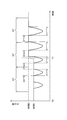
- FIG. 13 shows an example of a signal waveform in which the vertical axis represents the average signal intensity of the light receiving regions RA to RD and the horizontal axis represents time.
- the waveform indicated by the solid line is high in intensity immediately after output and is further lowered after a certain period of time. Therefore, when such a waveform is output from the proximity sensor 105, the control processing unit 121 determines that a gesture operation has been performed with the hand HD opened in the detection area closed.
- the waveform indicated by the dotted line is low in intensity immediately after output and increases further after a certain period of time. Therefore, when such a waveform is output from the proximity sensor 105, the control processing unit 121 determines that a gesture operation has been performed with the hand HD closed in the detection area opened.
- the proximity sensor by using the proximity sensor, the presence / absence of the hand HD and the movement and shape change are reliably detected by positioning the detection region within the visual field of the user's eye facing the image display unit. can do. Accordingly, the user US can view the hand operation and the operation in conjunction with each other, and can realize an intuitive operation. Furthermore, since the proximity sensor is small and consumes less power than the camera, the continuous operation time of the HMD 100 can be extended.
- the control processing unit 121 determines ambient brightness based on a signal from the illuminance sensor 112 and adjusts the luminance of an image displayed on the display unit 104 via the display control unit 104DR. More specifically, when the control processing unit 121 determines that the surrounding is relatively bright based on the signal from the illuminance sensor 112, the brightness of the image displayed on the display unit 104 is made bright and easy to see, When it is determined that the surroundings are relatively dark, the brightness of the image displayed on the display unit 104 is reduced to make it easy to see, thereby saving energy. This is a normal brightness adjustment mode (automatic brightness adjustment; also referred to as normal brightness adjustment mode). It is assumed that the luminance adjustment is not performed when the luminance adjustment mode is interrupted.
- the shadow of the hand HD may be applied to the illuminance sensor 112.
- the control processing unit 121 determines that the ambient brightness has become dark and reduces the brightness of the image.
- the movement of the hand HD in the gesture operation is often instantaneous, so that the shadow of the hand HD is separated from the illuminance sensor 112, and accordingly, the control processing unit 121 determines that the surrounding brightness has become brighter. This will increase the brightness of the image.
- the luminance of the image fluctuates according to the gesture operation, the user US may feel uncomfortable. Therefore, in the present embodiment, the following control is performed.
- FIG. 14 is a flowchart of brightness adjustment control executed by the control processing unit 121.
- the control processing unit 121 executes a normal luminance adjustment mode in accordance with an output signal from the illuminance sensor 112.
- the control processing unit 121 determines whether or not the hand HD as the indicator has entered the detection area SA (determination No in step S101).
- Step S101 When the user US causes the hand HD to enter the detection area SA for the gesture operation, the output signal of the proximity sensor 105 changes (Yes in Step S101), so that the control processing unit 121 performs a normal operation in Step S102. Suspend the brightness adjustment mode.
- the control processing unit 121 determines whether or not the hand HD as the indicator has stopped in the detection area SA for, for example, two seconds or more as the first specified time. Even when the hand HD is moved slowly, it is determined to be stopped as long as it remains in the detection area SA for 2 seconds or more.
- the control processing unit 121 When the hand HD does not stop in the detection area SA for 2 seconds or more, for example, and passes within less than 2 seconds, the control processing unit 121 returns the hand HD as the indicator to the detection area SA again in step S105. Judge whether to come back. For example, if it is determined that the hand HD does not return to the detection area SA within 2 seconds as the third specified time, the control processing unit 121 resumes the normal brightness adjustment mode in step S109.
- step S104 a special brightness adjustment mode corresponding to the gesture operation is set. Thereafter, the flow proceeds to step S107, and the control processing unit 121 executes the set special brightness adjustment mode.
- step S108 the control processing unit 121 determines whether or not the hand HD remains in the detection area SA, and if it is determined that the hand HD remains in the detection area SA, If the flow is returned to S102, but it is determined that the hand HD does not remain in the detection area SA, the normal luminance adjustment mode is resumed in Step S109.
- step S105 determines that the hand HD has returned to the detection area SA again (regardless of the return direction)
- the control processing unit 121 sets a special brightness adjustment mode corresponding to the gesture operation in step S106. . Thereafter, the flow proceeds to step S107, and the control processing unit 121 executes the set special brightness adjustment mode. Since step S107 and subsequent steps are the same, description thereof is omitted.
- FIG. 15 is a diagram schematically showing a gesture operation in which the hand HD passes through the detection area SA in less than 2 seconds, and is shown together with the proximity sensor 105.
- FIG. 15A when the hand HD is placed on the right side of the detection area SA and is moved to the left from the detection area SA, only the light receiving areas RA and RB of the proximity sensor 105 are first shown in FIG. Reacts as shown by hatching.
- FIG. 15C when the hand HD comes to the center of the detection area SA, the entire light receiving area of the proximity sensor 105 reacts as shown by hatching, and thereafter, in FIG.
- the control processing unit 121 interrupts the normal brightness adjustment mode when the state shown in FIG. 15B is determined, and resumes when the state shown in FIG. 15E is determined.
- FIG. 16 is a diagram schematically showing a gesture operation in which the hand HD stays in the detection area SA for 2 seconds or more.
- FIGS. 16A to 16C are similar to FIGS. 15A to 15C, but are examples in which the hand HD remains in FIG. 16D.
- the control processing unit 121 interrupts the normal brightness adjustment mode when the state of FIG. 16B is determined, and then sets the special brightness adjustment mode when the state of FIG. 16D is determined. .
- FIG. 17 is a diagram schematically illustrating a gesture operation in which the hand HD returns to the detection area SA.
- 17 (a) to 17 (d) are the same as FIGS. 15 (a) to 15 (d), but in FIG. 17 (e), the hand HD that has escaped from the detection area SA returns to the detection area SA again.
- the control processing unit 121 interrupts the normal brightness adjustment mode at the time when the state of FIG. 17B is determined, and then performs a gesture when it is determined that the state of FIG. Set the special brightness adjustment mode according to the operation.
- FIG. 18 is a diagram schematically showing a gesture operation in which the hand HD stays in the detection area SA for 2 seconds or more and rotates.
- 18A to 18C are the same as FIGS. 15A to 15C, but in FIG. 18D, the hand HD stays in the detection area SA and in front of the user US. It is the example rotated.
- the control processing unit 121 interrupts the normal brightness adjustment mode at the time when the state of FIG. 18B is determined, and then determines the special brightness corresponding to the gesture operation at the time of determining the state of FIG. Set the adjustment mode.
- FIG. 19 is a diagram schematically showing a gesture operation in which the hand HD remains in the detection area SA for 2 seconds or more and the shape is changed.
- FIGS. 19A to 19C are the same as FIGS. 15A to 15C, but in FIG. 19D, the hand HD remains in the detection area SA and is closed from the open state. It is an example that was changed to.
- the control processing unit 121 interrupts the normal brightness adjustment mode at the time when the state of FIG. 19B is determined, and then determines the special brightness corresponding to the gesture operation at the time of determining the state of FIG. Set the adjustment mode.
- FIG. 20 is a graph showing the luminance of the image displayed on the display on the vertical axis and the time on the horizontal axis.
- the alternate long and short dash line is a graph showing luminance adjustment in the normal luminance adjustment mode as a comparative example, and the solid line is a graph showing luminance adjustment in the special luminance adjustment mode.
- This special brightness adjustment mode is suitable when the gesture operation shown in FIG. 16 is performed.
- the proximity sensor 105 detects the hand HD in the stage shown in FIG. 16 (b).
- the illuminance sensor 112 detects the shadow of the hand HD at the time T1
- the minimum luminance value MIN for example, the same image
- the brightness is reduced at a stroke until the minimum value of the average brightness at the time of comparison.
- the hand HD exits from the detection area SA in a short time, if the brightness value of the image varies greatly, the user US may feel uncomfortable and energy saving cannot be achieved.
- the luminance adjustment is performed with a change rate smaller than the luminance reduction rate (change rate of luminance with respect to time) in the normal luminance adjustment mode. Furthermore, when the illuminance sensor 112 no longer detects the shadow of the hand HD at time T3, the brightness value is returned to the original maximum value MAX in any mode, but at the time T3, the brightness is increased by the normal brightness adjustment mode.
- the brightness value in the special brightness adjustment mode is higher than the value. That is, while the gesture operation is performed, the luminance value changes less, so it can be said that the user US is less likely to feel uncomfortable. Note that the brightness value is maximized when the hand HD is not detected, and the brightness value is minimized when the hand HD is detected.
- control is basically performed to change the brightness value according to the ambient brightness. Therefore, it is an example of the embodiment that the luminance value is maximized when the hand HD is not detected, and the luminance value is minimized when the hand HD is detected, and is not limited thereto. . The same applies to the following embodiments.
- the special brightness adjustment mode may be terminated and the normal brightness adjustment mode may be executed as indicated by a broken line.
- FIG. 21 is a graph in which the vertical axis represents the luminance of the image displayed on the display and the horizontal axis represents time.
- a one-dot chain line is a graph showing luminance adjustment in a normal luminance adjustment mode as a comparative example, and a solid line is a graph showing luminance adjustment in another special luminance adjustment mode. This special brightness adjustment mode is also suitable when the gesture operation shown in FIG. 16 is performed.
- the proximity sensor 105 detects the hand HD in the stage shown in FIG. 16 (b).
- the illuminance sensor 112 detects a shadow of the hand HD at time T1
- the luminance is reduced at a stroke to the minimum luminance value MIN2, as indicated by the alternate long and short dash line, in the luminance adjustment in the normal luminance adjustment mode as a comparative example.
- the brightness adjustment is performed by reducing the brightness at the same rate of change as the brightness reduction rate in the normal brightness adjustment mode, but the brightness value MID (special brightness) higher than the minimum value MIN2.
- the reduction is stopped at the minimum luminance value in the adjustment mode. Furthermore, when the illuminance sensor 112 no longer detects the shadow of the hand HD at time T3, the brightness value is restored to the original maximum value MAX in any mode, but even at time T3, the brightness is adjusted by the normal brightness adjustment mode.
- the minimum luminance value (MID) in the special luminance adjustment mode is higher than the value (MIN). In other words, while the gesture operation is performed, it can be said that the fluctuation of the luminance value is small and the user US is less likely to feel uncomfortable.
- the special brightness adjustment mode of this example when the time (second specified time) from time T1 to time T2 when the hand HD stays in the detection area SA is relatively long, for example, 5 seconds or more, As shown by the broken line, when the time T2 has passed, the special brightness adjustment mode may be terminated and the normal brightness adjustment mode may be resumed. Furthermore, luminance adjustment may be performed by combining the graphs of FIGS. Regardless of the example described above, for example, the control processing unit 121 executes a special brightness adjustment mode in which the brightness adjustment is not performed (the brightness value of the image is maintained) or the default brightness value is forcibly set. Also good.
- a special brightness adjustment mode in the case of a gesture operation in which the hand HD that has passed through the detection area SA returns will be described. Also in this case, if the time that the hand HD stays in the detection area SA is less than 2 seconds, for example, brightness adjustment is not performed, and if the time that the hand HD stays in the detection area SA is 2 seconds or more, for example, The brightness adjustment mode can be set to perform the brightness adjustment shown in FIGS. 20 and 21, or the brightness adjustment can be omitted. Also, in the case of the gesture operation shown in FIGS. 18 and 19, if the time that the hand HD stays in the detection area SA is, for example, less than 2 seconds, the brightness adjustment is not performed and the time that the hand HD stays in the detection area SA. If, for example, 2 seconds or longer, the special brightness adjustment mode can be set and the brightness adjustment shown in FIGS. 20 and 21 can be performed, or the brightness adjustment can not be performed.
- FIG. 22 is a graph showing ambient brightness based on the output signal of the illuminance sensor 112 and taking time on the horizontal axis, and shows an example in which continuous operation is performed.
- the maximum brightness value MXB is obtained when the hand HD is below the illuminance sensor 112 in FIG. 22, and the other brightness values are obtained when the hand HD is above the illuminance sensor 112. It is done.
- the control processing unit 121 can perform brightness adjustment. More specifically, the control processing unit 121 obtains the maximum brightness MXB during a certain sampling period ST (hereinafter referred to as a fourth specified time; for example, 2 seconds). When the maximum value fluctuates, the average value of the maximum values is obtained, and this is regarded as valid data, and the rest is regarded as invalid data. It is preferable that the control processing unit 121 performs brightness adjustment in the special brightness adjustment mode using only valid data. Since the maximum brightness value MXB indicates the brightness of the outside world and is substantially constant, appropriate brightness of the image can be realized by performing brightness control based on this value.
- FIG. 24 is a graph showing the ambient brightness based on the output signal of the illuminance sensor 112 and taking the time on the horizontal axis, and shows an example in which the ambient brightness becomes brighter at time T1 during continuous operation. ing. Also in this case, the maximum value MXB1 or MXB2 of brightness during a certain sampling period ST (for example, 2 seconds) is obtained, and this is set as valid data, and the other is set as invalid data. It is preferable that the control processing unit 121 performs brightness adjustment in the special brightness adjustment mode using only valid data.
- the control processing unit 121 can perform luminance adjustment in the special luminance adjustment mode.
- the special brightness adjustment mode set in this example may be executed.
- FIG. 25 is a graph showing the ambient brightness based on the output signal of the illuminance sensor 112 and taking the time on the horizontal axis, and shows an example in which such an operation is performed.
- the shadow of the hand on the illuminance sensor 112 fluctuates randomly, so that the ambient brightness based on the output signal fluctuates randomly as shown in FIG. It will be.
- the control processing unit 121 can perform luminance adjustment in the special luminance adjustment mode.
- the present invention has been described using the HMD as an example, but the present invention is not limited to the HMD and can be applied to all electronic devices such as portable terminals.
- HMD 101 Frame 101a Front part 101b Side part 101c Side part 101d Long hole 101e Long hole 102 Eyeglass lens 103 Main body part 104 Display 104A Image forming part 104B Image display part 104DR Display control part 104a Light source 104b Unidirectional diffuser 104c Condensing lens 104d Display element 104f Eyepiece prism 104g Deflection prism 104h Hologram optical element 104i Screen 105 Proximity sensor 105a Light receiving part 106 Camera 106a Lens 107 Right sub-main part 107a Protrusion 108 Left sub-main part 108a Protrusion 109 Acceleration sensor 111B Microphone 111C Speaker / Earphone 113 Color temperature Sensor 114 Temperature sensor 121 Control processing unit 122 Operation unit 123 GPS reception unit 124 Communication unit 125 ROM 126 RAM 127 Battery 129 Storage device 130 Power supply circuit CD Code CTU Control unit HD Hand HS Wiring PL1 Base end surface PL2 Inner side surface PL3 Outer side surface PL4
Abstract
The present invention provides an electronic device and a head-mounted display that are capable of appropriately adjusting the brightness of an image displayed on a screen while providing non-contact detection of movement and/or changes in shape of, e.g., an indicator for inputting gesture operations. In the electronic device, when an indicator detection device has detected that the indicator is within a detection area, a brightness control device interrupts execution of the normal brightness adjustment mode and executes a special brightness adjustment mode in accordance with movement and/or changes in shape of the indicator, the special brightness adjustment mode being different from the brightness adjustment mode.
Description
本発明は,画像表示装置を備えた電子機器及びヘッドマウントディスプレイに関する。
The present invention relates to an electronic device provided with an image display device and a head mounted display.
近年、急速に発達したスマートフォン等の携帯端末は、ビジネスや家庭での作業補助に用いられることも多い。一般的な携帯端末では、画像表示とユーザーインタフェースを兼ねるタッチパネル式の画面を備えているので、ユーザーはこれにタッチすることで必要な入力を行って、所望の画像を表示したり、情報を入力したりするなどの操作を行うことができる。ところで、画面に表示された画像の見やすさは、周囲の明るさに応じて変化する。すなわち、同じ輝度の画像でも、周囲が比較的明るい場合には見にくくなる一方、周囲が比較的暗ければ見やすくなる。そこで、一般的な携帯端末においては、照度センサなどを用いて周囲の明るさを検出し、検出した周囲の明るさに応じて画面に表示される画像の輝度を変化させる表示制御が行われている。
In recent years, mobile terminals such as smartphones that have been rapidly developed are often used for business and home work assistance. A typical mobile terminal has a touch panel screen that serves both as an image display and a user interface. By touching this screen, the user can make necessary inputs to display a desired image or input information. Can be performed. By the way, the visibility of the image displayed on the screen changes according to the ambient brightness. That is, even images with the same brightness are difficult to see when the surroundings are relatively bright, but are easy to see when the surroundings are relatively dark. Therefore, in general mobile terminals, display control is performed in which ambient brightness is detected using an illuminance sensor or the like, and the brightness of an image displayed on the screen is changed according to the detected ambient brightness. Yes.
一方、ユーザーの手が濡れていたり、汚れていたりする場合などに、画面にタッチせずに携帯端末の操作を行いたい場合がある。このような要請に応じて、携帯端末から出射された光をユーザーの手に反射させ、その反射光を赤外線近接センサが検出することで手の動きを検出し、その手の動き(ジェスチャー)により非接触でスワイプ等のユーザーの望む入力操作を行うことができる技術が既に開発されている。このような技術を用いれば、例えユーザーの手が汚れていても、携帯端末の画面を汚染する恐れがない。
On the other hand, when the user's hand is wet or dirty, there are cases where it is desired to operate the mobile terminal without touching the screen. In response to such a request, the light emitted from the mobile terminal is reflected on the user's hand, and the reflected light is detected by the infrared proximity sensor to detect the movement of the hand, and by the movement (gesture) of the hand. A technology capable of performing an input operation desired by a user such as swipe without contact has been developed. If such a technique is used, even if the user's hand is dirty, there is no possibility of contaminating the screen of the portable terminal.
しかし、このようにジェスチャーで入力操作を行う際に、手が照度センサに近接することで影を作り、この影の状態を照度センサが周囲の明るさとして誤検出する恐れがある。かかる場合、ジェスチャー操作を行うために手を接近/離間させると、そのたびに画面に表示される画像の輝度が変化して、ユーザーが違和感を覚える恐れがあり、また輝度制御のために消費電力も増大する恐れがある。
However, when performing an input operation with a gesture in this way, there is a possibility that a shadow will be created when the hand is close to the illuminance sensor, and the state of this shadow may be erroneously detected as ambient brightness. In such a case, the brightness of the image displayed on the screen may change every time the hand is moved closer / away to perform a gesture operation, and the user may feel uncomfortable, and power consumption for brightness control May also increase.
これに対し特許文献1には、光センサにより測定された明るさが明から暗に変化した場合において、タッチパネルの所定位置に接触があった場合、画面に表示される画像の輝度を低下させるタイミングを遅らせる携帯端末が開示されている。一方、特許文献2には、傾きセンサ及び近接センサを併用することで、表示部の輝度調整を有効/無効を切り換える技術が開示されている。仮に、かかる技術を組み合わせることができるとすると、ジェスチャー操作を行うために手を接近させた場合に、近接センサがこれを検知して通常の輝度調整を無効とすることが可能となり、それによりジェスチャー操作の度に画面に表示される画像の輝度が変化する不具合を回避できるともいえる。
On the other hand, in Patent Document 1, when the brightness measured by the optical sensor changes from light to dark, when there is a touch at a predetermined position on the touch panel, the timing of reducing the brightness of the image displayed on the screen. A mobile terminal that delays the delay is disclosed. On the other hand, Patent Document 2 discloses a technique for switching between enabling / disabling brightness adjustment of a display unit by using an inclination sensor and a proximity sensor together. If it is possible to combine such technologies, when a hand is approached to perform a gesture operation, it becomes possible for the proximity sensor to detect this and invalidate the normal brightness adjustment. It can be said that it is possible to avoid the problem that the brightness of the image displayed on the screen changes every time the operation is performed.
しかしながら、これらの公知技術を組み合わせることができたとしても、ユーザーが違和感を有効に解消できない恐れがある。より具体的には、例えばジェスチャー操作は、タップ動作と異なり、手などの指示体の移動や広範囲な形状変化を伴うので、それに応じて手の影になる範囲が大きく変化するから、より細やかな輝度調整が必要になる。
However, even if these known techniques can be combined, the user may not be able to effectively resolve the uncomfortable feeling. More specifically, for example, a gesture operation is different from a tapping operation, and involves movement of an indicator such as a hand and a wide range of shape changes. Brightness adjustment is required.
本発明は、上記の事情に鑑みてなされたものであって、例えばジェスチャー操作の入力のために指示体の動き及び/又は形状変化を非接触で検出しながらも、画面に表示される画像の輝度調整を適切に行える電子機器及びヘッドマウントディスプレイを提供することを目的とする。
The present invention has been made in view of the above circumstances. For example, an image displayed on a screen is detected while detecting movement and / or shape change of a pointer in a non-contact manner for input of a gesture operation. An object of the present invention is to provide an electronic device and a head mounted display capable of appropriately adjusting brightness.
上述した目的のうち少なくとも一つを実現するために、本発明の一側面を反映した電子機器は、
検出領域を持ち、ユーザーにより動かされる指示体が前記検出領域内に存在するか否か,及び前記検出領域内における前記指示体の動き及び/又は形状変化を非接触で検出する指示体検出装置と、
前記検出領域を含む周囲の明るさを検出する明るさ検出装置と、
画像を表示する画像表示装置と、
前記明るさ検出装置により検出された前記周囲の明るさに応じて、前記画像表示装置に表示される画像の輝度を調整する通常輝度調整モードを実行する輝度制御装置と、を有し、
前記指示体が前記検出領域内に存在することを前記指示体検出装置が検出したときは、前記輝度制御装置は、前記通常輝度調整モードの実行を中断し、前記指示体の動き及び/又は形状変化に応じて、前記輝度調整モードとは異なる特別輝度調整モードを実行するものである。 In order to achieve at least one of the above objects, an electronic device reflecting one aspect of the present invention is provided.
A pointer detection apparatus that has a detection region and detects whether or not a pointer moved by a user exists in the detection region, and movement and / or shape change of the pointer in the detection region in a non-contact manner; ,
A brightness detection device for detecting ambient brightness including the detection area;
An image display device for displaying an image;
A brightness control device that executes a normal brightness adjustment mode that adjusts the brightness of an image displayed on the image display device according to the ambient brightness detected by the brightness detection device;
When the indicator detection device detects that the indicator is present in the detection area, the luminance control device interrupts execution of the normal luminance adjustment mode, and the movement and / or shape of the indicator A special brightness adjustment mode different from the brightness adjustment mode is executed according to the change.
本発明によれば、例えばジェスチャー操作の入力のために指示体の動き及び/又は形状変化を非接触で検出しながらも、画面に表示される画像の輝度調整を適切に行える電子機器及びヘッドマウントディスプレイを提供することができる。
According to the present invention, for example, an electronic device and a head mount that can appropriately adjust the brightness of an image displayed on a screen while detecting movement and / or shape change of an indicator without contact for input of a gesture operation, for example. A display can be provided.
以下に、本発明の実施形態を、図面を参照して説明する。図1は、本実施形態にかかる、電子機器であるヘッドマウントディスプレイ(以下、HMDという)100の斜視図である。図2は、本実施形態にかかるHMD100を正面から見た図である。図3は、本実施形態にかかるHMD100を上方から見た図である。以下、HMD100の右側及左側とは、HMD100を装着したユーザーにとっての右側及び左側をいうものとする。
Embodiments of the present invention will be described below with reference to the drawings. FIG. 1 is a perspective view of a head mounted display (hereinafter referred to as HMD) 100 that is an electronic apparatus according to the present embodiment. FIG. 2 is a front view of the HMD 100 according to the present embodiment. FIG. 3 is a view of the HMD 100 according to the present embodiment as viewed from above. Hereinafter, the right side and the left side of the HMD 100 refer to the right side and the left side for the user wearing the HMD 100.
図1~3に示すように、本実施形態のHMD100は,支持部材であるフレーム101を有している。上方から見てコ字状であるフレーム101は、2つの眼鏡レンズ102を取り付ける前方部101aと、前方部101aの両端から後方へと延在する側部101b、101cとを有する。フレーム101に取り付けられた2つの眼鏡レンズ102は屈折力を有していてもよいし、有していなくてもよい。
As shown in FIGS. 1 to 3, the HMD 100 of this embodiment has a frame 101 as a support member. A frame 101 that is U-shaped when viewed from above has a front part 101a to which two spectacle lenses 102 are attached, and side parts 101b and 101c extending rearward from both ends of the front part 101a. The two spectacle lenses 102 attached to the frame 101 may or may not have refractive power.
右側(ユーザーの利き目などに応じて左側でもよい)の眼鏡レンズ102の上部において、支持部材である円筒状の主本体部103がフレーム101の前方部101aに固定されている。主本体部103にはディスプレイユニット104が設けられている。主本体部103内には、後述する制御処理部121からの指示に基づいてディスプレイユニット104の表示制御を司る表示制御部104DR(後述する図6を参照)が配置されている。なお、必要であれば両眼の前にそれぞれディスプレイユニットを配置してもよい。
A cylindrical main body 103 as a support member is fixed to the front portion 101a of the frame 101 on the upper side of the spectacle lens 102 on the right side (which may be on the left side depending on the user's dominant eye). The main body 103 is provided with a display unit 104. A display control unit 104DR (see FIG. 6 described later) that controls display control of the display unit 104 based on an instruction from the control processing unit 121 described later is disposed in the main body 103. If necessary, a display unit may be arranged in front of both eyes.
図4は、ディスプレイユニット104の構成を示す概略断面図である。画像表示装置であるディスプレイユニット104は、画像形成部104Aと画像表示部104Bとからなる。画像形成部104Aは、主本体部103内に組み込まれており、光源104aと、一方向拡散板104bと、集光レンズ104cと、表示素子104dとを有している。一方、いわゆるシースルー型の表示部材である画像表示部104Bは、主本体部103から下方に向かい、片方の眼鏡レンズ102(図1参照)に平行に延在するように配置された全体的に板状であって、接眼プリズム104fと、偏向プリズム104gと、ホログラム光学素子104hとを有している。
FIG. 4 is a schematic cross-sectional view showing the configuration of the display unit 104. The display unit 104 serving as an image display device includes an image forming unit 104A and an image display unit 104B. The image forming unit 104A is incorporated in the main body unit 103, and includes a light source 104a, a unidirectional diffuser 104b, a condenser lens 104c, and a display element 104d. On the other hand, the image display unit 104B, which is a so-called see-through type display member, is disposed on the entire plate so as to extend downward from the main body unit 103 and extend in parallel to one eyeglass lens 102 (see FIG. 1). The eyepiece prism 104f, the deflecting prism 104g, and the hologram optical element 104h.
次に、ディスプレイユニット104の動作について説明する。光源104aから出射された光は、一方向拡散板104bにて拡散され、集光レンズ104cにて集光されて表示素子104dに入射する。表示素子104dに入射した光は、表示制御部104DRから入力された画像データに基づいて画素ごとに変調され、画像光として出射される。これにより、表示素子104dには、カラー画像が表示される。
Next, the operation of the display unit 104 will be described. The light emitted from the light source 104a is diffused by the unidirectional diffusion plate 104b, condensed by the condenser lens 104c, and enters the display element 104d. The light incident on the display element 104d is modulated for each pixel based on the image data input from the display control unit 104DR, and is emitted as image light. Thereby, a color image is displayed on the display element 104d.
表示素子104dからの画像光は、接眼プリズム104fの内部にその基端面PL1から入射し、内側面PL2と外側面PL3で複数回全反射されて、ホログラム光学素子104hに入射する。ホログラム光学素子104hに入射した光は、そこで反射され、内側面PL2を透過して瞳孔Bに達する。瞳孔Bの位置では、ユーザーは、表示素子104dに表示された画像の拡大虚像を観察することができ、画像表示部104Bに形成される画面として視認することができる。この場合、ホログラム光学素子104hが画面を構成しているとみることもできるし、内側面PL2に画面が形成されているとみることもできる。なお、本明細書において「画面」というときは、表示される画像を指すこともある。
Image light from the display element 104d enters the eyepiece prism 104f from its base end face PL1, is totally reflected a plurality of times by the inner side face PL2 and the outer side face PL3, and enters the hologram optical element 104h. The light incident on the hologram optical element 104h is reflected there, passes through the inner side surface PL2, and reaches the pupil B. At the position of the pupil B, the user can observe an enlarged virtual image of the image displayed on the display element 104d, and can visually recognize it as a screen formed on the image display unit 104B. In this case, it can be considered that the hologram optical element 104h constitutes a screen, or it can be considered that a screen is formed on the inner surface PL2. In the present specification, “screen” may refer to an image to be displayed.
一方、接眼プリズム104f、偏向プリズム104gおよびホログラム光学素子104hは、外光をほとんど全て透過させるので、ユーザーはこれらを介して外界像(実像)を観察することができる。したがって、表示素子104dに表示された画像の虚像は、外界像の一部に重なって観察されることになる。このようにして、HMD100のユーザーは、ホログラム光学素子104hを介して、表示素子104dから提供される画像と外界像とを同時に観察することができる。尚、ディスプレイユニット104が非表示状態のとき画像表示部104Bは素通しとなり、外界像のみを観察できる。なお、本例では、光源と液晶表示素子と光学系とを組み合わせて表示ユニットを構成しているが、光源と液晶表示素子の組合せに代えて、自発光型の表示素子(例えば、有機EL表示素子)を用いても良い。また、光源と液晶表示素子と光学系の組合せに代えて、非発光状態で透過性を有する透過型有機EL表示パネルを用いてもよい。いずれにしても、画像表示部104Bに対向するユーザーの眼の視野に入るように、好ましくは、有効視野に少なくとも一部が重なるように、画面を配置すると、ユーザーは画像を容易に視認することができる。
On the other hand, since the eyepiece prism 104f, the deflecting prism 104g, and the hologram optical element 104h transmit almost all of the external light, the user can observe an external field image (real image) through them. Therefore, the virtual image of the image displayed on the display element 104d is observed so as to overlap with a part of the external image. In this manner, the user of the HMD 100 can simultaneously observe the image provided from the display element 104d and the external image via the hologram optical element 104h. Note that when the display unit 104 is in the non-display state, the image display unit 104B is transparent, and only the external image can be observed. In this example, a display unit is configured by combining a light source, a liquid crystal display element, and an optical system. However, instead of a combination of a light source and a liquid crystal display element, a self-luminous display element (for example, an organic EL display) is used. Element) may be used. Further, instead of a combination of a light source, a liquid crystal display element, and an optical system, a transmissive organic EL display panel having transparency in a non-light emitting state may be used. In any case, when the screen is arranged so as to fall within the visual field of the user's eye facing the image display unit 104B, and preferably at least partially overlaps the effective visual field, the user can easily visually recognize the image. Can do.
更に図1、2において、主本体部103の正面には、フレーム101の中央寄りに配置された近接センサ105と、フレーム101の側部寄りに配置されたカメラ106のレンズ106aと、近接センサ105とレンズ106aとの間に配置された照度センサ112とがそれぞれ前方を向くようにして設けられている。
Further, in FIGS. 1 and 2, on the front surface of the main body 103, the proximity sensor 105 disposed near the center of the frame 101, the lens 106 a of the camera 106 disposed near the side of the frame 101, and the proximity sensor 105. And the illuminance sensor 112 disposed between the lens 106a and the lens 106a so as to face each other.
明るさ検出装置の一例である照度センサは、例えばフォトダイオード等の光電変換素子を用いて周囲の明るさに応じた光電流を生成し、これをカレントミラーアンプで増幅することにより、所望の出力信号(出力電流)を生成するものであり、特開2009-158928号公報に記載されたものを用いることができるが、指示体検出装置の検出領域を含む周囲の明るさを検出できるものであれば、これに限られない。
An illuminance sensor, which is an example of a brightness detection device, generates a photocurrent according to the ambient brightness using a photoelectric conversion element such as a photodiode, for example, and amplifies this with a current mirror amplifier to obtain a desired output. A signal (output current) is generated, and the one described in Japanese Patent Application Laid-Open No. 2009-158928 can be used. However, it is possible to detect ambient brightness including the detection region of the indicator detection device. For example, it is not limited to this.
本明細書において、指示体検出装置の一例である「近接センサ」とは、物体、例えば人体の一部(手や指など)がユーザーの眼前に近接していることを検知するために、近接センサの検出面前方の近接範囲にある検出領域内に存在しているか否かを検出して信号を出力するものをいう。近接範囲は、操作者の特性や好みに応じて適宜設定すればよいが、例えば、近接センサの検出面からの距離が200mm以内の範囲とすることができる。近接センサからの距離が200mm以内であれば、ユーザーが腕を曲げた状態で、手のひらや指をユーザーの視野内に入れたり出したりできるため、手や指を使ったジェスチャーによって容易に操作を行うことができ、また、ユーザー以外の人体や家具等を誤って検出する恐れが少なくなる。ここで制御回路は、近接センサの前方の近接範囲にある検出領域に物体が入った際に近接センサから出力される信号に基づいて、物体が近接範囲に存在すると判定する。検出領域に物体が入った際に、近接センサから有効な信号を制御回路に出力するようにしても良い。
In this specification, the “proximity sensor” which is an example of the indicator detection device is a proximity sensor for detecting that an object, for example, a part of a human body (such as a hand or a finger) is close to the user's eyes. This means that a signal is output by detecting whether or not it exists in a detection area in the proximity range in front of the detection surface of the sensor. The proximity range may be set as appropriate according to the operator's characteristics and preferences. For example, the proximity range from the detection surface of the proximity sensor may be within a range of 200 mm. If the distance from the proximity sensor is 200 mm or less, the user can easily put the palm and fingers into and out of the user's field of view with the arm bent, so that the user can easily operate with gestures using the hands and fingers. In addition, the risk of erroneous detection of a human body or furniture other than the user is reduced. Here, the control circuit determines that the object exists in the proximity range based on a signal output from the proximity sensor when the object enters the detection area in the proximity range in front of the proximity sensor. When an object enters the detection area, an effective signal may be output from the proximity sensor to the control circuit.
近接センサには、パッシブ型とアクティブ型とがある。パッシブ型の近接センサは、物体が近接した際に物体から放射される不可視光や電磁波を検出する検出部を有する。パッシブ型の近接センサとしては、接近した人体から放射される赤外線などの不可視光を検出する焦電センサや、接近した人体との間の静電容量変化を検出する静電容量センサなどがある。アクティブ型の近接センサは、不可視光や音波の投射部と、物体に反射して戻った不可視光や音波を受ける検出部とを有する。アクティブ型の近接センサとしては、赤外線を投射して物体で反射された赤外線を受光する赤外線センサや、レーザ光を投射して物体で反射されたレーザ光を受光するレーザセンサや、超音波を投射して物体で反射された超音波を受け取る超音波センサなどがある。尚、パッシブ型の近接センサは、物体に向けてエネルギーを投射する必要がないので、低消費電力性に優れている。アクティブ型の近接センサは検知の確実性を向上させやすく、例えば、ユーザーが、赤外光などの人体から放射される検出光を透過しない手袋をしているような場合でも、ユーザーの手の動きを検出することができる。複数種類の近接センサを組み合わせて用いても良い。
There are two types of proximity sensors: passive type and active type. A passive proximity sensor has a detection unit that detects invisible light and electromagnetic waves emitted from an object when the object approaches. As a passive proximity sensor, there are a pyroelectric sensor that detects invisible light such as infrared rays emitted from an approaching human body, and a capacitance sensor that detects a change in electrostatic capacitance between the approaching human body and the like. The active proximity sensor includes an invisible light and sound wave projection unit, and a detection unit that receives the invisible light and sound wave reflected and returned from the object. Active proximity sensors include infrared sensors that project infrared rays and receive infrared rays reflected by objects, laser sensors that project laser beams and receive laser beams reflected by objects, and project ultrasonic waves. Then, there is an ultrasonic sensor that receives ultrasonic waves reflected by an object. Note that a passive proximity sensor does not need to project energy toward an object, and thus is excellent in low power consumption. Active proximity sensors can improve detection reliability. For example, even if the user is wearing gloves that do not transmit detection light emitted from the human body such as infrared light, the movement of the user's hand Can be detected. A plurality of types of proximity sensors may be used in combination.
近接センサは、カメラに比べて、概して小型で安価であり、消費電力も小さい。また、近接センサは、物体の形状の検出など複雑な検出を行うことは難しいが、検出領域への物体の進入や離間を判別することができるので、ユーザーが手や指を通過させたり手のひらをかざしたりすることで、HMDの操作を行うことができ、しかも、カメラの撮影画像の解析によるジェスチャー認識に必要とされる複雑な画像処理も不要である。
Proximity sensors are generally smaller and cheaper than cameras, and consume less power. In addition, it is difficult for the proximity sensor to perform complicated detection such as detection of the shape of the object, but it can determine the approach and separation of the object from the detection area, so that the user can pass the hand or finger or the palm of the hand. By holding it over, the HMD can be operated, and complicated image processing required for gesture recognition by analysis of the image captured by the camera is also unnecessary.
図5は、本実施形態で用いる近接センサ105を正面から見た拡大図である。本実施形態では、近接センサ105として、焦電センサを用いた例について説明する。図5において、近接センサ105は、人体から放射される赤外光などの不可視光を検出光として受光する受光部105aを有する。受光部105aは、2行2列に並べられた受光領域RA~RDを形成しており、不可視光を受光した際に、それに対応した信号が各受光領域RA~RDから個々に出力されるようになっている。各受光領域RA~RDの出力は、受光部105aから物体までの距離に応じて強度が変化し、距離が近いほど強度が大きくなる。人体から放射される赤外光を検出する焦電センサであれば、露出した人体以外の物体を誤検出しくにいので、例えば、狭所で作業する場合などにおいて、効果的に誤検出を防ぐことができるというメリットがある。
FIG. 5 is an enlarged view of the proximity sensor 105 used in the present embodiment as viewed from the front. In the present embodiment, an example in which a pyroelectric sensor is used as the proximity sensor 105 will be described. In FIG. 5, the proximity sensor 105 includes a light receiving unit 105 a that receives invisible light such as infrared light emitted from a human body as detection light. The light receiving unit 105a forms light receiving areas RA to RD arranged in 2 rows and 2 columns, and when receiving invisible light, signals corresponding to the light receiving areas RA to RD are individually output from the light receiving areas RA to RD. It has become. The output of each of the light receiving areas RA to RD changes in intensity according to the distance from the light receiving unit 105a to the object, and the intensity increases as the distance decreases. If it is a pyroelectric sensor that detects infrared light emitted from the human body, it is difficult to falsely detect an object other than the exposed human body. For example, when working in a narrow space, the false detection is effectively prevented. There is an advantage that you can.
図1、2において、フレーム101の右側の側部101bには、右副本体部107が取り付けられ、フレーム101の左側の側部101cには、左副本体部108が取り付けられている。右副本体部107及び左副本体部108は、細長い板形状を有しており、それぞれ内側に細長い突起107a,108aを有している。この細長い突起107aを、フレーム101の側部101bの長孔101dに係合させることで、右副本体部107が位置決めされた状態でフレーム101に取り付けられ、また細長い突起108aを、フレーム101の側部101cの長孔101eに係合させることで、左副本体部108が位置決めされた状態でフレーム101に取り付けられている。
1 and 2, the right sub-body portion 107 is attached to the right side portion 101b of the frame 101, and the left sub-body portion 108 is attached to the left side portion 101c of the frame 101. The right sub-main body portion 107 and the left sub-main body portion 108 have an elongated plate shape, and have elongated protrusions 107a and 108a on the inner side, respectively. By engaging the elongated protrusion 107 a with the elongated hole 101 d of the side portion 101 b of the frame 101, the right sub-body portion 107 is attached to the frame 101 in a positioned state, and the elongated protrusion 108 a is attached to the side of the frame 101. By engaging with the long hole 101e of the portion 101c, the left sub-main body portion 108 is attached to the frame 101 in a positioned state.
右副本体部107内には、地磁気を検出する地磁気センサ109(後述する図6参照)と、姿勢に応じた出力を生成する、角速度センサ110B及び加速度センサ110A(後述する図6参照)とが搭載されており、左副本体部108内には、スピーカー・イヤホン111C及びマイク111B(後述する図6参照)とが設けられている。主本体部103と右副本体部107とは、配線HSで信号伝達可能に接続されており、主本体部103と左副本体部108とは、不図示の配線で信号伝達可能に接続されている。図3に簡略図示するように、右副本体部107は、その後端から延在するコードCDを介して制御ユニットCTUに接続されている。なお、角速度センサ及び加速度センサを一体化した6軸センサを用いてもよい。また、入力される音声に応じてマイク111Bから生成される出力信号に基づいて、音声によってHMDを操作することもできる。また、主本体部103と左副本体部108とが無線接続されるように構成してもよい。又、色温度センサ113や温度センサ114を設けることは任意である。
In the right sub-body portion 107, there are a geomagnetic sensor 109 (see FIG. 6 to be described later) for detecting geomagnetism, and an angular velocity sensor 110B and an acceleration sensor 110A (see FIG. 6 to be described later) that generate an output corresponding to the posture. The left sub-main body 108 is provided with a speaker / earphone 111C and a microphone 111B (see FIG. 6 described later). The main main body 103 and the right sub main body 107 are connected so as to be able to transmit signals through a wiring HS, and the main main body 103 and the left sub main body 108 are connected so as to be able to transmit signals through a wiring (not shown). Yes. As schematically illustrated in FIG. 3, the right sub-main body 107 is connected to the control unit CTU via a cord CD extending from the rear end. A 6-axis sensor in which an angular velocity sensor and an acceleration sensor are integrated may be used. Further, the HMD can be operated by sound based on an output signal generated from the microphone 111B according to the input sound. Further, the main main body 103 and the left sub main body 108 may be configured to be wirelessly connected. The color temperature sensor 113 and the temperature sensor 114 are optional.
図6は、HMD100の主要回路のブロック図である。制御ユニットCTUは、ディスプレイユニット104やその他の機能デバイスに対して制御信号を生成する、輝度制御装置としての制御処理部121と、操作部122と、GPS衛星からの電波を受信するGPS受信部123と、外部とデータのやりとりを行う通信部124と、プログラム等を格納するROM125と、画像データ等を保存するRAM126と、バッテリー127から付与された電圧を各部に適正な電圧に変換するための電源回路130と、SSDやフラッシュメモリ等のストレージデバイス129とを有している。制御処理部121はスマートフォンなどで用いられているアプリケーションプロセッサーを使用することが出来るが、制御処理部121の種類は問わない。例えば、アプリケーションプロセッサーの内部にGPUやCodecなど画像処理に必要なハードウェアが標準で組み込まれているものは、小型のHMDには適したプロセッサーであるといえる。制御処理部121は、後述する輝度調整を行うために、制御部121A,ジェスチャー処理部121B,検知結果利用部121Cを含む。
FIG. 6 is a block diagram of main circuits of the HMD 100. The control unit CTU generates a control signal for the display unit 104 and other functional devices, a control processing unit 121 as a luminance control device, an operation unit 122, and a GPS receiving unit 123 that receives radio waves from GPS satellites. A communication unit 124 for exchanging data with the outside, a ROM 125 for storing programs and the like, a RAM 126 for storing image data and the like, and a power source for converting the voltage applied from the battery 127 into an appropriate voltage for each unit The circuit 130 and a storage device 129 such as an SSD or a flash memory are included. Although the control processor 121 can use an application processor used in a smartphone or the like, the type of the control processor 121 is not limited. For example, if an application processor includes hardware necessary for image processing such as GPU or Codec as a standard, it can be said that the processor is suitable for a small HMD. The control processing unit 121 includes a control unit 121A, a gesture processing unit 121B, and a detection result using unit 121C in order to perform luminance adjustment described later.
更に、制御処理部121には、受光部105aが人体から放射される検出光としての不可視光を検出したときは、近接センサ105からその信号が入力され、また周囲の明るさを検出する照度センサ112からの信号が入力される。更に、制御処理部121は、表示制御部104DRを介してディスプレイユニット104の画像表示を制御する。
Furthermore, when the light receiving unit 105a detects invisible light as detection light emitted from the human body, the signal is input from the proximity sensor 105 to the control processing unit 121, and an illuminance sensor that detects ambient brightness. The signal from 112 is input. Further, the control processing unit 121 controls image display on the display unit 104 via the display control unit 104DR.
制御処理部121は、電源回路130からの給電を受け、ROM124及びストレージデバイス129の少なくとも一方に格納されたプログラムに従って動作し、操作部122からの電源オンなどの操作入力に従い、カメラ106からの画像データを入力してRAM126に記憶し、必要に応じて通信部124を介して外部と通信を行うことができる。更に、制御処理部121が近接センサ105からの出力に応じた画像制御を実行することで、ユーザーは手や指を用いたジェスチャー操作によってHMD100の画面制御を行うことができる。画面制御の例としては、ページめくり、スクロール、選択、決定などがあるが、詳細は省略する。
The control processing unit 121 receives power from the power supply circuit 130, operates according to a program stored in at least one of the ROM 124 and the storage device 129, and receives an image from the camera 106 according to an operation input such as power-on from the operation unit 122. Data can be input and stored in the RAM 126, and can be communicated with the outside via the communication unit 124 as necessary. Furthermore, when the control processing unit 121 executes image control according to the output from the proximity sensor 105, the user can perform screen control of the HMD 100 by gesture operation using a hand or a finger. Examples of screen control include page turning, scrolling, selection, and determination, but details are omitted.
図7は、ユーザーUSが本実施形態のHMD100を装着したときの正面図である。図8は、ユーザーUSがHMD100を装着したときの側面図であり、図9はその上面図であり、ユーザーの手と共に示している。ここで、ジェスチャー操作とは、少なくともユーザーUSの手HDや指が近接センサ105の検出領域内を通過する動作又は形状を変える動作であり、近接センサ105を介してHMD100の制御処理部121が検出できるものである。
FIG. 7 is a front view when the user US wears the HMD 100 of the present embodiment. FIG. 8 is a side view when the user US wears the HMD 100, and FIG. 9 is a top view thereof, which is shown together with the user's hand. Here, the gesture operation is an operation in which at least the hand HD or finger of the user US passes through the detection area of the proximity sensor 105 or an action of changing the shape, and is detected by the control processing unit 121 of the HMD 100 via the proximity sensor 105. It can be done.
次に、ジェスチャー操作の検出の基本原理について説明する。近接センサ105が作動しているときに、ユーザーUSの前方に何も存在しなければ、受光部105aは検出光としての不可視光を受光しないので、制御処理部121はジェスチャー操作が行われていないと判断する。一方、図8に示すように、ユーザーUSの目の前にユーザーUS自身の手HDを接近させると、手HDから放射される不可視光を受光部105aが検出し、これに基づく近接センサ105からの出力信号に応じて制御処理部121はジェスチャー操作が行われたと判断する。なお、以下においては、ユーザーの手HDによってジェスチャー操作を行うものとして説明するが、指やその他の部位であってもよいし、不可視光を放射できる材料からなる指示具をユーザーが用いてジェスチャー操作を行ってもよい。ユーザーの意思で移動させられるものを指示体という。尚、検出装置として、近接センサの代りに撮像装置(カメラ)を使用することも可能である。かかる場合、移動する指示体を撮像装置で撮像し、その移動方向を、撮像装置から出力した画像データに基づき画像処理装置(制御装置の一部)で判別することになる。
Next, the basic principle of gesture operation detection will be described. If nothing is present in front of the user US when the proximity sensor 105 is operating, the light receiving unit 105a does not receive invisible light as detection light, and thus the control processing unit 121 is not performing a gesture operation. Judge. On the other hand, as shown in FIG. 8, when the user US's own hand HD is approached in front of the user US, the light receiving unit 105a detects the invisible light emitted from the hand HD, and the proximity sensor 105 based on the invisible light is detected. In response to the output signal, the control processing unit 121 determines that a gesture operation has been performed. In the following description, it is assumed that the gesture operation is performed by the user's hand HD. However, the gesture operation may be performed by the user using a pointing device made of a material that can emit invisible light. May be performed. An indicator can be moved by the user's intention. Note that an imaging device (camera) can be used as the detection device instead of the proximity sensor. In such a case, the moving indicator is imaged by the imaging device, and the moving direction is determined by the image processing device (part of the control device) based on the image data output from the imaging device.
上述したように、受光部105aは、2行2列に並べられた受光領域RA~RDを有する(図5参照)。従って、ユーザーUSが、左右上下いずれの方向から手HDをHMD100の前方に近づけた場合、各受光領域RA~RDで検出する信号の出力タイミングが異なる。
As described above, the light receiving unit 105a has the light receiving regions RA to RD arranged in 2 rows and 2 columns (see FIG. 5). Therefore, when the user US moves the hand HD closer to the front of the HMD 100 from either the left, right, up, or down directions, the output timings of signals detected in the light receiving areas RA to RD are different.
図10、11は、縦軸に受光領域RA~RDの信号強度をとり、横軸に時間をとって示した、受光領域RA~RDの信号波形の一例である。例えば、図8、図9を参照してユーザーUSがHMD100の前方で右方から左方に向かって手HDを移動させた場合、手HDから放射された不可視光が受光部105aに入射するが、このとき最初に不可視光を受光するのは受光領域RA,RCである。従って、図10に示すように、まず受光領域RA,RCの信号が立ち上がり、遅れて受光領域RB,RDの信号が立ち上がり、更に受光領域RA,RCの信号が立ち下がった後に、受光領域RB,RDの信号が立ち下がる。この信号のタイミングを制御処理部121が検出し、ユーザーUSは手HDを右から左へと移動させてジェスチャー操作を行ったと判断する。
10 and 11 are examples of signal waveforms of the light receiving areas RA to RD, where the vertical axis represents the signal intensity of the light receiving areas RA to RD and the horizontal axis represents the time. For example, when the user US moves the hand HD from the right to the left in front of the HMD 100 with reference to FIGS. 8 and 9, invisible light emitted from the hand HD enters the light receiving unit 105a. In this case, the light receiving areas RA and RC first receive invisible light. Therefore, as shown in FIG. 10, first, the signals in the light receiving areas RA and RC rise, the signals in the light receiving areas RB and RD rise later, and the signals in the light receiving areas RA and RC fall, and then the light receiving areas RB, The RD signal falls. The control processing unit 121 detects the timing of this signal, and determines that the user US has performed the gesture operation by moving the hand HD from the right to the left.
図11の例では、まず受光領域RA,RBの信号が立ち上がり、遅れて受光領域RC,RDの信号が立ち上がり、更に受光領域RA,RBの信号が立ち下がった後に、受光領域RC,RDの信号が立ち下がっている。この信号のタイミングを制御処理部121が検出し、ユーザーUSは手HDを上から下へと移動させてジェスチャー操作を行ったと判断する。
In the example of FIG. 11, the signals of the light receiving areas RA and RB rise first, the signals of the light receiving areas RC and RD rise after a delay, and the signals of the light receiving areas RA and RB further fall, and then the signals of the light receiving areas RC and RD. Is falling. The control processing unit 121 detects the timing of this signal, and determines that the user US has performed the gesture operation by moving the hand HD from the top to the bottom.
更に、近接センサ105からの出力に基づいて、制御処理部121は、手HDが前後方向に移動したことも検出できる。図12には、縦軸に受光領域RA~RDの平均信号強度をとり、横軸に時間をとって示した信号波形の一例である。実線で示す波形は、出力直後に強度が高く、時間経過と共に低下している。よって、このような波形が近接センサ105から出力された場合、制御処理部121は、手HDを顔の近くから遠ざけるよう移動させてジェスチャー操作を行ったと判断する。一方、点線で示す波形は、出力直後に強度が低く、時間経過と共に上昇している。よって、このような波形が近接センサ105から出力された場合、制御処理部121は、手HDを遠くから顔に近づけるよう移動させてジェスチャー操作を行ったと判断する。
Furthermore, based on the output from the proximity sensor 105, the control processing unit 121 can also detect that the hand HD has moved in the front-rear direction. FIG. 12 shows an example of a signal waveform in which the vertical axis represents the average signal intensity of the light receiving regions RA to RD and the horizontal axis represents time. The waveform indicated by the solid line is high in intensity immediately after output and decreases with time. Therefore, when such a waveform is output from the proximity sensor 105, the control processing unit 121 determines that the gesture operation is performed by moving the hand HD away from the vicinity of the face. On the other hand, the waveform indicated by the dotted line is low in intensity immediately after output and increases with time. Therefore, when such a waveform is output from the proximity sensor 105, the control processing unit 121 determines that the gesture operation is performed by moving the hand HD so as to approach the face from a distance.
加えて、近接センサ105からの出力に基づいて、制御処理部121は、手HDの形状変化を検出できる。図13には、縦軸に受光領域RA~RDの平均信号強度をとり、横軸に時間をとって示した信号波形の一例である。実線で示す波形は、出力直後に強度が高く、一定時間経過後に一段低下している。よって、このような波形が近接センサ105から出力された場合、制御処理部121は、検出領域内で開いた手HDを閉じたジェスチャー操作を行ったと判断する。一方、点線で示す波形は、出力直後に強度が低く、一定時間経過後に一段増大している。よって、このような波形が近接センサ105から出力された場合、制御処理部121は、検出領域内で閉じた手HDを開いたジェスチャー操作を行ったと判断する。
In addition, based on the output from the proximity sensor 105, the control processing unit 121 can detect a shape change of the hand HD. FIG. 13 shows an example of a signal waveform in which the vertical axis represents the average signal intensity of the light receiving regions RA to RD and the horizontal axis represents time. The waveform indicated by the solid line is high in intensity immediately after output and is further lowered after a certain period of time. Therefore, when such a waveform is output from the proximity sensor 105, the control processing unit 121 determines that a gesture operation has been performed with the hand HD opened in the detection area closed. On the other hand, the waveform indicated by the dotted line is low in intensity immediately after output and increases further after a certain period of time. Therefore, when such a waveform is output from the proximity sensor 105, the control processing unit 121 determines that a gesture operation has been performed with the hand HD closed in the detection area opened.
本実施形態によれば、近接センサを用いて、その検出領域が画像表示部に対向するユーザーの眼の視野内に位置させることで、確実に手HDの存在の有無と移動及び形状変化を検出することができる。従って、ユーザーUSは手の動作と操作を連動させて見ることができ、直感的な操作を実現できる。更に、近接センサは、小型でカメラより低消費電力であるから、HMD100の連続動作時間を長くすることができる。
According to the present embodiment, by using the proximity sensor, the presence / absence of the hand HD and the movement and shape change are reliably detected by positioning the detection region within the visual field of the user's eye facing the image display unit. can do. Accordingly, the user US can view the hand operation and the operation in conjunction with each other, and can realize an intuitive operation. Furthermore, since the proximity sensor is small and consumes less power than the camera, the continuous operation time of the HMD 100 can be extended.
一方、制御処理部121は、照度センサ112からの信号に基づいて周囲の明るさを判定し、表示制御部104DRを介してディスプレイユニット104に表示される画像の輝度を調整する。より具体的に制御処理部121は、照度センサ112からの信号に基づいて周囲が比較的明るいと判定したときは、ディスプレイユニット104に表示される画像の輝度を明るくして見やすいものとし、一方、周囲が比較的暗いと判定したときは、ディスプレイユニット104に表示される画像の輝度を暗くして見やすいものとし、省エネを図っている。これを通常の輝度調整モード(自動輝度調整;通常輝度調整モードともいう)とする。輝度調整モードを中断した場合、輝度調整は行われないものとする。
On the other hand, the control processing unit 121 determines ambient brightness based on a signal from the illuminance sensor 112 and adjusts the luminance of an image displayed on the display unit 104 via the display control unit 104DR. More specifically, when the control processing unit 121 determines that the surrounding is relatively bright based on the signal from the illuminance sensor 112, the brightness of the image displayed on the display unit 104 is made bright and easy to see, When it is determined that the surroundings are relatively dark, the brightness of the image displayed on the display unit 104 is reduced to make it easy to see, thereby saving energy. This is a normal brightness adjustment mode (automatic brightness adjustment; also referred to as normal brightness adjustment mode). It is assumed that the luminance adjustment is not performed when the luminance adjustment mode is interrupted.
ここで、ユーザーUSがジェスチャー操作のために手HDを近接センサ105の検出領域SA内に接近させると、手HDの影が照度センサ112にかかることがある。通常の輝度調整モードが設定されている場合には、照度センサ112の出力信号に基づいて、制御処理部121が周囲の明るさが暗くなったと判定して、画像の輝度を低下させることとなる。一方、ジェスチャー操作における手HDの移動は一瞬であることが多く、それにより手HDの影は照度センサ112から離れるため、それに応じて制御処理部121は周囲の明るさが明るくなったと判定して、画像の輝度を増大させることとなる。このように、ジェスチャー操作に応じて画像の輝度が変動すると、ユーザーUSは違和感を覚える恐れがある。そこで、本実施形態では、以下のような制御を行っている。
Here, when the user US brings the hand HD closer to the detection area SA of the proximity sensor 105 for a gesture operation, the shadow of the hand HD may be applied to the illuminance sensor 112. When the normal brightness adjustment mode is set, based on the output signal of the illuminance sensor 112, the control processing unit 121 determines that the ambient brightness has become dark and reduces the brightness of the image. . On the other hand, the movement of the hand HD in the gesture operation is often instantaneous, so that the shadow of the hand HD is separated from the illuminance sensor 112, and accordingly, the control processing unit 121 determines that the surrounding brightness has become brighter. This will increase the brightness of the image. As described above, when the luminance of the image fluctuates according to the gesture operation, the user US may feel uncomfortable. Therefore, in the present embodiment, the following control is performed.
図14は、制御処理部121が実行する輝度調整の制御のフローチャートである。ここで、制御処理部121は照度センサ112からの出力信号に応じて、通常の輝度調整モードを実行しているものとする。かかる状態で、図14のステップS101で、制御処理部121は、指示体としての手HDが検出領域SA内に進入しているかどうかを判断する(ステップS101で判定No)。
FIG. 14 is a flowchart of brightness adjustment control executed by the control processing unit 121. Here, it is assumed that the control processing unit 121 executes a normal luminance adjustment mode in accordance with an output signal from the illuminance sensor 112. In this state, in step S101 of FIG. 14, the control processing unit 121 determines whether or not the hand HD as the indicator has entered the detection area SA (determination No in step S101).
ユーザーUSがジェスチャー操作のために手HDを検出領域SA内に進入させたとき、近接センサ105の出力信号が変化するので(ステップS101で判定Yes)、制御処理部121は、ステップS102で通常の輝度調整モードを中断する。続くステップS103で、制御処理部121は、指示体としての手HDが検出領域SA内に例えば第1の規定時間として2秒以上停止しているか否か判断する。手HDをゆっくり移動させている場合も、検出領域SA内に2秒以上留まる限り、停止しているものと判定する。
When the user US causes the hand HD to enter the detection area SA for the gesture operation, the output signal of the proximity sensor 105 changes (Yes in Step S101), so that the control processing unit 121 performs a normal operation in Step S102. Suspend the brightness adjustment mode. In subsequent step S103, the control processing unit 121 determines whether or not the hand HD as the indicator has stopped in the detection area SA for, for example, two seconds or more as the first specified time. Even when the hand HD is moved slowly, it is determined to be stopped as long as it remains in the detection area SA for 2 seconds or more.
手HDが検出領域SA内に例えば2秒以上停止せず、2秒未満で通過してしまった場合、制御処理部121は、ステップS105で、指示体としての手HDが再び検出領域SA内に戻ってくるか否か判断する。例えば第3の規定時間としての2秒以内に手HDが再び検出領域SA内に戻って来ないと判断した場合、制御処理部121は、ステップS109で通常の輝度調整モードを再開する。
When the hand HD does not stop in the detection area SA for 2 seconds or more, for example, and passes within less than 2 seconds, the control processing unit 121 returns the hand HD as the indicator to the detection area SA again in step S105. Judge whether to come back. For example, if it is determined that the hand HD does not return to the detection area SA within 2 seconds as the third specified time, the control processing unit 121 resumes the normal brightness adjustment mode in step S109.
これに対し、指示体としての手HDが検出領域SA内に例えば第1の規定時間として2秒以上停止している場合、制御処理部121は、ステップS103で手HDが検出領域SA内に留まっていると判断し、ステップS104でジェスチャー操作に応じた特別輝度調整モードを設定する。その後、フローはステップS107に移行して、制御処理部121は、設定された特別輝度調整モードを実行する。続くステップS108で、制御処理部121は、手HDが検出領域SA内に留まっているか否か判断し、手HDが検出領域SA内に留まっていると判断した場合、制御処理部121は、ステップS102にフローを戻す一方、手HDが検出領域SA内に留まっていないと判断した場合、ステップS109で通常の輝度調整モードを再開する。
On the other hand, when the hand HD as the indicator is stopped in the detection area SA for, for example, 2 seconds or more as the first specified time, the control processing unit 121 keeps the hand HD in the detection area SA in step S103. In step S104, a special brightness adjustment mode corresponding to the gesture operation is set. Thereafter, the flow proceeds to step S107, and the control processing unit 121 executes the set special brightness adjustment mode. In subsequent step S108, the control processing unit 121 determines whether or not the hand HD remains in the detection area SA, and if it is determined that the hand HD remains in the detection area SA, If the flow is returned to S102, but it is determined that the hand HD does not remain in the detection area SA, the normal luminance adjustment mode is resumed in Step S109.
更にステップS105で、手HDが再び検出領域SA内に戻ってきた(戻り方向は問わない)と判断した場合、制御処理部121は、ステップS106でジェスチャー操作に応じた特別輝度調整モードを設定する。その後、フローはステップS107に移行して、制御処理部121は、設定された特別輝度調整モードを実行する。ステップS107以降は同様であるため、説明を省略する。
Further, if it is determined in step S105 that the hand HD has returned to the detection area SA again (regardless of the return direction), the control processing unit 121 sets a special brightness adjustment mode corresponding to the gesture operation in step S106. . Thereafter, the flow proceeds to step S107, and the control processing unit 121 executes the set special brightness adjustment mode. Since step S107 and subsequent steps are the same, description thereof is omitted.
図15は、検出領域SAを手HDが2秒未満で通過するジェスチャー操作を模式的に示す図であり、近接センサ105と共に示している。図15(a)に示すように、手HDを検出領域SAの右方におき、ここから左方へと移動させると、図15(b)において、まず近接センサ105の受光領域RA,RBのみがハッチングで示すように反応する。更に、図15(c)に示すように、手HDが検出領域SAの中央にくると、近接センサ105の全受光領域がハッチングで示すように反応し、その後、図15(d)において、手HDを同方向に移動させると、近接センサ105の受光領域RC,RDのみがハッチングで示すように反応し、図15(e)に示すように、手HDが検出領域SAから抜け出ると、全受光領域が反応しなくなる。かかる場合、制御処理部121は、図15(b)の状態を判定した時点で通常の輝度調整モードを中断し、図15(e)の状態を判定した時点でこれを再開する。
FIG. 15 is a diagram schematically showing a gesture operation in which the hand HD passes through the detection area SA in less than 2 seconds, and is shown together with the proximity sensor 105. As shown in FIG. 15A, when the hand HD is placed on the right side of the detection area SA and is moved to the left from the detection area SA, only the light receiving areas RA and RB of the proximity sensor 105 are first shown in FIG. Reacts as shown by hatching. Further, as shown in FIG. 15C, when the hand HD comes to the center of the detection area SA, the entire light receiving area of the proximity sensor 105 reacts as shown by hatching, and thereafter, in FIG. When the HD is moved in the same direction, only the light receiving regions RC and RD of the proximity sensor 105 react as shown by hatching, and as shown in FIG. The region becomes unresponsive. In such a case, the control processing unit 121 interrupts the normal brightness adjustment mode when the state shown in FIG. 15B is determined, and resumes when the state shown in FIG. 15E is determined.
図16は、検出領域SAに手HDが2秒以上留まるジェスチャー操作を模式的に示す図である。図16(a)~(c)は、図15(a)~(c)と同様であるが,図16(d)で手HDが留まっている例である。かかる場合、制御処理部121は、図16(b)の状態を判定した時点で通常の輝度調整モードを中断した後、図16(d)の状態を判定した時点で特別輝度調整モードを設定する。
FIG. 16 is a diagram schematically showing a gesture operation in which the hand HD stays in the detection area SA for 2 seconds or more. FIGS. 16A to 16C are similar to FIGS. 15A to 15C, but are examples in which the hand HD remains in FIG. 16D. In such a case, the control processing unit 121 interrupts the normal brightness adjustment mode when the state of FIG. 16B is determined, and then sets the special brightness adjustment mode when the state of FIG. 16D is determined. .
図17は、検出領域SAに手HDが戻ってくるジェスチャー操作を模式的に示す図である。図17(a)~(d)は、図15(a)~(d)と同様であるが,図17(e)で、検出領域SAから抜け出た手HDが,再び検出領域SA内に戻ってくる例である。かかる場合、制御処理部121は、図17(b)の状態を判定した時点で通常の輝度調整モードを中断した後、更に図17(e)の状態に2秒以上留まったと判定した時点でジェスチャー操作に応じた特別輝度調整モードを設定する。
FIG. 17 is a diagram schematically illustrating a gesture operation in which the hand HD returns to the detection area SA. 17 (a) to 17 (d) are the same as FIGS. 15 (a) to 15 (d), but in FIG. 17 (e), the hand HD that has escaped from the detection area SA returns to the detection area SA again. This is an example. In such a case, the control processing unit 121 interrupts the normal brightness adjustment mode at the time when the state of FIG. 17B is determined, and then performs a gesture when it is determined that the state of FIG. Set the special brightness adjustment mode according to the operation.
図18は、検出領域SAに手HDが2秒以上留まり且つ回動するジェスチャー操作を模式的に示す図である。図18(a)~(c)は、図15(a)~(c)と同様であるが,図18(d)で、手HDが検出領域SAに留まると共に,ユーザーUSの目の前で回動させた例である。かかる場合、制御処理部121は、図18(b)の状態を判定した時点で通常の輝度調整モードを中断した後、図18(d)の状態を判定した時点でジェスチャー操作に応じた特別輝度調整モードを設定する。
FIG. 18 is a diagram schematically showing a gesture operation in which the hand HD stays in the detection area SA for 2 seconds or more and rotates. 18A to 18C are the same as FIGS. 15A to 15C, but in FIG. 18D, the hand HD stays in the detection area SA and in front of the user US. It is the example rotated. In such a case, the control processing unit 121 interrupts the normal brightness adjustment mode at the time when the state of FIG. 18B is determined, and then determines the special brightness corresponding to the gesture operation at the time of determining the state of FIG. Set the adjustment mode.
図19は、検出領域SAに手HDが2秒以上留まり且つ形状を変化させたジェスチャー操作を模式的に示す図である。図19(a)~(c)は、図15(a)~(c)と同様であるが,図19(d)で、手HDが検出領域SAに留まると共に,開いた状態から閉じた状態へと変化させた例である。かかる場合、制御処理部121は、図19(b)の状態を判定した時点で通常の輝度調整モードを中断した後、図19(d)の状態を判定した時点でジェスチャー操作に応じた特別輝度調整モードを設定する。
FIG. 19 is a diagram schematically showing a gesture operation in which the hand HD remains in the detection area SA for 2 seconds or more and the shape is changed. FIGS. 19A to 19C are the same as FIGS. 15A to 15C, but in FIG. 19D, the hand HD remains in the detection area SA and is closed from the open state. It is an example that was changed to. In such a case, the control processing unit 121 interrupts the normal brightness adjustment mode at the time when the state of FIG. 19B is determined, and then determines the special brightness corresponding to the gesture operation at the time of determining the state of FIG. Set the adjustment mode.
次に、特別輝度調整モードについて説明する。まず、検出領域SAに手HDが2秒以上停止している場合の特別輝度調整モードについて述べる。図20は、縦軸にディスプレイに表示される画像の輝度を取り、横軸に時間をとって示すグラフである。一点鎖線は、比較例としての通常の輝度調整モードによる輝度調整を示すグラフであり、実線が、特別輝度調整モードによる輝度調整を示すグラフである。この特別輝度調整モードは、図16に示すジェスチャー操作が行われた場合に好適である。
Next, the special brightness adjustment mode will be described. First, the special brightness adjustment mode when the hand HD is stopped in the detection area SA for 2 seconds or more will be described. FIG. 20 is a graph showing the luminance of the image displayed on the display on the vertical axis and the time on the horizontal axis. The alternate long and short dash line is a graph showing luminance adjustment in the normal luminance adjustment mode as a comparative example, and the solid line is a graph showing luminance adjustment in the special luminance adjustment mode. This special brightness adjustment mode is suitable when the gesture operation shown in FIG. 16 is performed.
まず、図20の時刻T0で、図16(a)に示すように手HDを検出領域SAに接近させると、図16(b)に示す段階で、近接センサ105が手HDを検出する。次いで、時刻T1で照度センサ112が手HDの影を検出した場合、比較例としての通常の輝度調整モードによる輝度調整では、一点鎖線で示すように、輝度の最小値MIN(例えば同じ画像同士を比較した際の平均輝度の最小値)まで一気に輝度を低下させる。しかしながら、手HDが短時間で検出領域SAから抜け出る場合、画像の輝度値の変動が大きいと、ユーザーUSが違和感を覚える恐れがあり、省エネも図れない。
First, when the hand HD is brought close to the detection area SA as shown in FIG. 16 (a) at time T0 in FIG. 20, the proximity sensor 105 detects the hand HD in the stage shown in FIG. 16 (b). Next, when the illuminance sensor 112 detects the shadow of the hand HD at the time T1, in the luminance adjustment in the normal luminance adjustment mode as a comparative example, as shown by a one-dot chain line, the minimum luminance value MIN (for example, the same image The brightness is reduced at a stroke until the minimum value of the average brightness at the time of comparison. However, when the hand HD exits from the detection area SA in a short time, if the brightness value of the image varies greatly, the user US may feel uncomfortable and energy saving cannot be achieved.
これに対し、実線で示す特別輝度調整モードでは、通常の輝度調整モードによる輝度低下率(時間に対する輝度の変化率)よりも小さな変化率で、輝度調整を行うようにしている。更に時刻T3で、照度センサ112が手HDの影を検出しなくなった場合、いずれのモードも輝度値を元の最大値MAXまで復帰させるが、時刻T3の時点で、通常の輝度調整モードにより輝度値に対して、特別輝度調整モードによる輝度値の方が上回っている。すなわち、ジェスチャー操作が行われている間、輝度値の変動が小さくなるため、ユーザーUSが違和感を覚える恐れが少ないといえる。尚、手HDを検出していないときに輝度値を最大とし、手HDを検出した場合に輝度値を最小にするとしているが、本来的に周囲の明るさに応じて輝度値を変化させる制御が行われるので、手HDを検出していないときに輝度値を最大、手HDを検出した場合に輝度値を最小にするということは実施形態の一例であって、これに限られるものではない。以下の実施形態においても同様である。
On the other hand, in the special luminance adjustment mode indicated by the solid line, the luminance adjustment is performed with a change rate smaller than the luminance reduction rate (change rate of luminance with respect to time) in the normal luminance adjustment mode. Furthermore, when the illuminance sensor 112 no longer detects the shadow of the hand HD at time T3, the brightness value is returned to the original maximum value MAX in any mode, but at the time T3, the brightness is increased by the normal brightness adjustment mode. The brightness value in the special brightness adjustment mode is higher than the value. That is, while the gesture operation is performed, the luminance value changes less, so it can be said that the user US is less likely to feel uncomfortable. Note that the brightness value is maximized when the hand HD is not detected, and the brightness value is minimized when the hand HD is detected. However, the control is basically performed to change the brightness value according to the ambient brightness. Therefore, it is an example of the embodiment that the luminance value is maximized when the hand HD is not detected, and the luminance value is minimized when the hand HD is detected, and is not limited thereto. . The same applies to the following embodiments.
但し、手HDが検出領域SA内に留まる時刻T1から時刻T2までの時間(第2の規定時間)が、例えば5秒以上になるなど比較的長い場合、画像の輝度値をより低下させてもユーザーUSが違和感を覚える恐れは少なく、しかも省エネが図れる。そこで、このような場合は、破線で示すように特別輝度調整モードを終了し、通常の輝度調整モードを実行しても良い。
However, if the time (second prescribed time) from time T1 to time T2 when the hand HD stays in the detection area SA is relatively long, for example, 5 seconds or more, the luminance value of the image may be further reduced. There is little fear of the user US feeling uncomfortable and energy saving can be achieved. Therefore, in such a case, the special brightness adjustment mode may be terminated and the normal brightness adjustment mode may be executed as indicated by a broken line.
図21は、縦軸にディスプレイに表示される画像の輝度を取り、横軸に時間をとって示すグラフである。一点鎖線は、比較例としての通常の輝度調整モードによる輝度調整を示すグラフであり、実線が、別な特別輝度調整モードによる輝度調整を示すグラフである。この特別輝度調整モードも、図16に示すジェスチャー操作が行われた場合に好適である。
FIG. 21 is a graph in which the vertical axis represents the luminance of the image displayed on the display and the horizontal axis represents time. A one-dot chain line is a graph showing luminance adjustment in a normal luminance adjustment mode as a comparative example, and a solid line is a graph showing luminance adjustment in another special luminance adjustment mode. This special brightness adjustment mode is also suitable when the gesture operation shown in FIG. 16 is performed.
まず、図21の時刻T0で、図16(a)に示すように手HDを検出領域SAに接近させると、図16(b)に示す段階で、近接センサ105が手HDを検出する。次いで、時刻T1で照度センサ112が手HDの影を検出した場合、比較例としての通常の輝度調整モードによる輝度調整では、一点鎖線で示すように、輝度の最小値MIN2まで一気に輝度を低下させる。これに対し、実線で示す特別輝度調整モードでは、通常の輝度調整モードによる輝度低下率と同じ変化率で輝度を低下させて輝度調整を行うが、最小値MIN2よりも高い輝度値MID(特別輝度調整モードにおける最小輝度値)で低下を止めるようにしている。更に時刻T3で、照度センサ112が手HDの影を検出しなくなった場合、いずれのモードも輝度値を元の最大値MAXまで復帰させるが、時刻T3の時点でも、通常の輝度調整モードにより輝度値(MIN)に対して、特別輝度調整モードによる最小輝度値(MID)の方が上回っている。すなわち、ジェスチャー操作が行われている間、輝度値の変動が小さくなって、ユーザーUSが違和感を覚える恐れが少ないといえる。
First, when the hand HD is brought close to the detection area SA as shown in FIG. 16 (a) at time T0 in FIG. 21, the proximity sensor 105 detects the hand HD in the stage shown in FIG. 16 (b). Next, when the illuminance sensor 112 detects a shadow of the hand HD at time T1, the luminance is reduced at a stroke to the minimum luminance value MIN2, as indicated by the alternate long and short dash line, in the luminance adjustment in the normal luminance adjustment mode as a comparative example. . On the other hand, in the special brightness adjustment mode indicated by the solid line, the brightness adjustment is performed by reducing the brightness at the same rate of change as the brightness reduction rate in the normal brightness adjustment mode, but the brightness value MID (special brightness) higher than the minimum value MIN2. The reduction is stopped at the minimum luminance value in the adjustment mode. Furthermore, when the illuminance sensor 112 no longer detects the shadow of the hand HD at time T3, the brightness value is restored to the original maximum value MAX in any mode, but even at time T3, the brightness is adjusted by the normal brightness adjustment mode. The minimum luminance value (MID) in the special luminance adjustment mode is higher than the value (MIN). In other words, while the gesture operation is performed, it can be said that the fluctuation of the luminance value is small and the user US is less likely to feel uncomfortable.
本例の特別輝度調整モードにおいても同様に、手HDが検出領域SA内に留まる時刻T1から時刻T2までの時間(第2の規定時間)が、例えば5秒以上になるなど比較的長い場合、破線で示すように時刻T2を過ぎた時点で、特別輝度調整モードを終了し、通常の輝度調整モードを再開しても良い。更に、図20,21のグラフを組み合わせた輝度調整を行っても良い。又、以上述べた例にかかわらず、例えば制御処理部121は、輝度調整を行わない(画像の輝度値を維持する)又はデフォルトの輝度値を強制的に設定する特別輝度調整モードを実行しても良い。
Similarly, in the special brightness adjustment mode of this example, when the time (second specified time) from time T1 to time T2 when the hand HD stays in the detection area SA is relatively long, for example, 5 seconds or more, As shown by the broken line, when the time T2 has passed, the special brightness adjustment mode may be terminated and the normal brightness adjustment mode may be resumed. Furthermore, luminance adjustment may be performed by combining the graphs of FIGS. Regardless of the example described above, for example, the control processing unit 121 executes a special brightness adjustment mode in which the brightness adjustment is not performed (the brightness value of the image is maintained) or the default brightness value is forcibly set. Also good.
次に、図17に示すように、検出領域SAを抜けた手HDが戻ってくるジェスチャー操作の場合の特別輝度調整モードについて述べる。この場合にも、手HDが検出領域SA内に留まる時間が例えば2秒未満であれば、輝度調整を行わず、手HDが検出領域SA内に留まる時間が例えば2秒以上であれば、特別輝度調整モードを設定して図20,21に示した輝度調整を行ったり、或いは輝度調整を行わないことができる。又、図18,19に示すジェスチャー操作の場合にも、手HDが検出領域SA内に留まる時間が例えば2秒未満であれば、輝度調整を行わず、手HDが検出領域SA内に留まる時間が例えば2秒以上であれば、特別輝度調整モードを設定して図20,21に示した輝度調整を行ったり、或いは輝度調整を行わないことができる。
Next, as shown in FIG. 17, a special brightness adjustment mode in the case of a gesture operation in which the hand HD that has passed through the detection area SA returns will be described. Also in this case, if the time that the hand HD stays in the detection area SA is less than 2 seconds, for example, brightness adjustment is not performed, and if the time that the hand HD stays in the detection area SA is 2 seconds or more, for example, The brightness adjustment mode can be set to perform the brightness adjustment shown in FIGS. 20 and 21, or the brightness adjustment can be omitted. Also, in the case of the gesture operation shown in FIGS. 18 and 19, if the time that the hand HD stays in the detection area SA is, for example, less than 2 seconds, the brightness adjustment is not performed and the time that the hand HD stays in the detection area SA. If, for example, 2 seconds or longer, the special brightness adjustment mode can be set and the brightness adjustment shown in FIGS. 20 and 21 can be performed, or the brightness adjustment can not be performed.
ところで、図22に示すように、手HDを上下(或いは左右、斜め、遠近)に繰り返し移動(連続動作という)させたジェスチャー操作の場合、或いは,手HDの開閉動作を繰り返したジェスチャー操作の場合、照度センサ112は周期的な明るさの変動を検出することとなる。かかる場合、特別輝度調整モードにおける輝度調整の基準となる周囲の明るさをどのように決めるかが重要である。図23は、照度センサ112の出力信号に基づく周囲の明るさを取り、横軸に時間をとって示すグラフであり、連続動作を行った例を示している。
By the way, as shown in FIG. 22, in the case of a gesture operation in which the hand HD is repeatedly moved up and down (or left and right, diagonally, and near) (referred to as continuous operation), or in the case of a gesture operation in which the opening and closing operation of the hand HD is repeated. The illuminance sensor 112 detects periodic fluctuations in brightness. In such a case, it is important how to determine the ambient brightness as a reference for brightness adjustment in the special brightness adjustment mode. FIG. 23 is a graph showing ambient brightness based on the output signal of the illuminance sensor 112 and taking time on the horizontal axis, and shows an example in which continuous operation is performed.
図23において、明るさの最大値MXBは、図22において照度センサ112の下方に手HDがある場合に得られ、それ以外の明るさは、照度センサ112の上方に手HDがある場合に得られる。ここでは明るさの最大値MXBを求めた上で、制御処理部121が輝度調整を行うことができる。より具体的には、制御処理部121は、一定のサンプリング期間ST(以下、第4の規定時間とする;例えば2秒)の間における明るさの最大値MXBを求める。最大値が変動する場合は最大値の平均値を求め,これを有効データとし、それ以外を無効データとする。有効データのみを用いて、制御処理部121は特別輝度調整モードにおける輝度調整を行うことが好ましい。明るさの最大値MXBは外界の明るさを示しており、概ね一定であることから、かかる値に基づいて輝度制御を行うことで、適切な画像の輝度を実現できる。
In FIG. 23, the maximum brightness value MXB is obtained when the hand HD is below the illuminance sensor 112 in FIG. 22, and the other brightness values are obtained when the hand HD is above the illuminance sensor 112. It is done. Here, after obtaining the maximum value MXB of brightness, the control processing unit 121 can perform brightness adjustment. More specifically, the control processing unit 121 obtains the maximum brightness MXB during a certain sampling period ST (hereinafter referred to as a fourth specified time; for example, 2 seconds). When the maximum value fluctuates, the average value of the maximum values is obtained, and this is regarded as valid data, and the rest is regarded as invalid data. It is preferable that the control processing unit 121 performs brightness adjustment in the special brightness adjustment mode using only valid data. Since the maximum brightness value MXB indicates the brightness of the outside world and is substantially constant, appropriate brightness of the image can be realized by performing brightness control based on this value.
但し、屋内使用時に照明灯を転倒させるなどした場合、周囲の明るさが変化する場合もある。図24は、照度センサ112の出力信号に基づく周囲の明るさを取り、横軸に時間をとって示すグラフであり、連続動作を行っているうちに時刻T1で周囲が明るくなった例を示している。この場合にも、一定のサンプリング期間ST(例えば2秒)の間における明るさの最大値MXB1又はMXB2を求めて、これを有効データとし、それ以外を無効データとする。有効データのみを用いて、制御処理部121は特別輝度調整モードにおける輝度調整を行うことが好ましい。サンプリング期間STが時刻T1に跨がる場合、最大値MXB1及びMXB2の平均値をとっても良いし、いずれか一方の値を用いても良い。有効データのみを用いて、制御処理部121は特別輝度調整モードにおける輝度調整を行うことができる。
However, the ambient brightness may change if the lamp is turned over during indoor use. FIG. 24 is a graph showing the ambient brightness based on the output signal of the illuminance sensor 112 and taking the time on the horizontal axis, and shows an example in which the ambient brightness becomes brighter at time T1 during continuous operation. ing. Also in this case, the maximum value MXB1 or MXB2 of brightness during a certain sampling period ST (for example, 2 seconds) is obtained, and this is set as valid data, and the other is set as invalid data. It is preferable that the control processing unit 121 performs brightness adjustment in the special brightness adjustment mode using only valid data. When the sampling period ST extends over time T1, the average value of the maximum values MXB1 and MXB2 may be taken, or one of the values may be used. Using only valid data, the control processing unit 121 can perform luminance adjustment in the special luminance adjustment mode.
尚、周囲の明るさが一定であるとしても、上述したように異なるサンプリング期間で,異なる明るさの最大値が生じる例としては、例えば図19に示すように、開いた手HDを閉じるジェスチャー操作がある。よって図19に示すジェスチャー操作を検出した場合、この例で設定した特別輝度調整モードを実行すれば良い。
As an example in which the maximum value of different brightness occurs in different sampling periods as described above even when the ambient brightness is constant, as shown in FIG. 19, for example, a gesture operation for closing an open hand HD There is. Therefore, when the gesture operation shown in FIG. 19 is detected, the special brightness adjustment mode set in this example may be executed.
次に、検出領域SAで手HDを回動させた場合の特別輝度調整モードについて述べる。図25に示すように、手HDをぐるぐると回動させた場合、照度センサ112は周期的な明るさの変動を検出することとなる。図26は、照度センサ112の出力信号に基づく周囲の明るさを取り、横軸に時間をとって示すグラフであり、かかる動作を行った例を示している。手HDをぐるぐると回動させた場合には、照度センサ112にかかる手の影がランダムに変動することから、図26に示すように、その出力信号に基づく周囲の明るさがランダムに変動することとなる。
Next, a special brightness adjustment mode when the hand HD is rotated in the detection area SA will be described. As shown in FIG. 25, when the hand HD is rotated around the hand HD, the illuminance sensor 112 detects periodic brightness fluctuations. FIG. 26 is a graph showing the ambient brightness based on the output signal of the illuminance sensor 112 and taking the time on the horizontal axis, and shows an example in which such an operation is performed. When the hand HD is turned around, the shadow of the hand on the illuminance sensor 112 fluctuates randomly, so that the ambient brightness based on the output signal fluctuates randomly as shown in FIG. It will be.
そこで、このような場合、一定のサンプリング期間ST(例えば2秒)の間における明るさの最大値MXBを求めて、これを有効データとし、それ以外を無効データとする。有効データのみを用いて、制御処理部121は特別輝度調整モードにおける輝度調整を行うことができる。
Therefore, in such a case, the maximum value MXB of the brightness during a certain sampling period ST (for example, 2 seconds) is obtained, and this is set as valid data, and the other is set as invalid data. Using only valid data, the control processing unit 121 can perform luminance adjustment in the special luminance adjustment mode.
以上、HMDを例にとり本発明を説明してきたが、本発明はHMDに限らず、携帯端末などの電子機器全般に適用可能である。
As described above, the present invention has been described using the HMD as an example, but the present invention is not limited to the HMD and can be applied to all electronic devices such as portable terminals.
本発明は、明細書に記載の実施形態に限定されるものではなく、他の実施形態・変形例を含むことは、本明細書に記載された実施形態や技術思想から本分野の当業者にとって明らかである。明細書の記載及び実施形態は、あくまでも例証を目的としており、本発明の範囲は後述するクレームによって示されている。
The present invention is not limited to the embodiments described in the specification, and other embodiments and modifications are included for those skilled in the art from the embodiments and technical ideas described in the present specification. it is obvious. The description and the embodiments are for illustrative purposes only, and the scope of the present invention is indicated by the following claims.
100 HMD
101 フレーム
101a 前方部
101b 側部
101c 側部
101d 長孔
101e 長孔
102 眼鏡レンズ
103 主本体部
104 ディスプレイ
104A 画像形成部
104B 画像表示部
104DR 表示制御部
104a 光源
104b 一方向拡散板
104c 集光レンズ
104d 表示素子
104f 接眼プリズム
104g 偏向プリズム
104h ホログラム光学素子
104i 画面
105 近接センサ
105a 受光部
106 カメラ
106a レンズ
107 右副本体部
107a 突起
108 左副本体部
108a 突起
109 加速度センサ
111B マイク
111C スピーカー/イヤホン
113 色温度センサ
114 温度センサ
121 制御処理部
122 操作部
123 GPS受信部
124 通信部
125 ROM
126 RAM
127 バッテリー
129 ストレージデバイス
130 電源回路
CD コード
CTU 制御ユニット
HD 手
HS 配線
PL1 基端面
PL2 内側面
PL3 外側面
PL4 傾斜面
PL5 傾斜面
RA-RD 受光領域
SA 検出領域
US ユーザー 100 HMD
101Frame 101a Front part 101b Side part 101c Side part 101d Long hole 101e Long hole 102 Eyeglass lens 103 Main body part 104 Display 104A Image forming part 104B Image display part 104DR Display control part 104a Light source 104b Unidirectional diffuser 104c Condensing lens 104d Display element 104f Eyepiece prism 104g Deflection prism 104h Hologram optical element 104i Screen 105 Proximity sensor 105a Light receiving part 106 Camera 106a Lens 107 Right sub-main part 107a Protrusion 108 Left sub-main part 108a Protrusion 109 Acceleration sensor 111B Microphone 111C Speaker / Earphone 113 Color temperature Sensor 114 Temperature sensor 121 Control processing unit 122 Operation unit 123 GPS reception unit 124 Communication unit 125 ROM
126 RAM
127 Battery 129 Storage device 130 Power supply circuit CD Code CTU Control unit HD Hand HS Wiring PL1 Base end surface PL2 Inner side surface PL3 Outer side surface PL4 Inclined surface PL5 Inclined surface RA-RD Light receiving area SA Detection area US User
101 フレーム
101a 前方部
101b 側部
101c 側部
101d 長孔
101e 長孔
102 眼鏡レンズ
103 主本体部
104 ディスプレイ
104A 画像形成部
104B 画像表示部
104DR 表示制御部
104a 光源
104b 一方向拡散板
104c 集光レンズ
104d 表示素子
104f 接眼プリズム
104g 偏向プリズム
104h ホログラム光学素子
104i 画面
105 近接センサ
105a 受光部
106 カメラ
106a レンズ
107 右副本体部
107a 突起
108 左副本体部
108a 突起
109 加速度センサ
111B マイク
111C スピーカー/イヤホン
113 色温度センサ
114 温度センサ
121 制御処理部
122 操作部
123 GPS受信部
124 通信部
125 ROM
126 RAM
127 バッテリー
129 ストレージデバイス
130 電源回路
CD コード
CTU 制御ユニット
HD 手
HS 配線
PL1 基端面
PL2 内側面
PL3 外側面
PL4 傾斜面
PL5 傾斜面
RA-RD 受光領域
SA 検出領域
US ユーザー 100 HMD
101
126 RAM
Claims (10)
- 検出領域を持ち、ユーザーにより動かされる指示体が前記検出領域内に存在するか否か,及び前記検出領域内における前記指示体の動き及び/又は形状変化を非接触で検出する指示体検出装置と、
前記検出領域を含む周囲の明るさを検出する明るさ検出装置と、
画像を表示する画像表示装置と、
前記明るさ検出装置により検出された前記周囲の明るさに応じて、前記画像表示装置に表示される画像の輝度を調整する通常輝度調整モードを実行する輝度制御装置と、を有し、
前記指示体が前記検出領域内に存在することを前記指示体検出装置が検出したときは、前記輝度制御装置は、前記通常輝度調整モードの実行を中断し、前記指示体の動き及び/又は形状変化に応じて、前記輝度調整モードとは異なる特別輝度調整モードを実行する電子機器。 A pointer detection apparatus that has a detection region and detects whether or not a pointer moved by a user exists in the detection region, and movement and / or shape change of the pointer in the detection region in a non-contact manner; ,
A brightness detection device for detecting ambient brightness including the detection area;
An image display device for displaying an image;
A brightness control device that executes a normal brightness adjustment mode that adjusts the brightness of an image displayed on the image display device according to the ambient brightness detected by the brightness detection device;
When the indicator detection device detects that the indicator is present in the detection area, the luminance control device interrupts execution of the normal luminance adjustment mode, and the movement and / or shape of the indicator An electronic device that executes a special brightness adjustment mode different from the brightness adjustment mode according to a change. - 前記検出領域内で前記指示体が第1の規定時間以上留まることを、前記指示体検出装置が検出したときは、前記輝度制御装置は、前記通常輝度調整モードに比べて、前記画像の輝度の時間変化率を緩やかにする前記特別輝度調整モードを実行する請求項1に記載の電子機器。 When the indicator detection device detects that the indicator remains in the detection region for a first specified time or more, the luminance control device detects the luminance of the image as compared with the normal luminance adjustment mode. The electronic device according to claim 1, wherein the special brightness adjustment mode for gradual time change rate is executed.
- 前記検出領域内で前記指示体が第1の規定時間以上留まることを、前記指示体検出装置が検出したときは、前記輝度制御装置は、前記周囲の明るさが同一条件の場合において、前記通常輝度調整モードにより設定される前記画像の最小輝度値に比べ、前記画像の最小輝度値をより増大させるように設定した前記特別輝度調整モードを実行する請求項1又は2に記載の電子機器。 When the indicator detection device detects that the indicator remains in the detection area for a first specified time or more, the brightness control device is configured to perform the normal operation when the ambient brightness is the same condition. 3. The electronic device according to claim 1, wherein the special brightness adjustment mode set to increase the minimum brightness value of the image more than the minimum brightness value of the image set by the brightness adjustment mode is executed.
- 前記指示体検出装置が、前記検出領域内で前記指示体が前記第1の規定時間より長い第2の規定時間以上留まることを検出したときは、前記輝度制御装置は、前記特別輝度調整モードを終了し、前記通常輝度モードを実行する請求項3に記載の電子機器。 When the indicator detection device detects that the indicator stays in the detection area for a second specified time longer than the first specified time, the luminance control device performs the special luminance adjustment mode. The electronic device according to claim 3, wherein the electronic device is terminated and executes the normal luminance mode.
- 前記指示体検出装置が、前記検出領域内で前記指示体が前記第1の規定時間より長い第2の規定時間以上留まることを検出したときは、前記輝度制御装置は、現在の前記画像の輝度値を維持するように設定した前記特別輝度調整モードを実行する請求項3に記載の電子機器。 When the indicator detection device detects that the indicator remains in the detection area for a second specified time longer than the first specified time, the luminance control device detects the luminance of the current image. The electronic device according to claim 3, wherein the special brightness adjustment mode set to maintain the value is executed.
- 前記指示体検出装置が、前記検出領域内を前記指示体が通過した後、第3の規定時間以内に再び前記検出領域内に進入してきたことを検出したときは、前記輝度制御装置は前記特別輝度調整モードを実行し、前記第3の規定時間以内に前記検出領域内に進入しなかったことを検出したときは、前記輝度制御装置は前記通常輝度調整モードを再開する請求項1~5のいずれかに記載の電子機器。 When the indicator detection device detects that the indicator has entered the detection region again within a third specified time after passing through the detection region, the brightness control device 6. The brightness control mode is resumed when the brightness control mode is executed and when it is detected that the brightness has not entered the detection area within the third specified time. The electronic device in any one.
- 前記指示体検出装置が検出した前記指示体の動き及び/又は形状変化に応じて、前記周囲の明るさが変化することを前記明るさ検出装置が検出したときは、前記輝度制御装置は、検出された前記周囲の明るさの最大値に基づいて前記画像の輝度値を調整する前記特別輝度調整モードを実行する請求項1~6のいずれかに記載の電子機器。 When the brightness detection device detects that the ambient brightness changes according to the movement and / or shape change of the indicator detected by the indicator detection device, the brightness control device detects 7. The electronic apparatus according to claim 1, wherein the special brightness adjustment mode for adjusting the brightness value of the image based on the maximum value of the ambient brightness that has been performed is executed.
- 前記輝度制御装置は、検出された前記周囲の明るさの最大値を前記画像の輝度値を調整する際の有効データとし、それ以外の検出された前記周囲の明るさを前記画像の輝度値を調整する際の無効データとする前記特別輝度調整モードを実行する請求項7に記載の電子機器。 The brightness control device uses the detected maximum value of the ambient brightness as valid data when adjusting the brightness value of the image, and uses the detected other ambient brightness as the brightness value of the image. The electronic device according to claim 7, wherein the special brightness adjustment mode is set as invalid data for adjustment.
- 前記明るさ検出装置は、第4の規定時間にわたって前記周囲の明るさを検出し、前記輝度制御装置は、前記第4の規定時間に検出された前記周囲の明るさの最大値に基づいて前記画像の輝度値を調整する前記特別輝度調整モードを実行する請求項6又は7に記載の電子機器。 The brightness detection device detects the ambient brightness over a fourth specified time, and the brightness control device is based on a maximum value of the ambient brightness detected at the fourth specified time. The electronic device according to claim 6 or 7, wherein the special brightness adjustment mode for adjusting a brightness value of an image is executed.
- 請求項1~9のいずれかに記載の電子機器を搭載したヘッドマウントディスプレイであって、前記指示体検出装置と前記明るさ検出装置と前記画像表示装置とを前記ユーザーの頭部に取り付ける為の支持部材を有し、前記支持部材は、前記画像表示装置を前記ユーザーの眼前に位置するように支持すると共に、前記指示体検出装置の検出領域が前記ユーザーの眼前となるように前記指示体検出装置を支持するヘッドマウントディスプレイ。 A head-mounted display equipped with the electronic device according to any one of claims 1 to 9, wherein the indicator detection device, the brightness detection device, and the image display device are attached to the user's head. A support member, and the support member supports the image display device so as to be positioned in front of the user's eyes, and detects the indicator so that a detection area of the indicator detection device is in front of the user's eyes. A head-mounted display that supports the device.
Applications Claiming Priority (2)
| Application Number | Priority Date | Filing Date | Title |
|---|---|---|---|
| JP2015-235502 | 2015-12-02 | ||
| JP2015235502 | 2015-12-02 |
Publications (1)
| Publication Number | Publication Date |
|---|---|
| WO2017094557A1 true WO2017094557A1 (en) | 2017-06-08 |
Family
ID=58796644
Family Applications (1)
| Application Number | Title | Priority Date | Filing Date |
|---|---|---|---|
| PCT/JP2016/084546 WO2017094557A1 (en) | 2015-12-02 | 2016-11-22 | Electronic device and head-mounted display |
Country Status (1)
| Country | Link |
|---|---|
| WO (1) | WO2017094557A1 (en) |
Cited By (1)
| Publication number | Priority date | Publication date | Assignee | Title |
|---|---|---|---|---|
| WO2023203883A1 (en) * | 2022-04-20 | 2023-10-26 | 株式会社Nttドコモ | Transmittance control device |
Citations (3)
| Publication number | Priority date | Publication date | Assignee | Title |
|---|---|---|---|---|
| JP2010129069A (en) * | 2008-12-01 | 2010-06-10 | Fujitsu Ten Ltd | Display device |
| US20100294938A1 (en) * | 2009-05-22 | 2010-11-25 | Rachid Alameh | Sensing Assembly for Mobile Device |
| WO2015125626A1 (en) * | 2014-02-20 | 2015-08-27 | ソニー株式会社 | Display control device, display control method, and computer program |
-
2016
- 2016-11-22 WO PCT/JP2016/084546 patent/WO2017094557A1/en active Application Filing
Patent Citations (3)
| Publication number | Priority date | Publication date | Assignee | Title |
|---|---|---|---|---|
| JP2010129069A (en) * | 2008-12-01 | 2010-06-10 | Fujitsu Ten Ltd | Display device |
| US20100294938A1 (en) * | 2009-05-22 | 2010-11-25 | Rachid Alameh | Sensing Assembly for Mobile Device |
| WO2015125626A1 (en) * | 2014-02-20 | 2015-08-27 | ソニー株式会社 | Display control device, display control method, and computer program |
Cited By (1)
| Publication number | Priority date | Publication date | Assignee | Title |
|---|---|---|---|---|
| WO2023203883A1 (en) * | 2022-04-20 | 2023-10-26 | 株式会社Nttドコモ | Transmittance control device |
Similar Documents
| Publication | Publication Date | Title |
|---|---|---|
| US9360935B2 (en) | Integrated bi-sensing optical structure for head mounted display | |
| US20210033760A1 (en) | Smart mirror | |
| JP6617974B2 (en) | Electronic device, method for controlling electronic device, and control program therefor | |
| US20130248691A1 (en) | Methods and Systems for Sensing Ambient Light | |
| US20160057339A1 (en) | Image Capture Technique | |
| WO2018181144A1 (en) | Head-mounted display | |
| TW201403380A (en) | Gesture recognition system and glasses with gesture recognition function | |
| CN105511846A (en) | Electronic device and display control method | |
| JP6398870B2 (en) | Wearable electronic device and gesture detection method for wearable electronic device | |
| CN105934764A (en) | Methods and apparatus for power-efficient iris recognition | |
| WO2013190906A1 (en) | Display control device, imaging device, and display control method | |
| US11438986B2 (en) | Methods and systems for feature operational mode control in an electronic device | |
| WO2017094557A1 (en) | Electronic device and head-mounted display | |
| JP6607254B2 (en) | Wearable electronic device, gesture detection method for wearable electronic device, and gesture detection program for wearable electronic device | |
| US11323612B2 (en) | Display apparatus and method of controlling the same | |
| WO2016052061A1 (en) | Head-mounted display | |
| WO2016072271A1 (en) | Display device, method for controlling display device, and control program therefor | |
| US9746915B1 (en) | Methods and systems for calibrating a device | |
| CN116830065A (en) | Electronic device for tracking user gaze and providing augmented reality service and method thereof | |
| WO2017065050A1 (en) | Input device, electronic apparatus, electronic apparatus input method, and input program for input device, electronic apparatus, and electronic apparatus input method | |
| WO2017065051A1 (en) | Input device, electronic apparatus, electronic apparatus input method, and input program for input device, electronic apparatus, and electronic apparatus input method | |
| TWI492099B (en) | Glasses with gesture recognition function | |
| WO2018061743A1 (en) | Wearable terminal | |
| WO2016190057A1 (en) | Wearable electronic device and gesture detection method for wearable electronic device | |
| WO2017104525A1 (en) | Input device, electronic device, and head-mounted display |
Legal Events
| Date | Code | Title | Description |
|---|---|---|---|
| 121 | Ep: the epo has been informed by wipo that ep was designated in this application |
Ref document number: 16870494 Country of ref document: EP Kind code of ref document: A1 |
|
| NENP | Non-entry into the national phase |
Ref country code: DE |
|
| 122 | Ep: pct application non-entry in european phase |
Ref document number: 16870494 Country of ref document: EP Kind code of ref document: A1 |
|
| NENP | Non-entry into the national phase |
Ref country code: JP |