WO2017094314A1 - カメラ - Google Patents
カメラ Download PDFInfo
- Publication number
- WO2017094314A1 WO2017094314A1 PCT/JP2016/076799 JP2016076799W WO2017094314A1 WO 2017094314 A1 WO2017094314 A1 WO 2017094314A1 JP 2016076799 W JP2016076799 W JP 2016076799W WO 2017094314 A1 WO2017094314 A1 WO 2017094314A1
- Authority
- WO
- WIPO (PCT)
- Prior art keywords
- camera
- lens
- lens barrel
- heater
- opening
- Prior art date
- Legal status (The legal status is an assumption and is not a legal conclusion. Google has not performed a legal analysis and makes no representation as to the accuracy of the status listed.)
- Ceased
Links
Images



Classifications
-
- H—ELECTRICITY
- H04—ELECTRIC COMMUNICATION TECHNIQUE
- H04N—PICTORIAL COMMUNICATION, e.g. TELEVISION
- H04N23/00—Cameras or camera modules comprising electronic image sensors; Control thereof
- H04N23/50—Constructional details
- H04N23/51—Housings
-
- G—PHYSICS
- G02—OPTICS
- G02B—OPTICAL ELEMENTS, SYSTEMS OR APPARATUS
- G02B7/00—Mountings, adjusting means, or light-tight connections, for optical elements
- G02B7/02—Mountings, adjusting means, or light-tight connections, for optical elements for lenses
-
- G—PHYSICS
- G03—PHOTOGRAPHY; CINEMATOGRAPHY; ANALOGOUS TECHNIQUES USING WAVES OTHER THAN OPTICAL WAVES; ELECTROGRAPHY; HOLOGRAPHY
- G03B—APPARATUS OR ARRANGEMENTS FOR TAKING PHOTOGRAPHS OR FOR PROJECTING OR VIEWING THEM; APPARATUS OR ARRANGEMENTS EMPLOYING ANALOGOUS TECHNIQUES USING WAVES OTHER THAN OPTICAL WAVES; ACCESSORIES THEREFOR
- G03B15/00—Special procedures for taking photographs; Apparatus therefor
-
- G—PHYSICS
- G03—PHOTOGRAPHY; CINEMATOGRAPHY; ANALOGOUS TECHNIQUES USING WAVES OTHER THAN OPTICAL WAVES; ELECTROGRAPHY; HOLOGRAPHY
- G03B—APPARATUS OR ARRANGEMENTS FOR TAKING PHOTOGRAPHS OR FOR PROJECTING OR VIEWING THEM; APPARATUS OR ARRANGEMENTS EMPLOYING ANALOGOUS TECHNIQUES USING WAVES OTHER THAN OPTICAL WAVES; ACCESSORIES THEREFOR
- G03B17/00—Details of cameras or camera bodies; Accessories therefor
- G03B17/02—Bodies
-
- G—PHYSICS
- G03—PHOTOGRAPHY; CINEMATOGRAPHY; ANALOGOUS TECHNIQUES USING WAVES OTHER THAN OPTICAL WAVES; ELECTROGRAPHY; HOLOGRAPHY
- G03B—APPARATUS OR ARRANGEMENTS FOR TAKING PHOTOGRAPHS OR FOR PROJECTING OR VIEWING THEM; APPARATUS OR ARRANGEMENTS EMPLOYING ANALOGOUS TECHNIQUES USING WAVES OTHER THAN OPTICAL WAVES; ACCESSORIES THEREFOR
- G03B17/00—Details of cameras or camera bodies; Accessories therefor
- G03B17/02—Bodies
- G03B17/08—Waterproof bodies or housings
Definitions
- This disclosure relates to a camera used outside a vehicle such as an infrared camera or outdoors.
- Patent Document 1 describes that the effect of rain or snow is reduced by storing the camera in a camera case. In addition, it is described that the snow attached to the window is melted by arranging a heater around the photographing window of the camera case.
- the camera case needs to be large enough to store the camera. For this reason, since the overall size is increased, the installation location of the camera may be limited. In addition to the camera, a camera case is required, which increases the price.
- Embodiments are intended to provide a camera that can improve the degree of freedom of installation location and can reduce the influence of rain or snow at a lower price than before.
- a camera casing a lens barrel stored in the camera casing, a lens fixed inside the lens barrel, and a lens barrel fixed to the lens
- a camera comprising: a heater that heats through a lens barrel; and a waterproof member that is disposed in a gap between the lens barrel and the camera housing and is in close contact with the lens barrel and the camera housing.
- the degree of freedom of the installation location can be improved and the influence of rain or snow can be reduced at a lower price than before.
- FIG. 1 is a partial cross-sectional view schematically showing a lens peripheral portion of the camera of the first embodiment.
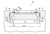
- FIG. 2 is a partial cross-sectional view schematically showing the lens periphery of the camera of the second embodiment.
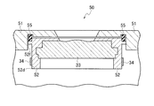
- FIG. 3 is a partial cross-sectional view schematically showing the lens periphery of the camera of the third embodiment.
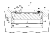
- FIG. 4 is a partial cross-sectional view schematically showing the lens periphery of the camera of the fourth embodiment.
- FIG. 5 is a partial cross-sectional view schematically showing the lens periphery of the camera of the fifth embodiment.
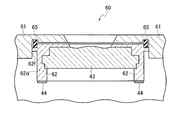
- FIG. 6 is a partial cross-sectional view schematically showing the lens periphery of the camera of the sixth embodiment.
- FIG. 7 is a partial cross-sectional view schematically showing the lens periphery of the camera of the seventh embodiment.
- the cameras according to the first to seventh embodiments will be described with reference to FIGS.
- the cameras of the first to seventh embodiments are, for example, infrared cameras that are used outdoors or outside the vehicle. Specifically, it is an in-vehicle night vision camera for detecting a person or a vehicle at night.
- the cameras of the first to seventh embodiments are identical in that the heater for heating the lens periphery is fixed to the lens barrel, and the positions where the heaters are fixed are different. That is, the cameras of the first to seventh embodiments are characterized by the lens periphery. Therefore, the cameras of the first to seventh embodiments will be described mainly with respect to the lens periphery.
- FIG. 1 is a partial cross-sectional view schematically showing a lens peripheral portion of the camera of the first embodiment.
- the camera 10 includes a camera housing 11, a lens barrel 12, a lens 13, a heater 14, and a waterproofing member 15.
- the camera casing 11 is made of a metal material or a resin material.
- An opening 11 a is formed in the camera housing 11.
- the opening 11a is formed so that the opening diameter increases toward the outside (upward in FIG. 1).
- the lens barrel 12 is stored in the camera casing 11.
- the lens barrel 12 is made of a metal material such as aluminum. Note that the vertical direction in FIG. 1 is the optical axis direction of the lens barrel 12 and the lens 13.
- An opening 12b is formed on the end surface (the upper end surface in FIG. 1) 12a of the lens barrel 12 in the optical axis direction.
- the opening 12b is formed so that the opening diameter increases toward the outside.
- the opening 11a of the camera casing 11 and the opening 12b of the lens barrel 12 are aligned.
- the opening 11a and the opening 12b function as shooting windows.
- the lens 13 is fixed to the inside of the lens barrel 12, specifically to the inner peripheral surface 12c on the opening 12b side of the lens barrel 12.
- the surface 13a (the upper surface in FIG. 1) 13a on the opening 12b side of the lens 13 has an uneven shape close to a plane.
- the central portion 13a1 is formed in a convex shape toward the outside, and the outer peripheral portion 13a2 positioned around the central portion 13a1 is formed in a concave shape.
- the lens 13 is made of a transparent material such as glass or resin.
- the heater 14 has a ring shape.
- the heater 14 is fixed to the end surface 12a of the lens barrel 12 so as to surround the opening 12b. By heating the lens barrel 12 with the heater 14, it is possible to remove rain or snow attached to the lens 13 or the like, or to suppress the attachment of rain or snow.
- the waterproofing member 15 has a ring shape.
- the waterproof member 15 is disposed concentrically with the heater 14 on the end surface 12 a on the opening 12 b side of the heater 14.
- the waterproofing member 15 is disposed in the gap between the lens barrel 12 and the camera housing 11.
- the waterproofing member 15 is in close contact with the end surface 12 a of the lens barrel 12 and the camera housing 11.
- a waterproof rubber can be used as the waterproof member 15, for example, a waterproof rubber can be used.
- the waterproof member 15 can prevent the camera casing 11 from entering the interior. it can. Therefore, the inside of the heater 14 and the camera housing 11 is protected by the waterproof member 15.
- the rain or melted snow attached to the lens 13 and the like is caused by the uneven shape of the lens 13 from the central portion 13a1 of the lens 13. It becomes easy to flow toward the outer peripheral part 13a2.
- the contact angle between the outer peripheral portion 13a2 and the lens barrel 12 is larger than that of a flat surface.
- the lens barrel 12 and the camera casing 11 are formed such that the opening diameters of the opening 12b and the opening 11a increase toward the outside.
- the rain or melted snow that has moved to the outer peripheral portion 13 a 2 of the lens 13 is more likely to flow to the outside through the lens barrel 12 and the camera housing 11. Therefore, it is possible to easily remove rain or snow attached to the lens 13 or the like, or to easily prevent rain or snow from attaching.
- the influence of rain or snow can be reduced with a single camera. Therefore, the degree of freedom of installation location can be improved at a lower price than in the past.
- FIG. 2 is a partial cross-sectional view schematically showing the lens periphery of the camera of the second embodiment.
- the camera 20 of the second embodiment is different from the camera 10 of the first embodiment in that the heater is fixed to the outer peripheral surface of the lens barrel.
- the camera 20 includes a camera housing 21, a lens barrel 22, a lens 23, a heater 24, and a waterproofing member 25.
- the camera casing 21 is made of a metal material or a resin material.
- An opening 21 a is formed in the camera housing 21.
- the opening 21a has the same shape as the opening 11a of the camera 10 (see FIG. 1) of the first embodiment.
- the lens barrel 22 is stored in the camera casing 21.
- the lens barrel 22 is made of a metal material such as aluminum. Note that the vertical direction in FIG. 2 is the optical axis direction of the lens barrel 22 and the lens 23.
- An opening 22b is formed on the end surface of the lens barrel 22 in the optical axis direction (upper end surface in FIG. 2) 22a.
- the opening 22b has the same shape as the opening 12b of the camera 10 of the first embodiment.
- the opening 22b of the lens barrel 22 and the opening 21a of the camera casing 21 are aligned.
- the opening 22b and the opening 21a function as a shooting window.
- Ribs 22 e are formed on the outer peripheral surface 22 d of the lens barrel 22.
- the lens 23 has the same shape as the lens 13 of the camera 10 of the first embodiment and is formed of the same material.
- the lens 23 is fixed to the inside of the lens barrel 22, specifically, to the inner peripheral surface 22 c on the opening 22 b side of the lens barrel 22.
- the heater 24 has a strip shape.
- the heater 24 is fixed so as to go around the outer peripheral surface 22d in the vicinity of the end surface 22a of the lens barrel 22. By heating the lens barrel 22 with the heater 24, it is possible to remove rain or snow adhering to the lens 23 or the like, or to suppress the attachment of rain or snow.
- the waterproofing member 25 has the same shape as the waterproofing member 15 of the camera 10 of the first embodiment, and is formed of the same material.
- the waterproofing member 25 is disposed at the same position as the waterproofing member 15.
- the waterproof member 25 is in close contact with the end surface 22 a of the lens barrel 22 and the camera housing 21.
- the waterproof member 25 can prevent the camera casing 21 from entering the interior. it can. Therefore, the inside of the heater 24 and the camera housing 21 is protected by the waterproof member 25.
- the rib 22e formed on the lens barrel 22 has a positioning function for easily positioning and fixing the heater 24 to the outer peripheral surface 22d of the lens barrel 22.
- the rib 22e is formed to be higher than the thickness of the heater 24.
- the rib 22e has a function of preventing the heater 24 from coming into contact with the camera casing 21 and being damaged.
- the influence of rain or snow can be reduced with a single camera. Therefore, the degree of freedom of installation location can be improved at a lower price than in the past.
- a heater 14 and a waterproof member 15 are disposed on an end surface 12 a of the lens barrel 12.
- the waterproof member 25 is arranged on the end surface 22a of the lens barrel 22. Therefore, the outer diameter R22 of the lens barrel 22 of the camera 20 of the second embodiment can be made smaller than the outer diameter R12 of the lens barrel 12 of the camera 10 of the first embodiment.
- the camera 20 of the second embodiment can be made smaller than the camera 10 of the first embodiment, the degree of freedom of the installation location can be further improved.
- FIG. 3 is a partial cross-sectional view schematically showing the lens periphery of the camera of the third embodiment.
- the camera 30 of the third embodiment is different from the camera 20 of the second embodiment in that the heater is fixed to the outer peripheral surface at a position away from the end surface of the lens barrel.
- the camera 30 includes a camera housing 31, a lens barrel 32, a lens 33, a heater 34, and a waterproofing member 35.
- the camera casing 31 is made of a metal material or a resin material.
- An opening 31 a is formed in the camera housing 31.
- the opening 31a has the same shape as the opening 21a of the camera 20 (see FIG. 2) of the second embodiment.
- the lens barrel 32 is stored in the camera casing 31.
- the lens barrel 32 is made of a metal material such as aluminum. Note that the vertical direction in FIG. 3 is the optical axis direction of the lens barrel 32 and the lens 33.
- An opening 32b is formed on the end surface of the lens barrel 32 in the optical axis direction (upper end surface in FIG. 3) 32a.
- the opening 32b has the same shape as the opening 22b of the camera 20 of the second embodiment.
- the opening 32b of the lens barrel 32 and the opening 31a of the camera casing 31 are aligned.
- the opening 32b and the opening 31a function as a window for photographing.
- the lens 33 has the same shape as the lens 23 of the camera 20 of the second embodiment and is made of the same material.
- the lens 33 is fixed to the inside of the lens barrel 32, specifically, to the inner peripheral surface 32 c on the opening 32 b side of the lens barrel 32.
- the heater 34 has the same shape as the heater 24 of the camera 20 of the second embodiment.
- the heater 34 is fixed at a position away from the end surface 32a of the lens barrel 32 so as to go around the outer peripheral surface 32d. By heating the lens barrel 32 with the heater 34, it is possible to remove rain or snow adhering to the lens 33 or the like, or to suppress the attachment of rain or snow.
- the waterproofing member 35 has the same shape as the waterproofing member 25 of the camera 20 of the second embodiment, and is formed of the same material.
- the waterproof member 35 is disposed at the same position as the waterproof member 25.
- the waterproof member 35 is in close contact with the end surface 32 a of the lens barrel 32 and the camera housing 31.
- the waterproof member 35 can prevent the camera casing 31 from entering the interior. it can. Therefore, the inside of the heater 34 and the camera casing 31 is protected by the waterproof member 35.
- the influence of rain or snow can be reduced with a single camera. Therefore, the degree of freedom of installation location can be improved at a lower price than in the past.
- the heater 24 is fixed in the vicinity of the end surface 22 a of the lens barrel 22.
- the lens barrel 22 is formed with ribs 22e for preventing the heater 24 from coming into contact with the camera casing 21 and being damaged.
- the heater 34 is fixed at a position away from the end surface 32 a of the lens barrel 32. Therefore, since the heater 34 does not contact the camera housing 31, it is not necessary to form the rib 22e. Therefore, the outer diameter R32 of the lens barrel 32 of the camera 30 of the third embodiment can be made smaller than the outer diameter R22 of the lens barrel 22 of the camera 20 of the second embodiment. Therefore, since the camera 30 of the third embodiment can be made smaller than the camera 20 of the second embodiment, the degree of freedom of installation location can be further improved.
- FIG. 4 is a partial cross-sectional view schematically showing the lens periphery of the camera of the fourth embodiment.
- the camera 40 of the fourth embodiment is different from the camera 10 of the first embodiment in that the heater is fixed to the other end surface of the lens barrel.
- the camera 40 includes a camera housing 41, a lens barrel 42, a lens 43, a heater 44, and a waterproof member 45.
- the camera casing 41 is made of a metal material or a resin material.
- An opening 41 a is formed in the camera housing 41.
- the opening 41a has the same shape as the opening 11a of the camera 10 (see FIG. 1) of the first embodiment.
- the lens barrel 42 is stored in the camera casing 41.
- the lens barrel 42 is made of a metal material such as aluminum. Note that the vertical direction in FIG. 4 is the optical axis direction of the lens barrel 42 and the lens 43.
- An opening 42b is formed on one end face (upper end face in FIG. 4) 42a side of the lens barrel 42 in the optical axis direction.
- the opening 42b has the same shape as the opening 12b of the camera 10 of the first embodiment.
- the opening 42b of the lens barrel 42 and the opening 41a of the camera housing 41 are aligned.
- the opening 42b and the opening 41a function as a shooting window.
- the lens 43 has the same shape as the lens 13 of the camera 10 of the first embodiment, and is formed of the same material.
- the lens 43 is fixed to the inside of the lens barrel 42, specifically, to the inner peripheral surface 42 c on the opening 42 b side of the lens barrel 42.
- the heater 44 has a ring shape.
- the heater 44 is fixed to the other end surface (the lower end surface in FIG. 4) 42f of the lens barrel 42 in the optical axis direction. That is, the heater 44 is fixed to the end surface opposite to the end surface 12a to which the heater 14 of the camera 10 of the first embodiment is fixed.
- the waterproofing member 45 has the same shape as the waterproofing member 15 of the camera 10 of the first embodiment and is formed of the same material.
- the waterproof member 45 is disposed at the same position as the waterproof member 15.
- the waterproof member 45 is in close contact with the end surface 42 a of the lens barrel 42 and the camera housing 41.
- the waterproof member 45 can prevent the camera housing 41 from entering the camera housing 41. it can. Therefore, the inside of the heater 44 and the camera housing 41 is protected by the waterproof member 45.
- the influence of rain or snow can be reduced with the camera alone. Therefore, the degree of freedom of installation location can be improved at a lower price than in the past.
- the heater 34 is fixed to the outer peripheral surface 32 d of the lens barrel 32.
- a sufficient range in which the heater 34 and the camera casing 31 do not contact each other cannot be secured.
- it is necessary to form a rib similar to the rib 22e of the camera 20 of the second embodiment on the outer peripheral surface 32d. is there.
- the heater 44 is fixed to the end face 42f of the lens barrel 42. Therefore, it is not necessary to form a rib on the outer peripheral surface 42d. Therefore, the degree of freedom in design can be improved.
- FIG. 5 is a partial cross-sectional view schematically showing the lens periphery of the camera of the fifth embodiment.
- the camera of the fifth embodiment is the same as the camera 30 of the third embodiment in the position of the heater fixed to the lens barrel and the position of the waterproof member.
- the same components as those of the camera 30 of the third embodiment are denoted by the same reference numerals.
- the camera 50 includes a camera housing 51, a lens barrel 52, a lens 33, a heater 34, and a waterproofing member 55.
- Ribs 52 f are formed on the outer peripheral surface 52 d of the lens barrel 52.
- the rib 52f has a ring shape.
- the rib 52f has a positioning function for easily positioning and fixing the waterproof member 55 to the lens barrel 52.
- the rib 52f is formed to be higher than the width of the waterproofing member 55.
- the waterproofing member 55 has a ring shape.
- a waterproof rubber can be used as the waterproof member 55.
- the waterproof member 55 is in close contact with the rib 52f and the camera casing 51.
- the entry into the camera 50 can be prevented by the waterproof member 54. Accordingly, the inside of the heater 34 and the camera 50 is protected by the waterproof member 54.
- FIG. 6 is a partial cross-sectional view schematically showing the lens periphery of the camera of the sixth embodiment.
- the camera of the sixth embodiment is the same as the camera 40 of the fourth embodiment in the position of the heater fixed to the lens barrel and the position of the waterproof member.
- the same components as those of the camera 40 of the fourth embodiment are denoted by the same reference numerals.
- the camera 60 includes a camera housing 61, a lens barrel 62, a lens 43, a heater 44, and a waterproof member 65.
- Ribs 62 f are formed on the outer peripheral surface 62 d of the lens barrel 62.
- the rib 62f has a ring shape.
- the rib 62f has a positioning function for easily positioning and fixing the waterproof member 65 to the lens barrel 62.
- the rib 62f is formed to be higher than the width of the waterproofing member 65.
- the waterproofing member 65 has a ring shape.
- a waterproof rubber can be used as the waterproof member 65.
- the waterproofing member 65 is in close contact with the rib 62f and the camera housing 61. When rain or melted snow adhering to the lens 43 or the like enters the gap between the camera housing 61 and the lens barrel 62, the waterproof member 65 can prevent the camera 60 from entering the inside. Accordingly, the inside of the heater 44 and the camera 60 is protected by the waterproof member 65.
- FIG. 7 is a partial cross-sectional view schematically showing the lens periphery of the camera of the seventh embodiment.
- the camera of the seventh embodiment differs from the camera 40 of the fourth embodiment in the shape of the lens barrel.
- the same components as those of the camera 40 of the fourth embodiment are denoted by the same reference numerals.
- the camera 70 includes a camera housing 41, a lens barrel 72, a plurality of lenses 43, 73a, 73b, a heater 44, and a waterproofing member 45.
- a plurality of lenses 43, 73a, 73b may be used. Therefore, if the heater 44 is fixed to the end surface (the lower end surface in FIG. 7) 72b of the lens barrel 72, the distance between the heater 44 and the lens 43 becomes long. Therefore, the power supplied to the heater 44 is increased.
- a stepped portion 72g is formed at a position near the lens 43 of the lens barrel 72.
- the cameras (10, 20, 30, 40, 50, 60, 70) of the first to seventh embodiments have lens barrels (12, 22, 32, 42, 52, 62, 72) and heaters (14, 24). , 34, 44) are fixed.
- the lens barrel is made of a metal material. Therefore, the heat generated by the heater can be efficiently transmitted to the lens via the lens barrel. Thereby, it is possible to efficiently remove rain or snow attached to the lens or the like, or to suppress the attachment of rain or snow.
- the influence of rain or snow can be reduced by the camera alone. Therefore, the freedom degree of an installation place can be improved at a lower price than before.
- the waterproof member prevents rain or snow adhering to the lens and the like from entering the camera through the gap between the camera housing and the lens barrel. , 35, 45, 55, 65). Therefore, the inside of the heater and the camera is protected by the waterproof member.
- the cameras (10, 20) of the first and second embodiments have a lens ( 13 and 23). Therefore, the heat generated by the heater can be more efficiently transmitted to the lens. Therefore, power consumption for heating the heater can be suppressed.
- the cameras (20, 30, 40) of the second to fourth embodiments have end faces (22a) on which the waterproof members (25, 35, 45) are arranged as compared with the camera (10) of the first embodiment.
- 32a, 42a) heaters (24, 34, 44) are arranged at different positions. Therefore, the outer diameter (R22, R32, R42) of the lens barrel (22, 32, 42) can be reduced. Thereby, the freedom degree of an installation place can further be improved.
- ⁇ Design may increase the opening diameter of the camera casing and lens barrel opening.
- the cameras (30, 40) of the third and fourth embodiments it is difficult to secure a space for arranging the waterproofing members (35, 45) on the end surfaces (32a, 42a).
- ribs (52f, 62f) are formed on the outer peripheral surfaces (52d, 62d) of the lens barrel (52, 62), and the ribs are waterproof.
- the various shapes of the lens barrel, the lens, the camera housing, the heater, and the waterproof member are not limited to the various shapes of the first to fourth embodiments, and are appropriately designed according to the design specifications. Is possible.
- the present invention can be used for a camera used outside the vehicle or outdoors such as an infrared camera.
Landscapes
- Physics & Mathematics (AREA)
- General Physics & Mathematics (AREA)
- Engineering & Computer Science (AREA)
- Multimedia (AREA)
- Signal Processing (AREA)
- Optics & Photonics (AREA)
- Structure And Mechanism Of Cameras (AREA)
- Lens Barrels (AREA)
- Studio Devices (AREA)
- Camera Bodies And Camera Details Or Accessories (AREA)
Abstract
カメラ(10)は、カメラ筐体(11)、レンズ鏡筒(12)、レンズ(13)、ヒータ(14)、及び、防水用部材(15)を備える。レンズ鏡筒(12)はカメラ筐体(11)に格納されている。レンズ(13)はレンズ鏡筒(12)の内部に固定されている。ヒータ(14)はレンズ鏡筒(12)に固定され、レンズ(13)をレンズ鏡筒(12)を介して加熱する。防水用部材(15)はレンズ鏡筒(12)とカメラ筐体(11)との間隙に配置され、レンズ鏡筒(12)及びカメラ筐体(11)と密着している。
Description
本開示は、赤外カメラ等の車外または屋外で使用されるカメラに関する。
赤外カメラ等の屋外または車外で使用されるカメラでは、雨または雪などがレンズに付着して撮影が困難になる場合がある。そのため、雨または雪などによる影響を低減させることが重要である。
特許文献1には、カメラをカメラケースに格納することで、雨または雪などによる影響を低減させることが記載されている。また、カメラケースの撮影用窓の周辺にヒータを配置することで、窓に付着した雪を溶かすことが記載されている。
しかしながら、カメラケースはカメラを格納するための大きさが必要である。そのため、全体的に大きくなってしまうので、カメラの設置場所が制限される場合がある。また、カメラの他にカメラケースが必要になるため価格が高くなってしまう。
実施形態は、従来よりも、設置場所の自由度を向上させ、低価格で、雨または雪などによる影響を低減させることができるカメラを提供することを目的とする。
実施形態の一態様によれば、カメラ筐体と、カメラ筐体に格納されているレンズ鏡筒と、レンズ鏡筒の内部に固定されているレンズと、レンズ鏡筒に固定され、レンズをレンズ鏡筒を介して加熱するヒータと、レンズ鏡筒とカメラ筐体との間隙に配置され、レンズ鏡筒及びカメラ筐体に密着する防水用部材とを備えることを特徴とするカメラが提供される。
実施形態のカメラによれば、従来よりも、設置場所の自由度を向上させ、低価格で、雨または雪などによる影響を低減させることができる。
図1~図7を用いて第1実施形態~第7実施形態のカメラを説明する。第1実施形態~第7実施形態のカメラは、例えば、屋外または車外で使用される赤外カメラである。具体的には夜間に人または車を検知するための車載用ナイトビジョンカメラである。第1実施形態~第7実施形態のカメラは、レンズ周辺部を加熱するためのヒータがレンズ鏡筒に固定されている点で一致し、固定されている位置が相違する。即ち、第1実施形態~第7実施形態のカメラはレンズ周辺部に特徴を有する。そこで、第1実施形態~第7実施形態のカメラについて、レンズ周辺部を主体に説明する。
[第1実施形態]
図1を用いて第1実施形態のカメラを説明する。図1は第1実施形態のカメラのレンズ周辺部を模式的に示す部分断面図である。
図1を用いて第1実施形態のカメラを説明する。図1は第1実施形態のカメラのレンズ周辺部を模式的に示す部分断面図である。
カメラ10は、カメラ筐体11、レンズ鏡筒12、レンズ13、ヒータ14、及び、防水用部材15を備える。
カメラ筐体11は金属材料または樹脂材料で形成されている。カメラ筐体11には開口部11aが形成されている。開口部11aは外部(図1における上方向)に向かって開口径が大きくなるように形成されている。
レンズ鏡筒12はカメラ筐体11に格納されている。レンズ鏡筒12はアルミニウム等の金属材料で形成されている。なお、図1における上下方向がレンズ鏡筒12及びレンズ13の光軸方向である。
レンズ鏡筒12の光軸方向の端面(図1における上側の端面)12a側には開口部12bが形成されている。開口部12bは外部に向かって開口径が大きくなるように形成されている。
カメラ筐体11の開口部11aとレンズ鏡筒12の開口部12bとは位置合わせされている。開口部11a及び開口部12bは撮影用の窓として機能する。
レンズ13は、レンズ鏡筒12の内部、具体的にはレンズ鏡筒12の開口部12b側の内周面12cに固定されている。レンズ13の開口部12b側の面(図1における上側の面)13aは平面に近い凹凸形状を有する。具体的には開口部12bに対して、中心部13a1が外部に向かって凸状に形成され、中心部13a1の周囲に位置する外周部13a2が凹状に形成されている。レンズ13はガラスまたは樹脂等の透明材料で形成されている。
ヒータ14はリング形状を有する。ヒータ14はレンズ鏡筒12の端面12aに、開口部12bを囲うように固定されている。ヒータ14でレンズ鏡筒12を加熱することにより、レンズ13等に付着した雨または雪を除去したり、雨または雪の付着を抑制したりすることができる。
防水用部材15はリング形状を有する。防水用部材15はヒータ14よりも開口部12b側の端面12aに、ヒータ14と同心円上に配置されている。防水用部材15はレンズ鏡筒12とカメラ筐体11との間隙に配置されている。防水用部材15はレンズ鏡筒12の端面12a及びカメラ筐体11に密着している。防水用部材15として例えば防水用ゴムを用いることができる。
レンズ13等に付着した雨または溶けた雪などがカメラ筐体11とレンズ鏡筒12との間隙に侵入した場合に、カメラ筐体11の内部への侵入を防水用部材15で防止することができる。従って、ヒータ14及びカメラ筐体11の内部は防水用部材15により保護されている。
カメラ10が、レンズ13の光軸が地面と水平になるように設置されている場合、レンズ13等に付着した雨または溶けた雪は、レンズ13の凹凸形状により、レンズ13の中心部13a1から外周部13a2に向かって流れやすくなる。
レンズ13は外周部13a2が凹状になっているため、外周部13a2とレンズ鏡筒12との接触角が平坦な面と比較して大きくなっている。また、レンズ鏡筒12及びカメラ筐体11は、開口部12b及び開口部11aの開口径が外部に向かって大きくなるように形成されている。
そのため、レンズ13の外周部13a2へ移動した雨または溶けた雪は、さらにレンズ鏡筒12及びカメラ筐体11を伝って外部に流れやすくなる。従って、レンズ13等に付着した雨または雪を容易に除去したり、雨または雪の付着を容易に抑制したりすることができる。
第1実施形態のカメラ10によれば、カメラ単体で雨または雪などによる影響を低減させることができる。従って、従来よりも、低価格で、設置場所の自由度を向上させることができる。
[第2実施形態]
図2を用いて第2実施形態のカメラを説明する。図2は第2実施形態のカメラのレンズ周辺部を模式的に示す部分断面図である。
図2を用いて第2実施形態のカメラを説明する。図2は第2実施形態のカメラのレンズ周辺部を模式的に示す部分断面図である。
第2実施形態のカメラ20は、第1実施形態のカメラ10と比較して、ヒータがレンズ鏡筒の外周面に固定されている点で相違する。
カメラ20は、カメラ筐体21、レンズ鏡筒22、レンズ23、ヒータ24、及び、防水用部材25を備える。
カメラ筐体21は金属材料または樹脂材料で形成されている。カメラ筐体21には開口部21aが形成されている。開口部21aは第1実施形態のカメラ10(図1参照)の開口部11aと同じ形状を有する。
レンズ鏡筒22はカメラ筐体21に格納されている。レンズ鏡筒22はアルミニウム等の金属材料で形成されている。なお、図2における上下方向がレンズ鏡筒22及びレンズ23の光軸方向である。
レンズ鏡筒22の光軸方向の端面(図2における上側の端面)22a側には開口部22bが形成されている。開口部22bは第1実施形態のカメラ10の開口部12bと同じ形状を有する。
レンズ鏡筒22の開口部22bとカメラ筐体21の開口部21aとは位置合わせされている。開口部22b及び開口部21aは撮影用の窓として機能する。
レンズ鏡筒22の外周面22dにはリブ22eが形成されている。
レンズ23は、第1実施形態のカメラ10のレンズ13と同じ形状を有し、同じ材料で形成されている。レンズ23はレンズ鏡筒22の内部、具体的にはレンズ鏡筒22の開口部22b側の内周面22cに固定されている。
ヒータ24は短冊形状を有する。ヒータ24はレンズ鏡筒22の端面22aの近傍で外周面22dを一周するように固定されている。ヒータ24でレンズ鏡筒22を加熱することにより、レンズ23等に付着した雨または雪を除去したり、雨または雪の付着を抑制したりすることができる。
防水用部材25は、第1実施形態のカメラ10の防水用部材15と同じ形状を有し、同じ材料で形成されている。防水用部材25は防水用部材15と同様の位置に配置されている。防水用部材25はレンズ鏡筒22の端面22a及びカメラ筐体21に密着している。
レンズ23等に付着した雨または溶けた雪などがカメラ筐体21とレンズ鏡筒22との間隙に侵入した場合に、カメラ筐体21の内部への侵入を防水用部材25で防止することができる。従って、ヒータ24及びカメラ筐体21の内部は防水用部材25により保護されている。
レンズ鏡筒22に形成されているリブ22eは、ヒータ24をレンズ鏡筒22の外周面22dに容易に位置決めして固定するための位置決め機能を有している。リブ22eは、ヒータ24の厚さよりも高くなるように形成されている。リブ22eは、ヒータ24がカメラ筐体21と接触して破損してしまうことを防止する機能を有している。
カメラ20がレンズ23の光軸が地面と水平になるように設置されている場合、第1実施形態のカメラ10と同様の理由により、レンズ23等に付着した雨または雪をヒータ24により容易に除去したり、雨または雪の付着を容易に抑制したりすることができる。
第2実施形態のカメラ20によれば、カメラ単体で雨または雪などによる影響を低減させることができる。従って、従来よりも、低価格で、設置場所の自由度を向上させることができる。
第1実施形態のカメラ10はレンズ鏡筒12の端面12aにヒータ14と防水用部材15とが配置されている。それに対して、第2実施形態のカメラ20はレンズ鏡筒22の端面22aには防水用部材25のみが配置されている。そのため、第2実施形態のカメラ20のレンズ鏡筒22の外径R22を、第1実施形態のカメラ10のレンズ鏡筒12の外径R12よりも小さくすることができる。
従って、第2実施形態のカメラ20を第1実施形態のカメラ10よりも小さくすることができるので、設置場所の自由度をさらに向上させることができる。
[第3実施形態]
図3を用いて第3実施形態のカメラを説明する。図3は第3実施形態のカメラのレンズ周辺部を模式的に示す部分断面図である。
図3を用いて第3実施形態のカメラを説明する。図3は第3実施形態のカメラのレンズ周辺部を模式的に示す部分断面図である。
第3実施形態のカメラ30は、第2実施形態のカメラ20と比較して、ヒータがレンズ鏡筒の端面から離れた位置で外周面に固定されている点で相違する。
カメラ30は、カメラ筐体31、レンズ鏡筒32、レンズ33、ヒータ34、及び、防水用部材35を備える。
カメラ筐体31は金属材料または樹脂材料で形成されている。カメラ筐体31には開口部31aが形成されている。開口部31aは第2実施形態のカメラ20(図2参照)の開口部21aと同じ形状を有する。
レンズ鏡筒32はカメラ筐体31に格納されている。レンズ鏡筒32はアルミニウム等の金属材料で形成されている。なお、図3における上下方向がレンズ鏡筒32及びレンズ33の光軸方向である。
レンズ鏡筒32の光軸方向の端面(図3における上側の端面)32a側には開口部32bが形成されている。開口部32bは第2実施形態のカメラ20の開口部22bと同じ形状を有する。
レンズ鏡筒32の開口部32bとカメラ筐体31の開口部31aとは位置合わせされている。開口部32b及び開口部31aは撮影用の窓として機能する。
レンズ33は、第2実施形態のカメラ20のレンズ23と同じ形状を有し、同じ材料で形成されている。レンズ33はレンズ鏡筒32の内部、具体的にはレンズ鏡筒32の開口部32b側の内周面32cに固定されている。
ヒータ34は第2実施形態のカメラ20のヒータ24と同様の形状を有する。ヒータ34はレンズ鏡筒32の端面32aから離れた位置に外周面32dを一周するように固定されている。ヒータ34でレンズ鏡筒32を加熱することにより、レンズ33等に付着した雨または雪を除去したり、雨または雪の付着を抑制したりすることができる。
防水用部材35は、第2実施形態のカメラ20の防水用部材25と同じ形状を有し、同じ材料で形成されている。防水用部材35は防水用部材25と同様の位置に配置されている。防水用部材35はレンズ鏡筒32の端面32a及びカメラ筐体31に密着している。
レンズ33等に付着した雨または溶けた雪などがカメラ筐体31とレンズ鏡筒32との間隙に侵入した場合に、カメラ筐体31の内部への侵入を防水用部材35で防止することができる。従って、ヒータ34及びカメラ筐体31の内部は防水用部材35により保護されている。
カメラ30がレンズ33の光軸が地面と水平になるように設置されている場合、第1実施形態のカメラ10と同様の理由により、レンズ33等に付着した雨または雪をヒータ34により容易に除去したり、雨または雪の付着を容易に抑制したりすることができる。
第3実施形態のカメラ30によれば、カメラ単体で雨または雪などによる影響を低減させることができる。従って、従来よりも、低価格で、設置場所の自由度を向上させることができる。
第2実施形態のカメラ20はヒータ24がレンズ鏡筒22の端面22aの近傍に固定されている。そのため、レンズ鏡筒22には、ヒータ24がカメラ筐体21と接触して破損することを防止するためのリブ22eが形成されている。
それに対して、第3実施形態のカメラ30はヒータ34がレンズ鏡筒32の端面32aから離れた位置に固定されている。そのため、ヒータ34がカメラ筐体31と接触しないので、リブ22eを形成する必要がない。従って、第3実施形態のカメラ30のレンズ鏡筒32の外径R32を、第2実施形態のカメラ20のレンズ鏡筒22の外径R22よりも小さくすることができる。よって、第3実施形態のカメラ30を第2実施形態のカメラ20よりも小さくすることができるので、設置場所の自由度をさらに向上させることができる。
[第4実施形態]
図4を用いて第4実施形態のカメラを説明する。図4は第4実施形態のカメラのレンズ周辺部を模式的に示す部分断面図である。
図4を用いて第4実施形態のカメラを説明する。図4は第4実施形態のカメラのレンズ周辺部を模式的に示す部分断面図である。
第4実施形態のカメラ40は、第1実施形態のカメラ10と比較して、ヒータがレンズ鏡筒の他方の端面に固定されている点で相違する。
カメラ40は、カメラ筐体41、レンズ鏡筒42、レンズ43、ヒータ44、及び、防水用部材45を備える。
カメラ筐体41は金属材料または樹脂材料で形成されている。カメラ筐体41には開口部41aが形成されている。開口部41aは第1実施形態のカメラ10(図1参照)の開口部11aと同じ形状を有する。
レンズ鏡筒42はカメラ筐体41に格納されている。レンズ鏡筒42はアルミニウム等の金属材料で形成されている。なお、図4における上下方向がレンズ鏡筒42及びレンズ43の光軸方向である。
レンズ鏡筒42の光軸方向の一方の端面(図4における上側の端面)42a側には開口部42bが形成されている。開口部42bは第1実施形態のカメラ10の開口部12bと同じ形状を有する。
レンズ鏡筒42の開口部42bとカメラ筐体41の開口部41aとは位置合わせされている。開口部42b及び開口部41aは撮影用の窓として機能する。
レンズ43は、第1実施形態のカメラ10のレンズ13と同じ形状を有し、同じ材料で形成されている。レンズ43はレンズ鏡筒42の内部、具体的にはレンズ鏡筒42の開口部42b側の内周面42cに固定されている。
ヒータ44はリング形状を有する。ヒータ44はレンズ鏡筒42の光軸方向の他方の端面(図4における下側の端面)42fに固定されている。即ち、ヒータ44は、第1実施形態のカメラ10のヒータ14が固定されている端面12aとは反対側の端面に固定されている。ヒータ44でレンズ鏡筒42を加熱することにより、レンズ43等に付着した雨または雪を除去したり、雨または雪の付着を抑制したりすることができる。
防水用部材45は、第1実施形態のカメラ10の防水用部材15と同じ形状を有し、同じ材料で形成されている。防水用部材45は防水用部材15と同様の位置に配置されている。防水用部材45はレンズ鏡筒42の端面42a及びカメラ筐体41に密着している。
レンズ43等に付着した雨または溶けた雪などがカメラ筐体41とレンズ鏡筒42との間隙に侵入した場合に、カメラ筐体41の内部への侵入を防水用部材45で防止することができる。従って、ヒータ44及びカメラ筐体41の内部は防水用部材45により保護されている。
カメラ40がレンズ43の光軸が地面と水平になるように設置されている場合、第1実施形態のカメラ10と同様の理由により、レンズ43等に付着した雨または雪をヒータ44により容易に除去したり、雨または雪の付着を容易に抑制したりすることができる。
第4実施形態のカメラ40によれば、カメラ単体で雨または雪などによる影響を低減させることができる。従って、従来よりも、低価格で、設置場所の自由度を向上させることができる。
第3実施形態のカメラ30はヒータ34がレンズ鏡筒32の外周面32dに固定されている。設計上、ヒータ34とカメラ筐体31とが接触しない範囲を十分に確保できない場合がある。このような場合、ヒータ34がカメラ筐体31と接触して破損してしまうことを防止するために、第2実施形態のカメラ20のリブ22eと同様のリブを外周面32dに形成する必要がある。
それに対して、第4実施形態のカメラ40はヒータ44がレンズ鏡筒42の端面42fに固定されている。そのため、外周面42dにリブを形成する必要がない。従って、設計の自由度を向上させることができる。
[第5実施形態]
図5を用いて第5実施形態のカメラを説明する。図5は第5実施形態のカメラのレンズ周辺部を模式的に示す部分断面図である。第5実施形態のカメラは第3実施形態のカメラ30に対して、レンズ鏡筒に固定されているヒータの位置が同じであり、防水用部材の位置が異なる。なお、説明をわかりやすくするために、第3実施形態のカメラ30と同じ構成部には同じ符号を付す。
図5を用いて第5実施形態のカメラを説明する。図5は第5実施形態のカメラのレンズ周辺部を模式的に示す部分断面図である。第5実施形態のカメラは第3実施形態のカメラ30に対して、レンズ鏡筒に固定されているヒータの位置が同じであり、防水用部材の位置が異なる。なお、説明をわかりやすくするために、第3実施形態のカメラ30と同じ構成部には同じ符号を付す。
カメラ50は、カメラ筐体51、レンズ鏡筒52、レンズ33、ヒータ34、及び、防水用部材55を備える。
レンズ鏡筒52の外周面52dにはリブ52fが形成されている。リブ52fはリング形状を有する。リブ52fは、防水用部材55をレンズ鏡筒52に容易に位置決めして固定するための位置決め機能を有している。リブ52fは、防水用部材55の幅よりも高くなるように形成されている。
防水用部材55はリング形状を有する。防水用部材55として例えば防水用ゴムを用いることができる。防水用部材55はリブ52f及びカメラ筐体51に密着している。レンズ33等に付着した雨または溶けた雪などがカメラ筐体51とレンズ鏡筒52との間隙に侵入した場合に、カメラ50の内部への侵入を防水用部材54で防止することができる。従って、ヒータ34及びカメラ50の内部は防水用部材54により保護される。
[第6実施形態]
図6を用いて第6実施形態のカメラを説明する。図6は第6実施形態のカメラのレンズ周辺部を模式的に示す部分断面図である。第6実施形態のカメラは第4実施形態のカメラ40に対して、レンズ鏡筒に固定されているヒータ位置が同じであり、防水用部材の位置が異なる。なお、説明をわかりやすくするために、第4実施形態のカメラ40と同じ構成部には同じ符号を付す。
図6を用いて第6実施形態のカメラを説明する。図6は第6実施形態のカメラのレンズ周辺部を模式的に示す部分断面図である。第6実施形態のカメラは第4実施形態のカメラ40に対して、レンズ鏡筒に固定されているヒータ位置が同じであり、防水用部材の位置が異なる。なお、説明をわかりやすくするために、第4実施形態のカメラ40と同じ構成部には同じ符号を付す。
カメラ60は、カメラ筐体61、レンズ鏡筒62、レンズ43、ヒータ44、及び、防水用部材65を備える。
レンズ鏡筒62の外周面62dにはリブ62fが形成されている。リブ62fはリング形状を有する。リブ62fは、防水用部材65をレンズ鏡筒62に容易に位置決めして固定するための位置決め機能を有している。リブ62fは、防水用部材65の幅よりも高くなるように形成されている。
防水用部材65はリング形状を有する。防水用部材65として例えば防水用ゴムを用いることができる。防水用部材65はリブ62f及びカメラ筐体61に密着している。レンズ43等に付着した雨または溶けた雪などがカメラ筐体61とレンズ鏡筒62との間隙に侵入した場合に、カメラ60の内部への侵入を防水用部材65で防止することができる。従って、ヒータ44及びカメラ60の内部は防水用部材65により保護される。
[第7実施形態]
図7を用いて第7実施形態のカメラを説明する。図7は第7実施形態のカメラのレンズ周辺部を模式的に示す部分断面図である。第7実施形態のカメラは第4実施形態のカメラ40に対してレンズ鏡筒の形状が異なる。なお、説明をわかりやすくするために、第4実施形態のカメラ40と同じ構成部には同じ符号を付す。
図7を用いて第7実施形態のカメラを説明する。図7は第7実施形態のカメラのレンズ周辺部を模式的に示す部分断面図である。第7実施形態のカメラは第4実施形態のカメラ40に対してレンズ鏡筒の形状が異なる。なお、説明をわかりやすくするために、第4実施形態のカメラ40と同じ構成部には同じ符号を付す。
カメラ70は、カメラ筐体41、レンズ鏡筒72、複数のレンズ43,73a,73b、ヒータ44、及び、防水用部材45を備える。
設計上、複数のレンズ43,73a,73bが用いられる場合がある。そのため、レンズ鏡筒72の端面(図7における下側の端面)72bにヒータ44を固定すると、ヒータ44とレンズ43との距離が長くなってしまう。そのため、ヒータ44に供給する電力が大きくなってしまう。
そこで、レンズ鏡筒72のレンズ43近傍の位置に段部72gを形成する。段部72gにヒータ44を固定することにより、ヒータ44に供給する電力を、第4実施形態のカメラ40のヒータ44に供給する電力とほぼ同じにすることができる。
第1~第7実施形態のカメラ(10,20,30,40,50,60,70)は、レンズ鏡筒(12,22,32,42,52,62,72)にヒータ(14,24,34,44)が固定されている。レンズ鏡筒は金属材料で形成されている。そのため、ヒータにより発生した熱を、レンズ鏡筒を介してレンズに効率的に伝達させることができる。これにより、レンズ等に付着した雨または雪などを効率的に除去したり、雨または雪などの付着を抑制したりすることができる。
従って、第1~第7実施形態のカメラによれば、カメラ単体で雨または雪などによる影響を低減することができる。よって、従来よりも低価格で設置場所の自由度を向上させることができる。
第1~第7実施形態のカメラによれば、レンズ等に付着した雨または雪などが、カメラ筐体とレンズ鏡筒との間隙からカメラの内部へ侵入することを防水用部材(15,25,35,45,55,65)により防止することができる。従って、ヒータ及びカメラの内部は防水用部材により保護される。
第1,第2実施形態のカメラ(10,20)は、第3~第7実施形態のカメラ(30,40,50,60,70)と比較して、ヒータ(14,24)がレンズ(13,23)の近傍に固定されている。そのため、ヒータにより発生した熱をレンズに、より効率的に伝達させることができる。従って、ヒータを加熱させるための消費電力を抑制することができる。
第2~第4実施形態のカメラ(20,30,40)は、第1実施形態のカメラ(10)と比較して、防水用部材(25,35,45)が配置されている端面(22a,32a,42a)とは異なる位置にヒータ(24,34,44)が配置されている。そのため、レンズ鏡筒(22,32,42)の外径(R22,R32,R42)を小さくすることができる。これにより、設置場所の自由度をさらに向上させることができる。
設計上、カメラ筐体及びレンズ鏡筒の開口部の開口径を大きくする場合がある。このような場合、第3,第4実施形態のカメラ(30,40)では防水用部材(35,45)を配置するためのスペースを端面(32a,42a)に確保することが困難になる場合がある。そこで、第5,第6実施形態のカメラ(50,60)のように、レンズ鏡筒(52,62)の外周面(52d,62d)にリブ(52f,62f)を形成し、リブで防水用部材(55,65)を位置決めすることで、上記の課題を解決することができる。
第1~第7実施形態のカメラ10,20,30,40,50,60,70はそれぞれ特徴を有するため、カメラの設計仕様に応じて最適な形態を選択することができる。
なお、本発明は、上述した各実施形態の構成に限定されるものではなく、本発明の要旨を逸脱しない範囲において種々変更可能である。
例えば、レンズ鏡筒、レンズ、カメラ筐体、ヒータ、及び、防水用部材の各種形状は、第1~第4実施形態の各種形状に限定されるものではなく、設計仕様に応じて適宜、設計することが可能である。
本発明は、赤外カメラ等の車外または屋外で使用されるカメラに利用することができる。
Claims (3)
- カメラ筐体と、
前記カメラ筐体に格納されているレンズ鏡筒と、
前記レンズ鏡筒の内部に固定されているレンズと、
前記レンズ鏡筒に固定され、前記レンズを前記レンズ鏡筒を介して加熱するヒータと、
前記レンズ鏡筒と前記カメラ筐体との間隙に配置され、前記レンズ鏡筒及び前記カメラ筐体に密着する防水用部材と、
を備えることを特徴とするカメラ。 - 前記ヒータは前記レンズ鏡筒の光軸方向の端面または外周面に固定されていることを特徴とする請求項1に記載のカメラ。
- 前記レンズは、中心部が凸状に形成され、前記中心部の周囲が凹状に形成されていることを特徴とする請求項1または2に記載のカメラ。
Applications Claiming Priority (2)
| Application Number | Priority Date | Filing Date | Title |
|---|---|---|---|
| JP2015-237078 | 2015-12-04 | ||
| JP2015237078A JP2017102365A (ja) | 2015-12-04 | 2015-12-04 | カメラ |
Publications (1)
| Publication Number | Publication Date |
|---|---|
| WO2017094314A1 true WO2017094314A1 (ja) | 2017-06-08 |
Family
ID=58796867
Family Applications (1)
| Application Number | Title | Priority Date | Filing Date |
|---|---|---|---|
| PCT/JP2016/076799 Ceased WO2017094314A1 (ja) | 2015-12-04 | 2016-09-12 | カメラ |
Country Status (2)
| Country | Link |
|---|---|
| JP (1) | JP2017102365A (ja) |
| WO (1) | WO2017094314A1 (ja) |
Cited By (1)
| Publication number | Priority date | Publication date | Assignee | Title |
|---|---|---|---|---|
| CN112584017A (zh) * | 2020-12-07 | 2021-03-30 | 深圳市圆周率软件科技有限责任公司 | 一种相机 |
Families Citing this family (2)
| Publication number | Priority date | Publication date | Assignee | Title |
|---|---|---|---|---|
| KR102561940B1 (ko) * | 2018-02-09 | 2023-08-02 | 삼성전기주식회사 | 카메라 모듈 |
| KR102838689B1 (ko) * | 2022-10-12 | 2025-07-25 | (주)파트론 | 카메라 모듈 |
Citations (3)
| Publication number | Priority date | Publication date | Assignee | Title |
|---|---|---|---|---|
| JP2005010521A (ja) * | 2003-06-19 | 2005-01-13 | Minolta Co Ltd | 撮像装置 |
| JP2006350187A (ja) * | 2005-06-20 | 2006-12-28 | Auto Network Gijutsu Kenkyusho:Kk | カメラ装置 |
| JP2015113118A (ja) * | 2013-12-11 | 2015-06-22 | メクラ・ラング・ゲーエムベーハー・ウント・コー・カーゲーMEKRA Lang GmbH & Co. KG | 発熱素子を有するカメラ |
-
2015
- 2015-12-04 JP JP2015237078A patent/JP2017102365A/ja active Pending
-
2016
- 2016-09-12 WO PCT/JP2016/076799 patent/WO2017094314A1/ja not_active Ceased
Patent Citations (3)
| Publication number | Priority date | Publication date | Assignee | Title |
|---|---|---|---|---|
| JP2005010521A (ja) * | 2003-06-19 | 2005-01-13 | Minolta Co Ltd | 撮像装置 |
| JP2006350187A (ja) * | 2005-06-20 | 2006-12-28 | Auto Network Gijutsu Kenkyusho:Kk | カメラ装置 |
| JP2015113118A (ja) * | 2013-12-11 | 2015-06-22 | メクラ・ラング・ゲーエムベーハー・ウント・コー・カーゲーMEKRA Lang GmbH & Co. KG | 発熱素子を有するカメラ |
Cited By (1)
| Publication number | Priority date | Publication date | Assignee | Title |
|---|---|---|---|---|
| CN112584017A (zh) * | 2020-12-07 | 2021-03-30 | 深圳市圆周率软件科技有限责任公司 | 一种相机 |
Also Published As
| Publication number | Publication date |
|---|---|
| JP2017102365A (ja) | 2017-06-08 |
Similar Documents
| Publication | Publication Date | Title |
|---|---|---|
| JP6798161B2 (ja) | 赤外線レンズモジュール | |
| US20150277000A1 (en) | Domed surveillance camera including means for blocking scattered reflection and stray light | |
| WO2017094314A1 (ja) | カメラ | |
| MX2009006419A (es) | Sistema de proteccion y metodo de ensamblaje de lente con funda para microscopio. | |
| WO2018008833A3 (ko) | 옵티칼 렌즈 어셈블리 및 이를 포함한 전자 장치 | |
| JP2015127741A5 (ja) | 内視鏡カメラ | |
| TWI456248B (zh) | 影像系統透鏡組及取像裝置 | |
| WO2016004761A1 (zh) | 一种具有红外灯的鱼眼摄像机 | |
| KR20220071165A (ko) | 카메라 렌즈 모듈 | |
| JP5830709B1 (ja) | カメラ装置 | |
| JP2018519630A5 (ja) | ||
| JP2011158793A5 (ja) | ||
| JP2018092023A5 (ja) | ||
| JP2015177984A5 (ja) | ||
| EP3928140A4 (en) | CENTERING AN OPTICAL ELEMENT USING EDGE CONTACT MOUNTING | |
| JP2011133818A5 (ja) | ||
| US11150539B2 (en) | Camera module for a vehicle and outside body part with camera module | |
| CN206876941U (zh) | 镜头组件 | |
| JP2008191231A5 (ja) | ||
| JP2006524842A5 (ja) | ||
| TW201447461A (zh) | 除霧裝置 | |
| KR101282295B1 (ko) | 적외선 감시카메라의 윈도우 제조방법 | |
| JP2007279716A5 (ja) | ||
| EP3846433A4 (en) | LENS DRIVE DEVICE AND CAMERA MODULE AND OPTICAL DEVICE THEREOF | |
| TWI420230B (zh) | 間隔環及使用該間隔環的鏡頭模組 |
Legal Events
| Date | Code | Title | Description |
|---|---|---|---|
| 121 | Ep: the epo has been informed by wipo that ep was designated in this application |
Ref document number: 16870254 Country of ref document: EP Kind code of ref document: A1 |
|
| NENP | Non-entry into the national phase |
Ref country code: DE |
|
| 122 | Ep: pct application non-entry in european phase |
Ref document number: 16870254 Country of ref document: EP Kind code of ref document: A1 |