WO2017090251A1 - Communication apparatus and method for controlling the same - Google Patents
Communication apparatus and method for controlling the same Download PDFInfo
- Publication number
- WO2017090251A1 WO2017090251A1 PCT/JP2016/004955 JP2016004955W WO2017090251A1 WO 2017090251 A1 WO2017090251 A1 WO 2017090251A1 JP 2016004955 W JP2016004955 W JP 2016004955W WO 2017090251 A1 WO2017090251 A1 WO 2017090251A1
- Authority
- WO
- WIPO (PCT)
- Prior art keywords
- user
- wireless communication
- access point
- communication apparatus
- printer
- Prior art date
Links
Images

Classifications
-
- H—ELECTRICITY
- H04—ELECTRIC COMMUNICATION TECHNIQUE
- H04W—WIRELESS COMMUNICATION NETWORKS
- H04W76/00—Connection management
- H04W76/10—Connection setup
- H04W76/11—Allocation or use of connection identifiers
-
- H—ELECTRICITY
- H04—ELECTRIC COMMUNICATION TECHNIQUE
- H04W—WIRELESS COMMUNICATION NETWORKS
- H04W12/00—Security arrangements; Authentication; Protecting privacy or anonymity
- H04W12/06—Authentication
- H04W12/068—Authentication using credential vaults, e.g. password manager applications or one time password [OTP] applications
-
- H—ELECTRICITY
- H04—ELECTRIC COMMUNICATION TECHNIQUE
- H04W—WIRELESS COMMUNICATION NETWORKS
- H04W76/00—Connection management
- H04W76/10—Connection setup
- H04W76/14—Direct-mode setup
-
- H—ELECTRICITY
- H04—ELECTRIC COMMUNICATION TECHNIQUE
- H04W—WIRELESS COMMUNICATION NETWORKS
- H04W76/00—Connection management
- H04W76/30—Connection release
-
- H—ELECTRICITY
- H04—ELECTRIC COMMUNICATION TECHNIQUE
- H04W—WIRELESS COMMUNICATION NETWORKS
- H04W76/00—Connection management
- H04W76/30—Connection release
- H04W76/34—Selective release of ongoing connections
-
- G—PHYSICS
- G06—COMPUTING; CALCULATING OR COUNTING
- G06F—ELECTRIC DIGITAL DATA PROCESSING
- G06F3/00—Input arrangements for transferring data to be processed into a form capable of being handled by the computer; Output arrangements for transferring data from processing unit to output unit, e.g. interface arrangements
- G06F3/12—Digital output to print unit, e.g. line printer, chain printer
- G06F3/1201—Dedicated interfaces to print systems
- G06F3/1202—Dedicated interfaces to print systems specifically adapted to achieve a particular effect
- G06F3/1218—Reducing or saving of used resources, e.g. avoiding waste of consumables or improving usage of hardware resources
-
- G—PHYSICS
- G06—COMPUTING; CALCULATING OR COUNTING
- G06F—ELECTRIC DIGITAL DATA PROCESSING
- G06F3/00—Input arrangements for transferring data to be processed into a form capable of being handled by the computer; Output arrangements for transferring data from processing unit to output unit, e.g. interface arrangements
- G06F3/12—Digital output to print unit, e.g. line printer, chain printer
- G06F3/1201—Dedicated interfaces to print systems
- G06F3/1223—Dedicated interfaces to print systems specifically adapted to use a particular technique
- G06F3/1236—Connection management
-
- H—ELECTRICITY
- H04—ELECTRIC COMMUNICATION TECHNIQUE
- H04W—WIRELESS COMMUNICATION NETWORKS
- H04W76/00—Connection management
- H04W76/10—Connection setup
- H04W76/15—Setup of multiple wireless link connections
-
- H—ELECTRICITY
- H04—ELECTRIC COMMUNICATION TECHNIQUE
- H04W—WIRELESS COMMUNICATION NETWORKS
- H04W84/00—Network topologies
- H04W84/02—Hierarchically pre-organised networks, e.g. paging networks, cellular networks, WLAN [Wireless Local Area Network] or WLL [Wireless Local Loop]
- H04W84/10—Small scale networks; Flat hierarchical networks
- H04W84/12—WLAN [Wireless Local Area Networks]
-
- H—ELECTRICITY
- H04—ELECTRIC COMMUNICATION TECHNIQUE
- H04W—WIRELESS COMMUNICATION NETWORKS
- H04W84/00—Network topologies
- H04W84/18—Self-organising networks, e.g. ad-hoc networks or sensor networks
- H04W84/20—Master-slave selection or change arrangements
Definitions
- the present invention relates to a communication apparatus and a method for controlling the same.
- Communication apparatuses such as smartphones, portable game machines, and printers have a wireless local area network (LAN) function.
- LAN wireless local area network
- PTL 1 discloses a configuration where a printer and a mobile terminal are directly connected using an access point mode, which is one example of the direct wireless communication mode.
- the user needs to instruct a communication apparatus to start operating in the direct wireless communication mode.
- the communication apparatus displays a "start button” for starting the operation in the direct wireless communication mode.
- the communication apparatus starts operating in the direct wireless communication mode.
- the user instructs the communication apparatus to stop operating in the direct wireless communication mode.
- the communication apparatus displays a "stop button” for stopping the operation in the direct wireless communication mode.
- the communication apparatus stops operating in the direct wireless communication mode.
- the operation in the direct wireless communication mode is not stopped until the user presses the "stop button" even when it can be determined that the user has ended the use of the direct wireless communication mode.
- the present invention provides a communication apparatus to which a user can log in, including: a wireless communication unit configured to include a direct wireless communication function of performing wireless communication with an external device without having a relay device therebetween; a determination unit configured to determine, in accordance with a number of wireless connections established by the direct wireless communication function, whether to stop the direct wireless communication function in response to the user's logging out from the communication apparatus; and a controller configured to control the wireless communication unit to stop the direct wireless communication function in response to determining by the determination unit to stop the direct wireless communication function.
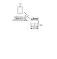
- Fig. 1 is a diagram illustrating the outline of a communication system.
- Fig. 2 is a diagram illustrating the hardware configuration of a printer.
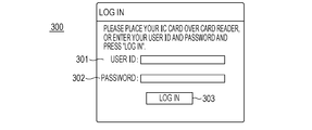
- Fig. 3A is a diagram illustrating a screen displayed by the printer.
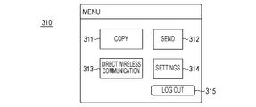
- Fig. 3B is a diagram illustrating a screen displayed by the printer.
- Fig. 3C is a diagram illustrating a screen displayed by the printer.
- Fig. 4 is a diagram illustrating a user management table.
- Fig. 5A is a diagram illustrating a wireless connection screen.
- Fig. 5B is a diagram illustrating a wireless connection screen.
- Fig. 6 is a flowchart illustrating a process regarding user authentication.
- Fig. 7 is a flowchart illustrating a process regarding operation in an access point mode.
- Fig. 8 is a flowchart illustrating a process regarding operation in the access point mode.
- the communication system includes a printer 100 and a mobile terminal 101.
- the printer 100 has a wireless LAN function.
- the wireless LAN function of the printer 100 has two wireless communication modes, that is, an infrastructure mode and an access point mode.
- the infrastructure mode is a wireless communication mode where the printer 100 connects wirelessly to a relay device such as an access point (not illustrated) and communicates with a device such as a personal computer (PC) on a network.
- a relay device such as an access point (not illustrated)
- PC personal computer
- the access point mode is a wireless communication mode where a software access point is activated on the printer 100 and the printer 100 itself acts as an access point.
- the mobile terminal 101 such as a smartphone wirelessly connects to the printer 100 operating in the access point mode and transmits print data for printing an electronic file such as a photograph to the printer 100.
- wireless communication can be performed directly between the printer 100 and the mobile terminal 101, without having a relay device such as an access point therebetween.
- the access point mode is an example of a direct wireless communication mode of establishing wireless connection directly between the printer 100 and the mobile terminal 101.
- other wireless communication systems such as Wi-Fi Direct (registered trademark) may be applied to the first embodiment.
- the printer 100 has a user authenticating function, which will be described in detail later.
- the user logs in to the printer 100 with the user authenticating function.
- the user who has logged in to the printer 100 can use the access point mode.
- the printer 100 stops operating in the access point in conjunction with the user's logging out.
- a central processing unit (CPU) 201 reads a control program stored in a read-only memory (ROM) 202 and executes various processes for controlling the operation of the printer 100.
- the ROM 202 stores the control program.
- a random-access memory (RAM) 203 is used as a temporary storage area such a main memory or a work area for the CPU 201.
- a hard disk drive (HDD) 204 is a non-volatile storage medium for storing various types of data.
- one CPU 201 executes processes illustrated in later-described flowcharts in the case of the printer 100, other modes are also conceivable. For example, a plurality of CPUs may cooperate to execute the processes illustrated in the later-described flowcharts. Alternatively, part or some of the processes illustrated in the later-described flowcharts may be executed using a hardware circuit such as an application-specific integrated circuit (ASIC).
- ASIC application-specific integrated circuit
- a wireless LAN interface (I/F) 205 executes wireless LAN communication between the mobile terminal 101 and an external device such as an access point.
- Wireless LAN communication executed by the wireless LAN I/F 205 is wireless communication such as Institute of Electrical and Electronics Engineers (IEEE) 802.11 a/b/g/n/ac.
- IEEE Institute of Electrical and Electronics Engineers
- the wireless LAN I/F 205 is operable in the infrastructure mode and the access point mode.
- the wireless LAN I/F 205 selects one of the infrastructure mode and the access point mode in accordance with device settings configured in advance by the user, and operates in the selected mode.
- a network I/F 210 connects to a wired LAN via a LAN cable.
- the network I/F 210 is capable of communicating with an external device (such as a PC) on the wired LAN.
- a printing section 206 executes printing on a sheet on the basis of print data received by the wireless LAN I/F 205 or the network I/F 210.
- a scanning section 207 scans a document placed by the user and generates a document image. The document image generated by the scanning section 207 is printed (so-called copied) by the printing section 206 or accumulated in the HDD 204.
- An operating section 208 includes a liquid crystal display (LCD) with a touchscreen function and a keyboard, and displays various operation screens. The user can input instructions and information to the printer 100 via the operating section 208.
- LCD liquid crystal display
- An integrated circuit (IC) card reader 209 reads user information from an IC card.
- a user ID and a password are stored as user information in an IC card.
- the printer 100 executes user authentication on the basis of user information read by the IC card reader 209 from an IC card.
- the printer 100 is given as an example of a communication apparatus operable in the access point mode.
- a communication apparatus to which the present invention is applicable is not limited to the printer 100.
- the present invention is applicable to various communication apparatuses including a digital camera, a camcorder, a smartphone, and a portable game machine as long as they are operable in the access point mode.
- a log-in screen 300 illustrated in Fig. 3A is a screen displayed by the operating section 208 of the printer 100.
- the operating section 208 initially displays the log-in screen 300.
- the user places his/her IC card over the IC card reader 209.
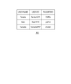
- a user management table 400 illustrated in Fig. 4 is information for managing user information (user name, user ID, and password) on a user who is permitted to log in to the printer 100, and is stored in the HDD 204 of the printer 100.
- a user who is registered in the user management table 400 can log in to the printer 100.
- the IC card reader 209 reads user information (user ID and password) from the IC card.
- the CPU 201 determines whether the user information, read by the IC card reader 209 from the IC card, is registered in the user management table 400.
- the operating section 208 displays a menu screen 310 illustrated in Fig. 3B.
- the state becomes such that the user who has been successfully authenticated logs in to the printer 100 and can use the printer 100.
- the user information read from the IC card is not registered in the user management table 400, the user authentication failed, and the operating section 208 informs the user of the authentication failure and does not display the menu screen 310.
- the user may enter his/her user ID and password in an entry field 301 and an entry field 302, without using the IC card reader 209.
- the printer 100 executes user authentication.
- the user management table 400 may be included not in the printer 100, but in an external authentication server.
- the printer 100 transmits the user information to the authentication server.
- the printer 100 executes user authentication.
- the menu screen 310 illustrated in Fig. 3B displays buttons for the user to use functions provided by the printer 100.
- a log-out button 315 is a button for the user to log out from the printer 100. When the user presses the log-out button 315, the user who is currently logged in logs out from the printer 100.
- a log-out button is displayed on screens described hereinafter, and the user can input a log-out instruction when the operating section 208 displays any of these screens.
- a button 311 is a button for the user to use a copy function.
- the operating section 208 displays a copy screen (not illustrated).
- a button 312 is a button for the user to use a send function (function of transmitting a document image generated by the scanning section 207 to an external device).
- a send function function of transmitting a document image generated by the scanning section 207 to an external device.
- the operating section 208 displays a send screen (not illustrated).
- a button 314 is a button for the user to configure device settings of the printer 100.
- the operating section 208 displays various setting screens in accordance with the user operation.
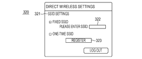
- a setting screen 320 illustrated in Fig. 3C is one of the operation screens provided by the printer 100 to the user, and is displayed by the operating section 208. Items that can be set on the setting screen 320 will be described in detail.
- the setting screen 320 is a screen accessible to a user who has special privileges, such as a system administrator.
- An item 321 is for setting which of a fixed service set identifier (SSID) and a one-time SSID is to be used as an SSID used in the access point mode.
- a fixed SSID is a setting that indicates that the same SSID is used whenever the printer 100 operates in the access point mode.
- the system administrator enters a desired SSID in an entry field 322.
- the printer 100 uses the SSID entered in the entry field 322 as a fixed SSID.
- a one-time SSID is a setting that indicates that a random SSID is generated and that random SSID is used.
- a register button 323 is a button for reflecting the settings configured on the setting screen 320 in the printer 100.
- the system administrator presses the register button 323 the results of the settings configured on the setting screen 320 are stored in the HDD 204, and the settings configured on the setting screen 320 are reflected in the printer 100.
- a button 313 is a button for the user to use the access point mode.
- the user first presses the button 313.
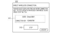
- the operating section 208 displays a wireless connection screen 500 illustrated in Fig. 5A.
- the wireless connection screen 500 displays a start button 501.
- the start button 501 is a button for the user to instruct the printer 100 to start operating in the access point mode.
- the operating section 208 is displaying the wireless connection screen 500, the printer 100 has not started operating in the access point mode. Thus, even when the mobile terminal 101 searches for surrounding access points, the mobile terminal 101 cannot find the printer 100, and no wireless connection can be established between the mobile terminal 101 and the printer 100.
- the user needs to instruct the printer 100 to start operating in the access point mode.
- the printer 100 starts operating in the access point mode.
- the operating section 208 displays a wireless connection screen 510 illustrated in Fig. 5B.
- the printer 100 When the printer 100 starts operating in the access point mode, the printer 100 generates an SSID and a connection key (such as a Wired Equivalent Privacy (WEP) key).
- a field 511 of the wireless connection screen 510 displays the SSID and connection key generated by the printer 100.
- a fixed SSID is generated and displayed in the field 511.
- a random SSID is generated and displayed in the field 511.
- the user who has checked the details displayed in the field 511 uses his/her mobile terminal 101 to search for surrounding access points, and selects an access point with the SSID displayed in the field 511 from the search result list.
- wireless connection based on the access point mode is established between the printer 100 and the mobile terminal 101.
- the user selects on the mobile terminal 101 a photograph that the user wants to print.
- the mobile terminal 101 uses wireless communication in the access point mode to transmit print data for printing the photograph selected by the user to the printer 100.
- the printer 100 executes printing based on the received print data on a sheet.
- the printer 100 When the printer 100 starts operating in the access point mode, the printer 100 enters a standby state for receiving a request for establishing wireless connection from an external device such as the mobile terminal 101. When the printer 100 starts operating in the access point mode, the mobile terminal 101 can find the printer 100 when searching for surrounding access points. On receipt of a request from an external device for establishing wireless communication, the printer 100 establishes wireless connection in the access point mode with the external device. After establishing the wireless connection, actual data communication (such as transmission of print data from the mobile terminal 101 to the printer 100) is executed between the printer 100 and the external device.
- the wireless connection screen 510 displays a stop button 512.
- the stop button 512 is for receiving from the user a stop instruction for stopping the operation in the access point mode.
- the printer 100 stops operating in the access point mode.
- the printer 100 also stops operating in the access point mode when the user logs out from the printer 100.
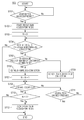
- a process executed by the printer 100 when the user logs in to the printer 100 will be described using a flowchart illustrated in Fig. 6.
- Each step illustrated in the flowchart in Fig. 6 is processed when the CPU 201 expands and executes a control program stored in a memory such as the ROM 202 or the like in the RAM 203.
- the printer 100 may be configured such that at least some of the steps of the flowchart illustrated in Fig. 6 are executed by the CPU 201, and the remaining steps are executed by a CPU (not illustrated) different from the CPU 201.
- step S601 the CPU 201 determines whether to execute user authentication.
- the CPU 201 determines whether to execute user authentication.
- the CPU 201 determines to execute user authentication. The process proceeds to step S602.
- step S602 the CPU 201 determines whether a user indicated by the user information is a user who is permitted to log in. This determination is done by checking whether the user information is registered in the user management table 400. When the user information is registered in the user management table 400 (the user authentication is successful), the process proceeds to step S603. In step S603, the CPU 201 executes log-in processing. The CPU 201 lets the user who has been successfully authenticated log in to the printer 100, and controls the operating section 208 to display the menu screen 310.
- step S602 when the user information is not registered in the user management table 400 (the user authentication failed), it is determined in step S602 that the user indicated by the user information is a user who is not permitted to log in.
- the CPU 201 informs the user of the authentication failure, and ends the process, without executing log-in processing.
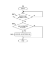
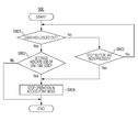
- a process executed by the printer 100 when the user uses the access point mode and the printer 100 automatically stops operating in conjunction with the user's logging out will be described using a flowchart illustrated in Fig. 7.
- Each step illustrated in the flowchart in Fig. 7 is processed when the CPU 201 expands and executes a control program stored in a memory such as the ROM 202 or the like in the RAM 203.
- the printer 100 may be configured such that at least some of the steps of the flowchart illustrated in Fig. 7 are executed by the CPU 201, and the remaining steps are executed by a CPU (not illustrated) different from the CPU 201.
- step S701 the CPU 201 determines whether the user has pressed the start button 501. When the CPU 201 detects that the user has pressed the start button 501, the process proceeds to step S702. In step S702, the CPU 201 controls the wireless LAN I/F 205 to start the operation in the access point mode.
- the wireless LAN I/F 205 generates a fixed SSID or a one-time SSID in accordance with the results of the settings configured on the setting screen 320, and starts the operation in the access point mode.
- the CPU 201 sets zero as the value of a variable N.
- the variable N is a variable for managing the number of devices with which wireless connection in the access mode has been established by the printer 100.
- the printer 100 can simultaneously establish wireless connection in the access point mode with up to five devices.
- the value five is only one example of the maximum value of the number of concurrent connections, and the value may be another value.
- the first embodiment describes that the maximum value of the number of concurrent connections remains unchanged even when either of a fixed SSID and a one-time SSID is used, the maximum value of the number of concurrent connections may be made different between the case of using a fixed SSID and the case of using a one-time SSID.
- step S704 the CPU 201 determines whether a request from an external device for establishing wireless connection has been received.
- the wireless LAN I/F 205 receives a request from an external device for establishing wireless connection, the process proceeds to step S705.
- the wireless LAN I/F 205 does not receive a request from an external device for establishing wireless connection, the process proceeds to step S709.
- step S705 the CPU 201 determines whether the value of the variable N is less than the maximum value of the number of concurrent connections.
- the CPU 201 controls the wireless LAN I/F 205 to establish wireless connection with the device, which has sent the request for establishing wireless connection.
- the wireless LAN I/F 205 establishes wireless connection in the access point mode with the device, which has sent the request for establishing wireless connection.
- the CPU 201 increments the value of the variable N by one.
- step S708 the CPU 201 rejects the request for establishing wireless connection.
- the device, which has sent the request for establishing wireless connection fails to establish wireless connection in the access point mode with the printer 100.
- step S709 the CPU 201 determines whether the user who is currently logged in to the printer 100 has logged out from the printer 100.
- the user logs out when the user presses the log-out button or when a certain period of time (such as five minutes) elapses without any user operation.
- the process proceeds to step S710.
- the process proceeds to step S711.
- step S710 the CPU 201 determines whether the value of the variable N is less than or equal to one.
- the value of the variable N that is, the number of devices with which wireless connection in the access point mode has been established at present, is less than or equal to one.
- the process proceeds to step S712.
- step S712 the CPU 201 controls the wireless LAN I/F 205 to stop the operation in the access point mode. Under control of the CPU 201, the wireless LAN I/F 205 stops the operation in the access point mode.
- the CPU 201 ends the process illustrated in the flowchart, without having the wireless LAN I/F 205 stop the operation in the access point mode.
- the printer 100 is characterized in that the printer 100 determines whether to stop operating in the access point mode in conjunction with the user's logging out, on the basis of the number of wireless connections established in the access point mode.
- step S710 When the value of the variable N, that is, the number of devices with which wireless connection in the access point mode has been established at present, is zero, it is determined “Yes" in step S710, and the wireless LAN I/F 205 stops the operation in the access point mode.
- the fact that the value of the variable N is zero can be determined that there is no user who uses the access point mode.
- the wireless LAN I/F 205 stops the operation in the access point mode in conjunction with the user's logging out.
- step S710 When the value of the variable N, that is, the number of devices with which wireless connection in the access point mode has been established at present, is one, it is determined “Yes" in step S710, and the wireless LAN I/F 205 stops the operation in the access point mode.
- the fact that the value of the variable N is one can be determined that it is highly likely that only the user who is currently logged uses the access point mode, and no other users use the access point mode. Thus, when the value of the variable N is one, the wireless LAN I/F 205 stops the operation in the access point mode in conjunction with the user's logging out.
- the wireless LAN I/F 205 does not stop the operation in the access point mode.
- the value of the variable N is plural, it can be determined that it is highly likely that, besides the user who is currently logged in, other users also use the access point mode. If the operation in the access point mode is stopped in this state in conjunction with the user's logging out, it becomes impossible for the other users to use the access point mode.
- the wireless LAN I/F 205 does not stop the operation in the access point mode even when the user logs out.
- step S711 the CPU 201 determines whether the user has pressed the stop button 512.
- the CPU 201 detects that the user has pressed the stop button 512, the process proceeds to step S712.
- step S712 the CPU 201 controls the wireless LAN I/F 205 to stop the operation in the access point mode, and the wireless LAN I/F 205 stops the operation in the access point mode.
- the CPU 201 determines in step S711 that the user has not pressed the stop button 512, the process proceeds to step S704.
- the printer 100 can stop operating in the access point in conjunction with the user's logging out from the printer 100.
- the wireless LAN I/F 205 operates in one of the infrastructure mode and the access point mode, and is incapable of simultaneously operating in both the infrastructure mode and the access point mode.
- the wireless LAN I/F 205 can neither operate in the infrastructure mode nor receive print data from a PC via an external access point mode. Therefore, in the first embodiment, the wireless LAN I/F 205 automatically stops the operation in the access point mode in conjunction with the user's logging out. By automatically stopping the operation in the access point mode in conjunction with the user's logging out, the operation mode of the wireless LAN I/F 205 can be switched from the access point mode to the infrastructure mode.
- a second embodiment will be described.
- a process of switching, on the basis of the type of SSID used in the access point mode, whether to stop the operation in the access point mode in conjunction with the user's logging out will be described.
- the configuration of the printer 100 is the same as that in the first embodiment.
- the printer 100 sets one of a fixed SSID and a one-time SSID as an SSID used in the access point mode.
- the maximum value of the number of concurrent connections in the case of using a fixed SSID is plural (such as five), and the maximum value of the number of concurrent connections in the case of using a one-time SSID is one.
- the wireless LAN I/F 205 stops the operation in the access point mode in conjunction with the user's logging out.
- the wireless LAN I/F 205 does not stop the operation in the access point mode even when the user logs out.
- FIG. 8 This process will be described using a flowchart illustrated in Fig. 8.
- Each step illustrated in the flowchart in Fig. 8 is processed when the CPU 201 expands and executes a control program stored in a memory such as the ROM 202 or the like in the RAM 203.
- the printer 100 may be configured such that at least some of the steps of the flowchart illustrated in Fig. 8 are executed by the CPU 201, and the remaining steps are executed by a CPU (not illustrated) different from the CPU 201.
- step S801 the CPU 201 determines whether the user who is currently logged in to the printer 100 has logged out from the printer 100.
- the user logs out when the user presses the log-out button or when a certain period of time (such as five minutes) elapses without any user operation.
- the process proceeds to step S802.
- step S803 the CPU 201 determines whether the user has pressed the stop button 512.
- the process proceeds to step S804.
- Step S802 will be described.
- the CPU 201 determines whether the settings regarding the access point mode, which are configured on the printer 100, indicate the use of a one-time SSID. This determination is executed by checking the results of the settings configured on the setting screen 320.
- the process proceeds to step S804.
- the CPU 201 controls the wireless LAN I/F 205 to stop the operation in the access point mode. Under control of the CPU 201, the wireless LAN I/F 205 stops the operation in the access point mode.
- the CPU 201 ends the process illustrated in the flowchart, without having the wireless LAN I/F 205 stop the operation in the access point mode.
- step S802 When the settings regarding the access point mode indicate the use of a one-time SSID, it is determined "Yes" in step S802, and the wireless LAN I/F 205 stops the operation in the access point mode.
- the maximum value of the number of concurrent wireless connections in the access point mode is one. The fact that the maximum value of the number of concurrent connections is one can be determined that the use of the access point mode ends when the user logs out, since it is assumed that the access point mode is used only by the user who is currently logged in.
- the wireless LAN I/F 205 stops the operation in the access point mode in conjunction with the user's logging out.
- the wireless LAN I/F 205 does not stop the operation in the access point mode.
- the maximum value of the number of concurrent wireless connections in the access point mode is plural (such as five). The fact that the maximum value of the number of concurrent connections is plural can be determined that it is preferable that the printer 100 not stop operating in the access point mode since it is assumed that the access point mode is used by a plurality of users with their desired timings.
- the wireless LAN I/F 205 does not stop the operation in the access point mode and continues the operation in the access point mode even when the user logs out from the printer 100.
- the printer 100 is characterized in that the printer 100 determines whether to stop operating in the access point mode in conjunction with the user's logging out, on the basis of the type of SSID used in the access point mode.
- the printer 100 determines whether to stop operating in the access point mode in conjunction with the user's logging out, on the basis of the type of SSID used in the access point mode.
- an SSID used in the access point mode is a one-time SSID
- the printer 100 stops operating in the access point mode in conjunction with the user's logging out.
- an SSID used in the access point mode is a fixed SSID
- the printer 100 does not stop operating in the access point mode even when the user logs out.
- the second embodiment has given a one-time SSID as an example of an SSID where the maximum value of the number of concurrent connections is one
- the present application is applicable to, instead of a one-time SSID, any other type of SSID as long as the maximum value of the number of concurrent connections is one.
- SSID for example, the setting indicating that an SSID corresponding to a user is generated and that SSID is used in the access point mode is conceivable.
- the printer 100 switches the to-be-used SSID in accordance with a user who is currently logged in.
- the printer 100 uses a user SSID for the user A; and, when a user B is currently logged in, the printer 100 uses a user SSID for the user B. It is preferable that the maximum value of the number of concurrent connections be one even in such a case where an SSID corresponding to a user is used in the access point mode, and it is also preferable that the printer 100 stop operating in the access point mode in conjunction with the user's logging out.
- Embodiment(s) of the present invention can also be realized by a computer of a system or apparatus that reads out and executes computer executable instructions (e.g., one or more programs) recorded on a storage medium (which may also be referred to more fully as a 'non-transitory computer-readable storage medium') to perform the functions of one or more of the above-described embodiment(s) and/or that includes one or more circuits (e.g., application specific integrated circuit (ASIC)) for performing the functions of one or more of the above-described embodiment(s), and by a method performed by the computer of the system or apparatus by, for example, reading out and executing the computer executable instructions from the storage medium to perform the functions of one or more of the above-described embodiment(s) and/or controlling the one or more circuits to perform the functions of one or more of the above-described embodiment(s).
- computer executable instructions e.g., one or more programs
- a storage medium which may also be referred to more fully as
- the computer may comprise one or more processors (e.g., central processing unit (CPU), micro processing unit (MPU)) and may include a network of separate computers or separate processors to read out and execute the computer executable instructions.
- the computer executable instructions may be provided to the computer, for example, from a network or the storage medium.
- the storage medium may include, for example, one or more of a hard disk, a random-access memory (RAM), a read only memory (ROM), a storage of distributed computing systems, an optical disk (such as a compact disc (CD), digital versatile disc (DVD), or Blu-ray Disc (BD) TM ), a flash memory device, a memory card, and the like.
Abstract
Description
Claims (13)
- A communication apparatus to which a user can log in, comprising:
a wireless communication unit configured to include a direct wireless communication function of performing wireless communication with an external device without having a relay device therebetween;
a determination unit configured to determine, in accordance with a number of wireless connections established by the direct wireless communication function, whether to stop the direct wireless communication function in response to the user's logging out from the communication apparatus; and
a controller configured to control the wireless communication unit to stop the direct wireless communication function in response to determining by the determination unit to stop the direct wireless communication function. - The communication apparatus according to Claim 1, wherein the determination unit determines to stop the direct wireless communication function when the number of wireless connections is zero.
- The communication apparatus according to Claim 1, wherein the determination unit determines to stop the direct wireless communication function when the number of wireless connections is zero or one.
- The communication apparatus according to Claim 1, wherein the communication apparatus is a printer.
- The communication apparatus according to Claim 1, wherein the direct wireless communication function is an access point mode where the communication apparatus acts as an access point.
- A communication apparatus to which a user can log in, comprising:
a wireless communication unit configured to include a direct wireless communication function of performing wireless communication with an external device without having a relay device therebetween; and
a controller configured to control the wireless communication unit to stop the direct wireless communication function in response to the user's logging out from the communication apparatus when a certain setting is configured on the communication apparatus, the certain setting indicating a service set identifier (SSID) used in the direct wireless communication function. - The communication apparatus according to Claim 6, wherein, when the certain setting is not configured on the communication apparatus, the wireless communication unit does not stop the direct wireless communication function at a time point at which the user logs out from the communication apparatus.
- The communication apparatus according to Claim 6, wherein the certain setting is a setting indicating that an SSID where a maximum value of a number of concurrent wireless connections is one is used.
- The communication apparatus according to Claim 6, wherein the certain setting is a setting indicating that a randomly-generated SSID is used.
- The communication apparatus according to Claim 6, wherein the communication apparatus is a printer.
- The communication apparatus according to Claim 6, wherein the direct wireless communication function is an access point mode where the communication apparatus acts as an access point.
- A method for controlling a communication apparatus to which a user can log in, the communication apparatus including a direct wireless communication function of performing wireless communication with an external device without having a relay device therebetween, comprising:
determining, in accordance with a number of wireless connections established by the direct wireless communication function, whether to stop the direct wireless communication function in response to the user's logging out from the communication apparatus; and
controlling the communication apparatus to stop the direct wireless communication function in response to determining to stop the direct wireless communication function. - A method for controlling a communication apparatus to which a user can log in, the communication apparatus including a direct wireless communication function of performing wireless communication with an external device without having a relay device therebetween, comprising:
controlling the communication apparatus to stop the direct wireless communication function in response to the user's logging out from the communication apparatus when a certain setting is configured on the communication apparatus, the certain setting indicating an SSID used in the direct wireless communication function.
Priority Applications (4)
| Application Number | Priority Date | Filing Date | Title |
|---|---|---|---|
| EP16868202.9A EP3381238B1 (en) | 2015-11-28 | 2016-11-25 | Communication apparatus and method for controlling the same |
| KR1020187018226A KR102128774B1 (en) | 2015-11-28 | 2016-11-25 | Communication device and communication device control method |
| CN201680069101.1A CN108293274B (en) | 2015-11-28 | 2016-11-25 | Communication apparatus and control method of communication apparatus |
| US15/778,069 US10798758B2 (en) | 2015-11-28 | 2016-11-25 | Communication apparatus and method for controlling the same |
Applications Claiming Priority (2)
| Application Number | Priority Date | Filing Date | Title |
|---|---|---|---|
| JP2015-232516 | 2015-11-28 | ||
| JP2015232516A JP6611572B2 (en) | 2015-11-28 | 2015-11-28 | COMMUNICATION DEVICE, COMMUNICATION DEVICE CONTROL METHOD, AND PROGRAM |
Publications (1)
| Publication Number | Publication Date |
|---|---|
| WO2017090251A1 true WO2017090251A1 (en) | 2017-06-01 |
Family
ID=58764264
Family Applications (1)
| Application Number | Title | Priority Date | Filing Date |
|---|---|---|---|
| PCT/JP2016/004955 WO2017090251A1 (en) | 2015-11-28 | 2016-11-25 | Communication apparatus and method for controlling the same |
Country Status (6)
| Country | Link |
|---|---|
| US (1) | US10798758B2 (en) |
| EP (1) | EP3381238B1 (en) |
| JP (1) | JP6611572B2 (en) |
| KR (1) | KR102128774B1 (en) |
| CN (2) | CN113543133A (en) |
| WO (1) | WO2017090251A1 (en) |
Families Citing this family (8)
| Publication number | Priority date | Publication date | Assignee | Title |
|---|---|---|---|---|
| JP6655924B2 (en) * | 2015-09-17 | 2020-03-04 | キヤノン株式会社 | Communication device, communication device control method, and program |
| JP6766677B2 (en) * | 2017-02-17 | 2020-10-14 | ブラザー工業株式会社 | Computer program for terminal equipment |
| JP6853742B2 (en) * | 2017-06-27 | 2021-03-31 | キヤノン株式会社 | Image processing device, its control method, and program |
| JP6868533B2 (en) * | 2017-10-17 | 2021-05-12 | 株式会社沖データ | Image forming system and image forming device |
| JP7191189B2 (en) | 2018-01-26 | 2022-12-16 | キヤノン株式会社 | Information processing device, its control method, and program |
| JP6993890B2 (en) * | 2018-01-26 | 2022-01-14 | キヤノン株式会社 | Information processing equipment, its control method, and programs |
| JP7145752B2 (en) * | 2018-12-27 | 2022-10-03 | セイコーインスツル株式会社 | PRINTING SYSTEM, HOST DEVICE, PRINT CONTROL METHOD, AND PROGRAM |
| JP7296051B2 (en) * | 2019-06-28 | 2023-06-22 | ブラザー工業株式会社 | Printer and communication processing system |
Citations (2)
| Publication number | Priority date | Publication date | Assignee | Title |
|---|---|---|---|---|
| US20140268222A1 (en) | 2013-03-15 | 2014-09-18 | Canon Kabushiki Kaisha | Communication apparatus, control method thereof, printing apparatus, and storage medium |
| JP2015023440A (en) | 2013-07-19 | 2015-02-02 | キヤノン株式会社 | Communication device, communication method, and program |
Family Cites Families (37)
| Publication number | Priority date | Publication date | Assignee | Title |
|---|---|---|---|---|
| CN100415534C (en) * | 2003-08-08 | 2008-09-03 | 佳能株式会社 | Recording apparatus, image supply device, and recording system, and control method and program thereof |
| JP4560366B2 (en) * | 2004-09-30 | 2010-10-13 | キヤノン株式会社 | Wireless communication device |
| JP4656637B2 (en) * | 2005-04-27 | 2011-03-23 | キヤノン株式会社 | COMMUNICATION DEVICE, COMMUNICATION SYSTEM AND COMMUNICATION PARAMETER SETTING METHOD |
| KR101085905B1 (en) * | 2007-03-13 | 2011-11-23 | 삼성전자주식회사 | Wireless network printing system |
| KR101554743B1 (en) * | 2009-06-18 | 2015-09-22 | 삼성전자주식회사 | Method for automatic connectting of wireless lan between devices and the device therefor |
| US8965283B2 (en) * | 2009-08-10 | 2015-02-24 | Qualcomm Incorporated | Setting up a direct link in a peer to peer wireless network |
| US8965386B2 (en) * | 2009-09-02 | 2015-02-24 | Broadcom Corporation | Providing femtocell access via personal communication devices |
| JP5440123B2 (en) * | 2009-11-24 | 2014-03-12 | ソニー株式会社 | Wireless communication apparatus, wireless communication system, wireless communication method, and program |
| WO2011132818A1 (en) * | 2010-04-23 | 2011-10-27 | 엘지전자 주식회사 | Method and apparatus for direct communications in a wireless communication system |
| US9521277B1 (en) * | 2010-05-20 | 2016-12-13 | Marvell International Ltd. | Method to associate mobile device with printer |
| KR101739040B1 (en) * | 2010-11-23 | 2017-05-23 | 에스케이텔레콤 주식회사 | Low-Power Mode Operation of Compound Terminal and Device Using The Same |
| JP2012155575A (en) * | 2011-01-27 | 2012-08-16 | Seiko Epson Corp | Print control server and print system |
| US8554970B2 (en) * | 2011-04-18 | 2013-10-08 | Nokia Corporation | Method, apparatus and computer program product for creating a wireless docking group |
| KR102006405B1 (en) * | 2011-12-12 | 2019-08-01 | 휴렛-팩커드 디벨롭먼트 컴퍼니, 엘.피. | Image forming apparatus supporting Peer-to-Peer connection and method of performing image forimg operation thereof |
| JP5887969B2 (en) * | 2012-02-07 | 2016-03-16 | セイコーエプソン株式会社 | Wireless communication equipment |
| JP5966527B2 (en) * | 2012-03-30 | 2016-08-10 | ブラザー工業株式会社 | Communication device |
| US8847281B2 (en) | 2012-07-27 | 2014-09-30 | Intel Corporation | High mobility strained channels for fin-based transistors |
| JP5994619B2 (en) * | 2012-12-17 | 2016-09-21 | ブラザー工業株式会社 | Communication device, communication system |
| JP6242051B2 (en) * | 2013-01-23 | 2017-12-06 | キヤノン株式会社 | COMMUNICATION DEVICE, COMMUNICATION DEVICE CONTROL METHOD, PROGRAM |
| JP6112903B2 (en) * | 2013-02-22 | 2017-04-12 | キヤノン株式会社 | COMMUNICATION DEVICE, COMMUNICATION DEVICE CONTROL METHOD, COMPUTER PROGRAM |
| JP5907094B2 (en) * | 2013-02-28 | 2016-04-20 | ブラザー工業株式会社 | Terminal device and function execution device |
| JP6222950B2 (en) * | 2013-03-15 | 2017-11-01 | キヤノン株式会社 | Printing apparatus, control method thereof, and program |
| JP6118187B2 (en) * | 2013-06-12 | 2017-04-19 | キヤノン株式会社 | Printing apparatus, printing apparatus control method, and program |
| US20150163841A1 (en) * | 2013-12-11 | 2015-06-11 | Lenovo (Beijing) Co., Ltd. | Method for processing information and electronic apparatus |
| JP6444067B2 (en) * | 2014-06-05 | 2018-12-26 | キヤノン株式会社 | COMMUNICATION DEVICE, ITS CONTROL METHOD, AND PROGRAM |
| JP2016015682A (en) * | 2014-07-03 | 2016-01-28 | セイコーエプソン株式会社 | Communication system, communication setting method, and terminal device |
| JP6350073B2 (en) * | 2014-07-29 | 2018-07-04 | セイコーエプソン株式会社 | Device control apparatus, device control method, and device control program |
| WO2016017908A1 (en) * | 2014-07-31 | 2016-02-04 | 엘지전자(주) | Method and apparatus for controlling electronic device in wireless communication system supporting bluetooth communication |
| WO2016017907A1 (en) * | 2014-07-31 | 2016-02-04 | 엘지전자(주) | Method and apparatus for controlling electronic device in wireless communication system supporting bluetooth communication |
| WO2016024399A1 (en) * | 2014-08-12 | 2016-02-18 | 日本電気株式会社 | Method and system for communicating between groups in wireless communication network |
| JP6459309B2 (en) * | 2014-08-29 | 2019-01-30 | セイコーエプソン株式会社 | Printing device |
| KR20160053594A (en) * | 2014-11-05 | 2016-05-13 | 삼성전자주식회사 | Method for connecting to device and apparatus supporting wi-fi direct for performing the same |
| US20170346891A1 (en) * | 2014-12-15 | 2017-11-30 | Nec Corporation | Communication method |
| US20170359696A1 (en) * | 2014-12-26 | 2017-12-14 | Nec Corporation | Communication method |
| JP6582445B2 (en) * | 2015-03-05 | 2019-10-02 | 日本電気株式会社 | Thin client system, connection management device, virtual machine operating device, method, and program |
| JP6481462B2 (en) * | 2015-03-27 | 2019-03-13 | 富士ゼロックス株式会社 | Image forming apparatus search method, portable terminal, and program |
| US10244379B2 (en) * | 2015-05-20 | 2019-03-26 | Nec Corporation | Scheduled group reformation among multiple P2P groups following switching schedule |
-
2015
- 2015-11-28 JP JP2015232516A patent/JP6611572B2/en active Active
-
2016
- 2016-11-25 CN CN202110804169.2A patent/CN113543133A/en active Pending
- 2016-11-25 EP EP16868202.9A patent/EP3381238B1/en active Active
- 2016-11-25 KR KR1020187018226A patent/KR102128774B1/en active IP Right Grant
- 2016-11-25 US US15/778,069 patent/US10798758B2/en active Active
- 2016-11-25 CN CN201680069101.1A patent/CN108293274B/en active Active
- 2016-11-25 WO PCT/JP2016/004955 patent/WO2017090251A1/en active Application Filing
Patent Citations (2)
| Publication number | Priority date | Publication date | Assignee | Title |
|---|---|---|---|---|
| US20140268222A1 (en) | 2013-03-15 | 2014-09-18 | Canon Kabushiki Kaisha | Communication apparatus, control method thereof, printing apparatus, and storage medium |
| JP2015023440A (en) | 2013-07-19 | 2015-02-02 | キヤノン株式会社 | Communication device, communication method, and program |
Also Published As
| Publication number | Publication date |
|---|---|
| CN108293274B (en) | 2021-07-20 |
| CN113543133A (en) | 2021-10-22 |
| CN108293274A (en) | 2018-07-17 |
| US20180352591A1 (en) | 2018-12-06 |
| KR102128774B1 (en) | 2020-07-08 |
| EP3381238A4 (en) | 2019-07-31 |
| US10798758B2 (en) | 2020-10-06 |
| EP3381238A1 (en) | 2018-10-03 |
| KR20180088433A (en) | 2018-08-03 |
| EP3381238B1 (en) | 2021-03-17 |
| JP2017098917A (en) | 2017-06-01 |
| JP6611572B2 (en) | 2019-11-27 |
Similar Documents
| Publication | Publication Date | Title |
|---|---|---|
| EP3381238B1 (en) | Communication apparatus and method for controlling the same | |
| KR102093639B1 (en) | Communication apparatus having direct wireless communication function and method for controlling communication apparatus | |
| US11950095B2 (en) | Communication apparatus and method for controlling the same | |
| EP2916517A1 (en) | Information processing apparatus, control method, program, and storage medium storing program | |
| US10642548B2 (en) | Printing apparatus and control method of printing apparatus | |
| US10761792B2 (en) | Printing apparatus, control method of printing apparatus and storage medium, relating to determining an owner of print data | |
| JP7187588B2 (en) | IMAGE PROCESSING DEVICE, CONTROL METHOD AND PROGRAM OF IMAGE PROCESSING DEVICE | |
| JP7305815B2 (en) | IMAGE PROCESSING DEVICE, CONTROL METHOD AND PROGRAM OF IMAGE PROCESSING DEVICE | |
| JP6984051B2 (en) | Image processing device, control method and program of image processing device | |
| JP6884840B2 (en) | Communication equipment, control methods and programs for communication equipment |
Legal Events
| Date | Code | Title | Description |
|---|---|---|---|
| 121 | Ep: the epo has been informed by wipo that ep was designated in this application |
Ref document number: 16868202 Country of ref document: EP Kind code of ref document: A1 |
|
| NENP | Non-entry into the national phase |
Ref country code: DE |
|
| ENP | Entry into the national phase |
Ref document number: 20187018226 Country of ref document: KR Kind code of ref document: A |
|
| WWE | Wipo information: entry into national phase |
Ref document number: 2016868202 Country of ref document: EP |
|
| ENP | Entry into the national phase |
Ref document number: 2016868202 Country of ref document: EP Effective date: 20180628 |