WO2017082344A1 - Ue、mme、ueの通信制御方法及びmmeの通信制御方法 - Google Patents
Ue、mme、ueの通信制御方法及びmmeの通信制御方法 Download PDFInfo
- Publication number
- WO2017082344A1 WO2017082344A1 PCT/JP2016/083365 JP2016083365W WO2017082344A1 WO 2017082344 A1 WO2017082344 A1 WO 2017082344A1 JP 2016083365 W JP2016083365 W JP 2016083365W WO 2017082344 A1 WO2017082344 A1 WO 2017082344A1
- Authority
- WO
- WIPO (PCT)
- Prior art keywords
- message
- attach
- mode
- procedure
- mme
- Prior art date
Links
- 238000000034 method Methods 0.000 title claims abstract description 363
- 238000004891 communication Methods 0.000 title claims abstract description 59
- 230000004044 response Effects 0.000 claims abstract description 34
- 230000005540 biological transmission Effects 0.000 claims description 254
- 230000008569 process Effects 0.000 claims description 53
- 238000003860 storage Methods 0.000 description 60
- 230000007704 transition Effects 0.000 description 60
- 230000006870 function Effects 0.000 description 39
- 230000004913 activation Effects 0.000 description 26
- 238000012217 deletion Methods 0.000 description 22
- 230000037430 deletion Effects 0.000 description 22
- 238000007726 management method Methods 0.000 description 18
- 230000008859 change Effects 0.000 description 12
- 238000012545 processing Methods 0.000 description 12
- 230000009471 action Effects 0.000 description 11
- 210000004027 cell Anatomy 0.000 description 11
- 238000010295 mobile communication Methods 0.000 description 11
- 239000004065 semiconductor Substances 0.000 description 8
- 230000011664 signaling Effects 0.000 description 8
- 238000012546 transfer Methods 0.000 description 7
- 238000005516 engineering process Methods 0.000 description 6
- 230000001413 cellular effect Effects 0.000 description 5
- 238000001514 detection method Methods 0.000 description 5
- 102000018059 CS domains Human genes 0.000 description 4
- 108050007176 CS domains Proteins 0.000 description 4
- 230000002159 abnormal effect Effects 0.000 description 3
- 230000000737 periodic effect Effects 0.000 description 3
- 238000013468 resource allocation Methods 0.000 description 3
- ATJFFYVFTNAWJD-UHFFFAOYSA-N Tin Chemical compound [Sn] ATJFFYVFTNAWJD-UHFFFAOYSA-N 0.000 description 2
- 230000002457 bidirectional effect Effects 0.000 description 2
- 238000000605 extraction Methods 0.000 description 2
- 210000004754 hybrid cell Anatomy 0.000 description 2
- 238000011084 recovery Methods 0.000 description 2
- CSRZQMIRAZTJOY-UHFFFAOYSA-N trimethylsilyl iodide Substances C[Si](C)(C)I CSRZQMIRAZTJOY-UHFFFAOYSA-N 0.000 description 2
- 238000013475 authorization Methods 0.000 description 1
- 230000008901 benefit Effects 0.000 description 1
- VYLDEYYOISNGST-UHFFFAOYSA-N bissulfosuccinimidyl suberate Chemical compound O=C1C(S(=O)(=O)O)CC(=O)N1OC(=O)CCCCCCC(=O)ON1C(=O)C(S(O)(=O)=O)CC1=O VYLDEYYOISNGST-UHFFFAOYSA-N 0.000 description 1
- 238000005520 cutting process Methods 0.000 description 1
- 238000009795 derivation Methods 0.000 description 1
- 238000013461 design Methods 0.000 description 1
- 230000006866 deterioration Effects 0.000 description 1
- 238000010586 diagram Methods 0.000 description 1
- 230000000694 effects Effects 0.000 description 1
- 238000005538 encapsulation Methods 0.000 description 1
- 239000000284 extract Substances 0.000 description 1
- 230000010354 integration Effects 0.000 description 1
- 230000007774 longterm Effects 0.000 description 1
- 230000014759 maintenance of location Effects 0.000 description 1
- 238000004519 manufacturing process Methods 0.000 description 1
- 230000004048 modification Effects 0.000 description 1
- 238000012986 modification Methods 0.000 description 1
- 230000003287 optical effect Effects 0.000 description 1
- 238000005457 optimization Methods 0.000 description 1
- 230000000717 retained effect Effects 0.000 description 1
- 101150079036 rnc gene Proteins 0.000 description 1
- 238000010187 selection method Methods 0.000 description 1
- 238000012384 transportation and delivery Methods 0.000 description 1
- 238000004846 x-ray emission Methods 0.000 description 1
Images


Classifications
-
- H—ELECTRICITY
- H04—ELECTRIC COMMUNICATION TECHNIQUE
- H04W—WIRELESS COMMUNICATION NETWORKS
- H04W4/00—Services specially adapted for wireless communication networks; Facilities therefor
- H04W4/20—Services signaling; Auxiliary data signalling, i.e. transmitting data via a non-traffic channel
-
- H—ELECTRICITY
- H04—ELECTRIC COMMUNICATION TECHNIQUE
- H04W—WIRELESS COMMUNICATION NETWORKS
- H04W76/00—Connection management
- H04W76/10—Connection setup
-
- H—ELECTRICITY
- H04—ELECTRIC COMMUNICATION TECHNIQUE
- H04W—WIRELESS COMMUNICATION NETWORKS
- H04W4/00—Services specially adapted for wireless communication networks; Facilities therefor
- H04W4/70—Services for machine-to-machine communication [M2M] or machine type communication [MTC]
-
- H—ELECTRICITY
- H04—ELECTRIC COMMUNICATION TECHNIQUE
- H04W—WIRELESS COMMUNICATION NETWORKS
- H04W72/00—Local resource management
- H04W72/20—Control channels or signalling for resource management
-
- H—ELECTRICITY
- H04—ELECTRIC COMMUNICATION TECHNIQUE
- H04W—WIRELESS COMMUNICATION NETWORKS
- H04W76/00—Connection management
- H04W76/10—Connection setup
- H04W76/12—Setup of transport tunnels
-
- H—ELECTRICITY
- H04—ELECTRIC COMMUNICATION TECHNIQUE
- H04W—WIRELESS COMMUNICATION NETWORKS
- H04W76/00—Connection management
- H04W76/10—Connection setup
- H04W76/15—Setup of multiple wireless link connections
- H04W76/16—Involving different core network technologies, e.g. a packet-switched [PS] bearer in combination with a circuit-switched [CS] bearer
-
- H—ELECTRICITY
- H04—ELECTRIC COMMUNICATION TECHNIQUE
- H04W—WIRELESS COMMUNICATION NETWORKS
- H04W76/00—Connection management
- H04W76/20—Manipulation of established connections
- H04W76/27—Transitions between radio resource control [RRC] states
-
- H—ELECTRICITY
- H04—ELECTRIC COMMUNICATION TECHNIQUE
- H04W—WIRELESS COMMUNICATION NETWORKS
- H04W76/00—Connection management
- H04W76/20—Manipulation of established connections
- H04W76/28—Discontinuous transmission [DTX]; Discontinuous reception [DRX]
-
- H—ELECTRICITY
- H04—ELECTRIC COMMUNICATION TECHNIQUE
- H04W—WIRELESS COMMUNICATION NETWORKS
- H04W76/00—Connection management
- H04W76/30—Connection release
-
- H—ELECTRICITY
- H04—ELECTRIC COMMUNICATION TECHNIQUE
- H04W—WIRELESS COMMUNICATION NETWORKS
- H04W8/00—Network data management
- H04W8/22—Processing or transfer of terminal data, e.g. status or physical capabilities
-
- H—ELECTRICITY
- H04—ELECTRIC COMMUNICATION TECHNIQUE
- H04W—WIRELESS COMMUNICATION NETWORKS
- H04W88/00—Devices specially adapted for wireless communication networks, e.g. terminals, base stations or access point devices
- H04W88/16—Gateway arrangements
-
- H—ELECTRICITY
- H04—ELECTRIC COMMUNICATION TECHNIQUE
- H04W—WIRELESS COMMUNICATION NETWORKS
- H04W36/00—Hand-off or reselection arrangements
- H04W36/0005—Control or signalling for completing the hand-off
- H04W36/0011—Control or signalling for completing the hand-off for data sessions of end-to-end connection
- H04W36/0022—Control or signalling for completing the hand-off for data sessions of end-to-end connection for transferring data sessions between adjacent core network technologies
-
- H—ELECTRICITY
- H04—ELECTRIC COMMUNICATION TECHNIQUE
- H04W—WIRELESS COMMUNICATION NETWORKS
- H04W84/00—Network topologies
- H04W84/02—Hierarchically pre-organised networks, e.g. paging networks, cellular networks, WLAN [Wireless Local Area Network] or WLL [Wireless Local Loop]
- H04W84/10—Small scale networks; Flat hierarchical networks
- H04W84/12—WLAN [Wireless Local Area Networks]
-
- Y—GENERAL TAGGING OF NEW TECHNOLOGICAL DEVELOPMENTS; GENERAL TAGGING OF CROSS-SECTIONAL TECHNOLOGIES SPANNING OVER SEVERAL SECTIONS OF THE IPC; TECHNICAL SUBJECTS COVERED BY FORMER USPC CROSS-REFERENCE ART COLLECTIONS [XRACs] AND DIGESTS
- Y02—TECHNOLOGIES OR APPLICATIONS FOR MITIGATION OR ADAPTATION AGAINST CLIMATE CHANGE
- Y02D—CLIMATE CHANGE MITIGATION TECHNOLOGIES IN INFORMATION AND COMMUNICATION TECHNOLOGIES [ICT], I.E. INFORMATION AND COMMUNICATION TECHNOLOGIES AIMING AT THE REDUCTION OF THEIR OWN ENERGY USE
- Y02D30/00—Reducing energy consumption in communication networks
- Y02D30/70—Reducing energy consumption in communication networks in wireless communication networks
Definitions
- the present invention relates to UE, MME, UE communication control method, and MME communication control method.
- This application claims the benefit of priority to Japanese Patent Application No. 2015-220105 filed in Japan on November 10, 2015. By referring to it, the entire contents of this application are It is included in the application.
- 3GPP The 3rd Generation Partnership Project
- SAE System Architecture Enhancement
- LTE Long Term Evolution
- 3GPP is making specifications for EPS (Evolved Packet System) that realizes all-IP.
- EPS Evolved Packet System
- the LTE core network is called EPC (Evolved-Packet-Core).
- M2M Machine-to-Machine
- the M2M communication may be machine-machine type communication.
- 3GPP is investigating CIoT (Cellular Internet of Things) as a technology to support IoT (Internet of Things) in 3GPP cellular networks.
- CIoT Cellular Internet of Things
- IoT refers to various IT devices such as personal computers and sensor devices including mobile phone terminals such as smartphones.
- CIoT extracts technical issues for connecting these various terminal devices to cellular networks, and solutions Is specified.
- CIoT optimization of communication procedures for terminals that require high power consumption efficiency, such as enabling batteries to be maintained for several years, compatibility with indoor and underground communication, and mass production at low cost It is required to provide connectivity for a large number of terminals produced.
- CIoT is also required to support low data rate communication with simple end nodes.
- terminals that are allowed to connect to the 3GPP core network are expressed as CIoT terminals.
- CIoT is considering placing multiple functional units in the core network to increase the efficiency of control signals. Specifically, we are considering installing C-SGN (CIoT-Serving-Gateway-Node), which is responsible for conventional MME, SGW, and PGW functions, in the core network.
- C-SGN CIoT-Serving-Gateway-Node
- 3GPP is considering connecting CIoT terminals to the core network via the CIoT access network.
- the core network to which the CIoT terminal is connected may be a conventional core network that accommodates mobile phone terminals such as smartphones, or a core network that accommodates logically divided CIoT terminals. It may be a core network that is physically different from the conventional core network. However, how to connect to these core networks and the procedure for sending and receiving data are not clear.
- the present invention has been made in view of such circumstances, and an object thereof is to provide a communication procedure such as attachment suitable for a CIoT terminal.
- a UE includes a transmission / reception unit that executes an attach procedure, and a control unit.
- the transmission / reception unit transmits an attach request message to an MME. (Mobility Management Entity), and as a response to the attach request message, an attach accept message or an attach reject message can be received from the MME, and the UE changes mode A based on the transmission of the attach request message.
- MME Mobility Management Entity
- the attach accept message includes network capability information indicating that the mode A is supported, and the attach reject message includes the mode A Network function information indicating that the If the network acceptance information is received, network function information indicating that the mode A is supported is received to recognize that the mode A is accepted, and after the attach procedure is completed, Based on the acceptance of mode A, at least the first process can be executed.
- the first process receives a message for suspending the RRC connection from the base station apparatus, the first process shifts to the idle mode. Thus, it is a process that continues to hold the UE context.
- the MME includes a transmission / reception unit that executes an attach procedure, and a control unit.
- the transmission / reception unit receives an attach request message from a UE (User Equipment), and As a response to the attach request message, an attach accept message or an attach reject message can be transmitted.
- the UE supports mode A, and the UE requests the mode A.
- the attach accept message including the network capability information indicating that the mode A is supported is transmitted to the UE, and the attach request message is rejected. Includes network function information indicating that mode A is not supported.
- the network capability information indicating that the mode A is supported is transmitted to the UE, and the network capability information included in the attach acceptance message indicates that the mode A is accepted.
- the control unit is capable of executing at least a first process based on acceptance of the mode A after completion of the attach procedure, and the first process sends an S1AP message to a base station In the case of receiving from the device, the process is a process of transitioning to the idle mode and keeping the bearer context.
- the UE communication control method includes a transmission / reception step for executing an attach procedure, and a control step.
- the transmission / reception step sends an attach request message to an MME (Mobility Management). Entity), and as a response to the attach request message, an attach accept message or an attach reject message can be received from the MME, and the UE supports mode A based on the send of the attach request message.
- MME Mobility Management
- the UE requests the mode A
- the attach accept message includes network capability information indicating that the mode A is supported
- the attach reject message does not support the mode A.
- Network control information indicating that the control
- the TEP receives the attach accept message, it recognizes that the mode A is accepted by receiving network function information indicating that the mode A is supported, and the attach procedure is completed. Thereafter, based on acceptance of the mode A, at least a first process can be executed.
- the first process receives a message for suspending the RRC connection from the base station apparatus, the first process It is the process which changes to, and keeps holding
- the MME communication control method includes a transmission / reception step for executing an attach procedure, and a control step.
- the transmission / reception step receives an attach request message from a UE (User Equipment), and As a response to the attach request message, an attach accept message or an attach reject message can be transmitted.
- the UE supports mode A, and the UE requests the mode A.
- the attach accept message including the network capability information indicating that the mode A is supported is transmitted to the UE, and the attach request message is rejected.
- Network attachment information including network function information is transmitted to the UE, and the network function information included in the attach acceptance message indicating that the mode A is supported is received by the UE when the mode A is accepted.
- the control step is capable of executing at least a first process based on acceptance of the mode A after completion of the attach procedure, and the first process is performed by S1AP When the message is received from the base station apparatus, it is a process that transitions to the idle mode and keeps the bearer context.
- a CIoT terminal can communicate by attaching and / or detaching to a core network that can provide a plurality of transmission methods including a user data transmission method optimized for the CIoT terminal.
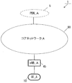
- FIG. 1 is a diagram for explaining an outline of a mobile communication system in the present embodiment.
- the mobile communication system 1 includes mobile terminal apparatuses UE_A10, eNB_A45, a core network_A90, and PDN_A5.
- UE_A10 may be a terminal device that can be wirelessly connected, and may be UE (User equipment), ME (Mobile equipment), or MS (Mobile equipment).
- UE User equipment
- ME Mobile equipment
- MS Mobile equipment
- the UE_A10 may be a CIoT terminal.
- the CIoT terminal is an IoT terminal that can be connected to the core network A90, and the IoT terminal includes a mobile phone terminal such as a smartphone, and may be various IT devices such as a personal computer and a sensor device.
- UE_A10 may request a connection optimized for CIoT terminals based on UE_A10 policies or network requests, or may request a conventional connection .
- UE_A10 may be set as a terminal device that connects to core network_A90 only by a communication procedure optimized for CIoT terminals in advance at the time of shipment.
- core network_A90 is an IP mobile communication network operated by a mobile operator.
- the core network_A90 may be a core network for a mobile communication operator that operates and manages the mobile communication system 1, or a core for a virtual mobile communication operator such as MVNO (Mobile Virtual Network Operator). It can be a network.
- the core network_A90 may be a core network for accommodating CIoT terminals.
- ENB_A45 is a base station constituting a radio access network used for UE_A10 to connect to core network_A90. That is, UE_A10 connects to core network_A90 using eNB_A45.
- core network_A90 is connected to PDN_A5.
- PDN_A5 is a packet data service network that provides a communication service to UE_A10, and may be configured for each service.
- a communication terminal is connected to the PDN, and UE_A10 can transmit and receive user data to and from the communication terminal arranged in PDN_A5.
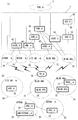
- Fig. 2 shows the first example of the configuration of the core network_90.
- the core network_A90 in Figure 2 (a) is HSS (Home Subscriber Server) _A50, AAA (Authentication, Authorization, Accounting) _A55, PCRF (Policy (enhanced Packet Data Gateway) _A65, SGW (Serving ⁇ Gateway) _A35, MME (Mobility Management Entity) _A40, SGSN (Serving GPRS Support Node) _A42.
- HSS Home Subscriber Server
- AAA Authentication, Authorization, Accounting
- PCRF Policy (enhanced Packet Data Gateway) _A65
- SGW Serving ⁇ Gateway
- MME Mobility Management Entity
- SGSN Serving GPRS Support Node
- the core network_A90 can be connected to a plurality of radio access networks (LTE AN_A80, WLAN ⁇ ANb75, WLAN ANa70, UTRAN_A20, GERAN_A25).
- LTE AN_A80, WLAN ⁇ ANb75, WLAN ANa70, UTRAN_A20, GERAN_A25 radio access networks
- the radio access network may be configured to be connected to a plurality of different access networks, or may be configured to be connected to any one access network. Furthermore, UE_A 10 can wirelessly connect to the radio access network.
- the access networks that can be connected by the WLAN access system are WLAN access network b (WLAN ANb75) connected to the core network via ePDG_A65, and WLAN access network a (WLAN ANa75) connected to PGW_A, PCRF_A60, and AAA_A55. Is configurable.
- each device is configured in the same manner as a conventional device in a mobile communication system using EPS, detailed description is omitted. Hereinafter, each device will be briefly described.
- PGW_A30 is connected to PDN_A5, SGW_A35, ePDG_A65, WLAN ANa70, PCRF_A60 and AAA_A55, and is a relay device that transfers user data as a gateway device for PDN_A5 and core network_A90.
- SGW_A35 is connected to PGW30, MME_A40, LTE AN80, SGSN_A42 and UTRAN_A20, and relay device that transfers user data as a gateway device between core network_A90 and 3GPP access network (UTRAN_A20, GERAN_A25, LTE AN_A80) It is.
- MME_A40 is connected to SGW_A35, LTE AN80, and HSS_A50, and is an access control device that performs location information management and access control of UE_A10 via LTE AN80.
- the core network_A90 may be configured to include a plurality of location management devices. For example, a location management device different from MME_A40 may be configured. A location management device different from MME_A40 may be connected to SGW_A35, LTE AN80, and HSS_A50 in the same manner as MME_A40.
- the MMEs may be connected to each other. Thereby, transmission / reception of the context of UE_A10 may be performed between MMEs.
- HSS_A50 is connected to MME_A40 and AAA_A55, and is a management node that manages subscriber information.
- the subscriber information of HSS_A50 is referred to at the time of access control of MME_A40, for example. Further, the HSS_A50 may be connected to a location management device different from the MME_A40.
- AAA_A55 is connected to PGW30, HSS_A50, PCRF_A60, and WLAN ANa70, and performs access control for UE_A10 connected via WLAN ANa70.
- PCRF_A60 is connected to PGW_A30, WLAN ANA75, AAA_A55, and PDN_A5, and performs QoS management for data delivery. For example, the QoS of the communication path between UE_A10 and PDN_A5 is managed.
- EPDG_A65 is connected to PGW30 and WLANWANb75, and delivers user data as a gateway device between core network_A90 and WLAN ANb75.
- SGSN_A42 is connected to UTRAN_A20, GERAN_A25 and SGW_A35 and is a control device for location management between 3G / 2G access network (UTRAN / GERAN) and LTE access network (E-UTRAN). Furthermore, SGSN_A42 has a PGW and SGW selection function, a UE time zone management function, and an MME selection function at the time of handover to E-UTRAN.
- each radio access network includes devices (for example, base station devices and access point devices) to which UE_A 10 is actually connected.
- devices for example, base station devices and access point devices
- a device used for connection a device adapted to a radio access network can be considered.
- LTE-AN80 is configured to include eNB_A45.
- eNB_A45 is a radio base station to which UE_A10 is connected in the LTE access system
- LTE-AN_A80 may be configured to include one or a plurality of radio base stations.
- WLAN AAN70 is configured to include WLAN APa72 and TWAG_A74.
- WLAN APa72 is a wireless base station to which UE_A10 connects with a WLAN access system that is reliable to the operator operating the core network_A90
- WLAN ANa70 is configured to include one or more wireless base stations It's okay.
- TWAG_A74 is a gateway device between the core network_A90 and the WLAN AAN70. Further, the WLAN APA 72 and the TWAG_A 74 may be configured by a single device.
- WLAN ANb75 includes WLAN ⁇ ⁇ APb76.
- WLAN APb76 is a wireless base station to which UE_A10 is connected in the WLAN access system when a trust relationship is not established with the operator operating the core network_A90, and WLAN ⁇ ⁇ ANb75 has one or more wireless base stations May be included.
- WLAN ANb75 is connected to core network_A90 using ePDG_A65, which is a device included in core network_A90, as a gateway.
- ePDG_A65 has a security function to ensure safety.
- UTRAN_A20 includes RNC (Radio Network Controller) _A24 and eNB (UTRAN) _A22.
- eNB (UTRAN) _A22 is a radio base station to which UE_A 10 is connected by UTRA (UMTS Terrestrial Radio Access), and UTRAN_A20 may be configured to include one or a plurality of radio base stations.
- the RNC_A24 is a control unit that connects the core network_A90 and the eNB (UTRAN) _A22, and the UTRAN_A20 may be configured to include one or a plurality of RNCs.
- the RNC_A24 may be connected to one or more eNB (UTRAN) _A22.
- the RNC_A24 may be connected to a radio base station (BSS (Base Station Subsystem) _A26) included in the GERAN_A25.
- BSS Base Station Subsystem
- GERAN_A25 includes BSS_A26.
- BSS_A26 is a radio base station to which UE_A10 is connected by GERA (GSM (registered trademark) / EDGE radio access), and GERAN_A25 may be configured by one or a plurality of radio base stations BSS. A plurality of BSSs may be connected to each other. BSS_A26 may be connected to RNC_A24.
- the core network_A90 may have the configuration shown in FIG.
- the core network_A90 in FIG. 3 (a) is composed of C-SGN (CIoT Serving Gateway Node) _A95 and HSS_A50.
- the core network_A90 includes AAA_A55 and / or PCRF_A60 and / or ePDG_A65 and / or SGSN_A42 in the core network_A90 in order to provide connectivity with access networks other than LTE. May be.
- C-SGN_A95 may be a node that plays the role of MME_A40, SGW_A35, and PGW_A30 in FIG.
- C-SGN_A95 may be a node for CIoT terminals.
- C-SGN_A95 may have a gateway device function between PDN_A and core network_A90, a gateway device function between core network_A90 and CIOTAN_A100, and a location management function of UE_A10.
- UE_A10 is connected to the core network_A90 via the radio access network CIOT AN_A100.
- Fig. 3 (b) shows the configuration of CIOT AN_A100.
- CIOT AN_A100 may be configured to include eNB_A45.
- ENB_A45 included in CIOT AN_A100 may be the same base station as eNB_A45 included in LTE AN_A80.
- eNB_A45 included in CIOT AN_A100 may be a base station for CIoT different from eNB_A45 included in LTE AN_A80.
- first core network and / or the second core network may be configured by a system optimized for IoT.
- UE_A10 being connected to each radio access network means being connected to a base station device, an access point, etc. included in each radio access network. Also via a base station device or access point.
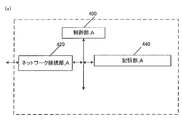
- FIG. 4 (a) shows the device configuration of eNB_A45.
- the eNB_A45 includes a network connection unit_A420, a control unit_A400, and a storage unit_A440.
- the network connection unit _A420 and the storage unit _A440 are connected to the control unit _A400 via a bus.
- Control unit_A400 is a functional unit for controlling eNB_A45.
- the control unit_A400 implements various processes by reading and executing various programs stored in the storage unit_A440.
- the network connection unit_A420 is a functional unit for the eNB_A45 to connect to the MME_A40 and / or SGW_A35 or C-SGN_A95. Furthermore, the network connection unit_A420 is a transmission / reception function unit in which the eNB_A45 transmits / receives user data and / or control data from the MME_A40 and / or SGW_A35 or C-SGN_A95.
- Storage unit_A440 is a functional unit that stores programs and data necessary for each operation of eNB_A45.
- the storage unit 640 includes, for example, a semiconductor memory, an HDD (Hard Disk Drive), or the like.
- the storage unit _A440 stores at least identification information and / or control information and / or flags and / or parameters included in control messages transmitted and received in the attach procedure and data transmission procedure described in 1.3 and 1.4. Good.
- eNB_A45 is provided with the transmission / reception part which transmits / receives UE_A10 and control information and / or user data. Further, an external antenna is connected to the transmission / reception unit.
- FIG. 6 (a) shows the device configuration of MME_A40.
- the MME_A 40 includes a network connection unit_B620, a control unit_B600, and a storage unit_B640.
- the network connection unit_B620 and the storage unit_B640 are connected to the control unit_B600 via a bus.
- Control unit_B600 is a functional unit for controlling MME_A40.
- the control unit_B600 implements various processes by reading and executing various programs stored in the storage unit_B640.
- the network connection unit_B620 is a functional unit for the MME_A40 to connect with the HSS_A50 and / or SGW_A35. Furthermore, the network connection unit_B620 is a transmission / reception function unit that allows the MME_A40 to transmit and receive user data and / or control data from the HSS_A50 and / or SGW_A35.
- Storage unit_B640 is a functional unit that stores programs and data necessary for each operation of MME_A40.
- the storage unit_B640 is configured by, for example, a semiconductor memory, an HDD (Hard Disk Drive), or the like.
- the storage unit _B640 stores at least identification information and / or control information and / or flags and / or parameters included in control messages transmitted and received in the attach procedure and data transmission procedure described in 1.3 and 1.4. Good.
- the storage unit_B640 stores an MME context 642, a security context 648, and MME emergency configuration data 650, as shown in the figure.
- the MME context includes an MM context and an EPS bearer context.
- the MME context may be composed of an EMM context and an ESM context.
- the MM context is an EMM context
- the EPS bearer context may be an ESM context.
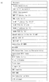
- Fig. 7 (b), Fig. 8 (b) and Fig. 9 (b) show information elements of MME context stored for each UE.
- the MME context stored for each UE is IMSI, IMSI-unauthenticated-indicator, MSISDN, MM State, GUTI, ME Identity, Tracking Area List, TAI of last TAU, ECGI (E-UTRAN Cell Global Identity), E-UTRAN Cell Identity Identity, CSG ID, CSG membership, Access mode, Authentication Vector, UE Radio Access Capability, MS Classmark 2, MS Classmark 3, Supported Codecs, UE Network Capability, MS Network Capability, UE Specific DRX Parameters , Selected NAS Algorithm, eKSI, K_ASME, NAS Keys and COUNT, Selected CN operator ID, Recovery, Access Restriction, ODB for PS parameters, APN-OI Replacement, MME IP address for S11, MME TEID for S11, S-GW for S11 / S4,
- IMSI is the user's permanent identification information. Same as IMSI stored in HSS_A50.
- IMSI-unauthenticated-indicator is instruction information indicating that this IMSI is not authenticated.
- MSISDN represents the phone number of the UE. MSISDN is indicated by the storage part of HSS_A50.
- MM State indicates the MME mobility management state.
- This management information includes the ECM-IDLE state in which the connection between the eNB and the core network is released, the ECM-CONNECTED state in which the connection between the eNB and the core network is not released, or the MME stores the location information of the UE. No EMM-DEREGISTERED state.
- GUTI Globally Unique Unique Temporary Identity
- MME identification information GUMMEI: GloballyGlobalUnique MME Identifier
- M-TMSI UE identification information
- the ID of ME IdentityUE for example, IMEI / IMISV.
- Tracking Area List is a list of tracking area identification information assigned to the UE.
- TAI of last TAU is tracking area identification information indicated in the latest tracking area update procedure.
- ECGI is the latest UE cell identification information known to MME_A40.
- E-UTRAN Cell Identity Age indicates the elapsed time since the MME acquired ECGI.
- the CSG ID is identification information of a CSG (Closed Subscriber Group) operated by a recent UE as known by the MME.
- CSG membership is the latest UE CSG member information known to MME.
- CSG membership indicates whether the UE is a CSG member.
- Access mode is an access mode of a cell identified by ECGI, and may be identification information indicating that ECGI is a hybrid that allows access to both CSG and non-CSG UEs.
- Authentication Vector indicates a temporary AKA (Authentication and Key Agreement) of a specific UE that the MME follows.
- the Authentication Vector is composed of a random value RAND used for authentication, an expected response XRES, a key K_ASME, and a language (token) AUTN authenticated by the network.
- Radio Access Capability is identification information indicating the radio access capability of the UE.
- MS Classmark 2 is a 3G / 2G (UTRAN / GERAN) CS domain core network classmark. MS Classmark 2 is used when the UE supports SRVCC (Single Radio Voice Call Continuit) for GERAN or UTRAN.
- SRVCC Single Radio Voice Call Continuit
- MS Classmark 3 is the class mark of the GERAN CS domain wireless network. MS Classmark 3 is used when the UE supports SRVCC (Single Radio Voice Call Continuit) for GERAN.
- SRVCC Single Radio Voice Call Continuit
- SupportedcsCodecs is a list of codes supported by CS domain. This list is used when the UE supports SRVCC for GERAN or UTRAN.
- UE Network Capability includes security algorithms and key derivation functions supported by the UE.
- MS Network Capability is information including at least one piece of information necessary for SGSN for UE having GERAN and / or UTRAN functions.
- UE Specific DRX Parameters are parameters used to determine the UE DRX (Discontinuous Reception) cycle length.
- DRX is a function for switching the UE to a low power consumption state when there is no communication for a certain period of time in order to reduce the power consumption of the battery of the UE as much as possible.
- “Selected NAS Algorithm” is a selected security algorithm of NAS (Non-Access Stream).
- EKSI is a set of keys indicating K_ASME. Whether or not to use a security key acquired by UTRAN or E-UTRAN security authentication may be indicated.
- K_ASME is an E-UTRAN key hierarchy key generated based on the encryption key CK (Cipher Key) and the complete key IK (Integrity Key).
- NAS Keys and COUNT consists of key K_NASint, key K_NASenc and NAS COUNT parameter.
- Key K_NASint is a key for encryption between UE and MME
- key K_NASenc is a key for security protection between UE and MME.
- NAS COUNT is a count that starts counting when a new key is set when security between the UE and the MME is established.
- the “selected CN” operator ID is identification information of the selected core network operator used for sharing the network among operators.
- Recovery is identification information indicating whether the HSS performs database restoration.
- Access Restriction is registration information for access restriction.
- ODB for PS parameters indicate the state of ODB (operator determined) barring.
- ODB is an access rule determined by a telecommunications carrier (operator).
- APN-OI Replacement is a domain name that replaces APN when constructing a PGW FQDN to perform DNS resolution. This alternate domain name applies to all APNs.
- MME IP address for S11 is the IP address of MME used for the interface with SGW.
- MME TEID for S11 is a TEID (Tunnel Endpoint Identifier) used in the interface with SGW.
- S-GW IP address for S11 / S4 is the IP address of SGW used at the interface between MME and SGW or between SGSN and MME.
- S GW TEID for S11 / S4 is the TEID of SGW used at the interface between MME and SGW or between SGSN and MME.
- SGSN IP address for S3 is the IP address of SGSN used for the interface between MME and SGSN.
- SGSN TEID for S3 is the SGSN TEID used in the interface between MME and SGSN.
- EnodeB Address in “Use” for “S1-MME” is the IP address of eNB that was recently used in the interface between MME and eNB.
- ENB UE S1AP ID is identification information of UE within eNB.
- MME UE S1AP ID is identification information of UE in MME.
- Subscribed UE-AMBR indicates the maximum value of MBR (Maximum Bit Rate) for uplink and downlink communication for sharing all Non-GBR (Guaranteed Bit Rate) bearers (non-guaranteed bearers) according to user registration information.
- MBR Maximum Bit Rate
- Non-GBR Guard Bit Rate
- UE-AMBR indicates the maximum value of MBR of uplink communication and downlink communication recently used to share all Non-GBR bearers (non-guaranteed bearers).
- EPS Subscribed ”Charging Characteristics indicates the charging characteristics of the UE.
- EPS Subscribed Charging Characteristics may indicate registration information such as normal, prepaid, fixed charge rate, or immediate billing.
- Subscribed RFSP Index is an index for a specific RRM configuration in E-UTRAN obtained from HSS.
- RFSP Index In Use is an index for a specific RRM configuration in E-UTRAN that has been used recently.
- Trace reference is identification information for identifying a specific trace record or a set of records.
- Trace type indicates the type of trace. For example, the type that HSS traces and / or the type that MME, SGW, or PGW traces may be indicated.
- Trigger ID is identification information that identifies the component that starts the trace.
- OMCM Identity is identification information that identifies the OMC that received the traced record.
- URRP-MME is identification information indicating that the UE activity notification from the MME is requested by the HSS.
- CSG Subscription Data is a related list of roaming destination PLMN (VPLMN) CSG ID and roaming destination equivalent PLMN.
- Each CSG ID may be associated with an expiration date indicating the expiration date of the CSG ID or an absent date indicating that there is no expiration date.
- the CSG ID may be used for a specific PDN connection via LIPA.
- Subscribed Periodic RAU / TAU Timer is a periodic RAU and / or TAU timer.
- MPS CS priority indicates that the UE is registered with eMLPP or 1x RTT priority service in the CS domain.
- MPS EPS priority is identification information indicating that it is registered in the MPS within the EPS domain.
- Voice Support Match Indicator indicates whether the UE's radio capabilities are compatible with the network configuration. For example, it indicates whether the SRVCC support by the UE matches the support for network voice calls.
- Homogenous Support of IMS Voice over PS Sessions for MME is instruction information indicating for each UE whether to support IMS voice calls over PS sessions.
- Homogenous Support of IMS Voice over PS Sessions for MME supports all IMS (IP Multimedia Subsystem) voice calls over PS (Packet Switched) sessions with all TAs (Tracking Area) managed by MME. ”And“ Not Supported ”indicating that there is no TA supporting IMS voice call on the PS session.
- IMS IP Multimedia Subsystem
- PS Packet Switched
- TAs Track Area
- the MME notifies the HSS of this instruction information. do not do.
- Fig. 10 (c) shows the information elements included in the MME context stored in the transmit / receive enabled state.
- the transmission / reception enabled state will be described later.
- the MME stored in the transmit / receive enabled state may be stored for each PDN connection.
- the MME context stored in the send / receive enabled state is APN Use, APN Restriction, APN Subscribed, PDN Type, IP Address, EPS PDN Charging Characteristics, APN-OI Replacement, SIPTO permissions, Local Home Network ID , LIPA permissions, WLAN offloadability, VPLMN Address Allowed, PDN GW Address Address Use (control information), PDN GW TEID for S5 / S8 (control information), MS Info Change Reporting Action, CSG Information Reporting Action, EPS Include subscribed QoS profile, Subscribed APN-AMBR, APN-AMBR, PDN GW GRE Key, forlink traffic (user data), Default bearer, and low access priority.
- APN in ⁇ Use indicates the recently used APN.
- This APN is composed of APN network identification information and default operator identification information.
- APN Restriction indicates the restriction of the combination of APN types for the APN associated with this bearer context. That is, it is information that limits the number of APNs that can be established and the type of APN.
- APINscribedSubscribed means registered APN received from HSS.
- PDN Type indicates the IP address type.
- the PDN type indicates IPv4, IPv6 or IPv4v6.
- IP Address indicates an IPv4 address or IPv6 Prefix.
- the IP address may store both IPv4 and IPv6 prefixes.
- EPS PDN Charging Characteristics indicates billing characteristics. EPS PDN Charging Characteristics may indicate, for example, normal, prepaid, fixed charge rate, or instant billing.
- APN-OI Replacement is a proxy domain name of APN that has the same role as APN-OI Replacement registered for each UE. However, the priority is higher than APN-OI Replacement for each UE.
- SIPTO permission indicates permission information for SIPTO (Selected IP Traffic Offload) of traffic using this APN. Specifically, SIPTO permissions prohibits the use of SIPTO, permits the use of SIPTO outside of the local network, permits the use of SIPTO in networks that include the local network, or allows only the local network to use SIPTO. Identify that you are allowed to use
- Local Home Network ID indicates identification information of the home network to which the base station belongs when SIPTO (SIPTO @ LN) using the local network is available.
- LIPA permissions is identification information indicating whether this PDN can be accessed via LIPA.
- the LIPA-permissions may be LIPA-prohibited that does not allow LIPA, or LIPA-only that allows LIPA only, or LIPA-conditional that permits LIPA by condition.
- WLAN offloadability is identification information indicating whether traffic connected by this APN can be offloaded to a wireless run using a link function between the wireless run and 3GPP, or whether a 3GPP connection is maintained.
- WLAN load ability may be divided for each RAT type. Specifically, different WLAN offload ability may exist between LTE (E-UTRA) and 3G (UTRA).
- VPLMN Address Allowed indicates that the UE is allowed to use only the HPLMN domain (IP address) PGW in the roaming PLMN (VPLMN), or the PGW in the VPLMN domain is connected using this APN. Indicates whether it will be added.
- IP address IP address
- PGW Address in Use indicates the latest IP address of the PGW. This address is used when transmitting a control signal.
- PDN GW TEID for S5 / S8 (control information) is a TEID used for transmission / reception of control information at the interface (S5 / S8) between SGW and PGW.
- MS Info Change Reporting Action is an information element indicating that it is necessary to notify the PGW that the user location information has been changed.
- CSG Information Reporting Action is an information element indicating that it is necessary to notify the PGW that the CSG information has been changed.
- Presence Reporting Area Action indicates that it is necessary to notify the change of whether or not the UE exists in the presence reporting area (Presence Reporting Area).
- This information element is divided into identification information of the presence report area and elements included in the presence report area.
- the EPS “subscribed” QoS profile shows the QoS parameters at the bearer level for the default bearer.
- Subscribed APN-AMBR is the maximum value of MBR (Maximum Bit Rate) for uplink and downlink communication for sharing all Non-GBR bearers (non-guaranteed bearers) established for this APN according to user registration information Indicates.
- MBR Maximum Bit Rate
- APN-AMBR is the maximum value of MBR (Maximum Bit ⁇ ⁇ Rate) for uplink and downlink communication to share all Non-GBR bearers (non-guaranteed bearers) established for this APN determined by PGW Indicates.
- PDN-GW-GRE-Key-for-link-traffic (user data) is a GRE (Generic Routing Encapsulation) key for uplink communication of user data at the interface between SGW and PGW.
- GRE Generic Routing Encapsulation
- Default bearer is EPS bearer identification information for identifying the default bearer in the PDN connection.
- Low access priority indicates that the UE requested a low access priority (low access priority) when the PDN connection is open.
- Fig. 11 (d) shows the MME context stored for each bearer.
- the MME context stored for each bearer is EPS Bearer ID, TI, S-GW IP address for S1-u, S-GW TEID for S1u, PDN GW TEID for S5 / S8, PDN GW IP Include address for S5 / S8, EPS bearer QoS, TFT.
- EPS Bearer ID is the only identification information that identifies EPS bearer for UE connection via E-UTRAN.
- TI is an abbreviation for Transaction Identifier, and is identification information that identifies a bidirectional message flow (Transaction).
- S-GW IP address for S1-u is the IP address of SGW used at the interface between eNB and SGW.
- S-GW TEID for S1u is the SGW TEID used at the interface between eNB and SGW.
- PDN GW TEID for S5 / S8 is PGW TEID for user data transmission of the interface between SGW and PGW.
- PDN “GW IP address” for “S5 / S8” is the IP address of PGW for user data transmission of the interface between SGW and PGW.
- EPS bearer QoS consists of QCI (QoS Class Identifier) and ARP (Allocation and Retention Priority).
- QCI indicates the class to which QoS belongs.
- QoS can be divided into classes according to the presence / absence of bandwidth control, allowable delay time, and packet loss rate.
- QCI includes information indicating priority.
- ARP is information indicating the priority related to maintaining a bearer.
- TFT Traffic Flow Template
- the information elements included in the MME context shown in FIGS. 7 to 11 are included in either the MM context 644 or the EPS bearer context 646.
- the MME context for each bearer shown in FIG. 11 (d) may be stored in the EPS bearer context, and other information elements may be stored in the MM context.
- the MME context stored in the transmit / receive enabled state shown in FIG. 10 (c) and the MME context for each bearer shown in FIG. 11 (d) may be stored in the EPS bearer context, and other information elements may be stored in the MM context. Good.
- the MME storage unit_B640 may store a security context 648.
- FIG. 12 (e) shows information elements included in the security context 648.
- FIG. 12 (e) shows information elements included in the security context 648.
- the security context consists of EPS AS security context and EPS NAS security context.
- the EPS AS security context is a context related to the security of the access layer (AS: Access Stream)
- the EPS NAS security context is a context related to the security of the non-access layer (NAS: Non-Access Stream).
- Fig. 12 (f) shows the information elements included in the EPS AS security context.
- the EPS AS security context includes a cryptographic key, Next Hop parameter (NH), Next Hop Chaining Counter parameter (NCC), and identifiers of the selected AS level cryptographic algorithms.
- Cryptographic key is an encryption key in the access layer.
- NH is an information element determined from K_ASME. It is an information element for realizing forward security.
- NCC is an information element associated with NH. This represents the number of vertical handovers that switch networks.
- Figure 12 (g) shows the information elements included in the EPS NAS security context.
- the EPS-NAS-security context may include K_ASME, UE-security-capabilitie, and NAS-COUNT.
- K_ASME is an E-UTRAN key hierarchy key generated based on keys CK and IK.
- UE Security Capabilitie is a set of identification information corresponding to the ciphers and algorithms used in the UE. This information includes information for the access layer and information for the non-access layer. Furthermore, if the UE supports access to UTRAN / GERAN, this information includes information for UTRAN / GERAN.
- NAS COUN is a counter that indicates the time during which K_ASME is operating.
- the security context 648 may be included in the MME context 642. Further, as shown in FIG. 6 (a), the security context 648 and the MME context 642 may exist separately.
- FIG. 12 (h) shows information elements stored in the MME emergency configuration data 650.
- the MME emergency configuration data is information used instead of the UE registration information acquired from the HSS.
- the MME emergency configuration data 650 includes em APN (Emergency Access Point Name), Emergency QoS profile, Emergency APN-AMBR, Emergency PDN GW identity, Non-3GPP HO Emergency PDN GW identity.
- [Em APN indicates the name of the access point used for emergency PDN connection.
- Emergency QoS profile indicates the QoS of the default bearer of em N APN at the bearer level.
- Emergency APN-AMBR indicates the maximum value of MBR for uplink and downlink for sharing Non-GBR bearer (non-guaranteed bearer) established for em APN. This value is determined by PGW.
- Emergency PDN GW identity is PGW identification information statically set for em APN. This identification information may be an FQDN or an IP address.
- Non-3GPP HO Emergency PDN GW identity is PGW identification information that is statically set for em APN when the PLMN supports handover to an access network other than 3GPP.
- This identification information may be an FQDN or an IP address.
- the MME_A 40 may manage the connection state for the UE while synchronizing with the UE.
- FIG. 13 (a) shows the device configuration of SGW_A35.
- the SGW_A35 includes a network connection unit_C1320, a control unit_C1300, and a storage unit_C1340.
- the network connection unit _C1320 and the storage unit _C1340 are connected to the control unit _C1300 via a bus.
- Control unit_C1300 is a functional unit for controlling SGW_A35.
- the control unit_C1300 implements various processes by reading and executing various programs stored in the storage unit_C1340.
- the network connection unit_C1320 is a functional unit for the SGW_A35 to connect to the MME_A40 and / or PGW_A30 and / or SGSN_A42. Furthermore, the network connection unit_C1320 is a transmission / reception function unit in which the SGW_A35 transmits / receives user data and / or control data from the MME_A40 and / or PGW_A30 and / or SGSN_A42.
- Storage unit_C1340 is a functional unit that stores programs and data necessary for each operation of SGW_A35.
- the storage unit_C1340 includes, for example, a semiconductor memory, an HDD (Hard Disk Disk Drive), or the like.
- the storage unit _C1340 stores at least identification information and / or control information and / or flags and / or parameters included in control messages transmitted and received in the attach procedure and data transmission procedure described in 1.3 and 1.4. Good.
- Storage unit_C1340 stores EPS bearer context 1342 as shown in the figure.
- the EPS bearer context includes one stored for each UE, one stored for each PDN, and one stored for each bearer.
- Fig. 14 (b) shows the information elements of EPS bearer context stored for each UE.
- the EPS bearer context stored for each UE is IMSI, MSI-unauthenticated-indicator, ME Identity, MSISDN, Selected CN CN operator id, MME TEID for S11, MME IP address for S11, S-GW TEID for S11 / S4, S-GW IP address for S11 / S4, SGSN IP address for S4, SGSN TEID for S4, Trace reference, Trace type, Trigger ID, OMC identity, Last known Cell Id, Last known Cell Include Id age.
- IMSI is the user's permanent identification information. Equivalent to IMSI of HSS_A50.
- IMSI-unauthenticated-indicator is instruction information indicating that this IMSI is not authenticated.
- ME Identity is UE identification information, and may be, for example, IMEI / IMISV.
- MSISDN represents the basic phone number of the UE. MSISDN is indicated by the storage part of HSS_A50.
- Selected CN operator “id” is identification information of the selected core network operator used for sharing the network among operators.
- MME TEID for S11 is the MME TEID used in the interface between MME and SGW.
- MME IP address for S11 is the MME IP address used in the interface between MME and SGW.
- S-GW TEID for S11 / S4 is the TEID of SGW used in the interface between MME and SGW or the interface between SGSN and SGW.
- S-GW IP address for S11 / S4 is the IP address of SGW used in the interface between MME and SGW or the interface between SGSN and SGW.
- SGSN IP address for S4 is the IP address of SGSN used in the interface between SGSN and SGW.
- SGSN TEID for S4 is the SGSN TEID used in the interface between SGSN and SGW.
- Trace reference is identification information for identifying a specific trace record or a set of records.
- Race ⁇ ⁇ Type indicates the type of trace. For example, the type that HSS traces and / or the type that MME, SGW, or PGW traces may be indicated.
- Trigger ID is identification information that identifies the component that starts the trace.
- OMCM Identity is identification information that identifies the OMC that received the traced record.
- “Last known Cell ID” is the latest location information of the UE notified from the network.
- Last known Cell ID is information indicating the period from when the Last known Cell ID is stored.
- the EPS bearer context includes an EPS bearer context stored in a transmit / receive enabled state.
- the transmission / reception enabled state will be described later.
- the EPS bearer context stored in the transmission / reception enabled state may be stored for each PDN connection.
- FIG. 15 (c) shows an EPS bearer context stored in a transmit / receive enabled state.
- the EPS bearer context stored in the transmit / receive enabled state is APN Use, EPS PDN Charging Characteristics, P-GW Address in Use (control information), P-GW TEID for S5 / S8 (control information) , P-GW Address in Use (user data), P-GW GRE Key for uplink (user data), S-GW IP address for S5 / S8 (control information), S-GW TEID for S5 / S8 (control information) , S GW Address in Use (user data), S-GW GRE Key for downlink traffic (user data), Default Bearer are included.
- APN in ⁇ Use indicates the recently used APN.
- This APN is composed of APN network identification information and default operator identification information. This information is information acquired from the MME or SGSN.
- EPS PDN Charging Characteristics indicates billing characteristics. EPS PDN Charging Characteristics may indicate, for example, normal, prepaid, fixed charge rate, or instant billing.
- P-GW Address in Use is the IP address of the PGW that was used when the SGW recently sent control information.
- P-GW TEID for S5 / S8 (control information) is an interface between SGW and PGW, and is TEGW of PGW used for transmission of control information.
- P-GW In Use is the IP address of the PGW that SGW used recently when sending user data.
- P-GW GRE Key for uplink (user data) is a GRE key for user data uplink communication of the interface between SGW and PGW.
- S-GW IP address for S5 / S8 (control information) is the IP address of SGW used for the interface of control information between SGW and PGW.
- S-GW TEID for S5 / S8 (control information) is the TEID of SGW used for the interface of control information between GW and PGW.
- S GW Address Use is the IP address of the SGW that was recently used by the SGW to send user data.
- S-GW GRE Key downlink traffic (user data) is an uplink GRE key used for user data interface between SGW and PGW.
- Default Bearer is identification information for identifying the default bearer in the PDN connection when the PDN connection is established.
- EPS bearer context of SGW includes EPS bearer context for each bearer.
- FIG. 15 (d) shows an EPS bearer context for each bearer.
- EPS bearer context for each bearer is EPS Bearer Id, TFT, P-GW Address in Use (user data), P-GW TEID for S5 / S8 (user data), S-GW IP address for S5 / S8 (user data), S-GW TEID for S5 / S8 (user data), S-GW IP address for S1-u, S12 and S4 (user data), S-GW TEID for S1-u, S12 and S4 (user data), eNodeB IP address for S1-u, eNodeB TEID for S1-u, RNC IP address for S12, RNC TEID for S12, SGSN IP address for S4 (user data), SGSN TEID for S4 (user data) , EPS Bearer QoS, Charging Id.
- EPS Bearer Id is the only identification information that identifies EPS bearers for UE connections via E-UTRAN. That is, it is identification information for identifying a bearer.
- TFT indicates all packet filters associated with the EPS bearer.
- PP-GW In ⁇ ⁇ ⁇ Use is the interface between SGW and PGW, and is the IP address of the PGW that was recently used for user data transmission.
- P-GW TEID for S5 / S8 (user data) is the PGW TEID for user data interface between SGW and PGW.
- S-GW IP address for S5 / S8 (user data) is the IP address of SGW for user data received from PGW.
- S-GW TEID for S5 / S8 (user data) is SGW's TEID for user data interface between SGW and PGW.
- S-GW IP address for S1-u, S12 and S4 are SGW IP addresses used at the interface between SGW and 3GPP access network (LTE access network or GERAN / UTRAN).
- S-GW TEID for S1-u, S12 and ⁇ ⁇ ⁇ S4 (user data) are SGW TEIDs used at the interface between SGW and 3GPP access network (LTE access network or GERAN / UTRAN).
- ENodeB IP address for S1-u is the IP address of eNB used for transmission between SGW and eNB.
- ENodeB TEID for S1-u is the eNB TEID used for transmission between SGW and eNB.
- RNC IP address for S12 is the RNC IP address used for the interface between SGW and UTRAN.
- RNC TEID for S12 is the RNC TEID used for the interface between SGW and UTRAN.
- SGSN IP address for S4 (user data) is an IP address of SGSN used for transmission of user data between SGW and SGSN.
- SGSN TEID for S4 (user data) is the SGSN TEID used to transmit user data between SGW and SGSN.
- EPS Bearer QoS represents the QoS of this bearer and may include ARP, GBR, MBR, and QCI.
- ARP is information indicating the priority related to maintaining a bearer.
- GBR Guaranteed Bit Bit Rate
- MBR Maximum Bit Bit Rate
- QCI can be divided into classes according to the presence / absence of bandwidth control, allowable delay time, packet loss rate, and the like. QCI includes information indicating priority.
- Charging Id is identification information for recording the billing generated by SGW and PGW.
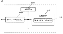
- FIG. 16 (a) shows the device configuration of PGW_A30.
- the PGW_A 30 includes a network connection unit_D1620, a control unit_D1600, and a storage unit_D1640.
- the network connection unit _D1620 and the storage unit _D1640 are connected to the control unit _D1600 via a bus.
- Control unit_D1600 is a functional unit for controlling PGW_A30.
- the control unit_D1600 implements various processes by reading and executing various programs stored in the storage unit_D1640.
- the network connection unit_D1620 is a functional unit for the PGW_A30 to connect to the SGW_A35 and / or PCRF_A60 and / or ePDG_A65 and / or AAA_A55 and / or GW_A74.
- the network connection unit_D1620 is a transmission / reception function unit in which the PGW_A30 transmits / receives user data and / or control data from / to the SGW_A35 and / or PCRF_A60 and / or ePDG_A65 and / or AAA_A55 and / or GW_A74.
- Storage unit_D1640 is a functional unit that stores programs and data necessary for each operation of PGW_A30.
- the storage unit_D1640 is configured by, for example, a semiconductor memory, an HDD (Hard Disk Disk Drive), or the like.
- the storage unit_D1640 may store at least identification information and / or control information and / or flags and / or parameters included in a control message transmitted and received in an attach procedure and a data transmission procedure described later.
- the storage unit_D1640 stores the EPS bearer context 1642 as shown in the figure.
- EPS bearer context what is stored for each UE, what is stored for each APN, what is stored in a transmit / receive enabled state, and what is stored for each bearer are separately stored. May be.
- FIG. 17 (b) shows information elements included in the EPS bearer context stored for each UE.
- EPS bearer context stored for each UE includes IMSI, IMSI-unauthenticated-indicator, ME Identity, MSISDN, Selected CN operator id, RAT type, Trace reference, Trace type, Trigger id, OMC identity. Including.
- IMSI is identification information assigned to a user who uses the UE.
- IMSI-unauthenticated-indicator is instruction information indicating that this IMSI is not authenticated.
- ME Identity is the UE ID, and may be, for example, IMEI / IMISV.
- MSISDN represents the basic phone number of the UE. MSISDN is indicated by the storage part of HSS_A50.
- the “selected CN” operator ID is identification information of the selected core network operator used for sharing the network among operators.
- RAT type indicates the UE's recent RAT (Radio Access Technology).
- the RAT type may be, for example, E-UTRA (LTE) or UTRA.
- Trace reference is identification information for identifying a specific trace record or a set of records.
- Trace type indicates the type of trace. For example, the type that HSS traces and / or the type that MME, SGW, or PGW traces may be indicated.
- Trigger ID is identification information that identifies the component that starts the trace.
- OMCM Identity is identification information that identifies the OMC that received the traced record.
- Fig. 17 (c) shows the EPS bearer context stored for each APN.
- the EPS bearer context stored for each APN of the PGW storage unit includes APN in use and APN-AMBR.
- APN in ⁇ Use indicates the recently used APN.
- This APN is composed of APN network identification information and default operator identification information. This information is obtained from SGW.
- APN-AMBR indicates the maximum value of MBR (Maximum Bit Rate) of uplink communication and downlink communication for sharing all Non-GBR bearers (non-guaranteed bearers) established for this APN.
- MBR Maximum Bit Rate
- Fig. 18 (d) shows the EPS bearer context stored in the transmit / receive enabled state.
- the transmission / reception enabled state will be described later.
- the EPS bearer context stored in the transmission / reception enabled state may be stored for each PDN connection.
- the EPS bearer context stored in the transmit / receive enabled state is IP Address, PDN type, S-GW Address In use (control information), S-GW TEID for S5 / S8 (control information), S- GW Address In use (user data), S-GW GRE Key for downlink traffic (user data), P-GW IP address for S5 / S8 (control information), P-GW TEID for S5 / S8 (control information), P -GW Address in ⁇ ⁇ ⁇ Use (user data), P-GW GRE Key for uplink traffic (user data), MS Info Change Reporting support indication, MS Info Change Reporting Action, CSG Information Reporting Action, Presence Reporting Area Action, BCM, Default Bearer Include EPS PDN Charging Characteristics.
- IP Address indicates the IP address to which the UE is assigned in the transmit / receive enabled state.
- the IP address may be IPv4 and / or IPv6 prefix.
- PDN type indicates the type of IP address.
- PDN type indicates, for example, IPv4, IPv6, or IPv4v6.
- S-GW Address in Use is the IP address of the SGW that is recently used to transmit control information.
- S-GW TEID for S5 / S8 (control information) is the TEID of SGW used for transmission / reception of control information between SGW and PGW.
- S-GW In Use is the IP address of the SGW that was recently used for sending user data on the interface between the SGW and the PGW.
- S-GW GRE Key for downlink traffic is an interface between SGW and PGW, and is a GRE key assigned for use in downlink communication of user data from PGW to SGW.
- P-GW IP address for S5 / S8 (control information) is the IP address of the PGW used for control information communication.
- P-GW TEID for S5 / S8 (control information) is PGW TEID for communication of control information using the interface between SGW and PGW.
- P-GW Address in Use is the IP address of the PGW that was recently used to transmit user data using the interface between the SGW and the PGW.
- GRE Key for “uplink traffic” (user data) is a GRE key assigned for user data uplink communication between SGW and PGW, that is, transmission of user data from SGW to PGW.
- MS Info Change Reporting Reporting support indication indicates that the MME and / or SGSN supports the process of notifying the user location information and / or the user CSG information.
- MS Info Change Reporting Action is information indicating whether the MME and / or SGSN is requested to transmit a change in the user location information.
- CSG Information Reporting Action is information indicating whether the MME and / or SGSN is requested to transmit a change of the user's CSG information.
- This information includes (a) for CSG cells, (b) for hybrid cells where the user is a CSG member, (c) for hybrid cells where the user is not a CSG member, and combinations thereof. Shown separately.
- Presence Reporting Area Action indicates that it is necessary to notify the change of whether or not the UE exists in the presence reporting area (Presence Reporting Area).
- This information element is divided into identification information of the presence report area and elements included in the presence report area.
- BCM Breast Control Mode
- Default Bearer is identification information for identifying the default bearer included in the PDN connection when the PDN connection is established.
- EPS PDN Charging Characteristics is a charging characteristic.
- the charging characteristics may indicate, for example, normal (normal), prepaid, fixed charging rate, and immediate charging.
- FIG. 18 (e) shows an EPS bearer context stored for each EPS bearer.
- EPS bearer contexts are EPS Bearer Id, TFT, S-GW Address in Use (user data), S-GW TEID for S5 / S8 (user data), P-GW IP address for S5 / S8 (User data), P-GW TEID for S5 / S8 (User data), EPS Bearer QoS, Charging Id are included.
- EPS Bearer Id is identification information that identifies access via UE's E-UTRAN.
- TFT Traffic Flow Template
- S-GW Address in Use is the IP address of the SGW that was recently used for user data transmission.
- S-GW TEID for S5 / S8 (user data) is the SGW TEID for user data communication using the interface between SGW and PGW.
- P-GW IP address for S5 / S8 (user data) is the IP address of the PGW for user data received from the PGW.
- P-GW TEID for S5 / S8 (user data) is PGW TEID for user data communication between SGW and PGW.
- EPS Bearer QoS indicates the bearer QoS and may include ARP, GBR, MBR and QCI.
- ARP is information indicating the priority related to maintaining a bearer.
- GBR Guaranteed Bit Bit Rate
- MBR Maximum Bit Bit Rate
- QCI can be divided into classes according to the presence / absence of bandwidth control, allowable delay time, packet loss rate, and the like. QCI includes information indicating priority.
- Charging Id is billing identification information for identifying a record related to billing generated by SGW and PGW.
- FIG. 19 (a) shows a device configuration of C-SGN_A95.
- C-SGN_A95 includes a network connection unit_E1920, a control unit_E1900, and a storage unit_E1940.
- the network connection unit_E1920 and the storage unit_E1940 are connected to the control unit_E1900 via a bus.
- Control unit_E1900 is a functional unit for controlling C-SGN_A95.
- the control unit_E1900 realizes various processes by reading and executing various programs stored in the storage unit_E1940.
- Network connection unit_E1920 is a functional unit for C-SGN_A95 to connect with eNB_A45 and / or HSS_A50 and / or PDN_A5. Further, the network connection unit_E1920 is a transmission / reception function unit in which the C-SGN_A95 transmits / receives user data and / or control data from the eNB_A45 and / or HSS_A50 and / or PDN_A5.
- Storage unit_E1940 is a functional unit that stores programs and data necessary for each operation of C-SGN_A95.
- the storage unit_E1940 is configured by, for example, a semiconductor memory, an HDD (Hard Disk Disk Drive), or the like.
- the storage unit _E 1940 stores at least identification information and / or control information and / or flags and / or parameters included in control messages transmitted and received in the attach procedure and data transmission procedure described in 1.3 and 1.4. Good.
- the storage unit_E1940 stores a context A1942, a context B1944, a context C1946, and a context D1948 as shown in the figure.
- Context A 1942 may be the MME context 642 shown in FIG.
- the context B1944 may be the security context 648 shown in FIG. 6 (a).
- the context C1946 may be the MME emergency configuration data 650 shown in FIG. 6 (a).
- context D1948 may be the EPS bearer context 1342 shown in FIG. 13 (a).
- context E1950 may be the EPS bearer context 1642 shown in FIG.
- the IMSI may be included in each of the context A 1942, the context D 1948, and the context E 1950, or may be stored in any context.
- FIG. 20 (a) shows the device configuration of UE_A10.
- UE_A 10 includes a transmission / reception unit 2020, a control unit 2000, and a storage unit 2040.
- the transmission / reception unit 2020 and the storage unit 2040 are connected to the control unit 2000 via a bus.
- Control unit 2000 is a functional unit for controlling UE_A10.
- the control unit 2000 implements various processes by reading and executing various programs stored in the storage unit 2040.
- the transmission / reception unit 2020 is a functional unit for UE_A10 to connect to the LTE base station and connect to the IP access network.
- An external antenna 2010 is connected to the transmission / reception unit 2020.
- the storage unit 2040 is a functional unit that stores programs and data necessary for each operation of the UE_A10.
- the storage unit 2040 is configured by, for example, a semiconductor memory, an HDD (Hard Disk Drive), or the like.
- the storage unit 2040 stores the UE context 2042 as shown in the figure. Hereinafter, the information elements stored in the storage unit 2040 will be described.
- FIG. 21 (b) shows information elements included in the UE context stored for each UE.
- the UE context stored for each UE is IMSI, EMMEMState, GUTI, ME Identity, Tracking Area List, last visited TAI, Selected NAS Algorithm, Selected AS Algorithm, eKSI, K_ASME, NAS Keys and COUNT , TIN, UE Specific DRX Parameters, Allowed CSG list, Operator CSG list.
- IMSI is the permanent identification information of the subscriber.
- EMMM State indicates the UE mobility management status.
- the EMM-REGISTERED registered state, registered state
- the EMM-DEREGISTERD unregistered state, deregistered state
- GUTI is an abbreviation for Globally Unique Unique Temporary Identity and is temporary identification information of UE.
- the GUTI includes MME identification information (GUMMEI: GloballyGlobalUnique MME Identifier) and UE identification information (M-TMSI) in the specific MME.
- GUMMEI GloballyGlobalUnique MME Identifier
- M-TMSI UE identification information
- ME Identity is the ID of ME, and may be, for example, IMEI / IMISV.
- Tracking Area List is a list of tracking area identification information assigned to the UE.
- “Last” visited ”TAI is tracking area identification information included in the Tracking” Area ”List, and is identification information of the latest tracking area visited by the UE.
- “Selected NAS” Algorithm is the selected security algorithm of the NAS.
- “Selected AS” Algorithm is a security algorithm selected by AS.
- EKSI is a set of keys indicating K_ASME. Whether or not to use a security key acquired by UTRAN or E-UTRAN security authentication may be indicated.
- K_ASME is an E-UTRAN key hierarchy key generated based on keys CK and IK.
- NAS Keys and COUNT is composed of key K_NASint, key K_NASenc and NAS COUNT.
- K_NASint is a key for encryption between UE and MME
- K_NASenc is a key for security protection between UE and MME.
- NAS COUNT is a count that starts counting when a new key is set when security between the UE and the MME is established.
- TIN Temporal Identity used in Next update
- RAU / TAU location information update procedure
- UE Specific DRX Parameters is the DRX (Discontinuous Reception) cycle length of the selected UE.
- the Allowed CSG list is a list of PLMNs associated with the CSG ID of the member to which the authorized UE belongs under the control of both the user and the operator.
- the Operator CSG list is a list of PLMNs associated with the CSG ID of the member to which the authorized UE belongs under the control of the operator only.
- FIG. 21 (c) shows the UE context stored in the transmit / receive enabled state.
- the transmission / reception enabled state will be described later.
- the UE context stored in the transmit / receive enabled state may be stored for each PDN connection.
- the UE context stored in the transmission / reception enabled state includes APN in Use, APN-AMBR, Assigned PDN Type, IP Address, Default Bearer, and WLAN offloadability.
- APNAPin Use is a recently used APN. This APN may be composed of network identification information and default operator identification information.
- APN-AMBR indicates the maximum value of MBR for uplink and downlink for sharing Non-GBR bearer (non-guaranteed bearer). APN-AMBR is established for each APN.
- Assigned PDN Type is the type of PDN assigned from the network. Assigned PDN Type may be, for example, IPv4, IPv6, or IPv4v6.
- the IP address is an IP address assigned to the UE, and may be an IPv4 address or an IPv6 prefix.
- Default Bearer is EPS bearer identification information that identifies the default bearer in a PDN connection when a PDN connection is established.
- WLAN offloadability is WLAN offload permission information indicating whether to permit offload to WLAN using the interworking function between WLAN and 3GPP or to maintain 3GPP access.
- FIG. 21 (d) shows a UE context for each bearer stored in the UE storage unit.
- the UE context for each bearer includes EPS Bearer ID, TI, EPS bearer QoS, and TFT.
- EPS Bearer ID is bearer identification information.
- TI is an abbreviation for Transaction Identifier, and is identification information that identifies a bidirectional message flow (Transaction).
- TFT Traffic Flow Template
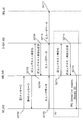
- the communication procedure in this embodiment includes an attach procedure (S2200), a transmission / reception means selection process (S2202), a first transmission / reception procedure (S2204), a second transmission / reception procedure (S2206), and a third transmission / reception procedure. (S2208).
- first transmission / reception procedure (S2204) and / or the second transmission / reception procedure (S2206) and / or the third transmission / reception procedure (S2208) can be omitted depending on conditions. Details of the conditions under which each procedure is executed and the processing will be described below.
- the connectionless communication in the present embodiment may be a communication in which UE_A 10 includes at least a process of including a NAS (Non Access Stratum) message including a data packet in an RRC (Radio R Source Control) message and transmitting it to eNB_A45. And or communication which transmits / receives a data packet between UE_A10 and eNB_A45, without establishing an RRC connection. And or communication which performs transmission / reception of a data packet in UE_A10 in an idle state may be sufficient.
- NAS Non Access Stratum
- RRC Radio R Source Control
- the active mode in the present embodiment means that UE_A10 and / or eNB_A45 and / or C-SGN_A95 establishes a DRB (Data Radio Bearer) and / or Default Bearer and / or PDN connection, and It may be a mode indicating a state where data can be transmitted and received.
- DRB Data Radio Bearer
- the DRB in the present embodiment may be a communication path such as a radio bearer established for transmission / reception of user data.
- the PDN connection in the present embodiment may be a connection for user data transmission / reception established between UE_A10 and C-SGN_A95.
- the idle mode in the present embodiment refers to UE_A10 and / or eNB_A45 and / or C-SGN_A95 releasing DRB and / or Default Bearer and / or PDN connection resources, and transmitting and receiving user data. It may be a mode indicating an incapable state.
- UE_A10, and / or eNB_A45, and / or C-SGN_A95 indicates that DRB, and / or Default Bearer, and / or PDN connection continue to be retained. It may be.
- the transmission / reception enabled state in the present embodiment is a state in which user data can be transmitted / received between UE_A 10 and PDN_A 5.
- the transmission / reception enabled state may be a state in which UE_A10 and / or PDN_A5, and / or eNB_A45, and / or C-SGN_A95 perform transmission / reception of user data.
- the transmission / reception enabled state may include a first mode, a second mode, a third mode, and a fourth mode.
- the first mode may be a mode in which UE_A10 and / or eNB_A45 and / or C-SGN_A95 transmits and receives user data without connection.
- the first mode may be a mode in which UE_A10 and / or eNB_A45 transmits and receives user data without establishing an RRC connection.
- the first mode may be a mode in which UE_A10 and / or C-SGN_A95 transmits and receives user data included in the NAS message.
- the first mode may be a mode in which UE_A10 and / or eNB_A45 transmits / receives user data included in the RRC message.
- the first mode may be a mode in which UE_A10 and / or eNB_A45 transmits and receives a NAS-PDU (Packet Data Unit) included in the RRC message.
- the NAS-PDU may be a control message including user data in a NAS message.
- the first mode may be a mode in which UE_A10 and / or eNB_A45 transmits / receives user data using SRB (Signalling Radio Bearer).
- SRB Synignalling Radio Bearer
- the first mode may be a mode in which UE_A10 and / or eNB_A45 transmits / receives user data using CRB (Control Signaling Radio Radio).
- CRB Control Signaling Radio Radio
- the SRB and CRB may be communication paths such as a radio bearer used for transmission / reception of control messages.
- the first mode may be a mode in which user data is transmitted and received using a bearer that UE_A10 and / or eNB_A45 and / or C-SGN_A95 transmits and receives control information.
- UE_A10 and / or eNB_A45 and / or C-SGN_A95 may transmit and receive user data using the first transmission / reception procedure.
- the second mode may be a mode in which UE_A10 and / or eNB_A45 and / or C-SGN_A95 establishes a connection and transmits / receives user data.
- the second mode may be a mode in which UE_A10 and / or eNB_A45 establishes an RRC connection and transmits / receives user data.
- the second mode may be a mode in which UE_A10 and / or eNB_A45 and / or C-SGN_A95 establishes a PDN connection and transmits / receives user data.
- the second mode may be a mode in which UE_A10 and / or eNB_A45 transmits and receives user data using DRB (Data Radio Bearer).
- DRB Data Radio Bearer
- the second mode may be a mode in which UE_A10 and / or eNB_A45 and / or C-SGN_A95 establishes a bearer for transmitting and receiving user data and transmits and receives user data.
- the second mode may be a mode in which UE_A10 and / or eNB_A45 and / or C-SGN_A95 establishes a default bearer and transmits / receives user data.
- the second mode may be a mode in which the context is maintained even when UE_A10 and / or eNB_A45 and / or C-SGN_A95 transitions to the idle mode.
- the second mode may be a mode in which UE_A10 and / or eNB_A45 can send and receive a NAS message in the third RRC message.
- UE_A10 and / or eNB_A45 and / or C-SGN_A95 may transmit and receive user data using the second transmission / reception procedure.
- the third mode may be a mode in which UE_A10, and / or eNB_A45, and / or C-SGN_A95 transmits and receives user data without connection, and is a mode in which a connection is established and user data is transmitted and received. Also good.
- the third mode may be a mode in which UE_A10 and / or eNB_A45 transmits / receives user data without establishing an RRC connection.
- the third mode may be a mode in which UE_A10 and / or C-SGN_A95 is included in the NAS message to transmit / receive user data.
- the third mode may be a mode in which UE_A10 and / or eNB_A45 transmits / receives user data included in the RRC message.
- the first mode may be a mode in which UE_A10 and / or eNB_A45 transmits and receives a NAS-PDU (Packet Data Unit) included in the RRC message.
- NAS-PDU Packet Data Unit
- the third mode may be a mode in which UE_A10 and / or eNB_A45 transmits / receives user data using SRB (Signalling Radio Bearer).
- SRB Synignalling Radio Bearer
- the third mode may be a mode in which UE_A10 and / or eNB_A45 transmits / receives user data using CRB (Control Signalling Radio Radio).
- CRB Control Signalling Radio Radio
- the third mode may be a mode in which user data is transmitted and received using a bearer that UE_A10 and / or eNB_A45 and / or C-SGN_A95 transmits and receives control information.
- the third mode may be a mode in which UE_A10 and / or eNB_A45 establishes an RRC connection and transmits / receives user data.
- the third mode may be a mode in which UE_A10 and / or eNB_A45 and / or C-SGN_A95 establishes a PDN connection and transmits / receives user data.
- the third mode may be a mode in which UE_A10 and / or eNB_A45 transmits / receives user data using DRB (Data Radio Bearer).
- DRB Data Radio Bearer
- the third mode may be a mode in which UE_A10 and / or eNB_A45 and / or C-SGN_A95 establishes a bearer for transmitting and receiving user data and transmits and receives user data.
- the third mode may be a mode in which UE_A10 and / or eNB_A45 and / or C-SGN_A95 establishes a default bearer and transmits / receives user data.
- the third mode may be a mode in which the context is kept even when UE_A10 and / or eNB_A45 and / or C-SGN_A95 transitions to the idle mode.
- the third mode may be a mode in which UE_A10 and / or eNB_A45 can transmit and receive a NAS message in the third message of RRC.
- UE_A10 and / or eNB_A45 and / or C-SGN_A95 may transmit / receive user data using the first transmission / reception procedure and / or the second transmission / reception procedure.
- the fourth mode may be a mode in which UE_A10 and / or eNB_A45 and / or C-SGN_A95 establishes a connection and transmits / receives user data.
- the fourth mode may be a mode in which UE_A10 and / or eNB_A45 establishes an RRC connection and transmits / receives user data.
- the fourth mode may be a mode in which UE_A10 and / or eNB_A45 and / or C-SGN_A95 establishes a PDN connection and transmits / receives user data.
- the fourth mode may be a mode in which UE_A10 and / or eNB_A45 transmits and receives user data using DRB.
- the fourth mode may be a mode in which UE_A10 and / or eNB_A45 and / or C-SGN_A95 establishes a bearer for transmitting and receiving user data and transmits and receives user data.
- the fourth mode may be a mode in which UE_A10 and / or eNB_A45 and / or C-SGN_A95 establishes a default bearer and transmits / receives user data.
- the fourth mode may be a mode in which UE_A10 and / or eNB_A45 and / or C-SGN_A95 establishes two or more bearers and transmits / receives user data.
- the fourth mode may be a mode in which the context is discarded when UE_A10 and / or eNB_A45 and / or C-SGN_A95 transitions to the idle mode.
- the fourth mode may be a mode in which UE_A10 and / or eNB_A45 cannot transmit / receive by putting a NAS message in the third message of RRC.
- UE_A10 and / or eNB_A45 and / or C-SGN_A95 may transmit and receive user data using the third transmission / reception procedure.
- the first identification information in the present embodiment may be information indicating that the UE_A 10 that performs the attach procedure is a CIoT (Cellular Internet Of Things) terminal.
- CIoT Cellular Internet Of Things
- the first identification information may be information indicating an attachment type indicating attachment by the CIoT terminal.
- the information indicating the attach type may be an attach type.
- the attachment type indicating attachment by a CIoT terminal may be CIoT attachment.
- the attachment by the CIoT terminal may be an attachment in which eNB_A45 selects C-SGN_A95 optimized for CIoT and UE_A10 connects to the selected C-SGN_A95.
- the first identification information may be information indicating that the UE_A 10 requests to connect to a system optimized for CIoT and / or IoT.
- the first identification information may be information indicating that the UE_A 10 has the capability of the CIoT terminal.
- the information indicating that UE_A10 has the capability of a CIoT terminal may be UE Capability.
- And / or the first identification information may be information indicating that the terminal has a terminal capability of transmitting user data using a radio bearer for transmitting and receiving a control message.
- the first identification information may be information indicating that the UE_A 10 performs transmission / reception of user data by the first transmission / reception procedure.
- the first identification information may be information indicating that it is requested to transmit user data using a radio bearer for transmitting and receiving a control message. More specifically, it may be information indicating that the UE_A 10 requests permission for performing transmission / reception of user data by the first transmission / reception procedure.
- the first identification information may be information indicating that the UE_A 10 requests transmission / reception of user data by the first transmission / reception procedure.
- / or the first identification information may be information indicating that user data is transmitted and received by being included in the NAS message.
- / or 1st identification information may be information which shows requesting
- And / or the first identification information may be information indicating that user data is transmitted and received by being included in the RRC message.
- And / or the first identification information may be information indicating that it is requested to transmit / receive user data included in the RRC message.
- / or the first identification information may be information indicating that UE_A10 and / or eNB_A45 transmits and receives a NAS-PDU (Packet Data Unit) included in the RRC message.
- NAS-PDU Packet Data Unit
- / or the first identification information may be information indicating that UE_A10 and / or eNB_A45 is included in the RRC message and requests to transmit / receive a NAS-PDU (Packet-Data Unit).
- NAS-PDU Packet-Data Unit
- the NAS PDU may be a control message including user data in a NAS message.
- the second identification information in the present embodiment may be information indicating that attachment by information indicating an attachment type indicating attachment by a CIoT terminal is permitted.
- the second identification information is network function information (Network Capability Information) indicating that it has a network capability capable of transmitting and receiving user data using a radio bearer for transmitting and receiving control messages. Good. More specifically, it may be information indicating that the C-SGN_A95 and / or the core network_A90 has an ability to connect to the CIoT terminal. Note that the information indicating that the C-SGN_A95 and / or the core network_A90 has the ability to connect to the CIoT terminal may be NW Capability.
- And / or the second identification information may be information indicating that C-SGN_A95 performs transmission / reception of user data by the first transmission / reception procedure.
- the second identification information may be information indicating that transmission of user data is permitted using a radio bearer for transmitting and receiving a control message. More specifically, it may be information indicating that C-SGN_A 95 permits the transmission / reception of user data by the first transmission / reception procedure.
- And / or the second identification information may be information indicating that the system is connected to a system optimized for IoT.
- the third identification information in the present embodiment may be UE function information (UE Capability Information) indicating that it has network capability to establish a radio bearer for user data transmission / reception and perform user data transmission / reception. . More specifically, it may be UE function information indicating that UE_A 10 has a function for transmitting and receiving user data by the second transmission and reception procedure.
- UE Capability Information UE Capability Information
- And / or the third identification information may be information indicating that the UE_A 10 performs transmission / reception of user data by the second transmission / reception procedure.
- And / or the third identification information may be information indicating that a radio bearer for user data transmission / reception is established to request transmission / reception of user data. More specifically, it may be information indicating that the UE_A 10 requests permission to perform transmission / reception of user data by the second transmission / reception procedure.
- And / or the third identification information may be information indicating that the UE_A 10 requests to transmit / receive user data by the second transmission / reception procedure.
- the third identification information indicates that the terminal has the ability to perform the first state transition, and / or requests to perform the first state transition. It may be information.
- the first state transition may be a state transition that transitions between an active state and an idle state based on a resume ID (Resume) ID) described later.
- the fourth identification information in the present embodiment may be network function information (Network Capability Information) indicating that a network bearer capable of transmitting / receiving user data by establishing a radio bearer for user data transmission / reception is provided. . More specifically, it may be network function information indicating that C-SGN_A95 and / or core network_A90 has a function for transmitting / receiving user data by the second transmission / reception procedure.
- Network Capability Information Network Capability Information
- And / or the fourth identification information may be information indicating that C-SGN_A95 performs transmission / reception of user data by the second transmission / reception procedure.
- / or the fourth identification information may be information indicating that a radio bearer for user data transmission / reception is established and transmission / reception of user data is permitted. More specifically, it may be information indicating that C-SGN_A 95 permits the transmission / reception of user data by the second transmission / reception procedure.
- the fourth identification information is information indicating that the network capability is capable of performing the first state transition, and / or information indicating that the first state transition is permitted. It may be.
- the first state transition may be a state transition that transitions between an active state and an idle state based on a resume ID that will be described later.
- the fifth identification information in the present embodiment may be information indicating that the eNB_A45 has a function for transmitting / receiving user data by the second transmission / reception procedure.
- the information indicating that the eNB_A45 has a function for transmitting and receiving user data by the second transmission / reception procedure may be eNB ⁇ ⁇ Capability.
- And / or the fifth identification information may be information indicating that the eNB_A45 performs transmission / reception of user data by the second transmission / reception procedure.
- And / or the fifth identification information may be information indicating that the eNB_A45 permits the transmission / reception of user data by the second transmission / reception procedure.
- And / or the fifth identification information may be information indicating that the eNB_A45 requests that user data be transmitted / received by the second transmission / reception procedure.
- the sixth identification information in the present embodiment may be information indicating the type of PDN address (PDN Address) requested by UE_A 10 for allocation.
- the information indicating the type of PDN address may be a PDN type (PDN Type).
- the PDN type may be information indicating IPv4, may be information indicating IPv6, or may be information indicating IPv4v6.
- / or the sixth identification information may be information indicating that it is required to establish DRB (Data Radio Bearer) and / or Default Bearer in the attach procedure.
- DRB Data Radio Bearer
- the seventh identification information in the present embodiment may be information indicating a PDN address assigned to UE_A10 by C-SGN_A95.
- the PDN address may be an IPv4 address (IPv4 Address), may be an interface ID (Interface Identifier) indicating information of the lower 64 bits of an IPv6 address (IPv6 Address), and both an IPv4 address and an IPv6 interface ID are used. It may be included.
- the PDN address may be composed of an IPv4 address field including an IPv4 address and / or an IPv6 address field including an IPv6 interface ID.
- the seventh identification information is the IP address of UE_A10. May be used as information indicating that it is permitted to establish DRB (Data Radio Bearer) and / or Default Bearer in the attach procedure.
- DRB Data Radio Bearer
- the seventh identification information may be used as information indicating that the UE_A 10 does not establish DRB (Data ⁇ Radio Bearer) and / or Default Bearer in the attach procedure in order to acquire the IP address.
- the seventh identification information may be used as information indicating that it is not necessary to acquire an IP address after the attach procedure is completed.
- the seventh identification information instructs UE_A10 to acquire an IPv4 address by DHCP after the attach procedure is completed or It may be used as requested information.
- the seventh identification information is generated and acquired by the stateless address setting procedure after the attach procedure is completed for UE_A10. Therefore, it may be used as information for instructing or requesting acquisition of an IPv6 prefix indicating information of upper 64 bits of an IPv6 address.
- the eighth identification information in this embodiment is information indicating that C-SGN_A95 and / or core network_A90 does not have a function for transmitting and receiving user data by the second transmission and reception procedure. Also good. Note that the information indicating that the C-SGN_A95 and / or the core network_A90 does not have a function for transmitting / receiving user data by the second transmission / reception procedure may be NW Capability.
- And / or the eighth identification information may be information indicating that C-SGN_A95 does not transmit / receive user data by the second transmission / reception procedure.
- And / or the eighth identification information may be information indicating that C-SGN_A95 does not permit transmission / reception of user data by the second transmission / reception procedure.
- the ninth identification information in the present embodiment may be information indicating the reason why C-SGN_A95 has decided not to transmit / receive user data by the second transmission / reception procedure.
- And / or the eighth identification information may be information indicating the reason why C-SGN_A95 has decided not to permit transmission / reception of user data by the second transmission / reception procedure.
- the tenth identification information in the present embodiment may be information indicating that UE_A10 performing the detach procedure is a CIoT terminal.
- the tenth identification information may be information indicating a detachment type indicating detachment by the CIoT terminal.
- the information indicating the detachment type may be a detachment type.
- the detach type indicating detachment by the CIoT terminal may be CIoT detach.
- And / or the eleventh identification information may be a detach type that requires disconnecting the connection to a system optimized for IoT (.
- / or the detachment by the CIoT terminal may be a detachment for the purpose of disconnecting the UE_A10 connected for the CIoT terminal.
- / or the tenth identification information may be information indicating that the UE_A10 disconnects the connection for transmitting / receiving user data using the first transmission / reception procedure and / or the second transmission / reception procedure.
- / or the tenth identification information is information indicating that the UE_A 10 requests to disconnect the connection for transmitting / receiving user data using the first transmission / reception procedure and / or the second transmission / reception procedure. May be.
- And / or the tenth identification information may be information indicating that the UE_A 10 requests to disconnect the connection to the system optimized for CIoT and / or IoT.
- the transmit / receive enabled state of the UE_A 10 that performs the detach procedure is the first mode, and / or the second mode, and / or the third mode.
- the eleventh identification information in the present embodiment may be information indicating that C-SGN_A95 performing the detach procedure is connected to the CIoT terminal.
- the eleventh identification information may be information indicating a detachment type indicating detachment by the CIoT terminal.
- the information indicating the detachment type may be a detachment type.
- the detach type indicating detachment by the CIoT terminal may be CIoT detach.
- the detachment by the CIoT terminal may be a detachment intended to disconnect the UE_A10 that is the CIoT terminal.
- And / or the eleventh identification information may be a detach type that requires disconnecting the connection to a system optimized for IoT (.
- / or the eleventh identification information is information indicating that C-SGN_A95 disconnects the connection for transmitting / receiving user data using the first transmission / reception procedure and / or the second transmission / reception procedure. Also good.
- / or the eleventh identification information is information indicating that C-SGN_A95 requests to disconnect the connection for transmitting / receiving user data using the first transmission / reception procedure and / or the second transmission / reception procedure. It may be.
- the twelfth identification information in the present embodiment may be information indicating the reason why C-SGN_A95 has decided to perform the detach procedure.
- the reason for deciding to detach is that UE_A10, C-SGN_A95, and / or eNB_A45 is in the first mode and / or the second mode, based on changes in subscriber information, operator policy, etc. And / or information indicating that the transmission / reception enabled state in the third mode is prohibited.
- UE_A10, C-SGN_A95, and / or eNB_A45 may transmit / receive user data in the first transmission / reception procedure and / or the second transmission / reception procedure based on changes in subscriber information, operator policy, etc. It may be information indicating that it is prohibited.
- And / or the twelfth identification information may be information indicating a reason why transmission / reception of user data by the first transmission / reception procedure and / or the second transmission / reception procedure is prohibited.
- the reason why the C-SGN_A95 has decided to perform the detach procedure, the reason that the transmission / reception of user data by the first transmission / reception procedure and / or the second transmission / reception procedure is prohibited may be included in the EMM cause.
- each identification information when two or more pieces of identification information among the first to twelfth identification information are included in the same control message and transmitted, each identification information may be included and transmitted. However, it may be included in the control message as one piece of identification information having the meaning indicated by each piece of identification information.
- the identification information may be an information element configured as a flag or a parameter.
- the attach procedure is a procedure initiated by UE_A10.
- UE_A 10 is a procedure for connecting to the network.
- the normal attach procedure is a procedure for connecting to the access network including the eNB 45, and further a procedure for connecting to the core network via the access network.
- UE_A10 establishes a communication path for transmitting / receiving user data to / from PDN_A5 by a normal attach procedure.
- the trigger for the UE_A 10 to start the attach procedure may be when the terminal power is turned on. Regardless of this, UE_A10 may start at any timing as long as UE_A10 is not connected to core network_A90. Further, UE_A10 may transition to a transmission / reception enabled state based on connection to the core network_A90 network and / or completion of the attach procedure.
- UE_A10 is a procedure that cannot connect to the network when the attach procedure is completed.
- the abnormal attach procedure is a procedure in which the UE_A10 connection attempt to the network ends in failure, and the UE_A10 and / or C-SGN_A95 rejects the UE_A10 from connecting to the network. Details of an example of an abnormal attach procedure will be described as a second attach procedure example and a third attach procedure example.
- UE_A10 transmits an attach request message to C-SGN_A95 (S2300).
- UE_A10 may transmit an attach request message to eNB_A45, and the transmitted attach request message may be transferred to C-SGN_A95 via eNB_A45.
- UE_A10 may transmit a PDN connection request message together with an attach request message.
- the attach request message is described as a combination of the attach request message and the PDN connection request message.
- the description of the present embodiment expresses that the identification information is included in the attach request message, it means that the identification information is included in the attach request message and / or the PDN connection request message.
- UE_A10 may include at least the first identification information and / or the third identification information and / or the sixth identification information in the attach request message.
- the UE_A 10 may request a transition to a transmission / reception enabled state by transmitting an attach request message including the first identification information and / or the third identification information.
- the eNB_A45 may include the fifth identification information in the attach request message and / or the message for transferring the attach request message.
- the eNB_A45 may request the transition to the transmission / reception enabled state by transmitting the fifth identification information in the attach request message and / or the message for transferring the attach request message.
- the first identification information and / or the third identification information and / or the sixth identification information is not included in the attach request message and transmitted to the C-SGN_A95, but is attached within the attach procedure. It may be transmitted in a control message different from the above.
- UE_A 10 may execute a request for ESM (EPS Session Management) information and a transmission / reception procedure of a control message that makes a response based on the request (S2302).
- ESM EPS Session Management
- C-SGN_A95 sends an ESM request message to UE_A10.
- UE_A10 receives the ESM request message and sends a response message to C-SGN_A95.
- the UE_A 10 may transmit the first identification information and / or the third identification information and / or the sixth identification information included in the response message.
- UE_A10 may encrypt and transmit the ESM response message. Further, UE_A10 may receive information for encrypting the ESM response message from C-SGN_A95. C-SGN_A95 may transmit information for encrypting the NAS message to UE_A10 upon reception of the attach request message.
- the NAS message that transmits information for encrypting the NAS message may be a Security Mode Command message.
- C-SGN_A95 receives the attach request message. Furthermore, the first identification information and / or the third identification information and / or the fifth identification information and / or the sixth identification information based on the reception of the attach request message or the reception of the ESM response message. To get.
- C-SGN_A95 may decide to make a transition to a transmit / receive enabled state for UE_A10 based on information included in the attach request message, subscriber information, and identification information held by C-SGN. Also, the first identification information, and / or the third identification information, and / or the fifth identification information, and / or the sixth identification information, and / or the subscriber information, and / or the second identification information. And / or based on the fourth identification information, the transmission / reception enabled state for transition may be determined.
- C -SGN_A95 approves and decides the transitionable transmission / reception enabled state. More specifically, the C-SGN_A95 includes the first identification information and / or the third identification information, and / or the fifth identification information, and / or the second identification information, and / or the fourth identification. Based on the information, it may be approved and determined whether the transitional transmittable / receiveable state is the first mode, the second mode, the third mode, or the fourth mode. .
- the above-described approval / determination process will be described as a first determination.
- C-SGN_A95 includes the first identification information, the third identification information, and the fifth identification information in the attach request, and C-SGN_A95 has the second identification information. If the terminal does not have the fourth identification information, the state may transit to the transmission / reception enabled state of the first mode.
- C-SGN_A95 includes the first identification information in the attach request, and the attachment request does not include the third identification information and / or the fifth identification information, and C-SGN_A95 includes the second identification information. If it has identification information, it may transition to the transmission / reception enabled state of the first mode.
- C-SGN_A95 includes the first identification information, the third identification information, and the fifth identification information in the attach request, and C-SGN_A95 does not have the second identification information.
- the state may transit to the transmission / reception enabled state of the second mode.
- C-SGN_A95 includes the first identification information, the third identification information, and the fifth identification information in the attach request, and C-SGN_A95 includes the second identification information and the fourth identification information. If it has, it may transition to the transmission / reception enabled state of the third mode.
- C-SGN_A95 may transition to a transmission / reception enabled state in the fourth mode.
- C-SGN_A95 may transition to the transmission / reception enabled state of the fourth mode when C-SGN_A95 does not have the second identification information and the fourth identification information.
- C-SGN_A95 decides to transition to a transmission / reception enabled state other than the first mode, it starts an IP-CAN session update procedure (S2304). Since the IP-CAN session update procedure may be the same as the conventional procedure, detailed description thereof is omitted.
- C-SGN_A95 may assign an IP address to UE_A10 as before. More specifically, C-SGN_A95 may assign the IP address of UE_A10 and include it in the seventh identification information.
- C-SGN_A95 transmits an attach acceptance message to eNB_A45 upon completion of the IP-CAN session update procedure (S2306).
- C-SGN_A95 may send a default EPS bearer context activation request message together with an attach acceptance message.
- the attach acceptance message is described as a combination of the attach acceptance message and the default EPS bearer context activation request message.
- the identification information when it is expressed that the identification information is included in the attach acceptance message, it means that the identification information is included in the attach acceptance message and / or the default EPS bearer context activation request message.
- C-SGN_A95 may include at least the second identification information and / or the fourth identification information and / or the seventh identification information in the attach acceptance message.
- C-SGN_A95 may set the connection state for UE_A10 to the idle mode in accordance with the transmission of the attach acceptance message based on the first determination.
- C-SGN_A95 may set the connection state to UE_A10 to the idle mode based on the transition to the transmission / reception enabled state.
- C-SGN_A95 may set the connection state to UE_A10 to the idle mode based on the fact that the transitionable transmission / reception enabled state is the first mode.
- the connection state to UE_A10 may be set to the active mode.
- C-SGN_A95 when the transmission / reception enabled state to be shifted is the first mode, based on the sixth identification information and / or the seventh identification information, C-SGN_A95 is connected to UE_A10 and / or eNB_A45, A DRB and / or Default Bearer and / or PDN connection for address acquisition may be established. In that case, based on the acquisition of the IP address of UE_A10, C-SGN_A95 may use the DRB and / or Default Bearer and / or PDN connection established with UE_A10 and / or eNB_A45 for IP address acquisition. It may be deleted.
- ENB_A45 receives the attach acceptance message and transmits an RRC message including the attach acceptance message to UE_A10 (S2308).
- the RRC message may be an RRC connection reconfiguration request message.
- the UE_A10 receives the RRC message including the attach acceptance message. Furthermore, when the second identification information, and / or the fourth identification information, and / or the seventh identification information is included in the attach acceptance message, the UE_A 10 acquires each identification information.
- UE_A10 transmits the RRC message to eNB_A45 (S2310).
- the RRC message may be an RRC connection reconfiguration completion message.
- ENB_A45 receives the RRC connection reconfiguration message and transmits a bearer configuration message to C-SGN_A95 based on the reception (S2312).
- UE_A10 transmits an RRC message including an attach completion message to eNB_A45 based on the reception of the attach acceptance message (S2314).
- UE_A10 may transmit a default EPS bearer context activation acceptance message together with an attach completion message.
- the attach completion message is described as a combination of the attach completion message and the default EPS bearer context activation acceptance message.
- the identification information is included in the attach completion message in the description of the present embodiment, it means that the identification information is included in the attach completion message and / or the default EPS bearer context activation acceptance message.
- the RRC message to be transmitted including the attach completion message may be a Direct Transfer message.
- the default EPS bearer context activation request message requires that the DRB and / or Default Bearer be established. It may be determined whether the message is a message to be received.
- the attach identification includes the second identification information and does not include the fourth identification information
- the default EPS bearer context activation request message establishes DRB and / or Default Bearer. The message may not be intended.
- the default EPS bearer context activation acceptance message may be a message intended to establish DRB and / or DefaulterBearer.
- UE_A10 transits to a transmit / receive enabled state based on the reception of the attach acceptance message and / or the transmission of the attach completion message.
- the UE_A 10 may recognize and detect the transitioned transmission / reception enabled state based on the second identification information and / or the fourth identification information and / or the seventh identification information. More specifically, the UE_A 10 determines whether the transitioned transmission / reception enabled state is the first mode based on the second identification information and / or the fourth identification information and / or the seventh identification information. Whether the mode is the second mode, the third mode, or the fourth mode may be recognized and detected.
- the above-described recognition and determination process will be described as a second determination.
- the UE_A 10 may transition to the transmission / reception enabled state of the first mode.
- UE_A10 may transition to the transmission / reception enabled state of the second mode when the second identification information is not included in the attachment acceptance and the fourth identification information is included.
- UE_A10 may transition to the transmission / reception enabled state of the third mode when the second identification information is included in the attachment acceptance and the fourth identification information is included.
- UE_A10 may transition to the transmission / reception enabled state of the fourth mode when the second identification information is not included in the attachment acceptance and the fourth identification information is not included.
- UE_A10 may establish DRB and / or Default Bearer and / or PDN connection based on reception of attach accept message and / or transmission of attach complete message.
- UE_A10 and / or eNB_A45 and / or C-SGN_A95 may not establish DRB and / or Default Bearer and / or PDN connection.
- UE_A10 and / or eNB_A45, And / or C-SGN_A95 may establish DRB and / or Default Bearer and / or PDN connection.
- ENB_45 receives the RRC message including the attach completion message, and transmits the attach completion message to C-SGN_A95 (S2316).
- UE_A10 may transition to the idle mode with the transmission of the attach completion message based on the second determination.
- the RRC message may be received from eNB_A45 as a response to the Direct Transfer message including the attach completion message, and UE_A10 may transition to the idle mode with the reception of the response message based on the second determination.
- the UE_A 10 may transmit the attach complete message and / or the direct transfer message including the identification information indicating the transition to the idle mode.
- eNB_A45 that has received the Direct Transfer message may transmit an RRC message as a response to UE_A10 based on the received identification information.
- the RRC message as a response may be a message for permitting transition to the idle mode.
- UE_A 10 can select whether to transition to the idle mode or maintain the active mode based on the second determination.
- UE_A10 when the transitionable transmission / reception enabled state is the first mode, based on the sixth identification information and / or the seventh identification information, UE_A10 is between eNB_A45 and / or C-SGN_A95, A connection for obtaining an IP address may be established.
- the connection may be DRB and / or Default ⁇ ⁇ Bearer and / or PDN connection.
- UE_A10 is eNB_A45 and / or C -A connection for obtaining an IP address may be established with SGN_A95.
- the established transmission / reception is the first mode
- the seventh identification information includes an IPv4 address indicated by all zeros such as 0.0.0.0 and / or some IPv6 interface ID.
- UE_A10 may establish a connection for acquiring an IP address.
- UE_A10 may lead the DHCP procedure to acquire an IPv4 address when the IPv4 address field of the seventh identification information includes an all-zero IPv4 address such as 0.0.0.0.
- UE_A10 may send a message requesting an IPv4 address to the DHCP server based on the above conditions. Then, UE_A10 may acquire the IPv4 address by receiving a response message including the IPv4 address assigned to UE_A10 from the DHCP server.
- UE_A10 obtains an IPv6 prefix indicating information of upper 64 bits of the IPv6 address by a stateless address setting procedure when any IPv6 interface ID is included in the IPv6 address field of the seventh identification information, An IPv6 address may be generated and acquired.
- UE_A10 may transmit an RS (Router Solicitation) message requesting an IPv6 prefix to the router and / or server based on the above conditions. Then, the UE_A 10 may acquire the IPv6 prefix by receiving an RA (Router Advertisement) including the allocated IPv6 prefix from the router and / or the server. Further, the UE_A 10 may generate and acquire IPv6 from the acquired IPv6 prefix and the IPv6 interface ID based on reception of the RA message and / or reception of the IPv6 prefix included in the RA message.
- RS Radio Solicitation
- RA Resource Advertisement
- the transitioned transmission / reception enabled state is the first mode
- the sixth identification information indicates IPv4
- the seventh identification information is not all zero as 0.0.0.0
- UE_A10 is When the IPv4 address to be used is included and the IPv6 interface ID is not included in the seventh identification information, the UE_A 10 does not need to establish a connection for acquiring the IP address.
- UE_A10 is established with eNB_A45 and / or C-SGN_A95 based on the acquisition of the IP address. Deleted connections may be deleted.
- the UE_A10 transmits a connection deletion request message to eNB_A45 and / or C-SGN_A95.
- the connection deletion request message may be a message for requesting deletion of a connection.
- ENB_A45 receives the connection deletion request message sent by UE_A10.
- eNB_A45 transmits a connection deletion request message to C-SGN_A95 based on the reception of the connection deletion request message.
- C-SGN_A95 receives the connection deletion request message transmitted by eNB_A45 and / or UE_A10.
- C-SGN_A95 transmits a connection deletion acceptance message to eNB_A45 and / or UE_A10 based on the reception of the connection deletion request message.
- the connection deletion acceptance message may be a response message of the connection deletion request message.
- C-SGN_A95 deletes the context of C-SGN_A95 for the connection based on the reception of the connection deletion request message and / or the transmission of the connection deletion acceptance message.
- the context of C-SGN_A95 for connection may be context D and / or context E shown in FIG.
- ENB_A45 receives the connection deletion acceptance message sent by C-SGN_A95.
- eNB_A45 transmits a connection deletion acceptance message to UE_A10 based on the reception of the connection deletion acceptance message.
- ENB_A45 deletes the context of eNB_A45 for the connection based on the reception of the connection deletion request message and / or the reception of the connection deletion acceptance message and / or the transmission of the connection deletion acceptance message.
- UE_A10 receives the connection deletion acceptance message transmitted by eNB_A45 and / or C-SGN_A95.
- UE_A10 deletes the context of UE_A10 for the connection based on the transmission of the connection deletion request message and / or the reception of the connection deletion acceptance message.
- the context of UE_A10 for connection may be a UE context stored in a transmit / receive enabled state illustrated in (c) of FIG. 21 and / or a UE context for each bearer illustrated in (d).
- UE_A10 and / or eNB_A45 and / or C-SGN_A95 delete the context for the connection, and the connection between UE_A10 and eNB_A45 and / or C-SGN_A95 is deleted.
- C-SGN_A95 receives the attach complete message.
- C-SGN_A95 may transition the connection state for UE_A10 to the idle mode based on the reception of the attach completion message.
- C-SGN_A95 may manage the state of UE_A10 as the idle mode based on the transmission of the attach acceptance message or the reception of the attach completion message.
- C-SGN_A95 transmits an attach acceptance message or attach complete when the transitioned transmit / receive enabled state is the second mode and / or the third mode and / or the fourth mode. Based on reception of the message, the state of UE_A10 may be managed as an idle mode.
- the UE_A 10 can acquire and store the UE context described in FIG. 21 from the core network_A 90 according to the attach procedure.
- C-SGN_A95 can acquire and store the contexts A to E described in FIG. 19 (a) from UE_A10, eNB_A45, or HSS_A50 by the attach procedure.
- UE_A10 connects to the network and completes the first attach procedure.
- UE_A10 and / or C-SGN_A95 transition to a transmission / reception enabled state.
- C-SGN_A95 receives the attach request message. Furthermore, the first identification information and / or the third identification information and / or the fifth identification information and / or the sixth identification information based on the reception of the attach request message or the reception of the ESM response message. To get.
- C-SGN_A95 may determine not to make a transition to a transmit / receive enabled state for UE_A10 based on information included in the attach request message and subscriber information. Further, based on the first identification information, and / or the third identification information, and / or the fifth identification information, and / or the sixth identification information, and / or the subscriber information, C-SGN_A95 is: You may determine not to change to a transmission / reception possible state.
- the above-described determination process will be described as the thirteenth determination.
- C-SGN_A95 transmits an attach rejection message to eNB_A45 based on the thirteenth determination (S2402).
- C-SGN_A95 may send a PDN connection rejection message together with an attach rejection message.
- the attach rejection message is described as a combination of the attach rejection message and the PDN connection rejection message.
- identification information is included in the attach rejection message, it means that the identification information is included in the attach rejection message and / or the PDN connection rejection message.
- C-SGN_A95 may include at least the second identification information and / or the eighth identification information in the attach rejection message.
- ENB_A45 receives the attach rejection message and transmits an RRC message including the attach rejection message to UE_A10 (S2208).
- the RRC message may be an RRC connection reconfiguration request message.
- UE_A10 receives the RRC message including the attach rejection message.
- UE_A10 may detect the failure to transition to the transmit / receive enabled state based on the reception of the attach rejection message and / or the second identification information and / or the eighth identification information included in the attach rejection message .
- UE_A10 may detect that the suspend process cannot be executed when each identification information included in the attach rejection message and / or the attach rejection message is received.
- the C-SGN_A95 or the MME_A40 may detect that the suspend process cannot be performed when the attach rejection message and / or the identification information included in the attach rejection message is transmitted.
- the suspend process refers to UE_A10, and / or C-SGN_A95, and / or MME_A40, when receiving a message for suspending the RRC connection from the base station apparatus, transitioning to the idle mode, And / or processing that keeps bearer context.
- UE_A10 fails to connect to the network and completes the second attach procedure.
- the UE_A10 may perform a new attach procedure based on the failure to connect to the network. More specifically, the UE_A 10 may perform a new attach procedure based on the second identification information and / or the eighth identification information included in the attach rejection message.
- the UE_A10 receives the RRC message including the attach acceptance message. Furthermore, when the second identification information, and / or the fourth identification information, and / or the seventh identification information is included in the attach acceptance message, the UE_A 10 acquires each identification information.
- UE_A10 may recognize and detect the transmission / reception enabled state permitted by C-SGN_A95 based on the second identification information and / or the fourth identification information and / or the seventh identification information.
- the transmission / reception enabled state permitted by C-SGN_A95 is based on the second identification information and / or the fourth identification information and / or the seventh identification information. It may be recognized and detected whether it is the second mode, the third mode, or the fourth mode.
- UE_A10 may decide to reject the transition to the transmission / reception enabled state based on authentication and detection of the transmission / reception enabled state permitted by C-SGN_A95. More specifically, when a transmission / reception enabled state different from the mode intended by UE_A10 is permitted by C-SGN_A95, UE_A10 may decide to reject the transition to the transmission / reception enabled state.
- the above-described recognition and determination process will be described as a fourteenth determination.
- UE_A10 determines to reject the transition to the transmit / receive enabled state by the fourteenth determination, UE_A10 transmits a default EPS bearer context activation rejection message to C-SGN_A95 via eNB_A45 (S2504).
- UE_A10 may include at least the ninth identification information in the default EPS bearer context activation rejection message. UE_A10 may reject the transition to the transmit / receive enabled state by transmitting an attach request message including the ninth identification information.
- C-SGN_A95 receives the default EPS bearer context activation rejection message.
- C-SGN_A95 detects that the transition to the transmit / receive enabled state has failed based on the received default EPS bearer context activation rejection message and / or the ninth identification information included in the default EPS bearer context activation rejection message. May be.
- C-SGN_A95 determines whether the received default EPS bearer context activation rejection message and / or the ninth identification information included in the default EPS bearer context activation rejection message is based on FIG. 19 (a).
- the context shown for UE_A10 may be released.
- the UE_A10 receives the attach acceptance message and / or each identification information included in the attach acceptance message, the UE_A10 receives the default EPS bearer context activation rejection message or the ESM dummy message (ESM (EPS Session Management) DUMMY MESSAGE) may be sent to C-SGN_A95 or MME_A40 to notify that the suspend process cannot be executed.
- ESM EPS Session Management
- UE_A10 fails to connect to the network and completes the third attach procedure.
- the UE_A10 may perform a new attach procedure based on the failure to connect to the network. More specifically, the UE_A 10 may perform a new attach procedure based on the second identification information and / or the eighth identification information included in the attach rejection message.
- the core network_A90 in the example of the attach procedure described above has been described with reference to the attach procedure in the case of the core network having the configuration including the C-SGN_A95 described with reference to FIG. It may be configured to include PGW_A30, SGW_A35, MME_A40, etc. as described above.
- the NAS message such as the attach request message and attach complete message transmitted by UE_A10 described in this procedure is received by MME45 instead of C-SGN_A95.
- UE_A10 selects and determines whether to use the first transmission / reception procedure, the second transmission / reception procedure, or the third transmission / reception procedure to transmit UL user data.
- the first transmission / reception procedure may be a procedure for performing connectionless transmission / reception
- the second transmission / reception procedure and / or the third transmission / reception procedure is a procedure for establishing a connection and performing transmission / reception. It may be.
- the third transmission / reception procedure may be a conventional transmission / reception procedure.
- UE_A10 may perform these detections and determinations based on the transitioned transmission / reception enabled state. In other words, the UE_A 10 may make these selections and determinations based on the transmission / reception enabled mode determined in the second determination. Moreover, UE_A10 may perform these detections and determinations based on the data size of the UL user data to be transmitted.
- UE_A 10 may select and determine to use the first transmission / reception procedure based on whether the transmission / reception enabled state is the first mode and / or the third mode.
- UE_A 10 may select and determine to use the second transmission / reception procedure based on whether the transmission / reception enabled state is the second mode and / or the third mode.
- UE_A 10 may select and determine to use the third transmission / reception procedure based on the fact that the transmission / reception enabled state is the fourth mode.
- UE_A10 may select and determine to use the second transmission / reception procedure and / or the third transmission / reception procedure based on the large data size of the UL user data to be transmitted.
- the large data size may indicate a case where the data size is larger than a threshold value.
- UE_A10 may branch to the first transmission / reception procedure, branch to the second transmission / reception procedure, or branch to the third transmission / reception procedure regardless of these conditions.
- the selection of the first transmission / reception procedure, the second transmission / reception procedure, or the third transmission / reception procedure is selected and determined to transmit UL user data.
- UE_A10 transmits the first message to eNB_A45.
- the first message is a message for requesting at least transmission timing information and resource allocation information, and UE_A10 transmits to eNB_A45 including a randomly selected preamble.
- the first message is a control signal of the Physical layer, and may be a RACH (Randam-Access-Channel) -Preamble message of Message1.
- the first message may be transmitted using PRACH (Phycisal Random Access Channel).
- ENB_A45 receives the first message and transmits the second message to UE_A10 as a response to the first message.
- the second message is transmitted including at least transmission timing information and resource allocation information. More specifically, the transmission timing information may be Timing Advance, and the resource allocation information may be UL Grant.
- the second message is a MAC (Media Access Control) control signal, and may be transmitted using MAC RAR (Medium Access Control Random Access Response).
- the second message may be a RACH Response message of Message2.
- the communication procedure after the UE_A 10 receives the second message can be branched into a first transmission / reception procedure example, a second transmission / reception procedure example, and a third transmission / reception procedure example which will be described later.
- UE_A10 may branch to the first transmission / reception procedure example and / or the second transmission / reception procedure example and / or the third transmission / reception procedure example based on the third determination.
- the first transmission / reception procedure example is a procedure in which UE_A 10 transmits / receives user data without establishing a DRB (Data Radio Bearer).
- the first transmission / reception procedure example is a procedure for transmitting user data using a radio bearer for transmitting / receiving a control message.
- UE_A10 transmits a third message to eNB_A45 based on the reception of the second message from eNB_A45 (S2600).
- ENB_A45 receives the third message transmitted by UE_A10.
- the eNB_A45 transmits the fourth message to the UE_A10 based on the reception of the third message (S2602).
- UE_A10 transmits the fourth message transmitted by eNB_A45.
- UE_A10 transmits the fifth message to eNB_A45 based on the reception of the fourth message (S2604).
- UE_A10 may transmit the NAS message including the UL user data included in the third message and / or the fifth message.
- UE_A10 may encrypt and transmit UL user data or NAS messages including UL user data.
- ENB_A45 receives the NAS message including the UL user data based on the reception of the third message and / or the fifth message.
- ENB_A45 sends an S1AP (S1 Application Protocol) Initial UE message to C-SGN_A95 based on the reception of the NAS message including the UL user data (S2606).
- S1AP S1 Application Protocol
- ENB_A45 may transmit an S1AP Initial UE message including at least a NAS message including UL user data.
- the eNB_A45 may transmit a completion message to the UE_A10 based on the reception of the third message and / or the fifth message and / or the transmission of the S1AP initial UE message (S2608).
- UE_A10 receives the completion message transmitted by eNB_A45.
- C-SGN_A95 receives the NAS message including the UL user data contained in the S1AP Initial UE message and / or the S1AP Initial UE message transmitted by eNB_A45.
- C-SGN_A95 is based on the reception of the NAS message that contains the UL user data included in the S1AP Initial UE message, and the decryption of the received NAS message and / or the extraction of the user data included in the received NAS message (S2610). Note that C-SGN_A95 may decrypt the extracted user data if necessary.
- C-SGN_A95 transmits user data to PDN_A5 based on extraction and / or decryption of user data included in the NAS message (S2612).
- the C-SGN_A95 may be transmitted to the PDN_A5 after decoding the user data.
- UE_A10 can transmit a small data packet, which is UL user data, to PDN_A5 without establishing DRB (Data Radio Bearer). Furthermore, after the first transmission / reception procedure example is completed, the UE_A 10 can transition to the idle state or maintain the idle state.
- DRB Data Radio Bearer
- UE_A10 and / or C-SGN_A95 does not transmit / receive user data in the first transmission / reception procedure, but may transmit user data using the second transmission / reception procedure. Good.
- the second transmission / reception procedure example is a procedure in which UE_A 10 transmits / receives user data after establishing DRB.
- UE_A10 transmits the third message to eNB_A45 based on the reception of the second message from eNB_A45 (S2700).
- UE_A10 may transmit at least the NAS message and / or the resume ID included in the third message.
- the NAS message may be a message for re-establishing the DRB.
- the resume ID may be identification information for identifying the DRB to be reestablished.
- / or resume ID may be the identification information which identifies the context which eNB_A45 hold
- / or resume ID may be the identification information which instruct
- / or resume ID may be the identification information which instruct
- eNB_A45 may transition from the active state to the idle state by transmitting a resume ID to UE_A10.
- UE_A10 may change from an active state to an idle state by receiving a resume ID from eNB_A45.
- UE_A10 may transition from the idle state to the active state by transmitting the received resume ID to eNB_A45. Further, the eNB_A45 may transition from the idle state to the active state by receiving the resume ID from the UE_A10.
- resume ID transmitted and received for transition from the active state to the idle state and the resume ID transmitted and received for transition from the idle state to the active state are the same as the previous active state.
- the UE_A10 and the eNB_A45 can return to the communication state similar to the previous active state, such as re-establishing DRB based on the identified context.
- UE_A10 and eNB_A45 can transition between the active state and the idle state based on the resume ID.
- eNB_A45 receives the third message transmitted by UE_A10.
- the eNB_A45 receives the NAS message and / or the resume ID based on the reception of the third message.
- ENB_A45 re-establishes the DRB identified by the resume ID based on the receipt of the resume ID included in the third message.
- ENB_A45 transmits the fourth message to UE_A10 based on the reception of the third message and / or the re-establishment of the DRB identified by the resume ID (S2702).
- ENB_A45 may include at least the resume ID for identifying the re-established DRB in the fourth message and transmit it.
- eNB_A45 sets the status of eNB_A45 to active mode based on the reception of the third message and / or the reception of the NAS message and / or the re-establishment of the DRB identified by the resume ID and / or the transmission of the fourth message. Transition to.
- eNB_A45 receives third message and / or NAS message, and / or re-establishes DRB identified by resume ID, and / or sends fourth message, and / or active in status of eNB_A45 Based on the transition to the mode, a UE context activation message of S1AP (S1 Application Protocol) is transmitted to C-SGN_A95 (S2704).
- the eNB_A45 may transmit the S1AP UE context activation message including the NAS message.
- C-SGN_A95 receives the UE context activation message of S1AP.
- C-SGN_A95 transitions the state of C-SGN_A95 to the active mode based on the reception of the UE context activation message of S1AP.
- the C-SGN_A95 receives the UE context activation response of the S1AP to the eNB_A45 based on the reception of the UE context activation message of the S1AP and / or the reception of the NAS message and / or the transition to the active mode of the state of the C-SGN_A95.
- a message is transmitted (S2706).
- UE_A10 receives the fourth message transmitted by eNB_A45.
- UE_A10 transitions the state of UE_A10 to the active mode based on reception of the fourth message and / or reception of a resume ID for identifying the re-established DRB included in the fourth message.
- UE_A10 receives eNB_A45 based on reception of the fourth message and / or reception of a resume ID for identifying a re-established DRB included in the fourth message and / or transition of UE_A10 state to active mode And / or UL user data is transmitted to PDN_A5 via C-SGN_A95 (S2708) (S2710) (S2712).
- UE_A10 continues to transmit UL user data to PDN_A5 via eNB_A45 and / or C-SGN_A95 as long as UL user data to be transmitted exists. Note that the presence / absence of data to be transmitted may be determined from the remaining amount of data in a buffer that stores UL user data to be transmitted.
- UE_A10 can transmit UL user data. Furthermore, UE_A10 can also receive DL (DownLink) user data by the above procedure. DL user data is transmitted from PDN_A5 and can be received via C-SGN_A95 and eNB_A45.
- DL DownLink
- ENB_A45 transfers UL user data received from UE_A10 to C-SGN_A95.
- eNB_A45 When eNB_A45 detects that UL user data is not received for a certain period of time, it starts a procedure for transitioning the UE_A10 and / or eNB_A45 and / or C-SGN_A95 state to idle mode as shown in FIG. To do. In other words, as long as eNB_A45 continues to receive UL user data, the procedure as shown in (A) of FIG. 27 is not performed.
- ENB_A45 transmits a UE context invalidation message of S1AP to C-SGN_A95 based on the detection that reception of UL user data is not for a certain time (S2714).
- C-SGN_A95 receives the S1AP UE context invalidation message.
- C-SGN_A95 changes the state of C-SGN_A95 to the idle mode based on the reception of the UE context invalidation message of S1AP.
- the C-SGN_A95 transmits an S1AP UE context invalidation response message to the eNB_A45 based on the reception of the S1AP UE context invalidation message and / or the transition of the C-SGN_A95 state to the idle mode (S2716).
- ENB_A45 transmits a RRC Connection Suspend message to UE_A10 based on the transmission of the UE context invalidation message and / or the reception of the UE context invalidation response (S2718).
- ENB_A45 may transmit at least the resume ID included in the RRC Connection Suspend message.
- the resume ID may be identification information for identifying the DRB to be disconnected. More specifically, the resume ID may be identification information that identifies the context held by UE_A10 and / or eNB_A45 corresponding to the DRB to be disconnected.
- ENB_A45 disconnects the DRB identified by the resume ID based on the transmission of the RRC Connection Suspend message with the resume ID. Note that the eNB_A45 performs the cutting of the DRB identified by the resume ID, but may keep the context corresponding to the DRB to be cut without deleting it.
- ENB_A45 changes the state of eNB_A45 to the idle mode based on the disconnection of the DRB identified by the resume ID.
- UE_A10 receives the RRC Connection Suspend message sent by eNB_A45.
- UE_A10 disconnects the DRB identified by the resume ID based on the reception of the RRC Connection Suspend message and / or the reception of the resume ID included in the RRC Connection Suspend message. Note that UE_A10 performs the disconnection of the DRB identified by the resume ID, but may continue to hold the context corresponding to the DRB to be disconnected without deleting it.
- UE_A10 changes the state of UE_A10 to the idle mode based on the disconnection of the DRB identified by the resume ID.
- UE_A10 and / or eNB_A45 and / or C-SGN_A95 can transition to the idle mode by disconnecting DRB while maintaining the context of UE_A10 and / or eNB_A45.
- the third transmission / reception procedure example is a conventional transmission / reception procedure.
- the third transmission / reception procedure example is a procedure in which UE_A 10 transmits / receives user data after establishing DRB.
- the third transmission / reception procedure may be the same procedure as the second transmission / reception procedure. Therefore, the detailed description here is omitted.
- UE_A 10 may transmit the fifth message including the NAS message in the fifth message without including the NAS message and / or the resume ID in the third message.
- the S1AP message transmitted / received between eNB_A45 and C-SGN_A95 is not limited to the UE context activation message and / or the UE context activation response message, but may be any message that transmits / receives a NAS message.
- UE_A10 may transmit UL user data based on reception of a response message to the fifth message.
- the core network_A90 in the above-described UL user data transmission / reception procedure example has been described with reference to the attach procedure in the case of a core network including the C-SGN_A95 described with reference to FIG. 2 may be configured to include PGW_A30, SGW_A35, MME_A40, and the like described using 2.
- the NAS message transmitted by UE_A10 described in this procedure is received by MME45, not C-SGN_A95.
- the detach procedure is a procedure initiated by UE_A10 and / or C-SGN_A95 and / or HSS_A50, and is a procedure for disconnecting from the network.
- the trigger for UE_A10 and / or C-SGN_A95 and / or HSS_A50 to start the detach procedure may be detection of deterioration of the radio wave condition of the 3GPP access system, unstable connectivity, or the like.
- UE_A10 may start at any timing as long as UE_A10 is connected to core network_A90. Further, C-SGN_A95 and / or HSS_A50 may be started at an arbitrary timing.
- detach procedure may be a procedure shown in an example of a UE-initiated detach procedure or a procedure shown in an example of a network-driven detach procedure.
- UE_A10 transmits a detach request message to C-SGN_A95 (S2800).
- UE_A10 may transmit a detach request message to eNB_A45, and the transmitted detach request message may be transferred to C-SGN_A95 via eNB45.
- UE_A10 may include at least the 10th identification information in the detach request message.
- UE_A10 may request disconnection of the network by transmitting a detach request message including the tenth identification information.
- C-SGN_A95 receives the detach request message. Further, tenth identification information is acquired based on the reception of the detach request message.
- C-SGN_A95 may start the IP-CAN session disconnection procedure based on the reception of the detach request and / or the tenth identification information included in the detach request (S2802). Since the IP-CAN session disconnection procedure may be the same as the conventional procedure, detailed description thereof is omitted.
- C-SGN_A95 transmits a detach acceptance message to UE_A10 via eNB_A45 upon completion of the IP-CAN session disconnection procedure (S2804).
- the detach acceptance message may be a response message to the detach request message.
- C-SGN_A95 receives the detach request and / or completes the IP-CAN session disconnection procedure and / or transmits the detach acceptance and / or connects to the network based on the tenth identification information included in the detach request. May be cut. More specifically, the C-SGN_A 95 may disconnect the connection with the network by deleting the context used for the connection with the network.
- UE_A10 receives the detach acceptance sent by C-SGN_A95.
- UE_A10 may disconnect from the network based on the reception of the detach acceptance. More specifically, the UE_A 10 may disconnect the connection with the network by deleting the context used for the connection with the network.
- the context used for connection with the network to be deleted may be a UE context stored in a transmit / receive enabled state illustrated in (c) of FIG. 21 and / or a UE context for each bearer illustrated in (d). .
- UE_A10 may execute a signaling connection release procedure with eNB_A45 based on reception of detach acceptance.
- eNB_A45 may perform a signaling connection release procedure with UE_A10 based on transmission of detach acceptance.
- UE_A10 and / or C-SGN_A95 disconnects from the network and completes the detach procedure.
- the core network_A90 in the above example of the detach procedure has been described with respect to the detach procedure in the case of the core network having the configuration including the C-SGN_A95 described with reference to FIG. It may be configured to include PGW_A30, SGW_A35, MME_A40, and the like as described with reference to FIG.
- the NAS message such as the detach request message transmitted by UE_A10 described in this procedure is received by MME45 instead of C-SGN_A95.
- HSS_A50 transmits a Cancel location message to C-SGN_A95 (S2900).
- the HSS_A50 may include the 12th identification information in the Cancel-Location message.
- C-SGN_A95 receives the Cancel Location message.
- the C-SGN_A95 transmits a detach request message to the UE_A10 via the eNB_A45 based on the Cancel-Location message and / or the twelfth identification information included in the Cancel-Location message (S2902).
- C-SGN_A95 may transmit a detach request message to UE_A10 via eNB_A45 at an arbitrary timing, not based on reception of the Cancel-Location message.
- C-SGN_A95 may include at least eleventh identification information and / or twelfth identification information in the detach request message.
- the C-SGN_A 95 may request disconnection from the network by transmitting a detach request message including the eleventh identification information and / or the twelfth identification information.
- C-SGN_A95 transmits a Cancel-Location-ACK message to HSS_A50 based on the reception of the Cancel-Location message and / or the reception of the eleventh identification information included in the Cancel-Location message and / or the transmission of the detach request message (S2904). ).
- the Cancel-Location-ACK message may be a response message to the Cancel-Location message.
- C-SGN_A95 is based on the reception of the Cancel-Location message and / or the reception of the eleventh identification information included in the Cancel-Location message and / or the transmission of the detach request message and / or the transmission of the Cancel-Location-ACK message.
- the CAN session disconnection procedure may be started (S2906). Since the IP-CAN session disconnection procedure may be the same as the conventional procedure, detailed description thereof is omitted.
- the UE_A10 receives the detach request message transmitted by C-SGN_A95. Further, the UE_A 10 acquires the eleventh identification information and / or the twelfth identification information based on the reception of the detach request message.
- UE_A10 transmits a detach acceptance message to C-SGN_A95 via eNB_A45 based on reception of the detach request message and / or the eleventh identification information included in the detach request message and / or the twelfth identification information (S2908).
- the detach acceptance message may be a response message to the detach request message.
- UE_A10 may receive a detach request and / or send a detach acceptance and / or disconnect from the network based on the eleventh identification information and / or the twelfth identification information included in the detach request. Good. More specifically, the UE_A 10 may disconnect the connection with the network by deleting the context used for the connection with the network.
- the context used for connection with the network to be deleted may be a UE context stored in a transmit / receive enabled state illustrated in (c) of FIG. 21 and / or a UE context for each bearer illustrated in (d). .
- C-SGN_A95 receives the detach acceptance sent by UE_A10.
- ⁇ C-SGN_A95 receives detach acceptance. And / or based on completion of the IP-CAN session disconnection procedure and / or transmission of a Cancel-Location-ACK message. More specifically, the C-SGN_A 95 may disconnect the connection with the network by deleting the context used for the connection with the network.
- UE_A10 may execute a signaling connection release procedure with eNB_A45 based on transmission of detach acceptance.
- eNB_A45 may perform a signaling connection release procedure with UE_A10 based on reception of detach acceptance.
- UE_A10 and / or C-SGN_A95 disconnects from the network and completes the detach procedure.
- the core network_A90 in the above example of the detach procedure has been described with respect to the detach procedure in the case of the core network having the configuration including the C-SGN_A95 described with reference to FIG. It may be configured to include PGW_A30, SGW_A35, MME_A40, and the like as described with reference to FIG.
- the NAS message such as the detach request message transmitted by UE_A10 described in this procedure is received by MME45 instead of C-SGN_A95.
- the program that operates in the mobile station apparatus and the base station apparatus related to the present invention is a program (a program that causes a computer to function) that controls the CPU and the like so as to realize the functions of the above-described embodiments related to the present invention.
- Information handled by these devices is temporarily stored in the RAM at the time of processing, and then stored in various ROMs and HDDs, and is read, modified, and written by the CPU as necessary.
- a recording medium for storing the program a semiconductor medium (for example, ROM, nonvolatile memory card, etc.), an optical recording medium (for example, DVD, MO, MD, CD, BD, etc.), a magnetic recording medium (for example, magnetic tape, Any of a flexible disk etc. may be sufficient.
- the processing is performed in cooperation with the operating system or other application programs.
- the functions of the invention may be realized.
- the program when distributing to the market, can be stored and distributed on a portable recording medium, or transferred to a server computer connected via a network such as the Internet.
- the storage device of the server computer is also included in the present invention.
- part or all of the mobile station apparatus and the base station apparatus in the above-described embodiment may be realized as an LSI that is typically an integrated circuit.
- Each functional block of the mobile station apparatus and the base station apparatus may be individually chipped, or a part or all of them may be integrated into a chip.
- the method of circuit integration is not limited to LSI, and may be realized by a dedicated circuit or a general-purpose processor.
- LTE and WLAN for example, IEEE802.11a / b / n
- WiMAX instead of WLAN
Landscapes
- Engineering & Computer Science (AREA)
- Computer Networks & Wireless Communication (AREA)
- Signal Processing (AREA)
- Databases & Information Systems (AREA)
- Mobile Radio Communication Systems (AREA)
- Communication Control (AREA)
- Telephonic Communication Services (AREA)
Abstract
第1の識別情報は、IoT(Internet of Things)のために最適化されたシステムへ接続を切断することを要求するデタッチタイプであり、少なくとも前記第1の識別情報を含むデタッチ要求メッセージをコアネットワーク送信するステップと、前記デタッチ要求メッセージの応答として、デタッチ受諾メッセージを前記コアネットワークから受信するステップと、を有する。これにより、CIoT端末に好適なアタッチ等の通信手続きを提供することとなる。
Description
本発明は、UE、MME、UEの通信制御方法及びMMEの通信制御方法に関する。 本出願は、2015年11月10日に日本国において出願された特願2015-220105に対して、優先権の利益を主張するものであり、それを参照することにより、その内容の全てが本出願に含まれるものである。
近年の移動通信システムの標準化活動を行う3GPP(The 3rd Generation Partnership Project)は、LTE(Long Term Evolution)のシステムアーキテクチャであるSAE(System Architecture Enhancement)の検討を行っている。3GPPは、オールIP化を実現する、EPS(Evolved Packet System)の仕様化を行っている。なお、LTEのコアネットワークはEPC(Evolved Packet Core)と呼ばれる。
また、近年3GPPでは、M2M(Machine to Machine)通信技術の検討を行っている。なお、M2M通信とはマシンマシン型通信であってよい。3GPPでは、特に、IoT(Internet of Things)を3GPPのセルラーネットワークサポートするための技術としてCIoT(Cellular Internet of Things)の検討を行っている。
IoTとは、スマートフォン等の携帯電話端末を含み、パソコンやセンサー装置などの様々なIT機器を指し、CIoTでは、こうした様々な端末装置をセルラーネットワークに接続するための技術課題を抽出し、解決策を仕様化している。
例えば、CIoTでは、バッテリーが数年間維持できるようにするなどの電力消費の高効率化が必要な端末のための通信手続きの最適化や、屋内や地下状態における通信への対応や、安価に大量生産した大量の端末に対する接続性の提供などが要求される。更に、CIoTは、簡易なエンドノードによる低データレート通信をサポートすることも要求条件として挙げられている。
なお、本稿では、これらの3GPPのコアネットワークへの接続が許可された端末をCIoT端末と表現とする。
3rd Generation Partnership Project; Technical Specification Group Services and System Aspects; Architecture enhancements for Cellular Internet of Things; (Release 13)
CIoTでは、制御信号の効率化のために、複数の機能を持つ機能部をコアネットワーク内に配置する事を検討している。具体的には、従来のMMEとSGWとPGWの機能を担うC-SGN(CIoT Serving Gateway Node)をコアネットワークに設けることを検討している。
3GPPでは、CIoT端末がCIoTのアクセスネットワークを介して、コアネットワークに接続する事が検討されている。
なお、CIoT端末が接続するコアネットワークは、スマートフォン等の携帯電話端末を収容する従来のコアネットワークであってもよいし、論理的に分割されたCIoT端末を収容するためのコアネットワークであってもよいし、物理的に従来のコアネットワークとは異なるコアネットワークであってもよい。 しかし、これらのコアネットワークへの接続方法およびデータの送受信の手順が明らかになっていない。
本発明は、このような事情を鑑みてなされたもので、その目的は、CIoT端末に好適なアタッチ等の通信手続きを提供する事である。
上記の目的を達成するために、本発明の一態様であるUEは、アタッチ手続きを実行する送受信部と、制御部とを備え、前記アタッチ手続きにおいて、前記送受信部は、アタッチ要求メッセージを、MME(Mobility Management Entity)に送信し、前記アタッチ要求メッセージに対する応答として、アタッチ受諾メッセージ又はアタッチ拒絶メッセージを、前記MMEから受信可能であり、前記アタッチ要求メッセージの送信に基づいて、前記UEがモードAをサポートすることと、前記UEが前記モードAを要求することとを通知し、前記アタッチ受諾メッセージは、前記モードAをサポートすることを示すネットワーク機能情報を含み、前記アタッチ拒絶メッセージは、前記モードAをサポートしないことを示すネットワーク機能情報を含み、前記制御部は、前記アタッチ受諾メッセージを受信した場合には、前記モードAをサポートすることを示すネットワーク機能情報を受信することによって、前記モードAが受諾されたことを認識し、前記アタッチ手続きが完了した後、前記モードAの受諾に基づいて、少なくとも第1の処理が実行可能であり、前記第1の処理は、RRCコネクションをサスペンドするためのメッセージを基地局装置から受信した場合には、アイドルモードに遷移して、UEコンテキストを保持し続ける処理である、ことを特徴とする。
本発明の一態様であるMMEは、アタッチ手続きを実行する送受信部と、制御部とを備え、前記アタッチ手続きにおいて、前記送受信部は、アタッチ要求メッセージを、UE(User Equipment)から受信し、前記アタッチ要求メッセージに対する応答として、アタッチ受諾メッセージ又はアタッチ拒絶メッセージを送信可能であり、前記アタッチ要求メッセージの受信に基づいて、前記UEがモードAをサポートすることと、前記UEが前記モードAを要求することとを取得し、前記アタッチ要求メッセージを受諾する場合は、前記モードAをサポートすることを示すネットワーク機能情報を含む前記アタッチ受諾メッセージを、前記UEに送信し、前記アタッチ要求メッセージを拒絶する場合は、前記モードAをサポートしないことを示すネットワーク機能情報を含む前記アタッチ拒絶メッセージを、前記UEに送信し、前記アタッチ受諾メッセージに含まれる、前記モードAをサポートすることを示すネットワーク機能情報は、前記UEが、前記モードAが受諾されたことを認識するために使用され、前記制御部は、前記アタッチ手続きの完了後、前記モードAの受諾に基づいて、少なくとも、第1の処理が実行可能であり、前記第1の処理は、S1APのメッセージを基地局装置から受信した場合には、アイドルモードに遷移して、ベアラコンテキストを保持し続ける処理である、ことを特徴とする。
また、本発明の一態様であるUEの通信制御方法は、アタッチ手続きを実行する送受信ステップと、制御ステップとを備え、前記アタッチ手続きにおいて、前記送受信ステップは、アタッチ要求メッセージを、MME(Mobility Management Entity)に送信し、前記アタッチ要求メッセージに対する応答として、アタッチ受諾メッセージ又はアタッチ拒絶メッセージを、前記MMEから受信可能であり、前記アタッチ要求メッセージの送信に基づいて、前記UEがモードAをサポートすることと、前記UEが前記モードAを要求することとを通知し、前記アタッチ受諾メッセージは、前記モードAをサポートすることを示すネットワーク機能情報を含み、前記アタッチ拒絶メッセージは、前記モードAをサポートしないことを示すネットワーク機能情報を含み、前記制御ステップは、前記アタッチ受諾メッセージを受信した場合には、前記モードAをサポートすることを示すネットワーク機能情報を受信することによって、前記モードAが受諾されたことを認識し、前記アタッチ手続きが完了した後、前記モードAの受諾に基づいて、少なくとも第1の処理が実行可能であり、前記第1の処理は、RRCコネクションをサスペンドするためのメッセージを基地局装置から受信した場合には、アイドルモードに遷移して、UEコンテキストを保持し続ける処理である、ことを特徴とする。
本発明のMMEの通信制御方法は、アタッチ手続きを実行する送受信ステップと、制御ステップとを備え、前記アタッチ手続きにおいて、前記送受信ステップは、アタッチ要求メッセージを、UE(User Equipment)から受信し、前記アタッチ要求メッセージに対する応答として、アタッチ受諾メッセージ又はアタッチ拒絶メッセージを送信可能であり、前記アタッチ要求メッセージの受信に基づいて、前記UEがモードAをサポートすることと、前記UEが前記モードAを要求することとを取得し、前記アタッチ要求メッセージを受諾する場合は、前記モードAをサポートすることを示すネットワーク機能情報を含む前記アタッチ受諾メッセージを、前記UEに送信し、前記アタッチ要求メッセージを拒絶する場合は、前記モードAをサポートしないことを示すネットワーク機能情報を含む前記アタッチ拒絶メッセージを、前記UEに送信し、前記アタッチ受諾メッセージに含まれる、前記モードAをサポートすることを示すネットワーク機能情報は、前記UEが、前記モードAが受諾されたことを認識するために使用され、前記制御ステップは、前記アタッチ手続きの完了後、前記モードAの受諾に基づいて、少なくとも、第1の処理が実行可能であり、前記第1の処理は、S1APのメッセージを基地局装置から受信した場合には、アイドルモードに遷移して、ベアラコンテキストを保持し続ける処理である、ことを特徴とする。
本発明によれば、CIoT端末は、CIoT端末に最適化されたユーザデータ送信方法をはじめとする複数の送信方法を提供可能なコアネットワークへアタッチ及び/又はデタッチし、通信することができる。
以下、図面を参照して本発明を実施する為に最良の形態について説明する。なお、本実施形態では一例として、本発明を適用した場合の移動通信システムの実施形態について説明する。
[1.実施形態]
[1.1.システム概要]
図1は、本実施形態における移動通信システムの概略を説明するための図である。本図に示すように、移動通信システム1は、移動端末装置UE_A10とeNB_A45とコアネットワーク_A90とPDN_A5により構成されている。
[1.1.システム概要]
図1は、本実施形態における移動通信システムの概略を説明するための図である。本図に示すように、移動通信システム1は、移動端末装置UE_A10とeNB_A45とコアネットワーク_A90とPDN_A5により構成されている。
ここで、UE_A10は無線接続可能な端末装置であればよく、UE(User equipment)または、ME(Mobile equipment)またはMS(Mobile Station)であってよい。
また、UE_A10は、CIoT端末であってもよい。なお、CIoT端末とはコアネットワークA90へ接続可能なIoT端末であり、IoT端末とは、スマートフォン等の携帯電話端末を含み、パソコンやセンサー装置などの様々なIT機器であってよい。
つまり、UE_A10がCIoT端末である場合、UE_A10はUE_A10のポリシーまたはネットワークからの要求に基づいてCIoT端末のために最適化された接続を要求してもよいし、従来の接続を要求してもよい。または、UE_A10は、出荷時に予めCIoT端末のために最適化された通信手続きによってのみコアネットワーク_A90に接続する端末装置として設定されてもよい。
ここで、コアネットワーク_A90は、移動通信事業者(Mobile Operator)が運用するIP移動通信ネットワークのことである。
例えば、コアネットワーク_A90は移動通信システム1を運用、管理する移動通信事業者のためのコアネットワークであってもよい、またはMVNO(Mobile Virtual Network Operator)などの仮想移動通信事業者のためのコアネットワークであってよい。または、コアネットワーク_A90はCIoT端末を収容する為のコアネットワークであってもよい。
また、eNB_A45はUE_A10がコアネットワーク_A90に接続するために用いられる無線アクセスネットワークを構成する基地局である。つまり、UE_A10はeNB_A45を用いてコアネットワーク_A90に接続する。
また、コアネットワーク_A90はPDN_A5に接続されている。PDN_A5とは、UE_A10に通信サービスを提供するパケットデータサービス網であり、サービス毎に構成しても良い。PDNには、通信端末が接続されており、UE_A10はPDN_A5に配置された通信端末とユーザデータの送受信を行うことができる。
次に、コアネットワーク_A90の構成例を説明する。本実施形態では2つのコアネットワーク_A90の構成例を説明する。
図2にコアネットワーク_90の構成の第1の一例を示す。図2(a)のコアネットワーク_A90は、HSS(Home Subscriber Server)_A50、AAA(Authentication、 Authorization、 Accounting)_A55、PCRF(Policy and Charging Rules Function)_A60、PGW(Packet Data Network Gateway)_A30、ePDG(enhanced Packet Data Gateway)_A65、SGW(Serving Gateway)_A35、MME(Mobility Management Entity)_A40、SGSN(Serving GPRS Support Node)_A42により構成される。
また、コアネットワーク_A90は、複数の無線アクセスネットワーク(LTE AN_A80、WLAN ANb75、WLAN ANa70、UTRAN_A20、GERAN_A25)に接続することができる。
無線アクセスネットワークは、複数の異なるアクセスネットワークに接続して構成してもよいし、いずれか一つのアクセスネットワークに接続した構成であってもよい。さらに、UE_A10は無線アクセスネットワークに無線接続することができる。
さらに、WLANアクセスシステムで接続可能なアクセスネットワークは、ePDG_A65を介してコアネットワークへ接続するWLANアクセスネットワークb(WLAN ANb75)と、PGW_AとPCRF_A60とAAA_A55とに接続するWLANアクセスネットワークa(WLAN ANa75)とが構成可能である。
なお、各装置はEPSを利用した移動通信システムにおける従来の装置と同様に構成されるため、詳細な説明は省略する。以下、各装置の簡単な説明をする。
PGW_A30はPDN_A5とSGW_A35とePDG_A65とWLAN ANa70と、PCRF_A60とAAA_A55とに接続されており、PDN_A5とコアネットワーク_A90のゲートウェイ装置としてユーザデータの転送を行う中継装置である。
SGW_A35は、PGW30とMME_A40とLTE AN80とSGSN_A42とUTRAN_A20とに接続されており、コアネットワーク_A90と3GPPのアクセスネットワーク(UTRAN_A20、GERAN_A25、LTE AN_A80)とのゲートウェイ装置としてユーザデータの転送を行う中継装置である。
MME_A40は、SGW_A35とLTE AN80とHSS_A50に接続されており、LTE AN80を経由してUE_A10の位置情報管理と、アクセス制御を行うアクセス制御装置である。また、コアネットワーク_A90には、複数の位置管理装置が含まれて構成されてよい。例えば、MME_A40とは異なる位置管理装置が構成されてもよい。MME_A40とは異なる位置管理装置はMME_A40と同様にSGW_A35とLTE AN80と、HSS_A50と接続されてよい。
また、コアネットワーク_A90内に複数のMMEが含まれている場合、MME同士が接続されてもよい。これにより、MME間で、UE_A10のコンテキストの送受信が行われてもよい。
HSS_A50はMME_A40とAAA_A55とに接続されており、加入者情報の管理を行う管理ノードである。HSS_A50の加入者情報は、例えばMME_A40のアクセス制御の際に参照される。さらに、HSS_A50は、MME_A40とは異なる位置管理装置と接続されていてもよい。
AAA_A55は、PGW30と、HSS_A50と、PCRF_A60と、WLAN ANa70とに接続されており、WLAN ANa70を経由して接続するUE_A10のアクセス制御を行う。
PCRF_A60は、PGW_A30と、WLAN ANa75と、AAA_A55と、PDN_A5に接続されており、データ配送に対するQoS管理を行う。例えば、UE_A10とPDN_A5間の通信路のQoSの管理を行う。
ePDG_A65は、PGW30と、WLAN ANb75とに接続されており、コアネットワーク_A90と、WLAN ANb75とのゲートウェイ装置としてユーザデータの配送を行う。
SGSN_A42は、UTRAN_A20とGERAN_A25とSGW_A35と接続されており、3G/2Gのアクセスネットワーク(UTRAN/GERAN)とLTEのアクセスネットワーク(E-UTRAN)間の位置管理のための制御装置である。更に、SGSN_A42は、PGW及びSGWの選択機能、UEのタイムゾーンの管理機能、及びE-UTRANへのハンドオーバー時のMMEの選択機能を持つ。
また、図2(b)に示すように、各無線アクセスネットワークには、UE_A10が実際に接続される装置(例えば、基地局装置やアクセスポイント装置)等が含まれている。接続に用いられる装置は、無線アクセスネットワークに適応した装置が考えられる。
本実施形態においては、LTE AN80はeNB_A45を含んで構成される。eNB_A45はLTEアクセスシステムでUE_A10が接続する無線基地局であり、LTE AN_A80には1又は複数の無線基地局が含まれて構成されてよい。
WLAN ANa70はWLAN APa72と、TWAG_A74とが含まれて構成される。WLAN APa72はコアネットワーク_A90を運営する事業者に対して信頼性のあるWLANアクセスシステムでUE_A10が接続する無線基地局であり、WLAN ANa70には1又は複数の無線基地局が含まれて構成されてよい。TWAG_A74はコアネットワーク_A90とWLAN ANa70のゲートウェイ装置である。また、WLAN APa72とTWAG_A74とは、単一の装置で構成されてもよい。
コアネットワーク_A90を運営する事業者とWLAN ANa70を運営する事業者が異なる場合でも、事業者間の契約や規約によりこのような構成での実現が可能となる。
また、WLAN ANb75はWLAN APb76を含んで構成される。WLAN APb76はコアネットワーク_A90を運営する事業者に対して信頼関係が結ばれていない場合に、WLANアクセスシステムでUE_A10が接続する無線基地局であり、WLAN ANb75には1又は複数の無線基地局が含まれて構成されてよい。
このように、WLAN ANb75はコアネットワーク_A90に含まれる装置であるePDG_A65をゲートウェイとしてコアネットワーク_A90に接続される。ePDG_A65は安全性を確保するためのセキュリティー機能を持つ。
UTRAN_A20は、RNC(Radio Network Controller)_A24とeNB(UTRAN)_A22を含んで構成される。eNB(UTRAN)_A22は、UTRA(UMTS Terrestrial Radio Access)でUE_A10が接続する無線基地局であり、UTRAN_A20には1又は複数の無線基地局が含まれて構成されてよい。またRNC_A24は、コアネットワーク_A90とeNB(UTRAN)_A22を接続する制御部であり、UTRAN_A20には1又は複数のRNCが含まれて構成されてよい。また、RNC_A24は1つまたは複数のeNB(UTRAN)_A22と接続されてよい。更に、RNC_A24は、GERAN_A25に含まれる無線基地局(BSS(Base Station Subsystem)_A26)と接続されてよい。
GERAN_A25は、BSS_A26を含んで構成される。BSS_A26は、GERA(GSM(登録商標)/EDGE Radio Access)でUE_A10が接続する無線基地局であり、GERAN_A25には1又は複数の無線基地局BSSで構成されてもよい。また、複数のBSSは互いに接続しあっていてよい。またBSS_A26はRNC_A24と接続してもよい。
次に、第2のコアネットワーク_A90の構成の一例を説明する。例えば、UE_A10がCIoT端末である場合、コアネットワーク_A90は図3(a)に示す構成であってもよい。図3(a)のコアネットワーク_A90は、C-SGN(CIoT Serving Gateway Node)_A95とHSS_A50とで構成される。なお、図2と同様に、コアネットワーク_A90は、LTE以外のアクセスネットワークとの接続性を提供するために、AAA_A55及び/又はPCRF_A60及び/又はePDG_A65及び/又はSGSN_A42がコアネットワーク_A90に含まれてもよい。
C-SGN_A95は、図2のMME_A40とSGW_A35とPGW_A30の役割を担うノードであってよい。C-SGN_A95はCIoT端末のためのノードであってよい。
つまり、C-SGN_A95は、PDN_Aとコアネットワーク_A90間のゲートウェイ装置機能及び、コアネットワーク_A90とCIOT AN_A100間のゲートウェイ装置機能及び、UE_A10の位置管理機能を有していてよい。
図に示すように、UE_A10は無線アクセスネットワークCIOT AN_A100を介して、コアネットワーク_A90に接続する。
図3(b)にCIOT AN_A100の構成を示す。図に示すようにCIOT AN_A100にはeNB_A45が含まれて構成されてよい。CIOT AN_A100に含まれるeNB_A45は、LTE AN_A80に含まれるeNB_A45と同じ基地局であってよい。または、CIOT AN_A100に含まれるeNB_A45は、LTE AN_A80に含まれるeNB_A45と異なる、CIoTのための基地局であってよい。
なお、第1のコアネットワーク及び/又は第2のコアネットワークは、IoTのために最適化されたシステムで構成されてよい。
なお、本明細書において、UE_A10が各無線アクセスネットワークに接続されるという事は、各無線アクセスネットワークに含まれる基地局装置やアクセスポイント等に接続される事であり、送受信されるデータや信号等も、基地局装置やアクセスポイントを経由している。
[1.2.装置の構成]
以下、各装置の構成について説明する。
以下、各装置の構成について説明する。
[1.2.1.eNBの構成]
以下、eNB_A45の構成について説明する。図4(a)はeNB_A45の装置構成を示す。図に示すように、eNB_A45はネットワーク接続部_A420と、制御部_A400と記憶部_A440で構成されている。ネットワーク接続部_A420と記憶部_A440は制御部_A400と、バスを介して接続されている。
以下、eNB_A45の構成について説明する。図4(a)はeNB_A45の装置構成を示す。図に示すように、eNB_A45はネットワーク接続部_A420と、制御部_A400と記憶部_A440で構成されている。ネットワーク接続部_A420と記憶部_A440は制御部_A400と、バスを介して接続されている。
制御部_A400はeNB_A45を制御するための機能部である。制御部_A400は、記憶部_A440に記憶されている各種プログラムを読みだして実行することにより各種処理を実現する。
ネットワーク接続部_A420は、eNB_A45がMME_A40及び/又はSGW_A35またはC-SGN_A95と接続するための機能部である。さらに、ネットワーク接続部_A420は、eNB_A45がMME_A40及び/又はSGW_A35またはC-SGN_A95からユーザデータ及び/又は制御データを送受信する送受信機能部である。
記憶部_A440は、eNB_A45の各動作に必要なプログラムや、データなどを記憶する機能部である。記憶部640は、例えば、半導体メモリや、HDD(Hard Disk Drive)等により構成されている。
記憶部_A440は、少なくとも、1.3及び1.4で説明するアタッチ手続き及びデータの送信手続き内で送受信する制御メッセージに含まれる識別情報及び/又は制御情報及び/又はフラグ及び/又はパラメータを記憶してもよい。
さらに、eNB_A45は、UE_A10と制御情報及び/又はユーザデータを送受信する送受信部を備える。さらに、送受信部には、外部アンテナが接続されている。
[1.2.2.MMEの構成]
以下、MME_A40の構成につい説明する。図6(a)はMME_A40の装置構成を示す。図に示すように、MME_A40はネットワーク接続部_B620と、制御部_B60 0と記憶部_B640で構成されている。ネットワーク接続部_B620と記憶部_B640は制御部_B600と、バスを介して接続されている。
以下、MME_A40の構成につい説明する。図6(a)はMME_A40の装置構成を示す。図に示すように、MME_A40はネットワーク接続部_B620と、制御部_B60 0と記憶部_B640で構成されている。ネットワーク接続部_B620と記憶部_B640は制御部_B600と、バスを介して接続されている。
制御部_B600はMME_A40を制御するための機能部である。制御部_B600は、記憶部_B640に記憶されている各種プログラムを読みだして実行することにより各種処理を実現する。
ネットワーク接続部_B620は、MME_A40が、HSS_A50及び/又はSGW_A35と接続するための機能部である。さらに、ネットワーク接続部_B620は、MME_A40が、HSS_A50及び/又はSGW_A35からユーザデータ及び/又は制御データを送受信する送受信機能部である。
記憶部_B640は、MME_A40の各動作に必要なプログラムや、データなどを記憶する機能部である。記憶部_B640は、例えば、半導体メモリや、HDD(Hard Disk Drive)等により構成されている。
記憶部_B640は、少なくとも、1.3及び1.4で説明するアタッチ手続き及びデータの送信手続き内で送受信する制御メッセージに含まれる識別情報及び/又は制御情報及び/又はフラグ及び/又はパラメータを記憶してもよい。
記憶部_B640は、図に示すように、MMEコンテキスト642と、セキュリティーコンテキスト648、MME緊急構成データ650を記憶する。なお、MMEコンテキストは、MMコンテキストと、EPSベアラコンテキストにより構成される。または、MMEコンテキストはEMMコンテキストとESMコンテキストで構成されてもよい。MMコンテキストとはEMMコンテキストの事であり、EPSベアラコンテキストはESMコンテキストの事であってもよい。
図7(b)、図8(b)、図9(b)にはUEごとに記憶されるMMEコンテキストの情報要素を示す。図に示すように、UEごとに記憶されるMMEコンテキストは、IMSI、IMSI-unauthenticated-indicator、MSISDN、MM State、GUTI、ME Identity、Tracking Area List、TAI of last TAU、ECGI(E-UTRAN Cell Global Identity)、E-UTRAN Cell Identity Age、CSG ID、CSG membership、Access mode、Authentication Vector、UE Radio Access Capability、MS Classmark 2、MS Classmark 3、Supported Codecs、UE Network Capability、MS Network Capability、UE Specific DRX Parameters、Selected NAS Algorithm、eKSI、K_ASME、NAS Keys and COUNT、Selected CN operator ID、Recovery、Access Restriction、ODB for PS parameters、APN-OI Replacement、MME IP address for S11、MME TEID for S11、S‐GW IP address for S11/S4、S GW TEID for S11/S4、SGSN IP address for S3、SGSN TEID for S3、eNodeB Address in Use for S1-MME、eNB UE S1AP ID、MME UE S1AP ID、Subscribed UE-AMBR、UE-AMBR、EPS Subscribed Charging Characteristics、Subscribed RFSP Index、RFSP Index in Use、Trace reference、Trace type、Trigger ID、OMC identity、URRP-MME、CSG Subscription Data、LIPA Allowed、Subscribed Periodic RAU/TAU Timer、MPS CS priority、MPS EPS priority、Voice Support Match Indicator、Homogenous Support of IMS Voice over PS Sessionsを含める。
IMSIは、ユーザの永久的な識別情報である。HSS_A50が記憶するIMSIと等しい。
IMSI-unauthenticated-indicatorは、このIMSIが認証されていない事を示す指示情報である。
MSISDNは、UEの電話番号を表す。MSISDNはHSS_A50の記憶部により示される。
MM Stateは、MMEの移動管理(Mobility management)状態を示す。この管理情報は、eNBとコアネットワーク間の接続が解放されているECM-IDLE状態、eNBとコアネットワーク間の接続が解放されていないECM-CONNECTED状態、またはMMEがUEの位置情報を記憶していないEMM-DEREGISTERED状態を示す。
GUTI(Globally Unique Temporary Identity)は、UEの一時的な識別情報である。GUTIはMMEの識別情報(GUMMEI:Globally Unique MME Identifier)と特定MME内でのUEの識別情報(M-TMSI)により構成される。
ME IdentityUEのIDであり、例えば、IMEI/IMISVであってもよい。
Tracking Area Listは、UEに割り当てたトラッキングエリア識別情報のリストである。
TAI of last TAUは、最近のトラッキングエリア更新手続きで示されたトラッキングエリア識別情報である。
ECGIは、MME_A40が知る最近のUEのセルの識別情報である。
E-UTRAN Cell Identity Ageは、MMEがECGIを取得してからの経過時間を示す。
CSG IDは、MMEが知る、最近のUEが動作したCSG(Closed Subscriber Group)の識別情報である。
CSG membershipは、MMEが知る最近のUEのCSGのメンバー情報である。CSG membershipは、UEがCSGメンバーであるかどうかを示す。
Access modeはECGIで識別されるセルのアクセスモードであり、ECGIがCSGとCSGではないUEの両方にアクセスを許可するハイブリッドであることを示す識別情報であってもよい。
Authentication VectorはMMEが従う、特定のUEの一時的なAKA(Authentication and Key Agreement)を示す。Authentication Vectorは、認証に用いるランダム値RAND、期待応答XRES、鍵K_ASME、ネットワークに認証された言語(トークン)AUTNで構成される。
UE Radio Access Capabilityは、UEの無線アクセス能力を示す識別情報である。
MS Classmark 2は、3G/2G(UTRAN/GERAN)のCSドメインのコアネットワークの分類記号(Classmark)である。MS Classmark 2は、UEがSRVCC(Single Radio Voice Call Continuit)をGERANまたはUTRANに対してサポートする場合に使用される。
MS Classmark 3は、GERANのCSドメインの無線ネットワークの分類記号(Classmark)である。MS Classmark 3は、UEがSRVCC(Single Radio Voice Call Continuit)をGERANに対してサポートする場合に使用される。
Supported Codecsは、CSドメインでサポートされるコードのリストである。このリストは、UEがSRVCCをGERANまたはUTRANに対してサポートする場合に使用される。
UE Network Capabilityは、UEにサポートされるセキュリティーのアルゴリズムと鍵派生関数を含める。
MS Network Capabilityは、GERAN及び/又はUTRAN機能をもつUEに対して、SGSNに必要な少なくとも一つの情報を含める情報である。
UE Specific DRX Parametersは、UEのDRX(Discontinuous Reception)サイクル長を決定するために用いるパラメータである。ここでDRXとは、UEのバッテリーの消費電力をなるべく少なくするために、ある一定時間通信がなければUEを低消費電力状態に切り替える機能である。
Selected NAS Algorithmは、NAS(Non-Access Stream)の選択されたセキュリティーアルゴリズムである。
eKSIは、K_ASMEを示す鍵の集合である。UTRANまたはE-UTRANのセキュリティー認証により取得したセキュリティー鍵を利用するかどうかを示してもよい。
K_ASMEは、暗号鍵CK(Cipher Key)と完全鍵IK(Integrity Key)に基づき生成される、E-UTRANの鍵階層化の鍵である。
NAS Keys and COUNTは、鍵K_NASintと、鍵K_NASencとNAS COUNTパラメータにより構成される。鍵K_NASintは、UEとMME間の暗号化のための鍵であり、鍵K_NASencは、UEとMME間の安全性保護のための鍵である。また、NAS COUNTはUEとMME間のセキュリティーが確立された、新しい鍵が設定された場合にカウントを開始する、カウントである。
Selected CN operator IDはオペレータ間でネットワークを共有するために使用する、選択されたコアネットワークオペレータの識別情報である。
Recoveryは、HSSがデータベースの復帰を行うかどうかを示す識別情報である。
Access Restrictionは、アクセス制限の登録情報である。
ODB for PS parametersは、ODB(operator determined barring)の状態を示す。ここでODBとは、通信事業者(オペレータ)が決定したアクセス規定である。
APN-OI Replacementは、DNS解決を実行する為にPGW FQDNを構築する際の、APNに代わるドメイン名である。この代用のドメイン名はすべてのAPNに適応される。
MME IP address for S11は、SGWとのインターフェースで用いられるMMEのIPアドレスである。
MME TEID for S11は、SGWとのインターフェースで用いられるTEID(Tunnel Endpoint Identifier)である。
S-GW IP address for S11/S4はMMEとSGW間またはSGSNとMME間のインターフェースで利用されるSGWのIPアドレスである。
S GW TEID for S11/S4はMMEとSGW間またはSGSNとMME間のインターフェースで利用されるSGWのTEIDである。
SGSN IP address for S3は、MMEとSGSN間でのインターフェースに用いるSGSNのIPアドレスである。
SGSN TEID for S3は、MMEとSGSN間のインターフェースで用いるSGSNのTEIDである。
eNodeB Address in Use for S1-MMEは、MMEとeNB間のインターフェースで最近用いられたeNBのIPアドレスである。
eNB UE S1AP IDは、eNB内でのUEの識別情報である。
MME UE S1AP IDは、MME内でのUEの識別情報である。
Subscribed UE-AMBRは、ユーザの登録情報に従いすべてのNon-GBR(Guaranteed Bit Rate)ベアラ(非保障ベアラ)を共有するための上り通信および下り通信のMBR(Maximum Bit Rate)の最大値を示す。
UE-AMBRは、すべてのNon-GBRベアラ(非保障ベアラ)を共有するために、最近使用された上り通信および下り通信のMBRの最大値を示す。
EPS Subscribed Charging Characteristicsは、UEの課金特性を示す。例えば、EPS Subscribed Charging Characteristicsはノーマル、プリペイド、課金率固定、または即時請求などの登録情報を示してもよい。
Subscribed RFSP Indexは、HSSから取得したE-UTRAN内の特定のRRM構成のためのインデックスである。
RFSP Index in Useは、最近使用されたE-UTRAN内の特定のRRM構成のためのインデックスである。
Trace referenceは、特定のトレースの記録、または記録の集合を識別する識別情報である。
Trace typeは、トレースのタイプを示す。例えば、HSSがトレースをするタイプ、及び/又は、MMEやSGWやPGWがトレースするタイプを示してもよい。
Trigger IDは、トレースを開始する構成要素を識別する識別情報である。
OMC Identityは、トレースされた記録を受信したOMCを識別する識別情報である。
URRP-MMEは、HSSによりMMEからのUE活動通知が要求された事を示す識別情報である。
CSG Subscription Dataは、ローミング先のPLMN(VPLMN)CSG IDとローミング先の等価PLMNの関連リストである。CSG IDごとに、CSG IDの有効期限を示すexpiration dateや、有効期限がない事を示すabsent expiration dateと関連づけられていてもよい。CSG IDは、LIPAを介した特定のPDN接続に使われてもよい。
LIPA Allowedは、UEはこのPLMNでLIPAを使用することが許可されているかどうかを示す Subscribed Periodic RAU/TAU Timerは、定期的なRAU及び/又はTAUのタイマーである。
MPS CS priorityは、UEがCSドメインでeMLPPか1x RTT優先サービスに登録されていることを示す。
MPS EPS priorityは、EPSドメイン内でMPSに登録されていることを示す識別情報である。
Voice Support Match Indicatorは、UEの無線能力がネットワーク構成と互換性があるかどうかを示す。例えば、UEによるSRVCCのサポートがネットワークの音声通話に対するサポートとマッチするかどうかを示す。
Homogenous Support of IMS Voice over PS Sessions for MMEは、PSセッション上のIMS音声通話をサポートするかどうかを、UEごとに示す指示情報である。Homogenous Support of IMS Voice over PS Sessions for MMEは、MMEが管理する全てのTA(Tracking Area)でPS(Packet Switched: 回線交換)セッション上でのIMS(IP Multimedia Subsystem)音声通話をサポートする、「Supported」と、PSセッション上でのIMS音声通話をサポートするTAがない場合を示す「Not Supported」とがある。また、PSセッション上でのIMS音声通話をサポートが均一でない(サポートするTAとしないTAがMME内に混在する)場合や、サポートするかどうかが分からない場合、MMEはこの指示情報をHSSに通知しない。
図10(c)に、送受信可能状態に記憶されるMMEコンテキストに含まれる情報要素を示す。送受信可能状態に関しては後述する。PDNコネクションを確立時には、送受信可能状態に記憶されるMMEは、PDNコネクションごとに記憶されてもよい。図に示すように、送受信可能状態に記憶されるMMEコンテキストは、APN in Use、APN Restriction、APN Subscribed、PDN Type、IP Address、EPS PDN Charging Characteristics、APN-OI Replacement、SIPTO permissions、Local Home Network ID、LIPA permissions、WLAN offloadability、VPLMN Address Allowed、PDN GW Address in Use(制御情報)、PDN GW TEID for S5/S8(制御情報)、MS Info Change Reporting Action、CSG Information Reporting Action、Presence Reporting Area Action、EPS subscribed QoS profile、Subscribed APN-AMBR、APN-AMBR、PDN GW GRE Key for uplink traffic(ユーザデータ)、Default bearer、low access priorityを含める。
APN in Useは、最近使用されたAPNを示す。このAPNはAPNネットワークの識別情報と、デフォルトのオペレータの識別情報により構成される。
APN Restrictionは、このベアラコンテキストに関連づけられたAPNに対する、APNのタイプの組み合わせの制限を示す。つまり、確立できるAPNの数とAPNのタイプを制限する情報である。
APN SubscribedはHSSから受信した登録APNを意味する。
PDN Typeは、IPアドレスのタイプを示す。例えば、PDN Typeは、IPv4、IPv6またはIPv4v6を示す。
IP Addressは、IPv4アドレスかIPv6 Prefixを示す。なお、IPアドレスはIPv4とIPv6のprefixの両方を記憶してもよい。
EPS PDN Charging Characteristicsは、課金特性を示す。EPS PDN Charging Characteristicsは例えば、ノーマル、プリペイド、課金率固定、または即時請求を示してよい。
APN-OI Replacementは、UEごとに登録されているAPN-OI Replacementと同様の役割をもつAPNの代理ドメイン名である。ただし、UEごとのAPN-OI Replacementより優先度が高い。
SIPTO permissionsはこのAPNを用いたトラフィックのSIPTO(Selected IP Traffic Offload)に対する許可情報を示す。具体的には、SIPTO permissionsは、SIPTOを用いる事を禁止する、またはローカルネットワーク以外でのSIPTOの利用を許可する、またはローカルネットワークを含めるネットワークでのSIPTOの利用を許可する、またはローカルネットワークのみSIPTOの利用を許可する、ことを識別する。
Local Home Network IDは、ローカルネットワークを用いたSIPTO(SIPTO@LN)の利用が可能である場合、基地局が属するホームネットワークの識別情報を示す。
LIPA permissionsは、このPDNがLIPAを介したアクセスが可能かどうかを示す識別情報である。具体的には、LIPA permissionsは、LIPAを許可しないLIPA-prohibited、またはLIPAのみ許可する、LIPA-only、条件によりLIPAを許可するLIPA-conditionalであってよい。
WLAN offload abilityは、このAPNで接続されたトラフィックは、無線ランと3GPP間の連携機能を用いて、無線ランにオフロードできるか、または3GPPの接続を維持するのかを示す識別情報である。WLAN offload abilityは、RATタイプごとに分かれていてもよい。具体的には、LTE(E-UTRA)と3G(UTRA)とで異なったWLAN offload abilityが存在してもよい。
VPLMN Address Allowedは、UEがこのAPNを用いた接続が、ローミング先のPLMN(VPLMN)ではHPLMNのドメイン(IPアドレス)PGWのみを使用することが許可されるのか、またはVPLMNのドメイン内のPGWを追加されるのかを示す。PDN GW Address in Use(制御情報)は、PGWの最近のIPアドレスを示す。このアドレスは制御信号を送信するときに用いられる。
PDN GW TEID for S5/S8(制御情報)は、SGWとPGW間のインターフェース(S5/S8)で制御情報の送受信に用いるTEIDである。
MS Info Change Reporting Actionは、PGWにユーザの位置情報が変更された事を通知する必要があること示す情報要素である。
CSG Information Reporting Actionは、PGWにCSG情報が変更された事を通知する必要があることを示す情報要素である。
Presence Reporting Area Actionは、UEが存在報告エリア(Presence Reporting Area)に存在するかどうかの変更を通知する必要があることを示す。この情報要素は、存在報告エリアの識別情報と、存在報告エリアに含まれる要素により分かれている。
EPS subscribed QoS profileは、デフォルトベアラに対する、ベアラレベルでのQoSパラメータを示す。
Subscribed APN-AMBRは、ユーザの登録情報に従いこのAPNに対して確立された全てのNon-GBRベアラ(非保障ベアラ)を共有するための上り通信および下り通信のMBR(Maximum Bit Rate)の最大値を示す。
APN-AMBRは、PGWにより決定された、このAPNに対して確立された全てのNon-GBRベアラ(非保障ベアラ)を共有するための上り通信および下り通信のMBR(Maximum Bit Rate)の最大値を示す。
PDN GW GRE Key for uplink traffic(ユーザデータ)は、SGWとPGW間のインターフェースのユーザデータの上り通信のためのGRE(Generic Routing Encapsulation)鍵である。
Default bearerは、PDNコネクション内のデフォルトベアラを識別するためのEPSベアラ識別情報である。
low access priorityは、PDNコネクションが公開されているとき、UEが低いアクセス優先度(low access priority)を要求したことを示す。
図11(d)は、ベアラごとに記憶されるMMEコンテキストを示す。図が示すように、ベアラごとに記憶されるMMEコンテキストは、EPS Bearer ID、TI、S-GW IP address for S1-u、S-GW TEID for S1u、PDN GW TEID for S5/S8、PDN GW IP address for S5/S8、EPS bearer QoS、TFTを含める。
EPS Bearer IDは、E-UTRANを介したUE接続に対して、EPSベアラを識別する唯一の識別情報である。
TIはTransaction Identifierの略であり、双方向のメッセージフロー(Transaction)を識別する識別情報である。
S-GW IP address for S1-uは、eNBとSGW間のインターフェースで使用するSGWのIPアドレスである。
S-GW TEID for S1uは、eNBとSGW間のインターフェースで使用するSGWのTEIDである。
PDN GW TEID for S5/S8は、SGWとPGW間のインターフェースのユーザデータ伝送の為のPGWのTEIDである。
PDN GW IP address for S5/S8は、SGWとPGW間のインターフェースのユーザデータ伝送の為のPGWのIPアドレスである。
EPS bearer QoSは、QCI(QoS Class Identifier)と、ARP(Allocation and Retention Priority)で構成される。QCIはQoSの属するクラスを示す。QoSは帯域制御の有無や遅延許容時間、パケットロス率などに応じてクラスを分けられる。QCIは優先度を示す情報を含める。ARPは、ベアラを維持することに関する優先度を表す情報である。
TFTは、Traffic Flow Templateの略であり、EPSベアラと関連づけられた全てのパケットフィルターを示す。
ここで、図7~図11に示すMMEコンテキストに含まれる情報要素は、MMコンテキスト644またはEPSベアラコンテキスト646のいずれかに含まれる。例えば、図11(d)に示すベアラごとのMMEコンテキストをEPSベアラコンテキストに記憶し、その他の情報要素をMMコンテキストに記憶してもよい。または図10(c)に示す送受信可能状態に記憶されるMMEコンテキストと図11(d)に示すベアラごとのMMEコンテキストをEPSベアラコンテキストに記憶し、その他の情報要素をMMコンテキストに記憶してもよい。
図6(a)が示すように、MMEの記憶部_B640は、セキュリティーコンテキスト648を記憶してもよい。図12(e)はセキュリティーコンテキスト648に含まれる情報要素を示す。
図が示すように、セキュリティーコンテキストは、EPS AS セキュリティーコンテキストと、EPS NAS セキュリティーコンテキストにより構成される。EPS AS セキュリティーコンテキストは、アクセス層(AS:Access Stream)のセキュリティーに関するコンテキストであり、EPS NAS セキュリティーコンテキストは非アクセス層(NAS:Non-Access Stream)のセキュリティーに関するコンテキストである。
図12(f)は、EPS AS セキュリティーコンテキストに含まれる情報要素を示す。図が示すように、EPS AS セキュリティーコンテキストは、cryptographic keyと、Next Hop parameter (NH)と、Next Hop Chaining Counter parameter (NCC)と、identifiers of the selected AS level cryptographic algorithmsとを含める。
cryptographic keyは、アクセス層での暗号化の鍵である。
NHは、K_ASMEから決定される情報要素である。フォワードセキュリティーを実現するための情報要素である。
NCCは、NHと関連付けられた情報要素である。ネットワークを切り替える垂直方向のハンドオーバーが発生した数を表す。
identifiers of the selected AS level cryptographic algorithmsは選択された暗号化アルゴリズムの識別情報である。
図12(g)は、EPS NAS セキュリティーコンテキストに含まれる情報要素を示す。図が示すように、EPS NAS セキュリティーコンテキストはK_ASMEとUE Security capabilitieとNAS COUNTを含めてよい。
K_ASMEは、鍵CKとIKに基づき生成される、E-UTRANの鍵階層化の鍵である。
UE Security capabilitieは、UEで使用される暗号とアルゴリズムに対応する識別情報の集合である。この情報は、アクセス層に対する情報と、非アクセス層に対する情報とを含む。更に、UEがUTRAN/GERANへのアクセスをサポートする場合、この情報にUTRAN/GERANに対する情報を含める。
NAS COUNは、K_ASMEが動作している時間を示すカウンターである。
セキュリティーコンテキスト648はMMEコンテキスト642に含まれてもよい。また、図6(a)に示すように、セキュリティーコンテキスト648とMMEコンテキスト642は別に存在してもよい。
図12(h)は、MME緊急構成データ650で記憶される情報要素を示す。MME緊急構成データは、HSSから取得するUEの登録情報の代わりに使用する情報である。図に示すように、MME緊急構成データ650は、em APN(Emergency Access Point Name)、Emergency QoS profile、Emergency APN-AMBR、Emergency PDN GW identity、Non-3GPP HO Emergency PDN GW identityが含まれる。
em APNは、緊急用のPDN接続に用いるアクセスポイント名を示す。
Emergency QoS profileは、ベアラレベルでのem APNのデフォルトベアラのQoSを示す。
Emergency APN-AMBRは、em APNに対して確立されたNon-GBRベアラ(非保障ベアラ)を共有するための上り通信および下り通信のMBRの最大値を示す。この値はPGWにより決定される。
Emergency PDN GW identityは、em APNに対して静的に設定されたPGWの識別情報である。この識別情報は、FQDNでもIPアドレスであってもよい。
Non-3GPP HO Emergency PDN GW identityは、PLMNが3GPP以外のアクセスネットワークへのハンドオーバーをサポートする場合に、em APNに対して静的に設定されたPGWの識別情報である。この識別情報は、FQDNでもIPアドレスであってもよい。
更に、MME_A40は、UEに対する接続状態を、UEと同期しながら管理してよい。
[1.2.3.SGWの構成]
以下、SGW_A35の構成につい説明する。図13(a)はSGW_A35の装置構成を示す。図に示すように、SGW_A35はネットワーク接続部_C1320と、制御部_C1300と記憶部_C1340で構成されている。ネットワーク接続部_C1320と記憶部_C1340は制御部_C1300と、バスを介して接続されている。
以下、SGW_A35の構成につい説明する。図13(a)はSGW_A35の装置構成を示す。図に示すように、SGW_A35はネットワーク接続部_C1320と、制御部_C1300と記憶部_C1340で構成されている。ネットワーク接続部_C1320と記憶部_C1340は制御部_C1300と、バスを介して接続されている。
制御部_C1300はSGW_A35を制御するための機能部である。制御部_C1300は、記憶部_C1340に記憶されている各種プログラムを読みだして実行することにより各種処理を実現する。
ネットワーク接続部_C1320は、SGW_A35が、MME_A40及び/又はPGW_A30及び/又はSGSN_A42と接続するための機能部である。さらに、ネットワーク接続部_C1320は、SGW_A35が、MME_A40及び/又はPGW_A30及び/又はSGSN_A42からユーザデータ及び/又は制御データを送受信する送受信機能部である。
記憶部_C1340は、SGW_A35の各動作に必要なプログラムや、データなどを記憶する機能部である。記憶部_C1340は、例えば、半導体メモリや、HDD(Hard Disk Drive)等により構成されている。
記憶部_C1340は、少なくとも、1.3及び1.4で説明するアタッチ手続き及びデータの送信手続き内で送受信する制御メッセージに含まれる識別情報及び/又は制御情報及び/又はフラグ及び/又はパラメータを記憶してもよい。
記憶部_C1340は、図に示すように、EPSベアラコンテキスト1342を記憶する。なお、EPSベアラコンテキストの中には、UEごとに記憶されるものと、PDNごとに記憶されるものと、ベアラごとに記憶されるものが含まれる。
図14(b)にUEごとに記憶されるEPSベアラコンテキストの情報要素を示す。図14(b)が示すように、UEごとに記憶されるEPSベアラコンテキストは、IMSI、MSI-unauthenticated-indicator、ME Identity、MSISDN、Selected CN operator id、MME TEID for S11、MME IP address for S11、S-GW TEID for S11/S4、S-GW IP address for S11/S4、SGSN IP address for S4、SGSN TEID for S4、Trace reference、Trace type、Trigger ID、OMC identity、Last known Cell Id、Last known Cell Id ageを含める。
IMSIは、ユーザの永久的な識別情報である。HSS_A50のIMSIと等しい。
IMSI-unauthenticated-indicatorは、このIMSIが認証されていない事を示す指示情報である。
ME Identityは、UEの識別情報であり、例えば、IMEI/IMISVであってもよい。
MSISDNは、UEの基本的な電話番号を表す。MSISDNはHSS_A50の記憶部により示される。
Selected CN operator idはオペレータ間でネットワークを共有するために使用する、選択されたコアネットワークオペレータの識別情報である。
MME TEID for S11は、MMEとSGW間のインターフェースで用いられるMMEのTEIDである。
MME IP address for S11は、MMEとSGW間のインターフェースで用いられるMMEのIPアドレスである。
S-GW TEID for S11/S4は、MMEとSGW間のインターフェース、またはSGSNとSGW間のインターフェースで用いられるSGWのTEIDである。
S-GW IP address for S11/S4は、MMEとSGW間のインターフェース、またはSGSNとSGW間のインターフェースで用いられるSGWのIPアドレスである。
SGSN IP address for S4は、SGSNとSGW間のインターフェースで用いられるSGSNのIPアドレスである。
SGSN TEID for S4は、SGSNとSGW間のインターフェースで用いられるSGSNのTEIDである。
Trace referenceは、特定のトレースの記録、または記録の集合を識別する識別情報である。
Trace Typeは、トレースのタイプを示す。例えば、HSSがトレースをするタイプ、及び/又は、MMEやSGWやPGWがトレースするタイプを示してもよい。
Trigger IDは、トレースを開始する構成要素を識別する識別情報である。
OMC Identityは、トレースされた記録を受信したOMCを識別する識別情報である。
Last known Cell IDは、ネットワークから通知されたUEの最近の位置情報である。
Last known Cell ID ageは、Last known Cell IDが記憶されてから今までの期間を示す情報である。
さらに、EPSベアラコンテキストには、送受信可能状態に記憶されるEPSベアラコンテキストが含まれる。送受信可能状態に関しては後述する。PDNコネクション確立時には、送受信可能状態に記憶されるEPSベアラコンテキストは、PDNコネクションごとに記憶されてもよい。図15(c)に、送受信可能状態に記憶されるEPSベアラコンテキストを示す。図に示すように、送受信可能状態に記憶されるEPSベアラコンテキストは、APN in Use、EPS PDN Charging Characteristics、P-GW Address in Use(制御情報)、P-GW TEID for S5/S8(制御情報)、P-GW Address in Use(ユーザデータ)、P-GW GRE Key for uplink(ユーザデータ)、S-GW IP address for S5/S8(制御情報)、S―GW TEID for S5/S8(制御情報)、S GW Address in Use(ユーザデータ)、S-GW GRE Key for downlink traffic(ユーザデータ)、Default Bearerを含める。
APN in Useは、最近使用されたAPNを示す。このAPNはAPNネットワークの識別情報と、デフォルトのオペレータの識別情報により構成される。また、この情報は、MMEまたはSGSNより取得した情報である。
EPS PDN Charging Characteristicsは、課金特性を示す。EPS PDN Charging Characteristicsは例えば、ノーマル、プリペイド、課金率固定、または即時請求を示してよい。
P-GW Address in Use(制御情報)は、SGWが最近制御情報を送信するときに使用したPGWのIPアドレスである。
P-GW TEID for S5/S8(制御情報)は、SGWとPGW間のインターフェースで、制御情報の伝送に用いるPGWのTEIDである。
P-GW Address in Use(ユーザデータ)は、SGWが最近ユーザデータを送信するときに使用したPGWのIPアドレスである。
P-GW GRE Key for uplink(ユーザデータ)は、SGWとPGW間のインターフェースのユーザデータの上り通信のためのGREキーである。
S-GW IP address for S5/S8(制御情報)は、SGWとPGW間の制御情報のインターフェースに用いるSGWのIPアドレスである。
S―GW TEID for S5/S8(制御情報)は、GWとPGW間の制御情報のインターフェースに用いるSGWのTEIDである。
S GW Address in Use(ユーザデータ)は、SGWがユーザデータを送信するのに最近用いたSGWのIPアドレスである。
S-GW GRE Key for downlink traffic(ユーザデータ)は、SGWとPGW間のユーザデータのインターフェースに用いる上り通信のGREキーである。
Default Bearerは、PDNコネクション確立時に、PDNコネクションの中のデフォルトベアラを識別するための識別情報である。
更に、SGWのEPSベアラコンテキストはベアラごとのEPSベアラコンテキストを含める。図15(d)は、ベアラごとのEPSベアラコンテキストを示す。図に示すように、ベアラごとのEPSベアラコンテキストは、EPS Bearer Id、TFT、P-GW Address in Use(ユーザデータ)、P-GW TEID for S5/S8 (ユーザデータ)、S-GW IP address for S5/S8(ユーザデータ)、S-GW TEID for S5/S8(ユーザデータ)、S-GW IP address for S1-u、S12 and S4(ユーザデータ)、S-GW TEID for S1-u、S12 and S4(ユーザデータ)、eNodeB IP address for S1-u、eNodeB TEID for S1-u、RNC IP address for S12、RNC TEID for S12、SGSN IP address for S4(ユーザデータ)、SGSN TEID for S4(ユーザデータ)、EPS Bearer QoS、Charging Idを含める。
EPS Bearer Idは、E-UTRANを介したUE接続に対して、EPSベアラを識別する唯一の識別情報である。つまり、ベアラを識別するための識別情報である。
TFTは、EPSベアラと関連づけられた全てのパケットフィルターを示す。
P-GW Address in Use(ユーザデータ)は、SGWとPGW間のインターフェースで、ユーザデータの送信に最近用いられたPGWのIPアドレスである。
P-GW TEID for S5/S8 (ユーザデータ)は、SGWとPGW間のユーザデータのインターフェースのためのPGWのTEIDである。
S-GW IP address for S5/S8(ユーザデータ)は、PGWから受信するユーザデータの為の、SGWのIPアドレスである。
S-GW TEID for S5/S8(ユーザデータ)は、SGWとPGW間のユーザデータのインターフェースの為のSGWのTEIDである。
S-GW IP address for S1-u、S12 and S4(ユーザデータ)は、SGWと3GPPのアクセスネットワーク(LTEのアクセスネットワーク、またはGERAN/UTRAN)間のインターフェースで用いるSGWのIPアドレスである。
S-GW TEID for S1-u、S12 and S4(ユーザデータ)は、SGWと3GPPのアクセスネットワーク(LTEのアクセスネットワーク、またはGERAN/UTRAN)間のインターフェースで用いるSGWのTEIDである。
eNodeB IP address for S1-uは、SGWとeNB間の伝送に用いるeNBのIPアドレスである。
eNodeB TEID for S1-uは、SGWとeNB間の伝送に用いるeNBのTEIDである。
RNC IP address for S12は、SGWとUTRAN間のインターフェースに用いるRNCのIPアドレスである。
RNC TEID for S12は、SGWとUTRAN間のインターフェースに用いるRNCのTEIDである。
SGSN IP address for S4(ユーザデータ)は、SGWとSGSN間のユーザデータの伝送に用いるSGSNのIPアドレスである。
SGSN TEID for S4(ユーザデータ)は、SGWとSGSN間のユーザデータの伝送に用いるSGSNのTEIDである。
EPS Bearer QoSは、このベアラのQoSを表し、ARP、GBR、MBR、QCIが含まれてもよい。ここでARPは、ベアラを維持することに関する優先度を表す情報である。また、GBR(Guaranteed Bit Rate)は帯域保障されたビットレートを表し、MBR(Maximum Bit Rate)は、最大ビットレートをあらわす。QCIは、帯域制御の有無や遅延許容時間、パケットロス率などに応じてクラスを分けられる。QCIは優先度を示す情報を含める。
Charging Idは、SGWとPGWで生成される課金を記録するための識別情報である。
[1.2.4.PGWの構成]
以下、PGW_A30の構成につい説明する。図16(a)はPGW_A30の装置構成を示す。図に示すように、PGW_A30はネットワーク接続部_D1620と、制御部_D1600と記憶部_D1640で構成されている。ネットワーク接続部_D1620と記憶部_D1640は制御部_D1600と、バスを介して接続されている。
以下、PGW_A30の構成につい説明する。図16(a)はPGW_A30の装置構成を示す。図に示すように、PGW_A30はネットワーク接続部_D1620と、制御部_D1600と記憶部_D1640で構成されている。ネットワーク接続部_D1620と記憶部_D1640は制御部_D1600と、バスを介して接続されている。
制御部_D1600はPGW_A30を制御するための機能部である。制御部_D1600は、記憶部_D1640に記憶されている各種プログラムを読みだして実行することにより各種処理を実現する。
ネットワーク接続部_D1620は、PGW_A30が、SGW_A35及び/又はPCRF_A60及び/又はePDG_A65と及び/又はAAA_A55及び/又はGW_A74と接続するための機能部である。また、ネットワーク接続部_D1620は、PGW_A30が、SGW_A35及び/又はPCRF_A60及び/又はePDG_A65と及び/又はAAA_A55及び/又はGW_A74からユーザデータ及び/又は制御データを送受信する送受信機能部である。
記憶部_D1640は、PGW_A30の各動作に必要なプログラムや、データなどを記憶する機能部である。記憶部_D1640は、例えば、半導体メモリや、HDD(Hard Disk Drive)等により構成されている。
記憶部_D1640は、少なくとも、後述するアタッチ手続き及びデータの送信手続き内で送受信する制御メッセージに含まれる識別情報及び/又は制御情報及び/又はフラグ及び/又はパラメータを記憶してもよい。
記憶部_D1640は、図に示すように、EPSベアラコンテキスト1642を記憶する。なお、EPSベアラコンテキストの中には、UEごとに記憶されるものと、APNごとに記憶されるものと、送受信可能状態に記憶されるものと、ベアラごとに記憶されるものとが分かれて記憶されてもよい。
図17(b)は、UEごとに記憶されるEPSベアラコンテキストに含まれる情報要素を示す。図に示すように、UEごとに記憶されるEPSベアラコンテキストは、IMSI、IMSI-unauthenticated-indicator、ME Identity、MSISDN、Selected CN operator id、RAT type、Trace reference、Trace type、Trigger id、OMC identityを含む。
IMSIは、UEを使用するユーザに割り当てられる、識別情報である。
IMSI-unauthenticated-indicatorは、このIMSIが認証されていない事を示す指示情報である。
ME IdentityはUEのIDであり、例えば、IMEI/IMISVであってもよい。
MSISDNは、UEの基本的な電話番号を表す。MSISDNはHSS_A50の記憶部により示される。
Selected CN operator IDはオペレータ間でネットワークを共有するために使用する、選択されたコアネットワークオペレータの識別情報である。
RAT typeは、UEの最近のRAT(Radio Access Technology)を示す。RAT typeは例えば、E-UTRA(LTE)や、UTRAなどであってよい。
Trace referenceは、特定のトレースの記録、または記録の集合を識別する識別情報である。
Trace typeは、トレースのタイプを示す。例えば、HSSがトレースをするタイプ、及び/又は、MMEやSGWやPGWがトレースするタイプを示してもよい。
Trigger IDは、トレースを開始する構成要素を識別する識別情報である。
OMC Identityは、トレースされた記録を受信したOMCを識別する識別情報である。
次に、図17(c)にAPNごとに記憶されるEPSベアラコンテキストを示す。図に示すように、PGW記憶部のAPNごとに記憶されるEPSベアラコンテキストは、APN in use、APN-AMBRを含める。
APN in Useは、最近使用されたAPNを示す。このAPNはAPNネットワークの識別情報と、デフォルトのオペレータの識別情報により構成される。この情報はSGWから取得する。
APN-AMBRは、このAPNに対して確立された全てのNon-GBRベアラ(非保障ベアラ)を共有するための上り通信および下り通信のMBR(Maximum Bit Rate)の最大値を示す。
また、図18(d)に送受信可能状態に記憶されるEPSベアラコンテキストを示す。送受信可能状態に関しては、後述する。PDNコネクション確立時には、送受信可能状態に記憶されるEPSベアラコンテキストは、PDNコネクションごとに記憶されてもよい。図に示すように、送受信可能状態に記憶されるEPSベアラコンテキストは、IP Address、PDN type、S-GW Address in Use(制御情報)、S-GW TEID for S5/S8(制御情報)、S-GW Address in Use(ユーザデータ)、S-GW GRE Key for downlink traffic(ユーザデータ)、P-GW IP address for S5/S8(制御情報)、P-GW TEID for S5/S8(制御情報)、P-GW Address in Use(ユーザデータ)、P-GW GRE Key for uplink traffic (ユーザデータ)、MS Info Change Reporting support indication、MS Info Change Reporting Action、CSG Information Reporting Action、Presence Reporting Area Action、BCM、Default Bearer、EPS PDN Charging Characteristicsを含める。
IP Addressは、送受信可能状態にUEが割り当てられたIPアドレスを示す。IPアドレスはIPv4及び/又はIPv6 prefixであってよい。
PDN typeは、IPアドレスの種類を示す。PDN typeは例えば、IPv4またはIPv6またはIPv4v6を示す。
S-GW Address in Use(制御情報)は、制御情報を送信するのに最近用いられるSGWのIPアドレスである。
S-GW TEID for S5/S8(制御情報)は、SGWとPGW間の制御情報の送受信に用いるSGWのTEIDである。
S-GW Address in Use(ユーザデータ)は、SGWとPGW間のインターフェースでユーザデータの送信に最近用いられたSGWのIPアドレスである。
S-GW GRE Key for downlink traffic(ユーザデータ)は、SGWとPGW間のインターフェースで、PGWからSGWへのユーザデータの下り通信において使用するために割り当てられたGRE鍵である。
P-GW IP address for S5/S8(制御情報)は、制御情報の通信に用いるPGWのIPドレスである。
P-GW TEID for S5/S8(制御情報)は、SGWとPGW間のインターフェースを用いた制御情報の通信の為のPGWのTEIDである。
P-GW Address in Use(ユーザデータ)は、SGWとPGW間のインターフェースを用いたユーザデータの送信に最近用いられたPGWのIPアドレスである。
P-GW GRE Key for uplink traffic (ユーザデータ)は、SGWとPGW間のユーザデータの上り通信、つまりSGWからPGWへのユーザデータの送信、のために割り当てられたGRE鍵である。
MS Info Change Reporting support indicationは、MME及び/又はSGSNがユーザの位置情報及び/又はユーザのCSG情報を通知する処理をサポートすることを示す。
MS Info Change Reporting Actionは、MME及び/又はSGSNがユーザの位置情報の変更を送信することが要求されているかどうかを示す情報である。
CSG Information Reporting Actionは、MME及び/又はSGSNがユーザのCSG情報の変更の送信を要求されているかどうかを示す情報である。この情報は、(a)CSGセルに対するものと、(b)ユーザがCSGメンバーであるハイブリッドセルに対するものと、(c)ユーザがCSGメンバーでないハイブリッドセルに対するものと、またこれらを組み合わせたものと、別に示す。
Presence Reporting Area Actionは、UEが存在報告エリア(Presence Reporting Area)に存在するかどうかの変更を通知する必要があることを示す。この情報要素は、存在報告エリアの識別情報と、存在報告エリアに含まれる要素により分かれている。
BCM(Bearer Control Mode)は、GERAN/UTRANに対する交渉されたベアラの制御状態を示す。
Default Bearerは、PDNコネクション確立時に、PDNコネクションに含まれるデフォルトベアラを識別するための識別情報である。
EPS PDN Charging Characteristicsは、課金特性である。課金特性は例えば、通常(ノーマル)、プリペイド、課金率固定、即時請求を示してもよい。
更に、図18(e)に、EPSベアラごとに記憶されるEPSベアラコンテキストを示す。図に示すように、EPSベアラコンテキストは、EPS Bearer Id 、TFT、S-GW Address in Use(ユーザデータ)、S-GW TEID for S5/S8 (ユーザデータ)、P-GW IP address for S5/S8 (ユーザデータ)、P-GW TEID for S5/S8 (ユーザデータ)、EPS Bearer QoS、Charging Idを含める。
EPS Bearer Idは、UEのE-UTRANを介したアクセスを識別する識別情報である。
TFTは、Traffic Flow Templateの略であり、EPSベアラと関連づけられた全てのパケットフィルターを示す。
S‐GW Address in Use(ユーザデータ)は、ユーザデータの送信に最近用いられたSGWのIPアドレスである。
S‐GW TEID for S5/S8 (ユーザデータ)は、SGWとPGW間のインターフェースを用いたユーザデータの通信の為のSGWのTEIDである。
P‐GW IP address for S5/S8(ユーザデータ)は、PGWから受信するユーザデータの為のPGWのIPアドレスである。
P‐GW TEID for S5/S8(ユーザデータ)は、SGWとPGW間のユーザデータの通信のためのPGWのTEIDである。
EPS Bearer QoSは、ベアラのQoSを示し、ARP、GBR、MBR、QCIが含まれてもよい。ここでARPは、ベアラを維持することに関する優先度を表す情報である。また、GBR(Guaranteed Bit Rate)は帯域保障されたビットレートを表し、MBR(Maximum Bit Rate)は、最大ビットレートをあらわす。QCIは、帯域制御の有無や遅延許容時間、パケットロス率などに応じてクラスを分けられる。QCIは優先度を示す情報を含める。
Charging Idは、SGWとPGWで生成された課金に関する記録を識別するための課金識別情報である。
[1.2.5.C-SGNの構成]
以下、C-SGN_A95の装置構成を説明する。図19(a)はC-SGN_A95の装置構成を示す。図に示すように、C-SGN_A95はネットワーク接続部_E1920と、制御部_E1900と記憶部_E1940で構成されている。ネットワーク接続部_E1920と記憶部_E1940は制御部_E1900と、バスを介して接続されている。
以下、C-SGN_A95の装置構成を説明する。図19(a)はC-SGN_A95の装置構成を示す。図に示すように、C-SGN_A95はネットワーク接続部_E1920と、制御部_E1900と記憶部_E1940で構成されている。ネットワーク接続部_E1920と記憶部_E1940は制御部_E1900と、バスを介して接続されている。
制御部_E1900はC-SGN_A95を制御するための機能部である。制御部_E1900は、記憶部_E1940に記憶されている各種プログラムを読みだして実行することにより各種処理を実現する。
ネットワーク接続部_E1920は、C-SGN_A95が、eNB_A45及び/又はHSS_A50及び/又はPDN_A5と接続するための機能部である。また、ネットワーク接続部_E1920は、C-SGN_A95が、eNB_A45及び/又はHSS_A50及び/又はPDN_A5から、ユーザデータ及び/又は制御データを送受信する送受信機能部である。
記憶部_E1940は、C-SGN_A95の各動作に必要なプログラムや、データなどを記憶する機能部である。記憶部_E1940は、例えば、半導体メモリや、HDD(Hard Disk Drive)等により構成されている。
記憶部_E1940は、少なくとも、1.3及び1.4で説明するアタッチ手続き及びデータの送信手続き内で送受信する制御メッセージに含まれる識別情報及び/又は制御情報及び/又はフラグ及び/又はパラメータを記憶してもよい。
記憶部_E1940は、図に示すように、コンテキストA1942と、コンテキストB1944と、コンテキストC1946と、コンテキストD1948を記憶する。
コンテキストA1942は、図6(a)に示すMMEコンテキスト642であってよい。また、コンテキストB1944は、図6(a)に示すセキュリティーコンテキスト648であってよい。また、コンテキストC1946は、図6(a)に示すMME緊急構成データ650であってよい。
また、コンテキストD1948は、図13(a)に示すEPSベアラコンテキスト1342であってよい。また、コンテキストE1950は、図16(a)に示すEPSベアラコンテキスト1642であってよい。
なお、コンテキストA1942~コンテキストE1950に同じ情報要素が含まれる場合、必ずしも重複して記憶部_E1940で記憶される必要はなく、いずれかのコンテキストに記憶されていれば良い。
具体的には、例えば、IMSIは、コンテキストA1942と、コンテキストD1948と、コンテキストE1950のそれぞれに含まれてもよいし、いずれかのコンテキストに記憶されていてもよい。
[1.2.6.UEの構成]
図20(a)はUE_A10の装置構成を示す。図に示すように、UE_A10は送受信部2020と、制御部2000と記憶部2040で構成されている。送受信部2020と記憶部2040は制御部2000と、バスを介して接続されている。
図20(a)はUE_A10の装置構成を示す。図に示すように、UE_A10は送受信部2020と、制御部2000と記憶部2040で構成されている。送受信部2020と記憶部2040は制御部2000と、バスを介して接続されている。
制御部2000はUE_A10を制御するための機能部である。制御部2000は、記憶部2040に記憶されている各種プログラムを読みだして実行することにより各種処理を実現する。
送受信部2020は、UE_A10がLTE基地局に接続し、IPアクセスネットワークへ接続するための機能部である。また、送受信部2020には、外部アンテナ2010が接続されている。
記憶部2040は、UE_A10の各動作に必要なプログラムや、データなどを記憶する機能部である。記憶部2040は、例えば、半導体メモリや、HDD(Hard Disk Drive)等により構成されている。
記憶部2040は、図に示すように、UEコンテキスト2042を記憶する。以下、記憶部2040で記憶される情報要素について説明する。
図21(b)は、UEごとに記憶されるUEコンテキストに含まれる情報要素を示す。図に示すように、UEごとに記憶されるUEコンテキストは、IMSI、EMM State、GUTI、ME Identity、Tracking Area List、last visited TAI、Selected NAS Algorithm、Selected AS Algorithm、eKSI、K_ASME、NAS Keys and COUNT、TIN、UE Specific DRX Parameters、Allowed CSG list、Operator CSG listを含める。
IMSIは、加入者の永久的な識別情報である。
EMM Stateは、UEの移動管理状態を示す。例えば、UEがネットワークに登録されているEMM-REGISTERED(登録状態、registered状態)、またはUEがネットワークに登録されていないEMM-DEREGISTERD(非登録状態、deregistered状態)であってもよい。
GUTIは、Globally Unique Temporary Identityの略であり、UEの一時的な識別情報である。GUTIはMMEの識別情報(GUMMEI:Globally Unique MME Identifier)と特定MME内でのUEの識別情報(M-TMSI)により構成される。
ME Identityは、MEのIDであり、例えば、IMEI/IMISVであってもよい。
Tracking Area Listは、UEに割り当てたトラッキングエリア識別情報のリストである。
last visited TAIはTracking Area Listに含まれるトラッキングエリア識別情報であり、UEが訪れた最新のトラッキングエリアの識別情報である。
Selected NAS Algorithmは、NASの選択されたセキュリティーアルゴリズムである。
Selected AS Algorithmは、ASの選択されたセキュリティーアルゴリズムである。
eKSIは、K_ASMEを示す鍵の集合である。UTRANまたはE-UTRANのセキュリティー認証により取得したセキュリティー鍵を利用するかどうかを示してもよい。
K_ASMEは、鍵CKとIKに基づき生成される、E-UTRANの鍵階層化の鍵である。
NAS Keys and COUNTは、鍵K_NASintと、鍵K_NASencとNAS COUNTにより構成される。K_NASintは、UEとMME間の暗号化のための鍵であり、K_NASencは、UEとMME間の安全性保護のための鍵である。また、NAS COUNTはUEとMME間のセキュリティーが確立された、新しい鍵が設定された場合にカウントを開始する、カウントである。
TIN(Temporary Identity used in Next update)は、アタッチ手続きや、RAU/TAU(位置情報更新手続き)においてUEの中で使用される一時的な識別情報である。
UE Specific DRX Parametersは、選択されたUEのDRX(Discontinuous Reception)サイクル長である。
Allowed CSG listは、ユーザとオペレータ両方の制御の下に、許可されたUEが属するメンバーのCSG IDと関連付けられたPLMNのリストである。
Operator CSG listは、オペレータのみの制御の下に、許可されたUEが属するメンバーのCSG IDと関連付けられたPLMNのリストである。
次に、図21(c)に送受信可能状態に記憶されるUEコンテキストを示す。送受信可能状態に関しては後述する。PDNコネクション確立時には、送受信可能状態に記憶されるUEコンテキストはPDNコネクションごとに記憶されてもよい。図に示すように、送受信可能状態に記憶されるUEコンテキストは、APN in Use、APN-AMBR、Assigned PDN Type、IP Address、Default Bearer、WLAN offloadabilityを含める。
APN in Useは、最近使用されたAPNである。このAPNは、ネットワークの識別情報と、デフォルトのオペレータの識別情報とで構成されてよい。
APN-AMBRは、Non-GBRベアラ(非保障ベアラ)を共有するための上り通信および下り通信のMBRの最大値を示す。APN-AMBRは、APNごとに確立される。
Assigned PDN Typeは、ネットワークから割り当てられたPDNのタイプである。Assigned PDN Typeは、例えば、IPv4や、IPv6や、IPv4v6であってよい。
IP Addressは、UEに割り当てられたIPアドレスであり、IPv4アドレス、またはIPv6 prefixであってよい。
Default Bearerは、PDNコネクション確立時に、PDNコネクションでのデフォルトベアラを識別するEPSベアラ識別情報である。
WLAN offloadabilityは、WLANと3GPP間のインターワーキング機能を用いてWLANへオフロードすることを許可するか、または3GPPアクセスを維持するかどうかを示すWLANオフロードの許可情報である。
図21(d)は、UEの記憶部で記憶されるベアラごとのUEコンテキストを示す。図に示すように、ベアラごとのUEコンテキストは、EPS Bearer ID、TI、EPS bearer QoS、TFTを含める。
EPS Bearer IDは、ベアラの識別情報である。
TIはTransaction Identifierの略であり、双方向のメッセージフロー(Transaction)を識別する識別情報である。
TFTは、Traffic Flow Templateの略であり、EPSベアラと関連づけられた全てのパケットフィルターを示す。
[1.3.通信手続きの説明]
次に、本実施形態における通信手続きを図22を用いて説明する。
次に、本実施形態における通信手続きを図22を用いて説明する。
本実施形態における通信手続きは、アタッチ手続き(S2200)と、送受信手段の選択処理(S2202)と、第1の送受信手続き(S2204)と、第2の送受信手続き(S2206)と、第3の送受信手続き(S2208)から構成されてよい。
なお、第1の送受信手続き(S2204)及び/又は、第2の送受信手続き(S2206)及び/又は、第3の送受信手続き(S2208)は条件に応じて省略可能である。各手続きが実行される条件や処理の詳細を以下で説明する。
ここで、各手続きの詳細手順を説明する前に、重複説明を避けるために本実施形態特有の用語や、各手続きに用いる主要な識別情報を予め説明する。
本実施形態におけるコネクションレスの通信とは、UE_A10がデータパケットを含むNAS(Non Access Stratum)メッセージをRRC(Radio Rsource Control)メッセージに含めてeNB_A45に送信する処理を少なくとも行う通信であってよい。及び、又は、RRCコネクションを確立することなくUE_A10とeNB_A45との間でデータパケットの送受信を行う通信であってよい。及び、又は、UE_A10がアイドル状態においてデータパケットの送受信を行う通信であってよい。
また、本実施形態におけるアクティブモードとは、UE_A10、及び/又はeNB_A45、及び/又はC-SGN_A95が、DRB(Data Radio Bearer)、及び/又はDefault Bearer、及び/又はPDNコネクションを確立して、ユーザデータの送受信が可能な状態を示すモードであってもよい。
なお、本実施形態におけるDRBとは、ユーザデータの送受信のために確立する無線ベアラ等の通信路であってよい。
また、本実施形態におけるPDNコネクションとは、UE_A10とC-SGN_A95との間に確立するユーザデータ送受信のためのコネクションであってよい。
また、本実施形態におけるアイドルモードとは、UE_A10、及び/又はeNB_A45、及び/又はC-SGN_A95が、DRB、及び/又はDefault Bearer、及び/又はPDNコネクションのリソースを解放し、ユーザデータの送受信ができない状態を示すモードであってもよい。なお、本実施形態におけるアイドルモードでは、UE_A10、及び/又はeNB_A45、及び/又はC-SGN_A95が、DRB、及び/又はDefault Bearer、及び/又はPDNコネクションのためのコンテキストを保持し続けることを示すモードであってもよい。
また、本実施形態における送受信可能状態とは、UE_A10とPDN_A5との間でユーザデータの送受信が可能な状態のことである。
より詳細には、送受信可能状態とは、UE_A10、及び/又はPDN_A5、及び/又はeNB_A45、及び/又はC-SGN_A95がユーザデータの送受信を行う状態であってよい。
なお、送受信可能状態には、第1のモードと、第2のモードと、第3のモードと、第4のモードがあってもよい。
ここで、第1のモードとは、UE_A10、及び/又はeNB_A45、及び/又はC-SGN_A95がコネクションレスにユーザデータを送受信するモードであってもよい。
さらに、第1のモードは、UE_A10、及び/又はeNB_A45がRRCコネクションを確立せずにユーザデータを送受信するモードであってもよい。
さらに、第1のモードは、UE_A10、及び/又はC-SGN_A95がNASメッセージに含めてユーザデータを送受信するモードであってもよい。
さらに、第1のモードは、UE_A10、及び/又はeNB_A45がRRCメッセージに含めてユーザデータを送受信するモードであってもよい。
さらに、第1のモードは、UE_A10、及び/又はeNB_A45がRRCメッセージに含めてNAS PDU(Packet Data Unit)を送受信するモードであってもよい。なお、NAS PDUは、NASメッセージにユーザデータを含めた制御メッセージであってもよい。
さらに、第1のモードは、UE_A10、及び/又はeNB_A45がSRB(Signalling Radio Bearer)を用いてユーザデータを送受信するモードであってもよい。
さらに、第1のモードは、UE_A10、及び/又はeNB_A45がCRB(Control Signalling Radio Bearer)を用いてユーザデータを送受信するモードであってもよい。
なお、SRB及びCRBは、制御メッセージの送受信に用いられる無線ベアラ等の通信路であってよい。
さらに、第1のモードは、UE_A10、及び/又はeNB_A45、及び/又はC-SGN_A95が制御情報送受信するベアラを用いてユーザデータを送受信するモードであってもよい。
なお、第1のモードの場合、UE_A10、及び/又はeNB_A45、及び/又はC-SGN_A95は、第1の送受信手続きを用いてユーザデータを送受信してもよい。
第2のモードとは、UE_A10、及び/又はeNB_A45、及び/又はC-SGN_A95がコネクションを確立してユーザデータを送受信するモードであってもよい。
さらに、第2のモードは、UE_A10、及び/又はeNB_A45がRRCコネクションを確立してユーザデータを送受信するモードであってもよい。
さらに、第2のモードは、UE_A10、及び/又はeNB_A45、及び/又はC-SGN_A95がPDNコネクションを確立してユーザデータを送受信するモードであってもよい。
さらに、第2のモードは、UE_A10、及び/又はeNB_A45がDRB(Data Radio Bearer)を用いてユーザデータを送受信するモードであってもよい。
さらに、第2のモードは、UE_A10、及び/又はeNB_A45、及び/又はC-SGN_A95がユーザデータを送受信するためのベアラを確立してユーザデータを送受信するモードであってもよい。
さらに、第2のモードは、UE_A10、及び/又はeNB_A45、及び/又はC-SGN_A95がデフォルトベアラを確立してユーザデータを送受信するモードであってもよい。
さらに、第2のモードは、UE_A10、及び/又はeNB_A45、及び/又はC-SGN_A95がアイドルモードに遷移してもコンテキストは保持し続けるモードであってもよい。
さらに、第2のモードは、UE_A10、及び/又はeNB_A45がRRCの第3のメッセージにNASメッセージを入れて送受信することができるモードであってもよい。
なお、第2のモードの場合、UE_A10、及び/又はeNB_A45、及び/又はC-SGN_A95は、第2の送受信手続きを用いてユーザデータを送受信してもよい。
第3のモードとは、UE_A10、及び/又はeNB_A45、及び/又はC-SGN_A95がコネクションレスにユーザデータを送受信するモードであってもよく、コネクションを確立してユーザデータを送受信するモードであってもよい。
さらに、第3のモードは、UE_A10、及び/又はeNB_A45がRRCコネクションを確立せずにユーザデータを送受信するモードであってもよい。
さらに、第3のモードは、UE_A10、及び/又はC-SGN_A95がNASメッセージに含めてユーザデータを送受信するモードであってもよい。
さらに、第3のモードは、UE_A10、及び/又はeNB_A45がRRCメッセージに含めてユーザデータを送受信するモードであってもよい。
さらに、第1のモードは、UE_A10、及び/又はeNB_A45がRRCメッセージに含めてNAS PDU(Packet Data Unit)を送受信するモードであってもよい。
さらに、第3のモードは、UE_A10、及び/又はeNB_A45がSRB(Signalling Radio Bearer)を用いてユーザデータを送受信するモードであってもよい。
さらに、第3のモードは、UE_A10、及び/又はeNB_A45がCRB(Control Signalling Radio Bearer)を用いてユーザデータを送受信するモードであってもよい。
さらに、第3のモードは、UE_A10、及び/又はeNB_A45、及び/又はC-SGN_A95が制御情報送受信するベアラを用いてユーザデータを送受信するモードであってもよい。
さらに、第3のモードは、UE_A10、及び/又はeNB_A45がRRCコネクションを確立してユーザデータを送受信するモードであってもよい。
さらに、第3のモードは、UE_A10、及び/又はeNB_A45、及び/又はC-SGN_A95がPDNコネクションを確立してユーザデータを送受信するモードであってもよい。
さらに、第3のモードは、UE_A10、及び/又はeNB_A45がDRB(Data Radio Bearer)を用いてユーザデータを送受信するモードであってもよい。
さらに、第3のモードは、UE_A10、及び/又はeNB_A45、及び/又はC-SGN_A95がユーザデータを送受信するためのベアラを確立してユーザデータを送受信するモードであってもよい。
さらに、第3のモードは、UE_A10、及び/又はeNB_A45、及び/又はC-SGN_A95がデフォルトベアラを確立してユーザデータを送受信するモードであってもよい。
さらに、第3のモードは、UE_A10、及び/又はeNB_A45、及び/又はC-SGN_A95がアイドルモードに遷移してもコンテキストは保持し続けるモードであってもよい。
さらに、第3のモードは、UE_A10、及び/又はeNB_A45がRRCの第3のメッセージにNASメッセージを入れて送受信することができるモードであってもよい。
なお、第3のモードの場合、UE_A10、及び/又はeNB_A45、及び/又はC-SGN_A95は、第1の送受信手続き、及び/又は第2の送受信手続きを用いてユーザデータを送受信してもよい。
第4のモードとは、UE_A10、及び/又はeNB_A45、及び/又はC-SGN_A95がコネクションを確立してユーザデータを送受信するモードであってもよい。
さらに、第4のモードは、UE_A10、及び/又はeNB_A45がRRCコネクションを確立してユーザデータを送受信するモードであってもよい。
さらに、第4のモードは、UE_A10、及び/又はeNB_A45、及び/又はC-SGN_A95がPDNコネクションを確立してユーザデータを送受信するモードであってもよい。
さらに、第4のモードは、UE_A10、及び/又はeNB_A45がDRBを用いてユーザデータを送受信するモードであってもよい。
さらに、第4のモードは、UE_A10、及び/又はeNB_A45、及び/又はC-SGN_A95がユーザデータを送受信するためのベアラを確立してユーザデータを送受信するモードであってもよい。
さらに、第4のモードは、UE_A10、及び/又はeNB_A45、及び/又はC-SGN_A95がデフォルトベアラを確立してユーザデータを送受信するモードであってもよい。
さらに、第4のモードは、UE_A10、及び/又はeNB_A45、及び/又はC-SGN_A95が2本以上のベアラを確立してユーザデータを送受信するモードであってもよい。
さらに、第4のモードは、UE_A10、及び/又はeNB_A45、及び/又はC-SGN_A95がアイドルモードに遷移したらコンテキストは破棄するモードであってもよい。
さらに、第4のモードは、UE_A10、及び/又はeNB_A45がRRCの第3のメッセージにNASメッセージを入れて送受信することができないモードであってもよい。
なお、第4のモードの場合、UE_A10、及び/又はeNB_A45、及び/又はC-SGN_A95は、第3の送受信手続きを用いてユーザデータを送受信してもよい。
本実施形態における第1の識別情報は、アタッチ手続きを行うUE_A10がCIoT(Cellular Internet of Things)端末であることを示す情報であってもよい。
及び/又は、第1の識別情報は、CIoT端末によるアタッチを示すアタッチ種別を示す情報であってもよい。なお、アタッチ種別を示す情報は、アタッチタイプ(Attach type)であってもよい。また、CIoT端末によるアタッチを示すアタッチタイプはCIoTアタッチであってもよい。及び/又は、IoT(Internet of Things)のために最適化されたシステムへ接続することを要求するアタッチタイプを示す情報であってよい。
なお、CIoT端末によるアタッチは、eNB_A45がCIoTのために最適化されたC-SGN_A95を選択し、UE_A10が選択されたC-SGN_A95に接続することを目的としたアタッチであってもよい。
及び/又は、第1の識別情報は、UE_A10がCIoT、及び/又はIoTのために最適化されたシステムへ接続すること要求することを示す情報であってもよい。
及び/又は、第1の識別情報は、UE_A10がCIoT端末の能力を有することを示す情報であってもよい。なお、UE_A10がCIoT端末の能力を有することを示す情報は、UE Capabilityであってもよい。
及び/又は、第1の識別情報は、制御メッセージを送受信するための無線ベアラを用いてユーザデータを送信する端末能力を有することを示す情報であってよい。
及び/又は、第1の識別情報は、UE_A10が第1の送受信手続きによるユーザデータの送受信を行うことを示す情報であってもよい。
及び/又は、第1の識別情報は、制御メッセージを送受信するための無線ベアラを用いてユーザデータを送信することを要求することを示す情報であってよい。より具体的には、UE_A10が第1の送受信手続きによるユーザデータの送受信を行うことに対する許可を要求することを示す情報であってもよい。
及び/又は、第1の識別情報は、UE_A10が第1の送受信手続きによるユーザデータの送受信を行うことを要求すること示す情報であってもよい。
及び/又は、第1の識別情報は、NASメッセージに含めてユーザデータを送受信することを示す情報であってよい。及び/又は、第1の識別情報は、NASメッセージに含めてユーザデータを送受信することを要求することを示す情報であってよい。
及び/又は、第1の識別情報は、RRCメッセージに含めてユーザデータを送受信することを示す情報であってよい。
及び/又は、第1の識別情報は、RRCメッセージに含めてユーザデータを送受信することを要求することを示す情報であってよい。
及び/又は、第1の識別情報は、UE_A10、及び/又はeNB_A45がRRCメッセージに含めてNAS PDU(Packet Data Unit)を送受信することを示す情報であってよい。
及び/又は、第1の識別情報は、UE_A10、及び/又はeNB_A45がRRCメッセージに含めてNAS PDU(Packet Data Unit)を送受信することを要求することを示す情報であってよい。
なお、NAS PDUは、NASメッセージにユーザデータを含めた制御メッセージであってもよい。
本実施形態における第2の識別情報は、CIoT端末によるアタッチを示すアタッチ種別を示す情報によるアタッチを許可することを示す情報であってもよい。
及び/又は、第2の識別情報は、制御メッセージを送受信するための無線ベアラを用いてユーザデータの送受信を行うことができるネットワーク能力を有することを示すネットワーク機能情報(Network Capability Information)であってよい。より具体的には、C-SGN_A95、及び/又はコアネットワーク_A90がCIoT端末と接続する能力を有することを示す情報であってもよい。なお、C-SGN_A95、及び/又はコアネットワーク_A90がCIoT端末と接続する能力を有することを示す情報はNW Capabilityであってもよい。
及び/又は、第2の識別情報は、C-SGN_A95が第1の送受信手続きによるユーザデータの送受信を行うことを示す情報であってもよい。
及び/又は、第2の識別情報は、制御メッセージを送受信するための無線ベアラを用いてユーザデータを送信すること許可することを示す情報であってよい。より具体的には、C-SGN_A95が第1の送受信手続きによるユーザデータの送受信を行うことを許可することを示す情報であってもよい。
及び/又は、第2の識別情報は、IoTのために最適化されたシステムへ接続したことを示す情報であってよい。
本実施形態における第3の識別情報は、ユーザデータ送受信用の無線ベアラを確立してユーザデータの送受信を行うことができるネットワーク能力を有することを示すUE機能情報(UE Capability Information)であってよい。より具体的には、UE_A10が第2の送受信手続きによるユーザデータの送受信を行うための機能を有することを示すUE機能情報であってもよい。
及び/又は、第3の識別情報は、UE_A10が第2の送受信手続きによるユーザデータの送受信を行うことを示す情報であってもよい。
及び/又は、第3の識別情報は、ユーザデータ送受信用の無線ベアラを確立してユーザデータの送受信することを要求することを示す情報であってよい。より具体的には、UE_A10が第2の送受信手続きによるユーザデータの送受信を行うことに対する許可を要求することを示す情報であってもよい。
及び/又は、第3の識別情報は、UE_A10が第2の送受信手続きによるユーザデータの送受信を行うことを要求すること示す情報であってもよい。
及び/又は、第3の識別情報は、前記第1の状態遷移を行うことができる端末能力を有することを示す情報、及び/又は、前記第1の状態遷移を行うことを要求することを示す情報であってよい。なお、第1の状態遷移とは、後述するレジュームID(Resume ID)に基づいてアクティブ状態とアイドル状態を遷移する状態遷移であってよい。
本実施形態における第4の識別情報は、ユーザデータ送受信用の無線ベアラを確立してユーザデータの送受信を行うことができるネットワーク能力を有することを示すネットワーク機能情報(Network Capability Information)であってよい。より具体的には、C-SGN_A95、及び/又はコアネットワーク_A90が第2の送受信手続きによるユーザデータの送受信を行うための機能を有することを示すネットワーク機能情報であってもよい。
及び/又は、第4の識別情報は、C-SGN_A95が第2の送受信手続きによるユーザデータの送受信を行うことを示す情報であってもよい。
及び/又は、第4の識別情報は、ユーザデータ送受信用の無線ベアラを確立してユーザデータの送受信することを許可することを示す情報であってよい。より具体的には、C-SGN_A95が第2の送受信手続きによるユーザデータの送受信を行うことを許可することを示す情報であってもよい。
及び/又は、第4の識別情報は、第1の状態遷移を行うことができるネットワーク能力を有することを示す情報、及び/又は、前記第1の状態遷移を行うことを許可することを示す情報であってよい。なお、第1の状態遷移とは、後述するレジュームIDに基づいてアクティブ状態とアイドル状態を遷移する状態遷移であってよい。
本実施形態における第5の識別情報は、eNB_A45が第2の送受信手続きによるユーザデータの送受信を行うための機能を有することを示す情報であってもよい。なお、eNB_A45が第2の送受信手続きによるユーザデータの送受信を行うための機能を有することを示す情報は、eNB Capabilityであってもよい。
及び/又は、第5の識別情報は、eNB_A45が第2の送受信手続きによるユーザデータの送受信を行うことを示す情報であってもよい。
及び/又は、第5の識別情報は、eNB_A45が第2の送受信手続きによるユーザデータの送受信を行うことを許可することを示す情報であってもよい。
及び/又は、第5の識別情報は、eNB_A45が第2の送受信手続きによるユーザデータの送受信を行うことを要求すること示す情報であってもよい。
本実施形態における第6の識別情報は、UE_A10が割り当て要求するPDNアドレス(PDN Address)の種類を示す情報であってもよい。PDNアドレスの種類を示す情報は、PDNタイプ(PDN Type)であってもよい。PDNタイプはIPv4を示す情報あってよく、IPv6を示す情報であってよく、IPv4v6を示す情報であってもよい。
及び/又は、第6の識別情報は、アタッチ手続きにおいてDRB(Data Radio Bearer)、及び/又はDefault Bearerを確立することを要求すること示す情報であってもよい。
本実施形態における第7の識別情報は、C-SGN_A95がUE_A10に対して割り当てたPDNアドレスを示す情報であってもよい。PDNアドレスは、IPv4アドレス(IPv4 Address)であってよく、IPv6アドレス(IPv6 Address)の下位64ビットの情報を示すインターフェースID(Interface Identifier)であってよく、IPv4アドレス及びIPv6のインターフェースIDの両方を含むものであってもよい。
より具体的には、PDNアドレスは、IPv4アドレスを含めるIPv4アドレスフィールド及び/又はIPv6のインターフェースIDを含めるIPv6アドレスフィールドとで構成されてよい。
なお、UE_A10に対して割り当てたPDNアドレスに、0.0.0.0のように全てゼロで示されるIPv4アドレス、及び/又はなんらかのIPv6のインターフェースIDが含まれる場合、第7の識別情報は、UE_A10がIPアドレスを取得するために、アタッチ手続きにおいてDRB(Data Radio Bearer)、及び/又はDefault Bearerを確立することを許可すること示す情報として用いられても良い。
また、UE_A10に対して割り当てたPDNアドレスに、0.0.0.0のように全てゼロではなく、UE_A10が使用するIPv4アドレスが含まれ、且つIPv6インターフェースIDが含まれていない場合には、第7の識別情報は、UE_A10がIPアドレスを取得するために、アタッチ手続きにおいてDRB(Data Radio Bearer)、及び/又はDefault Bearerを確立しないこと示す情報として用いられても良い。この場合、第7の識別情報は、アタッチ手続き完了後にIPアドレスの取得が必要ではないと示す情報として用いられても良い。
なお、PDNアドレスのIPv4アドレスフィールドに、0.0.0.0のように全てゼロを含める場合には、第7の識別情報は、UE_A10に対してアタッチ手続き完了後にDHCPによりIPv4アドレスを取得することを指示又は要求する情報として用いられても良い。
また、PDNアドレスのIPv6アドレスフィールドに、なんらかのIPv6のインターフェースIDが含まれる場合には、第7の識別情報は、UE_A10に対してアタッチ手続き完了後にステートレスアドレス設定手続き等により、IPv6アドレスを生成、取得のために、IPv6アドレスの上位64ビットの情報を示すIPv6プレフィックスを取得することを指示又は要求する情報として用いられても良い。
本実施形態における第8の識別情報は、C-SGN_A95、及び/又はコアネットワーク_A90が第2の送受信手続きによるユーザデータの送受信を行うための機能を有していないことを示す情報であってもよい。なお、C-SGN_A95、及び/又はコアネットワーク_A90が第2の送受信手続きによるユーザデータの送受信を行うための機能を有していないことを示す情報は、NW Capabilityであってもよい。
及び/又は、第8の識別情報は、C-SGN_A95が第2の送受信手続きによるユーザデータの送受信を行わないことを示す情報であってもよい。
及び/又は、第8の識別情報は、C-SGN_A95が第2の送受信手続きによるユーザデータの送受信を行うことを許可しないことを示す情報であってもよい。
本実施形態における第9の識別情報は、C-SGN_A95が第2の送受信手続きによるユーザデータの送受信を行わないことを決定した理由を示す情報であってもよい。
及び/又は、第8の識別情報は、C-SGN_A95が第2の送受信手続きによるユーザデータの送受信を行うことを許可しないことを決定した理由を示す情報であってもよい。
なお、第2の送受信手続きによるユーザデータの送受信を行わない、及び/又は行うことを許可しないことを決定した理由は、EMM causeに含まれてもよい。
本実施形態における第10の識別情報は、デタッチ手続きを行うUE_A10がCIoT端末であることを示す情報であってもよい。
及び/又は、第10の識別情報は、CIoT端末によるデタッチを示すデタッチ種別を示す情報であってもよい。なお、デタッチ種別を示す情報は、デタッチタイプ(Detach type)であってもよい。また、CIoT端末によるデタッチを示すデタッチタイプはCIoTデタッチであってもよい。
及び/又は、第11の識別情報は、IoT(のために最適化されたシステムへ接続を切断することを要求するデタッチタイプであってよい。
及び/又は、CIoT端末によるデタッチは、CIoT端末用に接続されたUE_A10の接続を切断することを目的としたデタッチであってもよい。
及び/又は、第10の識別情報は、UE_A10が第1の送受信手続き、及び/又は第2の送受信手続きを用いてユーザデータの送受信している接続を切断することを示す情報であってもよい。
及び/又は、第10の識別情報は、UE_A10が第1の送受信手続き、及び/又は第2の送受信手続きを用いてユーザデータの送受信している接続を切断すること要求することを示す情報であってもよい。
及び/又は、第10の識別情報は、UE_A10がCIoT、及び/又はIoTのために最適化されたシステムへの接続を切断すること要求することを示す情報であってもよい。
デタッチ手続きを行うUE_A10の送受信可能状態が、第1のモード、及び/又は第2のモード、及び/又は第3のモードであることを示す情報であってもよい。
本実施形態における第11の識別情報は、デタッチ手続きを行うC-SGN_A95がCIoT端末と接続していることを示す情報であってもよい。
及び/又は、第11の識別情報は、CIoT端末によるデタッチを示すデタッチ種別を示す情報であってもよい。なお、デタッチ種別を示す情報は、デタッチタイプ(Detach type)であってもよい。また、CIoT端末によるデタッチを示すデタッチタイプはCIoTデタッチであってもよい。
なお、CIoT端末によるデタッチは、CIoT端末であるUE_A10の接続を切断することを目的としたデタッチであってもよい。
及び/又は、第11の識別情報は、IoT(のために最適化されたシステムへ接続を切断することを要求するデタッチタイプであってよい。
及び/又は、第11の識別情報は、C-SGN_A95が第1の送受信手続き、及び/又は第2の送受信手続きを用いてユーザデータの送受信している接続を切断することを示す情報であってもよい。
及び/又は、第11の識別情報は、C-SGN_A95が第1の送受信手続き、及び/又は第2の送受信手続きを用いてユーザデータの送受信している接続を切断すること要求することを示す情報であってもよい。
デタッチ手続きを行うC-SGN_A95の送受信可能状態が、第1のモード、及び/又は第2のモード、及び/又は第3のモードであることを示す情報であってもよい。
本実施形態における第12の識別情報は、C-SGN_A95がデタッチ手続きをすること決定した理由を示す情報であってもよい。
例えば、デタッチ手続きをすること決定した理由としては、加入者情報やオペレータポリシー等の変化に基づいて、UE_A10、C-SGN_A95、及び/又はeNB_A45が第1のモード、及び/又は第2のモード、及び/又は第3のモードの送受信可能状態でいることが禁止されたことを示す情報であってよい。言い換えると、加入者情報やオペレータポリシー等の変化に基づいて、UE_A10、C-SGN_A95、及び/又はeNB_A45が第1の送受信手続き、及び/又は第2の送受信手続きでユーザデータの送受信をすることが禁止されたことを示す情報であってよい。
及び/又は、第12の識別情報は、第1の送受信手続き、及び/又は第2の送受信手続きによるユーザデータの送受信が禁止された理由を示す情報であってもよい。
C-SGN_A95がデタッチ手続きをすること決定した理由、第1の送受信手続き、及び/又は第2の送受信手続きによるユーザデータの送受信が禁止された理由は、EMM causeに含まれてもよい。
また、本実施形態において、第1から第12の識別情報のうちの2つ以上の識別情報を同一の制御メッセージに含めて送信する場合には、各識別情報をそれぞれ含めて送信してもよいし、各識別情報が示す意味を併せ持つ一つの識別情報として制御メッセージにふくめてもよい。なお、識別情報は、フラグ又はパラメータとして構成される情報要素であってよい。
[1.3.1.アタッチ手続き例]
まず、アタッチ手続きの例について説明する。なお、アタッチ手続きはUE_A10が主導して開始する手続きである。なお、正常系のアタッチ手続きでは、UE_A10が、ネットワークへ接続するための手続きである。言い換えると、正常系のアタッチ手続きは、eNB45を含むアクセスネットワークに接続する手続きであり、さらに、アクセスネットワーク介してコアネットワークに接続する手続きである。また、UE_A10は、正常系のアタッチ手続きにより、PDN_A5との間でユーザデータの送受信を行う通信路を確立する。
まず、アタッチ手続きの例について説明する。なお、アタッチ手続きはUE_A10が主導して開始する手続きである。なお、正常系のアタッチ手続きでは、UE_A10が、ネットワークへ接続するための手続きである。言い換えると、正常系のアタッチ手続きは、eNB45を含むアクセスネットワークに接続する手続きであり、さらに、アクセスネットワーク介してコアネットワークに接続する手続きである。また、UE_A10は、正常系のアタッチ手続きにより、PDN_A5との間でユーザデータの送受信を行う通信路を確立する。
なお、UE_A10がアタッチ手続きを開始するトリガは、端末電源投入時などであってもよい。また、これに関わらずUE_A10はコアネットワーク_A90に接続していない状態であれば任意のタイミングで開始もよい。また、UE_A10は、コアネットワーク_A90ネットワークへ接続すること、及び/又はアタッチ手続きの完了に基づいて、送受信可能状態へ遷移してもよい。
なお以下では、正常系のアタッチ手続きの詳細を、第1のアタッチ手続き例として説明する。
また、異常系のアタッチ続きでは、UE_A10が、アタッチ手続きの完了時にネットワークへ接続できていない手続きである。言い換えると、異常系のアタッチ手続きは、UE_A10のネットワークへの接続の試みが失敗に終わる手続きであり、UE_A10、及び/又はC-SGN_A95が、UE_A10がネットワークへ接続することを拒絶する手続きである。異常系のアタッチ手続き例の詳細は、第2のアタッチ手続き例及び第3のアタッチ手続き例として説明する。
[1.3.1.1.第1のアタッチ手続き例]
以下、図23を用いて第1のアタッチ手続きの手順の例を説明する。
以下、図23を用いて第1のアタッチ手続きの手順の例を説明する。
まず、UE_A10はアタッチ要求メッセージをC-SGN_A95に送信する(S2300)。なお、UE_A10はアタッチ要求メッセージをeNB_A45に送信し、送信されたアタッチ要求メッセージはeNB_A45を介してC-SGN_A95に転送されてもよい。
また、UE_A10はPDN接続要求メッセージをアタッチ要求メッセージと共に送信してもよい。以下、本実施形態の説明では、アタッチ要求メッセージは、アタッチ要求メッセージ及びPDN接続要求メッセージを併せたものとして説明する。さらに、本実施形態の説明においてアタッチ要求メッセージに識別情報が含まれると表現した場合には、識別情報がアタッチ要求メッセージ及び/又はPDN接続要求メッセージに含まれることを意味する。
UE_A10は、すくなくとも第1の識別情報、及び/又は第3の識別情報、及び/又は第6の識別情報をアタッチ要求メッセージに含めても良い。UE_A10は、第1の識別情報、及び/又は第3の識別情報を含めてアタッチ要求メッセージを送信することにより、送受信可能状態への遷移を要求してもよい。また、eNB_A45は、第5の識別情報をアタッチ要求メッセージ、及び/又はアタッチ要求メッセージを転送するためのメッセージに含めてもよい。eNB_A45は、第5の識別情報をアタッチ要求メッセージ、及び/又はアタッチ要求メッセージを転送するためのメッセージに含めて送信することにより、送受信可能状態への遷移を要求してもよい。
ここで、第1の識別情報、及び/又は第3の識別情報、及び/又は第6の識別情報は、アタッチ要求メッセージに含めてC-SGN_A95に送信するのではなく、アタッチ手続き内でアタッチ要求とは異なる制御メッセージに含めて送信してもよい。
例えば、アタッチ要求メッセージを送信したあと、UE_A10はESM(EPS Session Management)情報の要求と、要求に基づく応答を行う制御メッセージの送受信手続きを実行してもよい(S2302)。
より詳細には、C-SGN_A95は、ESM要求メッセージをUE_A10に送信する。UE_A10は、ESM要求メッセージを受信し、応答メッセージをC-SGN_A95に送信する。この際、UE_A10は、第1の識別情報、及び/又は第3の識別情報、及び/又は第6の識別情報を応答メッセージに含めて送信してもよい。
ここで、UE_A10は、ESM応答メッセージを暗号化して送信してもよい。さらに、UE_A10は、ESM応答メッセージを暗号化する為の情報をC-SGN_A95から受信してもよい。C-SGN_A95は、アタッチ要求メッセージの受信に伴い、NASメッセージを暗号化するための情報をUE_A10に送信してもよい。なお、NASメッセージを暗号化するための情報を送信するNASメッセージは、Security Mode Commandメッセージであってよい。
C-SGN_A95は、アタッチ要求メッセージを受信する。さらに、アタッチ要求メッセージの受信、又はESM応答メッセージの受信に基づいて、第1の識別情報、及び/又は第3の識別情報、及び/又は第5の識別情報、及び/又は第6の識別情報を取得する。
C-SGN_A95は、アタッチ要求メッセージに含まれる情報と、加入者情報と、C-SGNがもつ識別情報に基づいて、UE_A10に対して送受信可能状態へ遷移することを決定してもよい。また、第1の識別情報、及び/又は第3の識別情報、及び/又は第5の識別情報、及び/又は第6の識別情報、及び/又は加入者情報、及び/又は第2の識別情報、及び/又は第4の識別情報に基づいて、遷移する送受信可能状態を決定してもよい。
例えば、第1の識別情報、及び/又は第3の識別情報、及び/又は第5の識別情報、及び/又は第2の識別情報、及び/又は第4の識別情報の有無に基づいて、C-SGN_A95は、遷移する送受信可能状態の承認と決定を行う。より詳細には、C-SGN_A95は、第1の識別情報、及び/又は第3の識別情報、及び/又は第5の識別情報、及び/又は第2の識別情報、及び/又は第4の識別情報に基づいて、遷移する送受信可能状態が第1のモードであるか、第2のモードであるか、第3のモードであるか、第4のモードであるかを承認、決定してもよい。以下では、上述した承認、決定処理を第1の決定と表現して説明する。
より詳細には、C-SGN_A95は、アタッチ要求に第1の識別情報、及び第3の識別情報、及び第5の識別情報が含まれる、且つC-SGN_A95が第2の識別情報を持っている、及び第4の識別情報を持っていない場合、第1のモードの送受信可能状態へ遷移してもよい。
また、C-SGN_A95は、アタッチ要求に第1の識別情報が含まれる、且つアタッチ要求に第3の識別情報、及び/又は第5の識別情報が含まれない、且つC-SGN_A95が第2の識別情報を持っている場合、第1のモードの送受信可能状態へ遷移してもよい。
また、C-SGN_A95は、アタッチ要求に第1の識別情報、及び第3の識別情報、及び第5の識別情報が含まれる、且つC-SGN_A95が第2の識別情報を持っていない、及び第4の識別情報を持っている場合、第2のモードの送受信可能状態へ遷移してもよい。
また、C-SGN_A95は、アタッチ要求に第1の識別情報、及び第3の識別情報、及び第5の識別情報が含まれる、且つC-SGN_A95が第2の識別情報、及び第4の識別情報を持っている場合、第3のモードの送受信可能状態へ遷移してもよい。
また、C-SGN_A95は、アタッチ要求に第1の識別情報が含まれない場合、第4のモードの送受信可能状態へ遷移してもよい。
また、C-SGN_A95は、C-SGN_A95が第2の識別情報、及び第4の識別情報を持っていない場合、第4のモードの送受信可能状態へ遷移してもよい。
なお、各モードの送受信可能状態への遷移の条件は、上記に限らない。
C-SGN_A95は、第1のモード以外の送受信可能状態へ遷移することを決定した場合には、IP-CANセッション更新手続きを開始する(S2304)。IP-CANセッション更新手続きは、従来手続きと同様であって良いため詳細説明を省略する。
なお、C-SGN_A95は、従来通り、UE_A10に対して、IPアドレスを割り当てもよい。より詳細には、C-SGN_A95は、UE_A10のIPアドレスを割り当て、第7の識別情報に含めてもよい。
C-SGN_A95は、IP-CANセッション更新手続きの完了に伴い、アタッチ受諾メッセージをeNB_A45に送信する(S2306)。
また、C-SGN_A95は、デフォルトEPSベアラコンテキストアクティブ化要求メッセージをアタッチ受諾メッセージと共に送信してもよい。以下、本実施形態の説明では、アタッチ受諾メッセージは、アタッチ受諾メッセージ及びデフォルトEPSベアラコンテキストアクティブ化要求メッセージを併せたものとして説明する。さらに、本実施形態の説明においてアタッチ受諾メッセージに識別情報が含まれると表現した場合には、識別情報がアタッチ受諾メッセージ及び/又はデフォルトEPSベアラコンテキストアクティブ化要求メッセージに含まれることを意味する。
C-SGN_A95は、少なくとも第2の識別情報、及び/又は第4の識別情報、及び/又は第7の識別情報をアタッチ受諾メッセージに含めても良い。
なお、C-SGN_A95は、第1の決定に基づいたアタッチ受諾メッセージの送信に伴い、UE_A10に対する接続状態をアイドルモードにしてもよい。言い換えれば、C-SGN_A95は送受信可能状態へ遷移することに基づき、UE_A10への接続状態をアイドルモードにしてもよい。より詳細には、C-SGN_A95は遷移する送受信可能状態が第1のモードであることに基づき、UE_A10への接続状態をアイドルモードにしてもよい。言い換えると、C-SGN_A95は、第2のモード、及び/又は第3のモード、及び/又は第4のモードの送受信可能状態へ遷移するためのアタッチ受諾メッセージを送信する場合、メッセージの送信に伴い、UE_A10への接続状態をアクティブモードにしてもよい。
なお、遷移する送受信可能状態が第1のモードの場合、第6の識別情報、及び/又は第7の識別情報に基づいて、C-SGN_A95は、UE_A10、及び/又はeNB_A45との間で、IPアドレス取得のためのDRB、及び/又はDefault Bearer、及び/又はPDNコネクションを確立してもよい。その場合、UE_A10のIPアドレスの取得に基づいて、C-SGN_A95は、IPアドレス取得のためにUE_A10、及び/又はeNB_A45との間で確立したDRB、及び/又はDefault Bearer、及び/又はPDNコネクションを削除してもよい。
eNB_A45は、アタッチ受諾メッセージを受信し、アタッチ受諾メッセージを含めたRRCメッセージをUE_A10に送信する(S2308)。なお、RRCメッセージは、RRCコネクション再設定要求メッセージであって良い。
UE_A10は、アタッチ受諾メッセージを含むRRCメッセージを受信する。さらに、第2の識別情報、及び/又は第4の識別情報、及び/又は第7の識別情報がアタッチ受諾メッセージに含まれている場合には、UE_A10は各識別情報を取得する。
受信したRRCメッセージに応答するために、UE_A10はRRCメッセージをeNB_A45に送信する(S2310)。RRCメッセージは、RRCコネクション再設定完了メッセージであってよい。
eNB_A45は、RRCコネクション再設定メッセージを受信し、受信に基づいてベアラ設定メッセージをC-SGN_A95に送信する(S2312)。
また、UE_A10は、アタッチ受諾メッセージの受信に基づいて、アタッチ完了メッセージを含むRRCメッセージをeNB_A45に送信する(S2314)。
また、UE_A10はデフォルトEPSベアラコンテキストアクティブ化受諾メッセージをアタッチ完了メッセージと共に送信してもよい。以下、本実施形態の説明では、アタッチ完了メッセージは、アタッチ完了メッセージ及びデフォルトEPSベアラコンテキストアクティブ化受諾メッセージを併せたものとして説明する。さらに、本実施形態の説明においてアタッチ完了メッセージに識別情報が含まれると表現した場合には、識別情報がアタッチ完了メッセージ及び/又はデフォルトEPSベアラコンテキストアクティブ化受諾メッセージに含まれることを意味する。
なお、アタッチ完了メッセージを含めて送信するRRCメッセージは、Direct Transferメッセージであってよい。
アタッチ受諾メッセージに第2の識別情報、及び/又は第4の識別情報が含まれるかどうかに基づいて、デフォルトEPSベアラコンテキストアクティブ化要求メッセージは、DRB、及び/又はDefault Bearerを確立することを要求するメッセージであるかどうかが判断されてもよい。
より詳細には、アタッチ受諾に第2の識別情報が含まれる、且つ第4の識別情報が含まれない場合、デフォルトEPSベアラコンテキストアクティブ化要求メッセージは、DRB、及び/又はDefault Bearerを確立することを意図しないメッセージであってよい。
また、それ以外の場合、デフォルトEPSベアラコンテキストアクティブ化受諾メッセージは、DRB、及び/又はDefault Bearerを確立することを意図するメッセージであってよい。
UE_A10は、アタッチ受諾メッセージの受信、及び/又はアタッチ完了メッセージの送信に基づいて、送受信可能状態へ遷移する。
UE_A10は、第2の識別情報、及び/又は第4の識別情報、及び/又は第7の識別情報に基づいて、遷移した送受信可能状態を認識、検出してもよい。より詳細には、UE_A10は、第2の識別情報、及び/又は第4の識別情報、及び/又は第7の識別情報に基づいて、遷移した送受信可能状態が第1のモードであるか、第2のモードであるか、第3のモードであるか、第4のモードであるかを認識、検出してもよい。以下では、上述した認識、決定処理を第2の決定と表現して説明する。
より詳細には、UE_A10は、アタッチ受諾に第2の識別情報が含まれる、且つ第4の識別情報が含まれない場合、第1のモードの送受信可能状態へ遷移してもよい。
また、UE_A10は、アタッチ受諾に第2の識別情報が含まれない、且つ第4の識別情報が含まれる場合、第2のモードの送受信可能状態へ遷移してもよい。
また、UE_A10は、アタッチ受諾に第2の識別情報が含まれる、且つ第4の識別情報が含まれる場合、第3のモードの送受信可能状態へ遷移してもよい。
また、UE_A10は、アタッチ受諾に第2の識別情報が含まれない、且つ第4の識別情報が含まれない場合、第4のモードの送受信可能状態へ遷移してもよい。
なお、各モードの送受信可能状態への遷移の条件は、上記に限らない。
UE_A10は、アタッチ受諾メッセージの受信、及び/又はアタッチ完了メッセージの送信に基づいて、UE_A10はDRB、及び/又はDefault Bearer、及び/又はPDNコネクションを確立してもよい。
なお、送受信可能状態が第1のモードの場合、UE_A10、及び/又はeNB_A45、及び/又はC-SGN_A95は、DRB、及び/又はDefault Bearer、及び/又はPDNコネクションを確立しなくてもよい。
ただし、送受信可能状態が第1のモードの場合でも、第6の識別情報、及び/又は第7の識別情報に基づいてUE_A10のIPアドレス取得の手続きが必要な場合、UE_A10、及び/又はeNB_A45、及び/又はC-SGN_A95は、DRB、及び/又はDefault Bearer、及び/又はPDNコネクションを確立してもよい。
eNB_45は、アタッチ完了メッセージが含まれるRRCメッセージを受信し、アタッチ完了メッセージをC-SGN_A95に送信する(S2316)。
また、UE_A10は第2の決定に基づいて、アタッチ完了メッセージの送信に伴い、アイドルモードに遷移してもよい。
もしくは、アタッチ完了メッセージを含めたDirect Transferメッセージに対する応答としてeNB_A45からRRCメッセージを受信し、UE_A10は第2の決定に基づいて、応答メッセージの受信に伴い、アイドルモードに遷移してもよい。
より詳細な例としては、UE_A10は、アタッチ完了メッセージ及び/又はDirect Transferメッセージにアイドルモードに遷移することを示す識別情報を含めて送信してもよい。
さらに、Direct Transferメッセージを受信したeNB_A45は、受信した識別情報に基づいて、応答となるRRCメッセージをUE_A10に送信してもよい。このように、応答となるRRCメッセージは、アイドルモードへの遷移を許可するためのメッセージであってよい。
言いかえると、UE_A10は、アイドルモードに遷移するかアクティブモードを維持するかを第2の決定に基づいて選択することができる。
もしくは、遷移した送受信可能状態が第1のモードである場合、第6の識別情報、及び/又は第7の識別情報に基づいて、UE_A10は、eNB_A45、及び/又はC-SGN_A95との間で、IPアドレス取得のためのコネクションを確立してもよい。なお、コネクションは、DRB、及び/又はDefault Bearer、及び/又はPDNコネクションであってよい。
例えば、遷移した送受信可能状態が第1のモードであり、且つ第7の識別情報が、アタッチ手続き完了後にIPアドレスの取得が必要であると示している場合、UE_A10は、eNB_A45、及び/又はC-SGN_A95との間で、IPアドレス取得のためのコネクションを確立してもよい。
より詳細には、確立した送受信可能が第1のモードである、且つ第7の識別情報に、0.0.0.0のように全てゼロで示されるIPv4アドレス、及び/又はなんらかのIPv6のインターフェースIDが含まれる場合、UE_A10は、IPアドレスを取得するためのコネクションを確立してもよい。
なお、UE_A10は、第7の識別情報のIPv4アドレスフィールドに、0.0.0.0のような全てゼロのIPv4アドレスが含まれる場合には、DHCP手続きを主導してIPv4アドレスを取得してもよい。
具体的には、UE_A10は、上記の条件に基づいて、DHCPサーバに対してIPv4アドレスを要求するメッセージを送信してもよい。そして、UE_A10は、UE_A10に割り当てられたIPv4アドレスが含まれた応答メッセージをDHCPサーバから受信することで、IPv4アドレスを取得してもよい。
また、UE_A10は、第7の識別情報のIPv6アドレスフィールドに、なんらかのIPv6のインターフェースIDが含まれる場合には、ステートレスアドレス設定手続きにより、IPv6アドレスの上位64ビットの情報を示すIPv6プレフィックスを取得し、IPv6アドレスを生成、取得してもよい。
具体的には、UE_A10は、上記の条件に基づいて、ルータ、及び/又はサーバに対してIPv6プレフィックスを要求するRS(Router Solicitation)メッセージを送信してもよい。そして、UE_A10は、割り当てられたIPv6プレフィックスが含まれたRA(Router Advertisement)メッセージをルータ、及び/又はサーバから受信することでIPv6プレフィックスを取得してよい。さらに、UE_A10は、RAメッセージの受信、及び/又はRAメッセージに含まれるIPv6プレフィックスの受信に基づき、取得したIPv6プレフィックスとIPv6のインターフェースIDからIPv6を生成、取得してもよい。
また、例えば、遷移した送受信可能状態が第1のモードであり、且つ第6の識別情報がIPv4を示している、且つ第7の識別情報に0.0.0.0のように全てゼロではなく、UE_A10が使用するIPv4アドレスが含まれ、且つ第7の識別情報にIPv6インターフェースIDが含まれていない場合は、UE_A10は、IPアドレス取得のためのコネクションを確立しなくてもよい。
また、遷移した送受信可能状態が第1のモードで、IPアドレス取得のためのコネクションを確立した場合、UE_A10は、IPアドレスの取得に基づいて、eNB_A45、及び/又はC-SGN_A95との間で確立したコネクションを削除してもよい。
UE_A10主導で、UE_A10とeNB_A45、及び/又はC-SGN_A95との間のコネクションを削除するための手続きを以下に説明する。
UE_A10は、eNB_A45、及び/又はC-SGN_A95にコネクション削除要求メッセージを送信する。コネクション削除要求メッセージは、コネクションを削除することを要求するためのメッセージであってもよい。
eNB_A45は、UE_A10が送信したコネクション削除要求メッセージを受信する。eNB_A45はコネクション削除要求メッセージの受信に基づいて、C-SGN_A95にコネクション削除要求メッセージを送信する。
C-SGN_A95は、eNB_A45、及び/又はUE_A10が送信したコネクション削除要求メッセージを受信する。C-SGN_A95は、コネクション削除要求メッセージの受信に基づいて、eNB_A45、及び/又はUE_A10にコネクション削除受諾メッセージを送信する。ここで、コネクション削除受諾メッセージは、コネクション削除要求メッセージの応答メッセージであってもよい。
C-SGN_A95は、コネクション削除要求メッセージの受信、及び/又はコネクション削除受諾メッセージの送信に基づいて、コネクションのためのC-SGN_A95のコンテキストを削除する。コネクションのためのC-SGN_A95のコンテキストは、図19(a)で示すコンテキストD、及び/又はコンテキストEであってよい。
eNB_A45は、C-SGN_A95が送信したコネクション削除受諾メッセージを受信する。eNB_A45は、コネクション削除受諾メッセージの受信に基づいて、コネクション削除受諾メッセージをUE_A10に送信する。
eNB_A45はコネクション削除要求メッセージの受信、及び/又はコネクション削除受諾メッセージを受信、及び/又はコネクション削除受諾メッセージの送信に基づいて、コネクションのためのeNB_A45のコンテキストを削除する。
UE_A10は、eNB_A45、及び/又はC-SGN_A95が送信したコネクション削除受諾メッセージを受信する。
UE_A10は、コネクション削除要求メッセージの送信、及び/又はコネクション削除受諾メッセージの受信に基づいて、コネクションのためのUE_A10のコンテキストを削除する。コネクションのためのUE_A10のコンテキストは、図21の(c)で示す、送受信可能状態に記憶されるUEコンテキスト、及び/又は(d)で示すベアラごとのUEコンテキストであってよい。
以上の手続きにより、UE_A10、及び/又はeNB_A45、及び/又はC-SGN_A95は、コネクションのためのコンテキストを削除し、UE_A10とeNB_A45、及び/又はC-SGN_A95との間のコネクションは削除される。
C-SGN_A95は、アタッチ完了メッセージを受信する。
C-SGN_A95は、アタッチ完了メッセージの受信に基づき、UE_A10に対する接続状態をアイドルモードに遷移してもよい。
つまり、C-SGN_A95は、アタッチ受諾メッセージの送信、又は、アタッチ完了メッセージの受信に基づいて、UE_A10の状態を、アイドルモードとして管理してよい。
より詳細には、遷移した送受信可能状態が第2のモード、及び/又は第3のモード、及び/又は第4のモードである場合、C-SGN_A95は、アタッチ受諾メッセージの送信、又は、アタッチ完了メッセージの受信に基づいて、UE_A10の状態を、アイドルモードとして管理してよい。
なお、UE_A10は、アタッチ手続きによりは図21で説明したUEコンテキストをコアネットワーク_A90から取得し、記憶することができる。
また、C-SGN_A95は、アタッチ手続きにより、図19(a)で説明したA~Eの各コンテキストをUE_A10又はeNB_A45又はHSS_A50から取得し、記憶することができる。
以上の手順により、UE_A10はネットワークへ接続し、第1のアタッチ手続きを完了する。なお、第1のアタッチ手続きの完了に伴い、UE_A10、及び/又はC-SGN_A95は送受信可能状態へ遷移する。
[1.3.1.2.第2のアタッチ手続き例]
以下、図24を用いて第2のアタッチ手続きの手順の例を説明する。
以下、図24を用いて第2のアタッチ手続きの手順の例を説明する。
なお、UE_A10がアタッチ要求メッセージを送信してから、C-SGN_A95がアタッチ要求メッセージを受信するまでの手続きは図23の(A)で示す手続きと同じであってもよい(S2400)。従って、ここでの説明は省略する。
C-SGN_A95は、アタッチ要求メッセージを受信する。さらに、アタッチ要求メッセージの受信、又はESM応答メッセージの受信に基づいて、第1の識別情報、及び/又は第3の識別情報、及び/又は第5の識別情報、及び/又は第6の識別情報を取得する。
C-SGN_A95は、アタッチ要求メッセージに含まれる情報と、加入者情報とに基づいて、UE_A10に対して送受信可能状態へ遷移しないことを決定してもよい。また、第1の識別情報、及び/又は第3の識別情報、及び/又は第5の識別情報、及び/又は第6の識別情報、及び/又は加入者情報に基づいて、C-SGN_A95は、送受信可能状態へ遷移しないことを決定してもよい。以下では、上述した決定処理を第13の決定と表現して説明する。
C-SGN_A95は、第13の決定に基づいて、eNB_A45にアタッチ拒絶メッセージを送信する(S2402)。C-SGN_A95は、PDN接続拒絶メッセージをアタッチ拒絶メッセージと共に送信してもよい。以下、本実施形態の説明では、アタッチ拒絶メッセージは、アタッチ拒絶メッセージ及びPDN接続拒絶メッセージを併せたものとして説明する。さらに、本実施形態の説明においてアタッチ拒絶メッセージに識別情報が含まれると表現した場合には、識別情報がアタッチ拒絶メッセージ及び/又はPDN接続拒絶メッセージに含まれることを意味する。
C-SGN_A95は、少なくとも第2の識別情報、及び/又は第8の識別情報をアタッチ拒絶メッセージに含めてもよい。
eNB_A45は、アタッチ拒絶メッセージを受信し、アタッチ拒絶メッセージを含めたRRCメッセージをUE_A10に送信する(S2208)。なお、RRCメッセージは、RRCコネクション再設定要求メッセージであって良い。
UE_A10は、アタッチ拒絶メッセージを含むRRCメッセージを受信する。UE_A10はアタッチ拒絶メッセージの受信、及び/又はアタッチ拒絶メッセージに含まれる第2の識別情報、及び/又は第8の識別情報に基づいて、送受信可能状態へ遷移できなかったことを検知してもよい。
さらに、UE_A10は、アタッチ拒絶メッセージ、及び/又はアタッチ拒絶メッセージに含まれる各識別情報を受信した場合には、サスペンド処理を実行不可能であることを検知してもよい。言い換えると、C-SGN_A95又はMME_A40は、アタッチ拒絶メッセージ、及び/又はアタッチ拒絶メッセージに含まれる各識別情報を送信した場合には、サスペンド処理を実行不可能であることを検知してもよい。なお、サスペンド処理とは、UE_A10、及び/又はC-SGN_A95、及び/又はMME_A40が、RRCコネクションをサスペンドするためのメッセージを基地局装置から受信した場合に、アイドルモードに遷移して、UEコンテキスト、及び/又はベアラコンテキストを保持し続ける処理であってよい。
以上の手順により、UE_A10はネットワークへの接続に失敗し、第2のアタッチ手続きを完了する。
UE_A10は、ネットワークへの接続に失敗に基づいて、新たなアタッチ手続きを実施してもよい。より詳細には、UE_A10は、アタッチ拒絶メッセージに含まれる第2の識別情報、及び/又は第8の識別情報に基づいて、新たなアタッチ手続きを実施してもよい。
[1.3.1.3.第3のアタッチ手続き例]
以下、図25を用いて第3のアタッチ手続きの手順の例を説明する。
以下、図25を用いて第3のアタッチ手続きの手順の例を説明する。
なお、UE_A10がアタッチ要求メッセージを送信してからアタッチ受諾メッセージを受信するまでの手続きは図23の(A)、(B)で示す手続きと同じであってもよい(S2500、S2502)。従って、ここでの説明は省略する。
UE_A10は、アタッチ受諾メッセージを含むRRCメッセージを受信する。さらに、第2の識別情報、及び/又は第4の識別情報、及び/又は第7の識別情報がアタッチ受諾メッセージに含まれている場合には、UE_A10は各識別情報を取得する。
UE_A10は、第2の識別情報、及び/又は第4の識別情報、及び/又は第7の識別情報に基づいて、C-SGN_A95が許可した送受信可能状態を認識、検出してもよい。より詳細には、UE_A10は、第2の識別情報、及び/又は第4の識別情報、及び/又は第7の識別情報に基づいて、C-SGN_A95が許可した送受信可能状態が第1のモードであるか、第2のモードであるか、第3のモードであるか、第4のモードであるかを認識、検出してもよい。
さらに、UE_A10は、C-SGN_A95が許可した送受信可能状態の認証、検出に基づき、送受信可能状態への遷移を拒絶することを決定してもよい。より詳細には、UE_A10が意図したモードとは異なる送受信可能状態がC-SGN_A95によって許可された場合、UE_A10は、送受信可能状態への遷移を拒絶することを決定してもよい。以下では、上述した認識、決定処理を第14の決定と表現して説明する。
第14の決定によって、UE_A10が送受信可能状態への遷移の拒絶を決定した場合、UE_A10は、eNB_A45を介してC-SGN_A95に、デフォルトEPSベアラコンテキストアクティブ化拒絶メッセージを送信する(S2504)。
UE_A10は、すくなくとも第9の識別情報をデフォルトEPSベアラコンテキストアクティブ化拒絶メッセージに含めても良い。UE_A10は、第9の識別情報を含めてアタッチ要求メッセージを送信することにより、送受信可能状態への遷移を拒絶してもよい。
C-SGN_A95は、デフォルトEPSベアラコンテキストアクティブ化拒絶メッセージを受信する。C-SGN_A95は、受信したデフォルトEPSベアラコンテキストアクティブ化拒絶メッセージ、及び/又はデフォルトEPSベアラコンテキストアクティブ化拒絶メッセージに含まれる第9の識別情報に基づいて、送受信可能状態へ遷移できなかったことを検知してもよい。
より詳細には、C-SGN_A95は、受信したデフォルトEPSベアラコンテキストアクティブ化拒絶メッセージ、及び/又はデフォルトEPSベアラコンテキストアクティブ化拒絶メッセージに含まれる第9の識別情報に基づいて、図19(a)に示される、UE_A10に対するコンテキストを解放してもよい。
さらに、UE_A10は、アタッチ受諾メッセージ、及び/又はアタッチ受諾メッセージに含まれる各識別情報を受信した場合であっても、デフォルトEPSベアラコンテキストアクティブ化拒絶メッセージ又はESMダミーメッセージ(ESM(EPS Session Management) DUMMY MESSAGE)をC-SGN_A95又はMME_A40に送信することにより、サスペンド処理を実行不可能であることを通知してもよい。言い換えると、C-SGN_A95又はMME_A40は、アタッチ受諾メッセージ、及び/又はアタッチ受諾メッセージに含まれる各識別情報を送信した場合であっても、デフォルトEPSベアラコンテキストアクティブ化拒絶メッセージ又はESMダミーメッセージをUE_A10から受信することにより、サスペンド処理を実行不可能であることを検知してもよい。
以上の手順により、UE_A10はネットワークへの接続に失敗し、第3のアタッチ手続きを完了する。
UE_A10は、ネットワークへの接続に失敗に基づいて、新たなアタッチ手続きを実施してもよい。より詳細には、UE_A10は、アタッチ拒絶メッセージに含まれる第2の識別情報、及び/又は第8の識別情報に基づいて、新たなアタッチ手続きを実施してもよい。
[1.3.1.4.アタッチ手続きの変形例]
上述したアタッチ手続き例におけるコアネットワーク_A90は、図3(a)を用いて説明したC-SGN_A95を含む構成のコアネットワークの場合のアタッチ手続きを説明したが、コアネットワーク_A90は図2を用いて説明したようなPGW_A30、SGW_A35、MME_A40などを含んで構成されるものであってもよい。
上述したアタッチ手続き例におけるコアネットワーク_A90は、図3(a)を用いて説明したC-SGN_A95を含む構成のコアネットワークの場合のアタッチ手続きを説明したが、コアネットワーク_A90は図2を用いて説明したようなPGW_A30、SGW_A35、MME_A40などを含んで構成されるものであってもよい。
その場合、本手続きで説明したUE_A10が送信するアタッチ要求メッセージやアタッチ完了メッセージなどのNASメッセージは、C-SGN_A95ではなく、MME45が受信する。
したがって、これまで説明したC-SGN_A95のNASメッセージの受信および処理は、MME_A40が行うものとして置き換えることができる。
さらに、これまで説明したC-SGN_A95のアタッチ受諾メッセージなどのNASメッセージの送信および処理は、MME_A40が行うものとして置き換えることができる。
[1.3.2.送受信手段の選択例]
次に、送受信可能状態へ遷移したUE_A10がULユーザデータを送信する際に用いる送受信手続きの選択方法を説明する。
次に、送受信可能状態へ遷移したUE_A10がULユーザデータを送信する際に用いる送受信手続きの選択方法を説明する。
UE_A10は、ULユーザデータを送信するのに第1の送受信手続きを用いるか、第2の送受信手続きを用いるか、第3の送受信手続きを用いるかを選択、決定する。
ここで、第1の送受信手続きは、コネクションレスによる送受信を行うための手続きであってよく、第2の送受信手続き、及び/又は第3の送受信手続きは、コネクションを確立して送受信を行う手続きであってよい。また、第3の送受信手続きは、従来通りの送受信手続きであってよい。
UE_A10は、遷移した送受信可能状態に基づいて、これらの検出、及び決定をしてもよい。言い換えると、UE_A10は、第2の決定で決まった送受信可能状態のモードに基づいて、これらの選択、及び決定をしてもよい。また、UE_A10は、送信するULユーザデータのデータサイズに基づいてこれらの検出、及び決定をしてもよい。
より詳細には、UE_A10は、送受信可能状態が第1のモード、及び/又は第3のモードあることに基づいて、第1の送受信手続きを利用することを選択、決定してもよい。
また、UE_A10は、送受信可能状態が第2のモード、及び/又は第3のモードであることに基づいて、第2の送受信手続きを利用することを選択、決定してもよい。
さらに、UE_A10は、送受信可能状態が第4のモードであることに基づいて、第3の送受信手続きを利用することを選択、決定してもよい。
さらに、UE_A10は、送信するULユーザデータのデータサイズ大きいことに基づいて、第2の送受信手続き、及び/又は第3の送受信手続きを利用することを選択、決定してもよい。なお、データサイズが大きいとは、データサイズが閾値よりも大きい場合のことを示してもよい。
また、UE_A10は、これらの条件に関わらず、第1の送受信手続きに分岐してもよく、第2の送受信手続きに分岐してもよく、第3の送受信手続きに分岐してもよい。
以下では、ULユーザデータを送信するのに第1の送受信手続きを用いるか、第2の送受信手続きを用いるか、第3の送受信手続きを用いるかを選択、決定したことを第3の決定と表現して説明する。
[1.3.3.ULユーザデータ送受信手続き例]
次に、ネットワークへ接続したUE_A10がULユーザデータを送信する手順を説明する。
次に、ネットワークへ接続したUE_A10がULユーザデータを送信する手順を説明する。
以下、ULユーザデータの送信手順を説明する。
UE_A10は、第1のメッセージをeNB_A45に送信する。第1のメッセージは、少なくとも送信タイミング情報と、リソース割り当て情報を要求するためのメッセージであり、UE_A10は、少なくともランダムに選択したプリアンブルを含めてeNB_A45に送信する。
なお、第1のメッセージは、Physical層の制御信号であり、Message1のRACH(Randam Access Channel) Preambleメッセージであって良い。第1のメッセージは、PRACH(Phycisal Random Access Channel)を用いて送信されてもよい。
eNB_A45は、第1のメッセージを受信し、第1のメッセージの応答として第2のメッセージをUE_A10に送信する。第2のメッセージには、少なくとも送信タイミング情報と、リソース割り当て情報を含めて送信する。より具体的には、送信タイミング情報はTiming Advanceであり、リソース割り当て情報はUL Grantであってよい。第2のメッセージは、MAC(Media Access Control)層の制御信号であり、MAC RAR(Medium Access Control Random Access Response)を用いて送信されてもよい。
なお、第2のメッセージは、Message2のRACH Responseメッセージであって良い。
UE_A10が第2のメッセージを受信した後の通信手続きは、後述する第1の送受信手続き例と第2の送受信手続き例と第3の送受信手続き例とに分岐することができる。
UE_A10は、第3の決定に基づいて、第1の送受信手続き例、及び/又は第2の送受信手続き例、及び/又は第3の送受信手続き例に分岐してもよい。
[1.3.3.1.第1の送受信手続き例の説明]
第1の送受信手続き例は、DRB(Data Radio Bearer)を確立せずに、UE_A10がユーザデータを送受信する手続きである。言い換えると、第1の送受信手続き例は、制御メッセージを送受信するための無線ベアラを用いてユーザデータを送信するための手続きである。
第1の送受信手続き例は、DRB(Data Radio Bearer)を確立せずに、UE_A10がユーザデータを送受信する手続きである。言い換えると、第1の送受信手続き例は、制御メッセージを送受信するための無線ベアラを用いてユーザデータを送信するための手続きである。
以下、第1の送受信手続き例の詳細を、図26を用いて説明する。
UE_A10は、eNB_A45からの第2のメッセージの受信に基づき、eNB_A45に第3のメッセージを送信する(S2600)。
eNB_A45は、UE_A10が送信した第3のメッセージを受信する。eNB_A45は、第3のメッセージの受信に基づき、UE_A10に第4のメッセージを送信する(S2602)。
UE_A10は、eNB_A45が送信した第4のメッセージを送信する。UE_A10は、第4のメッセージを受信に基づき、eNB_A45に第5のメッセージを送信する(S2604)。
UE_A10は、ULユーザデータを含めたNASメッセージを、第3のメッセージ、及び/又は第5のメッセージに含めて送信してもよい。なお、UE_A10は、ULユーザデータ、又はULユーザデータを含めたNASメッセージを暗号化して送信してもよい。
eNB_A45は、第3のメッセージ、及び/又は第5のメッセージの受信に基づき、ULユーザデータを含めたNASメッセージを受信する。
eNB_A45は、ULユーザデータを含めたNASメッセージの受信に基づき、C-SGN_A95にS1AP(S1 Application Protocol)のInitial UEメッセージを送信する(S2606)。
eNB_A45は、少なくともULユーザデータが含まれたNASメッセージを含めてS1APのInitial UEメッセージを送信してもよい。
eNB_A45は、第3のメッセージ、及び/又は第5のメッセージの受信、及び/又はS1APのInitial UEメッセージの送信に基づき、UE_A10に完了メッセージを送信してもよい(S2608)。
UE_A10は、eNB_A45が送信した完了メッセージを受信する。
C-SGN_A95は、eNB_A45が送信したS1APのInitial UEメッセージ、及び/又はS1APのInitial UEメッセージに含まれるULユーザデータが含まれたNASメッセージを受信する。
C-SGN_A95は、S1APのInitial UEメッセージに含まれるULユーザデータが含まれたNASメッセージの受信に基づいて、受信したNASメッセージの復号化、及び/又は受信したNASメッセージに含まれるユーザデータの抽出を実施する(S2610)。なお、C-SGN_A95は、必要な場合、抽出されたユーザデータの復号化を実施してもよい。
C-SGN_A95は、NASメッセージに含まれるユーザデータの抽出、及び/又は復号化に基づき、PDN_A5にユーザデータを送信する(S2612)。C-SGN_A95は、ユーザデータを復号化した後、PDN_A5に送信してもよい。
以上の手続きにより、UE_A10は、DRB(Data Radio Bearer)を確立せずに、ULユーザデータであるスモールデータパケットをPDN_A5に送信することができる。さらに、第1の送受信手続き例が完了後、UE_A10はアイドル状態に遷移又はアイドル状態を維持することができる。
なお、送受信するユーザデータのサイズが大きい場合、UE_A10、及び/又はC-SGN_A95は、第1の送受信手続きでユーザデータを送受信せず、第2の送受信手続きを用いてユーザデータを送信してもよい。
[1.3.3.2.第2の送受信手続き例の説明]
第2の送受信手続き例は、DRBを確立した後に、UE_A10がユーザデータを送受信する手続きである。
第2の送受信手続き例は、DRBを確立した後に、UE_A10がユーザデータを送受信する手続きである。
以下、第2の送受信手続き例の詳細を、図27を用いて説明する。
UE_A10は、eNB_A45からの第2のメッセージの受信に基づき、eNB_A45に第3のメッセージを送信する(S2700)。
UE_A10は、すくなくとも、NASメッセージ、及び/又は、レジュームIDを、第3のメッセージに含めて送信してもよい。
なお、NASメッセージは、DRBを再確立するためのメッセージであってよい。
なお、レジュームIDは、再確立するDRBを識別する識別情報であってよい。及び/又は、レジュームIDは、再確立するDRBに対応する、eNB_A45が保持するコンテキストを識別する識別情報であってよい。及び/又は、レジュームIDは、アクティブ状態のCIoT端末をアイドル状態にすることを指示する識別情報であってよい。及び/又は、レジュームIDは、アイドル状態のCIoT端末をアクティブ状態にすることを指示する識別情報であってよい。
例えば、eNB_A45は、UE_A10に対してレジュームIDを送信することにより、アクティブ状態からアイドル状態に遷移してもよい。また、UE_A10は、eNB_A45からレジュームIDを受信することによりアクティブ状態からアイドル状態に遷移してもよい。
また、UE_A10は、受信したレジュームIDをeNB_A45に送信することにより、アイドル状態からアクティブ状態に遷移してもよい。また、eNB_A45は、UE_A10からレジュームIDを受信することによりアイドル状態からアクティブ状態に遷移してもよい。
なお、アクティブ状態からアイドル状態への遷移するための送受信されるレジュームIDと、アイドル状態からアクティブ状態に遷移するために送受信されるレジュームIDとと、同じレジュームIDとすることにより、以前のアクティブ状態で用いていたコンテキストを識別することができ、UE_A10及びeNB_A45は、識別したコンテキストを基にDRBの再確立を行うなど、前回のアクティブ状態と同様の通信状態に復帰することができる。
このように、UE_A10及びeNB_A45は、レジュームIDに基づいてアクティブ状態とアイドル状態を遷移することができる。eNB_A45は、UE_A10が送信した第3のメッセージを受信する。eNB_A45は、第3のメッセージの受信に基づき、NASメッセージ、及び/又はレジュームIDを受信する。
eNB_A45は、第3のメッセージに含まれるレジュームIDの受信に基づき、レジュームIDで識別されるDRBを再確立する。
eNB_A45は、第3のメッセージの受信、及び/又はレジュームIDで識別されるDRBの再確立に基づき、UE_A10に第4のメッセージを送信する(S2702)。
eNB_A45は、すくなくとも、再確立したDRBを識別するためのレジュームIDを第4のメッセージに含めて送信してもよい。
eNB_A45は、第3のメッセージの受信、及び/又はNASメッセージの受信、及び/又はレジュームIDで識別されるDRBの再確立、及び/又は第4のメッセージの送信に基づき、eNB_A45の状態をアクティブモードに遷移する。
eNB_A45は、第3のメッセージの受信、及び/又はNASメッセージの受信、及び/又はレジュームIDで識別されるDRBの再確立、及び/又は第4のメッセージの送信、及び/又はeNB_A45の状態のアクティブモードへの遷移に基づき、C-SGN_A95にS1AP(S1 Application Protocol)のUEコンテキスト有効化メッセージを送信する(S2704)。eNB_A45は、S1APのUEコンテキスト有効化メッセージにNASメッセージを含めて送信してもよい。
C-SGN_A95は、S1APのUEコンテキスト有効化メッセージを受信する。C-SGN_A95は、S1APのUEコンテキスト有効化メッセージの受信に基づき、C-SGN_A95の状態をアクティブモードに遷移する。C-SGN_A95は、S1APのUEコンテキスト有効化メッセージの受信、及び/又はNASメッセージの受信、及び/又はC-SGN_A95の状態のアクティブモードへの遷移に基づいて、eNB_A45にS1APのUEコンテキスト有効化応答メッセージを送信する(S2706)。
UE_A10は、eNB_A45が送信した第4のメッセージを受信する。UE_A10は、第4のメッセージの受信、及び/又は第4のメッセージに含まれる再確立したDRBを識別するためのレジュームIDの受信に基づき、UE_A10の状態をアクティブモードに遷移する。
UE_A10は、第4のメッセージの受信、及び/又は第4のメッセージに含まれる再確立したDRBを識別するためのレジュームIDの受信、及び/又はUE_A10の状態のアクティブモードへの遷移に基づき、eNB_A45、及び/又はC-SGN_A95を介してPDN_A5にULユーザデータを送信する(S2708)(S2710)(S2712)。
UE_A10は、送信すべきULユーザデータが存在する限り、eNB_A45、及び/又はC-SGN_A95を介してPDN_A5にULユーザデータを送信し続ける。なお、送信すべきデータの有無の判断は、送信すべきULユーザデータを蓄積するバッファのデータ残量等から判断してもよい。
以上の手続きにより、UE_A10は、ULユーザデータを送信することができる。さらに、UE_A10は、以上の手続きにより、DL(DownLink)ユーザデータも受信することができる。なお、DLユーザデータは,PDN_A5から送信され、C-SGN_A95、eNB_A45を介して受信するができる。
eNB_A45は、UE_A10から受信したULユーザデータをC-SGN_A95に転送する。
eNB_A45は、ULユーザデータの受信が一定時間ないと検知した場合、図5に示すように、UE_A10、及び/又はeNB_A45、及び/又はC-SGN_A95の状態をアイドルモードに遷移するための手続きを開始する。言い換えると、eNB_A45は、ULユーザデータを受信し続ける限り、図27の(A)に示すような手続きは実施しない。
eNB_A45は、ULユーザデータの受信が一定時間ないとの検知に基づき、C-SGN_A95にS1APのUEコンテキスト無効化メッセージを送信する(S2714)。
C-SGN_A95は、S1APのUEコンテキスト無効化メッセージを受信する。C-SGN_A95は、S1APのUEコンテキスト無効化メッセージの受信に基づき、C-SGN_A95の状態をアイドルモードに遷移する。C-SGN_A95は、S1APのUEコンテキスト無効化メッセージの受信、及び/又はC-SGN_A95の状態のアイドルモードへの遷移に基づいて、eNB_A45にS1APのUEコンテキスト無効化応答メッセージを送信する(S2716)。
eNB_A45は、UEコンテキスト無効化メッセージの送信、及び/又はUEコンテキスト無効化応答の受信に基づき、UE_A10にRRC Connection Suspendメッセージを送信する(S2718)。
eNB_A45は、すくなくともレジュームIDをRRC Connection Suspendメッセージに含めて送信してもよい。
ここで、レジュームIDは、切断するDRBを識別する識別情報であってよい。より詳細には、レジュームIDは、切断するDRBに対応する、UE_A10、及び/又はeNB_A45が保持するコンテキストを識別する識別情報であってよい。
eNB_A45は、レジュームIDをRRC Connection Suspendメッセージの送信に基づき、レジュームIDによって識別されるDRBを切断する。なお、eNB_A45は、レジュームIDによって識別されるDRBの切断は実施するが、切断されるDRBに対応するコンテキストは削除せずに、保持し続けてもよい。
eNB_A45は、レジュームIDによって識別されるDRBの切断に基づき、eNB_A45の状態をアイドルモードに遷移する。
UE_A10は、eNB_A45が送信するRRC Connection Suspendメッセージを受信する。
UE_A10は、RRC Connection Suspendメッセージの受信、及び/又はRRC Connection Suspendメッセージに含まれるレジュームIDの受信に基づき、レジュームIDによって識別されるDRBを切断する。なお、UE_A10は、レジュームIDによって識別されるDRBの切断は実施するが、切断されるDRBに対応するコンテキストは削除せずに、保持し続けてもよい。
UE_A10は、レジュームIDによって識別されるDRBの切断に基づき、UE_A10の状態をアイドルモードに遷移する。
以上の手続きにより、UE_A10、及び/又はeNB_A45、及び/又はC-SGN_A95は、UE_A10、及び/又はeNB_A45のコンテキストを保持しつつ、DRBを切断して、アイドルモードに遷移することができる。
[1.3.3.3.第3の送受信手続き例の説明]
第3の送受信手続き例は、従来の送受信手続きである。
第3の送受信手続き例は、従来の送受信手続きである。
第3の送受信手続き例は、DRBを確立した後に、UE_A10がユーザデータを送受信する手続きである。
第3の送受信手続きは、第2の送受信手続きと同様の手続きであってよい。従って、ここでの詳細な説明は省略する。
第3の手続きの場合、UE_A10は、第3のメッセージにNASメッセージ、及び/又はレジュームIDを含めずに、第5のメッセージにNASメッセージを含めて送信してもよい。
さらに、eNB_A45とC-SGN_A95の間で送受信されるS1APのメッセージは、UEコンテキスト有効化メッセージ、及び/又はUEコンテキスト有効化応答メッセージに限らず、NASメッセージを送受信するものであればよい。
また、UE_A10は、第5のメッセージに対する応答メッセージの受信に基づき、ULユーザデータを送信してもよい。
[1.3.3.4.ULユーザデータ送受信手続きの変形例]
上述したULユーザデータ送受信手続き例におけるコアネットワーク_A90は、図3(a)を用いて説明したC-SGN_A95を含む構成のコアネットワークの場合のアタッチ手続きを説明したが、コアネットワーク_A90は図2を用いて説明したようなPGW_A30、SGW_A35、MME_A40などを含んで構成されるものであってもよい。
上述したULユーザデータ送受信手続き例におけるコアネットワーク_A90は、図3(a)を用いて説明したC-SGN_A95を含む構成のコアネットワークの場合のアタッチ手続きを説明したが、コアネットワーク_A90は図2を用いて説明したようなPGW_A30、SGW_A35、MME_A40などを含んで構成されるものであってもよい。
その場合、本手続きで説明したUE_A10が送信するNASメッセージは、C-SGN_A95ではなく、MME45が受信する。
したがって、これまで説明したC-SGN_A95のNASメッセージの受信および処理は、MME_A40が行うものとして置き換えることができる。
さらに、これまで説明したC-SGN_A95のNASメッセージの送信および処理は、MME_A40が行うものとして置き換えることができる。
[1.3.4.デタッチ手続き例]
次に、デタッチ手続きの例について説明する。なお、デタッチ手続きはUE_A10、及び/又はC-SGN_A95、及び/又は、HSS_A50が主導して開始する手続きであり、ネットワークとの接続を切断するための手続きである。UE_A10、及び/又はC-SGN_A95、及び/又は、HSS_A50がデタッチ手続きを開始するトリガは、3GPPアクセスシステムの電波状態の悪化や、接続性が不安定であることの検出などであってもよい。
次に、デタッチ手続きの例について説明する。なお、デタッチ手続きはUE_A10、及び/又はC-SGN_A95、及び/又は、HSS_A50が主導して開始する手続きであり、ネットワークとの接続を切断するための手続きである。UE_A10、及び/又はC-SGN_A95、及び/又は、HSS_A50がデタッチ手続きを開始するトリガは、3GPPアクセスシステムの電波状態の悪化や、接続性が不安定であることの検出などであってもよい。
また、これに関わらずUE_A10はコアネットワーク_A90に接続している状態であれば任意のタイミングで開始もよい。また、C-SGN_A95、及び/又はHSS_A50は任意のタイミングで開始もよい。
なお、デタッチ手続きの詳細は、UE主導のデタッチ手続き例で示す手続きであってよく、ネットワーク主導のデタッチ手続き例で示す手続きであってよい。
[1.3.4.1.UE主導のデタッチ手続き例の説明]
UE_A10が主導してUE_A10のネットワークへの接続を切断する手続きである。
UE_A10が主導してUE_A10のネットワークへの接続を切断する手続きである。
以下、図28を用いてUE主導のデタッチ手続きの手順の例を説明する。
まず、UE_A10はデタッチ要求メッセージをC-SGN_A95に送信する(S2800)。なお、UE_A10はデタッチ要求メッセージをeNB_A45に送信し、送信されたデタッチ要求メッセージはeNB45を介してC-SGN_A95に転送されてもよい。
UE_A10は、すくなくとも第10の識別情報をデタッチ要求メッセージに含めても良い。UE_A10は、第10の識別情報を含めてデタッチ要求メッセージを送信することにより、ネットワークとの接続の切断を要求してもよい。
C-SGN_A95は、デタッチ要求メッセージを受信する。さらに、デタッチ要求メッセージの受信に基づいて、第10の識別情報を取得する。
C-SGN_A95は、デタッチ要求の受信、及び/又はデタッチ要求に含まれる第10の識別情報に基づいて、IP-CANセッション切断手続きを開始してもよい(S2802)。IP-CANセッション切断手続きは、従来手続きと同様であって良いため詳細説明を省略する。
C-SGN_A95は、IP-CANセッション切断手続きの完了に伴い、デタッチ受諾メッセージを、eNB_A45を介してUE_A10に送信する(S2804)。なお、デタッチ受諾メッセージはデタッチ要求メッセージに対する応答メッセージであってよい。
C-SGN_A95は、デタッチ要求の受信及び/又は、IP-CANセッション切断手続きの完了及び/又は、デタッチ受諾の送信及び/又は、デタッチ要求に含まれる第10の識別情報に基づき、ネットワークとの接続を切断してもよい。より詳細には、C-SGN_A95は、ネットワークとの接続に用いたコンテキストを削除することで、ネットワークとの接続を切断してもよい。
なお、削除するネットワークとの接続に用いたコンテキストは、図19で示すコンテキストA、及び/又はコンテキストB、及び/又はコンテキストC、及び/又はコンテキストD、及び/又はコンテキストEであってよい。
UE_A10は、C-SGN_A95が送信したデタッチ受諾を受信する。
UE_A10は、デタッチ受諾の受信に基づき、ネットワークとの接続を切断してもよい。より詳細には、UE_A10は、ネットワークとの接続に用いたコンテキストを削除することで、ネットワークとの接続を切断してもよい。
なお、削除するネットワークとの接続に用いたコンテキストは、図21の(c)で示す、送受信可能状態に記憶されるUEコンテキスト、及び/又は(d)で示すベアラごとのUEコンテキストであってよい。
さらに、UE_A10は、デタッチ受諾の受信に基づいて、eNB_A45との間でシグナリング接続解放手続きを実行してもよい。言い換えると、eNB_A45は、デタッチ受諾の送信に基づいて、UE_A10との間でシグナリング接続解放手続きを実行してもよい。
以上の手順により、UE_A10、及び/又はC-SGN_A95はネットワークとの接続を切断し、デタッチ手続きを完了する。
なお、上述したデタッチ手続き例におけるコアネットワーク_A90は、図3(a)を用いて説明したC-SGN_A95を含む構成のコアネットワークの場合のデタッチ手続きを説明したが、コアネットワーク_A90は図2を用いて説明したようなPGW_A30、SGW_A35、MME_A40などを含んで構成されるものであってもよい。
その場合、本手続きで説明したUE_A10が送信するデタッチ要求メッセージなどのNASメッセージは、C-SGN_A95ではなく、MME45が受信する。
したがって、これまで説明したC-SGN_A95のNASメッセージの受信および処理は、MME_A40が行うものとして置き換えることができる。
さらに、これまで説明したC-SGN_A95のデタッチ受諾メッセージなどのNASメッセージの送信および処理は、MME_A40が行うものとして置き換えることができる。
[1.3.4.2.ネットワーク主導のデタッチ手続き例の説明]
C-SGN_A95、及び/又はHSS_A50が主導してUE_A10のネットワークへの接続を切断する手続きである。
C-SGN_A95、及び/又はHSS_A50が主導してUE_A10のネットワークへの接続を切断する手続きである。
以下、図5を用いてネットワーク主導のデタッチ手続きの手順の例を説明する。
まず、HSS_A50は、Cancel LocationメッセージをC-SGN_A95に送信する(S2900)。HSS_A50は、Cancel Locationメッセージに第12の識別情報を含めてもよい。
C-SGN_A95はCancel Locationメッセージを受信する。C-SGN_A95は、Cancel Locationメッセージ、及び/又はCancel Locationメッセージに含まれる第12の識別情報に基づいて、eNB_A45を介してUE_A10にデタッチ要求メッセージを送信する(S2902)。
また、C-SGN_A95は、Cancel Locationメッセージの受信に基づかず、任意のタイミングでeNB_A45を介してUE_A10にデタッチ要求メッセージを送信してもよい。
C-SGN_A95は、すくなくとも第11の識別情報、及び/又は第12の識別情報をデタッチ要求メッセージに含めても良い。C-SGN_A95は、第11の識別情報、及び/又は第12の識別情報を含めてデタッチ要求メッセージを送信することにより、ネットワークとの接続の切断を要求してもよい。
C-SGN_A95は、Cancel Locationメッセージの受信、及び/又はCancel Locationメッセージに含まれる第11の識別情報の受信、及び/又はデタッチ要求メッセージの送信に基づき、HSS_A50にCancel Location ACKメッセージを送信する(S2904)。なお、Cancel Location ACKメッセージはCancel Locationメッセージに対する応答メッセージであってよい。
C-SGN_A95は、Cancel Locationメッセージの受信、及び/又はCancel Locationメッセージに含まれる第11の識別情報の受信、及び/又はデタッチ要求メッセージの送信、及び/又はCancel Location ACKメッセージの送信に基づき、IP-CANセッション切断手続きを開始してもよい(S2906)。IP-CANセッション切断手続きは、従来手続きと同様であって良いため詳細説明を省略する。
UE_A10は、C-SGN_A95が送信したデタッチ要求メッセージを受信する。さらに、UE_A10はデタッチ要求メッセージの受信に基づいて、第11の識別情報、及び/又は第12の識別情報を取得する。
UE_A10は、デタッチ要求メッセージ、及び/又はデタッチ要求メッセージに含まれる第11の識別情報、及び/又は第12の識別情報の受信に基づいて、デタッチ受諾メッセージを、eNB_A45を介してC-SGN_A95に送信する(S2908)。なお、デタッチ受諾メッセージはデタッチ要求メッセージに対する応答メッセージであってよい。
UE_A10は、デタッチ要求の受信及び/又は、デタッチ受諾の送信及び/又は、デタッチ要求に含まれる第11の識別情報、及び/又は第12の識別情報に基づき、ネットワークとの接続を切断してもよい。より詳細には、UE_A10は、ネットワークとの接続に用いたコンテキストを削除することで、ネットワークとの接続を切断してもよい。
なお、削除するネットワークとの接続に用いたコンテキストは、図21の(c)で示す、送受信可能状態に記憶されるUEコンテキスト、及び/又は(d)で示すベアラごとのUEコンテキストであってよい。
C-SGN_A95は、UE_A10が送信したデタッチ受諾を受信する。
C-SGN_A95は、デタッチ受諾の受信。及び/又はIP-CANセッション切断手続きの完了、及び/又はCancel Location ACKメッセージの送信に基づき、ネットワークとの接続を切断してもよい。より詳細には、C-SGN_A95は、ネットワークとの接続に用いたコンテキストを削除することで、ネットワークとの接続を切断してもよい。
なお、削除するネットワークとの接続に用いたコンテキストは、図19で示すコンテキストA、及び/又はコンテキストB、及び/又はコンテキストC、及び/又はコンテキストD、及び/又はコンテキストEであってよい。
さらに、UE_A10は、デタッチ受諾の送信に基づいて、eNB_A45との間でシグナリング接続解放手続きを実行してもよい。言い換えると、eNB_A45は、デタッチ受諾の受信に基づいて、UE_A10との間でシグナリング接続解放手続きを実行してもよい。
以上の手順により、UE_A10、及び/又はC-SGN_A95はネットワークとの接続を切断し、デタッチ手続きを完了する。
[1.3.4.3.デタッチ手続きの変形例]
なお、上述したデタッチ手続き例におけるコアネットワーク_A90は、図3(a)を用いて説明したC-SGN_A95を含む構成のコアネットワークの場合のデタッチ手続きを説明したが、コアネットワーク_A90は図2を用いて説明したようなPGW_A30、SGW_A35、MME_A40などを含んで構成されるものであってもよい。
なお、上述したデタッチ手続き例におけるコアネットワーク_A90は、図3(a)を用いて説明したC-SGN_A95を含む構成のコアネットワークの場合のデタッチ手続きを説明したが、コアネットワーク_A90は図2を用いて説明したようなPGW_A30、SGW_A35、MME_A40などを含んで構成されるものであってもよい。
その場合、本手続きで説明したUE_A10が送信するデタッチ要求メッセージなどのNASメッセージは、C-SGN_A95ではなく、MME45が受信する。
したがって、これまで説明したC-SGN_A95のNASメッセージの受信および処理は、MME_A40が行うものとして置き換えることができる。
さらに、これまで説明したC-SGN_A95のデタッチ受諾メッセージなどのNASメッセージの送信および処理は、MME_A40が行うものとして置き換えることができる。
[2.変形例]
本発明に関わる移動局装置および基地局装置で動作するプログラムは、本発明に関わる上記実施形態の機能を実現するように、CPU等を制御するプログラム(コンピュータを機能させるプログラム)である。そして、これら装置で取り扱われる情報は、その処理時に一時的にRAMに蓄積され、その後、各種ROMやHDDに格納され、必要に応じてCPUによって読み出し、修正・書き込みが行なわれる。プログラムを格納する記録媒体としては、半導体媒体(例えば、ROM、不揮発性メモリカード等)、光記録媒体(例えば、DVD、MO、MD、CD、BD等)、磁気記録媒体(例えば、磁気テープ、フレキシブルディスク等)等のいずれであってもよい。また、ロードしたプログラムを実行することにより、上述した実施形態の機能が実現されるだけでなく、そのプログラムの指示に基づき、オペレーティングシステムあるいは他のアプリケーションプログラム等と共同して処理することにより、本発明の機能が実現される場合もある。
本発明に関わる移動局装置および基地局装置で動作するプログラムは、本発明に関わる上記実施形態の機能を実現するように、CPU等を制御するプログラム(コンピュータを機能させるプログラム)である。そして、これら装置で取り扱われる情報は、その処理時に一時的にRAMに蓄積され、その後、各種ROMやHDDに格納され、必要に応じてCPUによって読み出し、修正・書き込みが行なわれる。プログラムを格納する記録媒体としては、半導体媒体(例えば、ROM、不揮発性メモリカード等)、光記録媒体(例えば、DVD、MO、MD、CD、BD等)、磁気記録媒体(例えば、磁気テープ、フレキシブルディスク等)等のいずれであってもよい。また、ロードしたプログラムを実行することにより、上述した実施形態の機能が実現されるだけでなく、そのプログラムの指示に基づき、オペレーティングシステムあるいは他のアプリケーションプログラム等と共同して処理することにより、本発明の機能が実現される場合もある。
また市場に流通させる場合には、可搬型の記録媒体にプログラムを格納して流通させたり、インターネット等のネットワークを介して接続されたサーバコンピュータに転送したりすることができる。この場合、サーバコンピュータの記憶装置も本発明に含まれる。また、上述した実施形態における移動局装置および基地局装置の一部、または全部を典型的には集積回路であるLSIとして実現してもよい。移動局装置および基地局装置の各機能ブロックは個別にチップ化してもよいし、一部、または全部を集積してチップ化してもよい。また、集積回路化の手法はLSIに限らず専用回路、または汎用プロセッサで実現しても良い。また、半導体技術の進歩によりLSIに代替する集積回路化の技術が出現した場合、当該技術による集積回路を用いることも可能である。また、上述した実施形態においては、無線アクセスネットワークの例としてLTEと、WLAN(例えば、IEEE802.11a/b/n等)とについて説明したが、WLANの代わりにWiMAXによって接続されても良い。以上、この発明の実施形態を、図面を参照して詳述してきたが、具体的な構成はこの実施形態に限られるものではなく、この発明の要旨を逸脱しない範囲の設計等も特許請求の範囲に含まれる。
1 通信システム
5 PDN_A
10 UE_A
20 UTRAN_A
22 eNB(UTRAN)_A
24 RNC_A
25 GERAN_A
26 BSS_A
30 PGW_A
35 SGW_A
40 MME_A
45 eNB_A
50 HSS_A
55 AAA_A
60 PCRF_A
65 ePDG_A
70 WLAN ANa
72 WLAN APa
74 TWAG_A
75 WLAN ANb
76 WLAN APb
80 LTE AN_A
90 コアネットワーク_A
95 C-SGN_A
100 CIOT AN_A
5 PDN_A
10 UE_A
20 UTRAN_A
22 eNB(UTRAN)_A
24 RNC_A
25 GERAN_A
26 BSS_A
30 PGW_A
35 SGW_A
40 MME_A
45 eNB_A
50 HSS_A
55 AAA_A
60 PCRF_A
65 ePDG_A
70 WLAN ANa
72 WLAN APa
74 TWAG_A
75 WLAN ANb
76 WLAN APb
80 LTE AN_A
90 コアネットワーク_A
95 C-SGN_A
100 CIOT AN_A
Claims (12)
- UE(User Equipment)であって、
前記UEは、アタッチ手続きを実行する送受信部と、制御部とを備え、
前記アタッチ手続きにおいて、前記送受信部は、
アタッチ要求メッセージを、MME(Mobility Management Entity)に送信し、
前記アタッチ要求メッセージに対する応答として、アタッチ受諾メッセージ又はアタッチ拒絶メッセージを、前記MMEから受信可能であり、
前記アタッチ要求メッセージの送信に基づいて、前記UEがモードAをサポートすることと、前記UEが前記モードAを要求することとを通知し、
前記アタッチ受諾メッセージは、前記モードAをサポートすることを示すネットワーク機能情報を含み、
前記アタッチ拒絶メッセージは、前記モードAをサポートしないことを示すネットワーク機能情報を含み、
前記制御部は、
前記アタッチ受諾メッセージを受信した場合には、前記モードAをサポートすることを示すネットワーク機能情報を受信することによって、前記モードAが受諾されたことを認識し、
前記アタッチ手続きが完了した後、前記モードAの受諾に基づいて、少なくとも第1の処理が実行可能であり、
前記第1の処理は、RRC(Radio Rsource Control)コネクションをサスペンドするためのメッセージを基地局装置から受信した場合には、アイドルモードに遷移して、UEコンテキストを保持し続ける処理である、
ことを特徴とするUE。 - 前記アタッチ受諾メッセージを受信した場合であっても、ESM(EPS Session Management)ダミーメッセージを前記MMEに送信することにより、前記第1の処理を実行不可能であることを通知する、
ことを特徴とする請求項1に記載のUE。 - 前記アタッチ拒絶メッセージを受信した場合には、前記第1の処理を実行不可能である、
ことを特徴とする請求項1に記載のUE。 - MME(Mobility Management Entity)であって、
前記MMEは、アタッチ手続きを実行する送受信部と、制御部とを備え、
前記アタッチ手続きにおいて、前記送受信部は、
アタッチ要求メッセージを、UE(User Equipment)から受信し、
前記アタッチ要求メッセージに対する応答として、アタッチ受諾メッセージ又はアタッチ拒絶メッセージを送信可能であり、
前記アタッチ要求メッセージの受信に基づいて、前記UEがモードAをサポートすることと、前記UEが前記モードAを要求することとを取得し、
前記アタッチ要求メッセージを受諾する場合は、前記モードAをサポートすることを示すネットワーク機能情報を含む前記アタッチ受諾メッセージを、前記UEに送信し、
前記アタッチ要求メッセージを拒絶する場合は、前記モードAをサポートしないことを示すネットワーク機能情報を含む前記アタッチ拒絶メッセージを、前記UEに送信し、
前記アタッチ受諾メッセージに含まれる、前記モードAをサポートすることを示すネットワーク機能情報は、前記UEが、前記モードAが受諾されたことを認識するために使用され、
前記制御部は、
前記アタッチ手続きの完了後、前記モードAの受諾に基づいて、少なくとも、第1の処理が実行可能であり、
前記第1の処理は、S1AP(S1 Application Protocol)のメッセージを基地局装置から受信した場合には、アイドルモードに遷移して、ベアラコンテキストを保持し続ける処理である、
ことを特徴とするMME。 - 前記アタッチ受諾メッセージを送信した場合であっても、ESM(EPS Session Management)ダミーメッセージを前記UEから受信することにより、前記第1の処理を実行不可能であることを検知する、
ことを特徴とする請求項4に記載のMME。 - 前記アタッチ拒絶メッセージを送信した場合には、前記第1の処理を実行不可能である、
ことを特徴とする請求項4に記載のMME。 - UE(User Equipment)の通信制御方法であって、
前記UEの通信制御方法は、アタッチ手続きを実行する送受信ステップと、制御ステップとを備え、
前記アタッチ手続きにおいて、前記送受信ステップは、
アタッチ要求メッセージを、MME(Mobility Management Entity)に送信し、
前記アタッチ要求メッセージに対する応答として、アタッチ受諾メッセージ又はアタッチ拒絶メッセージを、前記MMEから受信可能であり、
前記アタッチ要求メッセージの送信に基づいて、前記UEがモードAをサポートすることと、前記UEが前記モードAを要求することとを通知し、
前記アタッチ受諾メッセージは、前記モードAをサポートすることを示すネットワーク機能情報を含み、
前記アタッチ拒絶メッセージは、前記モードAをサポートしないことを示すネットワーク機能情報を含み、
前記制御ステップは、
前記アタッチ受諾メッセージを受信した場合には、前記モードAをサポートすることを示すネットワーク機能情報を受信することによって、前記モードAが受諾されたことを認識し、
前記アタッチ手続きが完了した後、前記モードAの受諾に基づいて、少なくとも第1の処理が実行可能であり、
前記第1の処理は、RRC(Radio Rsource Control)コネクションをサスペンドするためのメッセージを基地局装置から受信した場合には、アイドルモードに遷移して、UEコンテキストを保持し続ける処理である、
ことを特徴とするUEの通信制御方法。 - 前記アタッチ受諾メッセージを受信した場合であっても、ESM(EPS Session Management)ダミーメッセージを前記MMEに送信することにより、前記第1の処理を実行不可能であることを通知する、
ことを特徴とする請求項7に記載のUEの通信制御方法。 - 前記アタッチ拒絶メッセージを受信した場合には、前記第1の処理を実行不可能である、
ことを特徴とする請求項7に記載のUEの通信制御方法。 - MME(Mobility Management Entity)の通信制御方法であって、
前記MMEの通信制御方法は、アタッチ手続きを実行する送受信ステップと、制御ステップとを備え、
前記アタッチ手続きにおいて、前記送受信ステップは、
アタッチ要求メッセージを、UE(User Equipment)から受信し、
前記アタッチ要求メッセージに対する応答として、アタッチ受諾メッセージ又はアタッチ拒絶メッセージを送信可能であり、
前記アタッチ要求メッセージの受信に基づいて、前記UEがモードAをサポートすることと、前記UEが前記モードAを要求することとを取得し、
前記アタッチ要求メッセージを受諾する場合は、前記モードAをサポートすることを示すネットワーク機能情報を含む前記アタッチ受諾メッセージを、前記UEに送信し、
前記アタッチ要求メッセージを拒絶する場合は、前記モードAをサポートしないことを示すネットワーク機能情報を含む前記アタッチ拒絶メッセージを、前記UEに送信し、
前記アタッチ受諾メッセージに含まれる、前記モードAをサポートすることを示すネットワーク機能情報は、前記UEが、前記モードAが受諾されたことを認識するために使用され、
前記制御ステップは、
前記アタッチ手続きの完了後、前記モードAの受諾に基づいて、少なくとも、第1の処理が実行可能であり、
前記第1の処理は、S1AP(S1 Application Protocol)のメッセージを基地局装置から受信した場合には、アイドルモードに遷移して、ベアラコンテキストを保持し続ける処理である、
ことを特徴とするMMEの通信制御方法。 - 前記アタッチ受諾メッセージを送信した場合であっても、ESM(EPS Session Management)ダミーメッセージを前記UEから受信することにより、前記第1の処理を実行不可能であることを検知する、
ことを特徴とする請求項10に記載のMMEの通信制御方法。 - 前記アタッチ拒絶メッセージを送信した場合には、前記第1の処理を実行不可能である、
ことを特徴とする請求項10に記載のMMEの通信制御方法。
Priority Applications (6)
| Application Number | Priority Date | Filing Date | Title |
|---|---|---|---|
| CN201680064182.6A CN108353456B (zh) | 2015-11-10 | 2016-11-10 | Ue、mme、ue的通信控制方法以及mme的通信控制方法 |
| US15/774,923 US10531501B2 (en) | 2015-11-10 | 2016-11-10 | UE, MME, communication control method of UE, and communication control method of MME |
| EP16864305.4A EP3376819B1 (en) | 2015-11-10 | 2016-11-10 | Ue, mme, ue communication control method, and mme communication control method |
| CN202110591713.XA CN113225701B (zh) | 2015-11-10 | 2016-11-10 | Ue、控制装置以及通信控制方法 |
| US16/728,237 US10887930B2 (en) | 2015-11-10 | 2019-12-27 | UE, MME, communication control method of UE, and communication control method of MME |
| US17/121,316 US11382147B2 (en) | 2015-11-10 | 2020-12-14 | UE, MME, communication control method of UE, and communication control method of MME |
Applications Claiming Priority (2)
| Application Number | Priority Date | Filing Date | Title |
|---|---|---|---|
| JP2015-220105 | 2015-11-10 | ||
| JP2015220105A JP2019009481A (ja) | 2015-11-10 | 2015-11-10 | 端末装置、c−sgnおよび通信制御方法 |
Related Child Applications (2)
| Application Number | Title | Priority Date | Filing Date |
|---|---|---|---|
| US15/774,923 A-371-Of-International US10531501B2 (en) | 2015-11-10 | 2016-11-10 | UE, MME, communication control method of UE, and communication control method of MME |
| US16/728,237 Continuation US10887930B2 (en) | 2015-11-10 | 2019-12-27 | UE, MME, communication control method of UE, and communication control method of MME |
Publications (1)
| Publication Number | Publication Date |
|---|---|
| WO2017082344A1 true WO2017082344A1 (ja) | 2017-05-18 |
Family
ID=58695483
Family Applications (1)
| Application Number | Title | Priority Date | Filing Date |
|---|---|---|---|
| PCT/JP2016/083365 WO2017082344A1 (ja) | 2015-11-10 | 2016-11-10 | Ue、mme、ueの通信制御方法及びmmeの通信制御方法 |
Country Status (6)
| Country | Link |
|---|---|
| US (3) | US10531501B2 (ja) |
| EP (1) | EP3376819B1 (ja) |
| JP (1) | JP2019009481A (ja) |
| CN (2) | CN113225701B (ja) |
| CL (1) | CL2018001254A1 (ja) |
| WO (1) | WO2017082344A1 (ja) |
Cited By (2)
| Publication number | Priority date | Publication date | Assignee | Title |
|---|---|---|---|---|
| CN109150807A (zh) * | 2017-06-19 | 2019-01-04 | 上海中兴软件有限责任公司 | 凭证分发方法、用户终端、用户签约认证管理单元及介质 |
| CN114885019A (zh) * | 2022-03-30 | 2022-08-09 | 中国移动通信有限公司研究院 | 消息业务的处理方法、装置、终端、服务器及存储介质 |
Families Citing this family (13)
| Publication number | Priority date | Publication date | Assignee | Title |
|---|---|---|---|---|
| JP2019009481A (ja) * | 2015-11-10 | 2019-01-17 | シャープ株式会社 | 端末装置、c−sgnおよび通信制御方法 |
| WO2017127673A1 (en) | 2016-01-22 | 2017-07-27 | Blackberry Limited | Access point name determination for mission critical services |
| US10687202B2 (en) * | 2016-03-09 | 2020-06-16 | Lg Electronics Inc. | Method and device for configuring bearer for transmission of user data |
| CN107318176B (zh) * | 2016-04-26 | 2022-12-20 | 中兴通讯股份有限公司 | 恢复标识的获取、发送方法及装置、ue、接入网设备 |
| CN108076461B (zh) * | 2016-11-18 | 2020-09-18 | 华为技术有限公司 | 一种鉴权方法、基站、用户设备和核心网网元 |
| US10568031B2 (en) * | 2017-02-23 | 2020-02-18 | Futurewei Technologies, Inc. | System and method for recovering a communications station in sleep mode |
| US10834136B2 (en) | 2017-06-15 | 2020-11-10 | Palo Alto Networks, Inc. | Access point name and application identity based security enforcement in service provider networks |
| US10721272B2 (en) | 2017-06-15 | 2020-07-21 | Palo Alto Networks, Inc. | Mobile equipment identity and/or IOT equipment identity and application identity based security enforcement in service provider networks |
| US11050789B2 (en) | 2017-06-15 | 2021-06-29 | Palo Alto Networks, Inc. | Location based security in service provider networks |
| US10708306B2 (en) | 2017-06-15 | 2020-07-07 | Palo Alto Networks, Inc. | Mobile user identity and/or SIM-based IoT identity and application identity based security enforcement in service provider networks |
| US10812532B2 (en) | 2017-06-15 | 2020-10-20 | Palo Alto Networks, Inc. | Security for cellular internet of things in mobile networks |
| US10693918B2 (en) | 2017-06-15 | 2020-06-23 | Palo Alto Networks, Inc. | Radio access technology based security in service provider networks |
| CN112911659B (zh) * | 2019-12-04 | 2022-03-22 | 大唐移动通信设备有限公司 | 一种基于nr的信息上报方法及装置 |
Citations (2)
| Publication number | Priority date | Publication date | Assignee | Title |
|---|---|---|---|---|
| JP2013529402A (ja) * | 2010-03-23 | 2013-07-18 | インターデイジタル パテント ホールディングス インコーポレイテッド | マシンタイプ通信のための効率的なシグナリング |
| JP2015510371A (ja) * | 2012-02-29 | 2015-04-02 | アルカテル−ルーセント | 非アクセス層(nas)信号を使用するネットワークでのマシン・タイプ通信(mtc) |
Family Cites Families (12)
| Publication number | Priority date | Publication date | Assignee | Title |
|---|---|---|---|---|
| EP2466962A3 (en) * | 2009-09-18 | 2013-01-02 | NEC Corporation | Communication system and communication controlling method |
| KR101609580B1 (ko) * | 2010-02-10 | 2016-04-07 | 삼성전자주식회사 | 무선 통신 시스템 및 그의 사용자 단말기와 이동성 관리 엔티티 간 연결 방법 |
| CN102378394B (zh) * | 2010-08-12 | 2015-04-15 | 华为技术有限公司 | 一种网络连接方法和系统 |
| CN102340754B (zh) * | 2011-09-23 | 2014-07-23 | 电信科学技术研究院 | 数据发送和接收方法及设备 |
| ES2694175T3 (es) * | 2011-09-30 | 2018-12-18 | Nec Corporation | Sistema de comunicación, método y aparato |
| US9392550B2 (en) * | 2011-11-12 | 2016-07-12 | Lg Electronics Inc. | Method for allowing terminal to determine uplink transmission power in wireless communication system and device therefor |
| US20130324170A1 (en) * | 2012-05-31 | 2013-12-05 | Interdigital Patent Holdings, Inc. | Short messaging service (sms) over evolved packet core using wifi access |
| CN110087219A (zh) * | 2013-10-31 | 2019-08-02 | 日本电气株式会社 | 移动通信系统、节点及其方法 |
| ES2950000T3 (es) * | 2014-10-28 | 2023-10-04 | Ericsson Telefon Ab L M | Nodos de red, un equipo de usuario y métodos en los mismos para manejar una conexión entre el equipo de usuario y una red de comunicaciones inalámbricas |
| US9906912B2 (en) * | 2015-06-04 | 2018-02-27 | Telefonaktiebolaget Lm Ericcson (Publ) | Controlling communication mode of a mobile terminal |
| JP2019009481A (ja) * | 2015-11-10 | 2019-01-17 | シャープ株式会社 | 端末装置、c−sgnおよび通信制御方法 |
| US10728952B2 (en) * | 2017-01-09 | 2020-07-28 | Huawei Technologies Co., Ltd. | System and methods for session management |
-
2015
- 2015-11-10 JP JP2015220105A patent/JP2019009481A/ja active Pending
-
2016
- 2016-11-10 US US15/774,923 patent/US10531501B2/en active Active
- 2016-11-10 CN CN202110591713.XA patent/CN113225701B/zh active Active
- 2016-11-10 CN CN201680064182.6A patent/CN108353456B/zh active Active
- 2016-11-10 WO PCT/JP2016/083365 patent/WO2017082344A1/ja active Application Filing
- 2016-11-10 EP EP16864305.4A patent/EP3376819B1/en active Active
-
2018
- 2018-05-09 CL CL2018001254A patent/CL2018001254A1/es unknown
-
2019
- 2019-12-27 US US16/728,237 patent/US10887930B2/en active Active
-
2020
- 2020-12-14 US US17/121,316 patent/US11382147B2/en active Active
Patent Citations (2)
| Publication number | Priority date | Publication date | Assignee | Title |
|---|---|---|---|---|
| JP2013529402A (ja) * | 2010-03-23 | 2013-07-18 | インターデイジタル パテント ホールディングス インコーポレイテッド | マシンタイプ通信のための効率的なシグナリング |
| JP2015510371A (ja) * | 2012-02-29 | 2015-04-02 | アルカテル−ルーセント | 非アクセス層(nas)信号を使用するネットワークでのマシン・タイプ通信(mtc) |
Non-Patent Citations (1)
| Title |
|---|
| See also references of EP3376819A4 * |
Cited By (3)
| Publication number | Priority date | Publication date | Assignee | Title |
|---|---|---|---|---|
| CN109150807A (zh) * | 2017-06-19 | 2019-01-04 | 上海中兴软件有限责任公司 | 凭证分发方法、用户终端、用户签约认证管理单元及介质 |
| CN109150807B (zh) * | 2017-06-19 | 2022-06-17 | 中兴通讯股份有限公司 | 凭证分发方法、用户终端、用户签约认证管理单元及介质 |
| CN114885019A (zh) * | 2022-03-30 | 2022-08-09 | 中国移动通信有限公司研究院 | 消息业务的处理方法、装置、终端、服务器及存储介质 |
Also Published As
| Publication number | Publication date |
|---|---|
| EP3376819B1 (en) | 2021-01-20 |
| EP3376819A1 (en) | 2018-09-19 |
| CN108353456A (zh) | 2018-07-31 |
| EP3376819A4 (en) | 2019-05-08 |
| JP2019009481A (ja) | 2019-01-17 |
| US11382147B2 (en) | 2022-07-05 |
| US20200137809A1 (en) | 2020-04-30 |
| CL2018001254A1 (es) | 2018-09-21 |
| US10531501B2 (en) | 2020-01-07 |
| CN108353456B (zh) | 2022-11-29 |
| CN113225701B (zh) | 2022-07-19 |
| US10887930B2 (en) | 2021-01-05 |
| CN113225701A (zh) | 2021-08-06 |
| US20180332650A1 (en) | 2018-11-15 |
| US20210100043A1 (en) | 2021-04-01 |
Similar Documents
| Publication | Publication Date | Title |
|---|---|---|
| WO2017082344A1 (ja) | Ue、mme、ueの通信制御方法及びmmeの通信制御方法 | |
| JP7097696B2 (ja) | 端末装置、コアネットワーク内装置、端末装置の通信制御方法及びコアネットワーク内装置の通信制御方法 | |
| WO2017082343A1 (ja) | Ue、mme、ueの通信制御方法及びmmeの通信制御方法 | |
| WO2017082342A1 (ja) | 端末装置、mme及び通信方法 | |
| CN108432334B (zh) | 终端装置、mme、终端装置的通信方法以及mme的通信方法 | |
| CN108464055B (zh) | 终端装置、mme、终端装置的通信方法以及mme的通信方法 | |
| WO2017026465A1 (ja) | 端末装置、基地局装置、端末装置の通信制御方法及び基地局装置の通信制御方法 | |
| CN108605372B (zh) | 终端装置、mme、终端装置的通信方法以及mme的通信方法 | |
| WO2017141992A1 (ja) | 端末装置、MME(Mobility Management Entity)、及び通信制御方法 | |
| WO2017141990A1 (ja) | 端末装置、MME(Mobility Management Entity)、及び通信制御方法 |
Legal Events
| Date | Code | Title | Description |
|---|---|---|---|
| 121 | Ep: the epo has been informed by wipo that ep was designated in this application |
Ref document number: 16864305 Country of ref document: EP Kind code of ref document: A1 |
|
| WWE | Wipo information: entry into national phase |
Ref document number: 15774923 Country of ref document: US |
|
| NENP | Non-entry into the national phase |
Ref country code: DE |
|
| WWE | Wipo information: entry into national phase |
Ref document number: 2016864305 Country of ref document: EP |
|
| NENP | Non-entry into the national phase |
Ref country code: JP |