WO2017081970A1 - Information processing device, control device, control method, and control program - Google Patents
Information processing device, control device, control method, and control program Download PDFInfo
- Publication number
- WO2017081970A1 WO2017081970A1 PCT/JP2016/080097 JP2016080097W WO2017081970A1 WO 2017081970 A1 WO2017081970 A1 WO 2017081970A1 JP 2016080097 W JP2016080097 W JP 2016080097W WO 2017081970 A1 WO2017081970 A1 WO 2017081970A1
- Authority
- WO
- WIPO (PCT)
- Prior art keywords
- information
- work area
- nfc
- terminal
- information processing
- Prior art date
Links
Images


Classifications
-
- G—PHYSICS
- G06—COMPUTING; CALCULATING OR COUNTING
- G06F—ELECTRIC DIGITAL DATA PROCESSING
- G06F3/00—Input arrangements for transferring data to be processed into a form capable of being handled by the computer; Output arrangements for transferring data from processing unit to output unit, e.g. interface arrangements
- G06F3/01—Input arrangements or combined input and output arrangements for interaction between user and computer
- G06F3/048—Interaction techniques based on graphical user interfaces [GUI]
- G06F3/0487—Interaction techniques based on graphical user interfaces [GUI] using specific features provided by the input device, e.g. functions controlled by the rotation of a mouse with dual sensing arrangements, or of the nature of the input device, e.g. tap gestures based on pressure sensed by a digitiser
- G06F3/0488—Interaction techniques based on graphical user interfaces [GUI] using specific features provided by the input device, e.g. functions controlled by the rotation of a mouse with dual sensing arrangements, or of the nature of the input device, e.g. tap gestures based on pressure sensed by a digitiser using a touch-screen or digitiser, e.g. input of commands through traced gestures
- G06F3/04883—Interaction techniques based on graphical user interfaces [GUI] using specific features provided by the input device, e.g. functions controlled by the rotation of a mouse with dual sensing arrangements, or of the nature of the input device, e.g. tap gestures based on pressure sensed by a digitiser using a touch-screen or digitiser, e.g. input of commands through traced gestures for inputting data by handwriting, e.g. gesture or text
-
- G—PHYSICS
- G06—COMPUTING; CALCULATING OR COUNTING
- G06F—ELECTRIC DIGITAL DATA PROCESSING
- G06F1/00—Details not covered by groups G06F3/00 - G06F13/00 and G06F21/00
- G06F1/16—Constructional details or arrangements
- G06F1/1613—Constructional details or arrangements for portable computers
- G06F1/1633—Constructional details or arrangements of portable computers not specific to the type of enclosures covered by groups G06F1/1615 - G06F1/1626
- G06F1/1684—Constructional details or arrangements related to integrated I/O peripherals not covered by groups G06F1/1635 - G06F1/1675
- G06F1/1698—Constructional details or arrangements related to integrated I/O peripherals not covered by groups G06F1/1635 - G06F1/1675 the I/O peripheral being a sending/receiving arrangement to establish a cordless communication link, e.g. radio or infrared link, integrated cellular phone
-
- G—PHYSICS
- G06—COMPUTING; CALCULATING OR COUNTING
- G06F—ELECTRIC DIGITAL DATA PROCESSING
- G06F1/00—Details not covered by groups G06F3/00 - G06F13/00 and G06F21/00
- G06F1/26—Power supply means, e.g. regulation thereof
- G06F1/32—Means for saving power
- G06F1/3203—Power management, i.e. event-based initiation of a power-saving mode
- G06F1/3206—Monitoring of events, devices or parameters that trigger a change in power modality
-
- G—PHYSICS
- G06—COMPUTING; CALCULATING OR COUNTING
- G06F—ELECTRIC DIGITAL DATA PROCESSING
- G06F1/00—Details not covered by groups G06F3/00 - G06F13/00 and G06F21/00
- G06F1/26—Power supply means, e.g. regulation thereof
- G06F1/32—Means for saving power
- G06F1/3203—Power management, i.e. event-based initiation of a power-saving mode
- G06F1/3234—Power saving characterised by the action undertaken
- G06F1/3287—Power saving characterised by the action undertaken by switching off individual functional units in the computer system
-
- G—PHYSICS
- G06—COMPUTING; CALCULATING OR COUNTING
- G06F—ELECTRIC DIGITAL DATA PROCESSING
- G06F3/00—Input arrangements for transferring data to be processed into a form capable of being handled by the computer; Output arrangements for transferring data from processing unit to output unit, e.g. interface arrangements
- G06F3/01—Input arrangements or combined input and output arrangements for interaction between user and computer
- G06F3/03—Arrangements for converting the position or the displacement of a member into a coded form
- G06F3/041—Digitisers, e.g. for touch screens or touch pads, characterised by the transducing means
-
- G—PHYSICS
- G06—COMPUTING; CALCULATING OR COUNTING
- G06F—ELECTRIC DIGITAL DATA PROCESSING
- G06F3/00—Input arrangements for transferring data to be processed into a form capable of being handled by the computer; Output arrangements for transferring data from processing unit to output unit, e.g. interface arrangements
- G06F3/01—Input arrangements or combined input and output arrangements for interaction between user and computer
- G06F3/048—Interaction techniques based on graphical user interfaces [GUI]
- G06F3/0481—Interaction techniques based on graphical user interfaces [GUI] based on specific properties of the displayed interaction object or a metaphor-based environment, e.g. interaction with desktop elements like windows or icons, or assisted by a cursor's changing behaviour or appearance
- G06F3/0482—Interaction with lists of selectable items, e.g. menus
-
- G—PHYSICS
- G06—COMPUTING; CALCULATING OR COUNTING
- G06F—ELECTRIC DIGITAL DATA PROCESSING
- G06F3/00—Input arrangements for transferring data to be processed into a form capable of being handled by the computer; Output arrangements for transferring data from processing unit to output unit, e.g. interface arrangements
- G06F3/01—Input arrangements or combined input and output arrangements for interaction between user and computer
- G06F3/048—Interaction techniques based on graphical user interfaces [GUI]
- G06F3/0484—Interaction techniques based on graphical user interfaces [GUI] for the control of specific functions or operations, e.g. selecting or manipulating an object, an image or a displayed text element, setting a parameter value or selecting a range
- G06F3/0486—Drag-and-drop
-
- G—PHYSICS
- G06—COMPUTING; CALCULATING OR COUNTING
- G06F—ELECTRIC DIGITAL DATA PROCESSING
- G06F3/00—Input arrangements for transferring data to be processed into a form capable of being handled by the computer; Output arrangements for transferring data from processing unit to output unit, e.g. interface arrangements
- G06F3/01—Input arrangements or combined input and output arrangements for interaction between user and computer
- G06F3/048—Interaction techniques based on graphical user interfaces [GUI]
- G06F3/0487—Interaction techniques based on graphical user interfaces [GUI] using specific features provided by the input device, e.g. functions controlled by the rotation of a mouse with dual sensing arrangements, or of the nature of the input device, e.g. tap gestures based on pressure sensed by a digitiser
- G06F3/0488—Interaction techniques based on graphical user interfaces [GUI] using specific features provided by the input device, e.g. functions controlled by the rotation of a mouse with dual sensing arrangements, or of the nature of the input device, e.g. tap gestures based on pressure sensed by a digitiser using a touch-screen or digitiser, e.g. input of commands through traced gestures
- G06F3/04886—Interaction techniques based on graphical user interfaces [GUI] using specific features provided by the input device, e.g. functions controlled by the rotation of a mouse with dual sensing arrangements, or of the nature of the input device, e.g. tap gestures based on pressure sensed by a digitiser using a touch-screen or digitiser, e.g. input of commands through traced gestures by partitioning the display area of the touch-screen or the surface of the digitising tablet into independently controllable areas, e.g. virtual keyboards or menus
-
- G—PHYSICS
- G09—EDUCATION; CRYPTOGRAPHY; DISPLAY; ADVERTISING; SEALS
- G09G—ARRANGEMENTS OR CIRCUITS FOR CONTROL OF INDICATING DEVICES USING STATIC MEANS TO PRESENT VARIABLE INFORMATION
- G09G5/00—Control arrangements or circuits for visual indicators common to cathode-ray tube indicators and other visual indicators
- G09G5/36—Control arrangements or circuits for visual indicators common to cathode-ray tube indicators and other visual indicators characterised by the display of a graphic pattern, e.g. using an all-points-addressable [APA] memory
-
- Y—GENERAL TAGGING OF NEW TECHNOLOGICAL DEVELOPMENTS; GENERAL TAGGING OF CROSS-SECTIONAL TECHNOLOGIES SPANNING OVER SEVERAL SECTIONS OF THE IPC; TECHNICAL SUBJECTS COVERED BY FORMER USPC CROSS-REFERENCE ART COLLECTIONS [XRACs] AND DIGESTS
- Y02—TECHNOLOGIES OR APPLICATIONS FOR MITIGATION OR ADAPTATION AGAINST CLIMATE CHANGE
- Y02D—CLIMATE CHANGE MITIGATION TECHNOLOGIES IN INFORMATION AND COMMUNICATION TECHNOLOGIES [ICT], I.E. INFORMATION AND COMMUNICATION TECHNOLOGIES AIMING AT THE REDUCTION OF THEIR OWN ENERGY USE
- Y02D10/00—Energy efficient computing, e.g. low power processors, power management or thermal management
Definitions
- the following disclosure relates to an information processing apparatus that processes information acquired by a display device including a communication unit that performs short-range wireless communication from a terminal device through short-range wireless communication.
- NFC terminal for example, an NFC function-equipped smartphone, an NFC function-equipped card, or the like
- Patent Document 1 discloses that a touch panel display and a plurality of sensor units provided separately from the touch panel display are provided so that a plurality of people can use them simultaneously.
- a desktop information processing apparatus provided is described.
- the sensor unit reads the information on the ID card and displays each person's work area on the touch panel display. The direction in which the desktop screen is displayed is determined depending on which sensor among the plurality of sensor units has acquired the ID card information.
- JP 2013-125551 A (published on June 24, 2013)
- an object is to provide an information processing apparatus capable of automatically adjusting the size of a work area and the like.
- an information processing apparatus includes a display device having a screen that displays a work area, and a communication unit that is arranged so as to overlap with the screen and performs short-range wireless communication And a terminal information acquisition unit that acquires terminal information of each of the plurality of terminal devices held over the communication unit from the terminal device via the communication unit, and a plurality of antennas included in the communication unit, Corresponding to each of the plurality of terminal devices on the screen based on the terminal information and the position information based on the terminal information and the position information, and a position information acquisition unit that acquires position information including the position information of the antenna that acquired the terminal information A work area setting unit for setting a plurality of work areas.
- An information processing device is an information processing device communicably connected to a display device having a screen that displays a work area, and includes a detection surface associated with the screen.
- a touch sensor that detects contact or proximity of an object to the detection surface, a communication unit that is superimposed on the touch sensor and performs short-range wireless communication, and is held over the communication unit
- a terminal information acquisition unit that acquires terminal information possessed by each of a plurality of terminal devices from the terminal device via the communication unit, and a position at which each of the plurality of terminal devices is in contact with or close to the touch sensor.
- a position information acquisition unit that acquires touch information including information, and a plurality of terminals corresponding to each of the plurality of terminal devices on the screen based on the touch information and the terminal information.
- a work area setting unit for setting a working area.
- a control device is an information processing device including: a display device having a screen that displays a work area; and a communication unit that is superimposed on the screen and performs near field communication.
- a control device, a terminal information acquisition unit that acquires terminal information of each of the plurality of terminal devices held over the communication unit from the terminal device via the communication unit, and a plurality of the communication unit includes Among the antennas, a position information acquisition unit that acquires position information including information on the position of the antenna that acquired the terminal information, and a plurality of the terminal devices on the screen based on the terminal information and the position information.
- a work area setting unit that sets a plurality of work areas corresponding to each of the work areas.
- a control method is an information processing apparatus including: a display device having a screen that displays a work area; and a communication unit that is superimposed on the screen and performs near field communication.
- a control method the terminal information acquisition step of acquiring terminal information possessed by each of the plurality of terminal devices held over the communication unit from the terminal device via the communication unit, and a plurality of the communication unit Among the antennas, a position information acquisition step of acquiring position information including information on the position of the antenna that acquired the terminal information, and a plurality of the terminal devices on the screen based on the terminal information and the position information.
- a work area setting step for setting a plurality of work areas corresponding to the respective work areas.
- the information processing apparatus has an effect that the size of the work area and the like can be automatically adjusted.
- the information processing device including the touch sensor and the communication unit is controlled to automatically adjust the size of the work area on the touch sensor. There is an effect that becomes possible.
- FIG. 1 It is a block diagram which shows an example of the principal part structure of the information processing apparatus of Embodiment 1 of this invention. It is a figure which shows the specific structure of the NFC display with which the information processing apparatus shown in FIG. 1 is provided.
- (A) And (b) is a figure explaining the principle of the touch sensor with which the information processing apparatus shown in FIG. 1 is provided, (c) and (d) generate
- (A)-(i) is a figure explaining the layout of the work area set on the NFC display.
- (A)-(f) is a figure explaining the layout of the work area reset on the NFC display. It is a figure which shows the example of the other shape of a work area.
- (A) And (b) is a figure which shows the example of the NFC terminal which can recognize the direction held over the NFC antenna. It is a block diagram which shows an example of a principal part structure of the information processing apparatus which concerns on Embodiment 2 of this invention.
- (A) is a figure which shows an example of each parameter of the terminal candidate area
- (b) is a figure which shows the specific example of touch information in case an object is a rectangular NFC terminal. .
- FIG. 10 is a flowchart illustrating an example of a flow of processing executed by the information processing apparatus according to the second embodiment. It is a flowchart which shows an example of the flow of the matching process contained in the flowchart of FIG. (A) to (c) are diagrams for explaining the layout of the work area when the first employee logs in to the information processing apparatus. (A) to (c) are diagrams for explaining the layout of the work area when the second employee logs in to the information processing apparatus.
- (A) to (c) are diagrams for explaining the layout of the work area when the third employee logs in to the information processing apparatus. It is a block diagram which shows an example of the principal part structure of the information processing apparatus of Embodiment 3 of this invention.
- (A) is a figure for demonstrating the point which can improve the information processing apparatus of Embodiment 1
- (b) and (c) are the points which can be improved of the information processing apparatus of Embodiment 2. It is a figure for demonstrating.
- (A) And (b) is a figure explaining the example in case an employee uses the information processing apparatus of Embodiment 3 of this invention.
- (A)-(f) is a figure explaining the example in case an employee uses the information processing apparatus of Embodiment 4 of this invention.
- (A)-(d) is a figure explaining the example in case an employee uses the information processing apparatus of Embodiment 5 of this invention.
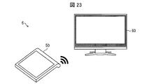
- (A) And (b) is a figure explaining the example in case an employee uses the information processing apparatus as a modification of this invention. It is a figure which shows schematic structure of the information processing apparatus which concerns on Embodiment 6 of this invention.
- Embodiment 1 Hereinafter, embodiments of the present invention will be described with reference to FIGS. 1 to 8 as follows.
- FIG. 1 is a block diagram illustrating an example of a main configuration of the information processing apparatus 1.
- a display device 10 that displays an image and a control device 20 that controls the display device 10 are integrated, and an NFC display 11, a signal information processing unit 12, an NFC communication control unit 13, and a control unit. 21, a storage unit 22, and a display drive unit 23.
- the display device 10 and the control device 20 may be separate. In this case, the display device 10 and the control device 20 transmit and receive information via a communication unit (not shown). Note that transmission / reception of information may be wired or wireless. In addition, the display device 10 and the control device 20 may transmit and receive information via another device such as a router.
- the NFC display 11 is a display having a function of performing short-range wireless communication with an NFC terminal (terminal device).
- the NFC display 11 includes a touch sensor 111, an NFC communication unit 112 (antenna layer), and a display unit 113 (screen).
- NFC refers to general wireless communication with a short reach, and includes short-range wireless communication using RFID (Radio Frequency IDentification) technology such as a non-contact IC (Integrated Circuit) card and a non-contact IC tag.
- RFID Radio Frequency IDentification
- the NFC display 11 can recognize multi-touch such as a 10-point touch, and can operate each work area independently of other work areas in a plurality of work areas described later.
- FIG. 2 is a diagram showing a specific configuration of the NFC display 11.
- the NFC display 11 has a configuration in which each member is superposed in the order of the protective glass 110, the touch sensor 111, the NFC communication unit 112, and the display unit 113 from the outermost part.
- a member in which the touch sensor and the display unit are superimposed is referred to as a “touch panel”.
- the touch sensor 111 is a sensor that detects contact of an object.
- the touch sensor 111 has a detection surface associated with a display unit 113 to be described later, and detects contact of an object with the detection surface.
- FIG. 3A and 3B are diagrams for explaining the principle of the touch sensor 111.
- FIGS. 3C and 3D are diagrams illustrating examples of sensor signals generated when an object comes into contact with the touch sensor 111.
- the touch sensor 111 is formed by vertically superimposing a transparent electrode 115 extending in the Y direction and a transparent electrode 116 extending in the X direction. Then, as shown in FIG. 3B, when a conductive object (finger F in FIG. 3B) contacts the touch sensor 111, the capacitance changes. At this time, by detecting which electrode the capacitance has changed, it is possible to specify the coordinates at which the object is in contact.
- FIG. 3 are diagrams showing examples of sensor signals indicating the amount of change in capacitance when a card having an NFC function as an object is brought into contact with the touch sensor 111.
- a card equipped with the NFC function includes an antenna coil for realizing the NFC function, and the touch sensor 111 can detect contact of the card by the conductivity of the antenna coil.
- a sensor signal as shown in FIG. 3C is generated.
- a sensor signal is generated in the shape of the contact surface of the card (the surface in contact with the touch sensor 111). Specifically, a sensor signal having a shape corresponding to the shape of the antenna coil is generated. If the NFC terminal itself is conductive, a sensor signal having a shape corresponding to the shape of the NFC terminal is generated.
- the touch sensor 111 outputs signal information indicating the sensor signal to the signal information processing unit 12. Specifically, the touch sensor 111 outputs signal information to the signal information processing unit 12 at a frequency of 60 to 240 times per second.
- a capacitive touch sensor is used as the touch sensor 111, but an infrared sensor (light sensor), a pressure-sensitive sensor, or the like may be used as the touch sensor 111.
- the touch sensor 111 may use, as signal information, information on a change in capacitance caused by a hover touch in a state in which the touch sensor 111 is not directly touching, that is, in proximity.
- the touch sensor according to one embodiment of the present invention only needs to have a function of detecting contact or proximity of an object.
- the NFC communication unit 112 is a communication device for performing near field communication with the outside.
- the NFC communication unit 112 is an antenna module (multi-antenna) including a plurality of NFC antennas 114 (antennas).
- the NFC antenna 114 is a transparent antenna having a function as a tag reader that detects an NFC tag and transmits and receives information.
- the NFC communication unit 112 is a sheet-like member provided between the touch sensor 111 and the display unit 113, as shown in FIG.
- three NFC antennas 114 are arranged throughout the NFC communication unit 112 in the vertical direction (the short side direction of the NFC communication unit 112) and four in the horizontal direction (the long side direction of the NFC communication unit 112). Yes.
- the number and layout of the NFC antennas 114 are not limited to the example shown in FIG.
- four NFC antennas 114 may be arranged vertically and five horizontally, as described later, and may be provided only at the four corners of the NFC communication unit 112, or the end of the NFC communication unit 112. It may be provided only in the part.
- the position of the NFC communication unit 112 is not limited to between the touch sensor 111 and the display unit 113 shown in FIG. Further, the NFC antenna 114 may be provided in the touch sensor 111. That is, the touch sensor 111 and the NFC communication unit 112 may be integrated.
- a unique antenna ID for identifying each NFC antenna 114 is assigned in advance to each of the plurality of NFC antennas 114.
- the NFC communication unit 112 can partially drive a plurality of NFC antennas 114 in accordance with an application to be activated (hereinafter also referred to as “application”). Further, the NFC communication unit 112 can arbitrarily select and drive the NFC antenna 114 at a position that is easy for the user to use in accordance with the screen display (layout) of the application. This is one merit of providing a multi-antenna in the NFC communication unit 112.
- the display unit 113 is a display device having an image display function for displaying information processed by the information processing apparatus 1 as an image in a display area.
- the display unit 113 is, for example, an LCD (Liquid Crystal Display, liquid crystal display), but is not limited to this example.
- the display unit 113 may include a backlight.
- the signal information processing unit 12 analyzes the touch signal input to the touch sensor 111 and transmits the touch information to the control unit 21 described later.
- the touch information will be described in detail in the second embodiment. However, in the present embodiment, analysis is not performed as to whether the object that has touched the touch sensor 111 is an NFC terminal or an indicator such as a finger.
- the NFC communication control unit 13 (communication control unit, NFC controller) performs drive control of the NFC antenna 114 based on a control signal from the control unit 21. Further, the NFC communication control unit 13 transmits, to the control unit 21, NFC communication information that is a combination of the terminal information acquired from the NFC terminal and the antenna ID of the NFC antenna 114 with which communication was performed when the terminal information was acquired. .
- Control device 20 Control unit 21
- the control unit 21 controls the respective units of the information processing device 1, particularly the functions of the control device 20.
- the control unit 21 controls the display unit 113 and activates and controls the application in response to a user's touch operation on the NFC display 11.
- the control unit 21 includes a terminal information acquisition unit 211, a position information acquisition unit 212, a work area setting unit 213, an application execution unit 214, and an image generation unit 215.
- the terminal information acquisition unit 211 acquires the terminal information of the NFC terminal via the NFC communication unit 112.
- An example of an NFC terminal is a card with a built-in antenna for NFC communication.
- the terminal information includes an NFC terminal ID that identifies an NFC terminal, terminal data that is unique information held by the NFC terminal, and the like. Further, the terminal information acquisition unit 211 transmits a control signal for acquiring terminal information to the NFC communication control unit 13.
- the position information acquisition unit 212 acquires position information including information on the position of the NFC antenna 114 that has acquired the terminal information, based on the antenna ID included in the NFC communication information. Specifically, the position information acquisition unit 212 inquires the antenna ID of the NFC antenna 114 with which communication was performed when acquiring the terminal information, with the antenna position information stored in the storage unit 22 described later.
- the antenna position information is information indicating a correspondence relationship between the antenna ID of the NFC antenna 114 and the position of the NFC antenna 114 having the antenna ID.
- Information on the position of the NFC antenna 114 is, for example, XY defined on the NFC communication unit 112 with the upper left vertex of the NFC communication unit 112 as the origin when the NFC antenna 114 is rectangular.
- the XY plane coordinates of the upper left and lower right vertices of the NFC antenna 114 in the plane coordinate system may be used.
- XY plane coordinates of the center point of the NFC antenna 114 in the XY plane coordinate system may be used.
- the position information of the NFC antenna 114 is not limited to these examples.
- the work area setting unit 213 sets a plurality of work areas corresponding to each of a plurality of NFC terminals on the NFC display 11, that is, on the display unit 113, based on the position information and the terminal information.
- the work area is an area in which data owned by an individual can be viewed or edited. The setting of the work area by the work area setting unit 213 will be described later. Further, the work area setting unit 213 may instruct the NFC communication unit 112 via the NFC communication control unit 13 to stop driving the NFC antenna 114 superimposed on the work area.
- the application execution unit 214 executes various applications included in the information processing apparatus 1. Specifically, when the user logs in to the information processing apparatus 1, the application execution unit 214 selects an application corresponding to the logged-in user from among the applications stored in the storage unit 22. Run in. Then, the image generation unit 215 is instructed to generate an image. Further, the application execution unit 214 transmits a control signal for driving control of the NFC antenna 114 according to the application and a signal to the NFC terminal by the application to the NFC communication control unit 13.
- the application execution unit 214 controls the application based on the touch information acquired from the signal information processing unit 12. At this time, based on the touch information, the operation instruction is reflected for each work area based on the position information in the work area so that the application can be controlled for each work area.
- Examples of the application executed by the application execution unit 214 include an application that accesses personal data of an in-house server, a cloud, or a personal PC.
- the application execution unit 214 may execute an application that displays on the NFC display 11 a guide indicating the position of the NFC antenna 114 and / or a message that prompts the user to hold the NFC terminal over the NFC antenna 114 as a shared application. Good.
- the image generation unit 215 generates an image in accordance with instructions from the work area setting unit 213 and the application execution unit 214.
- the image generation unit 215 outputs the generated image to the display drive unit 23.
- the display driving unit 23 is a member that controls the display unit 113. Specifically, the display drive unit 23 causes the display unit 113 to display the image acquired from the image generation unit 215.
- control unit 21 includes an authentication unit (not shown) that performs personal authentication based on the NFC terminal ID included in the terminal information.
- authentication unit (not shown) that performs personal authentication based on the NFC terminal ID included in the terminal information.
- the application execution unit 214 accesses personal data authenticated by the authentication unit.
- the storage unit 22 stores various data used by the information processing apparatus 1.
- the storage unit 22 stores at least an application, antenna position information, and a work area pattern.
- the work area pattern is a pattern having a shape and a size corresponding to the terminal information and the position information of the NFC terminal in the work area set when the NFC terminal is held over the NFC antenna 114. Since the application and antenna position information have already been described, they will not be described here.
- login authentication data by the NFC terminal personal setting information, personal data, and the like may be stored in the storage unit 22 and may be stored in an external storage device (not connected) connected to the information processing apparatus 1 via a network. (Shown) may be held.
- the external storage device include a cloud, an in-house server, or a personal PC.
- NFC antenna 114 such as an NFC-equipped mobile terminal, an NFC card, or an NFC terminal such as an NFC tag to perform data transmission / reception, personal authentication, or credit settlement Can be mentioned. Since the NFC antenna 114 is superimposed on the display unit 113, a guide indicating the position of the NFC antenna 114 can be displayed on the display unit 113. For this reason, the user can intuitively operate the NFC display 11.
- an outline of processing (operation) of the information processing apparatus 1 will be described by exemplifying a case where an NFC card for personal authentication is used as an NFC terminal.
- the personal authentication card is, for example, a company employee card or a facility user membership card.
- the NFC terminal may be a mobile terminal such as a smartphone in which information similar to these cards is stored.
- the information processing apparatus 1 is configured to perform personal authentication (login) by holding an NFC card of an employee.
- the terminal information acquisition unit 211 acquires terminal information from the NFC card (terminal information acquisition step), and the NFC terminal ID included in the terminal information is an employee who is permitted to use the information processing apparatus 1. It is determined whether it is the NFC terminal ID.
- the position information acquisition unit 212 stores the ID of the NFC antenna 114 acquired from the NFC communication control unit 13, and the storage The position information of the NFC antenna 114 that communicated when acquiring terminal information is acquired from the antenna position information stored in the unit 22 (position information acquisition step).
- the work area setting unit 213 uses the NFC display based on any one of the position information, the work area information included in the terminal information, and the work area setting pattern stored in the storage unit 22. 11 sets the work area of the employee (work area setting step). Further, by displaying the work area on the display unit 113, the operability of the information processing apparatus 1 by the employee is improved. In particular, in the information processing apparatus 1, the work area can be displayed on the display unit 113 superimposed on the touch sensor 111, so that the operability of the information processing apparatus 1 by employees is further improved.
- the control method of the information processing apparatus 1 can be expressed as follows. That is, the control method of the information processing apparatus 1 for setting the work area acquires the terminal information of each of the plurality of NFC cards held over the NFC communication unit 112 from the terminal device via the NFC communication unit 112.
- a work area setting step of setting a plurality of work areas corresponding to each of the plurality of terminal devices on the display unit 113 based on the position information.
- the work area setting pattern defines the position and size of the work area according to the position information and the use status of the information processing apparatus 1 by other employees.
- the work area information includes information about whether the shape of the work area is vertical or horizontal customized for each employee.
- the “vertical type” means a shape whose vertical length is equal to or greater than the horizontal length
- the “horizontal type” means a shape whose vertical length is shorter than the horizontal length. For the “vertical direction” and “horizontal direction”, see FIG. 4 to be described later.
- the work area information may include the size or aspect ratio of the work area.
- the work area information may be stored in the storage unit 22 in association with the NFC terminal IDs of employees who are permitted to use the information processing apparatus 1.
- the application execution unit 214 executes the application in the work area.
- Examples of the application include an application that displays a personal PC screen set in advance in the work area.
- an application window (application work screen) may be defined in advance for each type of application executed by the application execution unit 214.
- the application is presentation software
- a horizontally long window may be displayed in the work area.
- the application is software for a word processor
- a vertically long window may be displayed in the work area.
- the window size may be defined in advance for each type of application executed by the application execution unit 214.
- the personal PC screen may display personal data on the in-house server or cloud, or may display the screen of the personal PC connected to the in-house LAN by remote access.
- the touch sensor 111 and the display unit 113 are superimposed to constitute a touch panel. For this reason, a touch operation is possible on the screen of the personal PC displayed on the NFC display 11.
- an area other than the work area in use is in a state where another employee can log in.
- the NFC communication control is performed so that the work area setting unit 213 stops driving the NFC antenna 114 superimposed on the work area and drives only the NFC antenna 114 that is not superimposed on the work area.
- the unit 13 may be controlled.
- the application execution unit 214 may execute an application that displays a message prompting another employee to log in in an area other than the work area being used.
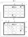
- FIG. 4 is a plan view showing an area division of the NFC display 11.
- the NFC display 11 shown in FIG. 4 has four NFC antennas 114 arranged vertically and five horizontally.
- the NFC display 11 is divided into six regions: upper left, lower left, upper center, lower center, upper right, and lower right.
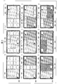
- 5A to 5I are diagrams for explaining the layout of the work area set on the NFC display 11.
- employee card and the work area of the employee A are referred to as an employee card 30A and a work area 40A.
- the work area setting unit 213 reads from the storage unit 22 “when there is an employee card whose position information is the lower left area” and “the work area information of the employee card held over the lower left area is vertical. Read the work area setting pattern (first pattern).
- the work area setting unit 213 sets the entire upper left area and lower left area of the NFC display 11 as the work area 40A of the employee A.
- the upper center, lower center, upper right, and lower right regions are in a state in which NFC communication can be continued, that is, a state in which other employees can log in to the information processing apparatus 1.
- the employee B who has previously set the work area information as the vertical type is arranged in the upper right area of the NFC display 11. Let us consider a case where the user logs in to the information processing apparatus 1 while holding his / her employee card 30B.
- the work area setting unit 213 reads from the storage unit 22 “when there is an employee card whose position information is the lower left area and an employee card whose position information is the upper right area”, “the position information is the lower left area "When the work area information of the employee card is vertical” and "When the work area information of the employee card whose position information is the upper right area is vertical” is the work area setting pattern (second pattern) Is read.
- the work area setting unit 213 sets the entire upper right area and lower right area of the NFC display 11 as the work area 40B of the employee B as shown in FIG. At this time, the upper center and lower center areas on the NFC display 11 are in a state where other employees can log in to the information processing apparatus 1.
- the employee C holds his / her employee card 30C over the NFC antenna 114 disposed in the lower center area of the NFC display 11.
- the work area setting unit 213 reads from the storage unit 22 “an employee card whose position information is the lower left area, an employee card whose position information is the upper right area, and an employee card whose position information is the lower central area. Is present ”,“ when the work area information of the employee card whose position information is the lower left area is vertical ”, and“ the work area information of the employee card whose position information is the upper right area is vertical.
- the work area setting pattern (third pattern) is read out.
- the work area setting unit 213 sets the work area 40A so that the work areas 40A and 40B occupy one third of the NFC display 11 as shown in FIG. And the horizontal width of 40B is reduced. Thereafter, the central area of the NFC display 11 is set as the work area 40C of the employee C. That is, the area on the NFC display 11 is divided into three equal parts in the left-right direction, and the areas are set as the work areas 40A to 40C of the employees A to C.
- the third pattern is defined to give priority to the visibility of the employee C regardless of whether the work area information of the employee C is vertical or horizontal, and the work area 40C is a vertical type.
- the work area setting unit 213 transfers the lower center area of the NFC display 11 and a part of the other area to the work area 40A of the employee A as shown in FIG. Set. At this time, the area not set as the work area 40 ⁇ / b> A on the NFC display 11 is in a state where other employees can log in to the information processing apparatus 1.
- the employee B who has previously set the work area information as the vertical type is arranged in the upper right area of the NFC display 11.
- the work area setting unit 213 reads from the storage unit 22 “when there is an employee card whose position information is the lower center area and an employee card whose position information is the upper right area”, “Work area setting pattern (fifth pattern) when the work area information of the employee card which is the lower area is horizontal type and “when the work area information of the employee card whose position information is the upper right area is vertical type” ).
- the work area setting unit 213 moves the work area 40A to the left as shown in FIG. 5 (e), and moves the upper right area and lower right area of the NFC display 11 to employee B. Is set in the work area 40B.
- the employee C holds his / her employee card 30C over the NFC antenna 114 disposed in the lower center area of the NFC display 11.
- the work area setting unit 213 reads from the storage unit 22 “an employee card whose position information is the lower center area, an employee card whose position information is the upper right area, and an employee card whose position information is the upper left area. Is present ”,“ when the work area information of the employee card whose position information is the lower center area is horizontal ”, and“ the work area information of the employee card whose position information is the upper right area is vertical.
- the work area setting pattern (sixth pattern) is read out.
- the work area setting unit 213 sets the vertical length of the work area 40A to half the vertical length of the NFC display 11, as shown in FIG.
- the area above the work area of employee A is set as work area 40C of employee C.
- the sixth pattern stipulates that the visibility of the employee C is given priority and the work area 40C is a horizontal type regardless of whether the work area information of the employee C is vertical or horizontal.
- the department is set in the work area 40A of the employee A.
- the area not set as the work area 40 ⁇ / b> A on the NFC display 11 is in a state where other employees can log in to the information processing apparatus 1.
- employee B whose work area information is horizontal, has his employee connected to NFC antenna 114 arranged in the lower left area of NFC display 11.
- the work area setting unit 213 reads from the storage unit 22 “when there is an employee card whose position information is the upper right area and an employee card whose position information is the lower left area”, “the position information is the upper right area "When the work area information of the employee card is horizontal” and "when the work area information of the employee card whose position information is the lower left area is horizontal” is read out the work area setting pattern (eighth pattern) .
- the work area setting unit 213 reduces the horizontal length of the work area 40A to half the horizontal length of the NFC display 11, as shown in FIG.
- the lower left area, a part of the lower center area, and the lower right area of the NFC display 11 are set as the work area 40B of the employee B.
- the employee C holds his / her employee card 30C over the NFC antenna 114 disposed in the lower right area of the NFC display 11.
- the work area setting unit 213 reads from the storage unit 22 “an employee card whose position information is the upper right area, an employee card whose position information is the lower left area, and an employee card whose position information is the lower right area. "When the work area information of the employee card whose position information is the upper right area is horizontal” and "When the work area information of the employee card whose position information is the lower left area is horizontal" The work area setting pattern (9th pattern) is read out.
- the work area setting unit 213 sets the vertical length of the work area 40A to half the vertical length of the NFC display 11 as shown in FIG. Then, the area above the work area 40A is set as the work area 40C of the employee C. At this time, the ninth pattern stipulates that the visibility of the employee C is given priority and the work area 40C is horizontal, regardless of whether the work area information of the employee C is vertical or horizontal.
- a part of the upper left area of the NFC display 11 is not included in any of the work areas 40A to 40C. For this reason, the area is in a state where the NFC antenna 114 is driven, and yet another employee can log in.
- the work area setting unit 213 may delete the work areas of the employees. .
- the work area setting unit 213 resets the work areas of the other employees. Also good.
- 6 (a) to 6 (f) are diagrams for explaining the layout of the work area reset on the NFC display 11.
- FIG. Hereinafter, the resetting of the work area when one user logs out from the state where the employees A to C are logged in will be described with reference to FIGS.
- the work area setting unit 213 may reset the work area in the reverse order of the specific example. For example, when the work areas 40A to 40C of the employees A to C who are logged in to the information processing apparatus 1 are set as shown in FIG. Consider a case where an employee C who has logged in lately logs out of the information processing apparatus 1 prior to the employees A and B. In this case, the work area setting unit 213 may delete the work area 40C and reset the work areas 40A and 40B as shown in FIG.
- the work area setting unit 213 reads from the storage unit 22 “when there is an employee card whose position information is the lower left area and an employee card whose position information is the lower central area”, “the position information is the lower left area Work area setting pattern (tenth pattern) when “work area information of employee card is vertical” and “work area information of employee card whose position information is lower center area is vertical” ). At this time, the work area information is not obtained again from the employee card, and the shape of the work area when the work area 40B is deleted is used as the work area information.
- the work area setting unit 213 enlarges the left and right lengths of the work areas 40A and 40C and moves the work area 40C to the right as shown in FIG. 6B. .
- the area overlapped with the NFC antenna 114 located at the right end of the NFC display 11 is not overlapped with the work area, and the work areas 40A and 40C are displayed in other areas. Therefore, the NFC antenna 114 at the right end of the NFC display 11 that does not overlap with the work areas 40A and 40C is driven, and NFC communication is possible.
- the work area setting unit 213 reads from the storage unit 22 “when there is an employee card whose position information is the upper right area and an employee card whose position information is the upper left area”, “the position information is the upper right area "When the work area information of the employee card is horizontal” and "when the work area information of the employee card whose position information is the upper left area is horizontal” is read out the work area setting pattern (11th pattern) .
- the work area setting unit 213 enlarges the work area 40C in the vertical direction as shown in FIG.
- the NFC antenna 114 in the lower left area and the lower center area of the NFC display 11 is not overlapped with the work areas 40B and 40C. Accordingly, some NFC antennas 114 in the lower left area and the lower central area of the NFC display 11 are driven, and NFC communication is possible.
- the work area setting unit 213 reads from the storage unit 22 “when there is an employee card whose position information is the lower left area and an employee card whose position information is the lower right area”, “the position information is lower left Work area setting pattern (the twelfth pattern) of “when the work area information of the employee card as the area is horizontal” and “when the work area information of the employee card whose position information is the lower right area is horizontal” Is read.
- the work area setting unit 213 enlarges the work area 40B in the left-right direction and reduces the work area 40C in the left-right direction, as shown in FIG. Expanding.
- the NFC antenna 114 located at the upper end of the NFC display 11 does not overlap with the work areas 40B and 40C. Therefore, these NFC antennas 114 that do not overlap with the work areas 40B and 40C are driven, and NFC communication is possible.
- the basic size of the work area is based on the size of the NFC antenna 114, the vertical work area is 4 ⁇ 2 antennas, and the horizontal work area is 3 ⁇ 3 antennas. did.
- the basic size is the size of the work area set when there is no possibility of overlapping with another work area.
- the basic sizes of the vertical work area and the horizontal work area are not limited to the above-described example.
- the vertical work area is equivalent to 3 ⁇ 2 antennas
- the horizontal work area is It may be 2 ⁇ 2 antennas or the like.
- the basic size may be another size, and may be set in consideration of the overall size of the display unit 113 and the visibility of the work area.
- the basic size may be adjusted according to the number of NFC antennas 114 included in the information processing apparatus 1.
- the work area has a rectangular shape.
- the shape of the work area may be another shape such as a circular shape or a sector shape along the screen corner.
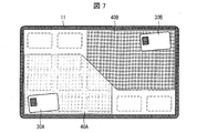
- FIG. 7 is a diagram illustrating an example of another shape of the work area.
- the work area may have a shape (notch shape) lacking in a part of a rectangle in order to avoid overlapping with other work areas, for example, work areas 40A and 40B shown in FIG. Good.
- the work areas 40A to 40C are based on the assumption that the employees A to C are below the NFC display 11 in FIG.
- the work area setting unit 213 recognizes where the employees A to C are on the NFC display according to the orientation of the NFC terminal, and according to the position.
- the work area may be turned upside down or rotated 90 °.
- the setting of the size of the work area may be changed.
- the work area setting unit 213 receives the antenna 2 A vertical work area having a size of x3 may be set. An example of a method for recognizing the orientation of the NFC terminal will be described later.
- the work area setting unit 213 may control the NFC communication control unit 13 to stop driving some of the NFC antennas 114 in accordance with the layout setting state of the work area.
- the application execution unit 214 may execute an application that causes the display unit 113 to display a guide indicating a region where the NFC antenna 114 is driven.
- the work area setting unit 213 sets at least a part of the area on the NFC display 11 as a work area even if the number of users who log in to the information processing apparatus 1 further increases (for example, increases to four or more). It is preferable to leave it open so that other users can log in.
- the work area setting unit 213 displays the NFC display 11 until the number of simultaneously logged-in users reaches the upper limit. It is preferable not to set at least a part of the upper area as a work area. In other words, the work area setting unit 213 provides an area that is not a work area in at least a part of the area on the NFC display 11 until the number of users who are simultaneously using the information processing apparatus 1 reaches the upper limit. It is preferable.
- the work area setting unit 213 may recognize the direction of the NFC terminal held over the NFC antenna 114 and adjust the direction of the work area according to the direction of the NFC terminal. In this case, the direction of the work area can be changed without causing the user to perform a complicated setting operation.
- FIGS. 8A and 8B are diagrams showing examples of NFC terminals that can recognize the orientation held over the NFC antenna 114.
- the conductive pattern 31a is formed at three positions on the back surface of the NFC terminal, that is, the surface facing the NFC display 11.
- the method of arranging is mentioned.
- the touch pattern by the conductive pattern 31a is detected by the touch sensor 111. If the relationship between the positional relationship of the conductive pattern 31a and the direction of the NFC terminal 31 is stored in the storage unit 22 in advance, the vertical direction and angle of the NFC terminal 31 can be recognized based on the touch pattern.
- the conductive patterns 31 a may be arranged at four or more locations on the back surface of the NFC terminal 31.
- the touch sensor built in the NFC display 11 is a capacitive sensor, a touch pattern by an antenna built in the NFC terminal is detected. Therefore, the orientation of the NFC terminal 32 can be recognized by making the shape and arrangement of the built-in antenna 32a and IC chip 32b rotationally asymmetric as in the NFC terminal 32 shown in FIG. 8B.
- rotation symmetry indicates that when a certain figure is rotated, it may coincide with the original figure except when it is rotated by n ⁇ 360 ° (n is a natural number). Further, the shape recognition of the NFC terminal itself by the touch sensor 111 will be described in the second embodiment.
- the information processing apparatus 1 acquires terminal information by communication from the NFC terminal of the user (employee), performs personal authentication, and performs the terminal information and communication when displaying the personal data. Based on the antenna position information, the layout (for example, display position, size, and orientation) of the user's work area is set.
- the work area is automatically set regardless of the user's operation. For this reason, the information processing apparatus 1 is easier to use than the conventional information processing apparatus, and the operability is improved.
- the NFC communication control unit 13 may stop driving the NFC antenna 114 superimposed on the work area. Thereby, the power consumption of the information processing apparatus 1 can be reduced.
- the touch sensor 111 is not an essential component. . This is because touch information, which will be described later, is unnecessary when the work area is set based on the terminal information and the antenna position information. That is, in the information processing apparatus 1, the touch sensor 111 may be excluded from the NFC display 11.
- a known input device such as a mouse or a keyboard is provided to the information processing apparatus 1 in order to cause the user to perform an input operation on the information processing apparatus. What is necessary is just to be provided.
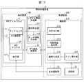
- FIG. 9 is a block diagram illustrating an example of a main configuration of the information processing apparatus 2.
- a display device 10A that displays an image and a control device 20A that controls the display device 10A are integrated.
- the display device 10 ⁇ / b> A includes an NFC display 11 ⁇ / b> A and a signal information processing unit 12 ⁇ / b> A instead of the NFC display 11 and the signal information processing unit 12.
- the control device 20 ⁇ / b> A includes a control unit 21 ⁇ / b> A instead of the control unit 21.
- the NFC display 11A includes an NFC communication unit 112A instead of the NFC communication unit 112.
- the NFC communication unit 112 ⁇ / b> A includes one NFC antenna 114 ⁇ / b> A instead of the plurality of NFC antennas 114. That is, the information processing apparatus 2 of the present embodiment is different from the information processing apparatus 1 of the first embodiment in that it has only one NFC antenna.
- the NFC antenna 114A is an NFC antenna provided only in one corner of the NFC communication unit 112A. In the following description, the position where the NFC antenna 114A is provided is assumed to be the lower right corner of the NFC communication unit 112A.
- the signal information processing unit 12A processes the touch signal acquired from the touch sensor 111.
- the signal information processing unit 12A includes an object determination unit 121 and a touch information generation unit 122.
- the object determination unit 121 determines whether the object in contact with the touch sensor 111 is an indicator such as a finger or a pen, or an NFC terminal (terminal device) having an NFC function. Specifically, the object determination unit 121 determines whether or not the sensor signal indicated by the acquired signal information is a sensor signal generated in a range wider than a predetermined range (that is, the above-described “broad sensor signal”). To do. If the sensor signal is generated in a range wider than the predetermined range, the object is likely to be an NFC terminal. On the other hand, if the sensor signal is generated within a predetermined range or less, the object is likely to be an indicator. The object determination unit 121 outputs the determination result to the touch information generation unit 122.
- a predetermined range that is, the above-described “broad sensor signal”.
- the object determination unit 121 only needs to be able to determine whether the object in contact with the touch sensor 111 is an indicator or an NFC terminal, and the sensor signal indicated by the signal information acquired as described above is within a predetermined range. It is not limited to the configuration for determining whether or not the sensor signal is generated in a wider range. For example, it may be configured to determine whether the number of acquired sensor signals is greater than a predetermined number. In this case, if there is more than the predetermined number, the object is likely to be an NFC terminal. On the other hand, if the number is less than the predetermined number, the object is likely to be an indicator.
- the touch information generation unit 122 generates touch information according to the determination result of the object determination unit 121.
- the touch information generation unit 122 specifies the coordinates (peak coordinates) at which the strongest sensor signal is generated, and the coordinates And the touch ID for identifying the touch information are associated with each other to generate touch information.
- the touch information generation unit 122 performs shape analysis of the sensor signal with reference to the signal information.
- FIG. 10B is a diagram illustrating a specific example of touch information when the object is a rectangular NFC terminal. Note that a virtual XY plane is set in advance in the touch sensor 111 as shown in FIG.
- the touch information generation unit 122 identifies the terminal candidate area from the coordinates where the sensor signal is generated. Subsequently, by correcting the outer edge of the terminal candidate area, the outer peripheral shape (outer shape) of the terminal candidate area is shaped as shown in FIG. Then, the outer peripheral shape shown in FIG. 10A is specified (in the case of FIG.
- the outer peripheral shape is specified as a rectangle), the center coordinates of the rectangle (position information, hereinafter referred to as touch coordinates), size , And the angle of inclination (angle information, hereinafter, angle) is calculated.
- the “angle” is an X axis (first axis) of the XY plane and an axis that is coplanar with the X axis and is an axis (first axis) that is specified based on the outer peripheral shape of the terminal candidate region. The angle formed by the axis 2 and the long side of the rectangle in the example of FIG.
- the touch information generation unit 122 generates the touch information illustrated in FIG. 10B by associating the calculated touch coordinates, the size, the angle, and the shape code indicating the outer peripheral shape of the terminal candidate area with the touch ID. To do.
- the touch information generation unit 122 outputs the generated touch information to an association unit 216 (terminal information acquisition unit, position information acquisition unit, touch position information acquisition unit) described later.
- the shape code is a two-digit number associated with the outer peripheral shape of the terminal candidate area, as shown in FIG. Data in which the outer peripheral shape is associated with the shape code is stored in the storage unit 22 in advance. For example, as illustrated in FIG. 10B, the shape code “01” is associated with the rectangle. Further, as shown in FIG.
- the shape code “03” is associated with an ellipse.
- the association between the shape code and the shape is not limited to this example.
- the shape code “02” may be associated with a circle and “04” may be associated with a triangle.
- the combination (association) of a shape code and a shape, and the number of shape codes are not limited to the example mentioned above.
- the touch ID is made up of information consisting of alphabets and numbers
- the shape code is made up of two digits, which is an example, and the present invention is not limited to this example.
- the size shown in FIG. 10B assumes an NFC terminal having a rectangular outer peripheral shape, H indicates the length of the short side of the NFC terminal, and W indicates the length of the long side of the NFC terminal. Although shown, it is not limited to this example.
- the type of information included in the touch information shown in FIG. 10B is an example, and is not limited to this example.
- “status information” indicating the state of the NFC terminal on the NFC display 11A may be included.
- “status information” indicating the state of the NFC terminal on the NFC display 11A
- “move” indicating that the NFC terminal is moving on the NFC display 11A
- “Touch-out” or the like indicating that the NFC terminal has moved away from the NFC display 11A can be cited, but the present invention is not limited to this example.
- FIG. 11 is a figure which shows an example of each parameter of the terminal candidate area
- FIG. 11B is a diagram illustrating a specific example of touch information when the object is an elliptical NFC terminal.
- a case where the NFC terminal is elliptical will be described.
- omitted is abbreviate.
- the touch information generation unit 122 identifies the shape as an ellipse. Then, as shown in FIG. 11B, the shape code of the touch information is set to “03”.
- H indicates the length of the short diameter of the NFC terminal
- W indicates the length of the long diameter of the NFC terminal. Is shown.
- the “angle” in the example of FIG. 11 is an X axis (first axis) of the XY plane and an axis that is coplanar with the X axis, and is specified based on the outer peripheral shape of the terminal candidate region. Is an angle formed by an axis (second axis, which is an elliptical long diameter in the example of FIG. 11).
- the touch sensor 111 continuously outputs the signal information to the signal information processing unit 12A when the contact of the object continues.
- the touch information generation unit 122 continuously generates touch information based on the acquired signal information, and outputs it to the association unit 216 described later. At this time, the touch information generation unit 122 attaches the same touch ID to the generated touch information until output of the signal information from the touch sensor 111 is interrupted.
- the touch information generation unit 122 executes the above-described processing to generate touch information illustrated in (b) of FIG. 10 and (b) of FIG. Thereafter, when the NFC terminal moves while being in contact with the touch sensor 111, the touch information generation unit 122 continuously generates touch information according to the acquired signal information. At this time, since the NFC terminal is moving, the touch coordinates included in the touch information change.
- the touch information generation unit 122 when the NFC terminal moves while touching the touch sensor 111, the touch information generation unit 122 generates the touch ID of the newly generated touch information, and the touch information generated when the NFC terminal contacts the touch sensor 111. Touch ID. Then, the touch information generation unit 122 outputs the generated touch information to the association unit 216 described later.
- Control device 20A (Control unit 21A)
- the control unit 21A includes an association unit 216 instead of the terminal information acquisition unit 211 and the position information acquisition unit 212.
- the association unit 216 stores the touch information acquired from the signal information processing unit 12A and the NFC terminal information acquired from the NFC communication control unit 13 in association with each other. Specifically, when the association unit 216 acquires touch information from the signal information processing unit 12A, the association information is touch information indicating contact of the indicator or touch information indicating contact of the NFC terminal. Determine whether. More specifically, it is determined whether or not the touch information includes a size, an angle, and a shape code that are unique information in the touch information indicating the contact of the NFC terminal. The specific information is not limited to the above example.
- the associating unit 216 displays the contact indicated by the touch information as the indicator.
- the following processing is performed as contact (finger touch). Specifically, the associating unit 216 outputs the touch information to the application executing unit 214.
- the associating unit 216 acquires the NFC terminal information from the NFC communication control unit 13. To check.
- association data is generated by associating the acquired touch information with the NFC terminal information, and stored in the storage unit 22.
- the association data is obtained by adding NFC terminal information to the touch information described with reference to FIGS. 10B and 11B.
- the association unit 216 stores the association data generated by adding the NFC terminal information to the touch information in the storage unit 22.
- the associating unit 216 confirms the touch ID included in the acquired touch information, and the touch data out of the associating data stored in the storage unit 22. It is confirmed whether there is association data including an ID. When there is such correspondence data, the touch information portion included in the association data is updated to the content of the acquired touch information. As a result, the NFC terminal information generated when the NFC terminal and the information processing apparatus 2 execute NFC communication and the touch information after the NFC terminal moves are stored in association with each other. . Therefore, the information processing apparatus 2 can hold information indicating the latest position of the NFC terminal on the NFC display 11A.
- FIG. 12 is a flowchart illustrating an example of a flow of processing executed by the information processing apparatus 2.
- the signal information processing unit 12A waits for signal information output from the touch sensor 111 (S1).
- the object determination unit 121 specifies the generation range of the sensor signal using the signal information (S2), and determines whether the range is wider than the predetermined range (S2). S3). Then, the determination result is output to the touch information generation unit 122.
- the touch information generation unit 122 determines that the generation source of the sensor signal is a finger, and specifies the peak coordinates in the sensor signal (S6).
- the touch information generation unit 122 determines that the generation source of the sensor signal is an NFC terminal. In this case, the touch information generation unit 122 identifies the terminal candidate area and shapes the outer peripheral shape of the area (S4). Further, the touch information generation unit 122 calculates the touch coordinates, size, and angle in the rectangle (S5).
- the touch information generating unit 122 generates touch information (S7), and outputs the generated touch information to the associating unit 216 (S8). Subsequently, the associating unit 216 executes an associating process (S9). Details of the association process will be described later. When the association process ends, the process returns to step S1.
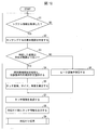
- FIG. 13 is a flowchart illustrating an example of the flow of the association process included in the flowchart of FIG.
- the associating unit 216 is in a state of waiting for touch information (S11, position information acquisition step).
- the associating unit 216 determines whether or not the acquired touch information is touch information indicating contact of the NFC terminal (S12). Specifically, whether the touch information is the touch information shown in (b) of FIG. 10, that is, the touch information includes information unique to the touch information indicating the contact of the NFC terminal, such as size, angle, and shape. Determine if a code is included.
- the associating unit 216 processes the touch indicated by the touch information as a finger touch (S15), and the associating process ends.
- the associating unit 216 confirms whether or not the NFC terminal information has been acquired (S13, terminal information acquisition step).
- the associating unit 216 associates the touch information with the NFC information and stores them in the storage unit 22 (S14, associating step), and the associating process ends. .
- the associating unit 216 confirms whether there is association data including the same touch ID as the acquired touch information (S16). ), When there is association data (YES in S16), the association unit 216 updates the touch information portion of the association data stored in the storage unit 22 (S17). On the other hand, when there is no association data (NO in S16), the association unit 216 deletes the acquired touch information (S18). This completes the association process.
- the associating unit 216 determines that the touch coordinates included in the touch information are those of the NFC antenna 114A. It may be configured to determine whether or not the coordinates correspond to the position.
- FIGS. 14A to 14C are diagrams for explaining the layout of the work area when the first employee logs in to the information processing apparatus 2.
- FIGS. 15A to 15C are diagrams for explaining the layout of the work area when the second employee logs in to the information processing apparatus 2.
- FIGS. 16A to 16C are diagrams for explaining the layout of the work area when the third employee logs in to the information processing apparatus 2.
- the information processing apparatus 2 includes only one NFC antenna 114A at the corner of the NFC display 11A.
- a guide and a message (“log in by touching an employee card”) indicating the position of the NFC antenna 114A and holding the NFC terminal over the application as a shared PC executed by the application execution unit 214 are displayed on the display unit 113. Is displayed.
- the information processing apparatus 2 is a shared PC terminal that can be used by a plurality of employees, as in the specific example of the information processing apparatus 1.
- the NFC terminal is an employee card.
- the position of the NFC antenna 114A is the lower right of the NFC display 11A.
- the work area setting unit reads from the storage unit 22 “when there is an employee card whose position information includes the position of the NFC antenna 114A” and “an employee who is held over the position of the NFC antenna 114A”
- the work area setting pattern (thirteenth pattern) for “when the work area information of the card is horizontal” is read.
- the work area setting unit 213 sets the work area 40A of the employee A near the NFC antenna 114A as shown in FIG. 14 (b).
- “position information” in the work area setting pattern may be indicated by six areas as in the first embodiment, or may be indicated by further subdivided areas.
- the work area setting unit 213 causes the work area corresponding to the shape and position of the employee card 30A to be detected by the touch sensor 111.
- the setting pattern is read from the storage unit 22.
- the work area setting unit 213 resets the layout of the work area 40A. At this time, apparently, the work area 40A moves with the movement of the employee card 30A.
- the application as a shared PC is placed at the position of the NFC antenna 114A. Display the guide again and allow other users to log in. Note that the application as the shared PC may stop driving the NFC antenna 114A while the guide for the NFC antenna 114A is not displayed.
- FIGS. 15A to 15C in a state where the employee A has already logged in to the information processing apparatus 2, a second employee (employee B) has entered the information processing apparatus 2. The case of logging in will be described.
- FIG. 15A illustrates a case where employee B holds his / her employee card 30B over the guide position and logs in to the information processing apparatus 2 is considered.
- FIG. 15A illustrates a case where the layout of the work area 40A is the same as that of FIG. 14C.
- the work area setting unit 213 reads the 13th pattern from the storage unit 22 in the same manner as when the employee A logs in to the information processing apparatus 2. Then, according to the thirteenth pattern, the work area setting unit 213 displays the work area 40B of the employee B near the NFC antenna 114A as shown in FIG.
- the work area setting unit 213 adjusts the position and size of the work area 40B so as not to overlap with the work area 40A.
- the work area setting unit 213 may also adjust the position and size of the work area 40A within a range that does not greatly deviate from the position of the employee card 30A.
- the work area setting unit 213 detects the shape and position of the employee card 30B detected by the touch sensor 111, and the employee card. A work area setting pattern corresponding to the shape and position of 30A is read from the storage unit 22. Then, according to the work area setting pattern, the work area setting unit 213 resets the layouts of the work areas 40A and 40B.
- the work area setting pattern is defined such that the work area 40B does not protrude beyond the display area of the display unit 113.
- the work area setting pattern is the upper right of the display unit 113 for the work area 40B. It is defined as the starting point. If the NFC antenna 114A does not overlap with the work area 40B due to the movement of the employee card 30B, the application as a shared PC displays a guide again at the position of the NFC antenna 114A, and other users log in Is possible.
- FIG. 16A illustrates the case where an employee C holds his / her employee card 30C over the NFC antenna 114A and logs into the information processing apparatus 2.
- FIG. 16A illustrates the case where the layout of the work areas 40A and 40B is the same as that of FIG. 15C.
- the work area setting unit 213 reads the thirteenth pattern in the same manner as when the employees A and B log in to the information processing apparatus 2. Then, according to the thirteenth pattern, the work area setting unit 213 sets the work area 40C of the employee C near the NFC antenna 114A, as shown in FIG.
- the work area setting unit 213 adjusts the position and size of the work area 40C so as not to overlap with the work areas 40A and 40B.
- the work area setting unit 213 may also adjust the positions and sizes of the work areas 40A and 40B within a range that does not greatly deviate from the position of the employee card 30A or 30B.
- the employee A moves the employee card 30A to the lower left corner of the NFC display 11A and rotates it 90 degrees clockwise.
- the work area setting unit 213 resets the position of the work area 40A to the left side of the NFC display 11A, and resets the direction of the work area 40A to be in the horizontal direction when viewed from the left side of the NFC display 11A. .
- an empty area that is not set as the work areas 40A and 40B is created in the center of the NFC display 11A.
- the employee C moves the employee card 30C to the left from the position of the NFC antenna 114A, so that the work area setting unit 213 has a work area setting pattern corresponding to the position information of each of the employee cards 30A to 30C. Accordingly, the work area 40C was reset. As a result, the work area 40C is reset to the empty area at the center of the NFC display 11A.
- the work area setting unit 213 includes angle information included in the touch information (see FIGS. 10B and 11B).
- the direction of the work area 40 ⁇ / b> A may be reset according to the change of.
- an employee card is obtained from a conductive pattern provided on the back side of the employee card 30A or an antenna shape built in the employee card 30A.
- the rotation amount of 30A may be detected.
- the work area setting unit 213 resets the direction of the work area 40A in accordance with the rotation amount of the employee card 30A.
- the work area setting unit 213 When the employee C moves the employee card 30C to the left from the position of the NFC antenna 114A, the work area setting unit 213 generates a work area setting pattern according to the positions of the employee cards 30A to 30C from the storage unit 22. read out. Then, according to the work area setting pattern, the work area setting unit 213 sets the work area 40C in the empty area at the center of the NFC display 11A by adjusting the size and the aspect ratio. At this time, the work area setting unit 213 may adjust the sizes of the work areas 40A and 40B so as to balance the work area 40C.
- touch information of the employee card and terminal information Must be stored in the information processing apparatus 2 in a state of being associated with each other.
- the information processing apparatus 2 uses the association unit 216 to generate and update the association data so that the employee card can be moved in a state where work areas corresponding to two or more employee cards are set. Along with this, it is possible to reset the work area.
- the work area setting unit 213 may control the size of the work area based on the size information included in the touch information of the NFC terminal, that is, the size of the NFC terminal. For example, when the size of the NFC terminal is large, it may be possible to set the size of the work area larger than when the size of the NFC terminal is small.
- the work area setting unit 213 may control the shape of the work area based on the shape code information included in the touch information of the NFC terminal, that is, the shape of the NFC terminal. For example, when the shape of the NFC terminal is an ellipse, the shape of the work area may be an ellipse.
- the information processing apparatus 2 includes the NFC communication unit 112 having a single NFC antenna 114A (single antenna) and also has a function of detecting the shape and position of the NFC terminal by the touch sensor 111 using the touch sensor 111. Have.
- the touch sensor 111 detects the shape and position of the NFC terminal, and stores them in association with the terminal information of the NFC terminal. For this reason, even when a plurality of NFC terminals are held over the NFC display, the position of each NFC terminal can be recognized. Further, when the NFC terminal is held over a position away from the NFC antenna 114A, a guide indicating the position of the NFC antenna 114A can be displayed on the display unit 113.
- the information processing apparatus 2 can always recognize where the NFC terminal that acquired the terminal information has moved, and can change the display position of the work area according to the position. Furthermore, the aspect ratio of the work area can be changed or rotated according to the orientation of the terminal.
- the user's personal authentication is performed using the terminal data acquired from the NFC terminal, and the work area of the user is set. After that, by moving the NFC terminal, the work area is reset to an arbitrary location, and the work area layout (size, orientation, etc.) is automatically adjusted. Therefore, when a plurality of users use the information processing apparatus 2 at the same time, each user can set the work area without needing troublesome setting changes simply by moving and rotating the NFC terminal.
- FIG. 17 is a block diagram illustrating an example of a main configuration of the information processing apparatus 3.
- a display device 10B that displays an image and a control device 20A that controls the display device 10B are integrated.
- the display device 10B includes an NFC display 11, a signal information processing unit 12A, and an NFC communication control unit 13.
- the information processing apparatus 3 of the present embodiment holds the position information of the NFC antenna 114 over which the NFC terminal is held, the terminal information of the NFC terminal, and another NFC terminal. Based on the positional information of the NFC antenna 114, the work area is displayed.
- the information processing apparatus 3 similar to the information processing apparatus 2 according to the second embodiment, detects the post-movement detected by the touch sensor 111 when the user moves the NFC terminal on the NFC display 11.
- the work area is reset based on the position information and angle information of the NFC terminal and the position information and angle information of other NFC terminals.
- FIG. 18 is a figure for demonstrating the point which can improve the information processing apparatus 1 of Embodiment 1.
- FIG. 18B and 18C are diagrams for explaining points that can be improved in the information processing apparatus 2 described in the second embodiment.
- the plurality of NFC antennas 114 are not necessarily arranged in the entire NFC display 11 without a gap.
- the plurality of NFC antennas 114 there is a possibility that an area where NFC communication is impossible, that is, a dead zone area may exist.
- an appropriate position for holding the employee card 30A is set. It is possible to show.
- the employee A holds the employee card 30 ⁇ / b> A over the NFC display 11, the employee A returns to the logged-out state (the state before the login of the employee A).
- the touch may be interrupted at the point X during the movement.
- causes of the interruption include (i) touching the NFC display 11A with a finger while the employee card 30A is moving, or (ii) floating the employee card 30A from the NFC display 11A. Conceivable.
- the employee A since the association between the touch information and the terminal information is also interrupted, the employee A is logged out even though the employee A holds the employee card 30A over the NFC display 11A (employee It will return to the state before member A's login). For this reason, the employee A needs to log in the information processing apparatus 2 again by holding the employee card 30 ⁇ / b> A again at the position of the NFC antenna 114.
- the information processing apparatus 3 can further improve user convenience as compared with the information processing apparatuses 1 and 2 by combining the configurations of the information processing apparatus 1 and the information processing apparatus 2.
- the information processing apparatus 3 of the present embodiment includes a plurality of NFC antennas 114 and stores the touch information and the terminal information in association with each other. Therefore, the information processing apparatus 3 can store the touch information and the terminal information in association with each other in the dead zone between the NFC antennas 114. Thereby, even if the employee card 30A enters the dead zone area, the login state of the employee A is maintained.
- the terminal information is periodically re-read by the plurality of NFC antennas 114 provided. Thereby, even if the touch information is interrupted, the terminal information is updated immediately, so that logout unintended by the employee A can be prevented.
- FIG. 19 are diagrams for explaining an example in which the employees A and B use the information processing apparatus 3.
- a guide indicating the position of the antenna 114 (a frame surrounding the NFC antenna 114) and a message prompting the user to log in ("log in by touching an employee card") are displayed.
- log in a message prompting the user to log in
- employees A and B each log in to the information processing apparatus 3 while holding their own employee card 30A or 30B at the position where the guide is displayed.
- the information processing apparatus detects the position where the employee card is held by the touch sensor 111.
- a guide indicating the position of the NFC antenna 114 closest to the held position may be displayed on the NFC display 11.
- the work area corresponding to the employee cards 30 ⁇ / b> A and 30 ⁇ / b> B is displayed on the NFC display 11 after login. Thereafter, as shown in FIG. 19 (b), when the employee cards 30A and 30B are moved, the corresponding work area is also moved.
- the touch information of the employee card and the terminal information of the employee card can be associated with each other as in the information processing apparatus 2 of the second embodiment. For this reason, when the employee card is moved after logging in, even if communication is interrupted when passing through the dead zone, the employee does not log out.
- the information processing apparatus 3 includes a plurality of NFC antennas 114 as in the information processing apparatus 1 of the first embodiment.
- the employee card passes through the area where it can communicate with the NFC antenna 114, communication is performed each time, and the terminal information associated with the touch information is updated.
- the employee card 30A communicates with a plurality of NFC antennas 114a that pass upward during the movement.
- the employee card 30B communicates with a plurality of NFC antennas 114b that pass upward during the movement.
- the new terminal information can be associated with the touch information if it passes over the NFC antenna. . For this reason, even if said interruption occurs, the state where the employee logged in to the information processing apparatus 3 is maintained.
- the terminal information and the touch information are If there is an error in the association, the touch information is associated with the terminal information again, and login authentication is performed again.
- the information processing apparatus 3 includes a plurality of NFC antennas 114, and can store terminal information and touch information in association with each other. For this reason, the log-in state is maintained even in the dead zone area on the NFC display 11, and unintended logout due to the interruption of touch is suppressed.
- the information processing apparatus 4 has a function of adjusting the layout of the application window displayed in the work area on the information processing apparatus 2 according to the second embodiment (that is, the information processing apparatus having one NFC antenna). It may be understood that this is an addition. Note that the layout method of the work area in the present embodiment is the same as that in the second embodiment, and a description thereof will be omitted.
- a menu for starting the application is displayed on the user, and a new work area is displayed after the application starts. It may be set.
- FIG. 20 are diagrams for explaining an example in which an employee uses the information processing apparatus 4.
- a menu MA and window WA described later are in the work area (not shown) of the employee A
- a menu MB and window WB described later are in the work area (not shown) of the employee B. Respectively).
- the employee A holds his / her employee card 30A over the NFC antenna 114A and logs in to the information processing apparatus 4.
- the display driving unit 23 displays the menu MA for the employee A on the NFC display 11A.
- Menu MA is a window in which icons for starting various applications that can be used by employee A are displayed side by side. That is, the menu MA is an image in which icons to be input by a user for starting an application are arranged. The menu MA is displayed in the vicinity of the employee card 30A.
- the display driving unit 23 detects the employee card detected by the touch sensor 111.
- the position of the menu MA is changed according to the position of 30A.
- the menu MA moves following the movement of the employee card 30A.
- the display driving unit 23 controls the display of the menu MA according to the position of the employee card 30A so that icons displayed in the menu MA do not overlap with the employee card 30A.
- the menu MA is displayed in the lower right direction with respect to the employee card 30A.
- An icon is arranged in the menu MA.
- the employee card 30A is located in the lower right area of the NFC display 11A (in the case of FIG. 20A)
- the menu MA is displayed in the upper left direction with respect to the employee card 30A.
- An icon is arranged in the menu MA.
- FIG. 20C illustrates a case where the employee A touches the icon IA and tries to activate an application corresponding to the icon IA.
- the window WA of the application corresponding to the icon IA is displayed by the display driving unit 23.
- the layout of the menu MA may be reset with the display of the window WA. This also applies to the menu MB described below.
- the layout of the application window may be specified in advance for each type of application.
- the layout of the window WA is defined in advance so that the window WA is displayed as being vertically long.
- a vertically long layout may be specified in advance.
- a horizontally long layout may be defined in advance.
- the window layout may be defined in advance so that the window size is relatively small. Note that the ratio of the size of the window or the length and width may be appropriately changed by a user operation.
- FIG. 20 (e) employee B holds his / her employee card 30B over NFC antenna 114A and logs into information processing apparatus 4. Thereby, the menu MB for the employee B is displayed.
- FIG. 20E illustrates a case where employee B touches icon IB and tries to activate an application corresponding to icon IB.
- an application window WB corresponding to the icon IB is displayed.
- the menu MB and the window WB are displayed in the work area of the employee B, the menu MA and the window WA displayed in the work area of the employee A do not overlap. That is, the menu MB and the window WB can be displayed while avoiding the menu MA and the window WA for the employee A.
- the number of applications that each user (employee) starts is not limited to only one.
- Each user can activate a plurality of applications and display windows corresponding to the applications side by side in his / her work area.
- the information processing apparatus 4 of the present embodiment it is possible to adjust the layout of the window of the application displayed in the work area of each user. Therefore, even when a plurality of users log in to the information processing apparatus 4 at the same time, the screen of the NFC display 11A can be used efficiently by each user. For this reason, it becomes possible to implement
- the work area setting unit may set a menu (for example, menu MA) displayed on the NFC display as the work area when the employee A logs in.
- This menu may be understood as a work area in an initial state (at the time of login). Accordingly, the menu can be handled as a work area, and a work area corresponding to the menu can be set.
- the work area setting unit 213 newly creates a work area (for example, a window WS) according to an application activated by a user input operation with respect to an icon in the menu (for example, according to the type of the application). May be set to In this case, for example, the menu MA and the window WS are the work areas of the employee A. Thereby, the work area according to the activation of the application can be set.
- a work area for example, a window WS
- an application activated by a user input operation with respect to an icon in the menu for example, according to the type of the application.
- the information processing apparatus 5 of the present embodiment is an application displayed in the work area on the information processing apparatus 1 of the first embodiment or the information processing apparatus 3 of the third embodiment (that is, an information processing apparatus having a plurality of NFC antennas). It may be understood that the function of adjusting the layout of the window is added. Note that the layout method of the work area in the present embodiment is the same as that in the first or third embodiment, and a description thereof will be omitted. In the information processing apparatus 5, the process of detecting the position of the employee card by the touch sensor 111 (the process of acquiring touch information) is not essential.
- FIG. 21 are diagrams for explaining an example in which an employee uses the information processing apparatus 4.
- the menu MA and the window WA are in the work area (not shown) of the employee A
- the menu MB and the window WB are in the work area (not shown) of the employee B.
- Menu MC and window WC which will be described later, are displayed in the work area (not shown) of employee B, respectively.
- each of the employees A and B holds his / her employee cards 30A and 30B over the NFC antenna 114 and logs into the information processing apparatus 4.
- the employee A holds the employee card 30A over the NFC antenna 114 located at the lower left of the NFC display 11.
- the employee B holds the employee card 30 ⁇ / b> B over the NFC antenna 114 located at the upper right of the NFC display 11.
- each of the menus MA and MB is displayed on the NFC display 11 by the display driving unit 23.
- the display positions of the menus MA and MB are set based on the position information described above.
- employees A and B touch icons IA and IB, respectively, to activate a desired application.
- FIG. 21B an area (an area not set as a work area) where an additional user can log in is left in the lower left of the NFC display 11. This area may be referred to as a margin area.
- the work area setting unit 213 determines whether or not to allow additional user login in the margin area according to the number of windows displayed on the NFC display 11 or the type of application corresponding to the window. (Determination) may be performed. Note that the number of windows and types of applications used for the determination may be defined in advance.
- the work area setting unit 213 may add an additional user in the margin area. Allow login of.
- the work area setting unit 213 displays an additional user in the margin area. Do not allow login. Thereby, the visibility and operability of each user can be maintained.
- FIG. 21C illustrates a case where login of an additional user in the margin area is permitted.
- the employee C (additional user) holds his / her employee card 30C over the NFC antenna 114 (not shown) in the margin area and logs into the information processing apparatus 4.
- the menu MC for the employee C is further displayed on the NFC display 11.
- the employee C touches the icon IC displayed in the menu MC in order to activate a desired application.
- an application window WC corresponding to the icon IC touched by the employee C is displayed. Since menu MC and window WC are displayed in the work area of employee C, (i) menu MA and window WA displayed in the work area of employee A, and (ii) employee B The menu MB and the window WB displayed in the work area do not overlap.
- the information processing apparatus 5 of the present embodiment it is possible to adjust the layout of the window of the application displayed in the work area of each user, as in the above-described fourth embodiment. Note that the information processing apparatus 5 according to the present embodiment can not permit additional users to log in in the margin area, which is particularly useful when the work area of each user is small.
- one screen may be shared by a plurality of users.
- the user holds the card and logs in to the information processing apparatus, it can be recorded as a history that the user has participated in the TV conference.
- it is possible to notify the other party of the TV conference that the user has participated in the TV conference.
- FIG. 22 are diagrams for explaining an example in which an employee uses the information processing apparatus 4x.
- the information processing device 4x is illustrated as a modification of the information processing device of the fourth embodiment.
- the function of this modification may be added to the information processing apparatus 5 of the fifth embodiment.
- a function of moving data between the window WA and the window WB may be added to the information processing apparatus, for example, by drag and drop. This makes it easy to exchange and share data between users.
- a shared folder WS shared work area
- the work area setting unit 213 includes a plurality of work areas (windows WA and WB) corresponding to a plurality of users (users A and B).
- a shared folder that accepts an input operation by each of the users may be set.
- Users A and B can move data to this common folder WS, for example, by drag and drop.
- the provision of the shared folder WS also facilitates the exchange of data or sharing among the users.
- the configuration of FIG. 22B is useful.
- the process at the time of logout in the information processing apparatus is not limited to this.
- the image displayed in the user's work area is displayed within a predetermined time (for example, 10 seconds). It may be held without being erased.
- the work area setting unit 213 is separated from the NFC display (more specifically, the NFC communication unit arranged on the NFC display). After a predetermined time, the setting of the work area corresponding to the employee card may be canceled and the image displayed in the work area may be deleted.
- the user can browse or edit data using the held image (window or the like) by holding the employee card over the NFC display within a predetermined time and logging in again.
- the information processing apparatus may notify the user to hold the employee card again on the NFC display and perform the operation thereafter.
- FIG. 23 is a diagram illustrating a schematic configuration of the information processing apparatus 6.
- the information processing device 6 is configured by combining a touch pad 50 and a display device 60.
- a touch sensor for detecting contact or proximity of an object and a display unit (display device 60) having an image display function are provided separately.
- the information processing apparatus 6 of the present embodiment is different from the information processing apparatuses of the above-described embodiments in this respect.
- the antenna is arranged so as to be superimposed on the touch pad 50.
- the touch pad 50 is configured to be able to communicate with the display device 60, and transmits touch information and terminal information to the display device 60.
- the communication method between the touch pad 50 and the display device 60 may be wireless as shown in FIG. 23 or wired. Accordingly, the display device 60 displays an image reflecting the touch information and the NFC terminal information, for example, a work area of the user holding the NFC terminal over the touch pad 50, a pointer indicating the touch position of the user in the work area, and the like. .
- the touch pad 50 and the display device 60 that are provided separately are used instead of the NFC display 11 in which the touch sensor and the display unit are integrally provided. It may be realized by combining.
- control blocks (particularly the control units 21 and 21A) of the information processing apparatuses 1 to 6 and 4x may be realized by a logic circuit (hardware) formed in an integrated circuit (IC chip) or the like, or may be a CPU (Central Processing Unit). Unit) and may be realized by software.
- a logic circuit hardware
- IC chip integrated circuit
- CPU Central Processing Unit
- the information processing apparatuses 1 to 4 include a CPU that executes instructions of a program that is software that implements each function, and a ROM (Read Only) in which the program and various data are recorded so as to be readable by a computer (or CPU).
- Memory or a storage device (these are referred to as “recording media”), a RAM (Random Access Memory) for expanding the program, and the like.
- the objective of this invention is achieved when a computer (or CPU) reads the said program from the said recording medium and runs it.
- a “non-temporary tangible medium” such as a tape, a disk, a card, a semiconductor memory, a programmable logic circuit, or the like can be used.
- the program may be supplied to the computer via an arbitrary transmission medium (such as a communication network or a broadcast wave) that can transmit the program.
- an arbitrary transmission medium such as a communication network or a broadcast wave
- one embodiment of the present invention can also be realized in the form of a data signal embedded in a carrier wave, in which the program is embodied by electronic transmission.
- An information processing apparatus (1) according to an aspect 1 of the present invention is arranged so as to overlap with a display device (for example, the display unit 113 or the display device 60) having a screen for displaying a work area, and is short-range wireless.
- a display device for example, the display unit 113 or the display device 60
- a communication unit (NFC communication unit 112) that performs communication, and a terminal information acquisition unit (211) that acquires terminal information of each of the plurality of terminal devices held over the communication unit from the terminal device via the communication unit ),
- a position information acquisition unit (212) that acquires position information including information on the position of the antenna (NFC antenna 114) that acquired the terminal information among a plurality of antennas included in the communication unit, and the terminal information and
- a work area setting unit (213) for setting a plurality of work areas corresponding to each of the plurality of terminal devices on the screen based on the position information;
- the communication unit that is arranged so as to overlap the screen of the display device and includes a plurality of antennas performs short-range wireless communication with the terminal device.
- the terminal information acquisition unit acquires terminal information from the terminal device via the communication unit.
- the position information acquisition unit acquires the position of the antenna from which the terminal information has been acquired as position information.
- the work area setting unit sets a plurality of work areas corresponding to each of the plurality of terminal devices on the screen of the display device based on the terminal information and the position information. Therefore, the size of the work area on the screen can be automatically adjusted.
- An information processing device (3) has a detection surface associated with the screen in aspect 1, and a touch sensor (111) that detects contact or proximity of an object to the detection surface. And a touch position information acquisition unit (association unit 216) that acquires touch information including information on a position at which each of the plurality of terminal devices is in contact with or in proximity to the touch sensor. It is preferably superimposed on the touch sensor, and the work area setting unit preferably sets a plurality of work areas based on the touch information.
- the work area setting unit sets a plurality of work areas based further on the touch information.
- An information processing apparatus (2) is an information processing apparatus that is communicably connected to a display device (for example, the display unit 113 or the display device 60) having a screen that displays a work area, A touch sensor that has a detection surface associated with the screen and detects contact or proximity of an object to the detection surface; and a single antenna (superimposed on the touch sensor) that performs short-range wireless communication (
- the communication unit for example, the NFC communication unit 112A or the NFC communication unit 112 including the NFC antenna 114A or the NFC antenna 114
- terminal information held by each of the plurality of terminal devices held over the communication unit are used for the communication.
- a terminal information acquisition unit (association unit 216) that acquires from the terminal device via a unit, and each of the plurality of terminal devices includes the touch sensor. Based on the touch information and the terminal information, a position information acquisition unit (association unit 216) that acquires touch information including information on a position that is in contact with or in proximity, and a plurality of the terminal devices on the screen.
- a work area setting unit that sets a plurality of work areas corresponding to each of the work areas.
- the communication unit that is arranged to be superimposed on the touch sensor and includes a plurality of antennas performs short-range wireless communication with the terminal device.
- the terminal information acquisition unit acquires terminal information from the terminal device via the communication unit.
- the position information acquisition unit acquires touch information including information on a position where the terminal device is in contact with or close to the touch sensor.
- the work area setting unit sets a plurality of work areas corresponding to each of the plurality of terminal devices on the screen of the display device based on the terminal information and the touch information. Therefore, the size of the work area on the screen can be automatically adjusted.
- the information processing apparatus further includes a display unit (113) having a function as the display apparatus in the above aspect 3.
- the display unit is superimposed on the touch sensor.
- the information processing apparatus is the information processing apparatus according to any one of the aspects 2 to 5, wherein the work area setting unit detects an angle of the terminal device with respect to the touch sensor, and the screen is based on the angle. It is preferable to set the direction of the work area.
- the direction of the work area is set based on the direction of the terminal device, the direction of the work area on the screen can be changed without causing the user to perform a complicated setting operation.
- An information processing apparatus further includes a communication control unit (NFC communication control unit 13) that performs drive control of an antenna included in the communication unit according to any one of the above aspects 1 to 6, and includes the communication control. It is preferable that the unit stops driving the antenna arranged so as to overlap the work area.
- NFC communication control unit 13 NFC communication control unit 13
- the power consumption of the information processing apparatus can be reduced.
- An information processing apparatus is the information processing apparatus according to any one of aspects 1 to 7, wherein an upper limit is set for a number of people who can use the information processing apparatus at the same time, and the work area setting unit It is preferable to provide an area that is not the work area in at least a part of the screen until the number of people who are simultaneously using reaches the upper limit.
- the state in which the user can log in to the information processing device is maintained until the number of people who are simultaneously using the information processing device reaches the upper limit.
- the information processing apparatus is the information processing apparatus according to any one of the aspects 1 to 8, wherein the screen includes a menu (for example, a menu) in which icons to be input by a user for starting an application are arranged. MA) is displayed, and the work area setting unit preferably sets the menu as the work area.
- a menu for example, a menu
- MA the work area setting unit
- the menu can be handled as a work area, a work area corresponding to the menu can be set.
- the information processing apparatus is the information processing apparatus according to any one of the aspects 9, wherein the work area setting unit newly sets the work area according to the application activated by the input operation on the icon. Is preferred.
- a work area can be set according to the activation of the application.
- the information processing apparatus is the information processing apparatus according to any one of the aspects 1 to 10, wherein the work area setting unit includes a plurality of the users between the work areas corresponding to the plurality of users. It is preferable to set a shared work area (shared folder WS) for receiving input operations by each of the above.
- the information processing apparatus is the information processing apparatus according to any one of the aspects 1 to 11, wherein the work area setting unit is predetermined after the short-range wireless communication between the communication unit and the terminal device is stopped. After this time, it is preferable to cancel the setting of the work area corresponding to the terminal device and to erase the image displayed in the work area.
- a control device (20) includes an information processing device including a display device having a screen that displays a work area, and a communication unit that is superimposed on the screen and performs near field communication.
- a terminal information acquisition unit that acquires terminal information of each of the plurality of terminal devices held over the communication unit from the terminal device via the communication unit, and a plurality of the communication units A plurality of terminal devices on the screen based on the terminal information and the position information, and a position information acquiring unit that acquires position information including information on the position of the antenna that acquired the terminal information
- a work area setting unit that sets a plurality of work areas corresponding to each of the work areas.
- a control method is a control method for an information processing apparatus including a display device having a screen for displaying a work area, and a communication unit that is arranged so as to overlap the screen and performs short-range wireless communication.
- a work area setting step for setting a plurality of corresponding work areas.
- the information processing apparatus may be realized by a computer.
- the information processing apparatus is operated on each computer by causing the computer to operate as each unit (software element) included in the information processing apparatus.
- the control program for the information processing apparatus to be realized in this way and a computer-readable recording medium on which the control program is recorded also fall within the scope of the present invention.
- NFC communication control unit (communication control unit) 20, 20A Control device 50 Touch pad (touch sensor) 60 Display device (display unit) 111 Touch sensor 112, 112A NFC communication unit (communication unit) 113 Display (screen) 114, 114A NFC antenna (antenna) 211 terminal information acquisition unit 212 position information acquisition unit 213 work area setting unit 216 association unit (terminal information acquisition unit, position information acquisition unit, touch position information acquisition unit) MA, MB, MC Menu WS Shared folder (shared work area)
Abstract
To provide an information processing device capable of automatically adjusting the size and the like of an operation region. An information processing device (1) is provided with: a display device (10) having a screen for displaying an operation region; a near field communication (NFC) unit (112) disposed by being superimposed with the screen; a terminal information acquisition unit (211) that acquires terminal information of a terminal device; a positional information acquisition unit (212) that acquires positional information of a NFC antenna (114) that acquired the terminal information; and an operation region setting unit (213) that sets the operation region.
Description
以下の開示は、近距離無線通信を行う通信部を備える表示装置が端末装置から近距離無線通信によって取得した情報を処理する情報処理装置などに関する。
The following disclosure relates to an information processing apparatus that processes information acquired by a display device including a communication unit that performs short-range wireless communication from a terminal device through short-range wireless communication.
近年、近距離無線通信(Near Field Communication、以下、NFC)用の透明アンテナを内蔵したディスプレイの開発が進められている。当該ディスプレイは、前面に透明アンテナ層を搭載することにより、ディスプレイの表示面に端末装置(NFC端末、例えば、NFC機能搭載スマートフォン、NFC機能搭載カードなど)を近づけることで通信が可能となる。
In recent years, the development of a display incorporating a transparent antenna for near field communication (NFC) has been underway. By mounting a transparent antenna layer on the front surface of the display, communication can be performed by bringing a terminal device (NFC terminal, for example, an NFC function-equipped smartphone, an NFC function-equipped card, or the like) closer to the display surface of the display.
このようなディスプレイを備える情報処理装置について、複数人が同時に使用することを可能とするものとして、例えば特許文献1には、タッチパネルディスプレイと当該タッチパネルディスプレイとは別に設けられた複数のセンサユニットとを備えた卓上情報処理装置が記載されている。上記卓上情報処理装置においては、センサユニットがIDカードの情報を読み取り、各個人の作業領域をタッチパネルディスプレイに表示する。デスクトップ画面を表示する向きは、複数のセンサユニットのうち、いずれのセンサからIDカード情報が取得されたかにより決定される。
Regarding an information processing apparatus including such a display, for example, Patent Document 1 discloses that a touch panel display and a plurality of sensor units provided separately from the touch panel display are provided so that a plurality of people can use them simultaneously. A desktop information processing apparatus provided is described. In the desktop information processing apparatus, the sensor unit reads the information on the ID card and displays each person's work area on the touch panel display. The direction in which the desktop screen is displayed is determined depending on which sensor among the plurality of sensor units has acquired the ID card information.
しかしながら、特許文献1に開示されている卓上型情報処理装置においては、IDカードの情報を読み取った時点で表示される作業領域のサイズは、あらかじめ決定されている。作業領域のサイズ調整については、ユーザがログインするたびに手動で操作する必要があり、手間がかかるという問題があった。
However, in the desktop information processing apparatus disclosed in Patent Document 1, the size of the work area displayed when the information on the ID card is read is determined in advance. Regarding the size adjustment of the work area, it has to be manually operated every time the user logs in, which is troublesome.
そこで、以下の開示においては、作業領域のサイズなどを自動的に調整することが可能な情報処理装置を提供することを目的とする。
Therefore, in the following disclosure, an object is to provide an information processing apparatus capable of automatically adjusting the size of a work area and the like.
上記の課題を解決するために、本発明の一態様に係る情報処理装置は、作業領域を表示する画面を有する表示装置と、上記画面に重畳して配され、近距離無線通信を行う通信部と、上記通信部にかざされた複数の端末装置のそれぞれが有する端末情報を、上記通信部を介して上記端末装置から取得する端末情報取得部と、上記通信部が備える複数のアンテナのうち、上記端末情報を取得したアンテナの位置の情報を含む位置情報を取得する位置情報取得部と、上記端末情報および上記位置情報に基づいて、上記画面上に、複数の上記端末装置のそれぞれに対応する複数の作業領域を設定する作業領域設定部と、を備える。
In order to solve the above problems, an information processing apparatus according to an aspect of the present invention includes a display device having a screen that displays a work area, and a communication unit that is arranged so as to overlap with the screen and performs short-range wireless communication And a terminal information acquisition unit that acquires terminal information of each of the plurality of terminal devices held over the communication unit from the terminal device via the communication unit, and a plurality of antennas included in the communication unit, Corresponding to each of the plurality of terminal devices on the screen based on the terminal information and the position information based on the terminal information and the position information, and a position information acquisition unit that acquires position information including the position information of the antenna that acquired the terminal information A work area setting unit for setting a plurality of work areas.
また、本発明の一態様に係る情報処理装置は、作業領域を表示する画面を有する表示装置と通信可能に接続された情報処理装置であって、上記画面と対応付けられた検出面を有し、当該検出面に対する物体の接触または近接を検出するタッチセンサと、上記タッチセンサに重畳して配され、近距離無線通信を行う、1つのアンテナを備える通信部と、上記通信部にかざされた複数の端末装置のそれぞれが有する端末情報を、上記通信部を介して上記端末装置から取得する端末情報取得部と、複数の上記端末装置のそれぞれが上記タッチセンサに接触または近接している位置の情報を含むタッチ情報を取得する位置情報取得部と、上記タッチ情報および上記端末情報に基づいて、上記画面上に、複数の上記端末装置のそれぞれに対応する複数の作業領域を設定する作業領域設定部と、を備える。
An information processing device according to one embodiment of the present invention is an information processing device communicably connected to a display device having a screen that displays a work area, and includes a detection surface associated with the screen. A touch sensor that detects contact or proximity of an object to the detection surface, a communication unit that is superimposed on the touch sensor and performs short-range wireless communication, and is held over the communication unit A terminal information acquisition unit that acquires terminal information possessed by each of a plurality of terminal devices from the terminal device via the communication unit, and a position at which each of the plurality of terminal devices is in contact with or close to the touch sensor. A position information acquisition unit that acquires touch information including information, and a plurality of terminals corresponding to each of the plurality of terminal devices on the screen based on the touch information and the terminal information. And a work area setting unit for setting a working area.
また、本発明の一態様に係る制御装置は、作業領域を表示する画面を有する表示装置と、上記画面に重畳して配され、近距離無線通信を行う通信部と、を備える情報処理装置の制御装置であって、上記通信部にかざされた複数の端末装置のそれぞれが有する端末情報を、上記通信部を介して上記端末装置から取得する端末情報取得部と、上記通信部が備える複数のアンテナのうち、上記端末情報を取得したアンテナの位置の情報を含む位置情報を取得する位置情報取得部と、上記端末情報および上記位置情報に基づいて、上記画面上に、複数の上記端末装置のそれぞれに対応する複数の作業領域を設定する作業領域設定部と、を備える。
In addition, a control device according to one embodiment of the present invention is an information processing device including: a display device having a screen that displays a work area; and a communication unit that is superimposed on the screen and performs near field communication. A control device, a terminal information acquisition unit that acquires terminal information of each of the plurality of terminal devices held over the communication unit from the terminal device via the communication unit, and a plurality of the communication unit includes Among the antennas, a position information acquisition unit that acquires position information including information on the position of the antenna that acquired the terminal information, and a plurality of the terminal devices on the screen based on the terminal information and the position information. A work area setting unit that sets a plurality of work areas corresponding to each of the work areas.
また、本発明の一態様に係る制御方法は、作業領域を表示する画面を有する表示装置と、上記画面に重畳して配され、近距離無線通信を行う通信部と、を備える情報処理装置の制御方法であって、上記通信部にかざされた複数の端末装置のそれぞれが有する端末情報を、上記通信部を介して上記端末装置から取得する端末情報取得ステップと、上記通信部が備える複数のアンテナのうち、上記端末情報を取得したアンテナの位置の情報を含む位置情報を取得する位置情報取得ステップと、上記端末情報および上記位置情報に基づいて、上記画面上に、複数の上記端末装置のそれぞれに対応する複数の作業領域を設定する作業領域設定ステップと、を含む。
A control method according to an aspect of the present invention is an information processing apparatus including: a display device having a screen that displays a work area; and a communication unit that is superimposed on the screen and performs near field communication. A control method, the terminal information acquisition step of acquiring terminal information possessed by each of the plurality of terminal devices held over the communication unit from the terminal device via the communication unit, and a plurality of the communication unit Among the antennas, a position information acquisition step of acquiring position information including information on the position of the antenna that acquired the terminal information, and a plurality of the terminal devices on the screen based on the terminal information and the position information. A work area setting step for setting a plurality of work areas corresponding to the respective work areas.
本発明の一態様に係る情報処理装置によれば、作業領域のサイズなどを自動的に調整することが可能になるという効果を奏する。
The information processing apparatus according to one aspect of the present invention has an effect that the size of the work area and the like can be automatically adjusted.
また、本発明の一態様に係る制御装置および制御方法によれば、タッチセンサおよび通信部を備える情報処理装置を、タッチセンサ上における作業領域のサイズなどを自動的に調整するように制御することが可能になるという効果を奏する。
Further, according to the control device and the control method according to one aspect of the present invention, the information processing device including the touch sensor and the communication unit is controlled to automatically adjust the size of the work area on the touch sensor. There is an effect that becomes possible.
〔実施形態1〕
以下、本発明の実施の形態について、図1~図8に基づいて説明すれば、以下のとおりである。Embodiment 1
Hereinafter, embodiments of the present invention will be described with reference to FIGS. 1 to 8 as follows.
以下、本発明の実施の形態について、図1~図8に基づいて説明すれば、以下のとおりである。
Hereinafter, embodiments of the present invention will be described with reference to FIGS. 1 to 8 as follows.
(情報処理装置1)
まず、本実施形態に係る情報処理装置1の要部構成について、図1を参照して説明する。図1は、情報処理装置1の要部構成の一例を示すブロック図である。情報処理装置1は、画像を表示する表示装置10と、表示装置10を制御する制御装置20とが一体となっており、NFCディスプレイ11、シグナル情報処理部12、NFC通信制御部13、制御部21、記憶部22、および表示駆動部23を備えている。 (Information processing apparatus 1)
First, a configuration of main parts of theinformation processing apparatus 1 according to the present embodiment will be described with reference to FIG. FIG. 1 is a block diagram illustrating an example of a main configuration of the information processing apparatus 1. In the information processing apparatus 1, a display device 10 that displays an image and a control device 20 that controls the display device 10 are integrated, and an NFC display 11, a signal information processing unit 12, an NFC communication control unit 13, and a control unit. 21, a storage unit 22, and a display drive unit 23.
まず、本実施形態に係る情報処理装置1の要部構成について、図1を参照して説明する。図1は、情報処理装置1の要部構成の一例を示すブロック図である。情報処理装置1は、画像を表示する表示装置10と、表示装置10を制御する制御装置20とが一体となっており、NFCディスプレイ11、シグナル情報処理部12、NFC通信制御部13、制御部21、記憶部22、および表示駆動部23を備えている。 (Information processing apparatus 1)
First, a configuration of main parts of the
なお、情報処理装置1は、表示装置10と制御装置20とが別体であってもよい。この場合、表示装置10と制御装置20とは、通信部(不図示)を介して情報の送受信を行う。なお、情報の送受信は有線によるものであってもよいし、無線によるものであってもよい。また、表示装置10と制御装置20とが、ルータなどの別装置を介して情報の送受信を行ってもよい。
In the information processing device 1, the display device 10 and the control device 20 may be separate. In this case, the display device 10 and the control device 20 transmit and receive information via a communication unit (not shown). Note that transmission / reception of information may be wired or wireless. In addition, the display device 10 and the control device 20 may transmit and receive information via another device such as a router.
(表示装置10)
NFCディスプレイ11は、NFC端末(端末装置)との近距離無線通信を行う機能を備えたディスプレイである。NFCディスプレイ11は、タッチセンサ111、NFC通信部112(アンテナ層)、および表示部113(画面)を備えている。なお、NFCとは、到達距離の短い無線通信全般を示し、例えば非接触IC(Integrated Circuit)カードや非接触ICタグなど、RFID(Radio Frequency IDentification)技術を利用した近距離無線通信などを含む。また、NFCディスプレイ11は、例えば10点タッチなどのマルチタッチを認識可能であり、後述する複数の作業領域において、それぞれの作業領域を、他の作業領域に対して独立して操作可能である。 (Display device 10)
TheNFC display 11 is a display having a function of performing short-range wireless communication with an NFC terminal (terminal device). The NFC display 11 includes a touch sensor 111, an NFC communication unit 112 (antenna layer), and a display unit 113 (screen). NFC refers to general wireless communication with a short reach, and includes short-range wireless communication using RFID (Radio Frequency IDentification) technology such as a non-contact IC (Integrated Circuit) card and a non-contact IC tag. The NFC display 11 can recognize multi-touch such as a 10-point touch, and can operate each work area independently of other work areas in a plurality of work areas described later.
NFCディスプレイ11は、NFC端末(端末装置)との近距離無線通信を行う機能を備えたディスプレイである。NFCディスプレイ11は、タッチセンサ111、NFC通信部112(アンテナ層)、および表示部113(画面)を備えている。なお、NFCとは、到達距離の短い無線通信全般を示し、例えば非接触IC(Integrated Circuit)カードや非接触ICタグなど、RFID(Radio Frequency IDentification)技術を利用した近距離無線通信などを含む。また、NFCディスプレイ11は、例えば10点タッチなどのマルチタッチを認識可能であり、後述する複数の作業領域において、それぞれの作業領域を、他の作業領域に対して独立して操作可能である。 (Display device 10)
The
NFCディスプレイ11の具体的構成について、図2を参照して説明する。図2はNFCディスプレイ11の具体的構成を示す図である。図2に示すように、NFCディスプレイ11は、最外部から保護ガラス110、タッチセンサ111、NFC通信部112、表示部113の順に各部材を重畳させた構成を有する。なお、本明細書では、タッチセンサと表示部とが重畳されている部材を「タッチパネル」と記載する。
A specific configuration of the NFC display 11 will be described with reference to FIG. FIG. 2 is a diagram showing a specific configuration of the NFC display 11. As shown in FIG. 2, the NFC display 11 has a configuration in which each member is superposed in the order of the protective glass 110, the touch sensor 111, the NFC communication unit 112, and the display unit 113 from the outermost part. In the present specification, a member in which the touch sensor and the display unit are superimposed is referred to as a “touch panel”.
タッチセンサ111は、物体の接触を検出するセンサである。タッチセンサ111は、後述する表示部113と対応付けられた検出面を有し、当該検出面に対する物体の接触を検出する。
The touch sensor 111 is a sensor that detects contact of an object. The touch sensor 111 has a detection surface associated with a display unit 113 to be described later, and detects contact of an object with the detection surface.
ここで、静電容量センサであるタッチセンサ111の詳細について、図3を参照して説明する。図3の(a)および(b)は、タッチセンサ111の原理を説明する図である。図3の(c)および(d)は、タッチセンサ111に物体が接触したときに発生するセンサシグナルの例を示す図である。
Here, details of the touch sensor 111 which is a capacitance sensor will be described with reference to FIG. 3A and 3B are diagrams for explaining the principle of the touch sensor 111. FIG. FIGS. 3C and 3D are diagrams illustrating examples of sensor signals generated when an object comes into contact with the touch sensor 111.
図3の(a)に示すように、タッチセンサ111は、Y方向に延びる透明電極115とX方向に延びる透明電極116とを垂直に重ね合わせて形成される。そして、図3の(b)に示すように導電性のある物体(図3の(b)では指F)がタッチセンサ111に接触すると静電容量が変化する。このとき、どの電極間で静電容量が変化したかを検出することで、物体が接触した座標を特定することができる。
As shown in FIG. 3A, the touch sensor 111 is formed by vertically superimposing a transparent electrode 115 extending in the Y direction and a transparent electrode 116 extending in the X direction. Then, as shown in FIG. 3B, when a conductive object (finger F in FIG. 3B) contacts the touch sensor 111, the capacitance changes. At this time, by detecting which electrode the capacitance has changed, it is possible to specify the coordinates at which the object is in contact.
図3の(c)および(d)は、物体としてNFC機能を搭載したカードをタッチセンサ111に接触させたときの、静電容量の変化量を示すセンサシグナルの例を示す図である。なお、NFC機能を搭載したカードは、NFC機能を実現するためのアンテナコイルを備えており、当該アンテナコイルの導電性によって、タッチセンサ111はカードの接触を検出することができる。
(C) and (d) of FIG. 3 are diagrams showing examples of sensor signals indicating the amount of change in capacitance when a card having an NFC function as an object is brought into contact with the touch sensor 111. Note that a card equipped with the NFC function includes an antenna coil for realizing the NFC function, and the touch sensor 111 can detect contact of the card by the conductivity of the antenna coil.
上記カードをタッチセンサ111に接触させると、図3の(c)に示すようなセンサシグナルが発生する。これを上面図にて示すと、図3の(d)に示すように、当該カードの接触面(タッチセンサ111に接触した面)の形状でセンサシグナルが発生していることが見て取れる。具体的には、アンテナコイルの形状に応じた形状のセンサシグナルが発生している。なお、NFC端末自体が導電性である場合は、当該NFC端末の形状に応じた形状のセンサシグナルが発生する。タッチセンサ111は、当該センサシグナルを示すシグナル情報をシグナル情報処理部12に出力する。具体的には、タッチセンサ111は1秒間に60回~240回の頻度でシグナル情報をシグナル情報処理部12に出力する。
When the card is brought into contact with the touch sensor 111, a sensor signal as shown in FIG. 3C is generated. When this is shown in a top view, as shown in FIG. 3D, it can be seen that a sensor signal is generated in the shape of the contact surface of the card (the surface in contact with the touch sensor 111). Specifically, a sensor signal having a shape corresponding to the shape of the antenna coil is generated. If the NFC terminal itself is conductive, a sensor signal having a shape corresponding to the shape of the NFC terminal is generated. The touch sensor 111 outputs signal information indicating the sensor signal to the signal information processing unit 12. Specifically, the touch sensor 111 outputs signal information to the signal information processing unit 12 at a frequency of 60 to 240 times per second.
なお、図示してはいないが、指などの指示体がタッチセンサ111に接触した場合、図3の(c)のような広範囲のセンサシグナル(換言すれば、ブロードのセンサシグナル)は発生せず、狭い範囲でのセンサシグナル(換言すれば、細いセンサシグナル)が発生する。
Although not shown, when an indicator such as a finger contacts the touch sensor 111, a wide range of sensor signals (in other words, broad sensor signals) as shown in FIG. A sensor signal in a narrow range (in other words, a thin sensor signal) is generated.
なお、本実施形態では、タッチセンサ111として、静電容量方式のタッチセンサを用いるが、タッチセンサ111として、赤外線センサ(光センサ)、または感圧式センサなどを用いてもよい。また、タッチセンサ111は、タッチセンサ111に直接触れずに近接している状態、すなわちホバータッチによって生じる静電容量の変化の情報をシグナル情報としてもよい。このように、本発明の一態様に係るタッチセンサは、物体の接触または近接を検出できる機能を有するものであればよい。
In the present embodiment, a capacitive touch sensor is used as the touch sensor 111, but an infrared sensor (light sensor), a pressure-sensitive sensor, or the like may be used as the touch sensor 111. In addition, the touch sensor 111 may use, as signal information, information on a change in capacitance caused by a hover touch in a state in which the touch sensor 111 is not directly touching, that is, in proximity. As described above, the touch sensor according to one embodiment of the present invention only needs to have a function of detecting contact or proximity of an object.
NFC通信部112は、外部と近距離無線通信を行うための通信デバイスである。NFC通信部112は、NFCアンテナ114(アンテナ)を複数備えるアンテナモジュール(マルチアンテナ)である。NFCアンテナ114は、NFCタグを検知して情報の送受信を行うタグリーダとしての機能を有する透明アンテナである。具体的には、NFC通信部112は、図2に示すように、タッチセンサ111と表示部113との間に設けられるシート状の部材である。
The NFC communication unit 112 is a communication device for performing near field communication with the outside. The NFC communication unit 112 is an antenna module (multi-antenna) including a plurality of NFC antennas 114 (antennas). The NFC antenna 114 is a transparent antenna having a function as a tag reader that detects an NFC tag and transmits and receives information. Specifically, the NFC communication unit 112 is a sheet-like member provided between the touch sensor 111 and the display unit 113, as shown in FIG.
図2においては、縦(NFC通信部112の短辺方向)に3個、横(NFC通信部112の長辺方向)に4個のNFCアンテナ114が、NFC通信部112の全体に配されている。しかし、NFCアンテナ114の数、およびレイアウトは、図2に示した例に限定されるものではない。例えば、NFCアンテナ114は、後述するように縦に4個、横に5個配されていてもよく、NFC通信部112の4隅のみに設けられていてもよく、またはNFC通信部112の端部にのみ設けられていてもよい。
In FIG. 2, three NFC antennas 114 are arranged throughout the NFC communication unit 112 in the vertical direction (the short side direction of the NFC communication unit 112) and four in the horizontal direction (the long side direction of the NFC communication unit 112). Yes. However, the number and layout of the NFC antennas 114 are not limited to the example shown in FIG. For example, four NFC antennas 114 may be arranged vertically and five horizontally, as described later, and may be provided only at the four corners of the NFC communication unit 112, or the end of the NFC communication unit 112. It may be provided only in the part.
また、NFC通信部112の位置は、図2に示すタッチセンサ111と表示部113との間に限定されるものではない。また、NFCアンテナ114は、タッチセンサ111に設けられていてもよい。すなわち、タッチセンサ111とNFC通信部112とが一体となっていてもよい。
Further, the position of the NFC communication unit 112 is not limited to between the touch sensor 111 and the display unit 113 shown in FIG. Further, the NFC antenna 114 may be provided in the touch sensor 111. That is, the touch sensor 111 and the NFC communication unit 112 may be integrated.
複数のNFCアンテナ114のそれぞれは、当該NFCアンテナ114のそれぞれを識別するための固有のアンテナIDがあらかじめ割り当てられている。NFC通信部112は、起動するアプリケーション(以降、「アプリ」とも称する)に応じて、複数のNFCアンテナ114を部分的に駆動させることが可能である。また、NFC通信部112は、アプリの画面表示(レイアウト)に合わせて、またはユーザの使い易い位置のNFCアンテナ114を、任意に選択して駆動させることが可能である。これは、NFC通信部112にマルチアンテナを設けることの、1つのメリットである。
A unique antenna ID for identifying each NFC antenna 114 is assigned in advance to each of the plurality of NFC antennas 114. The NFC communication unit 112 can partially drive a plurality of NFC antennas 114 in accordance with an application to be activated (hereinafter also referred to as “application”). Further, the NFC communication unit 112 can arbitrarily select and drive the NFC antenna 114 at a position that is easy for the user to use in accordance with the screen display (layout) of the application. This is one merit of providing a multi-antenna in the NFC communication unit 112.
表示部113は、情報処理装置1が処理する情報を画像として表示領域に表示する画像表示機能を有する表示デバイスである。表示部113は、例えばLCD(Liquid Crystal Display、液晶ディスプレイ)であるが、この例に限定されるものではない。また、表示部113は、バックライトを含んでいてもよい。
The display unit 113 is a display device having an image display function for displaying information processed by the information processing apparatus 1 as an image in a display area. The display unit 113 is, for example, an LCD (Liquid Crystal Display, liquid crystal display), but is not limited to this example. The display unit 113 may include a backlight.
シグナル情報処理部12(TP(Touch Panel)コントローラ)は、タッチセンサ111に入力されたタッチ信号を解析し、タッチ情報を後述する制御部21に送信する。タッチ情報については、実施形態2で詳しく説明する。ただし、本実施形態では、タッチセンサ111に接触した物体がNFC端末であるか、または指などの指示体であるかの解析は行わない。
The signal information processing unit 12 (TP (Touch Panel) controller) analyzes the touch signal input to the touch sensor 111 and transmits the touch information to the control unit 21 described later. The touch information will be described in detail in the second embodiment. However, in the present embodiment, analysis is not performed as to whether the object that has touched the touch sensor 111 is an NFC terminal or an indicator such as a finger.
NFC通信制御部13(通信制御部、NFCコントローラ)は、制御部21からの制御信号に基づき、NFCアンテナ114の駆動制御を行う。また、NFC通信制御部13は、NFC端末から取得した端末情報と、端末情報を取得する時に通信を行ったNFCアンテナ114のアンテナIDとの組み合わせであるNFC通信情報を、制御部21に送信する。
The NFC communication control unit 13 (communication control unit, NFC controller) performs drive control of the NFC antenna 114 based on a control signal from the control unit 21. Further, the NFC communication control unit 13 transmits, to the control unit 21, NFC communication information that is a combination of the terminal information acquired from the NFC terminal and the antenna ID of the NFC antenna 114 with which communication was performed when the terminal information was acquired. .
(制御装置20)
(制御部21)
制御部21は、情報処理装置1の各部、特に制御装置20の機能を統括して制御する。制御部21は、NFCディスプレイ11へのユーザのタッチ操作に応じて、表示部113の制御、ならびにアプリの起動および制御を行う。制御部21は、端末情報取得部211、位置情報取得部212、作業領域設定部213、アプリ実行部214、および画像生成部215を含む。 (Control device 20)
(Control unit 21)
Thecontrol unit 21 controls the respective units of the information processing device 1, particularly the functions of the control device 20. The control unit 21 controls the display unit 113 and activates and controls the application in response to a user's touch operation on the NFC display 11. The control unit 21 includes a terminal information acquisition unit 211, a position information acquisition unit 212, a work area setting unit 213, an application execution unit 214, and an image generation unit 215.
(制御部21)
制御部21は、情報処理装置1の各部、特に制御装置20の機能を統括して制御する。制御部21は、NFCディスプレイ11へのユーザのタッチ操作に応じて、表示部113の制御、ならびにアプリの起動および制御を行う。制御部21は、端末情報取得部211、位置情報取得部212、作業領域設定部213、アプリ実行部214、および画像生成部215を含む。 (Control device 20)
(Control unit 21)
The
端末情報取得部211は、NFC端末の端末情報を、NFC通信部112を介して取得する。NFC端末の例としては、NFC通信用のアンテナを内蔵したカードなどが挙げられる。端末情報とは、NFC端末を識別するNFC端末ID、およびNFC端末が保有している固有の情報である端末データなどである。また、端末情報取得部211は、端末情報取得のための制御信号をNFC通信制御部13へ送信する。
The terminal information acquisition unit 211 acquires the terminal information of the NFC terminal via the NFC communication unit 112. An example of an NFC terminal is a card with a built-in antenna for NFC communication. The terminal information includes an NFC terminal ID that identifies an NFC terminal, terminal data that is unique information held by the NFC terminal, and the like. Further, the terminal information acquisition unit 211 transmits a control signal for acquiring terminal information to the NFC communication control unit 13.
位置情報取得部212は、NFC通信情報に含まれるアンテナIDに基づいて、上記端末情報を取得したNFCアンテナ114の位置の情報を含む位置情報を取得する。具体的には、位置情報取得部212は、上記端末情報を取得する時に通信を行ったNFCアンテナ114のアンテナIDを、後述する記憶部22に記憶されているアンテナ位置情報と照会する。アンテナ位置情報は、NFCアンテナ114のアンテナIDと、当該アンテナIDを有するNFCアンテナ114の位置との対応関係を示す情報である。
The position information acquisition unit 212 acquires position information including information on the position of the NFC antenna 114 that has acquired the terminal information, based on the antenna ID included in the NFC communication information. Specifically, the position information acquisition unit 212 inquires the antenna ID of the NFC antenna 114 with which communication was performed when acquiring the terminal information, with the antenna position information stored in the storage unit 22 described later. The antenna position information is information indicating a correspondence relationship between the antenna ID of the NFC antenna 114 and the position of the NFC antenna 114 having the antenna ID.
NFCアンテナ114の位置の情報(NFCアンテナ114の位置を示す情報)は、例えば、NFCアンテナ114が矩形である場合、NFC通信部112の左上頂点を原点としてNFC通信部112上に規定されるXY平面座標系における、NFCアンテナ114の左上および右下頂点のXY平面座標であってもよい。または、上記XY平面座標系におけるNFCアンテナ114の中心点のXY平面座標であってもよい。ただし、NFCアンテナ114の位置の情報は、これらの例に限定されるものではない。
Information on the position of the NFC antenna 114 (information indicating the position of the NFC antenna 114) is, for example, XY defined on the NFC communication unit 112 with the upper left vertex of the NFC communication unit 112 as the origin when the NFC antenna 114 is rectangular. The XY plane coordinates of the upper left and lower right vertices of the NFC antenna 114 in the plane coordinate system may be used. Alternatively, XY plane coordinates of the center point of the NFC antenna 114 in the XY plane coordinate system may be used. However, the position information of the NFC antenna 114 is not limited to these examples.
作業領域設定部213は、上記位置情報および上記端末情報に基づいて、NFCディスプレイ11上、すなわち表示部113上に、複数のNFC端末のそれぞれに対応する複数の作業領域を設定する。作業領域とは、個人の所有するデータの閲覧または編集が可能な領域である。作業領域設定部213による作業領域の設定については後述する。また、作業領域設定部213は、作業領域と重畳しているNFCアンテナ114の駆動を停止するよう、NFC通信制御部13を介してNFC通信部112に指示してもよい。
The work area setting unit 213 sets a plurality of work areas corresponding to each of a plurality of NFC terminals on the NFC display 11, that is, on the display unit 113, based on the position information and the terminal information. The work area is an area in which data owned by an individual can be viewed or edited. The setting of the work area by the work area setting unit 213 will be described later. Further, the work area setting unit 213 may instruct the NFC communication unit 112 via the NFC communication control unit 13 to stop driving the NFC antenna 114 superimposed on the work area.
アプリ実行部214は、情報処理装置1が有する各種アプリを実行する。具体的には、アプリ実行部214は、情報処理装置1にユーザがログインすると、記憶部22に記憶されているアプリのうち、ログインしたユーザに応じたアプリを、当該ユーザに設定された作業領域内で実行する。そして、画像生成部215に画像の生成を指示する。また、アプリ実行部214は、アプリに応じたNFCアンテナ114の駆動制御の制御信号、およびアプリによるNFC端末への信号を、NFC通信制御部13へ送信する。
The application execution unit 214 executes various applications included in the information processing apparatus 1. Specifically, when the user logs in to the information processing apparatus 1, the application execution unit 214 selects an application corresponding to the logged-in user from among the applications stored in the storage unit 22. Run in. Then, the image generation unit 215 is instructed to generate an image. Further, the application execution unit 214 transmits a control signal for driving control of the NFC antenna 114 according to the application and a signal to the NFC terminal by the application to the NFC communication control unit 13.
また、アプリ実行部214は、シグナル情報処理部12から取得したタッチ情報に基づいて、アプリを制御する。この時、タッチ情報に基づいて、作業領域ごとにアプリを制御できるよう、作業領域内での位置情報を基に、作業領域ごとに操作指示を反映させる。アプリ実行部214が実行するアプリの例としては、社内サーバ、クラウド、または個人PCの個人データにアクセスするアプリなどが挙げられる。
Further, the application execution unit 214 controls the application based on the touch information acquired from the signal information processing unit 12. At this time, based on the touch information, the operation instruction is reflected for each work area based on the position information in the work area so that the application can be controlled for each work area. Examples of the application executed by the application execution unit 214 include an application that accesses personal data of an in-house server, a cloud, or a personal PC.
また、アプリ実行部214は、共用アプリとして、NFCアンテナ114の位置を示すガイド、および/またはNFC端末をNFCアンテナ114にかざすことを促すメッセージなどをNFCディスプレイ11に表示するアプリを実行してもよい。
Also, the application execution unit 214 may execute an application that displays on the NFC display 11 a guide indicating the position of the NFC antenna 114 and / or a message that prompts the user to hold the NFC terminal over the NFC antenna 114 as a shared application. Good.
画像生成部215は、作業領域設定部213およびアプリ実行部214の指示に応じて画像を生成する。画像生成部215は、生成した画像を表示駆動部23に出力する。
The image generation unit 215 generates an image in accordance with instructions from the work area setting unit 213 and the application execution unit 214. The image generation unit 215 outputs the generated image to the display drive unit 23.
なお、表示駆動部23は、表示部113を制御する部材である。具体的には、表示駆動部23は、画像生成部215から取得した画像を、表示部113に表示させる。
The display driving unit 23 is a member that controls the display unit 113. Specifically, the display drive unit 23 causes the display unit 113 to display the image acquired from the image generation unit 215.
また、制御部21は端末情報に含まれるNFC端末IDに基づいて個人認証を行う認証部(不図示)を備える。アプリ実行部214は、個人データにアクセスするアプリを実行する場合、認証部により認証された個人のデータにアクセスする。
Also, the control unit 21 includes an authentication unit (not shown) that performs personal authentication based on the NFC terminal ID included in the terminal information. When executing an application that accesses personal data, the application execution unit 214 accesses personal data authenticated by the authentication unit.
(記憶部22)
記憶部22は、情報処理装置1が使用する各種データを記憶する。記憶部22は、少なくともアプリ、アンテナ位置情報、および作業領域パターンを記憶している。作業領域パターンは、NFC端末がNFCアンテナ114にかざされた場合に設定される作業領域の、NFC端末の端末情報および位置情報に対応する形状およびサイズのパターンである。アプリおよびアンテナ位置情報については、すでに説明したため、ここでは説明しない。 (Storage unit 22)
Thestorage unit 22 stores various data used by the information processing apparatus 1. The storage unit 22 stores at least an application, antenna position information, and a work area pattern. The work area pattern is a pattern having a shape and a size corresponding to the terminal information and the position information of the NFC terminal in the work area set when the NFC terminal is held over the NFC antenna 114. Since the application and antenna position information have already been described, they will not be described here.
記憶部22は、情報処理装置1が使用する各種データを記憶する。記憶部22は、少なくともアプリ、アンテナ位置情報、および作業領域パターンを記憶している。作業領域パターンは、NFC端末がNFCアンテナ114にかざされた場合に設定される作業領域の、NFC端末の端末情報および位置情報に対応する形状およびサイズのパターンである。アプリおよびアンテナ位置情報については、すでに説明したため、ここでは説明しない。 (Storage unit 22)
The
また、NFC端末によるログイン認証用データ、各個人の設定情報、および各個人のデータなどは、記憶部22に保存されていてもよく、情報処理装置1とネットワークにより接続された外部記憶装置(不図示)に保持されていてもよい。外部記憶装置の例としては、クラウド、社内サーバ、または個人PCなどが挙げられる。
In addition, login authentication data by the NFC terminal, personal setting information, personal data, and the like may be stored in the storage unit 22 and may be stored in an external storage device (not connected) connected to the information processing apparatus 1 via a network. (Shown) may be held. Examples of the external storage device include a cloud, an in-house server, or a personal PC.
(情報処理装置1の処理の概要)
情報処理装置1の利用方法の例としては、NFCアンテナ114にNFC搭載モバイル端末、NFCカード、またはNFCタグなどのNFC端末をかざして通信することで、データの送受信、個人認証、またはクレジット決済などを行うことが挙げられる。NFCアンテナ114は表示部113と重畳しているため、表示部113にNFCアンテナ114の位置を示すガイドを表示することが可能である。このため、ユーザはNFCディスプレイ11に対し、直感的な操作が可能となる。 (Outline of processing of information processing apparatus 1)
As an example of a method of using theinformation processing apparatus 1, communication is performed by holding an NFC antenna 114 such as an NFC-equipped mobile terminal, an NFC card, or an NFC terminal such as an NFC tag to perform data transmission / reception, personal authentication, or credit settlement Can be mentioned. Since the NFC antenna 114 is superimposed on the display unit 113, a guide indicating the position of the NFC antenna 114 can be displayed on the display unit 113. For this reason, the user can intuitively operate the NFC display 11.
情報処理装置1の利用方法の例としては、NFCアンテナ114にNFC搭載モバイル端末、NFCカード、またはNFCタグなどのNFC端末をかざして通信することで、データの送受信、個人認証、またはクレジット決済などを行うことが挙げられる。NFCアンテナ114は表示部113と重畳しているため、表示部113にNFCアンテナ114の位置を示すガイドを表示することが可能である。このため、ユーザはNFCディスプレイ11に対し、直感的な操作が可能となる。 (Outline of processing of information processing apparatus 1)
As an example of a method of using the
以下に、NFC端末として、個人認証用のNFCカードを用いた場合を例示して、情報処理装置1の処理(動作)の概要を説明する。個人認証用のカードは、例えば、企業の従業員カード、または施設利用者の会員カードなどである。また、NFC端末は、これらのカードと同様の情報が保存された、スマートフォンなどのモバイル端末であってもよい。
In the following, an outline of processing (operation) of the information processing apparatus 1 will be described by exemplifying a case where an NFC card for personal authentication is used as an NFC terminal. The personal authentication card is, for example, a company employee card or a facility user membership card. In addition, the NFC terminal may be a mobile terminal such as a smartphone in which information similar to these cards is stored.
以下では、複数の従業員が利用可能な共用PC端末としての情報処理装置1の利用例について説明する。情報処理装置1は、従業員のNFCカードをかざすことで個人認証(ログイン)が行われるように構成されている。具体的には、端末情報取得部211が、NFCカードから端末情報を取得し(端末情報取得ステップ)、端末情報に含まれるNFC端末IDが、情報処理装置1の利用を許諾されている従業員のNFC端末IDであるかを判定する。
Hereinafter, an example of using the information processing apparatus 1 as a shared PC terminal that can be used by a plurality of employees will be described. The information processing apparatus 1 is configured to perform personal authentication (login) by holding an NFC card of an employee. Specifically, the terminal information acquisition unit 211 acquires terminal information from the NFC card (terminal information acquisition step), and the NFC terminal ID included in the terminal information is an employee who is permitted to use the information processing apparatus 1. It is determined whether it is the NFC terminal ID.
当該従業員が情報処理装置1の利用を許諾された従業員であると認証(判定)されれば、位置情報取得部212は、NFC通信制御部13から取得したNFCアンテナ114のID、および記憶部22に記憶されているアンテナ位置情報から、端末情報を取得する時に通信を行ったNFCアンテナ114の位置情報を取得する(位置情報取得ステップ)。
If the employee is authenticated (determined) as an employee permitted to use the information processing apparatus 1, the position information acquisition unit 212 stores the ID of the NFC antenna 114 acquired from the NFC communication control unit 13, and the storage The position information of the NFC antenna 114 that communicated when acquiring terminal information is acquired from the antenna position information stored in the unit 22 (position information acquisition step).
作業領域設定部213は、上記位置情報、上記端末情報に含まれる作業領域情報、および記憶部22に記憶されている作業領域の設定パターンのいずれかに基づき、作業領域設定部213が、NFCディスプレイ11上に上記従業員の作業領域を設定する(作業領域設定ステップ)。また、表示部113に作業領域を表示させることで、従業員による情報処理装置1の操作性が向上する。特に、情報処理装置1においては、タッチセンサ111と重畳した表示部113に作業領域を表示させることができるため、従業員による情報処理装置1の操作性がさらに向上する。
The work area setting unit 213 uses the NFC display based on any one of the position information, the work area information included in the terminal information, and the work area setting pattern stored in the storage unit 22. 11 sets the work area of the employee (work area setting step). Further, by displaying the work area on the display unit 113, the operability of the information processing apparatus 1 by the employee is improved. In particular, in the information processing apparatus 1, the work area can be displayed on the display unit 113 superimposed on the touch sensor 111, so that the operability of the information processing apparatus 1 by employees is further improved.
この時、情報処理装置1の制御方法は、以下のように表現できる。すなわち、作業領域を設定するための情報処理装置1の制御方法は、NFC通信部112にかざされた複数のNFCカードのそれぞれが有する端末情報を、NFC通信部112を介して上記端末装置から取得する端末情報取得ステップと、NFC通信部112が備える複数のNFCアンテナ114のうち、上記端末情報を取得したNFCアンテナ114の位置の情報を含む位置情報を取得する位置情報取得ステップと、上記端末情報および上記位置情報に基づいて、表示部113上に、複数の上記端末装置のそれぞれに対応する複数の作業領域を設定する作業領域設定ステップと、を含む。
At this time, the control method of the information processing apparatus 1 can be expressed as follows. That is, the control method of the information processing apparatus 1 for setting the work area acquires the terminal information of each of the plurality of NFC cards held over the NFC communication unit 112 from the terminal device via the NFC communication unit 112. A terminal information acquisition step, a position information acquisition step of acquiring position information including information on a position of the NFC antenna 114 that acquired the terminal information among a plurality of NFC antennas 114 included in the NFC communication unit 112, and the terminal information And a work area setting step of setting a plurality of work areas corresponding to each of the plurality of terminal devices on the display unit 113 based on the position information.
作業領域の設定パターンは、上記位置情報、および他の従業員による情報処理装置1の使用状況による、作業領域の位置およびサイズを規定するものである。作業領域情報は、従業員ごとにカスタマイズされた、作業領域の形状を縦型または横型のいずれとするかについての情報を含む。ここで、「縦型」とは上下方向の長さが左右方向の長さ以上である形状を、「横型」とは上下方向の長さが左右方向の長さより短い形状を、それぞれ意味する。なお、「上下方向」および「左右方向」については、後述の図4を参照されたい。
The work area setting pattern defines the position and size of the work area according to the position information and the use status of the information processing apparatus 1 by other employees. The work area information includes information about whether the shape of the work area is vertical or horizontal customized for each employee. Here, the “vertical type” means a shape whose vertical length is equal to or greater than the horizontal length, and the “horizontal type” means a shape whose vertical length is shorter than the horizontal length. For the “vertical direction” and “horizontal direction”, see FIG. 4 to be described later.
さらに、作業領域情報には、作業領域のサイズ、または縦横比などが含まれていてもよい。また、上記作業領域情報は、記憶部22に、情報処理装置1の利用を許諾されている従業員のNFC端末IDと対応付けて記憶されていてもよい。
Furthermore, the work area information may include the size or aspect ratio of the work area. The work area information may be stored in the storage unit 22 in association with the NFC terminal IDs of employees who are permitted to use the information processing apparatus 1.
そして、上記作業領域内において、アプリ実行部214がアプリを実行する。上記アプリは、例えば上記作業領域内に、あらかじめ設定された個人用のPC画面を表示するものなどが挙げられる。
Then, the application execution unit 214 executes the application in the work area. Examples of the application include an application that displays a personal PC screen set in advance in the work area.
なお、後述するように、アプリ実行部214が実行するアプリの種類ごとに、アプリのウィンドウ(アプリの作業用画面)のレイアウトがあらかじめ規定されていてもよい。例えば、アプリがプレゼンテーション用のソフトである場合には、横長のウィンドウが作業領域に表示されてもよい。また、アプリがワードプロセッサ用のソフトである場合には、縦長のウィンドウが作業領域に表示されてもよい。また、アプリ実行部214が実行するアプリの種類ごとに、ウィンドウのサイズがあらかじめ規定されていてもよい。
As will be described later, the layout of an application window (application work screen) may be defined in advance for each type of application executed by the application execution unit 214. For example, when the application is presentation software, a horizontally long window may be displayed in the work area. If the application is software for a word processor, a vertically long window may be displayed in the work area. The window size may be defined in advance for each type of application executed by the application execution unit 214.
また、個人用のPC画面は、社内サーバまたはクラウド上の個人データを表示するものであってもよく、社内LANに接続された個人PCの画面をリモートアクセスで表示するものであってもよい。上述した通り、情報処理装置1が備えるNFCディスプレイ11においては、タッチセンサ111と表示部113とが重畳され、タッチパネルを構成している。このため、NFCディスプレイ11上に表示された個人PCの画面上において、タッチ操作が可能である。
Also, the personal PC screen may display personal data on the in-house server or cloud, or may display the screen of the personal PC connected to the in-house LAN by remote access. As described above, in the NFC display 11 included in the information processing apparatus 1, the touch sensor 111 and the display unit 113 are superimposed to constitute a touch panel. For this reason, a touch operation is possible on the screen of the personal PC displayed on the NFC display 11.
情報処理装置1を使用している従業員が1人だけである場合、利用中の作業領域以外の領域は、別の従業員がログイン可能な状態にしておくことが好ましい。具体的には、例えば、作業領域設定部213が、作業領域に重畳しているNFCアンテナ114の駆動を停止し、作業領域に重畳していないNFCアンテナ114のみを駆動させるように、NFC通信制御部13を制御してもよい。また例えば、アプリ実行部214が、利用中の作業領域以外の領域に、別の従業員のログインを促すメッセージを表示するアプリを実行してもよい。
If there is only one employee using the information processing apparatus 1, it is preferable that an area other than the work area in use is in a state where another employee can log in. Specifically, for example, the NFC communication control is performed so that the work area setting unit 213 stops driving the NFC antenna 114 superimposed on the work area and drives only the NFC antenna 114 that is not superimposed on the work area. The unit 13 may be controlled. Further, for example, the application execution unit 214 may execute an application that displays a message prompting another employee to log in in an area other than the work area being used.
(従業員がログインする場合の、作業領域設定の具体例)
以下に、複数の従業員が情報処理装置1に順次ログインする場合における、作業領域設定の具体例について説明する。すなわち、作業領域設定部213による作業領域の設定パターンの具体例について説明する。ただし、作業領域の設定方法は、以下の具体例に限定されない。 (Specific example of work area setting when an employee logs in)
Below, the specific example of a work area setting in case a some employee logs in to theinformation processing apparatus 1 sequentially is demonstrated. That is, a specific example of a work area setting pattern by the work area setting unit 213 will be described. However, the setting method of the work area is not limited to the following specific example.
以下に、複数の従業員が情報処理装置1に順次ログインする場合における、作業領域設定の具体例について説明する。すなわち、作業領域設定部213による作業領域の設定パターンの具体例について説明する。ただし、作業領域の設定方法は、以下の具体例に限定されない。 (Specific example of work area setting when an employee logs in)
Below, the specific example of a work area setting in case a some employee logs in to the
図4は、NFCディスプレイ11の領域区分を示す平面図である。図4に示すNFCディスプレイ11は、縦に4個、横に5個のNFCアンテナ114が配置されている。以下の具体例において、NFCディスプレイ11は、図4に示すように、左上、左下、中央上、中央下、右上、および右下という6つの領域に区分されている。図5の(a)~(i)は、いずれもNFCディスプレイ11上に設定された作業領域のレイアウトを説明する図である。
FIG. 4 is a plan view showing an area division of the NFC display 11. The NFC display 11 shown in FIG. 4 has four NFC antennas 114 arranged vertically and five horizontally. In the following specific example, as shown in FIG. 4, the NFC display 11 is divided into six regions: upper left, lower left, upper center, lower center, upper right, and lower right. 5A to 5I are diagrams for explaining the layout of the work area set on the NFC display 11. FIG.
また、以下の具体例では、個人認証の説明については省略している。また、「従業員」の後ろに付記されているA~Cのアルファベットは、複数の「従業員」を区別するための記号である。また、従業員Aの従業員カードおよび作業領域について、従業員カード30Aおよび作業領域40Aとする。同様に、従業員Bの従業員カードおよび作業領域について、従業員カード30Bおよび作業領域40Bとし、従業員Cの従業員カードおよび作業領域について、従業員カード30Cおよび作業領域40Cとする。
In the following specific examples, explanation of personal authentication is omitted. The alphabets A to C appended after “employee” are symbols for distinguishing a plurality of “employees”. Further, the employee card and the work area of the employee A are referred to as an employee card 30A and a work area 40A. Similarly, the employee card 30B and the work area 40B for the employee card and work area of the employee B, and the employee card 30C and the work area 40C for the employee card and work area of the employee C.
(ログイン時の具体例1)
はじめに、図5の(a)~(c)を参照し、ログイン時の第1の具体例について説明する。まず、情報処理装置1に誰もログインしていない状態を想定する。続いて、作業領域情報を縦型としてあらかじめ設定している従業員Aが、NFCディスプレイ11の左下領域に配されたNFCアンテナ114に自身の従業員カード30Aをかざし、情報処理装置1にログインする場合を考える。 (Specific example 1 when logging in)
First, the first specific example at the time of login will be described with reference to FIGS. First, a state in which no one is logged in to theinformation processing apparatus 1 is assumed. Subsequently, the employee A who has previously set the work area information as a vertical type holds his / her employee card 30 </ b> A over the NFC antenna 114 arranged in the lower left area of the NFC display 11 and logs in to the information processing apparatus 1. Think about the case.
はじめに、図5の(a)~(c)を参照し、ログイン時の第1の具体例について説明する。まず、情報処理装置1に誰もログインしていない状態を想定する。続いて、作業領域情報を縦型としてあらかじめ設定している従業員Aが、NFCディスプレイ11の左下領域に配されたNFCアンテナ114に自身の従業員カード30Aをかざし、情報処理装置1にログインする場合を考える。 (Specific example 1 when logging in)
First, the first specific example at the time of login will be described with reference to FIGS. First, a state in which no one is logged in to the
この場合、作業領域設定部213は、記憶部22から、「位置情報が左下領域である従業員カードが存在する場合」かつ「左下領域にかざされている従業員カードの作業領域情報が縦型である場合」の作業領域設定パターン(第1パターン)を読み出す。
In this case, the work area setting unit 213 reads from the storage unit 22 “when there is an employee card whose position information is the lower left area” and “the work area information of the employee card held over the lower left area is vertical. Read the work area setting pattern (first pattern).
そして、上記第1パターンに従い、図5の(a)に示すように、作業領域設定部213は、NFCディスプレイ11の左上領域および左下領域全体を、従業員Aの作業領域40Aに設定する。この時、中央上、中央下、右上、および右下の領域は、引き続きNFC通信が可能な状態、すなわち他の従業員が情報処理装置1にログイン可能な状態である。
Then, according to the first pattern, as shown in FIG. 5A, the work area setting unit 213 sets the entire upper left area and lower left area of the NFC display 11 as the work area 40A of the employee A. At this time, the upper center, lower center, upper right, and lower right regions are in a state in which NFC communication can be continued, that is, a state in which other employees can log in to the information processing apparatus 1.
次に、従業員Aが情報処理装置1にすでにログインしている状態で、作業領域情報を縦型としてあらかじめ設定している従業員Bが、NFCディスプレイ11の右上領域に配されたNFCアンテナ114に自身の従業員カード30Bをかざし、情報処理装置1にログインする場合を考える。
Next, in the state where the employee A has already logged in to the information processing apparatus 1, the employee B who has previously set the work area information as the vertical type is arranged in the upper right area of the NFC display 11. Let us consider a case where the user logs in to the information processing apparatus 1 while holding his / her employee card 30B.
この場合、作業領域設定部213は、記憶部22から、「位置情報が左下領域である従業員カード、および位置情報が右上領域である従業員カードが存在する場合」、「位置情報が左下領域である従業員カードの作業領域情報が縦型である場合」、かつ「位置情報が右上領域である従業員カードの作業領域情報が縦型である場合」の作業領域設定パターン(第2パターン)を読み出す。
In this case, the work area setting unit 213 reads from the storage unit 22 “when there is an employee card whose position information is the lower left area and an employee card whose position information is the upper right area”, “the position information is the lower left area "When the work area information of the employee card is vertical" and "When the work area information of the employee card whose position information is the upper right area is vertical" is the work area setting pattern (second pattern) Is read.
そして、上記第2パターンに従い、作業領域設定部213は、図5の(b)に示すように、NFCディスプレイ11の右上領域および右下領域全体を、従業員Bの作業領域40Bに設定する。この時、NFCディスプレイ11上の、中央上および中央下の領域は、他の従業員が情報処理装置1にログイン可能な状態となる。
Then, according to the second pattern, the work area setting unit 213 sets the entire upper right area and lower right area of the NFC display 11 as the work area 40B of the employee B as shown in FIG. At this time, the upper center and lower center areas on the NFC display 11 are in a state where other employees can log in to the information processing apparatus 1.
続いて、従業員AおよびBが情報処理装置1にすでにログインしている状態で、従業員Cが、NFCディスプレイ11の中央下領域に配されたNFCアンテナ114に自身の従業員カード30Cをかざし、情報処理装置1にログインする場合を考える。この場合、作業領域設定部213は、記憶部22から、「位置情報が左下領域である従業員カード、位置情報が右上領域である従業員カード、および位置情報が中央下領域である従業員カードが存在する場合」、「位置情報が左下領域である従業員カードの作業領域情報が縦型である場合」、かつ「位置情報が右上領域である従業員カードの作業領域情報が縦型である場合」の作業領域設定パターン(第3パターン)を読み出す。
Subsequently, with the employees A and B already logged in to the information processing apparatus 1, the employee C holds his / her employee card 30C over the NFC antenna 114 disposed in the lower center area of the NFC display 11. Consider the case of logging in to the information processing apparatus 1. In this case, the work area setting unit 213 reads from the storage unit 22 “an employee card whose position information is the lower left area, an employee card whose position information is the upper right area, and an employee card whose position information is the lower central area. Is present ”,“ when the work area information of the employee card whose position information is the lower left area is vertical ”, and“ the work area information of the employee card whose position information is the upper right area is vertical. The work area setting pattern (third pattern) is read out.
そして、上記第3パターンに従い、作業領域設定部213は、図5の(c)に示すように、作業領域40Aおよび40BがそれぞれNFCディスプレイ11の3分の1ずつを占めるように、作業領域40Aおよび40Bの左右方向の幅を縮小する。その後、NFCディスプレイ11の中央の領域を、従業員Cの作業領域40Cに設定する。つまり、NFCディスプレイ11上の領域を左右方向に3等分して、それぞれを従業員A~Cの作業領域40A~40Cに設定する。この時、上記第3パターンは、従業員Cの作業領域情報が縦または横のいずれであっても、従業員Cの視認性を優先し、作業領域40Cを縦型とすると規定されている。
Then, according to the third pattern, the work area setting unit 213 sets the work area 40A so that the work areas 40A and 40B occupy one third of the NFC display 11 as shown in FIG. And the horizontal width of 40B is reduced. Thereafter, the central area of the NFC display 11 is set as the work area 40C of the employee C. That is, the area on the NFC display 11 is divided into three equal parts in the left-right direction, and the areas are set as the work areas 40A to 40C of the employees A to C. At this time, the third pattern is defined to give priority to the visibility of the employee C regardless of whether the work area information of the employee C is vertical or horizontal, and the work area 40C is a vertical type.
(ログイン時の具体例2)
次に、図5の(d)~(f)を参照し、ログイン時の第2の具体例について説明する。まず、情報処理装置1に誰もログインしていない状態を想定する。続いて、作業領域情報を横型としてあらかじめ設定している従業員Aが、NFCディスプレイ11の中央下領域に配されたNFCアンテナ114に自身の従業員カード30Aをかざし、情報処理装置1にログインする場合を考える。この場合、作業領域設定部213は、記憶部22から、「位置情報が中央下領域である従業員カードが存在する場合」かつ「位置情報が中央下領域である従業員カードの作業領域情報が横型である場合」の作業領域設定パターン(第4パターン)を読み出す。 (Specific example 2 when logging in)
Next, a second specific example at the time of login will be described with reference to (d) to (f) of FIG. First, a state in which no one is logged in to theinformation processing apparatus 1 is assumed. Subsequently, the employee A who has previously set the work area information as a horizontal type holds his / her employee card 30 </ b> A over the NFC antenna 114 arranged in the lower center area of the NFC display 11 and logs in to the information processing apparatus 1. Think about the case. In this case, the work area setting unit 213 reads from the storage unit 22 “when there is an employee card whose position information is the lower center area” and “the work area information of the employee card whose position information is the lower center area”. The work area setting pattern (fourth pattern) of “when horizontal” is read.
次に、図5の(d)~(f)を参照し、ログイン時の第2の具体例について説明する。まず、情報処理装置1に誰もログインしていない状態を想定する。続いて、作業領域情報を横型としてあらかじめ設定している従業員Aが、NFCディスプレイ11の中央下領域に配されたNFCアンテナ114に自身の従業員カード30Aをかざし、情報処理装置1にログインする場合を考える。この場合、作業領域設定部213は、記憶部22から、「位置情報が中央下領域である従業員カードが存在する場合」かつ「位置情報が中央下領域である従業員カードの作業領域情報が横型である場合」の作業領域設定パターン(第4パターン)を読み出す。 (Specific example 2 when logging in)
Next, a second specific example at the time of login will be described with reference to (d) to (f) of FIG. First, a state in which no one is logged in to the
そして、上記第4パターンに従い、作業領域設定部213は、図5の(d)に示すように、NFCディスプレイ11の中央下領域および他の領域の一部を、従業員Aの作業領域40Aに設定する。この時、NFCディスプレイ11上の、作業領域40Aとして設定されていない領域は、他の従業員が情報処理装置1にログイン可能な状態である。
Then, according to the fourth pattern, the work area setting unit 213 transfers the lower center area of the NFC display 11 and a part of the other area to the work area 40A of the employee A as shown in FIG. Set. At this time, the area not set as the work area 40 </ b> A on the NFC display 11 is in a state where other employees can log in to the information processing apparatus 1.
次に、従業員Aが情報処理装置1にすでにログインしている状態で、作業領域情報を縦型としてあらかじめ設定している従業員Bが、NFCディスプレイ11の右上領域に配されたNFCアンテナ114に自身の従業員カード30Bをかざし、情報処理装置1にログインする場合を考える。この場合、作業領域設定部213は、記憶部22から、「位置情報が中央下領域である従業員カード、および位置情報が右上領域である従業員カードが存在する場合」、「位置情報が中央下領域である従業員カードの作業領域情報が横型である場合」、かつ「位置情報が右上領域である従業員カードの作業領域情報が縦型である場合」の作業領域設定パターン(第5パターン)を読み出す。
Next, in the state where the employee A has already logged in to the information processing apparatus 1, the employee B who has previously set the work area information as the vertical type is arranged in the upper right area of the NFC display 11. Let us consider a case where the user logs in to the information processing apparatus 1 while holding his / her employee card 30B. In this case, the work area setting unit 213 reads from the storage unit 22 “when there is an employee card whose position information is the lower center area and an employee card whose position information is the upper right area”, “ Work area setting pattern (fifth pattern) when the work area information of the employee card which is the lower area is horizontal type and “when the work area information of the employee card whose position information is the upper right area is vertical type” ).
そして、上記第5パターンに従い、作業領域設定部213は、図5の(e)に示すように、作業領域40Aを左へ移動させ、NFCディスプレイ11の右上領域および右下領域を、従業員Bの作業領域40Bに設定する。
Then, according to the fifth pattern, the work area setting unit 213 moves the work area 40A to the left as shown in FIG. 5 (e), and moves the upper right area and lower right area of the NFC display 11 to employee B. Is set in the work area 40B.
続いて、従業員AおよびBが情報処理装置1にすでにログインしている状態で、従業員Cが、NFCディスプレイ11の中央下領域に配されたNFCアンテナ114に自身の従業員カード30Cをかざし、情報処理装置1にログインする場合を考える。この場合、作業領域設定部213は、記憶部22から、「位置情報が中央下領域である従業員カード、位置情報が右上領域である従業員カード、および位置情報が左上領域である従業員カードが存在する場合」、「位置情報が中央下領域である従業員カードの作業領域情報が横型である場合」、かつ「位置情報が右上領域である従業員カードの作業領域情報が縦型である場合」の作業領域設定パターン(第6パターン)を読み出す。
Subsequently, with the employees A and B already logged in to the information processing apparatus 1, the employee C holds his / her employee card 30C over the NFC antenna 114 disposed in the lower center area of the NFC display 11. Consider the case of logging in to the information processing apparatus 1. In this case, the work area setting unit 213 reads from the storage unit 22 “an employee card whose position information is the lower center area, an employee card whose position information is the upper right area, and an employee card whose position information is the upper left area. Is present ”,“ when the work area information of the employee card whose position information is the lower center area is horizontal ”, and“ the work area information of the employee card whose position information is the upper right area is vertical. The work area setting pattern (sixth pattern) is read out.
そして、上記第6パターンに従い、作業領域設定部213は、図5の(f)に示すように、作業領域40Aの上下方向の長さを、NFCディスプレイ11の上下方向の長さの半分の長さに縮小し、従業員Aの作業領域の上側の領域を、従業員Cの作業領域40Cに設定する。この時、上記第6パターンは、従業員Cの作業領域情報が縦または横のいずれであっても、従業員Cの視認性を優先し、作業領域40Cを横型とすると規定されている。
Then, according to the sixth pattern, the work area setting unit 213 sets the vertical length of the work area 40A to half the vertical length of the NFC display 11, as shown in FIG. The area above the work area of employee A is set as work area 40C of employee C. At this time, the sixth pattern stipulates that the visibility of the employee C is given priority and the work area 40C is a horizontal type regardless of whether the work area information of the employee C is vertical or horizontal.
(ログイン時の具体例3)
次に、図5の(g)~(i)を参照し、ログイン時の第3の具体例について説明する。まず、情報処理装置1に誰もログインしていない状態を想定する。続いて、作業領域情報を横型としてあらかじめ設定している従業員Aが、NFCディスプレイ11の右上領域に配されたNFCアンテナ114に自身の従業員カード30Aをかざし、情報処理装置1にログインする場合を考える。この場合、作業領域設定部213は、記憶部22から、「位置情報が右上領域である従業員カードが存在する場合」かつ「位置情報が右上領域である従業員カードの作業領域情報が横型である場合」の作業領域設定パターン(第7パターン)を読み出す。 (Specific example 3 when logging in)
Next, a third specific example at the time of login will be described with reference to (g) to (i) of FIG. First, a state in which no one is logged in to theinformation processing apparatus 1 is assumed. Subsequently, when the employee A who has previously set the work area information as the horizontal type holds his / her employee card 30A over the NFC antenna 114 arranged in the upper right area of the NFC display 11 and logs in to the information processing apparatus 1 think of. In this case, the work area setting unit 213 reads from the storage unit 22 “when there is an employee card whose position information is the upper right area” and “the work area information of the employee card whose position information is the upper right area is horizontal. The work area setting pattern (seventh pattern) is read out.
次に、図5の(g)~(i)を参照し、ログイン時の第3の具体例について説明する。まず、情報処理装置1に誰もログインしていない状態を想定する。続いて、作業領域情報を横型としてあらかじめ設定している従業員Aが、NFCディスプレイ11の右上領域に配されたNFCアンテナ114に自身の従業員カード30Aをかざし、情報処理装置1にログインする場合を考える。この場合、作業領域設定部213は、記憶部22から、「位置情報が右上領域である従業員カードが存在する場合」かつ「位置情報が右上領域である従業員カードの作業領域情報が横型である場合」の作業領域設定パターン(第7パターン)を読み出す。 (Specific example 3 when logging in)
Next, a third specific example at the time of login will be described with reference to (g) to (i) of FIG. First, a state in which no one is logged in to the
そして、上記第7パターンに従い、作業領域設定部213は、図5の(g)に示すように、NFCディスプレイ11の右上領域、中央上領域、右下領域の一部、および中央下領域の一部を、従業員Aの作業領域40Aに設定する。この時、NFCディスプレイ11上の、作業領域40Aとして設定されていない領域は、他の従業員が情報処理装置1にログイン可能な状態である。
Then, according to the seventh pattern, the work area setting unit 213, as shown in (g) of FIG. The department is set in the work area 40A of the employee A. At this time, the area not set as the work area 40 </ b> A on the NFC display 11 is in a state where other employees can log in to the information processing apparatus 1.
次に、従業員Aが情報処理装置1にすでにログインしている状態で、作業領域情報を横型としている従業員Bが、NFCディスプレイ11の左下領域に配されたNFCアンテナ114に自身の従業員カード30Bをかざし、情報処理装置1にログインする場合を考える。この場合、作業領域設定部213は、記憶部22から、「位置情報が右上領域である従業員カード、および位置情報が左下領域である従業員カードが存在する場合」、「位置情報が右上領域である従業員カードの作業領域情報が横型である場合」、かつ「位置情報が左下領域である従業員カードの作業領域情報が横型である場合」の作業領域設定パターン(第8パターン)を読み出す。
Next, with employee A already logged in to information processing device 1, employee B, whose work area information is horizontal, has his employee connected to NFC antenna 114 arranged in the lower left area of NFC display 11. Consider a case where the user logs in to the information processing apparatus 1 while holding the card 30B. In this case, the work area setting unit 213 reads from the storage unit 22 “when there is an employee card whose position information is the upper right area and an employee card whose position information is the lower left area”, “the position information is the upper right area "When the work area information of the employee card is horizontal" and "when the work area information of the employee card whose position information is the lower left area is horizontal" is read out the work area setting pattern (eighth pattern) .
そして、上記第8パターンに従い、作業領域設定部213は、図5の(h)に示すように、作業領域40Aの左右方向の長さを、NFCディスプレイ11の左右方向の長さの半分に縮小させ、NFCディスプレイ11の左下領域、中央下領域の一部、および右下領域を、従業員Bの作業領域40Bに設定する。
Then, according to the eighth pattern, the work area setting unit 213 reduces the horizontal length of the work area 40A to half the horizontal length of the NFC display 11, as shown in FIG. The lower left area, a part of the lower center area, and the lower right area of the NFC display 11 are set as the work area 40B of the employee B.
続いて、従業員AおよびBが情報処理装置1にすでにログインしている状態で、従業員Cが、NFCディスプレイ11の右下領域に配されたNFCアンテナ114に自身の従業員カード30Cをかざし、情報処理装置1にログインする場合を考える。この場合、作業領域設定部213は、記憶部22から、「位置情報が右上領域である従業員カード、位置情報が左下領域である従業員カード、および位置情報が右下領域である従業員カードが存在する場合」、「位置情報が右上領域である従業員カードの作業領域情報が横型である場合」、かつ「位置情報が左下領域である従業員カードの作業領域情報が横型である場合」の作業領域設定パターン(第9パターン)を読み出す。
Subsequently, with the employees A and B already logged in to the information processing apparatus 1, the employee C holds his / her employee card 30C over the NFC antenna 114 disposed in the lower right area of the NFC display 11. Consider the case of logging in to the information processing apparatus 1. In this case, the work area setting unit 213 reads from the storage unit 22 “an employee card whose position information is the upper right area, an employee card whose position information is the lower left area, and an employee card whose position information is the lower right area. "When the work area information of the employee card whose position information is the upper right area is horizontal" and "When the work area information of the employee card whose position information is the lower left area is horizontal" The work area setting pattern (9th pattern) is read out.
そして、上記第9パターンに従い、作業領域設定部213は、図5の(i)に示すように、作業領域40Aの上下方向の長さを、NFCディスプレイ11の上下方向の長さの半分の長さにし、作業領域40Aの上側の領域を、従業員Cの作業領域40Cに設定する。この時、上記第9パターンは、従業員Cの作業領域情報が縦または横のいずれであっても、従業員Cの視認性を優先し、作業領域40Cを横型とすると規定されている。
Then, according to the ninth pattern, the work area setting unit 213 sets the vertical length of the work area 40A to half the vertical length of the NFC display 11 as shown in FIG. Then, the area above the work area 40A is set as the work area 40C of the employee C. At this time, the ninth pattern stipulates that the visibility of the employee C is given priority and the work area 40C is horizontal, regardless of whether the work area information of the employee C is vertical or horizontal.
また、NFCディスプレイ11の左上領域の一部については、作業領域40A~40Cのいずれにも含まれない。このため、当該領域はNFCアンテナ114が駆動した状態であり、さらに別の従業員がログイン可能な状態となっている。
Also, a part of the upper left area of the NFC display 11 is not included in any of the work areas 40A to 40C. For this reason, the area is in a state where the NFC antenna 114 is driven, and yet another employee can log in.
(従業員がログアウトする場合の作業領域設定の具体例)
また、複数の作業領域が設定されている状態で、一部の従業員が情報処理装置1からログアウトした場合には、作業領域設定部213は、当該従業員の作業領域を消去してもよい。この時、情報処理装置1にログイン中の他の複数の従業員の作業領域が継続して存在する場合、作業領域設定部213は、当該他の複数の従業員の作業領域を再設定してもよい。 (Specific example of work area setting when an employee logs out)
In addition, when some employees log out from theinformation processing apparatus 1 with a plurality of work areas set, the work area setting unit 213 may delete the work areas of the employees. . At this time, when the work areas of a plurality of other employees who are logged in to the information processing apparatus 1 continue to exist, the work area setting unit 213 resets the work areas of the other employees. Also good.
また、複数の作業領域が設定されている状態で、一部の従業員が情報処理装置1からログアウトした場合には、作業領域設定部213は、当該従業員の作業領域を消去してもよい。この時、情報処理装置1にログイン中の他の複数の従業員の作業領域が継続して存在する場合、作業領域設定部213は、当該他の複数の従業員の作業領域を再設定してもよい。 (Specific example of work area setting when an employee logs out)
In addition, when some employees log out from the
図6の(a)~(f)は、いずれもNFCディスプレイ11上に再設定された作業領域のレイアウトを説明する図である。以下に、図6の(a)~(f)を用いて、従業員A~Cがログインした状態から1人のユーザがログアウトした場合の、作業領域の再設定について説明する。
6 (a) to 6 (f) are diagrams for explaining the layout of the work area reset on the NFC display 11. FIG. Hereinafter, the resetting of the work area when one user logs out from the state where the employees A to C are logged in will be described with reference to FIGS.
なお、図5を用いて説明した具体例におけるログインの順番と逆順で従業員がログアウトする場合には、作業領域設定部213は、当該具体例の逆順に作業領域を再設定すればよい。例えば、情報処理装置1にログインしている従業員A~Cの作業領域40A~40Cが図5の(c)に示すように設定されている状態で、従業員A~Cのうち、最も時間的に遅くログインした従業員Cが、従業員AおよびBに先立ち情報処理装置1からログアウトした場合を考える。この場合、作業領域設定部213は、作業領域40Cを消去し、作業領域40Aおよび40Bを、図5の(b)に示すように再設定すればよい。
When the employee logs out in the reverse order of the login order in the specific example described with reference to FIG. 5, the work area setting unit 213 may reset the work area in the reverse order of the specific example. For example, when the work areas 40A to 40C of the employees A to C who are logged in to the information processing apparatus 1 are set as shown in FIG. Consider a case where an employee C who has logged in lately logs out of the information processing apparatus 1 prior to the employees A and B. In this case, the work area setting unit 213 may delete the work area 40C and reset the work areas 40A and 40B as shown in FIG.
(ログアウト時の具体例1)
はじめに、図6の(a)および(b)を参照し、ログアウト時の第1の具体例について説明する。まず、図6の(a)に示すように、NFCディスプレイ11上に、情報処理装置1にログインしている従業員A~Cの作業領域40A~40Cがすでに設定されている場合を想定する。なお、以下の各説明では、情報処理装置1へのログインは、従業員A→B→Cの順に行われたものとする。ここで、従業員Bが従業員AおよびCに先立ち情報処理装置1からログアウトし、作業領域40Bが消去された場合を考える。 (Specific example 1 when logging out)
First, a first specific example at the time of logout will be described with reference to FIGS. First, as shown in FIG. 6A, a case is assumed in which workareas 40A to 40C of employees A to C who have logged into the information processing apparatus 1 are already set on the NFC display 11. In the following descriptions, it is assumed that login to the information processing apparatus 1 is performed in the order of employees A → B → C. Here, consider a case where employee B logs out from information processing apparatus 1 prior to employees A and C, and work area 40B is deleted.
はじめに、図6の(a)および(b)を参照し、ログアウト時の第1の具体例について説明する。まず、図6の(a)に示すように、NFCディスプレイ11上に、情報処理装置1にログインしている従業員A~Cの作業領域40A~40Cがすでに設定されている場合を想定する。なお、以下の各説明では、情報処理装置1へのログインは、従業員A→B→Cの順に行われたものとする。ここで、従業員Bが従業員AおよびCに先立ち情報処理装置1からログアウトし、作業領域40Bが消去された場合を考える。 (Specific example 1 when logging out)
First, a first specific example at the time of logout will be described with reference to FIGS. First, as shown in FIG. 6A, a case is assumed in which work
この場合、作業領域設定部213は、記憶部22から「位置情報が左下領域である従業員カード、および位置情報が中央下領域である従業員カードが存在する場合」、「位置情報が左下領域である従業員カードの作業領域情報が縦型である場合」、かつ「位置情報が中央下領域である従業員カードの作業領域情報が縦型である場合」の作業領域設定パターン(第10パターン)を読み出す。なお、この時、従業員カードから作業領域情報を再度取得することはせず、作業領域40Bが消去された時点における作業領域の形状を作業領域情報として用いている。
In this case, the work area setting unit 213 reads from the storage unit 22 “when there is an employee card whose position information is the lower left area and an employee card whose position information is the lower central area”, “the position information is the lower left area Work area setting pattern (tenth pattern) when “work area information of employee card is vertical” and “work area information of employee card whose position information is lower center area is vertical” ). At this time, the work area information is not obtained again from the employee card, and the shape of the work area when the work area 40B is deleted is used as the work area information.
そして、上記第10パターンに従い、作業領域設定部213は、図6の(b)に示すように、作業領域40Aおよび40Cの左右方向の長さを拡大するとともに、作業領域40Cを右へ移動させる。
Then, according to the tenth pattern, the work area setting unit 213 enlarges the left and right lengths of the work areas 40A and 40C and moves the work area 40C to the right as shown in FIG. 6B. .
この時、NFCディスプレイ11の右端に位置するNFCアンテナ114と重畳する領域については作業領域と重畳させず、それ以外の領域に作業領域40Aおよび40Cを表示する。したがって、作業領域40Aおよび40Cと重畳しない、NFCディスプレイ11の右端のNFCアンテナ114は駆動されることとなり、NFCによる通信が可能となる。
At this time, the area overlapped with the NFC antenna 114 located at the right end of the NFC display 11 is not overlapped with the work area, and the work areas 40A and 40C are displayed in other areas. Therefore, the NFC antenna 114 at the right end of the NFC display 11 that does not overlap with the work areas 40A and 40C is driven, and NFC communication is possible.
(ログアウト時の具体例2)
次に、図6の(c)および(d)を参照し、ログアウト時の第2の具体例について説明する。まず、図6の(c)に示すように、NFCディスプレイ11上に、情報処理装置1にログインしている従業員A~Cの作業領域40A~40Cがすでに設定されている場合を想定する。ここで、従業員Aが従業員BおよびCに先立ち情報処理装置1からログアウトし、作業領域40Aが消去された場合を考える。 (Specific example 2 when logging out)
Next, a second specific example at the time of logout will be described with reference to (c) and (d) of FIG. First, as shown in FIG. 6C, a case is assumed wherework areas 40A to 40C of employees A to C who are logged in to the information processing apparatus 1 are already set on the NFC display 11. Here, consider a case where the employee A logs out from the information processing apparatus 1 prior to the employees B and C, and the work area 40A is deleted.
次に、図6の(c)および(d)を参照し、ログアウト時の第2の具体例について説明する。まず、図6の(c)に示すように、NFCディスプレイ11上に、情報処理装置1にログインしている従業員A~Cの作業領域40A~40Cがすでに設定されている場合を想定する。ここで、従業員Aが従業員BおよびCに先立ち情報処理装置1からログアウトし、作業領域40Aが消去された場合を考える。 (Specific example 2 when logging out)
Next, a second specific example at the time of logout will be described with reference to (c) and (d) of FIG. First, as shown in FIG. 6C, a case is assumed where
この場合、作業領域設定部213は、記憶部22から、「位置情報が右上領域である従業員カード、および位置情報が左上領域である従業員カードが存在する場合」、「位置情報が右上領域である従業員カードの作業領域情報が横型である場合」、かつ「位置情報が左上領域である従業員カードの作業領域情報が横型である場合」の作業領域設定パターン(第11パターン)を読み出す。
In this case, the work area setting unit 213 reads from the storage unit 22 “when there is an employee card whose position information is the upper right area and an employee card whose position information is the upper left area”, “the position information is the upper right area "When the work area information of the employee card is horizontal" and "when the work area information of the employee card whose position information is the upper left area is horizontal" is read out the work area setting pattern (11th pattern) .
そして、上記第11パターンに従い、作業領域設定部213は、図6の(d)に示すように、作業領域40Cを上下方向に拡大する。この時、NFCディスプレイ11の左下領域および中央下領域の下段のNFCアンテナ114については、作業領域40Bおよび40Cと重畳しない。したがって、NFCディスプレイ11の左下領域および中央下領域の一部のNFCアンテナ114は、駆動されることとなり、NFCによる通信が可能となる。
Then, according to the eleventh pattern, the work area setting unit 213 enlarges the work area 40C in the vertical direction as shown in FIG. At this time, the NFC antenna 114 in the lower left area and the lower center area of the NFC display 11 is not overlapped with the work areas 40B and 40C. Accordingly, some NFC antennas 114 in the lower left area and the lower central area of the NFC display 11 are driven, and NFC communication is possible.
(ログアウト時の具体例3)
次に、図6の(e)および(f)を参照し、ログアウト時の第3の具体例について説明する。この具体例では、ログアウトする従業員が最初にログインした従業員Aである点において具体例2と同じであるが、すでに設定された作業領域の位置および形状が異なる。 (Specific example 3 when logging out)
Next, a third specific example at the time of logout will be described with reference to (e) and (f) of FIG. This specific example is the same as the specific example 2 in that the employee who logs out is the employee A who logs in first, but the position and shape of the already set work area are different.
まず、図6の(e)に示すように、NFCディスプレイ11上に、情報処理装置1にログインしている従業員A~Cの作業領域40A~40Cがすでに設定されている場合を想定する。ここで、従業員Aが従業員BおよびCに先立ち情報処理装置1からログアウトし、作業領域40Aが消去された場合を考える。
First, as shown in FIG. 6E, it is assumed that work areas 40A to 40C of employees A to C who have logged in to the information processing apparatus 1 are already set on the NFC display 11. Here, consider a case where the employee A logs out from the information processing apparatus 1 prior to the employees B and C, and the work area 40A is deleted.
この場合、作業領域設定部213は、記憶部22から、「位置情報が左下領域である従業員カード、および位置情報が右下領域である従業員カードが存在する場合」、「位置情報が左下領域である従業員カードの作業領域情報が横型である場合」、かつ「位置情報が右下領域である従業員カードの作業領域情報が横型である場合」の作業領域設定パターン(第12パターン)を読み出す。
In this case, the work area setting unit 213 reads from the storage unit 22 “when there is an employee card whose position information is the lower left area and an employee card whose position information is the lower right area”, “the position information is lower left Work area setting pattern (the twelfth pattern) of “when the work area information of the employee card as the area is horizontal” and “when the work area information of the employee card whose position information is the lower right area is horizontal” Is read.
そして、上記第12パターンに従い、作業領域設定部213は、図6の(f)に示すように、作業領域40Bを左右方向に拡大するとともに、作業領域40Cを左右方向に縮小し、上下方向に拡大する。
Then, in accordance with the twelfth pattern, the work area setting unit 213 enlarges the work area 40B in the left-right direction and reduces the work area 40C in the left-right direction, as shown in FIG. Expanding.
この時、NFCディスプレイ11の上端に位置するNFCアンテナ114については、作業領域40Bおよび40Cと重畳しない。したがって、作業領域40Bおよび40Cと重畳しない、これらのNFCアンテナ114は、駆動されることとなり、NFCによる通信が可能となる。
At this time, the NFC antenna 114 located at the upper end of the NFC display 11 does not overlap with the work areas 40B and 40C. Therefore, these NFC antennas 114 that do not overlap with the work areas 40B and 40C are driven, and NFC communication is possible.
なお、図6の(b)、(d)、および(f)において、ログイン状態にある2名の従業員のうちのいずれか一方がさらにログアウトした場合には、ログイン状態を維持している1人の従業員の作業領域を、カード位置に合わせて表示すればよい。
Note that in (b), (d), and (f) of FIG. 6, when any one of two employees who are logged in further logs out, the logged-in state is maintained 1 The work area of a human employee may be displayed according to the card position.
なお、上述した各具体例においては、作業領域の基本サイズを、NFCアンテナ114のサイズを基準として、縦の作業領域はアンテナ4×2個分、横の作業領域はアンテナ3×3個分とした。ここで、基本サイズとは、他の作業領域と重畳する虞がない場合に設定される作業領域のサイズである。
In each of the specific examples described above, the basic size of the work area is based on the size of the NFC antenna 114, the vertical work area is 4 × 2 antennas, and the horizontal work area is 3 × 3 antennas. did. Here, the basic size is the size of the work area set when there is no possibility of overlapping with another work area.
しかし、縦の作業領域および横の作業領域の基本サイズは、上述した例に限らず、例えばNFCアンテナ114のサイズを基準として、縦の作業領域はアンテナ3×2個分、横の作業領域はアンテナ2×2個分などであってもよい。また、上記基本サイズは、さらに別のサイズであってもよく、表示部113の全体のサイズおよび作業領域の視認性を考慮して設定されればよい。好ましくは、情報処理装置1が備えるNFCアンテナ114の数に合わせて、上記基本サイズを調整すればよい。
However, the basic sizes of the vertical work area and the horizontal work area are not limited to the above-described example. For example, on the basis of the size of the NFC antenna 114, the vertical work area is equivalent to 3 × 2 antennas, and the horizontal work area is It may be 2 × 2 antennas or the like. The basic size may be another size, and may be set in consideration of the overall size of the display unit 113 and the visibility of the work area. Preferably, the basic size may be adjusted according to the number of NFC antennas 114 included in the information processing apparatus 1.
また、上記の説明では、作業領域の形状は矩形であった。しかし、作業領域の形状は、例えば円形、または画面角に沿った扇形など、他の形状であってもよい。図7は、作業領域の、他の形状の例を示す図である。作業領域は、例えば図7に示す作業領域40Aおよび40Bのように、他の作業領域との重複を避けるために、矩形の一部に欠けた部分(切欠き形状)を有する形状であってもよい。
In the above description, the work area has a rectangular shape. However, the shape of the work area may be another shape such as a circular shape or a sector shape along the screen corner. FIG. 7 is a diagram illustrating an example of another shape of the work area. The work area may have a shape (notch shape) lacking in a part of a rectangle in order to avoid overlapping with other work areas, for example, work areas 40A and 40B shown in FIG. Good.
また、上記の説明は、作業領域40A~40Cは、従業員A~Cが図4におけるNFCディスプレイ11の下側にいることを前提としていた。しかし、作業領域設定部213がNFC端末の向きを認識できる場合、作業領域設定部213は、NFC端末の向きによって従業員A~CがNFCディスプレイのどの位置にいるかを把握し、当該位置に応じて作業領域を上下反転、または90°回転させてもよい。さらに、作業領域を90度回転させる場合には、作業領域のサイズの設定を変更してもよい。例えば、作業領域情報を横型(アンテナ2×2個分のサイズ)に設定されているNFC端末を、90°回転させた状態でNFCアンテナ114にかざした場合、作業領域設定部213は、アンテナ2×3個分のサイズの、縦の作業領域を設定してもよい。NFC端末の向きを認識する方法の例については後述する。
In the above description, the work areas 40A to 40C are based on the assumption that the employees A to C are below the NFC display 11 in FIG. However, when the work area setting unit 213 can recognize the orientation of the NFC terminal, the work area setting unit 213 recognizes where the employees A to C are on the NFC display according to the orientation of the NFC terminal, and according to the position. The work area may be turned upside down or rotated 90 °. Furthermore, when the work area is rotated 90 degrees, the setting of the size of the work area may be changed. For example, when an NFC terminal whose work area information is set to be horizontal (size of 2 × 2 antennas) is held over the NFC antenna 114 while being rotated by 90 °, the work area setting unit 213 receives the antenna 2 A vertical work area having a size of x3 may be set. An example of a method for recognizing the orientation of the NFC terminal will be described later.
また、作業領域設定部213は、作業領域のレイアウトの設定状態に応じて、一部のNFCアンテナ114の駆動を停止させるよう、NFC通信制御部13を制御してもよい。また、その場合、アプリ実行部214は、NFCアンテナ114が駆動している領域を示すガイドを表示部113に表示させるアプリを実行してもよい。
Also, the work area setting unit 213 may control the NFC communication control unit 13 to stop driving some of the NFC antennas 114 in accordance with the layout setting state of the work area. In this case, the application execution unit 214 may execute an application that causes the display unit 113 to display a guide indicating a region where the NFC antenna 114 is driven.
また、作業領域設定部213は、情報処理装置1にログインするユーザの人数がさらに増えても(例えば4人以上に増えても)、NFCディスプレイ11上の領域の少なくとも一部を作業領域として設定せずに空けておき、他のユーザがログイン可能な状態にすることが好ましい。情報処理装置1を同時に使用可能な人数に上限(例えば10人)が設けられている場合、作業領域設定部213は、同時にログインしているユーザの数が当該上限に達するまでは、NFCディスプレイ11上の領域の少なくとも一部を作業領域に設定しないことが好ましい。換言すれば、作業領域設定部213は、情報処理装置1を同時に使用しているユーザの人数が上記上限に達するまでは、NFCディスプレイ11上の領域の少なくとも一部に、作業領域でない領域を設けることが好ましい。
The work area setting unit 213 sets at least a part of the area on the NFC display 11 as a work area even if the number of users who log in to the information processing apparatus 1 further increases (for example, increases to four or more). It is preferable to leave it open so that other users can log in. When there is an upper limit (for example, 10 people) that can use the information processing apparatus 1 at the same time, the work area setting unit 213 displays the NFC display 11 until the number of simultaneously logged-in users reaches the upper limit. It is preferable not to set at least a part of the upper area as a work area. In other words, the work area setting unit 213 provides an area that is not a work area in at least a part of the area on the NFC display 11 until the number of users who are simultaneously using the information processing apparatus 1 reaches the upper limit. It is preferable.
(NFC端末の向きの判定)
作業領域設定部213は、NFCアンテナ114にかざされたNFC端末の向きを認識し、当該NFC端末の向きに合わせて作業領域の向きを調整してもよい。この場合、ユーザに複雑な設定操作を行わせることなく作業領域の向きを変更することができる。図8の(a)および(b)は、いずれもNFCアンテナ114にかざされた向きを認識可能なNFC端末の例を示す図である。 (NFC terminal orientation determination)
The workarea setting unit 213 may recognize the direction of the NFC terminal held over the NFC antenna 114 and adjust the direction of the work area according to the direction of the NFC terminal. In this case, the direction of the work area can be changed without causing the user to perform a complicated setting operation. FIGS. 8A and 8B are diagrams showing examples of NFC terminals that can recognize the orientation held over the NFC antenna 114. FIG.
作業領域設定部213は、NFCアンテナ114にかざされたNFC端末の向きを認識し、当該NFC端末の向きに合わせて作業領域の向きを調整してもよい。この場合、ユーザに複雑な設定操作を行わせることなく作業領域の向きを変更することができる。図8の(a)および(b)は、いずれもNFCアンテナ114にかざされた向きを認識可能なNFC端末の例を示す図である。 (NFC terminal orientation determination)
The work
NFC端末の向きを認識する方法の例としては、例えば図8の(a)に示すNFC端末31のように、NFC端末の裏面、すなわちNFCディスプレイ11と対向する面の3箇所に、導電パターン31aを配する方法が挙げられる。この場合、NFCアンテナ114にNFC端末31がかざされると、導電パターン31aによるタッチパターンがタッチセンサ111により検出される。導電パターン31aの位置関係とNFC端末31の向きとの関係をあらかじめ記憶部22に記憶させておけば、上記タッチパターンを基にNFC端末31の上下の向きおよび角度を認識することができる。なお、導電パターン31aは、NFC端末31の裏面の4箇所以上に配されていてもよい。
As an example of a method for recognizing the orientation of the NFC terminal, for example, as in the NFC terminal 31 shown in FIG. 8A, the conductive pattern 31a is formed at three positions on the back surface of the NFC terminal, that is, the surface facing the NFC display 11. The method of arranging is mentioned. In this case, when the NFC terminal 31 is held over the NFC antenna 114, the touch pattern by the conductive pattern 31a is detected by the touch sensor 111. If the relationship between the positional relationship of the conductive pattern 31a and the direction of the NFC terminal 31 is stored in the storage unit 22 in advance, the vertical direction and angle of the NFC terminal 31 can be recognized based on the touch pattern. Note that the conductive patterns 31 a may be arranged at four or more locations on the back surface of the NFC terminal 31.
また、NFCディスプレイ11に内蔵されているタッチセンサが静電容量方式のセンサである場合、NFC端末が内蔵するアンテナによるタッチパターンが検出される。したがって、図8の(b)に示すNFC端末32のように、内蔵するアンテナ32aおよびICチップ32bの形状および配置を回転非対称にすることで、NFC端末32の向きを認識することができる。なお、ここで、「回転対称」とは、ある図形を回転させた場合に、n×360°(nは自然数)回転させた場合以外で、元の図形と一致する場合があることを示す。また、タッチセンサ111による、NFC端末自体の形状認識については、実施形態2で説明する。
In addition, when the touch sensor built in the NFC display 11 is a capacitive sensor, a touch pattern by an antenna built in the NFC terminal is detected. Therefore, the orientation of the NFC terminal 32 can be recognized by making the shape and arrangement of the built-in antenna 32a and IC chip 32b rotationally asymmetric as in the NFC terminal 32 shown in FIG. 8B. Here, “rotation symmetry” indicates that when a certain figure is rotated, it may coincide with the original figure except when it is rotated by n × 360 ° (n is a natural number). Further, the shape recognition of the NFC terminal itself by the touch sensor 111 will be described in the second embodiment.
(情報処理装置1の効果)
上述した通り、情報処理装置1は、ユーザ(従業員)のNFC端末から通信により端末情報を取得し、個人認証を行い、当該個人のデータを表示する時に、当該端末情報、および通信を行ったアンテナの位置情報に基づいて、当該ユーザの作業領域のレイアウト(例:表示位置、サイズ、および向き)を設定する。 (Effect of information processing apparatus 1)
As described above, theinformation processing apparatus 1 acquires terminal information by communication from the NFC terminal of the user (employee), performs personal authentication, and performs the terminal information and communication when displaying the personal data. Based on the antenna position information, the layout (for example, display position, size, and orientation) of the user's work area is set.
上述した通り、情報処理装置1は、ユーザ(従業員)のNFC端末から通信により端末情報を取得し、個人認証を行い、当該個人のデータを表示する時に、当該端末情報、および通信を行ったアンテナの位置情報に基づいて、当該ユーザの作業領域のレイアウト(例:表示位置、サイズ、および向き)を設定する。 (Effect of information processing apparatus 1)
As described above, the
このため、情報処理装置1に複数のユーザがログインし、当該複数のユーザが情報処理装置1を同時に利用した場合でも、作業領域の設定が、ユーザの操作によらず自動的に行われる。このため、情報処理装置1は、従来の情報処理装置と比較して使用が容易であり、操作性が向上している。
For this reason, even when a plurality of users log in to the information processing apparatus 1 and the plurality of users use the information processing apparatus 1 at the same time, the work area is automatically set regardless of the user's operation. For this reason, the information processing apparatus 1 is easier to use than the conventional information processing apparatus, and the operability is improved.
また、NFC通信制御部13は、作業領域と重畳しているNFCアンテナ114について、駆動を停止させてもよい。これにより、情報処理装置1の消費電力を低減することができる。
Further, the NFC communication control unit 13 may stop driving the NFC antenna 114 superimposed on the work area. Thereby, the power consumption of the information processing apparatus 1 can be reduced.
なお、本実施形態では、情報処理装置1において、タッチセンサ111と表示部113とが重畳されている構成が例示されているが、情報処理装置1において、タッチセンサ111は必須の構成要素ではない。端末情報およびアンテナの位置情報に基づいて作業領域を設定する場合には、後述するタッチ情報は不要であるためである。すなわち、情報処理装置1において、NFCディスプレイ11から、タッチセンサ111が除外されてもよい。
In the present embodiment, a configuration in which the touch sensor 111 and the display unit 113 are superimposed in the information processing apparatus 1 is illustrated, but in the information processing apparatus 1, the touch sensor 111 is not an essential component. . This is because touch information, which will be described later, is unnecessary when the work area is set based on the terminal information and the antenna position information. That is, in the information processing apparatus 1, the touch sensor 111 may be excluded from the NFC display 11.
なお、情報処理装置1の構成要素からタッチセンサ111を除外する場合には、ユーザに情報処理装置への入力操作を行わせるために、マウスまたはキーボード等の公知の入力デバイスが情報処理装置1に設けられればよい。
When the touch sensor 111 is excluded from the components of the information processing apparatus 1, a known input device such as a mouse or a keyboard is provided to the information processing apparatus 1 in order to cause the user to perform an input operation on the information processing apparatus. What is necessary is just to be provided.
〔実施形態2〕
本発明の他の実施形態について、図9~図16に基づいて説明すれば、以下のとおりである。本実施形態では、タッチセンサ111によりNFC端末の形状および位置を検出する機能を有する情報処理装置2について説明する。なお、説明の便宜上、前記実施形態にて説明した部材と同じ機能を有する部材については、同じ符号を付記し、その説明を省略する。 [Embodiment 2]
The following will describe another embodiment of the present invention with reference to FIGS. In the present embodiment, aninformation processing apparatus 2 having a function of detecting the shape and position of an NFC terminal using the touch sensor 111 will be described. For convenience of explanation, members having the same functions as those described in the embodiment are given the same reference numerals, and descriptions thereof are omitted.
本発明の他の実施形態について、図9~図16に基づいて説明すれば、以下のとおりである。本実施形態では、タッチセンサ111によりNFC端末の形状および位置を検出する機能を有する情報処理装置2について説明する。なお、説明の便宜上、前記実施形態にて説明した部材と同じ機能を有する部材については、同じ符号を付記し、その説明を省略する。 [Embodiment 2]
The following will describe another embodiment of the present invention with reference to FIGS. In the present embodiment, an
(情報処理装置2)
まず、本実施形態に係る情報処理装置2の要部構成について、図9を参照して説明する。図9は、情報処理装置2の要部構成の一例を示すブロック図である。情報処理装置2は、画像を表示する表示装置10Aと、表示装置10Aを制御する制御装置20Aとが一体となっている。表示装置10Aは、NFCディスプレイ11およびシグナル情報処理部12の代わりに、NFCディスプレイ11Aおよびシグナル情報処理部12Aを備えている。制御装置20Aは、制御部21の代わりに制御部21Aを備えている。 (Information processing apparatus 2)
First, a configuration of main parts of theinformation processing apparatus 2 according to the present embodiment will be described with reference to FIG. FIG. 9 is a block diagram illustrating an example of a main configuration of the information processing apparatus 2. In the information processing apparatus 2, a display device 10A that displays an image and a control device 20A that controls the display device 10A are integrated. The display device 10 </ b> A includes an NFC display 11 </ b> A and a signal information processing unit 12 </ b> A instead of the NFC display 11 and the signal information processing unit 12. The control device 20 </ b> A includes a control unit 21 </ b> A instead of the control unit 21.
まず、本実施形態に係る情報処理装置2の要部構成について、図9を参照して説明する。図9は、情報処理装置2の要部構成の一例を示すブロック図である。情報処理装置2は、画像を表示する表示装置10Aと、表示装置10Aを制御する制御装置20Aとが一体となっている。表示装置10Aは、NFCディスプレイ11およびシグナル情報処理部12の代わりに、NFCディスプレイ11Aおよびシグナル情報処理部12Aを備えている。制御装置20Aは、制御部21の代わりに制御部21Aを備えている。 (Information processing apparatus 2)
First, a configuration of main parts of the
(表示装置10A)
NFCディスプレイ11Aは、NFC通信部112の代わりにNFC通信部112Aを備えている。NFC通信部112Aは、複数のNFCアンテナ114の代わりに1つのNFCアンテナ114Aを備えている。すなわち、本実施形態の情報処理装置2は、NFCアンテナを1つのみ有しているという点において、実施形態1の情報処理装置1と異なる。 (Display device 10A)
TheNFC display 11A includes an NFC communication unit 112A instead of the NFC communication unit 112. The NFC communication unit 112 </ b> A includes one NFC antenna 114 </ b> A instead of the plurality of NFC antennas 114. That is, the information processing apparatus 2 of the present embodiment is different from the information processing apparatus 1 of the first embodiment in that it has only one NFC antenna.
NFCディスプレイ11Aは、NFC通信部112の代わりにNFC通信部112Aを備えている。NFC通信部112Aは、複数のNFCアンテナ114の代わりに1つのNFCアンテナ114Aを備えている。すなわち、本実施形態の情報処理装置2は、NFCアンテナを1つのみ有しているという点において、実施形態1の情報処理装置1と異なる。 (
The
NFCアンテナ114Aは、NFC通信部112Aの隅に1つだけ設けられているNFCアンテナである。後述する説明では、NFCアンテナ114Aが設けられている位置を、NFC通信部112Aの右下の隅であるとする。
The NFC antenna 114A is an NFC antenna provided only in one corner of the NFC communication unit 112A. In the following description, the position where the NFC antenna 114A is provided is assumed to be the lower right corner of the NFC communication unit 112A.
シグナル情報処理部12Aは、タッチセンサ111から取得したタッチ信号を処理する。本実施形態において、シグナル情報処理部12Aは、物体判定部121、およびタッチ情報生成部122を含む。
The signal information processing unit 12A processes the touch signal acquired from the touch sensor 111. In the present embodiment, the signal information processing unit 12A includes an object determination unit 121 and a touch information generation unit 122.
物体判定部121は、タッチセンサ111に接触した物体が指やペンなどの指示体であるか、またはNFC機能を有するNFC端末(端末装置)であるかを判定する。具体的には、物体判定部121は、取得したシグナル情報が示すセンサシグナルが、所定範囲より広い範囲で発生したセンサシグナル(すなわち、上述の「ブロードのセンサシグナル」)であるか否かを判定する。所定範囲より広い範囲でセンサシグナルが発生していれば、上記物体はNFC端末である可能性が高い。一方、所定範囲以下の範囲でセンサシグナルが発生していれば、上記物体は指示体である可能性が高い。物体判定部121は、判定結果をタッチ情報生成部122に出力する。
The object determination unit 121 determines whether the object in contact with the touch sensor 111 is an indicator such as a finger or a pen, or an NFC terminal (terminal device) having an NFC function. Specifically, the object determination unit 121 determines whether or not the sensor signal indicated by the acquired signal information is a sensor signal generated in a range wider than a predetermined range (that is, the above-described “broad sensor signal”). To do. If the sensor signal is generated in a range wider than the predetermined range, the object is likely to be an NFC terminal. On the other hand, if the sensor signal is generated within a predetermined range or less, the object is likely to be an indicator. The object determination unit 121 outputs the determination result to the touch information generation unit 122.
なお、物体判定部121は、タッチセンサ111に接触した物体が指示体であるかNFC端末であるかを判定することができればよく、上述したように取得したシグナル情報が示すセンサシグナルが、所定範囲より広い範囲で発生したセンサシグナルであるか否かを判定する構成に限定されない。例えば、取得したセンサシグナルの本数が所定数より多いか否かを判定する構成であってもよい。この場合、所定数より多ければ、上記物体はNFC端末である可能性が高い。一方、所定数より少なければ、上記物体は指示体である可能性が高い。
Note that the object determination unit 121 only needs to be able to determine whether the object in contact with the touch sensor 111 is an indicator or an NFC terminal, and the sensor signal indicated by the signal information acquired as described above is within a predetermined range. It is not limited to the configuration for determining whether or not the sensor signal is generated in a wider range. For example, it may be configured to determine whether the number of acquired sensor signals is greater than a predetermined number. In this case, if there is more than the predetermined number, the object is likely to be an NFC terminal. On the other hand, if the number is less than the predetermined number, the object is likely to be an indicator.
タッチ情報生成部122は、物体判定部121の判定結果に応じたタッチ情報を生成する。タッチ情報生成部122は、取得した判定結果が所定範囲より広い範囲で発生したセンサシグナルでないことを示している場合、最も強いセンサシグナルが発生している座標(ピーク座標)を特定し、当該座標とタッチ情報を識別するタッチIDとを対応付けて、タッチ情報を生成する。
The touch information generation unit 122 generates touch information according to the determination result of the object determination unit 121. When the acquired determination result indicates that the acquired determination result is not a sensor signal generated in a wider range than the predetermined range, the touch information generation unit 122 specifies the coordinates (peak coordinates) at which the strongest sensor signal is generated, and the coordinates And the touch ID for identifying the touch information are associated with each other to generate touch information.
一方、タッチ情報生成部122は、取得した判定結果が所定範囲より広い範囲で発生したセンサシグナルであることを示している場合、シグナル情報を参照してセンサシグナルの形状解析を行う。
On the other hand, when the acquired determination result indicates that the sensor signal is generated in a range wider than the predetermined range, the touch information generation unit 122 performs shape analysis of the sensor signal with reference to the signal information.
ここで、図10を参照して、形状解析およびタッチ情報の詳細について説明する。図10の(a)は、形状解析によって特定される端末候補領域の各パラメータの一例を示す図である。また、図10の(b)は、物体が矩形のNFC端末である場合のタッチ情報の具体例を示す図である。なお、タッチセンサ111には、図10の(a)に示すように、仮想のXY平面があらかじめ設定されている。タッチ情報生成部122は、センサシグナルが発生した座標から、端末候補領域を特定する。続いて、端末候補領域の外縁を補正することにより、図10の(a)に示すように、端末候補領域の外周形状(外形)を整形する。そして、図10の(a)に示す外周形状を特定し(図10の(a)の場合、外周形状を矩形と特定する)、当該矩形の中心座標(位置情報、以下、タッチ座標)、サイズ、および傾きの角度(角度情報、以下、角度)を算出する。なお、「角度」とは、上記XY平面のX軸(第1の軸)と、上記X軸と同一平面状の軸であって、端末候補領域の外周形状に基づいて特定される軸(第2の軸、図10の例では、矩形の長辺)とがなす角度である。
Here, the details of shape analysis and touch information will be described with reference to FIG. (A) of FIG. 10 is a figure which shows an example of each parameter of the terminal candidate area | region specified by shape analysis. FIG. 10B is a diagram illustrating a specific example of touch information when the object is a rectangular NFC terminal. Note that a virtual XY plane is set in advance in the touch sensor 111 as shown in FIG. The touch information generation unit 122 identifies the terminal candidate area from the coordinates where the sensor signal is generated. Subsequently, by correcting the outer edge of the terminal candidate area, the outer peripheral shape (outer shape) of the terminal candidate area is shaped as shown in FIG. Then, the outer peripheral shape shown in FIG. 10A is specified (in the case of FIG. 10A, the outer peripheral shape is specified as a rectangle), the center coordinates of the rectangle (position information, hereinafter referred to as touch coordinates), size , And the angle of inclination (angle information, hereinafter, angle) is calculated. The “angle” is an X axis (first axis) of the XY plane and an axis that is coplanar with the X axis and is an axis (first axis) that is specified based on the outer peripheral shape of the terminal candidate region. The angle formed by the axis 2 and the long side of the rectangle in the example of FIG.
なお、NFC端末からNFCアンテナ114Aを介して取得した、NFC端末やアンテナコイルの形状、サイズの情報を参照して、端末候補領域の外周形状を整形してもよい。
In addition, you may shape the outer periphery shape of a terminal candidate area | region with reference to the shape and size information of an NFC terminal and an antenna coil acquired from the NFC terminal via the NFC antenna 114A.
そして、タッチ情報生成部122は、算出したタッチ座標、サイズ、角度、および、端末候補領域の外周形状を示す形状コードをタッチIDと対応付けて、図10の(b)に示すタッチ情報を生成する。タッチ情報生成部122は、生成したタッチ情報を後述する対応付け部216(端末情報取得部、位置情報取得部、タッチ位置情報取得部)に出力する。ここで形状コードとは、図10の(b)に示すように、端末候補領域の外周形状と対応付けられた2桁の数字である。外周形状と形状コードとを対応付けたデータは、記憶部22にあらかじめ格納されており、例えば、図10の(b)に示すように、形状コード「01」が矩形と対応付けられている。また、後述する図11の(b)に示すように、形状コード「03」が楕円形と対応付けられている。なお、形状コードと形状との対応付けはこの例に限定されず、例えば、形状コード「02」が円形と、「04」が三角形と対応付けられていてもよい。また、形状コードと形状との組み合わせ(対応付け)、および形状コードの数は上述した例に限定されない。なお、図10の(b)においてタッチIDをアルファベットと数字からなる情報としたこと、および形状コードを2桁の数字としたことは一例であり、この例に限定されるものではない。また、図10の(b)に示すサイズは外周形状が矩形のNFC端末を想定したものであり、HがNFC端末の短辺の長さを示し、WがNFC端末の長辺の長さを示しているが、この例に限定されるものではない。
Then, the touch information generation unit 122 generates the touch information illustrated in FIG. 10B by associating the calculated touch coordinates, the size, the angle, and the shape code indicating the outer peripheral shape of the terminal candidate area with the touch ID. To do. The touch information generation unit 122 outputs the generated touch information to an association unit 216 (terminal information acquisition unit, position information acquisition unit, touch position information acquisition unit) described later. Here, the shape code is a two-digit number associated with the outer peripheral shape of the terminal candidate area, as shown in FIG. Data in which the outer peripheral shape is associated with the shape code is stored in the storage unit 22 in advance. For example, as illustrated in FIG. 10B, the shape code “01” is associated with the rectangle. Further, as shown in FIG. 11B to be described later, the shape code “03” is associated with an ellipse. The association between the shape code and the shape is not limited to this example. For example, the shape code “02” may be associated with a circle and “04” may be associated with a triangle. Moreover, the combination (association) of a shape code and a shape, and the number of shape codes are not limited to the example mentioned above. In FIG. 10B, the touch ID is made up of information consisting of alphabets and numbers, and the shape code is made up of two digits, which is an example, and the present invention is not limited to this example. Also, the size shown in FIG. 10B assumes an NFC terminal having a rectangular outer peripheral shape, H indicates the length of the short side of the NFC terminal, and W indicates the length of the long side of the NFC terminal. Although shown, it is not limited to this example.
また、図10の(b)に示すタッチ情報に含まれる情報の種類は一例であり、この例に限定されるものではない。例えば、NFC端末のNFCディスプレイ11A上における状態を示す「ステータス情報」を含んでもよい。ここで、「ステータス情報」の具体例としては、NFC端末がNFCディスプレイ11Aに接触したことを示す「タッチイン」、NFC端末がNFCディスプレイ11A上を移動していることを示す「ムーブ」、およびNFC端末がNFCディスプレイ11Aから離れたことを示す「タッチアウト」などが挙げられるが、この例に限定されるものではない。
Further, the type of information included in the touch information shown in FIG. 10B is an example, and is not limited to this example. For example, “status information” indicating the state of the NFC terminal on the NFC display 11A may be included. Here, as specific examples of “status information”, “touch-in” indicating that the NFC terminal has touched the NFC display 11A, “move” indicating that the NFC terminal is moving on the NFC display 11A, and “Touch-out” or the like indicating that the NFC terminal has moved away from the NFC display 11A can be cited, but the present invention is not limited to this example.
ここで、図11を参照して、NFC端末が矩形でない場合の端末候補領域の各パラメータ、およびタッチ情報について説明する。図11の(a)は、形状解析によって特定される端末候補領域の各パラメータの一例を示す図である。図11の(b)は、物体が楕円形のNFC端末である場合のタッチ情報の具体例を示す図である。ここでは、NFC端末が楕円形である場合について説明する。なお、図10と同様の内容については、ここでの説明を省略する。
Here, with reference to FIG. 11, each parameter and touch information of the terminal candidate area when the NFC terminal is not rectangular will be described. (A) of FIG. 11 is a figure which shows an example of each parameter of the terminal candidate area | region specified by shape analysis. FIG. 11B is a diagram illustrating a specific example of touch information when the object is an elliptical NFC terminal. Here, a case where the NFC terminal is elliptical will be described. In addition, about the content similar to FIG. 10, description here is abbreviate | omitted.
この例の場合、タッチ情報生成部122は、図11の(a)に示すように端末候補領域の外周形状を成形した結果、当該形状を楕円形と特定する。そして、図11の(b)に示すように、タッチ情報の形状コードを「03」とする。
In the case of this example, as a result of shaping the outer peripheral shape of the terminal candidate area as shown in FIG. 11A, the touch information generation unit 122 identifies the shape as an ellipse. Then, as shown in FIG. 11B, the shape code of the touch information is set to “03”.
なお、図11の(b)に示すサイズは、外周形状が楕円形のNFC端末を想定しているため、HがNFC端末の短径の長さを示し、WがNFC端末の長径の長さを示している。また、図11の例における「角度」は、上記XY平面のX軸(第1の軸)と、上記X軸と同一平面状の軸であって、端末候補領域の外周形状に基づいて特定される軸(第2の軸、図11の例では、楕円形の長径)とがなす角度である。
In addition, since the size shown in FIG. 11B assumes an NFC terminal having an elliptical outer peripheral shape, H indicates the length of the short diameter of the NFC terminal, and W indicates the length of the long diameter of the NFC terminal. Is shown. In addition, the “angle” in the example of FIG. 11 is an X axis (first axis) of the XY plane and an axis that is coplanar with the X axis, and is specified based on the outer peripheral shape of the terminal candidate region. Is an angle formed by an axis (second axis, which is an elliptical long diameter in the example of FIG. 11).
タッチセンサ111は、物体の接触が継続している場合、シグナル情報を継続的にシグナル情報処理部12Aに出力する。タッチ情報生成部122は、取得したシグナル情報に基づいて継続的にタッチ情報を生成し、後述する対応付け部216に出力する。このとき、タッチ情報生成部122は、タッチセンサ111からのシグナル情報の出力が途切れるまで、生成したタッチ情報に同一のタッチIDを付す。
The touch sensor 111 continuously outputs the signal information to the signal information processing unit 12A when the contact of the object continues. The touch information generation unit 122 continuously generates touch information based on the acquired signal information, and outputs it to the association unit 216 described later. At this time, the touch information generation unit 122 attaches the same touch ID to the generated touch information until output of the signal information from the touch sensor 111 is interrupted.
NFC端末がタッチセンサ111に接触すると、タッチ情報生成部122は、上述した処理を実行して、図10の(b)および図11の(b)に示すタッチ情報を生成する。その後、NFC端末がタッチセンサ111に接触したまま移動すると、タッチ情報生成部122は、取得したシグナル情報に応じて、継続的にタッチ情報を生成する。このとき、NFC端末は移動しているので、タッチ情報に含まれるタッチ座標は変化する。
When the NFC terminal comes into contact with the touch sensor 111, the touch information generation unit 122 executes the above-described processing to generate touch information illustrated in (b) of FIG. 10 and (b) of FIG. Thereafter, when the NFC terminal moves while being in contact with the touch sensor 111, the touch information generation unit 122 continuously generates touch information according to the acquired signal information. At this time, since the NFC terminal is moving, the touch coordinates included in the touch information change.
一方、NFC端末がタッチセンサ111に接触したまま移動した場合、タッチ情報生成部122は、新たに生成したタッチ情報のタッチIDを、NFC端末がタッチセンサ111に接触したときに生成されるタッチ情報のタッチIDとする。そして、タッチ情報生成部122は、生成したタッチ情報を後述する対応付け部216に出力する。
On the other hand, when the NFC terminal moves while touching the touch sensor 111, the touch information generation unit 122 generates the touch ID of the newly generated touch information, and the touch information generated when the NFC terminal contacts the touch sensor 111. Touch ID. Then, the touch information generation unit 122 outputs the generated touch information to the association unit 216 described later.
(制御装置20A)
(制御部21A)
制御部21Aは、端末情報取得部211および位置情報取得部212の代わりに、対応付け部216を備える。 (Control device 20A)
(Control unit 21A)
Thecontrol unit 21A includes an association unit 216 instead of the terminal information acquisition unit 211 and the position information acquisition unit 212.
(制御部21A)
制御部21Aは、端末情報取得部211および位置情報取得部212の代わりに、対応付け部216を備える。 (
(
The
対応付け部216は、シグナル情報処理部12Aから取得したタッチ情報と、NFC通信制御部13から取得したNFC端末情報とを対応付けて記憶する。具体的には、対応付け部216は、シグナル情報処理部12Aからタッチ情報を取得したとき、当該タッチ情報が指示体の接触を示すタッチ情報であるか、NFC端末の接触を示すタッチ情報であるかを判定する。より具体的には、タッチ情報に、NFC端末の接触を示すタッチ情報における特有の情報である、サイズ、角度、形状コードが含まれているか否かを判定する。なお、上記特有の情報は、上記の例に限定されるものではない。
The association unit 216 stores the touch information acquired from the signal information processing unit 12A and the NFC terminal information acquired from the NFC communication control unit 13 in association with each other. Specifically, when the association unit 216 acquires touch information from the signal information processing unit 12A, the association information is touch information indicating contact of the indicator or touch information indicating contact of the NFC terminal. Determine whether. More specifically, it is determined whether or not the touch information includes a size, an angle, and a shape code that are unique information in the touch information indicating the contact of the NFC terminal. The specific information is not limited to the above example.
ここで、指示体の接触を示すタッチ情報であると判定した場合、すなわち、上記特有の情報が含まれていないと判定した場合、対応付け部216は、当該タッチ情報が示す接触を、指示体の接触(指タッチ)として以降の処理を行う。具体的には、対応付け部216は当該タッチ情報をアプリ実行部214に出力する。
Here, when it is determined that the touch information indicates the contact of the indicator, that is, when it is determined that the unique information is not included, the associating unit 216 displays the contact indicated by the touch information as the indicator. The following processing is performed as contact (finger touch). Specifically, the associating unit 216 outputs the touch information to the application executing unit 214.
一方、NFC端末の接触を示すタッチ情報である場合、すなわち、上記特有の情報が含まれていると判定した場合、対応付け部216は、NFC通信制御部13からNFC端末情報を取得したか否かを確認する。ここで、NFC端末情報を取得している場合、取得したタッチ情報とNFC端末情報とを対応付けることにより対応付けデータを生成し、記憶部22に記憶する。対応付けデータは、図10の(b)および図11の(b)を参照して説明したタッチ情報に、NFC端末情報を追加したものである。対応付け部216は、タッチ情報にNFC端末情報を追加することで生成した対応付けデータを、記憶部22に記憶する。
On the other hand, when the touch information indicates the contact of the NFC terminal, that is, when it is determined that the unique information is included, the associating unit 216 acquires the NFC terminal information from the NFC communication control unit 13. To check. Here, when the NFC terminal information is acquired, association data is generated by associating the acquired touch information with the NFC terminal information, and stored in the storage unit 22. The association data is obtained by adding NFC terminal information to the touch information described with reference to FIGS. 10B and 11B. The association unit 216 stores the association data generated by adding the NFC terminal information to the touch information in the storage unit 22.
これに対して、NFC端末情報を取得していない場合、対応付け部216は、取得したタッチ情報に含まれるタッチIDを確認し、記憶部22に記憶されている対応付けデータのうち、当該タッチIDを含む対応付けデータがあるか否かを確認する。このような応付けデータがある場合、当該対応付けデータに含まれるタッチ情報部分を、取得したタッチ情報の内容に更新する。これにより、NFC端末と情報処理装置2とがNFCによる通信を実行したことにより生成されたNFC端末情報と、当該NFC端末が移動した後のタッチ情報とが対応付けられて記憶されることとなる。よって、情報処理装置2は、NFCディスプレイ11A上におけるNFC端末の最新の位置を示す情報を保持することができる。
On the other hand, when the NFC terminal information is not acquired, the associating unit 216 confirms the touch ID included in the acquired touch information, and the touch data out of the associating data stored in the storage unit 22. It is confirmed whether there is association data including an ID. When there is such correspondence data, the touch information portion included in the association data is updated to the content of the acquired touch information. As a result, the NFC terminal information generated when the NFC terminal and the information processing apparatus 2 execute NFC communication and the touch information after the NFC terminal moves are stored in association with each other. . Therefore, the information processing apparatus 2 can hold information indicating the latest position of the NFC terminal on the NFC display 11A.
(情報処理装置2が実行する処理の流れ)
図12を参照して、情報処理装置2が実行する処理の流れについて説明する。図12は、情報処理装置2が実行する処理の流れの一例を示すフローチャートである。 (Flow of processing executed by information processing device 2)
With reference to FIG. 12, the flow of processing executed by theinformation processing apparatus 2 will be described. FIG. 12 is a flowchart illustrating an example of a flow of processing executed by the information processing apparatus 2.
図12を参照して、情報処理装置2が実行する処理の流れについて説明する。図12は、情報処理装置2が実行する処理の流れの一例を示すフローチャートである。 (Flow of processing executed by information processing device 2)
With reference to FIG. 12, the flow of processing executed by the
まず、シグナル情報処理部12Aは、タッチセンサ111から出力されるシグナル情報を待機している(S1)。シグナル情報を取得した場合(S1でYES)、物体判定部121は、シグナル情報を用いてセンサシグナルの発生範囲を特定し(S2)、当該範囲が所定の範囲より広いか否かを判定する(S3)。そして、判定結果をタッチ情報生成部122に出力する。センサシグナルの発生範囲が所定範囲以下である場合(S3でNO)、タッチ情報生成部122は、センサシグナルの発生源が指であると判断し、センサシグナルにおけるピーク座標を特定する(S6)。
First, the signal information processing unit 12A waits for signal information output from the touch sensor 111 (S1). When the signal information is acquired (YES in S1), the object determination unit 121 specifies the generation range of the sensor signal using the signal information (S2), and determines whether the range is wider than the predetermined range (S2). S3). Then, the determination result is output to the touch information generation unit 122. When the generation range of the sensor signal is equal to or less than the predetermined range (NO in S3), the touch information generation unit 122 determines that the generation source of the sensor signal is a finger, and specifies the peak coordinates in the sensor signal (S6).
一方、センサシグナルの発生範囲が所定範囲より広い場合(S3でYES)、タッチ情報生成部122は、センサシグナルの発生源がNFC端末であると判断する。この場合、タッチ情報生成部122は、端末候補領域を特定し、当該領域の外周形状を整形する(S4)。さらに、タッチ情報生成部122は、当該矩形におけるタッチ座標、サイズ、角度を算出する(S5)。
On the other hand, when the generation range of the sensor signal is wider than the predetermined range (YES in S3), the touch information generation unit 122 determines that the generation source of the sensor signal is an NFC terminal. In this case, the touch information generation unit 122 identifies the terminal candidate area and shapes the outer peripheral shape of the area (S4). Further, the touch information generation unit 122 calculates the touch coordinates, size, and angle in the rectangle (S5).
続いて、タッチ情報生成部122は、タッチ情報を生成し(S7)、対応付け部216に生成したタッチ情報を出力する(S8)。続いて、対応付け部216は、対応付け処理を実行する(S9)。なお、対応付け処理の詳細については後述する。対応付け処理が終了すると、ステップS1の処理に戻る。
Subsequently, the touch information generating unit 122 generates touch information (S7), and outputs the generated touch information to the associating unit 216 (S8). Subsequently, the associating unit 216 executes an associating process (S9). Details of the association process will be described later. When the association process ends, the process returns to step S1.
(対応付け処理の流れ)
次に、図13を参照して、図12のフローチャートに含まれる対応付け処理の流れについて説明する。図13は、図12のフローチャートに含まれる対応付け処理の流れの一例を示すフローチャートである。 (Association process flow)
Next, the flow of the association process included in the flowchart of FIG. 12 will be described with reference to FIG. FIG. 13 is a flowchart illustrating an example of the flow of the association process included in the flowchart of FIG.
まず、対応付け部216は、タッチ情報を待機する状態となっている(S11、位置情報取得ステップ)。タッチ情報を取得した場合(S11でYES)、対応付け部216は、取得したタッチ情報がNFC端末の接触を示すタッチ情報であるか否かを判定する(S12)。具体的には、タッチ情報が図10の(b)に示すタッチ情報であるか否か、すなわち、タッチ情報に、NFC端末の接触を示すタッチ情報における特有の情報である、サイズ、角度、形状コードが含まれているか否かを判定する。NFC端末の接触を示すタッチ情報でない場合(S12でNO)、対応付け部216は、当該タッチ情報が示す接触を指タッチとして処理し(S15)、対応付け処理は終了する。
First, the associating unit 216 is in a state of waiting for touch information (S11, position information acquisition step). When the touch information is acquired (YES in S11), the associating unit 216 determines whether or not the acquired touch information is touch information indicating contact of the NFC terminal (S12). Specifically, whether the touch information is the touch information shown in (b) of FIG. 10, that is, the touch information includes information unique to the touch information indicating the contact of the NFC terminal, such as size, angle, and shape. Determine if a code is included. When the touch information is not touch information indicating the contact of the NFC terminal (NO in S12), the associating unit 216 processes the touch indicated by the touch information as a finger touch (S15), and the associating process ends.
一方、NFC端末の接触を示すタッチ情報である場合(S12でYES)、対応付け部216は、NFC端末情報を取得したか否かを確認する(S13、端末情報取得ステップ)。NFC情報を取得している場合(S13でYES)、対応付け部216は、タッチ情報とNFC情報とを対応付けて記憶部22に記憶し(S14、対応付けステップ)、対応付け処理は終了する。
On the other hand, when the touch information indicates the contact of the NFC terminal (YES in S12), the associating unit 216 confirms whether or not the NFC terminal information has been acquired (S13, terminal information acquisition step). When the NFC information is acquired (YES in S13), the associating unit 216 associates the touch information with the NFC information and stores them in the storage unit 22 (S14, associating step), and the associating process ends. .
これに対して、NFC端末情報を取得していない場合(S13でNO)、対応付け部216は、取得したタッチ情報と同一のタッチIDを含む対応付けデータがあるか否かを確認する(S16)、対応付けデータがある場合(S16でYES)、対応付け部216は、記憶部22に記憶されている対応付けデータのタッチ情報部分を更新する(S17)。一方、対応付けデータがない場合(S16でNO)、対応付け部216は、取得したタッチ情報を削除する(S18)。以上で、対応付け処理は終了する。
On the other hand, when NFC terminal information has not been acquired (NO in S13), the associating unit 216 confirms whether there is association data including the same touch ID as the acquired touch information (S16). ), When there is association data (YES in S16), the association unit 216 updates the touch information portion of the association data stored in the storage unit 22 (S17). On the other hand, when there is no association data (NO in S16), the association unit 216 deletes the acquired touch information (S18). This completes the association process.
なお、図13では、ステップS13にて対応付け部216がNFC端末情報を取得したか否かを確認していたが、対応付け部216が、タッチ情報に含まれるタッチ座標が、NFCアンテナ114Aの位置に対応する座標であるか否かを判定する構成であってもよい。
In FIG. 13, it is confirmed whether or not the associating unit 216 has acquired the NFC terminal information in step S13. However, the associating unit 216 determines that the touch coordinates included in the touch information are those of the NFC antenna 114A. It may be configured to determine whether or not the coordinates correspond to the position.
(情報処理装置2の動作)
情報処理装置2の動作について、図14~図16を用いて説明する。図14の(a)~(c)は、いずれも1人目の従業員が情報処理装置2にログインする場合の、作業領域のレイアウトを説明するための図である。図15の(a)~(c)は、いずれも2人目の従業員が情報処理装置2にログインする場合の、作業領域のレイアウトを説明するための図である。図16の(a)~(c)は、いずれも3人目の従業員が情報処理装置2にログインする場合の、作業領域のレイアウトを説明するための図である。 (Operation of the information processing apparatus 2)
The operation of theinformation processing apparatus 2 will be described with reference to FIGS. 14A to 14C are diagrams for explaining the layout of the work area when the first employee logs in to the information processing apparatus 2. FIGS. 15A to 15C are diagrams for explaining the layout of the work area when the second employee logs in to the information processing apparatus 2. FIGS. 16A to 16C are diagrams for explaining the layout of the work area when the third employee logs in to the information processing apparatus 2.
情報処理装置2の動作について、図14~図16を用いて説明する。図14の(a)~(c)は、いずれも1人目の従業員が情報処理装置2にログインする場合の、作業領域のレイアウトを説明するための図である。図15の(a)~(c)は、いずれも2人目の従業員が情報処理装置2にログインする場合の、作業領域のレイアウトを説明するための図である。図16の(a)~(c)は、いずれも3人目の従業員が情報処理装置2にログインする場合の、作業領域のレイアウトを説明するための図である。 (Operation of the information processing apparatus 2)
The operation of the
上述した通り、情報処理装置2は、NFCディスプレイ11Aの隅に1つだけNFCアンテナ114Aを備える。また、アプリ実行部214が実行する共用PCとしてのアプリにより、NFCアンテナ114Aの位置を示し、NFC端末をかざすよう促すガイドおよびメッセージ(「従業員カードをタッチしてログイン」)が表示部113に表示される。
As described above, the information processing apparatus 2 includes only one NFC antenna 114A at the corner of the NFC display 11A. In addition, a guide and a message (“log in by touching an employee card”) indicating the position of the NFC antenna 114A and holding the NFC terminal over the application as a shared PC executed by the application execution unit 214 are displayed on the display unit 113. Is displayed.
以下の説明では、情報処理装置2は、情報処理装置1の具体例と同様、複数の従業員が利用可能な共用PC端末である。また、NFC端末は、従業員カードである。また、以下の説明では、NFCアンテナ114Aの位置を、NFCディスプレイ11Aの右下とする。
In the following description, the information processing apparatus 2 is a shared PC terminal that can be used by a plurality of employees, as in the specific example of the information processing apparatus 1. The NFC terminal is an employee card. In the following description, the position of the NFC antenna 114A is the lower right of the NFC display 11A.
(1人目の従業員(従業員A)がログインする場合)
はじめに、図14の(a)~(c)を参照し、情報処理装置2に1人目の従業員(従業員A)がログインする場合について説明する。まず、図14の(a)に示すように、作業領域情報を横型としてあらかじめ設定している従業員Aが、自身の従業員カード30AをNFCアンテナ114Aにかざし、情報処理装置2にログインする場合を考える。 (When the first employee (employee A) logs in)
First, a case where the first employee (employee A) logs in to theinformation processing apparatus 2 will be described with reference to FIGS. First, as shown in FIG. 14 (a), when employee A who has previously set the work area information as a horizontal type holds his / her employee card 30A over NFC antenna 114A and logs in to information processing apparatus 2 think of.
はじめに、図14の(a)~(c)を参照し、情報処理装置2に1人目の従業員(従業員A)がログインする場合について説明する。まず、図14の(a)に示すように、作業領域情報を横型としてあらかじめ設定している従業員Aが、自身の従業員カード30AをNFCアンテナ114Aにかざし、情報処理装置2にログインする場合を考える。 (When the first employee (employee A) logs in)
First, a case where the first employee (employee A) logs in to the
この場合、作業領域設定部は、記憶部22から、「位置情報がNFCアンテナ114Aの位置を含む領域である従業員カードが存在する場合」かつ「NFCアンテナ114Aの位置にかざされている従業員カードの作業領域情報が横型である場合」の作業領域設定パターン(第13パターン)を読み出す。
In this case, the work area setting unit reads from the storage unit 22 “when there is an employee card whose position information includes the position of the NFC antenna 114A” and “an employee who is held over the position of the NFC antenna 114A” The work area setting pattern (thirteenth pattern) for “when the work area information of the card is horizontal” is read.
そして、上記第13パターンに従い、作業領域設定部213は、図14の(b)に示すように、NFCアンテナ114Aの近くに従業員Aの作業領域40Aを設定する。なお、本実施形態において、作業領域設定パターンにおける「位置情報」は、実施形態1と同様に6つの領域で示されていてもよいし、さらに細分化された領域で示されていてもよい。
Then, according to the thirteenth pattern, the work area setting unit 213 sets the work area 40A of the employee A near the NFC antenna 114A as shown in FIG. 14 (b). In the present embodiment, “position information” in the work area setting pattern may be indicated by six areas as in the first embodiment, or may be indicated by further subdivided areas.
その後、従業員Aが従業員カード30AをNFCディスプレイ11Aに接触させたまま移動させると、作業領域設定部213は、タッチセンサ111により検出される従業員カード30Aの形状および位置に応じた作業領域設定パターンを記憶部22から読み出す。そして、当該作業領域パターンに従い、作業領域設定部213は、作業領域40Aのレイアウトを再設定する。この時、見た目上、従業員カード30Aの移動に伴って作業領域40Aが移動することとなる。
Thereafter, when the employee A moves the employee card 30A in contact with the NFC display 11A, the work area setting unit 213 causes the work area corresponding to the shape and position of the employee card 30A to be detected by the touch sensor 111. The setting pattern is read from the storage unit 22. Then, according to the work area pattern, the work area setting unit 213 resets the layout of the work area 40A. At this time, apparently, the work area 40A moves with the movement of the employee card 30A.
従業員カード30Aが移動することで、NFCアンテナ114Aが作業領域40Aと重畳しなくなった場合には、図14の(c)に示すように、共用PCとしてのアプリは、NFCアンテナ114Aの位置に再度ガイドを表示し、他のユーザのログインを可能とする。なお、共用PCとしてのアプリは、NFCアンテナ114Aのガイドが表示されていない間は、NFCアンテナ114Aの駆動を停止させてもよい。
When the NFC antenna 114A does not overlap the work area 40A due to the movement of the employee card 30A, as shown in FIG. 14C, the application as a shared PC is placed at the position of the NFC antenna 114A. Display the guide again and allow other users to log in. Note that the application as the shared PC may stop driving the NFC antenna 114A while the guide for the NFC antenna 114A is not displayed.
(2人目の従業員(従業員B)がログインする場合)
続いて、図15の(a)~(c)を参照し、従業員Aが情報処理装置2にすでにログインしている状態において、情報処理装置2に2人目の従業員(従業員B)がログインする場合について説明する。 (When the second employee (employee B) logs in)
Subsequently, referring to FIGS. 15A to 15C, in a state where the employee A has already logged in to theinformation processing apparatus 2, a second employee (employee B) has entered the information processing apparatus 2. The case of logging in will be described.
続いて、図15の(a)~(c)を参照し、従業員Aが情報処理装置2にすでにログインしている状態において、情報処理装置2に2人目の従業員(従業員B)がログインする場合について説明する。 (When the second employee (employee B) logs in)
Subsequently, referring to FIGS. 15A to 15C, in a state where the employee A has already logged in to the
まず、図15の(a)に示すように、従業員Bが自身の従業員カード30Bをガイド位置にかざし、情報処理装置2にログインする場合を考える。なお、簡単のため、図15の(a)において、作業領域40Aのレイアウトは、図14の(c)と同様である場合を例示している。
First, as shown in FIG. 15A, a case where employee B holds his / her employee card 30B over the guide position and logs in to the information processing apparatus 2 is considered. For simplicity, FIG. 15A illustrates a case where the layout of the work area 40A is the same as that of FIG. 14C.
この場合、作業領域設定部213は、記憶部22から、従業員Aが情報処理装置2にログインした場合と同様に、第13パターンを読み出す。そして、上記第13パターンに従い、作業領域設定部213は、図15の(b)に示すように、従業員Bの作業領域40BをNFCアンテナ114Aの近くに表示する。
In this case, the work area setting unit 213 reads the 13th pattern from the storage unit 22 in the same manner as when the employee A logs in to the information processing apparatus 2. Then, according to the thirteenth pattern, the work area setting unit 213 displays the work area 40B of the employee B near the NFC antenna 114A as shown in FIG.
この時、作業領域設定部213は、作業領域40Bの位置およびサイズを、作業領域40Aと重複しないように調整する。また、作業領域設定部213は、作業領域40Aについても、従業員カード30Aの位置から大きく外れない範囲で位置およびサイズを調整してもよい。
At this time, the work area setting unit 213 adjusts the position and size of the work area 40B so as not to overlap with the work area 40A. The work area setting unit 213 may also adjust the position and size of the work area 40A within a range that does not greatly deviate from the position of the employee card 30A.
その後、従業員Bが従業員カード30BをNFCディスプレイ11Aに接触させたまま移動させると、作業領域設定部213は、タッチセンサ111により検出される従業員カード30Bの形状および位置、ならびに従業員カード30Aの形状および位置に応じた作業領域設定パターンを記憶部22から読み出す。そして、当該作業領域設定パターンに従い、作業領域設定部213は、作業領域40Aおよび40Bのレイアウトを再設定する。
Thereafter, when the employee B moves the employee card 30B in contact with the NFC display 11A, the work area setting unit 213 detects the shape and position of the employee card 30B detected by the touch sensor 111, and the employee card. A work area setting pattern corresponding to the shape and position of 30A is read from the storage unit 22. Then, according to the work area setting pattern, the work area setting unit 213 resets the layouts of the work areas 40A and 40B.
この時、作業領域設定パターンは、作業領域40Bが表示部113の表示領域より外にはみ出すことのないように規定されている。例えば、図15の(b)に示しているように、従業員カード30BがNFCディスプレイ11Aの右上の領域に移動させた場合、作業領域設定パターンは、作業領域40Bについて、表示部113の右上を起点とするように規定している。従業員カード30Bが移動することで、NFCアンテナ114Aが作業領域40Bと重畳しなくなった場合には、共用PCとしてのアプリは、NFCアンテナ114Aの位置に再度ガイドを表示し、他のユーザのログインを可能とする。
At this time, the work area setting pattern is defined such that the work area 40B does not protrude beyond the display area of the display unit 113. For example, as shown in FIG. 15B, when the employee card 30B is moved to the upper right area of the NFC display 11A, the work area setting pattern is the upper right of the display unit 113 for the work area 40B. It is defined as the starting point. If the NFC antenna 114A does not overlap with the work area 40B due to the movement of the employee card 30B, the application as a shared PC displays a guide again at the position of the NFC antenna 114A, and other users log in Is possible.
(3人目の従業員(従業員C)がログインする場合)
続いて、図16の(a)~(c)を参照し、従業員AおよびBが情報処理装置2にすでにログインしている状態において、情報処理装置2に3人目の従業員(従業員C)がログインする場合について説明する。 (When the third employee (employee C) logs in)
Subsequently, referring to FIGS. 16A to 16C, in a state where the employees A and B are already logged in to theinformation processing apparatus 2, the information processing apparatus 2 has a third employee (employee C ) Will log in.
続いて、図16の(a)~(c)を参照し、従業員AおよびBが情報処理装置2にすでにログインしている状態において、情報処理装置2に3人目の従業員(従業員C)がログインする場合について説明する。 (When the third employee (employee C) logs in)
Subsequently, referring to FIGS. 16A to 16C, in a state where the employees A and B are already logged in to the
まず、図16の(a)に示すように、従業員Cが自身の従業員カード30CをNFCアンテナ114Aにかざし、情報処理装置2にログインする場合を考える。なお、簡単のため、図16の(a)において、作業領域40Aおよび40Bのレイアウトは、図15の(c)と同様である場合を例示している。
First, as shown in FIG. 16A, consider a case where an employee C holds his / her employee card 30C over the NFC antenna 114A and logs into the information processing apparatus 2. For simplicity, FIG. 16A illustrates the case where the layout of the work areas 40A and 40B is the same as that of FIG. 15C.
この場合、作業領域設定部213は、従業員AおよびBが情報処理装置2にログインした時と同様、第13パターンを読み出す。そして、上記第13パターンに従い、作業領域設定部213は、図16の(b)に示すように、従業員Cの作業領域40CをNFCアンテナ114Aの近くに設定する。
In this case, the work area setting unit 213 reads the thirteenth pattern in the same manner as when the employees A and B log in to the information processing apparatus 2. Then, according to the thirteenth pattern, the work area setting unit 213 sets the work area 40C of the employee C near the NFC antenna 114A, as shown in FIG.
この時、作業領域設定部213は、作業領域40Cの位置およびサイズを、作業領域40Aおよび40Bと重複しないように調整する。また、作業領域設定部213は、作業領域40Aおよび40Bについても、従業員カード30Aまたは30Bの位置からそれぞれ大きく外れない範囲で位置およびサイズを調整してもよい。
At this time, the work area setting unit 213 adjusts the position and size of the work area 40C so as not to overlap with the work areas 40A and 40B. The work area setting unit 213 may also adjust the positions and sizes of the work areas 40A and 40B within a range that does not greatly deviate from the position of the employee card 30A or 30B.
図16の(c)に示すNFCディスプレイ11Aにおいては、従業員Aは、従業員カード30AをNFCディスプレイ11Aの左下隅に移動させるとともに、時計回りに90度回転させている。この結果、作業領域設定部213は、作業領域40Aの位置をNFCディスプレイ11Aの左側に再設定するとともに、作業領域40Aの向きを、NFCディスプレイ11Aの左側からみて横方向になるように再設定した。これにより、NFCディスプレイ11Aの中央に、作業領域40Aおよび40Bとして設定されていない空き領域が生まれた。
In the NFC display 11A shown in FIG. 16 (c), the employee A moves the employee card 30A to the lower left corner of the NFC display 11A and rotates it 90 degrees clockwise. As a result, the work area setting unit 213 resets the position of the work area 40A to the left side of the NFC display 11A, and resets the direction of the work area 40A to be in the horizontal direction when viewed from the left side of the NFC display 11A. . As a result, an empty area that is not set as the work areas 40A and 40B is created in the center of the NFC display 11A.
その後、従業員Cが従業員カード30Cを、NFCアンテナ114Aの位置から左へ移動させることで、作業領域設定部213は、従業員カード30A~30Cのそれぞれの位置情報に応じた作業領域設定パターンに従い、作業領域40Cを再設定した。その結果、作業領域40Cは、NFCディスプレイ11Aの中央の空き領域に再設定された。
Thereafter, the employee C moves the employee card 30C to the left from the position of the NFC antenna 114A, so that the work area setting unit 213 has a work area setting pattern corresponding to the position information of each of the employee cards 30A to 30C. Accordingly, the work area 40C was reset. As a result, the work area 40C is reset to the empty area at the center of the NFC display 11A.
従業員カード30Aの回転に合わせて作業領域40Aを回転させる方法の例として、作業領域設定部213が、タッチ情報に含まれる角度情報(図10の(b)および図11の(b)参照)の変化に合わせて作業領域40Aの向きを再設定することが挙げられる。別の例としては、実施形態1において図8を用いて説明したように、従業員カード30Aの裏側に設けられた導電パターン、または従業員カード30Aに内蔵されているアンテナ形状から、従業員カード30Aの回転量を検出できるようにしてもよい。この場合も、従業員カード30Aの回転量に合わせて、作業領域設定部213が作業領域40Aの向きを再設定する。
As an example of a method of rotating the work area 40A in accordance with the rotation of the employee card 30A, the work area setting unit 213 includes angle information included in the touch information (see FIGS. 10B and 11B). The direction of the work area 40 </ b> A may be reset according to the change of. As another example, as described with reference to FIG. 8 in the first embodiment, an employee card is obtained from a conductive pattern provided on the back side of the employee card 30A or an antenna shape built in the employee card 30A. The rotation amount of 30A may be detected. Also in this case, the work area setting unit 213 resets the direction of the work area 40A in accordance with the rotation amount of the employee card 30A.
従業員Cが従業員カード30CをNFCアンテナ114Aの位置から左へ移動させた場合、作業領域設定部213は、記憶部22から、従業員カード30A~30Cの位置に応じた作業領域設定パターンを読み出す。そして、当該作業領域設定パターンに従い、作業領域設定部213は、NFCディスプレイ11Aの中央の空き領域に、作業領域40Cを、サイズおよび縦横比を調整して設定する。この時、作業領域設定部213は、作業領域40Aおよび40Bについても、作業領域40Cとのバランスを取るように、サイズを調整してもよい。
When the employee C moves the employee card 30C to the left from the position of the NFC antenna 114A, the work area setting unit 213 generates a work area setting pattern according to the positions of the employee cards 30A to 30C from the storage unit 22. read out. Then, according to the work area setting pattern, the work area setting unit 213 sets the work area 40C in the empty area at the center of the NFC display 11A by adjusting the size and the aspect ratio. At this time, the work area setting unit 213 may adjust the sizes of the work areas 40A and 40B so as to balance the work area 40C.
このように、2つ以上の従業員カードに対応する作業領域が設定された状態で、従業員カードの移動に伴って作業領域を移動させるためには、従業員カードのタッチ情報と、端末情報とが対応付けられた状態で情報処理装置2に記憶されている必要がある。情報処理装置2は、対応付け部216により、上記の対応付けデータを生成・更新することで、2つ以上の従業員カードに対応する作業領域が設定された状態で、従業員カードの移動に伴って作業領域を再設定することを可能としている。
Thus, in order to move a work area with the movement of an employee card in a state where work areas corresponding to two or more employee cards are set, touch information of the employee card and terminal information Must be stored in the information processing apparatus 2 in a state of being associated with each other. The information processing apparatus 2 uses the association unit 216 to generate and update the association data so that the employee card can be moved in a state where work areas corresponding to two or more employee cards are set. Along with this, it is possible to reset the work area.
また、作業領域設定部213は、NFC端末のタッチ情報に含まれるサイズ情報、すなわちNFC端末のサイズに基づいて、作業領域のサイズを制御してもよい。例えば、NFC端末のサイズが大きい場合には、NFC端末のサイズが小さい場合よりも、作業領域のサイズを大きく設定することなどが考えられる。
Also, the work area setting unit 213 may control the size of the work area based on the size information included in the touch information of the NFC terminal, that is, the size of the NFC terminal. For example, when the size of the NFC terminal is large, it may be possible to set the size of the work area larger than when the size of the NFC terminal is small.
また、作業領域設定部213は、NFC端末のタッチ情報に含まれる形状コード情報、すなわちNFC端末の形状に基づいて、作業領域の形状を制御してもよい。例えば、NFC端末の形状が楕円形である場合には、作業領域の形状についても楕円形にすることなどが考えられる。
Further, the work area setting unit 213 may control the shape of the work area based on the shape code information included in the touch information of the NFC terminal, that is, the shape of the NFC terminal. For example, when the shape of the NFC terminal is an ellipse, the shape of the work area may be an ellipse.
(情報処理装置2の効果)
上述した通り、情報処理装置2は、NFCアンテナ114Aを1つだけ有する(シングルアンテナの)NFC通信部112を備えるとともに、タッチセンサ111によりタッチセンサ111によりNFC端末の形状および位置を検出する機能を有する。 (Effect of the information processing apparatus 2)
As described above, theinformation processing apparatus 2 includes the NFC communication unit 112 having a single NFC antenna 114A (single antenna) and also has a function of detecting the shape and position of the NFC terminal by the touch sensor 111 using the touch sensor 111. Have.
上述した通り、情報処理装置2は、NFCアンテナ114Aを1つだけ有する(シングルアンテナの)NFC通信部112を備えるとともに、タッチセンサ111によりタッチセンサ111によりNFC端末の形状および位置を検出する機能を有する。 (Effect of the information processing apparatus 2)
As described above, the
また、情報処理装置2においては、タッチセンサ111によりNFC端末の形状および位置を検出し、NFC端末の端末情報と対応付けて記憶する。このため、NFCディスプレイ上に複数のNFC端末がかざされている場合においても、それぞれのNFC端末の位置を認識することができる。また、NFC端末が、NFCアンテナ114Aから離れた位置にかざされた場合には、表示部113にNFCアンテナ114Aの位置を示すガイドを表示することもできる。
Further, in the information processing device 2, the touch sensor 111 detects the shape and position of the NFC terminal, and stores them in association with the terminal information of the NFC terminal. For this reason, even when a plurality of NFC terminals are held over the NFC display, the position of each NFC terminal can be recognized. Further, when the NFC terminal is held over a position away from the NFC antenna 114A, a guide indicating the position of the NFC antenna 114A can be displayed on the display unit 113.
また、情報処理装置2は、端末情報を取得したNFC端末がどの位置に移動したかを常に認識し、当該位置に合わせて作業領域の表示位置を変えることができる。さらに、端末の向きに合わせて作業領域の縦横比を変化させ、または回転させることができる。
Further, the information processing apparatus 2 can always recognize where the NFC terminal that acquired the terminal information has moved, and can change the display position of the work area according to the position. Furthermore, the aspect ratio of the work area can be changed or rotated according to the orientation of the terminal.
このような情報処理装置2においては、NFC端末から取得した端末データによりユーザの個人認証を行い、当該ユーザの作業領域が設定される。その後、NFC端末かを移動させることで、任意の場所への作業領域の再設定、および作業領域のレイアウト(サイズ、向きなど)の自動調整が行われる。したがって、複数のユーザが同時に情報処理装置2を使用する場合に、各ユーザはNFC端末を移動および回転させるだけで、面倒な設定変更を必要とせず作業領域を設定することができる。
In such an information processing apparatus 2, the user's personal authentication is performed using the terminal data acquired from the NFC terminal, and the work area of the user is set. After that, by moving the NFC terminal, the work area is reset to an arbitrary location, and the work area layout (size, orientation, etc.) is automatically adjusted. Therefore, when a plurality of users use the information processing apparatus 2 at the same time, each user can set the work area without needing troublesome setting changes simply by moving and rotating the NFC terminal.
〔実施形態3〕
本発明の他の実施形態について、図17~図19に基づいて説明すれば、以下のとおりである。本実施形態では、複数のNFCアンテナを備え、かつタッチセンサによりNFC端末の形状および位置を検出する機能を有する情報処理装置3について説明する。 [Embodiment 3]
The following will describe another embodiment of the present invention with reference to FIGS. In the present embodiment, aninformation processing apparatus 3 that includes a plurality of NFC antennas and has a function of detecting the shape and position of an NFC terminal using a touch sensor will be described.
本発明の他の実施形態について、図17~図19に基づいて説明すれば、以下のとおりである。本実施形態では、複数のNFCアンテナを備え、かつタッチセンサによりNFC端末の形状および位置を検出する機能を有する情報処理装置3について説明する。 [Embodiment 3]
The following will describe another embodiment of the present invention with reference to FIGS. In the present embodiment, an
図17は、情報処理装置3の要部構成の一例を示すブロック図である。情報処理装置3は、画像を表示する表示装置10Bと、表示装置10Bを制御する制御装置20Aとが一体となっている。表示装置10Bは、NFCディスプレイ11、シグナル情報処理部12A、およびNFC通信制御部13を備えている。
FIG. 17 is a block diagram illustrating an example of a main configuration of the information processing apparatus 3. In the information processing device 3, a display device 10B that displays an image and a control device 20A that controls the display device 10B are integrated. The display device 10B includes an NFC display 11, a signal information processing unit 12A, and an NFC communication control unit 13.
本実施形態の情報処理装置3は、実施形態1の情報処理装置1と同様、NFC端末がかざされたNFCアンテナ114の位置情報、NFC端末の端末情報、および他のNFC端末がかざされているNFCアンテナ114の位置情報などに基づいて、作業領域を表示する。
Similar to the information processing apparatus 1 of the first embodiment, the information processing apparatus 3 of the present embodiment holds the position information of the NFC antenna 114 over which the NFC terminal is held, the terminal information of the NFC terminal, and another NFC terminal. Based on the positional information of the NFC antenna 114, the work area is displayed.
さらに、本実施形態の情報処理装置3は、実施形態2の情報処理装置2と同様、ユーザがNFCディスプレイ11上でNFC端末を移動させた場合には、タッチセンサ111により検出した、移動後のNFC端末の位置情報および角度情報、ならびに他のNFC端末の位置情報および角度情報などに基づいて、作業領域を再設定する。
Furthermore, the information processing apparatus 3 according to the present embodiment, similar to the information processing apparatus 2 according to the second embodiment, detects the post-movement detected by the touch sensor 111 when the user moves the NFC terminal on the NFC display 11. The work area is reset based on the position information and angle information of the NFC terminal and the position information and angle information of other NFC terminals.
図18の(a)は、実施形態1の情報処理装置1の、改善可能な点を説明するための図である。図18の(b)および(c)は、実施形態2で説明した情報処理装置2の、改善可能な点を説明するための図である。
(A) of FIG. 18 is a figure for demonstrating the point which can improve the information processing apparatus 1 of Embodiment 1. FIG. 18B and 18C are diagrams for explaining points that can be improved in the information processing apparatus 2 described in the second embodiment.
実施形態1の情報処理装置1の場合、複数のNFCアンテナ114は、必ずしもNFCディスプレイ11の全体に隙間なく配置されているとは限らない。複数のNFCアンテナ114の間に隙間が存在する場合、NFCによる通信が不可能となる領域、すなわち不感帯領域が存在する虞がある。
In the case of the information processing apparatus 1 according to the first embodiment, the plurality of NFC antennas 114 are not necessarily arranged in the entire NFC display 11 without a gap. When there are gaps between the plurality of NFC antennas 114, there is a possibility that an area where NFC communication is impossible, that is, a dead zone area may exist.
情報処理装置1においても、アンテナ位置のガイドをNFCディスプレイ11に表示させることにより、従業員(例えば従業員A)が情報処理装置1にログインするために、従業員カード30Aをかざす適切な位置を示すことは可能である。
Also in the information processing apparatus 1, by displaying an antenna position guide on the NFC display 11, in order for an employee (for example, employee A) to log in to the information processing apparatus 1, an appropriate position for holding the employee card 30A is set. It is possible to show.
しかし、情報処理装置1にログインした状態で従業員カード30Aを移動させると、図18の(a)に示すように、従業員カード30Aが、複数のNFCアンテナ114の間の、不感帯領域に入る虞がある。この場合、NFCによる通信が不可能となり、従業員Aのログイン状態を維持することができない。
However, if the employee card 30A is moved while logged in to the information processing apparatus 1, the employee card 30A enters the dead zone region between the plurality of NFC antennas 114, as shown in FIG. There is a fear. In this case, communication by NFC becomes impossible and the login state of employee A cannot be maintained.
すなわち、従業員AがNFCディスプレイ11に従業員カード30Aをかざしているにもかかわらず、従業員Aがログアウトされた状態(従業員Aのログイン前の状態)に戻ってしまうこととなる。
That is, although the employee A holds the employee card 30 </ b> A over the NFC display 11, the employee A returns to the logged-out state (the state before the login of the employee A).
次に、実施形態2の情報処理装置2において、図18の(b)に示すように従業員カード30Aに対応する作業領域40Aが設定された後、図18の(c)に示すように従業員カード30AをNFCディスプレイ11A上で移動させる場合を考える。
Next, in the information processing apparatus 2 according to the second embodiment, after the work area 40A corresponding to the employee card 30A is set as shown in FIG. 18B, the employee as shown in FIG. Consider a case where the employee card 30A is moved on the NFC display 11A.
この場合、移動途中の点Xにおいて、タッチの途切れが発生する虞がある。上記途切れの原因としては、従業員カード30Aの移動中に、(i)NFCディスプレイ11Aに指でタッチしてしまうこと、または(ii)従業員カード30AをNFCディスプレイ11Aから浮かせてしまうことなどが考えられる。
In this case, the touch may be interrupted at the point X during the movement. Causes of the interruption include (i) touching the NFC display 11A with a finger while the employee card 30A is moving, or (ii) floating the employee card 30A from the NFC display 11A. Conceivable.
この場合、タッチ情報と端末情報との対応付けも途切れることとなるため、従業員AがNFCディスプレイ11Aに従業員カード30Aをかざしているにもかかわらず、従業員Aがログアウトされた状態(従業員Aのログイン前の状態)に戻ってしまうこととなる。このため、従業員Aは、従業員カード30Aを、NFCアンテナ114の位置に再度かざして、情報処理装置2にログインしなおす必要がある。
In this case, since the association between the touch information and the terminal information is also interrupted, the employee A is logged out even though the employee A holds the employee card 30A over the NFC display 11A (employee It will return to the state before member A's login). For this reason, the employee A needs to log in the information processing apparatus 2 again by holding the employee card 30 </ b> A again at the position of the NFC antenna 114.
本実施形態の情報処理装置3は、情報処理装置1と情報処理装置2との構成を組み合わせることで、情報処理装置1および2に比べて、ユーザの利便性をさらに向上させることができる。
The information processing apparatus 3 according to the present embodiment can further improve user convenience as compared with the information processing apparatuses 1 and 2 by combining the configurations of the information processing apparatus 1 and the information processing apparatus 2.
すなわち、本実施形態の情報処理装置3は、複数のNFCアンテナ114を備え、かつタッチ情報と端末情報とを対応付けて記憶する。従って、情報処理装置3は、NFCアンテナ114の間の不感帯領域においては、タッチ情報と端末情報とを対応付けて記憶することができる。これにより、従業員カード30Aが、不感帯領域に入ったとしても、従業員Aのログイン状態が維持されることとなる。
That is, the information processing apparatus 3 of the present embodiment includes a plurality of NFC antennas 114 and stores the touch information and the terminal information in association with each other. Therefore, the information processing apparatus 3 can store the touch information and the terminal information in association with each other in the dead zone between the NFC antennas 114. Thereby, even if the employee card 30A enters the dead zone area, the login state of the employee A is maintained.
また、従業員カード30Aの移動時におけるタッチ情報の途切れに対しては、複数設けられたNFCアンテナ114により、定期的に端末情報を再読み込みする。これにより、タッチ情報が途切れてもすぐに端末情報が更新されるため、従業員Aが意図しないログアウトを防止することができる。
Further, when the touch information is interrupted when the employee card 30A is moved, the terminal information is periodically re-read by the plurality of NFC antennas 114 provided. Thereby, even if the touch information is interrupted, the terminal information is updated immediately, so that logout unintended by the employee A can be prevented.
図19の(a)および(b)は、いずれも情報処理装置3を従業員AおよびBが使用する場合の例を説明する図である。情報処理装置3のNFCディスプレイ11には、アンテナ114の位置を示すガイド(NFCアンテナ114の周囲を囲む枠)、およびユーザのログインを促すメッセージ(「従業員カードをタッチしてログイン」)が表示されている。
(A) and (b) of FIG. 19 are diagrams for explaining an example in which the employees A and B use the information processing apparatus 3. On the NFC display 11 of the information processing apparatus 3, a guide indicating the position of the antenna 114 (a frame surrounding the NFC antenna 114) and a message prompting the user to log in ("log in by touching an employee card") are displayed. Has been.
図19の(a)に示すように、従業員AおよびBはそれぞれ、ログイン時には、ガイドが表示されている位置に、自身の従業員カード30Aまたは30Bをかざして情報処理装置3にログインする。この時、従業員カード30Aまたは30Bがかざされた位置が、NFCアンテナ114の位置からずれている場合には、情報処理装置は、当該従業員カードがかざされた位置をタッチセンサ111により検出し、かざされた位置に最も近いNFCアンテナ114の位置を示すガイドをNFCディスプレイ11に表示してもよい。図19の(a)および(b)では省略しているが、ログイン後には、従業員カード30Aおよび30Bに対応する作業領域がNFCディスプレイ11に表示される。その後、図19の(b)に示すように、従業員カード30Aおよび30Bを移動させると、対応する作業領域も移動することとなる。
As shown in FIG. 19 (a), employees A and B each log in to the information processing apparatus 3 while holding their own employee card 30A or 30B at the position where the guide is displayed. At this time, if the position where the employee card 30A or 30B is held is shifted from the position of the NFC antenna 114, the information processing apparatus detects the position where the employee card is held by the touch sensor 111. A guide indicating the position of the NFC antenna 114 closest to the held position may be displayed on the NFC display 11. Although omitted in FIGS. 19A and 19B, the work area corresponding to the employee cards 30 </ b> A and 30 </ b> B is displayed on the NFC display 11 after login. Thereafter, as shown in FIG. 19 (b), when the employee cards 30A and 30B are moved, the corresponding work area is also moved.
本実施形態の情報処理装置3によれば、実施形態2の情報処理装置2と同様、従業員カードのタッチ情報と従業員カードの端末情報とを対応付けすることができる。このため、ログイン後に従業員カードを移動させる場合、不感帯領域を通過する時に通信が途切れても、従業員がログアウトした状態にならない。
According to the information processing apparatus 3 of the present embodiment, the touch information of the employee card and the terminal information of the employee card can be associated with each other as in the information processing apparatus 2 of the second embodiment. For this reason, when the employee card is moved after logging in, even if communication is interrupted when passing through the dead zone, the employee does not log out.
また、情報処理装置3は、実施形態1の情報処理装置1と同様、複数のNFCアンテナ114を備えている。従業員カードがNFCアンテナ114と通信可能な領域を通過する時には、その都度通信を行い、タッチ情報と紐付されている端末情報を更新する。例えば、図19の(b)において、従業員カード30Aは、移動の途中で上を通過する複数のNFCアンテナ114aとの間で通信を行う。同様に、図19の(b)において、従業員カード30Bは、移動の途中で上を通過する複数のNFCアンテナ114bとの間で通信を行う。
Further, the information processing apparatus 3 includes a plurality of NFC antennas 114 as in the information processing apparatus 1 of the first embodiment. When the employee card passes through the area where it can communicate with the NFC antenna 114, communication is performed each time, and the terminal information associated with the touch information is updated. For example, in FIG. 19B, the employee card 30A communicates with a plurality of NFC antennas 114a that pass upward during the movement. Similarly, in FIG. 19B, the employee card 30B communicates with a plurality of NFC antennas 114b that pass upward during the movement.
これにより、従業員カードを移動させる際にタッチの途切れ、およびタッチ情報と端末情報との対応付けの途切れが発生しても、NFCアンテナの上を通れば新しい端末情報がタッチ情報と対応付けられる。このため、上記の途切れが発生しても、従業員が情報処理装置3にログインした状態が維持される。
As a result, even if the touch is interrupted when the employee card is moved and the correspondence between the touch information and the terminal information is interrupted, the new terminal information can be associated with the touch information if it passes over the NFC antenna. . For this reason, even if said interruption occurs, the state where the employee logged in to the information processing apparatus 3 is maintained.
また、従業員カードの移動中に再度通信が行われ、端末情報と対応付けられたタッチ情報が、すでに対応付けられたタッチ情報と異なる状況が生じた場合には、端末情報とタッチ情報との対応付けに誤りがあったとして、タッチ情報を端末情報に対応付けしなおして、再度ログイン認証を行う。
In addition, when communication is performed again during the movement of the employee card and the touch information associated with the terminal information is different from the touch information already associated, the terminal information and the touch information are If there is an error in the association, the touch information is associated with the terminal information again, and login authentication is performed again.
上述した通り、情報処理装置3は、複数のNFCアンテナ114を備え、かつ、端末情報と、タッチ情報とを対応付けて記憶することができる。このため、NFCディスプレイ11上の不感帯領域においてもログイン状態が維持され、しかもタッチの途切れに起因する、意図しないログアウトが抑制される。
As described above, the information processing apparatus 3 includes a plurality of NFC antennas 114, and can store terminal information and touch information in association with each other. For this reason, the log-in state is maintained even in the dead zone area on the NFC display 11, and unintended logout due to the interruption of touch is suppressed.
〔実施形態4〕
本発明の他の実施形態について、図20に基づいて説明すれば、以下のとおりである。ここで、上述の各実施形態における情報処理装置との区別のため、本実施形態の情報処理装置を、情報処理装置4と称することとする。 [Embodiment 4]
The following will describe another embodiment of the present invention with reference to FIG. Here, in order to distinguish from the information processing apparatus in each of the above-described embodiments, the information processing apparatus of the present embodiment is referred to as an information processing apparatus 4.
本実施形態の情報処理装置4は、実施形態2の情報処理装置2(すなわち、1つのNFCアンテナを有する情報処理装置)に、作業領域内に表示されたアプリのウィンドウのレイアウトを調整する機能を付加したものであると理解されてよい。なお、本実施形態における作業領域のレイアウトの方法は、実施形態2と同様であるため、説明を省略する。
The information processing apparatus 4 according to the present embodiment has a function of adjusting the layout of the application window displayed in the work area on the information processing apparatus 2 according to the second embodiment (that is, the information processing apparatus having one NFC antenna). It may be understood that this is an addition. Note that the layout method of the work area in the present embodiment is the same as that in the second embodiment, and a description thereof will be omitted.
但し、後述するように、本発明の一態様に係る情報処理装置では、作業領域が設定される前に、ユーザにアプリを起動させるためのメニューを表示させ、アプリの起動後に新たに作業領域を設定してもよい。
However, as will be described later, in the information processing apparatus according to one aspect of the present invention, before the work area is set, a menu for starting the application is displayed on the user, and a new work area is displayed after the application starts. It may be set.
図20の(a)~(f)は、いずれも情報処理装置4を従業員が使用する場合の例を説明する図である。なお、図20において、(i)後述するメニューMAおよびウィンドウWAは、従業員Aの作業領域(不図示)に、(ii)後述するメニューMBおよびウィンドウWBは、従業員Bの作業領域(不図示)に、それぞれ表示される。
(A) to (f) of FIG. 20 are diagrams for explaining an example in which an employee uses the information processing apparatus 4. In FIG. 20, (i) a menu MA and window WA described later are in the work area (not shown) of the employee A, and (ii) a menu MB and window WB described later are in the work area (not shown) of the employee B. Respectively).
まず、図20の(a)に示すように、従業員Aが自身の従業員カード30AをNFCアンテナ114Aにかざし、情報処理装置4にログインする。この場合、表示駆動部23は、従業員AのためのメニューMAを、NFCディスプレイ11Aに表示させる。
First, as shown in FIG. 20A, the employee A holds his / her employee card 30A over the NFC antenna 114A and logs in to the information processing apparatus 4. In this case, the display driving unit 23 displays the menu MA for the employee A on the NFC display 11A.
メニューMAとは、従業員Aが使用可能な各種のアプリを起動するためのアイコンが並べて表示されているウィンドウである。すなわち、メニューMAとは、アプリを起動するためのユーザによる入力操作の対象となるアイコンが配列された画像である。なお、メニューMAは、従業員カード30Aの近傍に表示される。
Menu MA is a window in which icons for starting various applications that can be used by employee A are displayed side by side. That is, the menu MA is an image in which icons to be input by a user for starting an application are arranged. The menu MA is displayed in the vicinity of the employee card 30A.
そして、図20の(b)に示すように、従業員Aが従業員カード30AをNFCディスプレイ11Aに接触させたまま移動させると、表示駆動部23は、タッチセンサ111により検出される従業員カード30Aの位置に応じて、メニューMAの位置を変更する。これにより、従業員カード30Aの移動に追従してメニューMAが移動することとなる。
Then, as shown in FIG. 20B, when the employee A moves the employee card 30A while being in contact with the NFC display 11A, the display driving unit 23 detects the employee card detected by the touch sensor 111. The position of the menu MA is changed according to the position of 30A. As a result, the menu MA moves following the movement of the employee card 30A.
なお、表示駆動部23は、メニューMA内に表示されるアイコンが、従業員カード30Aと重なり合わないように、従業員カード30Aの位置に応じて、メニューMAの表示を制御する。例えば、従業員カード30AがNFCディスプレイ11Aの左上の領域に位置している場合(図20の(b)の場合)には、メニューMAが従業員カード30Aに対して右下方向に表示され、当該メニューMA内にアイコンが配置されることとなる。他方、従業員カード30AがNFCディスプレイ11Aの右下の領域に位置している場合(図20の(a)の場合)には、メニューMAが従業員カード30Aに対して左上方向に表示され、当該メニューMA内にアイコンが配置されることとなる。
The display driving unit 23 controls the display of the menu MA according to the position of the employee card 30A so that icons displayed in the menu MA do not overlap with the employee card 30A. For example, when the employee card 30A is located in the upper left area of the NFC display 11A (in the case of FIG. 20B), the menu MA is displayed in the lower right direction with respect to the employee card 30A. An icon is arranged in the menu MA. On the other hand, when the employee card 30A is located in the lower right area of the NFC display 11A (in the case of FIG. 20A), the menu MA is displayed in the upper left direction with respect to the employee card 30A. An icon is arranged in the menu MA.
そして、図20の(c)に示すように、従業員AがメニューMAの1つのアイコンをタッチすることにより、当該アイコンに対応したアプリが、アプリ実行部214によって実行される。図20の(c)では、従業員AがアイコンIAをタッチし、アイコンIAに対応したアプリを起動させようとする場合が例示されている。
Then, as shown in FIG. 20C, when the employee A touches one icon of the menu MA, the application corresponding to the icon is executed by the application execution unit 214. FIG. 20C illustrates a case where the employee A touches the icon IA and tries to activate an application corresponding to the icon IA.
これにより、図20の(d)に示すように、アイコンIAに対応したアプリのウィンドウWAが、表示駆動部23によって表示される。なお、メニューMAのレイアウトは、ウィンドウWAの表示に伴って再設定されてよい。この点は、以下に述べるメニューMBについても同様である。
Thereby, as shown in FIG. 20 (d), the window WA of the application corresponding to the icon IA is displayed by the display driving unit 23. The layout of the menu MA may be reset with the display of the window WA. This also applies to the menu MB described below.
ここで、上述のように、アプリの種類ごとに、アプリのウィンドウのレイアウトがあらかじめ規定されていてもよい。例えば、図20の(d)では、ウィンドウWAは、縦長として表示されるようにレイアウトがあらかじめ規定されている。
Here, as described above, the layout of the application window may be specified in advance for each type of application. For example, in FIG. 20D, the layout of the window WA is defined in advance so that the window WA is displayed as being vertically long.
なお、アプリの種類がブラウザまたはメールソフトである場合は、縦長のレイアウトがあらかじめ規定されてよい。また、アプリの種類がプレゼンテーションソフトまたは写真閲覧ソフトである場合は、横長のレイアウトがあらかじめ規定されてもよい。また、アプリの種類が時計または計算機等である場合には、ウィンドウのサイズが比較的小さいものであるように、ウィンドウのレイアウトがあらかじめ規定されてよい。なお、ウィンドウのサイズまたは縦横の長さの比率は、ユーザの操作によって適宜変更可能であってよい。
If the application type is browser or email software, a vertically long layout may be specified in advance. When the application type is presentation software or photo browsing software, a horizontally long layout may be defined in advance. When the application type is a clock or a computer, the window layout may be defined in advance so that the window size is relatively small. Note that the ratio of the size of the window or the length and width may be appropriately changed by a user operation.
そして、図20の(e)に示すように、従業員Bが自身の従業員カード30BをNFCアンテナ114Aにかざし、情報処理装置4にログインする。これにより、従業員BのためのメニューMBが表示される。なお、図20の(e)では、従業員BがアイコンIBをタッチし、アイコンIBに対応したアプリを起動させようとする場合が例示されている。
Then, as shown in FIG. 20 (e), employee B holds his / her employee card 30B over NFC antenna 114A and logs into information processing apparatus 4. Thereby, the menu MB for the employee B is displayed. FIG. 20E illustrates a case where employee B touches icon IB and tries to activate an application corresponding to icon IB.
これにより、図20の(f)に示すように、アイコンIBに対応したアプリのウィンドウWBが表示される。ここで、メニューMBおよびウィンドウWBは、従業員Bの作業領域に表示されているため、従業員Aの作業領域に表示されているメニューMAおよびウィンドウWAとは重ならない。すなわち、メニューMBおよびウィンドウWBを、従業員AのためのメニューMAおよびウィンドウWAを避けて表示させることができる。
Thereby, as shown in FIG. 20F, an application window WB corresponding to the icon IB is displayed. Here, since the menu MB and the window WB are displayed in the work area of the employee B, the menu MA and the window WA displayed in the work area of the employee A do not overlap. That is, the menu MB and the window WB can be displayed while avoiding the menu MA and the window WA for the employee A.
なお、本実施形態において、各ユーザ(従業員)が起動するアプリの個数は1つのみに限定されない。各ユーザは、複数のアプリを起動し、それぞれのアプリに対応するウィンドウを、自身の作業領域内に並べて表示させることもできる。
In the present embodiment, the number of applications that each user (employee) starts is not limited to only one. Each user can activate a plurality of applications and display windows corresponding to the applications side by side in his / her work area.
以上のように、本実施形態の情報処理装置4によれば、各ユーザの作業領域内に表示されたアプリのウィンドウのレイアウトを調整することが可能となる。それゆえ、複数のユーザが情報処理装置4に同時にログインした場合にも、NFCディスプレイ11Aの画面を各ユーザに効率的に使用させることができる。このため、ユーザの視認性および操作性の向上を実現することが可能となる。
As described above, according to the information processing apparatus 4 of the present embodiment, it is possible to adjust the layout of the window of the application displayed in the work area of each user. Therefore, even when a plurality of users log in to the information processing apparatus 4 at the same time, the screen of the NFC display 11A can be used efficiently by each user. For this reason, it becomes possible to implement | achieve an improvement of a user's visibility and operativity.
〔変形例〕
上述のように、本発明の一態様に係る情報処理装置では、作業領域が設定される前に、ユーザにアプリを起動させるためのメニューを表示させ、アプリの起動後に新たに作業領域を設定してもよい。 [Modification]
As described above, in the information processing device according to one embodiment of the present invention, before the work area is set, a menu for starting the application is displayed to the user, and a new work area is set after the application starts. May be.
本発明の一態様に係る情報処理装置において、作業領域設定部は、従業員Aのログイン時に、NFCディスプレイに表示されているメニュー(例えばメニューMA)を作業領域として設定してよい。このメニューは、初期状態(ログイン時の)の作業領域として理解されてよい。これにより、メニューを作業領域として取り扱うことができ、メニューに応じた作業領域を設定することができる。
In the information processing apparatus according to an aspect of the present invention, the work area setting unit may set a menu (for example, menu MA) displayed on the NFC display as the work area when the employee A logs in. This menu may be understood as a work area in an initial state (at the time of login). Accordingly, the menu can be handled as a work area, and a work area corresponding to the menu can be set.
そして、上述のように、作業領域設定部213は、メニュー内のアイコンに対するユーザの入力操作によって起動されたアプリに応じて(例えばアプリの種類に応じて)、作業領域(例えばウィンドウWS)を新たに設定してよい。この場合、例えばメニューMAおよびウィンドウWSが、従業員Aの作業領域である。これにより、アプリの起動に応じた作業領域を設定することができる。
Then, as described above, the work area setting unit 213 newly creates a work area (for example, a window WS) according to an application activated by a user input operation with respect to an icon in the menu (for example, according to the type of the application). May be set to In this case, for example, the menu MA and the window WS are the work areas of the employee A. Thereby, the work area according to the activation of the application can be set.
〔実施形態5〕
本発明の他の実施形態について、図21に基づいて説明すれば、以下のとおりである。ここで、上述の各実施形態における情報処理装置との区別のため、本実施形態の情報処理装置を、情報処理装置5と称することとする。 [Embodiment 5]
Another embodiment of the present invention will be described below with reference to FIG. Here, in order to distinguish from the information processing apparatus in each of the above-described embodiments, the information processing apparatus of this embodiment is referred to as aninformation processing apparatus 5.
本発明の他の実施形態について、図21に基づいて説明すれば、以下のとおりである。ここで、上述の各実施形態における情報処理装置との区別のため、本実施形態の情報処理装置を、情報処理装置5と称することとする。 [Embodiment 5]
Another embodiment of the present invention will be described below with reference to FIG. Here, in order to distinguish from the information processing apparatus in each of the above-described embodiments, the information processing apparatus of this embodiment is referred to as an
本実施形態の情報処理装置5は、実施形態1の情報処理装置1または実施形態3の情報処理装置3(すなわち、複数のNFCアンテナを有する情報処理装置)に、作業領域内に表示されたアプリのウィンドウのレイアウトを調整する機能を付加したものであると理解されてよい。なお、本実施形態における作業領域のレイアウトの方法は、実施形態1または3と同様であるため、説明を省略する。なお、情報処理装置5では、タッチセンサ111によって従業員カードの位置を検出する処理(タッチ情報を取得する処理)は必須ではない。
The information processing apparatus 5 of the present embodiment is an application displayed in the work area on the information processing apparatus 1 of the first embodiment or the information processing apparatus 3 of the third embodiment (that is, an information processing apparatus having a plurality of NFC antennas). It may be understood that the function of adjusting the layout of the window is added. Note that the layout method of the work area in the present embodiment is the same as that in the first or third embodiment, and a description thereof will be omitted. In the information processing apparatus 5, the process of detecting the position of the employee card by the touch sensor 111 (the process of acquiring touch information) is not essential.
図21の(a)~(d)は、いずれも情報処理装置4を従業員が使用する場合の例を説明する図である。なお、図21において、(i)メニューMAおよびウィンドウWAは、従業員Aの作業領域(不図示)に、(ii)メニューMBおよびウィンドウWBは、従業員Bの作業領域(不図示)に、(iii)後述するメニューMCおよびウィンドウWCは、従業員Bの作業領域(不図示)に、それぞれ表示される。
(A) to (d) of FIG. 21 are diagrams for explaining an example in which an employee uses the information processing apparatus 4. In FIG. 21, (i) the menu MA and the window WA are in the work area (not shown) of the employee A, and (ii) the menu MB and the window WB are in the work area (not shown) of the employee B. (Iii) Menu MC and window WC, which will be described later, are displayed in the work area (not shown) of employee B, respectively.
まず、図21の(a)に示すように、従業員AおよびBのそれぞれが、自身の従業員カード30Aおよび30Bを、NFCアンテナ114にかざし、情報処理装置4にログインする。なお、図21の(a)では、従業員Aは、NFCディスプレイ11の左下に位置するNFCアンテナ114に、従業員カード30Aをかざしている。また、従業員Bは、NFCディスプレイ11の右上に位置するNFCアンテナ114に、従業員カード30Bをかざしている。
First, as shown in FIG. 21A, each of the employees A and B holds his / her employee cards 30A and 30B over the NFC antenna 114 and logs into the information processing apparatus 4. In FIG. 21A, the employee A holds the employee card 30A over the NFC antenna 114 located at the lower left of the NFC display 11. The employee B holds the employee card 30 </ b> B over the NFC antenna 114 located at the upper right of the NFC display 11.
そして、表示駆動部23によって、メニューMAおよびMBのそれぞれが、NFCディスプレイ11に表示される。なお、本実施形態では、メニューMAおよびMBの表示位置は、上述の位置情報に基づいて設定される。そして、従業員AおよびBはそれぞれ、所望のアプリを起動させるために、アイコンIAおよびIBをタッチする。
Then, each of the menus MA and MB is displayed on the NFC display 11 by the display driving unit 23. In the present embodiment, the display positions of the menus MA and MB are set based on the position information described above. Then, employees A and B touch icons IA and IB, respectively, to activate a desired application.
これにより、図21の(b)に示すように、ウィンドウWAおよびWBが表示されることとなる。図21の(b)の場合には、NFCディスプレイ11の左下に、追加のユーザがログインすることが可能な領域(作業領域として設定されていない領域)が、残されている。この領域は、マージン領域と称されてもよい。
Thereby, as shown in FIG. 21B, the windows WA and WB are displayed. In the case of FIG. 21B, an area (an area not set as a work area) where an additional user can log in is left in the lower left of the NFC display 11. This area may be referred to as a margin area.
ここで、作業領域設定部213は、NFCディスプレイ11に表示されているウィンドウの数または当該ウィンドウに対応するアプリの種類に応じて、マージン領域における追加のユーザのログインを許可するか否かを決定(判定)してもよい。なお、当該判定に用いられるウィンドウの数およびアプリの種類は、あらかじめ規定されていてよい。
Here, the work area setting unit 213 determines whether or not to allow additional user login in the margin area according to the number of windows displayed on the NFC display 11 or the type of application corresponding to the window. (Determination) may be performed. Note that the number of windows and types of applications used for the determination may be defined in advance.
例えば、ウィンドウの数が比較的少なく、または、ウィンドウを縮小しても、アプリの視認性および操作性があまり低下しないと考えられる場合には、作業領域設定部213は、マージン領域における追加のユーザのログインを許可する。
For example, when the number of windows is relatively small, or when it is considered that the visibility and operability of the application are not significantly reduced even if the windows are reduced, the work area setting unit 213 may add an additional user in the margin area. Allow login of.
他方、ウィンドウの数が比較的多く、または、ウィンドウを縮小した場合に、アプリの視認性および操作性が有意に低下すると考えられる場合には、作業領域設定部213は、マージン領域における追加のユーザのログインを許可しない。これにより、各ユーザの視認性および操作性を維持することができる。
On the other hand, when the number of windows is relatively large, or when it is considered that the visibility and operability of the app are significantly reduced when the windows are reduced, the work area setting unit 213 displays an additional user in the margin area. Do not allow login. Thereby, the visibility and operability of each user can be maintained.
そして、図21の(c)には、マージン領域における追加のユーザのログインが許可された場合が例示されている。図21の(c)に示すように、従業員C(追加のユーザ)は、自身の従業員カード30Cを、マージン領域内のNFCアンテナ114(不図示)にかざし、情報処理装置4にログインする。これにより、従業員CのためのメニューMCが、NFCディスプレイ11にさらに表示される。そして、従業員Cは、所望のアプリを起動させるために、メニューMC内に表示されたアイコンICをタッチする。
FIG. 21C illustrates a case where login of an additional user in the margin area is permitted. As shown in FIG. 21C, the employee C (additional user) holds his / her employee card 30C over the NFC antenna 114 (not shown) in the margin area and logs into the information processing apparatus 4. . Thereby, the menu MC for the employee C is further displayed on the NFC display 11. Then, the employee C touches the icon IC displayed in the menu MC in order to activate a desired application.
これにより、図21の(d)に示すように、従業員CがタッチしたアイコンICに対応したアプリのウィンドウWCが表示される。なお、メニューMCおよびウィンドウWCは、従業員Cの作業領域に表示されているため、(i)従業員Aの作業領域に表示されているメニューMAおよびウィンドウWA、および、(ii)従業員Bの作業領域に表示されているメニューMBおよびウィンドウWBのいずれとも重ならない。
Thereby, as shown in FIG. 21D, an application window WC corresponding to the icon IC touched by the employee C is displayed. Since menu MC and window WC are displayed in the work area of employee C, (i) menu MA and window WA displayed in the work area of employee A, and (ii) employee B The menu MB and the window WB displayed in the work area do not overlap.
以上のように、本実施形態の情報処理装置5によれば、上述の実施形態4と同様に、各ユーザの作業領域内に表示されたアプリのウィンドウのレイアウトを調整することが可能である。なお、本実施形態の情報処理装置5は、マージン領域における追加のユーザのログインを許可しないことできるので、各ユーザの作業領域が狭い場合に特に有益である。
As described above, according to the information processing apparatus 5 of the present embodiment, it is possible to adjust the layout of the window of the application displayed in the work area of each user, as in the above-described fourth embodiment. Note that the information processing apparatus 5 according to the present embodiment can not permit additional users to log in in the margin area, which is particularly useful when the work area of each user is small.
ところで、上述の各実施形態では、複数のユーザのそれぞれに、NFCディスプレイにおける画面の個別の作業領域において操作を行わせるためのレイアウト設定について説明していた。しかしながら、本発明の一態様において、複数のユーザに画面を共有させて、情報処理装置を利用させてもよい。
By the way, in each of the above-described embodiments, the layout setting for causing each of a plurality of users to perform operations in the individual work areas of the screen in the NFC display has been described. However, in one embodiment of the present invention, a plurality of users may share a screen and use an information processing apparatus.
例えば、複数のユーザがTV会議に参加する場合には、1つの画面を複数のユーザに共有させてもよい。この場合、ユーザがカードをかざして情報処理装置にログインすることで、当該ユーザがTV会議に参加した旨を履歴として残すことができる。また、当該ユーザがTV会議に参加した旨を、TV会議の相手側に通知することができる。
For example, when a plurality of users participate in a TV conference, one screen may be shared by a plurality of users. In this case, when the user holds the card and logs in to the information processing apparatus, it can be recorded as a history that the user has participated in the TV conference. In addition, it is possible to notify the other party of the TV conference that the user has participated in the TV conference.
〔変形例〕
本発明の一変形例について、図22に基づいて説明すれば、以下のとおりである。ここで、上述の各実施形態における情報処理装置との区別のため、本変形例の情報処理装置を、情報処理装置4xと称することとする。 [Modification]
A modification of the present invention will be described with reference to FIG. Here, in order to distinguish from the information processing apparatus in each of the above-described embodiments, the information processing apparatus of this modification is referred to as aninformation processing apparatus 4x.
本発明の一変形例について、図22に基づいて説明すれば、以下のとおりである。ここで、上述の各実施形態における情報処理装置との区別のため、本変形例の情報処理装置を、情報処理装置4xと称することとする。 [Modification]
A modification of the present invention will be described with reference to FIG. Here, in order to distinguish from the information processing apparatus in each of the above-described embodiments, the information processing apparatus of this modification is referred to as an
図22の(a)および(b)は、いずれも情報処理装置4xを従業員が使用する場合の例を説明する図である。なお、説明の便宜上、情報処理装置4xは、実施形態4の情報処理装置の変形例として例示されている。但し、実施形態5の情報処理装置5に、本変形例の機能が付加されもよい。
(A) and (b) of FIG. 22 are diagrams for explaining an example in which an employee uses the information processing apparatus 4x. For convenience of explanation, the information processing device 4x is illustrated as a modification of the information processing device of the fourth embodiment. However, the function of this modification may be added to the information processing apparatus 5 of the fifth embodiment.
複数のユーザが情報処理装置にログインしている場合には、各ユーザ間でデータ(データファイル)の授受または共有を行うことが便利である場合が想定される。
When multiple users are logged in to the information processing apparatus, it is assumed that it is convenient to exchange (share) data (data files) among the users.
そこで、図22の(a)に示されるように、ウィンドウWAとウィンドウWBとの間において、例えばドラッグアンドドロップによって、データを移動させる機能が情報処理装置に付加されてもよい。これにより、各ユーザ間でのデータの授受または共有が簡便となる。
Therefore, as shown in FIG. 22A, a function of moving data between the window WA and the window WB may be added to the information processing apparatus, for example, by drag and drop. This makes it easy to exchange and share data between users.
また、図22の(b)に示されるように、ウィンドウWAとウィンドウWBとの間に、共有フォルダWS(共有作業領域)を表示させてもよい。すなわち、本発明の一態様に係る情報処理装置において、作業領域設定部213は、複数のユーザ(ユーザAおよびB)のそれぞれに対応する複数の作業領域(ウィンドウWAおよびWB)の間に、複数のユーザのそれぞれによる入力操作を受け付ける共有フォルダを設定してもよい。
Further, as shown in FIG. 22B, a shared folder WS (shared work area) may be displayed between the window WA and the window WB. That is, in the information processing apparatus according to one aspect of the present invention, the work area setting unit 213 includes a plurality of work areas (windows WA and WB) corresponding to a plurality of users (users A and B). A shared folder that accepts an input operation by each of the users may be set.
ユーザAおよびBはそれぞれ、例えばドラッグアンドドロップによって、この共通フォルダWSにデータを移動させることができる。このように、共有フォルダWSを設けることによっても、各ユーザ間でのデータの授受または共有が簡便となる。特に、情報処理装置にログインしているユーザの数が多い場合には、図22の(b)の構成は有益である。
Users A and B can move data to this common folder WS, for example, by drag and drop. As described above, the provision of the shared folder WS also facilitates the exchange of data or sharing among the users. In particular, when the number of users logged in to the information processing apparatus is large, the configuration of FIG. 22B is useful.
〔変形例〕
続いて、本発明の別の変形例について述べる。上述の各実施形態では、NFCディスプレイにかざされていた従業員カードを、当該NFCディスプレイから離すことで、即時にユーザのログアウトが行われる場合が説明されていた。この場合、ユーザのログアウトに伴い、ユーザの作業領域に表示された画像は、即時に消去されることとなる。 [Modification]
Subsequently, another modification of the present invention will be described. In each of the above-described embodiments, a case has been described in which a user is logged out immediately by separating the employee card held over the NFC display from the NFC display. In this case, as the user logs out, the image displayed in the user's work area is immediately deleted.
しかしながら、本発明の一態様に係る情報処理装置におけるログアウト時の処理は、これに限定されない。例えば、従業員カードが一時的にNFCディスプレイから離され、一時的にログアウトが行われた場合であっても、ユーザの作業領域に表示された画像は、所定の時間内(例えば10秒間)に亘って消去されずに保持されてもよい。
However, the process at the time of logout in the information processing apparatus according to one aspect of the present invention is not limited to this. For example, even when the employee card is temporarily released from the NFC display and temporarily logged out, the image displayed in the user's work area is displayed within a predetermined time (for example, 10 seconds). It may be held without being erased.
すなわち、本発明の一態様に係る情報処理装置において、作業領域設定部213は、従業員カードがNFCディスプレイ(より具体的には、NFCディスプレイに重畳して配されたNFC通信部)から離されてから所定の時間の後に、当該従業員カードに対応する作業領域の設定を解除するとともに、当該作業領域に表示された画像を消去してもよい。
In other words, in the information processing apparatus according to one aspect of the present invention, the work area setting unit 213 is separated from the NFC display (more specifically, the NFC communication unit arranged on the NFC display). After a predetermined time, the setting of the work area corresponding to the employee card may be canceled and the image displayed in the work area may be deleted.
これにより、ユーザは、従業員カードを所定の時間内にNFCディスプレイにかざし、再度ログインを行うことにより、保持された画像(ウィンドウ等)を用いて、データの閲覧または編集を行うことができる。
Thereby, the user can browse or edit data using the held image (window or the like) by holding the employee card over the NFC display within a predetermined time and logging in again.
なお、あらかじめ設定された重要データを開く時、または、データを編集後に保存する等の操作を行う場合には、データ操作時のセキュリティを確保することが要求される。そこで、このような操作を行う場合には、従業員カードを再度NFCディスプレイにかざし、その後に操作を行うように、情報処理装置からユーザに報知してもよい。
In addition, when opening important data set in advance, or when performing operations such as saving data after editing, it is required to ensure security during data operation. Therefore, when performing such an operation, the information processing apparatus may notify the user to hold the employee card again on the NFC display and perform the operation thereafter.
〔実施形態6〕
本発明の他の実施形態について、図23に基づいて説明すれば、以下のとおりである。ここで、上述の各実施形態における情報処理装置との区別のため、本実施形態の情報処理装置を、情報処理装置6と称することとする。 [Embodiment 6]
Another embodiment of the present invention will be described below with reference to FIG. Here, in order to distinguish from the information processing apparatus in each of the above-described embodiments, the information processing apparatus of this embodiment is referred to as an information processing apparatus 6.
図23は、情報処理装置6の概略的な構成を示す図である。情報処理装置6は、タッチパッド50と、表示装置60とを組み合わせて構成されている。
FIG. 23 is a diagram illustrating a schematic configuration of the information processing apparatus 6. The information processing device 6 is configured by combining a touch pad 50 and a display device 60.
すなわち、情報処理装置6では、物体の接触または近接を検出するタッチセンサ(タッチパッド50)と、画像表示機能を有する表示部(表示装置60)とが、別体として設けられている。本実施形態の情報処理装置6は、この点において上述の各実施形態の情報処理装置と異なる。なお、情報処理装置6において、アンテナはタッチパッド50に重畳して配されている。
That is, in the information processing device 6, a touch sensor (touch pad 50) for detecting contact or proximity of an object and a display unit (display device 60) having an image display function are provided separately. The information processing apparatus 6 of the present embodiment is different from the information processing apparatuses of the above-described embodiments in this respect. In the information processing apparatus 6, the antenna is arranged so as to be superimposed on the touch pad 50.
タッチパッド50は、表示装置60と通信可能に構成されており、タッチ情報および端末情報を表示装置60に送信する。タッチパッド50と表示装置60との間の通信方法は、図23に示す無線であっても、有線式であってもよい。これにより、表示装置60に、タッチ情報およびNFC端末情報を反映した画像、例えばタッチパッド50にNFC端末をかざしたユーザの作業領域、および当該作業領域におけるユーザのタッチ位置を示すポインタなどを表示させる。
The touch pad 50 is configured to be able to communicate with the display device 60, and transmits touch information and terminal information to the display device 60. The communication method between the touch pad 50 and the display device 60 may be wireless as shown in FIG. 23 or wired. Accordingly, the display device 60 displays an image reflecting the touch information and the NFC terminal information, for example, a work area of the user holding the NFC terminal over the touch pad 50, a pointer indicating the touch position of the user in the work area, and the like. .
このように、本発明の一態様に係る情報処理装置は、タッチセンサと表示部とが一体となって設けられたNFCディスプレイ11の代わりに、別体として設けられたタッチパッド50と表示装置60とを組み合わせることによって実現されてもよい。
As described above, in the information processing device according to one embodiment of the present invention, the touch pad 50 and the display device 60 that are provided separately are used instead of the NFC display 11 in which the touch sensor and the display unit are integrally provided. It may be realized by combining.
〔ソフトウェアによる実現例〕
情報処理装置1~6および4xの制御ブロック(特に制御部21および21A)は、集積回路(ICチップ)等に形成された論理回路(ハードウェア)によって実現してもよいし、CPU(Central Processing Unit)を用いてソフトウェアによって実現してもよい。 [Example of software implementation]
The control blocks (particularly the control units 21 and 21A) of the information processing apparatuses 1 to 6 and 4x may be realized by a logic circuit (hardware) formed in an integrated circuit (IC chip) or the like, or may be a CPU (Central Processing Unit). Unit) and may be realized by software.
情報処理装置1~6および4xの制御ブロック(特に制御部21および21A)は、集積回路(ICチップ)等に形成された論理回路(ハードウェア)によって実現してもよいし、CPU(Central Processing Unit)を用いてソフトウェアによって実現してもよい。 [Example of software implementation]
The control blocks (particularly the
後者の場合、情報処理装置1~4は、各機能を実現するソフトウェアであるプログラムの命令を実行するCPU、上記プログラムおよび各種データがコンピュータ(またはCPU)で読み取り可能に記録されたROM(Read Only Memory)または記憶装置(これらを「記録媒体」と称する)、上記プログラムを展開するRAM(Random Access Memory)などを備えている。そして、コンピュータ(またはCPU)が上記プログラムを上記記録媒体から読み取って実行することにより、本発明の目的が達成される。上記記録媒体としては、「一時的でない有形の媒体」、例えば、テープ、ディスク、カード、半導体メモリ、プログラマブルな論理回路などを用いることができる。また、上記プログラムは、該プログラムを伝送可能な任意の伝送媒体(通信ネットワークや放送波等)を介して上記コンピュータに供給されてもよい。なお、本発明の一態様は、上記プログラムが電子的な伝送によって具現化された、搬送波に埋め込まれたデータ信号の形態でも実現され得る。
In the latter case, the information processing apparatuses 1 to 4 include a CPU that executes instructions of a program that is software that implements each function, and a ROM (Read Only) in which the program and various data are recorded so as to be readable by a computer (or CPU). Memory) or a storage device (these are referred to as “recording media”), a RAM (Random Access Memory) for expanding the program, and the like. And the objective of this invention is achieved when a computer (or CPU) reads the said program from the said recording medium and runs it. As the recording medium, a “non-temporary tangible medium” such as a tape, a disk, a card, a semiconductor memory, a programmable logic circuit, or the like can be used. The program may be supplied to the computer via an arbitrary transmission medium (such as a communication network or a broadcast wave) that can transmit the program. Note that one embodiment of the present invention can also be realized in the form of a data signal embedded in a carrier wave, in which the program is embodied by electronic transmission.
〔まとめ〕
本発明の態様1に係る情報処理装置(1)は、作業領域を表示する画面を有する表示装置(例えば、表示部113または表示装置60)と、上記画面に重畳して配され、近距離無線通信を行う通信部(NFC通信部112)と、上記通信部にかざされた複数の端末装置のそれぞれが有する端末情報を、上記通信部を介して上記端末装置から取得する端末情報取得部(211)と、上記通信部が備える複数のアンテナのうち、上記端末情報を取得したアンテナ(NFCアンテナ114)の位置の情報を含む位置情報を取得する位置情報取得部(212)と、上記端末情報および上記位置情報に基づいて、上記画面上に、複数の上記端末装置のそれぞれに対応する複数の作業領域を設定する作業領域設定部(213)と、を備える。 [Summary]
An information processing apparatus (1) according to anaspect 1 of the present invention is arranged so as to overlap with a display device (for example, the display unit 113 or the display device 60) having a screen for displaying a work area, and is short-range wireless. A communication unit (NFC communication unit 112) that performs communication, and a terminal information acquisition unit (211) that acquires terminal information of each of the plurality of terminal devices held over the communication unit from the terminal device via the communication unit ), A position information acquisition unit (212) that acquires position information including information on the position of the antenna (NFC antenna 114) that acquired the terminal information among a plurality of antennas included in the communication unit, and the terminal information and A work area setting unit (213) for setting a plurality of work areas corresponding to each of the plurality of terminal devices on the screen based on the position information;
本発明の態様1に係る情報処理装置(1)は、作業領域を表示する画面を有する表示装置(例えば、表示部113または表示装置60)と、上記画面に重畳して配され、近距離無線通信を行う通信部(NFC通信部112)と、上記通信部にかざされた複数の端末装置のそれぞれが有する端末情報を、上記通信部を介して上記端末装置から取得する端末情報取得部(211)と、上記通信部が備える複数のアンテナのうち、上記端末情報を取得したアンテナ(NFCアンテナ114)の位置の情報を含む位置情報を取得する位置情報取得部(212)と、上記端末情報および上記位置情報に基づいて、上記画面上に、複数の上記端末装置のそれぞれに対応する複数の作業領域を設定する作業領域設定部(213)と、を備える。 [Summary]
An information processing apparatus (1) according to an
上記の構成によれば、表示装置の画面に重畳して配され、かつ複数のアンテナを備える通信部は、端末装置との間で近距離無線通信を行う。端末情報取得部は、上記通信部を介して上記端末装置から端末情報を取得する。位置情報取得部は、上記端末情報を取得したアンテナの位置を位置情報として取得する。作業領域設定部は、上記端末情報および上記位置情報に基づいて、表示装置の画面上に、複数の上記端末装置のそれぞれに対応する複数の作業領域を設定する。したがって、画面上における作業領域のサイズなどを自動的に調整することが可能となる。
According to the above configuration, the communication unit that is arranged so as to overlap the screen of the display device and includes a plurality of antennas performs short-range wireless communication with the terminal device. The terminal information acquisition unit acquires terminal information from the terminal device via the communication unit. The position information acquisition unit acquires the position of the antenna from which the terminal information has been acquired as position information. The work area setting unit sets a plurality of work areas corresponding to each of the plurality of terminal devices on the screen of the display device based on the terminal information and the position information. Therefore, the size of the work area on the screen can be automatically adjusted.
本発明の態様2に係る情報処理装置(3)は、上記態様1において、上記画面と対応付けられた検出面を有し、当該検出面に対する物体の接触または近接を検出するタッチセンサ(111)と、複数の上記端末装置のそれぞれが上記タッチセンサに接触または近接している位置の情報を含むタッチ情報を取得するタッチ位置情報取得部(対応付け部216)と、をさらに備え上記画面は、上記タッチセンサに重畳されており、上記作業領域設定部は、上記タッチ情報にさらに基づいて、複数の上記作業領域を設定することが好ましい。
An information processing device (3) according to aspect 2 of the present invention has a detection surface associated with the screen in aspect 1, and a touch sensor (111) that detects contact or proximity of an object to the detection surface. And a touch position information acquisition unit (association unit 216) that acquires touch information including information on a position at which each of the plurality of terminal devices is in contact with or in proximity to the touch sensor. It is preferably superimposed on the touch sensor, and the work area setting unit preferably sets a plurality of work areas based on the touch information.
上記の構成によれば、作業領域設定部は、タッチ情報にさらに基づいて、複数の作業領域を設定する。これにより、アンテナから取得した位置情報とタッチセンサから取得したタッチ情報の両者を用いて、画面上における作業領域のサイズなどを自動的に調整することができるため、ユーザの利便性をさらに向上させることが可能となる。
According to the above configuration, the work area setting unit sets a plurality of work areas based further on the touch information. As a result, it is possible to automatically adjust the size of the work area on the screen using both the position information acquired from the antenna and the touch information acquired from the touch sensor, thereby further improving user convenience. It becomes possible.
本発明の態様3に係る情報処理装置(2)は、作業領域を表示する画面を有する表示装置(例えば、表示部113または表示装置60)と通信可能に接続された情報処理装置であって、上記画面と対応付けられた検出面を有し、当該検出面に対する物体の接触または近接を検出するタッチセンサと、上記タッチセンサに重畳して配され、近距離無線通信を行う、1つのアンテナ(例えば、NFCアンテナ114AまたはNFCアンテナ114)を備える通信部(例えば、NFC通信部112AまたはNFC通信部112)と、上記通信部にかざされた複数の端末装置のそれぞれが有する端末情報を、上記通信部を介して上記端末装置から取得する端末情報取得部(対応付け部216)と、複数の上記端末装置のそれぞれが上記タッチセンサに接触または近接している位置の情報を含むタッチ情報を取得する位置情報取得部(対応付け部216)と、上記タッチ情報および上記端末情報に基づいて、上記画面上に、複数の上記端末装置のそれぞれに対応する複数の作業領域を設定する作業領域設定部と、を備える。
An information processing apparatus (2) according to aspect 3 of the present invention is an information processing apparatus that is communicably connected to a display device (for example, the display unit 113 or the display device 60) having a screen that displays a work area, A touch sensor that has a detection surface associated with the screen and detects contact or proximity of an object to the detection surface; and a single antenna (superimposed on the touch sensor) that performs short-range wireless communication ( For example, the communication unit (for example, the NFC communication unit 112A or the NFC communication unit 112) including the NFC antenna 114A or the NFC antenna 114) and terminal information held by each of the plurality of terminal devices held over the communication unit are used for the communication. A terminal information acquisition unit (association unit 216) that acquires from the terminal device via a unit, and each of the plurality of terminal devices includes the touch sensor. Based on the touch information and the terminal information, a position information acquisition unit (association unit 216) that acquires touch information including information on a position that is in contact with or in proximity, and a plurality of the terminal devices on the screen. A work area setting unit that sets a plurality of work areas corresponding to each of the work areas.
上記の構成によれば、タッチセンサに重畳して配され、かつ複数のアンテナを備える通信部は、端末装置との間で近距離無線通信を行う。端末情報取得部は、上記通信部を介して上記端末装置から端末情報を取得する。位置情報取得部は、上記端末装置がタッチセンサに接触または近接している位置の情報を含むタッチ情報を取得する。作業領域設定部は、上記端末情報および上記タッチ情報に基づいて、表示装置の画面上に、複数の上記端末装置のそれぞれに対応する複数の作業領域を設定する。したがって、画面上における作業領域のサイズなどを自動的に調整することが可能となる。
According to the above configuration, the communication unit that is arranged to be superimposed on the touch sensor and includes a plurality of antennas performs short-range wireless communication with the terminal device. The terminal information acquisition unit acquires terminal information from the terminal device via the communication unit. The position information acquisition unit acquires touch information including information on a position where the terminal device is in contact with or close to the touch sensor. The work area setting unit sets a plurality of work areas corresponding to each of the plurality of terminal devices on the screen of the display device based on the terminal information and the touch information. Therefore, the size of the work area on the screen can be automatically adjusted.
本発明の態様4に係る情報処理装置は、上記態様3において、上記表示装置としての機能を有する表示部(113)をさらに備えることが好ましい。
It is preferable that the information processing apparatus according to aspect 4 of the present invention further includes a display unit (113) having a function as the display apparatus in the above aspect 3.
上記の構成によれば、ユーザによる情報処理装置の操作性が向上する。
According to the above configuration, the operability of the information processing apparatus by the user is improved.
本発明の態様5に係る情報処理装置は、上記態様4において、上記表示部は、上記タッチセンサに重畳されていることが好ましい。
In the information processing apparatus according to aspect 5 of the present invention, in the aspect 4, it is preferable that the display unit is superimposed on the touch sensor.
上記の構成によれば、タッチセンサと重畳した表示部に作業領域を表示させることができるため、ユーザによる情報処理装置の操作性がさらに向上する。
According to the above configuration, since the work area can be displayed on the display unit superimposed on the touch sensor, the operability of the information processing apparatus by the user is further improved.
本発明の態様6に係る情報処理装置は、上記態様2から5のいずれかにおいて、上記作業領域設定部は、上記タッチセンサに対する上記端末装置の角度を検出し、上記角度に基づいて上記画面における上記作業領域の向きを設定することが好ましい。
The information processing apparatus according to aspect 6 of the present invention is the information processing apparatus according to any one of the aspects 2 to 5, wherein the work area setting unit detects an angle of the terminal device with respect to the touch sensor, and the screen is based on the angle. It is preferable to set the direction of the work area.
上記の構成によれば、端末装置の向きに基づいて作業領域の向きが設定されるため、ユーザに複雑な設定操作を行わせることなく上記画面における作業領域の向きを変更することができる。
According to the above configuration, since the direction of the work area is set based on the direction of the terminal device, the direction of the work area on the screen can be changed without causing the user to perform a complicated setting operation.
本発明の態様7に係る情報処理装置は、上記態様1から6のいずれかにおいて、上記通信部が備えるアンテナの駆動制御を行う通信制御部(NFC通信制御部13)をさらに備え、上記通信制御部は、上記作業領域に重畳して配されている上記アンテナの駆動を停止させることが好ましい。
An information processing apparatus according to aspect 7 of the present invention further includes a communication control unit (NFC communication control unit 13) that performs drive control of an antenna included in the communication unit according to any one of the above aspects 1 to 6, and includes the communication control. It is preferable that the unit stops driving the antenna arranged so as to overlap the work area.
上記の構成によれば、作業領域に重畳して配されているアンテナの駆動が通信制御部により停止されるため、情報処理装置の消費電力を低減することができる。
According to the above configuration, since the driving of the antenna arranged so as to overlap the work area is stopped by the communication control unit, the power consumption of the information processing apparatus can be reduced.
本発明の態様8に係る情報処理装置は、上記態様1から7のいずれかにおいて、上記情報処理装置を同時に使用可能な人数に上限が設けられ、上記作業領域設定部は、上記情報処理装置を同時に使用している人数が上記上限に達するまでは、上記画面の少なくとも一部に、上記作業領域でない領域を設けることが好ましい。
An information processing apparatus according to aspect 8 of the present invention is the information processing apparatus according to any one of aspects 1 to 7, wherein an upper limit is set for a number of people who can use the information processing apparatus at the same time, and the work area setting unit It is preferable to provide an area that is not the work area in at least a part of the screen until the number of people who are simultaneously using reaches the upper limit.
上記の構成によれば、情報処理装置を同時に使用している人数が上限に達するまでは、ユーザが情報処理装置にログイン可能な状態が維持される。
According to the above configuration, the state in which the user can log in to the information processing device is maintained until the number of people who are simultaneously using the information processing device reaches the upper limit.
本発明の態様9に係る情報処理装置は、上記態様1から8のいずれかにおいて、上記画面には、アプリケーションを起動するためのユーザによる入力操作の対象となるアイコンが配列されたメニュー(例えばメニューMA)が表示されており、上記作業領域設定部は、上記メニューを上記作業領域として設定することが好ましい。
The information processing apparatus according to aspect 9 of the present invention is the information processing apparatus according to any one of the aspects 1 to 8, wherein the screen includes a menu (for example, a menu) in which icons to be input by a user for starting an application are arranged. MA) is displayed, and the work area setting unit preferably sets the menu as the work area.
上記の構成によれば、メニューを作業領域として取り扱うことができるので、メニューに応じた作業領域を設定することができる。
According to the above configuration, since the menu can be handled as a work area, a work area corresponding to the menu can be set.
本発明の態様10に係る情報処理装置は、上記態様9のいずれかにおいて、上記作業領域設定部は、上記アイコンに対する上記入力操作によって起動されたアプリケーションに応じた上記作業領域を新たに設定することが好ましい。
The information processing apparatus according to aspect 10 of the present invention is the information processing apparatus according to any one of the aspects 9, wherein the work area setting unit newly sets the work area according to the application activated by the input operation on the icon. Is preferred.
上記の構成によれば、アプリケーションの起動に応じた作業領域を設定することができる。
According to the above configuration, a work area can be set according to the activation of the application.
本発明の態様11に係る情報処理装置は、上記態様1から10のいずれかにおいて、上記作業領域設定部は、複数のユーザのそれぞれに対応する複数の上記作業領域の間に、複数の上記ユーザのそれぞれによる入力操作を受け付ける共有作業領域(共有フォルダWS)を設定することが好ましい。
The information processing apparatus according to aspect 11 of the present invention is the information processing apparatus according to any one of the aspects 1 to 10, wherein the work area setting unit includes a plurality of the users between the work areas corresponding to the plurality of users. It is preferable to set a shared work area (shared folder WS) for receiving input operations by each of the above.
上記の構成によれば、各ユーザ間でのデータを授受または共有が簡便となる。
According to the above configuration, it is easy to exchange and share data between users.
本発明の態様12に係る情報処理装置は、上記態様1から11のいずれかにおいて、上記作業領域設定部は、上記通信部と上記端末装置との間の近距離無線通信が停止してから所定の時間の後に、当該端末装置に対応する作業領域の設定を解除するとともに、当該作業領域に表示された画像を消去することが好ましい。
The information processing apparatus according to aspect 12 of the present invention is the information processing apparatus according to any one of the aspects 1 to 11, wherein the work area setting unit is predetermined after the short-range wireless communication between the communication unit and the terminal device is stopped. After this time, it is preferable to cancel the setting of the work area corresponding to the terminal device and to erase the image displayed in the work area.
上記の構成によれば、ユーザが一時的にログアウトした場合にも、直後に再度ログインすれば作業領域および画像が保持された状態となる。従って、ユーザが再度ログインした場合の操作の利便性が向上する。
According to the above configuration, even when the user logs out temporarily, if the user logs in again immediately afterward, the work area and the image are held. Therefore, the convenience of operation when the user logs in again is improved.
本発明の態様13に係る制御装置(20)は、作業領域を表示する画面を有する表示装置と、上記画面に重畳して配され、近距離無線通信を行う通信部と、を備える情報処理装置の制御装置であって、上記通信部にかざされた複数の端末装置のそれぞれが有する端末情報を、上記通信部を介して上記端末装置から取得する端末情報取得部と、上記通信部が備える複数のアンテナのうち、上記端末情報を取得したアンテナの位置の情報を含む位置情報を取得する位置情報取得部と、上記端末情報および上記位置情報に基づいて、上記画面上に、複数の上記端末装置のそれぞれに対応する複数の作業領域を設定する作業領域設定部と、を備える。
A control device (20) according to an aspect 13 of the present invention includes an information processing device including a display device having a screen that displays a work area, and a communication unit that is superimposed on the screen and performs near field communication. A terminal information acquisition unit that acquires terminal information of each of the plurality of terminal devices held over the communication unit from the terminal device via the communication unit, and a plurality of the communication units A plurality of terminal devices on the screen based on the terminal information and the position information, and a position information acquiring unit that acquires position information including information on the position of the antenna that acquired the terminal information A work area setting unit that sets a plurality of work areas corresponding to each of the work areas.
上記の構成によれば、上記態様1に係る情報処理装置と同様の効果を奏する。
According to said structure, there exists an effect similar to the information processing apparatus which concerns on the said aspect 1.
本発明の態様14に係る制御方法は、作業領域を表示する画面を有する表示装置と、上記画面に重畳して配され、近距離無線通信を行う通信部と、を備える情報処理装置の制御方法であって、上記通信部にかざされた複数の端末装置のそれぞれが有する端末情報を、上記通信部を介して上記端末装置から取得する端末情報取得ステップと、上記通信部が備える複数のアンテナのうち、上記端末情報を取得したアンテナの位置の情報を含む位置情報を取得する位置情報取得ステップと、上記端末情報および上記位置情報に基づいて、上記画面上に、複数の上記端末装置のそれぞれに対応する複数の作業領域を設定する作業領域設定ステップと、を含む。
A control method according to a fourteenth aspect of the present invention is a control method for an information processing apparatus including a display device having a screen for displaying a work area, and a communication unit that is arranged so as to overlap the screen and performs short-range wireless communication. A terminal information acquisition step of acquiring terminal information of each of the plurality of terminal devices held over the communication unit from the terminal device via the communication unit; and a plurality of antennas included in the communication unit Among them, a position information acquisition step for acquiring position information including information on the position of the antenna from which the terminal information has been acquired, and the terminal information and the position information based on the terminal information and the position information. A work area setting step for setting a plurality of corresponding work areas.
上記の構成によれば、上記態様1に係る情報処理装置と同様の効果を奏する。
According to said structure, there exists an effect similar to the information processing apparatus which concerns on the said aspect 1.
本発明の各態様に係る情報処理装置は、コンピュータによって実現してもよく、この場合には、コンピュータを上記情報処理装置が備える各部(ソフトウェア要素)として動作させることにより上記情報処理装置をコンピュータにて実現させる情報処理装置の制御プログラム、およびそれを記録したコンピュータ読み取り可能な記録媒体も、本発明の範疇に入る。
The information processing apparatus according to each aspect of the present invention may be realized by a computer. In this case, the information processing apparatus is operated on each computer by causing the computer to operate as each unit (software element) included in the information processing apparatus. The control program for the information processing apparatus to be realized in this way and a computer-readable recording medium on which the control program is recorded also fall within the scope of the present invention.
本発明は上述した各実施形態に限定されるものではなく、請求項に示した範囲で種々の変更が可能であり、異なる実施形態にそれぞれ開示された技術的手段を適宜組み合わせて得られる実施形態についても本発明の技術的範囲に含まれる。さらに、各実施形態にそれぞれ開示された技術的手段を組み合わせることにより、新しい技術的特徴を形成することができる。
(関連出願の相互参照)
本出願は、2015年11月11日に出願された日本国特許出願:特願2015-221581に対して優先権の利益を主張するものであり、それを参照することにより、その内容の全てが本書に含まれる。 The present invention is not limited to the above-described embodiments, and various modifications are possible within the scope shown in the claims, and embodiments obtained by appropriately combining technical means disclosed in different embodiments. Is also included in the technical scope of the present invention. Furthermore, a new technical feature can be formed by combining the technical means disclosed in each embodiment.
(Cross-reference of related applications)
This application claims the benefit of priority over Japanese patent application: Japanese Patent Application No. 2015-221581 filed on November 11, 2015, and by referring to it, all of its contents Included in this document.
1、2、3、4、4x、5、6 情報処理装置
10、10A、10B 表示装置
13 NFC通信制御部(通信制御部)
20、20A 制御装置
50 タッチパッド(タッチセンサ)
60 表示装置(表示部)
111 タッチセンサ
112、112A NFC通信部(通信部)
113 表示部(画面)
114、114A NFCアンテナ(アンテナ)
211 端末情報取得部
212 位置情報取得部
213 作業領域設定部
216 対応付け部(端末情報取得部、位置情報取得部、タッチ位置情報取得部)
MA,MB,MC メニュー
WS 共有フォルダ(共有作業領域) 1, 2, 3, 4, 4x, 5, 6 Information processing device 10, 10A, 10B Display device 13 NFC communication control unit (communication control unit)
20,20A Control device 50 Touch pad (touch sensor)
60 Display device (display unit)
111Touch sensor 112, 112A NFC communication unit (communication unit)
113 Display (screen)
114, 114A NFC antenna (antenna)
211 terminalinformation acquisition unit 212 position information acquisition unit 213 work area setting unit 216 association unit (terminal information acquisition unit, position information acquisition unit, touch position information acquisition unit)
MA, MB, MC Menu WS Shared folder (shared work area)
10、10A、10B 表示装置
13 NFC通信制御部(通信制御部)
20、20A 制御装置
50 タッチパッド(タッチセンサ)
60 表示装置(表示部)
111 タッチセンサ
112、112A NFC通信部(通信部)
113 表示部(画面)
114、114A NFCアンテナ(アンテナ)
211 端末情報取得部
212 位置情報取得部
213 作業領域設定部
216 対応付け部(端末情報取得部、位置情報取得部、タッチ位置情報取得部)
MA,MB,MC メニュー
WS 共有フォルダ(共有作業領域) 1, 2, 3, 4, 4x, 5, 6
20,
60 Display device (display unit)
111
113 Display (screen)
114, 114A NFC antenna (antenna)
211 terminal
MA, MB, MC Menu WS Shared folder (shared work area)
Claims (15)
- 作業領域を表示する画面を有する表示装置と、
上記画面に重畳して配され、近距離無線通信を行う通信部と、
上記通信部にかざされた複数の端末装置のそれぞれが有する端末情報を、上記通信部を介して上記端末装置から取得する端末情報取得部と、
上記通信部が備える複数のアンテナのうち、上記端末情報を取得したアンテナの位置の情報を含む位置情報を取得する位置情報取得部と、
上記端末情報および上記位置情報に基づいて、上記画面上に、複数の上記端末装置のそれぞれに対応する複数の作業領域を設定する作業領域設定部と、を備えることを特徴とする情報処理装置。 A display device having a screen for displaying a work area;
A communication unit arranged on the screen and performing near field communication;
A terminal information acquisition unit that acquires terminal information of each of the plurality of terminal devices held over the communication unit from the terminal device via the communication unit;
Among the plurality of antennas provided in the communication unit, a position information acquisition unit that acquires position information including information on the position of the antenna that acquired the terminal information;
An information processing apparatus comprising: a work area setting unit configured to set a plurality of work areas corresponding to each of the plurality of terminal apparatuses on the screen based on the terminal information and the position information. - 上記画面と対応付けられた検出面を有し、当該検出面に対する物体の接触または近接を検出するタッチセンサと、
複数の上記端末装置のそれぞれが上記タッチセンサに接触または近接している位置の情報を含むタッチ情報を取得するタッチ位置情報取得部と、をさらに備え
上記画面は、上記タッチセンサに重畳されており、
上記作業領域設定部は、上記タッチ情報にさらに基づいて、複数の上記作業領域を設定することを特徴とする請求項1に記載の情報処理装置。 A touch sensor that has a detection surface associated with the screen and detects contact or proximity of an object to the detection surface;
A touch position information acquisition unit that acquires touch information including information on a position at which each of the plurality of terminal devices is in contact with or close to the touch sensor, and the screen is superimposed on the touch sensor. ,
The information processing apparatus according to claim 1, wherein the work area setting unit sets a plurality of the work areas based further on the touch information. - 作業領域を表示する画面を有する表示装置と通信可能に接続された情報処理装置であって、
上記画面と対応付けられた検出面を有し、当該検出面に対する物体の接触または近接を検出するタッチセンサと、
上記タッチセンサに重畳して配され、近距離無線通信を行う、1つのアンテナを備える通信部と、
上記通信部にかざされた複数の端末装置のそれぞれが有する端末情報を、上記通信部を介して上記端末装置から取得する端末情報取得部と、
複数の上記端末装置のそれぞれが上記タッチセンサに接触または近接している位置の情報を含むタッチ情報を取得する位置情報取得部と、
上記タッチ情報および上記端末情報に基づいて、上記画面上に、複数の上記端末装置のそれぞれに対応する複数の作業領域を設定する作業領域設定部と、を備えることを特徴とする情報処理装置。 An information processing apparatus communicably connected to a display device having a screen for displaying a work area,
A touch sensor that has a detection surface associated with the screen and detects contact or proximity of an object to the detection surface;
A communication unit including one antenna that is arranged to be superimposed on the touch sensor and performs short-range wireless communication;
A terminal information acquisition unit that acquires terminal information of each of the plurality of terminal devices held over the communication unit from the terminal device via the communication unit;
A position information acquisition unit that acquires touch information including information on a position at which each of the plurality of terminal devices is in contact with or close to the touch sensor;
An information processing apparatus comprising: a work area setting unit configured to set a plurality of work areas corresponding to each of the plurality of terminal apparatuses on the screen based on the touch information and the terminal information. - 上記表示装置としての機能を有する表示部をさらに備えることを特徴とする請求項3に記載の情報処理装置。 The information processing apparatus according to claim 3, further comprising a display unit having a function as the display apparatus.
- 上記表示部は、上記タッチセンサに重畳されていることを特徴とする請求項4に記載の情報処理装置。 The information processing apparatus according to claim 4, wherein the display unit is superimposed on the touch sensor.
- 上記作業領域設定部は、上記タッチセンサに対する上記端末装置の角度を検出し、上記角度に基づいて上記画面における上記作業領域の向きを設定することを特徴とする請求項2から5のいずれか1項に記載の情報処理装置。 The said work area setting part detects the angle of the said terminal device with respect to the said touch sensor, and sets the direction of the said work area in the said screen based on the said angle, The any one of Claim 2 to 5 characterized by the above-mentioned. The information processing apparatus according to item.
- 上記アンテナの駆動制御を行う通信制御部をさらに備え、
上記通信制御部は、上記作業領域に重畳して配されている上記アンテナの駆動を停止させることを特徴とする請求項1から6のいずれか1項に記載の情報処理装置。 A communication control unit for controlling the driving of the antenna;
The information processing apparatus according to claim 1, wherein the communication control unit stops driving of the antenna arranged so as to overlap the work area. - 上記情報処理装置を同時に使用可能な人数に上限が設けられ、
上記作業領域設定部は、上記情報処理装置を同時に使用している人数が上記上限に達するまでは、上記画面の少なくとも一部に、上記作業領域でない領域を設けることを特徴とする請求項1から7のいずれか1項に記載の情報処理装置。 There is an upper limit on the number of people who can use the information processing device at the same time,
The work area setting unit provides an area that is not the work area in at least a part of the screen until the number of people who are simultaneously using the information processing apparatus reaches the upper limit. 8. The information processing apparatus according to any one of items 7. - 上記画面には、アプリケーションを起動するためのユーザによる入力操作の対象となるアイコンが配列されたメニューが表示されており、
上記作業領域設定部は、上記メニューを上記作業領域として設定することを特徴とする請求項1から8のいずれか1項に記載の情報処理装置。 On the above screen, a menu is displayed in which icons to be input by the user for starting the application are arranged.
The information processing apparatus according to any one of claims 1 to 8, wherein the work area setting unit sets the menu as the work area. - 上記作業領域設定部は、上記アイコンに対する上記入力操作によって起動されたアプリケーションに応じた上記作業領域を新たに設定することを特徴とする請求項9に記載の情報処理装置。 10. The information processing apparatus according to claim 9, wherein the work area setting unit newly sets the work area according to an application activated by the input operation on the icon.
- 上記作業領域設定部は、複数のユーザのそれぞれに対応する複数の上記作業領域の間に、複数の上記ユーザのそれぞれによる入力操作を受け付ける共有作業領域を設定することを特徴とする請求項1から10のいずれか1項に記載の情報処理装置。 The work area setting unit sets a shared work area that accepts input operations by each of the plurality of users between the plurality of work areas corresponding to the plurality of users. The information processing apparatus according to any one of 10.
- 上記作業領域設定部は、上記通信部と上記端末装置との間の近距離無線通信が停止してから所定の時間の後に、当該端末装置に対応する作業領域の設定を解除するとともに、当該作業領域に表示された画像を消去することを特徴とする請求項1から11のいずれか1項に記載の情報処理装置。 The work area setting unit cancels the setting of the work area corresponding to the terminal device after a predetermined time after the short-range wireless communication between the communication unit and the terminal device stops, and The information processing apparatus according to claim 1, wherein an image displayed in the area is erased.
- 作業領域を表示する画面を有する表示装置と、
上記画面に重畳して配され、近距離無線通信を行う通信部と、を備える情報処理装置の制御装置であって、
上記通信部にかざされた複数の端末装置のそれぞれが有する端末情報を、上記通信部を介して上記端末装置から取得する端末情報取得部と、
上記通信部が備える複数のアンテナのうち、上記端末情報を取得したアンテナの位置の情報を含む位置情報を取得する位置情報取得部と、
上記端末情報および上記位置情報に基づいて、上記画面上に、複数の上記端末装置のそれぞれに対応する複数の作業領域を設定する作業領域設定部と、を備えることを特徴とする制御装置。 A display device having a screen for displaying a work area;
A control unit for an information processing apparatus that includes a communication unit that is superimposed on the screen and performs short-range wireless communication,
A terminal information acquisition unit that acquires terminal information of each of the plurality of terminal devices held over the communication unit from the terminal device via the communication unit;
Among the plurality of antennas provided in the communication unit, a position information acquisition unit that acquires position information including information on the position of the antenna that acquired the terminal information;
A control apparatus comprising: a work area setting unit that sets a plurality of work areas corresponding to each of the plurality of terminal apparatuses on the screen based on the terminal information and the position information. - 作業領域を表示する画面を有する表示装置と、
上記画面に重畳して配され、近距離無線通信を行う通信部と、を備える情報処理装置の制御方法であって、
上記通信部にかざされた複数の端末装置のそれぞれが有する端末情報を、上記通信部を介して上記端末装置から取得する端末情報取得ステップと、
上記通信部が備える複数のアンテナのうち、上記端末情報を取得したアンテナの位置の情報を含む位置情報を取得する位置情報取得ステップと、
上記端末情報および上記位置情報に基づいて、上記画面上に、複数の上記端末装置のそれぞれに対応する複数の作業領域を設定する作業領域設定ステップと、を含むことを特徴とする情報処理装置の制御方法。 A display device having a screen for displaying a work area;
A method of controlling an information processing apparatus comprising: a communication unit arranged to be superimposed on the screen and performing near field communication;
A terminal information acquisition step of acquiring terminal information possessed by each of the plurality of terminal devices held over the communication unit from the terminal device via the communication unit;
Among the plurality of antennas provided in the communication unit, a position information acquisition step of acquiring position information including information on the position of the antenna that acquired the terminal information;
A work area setting step of setting a plurality of work areas corresponding to each of the plurality of terminal devices on the screen based on the terminal information and the position information. Control method. - 請求項13に記載の制御装置としてコンピュータを機能させるための制御プログラムであって、上記端末情報取得部、上記位置情報取得部、および上記作業領域設定部としてコンピュータを機能させるための制御プログラム。 14. A control program for causing a computer to function as the control device according to claim 13, wherein the control information causes the computer to function as the terminal information acquisition unit, the position information acquisition unit, and the work area setting unit.
Priority Applications (2)
| Application Number | Priority Date | Filing Date | Title |
|---|---|---|---|
| US15/774,509 US20200249835A1 (en) | 2015-11-11 | 2016-10-11 | Information processing device, control device, control method, and control program |
| CN201680063755.3A CN108351749A (en) | 2015-11-11 | 2016-10-11 | Information processing unit, control device, control method and control program |
Applications Claiming Priority (2)
| Application Number | Priority Date | Filing Date | Title |
|---|---|---|---|
| JP2015221581 | 2015-11-11 | ||
| JP2015-221581 | 2015-11-11 |
Publications (1)
| Publication Number | Publication Date |
|---|---|
| WO2017081970A1 true WO2017081970A1 (en) | 2017-05-18 |
Family
ID=58695056
Family Applications (1)
| Application Number | Title | Priority Date | Filing Date |
|---|---|---|---|
| PCT/JP2016/080097 WO2017081970A1 (en) | 2015-11-11 | 2016-10-11 | Information processing device, control device, control method, and control program |
Country Status (3)
| Country | Link |
|---|---|
| US (1) | US20200249835A1 (en) |
| CN (1) | CN108351749A (en) |
| WO (1) | WO2017081970A1 (en) |
Cited By (1)
| Publication number | Priority date | Publication date | Assignee | Title |
|---|---|---|---|---|
| EP4130951A4 (en) * | 2020-03-30 | 2023-10-11 | Vivo Mobile Communication Co., Ltd. | Content sharing method and electronic device |
Families Citing this family (9)
| Publication number | Priority date | Publication date | Assignee | Title |
|---|---|---|---|---|
| US11640582B2 (en) * | 2014-05-28 | 2023-05-02 | Mitek Systems, Inc. | Alignment of antennas on near field communication devices for communication |
| US11461567B2 (en) * | 2014-05-28 | 2022-10-04 | Mitek Systems, Inc. | Systems and methods of identification verification using hybrid near-field communication and optical authentication |
| WO2019160513A2 (en) * | 2018-02-15 | 2019-08-22 | Makersan Makina Otomotiv Sanayi Ticaret Anonim Sirketi | A multifunctional switch device |
| CN108389522A (en) * | 2018-03-20 | 2018-08-10 | 京东方科技集团股份有限公司 | A kind of employee's board, employee information management method and system |
| CN109831442A (en) * | 2019-02-25 | 2019-05-31 | 中云信安(深圳)科技有限公司 | A kind of safe electronic official document packet system |
| US10996807B2 (en) * | 2019-05-24 | 2021-05-04 | Korea University Research And Business Foundation | Touch sensor with modular shape and display device including the same |
| CN112099663B (en) * | 2020-08-25 | 2023-08-08 | 无锡小天鹅电器有限公司 | Touch screen control method, touch screen, storage medium and household appliance |
| CN112929829A (en) * | 2021-04-07 | 2021-06-08 | 京东方科技集团股份有限公司 | Data interaction device, electronic equipment and terminal |
| CN113612504A (en) * | 2021-08-02 | 2021-11-05 | 大连理工大学 | Human-computer interaction device of near field communication equipment with rear display screen |
Citations (2)
| Publication number | Priority date | Publication date | Assignee | Title |
|---|---|---|---|---|
| JP2013125551A (en) * | 2011-12-15 | 2013-06-24 | Toshiba Corp | Information processor and display program |
| JP2013143150A (en) * | 2012-01-12 | 2013-07-22 | Toshiba Corp | Information processor and operation restriction program |
Family Cites Families (9)
| Publication number | Priority date | Publication date | Assignee | Title |
|---|---|---|---|---|
| DE10331772A1 (en) * | 2003-07-11 | 2005-02-03 | Basf Ag | Process for the preparation of diaminodiarylmethanes |
| US20060040742A1 (en) * | 2004-08-20 | 2006-02-23 | Wright Steven A | Methods, systems, and computer program products for coordinating peer-to-peer communication sessions across a communication network by uploading a coordination module to a hosting server |
| JP2007128288A (en) * | 2005-11-04 | 2007-05-24 | Fuji Xerox Co Ltd | Information display system |
| GB2470654B (en) * | 2009-05-26 | 2015-05-20 | Zienon L L C | Method and apparatus for data entry input |
| US9055162B2 (en) * | 2011-02-15 | 2015-06-09 | Lg Electronics Inc. | Method of transmitting and receiving data, display device and mobile terminal using the same |
| JP6142495B2 (en) * | 2012-10-11 | 2017-06-07 | ブラザー工業株式会社 | Image forming apparatus, information processing apparatus, and image forming system |
| CN104426583B (en) * | 2013-08-29 | 2018-05-29 | 华为终端(东莞)有限公司 | Data transmission method, device and near-field communication equipment based on near-field communication |
| US9178572B1 (en) * | 2013-09-24 | 2015-11-03 | Amazon Technologies, Inc. | Integrated radio frequency or near field communications antenna |
| US9805176B2 (en) * | 2015-07-30 | 2017-10-31 | Toshiba Tec Kabushiki Kaisha | Shared system and terminal device |
-
2016
- 2016-10-11 US US15/774,509 patent/US20200249835A1/en not_active Abandoned
- 2016-10-11 WO PCT/JP2016/080097 patent/WO2017081970A1/en active Application Filing
- 2016-10-11 CN CN201680063755.3A patent/CN108351749A/en active Pending
Patent Citations (2)
| Publication number | Priority date | Publication date | Assignee | Title |
|---|---|---|---|---|
| JP2013125551A (en) * | 2011-12-15 | 2013-06-24 | Toshiba Corp | Information processor and display program |
| JP2013143150A (en) * | 2012-01-12 | 2013-07-22 | Toshiba Corp | Information processor and operation restriction program |
Non-Patent Citations (1)
| Title |
|---|
| ASAKO KIMURA: "Design Scheme and Implementation of WATARI-System: Wall and Tabletop Based Reconfigurable Interaction Workspace", TRANSACTIONS OF THE VIRTUAL REALITY SOCIETY OF JAPAN, vol. 15, no. 2, 30 June 2010 (2010-06-30), pages 191 - 201 * |
Cited By (1)
| Publication number | Priority date | Publication date | Assignee | Title |
|---|---|---|---|---|
| EP4130951A4 (en) * | 2020-03-30 | 2023-10-11 | Vivo Mobile Communication Co., Ltd. | Content sharing method and electronic device |
Also Published As
| Publication number | Publication date |
|---|---|
| CN108351749A (en) | 2018-07-31 |
| US20200249835A1 (en) | 2020-08-06 |
Similar Documents
| Publication | Publication Date | Title |
|---|---|---|
| WO2017081970A1 (en) | Information processing device, control device, control method, and control program | |
| KR102230708B1 (en) | User termincal device for supporting user interaxion and methods thereof | |
| US20220129041A1 (en) | Foldable device and method of controlling the same | |
| US20200393930A1 (en) | Apparatus and method for processing split view in portable device | |
| EP3041201B1 (en) | User terminal device and control method thereof | |
| KR102394718B1 (en) | The Electronic Device and Method for Operating Applications | |
| KR102183212B1 (en) | Method for controlling display and an electronic device thereof | |
| KR20170018377A (en) | Method for providing UI for each user, and device applying the same | |
| US9977497B2 (en) | Method for providing haptic effect set by a user in a portable terminal, machine-readable storage medium, and portable terminal | |
| US10579248B2 (en) | Method and device for displaying image by using scroll bar | |
| US10067666B2 (en) | User terminal device and method for controlling the same | |
| KR102367184B1 (en) | Method and apparatus for inputting information by using a screen keyboard | |
| KR102168648B1 (en) | User terminal apparatus and control method thereof | |
| CN107688298B (en) | Remote control apparatus and control method thereof | |
| CN107710137B (en) | Electronic device for displaying keypad and keypad display method thereof | |
| US9946456B2 (en) | Mobile terminal and method of controlling the same | |
| WO2018061282A1 (en) | Antenna module, display device, antenna driving method, control program, and recording medium | |
| CN108351758A (en) | Electronic equipment for showing more pictures and its control method | |
| US20170295241A1 (en) | Display control device, image display system, and method for controlling display control device | |
| KR102253155B1 (en) | A method for providing a user interface and an electronic device therefor | |
| KR102295823B1 (en) | Method of providing an interface using a mobile device and a wearable device | |
| JP6411067B2 (en) | Information processing apparatus and input method | |
| KR102475336B1 (en) | User equipment, control method thereof and computer readable medium having computer program recorded thereon | |
| JP2015049837A (en) | Portable terminal device | |
| JP6722239B2 (en) | Information processing device, input method, and program |
Legal Events
| Date | Code | Title | Description |
|---|---|---|---|
| 121 | Ep: the epo has been informed by wipo that ep was designated in this application |
Ref document number: 16863934 Country of ref document: EP Kind code of ref document: A1 |
|
| NENP | Non-entry into the national phase |
Ref country code: DE |
|
| 122 | Ep: pct application non-entry in european phase |
Ref document number: 16863934 Country of ref document: EP Kind code of ref document: A1 |
|
| NENP | Non-entry into the national phase |
Ref country code: JP |