WO2017081810A1 - 遠心圧縮機 - Google Patents
遠心圧縮機 Download PDFInfo
- Publication number
- WO2017081810A1 WO2017081810A1 PCT/JP2015/081965 JP2015081965W WO2017081810A1 WO 2017081810 A1 WO2017081810 A1 WO 2017081810A1 JP 2015081965 W JP2015081965 W JP 2015081965W WO 2017081810 A1 WO2017081810 A1 WO 2017081810A1
- Authority
- WO
- WIPO (PCT)
- Prior art keywords
- casing head
- axial direction
- centrifugal compressor
- shaft
- diaphragm
- Prior art date
Links
Images


Classifications
-
- F—MECHANICAL ENGINEERING; LIGHTING; HEATING; WEAPONS; BLASTING
- F04—POSITIVE - DISPLACEMENT MACHINES FOR LIQUIDS; PUMPS FOR LIQUIDS OR ELASTIC FLUIDS
- F04D—NON-POSITIVE-DISPLACEMENT PUMPS
- F04D29/00—Details, component parts, or accessories
- F04D29/58—Cooling; Heating; Diminishing heat transfer
- F04D29/582—Cooling; Heating; Diminishing heat transfer specially adapted for elastic fluid pumps
- F04D29/5853—Cooling; Heating; Diminishing heat transfer specially adapted for elastic fluid pumps heat insulation or conduction
-
- F—MECHANICAL ENGINEERING; LIGHTING; HEATING; WEAPONS; BLASTING
- F04—POSITIVE - DISPLACEMENT MACHINES FOR LIQUIDS; PUMPS FOR LIQUIDS OR ELASTIC FLUIDS
- F04D—NON-POSITIVE-DISPLACEMENT PUMPS
- F04D17/00—Radial-flow pumps, e.g. centrifugal pumps; Helico-centrifugal pumps
- F04D17/08—Centrifugal pumps
- F04D17/10—Centrifugal pumps for compressing or evacuating
- F04D17/12—Multi-stage pumps
- F04D17/122—Multi-stage pumps the individual rotor discs being, one for each stage, on a common shaft and axially spaced, e.g. conventional centrifugal multi- stage compressors
- F04D17/125—Multi-stage pumps the individual rotor discs being, one for each stage, on a common shaft and axially spaced, e.g. conventional centrifugal multi- stage compressors the casing being vertically split
-
- F—MECHANICAL ENGINEERING; LIGHTING; HEATING; WEAPONS; BLASTING
- F04—POSITIVE - DISPLACEMENT MACHINES FOR LIQUIDS; PUMPS FOR LIQUIDS OR ELASTIC FLUIDS
- F04D—NON-POSITIVE-DISPLACEMENT PUMPS
- F04D29/00—Details, component parts, or accessories
- F04D29/08—Sealings
- F04D29/10—Shaft sealings
- F04D29/102—Shaft sealings especially adapted for elastic fluid pumps
-
- F—MECHANICAL ENGINEERING; LIGHTING; HEATING; WEAPONS; BLASTING
- F04—POSITIVE - DISPLACEMENT MACHINES FOR LIQUIDS; PUMPS FOR LIQUIDS OR ELASTIC FLUIDS
- F04D—NON-POSITIVE-DISPLACEMENT PUMPS
- F04D29/00—Details, component parts, or accessories
- F04D29/18—Rotors
- F04D29/22—Rotors specially for centrifugal pumps
- F04D29/2261—Rotors specially for centrifugal pumps with special measures
- F04D29/2294—Rotors specially for centrifugal pumps with special measures for protection, e.g. against abrasion
-
- F—MECHANICAL ENGINEERING; LIGHTING; HEATING; WEAPONS; BLASTING
- F04—POSITIVE - DISPLACEMENT MACHINES FOR LIQUIDS; PUMPS FOR LIQUIDS OR ELASTIC FLUIDS
- F04D—NON-POSITIVE-DISPLACEMENT PUMPS
- F04D29/00—Details, component parts, or accessories
- F04D29/40—Casings; Connections of working fluid
- F04D29/42—Casings; Connections of working fluid for radial or helico-centrifugal pumps
- F04D29/4206—Casings; Connections of working fluid for radial or helico-centrifugal pumps especially adapted for elastic fluid pumps
- F04D29/4213—Casings; Connections of working fluid for radial or helico-centrifugal pumps especially adapted for elastic fluid pumps suction ports
-
- F—MECHANICAL ENGINEERING; LIGHTING; HEATING; WEAPONS; BLASTING
- F04—POSITIVE - DISPLACEMENT MACHINES FOR LIQUIDS; PUMPS FOR LIQUIDS OR ELASTIC FLUIDS
- F04D—NON-POSITIVE-DISPLACEMENT PUMPS
- F04D29/00—Details, component parts, or accessories
- F04D29/58—Cooling; Heating; Diminishing heat transfer
- F04D29/582—Cooling; Heating; Diminishing heat transfer specially adapted for elastic fluid pumps
- F04D29/5826—Cooling at least part of the working fluid in a heat exchanger
- F04D29/5833—Cooling at least part of the working fluid in a heat exchanger flow schemes and regulation thereto
Definitions
- the present invention relates to a centrifugal compressor that compresses a fluid using an impeller.
- the centrifugal compressor allows fluid such as air or gas to pass through in the radial direction of the rotating impeller, and compresses the fluid using centrifugal force generated at that time.
- a multistage centrifugal compressor that includes multiple stages of impellers in the axial direction and compresses fluid in stages.
- the centrifugal compressor includes a casing and a rotor accommodated in the casing.
- the rotor has a shaft and an impeller fixed to the outer surface of the shaft. Centrifugal force is applied to the fluid sucked from the suction port of the casing by the impeller, and the kinetic energy is converted into pressure energy by the diffuser and the scroll unit. The fluid is delivered from the outlet of the casing.
- centrifugal compressors have been manufactured to meet the needs of various plants. Recently, for example, as a compressor for LNG boil-off gas, a centrifugal compressor that compresses a cryogenic fluid (for example, ⁇ 160 ° C.). Has also been developed (see, for example, Patent Document 1).
- a cryogenic fluid for example, ⁇ 160 ° C.
- the casing head adjacent to the suction port may be deformed due to an excessive temperature change. Due to the deformation of the casing head, the function of the sealing device for sealing between the casing head and the rotor may not be sufficiently achieved. Further, the deformation of the casing head may lead to a failure of a bearing provided on the casing head and rotatably supporting the rotor.
- An object of the present invention is to provide a centrifugal compressor capable of suppressing the occurrence of problems in the seal device and the bearing device.
- the centrifugal compressor includes a shaft extending along the axis, and fluid that is fixed to the outer surface of the shaft and flows toward one side in the axial direction outward in the radial direction of the axis.
- a rotor having a pressure-feeding impeller, a diaphragm that surrounds the impeller from the outer peripheral side, a first casing head that is disposed on the other side in the axial direction of the diaphragm, the first casing head, and the shaft;
- a seal device disposed between the first casing head and the shaft, the seal device disposed between the first casing head and the shaft, and a seal device disposed between the first casing head and the shaft.
- the suction passage is fixed to one side in the axial direction, and defines a suction passage for introducing fluid into the impeller together with the diaphragm.
- a shield portion defining a heat insulating space between the single head.
- the heat of the fluid flowing through the suction passage is hardly transmitted to the first casing head by the heat insulating space, and the first casing head can be prevented from being deformed by heat.
- it can suppress that a malfunction generate
- the shielding portion is fixed only to the radially outer end portion of the first casing head, and a gap is provided between the radially inner end portion of the shielding portion and the outer peripheral surface of the shaft. It may be formed to be provided.
- the stress generated in the shielding part can be relieved compared to the case where the radially inner side of the shielding part is fixed. Can do.
- a conduit formed inside the first casing head, a temperature adjusting device main body connected to the conduit, and the temperature adjusting device main body introduced through the conduit A temperature control device having a heat medium.
- the first casing head can be heated or cooled according to the temperature of the fluid flowing through the suction flow path. Therefore, even when the heat of the fluid flowing through the suction passage is transmitted to the first casing head, thermal deformation of the first casing head can be suppressed.
- a second casing head disposed with a gap on one side in the axial direction of the diaphragm, a discharge-side bearing device disposed between the second casing head and the shaft, Fixed to the other axial side of the second casing head to define a discharge flow path for discharging fluid from the impeller together with the diaphragm, and a discharge side heat insulating space between the second casing head and the second casing head And a second shielding part.
- the heat of the fluid flowing through the discharge channel is hardly transmitted to the second casing head, and the second casing head can be prevented from being deformed by the heat. Thereby, it can suppress that a malfunction generate
- a heat insulating material filled in at least one of the first heat insulating space and the second heat insulating space may be provided.
- the shielding portion includes a shielding member in which a radially outer end and a radially inner end are fixed to one side in the axial direction of the first casing head, and the heat insulating space includes the heat insulating space, It may be sealed by a shielding member.
- the heat insulating space and the suction flow path can be completely blocked.
- the rigidity of the shielding part can be further increased.
- the centrifugal compressor may include a sealing device provided in at least one of a plurality of fixed portions between the shielding member and the first casing head.
- the sealing degree of the heat insulating space can be improved.
- the heat of the fluid flowing through the suction passage is hardly transmitted to the first casing head by the heat insulating space, and the first casing head can be prevented from being deformed by heat.
- it can suppress that a malfunction generate
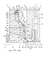
- the centrifugal compressor 1 of this embodiment includes a casing 2 and a rotor 7 that is rotatably supported in the casing 2.
- the rotor 7 includes a shaft 8 extending along the axis A and a plurality of impellers 9 fixed to the outer surface of the shaft 8.
- the direction in which the axis A of the rotor 7 extends is defined as the axis direction Da.
- a direction perpendicular to the axis A is a radial direction
- a side away from the axis A in the radial direction is called a radially outer side
- a side approaching the axis A in the radial direction is called a radially inner side.
- the right side in FIG. 1 is referred to as an axial direction one side Da1
- the left side in FIG. 1 is referred to as an axial direction other side Da2.
- the casing 2 includes a diaphragm 3 that surrounds the impeller 9 from the outer peripheral side, a first casing head 4 that is disposed with an interval between the other axial direction Da2 of the diaphragm 3, and an axial direction one side Da1 of the diaphragm 3. And the second casing head 5 disposed in a row, and a shielding plate 11 (shielding portion) fixed to the first casing head 4.
- the diaphragm 3 has a structure in which a plurality of diaphragm pieces 6 are arranged in the axial direction Da.
- the impeller 9 is attached to the outer surface of the shaft 8 and pumps a fluid G such as air flowing in from the other axial side Da2 toward the one axial direction Da1 using the centrifugal force toward the radially outer side.
- the casing 2 supports the rotor 7 rotatably.
- the casing 2 is formed with a flow path 12 through which the fluid G flows from the upstream side (the other axial side Da2) to the downstream side (the one axial direction Da1).
- the casing 2 is formed to have a substantially cylindrical outer shape, and the rotor 7 is disposed so as to penetrate the center.
- the first casing head 4 is provided with a first journal bearing 13 which is a bearing device that rotatably supports the end portion of the other axial direction Da2 of the rotor 7.
- the first journal bearing 13 is fixed to the first casing head 4.
- a thrust bearing 15 is provided on the other axial side Da2 of the first journal bearing 13.
- a dry gas seal 16 is provided on the radially inner side of the first casing head 4.
- the dry gas seal 16 is provided on one axial side Da1 of the first journal bearing 13.
- the dry gas seal 16 is a sealing device that performs sealing by ejecting a gas such as dry gas.
- the sealing device is not limited to the dry gas seal 16, and a device that can seal the gap between the first casing head 4 and the shaft 8 can be appropriately employed.
- a labyrinth seal may be installed as a sealing device between the first casing head 4 and the shaft 8.
- a seal fin 30 having a plurality of fins is provided on one side Da1 in the axial direction of the dry gas seal 16.
- a second journal bearing 14 discharge-side bearing device
- the second journal bearing 14 is fixed to the second casing head 5.
- a suction port 18 (suction channel) through which the fluid G flows from the outside is provided at the end of the other axial direction Da2 of the casing 2.
- the suction port 18 is formed by the shielding plate 11 and the diaphragm 3.
- a discharge port 19 (discharge flow path) through which the fluid G flows to the outside is provided at the end portion on one axial side of the casing 2.
- the discharge port 19 is formed by the discharge side shielding member 64 and the diaphragm 3.
- an internal space 20 that communicates with the suction port 18 and the discharge port 19 and repeats the diameter reduction and the diameter expansion.
- the internal space 20 functions as a space that houses the impeller 9 and also functions as the flow path 12 described above. That is, the suction port 18 and the discharge port 19 communicate with each other via the impeller 9 and the flow path 12.
- a plurality of impellers 9 are arranged at intervals in the axial direction Da.
- six impellers 9 are provided, but it is sufficient that at least one impeller 9 is provided.
- each impeller 9 includes a substantially disc-shaped hub 22 that gradually increases in diameter as it advances toward one axial direction Da ⁇ b> 1, and a plurality of blades 23 that are radially attached to the hub 22 and arranged in the circumferential direction. And a shroud 24 attached so as to cover the tip side of the plurality of blades 23 in the circumferential direction.
- the flow path 12 is formed so as to travel between the impellers 9 by moving in the axial direction Da while meandering in the radial direction so that the fluid G is compressed in stages by the plurality of impellers 9.
- the flow path 12 is mainly configured by a suction passage 25, a compression passage 26, a diffuser passage 27, and a return passage 28.
- a discharge scroll 29 (see FIG. 1) for discharging the fluid G from the discharge port is provided in the casing 2.
- the first casing head 4 is provided with an oil heater 60 which is a temperature adjusting device for heating the first casing head 4.
- the oil heater 60 includes a pipe 61 formed inside the first casing head 4, an oil heater main body 62 (temperature adjusting device main body) connected to the pipe 61, and the oil heater main body via the pipe 61. And a heat medium introduced to 62.
- the pipe 61 is connected to a heat medium supply source (not shown).
- the oil heater main body 62 has an annular shape and is formed so as to surround the rotor 7.
- the oil heater main body 62 is formed with a heat medium passage 63 through which the heat medium supplied through the pipe 61 circulates.
- the oil heater 60 can be supplied with lubricating oil supplied to the journal bearings 13 and 14 as a heat medium. By changing the temperature of the heat medium, the first casing head 4 can be heated or cooled.
- the suction inlet 18 of the centrifugal compressor 1 of this embodiment is demonstrated.
- the other axial side Da ⁇ b> 2 of the suction port 18 is formed by the shielding plate 11 fixed to the first casing head 4, and the first axial direction Da ⁇ b> 1 of the suction port 18 is the end surface 3 a of the diaphragm 3. Is formed by.
- a heat insulating space 10 is formed between the shielding plate 11 and the first casing head 4.
- the end surface (head end surface 4a) facing the one axial side Da1 of the first casing head 4 is an annular surface extending in the circumferential direction.
- the head end surface 4a is located on the radially outer side and is located on the radially inner side of the first flat surface portion 31 and the first flat surface portion 31 that are orthogonal to the axis A, and the diameter of the head end surface 4a decreases toward the one axial side Da1.
- a conical second inclined surface portion 34 having a diameter reduced toward the one axial side Da1.
- the first inclined surface portion 32 and the second flat surface portion 33 are connected by a cylindrical cylindrical portion 35 that is coaxial with the axis A.
- An outer edge protrusion 36 is formed at the radially outer end of the first flat surface portion 31.
- the outer edge protrusion 36 is an annular protrusion that protrudes from the radially outer end of the first flat surface portion 31 toward the one axial side Da1.
- the outer edge protruding portion 36 has a protruding portion main surface 37 that is parallel to the main surface of the first flat surface portion 31 and is offset from the main surface of the first flat surface portion 31 in the axial direction one side Da1. Yes.
- the shielding plate 11 is an annular plate-like member extending in the circumferential direction.
- the shielding plate 11 is connected to the fixing part 40 located on the radially outer side, the first disk part 41 formed on the one axial side Da1 of the fixing part 40, and the radially inner side of the first disk part 41.
- the first conical portion 42, the second disc portion 43 connected to the radially inner side of the first conical portion 42, and the second cone connected to the radially inner side of the second disc portion 43. Part 44.
- the shielding plate 11 is fixed to the first flat surface portion 31 of the head slope via the fixing portion 40.
- the shielding plate 11 has a cantilever structure that is fixed to the first flat surface portion 31 only by the fixing portion 40.
- the radially inner side of the shielding plate 11 is a free end and is not fixed.
- a gap C is provided between the radially inner end of the shielding plate 11 and the outer peripheral surface of the shaft 8.
- the main surface of the first disc portion 41 is orthogonal to the axis A.
- the first conical portion 42 has a conical shape with a diameter decreasing toward the one side Da1 in the axial direction.
- the main surface of the second disc portion 43 is orthogonal to the axis A.
- the second conical portion 44 has a conical shape with a diameter decreasing toward the one side Da1 in the axial direction.
- the fixing part 40 is an annular part having a rectangular cross section extending in the circumferential direction.
- a plurality of through holes 56 penetrating in the axial direction Da are formed in the fixed portion 40 (only one through hole 56 is shown in FIG. 2).
- the plurality of through holes 56 are formed at equal intervals in the circumferential direction.
- the shielding plate 11 is fixed to the first flat surface portion 31 by fastening a bolt 57 inserted through the through hole 56 into a female screw hole formed in the first flat surface portion 31.
- An annular convex portion 45 is formed on a fixed portion main surface 46 that is a surface facing the other axial direction Da2 of the fixed portion 40.
- the annular protrusion 45 is an annular protrusion that protrudes from the fixed portion main surface 46 to the other axial side Da2.
- the annular convex portion 45 is a surface parallel to the fixed portion main surface 46 and has an annular convex portion main surface 45 a that is offset from the fixed portion main surface 46 to the other axial direction Da 2.
- the fixing portion 40 of the shielding plate 11 and the first flat surface portion 31 of the first casing head 4 are connected by a so-called marking brazing structure. That is, an annular convex portion 45 having an outer diameter smaller than the outer diameter of the first casing head 4 is formed on the fixing portion 40 of the shielding plate 11. On the first flat surface portion 31 of the head end surface 4a, an outer edge protruding portion 36 that is an annular protrusion is formed. The outer peripheral surface 47 of the annular protrusion 45 is in surface contact with the inner peripheral surface 38 of the outer edge protrusion 36. That is, the shielding plate 11 is positioned by fitting the annular convex portion 45 inside the outer edge protruding portion 36 in the radial direction.
- the protrusion amount of the annular protrusion 45 from the fixed portion main surface 46 is equal to the protrusion amount of the outer edge protrusion portion 36 from the first flat surface portion 31.
- a seal ring 58 is provided on the first flat surface portion 31 facing the annular convex main surface 45a of the annular convex portion 45. That is, the seal ring 58 fitted into the annular groove formed in the first flat surface portion 31 is in close contact with the annular convex main surface 45a.
- annular space is formed between the head end surface 4 a of the first casing head 4 and the shielding plate 11.
- this annular space is referred to as a heat insulating space 10.
- the heat insulating space 10 is filled with a heat insulating material 49 that makes it difficult to transfer the heat of the shielding plate 11 to the first casing head 4. It is not always necessary to fill the heat insulating material 49.
- the first inclined surface portion 32 of the head end surface 4a and the first conical portion 42 of the shielding plate 11 are arranged in parallel with a predetermined interval in the axial direction Da.
- a space between the first slope portion 32 and the first conical portion 42 is referred to as a first heat insulating space 51.
- An interval between the first slope portion 32 and the first conical portion 42 is referred to as a first interval S1.
- a space between the second flat surface portion 33 and the second disc portion 43 is referred to as a second heat insulating space 52.
- An interval between the second flat surface portion 33 and the second disc portion 43 is referred to as a second interval S2.
- the 1st narrow part 53 by which the space
- the 2nd narrow part 54 in which the space
- the interval between the shielding plate 11 and the head end surface 4a in the first narrow portion 53 is referred to as a third interval S3.
- the interval between the shielding plate 11 and the head end surface 4a in the second narrow portion 54 is referred to as a fourth interval S4.
- the dimensions of the third interval S3, the fourth interval S4, and the gap C are substantially the same. That is, the dimensions of the third interval S3, the fourth interval S4, and the gap C are sufficiently smaller than the first interval S1 and the second interval S2.
- the axial direction one side Da ⁇ b> 1 of the discharge port 19 is formed by a discharge side shielding member 64 fixed to the second casing head 5, and the axial direction one side Da ⁇ b> 1 of the discharge port 19 is It is formed by the end face 3b.
- a discharge-side heat insulation space 65 is formed between the discharge-side shielding member 64 and the first casing head 4.
- the discharge side shielding member 64 is fixed to the second casing head 5 by welding.
- the discharge-side heat insulation space 65 is sealed by the welded portion 66.
- the discharge side shielding member 64 is an annular block-shaped member.
- interval S5) of the discharge side shielding member 64 and the 2nd casing head 5 is formed uniformly.
- the dimension of the fifth interval S5 can be, for example, approximately the same as the third interval S3 and the fourth interval S4 (see FIG. 2).
- interval S5 is not restricted to this, You may fill the heat insulating material 49 into the discharge side heat insulation space 65 by making it comparable as 1st space
- the heat insulation space 10 makes it difficult for the heat of the fluid G flowing through the suction port 18 to be transmitted to the first casing head 4, and the first casing head 4 can be prevented from being deformed by heat. .
- the first casing head 4 can suppress the occurrence of problems in the dry gas seal 16 and the first journal bearing 13. That is, it is possible to prevent the first casing head 4 from being deformed and affecting the dry gas seal 16 installed inside the first casing head 4 in the radial direction.
- the work of filling the heat insulating material 49 into the heat insulating space 10 can be easily performed. That is, the heat insulating material 49 can be reliably held by providing the narrow portions 53 and 54.
- the shielding plate 11 has a cantilever structure, and the clearance C is provided between the shielding plate 11 and the shaft 8, so that it flows through the suction port 18 as compared with the case where the radially inner side of the shielding plate 11 is fixed. Even when the shielding plate 11 is deformed by the heat of the fluid G, the stress generated in the shielding plate 11 can be relaxed. That is, when the radially outer end and the radially inner end of the shielding plate 11 are fixed, stress is generated inside the shielding plate 11 due to thermal deformation of the shielding plate 11. By using a cantilever structure, it is possible to suppress the occurrence of stress.
- the shielding plate 11 by fixing the shielding plate 11 using a seal brazing structure, centering when attaching the shielding plate 11 can be facilitated. That is, the gap C between the shielding plate 11 and the shaft 8 can be made constant.
- the first casing head 4 can be heated by providing the oil heater 60 in the first casing head 4. Thereby, the thermal deformation of the first casing head 4 can be suppressed. Further, the first casing head 4 can be cooled by flowing the refrigerant through the heat medium flow path 63 of the oil heater 60. That is, the first casing head 4 can be heated or cooled according to the temperature of the fluid G flowing through the suction port 18.
- discharge-side heat insulation space 65 makes it difficult for the heat of the fluid G flowing through the discharge port 19 to be transmitted to the second casing head 5, and the second casing head 5 can be prevented from being deformed by heat.
- the heat insulating space 10 may be a single space.
- centrifugal compressor 1B according to a second embodiment of the present invention will be described with reference to the drawings.
- differences from the first embodiment described above will be mainly described, and description of similar parts will be omitted.
- the fixing portion 40 of the shielding plate 11B of the present embodiment and the first flat surface portion 31 of the first casing head 4 are connected by a marking brazing structure as in the first embodiment.
- the portion that fits inside is formed on the shielding plate 11 side, whereas in the marking braze structure of this embodiment, the portion that fits inside is the first casing head. It differs in that it is formed on the 4 side.
- a second outer edge protrusion 36 ⁇ / b> B corresponding to the outer edge protrusion 36 (see FIG. 2) of the first embodiment is formed in the fixing portion 40 of the present embodiment.
- An annular recess 48 corresponding to the second outer edge protruding portion 36B is formed at the radially outer end of the first flat portion 31 of the present embodiment.
- the circumferential surface 50 of the annular recess 48 in the first flat surface portion 31 is in surface contact with the inner circumferential surface 55 of the second outer edge protruding portion 36B.
- the centrifugal compressor 1 ⁇ / b> C of the present embodiment includes a block-shaped first shielding member 68 and a block-shaped second shielding member 69 as a shielding portion that blocks the heat of the fluid G. ing. That is, unlike the shielding plate 11 of the first embodiment that is plate-shaped, the shielding portion of the present embodiment has a sufficient thickness in the axial direction Da.
- the first shielding member 68 is fixed to the radially outer side of the head end surface 4 a of the first casing head 4.
- the 2nd shielding member 69 is being fixed to the radial inside of the head end surface 4a.
- the 1st heat insulation space 51 which is the slit-shaped space extended in the circumferential direction is formed.
- the first heat insulating space 51 is sealed by a seal ring 72 that is a sealing device. That is, the seal ring 72 fitted in an annular groove formed on the head end surface 4a is in close contact with the surface of the first shielding member 68 facing the other axial direction Da2.
- the first shielding member 68 is fixed to the first casing head 4 with bolts 57.
- a second heat insulation space 52 extending in the circumferential direction is formed between the second shielding member 69 and the first casing head 4.
- the second shielding member 69 is joined to the first casing head 4 by welding.
- the outer side in the radial direction of the second heat insulating space 52 is sealed with a welded portion 73.
- the fixing method of the 1st shielding member 68 and the 2nd shielding member 69 is not restricted to an above-described method, For example, you may fix the 1st shielding member 68 to the 1st casing head 4 by welding. According to such a structure, the rigidity of a shielding part can be improved more.
- the heat insulation spaces 70 and 71 are sealed by the seal ring 72 and the welding part 73, the heat insulation spaces 70 and 71 can be made into a vacuum or a state close to a vacuum.
- this embodiment it was set as the structure which provided two shielding members and provided two heat insulation spaces, but it is not restricted to this, As a structure which seals one heat insulation space using one shielding member Good.
Abstract
軸線に沿って延びるシャフトと、シャフトの外面に固定されて軸線方向一方側に向かって流入する流体を軸線の径方向外側に圧送するインペラとを有するロータと、インペラを外周側から囲うダイアフラムと、ダイアフラムの軸線方向他方側に間隔をあけて配置された第一ケーシングヘッドと、第一ケーシングヘッドとシャフトとの間に配置されたシール装置と、シール装置よりも軸線方向他方側に配置されて、第一ケーシングヘッドとシャフトとの間に配置された軸受装置と、第一ケーシングヘッドの軸線方向一方側に固定されて、ダイアフラムとともにインペラに流体を導入する吸込流路を画成するとともに、第一ケーシングヘッドとの間に断熱空間を画成する遮蔽部と、を備える遠心圧縮機。
Description
本発明は、インペラを用いて流体を圧縮する遠心圧縮機に関する。
周知のように、遠心圧縮機は、回転するインペラの半径方向に空気やガスなどの流体を通り抜けさせ、その際に発生する遠心力を利用してそれら流体を圧縮する。この種の遠心圧縮機において、インペラを軸線方向に多段に備え、流体を段階的に圧縮する多段式の遠心圧縮機が知られている。
具体的には、遠心圧縮機は、ケーシングと、ケーシング内に収容されたロータとを備えている。ロータは、シャフトと、シャフトの外面に固定されたインペラと、を有している。ケーシングの吸込口から吸引された流体は、インペラにて遠心力が付与され、その運動エネルギーをディフューザ及びスクロール部で圧力エネルギーに変換する。流体は、ケーシングの排出口から送出される。
各種プラントの要求に合わせて、様々な遠心圧縮機が製造されているが、近年、例えば、LNGボイルオフガス向けの圧縮機として、極低温(例えば、-160℃)の流体を圧縮する遠心圧縮機の開発もなされている(例えば、特許文献1参照)。
ところで、例えば、極低温の流体を圧縮する遠心圧縮機においては、流体が吸引されると過度の温度変化に伴い、吸込口に隣接するケーシングヘッドが変形することがあった。ケーシングヘッドが変形することによって、ケーシングヘッドとロータとの間をシールするシール装置の機能が十分に果たされないことがあった。また、ケーシングヘッドの変形によって、ケーシングヘッドに設けられてロータを回転可能に支持する軸受の不具合に繋がる可能性があった。
本発明は、シール装置及び軸受装置に不具合が発生することを抑制することができる遠心圧縮機を提供することを目的とする。
本発明の第一の態様によれば、遠心圧縮機は、軸線に沿って延びるシャフトと、前記シャフトの外面に固定されて軸線方向一方側に向かって流入する流体を前記軸線の径方向外側に圧送するインペラとを有するロータと、前記インペラを外周側から囲うダイアフラムと、前記ダイアフラムの前記軸線方向他方側に間隔をあけて配置された第一ケーシングヘッドと、前記第一ケーシングヘッドと前記シャフトとの間に配置されたシール装置と、前記シール装置よりも前記軸線方向他方側に配置されて、前記第一ケーシングヘッドと前記シャフトとの間に配置された軸受装置と、前記第一ケーシングヘッドの前記軸線方向一方側に固定されて、前記ダイアフラムとともに前記インペラに流体を導入する吸込流路を画成するとともに、前記第一ケーシングヘッドとの間に断熱空間を画成する遮蔽部と、を備える。
このような構成によれば、断熱空間によって、吸込流路を流れる流体の熱が第一ケーシングヘッドに伝達しにくくなり、第一ケーシングヘッドが熱により変形することを抑制することができる。これにより、シール装置及び軸受装置に不具合が発生することを抑制することができる。
上記遠心圧縮機において、前記遮蔽部は、前記第一ケーシングヘッドの径方向外側の端部のみに固定され、前記遮蔽部の径方向内側の端部と前記シャフトの外周面との間に隙間が設けられるように形成されてよい。
このような構成によれば、吸込流路を流れる流体の熱により遮蔽部が変形した場合においても、遮蔽部の径方向内側を固定する場合と比較して、遮蔽部に生じる応力を緩和することができる。
上記遠心圧縮機において、前記第一ケーシングヘッドの内部に形成されている管路と、前記管路と接続された温度調整装置本体と、前記管路を介して前記温度調整装置本体に導入される熱媒体と、を有する温度調整装置を備えてよい。
このような構成によれば、吸込流路を流れる流体の温度に応じて、第一ケーシングヘッドを加熱したり、冷却したりすることができる。これにより、吸込流路を流れる流体の熱が第一ケーシングヘッドに伝達した場合においても、第一ケーシングヘッドの熱変形を抑制することができる。
上記遠心圧縮機において、前記ダイアフラムの前記軸線方向一方側に間隔をあけて配置された第二ケーシングヘッドと、前記第二ケーシングヘッドと前記シャフトとの間に配置された排出側軸受装置と、前記第二ケーシングヘッドの前記軸線方向他方側に固定されて、前記ダイアフラムとともに前記インペラから流体を排出する排出流路を画成するとともに、前記第二ケーシングヘッドとの間に排出側断熱空間を画成する第二遮蔽部と、を備えてよい。
このような構成によれば、排出流路を流れる流体の熱が第二ケーシングヘッドに伝達しにくくなり、第二ケーシングヘッドが熱により変形することを抑制することができる。これにより、排出側軸受装置に不具合が発生することを抑制することができる。
上記遠心圧縮機において、前記第一断熱空間と前記第二断熱空間の少なくとも一方に充填された断熱材を備えてよい。
このような構成によれば、さらに、吸込流路、排出流路を流れる流体の熱を第一ケーシングヘッドに伝達しにくくすることができる。
上記遠心圧縮機において、前記遮蔽部は、径方向外側の端部及び径方向内側の端部が第一ケーシングヘッドの軸線方向一方側に固定された遮蔽部材を有し、前記断熱空間は、前記遮蔽部材によって密封されてよい。
このような構成によれば、断熱空間と吸込流路とを完全に遮断することができる。また、遮蔽部の剛性をより高めることができる。
上記遠心圧縮機において、前記遮蔽部材と、前記第一ケーシングヘッドとの複数の固定部うち少なくとも一ヶ所に設けられた密封装置を備えてよい。
このような構成によれば、断熱空間の密封度を向上させることができる。
このような構成によれば、断熱空間によって、吸込流路を流れる流体の熱が第一ケーシングヘッドに伝達しにくくなり、第一ケーシングヘッドが熱により変形することを抑制することができる。これにより、シール装置及び軸受装置に不具合が発生することを抑制することができる。
本発明の実施形態について図面を参照して詳細に説明する。本実施形態では、遠心圧縮機の一例として、インペラを複数備えた多段式の遠心圧縮機を例に挙げて説明する。
図1に示すように、本実施形態の遠心圧縮機1は、ケーシング2と、ケーシング2内で回転自在に支持されているロータ7を備えている。ロータ7は、軸線Aに沿って延びるシャフト8と、シャフト8の外面に固定されている複数のインペラ9と、を有している。
以下の説明において、ロータ7の軸線Aが延びている方向を軸線方向Daとする。また、軸線Aに直交する方向を径方向とし、径方向で軸線Aから遠ざかる側を径方向外側と呼び、径方向で軸線Aに近づく側を径方向内側と呼ぶ。軸線方向Daであって、図1の右側を軸線方向一方側Da1、図1の左側を軸線方向他方側Da2と呼ぶ。
図1に示すように、本実施形態の遠心圧縮機1は、ケーシング2と、ケーシング2内で回転自在に支持されているロータ7を備えている。ロータ7は、軸線Aに沿って延びるシャフト8と、シャフト8の外面に固定されている複数のインペラ9と、を有している。
以下の説明において、ロータ7の軸線Aが延びている方向を軸線方向Daとする。また、軸線Aに直交する方向を径方向とし、径方向で軸線Aから遠ざかる側を径方向外側と呼び、径方向で軸線Aに近づく側を径方向内側と呼ぶ。軸線方向Daであって、図1の右側を軸線方向一方側Da1、図1の左側を軸線方向他方側Da2と呼ぶ。
ケーシング2は、インペラ9を外周側から囲うダイアフラム3と、ダイアフラム3の軸線方向他方側Da2に間隔をあけて配置された第一ケーシングヘッド4と、ダイアフラム3の軸線方向一方側Da1に間隔をあけて配置された第二ケーシングヘッド5と、第一ケーシングヘッド4に固定されている遮蔽板11(遮蔽部)と、を有している。
ダイアフラム3は、複数のダイアフラム片6を軸線方向Daに配列させた構造である。
ダイアフラム3は、複数のダイアフラム片6を軸線方向Daに配列させた構造である。
インペラ9は、シャフト8の外面に取り付けられて遠心力を利用して軸線方向他方側Da2から軸線方向一方側Da1に向けて流入する空気などの流体Gを径方向外側に向けて圧送する。
ケーシング2は、ロータ7を回転可能に支持する。ケーシング2には、流体Gを上流側(軸線方向他方側Da2)から下流側(軸線方向一方側Da1)に流す流路12が形成されている。
ケーシング2は、ロータ7を回転可能に支持する。ケーシング2には、流体Gを上流側(軸線方向他方側Da2)から下流側(軸線方向一方側Da1)に流す流路12が形成されている。
ケーシング2は、略円柱状の外郭をなすように形成され、中心を貫くようにロータ7が配置されている。第一ケーシングヘッド4にはロータ7の軸線方向他方側Da2の端部を回転可能に支持する軸受装置である第一ジャーナル軸受13が設けられている。第一ジャーナル軸受13は、第一ケーシングヘッド4に固定されている。第一ジャーナル軸受13の軸線方向他方側Da2にはスラスト軸受15が設けられている。
第一ケーシングヘッド4の径方向内側には、ドライガスシール16が設けられている。ドライガスシール16は、第一ジャーナル軸受13の軸線方向一方側Da1に設けられている。ドライガスシール16は、ドライガスなどの気体を噴出させることによって封止を行うシール装置である。なお、シール装置としては、ドライガスシール16に限らず、第一ケーシングヘッド4とシャフト8との間の隙間をシールできるものを適宜採用することができる。例えば、第一ケーシングヘッド4とシャフト8との間に、シール装置としてラビリンスシールを設置してもよい。
ドライガスシール16の軸線方向一方側Da1には、複数のフィンを有するシールフィン30が設けられている。
第二ケーシングヘッド5の径方向内側には、ロータ7の軸線方向一方側Da1の端部を回転可能に支持する第二ジャーナル軸受14(排出側軸受装置)が設けられている。第二ジャーナル軸受14は、第二ケーシングヘッド5に固定されている。
第二ケーシングヘッド5の径方向内側には、ロータ7の軸線方向一方側Da1の端部を回転可能に支持する第二ジャーナル軸受14(排出側軸受装置)が設けられている。第二ジャーナル軸受14は、第二ケーシングヘッド5に固定されている。
ケーシング2の軸線方向他方側Da2の端部には、流体Gを外部から流入させる吸込口18(吸込流路)が設けられている。吸込口18は、遮蔽板11とダイアフラム3とによって形成されている。
ケーシング2の軸方向一方側の端部には、流体Gが外部に流出する排出口19(排出流路)が設けられている。排出口19は、排出側遮蔽部材64とダイアフラム3とによって形成されている。
ケーシング2内には、吸込口18及び排出口19にそれぞれ連通し、縮径及び拡径を繰り返す内部空間20が設けられている。内部空間20は、インペラ9を収容する空間として機能すると共に上述した流路12としても機能する。即ち、吸込口18と排出口19とは、インペラ9及び流路12を介して連通している。
ケーシング2の軸方向一方側の端部には、流体Gが外部に流出する排出口19(排出流路)が設けられている。排出口19は、排出側遮蔽部材64とダイアフラム3とによって形成されている。
ケーシング2内には、吸込口18及び排出口19にそれぞれ連通し、縮径及び拡径を繰り返す内部空間20が設けられている。内部空間20は、インペラ9を収容する空間として機能すると共に上述した流路12としても機能する。即ち、吸込口18と排出口19とは、インペラ9及び流路12を介して連通している。
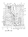
インペラ9は、軸線方向Daに間隔を空けて複数配列されている。なお、図示例において、インペラ9は六つ設けられているが少なくとも一つ設けられていればよい。図2に示すように、各々のインペラ9は、軸線方向一方側Da1に進むにつれて漸次拡径した略円盤状のハブ22と、ハブ22に放射状に取り付けられ、周方向に並んだ複数の羽根23と、複数の羽根23の先端側を周方向に覆うように取り付けられたシュラウド24と、によって構成されている。
流路12は、流体Gが複数のインペラ9によって段階的に圧縮されるように、径方向に蛇行しながら軸線方向Daに進行して各々のインペラ9間を繋ぐように形成されている。流路12は、主に吸込通路25と、圧縮通路26と、ディフューザ通路27と、リターン通路28と、によって構成されている。
ケーシング2内には、吐出口から流体Gを吐出するための吐出スクロール29(図1参照)が設けられている。
ケーシング2内には、吐出口から流体Gを吐出するための吐出スクロール29(図1参照)が設けられている。
また、第一ケーシングヘッド4には、第一ケーシングヘッド4を加熱する温度調整装置であるオイルヒータ60が設けられている。オイルヒータ60は、第一ケーシングヘッド4の内部に形成されている管路61と、管路61と接続されたオイルヒータ本体62(温度調整装置本体)と、管路61を介してオイルヒータ本体62に導入される熱媒体と、を有している。
管路61は図示しない熱媒体供給源と接続されている。オイルヒータ本体62は環状をなし、ロータ7を囲うように形成されている。オイルヒータ本体62には、管路61を介して供給される熱媒体が循環する熱媒体流路63が形成されている。例えば、オイルヒータ60には、熱媒体としてジャーナル軸受13,14に供給する潤滑油を供給することができる。熱媒体の温度を変更することによって、第一ケーシングヘッド4を加熱したり冷却したりすることができる。
次に、本実施形態の遠心圧縮機1の吸込口18の詳細構造について説明する。
図2に示すように、吸込口18の軸線方向他方側Da2は、第一ケーシングヘッド4に固定された遮蔽板11によって形成され、吸込口18の軸線方向一方側Da1は、ダイアフラム3の端面3aによって形成されている。遮蔽板11と第一ケーシングヘッド4との間には、断熱空間10が形成されている。
図2に示すように、吸込口18の軸線方向他方側Da2は、第一ケーシングヘッド4に固定された遮蔽板11によって形成され、吸込口18の軸線方向一方側Da1は、ダイアフラム3の端面3aによって形成されている。遮蔽板11と第一ケーシングヘッド4との間には、断熱空間10が形成されている。
第一ケーシングヘッド4の軸線方向一方側Da1を向く端面(ヘッド端面4a)は、周方向に延在する環状の面である。ヘッド端面4aは、径方向外側に位置し、軸線Aに直交する面である第一平面部31と、第一平面部31の径方向内側に位置し、軸線方向一方側Da1に向かうに従って縮径する円錐状の第一斜面部32と、第一斜面部32の径方向内側に位置し、軸線Aに直交する面である第二平面部33と、第二平面部33の径方向内側に位置し、軸線方向一方側Da1に向かうに従って縮径する円錐状の第二斜面部34とを有している。
第一斜面部32と、第二平面部33とは、軸線Aと同軸をなす円筒状の円筒部35によって接続されている。
第一平面部31の径方向外側端部には、外縁突出部36が形成されている。外縁突出部36は、第一平面部31の径方向外側の端部から軸線方向一方側Da1に突出する環状の突起である。外縁突出部36は、第一平面部31の主面と平行な面であって、第一平面部31の主面に対して軸線方向一方側Da1にオフセットした突出部主面37を有している。
第一平面部31の径方向外側端部には、外縁突出部36が形成されている。外縁突出部36は、第一平面部31の径方向外側の端部から軸線方向一方側Da1に突出する環状の突起である。外縁突出部36は、第一平面部31の主面と平行な面であって、第一平面部31の主面に対して軸線方向一方側Da1にオフセットした突出部主面37を有している。
遮蔽板11は、周方向に延在する環状の板状部材である。遮蔽板11は、径方向外側に位置する固定部40と、固定部40の軸線方向一方側Da1に形成されている第一円板部41と、第一円板部41の径方向内側に接続されている第一円錐部42と、第一円錐部42の径方向内側に接続されている第二円板部43と、第二円板部43の径方向内側に接続されている第二円錐部44と、を有している。
遮蔽板11は、固定部40を介してヘッド斜面の第一平面部31に固定される。遮蔽板11は、固定部40のみによって第一平面部31に固定される片持ち構造である。遮蔽板11の径方向内側は自由端であり、固定されない。遮蔽板11の径方向内側の端部とシャフト8の外周面との間には、隙間Cが設けられている。
第一円板部41の主面は、軸線Aに直交する。第一円錐部42は、軸線方向一方側Da1に向かうに従って縮径する円錐状をなしている。第二円板部43の主面は、軸線Aと直交する。第二円錐部44は、軸線方向一方側Da1に向かうに従って縮径する円錐状をなしている。
第一円板部41の主面は、軸線Aに直交する。第一円錐部42は、軸線方向一方側Da1に向かうに従って縮径する円錐状をなしている。第二円板部43の主面は、軸線Aと直交する。第二円錐部44は、軸線方向一方側Da1に向かうに従って縮径する円錐状をなしている。
固定部40は、周方向に延在する断面矩形状の環状の部位である。固定部40には、軸線方向Daに貫通する複数の貫通孔56が形成されている(図2には一つの貫通孔56のみを示す)。複数の貫通孔56は、周方向に等間隔に形成されている。遮蔽板11は、貫通孔56に挿通されたボルト57を第一平面部31に形成された雌ネジ孔に締結することによって、第一平面部31に固定される。
固定部40の軸線方向他方側Da2を向く面である固定部主面46には、環状凸部45が形成されている。環状凸部45は、固定部主面46から軸線方向他方側Da2に突出する環状の突起である。環状凸部45は、固定部主面46と平行な面であって、固定部主面46に対して軸線方向他方側Da2にオフセットした環状凸部主面45aを有している。
遮蔽板11の固定部40と、第一ケーシングヘッド4の第一平面部31とは、所謂、印ろう構造によって接続される。即ち、遮蔽板11の固定部40には、第一ケーシングヘッド4の外径よりも小さい外径の環状凸部45が形成されている。ヘッド端面4aの第一平面部31には、環状の突起である外縁突出部36が形成されている。
環状凸部45の外周面47は、外縁突出部36の内周面38と面接触する。即ち、遮蔽板11は、環状凸部45が外縁突出部36の径方向内側に嵌ることによって位置決めされる。環状凸部45の固定部主面46からの突出量と、外縁突出部36の第一平面部31からの突出量は等しい。これにより、固定部40の固定部主面46と、第一平面部31の突出部主面37とは面接触し、固定部40の環状凸部主面45aと第一平面部31とは面接触する。
環状凸部45の外周面47は、外縁突出部36の内周面38と面接触する。即ち、遮蔽板11は、環状凸部45が外縁突出部36の径方向内側に嵌ることによって位置決めされる。環状凸部45の固定部主面46からの突出量と、外縁突出部36の第一平面部31からの突出量は等しい。これにより、固定部40の固定部主面46と、第一平面部31の突出部主面37とは面接触し、固定部40の環状凸部主面45aと第一平面部31とは面接触する。
環状凸部45の環状凸部主面45aに面する第一平面部31にはシールリング58が設けられている。即ち、第一平面部31に形成された環状の溝に嵌め込まれたシールリング58が環状凸部主面45aに密着している。
第一ケーシングヘッド4のヘッド端面4aと、遮蔽板11との間には、環状の空間が形成されている。以下、この環状空間を断熱空間10と呼ぶ。
断熱空間10には、遮蔽板11の熱を第一ケーシングヘッド4に伝達し難くする断熱材49が隙間なく充填されている。なお、断熱材49は必ずしも充填する必要はない。
断熱空間10には、遮蔽板11の熱を第一ケーシングヘッド4に伝達し難くする断熱材49が隙間なく充填されている。なお、断熱材49は必ずしも充填する必要はない。
ヘッド端面4aの第一斜面部32と、遮蔽板11の第一円錐部42とは、軸線方向Daに所定の間隔をあけて平行に配置されている。第一斜面部32と第一円錐部42との間の空間を第一断熱空間51と呼ぶ。第一斜面部32と第一円錐部42との間隔を第一間隔S1と呼ぶ。
同様に、第二平面部33と第二円板部43との間の空間を第二断熱空間52と呼ぶ。第二平面部33と第二円板部43との間隔を第二間隔S2と呼ぶ。
同様に、第二平面部33と第二円板部43との間の空間を第二断熱空間52と呼ぶ。第二平面部33と第二円板部43との間隔を第二間隔S2と呼ぶ。
第一断熱空間51と第二断熱空間52との間には、遮蔽板11とヘッド端面4aとの間隔が第一間隔S1及び第二間隔S2よりも狭く形成された第一狭隘部53が設けられている。
第二断熱空間52と隙間Cとの間には、遮蔽板11とヘッド端面4aとの間隔が第一間隔S1及び第二間隔S2よりも狭く形成された第二狭隘部54が設けられている。
第二断熱空間52と隙間Cとの間には、遮蔽板11とヘッド端面4aとの間隔が第一間隔S1及び第二間隔S2よりも狭く形成された第二狭隘部54が設けられている。
第一狭隘部53における遮蔽板11とヘッド端面4aとの間隔を第三間隔S3と呼ぶ。
第二狭隘部54における遮蔽板11とヘッド端面4aとの間隔を第四間隔S4と呼ぶ。
第三間隔S3と第四間隔S4と隙間Cの寸法は、略同一である。即ち、第三間隔S3と第四間隔S4と隙間Cの寸法は、第一間隔S1及び第二間隔S2よりも十分に小さい。
第二狭隘部54における遮蔽板11とヘッド端面4aとの間隔を第四間隔S4と呼ぶ。
第三間隔S3と第四間隔S4と隙間Cの寸法は、略同一である。即ち、第三間隔S3と第四間隔S4と隙間Cの寸法は、第一間隔S1及び第二間隔S2よりも十分に小さい。
次に、本実施形態の遠心圧縮機1の排出口19の詳細構造について説明する。
図3に示すように、排出口19の軸線方向一方側Da1は、第二ケーシングヘッド5に固定された排出側遮蔽部材64によって形成され、排出口19の軸線方向一方側Da1は、ダイアフラム3の端面3bによって形成されている。排出側遮蔽部材64と第一ケーシングヘッド4との間には、排出側断熱空間65が形成されている。
図3に示すように、排出口19の軸線方向一方側Da1は、第二ケーシングヘッド5に固定された排出側遮蔽部材64によって形成され、排出口19の軸線方向一方側Da1は、ダイアフラム3の端面3bによって形成されている。排出側遮蔽部材64と第一ケーシングヘッド4との間には、排出側断熱空間65が形成されている。
排出側遮蔽部材64は、溶接によって第二ケーシングヘッド5に固定されている。排出側断熱空間65は、溶接部66によって封止されている。
排出側遮蔽部材64は、環状をなすブロック状の部材である。排出側遮蔽部材64と第二ケーシングヘッド5との間隔(第五間隔S5)は、一様に形成されている。第五間隔S5の寸法は、例えば、第三間隔S3や第四間隔S4(図2参照)と同程度とすることができる。
第五間隔S5の寸法はこれに限ることはなく、第一間隔S1と同程度として、排出側断熱空間65に断熱材49を充填してもよい。
排出側遮蔽部材64は、環状をなすブロック状の部材である。排出側遮蔽部材64と第二ケーシングヘッド5との間隔(第五間隔S5)は、一様に形成されている。第五間隔S5の寸法は、例えば、第三間隔S3や第四間隔S4(図2参照)と同程度とすることができる。
第五間隔S5の寸法はこれに限ることはなく、第一間隔S1と同程度として、排出側断熱空間65に断熱材49を充填してもよい。
上記実施形態によれば、断熱空間10によって、吸込口18を流れる流体Gの熱が第一ケーシングヘッド4に伝達しにくくなり、第一ケーシングヘッド4が熱により変形することを抑制することができる。
これにより、ドライガスシール16及び第一ジャーナル軸受13に不具合が発生することを抑制することができる。即ち、第一ケーシングヘッド4が変形し、第一ケーシングヘッド4の径方向内側に設置されるドライガスシール16にその変形の影響が及ぶことを防止することができる。また、第一ケーシングヘッド4が変形し、第一ケーシングヘッド4の径方向内側に設置される第一ジャーナル軸受13のクリアランスが変化することを抑制することができる。
これにより、ドライガスシール16及び第一ジャーナル軸受13に不具合が発生することを抑制することができる。即ち、第一ケーシングヘッド4が変形し、第一ケーシングヘッド4の径方向内側に設置されるドライガスシール16にその変形の影響が及ぶことを防止することができる。また、第一ケーシングヘッド4が変形し、第一ケーシングヘッド4の径方向内側に設置される第一ジャーナル軸受13のクリアランスが変化することを抑制することができる。
また、狭隘部53,54を設けることによって、断熱材49を断熱空間10に充填する作業を容易に行うことができる。即ち、狭隘部53,54を設けることによって、断熱材49を確実に保持することができる。
また、遮蔽板11を片持ち構造とし、遮蔽板11とシャフト8との間に隙間Cを設けたことによって、遮蔽板11の径方向内側を固定する場合と比較して、吸込口18を流れる流体Gの熱により遮蔽板11が変形した場合においても、遮蔽板11に生じる応力を緩和することができる。即ち、遮蔽板11の径方向外側の端部と径方向内側の端部とを固定する場合においては、遮蔽板11の熱変形に伴い、遮蔽板11の内部に応力が生じるが、遮蔽板11を片持ち構造とすることによって、応力が生じることを抑制することができる。
また、印ろう構造を用いて遮蔽板11を固定したことによって、遮蔽板11の取り付けの際のセンタリングを容易とすることができる。即ち、遮蔽板11とシャフト8との間の隙間Cを一定にすることができる。
また、第一ケーシングヘッド4にオイルヒータ60を設けたことによって、第一ケーシングヘッド4を加熱することができる。これにより、第一ケーシングヘッド4の熱変形を抑制することができる。
また、オイルヒータ60の熱媒体流路63に冷媒を流すことによって、第一ケーシングヘッド4を冷却することができる。即ち、吸込口18を流れる流体Gの温度に応じて、第一ケーシングヘッド4を加熱したり、冷却したりすることができる。
また、オイルヒータ60の熱媒体流路63に冷媒を流すことによって、第一ケーシングヘッド4を冷却することができる。即ち、吸込口18を流れる流体Gの温度に応じて、第一ケーシングヘッド4を加熱したり、冷却したりすることができる。
また、排出側断熱空間65によって、排出口19を流れる流体Gの熱が第二ケーシングヘッド5に伝達しにくくなり、第二ケーシングヘッド5が熱により変形することを抑制することができる。
なお、上記実施形態では、狭隘部53,54を二つ設ける構成としたがこれに限ることはない。例えば、第二狭隘部54のみを設けて、断熱空間10を一つの空間としてもよい。
(第二実施形態)
以下、本発明の第二実施形態の遠心圧縮機1Bを図面に基づいて説明する。なお、本実施形態では、上述した第一実施形態との相違点を中心に述べ、同様の部分についてはその説明を省略する。
本実施形態の遮蔽板11Bの固定部40と第一ケーシングヘッド4の第一平面部31とは、第一実施形態と同様に、印ろう構造によって接続される。第一実施形態の遠心圧縮機1においては、内側に嵌り込む部位が遮蔽板11側に形成されているのに対し、本実施形態の印ろう構造は、内側に嵌り込む部位が第一ケーシングヘッド4側に形成されている点が異なる。
以下、本発明の第二実施形態の遠心圧縮機1Bを図面に基づいて説明する。なお、本実施形態では、上述した第一実施形態との相違点を中心に述べ、同様の部分についてはその説明を省略する。
本実施形態の遮蔽板11Bの固定部40と第一ケーシングヘッド4の第一平面部31とは、第一実施形態と同様に、印ろう構造によって接続される。第一実施形態の遠心圧縮機1においては、内側に嵌り込む部位が遮蔽板11側に形成されているのに対し、本実施形態の印ろう構造は、内側に嵌り込む部位が第一ケーシングヘッド4側に形成されている点が異なる。
図4に示すように、本実施形態の固定部40には、第一実施形態の外縁突出部36(図2参照)に相当する第二外縁突出部36Bが形成されている。本実施形態の第一平面部31の径方向外側の端部には、第二外縁突出部36Bに対応する環状凹部48が形成されている。第一平面部31に環状凹部48の周面50は、第二外縁突出部36Bの内周面55と面接触する。
上記実施形態によれば、吸込口18から導入される流体Gが高温であり、遮蔽板11Bが熱により膨張した場合、固定部40の第二外縁突出部36Bは、径方向外側に移動する。これにより、遮蔽板11B全体も径方向外側に移動するため、遮蔽板11Bの径方向内側の端部がシャフト8に接触するのを防止することができる。
(第三実施形態)
以下、本発明の第三実施形態の遠心圧縮機1Cを図面に基づいて説明する。なお、本実施形態では、上述した第一実施形態との相違点を中心に述べ、同様の部分についてはその説明を省略する。
図5に示すように、本実施形態の遠心圧縮機1Cは、流体Gの熱を遮断する遮蔽部として、ブロック形状の第一遮蔽部材68と、ブロック形状の第二遮蔽部材69とを有している。即ち、本実施形態の遮蔽部は、板状である第一実施形態の遮蔽板11と異なり、軸線方向Daに十分な厚みを有している。第一遮蔽部材68は、第一ケーシングヘッド4のヘッド端面4aの径方向外側に固定されている。第二遮蔽部材69は、ヘッド端面4aの径方向内側に固定されている。
第一遮蔽部材68と第一ケーシングヘッド4との間には、周方向に延在するスリット状の空間である第一断熱空間51が形成されている。第一断熱空間51は密封装置であるシールリング72によって封止されている。即ち、ヘッド端面4aに形成された環状の溝に嵌め込まれたシールリング72が第一遮蔽部材68の軸線方向他方側Da2を向く面に密着している。第一遮蔽部材68は、ボルト57によって第一ケーシングヘッド4に固定されている。
第二遮蔽部材69と第一ケーシングヘッド4との間には、周方向に延在する第二断熱空間52が形成されている。第二遮蔽部材69は、溶接によって第一ケーシングヘッド4に接合されている。第二断熱空間52の径方向外側は溶接部73によって封止されている。
なお、第一遮蔽部材68、第二遮蔽部材69の固定方法は、上記した方法に限ることはなく、例えば、第一遮蔽部材68を溶接によって第一ケーシングヘッド4に固定してもよい。
このような構成によれば、遮蔽部の剛性をより高めることができる。また、断熱空間70,71がシールリング72や溶接部73によって密封されているため、断熱空間70,71を真空、あるいは真空に近い状態にすることができる。
なお、第一遮蔽部材68、第二遮蔽部材69の固定方法は、上記した方法に限ることはなく、例えば、第一遮蔽部材68を溶接によって第一ケーシングヘッド4に固定してもよい。
このような構成によれば、遮蔽部の剛性をより高めることができる。また、断熱空間70,71がシールリング72や溶接部73によって密封されているため、断熱空間70,71を真空、あるいは真空に近い状態にすることができる。
なお、本実施形態においては、遮蔽部材を二つ設けて、断熱空間を二つ設ける構成としたがこれに限ることはなく、一つの遮蔽部材を用いて、一つの断熱空間を密閉する構成としてよい。
以上、本発明の実施形態について詳細を説明したが、本発明の技術的思想を逸脱しない範囲内において、種々の変更を加えることが可能である。
例えば、上記実施形態では、排出口19側にも断熱空間を設ける構成としたが、これに限ることはない。即ち、排出側断熱空間65は必ずしも設ける必要はない。
例えば、上記実施形態では、排出口19側にも断熱空間を設ける構成としたが、これに限ることはない。即ち、排出側断熱空間65は必ずしも設ける必要はない。
1,1B,1C 遠心圧縮機
2 ケーシング
3 ダイアフラム
4 第一ケーシングヘッド
4a ヘッド端面
5 第二ケーシングヘッド
7 ロータ
8 シャフト
9 インペラ
10 断熱空間
11,11B 遮蔽板
12 流路
13 第一ジャーナル軸受
14 第二ジャーナル軸受
15 スラスト軸受
16 ドライガスシール(シール装置)
18 吸込口(吸込流路)
19 排出口(排出流路)
20 内部空間
30 シールフィン
31 第一平面部
32 第一斜面部
33 第二平面部
34 第二斜面部
35 円筒部
36 外縁突出部
36B 第二外縁突出部
37 突出部主面
40 固定部
41 第一円板部
42 第一円錐部
43 第二円板部
44 第二円錐部
45 環状凸部
45a 環状凸部主面
46 固定部主面
48 環状凹部
49 断熱材
51 第一断熱空間
52 第二断熱空間
53 第一狭隘部
54 第二狭隘部
60 オイルヒータ(温度調整装置)
62 オイルヒータ本体
64 排出側遮蔽部材
65 排出側断熱空間
66 溶接部
68 第一遮蔽部材
69 第二遮蔽部材
70 第一断熱空間
71 第二断熱空間
72 シールリング(密封装置)
73 溶接部
A 軸線
C 隙間
Da 軸線方向
G 流体
S1 第一間隔
S2 第二間隔
S3 第三間隔
S4 第四間隔
Claims (7)
- 軸線に沿って延びるシャフトと、前記シャフトの外面に固定されて軸線方向一方側に向かって流入する流体を前記軸線の径方向外側に圧送するインペラとを有するロータと、
前記インペラを外周側から囲うダイアフラムと、
前記ダイアフラムの前記軸線方向他方側に間隔をあけて配置された第一ケーシングヘッドと、
前記第一ケーシングヘッドと前記シャフトとの間に配置されたシール装置と、
前記シール装置よりも前記軸線方向他方側に配置されて、前記第一ケーシングヘッドと前記シャフトとの間に配置された軸受装置と、
前記第一ケーシングヘッドの前記軸線方向一方側に固定されて、前記ダイアフラムとともに前記インペラに流体を導入する吸込流路を画成するとともに、前記第一ケーシングヘッドとの間に断熱空間を画成する遮蔽部と、
を備える遠心圧縮機。 - 前記遮蔽部は、前記第一ケーシングヘッドの径方向外側の端部のみに固定され、前記遮蔽部の径方向内側の端部と前記シャフトの外周面との間に隙間が設けられるように形成されている請求項1に記載の遠心圧縮機。
- 前記第一ケーシングヘッドの内部に形成されている管路と、
前記管路と接続された温度調整装置本体と、
前記管路を介して前記温度調整装置本体に導入される熱媒体と、を有する温度調整装置を備える請求項1又は請求項2に記載の遠心圧縮機。 - 前記ダイアフラムの前記軸線方向一方側に間隔をあけて配置された第二ケーシングヘッドと、
前記第二ケーシングヘッドと前記シャフトとの間に配置された排出側軸受装置と、
前記第二ケーシングヘッドの前記軸線方向他方側に固定されて、前記ダイアフラムとともに前記インペラから流体を排出する排出流路を画成するとともに、前記第二ケーシングヘッドとの間に排出側断熱空間を画成する第二遮蔽部と、
を備える請求項1から請求項3のいずれか一項に記載の遠心圧縮機。 - 前記断熱空間に充填された断熱材を備える請求項1から請求項4のいずれか一項に記載の遠心圧縮機。
- 前記遮蔽部は、径方向外側の端部及び径方向内側の端部が第一ケーシングヘッドの軸線方向一方側に固定された遮蔽部材を有し、
前記断熱空間は、前記遮蔽部材によって密封されている請求項1に記載の遠心圧縮機。 - 前記遮蔽部材と、前記第一ケーシングヘッドとの複数の固定部うち少なくとも一ヶ所に設けられた密封装置を備える請求項6に記載の遠心圧縮機。
Priority Applications (4)
| Application Number | Priority Date | Filing Date | Title |
|---|---|---|---|
| JP2017549953A JP6521275B2 (ja) | 2015-11-13 | 2015-11-13 | 遠心圧縮機 |
| PCT/JP2015/081965 WO2017081810A1 (ja) | 2015-11-13 | 2015-11-13 | 遠心圧縮機 |
| US15/761,678 US10527062B2 (en) | 2015-11-13 | 2015-11-13 | Centrifugal compressor |
| EP15908330.2A EP3339655B1 (en) | 2015-11-13 | 2015-11-13 | Centrifugal compressor with heat shield for protecting bearings and seals |
Applications Claiming Priority (1)
| Application Number | Priority Date | Filing Date | Title |
|---|---|---|---|
| PCT/JP2015/081965 WO2017081810A1 (ja) | 2015-11-13 | 2015-11-13 | 遠心圧縮機 |
Publications (1)
| Publication Number | Publication Date |
|---|---|
| WO2017081810A1 true WO2017081810A1 (ja) | 2017-05-18 |
Family
ID=58694805
Family Applications (1)
| Application Number | Title | Priority Date | Filing Date |
|---|---|---|---|
| PCT/JP2015/081965 WO2017081810A1 (ja) | 2015-11-13 | 2015-11-13 | 遠心圧縮機 |
Country Status (4)
| Country | Link |
|---|---|
| US (1) | US10527062B2 (ja) |
| EP (1) | EP3339655B1 (ja) |
| JP (1) | JP6521275B2 (ja) |
| WO (1) | WO2017081810A1 (ja) |
Families Citing this family (3)
| Publication number | Priority date | Publication date | Assignee | Title |
|---|---|---|---|---|
| US11143201B2 (en) | 2019-03-15 | 2021-10-12 | Pratt & Whitney Canada Corp. | Impeller tip cavity |
| US11268536B1 (en) * | 2020-09-08 | 2022-03-08 | Pratt & Whitney Canada Corp. | Impeller exducer cavity with flow recirculation |
| JP2022129731A (ja) * | 2021-02-25 | 2022-09-06 | 三菱重工コンプレッサ株式会社 | 圧縮機 |
Citations (5)
| Publication number | Priority date | Publication date | Assignee | Title |
|---|---|---|---|---|
| JPS5455505U (ja) * | 1977-09-21 | 1979-04-17 | ||
| JPS54132809U (ja) * | 1978-03-08 | 1979-09-14 | ||
| JP2008138577A (ja) * | 2006-12-01 | 2008-06-19 | Mitsubishi Heavy Ind Ltd | 遠心圧縮機 |
| JP2012177339A (ja) * | 2011-02-25 | 2012-09-13 | Mitsubishi Heavy Industries Compressor Corp | 圧縮機 |
| JP2013513064A (ja) * | 2009-12-07 | 2013-04-18 | ヌオーヴォ ピニォーネ ソシエタ ペル アチオニ | 圧縮機端部ヘッド加熱装置 |
Family Cites Families (8)
| Publication number | Priority date | Publication date | Assignee | Title |
|---|---|---|---|---|
| US3758226A (en) * | 1972-07-10 | 1973-09-11 | Sulzer Ag | Turbo-compressor having means for drawing in working medium at low temperature |
| US3976165A (en) * | 1974-05-03 | 1976-08-24 | Norwalk-Turbo, Inc. | Lubricating and oil seal system for a high speed compressor |
| JPS6421298U (ja) | 1987-07-30 | 1989-02-02 | ||
| JP5088610B2 (ja) | 2007-06-18 | 2012-12-05 | 株式会社Ihi | 遠心圧縮機ケーシング |
| DE102012203144A1 (de) * | 2012-02-29 | 2013-08-29 | Siemens Aktiengesellschaft | Strömungsmaschine |
| ITFI20130118A1 (it) * | 2013-05-21 | 2014-11-22 | Nuovo Pignone Srl | "compressor with a thermal shield and methods of operation" |
| JP2016176434A (ja) * | 2015-03-20 | 2016-10-06 | 三菱重工業株式会社 | コンプレッサシステム |
| JP2017106330A (ja) * | 2015-12-07 | 2017-06-15 | パナソニックIpマネジメント株式会社 | ターボ機械 |
-
2015
- 2015-11-13 US US15/761,678 patent/US10527062B2/en active Active
- 2015-11-13 EP EP15908330.2A patent/EP3339655B1/en active Active
- 2015-11-13 JP JP2017549953A patent/JP6521275B2/ja active Active
- 2015-11-13 WO PCT/JP2015/081965 patent/WO2017081810A1/ja active Application Filing
Patent Citations (5)
| Publication number | Priority date | Publication date | Assignee | Title |
|---|---|---|---|---|
| JPS5455505U (ja) * | 1977-09-21 | 1979-04-17 | ||
| JPS54132809U (ja) * | 1978-03-08 | 1979-09-14 | ||
| JP2008138577A (ja) * | 2006-12-01 | 2008-06-19 | Mitsubishi Heavy Ind Ltd | 遠心圧縮機 |
| JP2013513064A (ja) * | 2009-12-07 | 2013-04-18 | ヌオーヴォ ピニォーネ ソシエタ ペル アチオニ | 圧縮機端部ヘッド加熱装置 |
| JP2012177339A (ja) * | 2011-02-25 | 2012-09-13 | Mitsubishi Heavy Industries Compressor Corp | 圧縮機 |
Also Published As
| Publication number | Publication date |
|---|---|
| JP6521275B2 (ja) | 2019-05-29 |
| EP3339655B1 (en) | 2019-10-02 |
| EP3339655A1 (en) | 2018-06-27 |
| EP3339655A4 (en) | 2018-10-10 |
| JPWO2017081810A1 (ja) | 2018-07-19 |
| US20180347589A1 (en) | 2018-12-06 |
| US10527062B2 (en) | 2020-01-07 |
Similar Documents
| Publication | Publication Date | Title |
|---|---|---|
| US8191374B2 (en) | Two-shaft gas turbine | |
| JP5088610B2 (ja) | 遠心圧縮機ケーシング | |
| CN102563074B (zh) | 空气循环机密封板和密封带 | |
| JP6446240B2 (ja) | 回転機械2次シール組立体及びその組立方法 | |
| CN109209519B (zh) | 柔性波纹管密封件和涡轮组件 | |
| WO2017081810A1 (ja) | 遠心圧縮機 | |
| EP3421816B1 (en) | Centrifugal compressor | |
| US20160169023A1 (en) | Sealing Device, Rotating Machine, and Method for Manufacturing Sealing Device | |
| JP5263562B2 (ja) | 遠心圧縮機ケーシング | |
| US20220221060A1 (en) | Mechanical face seal assembly, in particular for hot media, and pump assembly | |
| JP6475868B2 (ja) | ガスシール構造、及び、遠心式圧縮機 | |
| EP2527693B1 (en) | Shaft sealing structure and rotary fluid machine | |
| JP6189239B2 (ja) | 蒸気タービン | |
| US11022125B2 (en) | Centrifugal compressor | |
| JP7358660B2 (ja) | 締め付けボルト内に流動ループを有するコンプレッサ用ロータ | |
| EP3670975A1 (en) | Ring-element, shaft seal, method to produce | |
| CN113374727A (zh) | 空气循环机 |
Legal Events
| Date | Code | Title | Description |
|---|---|---|---|
| 121 | Ep: the epo has been informed by wipo that ep was designated in this application |
Ref document number: 15908330 Country of ref document: EP Kind code of ref document: A1 |
|
| ENP | Entry into the national phase |
Ref document number: 2017549953 Country of ref document: JP Kind code of ref document: A |
|
| WWE | Wipo information: entry into national phase |
Ref document number: 2015908330 Country of ref document: EP |
|
| NENP | Non-entry into the national phase |
Ref country code: DE |