WO2017078012A1 - Work vehicle - Google Patents
Work vehicle Download PDFInfo
- Publication number
- WO2017078012A1 WO2017078012A1 PCT/JP2016/082425 JP2016082425W WO2017078012A1 WO 2017078012 A1 WO2017078012 A1 WO 2017078012A1 JP 2016082425 W JP2016082425 W JP 2016082425W WO 2017078012 A1 WO2017078012 A1 WO 2017078012A1
- Authority
- WO
- WIPO (PCT)
- Prior art keywords
- engine
- lever
- switch
- traveling
- unit
- Prior art date
Links
Images


Classifications
-
- B—PERFORMING OPERATIONS; TRANSPORTING
- B60—VEHICLES IN GENERAL
- B60K—ARRANGEMENT OR MOUNTING OF PROPULSION UNITS OR OF TRANSMISSIONS IN VEHICLES; ARRANGEMENT OR MOUNTING OF PLURAL DIVERSE PRIME-MOVERS IN VEHICLES; AUXILIARY DRIVES FOR VEHICLES; INSTRUMENTATION OR DASHBOARDS FOR VEHICLES; ARRANGEMENTS IN CONNECTION WITH COOLING, AIR INTAKE, GAS EXHAUST OR FUEL SUPPLY OF PROPULSION UNITS IN VEHICLES
- B60K20/00—Arrangement or mounting of change-speed gearing control devices in vehicles
- B60K20/02—Arrangement or mounting of change-speed gearing control devices in vehicles of initiating means
- B60K20/04—Arrangement or mounting of change-speed gearing control devices in vehicles of initiating means floor mounted
-
- B—PERFORMING OPERATIONS; TRANSPORTING
- B60—VEHICLES IN GENERAL
- B60K—ARRANGEMENT OR MOUNTING OF PROPULSION UNITS OR OF TRANSMISSIONS IN VEHICLES; ARRANGEMENT OR MOUNTING OF PLURAL DIVERSE PRIME-MOVERS IN VEHICLES; AUXILIARY DRIVES FOR VEHICLES; INSTRUMENTATION OR DASHBOARDS FOR VEHICLES; ARRANGEMENTS IN CONNECTION WITH COOLING, AIR INTAKE, GAS EXHAUST OR FUEL SUPPLY OF PROPULSION UNITS IN VEHICLES
- B60K17/00—Arrangement or mounting of transmissions in vehicles
- B60K17/28—Arrangement or mounting of transmissions in vehicles characterised by arrangement, location, or type of power take-off
-
- B—PERFORMING OPERATIONS; TRANSPORTING
- B60—VEHICLES IN GENERAL
- B60K—ARRANGEMENT OR MOUNTING OF PROPULSION UNITS OR OF TRANSMISSIONS IN VEHICLES; ARRANGEMENT OR MOUNTING OF PLURAL DIVERSE PRIME-MOVERS IN VEHICLES; AUXILIARY DRIVES FOR VEHICLES; INSTRUMENTATION OR DASHBOARDS FOR VEHICLES; ARRANGEMENTS IN CONNECTION WITH COOLING, AIR INTAKE, GAS EXHAUST OR FUEL SUPPLY OF PROPULSION UNITS IN VEHICLES
- B60K20/00—Arrangement or mounting of change-speed gearing control devices in vehicles
-
- G—PHYSICS
- G05—CONTROLLING; REGULATING
- G05G—CONTROL DEVICES OR SYSTEMS INSOFAR AS CHARACTERISED BY MECHANICAL FEATURES ONLY
- G05G1/00—Controlling members, e.g. knobs or handles; Assemblies or arrangements thereof; Indicating position of controlling members
- G05G1/04—Controlling members for hand actuation by pivoting movement, e.g. levers
- G05G1/06—Details of their grip parts
-
- G—PHYSICS
- G05—CONTROLLING; REGULATING
- G05G—CONTROL DEVICES OR SYSTEMS INSOFAR AS CHARACTERISED BY MECHANICAL FEATURES ONLY
- G05G7/00—Manually-actuated control mechanisms provided with one single controlling member co-operating with one single controlled member; Details thereof
- G05G7/02—Manually-actuated control mechanisms provided with one single controlling member co-operating with one single controlled member; Details thereof characterised by special provisions for conveying or converting motion, or for acting at a distance
- G05G7/04—Manually-actuated control mechanisms provided with one single controlling member co-operating with one single controlled member; Details thereof characterised by special provisions for conveying or converting motion, or for acting at a distance altering the ratio of motion or force between controlling member and controlled member as a function of the position of the controlling member
-
- E—FIXED CONSTRUCTIONS
- E02—HYDRAULIC ENGINEERING; FOUNDATIONS; SOIL SHIFTING
- E02F—DREDGING; SOIL-SHIFTING
- E02F9/00—Component parts of dredgers or soil-shifting machines, not restricted to one of the kinds covered by groups E02F3/00 - E02F7/00
- E02F9/20—Drives; Control devices
- E02F9/2058—Electric or electro-mechanical or mechanical control devices of vehicle sub-units
- E02F9/2062—Control of propulsion units
-
- F—MECHANICAL ENGINEERING; LIGHTING; HEATING; WEAPONS; BLASTING
- F16—ENGINEERING ELEMENTS AND UNITS; GENERAL MEASURES FOR PRODUCING AND MAINTAINING EFFECTIVE FUNCTIONING OF MACHINES OR INSTALLATIONS; THERMAL INSULATION IN GENERAL
- F16H—GEARING
- F16H59/00—Control inputs to control units of change-speed-, or reversing-gearings for conveying rotary motion
- F16H59/02—Selector apparatus
- F16H59/08—Range selector apparatus
- F16H59/12—Range selector apparatus comprising push button devices
-
- F—MECHANICAL ENGINEERING; LIGHTING; HEATING; WEAPONS; BLASTING
- F16—ENGINEERING ELEMENTS AND UNITS; GENERAL MEASURES FOR PRODUCING AND MAINTAINING EFFECTIVE FUNCTIONING OF MACHINES OR INSTALLATIONS; THERMAL INSULATION IN GENERAL
- F16H—GEARING
- F16H59/00—Control inputs to control units of change-speed-, or reversing-gearings for conveying rotary motion
- F16H59/50—Inputs being a function of the status of the machine, e.g. position of doors or safety belts
-
- G—PHYSICS
- G05—CONTROLLING; REGULATING
- G05G—CONTROL DEVICES OR SYSTEMS INSOFAR AS CHARACTERISED BY MECHANICAL FEATURES ONLY
- G05G1/00—Controlling members, e.g. knobs or handles; Assemblies or arrangements thereof; Indicating position of controlling members
- G05G1/04—Controlling members for hand actuation by pivoting movement, e.g. levers
Definitions
- the present invention relates to a work vehicle such as a tractor for agricultural work or a wheel loader for civil engineering work that pulls a ground work machine such as a tillage work machine or a sowing work machine.
- a steering handle for steering the traveling body and a plurality of lever members for setting and adjusting the traveling state of the traveling body are provided for the control seat in consideration of operability. It is arranged around.
- a farm tractor has a main transmission lever, a sub transmission lever, a forward / reverse switching lever, a PTO transmission lever, and the like as a plurality of lever members (see Patent Document 1).
- the main transmission lever is used to change the vehicle speed of the traveling machine body, and the auxiliary transmission lever is used to set and hold the transmission output of the transmission within a predetermined range.
- the forward / reverse switching lever switches the traveling direction of the traveling machine body between forward and backward, and the PTO shift lever shifts the output (PTO driving force) to the work machine.
- a loader operating lever joint lever
- the present invention has a technical problem to provide an improved tractor by examining the current situation as described above.
- the work vehicle of the present invention is a work vehicle configured to transmit power from an engine mounted on a traveling machine body to a traveling unit and a working unit by changing a speed in a mission unit, and each of the plurality of modes.
- a mode switching switch for switching the maximum vehicle speed or the maximum engine speed by the traveling unit set to, and a working unit operating lever for operating the working unit, and the mode switching switch is provided in the working unit operating lever. Is.
- the working unit operation lever is disposed in front of the outer side of the control seat, and the grip of the working unit operation lever is disposed closer to the control seat,
- the mode selector switch may be disposed on the grip.
- the mode change switch may be arranged on the side surface of the grip on the side of the control seat.
- an engine tilt switch for executing engine tilt control for increasing the engine speed while maintaining the vehicle speed of the traveling unit constant may be provided on the work unit operation lever.
- the operation to the mode switch may be invalidated.
- the work vehicle further includes a shift pedal that adjusts a vehicle speed by the traveling unit or an engine speed, and a forward / reverse switching lever that specifies forward / backward traveling by the traveling unit, and the mission unit includes the transmission unit A hydraulic continuously variable transmission for shifting the power from the engine; and a forward / reverse switching mechanism for forward and reverse shifting of the shift power from the hydraulic continuously variable transmission, and a transmission gear ratio by the hydraulic continuously variable transmission by the shift pedal.
- switching by the forward / reverse switching mechanism may be executed by the forward / reverse switching lever.
- the mode selector switch is provided on the working unit operation lever, the maximum vehicle speed of the traveling unit or the maximum engine speed is switched by the working unit operation lever in accordance with the operating state of the working unit. Since the working unit and the traveling unit can be operated simultaneously with a single operating tool, the operability can be improved. In addition, by switching the maximum vehicle speed of the traveling unit or the maximum engine speed according to the load on the working unit, not only can work errors be suppressed, but the traveling time during non-working can be shortened, and Fuel consumption can be improved.
- the mode change switch by disposing the mode change switch on the grip of the working unit operation lever, the mode change switch can be operated at a position where the operator can easily hold it, so that the operability can be further improved. Further, by providing the mode change switch on the side of the grip on the side of the control seat, the operator can easily operate the mode change switch with the thumb of the hand holding the grip, thereby eliminating the complexity of the operation.
- the engine operation switch for executing the engine tilt control since the engine operation switch for executing the engine tilt control is provided on the working unit operation lever, the operator changes the engine speed according to the load applied to the working unit, while the traveling unit The vehicle speed can be kept constant. Therefore, since the change of the vehicle speed of a traveling part can be suppressed by the load concerning a working part, the fall of the working efficiency using a working part can also be suppressed. Also, by disabling the operation of the mode selector switch during engine tilt control, it is possible to prevent the maximum vehicle speed after switching and the maximum engine speed from becoming abnormal values due to the engine speed increased during engine tilt control. Sudden accidents can be prevented.
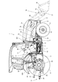
- FIGS. 1 to 5 the traveling machine body 2 of the tractor 1 is supported by a pair of left and right rear wheels 4 as well as a pair of left and right front wheels 3 as a traveling portion.
- the pair of left and right rear wheels 4 corresponds to the rear traveling unit.
- a diesel engine 5 (hereinafter simply referred to as an engine) is mounted on the front portion of the traveling machine body 2, and the tractor 1 is configured to travel forward and backward by driving the rear wheel 4 or the front wheel 3 with the engine 5.
- the engine 5 is covered with a bonnet 6.
- a cabin 7 is installed on the upper surface of the traveling machine body 2.
- Steps 10 on which the operator gets on and off are provided on the left and right outer sides of the cabin 7.
- a fuel tank 11 for supplying fuel to the engine 5 is provided below the bottom of the cabin 7.
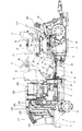
- the traveling machine body 2 includes an engine frame 14 having a front bumper 12 and a front axle case 13, and left and right machine body frames 15 detachably fixed to a rear portion of the engine frame 14.
- a front axle 16 is rotatably protruded outward from the left and right ends of the front axle case 13.
- the front wheels 3 are attached to the left and right ends of the front axle case 13 via the front axle 16.
- a transmission case 17 is connected to the rear part of the body frame 15 for appropriately changing the rotational power from the engine 5 and transmitting it to the front and rear four wheels 3, 3, 4, 4.
- Left and right rear axle cases 19 are mounted on the left and right outer surfaces of the mission case 17 so as to protrude outward.
- Left and right rear axle cases 20 are rotatably inserted in the left and right rear axle cases 19.
- the rear wheel 4 is attached to the mission case 17 via the rear axle 20.
- Upper portions of the left and right rear wheels 4 are covered with left and right rear fenders 21.
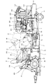
- the fuel tank 11 is arranged separately on the left and right with the traveling machine body 2 as the center. That is, the left fuel tank 11 is fixed to the outside (left side) of the left airframe frame 15 via front and rear brackets (not shown), and is disposed at a position between the left step 10 and the left airframe frame 15.
- the right fuel tank 11 is fixed to the outer side (right side) of the right body frame 15 and is disposed at a position between the right step 10 and the right body frame 15.
- a loader valve 71 for controlling supply of hydraulic oil to the hydraulic equipment of the front loader 70 is disposed outside the right fuel tank 11 (on the right side).
- the loader valve 71 is fixed to the outer side (right side) of the right body frame 15 via a valve support bracket 72 and is disposed at a position between the right step 10 and the right fuel tank 11.
- the valve support bracket 72 is configured to cover the front of the right fuel tank 11 and a part of the upper side and the right side of the right fuel tank 11, and is also connected to a front support 96 described later.
- left and right front support bases 96 that support the front side of the cabin 7 and left and right rear support bases 97 that support the rear part of the cabin 7 are provided.
- the front support 96 is bolted to the front and rear intermediate portions of the outer side surfaces of the left and right aircraft frames 15, and the front bottom of the cabin 7 is anti-vibrated on the upper surface of the front support 96 via the anti-vibration rubber body 98.
- the rear support base 97 is bolted to the middle portion of the left and right widths of the upper surfaces of the left and right rear axle cases 19 that are horizontally extended in the left-right direction, and the vibration-proof rubber body 99 is attached to the upper surface side of the rear support base 97.
- the rear bottom portion of the cabin 7 is supported by vibration isolation.
- the diesel engine 5 has a cylinder head mounted on a cylinder block having a built-in engine output shaft and a piston, and an intake manifold 203 connected to an air cleaner 221 and an exhaust manifold on the right side surface of the diesel engine 5 (cylinder head).
- An EGR device 210 that recirculates a part of the exhaust gas from 204 is arranged, and a part of the exhaust gas discharged to the exhaust manifold 204 is returned to the intake manifold 203, so that the maximum combustion temperature at the time of high load operation Is reduced, and the emission amount of NOx (nitrogen oxide) from the diesel engine 5 is reduced.
- An air cleaner 221 is disposed on the upper surface side of the diesel engine 5 (above the intake manifold 203).
- an exhaust manifold 204 connected to the tail pipe 229 is disposed on the left side surface of the diesel engine 5 (cylinder head).
- the diesel engine 5 includes a continuously regenerative exhaust gas purification device 224 (DPF) disposed on the upper surface side of the diesel engine 5 (above the exhaust manifold 204), and a tail pipe 229 is connected to the exhaust side of the exhaust gas purification device 224.
- the exhaust gas purifying device 224 removes particulate matter (PM) in the exhaust gas discharged from the engine 5 through the tail pipe 229 to the outside of the machine, and at the same time, carbon monoxide (CO) and carbonization in the exhaust gas.
- Hydrogen (HC) is configured to be reduced.
- a radiator 235 having a fan shroud 234 attached to the back side is erected on the engine frame 14 so as to be positioned on the front side of the engine 5.
- the fan shroud 234 surrounds the outer peripheral side of the cooling fan in front of the engine 5 and allows the radiator 235 and the cooling fan 206 to communicate with each other.
- an oil cooler, a fuel cooler, and the like are installed on the front side of the radiator 235.
- an engine control device (engine ECU) 271 is disposed at an upper position, and a battery 272 is disposed at a lower position.
- the engine ECU 271 receives sensor signals from the sensors of the engine 5 and controls driving of the engine 5.
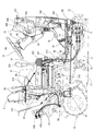
- a hydraulic lifting mechanism 22 that lifts and lowers a ground working machine (not shown) such as a rotary tiller is detachably attached.
- the ground work machine is connected to the rear portion of the transmission case 17 via a three-point link mechanism 111 including a pair of left and right lower links 23 and a top link 24.
- a PTO shaft 25 for projecting a PTO driving force to a ground working machine such as a rotary tiller is provided to project rearward.
- a front loader 70 is detachably attached to the front part of the traveling machine body 2.
- the front loader 70 includes a pair of left and right masts 73 detachably provided on the engine frame 14, a pair of left and right lift arms 74 connected to the mast 73 so as to be vertically rotatable, and a connection that connects the pair of left and right lift arms 74.
- the cylinder 80, the stand 81, and a front guard 82 that protects the front portion of the tractor 1 are configured.
- the front loader 70 works by raising and lowering the work tool 78.
- a bucket is used as the work tool 78, but other work tools can be attached.
- a pair of left and right loader mounts 83 are fixed to the outside of the left and right engine frames 14, respectively.
- a pair of left and right masts 73 are detachably attached to the pair of left and right loader mounts 83.
- the lift arm 74 is configured by welding a rear lift arm 84 attached to the mast 73 and a front lift arm 85 attached to the work tool 78. By fixing the rear lift arm 84 and the front lift arm 85 at a predetermined angle, the lift arm 74 is configured in a boomerang shape in a side view of the body.
- each rear lift arm 84 is pivotally supported at the upper end of each mast 73, and the front portion of the front loader 70 is configured to be vertically rotatable about a pair of left and right pivot shafts 86. .
- the front end portion of the mast 73 in the middle of the upper and lower portions is pivotally supported by the front end portion (rear end) of the piston rod of the arm cylinder 79.
- the arm cylinder bracket portion of the rear lift arm 84 has a longitudinal direction in the body width direction.
- the base end portion (front end) of the arm cylinder 79 is pivotally supported via a pivot shaft arranged as follows.
- the arm cylinder 79 is attached to the lower side of the front end of the rear lift arm 84.
- a pair of left and right arm cylinders 79 serve as actuators for turning the front loader 70 up and down.
- the front loader 70 is turned up and down, that is, left and right.
- the angle of the pair of lift arms 74 with respect to the mast 73 is adjusted.
- the front lift arm 85 is integrally fixed by connecting the front and rear intermediate portions thereof by a connection pipe 75 whose longitudinal direction is the body width direction.
- the front end of the front lift arm 85 is attached to the work tool 78 via the work tool bracket 77.
- the work tool bracket 77 pivotally supports the front end of the front lift arm 85. Thereby, the work tool bracket 77 and the work tool 78 can be rotated up and down with respect to the pair of left and right lift arms 74.
- Each work tool link 76 includes an arm side link member 76a and a work tool side link member 76b.
- the lower end of the arm side link member 76 a is pivotally supported by the front and rear midway part of the front lift arm 85.
- the lower end of the work tool side link member 76 b is pivotally supported on the upper part of the work tool bracket 77.
- a work tool cylinder 80 is attached to the upper side of the front end of the lift arm 74.
- the upper ends of the arm side link member 76a and the work tool side link member 76b pivotally support the tip end portion of the piston rod of the work tool cylinder 80.
- the base end portion of the work tool cylinder 80 is pivotally supported above the front end portion of the rear lift arm 84.
- the pair of left and right work tool cylinders 80 serve as actuators for pivoting the work tool bracket 77 back and forth, and the bending angle of the work tool link 76, that is, the bending angle of the work tool link 76 by the simultaneous expansion and contraction of the piston rods of the pair of left and right work tool cylinders 80.
- the angle between the arm side link member 76a and the work tool side link member 76b is adjusted, and the front-rear rotation angle of the work tool bracket 77 with respect to the lift arm 74 is adjusted.
- a flywheel 26 is connected to an output shaft (piston rod) of the engine 5 protruding rearward from the rear side surface of the engine 5.
- a main drive shaft 27 protruding backward from the flywheel 26 and a main transmission input shaft 28 protruding forward from the front side of the transmission case 17 are connected via a power transmission shaft 29 having universal shaft joints at both ends.
- a hydraulic continuously variable transmission 500, a forward / reverse switching mechanism 501, an auxiliary transmission gear mechanism 502, a two-wheel drive / four-wheel drive switching mechanism 504, a rear wheel differential gear mechanism 506, and the like are arranged inside the transmission case 17, a hydraulic continuously variable transmission 500, a forward / reverse switching mechanism 501, an auxiliary transmission gear mechanism 502, a two-wheel drive / four-wheel drive switching mechanism 504, a rear wheel differential gear mechanism 506, and the like are arranged.
- the rotational power of the engine 5 is transmitted to the main transmission input shaft 28 of the transmission case 17 via the main driving shaft 27 and the power transmission shaft 29, and is shifted by the hydraulic continuously variable transmission 500 and the auxiliary transmission gear mechanism 502.
- the power is transmitted to the left and right rear wheels 4 via the rear wheel differential gear mechanism 506.
- the shifting power from the hydraulic continuously variable transmission 500 is forward / reversely transmitted by the forward / reverse switching mechanism 501 and transmitted to the auxiliary transmission gear mechanism 502.
- the front wheel output shaft 30 projecting forward from the front lower part of the transmission case 17 is transmitted to the front wheel projecting rearward from the front axle case 13 containing the front wheel differential gear mechanism 507 via the front wheel drive shaft 31.
- the shaft 508 is connected. Shift power by the hydraulic continuously variable transmission 500 and the two-wheel drive / four-wheel drive switching mechanism 504 in the mission case 17 is for the front wheels in the front axle case 13 from the front wheel output shaft 30, the front wheel drive shaft 31, and the front wheel transmission shaft 508. It is configured to be transmitted to the left and right front wheels 3 via a differential gear mechanism 507.
- a steering column 32 is disposed in front of the control seat 8 in the cabin 7.
- the steering column 32 is erected on the rear side of a dashboard 33 disposed on the front side inside the cabin 7.
- a steering handle 9 having a substantially round shape in plan view is attached to the upper end side of the handle shaft that protrudes upward from the upper surface of the steering column 32.
- a pair of left and right brake pedals 35 for braking the traveling machine body 2 are disposed on the lower right side of the steering column 32.
- a forward / reverse switching lever 36 (reverser lever) for switching the traveling direction of the traveling machine body 2 between forward and reverse is disposed.
- a clutch pedal 37 for cutting off the output of the hydraulic continuously variable transmission 500 is disposed on the lower left side of the steering column 32.
- An erroneous operation preventing body 38 (reverser guard) extending along the forward / reverse switching lever 36 is disposed on the left side of the steering column 32 and below the forward / reverse switching lever 36.
- the erroneous operation preventing body 38 which is a contact prevention tool, to protrude outward from the forward / reverse switching lever 36, the operator is prevented from inadvertently contacting the forward / reverse switching lever 36 when getting on and off the tractor 1.
- An operation display panel 39 incorporating a liquid crystal panel is provided on the upper rear side of the dashboard 33.
- a parking brake lever 43 for maintaining the left and right rear wheels 4 in a braking state and an accelerator lever 48 for setting and maintaining the rotational speed of the engine 5 are arranged on the right side of the steering column 32. That is, the accelerator lever 48 is inserted at a position on the right side of the steering column 32 in the dashboard 33, and the base end of the accelerator lever 48 is fixed so as to be rotatable in the dashboard 33. A potentiometer (variable resistor) type accelerator lever sensor 48 a for detecting the vertical tilt of the accelerator lever 48 is provided in the dashboard 33.
- the brake lever 43 is disposed at a position on the lower side of the accelerator lever 48, and the base end side is provided in the steering column 32.
- the main shift pedal 41 for controlling the rotational speed of the engine 5 or the vehicle speed is disposed on the right side of the steering column 32 in the floor plate 40 in front of the control seat 8 in the cabin 7. Note that substantially the entire top surface of the floor plate 40 is formed as a flat surface.
- a potentiometer (variable resistor) type pedal sensor 41 a for detecting the vertical tilt of the main transmission pedal 41 is fixed below the floor plate 40.
- the left and right side columns 42 are arranged on both the left and right sides of the control seat 8.
- the auxiliary transmission lever 44 that switches the output range of the traveling auxiliary transmission gear mechanism 503 in the mission case 17 and the two-wheel drive and the four-wheel drive of the front and rear wheels 3 and 4 are switched.
- a four-wheel drive lever 45 and a PTO speed change lever 46 for switching the driving speed of the PTO shaft 25 are arranged.
- a differential lock pedal 47 for turning on and off the differential drive of the left and right rear wheels 4 is disposed below the control seat 8.
- the working part position lever 50 which changes and adjusts the height position of ground working machines, such as a rotary tiller, is arrange
- the rotation speed / vehicle speed setting dial 53 for presetting the maximum rotation speed of the engine 5 or the maximum traveling speed of the traveling machine body 2 and the value set by the rotation speed / vehicle speed setting dial 53 are set to the maximum rotation speed of the engine 5 or the traveling machine body 2.
- a plurality of hydraulic operation levers 56 (SCV levers) for switching the hydraulic external take-off valve 430 to be operated are arranged.
- the hydraulic external take-off valve 430 is for supplying and controlling hydraulic oil to hydraulic equipment of a work machine such as a rotary tiller or a component caster that is retrofitted to the tractor 1.
- two hydraulic operation levers 56 are arranged in accordance with the number of hydraulic external take-out valves (two stations).
- the dashboard 33 includes a wiper drive mechanism 422 behind the front window glass 350.
- the wiper drive mechanism 422 includes a drive motor that generates rotational power to the wiper 421 that is pivotally supported by the front window glass 321 and a gear mechanism that transmits rotational power of the drive motor to the wiper 421.
- a meter panel 906 is fixed to the dashboard 33, and a meter controller (meter ECU) 904 electrically connected to the meter panel 906 is integrally formed with the meter panel 906, and the meter controller 904 is provided in the dashboard 33. Are buried.
- the meter panel 906 is disposed in a state where the panel surface is inclined slightly upward from the rear so as to face the operator seated on the control seat 8 at a position on the lower front side of the control handle 9.
- a plurality of switch members 907 such as parking switches are disposed at the outer peripheral portion position of the meter panel 906 on the dashboard 33, for example.
- the key switch 61 is a rotary switch that can be rotated with a predetermined key inserted into the keyhole, and is attached to the right side of the steering handle 9 on the dashboard 33.
- the meter panel 906 has a liquid crystal panel 908 that displays characters in the center display area as a driving operation display device, and an engine tachometer 909 that indicates the rotational speed of the engine 5 with a pointer on the outer periphery of the liquid crystal panel 908. Provided.
- the meter panel 906 has a fuel meter 910 that indicates the remaining amount of fuel as a pointer on the left side of the engine tachometer 909, and a water temperature meter 911 that indicates the cooling water temperature of the engine 5 as a pointer on the right side of the engine tachometer 909. It is arranged.
- the meter panel 906 has a plurality of display lamps 912 and 913 formed by LEDs or the like in the display area on the left and right outside of the engine tachometer 909 (outside the center display area).
- the display lamps 912 and 913 arranged on the left and right sides of the engine tachometer 909 act as warning lights and indicator lights.
- one of the display lamps 912 is assigned to a regeneration lamp that indicates the regeneration processing state of the exhaust gas purification device 224, and the display lamp 913 has anti-stall control, accelerator-linked control, and auto-cruise control. Assigned to the indicator lamp indicating the ON / OFF state.
- the steering column 32 is erected in a state of being embedded in the back side of the dashboard 33.
- a vertically long handle shaft 921 is supported in the steering column 32.
- the upper end side of the handle shaft 921 protrudes upward from the upper surface of the steering column 32.
- a steering handle 9 having a substantially round shape in plan view is attached to the upper end side of the handle shaft 921.
- the front end side of the vertically long steering shaft 740 is connected to the lower end side of the handle shaft 921 through a universal joint.
- a power steering hydraulic mechanism 621 supported on the lower side of a board support plate (air cut plate) 901 is connected to the base end side of the steering shaft 740 via a universal joint.
- a DPF regeneration switch 64 for executing regeneration control of the exhaust gas purifying device 224 is provided on the upper surface of the steering column 32 at the base of the steering handle 9.
- the DPF regeneration switch 64 is disposed in the operator's field of view when in the straight working posture. Therefore, the position and lighting display state of the DPF regeneration switch 64 can be easily visually recognized by a seated operator without the DPF regeneration switch 64 being hidden by the steering handle 9 or the like.
- a plurality of switches 65 and 66 such as a travel switch and a one-touch automatic switch are disposed on the upper surface of the steering column 32 at positions symmetrical with respect to the handle shaft 921 of the steering handle 9. Therefore, a seated operator can easily confirm the positions of the travel switch and the one-touch automatic switch by visually recognizing the switches 65 and 66 arranged on the upper surface of the steering column 32, so that erroneous operations can be reduced.
- a DPF regeneration switch 64 and switches 65 and 66 such as a travel switch and a one-touch automatic switch are provided on the upper surface of the steering column 32 at the base of the steering handle 9.
- a DPF regeneration switch 64 is provided on the upper surface of the steering column 32 above the brake pedal 35.
- switches 65 and 66 using a travel switch or a one-touch automatic switch are installed with a spoke of the steering handle 9 arranged on the front and rear center line of the traveling machine body 2 interposed therebetween.
- the switch 65 disposed on the left side is a travel switch (auto cruise operation switch)
- the switch 66 disposed on the right side is a one-touch automatic switch (accelerator-linked control switch, display switch, and anti-switch). Stall control switch).
- a seat support plate 315 having an L-shaped plate in side view is erected from the floor plate 40 in the cabin 7, and the control seat 8 is disposed on the seat support plate 315.
- a rail member 316 for sliding the control seat 8 back and forth is fixed to the upper surface of the seat support plate 315, and the bottom of the control seat 8 is locked to the rail member 316.
- the rear cover plate 314 is connected to the rear edge of the seat support plate 315 so that the rear cover plate 314 is erected so as to cover the rear side of the control seat 8.
- a support plate 317 is erected from the right edge behind the seat support plate 315, and a lever fixing bracket 318 is fixed to the upper edge of the support plate 317.
- the lever fixing bracket 318 is connected to the right side column 42 so as to be installed inside the right side column 42.
- a hydraulic operation lever 56 is mounted and fixed on the upper surface of the lever fixing bracket 318, and a grip (gripping portion) of the hydraulic operation lever 56 protrudes outside the right side column 42.
- the hydraulic operation lever 56 is connected to the hydraulic external take-off valve 430 through a push-pull wire 57 fixed to the lever fixing bracket 318.
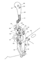
- a lever fixing bracket 319 is fixed to the front surface on the right side of the seat support plate 315, and a loader lever 51 is swingably supported by the lever fixing bracket 319.
- the lever fixing bracket 319 is covered with the right side column 42, and the grip (gripping part) 320 of the loader lever 51 protrudes from the upper surface of the right side column 42.
- the loader lever 51 has a crank shape, and the grip 320 is disposed on the control seat 8 side. That is, the loader lever 51 is fixed at the front position of the right side column 42, and the grip 320 is disposed at the right front of the control seat 8 where the operator can easily operate the operability of the front loader 70. To do.
- the loader lever 51 is connected to the loader valve 71 via push-pull wires 58 and 59 fixed to the lever fixing bracket 319.
- a lock fitting 321 that locks the tilt of the loader lever 51 is provided so that it can be inserted into and removed from the lever fixing bracket 319.
- the lock fitting 321 is formed in a U-shape, and the operator can easily hold the lock fitting 321 by protruding the bent portion of the lock fitting 321 from the front surface of the right side column 42. Therefore, the operator can easily insert and remove the lock fitting 321 according to whether or not the front loader 70 is operated. Then, by inserting the lock fitting 321 into the lever fixing bracket 319, the tilt of the loader lever 51 can be prohibited (locked), so that an inadvertent operation on the front loader 70 can be prevented beforehand.
- the loader valve 71 is fixed to the body frame 15 via a valve support bracket 72 having an L shape in plan view.
- the loader valve 71 is disposed outside the fuel tank 11 by arranging the valve support bracket 72 so as to bypass the front of the fuel tank 11.
- the valve support bracket 72 can support the valve support bracket 72 with high rigidity by being connected to the front support base 96 fixed to the body frame 15.
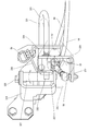
- the loader lever 51 has a base end side fixed to the middle part of the right and left tilting link 322 and a tip end side fitted into the grip 320.
- the left / right tilting link 322 is formed of a V-shaped metal plate that is bifurcated from the connection portion with the base end of the loader lever 51, and one of the bifurcated portions is bent rearward to have an L shape in plan view. ing.
- the left and right tilt link 322 is provided with a through hole 323 into which one end of the lock fitting 321 is inserted and removed at the other end positioned on the lower side of the front surface while the tip end of the push-pull wire 58 is connected to one end positioned rearward. .
- the lock fitting 321 is inserted in the guide tube 324 fixed to the lever fixing bracket 319 at the other end, and is slid along the extending direction of the guide tube 324. That is, by inserting one end of the lock fitting 321 into the through hole 323 of the left / right tilt link 322, the tilting operation of the loader lever 51 is locked, and one end of the lock fitting 321 is extracted from the through hole 323 of the left / right tilt link 322. As a result, the lock of the tilting operation of the loader lever 51 is released.
- a shaft body 325 extending rearward is provided at a bent portion above the through hole 323 in the link 322 for tilting left and right (a bent portion in the vicinity of a connecting portion with the base end of the loader lever 51). Then, by passing the shaft body 325 through the front / rear tilt link 326, the left / right tilt link 322 is pivotally supported by the front / rear tilt link 326 and can swing in the left / right direction. That is, in accordance with the left / right tilting operation of the loader lever 51, the left / right tilting link 322 swings in the left / right direction and moves the tip of the push-pull wire 58 up and down.
- the shaft 325 is inserted into one end of the forward / backward tilting link 326, while the other end side is bent forward to connect the tip of the push-pull wire 59.
- a cylindrical boss 327 extending in the left-right direction is fixed to one end of the forward / backward tilting link 326, and a shaft body 328 fixed to the lever fixing bracket 319 is inserted into the boss 327.
- the front / rear tilting link 326 is pivotally supported by the lever fixing bracket 319 and can swing in the front / rear direction. That is, in accordance with the forward / backward tilting operation of the loader lever 51, the left / right tilting link 322 swings in the left / right direction, and the tip of the push-pull wire 59 is moved up and down.
- the connecting portion with the push-pull wire 58 in the right-and-left tilting link 322 is positioned on the extension line of the axis of the shaft body 325. Therefore, when the loader lever 51 is tilted in the front-rear direction, the left-right tilt link 322 swings together with the front-rear tilt link 326. At this time, since the tip end position of the push-pull wire 58 is a pivotal fulcrum position with respect to the forward / backward tilting link 326, the forward / backward tilting operation of the loader lever 51 does not act on the push-pull wire 58.
- the lever fixing bracket 319 constitutes a restriction hole 331 for restricting the tilting range of the loader lever 51 by connecting both ends of the two U-shaped metal fittings 329 and 330 above the lever fixing bracket 319.
- the restriction hole 331 is configured such that the left-right width and the front-rear width are wide at the neutral position of the loader lever 51.
- the restriction hole 331 is formed so that the opening portion is narrowed symmetrically toward the front, while the right side is narrowed toward the rear.
- the arm valve (not shown) in the loader valve 71 acts when the push-pull wire 59 is pushed and pulled in response to the forward / backward tilting operation of the loader lever 51.
- the arm cylinder 79 extends and retracts to move the left and right lift arms 74 up and down, and as a result, the work tool 78 moves up and down.
- the push-pull wire 58 pushes and pulls in response to the left / right tilting operation of the loader lever 51, whereby the work implement valve (not shown) in the loader valve 71 acts.
- the work tool cylinder 80 is extended and retracted to perform a tilting operation for turning the work tool 78 upward to crush the soil, or to perform a dumping operation for rotating the work tool 78 downward to drop the soil or the like. Will do.
- the engine tilt switch 301 is provided on the front surface of the grip 320, and the valve operation switch 302 and the mode changeover switch 303 are provided on the left side surface of the grip 320. That is, since the grip 320 is gripped by the operator's right hand, the engine tilt switch 301 is disposed at a position where it can be operated with an index finger or the like, and the valve operation switch 302 and the mode switch 303 are disposed at a position where the operator can operate with the thumb. Is done. Therefore, the operator can easily operate the switches 301 to 303 while holding the loader lever 51 during the loader work by the front loader 70.
- the engine tilt switch 301 is used, for example, when a high load is applied during execution of a tilting operation that crushes soil or the like by the front loader 70 or a dozer operation that scratches the ground. As shown in FIG. 19, by operating the engine tilt switch 301, the engine speed of the engine 5 is increased, while the gear ratio of the hydraulic continuously variable transmission 500 is decreased to keep the vehicle speed of the tractor 1 constant. Execute control.
- the engine tilt control is performed when the first speed and the second speed are designated among the sub speeds that can be designated up to the third speed by the sub speed change lever 44, and the mode change control by the mode change switch 303 is not executed. This is executed while the engine tilt switch 301 is pressed.
- the operator determines that the loader lever 51 is operating at the same time based on hearing and vision during the loader operation by the front loader 70, and at the same time operates the loader lever 51.
- the engine tilt control is simply executed with (right hand in this embodiment). Therefore, even when the work load is not satisfied, the hydraulic lift for the arm cylinder 79 and the work tool cylinder 80 can be increased instantaneously according to the operator's judgment, so that the complexity of operating the work machine such as the front loader 70 can be reduced. Not only can this be eliminated, but the load on the work machine can be reduced.
- the valve operation switch 302 is a hydraulic cylinder other than the arm cylinder 79 and the work tool cylinder 80. It is used when the work tool 78 is provided. By operating the valve operation switch 302, the bale grab cylinder in the bale grab serving as the work tool 78 expands and contracts, and the pasture roll can be held or released.
- the arm cylinder 79 is operated by the forward / backward tilting operation of the loader lever 51 to move the work tool 78 up and down
- the work tool cylinder 80 is operated by the left / right tilting operation of the loader lever 51 to operate the work tool 78.
- the bale grab is tilted up and down
- the valve operation switch 302 of the loader lever 51 is further operated to operate the bale grab cylinder so that the bale grab serving as the work tool 78 is opened and closed.
- the mode selector switch 303 is used when switching between the maximum rotation speed and the maximum speed set in advance for a plurality of modes. Although the present embodiment will be described as the case of the two modes of the first mode and the second mode, it is possible that settings of three or more modes can be executed.
- the maximum rotation speed and the maximum vehicle speed in the first and second modes are set by operating the rotation speed / vehicle speed setting dial 53 and the rotation speed / vehicle speed selection switch 54, which are rotation speed / vehicle speed setting operation tools.
- the rotational speed of the engine 5 and the vehicle speed of the tractor 1 at the maximum positions of the accelerator lever 48 and the main transmission pedal 41 are set as the maximum rotational speed and the maximum vehicle speed set in the first and second modes, respectively.
- the mode switching switch 303 By operating the mode switching switch 303, switching between the first mode and the second mode is executed, and the maximum rotation speed and the maximum vehicle speed in the first and second modes are switched according to the operation to the mode switching switch 303. .
- the maximum rotation speed R2 and the maximum vehicle speed V2 in the second mode are set to be smaller than the maximum rotation speed R1 and the maximum vehicle speed V1 in the first mode.
- the second mode is operated by operating the mode switch 303.
- the tractor 1 is moved at a low speed, so that the object to be transported can be prevented from dropping.
- the mode selector switch 303 is operated to switch to the first mode, so that the tractor 1 is moved at a high speed, so that the travel time from the carry-out destination to the carry-in source is shortened. It is possible to improve work efficiency.
- the mode changeover switch 303 By arranging the mode changeover switch 303 on the loader lever 51, the operator operates the loader lever 51 based on the presence or absence of the object to be transported during the transporting operation by the front loader 70 (in this embodiment, the right hand). ) To easily switch the moving speed of the tractor 1. Therefore, when the transport object is transported by the front loader 70, the transport object can be prevented from falling, and the travel time can be shortened when the transport object is moved after the transport is completed, so that work efficiency can be improved.
- the mode switching operation by the mode switching switch 303 is prohibited when the engine tilt switch 301 or the engine tilt control or the auto cruise control by the switch 65 (running control for traveling while maintaining the specified vehicle speed) is performed. Is done.
- the accelerator interlock control when executed by the switch 66, the vehicle speed when only the main shift pedal 41 is at the maximum position is set as the maximum vehicle speed set for each mode.
- the accelerator interlocking control when the accelerator interlocking control is not executed, the vehicle speed when the main transmission pedal 41 and the accelerator lever 48 are at the maximum positions is set as the maximum vehicle speed set for each mode.
- the accelerator interlocking control when the accelerator interlocking control is executed, the vehicle speed of the tractor 1 is changed according to the depression amount of the main shift pedal 41, and the engine 5 is changed from the minimum rotational speed set by the accelerator lever 48. The number of revolutions changes.
- the tractor 1 is maintained in a state where the rotational speed of the engine 5 is kept constant at the minimum rotational speed set by the accelerator lever 48 according to the depression amount of the main shift pedal 41. Change the vehicle speed.
- a work vehicle (tractor) 1 is configured to transmit power from an engine 5 mounted on a traveling machine body 2 to a traveling unit 3, 4 or a working unit 70 by changing a speed at a mission unit 17. ing.
- a work vehicle (tractor) 1 includes a mode changeover switch 303 for switching the maximum vehicle speed by the traveling units 3 and 4 set for each of a plurality of modes or the maximum rotation speed of the engine 5, and a work unit operation lever (for operating the work unit 70).
- Loader lever) 51, and a mode selector switch 303 is provided on the working unit operation lever 51. Therefore, the working unit operating lever 51 can switch the maximum vehicle speed of the traveling units 3 and 4 or the maximum number of revolutions of the engine 5 in accordance with the operating state of the working unit 70.
- a work unit operation lever 51 is arranged on the traveling unit 2 on the outer side of the control seat 8 in the control unit (cabin) 7, and the grip 320 of the work unit operation lever 51 is attached to the control seat.
- the mode changeover switch 303 is arranged on the grip 320.
- a mode changeover switch 303 is disposed on the side surface of the grip 320 on the control seat 8 side.
- the mode changeover switch 303 By disposing the mode changeover switch 303 on the grip 320 of the working unit operation lever 51, the mode changeover switch 303 can be operated at a position where the operator can easily hold it, so that the operability can be further improved. Further, by providing the mode changeover switch 303 on the side surface of the grip 320 on the side of the control seat 8, the operator can easily operate the mode changeover switch 303 with the thumb of the hand holding the grip 320, thereby reducing the complexity of the operation. Can be resolved.
- the engine operation switch 51 is provided with an engine tilt switch 301 for executing engine tilt control for increasing the rotational speed of the engine 5 while maintaining the vehicle speed of the traveling units 3 and 4 constant. Further, when the engine tilt control is being executed, the operation on the mode switch 303 is invalidated.
- the engine tilt switch 301 for executing the engine tilt control is provided on the working unit operation lever 51, the operator changes the engine 5 rotation speed according to the load applied to the working unit 70, while the traveling units 3 and 4 The vehicle speed can be kept constant. Therefore, since the change of the vehicle speed of the traveling units 3 and 4 can be suppressed by the load applied to the working unit 70, it is possible to suppress the decrease in working efficiency using the working unit 70. Also, by disabling the operation of the mode selector switch 303 during engine tilt control, the engine speed increased during engine tilt control prevents the maximum vehicle speed and maximum engine speed after switching from becoming abnormal values. It is possible to prevent sudden accidents.
- a shift pedal (main shift pedal) 41 that adjusts the vehicle speed by the traveling units 3, 4 or the rotation speed of the engine 5, and a forward / reverse switching lever 36 that designates forward / backward traveling by the traveling units 3, 4.
- the mission unit 17 includes a hydraulic continuously variable transmission 500 that shifts the power from the engine 5 and a forward / reverse switching mechanism 501 that reverses the speed of the variable speed power from the hydraulic continuously variable transmission 500. Then, the gear ratio by the hydraulic continuously variable transmission 500 is changed by the shift pedal 41, and the switching by the forward / reverse switching mechanism 501 may be performed by the forward / reverse switching lever 36.
Landscapes
- Engineering & Computer Science (AREA)
- Chemical & Material Sciences (AREA)
- Combustion & Propulsion (AREA)
- Transportation (AREA)
- Mechanical Engineering (AREA)
- Physics & Mathematics (AREA)
- General Physics & Mathematics (AREA)
- Automation & Control Theory (AREA)
- Arrangement Or Mounting Of Control Devices For Change-Speed Gearing (AREA)
- Mechanical Control Devices (AREA)
- Control Of Transmission Device (AREA)
Abstract
The work vehicle (1) of the present application is configured so that motive force from an engine (5) installed in a travel machine body (2) is transmitted to traveling parts (3, 4) and a work part (70) at a changed speed by a transmission part (17). The work vehicle (1) comprises: a mode-switching switch (303) that switches the maximum vehicle speed for the traveling parts (3, 4) or the maximum speed of the engine (5) set for each of a plurality of modes; and a work part operation lever (51) that operates the work part (70). The mode-switching switch (303) is provided to the work part operation lever (51).
Description
本願発明は、耕耘作業機または播種作業機などの対地作業機を牽引する農作業用のトラクタまたは土木作業用のホイルローダなどの作業車両に関するものである。
The present invention relates to a work vehicle such as a tractor for agricultural work or a wheel loader for civil engineering work that pulls a ground work machine such as a tillage work machine or a sowing work machine.
トラクタやホイルローダ等の作業車両においては、走行機体を操向操作するための操縦ハンドルや、走行機体の走行状態を設定調節するための複数のレバー部材等が、操作性を考慮して操縦座席の周囲に配置されている。例えば、農作業用のトラクタでは、複数のレバー部材として、主変速レバー、副変速レバー、前後進切換レバー、並びにPTO変速レバー等を有している(特許文献1参照)。主変速レバーは走行機体の車速を変更操作するものであり、副変速レバーは変速機の変速出力を所定範囲に設定保持するものである。前後進切換レバーは走行機体の進行方向を前進と後進とに切換操作するものであり、PTO変速レバーは作業機への出力(PTO駆動力)を変速操作するものである。また、トラクタの先端にローダを装着した場合には、ローダ操作用のレバー(ジョイスティックレバー)が設けられる。
In a work vehicle such as a tractor or a wheel loader, a steering handle for steering the traveling body and a plurality of lever members for setting and adjusting the traveling state of the traveling body are provided for the control seat in consideration of operability. It is arranged around. For example, a farm tractor has a main transmission lever, a sub transmission lever, a forward / reverse switching lever, a PTO transmission lever, and the like as a plurality of lever members (see Patent Document 1). The main transmission lever is used to change the vehicle speed of the traveling machine body, and the auxiliary transmission lever is used to set and hold the transmission output of the transmission within a predetermined range. The forward / reverse switching lever switches the traveling direction of the traveling machine body between forward and backward, and the PTO shift lever shifts the output (PTO driving force) to the work machine. When a loader is attached to the tip of the tractor, a loader operating lever (joystick lever) is provided.
ローダなどの作業部を装着したトラクタにおいては、作業部の操作をしながら走行部の操作をすることにより、作業効率の向上を図っている。しかしながら、従来のトラクタにおいては、作業部用の操作具を作業部とともにトラクタに後付けとなるため、オペレータが所望する操作が達成できず、作業効率向上の妨げとなっていた。
In a tractor equipped with a work unit such as a loader, the operation efficiency is improved by operating the traveling unit while operating the work unit. However, in the conventional tractor, since the operation tool for the working unit is retrofitted to the tractor together with the working unit, the operation desired by the operator cannot be achieved, which hinders improvement in working efficiency.
本願発明は、上記のような現状を検討して改善を施したトラクタを提供することを技術的課題としている。
The present invention has a technical problem to provide an improved tractor by examining the current situation as described above.
本願発明の作業車両は、走行機体に搭載されたエンジンからの動力を、ミッション部にて変速して走行部や作業部に伝達するように構成されている作業車両であって、複数のモード毎に設定された前記走行部による最高車速又は前記エンジンの最高回転数を切り換えるモード切換スイッチと、前記作業部を操作する作業部操作レバーとを備え、前記作業部操作レバーにモード切換スイッチを設けたものである。
The work vehicle of the present invention is a work vehicle configured to transmit power from an engine mounted on a traveling machine body to a traveling unit and a working unit by changing a speed in a mission unit, and each of the plurality of modes. A mode switching switch for switching the maximum vehicle speed or the maximum engine speed by the traveling unit set to, and a working unit operating lever for operating the working unit, and the mode switching switch is provided in the working unit operating lever. Is.
このような作業車両において、前記走行機体上の操縦部において、操縦座席の外側前方に前記作業部操作レバーが配置されるとともに、前記作業部操作レバーのグリップを前記操縦座席寄りに配置させ、前記グリップに前記モード切換スイッチが配置されるものとしてもよい。
In such a work vehicle, in the control unit on the traveling machine body, the working unit operation lever is disposed in front of the outer side of the control seat, and the grip of the working unit operation lever is disposed closer to the control seat, The mode selector switch may be disposed on the grip.
また、前記グリップの前記操縦座席側となる側面に前記モード切換スイッチが配置されるものとしてもよい。
Further, the mode change switch may be arranged on the side surface of the grip on the side of the control seat.
上記作業車両において、前記走行部の車速を一定に維持しながら前記エンジンの回転数を上昇させるエンジンあおり制御を実行させるエンジンあおりスイッチを、前記作業部操作レバーに設けたものとしてもよい。
In the work vehicle, an engine tilt switch for executing engine tilt control for increasing the engine speed while maintaining the vehicle speed of the traveling unit constant may be provided on the work unit operation lever.
更に、前記エンジンあおり制御が実行されている際、前記モード切換スイッチへの操作が無効とされるものとしてもよい。
Furthermore, when the engine tilt control is being executed, the operation to the mode switch may be invalidated.
また、上記作業車両において、前記走行部による車速又は前記エンジンの回転数を調整する変速ペダルと、前記走行部による前後進を指定する前後進切換レバーとを備えており、前記ミッション部が、前記エンジンからの動力を変速する油圧無段変速機と、前記油圧無段変速機からの変速動力を正反転する前後進切換機構とを具備し、前記変速ペダルにより前記油圧無段変速機による変速比が変更される一方、前記前後進切換レバーにより前記前後進切換機構による切換が実行されるものとしてもよい。
The work vehicle further includes a shift pedal that adjusts a vehicle speed by the traveling unit or an engine speed, and a forward / reverse switching lever that specifies forward / backward traveling by the traveling unit, and the mission unit includes the transmission unit A hydraulic continuously variable transmission for shifting the power from the engine; and a forward / reverse switching mechanism for forward and reverse shifting of the shift power from the hydraulic continuously variable transmission, and a transmission gear ratio by the hydraulic continuously variable transmission by the shift pedal. On the other hand, switching by the forward / reverse switching mechanism may be executed by the forward / reverse switching lever.
本願発明によれば、作業部操作レバーにモード切換スイッチを設けた構成としているため、作業部操作レバーにより作業部の動作状態に合わせて、走行部の最高車速又はエンジンの最高回転数を切り換えることができ、一つの操作具で作業部と走行部を同時に操作できるため、操作性の向上を図れる。また、作業部にかかる負荷に応じて、走行部の最高車速又はエンジンの最高回転数を切り換えることにより、作業ミスを抑制できるだけでなく、非作業時の移動時間を短縮できるとともに、非作業時の燃費を向上できる。
According to the present invention, since the mode selector switch is provided on the working unit operation lever, the maximum vehicle speed of the traveling unit or the maximum engine speed is switched by the working unit operation lever in accordance with the operating state of the working unit. Since the working unit and the traveling unit can be operated simultaneously with a single operating tool, the operability can be improved. In addition, by switching the maximum vehicle speed of the traveling unit or the maximum engine speed according to the load on the working unit, not only can work errors be suppressed, but the traveling time during non-working can be shortened, and Fuel consumption can be improved.
本願発明によれば、作業部操作レバーのグリップにモード切換スイッチを配置することにより、オペレータが把持しやすい位置でモード切換スイッチを操作できるため、操作性の更なる向上を図れる。また、グリップの操縦座席側となる側面にモード切換スイッチを設けることにより、オペレータはグリップを把持している手の親指で容易にモード切換スイッチを操作でき、操作の煩雑さを解消できる。
According to the present invention, by disposing the mode change switch on the grip of the working unit operation lever, the mode change switch can be operated at a position where the operator can easily hold it, so that the operability can be further improved. Further, by providing the mode change switch on the side of the grip on the side of the control seat, the operator can easily operate the mode change switch with the thumb of the hand holding the grip, thereby eliminating the complexity of the operation.
本願発明によれば、エンジンあおり制御を実行するためのエンジンおありスイッチを作業部操作レバーに設けたため、オペレータは、作業部にかかる負荷に応じてエンジン回転数を変化させる一方で、走行部による車速を一定に維持できる。従って、作業部にかかる負荷により走行部の車速の変化を抑制できることから、作業部を使用した作業効率の低下をも抑制できる。また、エンジンあおり制御の実行時にモード切換スイッチの操作を無効とすることで、エンジンあおり制御時に上昇したエンジン回転数により、切換後の最高車速や最高エンジン回転数が異常値となることを防止でき、突発的な事故などを未然に防止できる。
According to the present invention, since the engine operation switch for executing the engine tilt control is provided on the working unit operation lever, the operator changes the engine speed according to the load applied to the working unit, while the traveling unit The vehicle speed can be kept constant. Therefore, since the change of the vehicle speed of a traveling part can be suppressed by the load concerning a working part, the fall of the working efficiency using a working part can also be suppressed. Also, by disabling the operation of the mode selector switch during engine tilt control, it is possible to prevent the maximum vehicle speed after switching and the maximum engine speed from becoming abnormal values due to the engine speed increased during engine tilt control. Sudden accidents can be prevented.
以下に、本願発明を具体化した実施形態について、農作業用トラクタを図面に基づき説明する。図1~図5に示す如く、トラクタ1の走行機体2は、走行部としての左右一対の前車輪3と同じく左右一対の後車輪4とで支持されている。左右一対の後車輪4が後方走行部に相当するものである。走行機体2の前部にディーゼルエンジン5(以下、単にエンジンという)を搭載し、後車輪4または前車輪3をエンジン5で駆動することによって、トラクタ1が前後進走行するように構成されている。エンジン5はボンネット6にて覆われている。走行機体2の上面にはキャビン7が設置される。該キャビン7の内部には、操縦座席8と、前車輪3を操向操作する操縦ハンドル9とが配置されている。キャビン7の左右外側には、オペレータが乗降するステップ10が設けられている。エンジン5に燃料を供給する燃料タンク11がキャビン7底部の下側に設けられている。
Hereinafter, an embodiment of the present invention will be described with reference to the drawings of a farm tractor. As shown in FIGS. 1 to 5, the traveling machine body 2 of the tractor 1 is supported by a pair of left and right rear wheels 4 as well as a pair of left and right front wheels 3 as a traveling portion. The pair of left and right rear wheels 4 corresponds to the rear traveling unit. A diesel engine 5 (hereinafter simply referred to as an engine) is mounted on the front portion of the traveling machine body 2, and the tractor 1 is configured to travel forward and backward by driving the rear wheel 4 or the front wheel 3 with the engine 5. . The engine 5 is covered with a bonnet 6. A cabin 7 is installed on the upper surface of the traveling machine body 2. Inside the cabin 7, a steering seat 8 and a steering handle 9 for steering the front wheel 3 are arranged. Steps 10 on which the operator gets on and off are provided on the left and right outer sides of the cabin 7. A fuel tank 11 for supplying fuel to the engine 5 is provided below the bottom of the cabin 7.
走行機体2は、前バンパー12及び前車軸ケース13を有するエンジンフレーム14と、エンジンフレーム14の後部に着脱自在に固定した左右の機体フレーム15とにより構成されている。前車軸ケース13の左右両端側から外向きに、前車軸16を回転可能に突出させている。前車軸ケース13の左右両端側に前車軸16を介して前車輪3を取り付けている。機体フレーム15の後部には、エンジン5からの回転動力を適宜変速して前後四輪3,3,4,4に伝達するためのミッションケース17を連結している。ミッションケース17の左右外側面には、左右の後車軸ケース19を外向きに突出するように装着している。左右の後車軸ケース19には左右の後車軸20を回転可能に内挿している。ミッションケース17に後車軸20を介して後車輪4を取り付けている。左右の後車輪4の上方は左右のリヤフェンダー21によって覆われている。
The traveling machine body 2 includes an engine frame 14 having a front bumper 12 and a front axle case 13, and left and right machine body frames 15 detachably fixed to a rear portion of the engine frame 14. A front axle 16 is rotatably protruded outward from the left and right ends of the front axle case 13. The front wheels 3 are attached to the left and right ends of the front axle case 13 via the front axle 16. A transmission case 17 is connected to the rear part of the body frame 15 for appropriately changing the rotational power from the engine 5 and transmitting it to the front and rear four wheels 3, 3, 4, 4. Left and right rear axle cases 19 are mounted on the left and right outer surfaces of the mission case 17 so as to protrude outward. Left and right rear axle cases 20 are rotatably inserted in the left and right rear axle cases 19. The rear wheel 4 is attached to the mission case 17 via the rear axle 20. Upper portions of the left and right rear wheels 4 are covered with left and right rear fenders 21.
走行機体2を中心として燃料タンク11が左右に分かれて配置されている。すなわち、左側燃料タンク11が、前後のブラケット(図示省略)を介して左機体フレーム15外側(左側)に固定されて、左ステップ10と左機体フレーム15の間となる位置に配置されている。右側燃料タンク11が、右機体フレーム15外側(右側)に固定されて、右ステップ10と右機体フレーム15の間となる位置に配置されている。また、右側燃料タンク11の外側(右側)には、フロントローダ70の油圧機器に作動油を供給制御するためのローダバルブ71が配置されている。ローダバルブ71は、バルブ支持ブラケット72を介して、右機体フレーム15外側(右側)に固定されて、右ステップ10と右側燃料タンク11の間となる位置に配置されている。バルブ支持ブラケット72は、右側燃料タンク11の前方と、右側燃料タンク11の上方及び右側方の一部とを覆うように構成されており、後述の前部支持台96とも連結している。
The fuel tank 11 is arranged separately on the left and right with the traveling machine body 2 as the center. That is, the left fuel tank 11 is fixed to the outside (left side) of the left airframe frame 15 via front and rear brackets (not shown), and is disposed at a position between the left step 10 and the left airframe frame 15. The right fuel tank 11 is fixed to the outer side (right side) of the right body frame 15 and is disposed at a position between the right step 10 and the right body frame 15. A loader valve 71 for controlling supply of hydraulic oil to the hydraulic equipment of the front loader 70 is disposed outside the right fuel tank 11 (on the right side). The loader valve 71 is fixed to the outer side (right side) of the right body frame 15 via a valve support bracket 72 and is disposed at a position between the right step 10 and the right fuel tank 11. The valve support bracket 72 is configured to cover the front of the right fuel tank 11 and a part of the upper side and the right side of the right fuel tank 11, and is also connected to a front support 96 described later.
さらに、キャビン7の前側を支持する左右の前部支持台96と、キャビン7の後部を支持する左右の後部支持台97を備える。左右の機体フレーム15の機外側面のうち前後中間部に前部支持台96をボルト締結させ、前部支持台96の上面側に防振ゴム体98を介してキャビン7の前側底部を防振支持すると共に、左右方向に水平に延設させる左右の後車軸ケース19の上面のうち左右幅中間部に後部支持台97をボルト締結させ、後部支持台97の上面側に防振ゴム体99を介してキャビン7の後側底部を防振支持している。
Furthermore, left and right front support bases 96 that support the front side of the cabin 7 and left and right rear support bases 97 that support the rear part of the cabin 7 are provided. The front support 96 is bolted to the front and rear intermediate portions of the outer side surfaces of the left and right aircraft frames 15, and the front bottom of the cabin 7 is anti-vibrated on the upper surface of the front support 96 via the anti-vibration rubber body 98. The rear support base 97 is bolted to the middle portion of the left and right widths of the upper surfaces of the left and right rear axle cases 19 that are horizontally extended in the left-right direction, and the vibration-proof rubber body 99 is attached to the upper surface side of the rear support base 97. The rear bottom portion of the cabin 7 is supported by vibration isolation.
ディーゼルエンジン5は、エンジン出力軸とピストンとを内蔵するシリンダブロック上にシリンダヘッドを搭載しており、ディーゼルエンジン5(シリンダヘッド)右側面には、エアクリーナ221に接続させる吸気マニホールド203と、排気マニホールド204からの排気ガスの一部を再循環させるEGR装置210を配置し、排気マニホールド204に排出された排気ガスの一部が、吸気マニホールド203に還流することによって、高負荷運転時の最高燃焼温度が低下し、ディーゼルエンジン5からのNOx(窒素酸化物)の排出量が低減するように構成している。ディーゼルエンジン5の上面側(吸気マニホールド203上方)に、エアクリーナ221が配置されている。
The diesel engine 5 has a cylinder head mounted on a cylinder block having a built-in engine output shaft and a piston, and an intake manifold 203 connected to an air cleaner 221 and an exhaust manifold on the right side surface of the diesel engine 5 (cylinder head). An EGR device 210 that recirculates a part of the exhaust gas from 204 is arranged, and a part of the exhaust gas discharged to the exhaust manifold 204 is returned to the intake manifold 203, so that the maximum combustion temperature at the time of high load operation Is reduced, and the emission amount of NOx (nitrogen oxide) from the diesel engine 5 is reduced. An air cleaner 221 is disposed on the upper surface side of the diesel engine 5 (above the intake manifold 203).
一方、ディーゼルエンジン5(シリンダヘッド)左側面に、テールパイプ229に接続させる排気マニホールド204を配置する。ディーゼルエンジン5は、ディーゼルエンジン5の上面側(排気マニホールド204上方)に配置する連続再生式の排気ガス浄化装置224(DPF)を備え、排気ガス浄化装置224の排気側にテールパイプ229を接続している。排気ガス浄化装置224によって、エンジン5からテールパイプ229を介して機外に排出される排気ガス中の粒子状物質(PM)が除去されると共に、排気ガス中の一酸化炭素(CO)や炭化水素(HC)が低減されるように構成している。
On the other hand, an exhaust manifold 204 connected to the tail pipe 229 is disposed on the left side surface of the diesel engine 5 (cylinder head). The diesel engine 5 includes a continuously regenerative exhaust gas purification device 224 (DPF) disposed on the upper surface side of the diesel engine 5 (above the exhaust manifold 204), and a tail pipe 229 is connected to the exhaust side of the exhaust gas purification device 224. ing. The exhaust gas purifying device 224 removes particulate matter (PM) in the exhaust gas discharged from the engine 5 through the tail pipe 229 to the outside of the machine, and at the same time, carbon monoxide (CO) and carbonization in the exhaust gas. Hydrogen (HC) is configured to be reduced.
また、図4~図8に示すように、ファンシュラウド234を背面側に取り付けたラジエータ235を、エンジン5の前面側に位置するようにエンジンフレーム14上に立設している。ファンシュラウド234はエンジン5前方の冷却ファンの外周側を囲っていて、ラジエータ235と冷却ファン206とを連通させている。なお、ラジエータ235前面側には、上記のインタークーラ他、オイルクーラや燃料クーラなどが設置される。更に、が、ラジエータ235等の熱交換機の前方には、エンジン制御装置(エンジンECU)271が上方位置に配置されるとともに、バッテリ272が下方位置に配置されている。エンジンECU271は、エンジン5の各センサからのセンサ信号を受けるとともにエンジン5の駆動を制御する。
Further, as shown in FIGS. 4 to 8, a radiator 235 having a fan shroud 234 attached to the back side is erected on the engine frame 14 so as to be positioned on the front side of the engine 5. The fan shroud 234 surrounds the outer peripheral side of the cooling fan in front of the engine 5 and allows the radiator 235 and the cooling fan 206 to communicate with each other. In addition to the above intercooler, an oil cooler, a fuel cooler, and the like are installed on the front side of the radiator 235. Furthermore, in front of the heat exchanger such as the radiator 235, an engine control device (engine ECU) 271 is disposed at an upper position, and a battery 272 is disposed at a lower position. The engine ECU 271 receives sensor signals from the sensors of the engine 5 and controls driving of the engine 5.
ミッションケース17の後部には、例えばロータリ耕耘機などの対地作業機(図示省略)を昇降動させる油圧式昇降機構22を着脱可能に取付けている。前記対地作業機は、左右一対のロワーリンク23及びトップリンク24からなる3点リンク機構111を介してミッションケース17の後部に連結される。ミッションケース17の後側面には、ロータリ耕耘機等の対地作業機にPTO駆動力を伝達するためのPTO軸25を後向きに突設している。
At the rear part of the mission case 17, for example, a hydraulic lifting mechanism 22 that lifts and lowers a ground working machine (not shown) such as a rotary tiller is detachably attached. The ground work machine is connected to the rear portion of the transmission case 17 via a three-point link mechanism 111 including a pair of left and right lower links 23 and a top link 24. On the rear side surface of the mission case 17, a PTO shaft 25 for projecting a PTO driving force to a ground working machine such as a rotary tiller is provided to project rearward.
走行機体2の前部には、フロントローダ70が着脱可能に取付けられる。フロントローダ70は、エンジンフレーム14に着脱可能に設けられる左右一対のマスト73と、マスト73に上下回動可能に連結される左右一対のリフトアーム74と、左右一対のリフトアーム74を連結する連結パイプ75と、左右一対の作業具リンク76と、左右一対の作業具ブラケット77と、左右一対のリフトアーム74に装着される作業具78と、左右一対のアームシリンダ79と、左右一対の作業具シリンダ80と、スタンド81と、トラクタ1の前部を保護するフロントガード82と、によって構成される。フロントローダ70は、作業具78を昇降させて作業を行っている。本実施形態では、作業具78としてバケットを用いているが、他の作業具を取り付けることも可能である。
A front loader 70 is detachably attached to the front part of the traveling machine body 2. The front loader 70 includes a pair of left and right masts 73 detachably provided on the engine frame 14, a pair of left and right lift arms 74 connected to the mast 73 so as to be vertically rotatable, and a connection that connects the pair of left and right lift arms 74. A pipe 75, a pair of left and right work tool links 76, a pair of left and right work tool brackets 77, a work tool 78 mounted on a pair of left and right lift arms 74, a pair of left and right arm cylinders 79, and a pair of left and right work tools. The cylinder 80, the stand 81, and a front guard 82 that protects the front portion of the tractor 1 are configured. The front loader 70 works by raising and lowering the work tool 78. In this embodiment, a bucket is used as the work tool 78, but other work tools can be attached.
左右のエンジンフレーム14外側に、左右一対のローダマウント83がそれぞれ固定される。左右一対のローダマウント83には、左右一対のマスト73が着脱可能に取り付けられる。リフトアーム74は、マスト73に取り付けられる後リフトアーム84と、作業具78に取り付けられる前リフトアーム85と、を溶接して構成されるものである。後リフトアーム84と前リフトアーム85とを所定の角度にて固定することで、機体側面視において、リフトアーム74はブーメラン状に構成される。
A pair of left and right loader mounts 83 are fixed to the outside of the left and right engine frames 14, respectively. A pair of left and right masts 73 are detachably attached to the pair of left and right loader mounts 83. The lift arm 74 is configured by welding a rear lift arm 84 attached to the mast 73 and a front lift arm 85 attached to the work tool 78. By fixing the rear lift arm 84 and the front lift arm 85 at a predetermined angle, the lift arm 74 is configured in a boomerang shape in a side view of the body.
各後リフトアーム84の後端は、各マスト73の上端部にそれぞれ枢支されており、左右一対の枢支軸86を中心として、フロントローダ70の前部が上下回動可能に構成される。マスト73の上下中途部の前端部には、アームシリンダ79のピストンロッドの先端部(後端)が枢支されており、後リフトアーム84のアームシリンダブラケット部には、機体幅方向を長手方向として配置される枢支軸を介して、アームシリンダ79の基端部(前端)が枢支されている。
The rear end of each rear lift arm 84 is pivotally supported at the upper end of each mast 73, and the front portion of the front loader 70 is configured to be vertically rotatable about a pair of left and right pivot shafts 86. . The front end portion of the mast 73 in the middle of the upper and lower portions is pivotally supported by the front end portion (rear end) of the piston rod of the arm cylinder 79. The arm cylinder bracket portion of the rear lift arm 84 has a longitudinal direction in the body width direction. The base end portion (front end) of the arm cylinder 79 is pivotally supported via a pivot shaft arranged as follows.
そして、後リフトアーム84の前端部の下方側には、アームシリンダ79が取付けられる。左右一対のアームシリンダ79が、フロントローダ70の上下回動のためのアクチュエータとなっており、左右一対のアームシリンダ79のピストンロッドの同時伸縮により、フロントローダ70の上下回動角度、すなわち、左右一対のリフトアーム74のマスト73に対する角度が調整される。
The arm cylinder 79 is attached to the lower side of the front end of the rear lift arm 84. A pair of left and right arm cylinders 79 serve as actuators for turning the front loader 70 up and down. By simultaneous expansion and contraction of the piston rods of the pair of left and right arm cylinders 79, the front loader 70 is turned up and down, that is, left and right. The angle of the pair of lift arms 74 with respect to the mast 73 is adjusted.
前リフトアーム85は、その前後中途部同士が機体幅方向を長手方向とする連結パイプ75によって連結されることで、一体的に固定される。前リフトアーム85の前端は、作業具ブラケット77を介して作業具78に取り付けられる。作業具ブラケット77には、前リフトアーム85の前端が枢支されている。これにより、作業具ブラケット77及び作業具78は、左右一対のリフトアーム74に対して、上下回動可能となっている。
The front lift arm 85 is integrally fixed by connecting the front and rear intermediate portions thereof by a connection pipe 75 whose longitudinal direction is the body width direction. The front end of the front lift arm 85 is attached to the work tool 78 via the work tool bracket 77. The work tool bracket 77 pivotally supports the front end of the front lift arm 85. Thereby, the work tool bracket 77 and the work tool 78 can be rotated up and down with respect to the pair of left and right lift arms 74.
各作業具リンク76は、アーム側リンク部材76aと、作業具側リンク部材76bと、から構成される。アーム側リンク部材76aの下端は、前リフトアーム85の前後中途部に枢支されている。作業具側リンク部材76bの下端は、作業具ブラケット77の上部に枢支されている。
Each work tool link 76 includes an arm side link member 76a and a work tool side link member 76b. The lower end of the arm side link member 76 a is pivotally supported by the front and rear midway part of the front lift arm 85. The lower end of the work tool side link member 76 b is pivotally supported on the upper part of the work tool bracket 77.
リフトアーム74の前端部の上方側には、作業具シリンダ80が取付けられる。アーム側リンク部材76a及び作業具側リンク部材76bの上端部は、作業具シリンダ80のピストンロッドの先端部を枢支している。作業具シリンダ80の基端部は、後リフトアーム84の前端部の上方側に枢支されている。左右一対の作業具シリンダ80が、作業具ブラケット77の前後回動のためのアクチュエータとなっており、左右一対の作業具シリンダ80のピストンロッドの同時伸縮により、作業具リンク76の折れ角、すなわち、アーム側リンク部材76aと作業具側リンク部材76bとの角度が調整され、作業具ブラケット77のリフトアーム74に対する前後回動角度が調整される。
A work tool cylinder 80 is attached to the upper side of the front end of the lift arm 74. The upper ends of the arm side link member 76a and the work tool side link member 76b pivotally support the tip end portion of the piston rod of the work tool cylinder 80. The base end portion of the work tool cylinder 80 is pivotally supported above the front end portion of the rear lift arm 84. The pair of left and right work tool cylinders 80 serve as actuators for pivoting the work tool bracket 77 back and forth, and the bending angle of the work tool link 76, that is, the bending angle of the work tool link 76 by the simultaneous expansion and contraction of the piston rods of the pair of left and right work tool cylinders 80. The angle between the arm side link member 76a and the work tool side link member 76b is adjusted, and the front-rear rotation angle of the work tool bracket 77 with respect to the lift arm 74 is adjusted.
図6に示す如く、エンジン5の後側面から後向きに突設するエンジン5の出力軸(ピストンロッド)には、フライホイル26を連結している。両端に自在軸継手を有する動力伝達軸29を介して、フライホイル26から後ろ向きに突出した主動軸27と、ミッションケース17前面側から前向きに突出した主変速入力軸28とを連結している。ミッションケース17の内部には、油圧無段変速機500、前後進切換機構501、副変速ギヤ機構502、二駆四駆切換機構504及び後輪用差動ギヤ機構506などを配置している。
As shown in FIG. 6, a flywheel 26 is connected to an output shaft (piston rod) of the engine 5 protruding rearward from the rear side surface of the engine 5. A main drive shaft 27 protruding backward from the flywheel 26 and a main transmission input shaft 28 protruding forward from the front side of the transmission case 17 are connected via a power transmission shaft 29 having universal shaft joints at both ends. Inside the transmission case 17, a hydraulic continuously variable transmission 500, a forward / reverse switching mechanism 501, an auxiliary transmission gear mechanism 502, a two-wheel drive / four-wheel drive switching mechanism 504, a rear wheel differential gear mechanism 506, and the like are arranged.
エンジン5の回転動力は、主動軸27及び動力伝達軸29を経由してミッションケース17の主変速入力軸28に伝達され、油圧無段変速機500及び副変速ギヤ機構502によって変速され、当該変速動力が後輪用差動ギヤ機構506を介して左右の後車輪4に伝達されるように構成している。このとき、前後進切換機構501により、油圧無段変速機500からの変速動力が正逆転されて、副変速ギヤ機構502に伝達されることとなる。
The rotational power of the engine 5 is transmitted to the main transmission input shaft 28 of the transmission case 17 via the main driving shaft 27 and the power transmission shaft 29, and is shifted by the hydraulic continuously variable transmission 500 and the auxiliary transmission gear mechanism 502. The power is transmitted to the left and right rear wheels 4 via the rear wheel differential gear mechanism 506. At this time, the shifting power from the hydraulic continuously variable transmission 500 is forward / reversely transmitted by the forward / reverse switching mechanism 501 and transmitted to the auxiliary transmission gear mechanism 502.
ミッションケース17の前面下部から前向きに突出した前車輪出力軸30には、前車輪駆動軸31を介して、前輪用差動ギヤ機構507を内蔵する前車軸ケース13から後向きに突出した前車輪伝達軸508を連結している。ミッションケース17内の油圧無段変速機500及び二駆四駆切換機構504による変速動力は、前車輪出力軸30、前車輪駆動軸31及び前車輪伝達軸508から前車軸ケース13内の前輪用差動ギヤ機構507を経由して、左右の前車輪3に伝達されるように構成している。
The front wheel output shaft 30 projecting forward from the front lower part of the transmission case 17 is transmitted to the front wheel projecting rearward from the front axle case 13 containing the front wheel differential gear mechanism 507 via the front wheel drive shaft 31. The shaft 508 is connected. Shift power by the hydraulic continuously variable transmission 500 and the two-wheel drive / four-wheel drive switching mechanism 504 in the mission case 17 is for the front wheels in the front axle case 13 from the front wheel output shaft 30, the front wheel drive shaft 31, and the front wheel transmission shaft 508. It is configured to be transmitted to the left and right front wheels 3 via a differential gear mechanism 507.
次に、図7~図12等を参照しながら、キャビン7内部の構造を説明する。キャビン7内における操縦座席8の前方にステアリングコラム32を配置している。ステアリングコラム32は、キャビン7内部の前面側に配置したダッシュボード33の背面側に立設している。ステアリングコラム32上面から上向きに突出したハンドル軸の上端側に、平面視略丸型の操縦ハンドル9を取付けている。
Next, the internal structure of the cabin 7 will be described with reference to FIGS. A steering column 32 is disposed in front of the control seat 8 in the cabin 7. The steering column 32 is erected on the rear side of a dashboard 33 disposed on the front side inside the cabin 7. A steering handle 9 having a substantially round shape in plan view is attached to the upper end side of the handle shaft that protrudes upward from the upper surface of the steering column 32.
ステアリングコラム32の右側下方側には、走行機体2を制動操作するための左右一対のブレーキペダル35を配置している。ステアリングコラム32の左側上方側には、走行機体2の進行方向を前進と後進とに切り換え操作するための前後進切換レバー36(リバーサレバー)を配置している。ステアリングコラム32の左側下方側には、油圧無段変速機500の出力を遮断操作するためのクラッチペダル37を配置している。
A pair of left and right brake pedals 35 for braking the traveling machine body 2 are disposed on the lower right side of the steering column 32. On the upper left side of the steering column 32, a forward / reverse switching lever 36 (reverser lever) for switching the traveling direction of the traveling machine body 2 between forward and reverse is disposed. A clutch pedal 37 for cutting off the output of the hydraulic continuously variable transmission 500 is disposed on the lower left side of the steering column 32.
ステアリングコラム32の左側で前後進切換レバー36の下方には、前後進切換レバー36に沿って延びる誤操作防止体38(リバーサガード)を配置している。接触防止具である誤操作防止体38を前後進切換レバー36よりも外側方に突出させることによって、トラクタ1に乗降する際に、オペレータが前後進切換レバー36に不用意に接触するのを防止している。ダッシュボード33の背面上部側には、液晶パネルを内蔵した操作表示盤39を設けている。
An erroneous operation preventing body 38 (reverser guard) extending along the forward / reverse switching lever 36 is disposed on the left side of the steering column 32 and below the forward / reverse switching lever 36. By causing the erroneous operation preventing body 38, which is a contact prevention tool, to protrude outward from the forward / reverse switching lever 36, the operator is prevented from inadvertently contacting the forward / reverse switching lever 36 when getting on and off the tractor 1. ing. An operation display panel 39 incorporating a liquid crystal panel is provided on the upper rear side of the dashboard 33.
また、ステアリングコラム32の右側には、左右の後車輪4を制動状態に維持する駐車ブレーキレバー43と、エンジン5の回転速度を設定保持するアクセルレバー48とを配置している。すなわち、アクセルレバー48が、ダッシュボード33におけるステアリングコラム32右側となる位置に挿入され、アクセルレバー48の基端がダッシュボード33内で回動可能に固定されている。そして、アクセルレバー48の上下傾動を検出するポテンショメータ(可変抵抗器)型のアクセルレバーセンサ48aが、ダッシュボード33内に内設されている。一方、ブレーキレバー43は、アクセルレバー48の下側となる位置に配置され、その基端側がステアリングコラム32内にされている。
Further, on the right side of the steering column 32, a parking brake lever 43 for maintaining the left and right rear wheels 4 in a braking state and an accelerator lever 48 for setting and maintaining the rotational speed of the engine 5 are arranged. That is, the accelerator lever 48 is inserted at a position on the right side of the steering column 32 in the dashboard 33, and the base end of the accelerator lever 48 is fixed so as to be rotatable in the dashboard 33. A potentiometer (variable resistor) type accelerator lever sensor 48 a for detecting the vertical tilt of the accelerator lever 48 is provided in the dashboard 33. On the other hand, the brake lever 43 is disposed at a position on the lower side of the accelerator lever 48, and the base end side is provided in the steering column 32.
キャビン7内にある操縦座席8前方の床板40においてステアリングコラム32の右側には、エンジン5の回転速度または車速などを制御する主変速ペダル41を配置している。なお、床板40上面の略全体は平坦面に形成している。そして、主変速ペダル41の上下傾動を検出するポテンショメータ(可変抵抗器)型のペダルセンサ41aが、床板40下側で固定されている。
The main shift pedal 41 for controlling the rotational speed of the engine 5 or the vehicle speed is disposed on the right side of the steering column 32 in the floor plate 40 in front of the control seat 8 in the cabin 7. Note that substantially the entire top surface of the floor plate 40 is formed as a flat surface. A potentiometer (variable resistor) type pedal sensor 41 a for detecting the vertical tilt of the main transmission pedal 41 is fixed below the floor plate 40.
操縦座席8を挟んで左右両側には左右のサイドコラム42を配置している。操縦座席8と左サイドコラム42との間には、ミッションケース17内の走行副変速ギヤ機構503の出力範囲を切換える副変速レバー44と、前後車輪3,4の二駆と四駆とを切り換える四駆レバー45と、PTO軸25の駆動速度を切換操作するPTO変速レバー46を配置している。操縦座席8の下方には、左右の後車輪4の差動駆動をオンオフするためのデフロックペダル47を配置している。操縦座席8と右サイドコラム42との間には、ロータリ耕耘機などの対地作業機の高さ位置を変更調節する作業部ポジションレバー50を配置している。
The left and right side columns 42 are arranged on both the left and right sides of the control seat 8. Between the control seat 8 and the left side column 42, the auxiliary transmission lever 44 that switches the output range of the traveling auxiliary transmission gear mechanism 503 in the mission case 17 and the two-wheel drive and the four-wheel drive of the front and rear wheels 3 and 4 are switched. A four-wheel drive lever 45 and a PTO speed change lever 46 for switching the driving speed of the PTO shaft 25 are arranged. A differential lock pedal 47 for turning on and off the differential drive of the left and right rear wheels 4 is disposed below the control seat 8. Between the control seat 8 and the right side column 42, the working part position lever 50 which changes and adjusts the height position of ground working machines, such as a rotary tiller, is arrange | positioned.
右サイドコラム42には、前側から順に、ローダバルブ71を切換操作するためのローダレバー51と、PTO軸25からロータリ耕耘機等の作業機への動力伝達を継断操作するPTOクラッチスイッチ52と、エンジン5の最高回転速度又は走行機体2の最高走行速度を予め設定する回転数/車速設定ダイヤル53と、回転数/車速設定ダイヤル53で設定する値をエンジン5の最高回転速度又は走行機体2の最高走行速度のいずれであるか指定する回転数/車速選択スイッチ54と、主変速ペダル41操作時などにおける車速の加減速度を調整する車速感度調節ダイヤル55と、ミッションケース17の上面側に配置する油圧外部取出バルブ430を切換操作するための複数の油圧操作レバー56(SCVレバー)とを配置している。ここで、油圧外部取出バルブ430は、トラクタ1に後付けされるロータリ耕耘機やコンポキャスタ等の作業機の油圧機器に作動油を供給制御するためのものである。実施形態では、油圧外部取出バルブの数(2連)に合わせて、油圧操作レバー56を2つ配置している。
In the right side column 42, in order from the front side, a loader lever 51 for switching the loader valve 71, and a PTO clutch switch 52 for intermittently operating power transmission from the PTO shaft 25 to a working machine such as a rotary tiller. The rotation speed / vehicle speed setting dial 53 for presetting the maximum rotation speed of the engine 5 or the maximum traveling speed of the traveling machine body 2 and the value set by the rotation speed / vehicle speed setting dial 53 are set to the maximum rotation speed of the engine 5 or the traveling machine body 2. A rotation speed / vehicle speed selection switch 54 for designating the maximum traveling speed of the vehicle, a vehicle speed sensitivity adjustment dial 55 for adjusting the acceleration / deceleration of the vehicle speed when the main shift pedal 41 is operated, and the like, arranged on the upper surface side of the transmission case 17 A plurality of hydraulic operation levers 56 (SCV levers) for switching the hydraulic external take-off valve 430 to be operated are arranged. Here, the hydraulic external take-off valve 430 is for supplying and controlling hydraulic oil to hydraulic equipment of a work machine such as a rotary tiller or a component caster that is retrofitted to the tractor 1. In the embodiment, two hydraulic operation levers 56 are arranged in accordance with the number of hydraulic external take-out valves (two stations).
ダッシュボード33は、フロントウインドウガラス350後方のワイパー駆動機構422を内装している。ワイパー駆動機構422は、フロントウインドウガラス321に軸支されているワイパー421への回転動力を生成する駆動モータと、駆動モータの回転動力をワイパー421に伝達するギヤ機構とで構成されている。また、ダッシュボード33にメータパネル906を固定させており、該メータパネル906と電気的に接続したメータコントローラ(メータECU)904をメータパネル906と一体に構成し、ダッシュボード33内にメータコントローラ904を埋設させている。
The dashboard 33 includes a wiper drive mechanism 422 behind the front window glass 350. The wiper drive mechanism 422 includes a drive motor that generates rotational power to the wiper 421 that is pivotally supported by the front window glass 321 and a gear mechanism that transmits rotational power of the drive motor to the wiper 421. A meter panel 906 is fixed to the dashboard 33, and a meter controller (meter ECU) 904 electrically connected to the meter panel 906 is integrally formed with the meter panel 906, and the meter controller 904 is provided in the dashboard 33. Are buried.
メータパネル906は、操縦ハンドル9の前方下側となる位置で、操縦座席8に着座したオペレータに対面するように、そのパネル表面を後方からやや上方に傾けた状態で配置されている。また、ダッシュボード33におけるメータパネル906の外周部位置には、例えば、パーキングスイッチなどの複数のスイッチ部材907を配置している。また、キースイッチ61は、鍵穴に差し込んだ所定の鍵にて回転操作可能なロータリ式スイッチであり、ダッシュボード33における操縦ハンドル9の右側位置に取り付けられている。
The meter panel 906 is disposed in a state where the panel surface is inclined slightly upward from the rear so as to face the operator seated on the control seat 8 at a position on the lower front side of the control handle 9. In addition, a plurality of switch members 907 such as parking switches are disposed at the outer peripheral portion position of the meter panel 906 on the dashboard 33, for example. The key switch 61 is a rotary switch that can be rotated with a predetermined key inserted into the keyhole, and is attached to the right side of the steering handle 9 on the dashboard 33.
メータパネル906は、運転操作表示装置として、その中央表示領域に、文字表示などを行う液晶パネル908を配置しており、液晶パネル908外周にエンジン5の回転数を指針で示すエンジン回転計909を設けている。また、メータパネル906は、エンジン回転計909の左側に、燃料残量を指針で示す燃料計910を配置し、エンジン回転計909の右側に、エンジン5の冷却水温を指針で示す水温計911を配置している。
The meter panel 906 has a liquid crystal panel 908 that displays characters in the center display area as a driving operation display device, and an engine tachometer 909 that indicates the rotational speed of the engine 5 with a pointer on the outer periphery of the liquid crystal panel 908. Provided. The meter panel 906 has a fuel meter 910 that indicates the remaining amount of fuel as a pointer on the left side of the engine tachometer 909, and a water temperature meter 911 that indicates the cooling water temperature of the engine 5 as a pointer on the right side of the engine tachometer 909. It is arranged.
また、メータパネル906は、エンジン回転計909の左右外側(中央表示領域の外側)の表示領域にLED等による複数の表示ランプ912,913を配置している。エンジン回転計909の左右に配置された表示ランプ912,913は、警告灯や表示灯として作用する。本実施形態では、表示ランプ912の一つを、例えば、排気ガス浄化装置224の再生処理状態を示す再生ランプに割り当て、表示ランプ913に、アンチストール制御、アクセル連動制御、及びオートクルーズ制御それぞれのON/OFF状態を示す表示灯に割り当てる。
In addition, the meter panel 906 has a plurality of display lamps 912 and 913 formed by LEDs or the like in the display area on the left and right outside of the engine tachometer 909 (outside the center display area). The display lamps 912 and 913 arranged on the left and right sides of the engine tachometer 909 act as warning lights and indicator lights. In the present embodiment, for example, one of the display lamps 912 is assigned to a regeneration lamp that indicates the regeneration processing state of the exhaust gas purification device 224, and the display lamp 913 has anti-stall control, accelerator-linked control, and auto-cruise control. Assigned to the indicator lamp indicating the ON / OFF state.
ステアリングコラム32は、ダッシュボード33の背面側に埋設するような状態で立設している。ステアリングコラム32内に縦長のハンドル軸921を軸支している。ハンドル軸921の上端側はステアリングコラム32上面から上向きに突出している。当該ハンドル軸921の上端側に平面視略丸型の操縦ハンドル9を取り付けている。ハンドル軸921の下端側には、自在継手を介して縦長のステアリング軸740の先端側を連結している。ステアリング軸740の基端側には、自在継手を介して、ボード支持板(エアカットプレート)901の下部側に支持させたパワーステアリング油圧機構621を連結している。
The steering column 32 is erected in a state of being embedded in the back side of the dashboard 33. A vertically long handle shaft 921 is supported in the steering column 32. The upper end side of the handle shaft 921 protrudes upward from the upper surface of the steering column 32. A steering handle 9 having a substantially round shape in plan view is attached to the upper end side of the handle shaft 921. The front end side of the vertically long steering shaft 740 is connected to the lower end side of the handle shaft 921 through a universal joint. A power steering hydraulic mechanism 621 supported on the lower side of a board support plate (air cut plate) 901 is connected to the base end side of the steering shaft 740 via a universal joint.
操縦ハンドル9基部のステアリングコラム32上面には、排気ガス浄化装置224の再生制御を実行させるDPF再生スイッチ64を設けている。すなわち、直進作業姿勢のときにオペレータの視界にDPF再生スイッチ64が配置されている。したがって、DPF再生スイッチ64が、操縦ハンドル9などに隠れることなく、座乗したオペレータにて、DPF再生スイッチ64の位置及び点灯表示状態を容易に視認できる。
A DPF regeneration switch 64 for executing regeneration control of the exhaust gas purifying device 224 is provided on the upper surface of the steering column 32 at the base of the steering handle 9. In other words, the DPF regeneration switch 64 is disposed in the operator's field of view when in the straight working posture. Therefore, the position and lighting display state of the DPF regeneration switch 64 can be easily visually recognized by a seated operator without the DPF regeneration switch 64 being hidden by the steering handle 9 or the like.
ステアリングコラム32上面のうち、操縦ハンドル9のハンドル軸921を中心として左右対称となる位置に、走行用スイッチやワンタッチ自動スイッチ等の複数のスイッチ65,66を配置している。したがって、座乗したオペレータにて、ステアリングコラム32上面に配置されたスイッチ65,66群を視認して、走行用スイッチとワンタッチ自動スイッチの位置を容易に確認できるので、誤操作を低減できる。
A plurality of switches 65 and 66 such as a travel switch and a one-touch automatic switch are disposed on the upper surface of the steering column 32 at positions symmetrical with respect to the handle shaft 921 of the steering handle 9. Therefore, a seated operator can easily confirm the positions of the travel switch and the one-touch automatic switch by visually recognizing the switches 65 and 66 arranged on the upper surface of the steering column 32, so that erroneous operations can be reduced.
操縦ハンドル9基部のステアリングコラム32上面に、DPF再生スイッチ64と、走行用スイッチやワンタッチ自動スイッチといったスイッチ65,66を設けている。そして、ブレーキペダル35上方のステアリングコラム32一側上面にDPF再生スイッチ64を設置している。一方、走行機体2の前後中心線上に配置される操縦ハンドル9のスポークを挟んで、走行用スイッチやワンタッチ自動スイッチによるスイッチ65,66を設置している。なお、本実施形態では、左側に配置されたスイッチ65を走行用スイッチ(オートクルーズ操作用スイッチ)とし、右側に配置されたスイッチ66をワンタッチ自動スイッチ(アクセル連動制御スイッチ、表示切換スイッチ、及びアンチストール制御スイッチ)としている。
A DPF regeneration switch 64 and switches 65 and 66 such as a travel switch and a one-touch automatic switch are provided on the upper surface of the steering column 32 at the base of the steering handle 9. A DPF regeneration switch 64 is provided on the upper surface of the steering column 32 above the brake pedal 35. On the other hand, switches 65 and 66 using a travel switch or a one-touch automatic switch are installed with a spoke of the steering handle 9 arranged on the front and rear center line of the traveling machine body 2 interposed therebetween. In this embodiment, the switch 65 disposed on the left side is a travel switch (auto cruise operation switch), and the switch 66 disposed on the right side is a one-touch automatic switch (accelerator-linked control switch, display switch, and anti-switch). Stall control switch).
図12及び図13に示す如く、キャビン7内において、側面視L字板状の座席支持板315が床板40から立設されており、座席支持板315上に操縦座席8が配置される。座席支持板315上面には、操縦座席8を前後に摺動(スライド)させるレール部材316が固定されており、レール部材316に操縦座席8底部が係止されている。また、後カバー板314が座席支持板315の後縁に連結されることで、後カバー板314が操縦座席8後方を覆うようにして立設されている。
As shown in FIGS. 12 and 13, a seat support plate 315 having an L-shaped plate in side view is erected from the floor plate 40 in the cabin 7, and the control seat 8 is disposed on the seat support plate 315. A rail member 316 for sliding the control seat 8 back and forth is fixed to the upper surface of the seat support plate 315, and the bottom of the control seat 8 is locked to the rail member 316. Further, the rear cover plate 314 is connected to the rear edge of the seat support plate 315 so that the rear cover plate 314 is erected so as to cover the rear side of the control seat 8.
座席支持板315後方の右側縁より支持プレート317が立設しており、支持プレート317上縁にレバー固定ブラケット318が固定されている。レバー固定ブラケット318は、右サイドコラム42とも連結することで、右サイドコラム42内に内設されている。レバー固定ブラケット318上面に、油圧操作レバー56が載置固定されており、油圧操作レバー56のグリップ(把持部)が右サイドコラム42外側に突出している。油圧操作レバー56は、レバー固定ブラケット318に固定されたプッシュプルワイヤー57を介して、油圧外部取出バルブ430と連結している。
A support plate 317 is erected from the right edge behind the seat support plate 315, and a lever fixing bracket 318 is fixed to the upper edge of the support plate 317. The lever fixing bracket 318 is connected to the right side column 42 so as to be installed inside the right side column 42. A hydraulic operation lever 56 is mounted and fixed on the upper surface of the lever fixing bracket 318, and a grip (gripping portion) of the hydraulic operation lever 56 protrudes outside the right side column 42. The hydraulic operation lever 56 is connected to the hydraulic external take-off valve 430 through a push-pull wire 57 fixed to the lever fixing bracket 318.
図12~図14に示す如く、座席支持板315右側方の前面にレバー固定ブラケット319が固定されており、ローダレバー51がレバー固定ブラケット319に揺動可能に支持されている。レバー固定ブラケット319は、右サイドコラム42により被覆されており、ローダレバー51のグリップ(把持部)320が右サイドコラム42上面より突出している。ローダレバー51は、クランク形状を有しており、グリップ320が操縦座席8側に配置されている。すなわち、右サイドコラム42の前方位置にローダレバー51が固定されるとともに、オペレータが操作しやすい位置となる操縦座席8の右前方にグリップ320が配置されるため、フロントローダ70の操作性が向上する。ローダレバー51は、レバー固定ブラケット319に固定されたプッシュプルワイヤー58,59を介して、ローダバルブ71と連結している。
As shown in FIGS. 12 to 14, a lever fixing bracket 319 is fixed to the front surface on the right side of the seat support plate 315, and a loader lever 51 is swingably supported by the lever fixing bracket 319. The lever fixing bracket 319 is covered with the right side column 42, and the grip (gripping part) 320 of the loader lever 51 protrudes from the upper surface of the right side column 42. The loader lever 51 has a crank shape, and the grip 320 is disposed on the control seat 8 side. That is, the loader lever 51 is fixed at the front position of the right side column 42, and the grip 320 is disposed at the right front of the control seat 8 where the operator can easily operate the operability of the front loader 70. To do. The loader lever 51 is connected to the loader valve 71 via push- pull wires 58 and 59 fixed to the lever fixing bracket 319.
また、ローダレバー51の傾動をロックするロック金具321が、レバー固定ブラケット319に対して挿抜可能に設けられている。ロック金具321は、U字形状で構成されており、ロック金具321の屈曲部分を右サイドコラム42前面より突出させることで、オペレータはロック金具321を把持しやすい。そのため、オペレータは、フロントローダ70の操作の有無に応じて、ロック金具321を容易に挿抜させることができる。そして、ロック金具321をレバー固定ブラケット319に挿入することで、ローダレバー51の傾動を禁止(ロック)できるため、フロントローダ70に対する不用意な操作を未然に防止できる。
Also, a lock fitting 321 that locks the tilt of the loader lever 51 is provided so that it can be inserted into and removed from the lever fixing bracket 319. The lock fitting 321 is formed in a U-shape, and the operator can easily hold the lock fitting 321 by protruding the bent portion of the lock fitting 321 from the front surface of the right side column 42. Therefore, the operator can easily insert and remove the lock fitting 321 according to whether or not the front loader 70 is operated. Then, by inserting the lock fitting 321 into the lever fixing bracket 319, the tilt of the loader lever 51 can be prohibited (locked), so that an inadvertent operation on the front loader 70 can be prevented beforehand.
図14などに示す如く、ローダバルブ71は、平面視L字形状のバルブ支持ブラケット72を介して、機体フレーム15に固定されている。バルブ支持ブラケット72が、燃料タンク11の前方を迂回するように配設されることで、ローダバルブ71は、燃料タンク11よりも外側に配置される。これにより、燃料タンク11の容量を保障しながらも、ローダバルブ71とプッシュプルワイヤー58,59とを容易に連結でき、その組付容易性を向上できる。更に、バルブ支持ブラケット72は、機体フレーム15に固定された前部支持台96とも連結することで、バルブ支持ブラケット72を高剛性に支持できる。
As shown in FIG. 14 and the like, the loader valve 71 is fixed to the body frame 15 via a valve support bracket 72 having an L shape in plan view. The loader valve 71 is disposed outside the fuel tank 11 by arranging the valve support bracket 72 so as to bypass the front of the fuel tank 11. Thereby, while ensuring the capacity of the fuel tank 11, the loader valve 71 and the push- pull wires 58 and 59 can be easily connected, and the ease of assembly can be improved. Furthermore, the valve support bracket 72 can support the valve support bracket 72 with high rigidity by being connected to the front support base 96 fixed to the body frame 15.
図15~図18に示す如く、ローダレバー51は、基端側を左右傾動用リンク322の中途部に固定されており、先端側がグリップ320に嵌挿されている。左右傾動用リンク322は、ローダレバー51基端との連結部分から二股に分岐したV字形状の金属板で構成されており、二股部分の一方を後方に屈曲させて平面視L字形状とされている。
As shown in FIGS. 15 to 18, the loader lever 51 has a base end side fixed to the middle part of the right and left tilting link 322 and a tip end side fitted into the grip 320. The left / right tilting link 322 is formed of a V-shaped metal plate that is bifurcated from the connection portion with the base end of the loader lever 51, and one of the bifurcated portions is bent rearward to have an L shape in plan view. ing.
左右傾動リンク322は、後方に位置する一端にプッシュプルワイヤー58先端が連結される一方、前面下側に位置する他端に、ロック金具321の一端が挿抜される貫通穴323が設けられている。なお、ロック金具321は、他端側をレバー固定ブラケット319に固定されたガイド管324に挿入された状態となり、ガイド管324の延設方向に沿って摺動される。すなわち、ロック金具321の一端が左右傾動リンク322の貫通穴323に挿入されることで、ローダレバー51の傾動動作がロックされ、ロック金具321の一端が左右傾動リンク322の貫通穴323から抜き出されることで、ローダレバー51の傾動動作のロックが解除される。
The left and right tilt link 322 is provided with a through hole 323 into which one end of the lock fitting 321 is inserted and removed at the other end positioned on the lower side of the front surface while the tip end of the push-pull wire 58 is connected to one end positioned rearward. . The lock fitting 321 is inserted in the guide tube 324 fixed to the lever fixing bracket 319 at the other end, and is slid along the extending direction of the guide tube 324. That is, by inserting one end of the lock fitting 321 into the through hole 323 of the left / right tilt link 322, the tilting operation of the loader lever 51 is locked, and one end of the lock fitting 321 is extracted from the through hole 323 of the left / right tilt link 322. As a result, the lock of the tilting operation of the loader lever 51 is released.
左右傾動用リンク322における貫通穴323上方の屈曲部(ローダレバー51基端との連結部分近傍の屈曲部)に、後方に向かって延設された軸体325が設けられている。そして、前後傾動用リンク326に軸体325を貫通させることにより、左右傾動用リンク322は、前後傾動用リンク326に軸支され、左右方向に揺動可能となる。すなわち、ローダレバー51の左右傾動動作に合わせて、左右傾動用リンク322が左右方向に揺動し、プッシュプルワイヤー58先端を上下動させる。
A shaft body 325 extending rearward is provided at a bent portion above the through hole 323 in the link 322 for tilting left and right (a bent portion in the vicinity of a connecting portion with the base end of the loader lever 51). Then, by passing the shaft body 325 through the front / rear tilt link 326, the left / right tilt link 322 is pivotally supported by the front / rear tilt link 326 and can swing in the left / right direction. That is, in accordance with the left / right tilting operation of the loader lever 51, the left / right tilting link 322 swings in the left / right direction and moves the tip of the push-pull wire 58 up and down.
前後傾動用リンク326は、一端に軸体325が挿入される一方、他端側を前方へ屈曲させて、プッシュプルワイヤー59先端が連結される。そして、前後傾動用リンク326の一端には、左右方向に延設される円筒状のボス327が固定されており、レバー固定ブラケット319に固定された軸体328がボス327に挿入される。これにより、前後傾動用リンク326は、レバー固定ブラケット319に軸支され、前後方向に揺動可能となる。すなわち、ローダレバー51の前後傾動動作に合わせて、左右傾動用リンク322が左右方向に揺動し、プッシュプルワイヤー59先端を上下動させる。
The shaft 325 is inserted into one end of the forward / backward tilting link 326, while the other end side is bent forward to connect the tip of the push-pull wire 59. A cylindrical boss 327 extending in the left-right direction is fixed to one end of the forward / backward tilting link 326, and a shaft body 328 fixed to the lever fixing bracket 319 is inserted into the boss 327. As a result, the front / rear tilting link 326 is pivotally supported by the lever fixing bracket 319 and can swing in the front / rear direction. That is, in accordance with the forward / backward tilting operation of the loader lever 51, the left / right tilting link 322 swings in the left / right direction, and the tip of the push-pull wire 59 is moved up and down.
また、軸体325の軸線の延長線上に、左右傾動用リンク322におけるプッシュプルワイヤー58との連結部分が位置するように構成されている。従って、ローダレバー51を前後方向に傾動させたとき、前後傾動用リンク326と共に左右傾動用リンク322も揺動することとなる。このとき、プッシュプルワイヤー58先端位置が前後傾動用リンク326との回動支点位置となるため、ローダレバー51を前後方向の傾動動作は、プッシュプルワイヤー58に作用しない。
Further, the connecting portion with the push-pull wire 58 in the right-and-left tilting link 322 is positioned on the extension line of the axis of the shaft body 325. Therefore, when the loader lever 51 is tilted in the front-rear direction, the left-right tilt link 322 swings together with the front-rear tilt link 326. At this time, since the tip end position of the push-pull wire 58 is a pivotal fulcrum position with respect to the forward / backward tilting link 326, the forward / backward tilting operation of the loader lever 51 does not act on the push-pull wire 58.
レバー固定ブラケット319は、その上方に2つのU字金具329、330それぞれの両端を連結させることで、ローダレバー51の傾動範囲を規制する規制穴331を構成している。規制穴331は、ローダレバー51の中立位置において、左右幅及び前後幅が広くなるように構成されている。また、規制穴331は、前方に向かって左右対称に開口部分が狭まるように形成される一方、後方に向かっては、右側が狭まるように形成されている。
The lever fixing bracket 319 constitutes a restriction hole 331 for restricting the tilting range of the loader lever 51 by connecting both ends of the two U-shaped metal fittings 329 and 330 above the lever fixing bracket 319. The restriction hole 331 is configured such that the left-right width and the front-rear width are wide at the neutral position of the loader lever 51. The restriction hole 331 is formed so that the opening portion is narrowed symmetrically toward the front, while the right side is narrowed toward the rear.
ローダレバー51の前後傾動操作に対応してプッシュプルワイヤー59が押し引きすることにより、ローダバルブ71におけるアームバルブ(図示省略)が作用する。これにより、アームシリンダ79が伸縮駆動して左右リフトアーム74を昇降回動させる結果、作業具78が昇降動することになる。また、ローダレバー51の左右傾動操作に対応してプッシュプルワイヤー58が押し引きすることにより、ローダバルブ71における作業具バルブ(図示省略)が作用する。これにより、作業具シリンダ80が伸縮駆動して、作業具78を上向き回動させて土等を掬うチルト動作を実行したり、作業具78を下向き回動させて土等を落とすダンプ動作を実行したりすることになる。
The arm valve (not shown) in the loader valve 71 acts when the push-pull wire 59 is pushed and pulled in response to the forward / backward tilting operation of the loader lever 51. As a result, the arm cylinder 79 extends and retracts to move the left and right lift arms 74 up and down, and as a result, the work tool 78 moves up and down. Further, the push-pull wire 58 pushes and pulls in response to the left / right tilting operation of the loader lever 51, whereby the work implement valve (not shown) in the loader valve 71 acts. As a result, the work tool cylinder 80 is extended and retracted to perform a tilting operation for turning the work tool 78 upward to crush the soil, or to perform a dumping operation for rotating the work tool 78 downward to drop the soil or the like. Will do.
グリップ320の前面には、エンジンあおりスイッチ301が設けられており、グリップ320の左側面には、バルブ操作スイッチ302とモード切換スイッチ303が設けられている。すなわち、オペレータの右手でグリップ320が把持されるため、人差し指などで操作可能な位置にエンジンあおりスイッチ301が配置されるとともに、親指で操作可能な位置にバルブ操作スイッチ302及びモード切換スイッチ303が配置される。そのため、オペレータは、フロントローダ70によるローダ作業時において、ローダレバー51を把持した状態で、各スイッチ301~303を容易に操作できる。
The engine tilt switch 301 is provided on the front surface of the grip 320, and the valve operation switch 302 and the mode changeover switch 303 are provided on the left side surface of the grip 320. That is, since the grip 320 is gripped by the operator's right hand, the engine tilt switch 301 is disposed at a position where it can be operated with an index finger or the like, and the valve operation switch 302 and the mode switch 303 are disposed at a position where the operator can operate with the thumb. Is done. Therefore, the operator can easily operate the switches 301 to 303 while holding the loader lever 51 during the loader work by the front loader 70.
エンジンあおりスイッチ301は、例えば、フロントローダ70により土等を掬うチルト動作や地面を掻くドーザ動作などの実行中に高負荷がかかる場合などに使用される。図19に示す如く、エンジンあおりスイッチ301を操作することで、エンジン5のエンジン回転数を上昇させる一方、油圧無段変速機500による変速比を下げて、トラクタ1の車速を一定に保つエンジンあおり制御を実行する。エンジンあおり制御は、副変速レバー44により3速まで指定できる副変速のうち、1速及び2速が指定されている場合であって、モード切換スイッチ303によるモード切換制御が実行されていないときに、エンジンあおりスイッチ301の押下中に実行される。
The engine tilt switch 301 is used, for example, when a high load is applied during execution of a tilting operation that crushes soil or the like by the front loader 70 or a dozer operation that scratches the ground. As shown in FIG. 19, by operating the engine tilt switch 301, the engine speed of the engine 5 is increased, while the gear ratio of the hydraulic continuously variable transmission 500 is decreased to keep the vehicle speed of the tractor 1 constant. Execute control. The engine tilt control is performed when the first speed and the second speed are designated among the sub speeds that can be designated up to the third speed by the sub speed change lever 44, and the mode change control by the mode change switch 303 is not executed. This is executed while the engine tilt switch 301 is pressed.
ローダレバー51にエンジンあおりスイッチ301を配置することで、オペレータは、フロントローダ70によるローダ作業中の聴覚及び視覚に基づき、高負荷作業であると判断すると同時に、ローダレバー51を操作している手(本実施形態では右手)で簡単にエンジンあおり制御を実行させる。従って、作業負荷に満たない場合であっても、オペレータの判断に従い瞬時に対応し、アームシリンダ79及び作業具シリンダ80に対する油圧揚力を上昇できるため、フロントローダ70などの作業機操作における煩雑さを解消させるだけでなく、作業機にかかる負担を低減できる。
By disposing the engine tilt switch 301 on the loader lever 51, the operator determines that the loader lever 51 is operating at the same time based on hearing and vision during the loader operation by the front loader 70, and at the same time operates the loader lever 51. The engine tilt control is simply executed with (right hand in this embodiment). Therefore, even when the work load is not satisfied, the hydraulic lift for the arm cylinder 79 and the work tool cylinder 80 can be increased instantaneously according to the operator's judgment, so that the complexity of operating the work machine such as the front loader 70 can be reduced. Not only can this be eliminated, but the load on the work machine can be reduced.
バルブ操作スイッチ302は、例えば、フロントローダ70の作業具78として、牧草ロールなどを狭持するベールグラブ(図示省略)が使用される場合など、アームシリンダ79及び作業具シリンダ80以外の油圧シリンダが作業具78に設けられている場合に使用される。バルブ操作スイッチ302を操作することで、作業具78となるベールグラブにおけるベールグラブ用シリンダが伸縮し、牧草ロールの狭持又は開放を実行できる。
For example, when a bale grab (not shown) that holds a grass roll or the like is used as the work tool 78 of the front loader 70, the valve operation switch 302 is a hydraulic cylinder other than the arm cylinder 79 and the work tool cylinder 80. It is used when the work tool 78 is provided. By operating the valve operation switch 302, the bale grab cylinder in the bale grab serving as the work tool 78 expands and contracts, and the pasture roll can be held or released.
すなわち、ローダレバー51の前後傾動操作により、アームシリンダ79を作用させて、作業具78を上下に昇降させるとともに、ローダレバー51の左右傾動操作により、作業具シリンダ80を作用させて、作業具78となるベールグラブを上下に傾動させ、更に、ローダレバー51のバルブ操作スイッチ302を操作することにより、ベールグラブ用シリンダを作用させて、作業具78となるベールグラブの開閉動作を実行させる。これにより、例えば、ベールグラブを作業具78として使用した場合、ローダレバー51のみで、牧草ロールの荷台への積み込み作業などを実行でき、オペレータの操作性が向上される。
In other words, the arm cylinder 79 is operated by the forward / backward tilting operation of the loader lever 51 to move the work tool 78 up and down, and the work tool cylinder 80 is operated by the left / right tilting operation of the loader lever 51 to operate the work tool 78. The bale grab is tilted up and down, and the valve operation switch 302 of the loader lever 51 is further operated to operate the bale grab cylinder so that the bale grab serving as the work tool 78 is opened and closed. Thereby, for example, when the bale grab is used as the work tool 78, the loading work of the pasture roll onto the loading platform can be executed only by the loader lever 51, and the operability for the operator is improved.
モード切換スイッチ303は、予め複数のモードに対して設定された最高回転速度及び最高速度を切り換える場合に使用される。本実施形態では、第1モード及び第2モードの2モードの場合として説明するが、3モード以上の設定が実行できるものとしてもよい。第1及び第2モードにおける最高回転速度及び最高車速は、回転数/車速設定操作具となる回転数/車速設定ダイヤル53及び回転数/車速選択スイッチ54が操作されることで設定される。なお、第1及び第2モードそれぞれで設定される最高回転速度及び最高車速として、アクセルレバー48や主変速ペダル41の最大位置でのエンジン5の回転速度及びトラクタ1の車速が設定される。
The mode selector switch 303 is used when switching between the maximum rotation speed and the maximum speed set in advance for a plurality of modes. Although the present embodiment will be described as the case of the two modes of the first mode and the second mode, it is possible that settings of three or more modes can be executed. The maximum rotation speed and the maximum vehicle speed in the first and second modes are set by operating the rotation speed / vehicle speed setting dial 53 and the rotation speed / vehicle speed selection switch 54, which are rotation speed / vehicle speed setting operation tools. The rotational speed of the engine 5 and the vehicle speed of the tractor 1 at the maximum positions of the accelerator lever 48 and the main transmission pedal 41 are set as the maximum rotational speed and the maximum vehicle speed set in the first and second modes, respectively.
モード切換スイッチ303を操作することで、第1モード及び第2モードの切換が実行され、モード切換スイッチ303への操作に応じて、第1及び第2モードによる最高回転速度及び最高車速が切り換えられる。本実施形態では、第1モードにおける最高回転速度R1及び最高車速V1に対して、第2モードにおける最高回転速度R2及び最高車速V2が小さい値となるように設定されるものとする。
By operating the mode switching switch 303, switching between the first mode and the second mode is executed, and the maximum rotation speed and the maximum vehicle speed in the first and second modes are switched according to the operation to the mode switching switch 303. . In the present embodiment, it is assumed that the maximum rotation speed R2 and the maximum vehicle speed V2 in the second mode are set to be smaller than the maximum rotation speed R1 and the maximum vehicle speed V1 in the first mode.
このとき、例えば、フロントローダ70による運搬作業を行っている場合、作業具78で運搬対象物(土、雪、牧草ロールなど)を保持しているとき、モード切換スイッチ303を操作して第2モードに切り換えることで、トラクタ1を低速で移動させるため、運搬対象物の落下などを防止できる。一方、作業具78に運搬対象物がない場合は、モード切換スイッチ303を操作して第1モードに切り換えることで、トラクタ1を高速で移動させるため、搬出先から搬入元までの移動時間を短縮でき、作業の効率化を図れる。
At this time, for example, when carrying work by the front loader 70, when the work object 78 is holding a carrying object (soil, snow, pasture roll, etc.), the second mode is operated by operating the mode switch 303. By switching to the mode, the tractor 1 is moved at a low speed, so that the object to be transported can be prevented from dropping. On the other hand, when there is no object to be transported in the work tool 78, the mode selector switch 303 is operated to switch to the first mode, so that the tractor 1 is moved at a high speed, so that the travel time from the carry-out destination to the carry-in source is shortened. It is possible to improve work efficiency.
ローダレバー51にモード切換スイッチ303を配置することで、オペレータは、フロントローダ70による運搬作業中において、運搬対象物の有無に基づいて、ローダレバー51を操作している手(本実施形態では右手)で簡単にトラクタ1の移動速度を切り換える。従って、フロントローダ70における運搬対象物の運搬時には、運搬対象物の落下を防止しつつ、運搬対象物の運搬終了後の移動時には、移動時間を短縮できるため、作業の効率化を図れる。なお、モード切換スイッチ303によるモード切換動作は、エンジンあおりスイッチ301エンジンあおり制御やスイッチ65によるオートクルーズ制御(指定車速を維持して走行させる走行制御)が実行されている場合は、その実行が禁止される。
By arranging the mode changeover switch 303 on the loader lever 51, the operator operates the loader lever 51 based on the presence or absence of the object to be transported during the transporting operation by the front loader 70 (in this embodiment, the right hand). ) To easily switch the moving speed of the tractor 1. Therefore, when the transport object is transported by the front loader 70, the transport object can be prevented from falling, and the travel time can be shortened when the transport object is moved after the transport is completed, so that work efficiency can be improved. The mode switching operation by the mode switching switch 303 is prohibited when the engine tilt switch 301 or the engine tilt control or the auto cruise control by the switch 65 (running control for traveling while maintaining the specified vehicle speed) is performed. Is done.
また、スイッチ66によりアクセル連動制御が実行されている場合、各モードに対して設定される最高車速として、主変速ペダル41のみを最大位置としたときの車速が設定される。一方、アクセル連動制御が実行されていない場合は、各モードに対して設定される最高車速として、主変速ペダル41及びアクセルレバー48のそれぞれを最大位置としたときの車速が設定される。なお、図20に示す如く、アクセル連動制御が実行されるとき、主変速ペダル41の踏み込み量に応じて、トラクタ1の車速が変更するとともに、アクセルレバー48により設定された最低回転数からエンジン5の回転数が変更する。一方、アクセル連動制御が実行されていない場合は、主変速ペダル41の踏み込み量に応じて、エンジン5の回転数をアクセルレバー48により設定された最低回転数で一定に維持した状態で、トラクタ1の車速を変更する。
Further, when the accelerator interlock control is executed by the switch 66, the vehicle speed when only the main shift pedal 41 is at the maximum position is set as the maximum vehicle speed set for each mode. On the other hand, when the accelerator interlocking control is not executed, the vehicle speed when the main transmission pedal 41 and the accelerator lever 48 are at the maximum positions is set as the maximum vehicle speed set for each mode. As shown in FIG. 20, when the accelerator interlocking control is executed, the vehicle speed of the tractor 1 is changed according to the depression amount of the main shift pedal 41, and the engine 5 is changed from the minimum rotational speed set by the accelerator lever 48. The number of revolutions changes. On the other hand, when the accelerator interlocking control is not executed, the tractor 1 is maintained in a state where the rotational speed of the engine 5 is kept constant at the minimum rotational speed set by the accelerator lever 48 according to the depression amount of the main shift pedal 41. Change the vehicle speed.
本実施形態の作業車両(トラクタ)1は、走行機体2に搭載されたエンジン5からの動力を、ミッション部17にて変速して走行部3,4や作業部70に伝達するように構成されている。作業車両(トラクタ)1は、複数のモード毎に設定された走行部3,4による最高車速又はエンジン5の最高回転数を切り換えるモード切換スイッチ303と、作業部70を操作する作業部操作レバー(ローダレバー)51とを備え、作業部操作レバー51にモード切換スイッチ303を設けている。従って、作業部操作レバー51により作業部70の動作状態に合わせて、走行部3,4の最高車速又はエンジン5の最高回転数を切り換えることができ、一つの操作具で作業部70と走行部3,4を同時に操作できるため、操作性の向上を図れる。また、作業部70にかかる負荷に応じて、走行部3,4の最高車速又はエンジン5の最高回転数を切り換えることにより、作業ミスを抑制できるだけでなく、非作業時の移動時間を短縮できるとともに、非作業時の燃費を向上できる。
A work vehicle (tractor) 1 according to the present embodiment is configured to transmit power from an engine 5 mounted on a traveling machine body 2 to a traveling unit 3, 4 or a working unit 70 by changing a speed at a mission unit 17. ing. A work vehicle (tractor) 1 includes a mode changeover switch 303 for switching the maximum vehicle speed by the traveling units 3 and 4 set for each of a plurality of modes or the maximum rotation speed of the engine 5, and a work unit operation lever (for operating the work unit 70). Loader lever) 51, and a mode selector switch 303 is provided on the working unit operation lever 51. Therefore, the working unit operating lever 51 can switch the maximum vehicle speed of the traveling units 3 and 4 or the maximum number of revolutions of the engine 5 in accordance with the operating state of the working unit 70. Since 3 and 4 can be operated simultaneously, the operability can be improved. Further, by switching the maximum vehicle speed of the traveling units 3 and 4 or the maximum number of revolutions of the engine 5 according to the load applied to the working unit 70, not only can work errors be suppressed, but also the travel time during non-working can be shortened. Can improve fuel efficiency when not working.
このような作業車両1において、走行機体2上に操縦部(キャビン)7において、操縦座席8の外側前方に作業部操作レバー51が配置されるとともに、作業部操作レバー51のグリップ320を操縦座席8寄りに配置させ、グリップ320にモード切換スイッチ303が配置される。そして、グリップ320の操縦座席8側となる側面にモード切換スイッチ303が配置される。
In such a work vehicle 1, a work unit operation lever 51 is arranged on the traveling unit 2 on the outer side of the control seat 8 in the control unit (cabin) 7, and the grip 320 of the work unit operation lever 51 is attached to the control seat. The mode changeover switch 303 is arranged on the grip 320. A mode changeover switch 303 is disposed on the side surface of the grip 320 on the control seat 8 side.
作業部操作レバー51のグリップ320にモード切換スイッチ303を配置することにより、オペレータが把持しやすい位置でモード切換スイッチ303を操作できるため、操作性の更なる向上を図れる。また、グリップ320の操縦座席8側となる側面にモード切換スイッチ303を設けることにより、オペレータはグリップ320を把持している手の親指で容易にモード切換スイッチ303を操作でき、操作の煩雑さを解消できる。
By disposing the mode changeover switch 303 on the grip 320 of the working unit operation lever 51, the mode changeover switch 303 can be operated at a position where the operator can easily hold it, so that the operability can be further improved. Further, by providing the mode changeover switch 303 on the side surface of the grip 320 on the side of the control seat 8, the operator can easily operate the mode changeover switch 303 with the thumb of the hand holding the grip 320, thereby reducing the complexity of the operation. Can be resolved.
上記作業車両1において、走行部3,4の車速を一定に維持しながらエンジン5の回転数を上昇させるエンジンあおり制御を実行させるエンジンあおりスイッチ301を、作業部操作レバー51に設けている。更に、エンジンあおり制御が実行されている際、モード切換スイッチ303への操作が無効とされる。
In the work vehicle 1, the engine operation switch 51 is provided with an engine tilt switch 301 for executing engine tilt control for increasing the rotational speed of the engine 5 while maintaining the vehicle speed of the traveling units 3 and 4 constant. Further, when the engine tilt control is being executed, the operation on the mode switch 303 is invalidated.
エンジンあおり制御を実行するためのエンジンあおりスイッチ301を作業部操作レバー51に設けたため、オペレータは、作業部70にかかる負荷に応じてエンジン5回転数を変化させる一方で、走行部3,4による車速を一定に維持できる。従って、作業部70にかかる負荷により走行部3,4の車速の変化を抑制できることから、作業部70を使用した作業効率の低下をも抑制できる。また、エンジンあおり制御の実行時にモード切換スイッチ303の操作を無効とすることで、エンジンあおり制御時に上昇したエンジン回転数により、切換後の最高車速や最高エンジン回転数が異常値となることを防止でき、突発的な事故などを未然に防止できる。
Since the engine tilt switch 301 for executing the engine tilt control is provided on the working unit operation lever 51, the operator changes the engine 5 rotation speed according to the load applied to the working unit 70, while the traveling units 3 and 4 The vehicle speed can be kept constant. Therefore, since the change of the vehicle speed of the traveling units 3 and 4 can be suppressed by the load applied to the working unit 70, it is possible to suppress the decrease in working efficiency using the working unit 70. Also, by disabling the operation of the mode selector switch 303 during engine tilt control, the engine speed increased during engine tilt control prevents the maximum vehicle speed and maximum engine speed after switching from becoming abnormal values. It is possible to prevent sudden accidents.
また、上記作業車両1において、走行部3,4による車速又はエンジン5の回転数を調整する変速ペダル(主変速ペダル)41と、走行部3,4による前後進を指定する前後進切換レバー36とを備えている。また、ミッション部17が、エンジン5からの動力を変速する油圧無段変速機500と、油圧無段変速機500からの変速動力を正反転する前後進切換機構501とを具備している。そして、変速ペダル41により油圧無段変速機500による変速比が変更される一方、前後進切換レバー36により前後進切換機構501による切換が実行されるものとしてもよい。
In the work vehicle 1, a shift pedal (main shift pedal) 41 that adjusts the vehicle speed by the traveling units 3, 4 or the rotation speed of the engine 5, and a forward / reverse switching lever 36 that designates forward / backward traveling by the traveling units 3, 4. And. The mission unit 17 includes a hydraulic continuously variable transmission 500 that shifts the power from the engine 5 and a forward / reverse switching mechanism 501 that reverses the speed of the variable speed power from the hydraulic continuously variable transmission 500. Then, the gear ratio by the hydraulic continuously variable transmission 500 is changed by the shift pedal 41, and the switching by the forward / reverse switching mechanism 501 may be performed by the forward / reverse switching lever 36.
なお、本願発明における各部の構成は図示の実施形態に限定されるものではなく、本願発明の趣旨を逸脱しない範囲で種々変更が可能である。
The configuration of each part in the present invention is not limited to the illustrated embodiment, and various modifications can be made without departing from the spirit of the present invention.
2 走行機体
7 キャビン
8 操縦座席
41 主変速ペダル
41a ペダルセンサ
48 アクセルレバー
48a アクセルレバーセンサ
51 ローダレバー
53 回転数/車速設定ダイヤル
54 回転数/車速選択スイッチ
57 プッシュプルワイヤー
58 プッシュプルワイヤー
59 プッシュプルワイヤー
61 キースイッチ
62 操作レバー
63 操作レバー
64 再生スイッチ
70 フロントローダ
301 エンジンあおりスイッチ
302 バルブ操作スイッチ
303 モード切換スイッチ
317 支持プレート
318 レバー固定ブラケット
319 レバー固定ブラケット
320 グリップ
321 ロック金具
322 左右傾動リンク
323 貫通穴
324 ガイド管
325 軸体
326 前後傾動用リンク
327 ボス
328 軸体
329 U字金具
330 U字金具
331 規制穴 2 travelingmachine body 7 cabin 8 control seat 41 main shift pedal 41a pedal sensor 48 accelerator lever 48a accelerator lever sensor 51 loader lever 53 rotation speed / vehicle speed setting dial 54 rotation speed / vehicle speed selection switch 57 push-pull wire 58 push-pull wire 59 push-pull Wire 61 Key switch 62 Operation lever 63 Operation lever 64 Regeneration switch 70 Front loader 301 Engine tilt switch 302 Valve operation switch 303 Mode switch 317 Support plate 318 Lever fixing bracket 319 Lever fixing bracket 320 Grip 321 Locking bracket 322 Left and right tilting link 323 Through Hole 324 Guide tube 325 Shaft body 326 Forward / backward tilting link 327 Boss 328 Shaft body 329 U-shaped fitting 330 U-shaped fitting 331 Regulation
7 キャビン
8 操縦座席
41 主変速ペダル
41a ペダルセンサ
48 アクセルレバー
48a アクセルレバーセンサ
51 ローダレバー
53 回転数/車速設定ダイヤル
54 回転数/車速選択スイッチ
57 プッシュプルワイヤー
58 プッシュプルワイヤー
59 プッシュプルワイヤー
61 キースイッチ
62 操作レバー
63 操作レバー
64 再生スイッチ
70 フロントローダ
301 エンジンあおりスイッチ
302 バルブ操作スイッチ
303 モード切換スイッチ
317 支持プレート
318 レバー固定ブラケット
319 レバー固定ブラケット
320 グリップ
321 ロック金具
322 左右傾動リンク
323 貫通穴
324 ガイド管
325 軸体
326 前後傾動用リンク
327 ボス
328 軸体
329 U字金具
330 U字金具
331 規制穴 2 traveling
Claims (6)
- 走行機体に搭載されたエンジンからの動力を、ミッション部にて変速して走行部や作業部に伝達するように構成されている作業車両であって、
複数のモード毎に設定された前記走行部による最高車速又は前記エンジンの最高回転数を切り換えるモード切換スイッチと、前記作業部を操作する作業部操作レバーとを備え、
前記作業部操作レバーにモード切換スイッチを設けたことを特徴とする作業車両。 A working vehicle configured to transmit power from an engine mounted on a traveling machine body to a traveling unit and a working unit by shifting in a mission unit,
A mode changeover switch for switching the maximum vehicle speed or the maximum engine speed by the traveling unit set for each of a plurality of modes, and a working unit operation lever for operating the working unit,
A work vehicle characterized in that a mode changeover switch is provided on the working part operation lever. - 前記走行機体上の操縦部において、操縦座席の外側前方に前記作業部操作レバーが配置されるとともに、前記作業部操作レバーのグリップを前記操縦座席寄りに配置させ、前記グリップに前記モード切換スイッチが配置されることを特徴とする請求項1に記載の作業車両。 In the control unit on the traveling machine body, the working unit operation lever is disposed on the outer front side of the control seat, and the grip of the working unit operation lever is disposed near the control seat, and the mode change switch is provided on the grip. The work vehicle according to claim 1, wherein the work vehicle is arranged.
- 前記グリップの前記操縦座席側となる側面に前記モード切換スイッチが配置されることを特徴とする請求項2に記載の作業車両。 The work vehicle according to claim 2, wherein the mode changeover switch is arranged on a side surface of the grip on the side of the control seat.
- 前記走行部の車速を一定に維持しながら前記エンジンの回転数を上昇させるエンジンあおり制御を実行させるエンジンあおりスイッチを、前記作業部操作レバーに設けたことを特徴とする請求項1~3のいずれか一項に記載の作業車両。 The engine operation switch for performing engine operation control for increasing the engine speed while maintaining the vehicle speed of the traveling unit constant is provided on the working unit operation lever. A working vehicle according to claim 1.
- 前記エンジンあおり制御が実行されている際、前記モード切換スイッチへの操作が無効とされることを特徴とする請求項4に記載の作業車両。 5. The work vehicle according to claim 4, wherein when the engine tilt control is executed, an operation to the mode switch is invalidated.
- 前記走行部による車速又は前記エンジンの回転数を調整する変速ペダルと、前記走行部による前後進を指定する前後進切換レバーとを備えており、
前記ミッション部が、前記エンジンからの動力を変速する油圧無段変速機と、前記油圧無段変速機からの変速動力を正反転する前後進切換機構とを具備し、
前記変速ペダルにより前記油圧無段変速機による変速比が変更される一方、前記前後進切換レバーにより前記前後進切換機構による切換が実行されることを特徴とする請求項1~5のいずれか一項に記載の作業車両。 A shift pedal that adjusts the vehicle speed by the traveling unit or the rotational speed of the engine, and a forward / reverse switching lever that designates forward / backward traveling by the traveling unit,
The transmission unit includes a hydraulic continuously variable transmission that shifts power from the engine, and a forward / reverse switching mechanism that reverses the transmission power from the hydraulic continuously variable transmission;
6. The gear ratio of the hydraulic continuously variable transmission is changed by the shift pedal, and the switching by the forward / reverse switching mechanism is executed by the forward / reverse switching lever. The work vehicle according to the item.
Priority Applications (2)
| Application Number | Priority Date | Filing Date | Title |
|---|---|---|---|
| EP16862072.2A EP3373104B1 (en) | 2015-11-05 | 2016-11-01 | Tractor |
| US15/772,911 US11186170B2 (en) | 2015-11-05 | 2016-11-01 | Work vehicle |
Applications Claiming Priority (2)
| Application Number | Priority Date | Filing Date | Title |
|---|---|---|---|
| JP2015217910A JP6487822B2 (en) | 2015-11-05 | 2015-11-05 | Tractor |
| JP2015-217910 | 2015-11-05 |
Publications (1)
| Publication Number | Publication Date |
|---|---|
| WO2017078012A1 true WO2017078012A1 (en) | 2017-05-11 |
Family
ID=58662543
Family Applications (1)
| Application Number | Title | Priority Date | Filing Date |
|---|---|---|---|
| PCT/JP2016/082425 WO2017078012A1 (en) | 2015-11-05 | 2016-11-01 | Work vehicle |
Country Status (4)
| Country | Link |
|---|---|
| US (1) | US11186170B2 (en) |
| EP (1) | EP3373104B1 (en) |
| JP (1) | JP6487822B2 (en) |
| WO (1) | WO2017078012A1 (en) |
Families Citing this family (4)
| Publication number | Priority date | Publication date | Assignee | Title |
|---|---|---|---|---|
| JP6424267B1 (en) * | 2017-10-24 | 2018-11-14 | 小池酸素工業株式会社 | Traveling cart |
| JP7031652B2 (en) * | 2019-12-26 | 2022-03-08 | 井関農機株式会社 | Work vehicle |
| US11846088B2 (en) * | 2021-08-03 | 2023-12-19 | Caterpillar Inc. | Automatic vehicle speed control system |
| KR20230023252A (en) | 2021-08-10 | 2023-02-17 | 현대건설기계 주식회사 | Auto Side Step System For Excavator And Control Method Thereof |
Citations (3)
| Publication number | Priority date | Publication date | Assignee | Title |
|---|---|---|---|---|
| JPS63269733A (en) * | 1987-04-27 | 1988-11-08 | Kubota Ltd | Speed change operation structure for agricultural tractor |
| JP2000071801A (en) * | 1998-06-19 | 2000-03-07 | Komatsu Ltd | Steering operation lever of working vehicle |
| JP2015118626A (en) * | 2013-12-19 | 2015-06-25 | ヤンマー株式会社 | Work vehicle |
Family Cites Families (9)
| Publication number | Priority date | Publication date | Assignee | Title |
|---|---|---|---|---|
| JPS5929889B2 (en) * | 1978-10-14 | 1984-07-24 | 株式会社クボタ | Agricultural tractor operating lever device |
| US7497298B2 (en) * | 2004-06-22 | 2009-03-03 | Caterpillar Inc. | Machine joystick control system |
| KR20100084848A (en) * | 2009-01-19 | 2010-07-28 | 볼보 컨스트럭션 이키프먼트 홀딩 스웨덴 에이비 | Engine rpm control system for an excavator |
| JP5319617B2 (en) * | 2010-06-14 | 2013-10-16 | 株式会社クボタ | Work vehicle lever dustproof structure |
| JP5802409B2 (en) * | 2011-03-10 | 2015-10-28 | ヤンマー株式会社 | Agricultural tractor |
| KR101882406B1 (en) * | 2011-03-15 | 2018-07-26 | 가부시키가이샤 케이씨엠 | Wheel loader |
| JP2013112104A (en) * | 2011-11-28 | 2013-06-10 | Iseki & Co Ltd | Working vehicle |
| JP2013170609A (en) * | 2012-02-20 | 2013-09-02 | Iseki & Co Ltd | Working vehicle |
| US8979208B2 (en) * | 2013-01-08 | 2015-03-17 | Caterpillar Inc. | Transmission and hoist control arrangement |
-
2015
- 2015-11-05 JP JP2015217910A patent/JP6487822B2/en active Active
-
2016
- 2016-11-01 EP EP16862072.2A patent/EP3373104B1/en active Active
- 2016-11-01 WO PCT/JP2016/082425 patent/WO2017078012A1/en active Application Filing
- 2016-11-01 US US15/772,911 patent/US11186170B2/en active Active
Patent Citations (3)
| Publication number | Priority date | Publication date | Assignee | Title |
|---|---|---|---|---|
| JPS63269733A (en) * | 1987-04-27 | 1988-11-08 | Kubota Ltd | Speed change operation structure for agricultural tractor |
| JP2000071801A (en) * | 1998-06-19 | 2000-03-07 | Komatsu Ltd | Steering operation lever of working vehicle |
| JP2015118626A (en) * | 2013-12-19 | 2015-06-25 | ヤンマー株式会社 | Work vehicle |
Non-Patent Citations (1)
| Title |
|---|
| See also references of EP3373104A4 * |
Also Published As
| Publication number | Publication date |
|---|---|
| JP6487822B2 (en) | 2019-03-20 |
| US11186170B2 (en) | 2021-11-30 |
| JP2017091061A (en) | 2017-05-25 |
| EP3373104A1 (en) | 2018-09-12 |
| US20180326845A1 (en) | 2018-11-15 |
| EP3373104B1 (en) | 2023-02-22 |
| EP3373104A4 (en) | 2018-11-21 |
Similar Documents
| Publication | Publication Date | Title |
|---|---|---|
| JP6487827B2 (en) | Work vehicle | |
| US9751572B2 (en) | Working vehicle | |
| WO2017078012A1 (en) | Work vehicle | |
| WO2017082118A1 (en) | Work vehicle | |
| JP6324872B2 (en) | Work vehicle | |
| JP6109008B2 (en) | Work vehicle | |
| JP2016078600A (en) | Work vehicle | |
| JP6045073B2 (en) | Work vehicle | |
| JP2017172292A (en) | Work vehicle | |
| JP2016078602A (en) | Work vehicle | |
| JP2012076525A (en) | Semi-crawler type traveling vehicle | |
| CN106102443B (en) | Tractor | |
| JP6353340B2 (en) | Tractor | |
| JP2024070582A (en) | Utility Vehicles | |
| JP2014008054A (en) | Self-propelled type working vehicle | |
| JP2015188429A (en) | work vehicle | |
| JP2023148884A (en) | work vehicle | |
| JP2000046178A (en) | Warning device for working vehicle | |
| JPH11321388A (en) | Parking brake of riding administrative working vehicle | |
| JP2016077204A (en) | Work vehicle | |
| JP2016077205A (en) | Work vehicle | |
| JP2006194313A (en) | Shift control device for working vehicle | |
| JP2016080054A (en) | Work vehicle | |
| JP2006194313A5 (en) |
Legal Events
| Date | Code | Title | Description |
|---|---|---|---|
| 121 | Ep: the epo has been informed by wipo that ep was designated in this application |
Ref document number: 16862072 Country of ref document: EP Kind code of ref document: A1 |
|
| WWE | Wipo information: entry into national phase |
Ref document number: 15772911 Country of ref document: US |
|
| NENP | Non-entry into the national phase |
Ref country code: DE |
|
| WWE | Wipo information: entry into national phase |
Ref document number: 2016862072 Country of ref document: EP |