WO2017077944A1 - 送信装置、受信装置、無線通信システム、無線通信方法、及び、コンピュータプログラム - Google Patents
送信装置、受信装置、無線通信システム、無線通信方法、及び、コンピュータプログラム Download PDFInfo
- Publication number
- WO2017077944A1 WO2017077944A1 PCT/JP2016/081963 JP2016081963W WO2017077944A1 WO 2017077944 A1 WO2017077944 A1 WO 2017077944A1 JP 2016081963 W JP2016081963 W JP 2016081963W WO 2017077944 A1 WO2017077944 A1 WO 2017077944A1
- Authority
- WO
- WIPO (PCT)
- Prior art keywords
- space
- frame
- data
- unit
- transmission
- Prior art date
- Legal status (The legal status is an assumption and is not a legal conclusion. Google has not performed a legal analysis and makes no representation as to the accuracy of the status listed.)
- Ceased
Links
Images







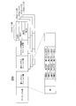


Classifications
-
- H—ELECTRICITY
- H04—ELECTRIC COMMUNICATION TECHNIQUE
- H04J—MULTIPLEX COMMUNICATION
- H04J1/00—Frequency-division multiplex systems
-
- H—ELECTRICITY
- H04—ELECTRIC COMMUNICATION TECHNIQUE
- H04L—TRANSMISSION OF DIGITAL INFORMATION, e.g. TELEGRAPHIC COMMUNICATION
- H04L27/00—Modulated-carrier systems
- H04L27/26—Systems using multi-frequency codes
-
- H—ELECTRICITY
- H04—ELECTRIC COMMUNICATION TECHNIQUE
- H04W—WIRELESS COMMUNICATION NETWORKS
- H04W16/00—Network planning, e.g. coverage or traffic planning tools; Network deployment, e.g. resource partitioning or cells structures
- H04W16/24—Cell structures
- H04W16/28—Cell structures using beam steering
-
- H—ELECTRICITY
- H04—ELECTRIC COMMUNICATION TECHNIQUE
- H04W—WIRELESS COMMUNICATION NETWORKS
- H04W28/00—Network traffic management; Network resource management
- H04W28/02—Traffic management, e.g. flow control or congestion control
- H04W28/06—Optimizing the usage of the radio link, e.g. header compression, information sizing, discarding information
-
- H—ELECTRICITY
- H04—ELECTRIC COMMUNICATION TECHNIQUE
- H04W—WIRELESS COMMUNICATION NETWORKS
- H04W84/00—Network topologies
- H04W84/02—Hierarchically pre-organised networks, e.g. paging networks, cellular networks, WLAN [Wireless Local Area Network] or WLL [Wireless Local Loop]
- H04W84/10—Small scale networks; Flat hierarchical networks
- H04W84/12—WLAN [Wireless Local Area Networks]
Definitions
- the present invention relates to a transmission device, a reception device, a wireless communication system, a wireless communication method, and a computer program.
- the frame preamble includes a VHT-SIG-A field
- the VHT-SIG-A field relates to a transmission method defined in the IEEE 802.11ac wireless LAN (Local Area Network) communication standard.
- ID group identifier
- STS space time stream
- data is transmitted to a plurality of terminals at the same timing by a spatial division multiple access (SDMA) technique.
- SDMA spatial division multiple access
- Patent Document 1 does not disclose that, in addition to the SDMA technique, an orthogonal frequency division multiple access (OFDMA) technique is applied to the wireless LAN.
- OFDMA orthogonal frequency division multiple access
- the present invention has been made in consideration of such circumstances, and a transmitter, a receiver, and a radio communication system capable of applying a space division multiple access technique and a frequency division multiple access technique to a wireless LAN. It is an object to provide a wireless communication method and a computer program.
- a transmission device includes a space-time stream including a payload portion in which a plurality of data is frequency-division multiplexed, and the data in the payload portion of the plurality of space-time streams that are space-division multiplexed.
- the information included in the header portion includes the information in the payload portion of the plurality of space-time streams that are spatially multiplexed.
- Information that individually indicates the receiving device of the data destination is included in an array format.
- the information included in the header portion includes the information of the payload portion of the plurality of space-time streams that are spatially multiplexed. It includes identification information indicating a combination of groups of data receiving apparatuses.
- the transmission unit may correspond to the identification information corresponding to the reception device and the identification information with respect to the reception device.
- a management frame for notifying information on the space division multiplexing and information on the frequency division multiplexing is transmitted by radio.
- the header portion indicates a pattern of arrangement of data addressed to the reception device in frequency division multiplexing of the payload portion. It further includes identification information.
- the transmission device according to one aspect of the present invention further includes an information generation unit that generates the information included in the header unit in any one of the transmission devices according to (1) to (5).
- a receiving device receives a frame transmitted wirelessly from any one of the above-described (1) to (3), and information included in a header portion of the received frame And a receiving unit for acquiring data from the payload portion of the received frame.
- the reception device is notified by a management frame among the reception unit that receives a frame transmitted by radio from the transmission device of (4), and the frame received by the reception unit.
- a management unit that manages identification information and information on space division multiplexing and frequency division multiplexing corresponding to the identification information, and the reception unit is included in a header portion of the received frame Based on the identification information and the information managed by the management unit, data is acquired from the payload portion of the received frame.
- a radio communication system includes a base station apparatus including any one of the transmission apparatuses (1) to (3) and a terminal apparatus including the reception apparatus (7).
- a radio communication system includes a base station device including the transmission device according to (4) above and a terminal device including the reception device according to (8) above.
- the transmission apparatus includes a space-time stream including a payload portion in which a plurality of data is frequency-division multiplexed, and the payload of the plurality of space-time streams that are space-division multiplexed.
- a computer program provides a computer of a transmission apparatus, wherein a space-time stream including a payload portion in which a plurality of data is frequency-division-multiplexed and a plurality of the space-time streams that are space-division-multiplexed
- a transmission step is performed for wirelessly transmitting a frame including a header portion including information indicating a receiving device that is a destination of the data in the payload portion.
- the present invention it is possible to apply the space division multiple access technology and the frequency division multiple access technology to the wireless LAN.
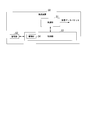
- FIG. 1 is an explanatory diagram showing a configuration example of a wireless LAN system 1 according to an embodiment of the present invention.
- the wireless LAN system 1 shown in FIG. 1 includes one base station device 2 and a plurality of terminal devices (Station: STA) 3a to 3k.
- the terminal devices 3a to 3k are referred to as “terminal device 3” unless otherwise distinguished.
- the base station apparatus 2 functions as a wireless LAN access point (AP).
- the terminal device 3 existing in the wireless LAN area (radio wave reachable range) of the base station device 2 is connected to another communication network (not shown) such as the Internet via the base station device 2 or the same. It is possible to communicate with other terminal devices 3 existing in the wireless LAN area.
- the wireless LAN system 1 uses SDMA (space division multiple access) technology and OFDMA (orthogonal frequency division multiple access) technology.
- the base station apparatus 2 performs SDMA using eight space-time streams (STS).
- STS space-time streams
- the eight space time streams STS1 to STS8 three space time streams STS1 to STS3 are used for communication with the four terminal apparatuses 3a to 3d belonging to the STA group G1.
- the two space time streams STS4 to STS5 are used for communication with the two terminal devices 3e to 3f belonging to the STA group G2.
- the three space time streams STS6 to STS7 are used for communication with the three terminal devices 3g to 3i belonging to the STA group G3.
- One space-time stream STS8 is used for communication with two terminal apparatuses 3j to 3k belonging to the STA group G4.
- the base station apparatus 2 further performs orthogonal frequency division multiplexing (OFDM) in the space-time stream used for each STA group G1 to G4.
- the spatio-temporal streams STS1 to STS3 used for the STA group G1 are frequency-divided into four resource units (Resource Unit: RU), and each RU is used for communication with each terminal device 3a to 3d.
- the space-time streams STS4 to STS5 used for the STA group G2 are frequency-divided into two RUs, and each RU is used for communication with each terminal device 3e to 3f.
- the space-time streams STS6 to STS7 used for the STA group G3 are frequency-divided into three RUs, and each RU is used for communication with each terminal device 3g to 3i.
- the space-time stream STS8 used for the STA group G4 is frequency-divided into two RUs, and each RU is used for communication with each terminal device 3j to 3k.
- the base station apparatus 2 is the same between the eight terminal apparatuses 3a to 3k by space division multiplexing (SDM) and orthogonal frequency division multiplexing (OFDM). Communication can be performed at the timing.
- SDM space division multiplexing
- OFDM orthogonal frequency division multiplexing
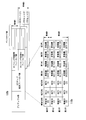
- FIG. 2 is a configuration diagram showing the transmission apparatus 10 according to an embodiment of the present invention.
- FIG. 3 is a configuration diagram illustrating a receiving device 50 according to an embodiment of the present invention.
- the base station apparatus 2 illustrated in FIG. 1 includes the transmission apparatus 10 illustrated in FIG.
- the terminal device 3 illustrated in FIG. 1 includes the receiving device 50 illustrated in FIG.
- the transmission device 10 of the base station device 2 and the reception device 50 of the terminal device 3 perform wireless communication in the downlink direction (direction from the base station device 2 to the terminal device 3).
- the base station device 2 includes a receiving device that performs wireless communication in the uplink direction (direction from the terminal device 3 to the base station device 2).
- the terminal device 3 includes a transmission device that performs uplink wireless communication.
- the transmission apparatus 10 illustrated in FIG. 2 includes a transmission unit 11, a control unit 12, and a storage unit 13.
- the transmission unit 11 includes a buffer / switch (BUF / SW) unit 21, STS data mapping units 22-1 to 22-4, coded modulation units 23-1 to 23-4, a spatial mapping unit 24, Fast Fourier transform (IFFT) units 25-1 to 25-N, guard interval (GI) / header adding units 26-1 to 26-N, and radio frequency (Radio Frequency: RF) Units 27-1 to 27-N and antennas 28-1 to 28-N.
- the control unit 12 includes an information generation unit 30.
- the transmission unit 11 transmits a frame used in wireless communication of the wireless LAN system 1.
- the control unit 12 performs various controls in the transmission device 10.
- the control unit 12 may perform various controls in the base station apparatus 2 including the transmission apparatus 10.
- the storage unit 13 stores various data.
- the STS data mapping unit 22-1 and the encoding modulation unit 23-1 are provided corresponding to the first STS set.
- the STS data mapping unit 22-2 and the encoding modulation unit 23-2 are provided corresponding to the second STS set.
- the STS data mapping unit 22-3 and the encoding modulation unit 23-3 are provided corresponding to the third STS set.
- the STS data mapping unit 22-4 and the encoding modulation unit 23-4 are provided corresponding to the fourth STS set.
- An STS set is a set of space-time streams. For example, in the example of FIG.
- the space-time streams STS1 to STS3 are the first STS set
- the space-time streams STS4 to STS5 are the second STS set
- the space-time streams STS6 to STS7 are the third STS set
- the space-time stream STS8 is the fourth STS set. Note that the combination of space-time streams and the number of space-time streams that constitute each STS set can be arbitrarily set. In this embodiment, four STS sets are used, but the number of STS sets is arbitrary.
- the IFFT units 25-1 to 25-N, the GI / header adding units 26-1 to 26-N, and the RF units 27-1 to 27-N correspond to the N antennas 28-1 to 28-N, respectively. Is provided.
- IFFT section 25-1, GI / header adding section 26-1, and RF section 27-1 are provided corresponding to antenna 28-1.
- N is 8
- the transmission apparatus 10 includes eight antennas 28-1 to 28-8. With eight antennas 28-1 to 28-8, up to eight space-time streams STS1 to STS8 can be spatially multiplexed as separate data sequences.
- STS data mapping units 22-1 to 22-4 when the STS data mapping units 22-1 to 22-4 are not particularly distinguished, they are referred to as “STS data mapping unit 22”, and when the coded modulation units 23-1 to 23-4 are not particularly distinguished, This is referred to as “encoded modulation unit 23”.
- encoded modulation unit 23 When IFFT sections 25-1 to 25-N are not particularly distinguished, they are referred to as “IFFT section 25”.
- GI / header adding sections 26-1 to 26-N When GI / header adding sections 26-1 to 26-N are not particularly distinguished, “GI / header adding section 26” is referred to.
- RF units 27-1 to 27-N are not particularly distinguished, they are referred to as “RF units 27”, and when the antennas 28-1 to 28-N are not particularly distinguished, they are referred to as “antennas 28”.
- the BUF / SW unit 21 receives a transmission data packet addressed to each terminal device 3 scheduled to be transmitted, and temporarily stores the received transmission data packet.
- the BUF / SW unit 21 notifies the control unit 12 of information on the stored transmission data packet.
- the control unit 12 Based on the information of the transmission data packet notified from the BUF / SW unit 21, the control unit 12 considers the packet size, the data rate at the time of transmission, the usable STS set, and the like and is stored in the BUF / SW unit 21.
- the STS data mapping unit 22 for allocating the transmission data packets being transmitted is determined.
- the control unit 12 notifies the BUF / SW unit 21 of the determined distribution destination STS data mapping unit 22.
- the BUF / SW unit 21 outputs the corresponding transmission data packet to the distribution-destination STS data mapping unit 22 notified from the control unit 12.
- the STS data mapping unit 22 maps the transmission data packet input from the BUF / SW unit 21 to the data sequence of the STS set based on an instruction from the control unit 12, and the encoded modulation unit 23 Output to.
- the encoding modulation unit 23 performs primary modulation on the data string input from the STS data mapping unit 22 at the encoding rate and modulation rate instructed by the control unit 12.
- the encoding modulation unit 23 outputs the data string after the primary modulation to the spatial mapping unit 24.
- the space mapping unit 24 maps the data sequence input from the encoding / modulating unit 23 to a space-time stream based on an instruction from the control unit 12.
- the space mapping unit 24 outputs the data string of the space-time stream after mapping to the corresponding IFFT unit 25.
- the IFFT unit 25 performs an inverse discrete Fourier transform on the data string input from the space mapping unit 24.
- the data string input from the space mapping unit 24 to the IFFT unit 25 is converted (secondary modulation) from the frequency-axis data string to the time-axis data by inverse discrete Fourier transform.
- the IFFT unit 25 outputs the data string after the secondary modulation to the GI / header adding unit 26.
- the GI / header adding unit 26 calculates the GI (Guard Interval), which is an interval for mitigating interference between the data in the header of the frame and the data before and after the data string input from the IFFT unit 25. Append.
- GI Guard Interval
- the GI / header adding unit 26 outputs the data in the header portion of the frame and the data string after adding the GI to the RF unit 27.
- the RF unit 27 converts the data string input from the GI / header adding unit 26 into an RF band radio signal and outputs the radio signal to the antenna 28. As a result, a radio signal is transmitted from the antenna 28.
- the information generation unit 30 of the control unit 12 generates data of the header part of the frame.
- the control unit 12 outputs the data of the header part of the frame generated by the information generation unit 30 to the GI / header addition unit 26.
- the receiving device 50 includes a receiving unit 51, a control unit 52, and a storage unit 53.
- the control unit 52 includes a management unit 54.
- the receiving unit 51 receives a frame used in wireless communication of the wireless LAN system 1.
- the control unit 52 performs various controls in the receiving device 50.
- the control unit 52 may perform various controls in the terminal device 3 including the receiving device 50.
- the storage unit 53 stores various data.
- the receiving unit 51 receives a frame transmitted wirelessly from the transmitting device 10 and acquires data from the payload portion of the received frame.
- the management unit 54 manages various data in the wireless communication of the wireless LAN system 1.
- the transmission data packet and the reception data packet are, for example, IP (Internet Protocol) packets stored in a data frame format defined in each wireless communication method.
- IP Internet Protocol
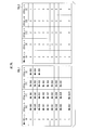
- FIG. 4 is an explanatory diagram showing a frame configuration example 1 of the present embodiment.
- 4 includes a preamble part, an STS map array field part, a timing synchronization field part, and a payload part.
- the preamble part, the STS map array field part, and the timing synchronization field part are included in the header part of the frame 100.
- the preamble portion includes a signal having a known signal pattern defined by the wireless LAN system 1.
- the receiving device 50 detects and receives the frame 100 by the preamble unit.
- the STS map array field part includes destination information 110.
- the preamble part and the STS map array field part may be transmitted omnidirectionally from the antenna 28 of the transmission apparatus 10.
- the preamble part and the STS map array field part are received by the terminal devices 3a to 3k of the STA groups G1 to G4 by being transmitted omnidirectionally.
- the timing synchronization field part and the payload part have a plurality of STS sets.
- the timing synchronization field part and the payload part have four STS sets [0] to [3].
- Each STS set [0] to [3] is transmitted from the antenna 28 of the transmission apparatus 10 with directivity.
- the STS set [0] composed of the space-time streams STS1 to STS3 is transmitted with directivity in the direction of the STA group G1.
- the STS set [0] is received by the terminal devices 3a to 3d of the STA group G1.
- the STS set [1] consisting of the space-time streams STS4 to STS5 is transmitted with directivity in the direction of the STA group G2.
- the STS set [1] is received by the terminal apparatuses 3e to 3f of the STA group G2.
- the STS set [2] composed of the space time streams STS6 to STS7 is transmitted with directivity in the direction of the STA group G3.
- the STS set [2] is received by the terminal devices 3g to 3i of the STA group G3.
- the STS set [3] consisting of the space time stream STS8 is transmitted with directivity in the direction of the STA group G4.
- the STS set [3] is received by the terminal devices 3j to 3k of the STA group G4.
- the timing synchronization field part includes a signal having a known signal pattern for synchronizing the STS set.
- the receiving device 50 can detect and receive the payload portion of the STS set by the timing synchronization field portion.
- a plurality of data is frequency division multiplexed.
- the payload part in one STS set, is frequency-divided into four RUs, and each RU stores data.
- the payload portion of the STS set [0] has RU [0] [0], RU [0] [1], RU [0] [2], and RU [0] [3] as four RUs.
- the payload part of the STS set [1] has RU [1] [0], RU [1] [1], RU [1] [2], and RU [1] [3] as four RUs.
- the payload part of the STS set [2] has RU [2] [0], RU [2] [1], RU [2] [2], and RU [2] [3] as four RUs.
- the payload part of the STS set [3] has RU [3] [0], RU [3] [1], RU [3] [2], and RU [3] [3] as four RUs.
- the destination information 110 included in the STS map array field will be described.
- the destination information 110 indicates a receiving device 50 that is a destination of data that is frequency-division multiplexed onto the payload portions of a plurality of space-time streams that are space-division multiplexed in the frame 100.
- the destination information 110 indicates the receiving device 50 that is the destination of the frequency division multiplexed data in the payload portions of the four STS sets [0] to [3] that are spatially multiplexed in the frame 100. .
- the destination information 110 includes information on space division multiplexing of a plurality of space time streams and information on frequency division multiplexing of the payload portion in an array format.
- the destination information 110 is configured in an array format of 4 rows and 4 columns.
- each row corresponds to each STS set, and each column corresponds to each RU.
- the X-th row and the Y-th column indicate the identifier (receiver ID [X]) of the destination device 50 of the data stored in the RU [X] [Y] of the STS set [X]. [Y]) is stored.
- the first row and the second column indicate the identifier (receiver ID [] of the destination device 50 of the data stored in the RU [1] [2] of the STS set [1]. 1] [2]) are stored.
- the receiving device 50 recognizes the STS set and the RU in which the data addressed to itself is stored based on its own identifier (receiver ID) and the destination information 110 included in the STS map array field portion.
- the receiver information includes the receiver ID in the destination information 110
- the receiving device 50 based on the index [X] [Y] of the location where the receiver ID is stored in the destination information 110, Data is acquired from RU [X] [Y] of STS set [X] in which data addressed to itself is stored.
- the above is the description of the frame configuration example 1.
- FIG. 5 is an explanatory diagram showing a frame configuration example 1-a of the present embodiment.
- Frame configuration example 1-a is a modification of frame configuration example 1 described above.
- a frame 100a illustrated in FIG. 4 has a configuration similar to that of the frame 100 illustrated in FIG.
- the STS map array field portion of the frame 100a includes information 110a.
- the information 110a is information in an array format in which an NSTS column and an NSTA column are further added to the destination information 110 shown in FIG.
- the NSTS column stores the number of space-time streams NSTS [0] to [3] constituting each STS set [0] to [3] in a row corresponding to each STS set [0] to [3].
- the Xth row of the NSTS column stores the number of space-time streams NSTS [X] constituting the STS set [X].
- the first row of the NSTS column stores the number of space-time streams NSTS [1] constituting the STS set [1].
- the number of space-time streams NSTS [0] to [3] constituting each STS set [0] to [3] is notified to the receiving apparatus 50 by the NSTS sequence. be able to.
- the number of space-time streams NSTS [0] to [3] constituting each STS set [0] to [3] can be made variable.
- the NSTA column stores the number NSTA [0] to [3] of the receiving apparatuses 50 accommodated in each STS set [0] to [3] in a row corresponding to each STS set [0] to [3].
- the Xth row of the NSTA column stores the number NSTA [X] of receiving devices 50 accommodated in the STS set [X].
- the first row of the NSTA column stores the number NSTA [1] of receiving devices 50 accommodated in the STS set [1].
- the number NSTA [0] to [3] of the number of receiving apparatuses 50 accommodated in each STS set [0] to [3] is notified to the receiving apparatus 50 by the NSTA sequence. be able to.
- the number NSTA [0] to [3] of receiving devices 50 accommodated in each STS set [0] to [3] is the number of RUs used by the payload part of each STS set [0] to [3], that is, each This corresponds to the number of columns that store the receiver IDs of the receivers 50 accommodated in the STS sets [0] to [3].
- information indicating the size of the STS map array field portion may be included in the head portion of the STS map array field portion, for example.
- the receiver ID of the receiving device 50 accommodated in each STS set [0] to [3] is provided for the row corresponding to each STS set [0] to [3] without providing the NSTA column.
- the end of the column of the row may be indicated by storing an identifier indicating the end of the data in the last column for storing.
- FIG. 6 is an explanatory diagram showing a frame configuration example 1-b of the present embodiment.
- Frame configuration example 1-b is a modification of frame configuration example 1-a described above.
- information 110b is included in the STS map array field portion.
- the information 110b is information in an array format in which a band ID string is further added to the information 110a shown in FIG.
- the band ID column corresponds to each STS set [0] to [3] with an identifier (band ID [0] to [3]) indicating the frequency band used for each STS set [0] to [3].
- the Xth row of the band ID column stores a band ID [X] indicating a frequency band used for the STS set [X].
- the first row of the band ID column stores a band ID [1] indicating a frequency band used for the STS set [1].
- NSTS [X] of the STS set [X] is not subjected to space-time multiplexing using a space-time stream. For example, “0” is used.
- NSTS [0] indicates a value indicating that space-time multiplexing is not performed by the space-time stream. “0” is used.
- the frequency band B of the STS sets [1] to [3] space / time multiplexing is performed by the space-time stream, so that the NSTS [1] to [3] include the STS sets [0] to [3].
- the value of the number of spatio-temporal streams that make up is used.
- the frequency band used for the frame 100b includes a frequency band that performs space / time multiplexing using a space-time stream and a frequency band that does not perform space-time multiplexing using a space-time stream. Can be included.
- data addressed to a receiving device that supports space / time multiplexing by a space-time stream and data addressed to a receiving device that does not support space-time multiplexing by a space-time stream are included in the same frame 100b. Can be sent.
- the above is the description of the frame configuration example 1-b.
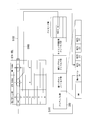
- FIG. 7 is an explanatory diagram showing a frame configuration example 2 of the present embodiment.
- a frame 200 shown in FIG. 7 includes a preamble part, a first signal field part, a second signal field part, a timing synchronization field part, and a payload part.
- the preamble part, the first signal field part, the second signal field part, and the timing synchronization field part are included in the header part of the frame 200.
- the preamble portion includes a signal having a known signal pattern defined by the wireless LAN system 1.
- the receiving device 50 detects and receives the frame 200 by the preamble part.
- the first signal field part includes bandwidth (BW) information, an MA (Multi-Access) pattern identifier (MA pattern ID), and NSTS [0] to [3].
- BW bandwidth
- MA pattern ID Multiple Access
- NSTS [0] to [3] subfields for storing BW information, MA pattern ID, and NSTS [0] to [3] are provided.
- the BW information indicates a frequency bandwidth used for the frame 200.
- the MA pattern ID is an identifier indicating a combination of receiving apparatuses 50 accommodated in each STS set [0] to [3].
- NSTS [0] to [3] indicate the number of space-time streams constituting the STS sets [0] to [3].
- NSTS [X] is the number of space-time streams that make up the STS set [X].
- the preamble part and the first signal field part may be transmitted omnidirectionally from the antenna 28 of the transmission apparatus 10. This is the same as the preamble part and the STS map array field part of the frame configuration example 1 described above.
- the second signal field part, the timing synchronization field part, and the payload part have a plurality of STS sets.
- the second signal field portion, the timing synchronization field portion, and the payload portion have four STS sets [0] to [3].
- Each STS set [0] to [3] is transmitted from the antenna 28 of the transmission apparatus 10 with directivity. This is the same as the STS sets [0] to [3] of the frame configuration example 1 described above.
- the second signal field part includes information such as a modulation method of data stored in the RU of the payload part.
- the timing synchronization field portion includes a signal having a known signal pattern for synchronizing the STS set.
- the receiving device 50 can detect and receive the payload portion of the STS set by the timing synchronization field portion.
- a plurality of data is frequency division multiplexed.
- the payload part is frequency-divided into four RU [0] to [3], and each RU [0] 0] to [3] store data.
- FIG. 8 is a diagram illustrating a configuration example of the MA pattern ID management table AP_TBL provided in the transmission apparatus 10 (AP).
- the MA pattern ID management table AP_TBL includes a STA group management table TBL1 and an NSTS management table TBL2 illustrated in FIG.
- the MA pattern ID management table AP_TBL (STA group management table TBL1 and NSTS management table TBL2) is stored in the storage unit 13 of the transmission device 10.
- the STA group management table TBL1 stores, for each MA pattern ID, an identifier (MA-SG ID) of “Multi-Access STA group (MA-SG)” corresponding to each STS set [0] to [3].
- MA-SG is a group of receiving apparatuses 50 accommodated in one STS set.
- the STA group management table TBL1 indicates, for each MA pattern ID, the MA-SG of the receiving device 50 that is the destination of data that is frequency-multiplexed into each STS set [0] to [3].
- NSTS management table TBL2 stores the value of the number of spatiotemporal streams constituting each STS set [0] to [3] for each MA pattern ID.
- NSTS management table TBL2 indicates the number of space-time streams used for each STS set [0] to [3] for each MA pattern ID.
- FIG. 9 is a diagram illustrating a configuration example of the MA-SG management table TBL3 provided in the transmission apparatus 10.
- the MA-SG management table TBL3 is stored in the storage unit 13 of the transmission device 10.
- the MA-SG management table TBL3 stores identification information indicating the receiving device 50 belonging to the MA-SG for each MA-SG identifier (MA-SG ID).
- MA-SG ID the MA-SG identifier
- STA [0] to [n] identification information of the receiving device 50 (STA [0] to [n]) of the data destination frequency-multiplexed to the same STS set Is shown.
- the control unit 12 of the transmission apparatus 10 manages the MA pattern ID management table AP_TBL (STA group management table TBL1 and NSTS management table TBL2) and the MA-SG management table TBL3. Based on the MA pattern ID management table AP_TBL (STA group management table TBL1 and NSTS management table TBL2) and the MA-SG management table TBL3, the information generation unit 30 includes the MA pattern ID and NSTS included in the first signal field portion of the frame 200. [0] to [3] are generated.
- FIG. 10 is a diagram illustrating a configuration example of the MA pattern ID management frame 210.
- the transmission device 10 individually transmits the MA pattern ID management frame 210 to the reception device 50.
- the MA pattern ID management frame 210 is a management frame that notifies the receiving apparatus 50 of the MA pattern ID corresponding to the receiving apparatus 50, and the STA index and MA index corresponding to the MA pattern ID.
- the MA pattern ID management frame 210 includes a frame type ID section, a membership status array section, an STA index (STA Index) array section, and an MA index (MAIndex) array section.
- STA Index STA Index
- MAIndex MA index
- an identifier (ID) of the MA pattern ID management frame is stored.
- the MA pattern ID management frame 210 may be configured in the form of a MAC (Media Access Control) frame for communicating management information, for example.
- MAC Media Access Control
- the membership status array part includes statuses corresponding to all MA pattern IDs. Since the total number of MA pattern IDs is “m + 1”, the membership status array section includes “m + 1” statuses [0] to [m] respectively corresponding to “m + 1” MA pattern IDs.
- FIG. 10 as specific examples of statuses [0] to [m], in parentheses, addressed to “STA01” based on the MA pattern ID management table AP_TBL in FIG. 8 and the MA-SG management table TBL3 in FIG.
- the values of status [0] to [m] of the MA pattern ID management frame 210 to be transmitted are shown.
- the STA index array part includes “m + 1” STA indexes [0] to [m] respectively corresponding to “m + 1” MA pattern IDs.
- FIG. 10 as a specific example of the STA indexes [0] to [m], in parentheses, addressed to “STA01” based on the MA pattern ID management table AP_TBL in FIG. 8 and the MA-SG management table TBL3 in FIG.
- the values of the STA indexes [0] to [m] of the MA pattern ID management frame 210 transmitted to the are shown.
- the statuses [0] to [m] in the membership status array section shown in FIG. 10 the statuses [0], [1], [2] and [5] which are “1” are “1”. is there.
- the STA number of “STA01” is STA [1] (see FIG. 9).
- the STA number of “STA01” is STA [0] (see FIG. 9). . Therefore, as shown in FIG. 10, the STA indexes [0], [1], and [2] are “1”, and the STA index [5] is “0”.
- the STA index corresponding to “5” is recognized. Note that the STA index corresponding to the status of “0” may be indefinite.
- the MA index array part includes “m + 1” MA indexes [0] to [m] respectively corresponding to “m + 1” MA pattern IDs.
- FIG. 10 shows, as a specific example of the MA indexes [0] to [m], to “STA01” in parentheses based on the MA pattern ID management table AP_TBL in FIG. 8 and the MA-SG management table TBL3 in FIG.
- the values of the MA indexes [0] to [m] of the MA pattern ID management frame 210 transmitted to are shown.
- the statuses [0], [1], [2] and [5] which are “1” are “1”. is there.
- the MA index corresponding to “5” is recognized. Note that the MA index corresponding to the status “0” may be indefinite.
- FIG. 11 is a diagram illustrating a configuration example of the MA pattern ID management table STA_TBL provided in the reception device 50 (STA).
- the MA pattern ID management table STA_TBL is stored in the storage unit 53 of the receiving device 50.
- the management unit 54 of the reception device 50 creates an MA pattern ID management table STA_TBL based on the MA pattern ID management frame 210 received from the transmission device 10.
- FIG. 11 shows an MA pattern ID management table STA_TBL created by the management unit 54 of the receiving device 50 of “STA01” as a specific example of the MA pattern ID management table STA_TBL.
- the receiving unit 51 notifies the management unit 54 of the MA pattern ID included in the first signal field portion of the frame 200 received from the transmitting device 10.
- the management unit 54 acquires the STA index and MA index related to the MA pattern ID notified from the reception unit 51 from the MA pattern ID management table STA_TBL, and notifies the reception unit 51 of the acquired STA index and MA index.
- the receiving unit 51 acquires a received data packet from the payload part of the received frame 200 based on the STA index and the MA index notified from the management unit 54.
- FIG. 11 shows a specific example of the operation of the receiving device 50 of “STA01”.
- the receiving unit 51 of the receiving device 50 of “STA01” notifies the management unit 54 of the MA pattern ID “1” included in the first signal field portion of the frame 200 received from the transmitting device 10 (step S101).
- the management unit 54 acquires the STA index “1” and the MA index “0” regarding the MA pattern ID “1” notified from the reception unit 51 from the MA pattern ID management table STA_TBL, and acquires the acquired STA index “1” and MA The index “0” is notified to the receiving unit 51.
- the receiving unit 51 refers to NSTS [0] in the first signal field unit corresponding to the MA index “0” notified from the management unit 54 (step S102).
- the value of NSTS [0] is “3” (see NSTS management table TBL2 in FIG. 8). That is, the number of space-time streams constituting the STS set [0] including the data addressed to the receiving device 50 of “STA01” is three. Thereby, the receiving unit 51 recognizes that the number of space-time streams constituting the STS set [0] including the data addressed to itself is three. In addition, the receiving unit 51 recognizes RU [1] in which data addressed to itself is stored based on the STA index “1” notified from the management unit 54. The receiving unit 51 decodes the data stored in RU [1] for the three space-time streams constituting the STS set [0] (step S103). The receiving unit 51 acquires a received data packet as a result of the decoding.
- the receiver ID is included in the STS map array field using the array format information 110, 110a and 110b. Increases in size. According to this frame configuration example 2, by using the MA pattern ID, it is possible to suppress an increase in the size of the header portion of the frame.
- the transmitting apparatus 10 notifies the receiving apparatus 50 of the MA pattern ID corresponding to the receiving apparatus 50, the STA index corresponding to the MA pattern ID, and the MA index by the MA pattern ID management frame 210. be able to. Thereby, the receiving apparatus 50 can create and hold the MA pattern ID management table STA_TBL. Note that the MA pattern ID management table STA_TBL may be set and held in advance for the receiving device 50.
- the maximum possible number of management data such as the MA pattern ID may be determined according to the amount of data allowed to be included in the header portion of the frame. The above is the description of the frame configuration example 2.
- FIG. 12 is an explanatory diagram showing a frame configuration example 2-a of the present embodiment.
- Frame configuration example 2-a is a modification of frame configuration example 2 described above.
- a frame 200a illustrated in FIG. 12 has a configuration similar to that of the frame 200 illustrated in FIG.
- the first signal field portion of the frame 200a includes the MA pattern ID and NSTS for each sub-band (SBW).
- the first signal field portion of the frame 200a includes SBW information [0] to [3], NSTS [0] to [3], and MA pattern ID [[corresponding to the STS sets [0] to [3]. 0] to [3].
- the STS set [x] corresponds to SBW information [x], NSTS [x], and MA pattern ID [x].
- the frequency band used for the frame 200a a frequency band for performing space-time multiplexing by a space-time stream, and a space-time stream And a frequency band in which space / time multiplexing is not performed.
- a frequency band for performing space-time multiplexing by a space-time stream a frequency band for performing space-time multiplexing by a space-time stream
- a space-time stream a frequency band for performing space-time multiplexing by a space-time stream
- a space-time stream a frequency band in which space / time multiplexing is not performed.
- FIG. 13 is an explanatory diagram showing a frame configuration example 2-b of the present embodiment.
- Frame configuration example 2-b is a modification of frame configuration example 2 described above.
- a frame 200b shown in FIG. 13 has the same configuration as the frame 200 shown in FIG.
- the second signal field portion of the frame 200b includes the “RU BW array”.
- the “RU BW array” in the second signal field portion of the STS set [x] includes bandwidth information “RU BW [0] indicating the bandwidth of the RU [0] to [3] of the payload portion of the STS set [x]. To [3] ”.
- Bandwidth information “RU BW [x]” indicates the bandwidth of RU [x].
- the management unit 54 of the receiving device 50 refers to the bandwidth information “RU BW [x]” indicated by the STA index “x” in the MA pattern ID management table STA_TBL related to the MA pattern ID in the first signal field portion of the frame 200b. Then, the bandwidth of RU [x] in which the data addressed to the receiving device 50 is stored is recognized. As a result, the frequency band RU division method in each of the STS sets [0] to [3] can be made variable.
- the above is the description of the frame configuration example 2-b.
- FIG. 14 is an explanatory diagram showing a frame configuration example 2-c of the present embodiment.
- Frame configuration example 2-c is a modification of frame configuration example 2 described above.
- a frame 200c illustrated in FIG. 14 has the same configuration as the frame 200 illustrated in FIG.
- the first signal field portion of the frame 200c further includes “RU order pattern array” in addition to the information of the first signal field portion shown in FIG.
- the “RU order pattern array” includes “RU order pattern IDs [0] to [3]” corresponding to the STS sets [0] to [3].
- “RU order pattern ID [x]” corresponds to the STS set [x].
- FIG. 15 is a diagram showing a configuration example of the RU-order pattern ID management table TBL10.
- the RU-order pattern ID management table TBL10 is shared in advance between the transmission device 10 and the reception device 50.
- the transmission device 10 stores the RU-order pattern ID management table TBL10 in the storage unit 13.
- the receiving device 50 stores the RU-order pattern ID management table TBL10 in the storage unit 53.
- the RU-order pattern ID management table TBL10 indicates, for each “RU ⁇ order pattern ID”, RU [0] to [3] corresponding to each STA index in “RU order pattern ID”.
- this frame configuration example 2-c it is possible to vary the way in which the RUs used for frequency division multiplexing in each of the STS sets [0] to [3] are allocated to the receiving device 50.
- the above is the description of the frame configuration example 2-c.
- FIG. 16 is an explanatory diagram showing a frame configuration example 2-d of this embodiment.
- Frame configuration example 2-d is a modification of frame configuration example 2-b described above.
- a frame 200d shown in FIG. 16 has the same configuration as the frame 200b shown in FIG.
- the second signal field portion of the frame 200d further includes “RU order pattern ID”.
- the “RU order pattern ID” in the second signal field part of the STS set [x] is the “RU order pattern ID” regarding the RUs [0] to [3] of the payload part of the STS set [x].
- the transmitting apparatus 10 and the receiving apparatus 50 share in advance the RU-order pattern ID management table TBL10 shown in FIG. 15 as in the frame configuration example 2-c described above. The above is the description of the frame configuration example 2-d.
- the “RU ⁇ ⁇ ⁇ ⁇ BW array” may be included in the first signal field portion.
- it is not necessary to include information on the specific receiving device 50 in the MA-SG management table TBL3 and the size of the MA-SG management table TBL3 is reduced. Can do.
- the technology of space division multiple access and the technology of frequency division multiple access can be applied to the wireless LAN system 1. Accordingly, it is possible to increase the number of destination receiving devices 50 that can transmit data from the transmitting device 10 at the same timing. This has the effect of shortening the waiting time for data transmission and improving the communication efficiency.
- a computer program for realizing the functions of the transmission device 10 or the reception device 50 described above is recorded on a computer-readable recording medium, and the program recorded on the recording medium is read into a computer system and executed. It may be.
- the “computer system” may include an OS and hardware such as peripheral devices.
- “Computer-readable recording medium” refers to a flexible disk, a magneto-optical disk, a ROM, a writable nonvolatile memory such as a flash memory, a portable medium such as a DVD (Digital Versatile Disc), and a built-in computer system.
- a storage device such as a hard disk.
- the “computer-readable recording medium” means a volatile memory (for example, DRAM (Dynamic DRAM) in a computer system that becomes a server or a client when a program is transmitted through a network such as the Internet or a communication line such as a telephone line. Random Access Memory)), etc., which hold programs for a certain period of time.
- the program may be transmitted from a computer system storing the program in a storage device or the like to another computer system via a transmission medium or by a transmission wave in the transmission medium.
- the “transmission medium” for transmitting the program refers to a medium having a function of transmitting information, such as a network (communication network) such as the Internet or a communication line (communication line) such as a telephone line.
- the program may be for realizing a part of the functions described above. Furthermore, what can implement
Landscapes
- Engineering & Computer Science (AREA)
- Computer Networks & Wireless Communication (AREA)
- Signal Processing (AREA)
- Mobile Radio Communication Systems (AREA)
Abstract
基地局装置は、複数のデータが周波数分割多重されるペイロード部を含む空間時間ストリームと、空間分割多重される複数の空間時間ストリームのペイロード部のデータの宛先の受信装置を示す情報を含むヘッダ部と、を含むフレームを無線により送信する送信部を備え、端末装置は、基地局装置から無線により送信されたフレームを受信し、該受信したフレームのヘッダ部に含まれる情報に基づいて、該受信したフレームのペイロード部からデータを取得する受信部を備える。
Description
本発明は、送信装置、受信装置、無線通信システム、無線通信方法、及び、コンピュータプログラムに関する。
本願は、2015年11月2日に、日本に出願された特願2015-216079号に基づき優先権を主張し、その内容をここに援用する。
本願は、2015年11月2日に、日本に出願された特願2015-216079号に基づき優先権を主張し、その内容をここに援用する。
従来の無線通信技術として、例えば特許文献1に記載される技術が知られている。特許文献1の従来技術では、IEEE802.11ac方式の無線LAN(Local Area Network)の通信規格に規定される送信方法に関し、フレームのプリアンブルがVHT-SIG-Aフィールドを備え、VHT-SIG-Aフィールドがグループ識別子(ID)サブフィールドと空間時間ストリーム(STS)サブフィールドを備える。特許文献1の従来技術は、空間分割多元接続(Spatial Division Multiple Access:SDMA)の技術により複数の端末宛てに同じタイミングでデータを送信している。
しかし、上述した特許文献1の従来技術では、無線LANにおいて、SDMAの技術に加えてさらに直交周波数分割多元接続(Orthogonal Frequency Division Multiple Access:OFDMA)の技術を適用することは開示されていなかった。
本発明は、このような事情を考慮してなされたものであり、空間分割多元接続の技術と周波数分割多元接続の技術とを無線LANに適用することができる送信装置、受信装置、無線通信システム、無線通信方法、及び、コンピュータプログラムを提供することを課題とする。
(1)本発明の一態様の送信装置は、複数のデータが周波数分割多重されるペイロード部を含む空間時間ストリームと、空間分割多重される複数の前記空間時間ストリームの前記ペイロード部の前記データの宛先の受信装置を示す情報を含むヘッダ部と、を含むフレームを無線により送信する送信部を備える。
(2)本発明の一態様の送信装置は、上記(1)の送信装置において、前記ヘッダ部に含まれる前記情報は、前記空間分割多重される複数の前記空間時間ストリームの前記ペイロード部の前記データの宛先の受信装置を個別に示す情報を配列形式で含む。
(3)本発明の一態様の送信装置は、上記(1)の送信装置において、前記ヘッダ部に含まれる前記情報は、前記空間分割多重される複数の前記空間時間ストリームの前記ペイロード部の前記データの宛先の受信装置のグループの組合せを示す識別情報を含む。
(4)本発明の一態様の送信装置は、上記(3)の送信装置において、前記送信部は、受信装置に対して、該受信装置に該当する前記識別情報と、該識別情報に該当する前記空間分割多重についての情報及び前記周波数分割多重についての情報と、を通知する管理フレームを無線により送信する。
(5)本発明の一態様の送信装置は、上記(3)又は(4)の送信装置において、前記ヘッダ部は、前記ペイロード部の周波数分割多重における受信装置宛てのデータの配置のパターンを示す識別情報をさらに含む。
(6)本発明の一態様の送信装置は、上記(1)から(5)のいずれかの送信装置において、前記ヘッダ部に含まれる前記情報を生成する情報生成部をさらに備える。
(2)本発明の一態様の送信装置は、上記(1)の送信装置において、前記ヘッダ部に含まれる前記情報は、前記空間分割多重される複数の前記空間時間ストリームの前記ペイロード部の前記データの宛先の受信装置を個別に示す情報を配列形式で含む。
(3)本発明の一態様の送信装置は、上記(1)の送信装置において、前記ヘッダ部に含まれる前記情報は、前記空間分割多重される複数の前記空間時間ストリームの前記ペイロード部の前記データの宛先の受信装置のグループの組合せを示す識別情報を含む。
(4)本発明の一態様の送信装置は、上記(3)の送信装置において、前記送信部は、受信装置に対して、該受信装置に該当する前記識別情報と、該識別情報に該当する前記空間分割多重についての情報及び前記周波数分割多重についての情報と、を通知する管理フレームを無線により送信する。
(5)本発明の一態様の送信装置は、上記(3)又は(4)の送信装置において、前記ヘッダ部は、前記ペイロード部の周波数分割多重における受信装置宛てのデータの配置のパターンを示す識別情報をさらに含む。
(6)本発明の一態様の送信装置は、上記(1)から(5)のいずれかの送信装置において、前記ヘッダ部に含まれる前記情報を生成する情報生成部をさらに備える。
(7)本発明の一態様の受信装置は、上記(1)から(3)のいずれかの送信装置から無線により送信されたフレームを受信し、該受信した前記フレームのヘッダ部に含まれる情報に基づいて、該受信した前記フレームのペイロード部からデータを取得する受信部を備える。
(8)本発明の一態様の受信装置は、上記(4)の送信装置から無線により送信されたフレームを受信する受信部と、前記受信部が受信した前記フレームのうち管理フレームで通知される、識別情報と該識別情報に該当する空間分割多重についての情報及び周波数分割多重についての情報と、を管理する管理部と、を備え、前記受信部は、受信した前記フレームのヘッダ部に含まれる識別情報と前記管理部が管理する情報とに基づいて、該受信した前記フレームのペイロード部からデータを取得する。
(9)本発明の一態様の無線通信システムは、上記(1)から(3)のいずれかの送信装置を備える基地局装置と、上記(7)の受信装置を備える端末装置とを備える。
(10)本発明の一態様の無線通信システムは、上記(4)の送信装置を備える基地局装置と、上記(8)の受信装置を備える端末装置とを備える。
(11)本発明の一態様の無線通信方法は、送信装置が、複数のデータが周波数分割多重されるペイロード部を含む空間時間ストリームと、空間分割多重される複数の前記空間時間ストリームの前記ペイロード部の前記データの宛先の受信装置を示す情報を含むヘッダ部とを含むフレームを無線により送信する送信ステップを含む。
(12)本発明の一態様のコンピュータプログラムは、送信装置のコンピュータに、複数のデータが周波数分割多重されるペイロード部を含む空間時間ストリームと、空間分割多重される複数の前記空間時間ストリームの前記ペイロード部の前記データの宛先の受信装置を示す情報を含むヘッダ部とを含むフレームを無線により送信する送信ステップを実行させる。
本発明によれば、空間分割多元接続の技術と周波数分割多元接続の技術とを無線LANに適用することができるという効果が得られる。
以下、図面を参照し、本発明の実施形態について説明する。
図1は、本発明の一実施形態に係る無線LANシステム1の構成例を示す説明図である。図1に示す無線LANシステム1は、1つの基地局装置2と複数の端末装置(Station:STA)3a~3kを備える。以下の説明において、端末装置3a~3kを特に区別しないときは「端末装置3」と称する。基地局装置2は、無線LANのアクセスポイント(Access Point:AP)として機能する。基地局装置2の無線LANエリア(電波到達範囲)内に存在する端末装置3は、基地局装置2を経由して、インターネット等の他の通信ネットワーク(図示せず)に接続したり、又は同じ無線LANエリア内に存在する他の端末装置3と通信したりすることができる。
図1は、本発明の一実施形態に係る無線LANシステム1の構成例を示す説明図である。図1に示す無線LANシステム1は、1つの基地局装置2と複数の端末装置(Station:STA)3a~3kを備える。以下の説明において、端末装置3a~3kを特に区別しないときは「端末装置3」と称する。基地局装置2は、無線LANのアクセスポイント(Access Point:AP)として機能する。基地局装置2の無線LANエリア(電波到達範囲)内に存在する端末装置3は、基地局装置2を経由して、インターネット等の他の通信ネットワーク(図示せず)に接続したり、又は同じ無線LANエリア内に存在する他の端末装置3と通信したりすることができる。
無線LANシステム1は、SDMA(空間分割多元接続)の技術とOFDMA(直交周波数分割多元接続)の技術とを使用する。図1の例では、基地局装置2は、8個の空間時間ストリーム(Space-Time Stream:STS)を使用してSDMAを行う。8個の空間時間ストリームSTS1~8のうち、3個の空間時間ストリームSTS1~3は、STAグループG1に属する4台の端末装置3a~3dとの通信に使用される。2個の空間時間ストリームSTS4~5は、STAグループG2に属する2台の端末装置3e~3fとの通信に使用される。3個の空間時間ストリームSTS6~7は、STAグループG3に属する3台の端末装置3g~3iとの通信に使用される。1個の空間時間ストリームSTS8は、STAグループG4に属する2台の端末装置3j~3kとの通信に使用される。
基地局装置2は、さらに、各STAグループG1~G4に使用される空間時間ストリームにおいて、直交周波数分割多重(Orthogonal Frequency Division Multiplexing:OFDM)を行う。STAグループG1に使用される空間時間ストリームSTS1~3は、周波数帯域が4個のリソースユニット(Resource Unit:RU)に周波数分割され、各RUが各端末装置3a~3dとの通信に使用される。STAグループG2に使用される空間時間ストリームSTS4~5は、周波数帯域が2個のRUに周波数分割され、各RUが各端末装置3e~3fとの通信に使用される。STAグループG3に使用される空間時間ストリームSTS6~7は、周波数帯域が3個のRUに周波数分割され、各RUが各端末装置3g~3iとの通信に使用される。STAグループG4に使用される空間時間ストリームSTS8は、周波数帯域が2個のRUに周波数分割され、各RUが各端末装置3j~3kとの通信に使用される。
図1の構成例によれば、基地局装置2は、空間分割多重(Space Division Multiplexing:SDM)と直交周波数分割多重(OFDM)とにより、8台の端末装置3a~3kとの間で、同じタイミングで通信を行うことができる。
図2は、本発明の一実施形態に係る送信装置10を示す構成図である。図3は、本発明の一実施形態に係る受信装置50を示す構成図である。図1に示す基地局装置2は、図2に示す送信装置10を備える。図1に示す端末装置3は、図3に示す受信装置50を備える。無線LANシステム1において、基地局装置2の送信装置10と端末装置3の受信装置50は、下り方向(基地局装置2から端末装置3への方向)の無線通信を行う。なお、基地局装置2は、上り方向(端末装置3から基地局装置2への方向)の無線通信を行う受信装置を備える。また、端末装置3は、上り方向の無線通信を行う送信装置を備える。
まず図2を参照して送信装置10を説明する。図2に示す送信装置10は、送信部11と、制御部12と、記憶部13を備える。送信部11は、バッファ・スイッチ(BUF・SW)部21と、STSデータマッピング部22-1~22-4と、符号化変調部23-1~23-4と、空間マッピング部24と、逆高速フーリエ変換(Inverse Fast Fourier Transform:IFFT)部25-1~25-Nと、ガードインターバル(Guard Interval:GI)・ヘッダ付加部26-1~26-Nと、無線周波数(Radio Frequency:RF)部27-1~27-Nと、アンテナ28-1~28-Nを備える。制御部12は情報生成部30を備える。
送信装置10において、送信部11は、無線LANシステム1の無線通信で使用されるフレームの送信を行う。制御部12は、送信装置10における各種の制御を行う。なお、制御部12は、送信装置10を含めて基地局装置2における各種の制御を行うものであってもよい。記憶部13は、各種のデータを記憶する。
送信部11において、STSデータマッピング部22-1と符号化変調部23-1は第1のSTSセットに対応して設けられている。STSデータマッピング部22-2と符号化変調部23-2は第2のSTSセットに対応して設けられている。STSデータマッピング部22-3と符号化変調部23-3は第3のSTSセットに対応して設けられている。STSデータマッピング部22-4と符号化変調部23-4は第4のSTSセットに対応して設けられている。STSセットは、空間時間ストリームの組である。例えば、図1の例では、空間時間ストリームSTS1~STS3が第1のSTSセットであり、空間時間ストリームSTS4~STS5が第2のSTSセットであり、空間時間ストリームSTS6~STS7が第3のSTSセットであり、空間時間ストリームSTS8が第4のSTSセットである。なお、各STSセットを構成する空間時間ストリームの組合せ及び空間時間ストリームの個数は、任意に設定することができる。また、本実施形態では、4個のSTSセットを使用するが、STSセットの個数は任意である。
IFFT部25-1~25-NとGI・ヘッダ付加部26-1~26-NとRF部27-1~27-Nは、N個のアンテナ28-1~28-Nの各々に対応して設けられている。例えば、IFFT部25-1とGI・ヘッダ付加部26-1とRF部27-1は、アンテナ28-1に対応して設けられている。図1の例では、Nは8であり、送信装置10は、8個のアンテナ28-1~28-8を備える。8個のアンテナ28-1~28-8により、最大8個の空間時間ストリームSTS1~STS8を各々別個のデータ系列として空間分割多重することができる。
以下の説明において、STSデータマッピング部22-1~22-4を特に区別しないときは「STSデータマッピング部22」と称し、符号化変調部23-1~23-4を特に区別しないときは「符号化変調部23」と称する。また、IFFT部25-1~25-Nを特に区別しないときは「IFFT部25」と称し、GI・ヘッダ付加部26-1~26-Nを特に区別しないときは「GI・ヘッダ付加部26」と称し、RF部27-1~27-Nを特に区別しないときは「RF部27」と称し、アンテナ28-1~28-Nを特に区別しないときは「アンテナ28」と称する。
BUF・SW部21は、送信予定の各端末装置3宛ての送信データパケットを受信し、受信した送信データパケットを一時的に格納する。BUF・SW部21は、格納した送信データパケットの情報を制御部12に通知する。制御部12は、BUF・SW部21から通知された送信データパケットの情報に基づいて、パケットサイズや送信時のデータレート、使用可能なSTSセットなどを考慮し、BUF・SW部21に格納されている送信データパケットを振り分けるSTSデータマッピング部22を決定する。制御部12は、決定した振り分け先のSTSデータマッピング部22をBUF・SW部21へ通知する。BUF・SW部21は、制御部12から通知された振り分け先のSTSデータマッピング部22へ、該当する送信データパケットを出力する。
STSデータマッピング部22は、BUF・SW部21から入力された送信データパケットを、制御部12からの指示に基づいてSTSセットのデータ列にマッピングし、マッピング後のデータ列を符号化変調部23へ出力する。符号化変調部23は、STSデータマッピング部22から入力されたデータ列を、制御部12から指示される符号化レートと変調レートで1次変調を行う。符号化変調部23は、1次変調後のデータ列を空間マッピング部24へ出力する。空間マッピング部24は、符号化変調部23から入力されたデータ列を、制御部12からの指示に基づいて空間時間ストリームにマッピングする。空間マッピング部24は、マッピング後の空間時間ストリームのデータ列を該当するIFFT部25へ出力する。
IFFT部25は、空間マッピング部24から入力されたデータ列に対して逆離散フーリエ変換を行う。空間マッピング部24からIFFT部25に入力されたデータ列は、逆離散フーリエ変換により周波数軸のデータ列から時間軸のデータへ変換(2次変調)される。IFFT部25は、2次変調後のデータ列をGI・ヘッダ付加部26へ出力する。GI・ヘッダ付加部26は、IFFT部25から入力されたデータ列に対して、フレームのヘッダ部のデータと、前後のデータとの干渉を緩和するためのインターバルであるGI(Guard Interval)とを付加する。GI・ヘッダ付加部26は、フレームのヘッダ部のデータとGIを付加後のデータ列をRF部27へ出力する。RF部27は、GI・ヘッダ付加部26から入力されたデータ列をRF帯域の無線信号に変換してアンテナ28へ出力する。これにより、アンテナ28から無線信号が送信される。制御部12の情報生成部30は、フレームのヘッダ部のデータを生成する。制御部12は、情報生成部30が生成したフレームのヘッダ部のデータをGI・ヘッダ付加部26へ出力する。
次に図3を参照して受信装置50を説明する。図3に示す受信装置50は、受信部51と、制御部52と、記憶部53を備える。制御部52は管理部54を備える。受信装置50において、受信部51は、無線LANシステム1の無線通信で使用されるフレームの受信を行う。制御部52は、受信装置50における各種の制御を行う。なお、制御部52は、受信装置50を含めて端末装置3における各種の制御を行うものであってもよい。記憶部53は、各種のデータを記憶する。
受信部51は、送信装置10から無線により送信されたフレームを受信し、該受信したフレームのペイロード部からデータを取得する。管理部54は、無線LANシステム1の無線通信における各種のデータの管理を行う。
なお、送信データパケット及び受信データパケットは、例えば各々の無線通信方式に規定されるデータフレームの形式によって格納されたIP(Internet Protocol)パケットである。
次に本実施形態の送信装置10が無線により送信するフレームの構成例を説明する。
[フレーム構成例1]
図4は、本実施形態のフレーム構成例1を示す説明図である。図4に示すフレーム100は、プリアンブル部と、STSマップ配列フィールド部と、タイミング同期用フィールド部と、ペイロード部を備える。プリアンブル部とSTSマップ配列フィールド部とタイミング同期用フィールド部は、フレーム100のヘッダ部に含まれる。プリアンブル部は、無線LANシステム1で規定された既知の信号パターンの信号を含む。受信装置50は、プリアンブル部によってフレーム100を検出し受信する。STSマップ配列フィールド部は宛先情報110を含む。
図4は、本実施形態のフレーム構成例1を示す説明図である。図4に示すフレーム100は、プリアンブル部と、STSマップ配列フィールド部と、タイミング同期用フィールド部と、ペイロード部を備える。プリアンブル部とSTSマップ配列フィールド部とタイミング同期用フィールド部は、フレーム100のヘッダ部に含まれる。プリアンブル部は、無線LANシステム1で規定された既知の信号パターンの信号を含む。受信装置50は、プリアンブル部によってフレーム100を検出し受信する。STSマップ配列フィールド部は宛先情報110を含む。
プリアンブル部とSTSマップ配列フィールド部は、送信装置10のアンテナ28から無指向で送信されてもよい。例えば、図1の例では、プリアンブル部とSTSマップ配列フィールド部は、無指向で送信されることにより、STAグループG1~G4の各端末装置3a~3kで受信される。
タイミング同期用フィールド部とペイロード部は、複数のSTSセットを有する。本フレーム構成例1では、タイミング同期用フィールド部とペイロード部は、4個のSTSセット[0]~[3]を有する。各STSセット[0]~[3]は、送信装置10のアンテナ28から、それぞれ指向性を持って送信される。例えば、図1の例では、空間時間ストリームSTS1~3から成るSTSセット[0]は、STAグループG1の方向に指向性を持って送信される。これにより、該STSセット[0]は、STAグループG1の各端末装置3a~3dで受信される。空間時間ストリームSTS4~5から成るSTSセット[1]は、STAグループG2の方向に指向性を持って送信される。これにより、該STSセット[1]は、STAグループG2の各端末装置3e~3fで受信される。空間時間ストリームSTS6~7から成るSTSセット[2]は、STAグループG3の方向に指向性を持って送信される。これにより、該STSセット[2]は、STAグループG3の各端末装置3g~3iで受信される。空間時間ストリームSTS8から成るSTSセット[3]は、STAグループG4の方向に指向性を持って送信される。これにより、該STSセット[3]は、STAグループG4の各端末装置3j~3kで受信される。
タイミング同期用フィールド部は、STSセットの同期を取るための既知の信号パターンの信号を含む。受信装置50は、タイミング同期用フィールド部によってSTSセットのペイロード部を検出し受信することができる。ペイロード部は、複数のデータが周波数分割多重される。本フレーム構成例1では、1個のSTSセットにおいて、ペイロード部は、周波数帯域が4個のRUに周波数分割され、各RUがデータを格納する。STSセット[0]のペイロード部は、4個のRUとしてRU[0][0],RU[0][1],RU[0][2],RU[0][3]を有する。STSセット[1]のペイロード部は、4個のRUとしてRU[1][0],RU[1][1],RU[1][2],RU[1][3]を有する。STSセット[2]のペイロード部は、4個のRUとしてRU[2][0],RU[2][1],RU[2][2],RU[2][3]を有する。STSセット[3]のペイロード部は、4個のRUとしてRU[3][0],RU[3][1],RU[3][2],RU[3][3]を有する。
STSマップ配列フィールド部に含まれる宛先情報110を説明する。宛先情報110は、フレーム100において空間分割多重される複数の空間時間ストリームのペイロード部に周波数分割多重されるデータの宛先の受信装置50を示す。本フレーム構成例1では、宛先情報110は、フレーム100において空間分割多重される4個のSTSセット[0]~[3]のペイロード部に周波数分割多重されるデータの宛先の受信装置50を示す。
宛先情報110は、複数の空間時間ストリームの空間分割多重についての情報と、ペイロード部の周波数分割多重についての情報とを配列形式で含む。本フレーム構成例1では、図4に示されるように、宛先情報110は、4行4列の配列形式で構成される。図4に示す宛先情報110において、各行は各STSセットに対応し、各列は各RUに対応する。図4に示す宛先情報110において、第X行第Y列は、STSセット[X]のRU[X][Y]に格納されるデータの宛先の受信装置50の識別子(受信機ID[X][Y])を格納する。例えば、図4に示す宛先情報110において、第1行第2列は、STSセット[1]のRU[1][2]に格納されるデータの宛先の受信装置50の識別子(受信機ID[1][2])を格納する。
受信装置50は、自己の識別子(受信機ID)とSTSマップ配列フィールド部に含まれる宛先情報110に基づいて、自己宛てのデータが格納されているSTSセットとRUを認識する。受信装置50は、宛先情報110に自己の受信機IDが含まれている場合に、該宛先情報110において自己の受信機IDが格納されている場所のインデックス[X][Y]に基づいて、自己宛てのデータが格納されているSTSセット[X]のRU[X][Y]からデータを取得する。
以上がフレーム構成例1の説明である。
以上がフレーム構成例1の説明である。
[フレーム構成例1-a]
図5は、本実施形態のフレーム構成例1-aを示す説明図である。フレーム構成例1-aは、上述したフレーム構成例1の変形例である。図4に示すフレーム100aは、図4に示すフレーム100と同様の構成である。但し、フレーム100aのSTSマップ配列フィールド部は情報110aを含む。情報110aは、図4に示す宛先情報110に対してさらにNSTS列とNSTA列が追加された配列形式の情報である。
図5は、本実施形態のフレーム構成例1-aを示す説明図である。フレーム構成例1-aは、上述したフレーム構成例1の変形例である。図4に示すフレーム100aは、図4に示すフレーム100と同様の構成である。但し、フレーム100aのSTSマップ配列フィールド部は情報110aを含む。情報110aは、図4に示す宛先情報110に対してさらにNSTS列とNSTA列が追加された配列形式の情報である。
NSTS列は、各STSセット[0]~[3]を構成する空間時間ストリームの個数NSTS[0]~[3]を、各STSセット[0]~[3]に対応する行に格納する。NSTS列の第X行は、STSセット[X]を構成する空間時間ストリームの個数NSTS[X]を格納する。例えば、NSTS列の第1行は、STSセット[1]を構成する空間時間ストリームの個数NSTS[1]を格納する。
本フレーム構成例1-aによれば、NSTS列によって、受信装置50に対し、各STSセット[0]~[3]を構成する空間時間ストリームの個数NSTS[0]~[3]を通知することができる。これにより、各STSセット[0]~[3]を構成する空間時間ストリームの個数NSTS[0]~[3]を可変にすることができる。
NSTA列は、各STSセット[0]~[3]に収容する受信装置50の台数NSTA[0]~[3]を、各STSセット[0]~[3]に対応する行に格納する。NSTA列の第X行は、STSセット[X]に収容する受信装置50の台数NSTA[X]を格納する。例えば、NSTA列の第1行は、STSセット[1]に収容する受信装置50の台数NSTA[1]を格納する。
本フレーム構成例1-aによれば、NSTA列によって、受信装置50に対し、各STSセット[0]~[3]に収容する受信装置50の台数NSTA[0]~[3]を通知することができる。各STSセット[0]~[3]に収容する受信装置50の台数NSTA[0]~[3]は、各STSセット[0]~[3]のペイロード部が使用するRUの個数、つまり各STSセット[0]~[3]に収容する受信装置50の受信機IDを格納する列の個数に相当する。
なお、STSマップ配列フィールド部の大きさを可変にする場合、STSマップ配列フィールド部の大きさを示す情報を、例えばSTSマップ配列フィールド部の先頭部分に含めるようにしてもよい。
また、情報110aにおいて、NSTA列を備えずに、各STSセット[0]~[3]に対応する行に対し、各STSセット[0]~[3]に収容する受信装置50の受信機IDを格納する最後の列にデータの終了を示す識別子も格納することにより当該行の列の終わりを示してもよい。
以上がフレーム構成例1-aの説明である。
以上がフレーム構成例1-aの説明である。
[フレーム構成例1-b]
図6は、本実施形態のフレーム構成例1-bを示す説明図である。フレーム構成例1-bは、上述したフレーム構成例1-aの変形例である。図6に示すフレーム100bでは、STSマップ配列フィールド部に情報110bを含む。情報110bは、図5に示す情報110aに対してさらに帯域ID列が追加された配列形式の情報である。
図6は、本実施形態のフレーム構成例1-bを示す説明図である。フレーム構成例1-bは、上述したフレーム構成例1-aの変形例である。図6に示すフレーム100bでは、STSマップ配列フィールド部に情報110bを含む。情報110bは、図5に示す情報110aに対してさらに帯域ID列が追加された配列形式の情報である。
帯域ID列は、各STSセット[0]~[3]に使用される周波数帯域を示す識別子(帯域ID[0]~[3])を、各STSセット[0]~[3]に対応する行に格納する。
帯域ID列の第X行は、STSセット[X]に使用される周波数帯域を示す帯域ID[X]を格納する。例えば、帯域ID列の第1行は、STSセット[1]に使用される周波数帯域を示す帯域ID[1]を格納する。また、空間時間ストリームによる空間・時間多重をしない周波数帯域を使用するSTSセット[X]に対しては、該STSセット[X]のNSTS[X]として、空間時間ストリームによる空間・時間多重をしないことを示す値例えば「0」を使用する。
帯域ID列の第X行は、STSセット[X]に使用される周波数帯域を示す帯域ID[X]を格納する。例えば、帯域ID列の第1行は、STSセット[1]に使用される周波数帯域を示す帯域ID[1]を格納する。また、空間時間ストリームによる空間・時間多重をしない周波数帯域を使用するSTSセット[X]に対しては、該STSセット[X]のNSTS[X]として、空間時間ストリームによる空間・時間多重をしないことを示す値例えば「0」を使用する。
図6の例では、STSセット[0]の周波数帯域Aでは、空間時間ストリームによる空間・時間多重をしないので、NSTS[0]には、空間時間ストリームによる空間・時間多重をしないことを示す値「0」が使用される。一方、STSセット[1]~[3]の周波数帯域Bでは、空間時間ストリームによる空間・時間多重をするので、NSTS[1]~[3]には、各STSセット[0]~[3]を構成する空間時間ストリームの個数の値を使用する。
本フレーム構成例1-bによれば、フレーム100bに使用される周波数帯域として、空間時間ストリームによる空間・時間多重を行う周波数帯域と、空間時間ストリームによる空間・時間多重を行わない周波数帯域とを含めることができる。これにより、空間時間ストリームによる空間・時間多重に対応している受信装置宛てのデータと、空間時間ストリームによる空間・時間多重に対応していない受信装置宛てのデータとを、同じフレーム100bに含めて送信することができる。
以上がフレーム構成例1-bの説明である。
以上がフレーム構成例1-bの説明である。
[フレーム構成例2]
図7は、本実施形態のフレーム構成例2を示す説明図である。図7に示すフレーム200は、プリアンブル部と、第1シグナルフィールド部と、第2シグナルフィールド部と、タイミング同期用フィールド部と、ペイロード部を備える。プリアンブル部と第1シグナルフィールド部と第2シグナルフィールド部とタイミング同期用フィールド部は、フレーム200のヘッダ部に含まれる。プリアンブル部は、無線LANシステム1で規定された既知の信号パターンの信号を含む。受信装置50は、プリアンブル部によってフレーム200を検出し受信する。
図7は、本実施形態のフレーム構成例2を示す説明図である。図7に示すフレーム200は、プリアンブル部と、第1シグナルフィールド部と、第2シグナルフィールド部と、タイミング同期用フィールド部と、ペイロード部を備える。プリアンブル部と第1シグナルフィールド部と第2シグナルフィールド部とタイミング同期用フィールド部は、フレーム200のヘッダ部に含まれる。プリアンブル部は、無線LANシステム1で規定された既知の信号パターンの信号を含む。受信装置50は、プリアンブル部によってフレーム200を検出し受信する。
第1シグナルフィールド部は、帯域幅(BW)情報と、MA(Multi-Access)パターン識別子(MAパターンID)と、NSTS[0]~[3]を含む。第1シグナルフィールド部には、BW情報とMAパターンIDとNSTS[0]~[3]を格納する各サブフィールドが設けられる。BW情報は、フレーム200に使用される周波数帯域幅を示す。MAパターンIDは、各STSセット[0]~[3]に収容する受信装置50の組合せを示す識別子である。NSTS[0]~[3]は、STSセット[0]~[3]を構成する空間時間ストリームの個数を示す。NSTS[X]は、STSセット[X]を構成する空間時間ストリームの個数である。
プリアンブル部と第1シグナルフィールド部は、送信装置10のアンテナ28から無指向で送信されてもよい。この点は、上述したフレーム構成例1のプリアンブル部とSTSマップ配列フィールド部と同様である。
第2シグナルフィールド部とタイミング同期用フィールド部とペイロード部は、複数のSTSセットを有する。本フレーム構成例2では、第2シグナルフィールド部とタイミング同期用フィールド部とペイロード部は、4個のSTSセット[0]~[3]を有する。各STSセット[0]~[3]は、送信装置10のアンテナ28から、それぞれ指向性を持って送信される。この点は上述したフレーム構成例1のSTSセット[0]~[3]と同様である。
第2シグナルフィールド部は、ペイロード部のRUに格納されているデータの変調方法等の情報を含む。タイミング同期用フィールド部は、STSセットの同期を取るための既知の信号パターンの信号を含む。受信装置50は、タイミング同期用フィールド部によってSTSセットのペイロード部を検出し受信することができる。ペイロード部は、複数のデータが周波数分割多重される。本フレーム構成例2では、上述したフレーム構成例1と同様に、1個のSTSセットにおいて、ペイロード部は、周波数帯域が4個のRU[0]~[3]に周波数分割され、各RU[0]~[3]がデータを格納する。
次に、MAパターンIDについて説明する。図8は、送信装置10(AP)が備えるMAパターンID管理テーブルAP_TBLの構成例を示す図である。MAパターンID管理テーブルAP_TBLは、図8に例示されるSTAグループ管理テーブルTBL1と、NSTS管理テーブルTBL2とから構成される。MAパターンID管理テーブルAP_TBL(STAグループ管理テーブルTBL1及びNSTS管理テーブルTBL2)は、送信装置10の記憶部13に格納される。
STAグループ管理テーブルTBL1は、MAパターンID毎に、各STSセット[0]~[3]に該当する「Multi-Access STAグループ(MA-SG)」の識別子(MA-SG ID)を格納する。MA-SGは、1個のSTSセットに収容される受信装置50のグループである。STAグループ管理テーブルTBL1によって、MAパターンID毎に、各STSセット[0]~[3]に周波数多重されるデータの宛先の受信装置50のMA-SGが示される。
NSTS管理テーブルTBL2は、MAパターンID毎に、各STSセット[0]~[3]を構成する空間時間ストリームの個数の値を格納する。NSTS管理テーブルTBL2によって、MAパターンID毎に、各STSセット[0]~[3]に使用される空間時間ストリームの個数が示される。
図9は、送信装置10が備えるMA-SG管理テーブルTBL3の構成例を示す図である。MA-SG管理テーブルTBL3は、送信装置10の記憶部13に格納される。MA-SG管理テーブルTBL3は、MA-SGの識別子(MA-SG ID)毎に、MA-SGに属する受信装置50を示す識別情報を格納する。MA-SG管理テーブルTBL3によって、MA-SGの識別子(MA-SG ID)毎に、同じSTSセットに周波数多重されるデータの宛先の受信装置50(STA[0]~[n])の識別情報が示される。図9の例では、送信装置10と通信をする受信装置50を配列形式で管理し、該配列のインデックスに受信装置50である「STAxy」を割り当てて管理している。例えば、「MA-SG ID=3」の場合、同じSTSセットに周波数多重されるデータの宛先の受信装置50のうち、インデックス0(STA[0])には「STA40」で示される受信装置50を割り当てている。
送信装置10の制御部12は、MAパターンID管理テーブルAP_TBL(STAグループ管理テーブルTBL1及びNSTS管理テーブルTBL2)とMA-SG管理テーブルTBL3を管理する。情報生成部30は、MAパターンID管理テーブルAP_TBL(STAグループ管理テーブルTBL1及びNSTS管理テーブルTBL2)とMA-SG管理テーブルTBL3に基づいて、フレーム200の第1シグナルフィールド部に含めるMAパターンIDとNSTS[0]~[3]を生成する。
次に、図10を参照してMAパターンID管理フレーム210を説明する。図10は、MAパターンID管理フレーム210の構成例を示す図である。送信装置10は、受信装置50に対して個別にMAパターンID管理フレーム210を送信する。MAパターンID管理フレーム210は、受信装置50に対して、該受信装置50に該当するMAパターンIDと、該MAパターンIDに該当するSTAインデックス及びMAインデックスとを通知する管理フレームである。
MAパターンID管理フレーム210は、フレームタイプID部と、メンバーシップステータス配列部と、STAインデックス(STA Index)配列部と、MAインデックス(MAIndex)配列部を備える。MAパターンID管理フレーム210のフレームタイプID部には、MAパターンID管理フレームの識別子(ID)が格納される。MAパターンID管理フレーム210は、例えば管理情報を通信するMAC(Media Access Control)フレームの形式で構成されてもよい。
メンバーシップステータス配列部は、全MAパターンIDに各々対応するステータスを含む。MAパターンIDの総個数は「m+1個」であるので、メンバーシップステータス配列部は、「m+1個」のMAパターンIDに各々対応する「m+1個」のステータス[0]~[m]を含む。ステータス[x]は、「MAパターンID=x」がMAパターンID管理フレーム210の宛先の受信装置50に該当するか否かを示す。図10の例では、「MAパターンID=x」がMAパターンID管理フレーム210の宛先の受信装置50に対して、該当する場合にはステータス[x]が「1」であり、該当しない場合にはステータス[x]が「0」である。
図10には、ステータス[0]~[m]の具体例として、カッコ内に、図8のMAパターンID管理テーブルAP_TBLと図9のMA-SG管理テーブルTBL3に基づいて、「STA01」宛てに送信されるMAパターンID管理フレーム210のステータス[0]~[m]の値が示されている。図9のMA-SG管理テーブルTBL3において、「STA01」は「MA-SG ID=0」と「MA-SG ID=6」に属する。図8のSTAグループ管理テーブルTBL1において、「MA-SG ID=0」は「MAパターンID=0,1,2」に属し、「MA-SG ID=6」は「MAパターンID=5」に属する。よって、図10に示されるように、ステータス[0],[1],[2]及び[5]は「1」であり、それ以外のステータスは「0」である。このMAパターンID管理フレーム210のステータス[0]~[m]によって、「STA01」の受信装置50は自己に該当する「MAパターンID=0,1,2,5」を認識する。
STAインデックス配列部は、「m+1個」のMAパターンIDに各々対応する「m+1個」のSTAインデックス[0]~[m]を含む。STAインデックス[x]は、メンバーシップステータス配列部のステータス[x]が「1」である場合に、「MAパターンID=x」に対応するMA-SGにおけるSTA番号を示す。
図10には、STAインデックス[0]~[m]の具体例として、カッコ内に、図8のMAパターンID管理テーブルAP_TBLと図9のMA-SG管理テーブルTBL3に基づいて、「STA01」宛てに送信されるMAパターンID管理フレーム210のSTAインデックス[0]~[m]の値が示されている。図10に示されるメンバーシップステータス配列部のステータス[0]~[m]の具体例において、「1」であるステータス[0],[1],[2]及び[5]が「1」である。そして、ステータス[0],[1]及び[2]に該当する「MAパターンID=0,1,2」に対応するMA-SG(MA-SGID=0)において、「STA01」のSTA番号はSTA[1]である(図9参照)。また、ステータス[5]に該当する「MAパターンID=5」に対応するMA-SG(MA-SG ID=6)において、「STA01」のSTA番号はSTA[0]である(図9参照)。
よって、図10に示されるように、STAインデックス[0],[1]及び[2]は「1」であり、STAインデックス[5]は「0」である。このMAパターンID管理フレーム210のSTAインデックス[0],[1],[2]及び[5]によって、「STA01」の受信装置50は自己に該当する「MAパターンID=0,1,2,5」に対応するSTAインデックスを認識する。なお、「0」であるステータスに対応するSTAインデックスは不定でよい。
よって、図10に示されるように、STAインデックス[0],[1]及び[2]は「1」であり、STAインデックス[5]は「0」である。このMAパターンID管理フレーム210のSTAインデックス[0],[1],[2]及び[5]によって、「STA01」の受信装置50は自己に該当する「MAパターンID=0,1,2,5」に対応するSTAインデックスを認識する。なお、「0」であるステータスに対応するSTAインデックスは不定でよい。
MAインデックス配列部は、「m+1個」のMAパターンIDに各々対応する「m+1個」のMAインデックス[0]~[m]を含む。MAインデックス[x]は、メンバーシップステータス配列部のステータス[x]が「1」である場合に、「MAパターンID=x」に対応するNSTS配列の要素位置を示す。該NSTS配列は、図7のフレーム200の第1シグナルフィールド部に含まれるNSTS[0]~[3]のことである。メンバーシップステータス配列部のステータス[x]が「1」である場合においてMAインデックス[x]が「y」であるときには、「MAパターンID=x」に対応するNSTS配列の要素位置はNSTS[y]である。
図10には、MAインデックス[0]~[m]の具体例として、カッコ内に、図8のMAパターンID管理テーブルAP_TBLと図9のMA-SG管理テーブルTBL3に基づいて、「STA01」宛てに送信されるMAパターンID管理フレーム210のMAインデックス[0]~[m]の値が示されている。図10に示されるメンバーシップステータス配列部のステータス[0]~[m]の具体例において、「1」であるステータス[0],[1],[2]及び[5]が「1」である。そして、ステータス[0],[1]及び[2]に該当する「MAパターンID=0,1,2」に対応するMA-SG(MA-SG ID=0)のSTSセットはSTSセット[0]である(図8参照)。また、ステータス[5]に該当する「MAパターンID=5」に対応するMA-SG(MA-SG ID=6)のSTSセットはSTSセット[2]である(図8参照)。よって、図10に示されるように、MAインデックス[0],[1]及び[2]は「0」であり、MAインデックス[5]は「2」である。このMAパターンID管理フレーム210のMAインデックス[0],[1],[2]及び[5]によって、「STA01」の受信装置50は自己に該当する「MAパターンID=0,1,2,5」に対応するMAインデックスを認識する。なお、「0」であるステータスに対応するMAインデックスは不定でよい。
次に、図11を参照して、受信装置50(STA)のMAパターンID管理テーブルSTA_TBLを説明する。図11は、受信装置50(STA)が備えるMAパターンID管理テーブルSTA_TBLの構成例を示す図である。MAパターンID管理テーブルSTA_TBLは、受信装置50の記憶部53に格納される。
受信装置50の管理部54は、送信装置10から受信したMAパターンID管理フレーム210に基づいて、MAパターンID管理テーブルSTA_TBLを作成する。図11には、MAパターンID管理テーブルSTA_TBLの具体例として、「STA01」の受信装置50の管理部54が作成したMAパターンID管理テーブルSTA_TBLが示されている。このMAパターンID管理テーブルSTA_TBLの具体例は、図10に示されるMAパターンID管理フレーム210の具体例に対応している。よって、図11のMAパターンID管理テーブルSTA_TBLには、「STA01」の受信装置50に該当する「MAパターンID=0,1,2,5」に対し、「MAパターンID=0,1,2」に関するSTAインデックス「1」及びMAインデックス「0」と、「MAパターンID=5」に関するSTAインデックス「0」及びMAインデックス「2」とが格納されている。
受信装置50において、受信部51は、送信装置10から受信したフレーム200の第1シグナルフィールド部に含まれるMAパターンIDを管理部54へ通知する。管理部54は、受信部51から通知されたMAパターンIDに関するSTAインデックス及びMAインデックスをMAパターンID管理テーブルSTA_TBLから取得し、取得したSTAインデックス及びMAインデックスを受信部51へ通知する。受信部51は、管理部54から通知されたSTAインデックス及びMAインデックスに基づいて、該受信したフレーム200のペイロード部から受信データパケットを取得する。
図11には、「STA01」の受信装置50の動作の具体例が示されている。「STA01」の受信装置50の受信部51は、送信装置10から受信したフレーム200の第1シグナルフィールド部に含まれるMAパターンID「1」を管理部54へ通知する(ステップS101)。管理部54は、受信部51から通知されたMAパターンID「1」に関するSTAインデックス「1」及びMAインデックス「0」をMAパターンID管理テーブルSTA_TBLから取得し、取得したSTAインデックス「1」及びMAインデックス「0」を受信部51へ通知する。受信部51は、管理部54から通知されたMAインデックス「0」に対応する第1シグナルフィールド部内のNSTS[0]を参照する(ステップS102)。このNSTS[0]の値は「3」である(図8のNSTS管理テーブルTBL2参照)。つまり、「STA01」の受信装置50宛てのデータが含まれるSTSセット[0]を構成する空間時間ストリームの個数は3個である。これにより、受信部51は、自己宛てのデータが含まれるSTSセット[0]を構成する空間時間ストリームの個数が3個であることを認識する。また、受信部51は、管理部54から通知されたSTAインデックス「1」により、自己宛てのデータが格納されているRU[1]を認識する。受信部51は、STSセット[0]を構成する3個の空間時間ストリームについてのRU[1]に格納されているデータを復号する(ステップS103)。受信部51は、該復号の結果として受信データパケットを取得する。
上述したフレーム構成例1,1-a,1-bでは、配列形式の情報110,110a,110bを使用して受信機IDをSTSマップ配列フィールド部に含めたが、この方法ではフレームのヘッダ部のサイズが大きくなる。本フレーム構成例2によれば、MAパターンIDを使用することにより、フレームのヘッダ部のサイズの拡大を抑制することができる。
また、送信装置10は、MAパターンID管理フレーム210によって、受信装置50に対して、該受信装置50に該当するMAパターンIDと、該MAパターンIDに該当するSTAインデックス及びMAインデックスとを通知することができる。これにより、受信装置50は、MAパターンID管理テーブルSTA_TBLを作成して保持することができる。なお、受信装置50に対して、予めMAパターンID管理テーブルSTA_TBLを設定し保持させてもよい。
なお、MAパターンID等の管理データは、フレームのヘッダ部に含めることが許容されるデータ量に応じて最大可能数を決定してもよい。
以上がフレーム構成例2の説明である。
以上がフレーム構成例2の説明である。
[フレーム構成例2-a]
図12は、本実施形態のフレーム構成例2-aを示す説明図である。フレーム構成例2-aは、上述したフレーム構成例2の変形例である。図12に示すフレーム200aは、図7に示すフレーム200と同様の構成である。但し、フレーム200aの第1シグナルフィールド部は、サブ帯域(SBW)毎にMAパターンIDとNSTSを含む。具体的には、フレーム200aの第1シグナルフィールド部は、STSセット[0]~[3]に対応するSBW情報[0]~[3]とNSTS[0]~[3]とMAパターンID[0]~[3]を含む。STSセット[x]には、SBW情報[x]とNSTS[x]とMAパターンID[x]が対応する。
図12は、本実施形態のフレーム構成例2-aを示す説明図である。フレーム構成例2-aは、上述したフレーム構成例2の変形例である。図12に示すフレーム200aは、図7に示すフレーム200と同様の構成である。但し、フレーム200aの第1シグナルフィールド部は、サブ帯域(SBW)毎にMAパターンIDとNSTSを含む。具体的には、フレーム200aの第1シグナルフィールド部は、STSセット[0]~[3]に対応するSBW情報[0]~[3]とNSTS[0]~[3]とMAパターンID[0]~[3]を含む。STSセット[x]には、SBW情報[x]とNSTS[x]とMAパターンID[x]が対応する。
本フレーム構成例2-aによれば、上述したフレーム構成例1-bと同様に、フレーム200aに使用される周波数帯域として、空間時間ストリームによる空間・時間多重を行う周波数帯域と、空間時間ストリームによる空間・時間多重を行わない周波数帯域とを含めることができる。
以上がフレーム構成例2-aの説明である。
以上がフレーム構成例2-aの説明である。
[フレーム構成例2-b]
図13は、本実施形態のフレーム構成例2-bを示す説明図である。フレーム構成例2-bは、上述したフレーム構成例2の変形例である。図13に示すフレーム200bは、図7に示すフレーム200と同様の構成である。但し、フレーム200bの第2シグナルフィールド部は、「RU BW配列」を含む。STSセット[x]の第2シグナルフィールド部内の「RU BW配列」は、STSセット[x]のペイロード部のRU[0]~[3]の帯域幅を示す帯域幅情報「RU BW[0]~[3]」を有する。帯域幅情報「RU BW[x]」がRU[x]の帯域幅を示す。
図13は、本実施形態のフレーム構成例2-bを示す説明図である。フレーム構成例2-bは、上述したフレーム構成例2の変形例である。図13に示すフレーム200bは、図7に示すフレーム200と同様の構成である。但し、フレーム200bの第2シグナルフィールド部は、「RU BW配列」を含む。STSセット[x]の第2シグナルフィールド部内の「RU BW配列」は、STSセット[x]のペイロード部のRU[0]~[3]の帯域幅を示す帯域幅情報「RU BW[0]~[3]」を有する。帯域幅情報「RU BW[x]」がRU[x]の帯域幅を示す。
受信装置50の管理部54は、フレーム200bの第1シグナルフィールド部内のMAパターンIDに関するMAパターンID管理テーブルSTA_TBL内のSTAインデックス「x」で示される帯域幅情報「RU BW[x]」を参照し、自受信装置50宛てのデータが格納されているRU[x]の帯域幅を認識する。これにより、各STSセット[0]~[3]における周波数帯域のRU分割の仕方を可変にすることができる。
以上がフレーム構成例2-bの説明である。
以上がフレーム構成例2-bの説明である。
[フレーム構成例2-c]
図14は、本実施形態のフレーム構成例2-cを示す説明図である。フレーム構成例2-cは、上述したフレーム構成例2の変形例である。図14に示すフレーム200cは、図7に示すフレーム200と同様の構成である。但し、フレーム200cの第1シグナルフィールド部は、図7に示す第1シグナルフィールド部の情報に加えてさらに「RU orderパターン配列」を含む。「RU orderパターン配列」は、STSセット[0]~[3]に対応する「RU orderパターンID[0]~[3]」を含む。STSセット[x]には、「RU orderパターンID[x]」が対応する。
図14は、本実施形態のフレーム構成例2-cを示す説明図である。フレーム構成例2-cは、上述したフレーム構成例2の変形例である。図14に示すフレーム200cは、図7に示すフレーム200と同様の構成である。但し、フレーム200cの第1シグナルフィールド部は、図7に示す第1シグナルフィールド部の情報に加えてさらに「RU orderパターン配列」を含む。「RU orderパターン配列」は、STSセット[0]~[3]に対応する「RU orderパターンID[0]~[3]」を含む。STSセット[x]には、「RU orderパターンID[x]」が対応する。
図15は、RU-orderパターンID管理テーブルTBL10の構成例を示す図である。RU-orderパターンID管理テーブルTBL10は、送信装置10と受信装置50の間で予め共有される。送信装置10は、RU-orderパターンID管理テーブルTBL10を記憶部13に格納する。受信装置50は、RU-orderパターンID管理テーブルTBL10を記憶部53に格納する。RU-orderパターンID管理テーブルTBL10は、「RU orderパターンID」毎に、「RU orderパターンID」における各STAインデックスに対応するRU[0]~[3]を示す。
図14には、具体例として、カッコ内に、「RU orderパターンID[0]=5」、「RU orderパターンID[1]=7」、「RU orderパターンID[2]=1」、「RU orderパターンID[3]=6」が示されている。図15において、具体例として、フレーム200cを受信した受信装置50において、STAインデックスが「1」であり、MAインデックスが「3」である場合が示されている。この場合、受信装置50の管理部54は、フレーム200cの第1シグナルフィールド部内の「RU orderパターンID[0]~[3]」のうちMAインデックス「3」に対応する「RU orderパターンID[3]=6」を取得する。管理部54は、RU-orderパターンID管理テーブルTBL10の「RU orderパターンID[3]=6」におけるSTAインデックス「1」に対応するRU[0]を、自受信装置50宛てのデータが格納されているRUであると認識する。
本フレーム構成例2-cによれば、各STSセット[0]~[3]における周波数分割多重に使用されるRUの受信装置50への割り当ての仕方を可変にすることができる。
以上がフレーム構成例2-cの説明である。
以上がフレーム構成例2-cの説明である。
[フレーム構成例2-d]
図16は、本実施形態のフレーム構成例2-dを示す説明図である。フレーム構成例2-dは、上述したフレーム構成例2-bの変形例である。図16に示すフレーム200dは、図13に示すフレーム200bと同様の構成である。但し、フレーム200dの第2シグナルフィールド部は、「RU orderパターンID」をさらに含む。STSセット[x]の第2シグナルフィールド部内の「RU orderパターンID」は、STSセット[x]のペイロード部のRU[0]~[3]に関する「RU orderパターンID」である。送信装置10と受信装置50は、上述したフレーム構成例2-cと同様に、図15に示されるRU-orderパターンID管理テーブルTBL10を予め共有する。
以上がフレーム構成例2-dの説明である。
図16は、本実施形態のフレーム構成例2-dを示す説明図である。フレーム構成例2-dは、上述したフレーム構成例2-bの変形例である。図16に示すフレーム200dは、図13に示すフレーム200bと同様の構成である。但し、フレーム200dの第2シグナルフィールド部は、「RU orderパターンID」をさらに含む。STSセット[x]の第2シグナルフィールド部内の「RU orderパターンID」は、STSセット[x]のペイロード部のRU[0]~[3]に関する「RU orderパターンID」である。送信装置10と受信装置50は、上述したフレーム構成例2-cと同様に、図15に示されるRU-orderパターンID管理テーブルTBL10を予め共有する。
以上がフレーム構成例2-dの説明である。
なお、上述したフレーム構成例2,2-a~dにおいて、第1シグナルフィールド部に「RU BW配列」を含めてもよい。この場合、「RU BW配列」の要素である帯域幅情報「RU BW[x]」に「帯域幅=0」を示す情報を設定することにより、STSセット[x]に収容される受信装置50に対して復号すべきデータがペイロード部に含まれないことを示してもよい。これにより、特定の受信装置50宛てのデータがない場合には、該特定の受信装置50に関する情報をMA-SG管理テーブルTBL3に含める必要がなく、MA-SG管理テーブルTBL3のサイズを小さくすることができる。
上述した実施形態によれば、空間分割多元接続の技術と周波数分割多元接続の技術とを無線LANシステム1に適用することができる。これにより、送信装置10から同じタイミングでデータを送信できる宛先の受信装置50を増やすことができる。これは、データ送信の待ち時間を短縮し、通信効率が向上する効果を奏する。
以上、本発明の実施形態について図面を参照して詳述してきたが、具体的な構成はこの実施形態に限られるものではなく、本発明の要旨を逸脱しない範囲の設計変更等も含まれる。
例えば、上述の実施形態では、直交周波数分割多重(OFDM)方式を適用したが、OFDM方式以外の周波数分割多重方式を適用してもよい。また、上述の実施形態では無線LANシステムに適用したが、無線LANシステム以外の無線通信システムに適用してもよい。
例えば、上述の実施形態では、直交周波数分割多重(OFDM)方式を適用したが、OFDM方式以外の周波数分割多重方式を適用してもよい。また、上述の実施形態では無線LANシステムに適用したが、無線LANシステム以外の無線通信システムに適用してもよい。
また、上述した送信装置10又は受信装置50の機能を実現するためのコンピュータプログラムをコンピュータ読み取り可能な記録媒体に記録して、この記録媒体に記録されたプログラムをコンピュータシステムに読み込ませ、実行するようにしてもよい。なお、ここでいう「コンピュータシステム」とは、OSや周辺機器等のハードウェアを含むものであってもよい。
また、「コンピュータ読み取り可能な記録媒体」とは、フレキシブルディスク、光磁気ディスク、ROM、フラッシュメモリ等の書き込み可能な不揮発性メモリ、DVD(Digital Versatile Disc)等の可搬媒体、コンピュータシステムに内蔵されるハードディスク等の記憶装置のことをいう。
また、「コンピュータ読み取り可能な記録媒体」とは、フレキシブルディスク、光磁気ディスク、ROM、フラッシュメモリ等の書き込み可能な不揮発性メモリ、DVD(Digital Versatile Disc)等の可搬媒体、コンピュータシステムに内蔵されるハードディスク等の記憶装置のことをいう。
さらに「コンピュータ読み取り可能な記録媒体」とは、インターネット等のネットワークや電話回線等の通信回線を介してプログラムが送信された場合のサーバやクライアントとなるコンピュータシステム内部の揮発性メモリ(例えばDRAM(Dynamic Random Access Memory))のように、一定時間プログラムを保持しているものも含むものとする。
また、上記プログラムは、このプログラムを記憶装置等に格納したコンピュータシステムから、伝送媒体を介して、あるいは、伝送媒体中の伝送波により他のコンピュータシステムに伝送されてもよい。ここで、プログラムを伝送する「伝送媒体」は、インターネット等のネットワーク(通信網)や電話回線等の通信回線(通信線)のように情報を伝送する機能を有する媒体のことをいう。
また、上記プログラムは、前述した機能の一部を実現するためのものであっても良い。
さらに、前述した機能をコンピュータシステムにすでに記録されているプログラムとの組み合わせで実現できるもの、いわゆる差分ファイル(差分プログラム)であっても良い。
また、上記プログラムは、このプログラムを記憶装置等に格納したコンピュータシステムから、伝送媒体を介して、あるいは、伝送媒体中の伝送波により他のコンピュータシステムに伝送されてもよい。ここで、プログラムを伝送する「伝送媒体」は、インターネット等のネットワーク(通信網)や電話回線等の通信回線(通信線)のように情報を伝送する機能を有する媒体のことをいう。
また、上記プログラムは、前述した機能の一部を実現するためのものであっても良い。
さらに、前述した機能をコンピュータシステムにすでに記録されているプログラムとの組み合わせで実現できるもの、いわゆる差分ファイル(差分プログラム)であっても良い。
1 無線LANシステム
2 基地局装置
3,3a~3k 端末装置
10 送信装置
11 送信部
12,52 制御部
13,53 記憶部
21 バッファ・スイッチ(BUF・SW)部
22-1~22-4 STSデータマッピング部
23-1~23-4 符号化変調部
24 空間マッピング部
25-1~25-N 逆高速フーリエ変換(IFFT)部
26-1~26-N ガードインターバル(GI)・ヘッダ付加部
27-1~27-N 無線周波数(RF)部
28-1~28-N アンテナ
30 情報生成部
50 受信装置
51 受信部
54 管理部
2 基地局装置
3,3a~3k 端末装置
10 送信装置
11 送信部
12,52 制御部
13,53 記憶部
21 バッファ・スイッチ(BUF・SW)部
22-1~22-4 STSデータマッピング部
23-1~23-4 符号化変調部
24 空間マッピング部
25-1~25-N 逆高速フーリエ変換(IFFT)部
26-1~26-N ガードインターバル(GI)・ヘッダ付加部
27-1~27-N 無線周波数(RF)部
28-1~28-N アンテナ
30 情報生成部
50 受信装置
51 受信部
54 管理部
Claims (12)
- 複数のデータが周波数分割多重されるペイロード部を含む空間時間ストリームと、空間分割多重される複数の前記空間時間ストリームの前記ペイロード部の前記データの宛先の受信装置を示す情報を含むヘッダ部と、を含むフレームを無線により送信する送信部を備える送信装置。
- 前記ヘッダ部に含まれる前記情報は、前記空間分割多重される複数の前記空間時間ストリームの前記ペイロード部の前記データの宛先の受信装置を個別に示す情報を配列形式で含む、
請求項1に記載の送信装置。 - 前記ヘッダ部に含まれる前記情報は、前記空間分割多重される複数の前記空間時間ストリームの前記ペイロード部の前記データの宛先の受信装置のグループの組合せを示す識別情報を含む、
請求項1に記載の送信装置。 - 前記送信部は、受信装置に対して、該受信装置に該当する前記識別情報と、該識別情報に該当する前記空間分割多重についての情報及び前記周波数分割多重についての情報と、を通知する管理フレームを無線により送信する請求項3に記載の送信装置。
- 前記ヘッダ部は、前記ペイロード部の周波数分割多重における受信装置宛てのデータの配置のパターンを示す識別情報をさらに含む請求項3又は4に記載の送信装置。
- 前記ヘッダ部に含まれる前記情報を生成する情報生成部をさらに備える請求項1から5のいずれか1項に記載の送信装置。
- 請求項1から3のいずれか1項に記載の送信装置から無線により送信されたフレームを受信し、該受信した前記フレームのヘッダ部に含まれる情報に基づいて、該受信した前記フレームのペイロード部からデータを取得する受信部、
を備える受信装置。 - 請求項4に記載の送信装置から無線により送信されたフレームを受信する受信部と、
前記受信部が受信した前記フレームのうち管理フレームで通知される、識別情報と該識別情報に該当する空間分割多重についての情報及び周波数分割多重についての情報と、を管理する管理部と、を備え、
前記受信部は、受信した前記フレームのヘッダ部に含まれる識別情報と前記管理部が管理する情報とに基づいて、該受信した前記フレームのペイロード部からデータを取得する、
受信装置。 - 請求項1から3のいずれか1項に記載の送信装置を備える基地局装置と、
請求項7に記載の受信装置を備える端末装置と、
を備える無線通信システム。 - 請求項4に記載の送信装置を備える基地局装置と、
請求項8に記載の受信装置を備える端末装置と、
を備える無線通信システム。 - 送信装置が、複数のデータが周波数分割多重されるペイロード部を含む空間時間ストリームと、空間分割多重される複数の前記空間時間ストリームの前記ペイロード部の前記データの宛先の受信装置を示す情報を含むヘッダ部と、を含むフレームを無線により送信する送信ステップを含む、
無線通信方法。 - 送信装置のコンピュータに、
複数のデータが周波数分割多重されるペイロード部を含む空間時間ストリームと、空間分割多重される複数の前記空間時間ストリームの前記ペイロード部の前記データの宛先の受信装置を示す情報を含むヘッダ部と、を含むフレームを無線により送信する送信ステップ、
を実行させるためのコンピュータプログラム。
Applications Claiming Priority (2)
| Application Number | Priority Date | Filing Date | Title |
|---|---|---|---|
| JP2015216079A JP2017092541A (ja) | 2015-11-02 | 2015-11-02 | 送信装置、受信装置、無線通信システム、無線通信方法、及び、コンピュータプログラム |
| JP2015-216079 | 2015-11-02 |
Publications (1)
| Publication Number | Publication Date |
|---|---|
| WO2017077944A1 true WO2017077944A1 (ja) | 2017-05-11 |
Family
ID=58663043
Family Applications (1)
| Application Number | Title | Priority Date | Filing Date |
|---|---|---|---|
| PCT/JP2016/081963 Ceased WO2017077944A1 (ja) | 2015-11-02 | 2016-10-27 | 送信装置、受信装置、無線通信システム、無線通信方法、及び、コンピュータプログラム |
Country Status (2)
| Country | Link |
|---|---|
| JP (1) | JP2017092541A (ja) |
| WO (1) | WO2017077944A1 (ja) |
-
2015
- 2015-11-02 JP JP2015216079A patent/JP2017092541A/ja active Pending
-
2016
- 2016-10-27 WO PCT/JP2016/081963 patent/WO2017077944A1/ja not_active Ceased
Non-Patent Citations (1)
| Title |
|---|
| KATSUO YUNOKI ET AL.: "DL MU Signalling", IEEE 802.11-15/1031R0, XP068098211 * |
Also Published As
| Publication number | Publication date |
|---|---|
| JP2017092541A (ja) | 2017-05-25 |
Similar Documents
| Publication | Publication Date | Title |
|---|---|---|
| CN111030957B (zh) | 用于正交频分多址接入通信的系统和方法 | |
| US10819478B2 (en) | Extended range mode transmission method and apparatus | |
| US9179300B2 (en) | Station-centric multi-user multiple input multiple output (MU-MIMO) | |
| CN107736072B (zh) | 使用ofdma使能局域网中的高效宽带操作的方法 | |
| JP5645953B2 (ja) | マルチユーザベースの無線通信システムにおける送信失敗フレームの修復方法 | |
| TWI872212B (zh) | 無線區域網絡系統的傳輸設備和接收設備 | |
| JP6628112B2 (ja) | 送信装置、送信方法および集積回路 | |
| KR102367780B1 (ko) | 무선 통신시스템의 채널 정보 피드백을 위한 장치 및 방법 | |
| JP6426842B2 (ja) | 無線lanにおけるコンテナに基づいてリソース単位を割り当てる方法及び装置 | |
| CN113676306B (zh) | 基于扩展带宽和多资源单元的通信的设备和方法 | |
| KR102078647B1 (ko) | 물리 계층 프로토콜 데이터 유닛 전송 방법 및 장치 | |
| US20200228634A1 (en) | Doppler mode in a wireless network | |
| CN110832931A (zh) | 在无线通信系统中分配资源的方法和使用该方法的设备 | |
| KR20250027589A (ko) | 위상 추적 기준 신호 전송 | |
| JP6725542B2 (ja) | 無線lanシステムにおける追加の復号処理時間についてのサポート | |
| JP2019526989A (ja) | ミリメートル波(mmW)システムのためのマルチチャネルセットアップメカニズムおよび波形設計 | |
| JP2017506460A (ja) | 無線lanにおけるフレームを送信する方法および装置 | |
| JP2017529717A (ja) | リソース標識処理方法及び処理装置、アクセスポイント、並びにステーション | |
| JP6779872B2 (ja) | IEEE 802.11axにおける低レートモードのためのダイバーシティ繰り返し | |
| US10602531B2 (en) | Communication system, communication method, and base station | |
| CN107113829A (zh) | 在wlan中根据资源分配设置来分配无线资源的方法和设备 | |
| JP2020516158A (ja) | 復調参照信号のオーバーヘッドを低減するためのシステムおよび方法 | |
| WO2020225280A1 (en) | Communication devices and methods | |
| JP5660967B2 (ja) | 順次レスポンスプロトコルを用いたデータ通信方法とその方法を適用した基準端末及び端末、並びにコンピュータ読み取り可能な記録媒体 | |
| WO2017077944A1 (ja) | 送信装置、受信装置、無線通信システム、無線通信方法、及び、コンピュータプログラム |
Legal Events
| Date | Code | Title | Description |
|---|---|---|---|
| 121 | Ep: the epo has been informed by wipo that ep was designated in this application |
Ref document number: 16862005 Country of ref document: EP Kind code of ref document: A1 |
|
| NENP | Non-entry into the national phase |
Ref country code: DE |
|
| 122 | Ep: pct application non-entry in european phase |
Ref document number: 16862005 Country of ref document: EP Kind code of ref document: A1 |