WO2017077906A1 - Information processing device, information processing method, and program - Google Patents
Information processing device, information processing method, and program Download PDFInfo
- Publication number
- WO2017077906A1 WO2017077906A1 PCT/JP2016/081597 JP2016081597W WO2017077906A1 WO 2017077906 A1 WO2017077906 A1 WO 2017077906A1 JP 2016081597 W JP2016081597 W JP 2016081597W WO 2017077906 A1 WO2017077906 A1 WO 2017077906A1
- Authority
- WO
- WIPO (PCT)
- Prior art keywords
- imaging
- pixel
- distance
- coordinates
- captured image
- Prior art date
Links
Images


Classifications
-
- G—PHYSICS
- G06—COMPUTING; CALCULATING OR COUNTING
- G06T—IMAGE DATA PROCESSING OR GENERATION, IN GENERAL
- G06T7/00—Image analysis
- G06T7/50—Depth or shape recovery
- G06T7/521—Depth or shape recovery from laser ranging, e.g. using interferometry; from the projection of structured light
-
- G—PHYSICS
- G01—MEASURING; TESTING
- G01B—MEASURING LENGTH, THICKNESS OR SIMILAR LINEAR DIMENSIONS; MEASURING ANGLES; MEASURING AREAS; MEASURING IRREGULARITIES OF SURFACES OR CONTOURS
- G01B11/00—Measuring arrangements characterised by the use of optical techniques
- G01B11/002—Measuring arrangements characterised by the use of optical techniques for measuring two or more coordinates
-
- G—PHYSICS
- G01—MEASURING; TESTING
- G01S—RADIO DIRECTION-FINDING; RADIO NAVIGATION; DETERMINING DISTANCE OR VELOCITY BY USE OF RADIO WAVES; LOCATING OR PRESENCE-DETECTING BY USE OF THE REFLECTION OR RERADIATION OF RADIO WAVES; ANALOGOUS ARRANGEMENTS USING OTHER WAVES
- G01S17/00—Systems using the reflection or reradiation of electromagnetic waves other than radio waves, e.g. lidar systems
- G01S17/02—Systems using the reflection of electromagnetic waves other than radio waves
- G01S17/06—Systems determining position data of a target
- G01S17/08—Systems determining position data of a target for measuring distance only
-
- G—PHYSICS
- G06—COMPUTING; CALCULATING OR COUNTING
- G06F—ELECTRIC DIGITAL DATA PROCESSING
- G06F3/00—Input arrangements for transferring data to be processed into a form capable of being handled by the computer; Output arrangements for transferring data from processing unit to output unit, e.g. interface arrangements
- G06F3/14—Digital output to display device ; Cooperation and interconnection of the display device with other functional units
- G06F3/147—Digital output to display device ; Cooperation and interconnection of the display device with other functional units using display panels
-
- G—PHYSICS
- G06—COMPUTING; CALCULATING OR COUNTING
- G06T—IMAGE DATA PROCESSING OR GENERATION, IN GENERAL
- G06T7/00—Image analysis
- G06T7/50—Depth or shape recovery
- G06T7/55—Depth or shape recovery from multiple images
-
- G—PHYSICS
- G06—COMPUTING; CALCULATING OR COUNTING
- G06T—IMAGE DATA PROCESSING OR GENERATION, IN GENERAL
- G06T7/00—Image analysis
- G06T7/50—Depth or shape recovery
- G06T7/55—Depth or shape recovery from multiple images
- G06T7/593—Depth or shape recovery from multiple images from stereo images
-
- G—PHYSICS
- G06—COMPUTING; CALCULATING OR COUNTING
- G06T—IMAGE DATA PROCESSING OR GENERATION, IN GENERAL
- G06T7/00—Image analysis
- G06T7/70—Determining position or orientation of objects or cameras
- G06T7/73—Determining position or orientation of objects or cameras using feature-based methods
-
- G—PHYSICS
- G09—EDUCATION; CRYPTOGRAPHY; DISPLAY; ADVERTISING; SEALS
- G09G—ARRANGEMENTS OR CIRCUITS FOR CONTROL OF INDICATING DEVICES USING STATIC MEANS TO PRESENT VARIABLE INFORMATION
- G09G5/00—Control arrangements or circuits for visual indicators common to cathode-ray tube indicators and other visual indicators
- G09G5/14—Display of multiple viewports
-
- G—PHYSICS
- G06—COMPUTING; CALCULATING OR COUNTING
- G06T—IMAGE DATA PROCESSING OR GENERATION, IN GENERAL
- G06T2207/00—Indexing scheme for image analysis or image enhancement
- G06T2207/10—Image acquisition modality
- G06T2207/10004—Still image; Photographic image
- G06T2207/10012—Stereo images
-
- G—PHYSICS
- G09—EDUCATION; CRYPTOGRAPHY; DISPLAY; ADVERTISING; SEALS
- G09G—ARRANGEMENTS OR CIRCUITS FOR CONTROL OF INDICATING DEVICES USING STATIC MEANS TO PRESENT VARIABLE INFORMATION
- G09G2340/00—Aspects of display data processing
- G09G2340/12—Overlay of images, i.e. displayed pixel being the result of switching between the corresponding input pixels
-
- G—PHYSICS
- G09—EDUCATION; CRYPTOGRAPHY; DISPLAY; ADVERTISING; SEALS
- G09G—ARRANGEMENTS OR CIRCUITS FOR CONTROL OF INDICATING DEVICES USING STATIC MEANS TO PRESENT VARIABLE INFORMATION
- G09G2370/00—Aspects of data communication
- G09G2370/16—Use of wireless transmission of display information
Definitions
- the technology of the present disclosure relates to an information processing apparatus, an information processing method, and a program.
- ranging means measuring the distance from the ranging device to the subject to be measured.
- a distance measuring apparatus equipped with a three-dimensional coordinate calculation function that is a function for calculating the three-dimensional coordinates of a subject is also known.
- Japanese Patent No. 3095463 discloses a triangulation method from imaging data obtained by imaging three-dimensional coordinates of a plurality of measurement points of an object to be measured with two or more cameras. A three-dimensional measurement method for calculation is disclosed.
- the three-dimensional measurement method described in Japanese Patent No. 3095463 has the following steps 1 to 5.
- step 1 four or more reference point members and a reference bar are arranged in the field of view of two or more cameras.
- the reference point member and the reference bar are imaged by two or more cameras, and the horizontal and vertical angles of the reference point member and the reference bar with respect to the optical axis of each camera are obtained from the image data obtained by the imaging.
- step 3 the relative positional relationship between the reference point member, the reference bar, and two or more cameras is obtained from the angle data of the reference point member and the reference bar.
- step 4 the absolute position and orientation of two or more cameras are calculated from the obtained relative positional relationship and the distance between two points on the reference bar.
- step 5 based on the absolute position and orientation of the calculated two or more cameras, the three-dimensional coordinates of a plurality of measurement points of the object to be measured are obtained from image data obtained by imaging with the two or more cameras. Calculate by triangulation.
- Japanese Patent Application Laid-Open No. 2013-122434 discloses a three-dimensional position measuring device including a monocular imaging device to which an irradiation unit having an irradiation light source for irradiating laser light is fixed. Is disclosed.
- the three-dimensional position measuring apparatus described in Japanese Patent Application Laid-Open No. 2013-122434 moves the calibration plate while irradiating the calibration plate with laser light, and images the calibration plate as a subject, or moves the imaging apparatus.
- the calibration plate is imaged as an object from two imaging positions.
- the three-dimensional position measurement apparatus described in Japanese Patent Application Laid-Open No. 2013-122434 calculates the three-dimensional coordinates of the irradiation position of the laser beam in each image from each image obtained by imaging, and calculates the direction vector of the laser beam. Alternatively, a plane equation is calculated.
- the three-dimensional position measurement apparatus described in Japanese Patent Application Laid-Open No. 2013-122434 calculates the three-dimensional coordinates of the object to be irradiated with the laser beam using the calculated direction vector or plane equation.
- the calibration plate has a plurality of characteristic portions, and the characteristic portions of the calibration plate are irradiated with laser light.
- the characteristic portions of the calibration plate are irradiated with laser light.
- the first captured image refers to an image obtained by imaging the subject from the first imaging position
- the second captured image refers to the subject captured from a second imaging position different from the first imaging position. This refers to the image obtained.
- the imaging position distance refers to the distance between the first imaging position and the second imaging position.
- the imaging position distance is, for example, as long as a predetermined location, which is an identifiable characteristic location, is measured, and a subject including the default location can be captured from each of the first imaging position and the second imaging position.
- the imaging position distance can be calculated.
- the above calibration plate makes it possible to provide the above-mentioned predetermined location to the user, but in a situation where the calibration plate cannot be used, the imaging position is determined when the identifiable characteristic location is not irradiated. The distance cannot be calculated.
- One embodiment of the present invention has been proposed in view of such a situation, and even when a laser beam is not irradiated to a identifiable characteristic part, the subject is detected from each of different imaging positions.
- An information processing apparatus, an information processing method, and a program capable of deriving an imaging position distance based on a captured image obtained by imaging are provided.
- a first captured image obtained by imaging a subject from a first imaging position and a subject is captured from a second imaging position different from the first imaging position.
- Directional light which is directional light, is emitted from one of the obtained second captured image, a position corresponding to the first imaging position, and a position corresponding to the second imaging position to reflect the directional light.
- directional light is transmitted in real space.
- a plurality of pixel coordinates that are a plurality of coordinates that specify a plurality of pixels of three or more pixels that exist in the same planar area as the irradiated irradiation position and that correspond to positions in the real space, An irradiation position coordinate for specifying the irradiation position, the acquisition unit Based on the irradiation position coordinates derived based on the acquired distance, the focal length of the imaging lens used for imaging the subject, and the dimensions of the imaging pixels included in the imaging pixel group that images the subject.
- a deriving unit for deriving an imaging position distance that is a distance between the first imaging position and the second imaging position.
- the information processing apparatus is an image obtained by imaging a subject from each of different imaging positions even when the identifiable characteristic portion is not irradiated with laser light.
- the imaging position distance can be derived based on the image.
- the information processing device is the information processing device according to the first aspect of the present invention, in which the derivation unit is configured to obtain each of the first captured image and the second captured image acquired by the acquisition unit.
- the designated pixel real space coordinates which are the coordinates on the real space of the designated pixel designated as the corresponding pixel in the real space, are derived based on the derived imaging position distance.
- the information processing apparatus can derive the designated pixel real space coordinates even when the identifiable characteristic portion is not irradiated with the laser light.
- An information processing apparatus is the information processing apparatus according to the second aspect of the present invention, wherein the designated pixel real space coordinates are based on an imaging position distance, a focal distance, and a dimension. It is said that it was prescribed.
- the designated pixel real space coordinates are not defined based on the imaging position distance, the designated pixel coordinates, the focal length of the imaging lens, and the dimensions of the imaging pixel.
- the designated pixel real space coordinates can be derived with high accuracy.
- An information processing device is the information processing device according to any one of the first to third aspects of the present invention, wherein the derivation unit includes a plurality of pixel coordinates, a focal length, And the plane direction defined by the plane equation indicating the plane including the coordinates in the real space corresponding to the plurality of pixel coordinates based on the dimensions and the dimensions, and the plane equation is calculated based on the derived direction and the irradiation position coordinates.
- the imaging position distance is derived based on the determined plane equation, focal length, and dimensions.
- the information processing apparatus has an imaging position distance as compared to a case where the imaging position distance is derived without using the plane equation when the identifiable characteristic portion is not irradiated with laser light. Can be derived with high accuracy.
- An information processing device is the information processing device according to any one of the first to fourth aspects of the present invention, wherein the plurality of pixels include the first captured image and the second image.
- the acquisition unit identifies a plurality of pixels designated by the first pixel designation information A plurality of coordinates to be acquired as a plurality of pixel coordinates, and the derivation unit derives the imaging position distance based on the plurality of pixel coordinates acquired by the acquisition unit, the irradiation position coordinate, the focal length, and the dimension, Has been.
- the information processing apparatus can derive the imaging position distance based on the plurality of pixel coordinates acquired according to the user's intention.
- An information processing device is the information processing device according to any one of the first to fourth aspects of the present invention, wherein the acquisition unit includes the first captured image and the second image.
- the acquisition unit includes the first captured image and the second image.
- a plurality of coordinates that specify a plurality of characteristic pixels that are present in the same planar area as the irradiation position in real space and that correspond to a position and that correspond to a plurality of three or more pixels are acquired as a plurality of pixel coordinates.
- the deriving unit derives the imaging position distance based on the plurality of pixel coordinates acquired by the acquiring unit, the irradiation position coordinates, the focal length, and the dimensions.
- the information processing apparatus has a smaller number of operations than the case where the user designates a plurality of pixels that specify the plurality of pixel coordinates when acquiring the plurality of pixel coordinates used for deriving the imaging position distance.
- the imaging position distance can be derived based on the plurality of pixel coordinates.
- An information processing device is the information processing device according to the sixth aspect of the present invention, wherein the plurality of characteristic pixels are respectively in the first captured image and the second captured image.
- the information processing apparatus derives the imaging position distance with high accuracy as compared to the case where a plurality of pixels whose surrounding area is not maximized is adopted as the plurality of characteristic pixels. Can do.
- An information processing apparatus in the information processing apparatus according to the sixth aspect of the present invention, causes the first display unit to display at least one of the first captured image and the second captured image. And a first control unit that performs control to display the corresponding region corresponding to the same planar region as the irradiation position in the display region so as to be distinguishable from other regions, and the acquisition unit is included in the first display unit.
- a plurality of characteristic pixels are extracted from a part of the corresponding area specified by the area specifying information received by the second receiving unit that receives area specifying information for specifying a part of the corresponding area in a state where the corresponding area is displayed.
- a plurality of specified coordinates are acquired as a plurality of pixel coordinates.
- the information processing apparatus can acquire the plurality of pixel coordinates with a small load compared to the case of acquiring the plurality of pixel coordinates from the entire corresponding region.
- An information processing device is the information processing device according to any one of the first to eighth aspects of the present invention, wherein the first captured image acquired by the acquisition unit and Of the designated pixels whose positions in the real space are designated as corresponding pixels in each of the second captured images, the designated pixels related to one of the first captured image and the second captured image are the first captured image and the second captured image.
- a pixel designated by the second pixel designation information received by the third reception unit that receives second pixel designation information for designating a pixel from one of the images, and a designated pixel related to the other of the first captured image and the second captured image Is a pixel included in the other of the first captured image and the second captured image, and is a pixel whose position in the real space corresponds to the pixel specified by the second pixel specifying information.
- the first captured image and the second captured image are compared with the case where the designated pixel for both the first captured image and the second captured image is specified by the user.
- the designated pixels for both can be quickly determined.
- An information processing device is the information processing device according to any one of the first to ninth aspects of the present invention, which emits directional light and receives reflected light. It further includes a measurement unit that measures the distance by doing so, and the acquisition unit acquires the distance measured by the measurement unit.
- the information processing apparatus can easily acquire the distance used for deriving the irradiation position coordinates as compared with the case where the measurement unit is not provided.
- An information processing apparatus is the information processing apparatus according to any one of the first to tenth aspects of the present invention, further including an imaging unit that images a subject.
- the unit obtains a first captured image obtained by imaging the subject from the first imaging position by the imaging unit, and a second captured image obtained by imaging the subject from the second imaging position by the imaging unit. Has been.
- the information processing apparatus easily obtains the first captured image and the second captured image used to obtain the designated pixel coordinates and the plurality of pixel coordinates, compared to the case where the imaging unit is not provided. can do.
- An information processing device is the information processing device according to any one of the first to eleventh aspects of the present invention, wherein the acquisition unit corresponds to the first imaging position.
- a reference distance to the subject measured by emitting directional light from the other of the position and the position corresponding to the second imaging position to the subject and receiving reflected light of the directional light; Is a plurality of pixel coordinates, reference irradiation position coordinates for specifying an irradiation position in real space, and a reference irradiation position coordinate derived based on the reference distance acquired by the acquisition unit,
- a reference imaging position distance that is a distance between the first imaging position and the second imaging position is derived based on the focal length and the dimension, and the imaging position distance is adjusted with reference to the derived reference imaging position distance.
- the first imaging position and the second imaging position Deriving a final end imaging position distance is employed as a distance, that is.
- the information processing apparatus can derive the distance between the first imaging position and the second imaging position with higher accuracy than when the reference imaging position distance is not used.
- An information processing device is the information processing device according to the twelfth aspect of the present invention, in which the derivation unit is configured to obtain each of the first captured image and the second captured image acquired by the acquisition unit. Deriving the final designated pixel real space coordinates finally adopted as the coordinates in the real space of the designated pixel designated as the corresponding pixel in the real space based on the derived final imaging position distance; It is said that.
- the information processing apparatus provides a case where the coordinates of the designated pixel in the real space are derived without using the final imaging position distance derived by referring to the reference imaging position distance. In comparison, the coordinates of the designated pixel in the real space can be derived with high accuracy.
- the information processing apparatus is the information processing apparatus according to the thirteenth aspect of the present invention, wherein the final designated pixel real space coordinates are the final imaging position distance, the focal length, and the dimension. It is said that it was prescribed based on.
- the final designated pixel real space coordinates are not defined based on the final imaging position distance, the designated pixel coordinates, the focal length of the imaging lens, and the dimensions of the imaging pixel.
- the final designated pixel real space coordinates can be derived with high accuracy.
- An information processing device is the information processing device according to any one of the first to fourteenth aspects of the present invention, wherein the derivation unit derives the second display unit.
- a second control unit that performs control to display the result is further included.
- the information processing apparatus allows the user to easily recognize the derivation result obtained by the derivation unit as compared to the case where the derivation result obtained by the derivation unit is not displayed.
- An information processing method includes a first captured image obtained by imaging a subject from a first imaging position, and a subject captured from a second imaging position different from the first imaging position.
- Directional light which is directional light, is emitted from one of the obtained second captured image, a position corresponding to the first imaging position, and a position corresponding to the second imaging position to reflect the directional light.
- the distance to the subject measured by receiving the light is acquired, and in each of the acquired first captured image and second captured image, the same irradiation position where the directional light is irradiated in real space
- a plurality of pixel coordinates that are a plurality of coordinates that specify a plurality of pixels of 3 pixels or more corresponding to a position in the real space and an irradiation position that specifies the irradiation position in the real space Coordinates, derived based on the obtained distance
- the focal length of the imaging lens used for imaging the subject and the dimensions of the imaging pixels included in the imaging pixel group that images the subject. Deriving an imaging position distance, which is a distance.
- the imaging is obtained by imaging the subject from each of the different imaging positions.
- the imaging position distance can be derived based on the image.
- a program according to a seventeenth aspect of the present invention is a program in which a computer captures a first captured image obtained by capturing an image of a subject from the first image capturing position and a second image capturing position different from the first image capturing position.
- the directional light which is directional light, is emitted from one of the second captured image obtained in this way, the position corresponding to the first imaging position, and the position corresponding to the second imaging position to the subject.
- the distance to the subject measured by receiving the reflected light is acquired, and in each of the acquired first captured image and second captured image, an irradiation position irradiated with directional light in real space;
- a plurality of pixel coordinates that are a plurality of coordinates that specify a plurality of three or more pixels that exist in the same planar region and correspond to positions in the real space, and an irradiation that specifies the irradiation position in the real space
- the position coordinates, The first imaging position and the second imaging position based on the irradiation position coordinates derived based on the focal length of the imaging lens used for imaging the subject, and the dimensions of the imaging pixels included in the imaging pixel group for imaging the subject.
- It is a program for executing processing including deriving an imaging position distance that is a distance from an imaging position.
- the program according to the seventeenth aspect of the present invention applies a captured image obtained by imaging a subject from each of different imaging positions even when the identifiable characteristic portion is not irradiated with laser light. Based on this, the imaging position distance can be derived.
- the imaging position distance is based on the captured images obtained from each of the different imaging positions even when the identifiable characteristic portion is not irradiated with the laser light. Can be derived.
- FIG. 6 is a front view showing an example of an appearance of a distance measuring device according to the first to fifth embodiments. It is a block diagram which shows an example of the hardware constitutions of the ranging apparatus which concerns on 1st-4th embodiment.
- 10 is a time chart showing an example of a measurement sequence by the distance measuring apparatus according to the first to sixth embodiments. 10 is a time chart showing an example of a laser trigger, a light emission signal, a light reception signal, and a count signal required for performing one measurement by the distance measuring apparatus according to the first to sixth embodiments.
- FIG. 6 is a block diagram showing an example of a hardware configuration of a main control unit included in a distance measuring device according to the first to sixth embodiments. It is a schematic plan view showing an example of the positional relationship between the distance measuring apparatus according to the first to fourth embodiments and the sixth embodiment and a subject.
- FIG. 6 is a block diagram showing an example of a hardware configuration of a main control unit included in a distance measuring device according to the first to sixth embodiments. It is a schematic plan view showing an example of the positional relationship between the distance measuring apparatus according to the first to fourth embodiments and the sixth embodiment and a subject.
- FIG. 6 is a conceptual diagram illustrating an example of a positional relationship among a part of a subject, a first captured image, a second captured image, a principal point of an imaging lens at a first imaging position, and a principal point of the imaging lens at a second imaging position.
- FIG. 6 is a block diagram showing an example of main functions of a CPU according to the first to sixth embodiments.
- FIG. 10 is a diagram for explaining an irradiation position coordinate calculation method according to the first to sixth embodiments. It is a flowchart which shows an example of the flow of the imaging position distance calculation process which concerns on 1st Embodiment. It is a continuation of the flowchart shown in FIG. FIG.
- FIG. 10 is a conceptual diagram illustrating an example of a subject included in a shooting range of the imaging device according to the first to sixth embodiments. It is a schematic image figure which shows an example of the 1st captured image obtained by image pick-up by the imaging device which concerns on 1st Embodiment. It is a schematic image figure which shows an example of the 1st captured image obtained by image pick-up by the imaging device which concerns on 1st Embodiment. It is a schematic image figure which shows an example of the 1st captured image obtained by image pick-up by the imaging device which concerns on 1st Embodiment. It is a schematic image figure which shows an example of the 1st captured image obtained by image pick-up by the imaging device which concerns on 1st Embodiment.
- FIG. 10 is a front view showing a modified example of the appearance of the distance measuring apparatus according to the first to sixth embodiments.
- the distance from the distance measuring device 10A to the subject to be measured is also simply referred to as “distance” or “distance to the subject”.
- the angle of view with respect to the subject is also simply referred to as “angle of view”.
- a distance measuring device 10 ⁇ / b> A that is an example of an information processing device according to the technology of the present disclosure includes a distance measuring unit 12 and an imaging device 14.
- the distance measurement unit 12 and a distance measurement control unit 68 (see FIG. 2) described later are examples of a measurement unit according to the technique of the present disclosure
- the imaging device 14 is an imaging unit according to the technique of the present disclosure. It is an example.
- the imaging device 14 includes a lens unit 16 and an imaging device body 18, and the lens unit 16 is detachably attached to the imaging device body 18.
- a hot shoe 20 is provided on the left side of the image pickup apparatus main body 18 when viewed from the front, and the distance measuring unit 12 is detachably attached to the hot shoe 20.
- the distance measuring device 10A includes a distance measuring function for performing distance measurement by emitting a distance measuring laser beam to the distance measuring unit 12, and an image capturing function for obtaining a captured image by causing the image capturing device 14 to capture an image of a subject. ing.
- the captured image is also simply referred to as “image”.
- the optical axis L1 (see FIG. 2) of the laser light emitted from the distance measuring unit 12 is the same height as the optical axis L2 (see FIG. 2) of the lens unit 16. It is assumed that this is the case.
- the distance measuring device 10A operates the distance measuring system function to perform one measurement sequence (see FIG. 3) in response to one instruction, and finally, one measurement sequence is performed. The distance is output.
- the ranging device 10A has a still image capturing mode and a moving image capturing mode as operation modes of the image capturing system function.
- the still image capturing mode is an operation mode for capturing a still image
- the moving image capturing mode is an operation mode for capturing a moving image.
- the still image capturing mode and the moving image capturing mode are selectively set according to a user instruction.
- the distance measuring unit 12 includes an emitting unit 22, a light receiving unit 24, and a connector 26.
- the connector 26 can be connected to the hot shoe 20, and the distance measuring unit 12 operates under the control of the imaging apparatus main body 18 with the connector 26 connected to the hot shoe 20.
- the emission unit 22 includes an LD (Laser Diode) 30, a condenser lens (not shown), an objective lens 32, and an LD driver 34.
- LD Laser Diode
- condenser lens not shown
- objective lens 32 an objective lens
- LD driver 34 an LD driver
- the condenser lens and objective lens 32 are provided along the optical axis L1 of the laser light emitted from the LD 30, and are arranged in the order of the condenser lens and objective lens 32 along the optical axis L1 from the LD 30 side. .
- the LD 30 emits laser light for distance measurement, which is an example of directional light according to the technology of the present disclosure.
- the laser beam emitted by the LD 30 is a colored laser beam.
- the actual space irradiation position that is the irradiation position of the laser beam in the real space state is: It is visually recognized in real space and is also visually recognized from a captured image obtained by being imaged by the imaging device 14.
- the real space irradiation position of the laser light is also simply referred to as “irradiation position”.
- the condensing lens condenses the laser light emitted by the LD 30 and passes the condensed laser light.
- the objective lens 32 faces the subject and emits laser light that has passed through the condenser lens to the subject.
- the LD driver 34 is connected to the connector 26 and the LD 30 and drives the LD 30 in accordance with an instruction from the imaging apparatus main body 18 to emit laser light.
- the light receiving unit 24 includes a PD (photodiode: Photo Diode) 36, an objective lens 38, and a light reception signal processing circuit 40.
- the objective lens 38 is disposed on the light receiving surface side of the PD 36, and reflected laser light, which is laser light reflected by the laser light emitted by the emission unit 22 when hitting the subject, is incident on the objective lens 38.
- the objective lens 38 passes the reflected laser light and guides it to the light receiving surface of the PD 36.
- the PD 36 receives the reflected laser light that has passed through the objective lens 38, and outputs an analog signal corresponding to the amount of received light as a light reception signal.
- the light reception signal processing circuit 40 is connected to the connector 26 and the PD 36, amplifies the light reception signal input from the PD 36 by an amplifier (not shown), and performs A / D (Analog / Digital) conversion on the amplified light reception signal. I do. Then, the light reception signal processing circuit 40 outputs the light reception signal digitized by A / D conversion to the imaging apparatus body 18.
- the imaging device 14 includes mounts 42 and 44.
- the mount 42 is provided in the imaging apparatus main body 18, and the mount 44 is provided in the lens unit 16.
- the lens unit 16 is attached to the imaging apparatus main body 18 in a replaceable manner by coupling the mount 44 to the mount 42.
- the lens unit 16 includes an imaging lens 50, a zoom lens 52, a zoom lens moving mechanism 54, and a motor 56.
- Subject light that is reflected light from the subject enters the imaging lens 50.
- the imaging lens 50 passes the subject light and guides it to the zoom lens 52.
- a zoom lens 52 is attached to the zoom lens moving mechanism 54 so as to be slidable with respect to the optical axis L2. Further, a motor 56 is connected to the zoom lens moving mechanism 54, and the zoom lens moving mechanism 54 slides the zoom lens 52 along the optical axis L2 direction by receiving the power of the motor 56.
- the motor 56 is connected to the imaging apparatus main body 18 via mounts 42 and 44, and the drive is controlled in accordance with a command from the imaging apparatus main body 18.
- a stepping motor is applied as an example of the motor 56. Accordingly, the motor 56 operates in synchronization with the pulse power in accordance with a command from the imaging apparatus main body 18.
- the imaging device main body 18 includes an imaging device 60, a main control unit 62, an image memory 64, an image processing unit 66, a distance measurement control unit 68, a motor driver 72, an imaging device driver 74, an image signal processing circuit 76, and a display control unit 78. It has.
- the imaging device main body 18 includes a touch panel I / F (Interface) 79, a reception I / F 80, and a media I / F 82.
- the main control unit 62, the image memory 64, the image processing unit 66, the distance measurement control unit 68, the motor driver 72, the image sensor driver 74, the image signal processing circuit 76, and the display control unit 78 are connected to the bus line 84.
- a touch panel I / F 79, a reception I / F 80, and a media I / F 82 are also connected to the bus line 84.
- the imaging element 60 is a CMOS (Complementary Metal Oxide Semiconductor) type image sensor, and includes a color filter (not shown).
- the color filter includes a G filter corresponding to G (Green: green) that contributes most to obtain a luminance signal, an R filter corresponding to R (Red: red), and a B filter corresponding to B (Blue: blue).
- the imaging element 60 includes an imaging pixel group 60A including a plurality of imaging pixels 60A1 arranged in a matrix. Each of the imaging pixels 60A1 is assigned with any one of an R filter, a G filter, and a B filter included in the color filter, and the imaging pixel group 60A captures the subject by receiving the subject light.
- the subject light that has passed through the zoom lens 52 forms an image on the light receiving surface of the image sensor 60, and charges corresponding to the amount of light received by the subject light are accumulated in the imaging pixel 60A1.
- the imaging element 60 outputs the electric charge accumulated in each imaging pixel 60A1 as an image signal indicating an image corresponding to a subject image obtained by imaging subject light on the light receiving surface.
- the main control unit 62 controls the entire distance measuring device 10 ⁇ / b> A via the bus line 84.
- the motor driver 72 is connected to the motor 56 via the mounts 42 and 44, and controls the motor 56 in accordance with instructions from the main control unit 62.
- the imaging device 14 has a view angle changing function.
- the angle of view changing function is a function of changing the angle of view by moving the zoom lens 52.
- the angle of view changing function includes the zoom lens 52, the zoom lens moving mechanism 54, the motor 56, and the motor driver 72. , And the main control unit 62.
- the optical angle-of-view changing function by the zoom lens 52 is illustrated, but the technology of the present disclosure is not limited to this, and an electronic angle of view that does not use the zoom lens 52. It may be a change function.
- the image sensor driver 74 is connected to the image sensor 60 and supplies drive pulses to the image sensor 60 under the control of the main control unit 62.
- Each imaging pixel 60A1 included in the imaging pixel group 60A is driven according to a driving pulse supplied to the imaging element 60 by the imaging element driver 74.
- the image signal processing circuit 76 is connected to the image sensor 60, and reads an image signal for one frame from the image sensor 60 for each imaging pixel 60A1 under the control of the main control unit 62.
- the image signal processing circuit 76 performs various processes such as correlated double sampling processing, automatic gain adjustment, and A / D conversion on the read image signal.
- the image signal processing circuit 76 converts the image signal digitized by performing various processes on the image signal into a specific frame rate (for example, several tens frames / s) defined by the clock signal supplied from the main control unit 62. Second) for every frame.
- the image memory 64 temporarily holds the image signal input from the image signal processing circuit 76.
- the imaging apparatus body 18 includes a display unit 86, a touch panel 88, a receiving device 90, and a memory card 92.
- the display unit 86 which is an example of the first display unit and the second display unit according to the technology of the present disclosure, is connected to the display control unit 78 and displays various types of information under the control of the display control unit 78.
- the display unit 86 is realized by, for example, an LCD (Liquid Crystal Display).
- the touch panel 88 which is an example of the first to third reception units according to the technology of the present disclosure, is superimposed on the display screen of the display unit 86, and receives contact with an indicator such as a user's finger or a touch pen.
- the touch panel 88 is connected to the touch panel I / F 79 and outputs position information indicating the position touched by the indicator to the touch panel I / F 79.
- the touch panel I / F 79 operates the touch panel 88 according to an instruction from the main control unit 62 and outputs position information input from the touch panel 88 to the main control unit 62.
- the touch panel 88 is illustrated as an example of the first to third reception units according to the technology of the present disclosure.
- the touch panel 88 is not limited thereto, and is connected to the distance measuring device 10A instead of the touch panel 88.
- a mouse (not shown) used may be applied, or the touch panel 88 and the mouse may be used in combination.
- the reception device 90 includes a measurement / imaging button 90A, an imaging button 90B, an imaging system operation mode switching button 90C, a wide-angle instruction button 90D, and a telephoto instruction button 90E.
- the reception device 90 also includes an imaging position distance calculation button 90F, a three-dimensional coordinate calculation button 90G, and the like, and receives various instructions from the user.
- the reception device 90 is connected to the reception I / F 80, and the reception I / F 80 outputs an instruction content signal indicating the content of the instruction received by the reception device 90 to the main control unit 62.
- the measurement / imaging button 90A is a press-type button that receives an instruction to start measurement and imaging.
- the imaging button 90B is a push button that receives an instruction to start imaging.
- the imaging system operation mode switching button 90C is a push-type button that receives an instruction to switch between the still image capturing mode and the moving image capturing mode.
- the wide-angle instruction button 90D is a push-type button that accepts an instruction to change the angle of view.
- the amount of change of the angle of view to the wide-angle side is within an allowable range, and the pressing on the wide-angle instruction button 90D is continued. It depends on the pressing time.
- the telephoto instruction button 90E is a push-type button that accepts an instruction to change the angle of view.
- the amount of change in the angle of view to the telephoto side is within an allowable range, and the pressure on the telephoto instruction button 90E continues. It depends on the pressing time.
- the imaging position distance calculation button 90F is a press-type button that receives an instruction to start an imaging position distance calculation process described later.
- the three-dimensional coordinate calculation button 90G is a push button that receives an instruction to start an imaging position distance calculation process described later and a three-dimensional coordinate calculation process described later.
- buttons when it is not necessary to distinguish between the measurement / imaging button 90A and the imaging button 90B, they are referred to as “release buttons”.
- view angle instruction buttons when there is no need to distinguish between the wide-angle instruction button 90D and the telephoto instruction button 90E, they are referred to as “view angle instruction buttons”.
- the manual focus mode and the autofocus mode are selectively set according to a user instruction via the reception device 90.
- the release button receives a two-stage pressing operation of an imaging preparation instruction state and an imaging instruction state.
- the imaging preparation instruction state refers to, for example, a state where the release button is pressed from the standby position to the intermediate position (half-pressed position), and the imaging instruction state refers to the final pressed position (full-pressed when the release button exceeds the intermediate position). The position is pressed down to (position).
- half-pressed state the state where the release button is pressed from the standby position to the half-pressed position
- full-pressed state the state where the release button is pressed from the standby position to the full-pressed position”. Is referred to as a “fully pressed state”.
- the imaging condition is adjusted by pressing the release button halfway, and then the main exposure is performed when the release button is fully pressed.
- the release button is pressed halfway, the exposure adjustment is performed by the AE (Automatic Exposure) function, and then the focus adjustment is performed by the AF (Auto-Focus) function.
- the main exposure is performed.
- the main exposure refers to exposure performed to obtain a still image file described later.
- exposure means exposure performed for obtaining a live view image described later and exposure performed for obtaining a moving image file described later in addition to the main exposure.
- exposure means exposure performed for obtaining a live view image described later and exposure performed for obtaining a moving image file described later in addition to the main exposure.
- the main control unit 62 performs exposure adjustment by the AE function and focus adjustment by the AF function. Moreover, although the case where exposure adjustment and focus adjustment are performed is illustrated in the present embodiment, the technology of the present disclosure is not limited to this, and exposure adjustment or focus adjustment may be performed. .
- the image processing unit 66 acquires an image signal for each frame from the image memory 64 at a specific frame rate, and performs various processes such as gamma correction, luminance / color difference conversion, and compression processing on the acquired image signal. .
- the image processing unit 66 outputs an image signal obtained by performing various processes to the display control unit 78 frame by frame at a specific frame rate. Further, the image processing unit 66 outputs an image signal obtained by performing various processes to the main control unit 62 in response to a request from the main control unit 62.
- the display control unit 78 outputs the image signal input from the image processing unit 66 to the display unit 86 at a specific frame rate for each frame under the control of the main control unit 62.
- the display unit 86 displays images, character information, and the like.
- the display unit 86 displays the image indicated by the image signal input at a specific frame rate from the display control unit 78 as a live view image.
- the live view image is a continuous frame image obtained by continuously capturing images, and is also referred to as a through image.
- the display unit 86 also displays a still image that is a single frame image obtained by imaging in a single frame. Further, the display unit 86 displays a playback image, a menu screen, and the like in addition to the live view image.
- the image processing unit 66 and the display control unit 78 are realized by ASIC (Application Specific Integrated Circuit), but the technology of the present disclosure is not limited to this.
- each of the image processing unit 66 and the display control unit 78 may be realized by an FPGA (Field-Programmable Gate Array).
- the image processing unit 66 may be realized by a computer including a CPU (Central Processing Unit), a ROM (Read Only Memory), and a RAM (Random Access Memory).
- the display control unit 78 may also be realized by a computer including a CPU, a ROM, and a RAM.
- each of the image processing unit 66 and the display control unit 78 may be realized by a combination of a hardware configuration and a software configuration.
- the main control unit 62 controls the image sensor driver 74 to cause the image sensor 60 to perform exposure for one frame when an instruction to capture a still image is received by the release button in the still image capturing mode.
- the main control unit 62 acquires an image signal obtained by performing exposure for one frame from the image processing unit 66, performs a compression process on the acquired image signal, and performs still image processing in a specific still image format. Generate an image file.
- the specific still image format refers to, for example, JPEG (Joint Photographic Experts Group).
- the main control unit 62 When an instruction to capture a moving image is received by the release button in the moving image capturing mode, the main control unit 62 outputs an image signal output from the image processing unit 66 to the display control unit 78 as a live view image for a specific frame. Get every frame at the rate. Then, the main control unit 62 performs a compression process on the image signal acquired from the image processing unit 66 to generate a moving image file in a specific moving image format.
- the specific moving image format refers to, for example, MPEG (Moving Picture Experts Group).
- MPEG Motion Picture Experts Group
- the media I / F 82 is connected to the memory card 92, and records and reads image files from and to the memory card 92 under the control of the main control unit 62. Note that the image file read from the memory card 92 by the media I / F 82 is decompressed by the main control unit 62 and displayed on the display unit 86 as a reproduced image.
- the main control unit 62 associates the distance information input from the distance measurement control unit 68 with the image file, and stores it in the memory card 92 via the media I / F 82.
- the distance information is read from the memory card 92 through the media I / F 82 by the main control unit 62 together with the image file, and the distance indicated by the read distance information is displayed together with the reproduced image by the related image file. Displayed on the part 86.
- the distance measurement control unit 68 controls the distance measurement unit 12 under the control of the main control unit 62.
- the ranging control unit 68 is realized by an ASIC, but the technology of the present disclosure is not limited to this.
- the distance measurement control unit 68 may be realized by an FPGA.
- the distance measurement control unit 68 may be realized by a computer including a CPU, a ROM, and a RAM. Further, the distance measurement control unit 68 may be realized by a combination of a hardware configuration and a software configuration.
- the hot shoe 20 is connected to the bus line 84, and the distance measurement control unit 68 controls the LD driver 34 under the control of the main control unit 62 to control the light emission of the laser beam by the LD 30.
- a light reception signal is acquired from the signal processing circuit 40.
- the distance measurement control unit 68 derives the distance to the subject based on the timing at which the laser light is emitted and the timing at which the light reception signal is acquired, and outputs distance information indicating the derived distance to the main control unit 62.
- the measurement of the distance to the subject by the distance measurement control unit 68 will be described in more detail.
- one measurement sequence by the distance measuring device 10A is defined by a voltage adjustment period, an actual measurement period, and a pause period.
- the voltage adjustment period is a period for adjusting the drive voltage of the LD 30 and the PD 36.
- the actual measurement period is a period during which the distance to the subject is actually measured. In the actual measurement period, the operation of causing the LD 30 to emit laser light and causing the PD 36 to receive reflected laser light is repeated several hundred times. Based on the timing at which the laser light is emitted and the timing at which the received light signal is obtained, Is derived.
- the pause period is a period for stopping the driving of the LD 30 and the PD 36. Therefore, in one measurement sequence, the distance to the subject is measured several hundred times.
- each of the voltage adjustment period, the actual measurement period, and the rest period is set to several hundred milliseconds.
- the distance measurement control unit 68 is supplied with a count signal that defines the timing at which the distance measurement control unit 68 gives an instruction to emit laser light and the timing at which the light reception signal is acquired.
- the count signal is generated by the main control unit 62 and supplied to the distance measurement control unit 68, but is not limited thereto, and is generated by a dedicated circuit such as a time counter connected to the bus line 84. You may make it supply to the ranging control part 68.
- the ranging control unit 68 outputs a laser trigger for emitting laser light to the LD driver 34 in accordance with the count signal.
- the LD driver 34 drives the LD 30 to emit laser light according to the laser trigger.
- the laser light emission time is set to several tens of nanoseconds.
- the time until the laser light emitted toward the subject several kilometers ahead by the emitting unit 22 is received by the PD 36 as reflected laser light is “several kilometers ⁇ 2 / light speed” ⁇ several microseconds. Therefore, in order to measure the distance to the subject several kilometers away, as shown in FIG. 3 as an example, a minimum required time of several microseconds is required.
- the measurement time of one time is set to several milliseconds.
- the round trip time of the laser beam depends on the distance to the subject. Since they are different, the measurement time per time may be varied according to the assumed distance.
- the distance measurement control unit 68 derives the distance to the subject based on the measurement values obtained from several hundred measurements in one measurement sequence, for example, a histogram of the measurement values obtained from several hundred measurements To derive the distance to the subject.
- the horizontal axis is the distance to the subject
- the vertical axis is the number of measurements
- the number of measurements is derived by the distance measurement control unit 68 as a distance measurement result.
- the histogram shown in FIG. 5 is merely an example, based on the round trip time of laser light (elapsed time from light emission to light reception), 1/2 of the round trip time of laser light, or the like, instead of the distance to the subject. A histogram may be generated.
- the main control unit 62 includes a CPU 100, a primary storage unit 102, and a secondary storage unit 104, which are examples of an acquisition unit and a derivation unit according to the technology of the present disclosure.
- the CPU 100 controls the entire distance measuring device 10A.
- the primary storage unit 102 is a volatile memory used as a work area or the like when executing various programs.
- An example of the primary storage unit 102 is a RAM.
- the secondary storage unit 104 is a nonvolatile memory that stores in advance a control program for controlling the operation of the distance measuring device 10A, various parameters, and the like. Examples of the secondary storage unit 104 include an EEPROM (Electrically Erasable Programmable Read Only Memory) and a flash memory.
- the CPU 100, the primary storage unit 102, and the secondary storage unit 104 are connected to each other via the bus line 84.
- the ranging device 10A has a three-dimensional coordinate calculation function.
- the three-dimensional coordinate calculation function is based on Equation (1) based on the first designated pixel coordinates described later, the second designated pixel coordinates described later, the imaging position distance described later, the focal length of the imaging lens 50, and the dimensions of the imaging pixel 60A1.
- the function of calculating the designated pixel three-dimensional coordinates which will be described later.
- Equation (1) “u L ” indicates the X coordinate of the first designated pixel coordinate. In the formula (1), “v L ” indicates the Y coordinate of the first designated pixel coordinate. In Equation (1), “u R ” refers to the X coordinate of the second designated pixel coordinate. In Formula (1), “B” refers to the imaging position distance (see FIGS. 7 and 8). In Formula (1), “f” indicates (focal length of the imaging lens 50) / (dimension of the imaging pixel 60A1). Further, in the formula (1), (X, Y, Z) indicates designated pixel three-dimensional coordinates.
- the first designated pixel coordinates specify a first designated pixel (corresponding to a “designated pixel” according to the technology of the present disclosure) designated as a pixel corresponding to a position in real space in a first captured image described later.
- the second designated pixel coordinate specifies a second designated pixel (corresponding to a “designated pixel” according to the technology of the present disclosure) designated as a pixel corresponding to a position in real space in a second captured image described later.
- the first designated pixel coordinates are two-dimensional coordinates on the first captured image
- the second designated pixel coordinates are two-dimensional coordinates on the second captured image.
- the designated pixel three-dimensional coordinate refers to a three-dimensional coordinate that is a coordinate in the real space corresponding to the first designated pixel coordinate and the second designated pixel coordinate.
- the designated pixel three-dimensional coordinates are an example of designated pixel real space coordinates according to the technique of the present disclosure.
- the first captured image refers to a captured image obtained by imaging the subject from the first imaging position by the imaging device 14.
- the second captured image is an image of a subject including a subject that is an imaging target from the first imaging position from a second imaging position different from the first imaging position.
- the captured image obtained by being imaged by the device 14 is indicated.
- not only the first captured image and the second captured image but also a captured image obtained by being captured by the imaging device 14 including a still image and a moving image will be described separately. When it is not necessary, it is simply referred to as “captured image”.
- the first measurement position and the second measurement position are shown as the positions of the distance measurement unit 12.
- the first measurement position is an example of a “position corresponding to the first imaging position” according to the technology of the present disclosure.
- the second measurement position is an example of a “position corresponding to the second imaging position” according to the technique of the present disclosure.
- the first measurement position refers to the position of the distance measurement unit 12 when the subject is imaged by the image pickup device 14 from the first image pickup position with the distance measurement unit 12 correctly attached to the image pickup device 14.
- the second measurement position refers to the position of the distance measurement unit 12 when the subject is imaged by the imaging device 14 from the second imaging position in a state where the distance measurement unit 12 is correctly attached to the imaging device 14.
- the imaging position distance refers to the distance between the first imaging position and the second imaging position.
- an imaging position distance as shown in FIG. 8, the main point of the imaging lens 50 of the imaging device 14 at the principal point O L and a second imaging position of the imaging lens 50 of the imaging apparatus 14 in the first imaging position O R
- the technology of the present disclosure is not limited to this.
- the distance between the imaging pixel 60A1 positioned at the center of the imaging device 60 of the imaging device 14 at the first imaging position and the imaging pixel 60A1 positioned at the center of the imaging device 60 of the imaging device 14 at the second imaging position is the imaging position distance. It may be said.
- the pixels P L included in the first image is a first designated pixel
- the pixel P R included in the second image is a second designated pixel
- the pixel P L, P R is , The pixel corresponding to the point P of the subject.
- the first designated pixel coordinates are two-dimensional coordinates of the pixel P L (u L, v L )
- the second designated pixel coordinates are two-dimensional coordinates of the pixel P R (u R, v R ) is This corresponds to the designated pixel three-dimensional coordinates (X, Y, Z) which is the three-dimensional coordinates of the point P.
- Equation (1) “v R ” is not used.
- designated pixels when it is not necessary to distinguish between the first designated pixel and the second designated pixel, they are referred to as “designated pixels”. Furthermore, in the following, for convenience of explanation, when there is no need to distinguish between the first designated pixel coordinates and the second designated pixel coordinates, they are referred to as “designated pixel coordinates”.
- the distance measuring device 10A calculates the designated pixel three-dimensional coordinates based on the formula (1) by using the three-dimensional coordinate calculation function, it is preferable to calculate the imaging position distance with high accuracy. This is because “B”, which is the imaging position distance, is included in Equation (1).
- the secondary storage unit 104 stores an imaging position distance calculation program 106 that is an example of a program according to the technique of the present disclosure.
- the CPU 100 reads the imaging position distance calculation program 106 from the secondary storage unit 104, develops it in the primary storage unit 102, and executes the imaging position distance calculation program 106.
- the secondary storage unit 104 stores a three-dimensional coordinate calculation program 108.
- the CPU 100 reads the three-dimensional coordinate calculation program 108 from the secondary storage unit 104, expands it in the primary storage unit 102, and executes the three-dimensional coordinate calculation program 108.
- the CPU 100 operates as the acquisition unit 110, the derivation unit 112, and the control unit 114 as illustrated in FIG. 9 as an example by executing the imaging position distance calculation program 106 and the three-dimensional coordinate calculation program 108.
- the acquisition unit 110 acquires the first captured image, the second captured image, and the distance to the subject.
- the “distance to the subject” refers to the distance to the subject measured based on the laser light emitted by the distance measuring unit 12 at the first measurement position.
- the deriving unit 112 derives the imaging position distance based on the designated pixel coordinates, the later-described plural pixel coordinates, the irradiation position real space coordinates described later, the focal length of the imaging lens 50, and the dimensions of the imaging pixel 60A1.
- the control unit 114 which is an example of a second control unit according to the technique of the present disclosure, performs control for causing the display unit 86 to display the derivation result from the derivation unit 112.
- irradiation position real space coordinates is also referred to as “irradiation position coordinates”.
- the plurality of pixel coordinates exist in the same planar region as the irradiation position of the laser light in the real space in each of the first captured image and the second captured image acquired by the acquisition unit 110, and in the real space These are a plurality of two-dimensional coordinates that specify a plurality of pixels having three or more corresponding positions.
- the irradiation position coordinates are three-dimensional coordinates that specify the irradiation position of the laser beam in the real space, and are derived based on the distance acquired by the acquisition unit 110.
- the irradiation position coordinates are calculated based on the following formula (2) from the distance L, the half angle of view ⁇ , the emission angle ⁇ , and the reference point distance M shown in FIG. 10 as an example.
- Expression (2) (x Laser , y Laser , z Laser ) refers to irradiation position coordinates.
- y Laser 0, which means that the optical axis L1 is at the same height as the optical axis L2 in the vertical direction.
- y Laser is a positive value.
- y Laser is a negative value.
- the half angle of view ⁇ indicates half of the angle of view.
- the emission angle ⁇ refers to an angle at which laser light is emitted from the emission unit 22.
- the distance between reference points M refers to the distance between the first reference point P1 defined in the imaging device 14 and the second reference point P2 defined in the distance measuring unit 12.
- An example of the first reference point P1 is the principal point of the imaging lens 50.
- An example of the second reference point P2 is a point set in advance as the origin of coordinates that can specify the position of the three-dimensional space in the distance measuring unit 12.
- one end of the left and right ends of the objective lens 38 when viewed from the front, or one corner of the casing when the casing (not shown) of the distance measuring unit 12 is a rectangular parallelepiped, that is, one apex. .
- the deriving unit 112 is defined by a plane equation indicating a plane including three-dimensional coordinates in real space corresponding to the plurality of pixel coordinates based on the plurality of pixel coordinates, the focal length of the imaging lens 50, and the size of the imaging pixel 60A1.
- the orientation of the plane to be derived is derived.
- the deriving unit 112 determines a plane equation based on the derived plane direction and irradiation position coordinates, and based on the determined plane equation, designated pixel coordinates, focal length of the imaging lens 50, and dimensions of the imaging pixel 60A1. To derive the imaging position distance.
- deriving “the orientation of the plane” means deriving a, b, and c in the equation (3), and determinating the “plane equation” by deriving d in the equation (3). Means to determine a, b, c, d of the plane equation.
- imaging position distance calculation processing realized when the CPU 100 executes the imaging position distance calculation program 106 when the three-dimensional coordinate calculation button 90G is turned on will be described with reference to FIGS.
- the imaging range 119 of the imaging device 14 of the distance measuring device 10A includes an area including the outer wall surface 121 of the office building 120 as a subject. This will be explained as a premise. Further, the outer wall surface 121 will be described on the assumption that it is a main subject and a laser light irradiation target.
- the outer wall surface 121 is formed in a planar shape, and is an example of a planar region according to the technique of the present disclosure.
- the outer wall surface 121 is provided with a plurality of rectangular windows 122.
- a laterally long rectangular pattern 124 is drawn on the lower side of each window 122 on the outer wall surface 121, but not limited to this, the outer wall surface 121 is attached to the outer wall surface 121. It may be dirt or wrinkles.
- the “planar shape” includes not only a flat surface but also a planar shape in a range that allows slight unevenness due to a window, a ventilation opening, etc., for example, by visual observation or an existing image. Any plane or plane shape recognized as “planar” by an analysis technique may be used.
- the distance measurement apparatus 10A will be described on the assumption that the distance to the outer wall surface 121 is measured by irradiating the outer wall surface 121 with laser light.
- first position the position of the distance measuring device 10A when the distance measuring unit 12 is located at the first measurement position and the image pickup device 14 is located at the first image pickup position.
- second position the position of the distance measuring device 10A when the distance measuring unit 12 is located at the second measurement position and the imaging device 14 is located at the second imaging position.
- the acquisition unit 110 determines whether distance measurement and imaging have been executed at the first position by the distance measuring device 10A.
- the first position may be a position where the outer wall surface 121 can be irradiated with laser light and an area including the outer wall surface 121 can be imaged as a subject.
- step 200 if distance measurement and imaging have not been executed at the first position by the distance measuring device 10A, the determination is negative and the routine proceeds to step 201.
- step 200 when distance measurement and imaging are performed at the first position by the distance measuring device 10 ⁇ / b> A, the determination is affirmed and the process proceeds to step 202.
- the acquisition unit 110 determines whether or not a condition for ending the imaging position distance calculation process is satisfied.
- the conditions for ending the imaging position distance calculation process include, for example, a condition that an instruction to end the imaging position distance calculation process has been received by the touch panel 88, and a first determination without affirmative determination after the process of step 200 is started. 1 Indicates a condition that a predetermined time has elapsed.
- the first predetermined time refers to, for example, 1 minute.
- step 201 If it is determined in step 201 that the conditions for ending the imaging position distance calculation process are not satisfied, the determination is negative and the process proceeds to step 200. In step 201, when the conditions for ending the imaging position distance calculation process are satisfied, the determination is affirmed and the imaging position distance calculation process ends.
- step 202 the acquisition unit 110 acquires a first captured image signal indicating a distance measured at the first position and a first captured image obtained by performing imaging at the first position, and then The process proceeds to step 204.
- the first captured image is a captured image obtained by capturing an image in a focused state at the first position.
- step 204 the acquisition unit 110 displays the first captured image indicated by the acquired first captured image signal on the display unit 86, as shown in FIG. 14 as an example, and then proceeds to step 206. .
- the acquisition unit 110 determines whether or not the pixel of interest has been designated from the first captured image by the user via the touch panel 88.
- the target pixel corresponds to the first designated pixel described above.
- the touch panel 88 includes pixel designation information (second pixel designation according to the technique of the present disclosure) that designates two-dimensional coordinates corresponding to pixels included in the first captured image among the two-dimensional coordinates assigned to the touch panel 88. An example of information) is received. Therefore, in this step 206, it is determined that the pixel of interest has been designated when the pixel designation information is received by the touch panel 88. That is, the pixel corresponding to the two-dimensional coordinate designated by the pixel designation information is set as the target pixel.
- step 206 if the target pixel is not designated from the first captured image by the user via the touch panel 88, the determination is negative and the process proceeds to step 208. If the target pixel is designated from the first captured image by the user via the touch panel 88 in step 206, the determination is affirmed and the process proceeds to step 210.
- step 208 the acquisition unit 110 determines whether or not a condition for terminating the imaging position distance calculation process is satisfied. If the condition for ending the imaging position distance calculation process is not satisfied at step 208, the determination is negative and the routine proceeds to step 206. If the condition for ending the imaging position distance calculation process is satisfied in step 208, the determination is affirmed and the imaging position distance calculation process ends.
- the acquisition unit 110 acquires the target pixel coordinates for specifying the target pixel 126 (see FIG. 14) designated by the user via the touch panel 88 in the first captured image, and then proceeds to step 212.
- a pixel of interest 126 is given as shown in FIG.
- the target pixel 126 is a pixel in the lower left corner of the image corresponding to the central window on the second floor of the outer wall surface in the first captured image.
- the outer wall surface second floor central window refers to the window 122 at the center of the second floor of the office building 120 among the windows 122 provided on the outer wall surface 121.
- the pixel-of-interest coordinates indicate two-dimensional coordinates that specify the pixel-of-interest 126 in the first captured image.
- step 212 the acquisition unit 110 acquires three characteristic pixel coordinates that specify three characteristic pixels in the outer wall surface image 128 (the hatched area in the example illustrated in FIG. 15) of the first captured image, and then the step Move to 214.
- the “characteristic three pixels” referred to here are examples of “plural pixels” and “plural characteristic pixels” according to the technology of the present disclosure.
- the outer wall surface image 128 refers to an image showing the outer wall surface 121 (see FIG. 13) in the first captured image.
- the characteristic three pixels are separated from each other by a predetermined number of pixels in the first captured image, and image analysis is performed based on the spatial frequency of the image corresponding to the pattern or building material in the outer wall surface image 128. Pixels present at each of the three points specified according to a predetermined rule. For example, three pixels that indicate different vertices having the maximum spatial frequency in a circular area that is defined by a predetermined radius centered on the pixel of interest 126 and that satisfy the predetermined condition are characteristic three pixels. Extracted.
- the three characteristic pixel coordinates correspond to the above-described plural pixel coordinates.
- characteristic three pixels are a first pixel 130, a second pixel 132, and a third pixel 134.
- the first pixel 130 is a pixel in the upper left corner of the image corresponding to the central window on the second floor of the outer wall surface in the outer wall image 128.
- the second pixel 132 is a pixel at the upper right corner of the image corresponding to the central window on the second floor of the outer wall surface.
- the third pixel 134 is a pixel at the lower left corner of the image corresponding to the pattern 124 close to the lower part of the central window on the third floor of the outer wall.
- the outer wall surface third floor central window refers to the window 122 at the center of the third floor of the office building 120 among the windows 122 provided on the outer wall surface 121.
- step 214 the derivation unit 112 calculates the irradiation position coordinates from the distance L, the half angle of view ⁇ , the emission angle ⁇ , and the reference point distance M based on Expression (2), and then proceeds to step 216. To do.
- the distance L used in the process of step 214 indicates the distance to the subject measured by the distance measuring device 10A at the first imaging position.
- step 216 the derivation unit 112 causes the display unit 86 to display the distance and irradiation position mark 136 superimposed on the first captured image, as shown in FIG. 16 as an example, and then proceeds to step 218. .
- the distance displayed by executing the process of step 216 is the distance measured by the distance measuring device 10A at the first imaging position, that is, the distance used for calculating the irradiation position coordinates in the process of step 214.
- L the distance measured by the distance measuring device 10A at the first imaging position
- a numerical value “133325.0” corresponds to the distance L measured by the distance measuring device 10 ⁇ / b> A at the first imaging position, and the unit is millimeter.
- the irradiation position mark 136 is a mark indicating a position specified by the irradiation position coordinates calculated by executing the process of step 214.
- the acquisition unit 110 determines whether or not imaging has been executed at the second position by the distance measuring device 10A.
- the second position is a position to which the distance measuring device 10 ⁇ / b> A is moved, and may be a position where the outer wall surface 121 can be irradiated with laser light and an area including the outer wall surface 121 can be imaged as a subject.
- step 218 if imaging is not executed at the second position by the distance measuring device 10A, the determination is negative and the routine proceeds to step 220.
- step 220 the acquisition unit 110 determines whether a condition for ending the imaging position distance calculation process is satisfied. If the conditions for ending the imaging position distance calculation process are not satisfied in step 220, the determination is negative and the process proceeds to step 218. In step 220, when the condition for ending the imaging position distance calculation process is satisfied, the determination is affirmed and the imaging position distance calculation process ends.
- step 222 the acquisition unit 110 acquires a second captured image signal indicating a second captured image obtained by performing imaging at the second position, and then proceeds to step 224.
- the second captured image is a captured image obtained by capturing in the focused state at the second position.
- step 224 the acquisition unit 110 causes the display unit 86 to display the second captured image indicated by the acquired second captured image signal, and then proceeds to step 226.
- the acquisition unit 110 identifies a corresponding target pixel that is a pixel corresponding to the target pixel 126 among the pixels included in the second captured image, and specifies the corresponding corresponding target pixel coordinate. Then, the process proceeds to step 228.
- the corresponding target pixel coordinates refer to two-dimensional coordinates that specify the corresponding target pixels in the second captured image.
- the corresponding target pixel is specified by executing an existing image analysis with the first and second captured images as analysis targets. Note that the corresponding target pixel corresponds to the above-described second designated pixel, and when the target pixel 126 is specified from the first captured image, the processing of this step 226 is executed, so that the corresponding target pixel is uniquely determined from the second captured image. Identified.
- the acquisition unit 110 identifies three characteristic pixels in the outer wall image corresponding to the outer wall image 128 (see FIG. 15) in the second captured image, and identifies the identified characteristic three pixels.
- Corresponding feature pixel coordinates are acquired, and then the process proceeds to step 230.
- the “characteristic three pixels” referred to here are examples of “plural pixels” and “plural characteristic pixels” according to the technology of the present disclosure.
- the corresponding feature pixel coordinates refer to two-dimensional coordinates that specify the characteristic three pixels specified in the second captured image.
- the corresponding feature pixel coordinates are also two-dimensional coordinates corresponding to the three feature pixel coordinates acquired in the process of step 212 in the second captured image, and correspond to the above-described plurality of pixel coordinates.
- the characteristic three pixels in the second captured image are identified by executing the existing image analysis on the first and second captured images as the analysis target, in the same manner as the above-described method of identifying the corresponding target pixel.
- step 230 the deriving unit 112 derives a, b, and c of the plane equation shown in Expression (3) from the three characteristic pixel coordinates, the corresponding characteristic pixel coordinates, the focal length of the imaging lens 50, and the dimensions of the imaging pixel 60A1. By doing so, the orientation of the plane defined by the plane equation is derived.
- the three feature pixel coordinates are (u L1 , v L1 ), (u L2 , v L2 ), (u L3 , v L3 ), and the corresponding feature pixel coordinates are (u R1 , v R1 ), (u R2 , Assuming v R2 ), (u R3 , v R3 ), the first to third feature pixel three-dimensional coordinates are expressed by the following equations (4) to (6).
- the first feature pixel three-dimensional coordinates refer to three-dimensional coordinates corresponding to (u L1 , v L1 ) and (u R1 , v R1 ).
- the second feature pixel three-dimensional coordinates refer to three-dimensional coordinates corresponding to (u L2 , v L2 ) and (u R2 , v R2 ).
- the third feature pixel three-dimensional coordinate refers to a three-dimensional coordinate corresponding to (u L3 , v L3 ) and (u R3 , v R3 ).
- “v R1 ”, “v R2 ”, and “v R3 ” are not used.
- the derivation unit 112 has three mathematical expressions in an equivalent relationship obtained by substituting each of the first to third feature pixel three-dimensional coordinates shown in the mathematical expressions (4) to (6) into the mathematical expression (3).
- a, b, and c in Equation (3) are derived.
- a, b, and c in Equation (3) being derived means that the orientation of the plane defined by the plane equation shown in Equation (3) is derived.
- step 232 the deriving unit 112 determines the plane equation shown in the mathematical expression (3) based on the irradiation position coordinates derived in the process of step 214, and then proceeds to step 234.
- the derivation unit 112 substitutes the a, b, c derived in the process of step 230 and the irradiation position coordinates derived in the process of step 214 into the formula (3), thereby obtaining the formula (3).
- d Since a, b, and c in Expression (3) are derived in the process of Step 230, when d in Expression (3) is determined in the process of Step 232, the plane equation shown in Expression (3) is determined. Is done.
- step 234 the derivation unit 112 calculates the imaging position distance based on the target pixel coordinates, the corresponding target pixel coordinates, the focal length of the imaging lens 50, the dimensions of the imaging pixel 60A1, the plane equation, and the formula (1). Thereafter, the process proceeds to step 236.
- the pixel-of-interest coordinates used in the process of step 234 indicate the pixel-of-interest coordinates acquired in the process of step 210.
- the corresponding target pixel coordinates used in the process of step 234 indicate the corresponding target pixel coordinates acquired in step 226.
- the plane equation used in step 234 indicates the plane equation determined in step 232.
- “B” as the imaging position distance may be derived based on the three-dimensional feature pixel coordinates and the plane equation determined in step 232. That is, in this case, “B” that is the imaging position distance is derived by substituting the feature pixel three-dimensional coordinates into the plane equation determined in step 232.
- the “feature pixel three-dimensional coordinate” referred to here refers to, for example, the first feature pixel three-dimensional coordinate, but is not limited thereto, and may be the second feature pixel three-dimensional coordinate or the third feature pixel three-dimensional coordinate. Good.
- step 236 as shown in FIG. 17 as an example, the control unit 114 causes the display unit 86 to display the imaging position distance calculated in the process of step 234 superimposed on the second captured image.
- the control unit 114 stores the imaging position distance calculated in step 234 in a predetermined storage area, and then ends the main imaging position distance calculation process.
- the default storage area include a storage area of the primary storage unit 102 or a storage area of the secondary storage unit 104.
- the numerical value “144656.1” corresponds to the imaging position distance calculated by the processing in step 234, and the unit is millimeters.
- step 250 the derivation unit 112 determines whether or not the imaging position distance has already been calculated in the process of step 234 included in the imaging position distance calculation process.
- step 250 when the imaging position distance is not calculated in the process of step 234 included in the imaging position distance calculation process, the determination is negative and the process proceeds to step 258.
- step 250 when the imaging position distance has already been calculated in the process of step 234 included in the imaging position distance calculation process, the determination is affirmed and the process proceeds to step 252.
- the deriving unit 112 determines whether or not a condition for starting calculation of the designated pixel three-dimensional coordinates (hereinafter referred to as “calculation start condition”) is satisfied.
- the calculation start condition include a condition that an instruction to start calculation of designated pixel three-dimensional coordinates is received by the touch panel 88, a condition that an imaging position distance is displayed on the display unit 86, and the like.
- step 252 If the calculation start condition is not satisfied in step 252, the determination is denied and the process proceeds to step 258. If the calculation start condition is satisfied in step 252, the determination is affirmed and the process proceeds to step 254.
- step 254 the deriving unit 112 calculates the designated pixel three-dimensional coordinates based on the target pixel coordinates, the corresponding target pixel coordinates, the imaging position distance, the focal length of the imaging lens 50, the dimensions of the imaging pixel 60A1, and the mathematical expression (1). Then, the process proceeds to step 256.
- the target pixel coordinates used in the process of step 254 indicate the target pixel coordinates acquired by the process of step 210 included in the imaging position distance calculation process. Further, the corresponding target pixel coordinates used in the process of step 254 indicate the corresponding target pixel coordinates acquired by the process of step 226 included in the imaging position distance calculation process. Further, the imaging position distance used in the process of step 254 indicates the imaging position distance derived by the process of step 234 included in the imaging position distance calculation process.
- step 254 the target pixel coordinates, the corresponding target pixel coordinates, the imaging position distance, the focal length of the imaging lens 50, and the dimensions of the imaging pixel 60A1 are substituted into the mathematical formula (1), thereby specifying the designated pixel three-dimensional coordinates. Is calculated.
- step 256 the control unit 114 causes the display unit 86 to display the designated pixel three-dimensional coordinates calculated in the process of step 254 superimposed on the second captured image.
- the control unit 114 stores the designated pixel three-dimensional coordinates calculated in step 254 in a predetermined storage area, and thereafter ends the three-dimensional coordinate calculation process.
- the default storage area include a storage area of the primary storage unit 102 or a storage area of the secondary storage unit 104.
- (20161, 50134, 136892) corresponds to the designated pixel three-dimensional coordinates calculated in the process of step 254.
- the designated pixel three-dimensional coordinates are displayed close to the target pixel 126. Note that the target pixel 126 may be highlighted so as to be distinguishable from other pixels.
- step 258 the deriving unit 112 determines whether or not a condition for ending the three-dimensional coordinate calculation process is satisfied.
- a condition for ending the three-dimensional coordinate calculation process is a condition that an instruction to end the three-dimensional coordinate calculation process is received from the touch panel 88.
- Another example of the condition for ending the three-dimensional coordinate calculation process includes a condition that the second predetermined time has passed without the determination being affirmed in Step 250 after the determination in Step 250 was denied.
- the second predetermined time refers to, for example, 30 minutes.
- step 258 If it is determined in step 258 that the conditions for ending the three-dimensional coordinate calculation process are not satisfied, the determination is negative and the process proceeds to step 250. In step 258, if the condition for ending the three-dimensional coordinate calculation process is satisfied, the determination is affirmed and the three-dimensional coordinate calculation process is ended.
- the acquisition unit 110 acquires the first captured image, the second captured image, and the distance to the subject. Further, the target pixel 126 is designated in the first captured image by the user via the touch panel 88, and the target pixel coordinates are acquired by the acquisition unit 110 (step 210). Further, the corresponding attention pixel coordinates are acquired by the acquisition unit 110 (step 226). Further, the three feature pixel coordinates are acquired by the acquisition unit 110 (step 212). Further, the corresponding feature pixel coordinates are acquired by the acquisition unit 110 (step 228). Further, the irradiation position coordinates are calculated by the deriving unit 112 (step 214).
- the deriving unit 112 then captures the imaging position distance based on the target pixel coordinates, the corresponding target pixel coordinates, the three feature pixel coordinates, the corresponding feature pixel coordinates, the irradiation position coordinates, the focal length of the imaging lens 50, and the dimensions of the imaging pixel 60A1. Is derived.
- the distance measuring device 10A even when the identifiable characteristic portion is not irradiated with the laser beam, the subject is captured from each of the first imaging position and the second imaging position.
- the imaging position distance can be derived based on the first captured image and the second captured image.
- the designated pixel three-dimensional coordinates are calculated based on the imaging position distance calculated in the imaging position distance calculation process (see FIG. 18). Therefore, according to the distance measuring device 10 ⁇ / b> A, the designated pixel three-dimensional coordinates can be derived even when the identifiable characteristic portion is not irradiated with the laser beam.
- the designated pixel three-dimensional coordinates are defined based on the target pixel coordinates, the corresponding target pixel coordinates, the imaging position distance, the focal length of the imaging lens 50, and the dimensions of the imaging pixel 60A1 (formulas). (See (1)). Therefore, according to the distance measuring device 10A, the designated pixel three-dimensional coordinates are not defined based on the target pixel coordinates, the corresponding target pixel coordinates, the imaging position distance, the focal length of the imaging lens 50, and the dimensions of the imaging pixel 60A1.
- the designated pixel three-dimensional coordinates can be derived with high accuracy.
- the deriving unit 112 defines the three feature pixel coordinates, the corresponding feature pixel coordinates, the focal length of the imaging lens 50, and the dimensions of the imaging pixel 60A1 by the plane equation shown in Equation (3).
- the orientation of the plane to be performed is derived (step 230).
- the plane equation shown in Formula (3) is determined by the deriving unit 112 based on the orientation of the plane and the irradiation position coordinates calculated in the process of Step 214 (Step 232).
- the imaging position distance is calculated by the deriving unit 112 based on the determined plane equation, the target pixel coordinates, the focal length of the imaging lens 50, and the dimensions of the imaging pixel 60A1 (step 234). Therefore, according to the distance measuring apparatus 10A, the imaging position distance is derived with higher accuracy than when the imaging position distance is derived without using the plane equation when the laser beam is not irradiated to the identifiable characteristic portion. be able to.
- the acquisition unit 110 acquires three feature pixel coordinates (step 212), and the acquisition unit 110 acquires corresponding feature pixel coordinates (step 228).
- the deriving unit 112 then calculates the imaging position distance based on the target pixel coordinates, the corresponding target pixel coordinates, the three feature pixel coordinates, the corresponding feature pixel coordinates, the irradiation position coordinates, the focal length of the imaging lens 50, and the dimensions of the imaging pixel 60A1. Calculated (steps 230 to 234).
- the three feature pixel coordinates and the corresponding feature pixels are reduced in the number of operations compared to the case where the user designates the three characteristic pixel coordinates when acquiring the three feature pixel coordinates and the corresponding feature pixel coordinates.
- the imaging position distance can be derived based on the coordinates.
- the pixel designation information is received by the touch panel 88, the pixel designated by the accepted pixel designation information is set as the target pixel 126, and the target pixel coordinates are acquired by the acquisition unit 110 (Step S1). 210).
- the acquisition unit 110 identifies a corresponding target pixel that is a pixel corresponding to the target pixel 126.
- the corresponding attention pixel coordinate which specifies a corresponding pixel attention pixel is acquired by the acquisition part 110 (step 226). Therefore, according to the distance measuring device 10A, the designated pixels related to both the first captured image and the second captured image are quickly compared with the case where the designated pixels related to both the first captured image and the second captured image are specified by the user. Can be decided.
- the distance measuring device 10A includes a distance measuring unit 12 and a distance measurement control unit 68, and the distance to the subject measured by the distance measurement unit 12 and the distance measurement control unit 68 is acquired by the acquisition unit 110. Therefore, according to the distance measuring apparatus 10A, the distance to the subject used for deriving the irradiation position coordinates can be easily obtained as compared with the case where the distance measuring unit 12 and the distance measuring control unit 68 are not provided.
- the distance measuring device 10A includes the imaging device 14, and the acquisition unit 110 acquires the first captured image and the second captured image obtained by imaging the subject by the imaging device 14. Therefore, according to the distance measuring device 10A, compared with the case where the imaging device 14 is not provided, the first captured image and the first captured image used to obtain the target pixel coordinates, the three feature pixel coordinates, the corresponding target pixel coordinates, and the corresponding feature pixel coordinates. Two captured images can be easily acquired.
- the derivation result by the derivation unit 112 is displayed on the display unit 86. Therefore, according to the distance measuring apparatus 10 ⁇ / b> A, the derivation result obtained by the derivation unit 112 can be easily recognized by the user as compared with the case where the derivation result obtained by the derivation unit 112 is not displayed by the display unit 86.
- three feature pixel coordinates are exemplified, but the technology of the present disclosure is not limited to this.
- two-dimensional coordinates that specify each of a predetermined number of characteristic four or more pixels may be adopted.
- the case where the pixel-of-interest coordinates are acquired from the coordinates on the first captured image and the corresponding pixel-of-interest coordinates are acquired from the coordinates on the second captured image is exemplified.
- the target pixel coordinates may be acquired from the coordinates on the second captured image
- the corresponding target pixel coordinates may be acquired from the coordinates on the first captured image.
- the case where the three feature pixel coordinates are acquired from the coordinates on the first captured image and the corresponding feature pixel coordinates are acquired from the coordinates on the second captured image is illustrated.
- the technology is not limited to this.
- three feature pixel coordinates may be acquired from coordinates on the second captured image, and corresponding feature pixel coordinates may be acquired from coordinates on the first captured image.
- the acquisition unit 110 acquires two-dimensional coordinates specifying each of the first pixel 130, the second pixel 132, and the third pixel 134 as the three characteristic pixel coordinates.
- the technology of the present disclosure is not limited to this.
- two-dimensional coordinates that specify each of the first pixel 130 ⁇ / b> A, the second pixel 132 ⁇ / b> A, and the third pixel 134 ⁇ / b> A may be acquired by the acquisition unit 110.
- the first pixel 130 ⁇ / b> A, the second pixel 132 ⁇ / b> A, and the third pixel 134 ⁇ / b> A are three pixels that have the maximum area surrounded by the outer wall surface image 128. Note that the number of pixels is not limited to three pixels, but may be a predetermined number of pixels that is three or more pixels that maximizes the area surrounded by the outer wall surface image 128.
- the three pixels having the maximum area surrounded by the outer wall surface image 128 are specified as the characteristic three pixels, and the two-dimensional coordinates relating to the specified three pixels are the three characteristic pixel coordinates.
- the acquisition unit 110 also acquires corresponding feature pixel coordinates corresponding to the three feature pixel coordinates. Therefore, according to the distance measuring device 10A, as compared with the case where three characteristic pixel coordinates and corresponding characteristic pixel coordinates that specify a plurality of pixels whose surrounding area is not the maximum are acquired as characteristic three pixels, the imaging position distance is set. It can be derived with high accuracy.
- the imaging position distance deriving process is realized when the three-dimensional coordinate calculation button 90G is turned on has been described, but the present invention is not limited to this.
- the imaging position distance derivation process may be executed when the imaging position distance calculation button 90F is turned on.
- the imaging position distance deriving process described in the first embodiment is an example in the case where the ultimate purpose is to derive three-dimensional coordinates.
- the target pixel coordinates and corresponding pixel coordinates required for derivation of the three-dimensional coordinates are acquired by the imaging position distance derivation process, but when only the imaging position distance is derived, the target pixel coordinates in the imaging position distance derivation process are obtained. And acquisition of corresponding pixel coordinates is unnecessary. Therefore, when the imaging position distance calculation button 90F is turned on, the CPU 100 derives the imaging position distance without acquiring the target pixel coordinates and the corresponding target pixel coordinates, and then when the three-dimensional coordinate calculation button 90G is turned on. In addition, the target pixel coordinates and the corresponding target pixel coordinates may be acquired.
- the CPU 100 acquires the target pixel coordinates and the corresponding target pixel coordinates between the processing in step 252 and the processing in step 254 of the three-dimensional coordinate derivation processing illustrated in FIG.
- the pixel coordinates of interest may be used in the process of step 254.
- the distance measuring device 10B has an imaging position distance calculation program 150 in the secondary storage unit 104 instead of the imaging position distance calculation program 106, as compared with the distance measuring device 10A. Is different in that is stored.
- the CPU 100 is an example of the acquisition unit 154, the derivation unit 112, and the first control unit and the second control unit according to the technique of the present disclosure by executing the imaging position distance calculation program 150 and the three-dimensional coordinate calculation program 108. It operates as a certain control unit 156 (see FIG. 9).
- the acquisition unit 154 corresponds to the acquisition unit 110 described in the first embodiment
- the control unit 156 corresponds to the control unit 114 described in the first embodiment.
- the acquisition unit 154 and the control unit 156 will be described with respect to differences from the acquisition unit 110 and the control unit 114 described in the first embodiment.
- the control unit 156 displays the first captured image on the display unit 86, and displays the outer wall surface image 128, which is an example of the corresponding region according to the technology of the present disclosure, in the display region so as to be distinguishable from other regions.
- the touch panel 88 receives region designation information for designating the coordinate acquisition target region 158 (see FIG. 22) in a state where the outer wall surface image 128 is displayed on the display unit 86.
- the coordinate acquisition target region 158 indicates a part of the closed region of the outer wall surface image 128.
- the area designation information refers to information that designates the coordinate acquisition target area 158.
- the acquisition unit 154 acquires the three characteristic pixel coordinates from the coordinate acquisition target area 158 specified by the area specification information received by the touch panel 88.
- FIG. 21 an imaging position distance calculation process realized by the CPU 100 executing the imaging position distance calculation program 150 will be described with reference to FIG. 21 as an operation of the portion related to the technology of the present disclosure of the distance measuring device 10B. Note that the same steps as those in the flowchart shown in FIG. 11 are denoted by the same step numbers, and the description thereof is omitted.
- the flowchart shown in FIG. 21 is different from the flowchart shown in FIG. 11 in that steps 300 to 312 are provided instead of step 212.
- step 300 shown in FIG. 21 the control unit 156 identifies the outer wall surface image 128 (see FIG. 15) from the first captured image, and then proceeds to step 302.
- step 302 the control unit 156 causes the display unit 86 to display the outer wall surface image 128 identified in the process of step 300 in a highlighted manner so as to be distinguishable from other regions in the display region of the first captured image. Thereafter, the process proceeds to step 304.
- step 304 the acquisition unit 154 determines whether or not the area designation information has been received by the touch panel 88 and the coordinate acquisition target area 158 has been designated by the received area designation information.
- step 304 if the coordinate acquisition target area 158 is not designated by the area designation information, the determination is denied and the process proceeds to step 306. If the coordinate acquisition target area 158 is designated by the area designation information in step 304, the determination is affirmed and the routine proceeds to step 308.
- step 306 the acquisition unit 154 determines whether or not a condition for terminating the imaging position distance calculation process is satisfied. If it is determined in step 306 that the conditions for ending the actual imaging position distance calculation process are not satisfied, the determination is negative and the routine proceeds to step 304. In step 306, when the condition for ending the actual imaging position distance calculation process is satisfied, the determination is affirmed, and the actual imaging position distance calculation process ends.
- step 308 the acquisition unit 154 determines whether the characteristic three pixels described in the first embodiment exist in the coordinate acquisition target area 158 specified by the area specification information received by the touch panel 88. To do.
- the pattern acquisition image 160 indicating the pattern 124 is displayed in the coordinate acquisition target region 158. It is included.
- the coordinate acquisition target area 158 includes a first pixel 162, a second pixel 164, and a third pixel 166 as characteristic three pixels.
- the first pixel 162 is a pixel at the upper left corner of the pattern image 160 when viewed from the front
- the second pixel 164 is a pixel at the lower left corner of the pattern image 160 when viewed from the front
- the third pixel 166 is , The pixel at the lower right corner of the pattern image 160 when viewed from the front.
- step 308 if there are no characteristic three pixels in the coordinate acquisition target area specified by the area specifying information received by the touch panel 88, the determination is negative and the process proceeds to step 310. In step 308, if there are three characteristic pixels in the coordinate acquisition target area designated by the area designation information received by the touch panel 88, the determination is affirmed and the process proceeds to step 312. Note that the case where an affirmative determination is made in step 308 indicates a case where an area including the pattern image 160 is specified by the area specifying information received by the touch panel 88, as shown in FIG.
- step 310 the control unit 156 causes the display unit 86 to display the redesignation message superimposed on the predetermined area of the first captured image, and then proceeds to step 304.
- the re-designation message indicates, for example, a message “Please specify a closed area including a characteristic pattern or building material”.
- an audible display such as audio output by an audio playback device (not shown)
- Permanent visual display such as output of printed matter by a printer or the like may be performed instead of visible display, or may be used in combination.
- step 312 the acquisition unit 154 acquires three characteristic pixel coordinates that specify three characteristic pixels in the coordinate acquisition target area specified by the area specification information received by the touch panel 88, and then proceeds to step 214.
- the two-dimensional coordinates that specify each of the first pixel 162, the second pixel 164, and the third pixel 166 are set as the three characteristic pixel coordinates by executing the process of step 312. Obtained by the obtaining unit 154.
- the outer wall surface image 128 is displayed on the display unit 86 so as to be distinguishable from other regions in the first captured image.
- area designation information is received by the touch panel 88, and a coordinate acquisition target area that is a part of the outer wall surface image 128 is designated by the received area designation information.
- the acquisition unit 154 acquires three characteristic pixel coordinates that specify the characteristic three pixels (step 312), and corresponds to the three characteristic pixel coordinates. Corresponding feature pixel coordinates are also acquired (step 228).
- the three feature pixel coordinates and the corresponding feature pixel coordinates are acquired with a small load compared to the case where the three feature pixel coordinates and the corresponding feature pixel coordinates are acquired for the entire outer wall image 128. be able to.
- the distance measuring device 10C according to the third embodiment is different from the distance measuring device 10A in that an imaging position distance calculation program 168 is stored in the secondary storage unit 104 instead of the imaging position distance calculation program 106.
- the CPU 100 operates as an acquisition unit 172, a derivation unit 174, and a control unit 176 by executing the imaging position distance calculation program 168 and the three-dimensional coordinate calculation program 108 as illustrated in FIG. 9 as an example.
- the acquisition unit 172 corresponds to the acquisition unit 110 (154) described in the above embodiments
- the derivation unit 174 corresponds to the derivation unit 112 described in the first embodiment
- the control unit 176 This corresponds to the control unit 114 (156) described in the embodiment.
- the acquisition unit 172, the derivation unit 174, and the control unit 176 are the acquisition unit 110 (154), the derivation unit 112, and the control unit 114 described in the above embodiments. A different part from (156) is demonstrated.
- the touch panel 88 When each of the first captured image and the second captured image is displayed on the display unit 86, the touch panel 88 has the pixel designation information described in the first embodiment (first pixel designation information according to the technology of the present disclosure). Accept. The touch panel 88 also accepts the pixel designation information (first pixel designation information according to the technology of the present disclosure) described in the first embodiment even when the second captured image is displayed on the display unit 86.
- the acquisition unit 110 is a first two-dimensional coordinate that specifies each of the characteristic three pixels specified by the pixel specification information received by the touch panel 88. Get feature pixel coordinates.
- the first feature pixel coordinates are two-dimensional coordinates corresponding to the three feature pixel coordinates described in the first embodiment.
- the acquisition unit 110 is a second two-dimensional coordinate that specifies each of the characteristic three pixels specified by the pixel specification information received by the touch panel 88. Get feature pixel coordinates.
- the second feature pixel coordinates are two-dimensional coordinates corresponding to the corresponding feature pixel coordinates described in the first embodiment.
- the deriving unit 174 captures the imaging position distance based on the target pixel coordinates, the corresponding target pixel coordinates, the first feature pixel coordinates, the second feature pixel coordinates, the irradiation position coordinates, the focal length of the imaging lens 50, and the dimensions of the imaging pixel 60A1. Is derived.
- 24 is different from the flowchart shown in FIG. 21 in that step 349 is provided instead of step 304. 24 differs from the flowchart shown in FIG. 21 in that steps 350 and 352 are provided instead of step 308. Further, the flowchart shown in FIG. 24 differs from the flowchart shown in FIG. 21 in that step 353 is provided instead of step 310. 24 is different from the flowchart shown in FIG. 21 in that step 354 is provided instead of step 312. Furthermore, the flowchart shown in FIG. 25 differs from the flowchart shown in FIG. 12 in that steps 356 to 372 are provided instead of steps 228 and 230.
- step 349 the acquisition unit 154 determines whether or not the area designation information is received by the touch panel 88, and the first coordinate acquisition target area 178 (see FIG. 22) is specified by the received area designation information.
- the first coordinate acquisition target area 178 is an area corresponding to the coordinate acquisition target area described in the second embodiment.
- step 349 if the first coordinate acquisition target area 178 is not designated by the area designation information, the determination is denied and the process proceeds to step 306. In step 349, when the first coordinate acquisition target area 178 is designated by the area designation information, the determination is affirmed and the process proceeds to step 350.
- step 350 the control unit 176 sets the first coordinate acquisition target region 178 designated by the region designation information received by the touch panel 88 to the display unit 86 as another region in the display region of the first captured image. Are displayed so as to be distinguishable from each other, and then the process proceeds to step 352.
- step 352 the acquisition unit 172 determines whether or not three characteristic pixels are designated by the pixel designation information received by the touch panel 88.
- the first coordinate acquisition target area 178 when the first coordinate acquisition target area 178 is specified by the area specifying information received by the touch panel 88, the first coordinate acquisition target area 178 includes a pattern image 160.
- the characteristic three pixels indicate a first pixel 162, a second pixel 164, and a third pixel 166, which are pixels existing at three corners of the pattern image 160, as shown in FIG.
- step 352 if the characteristic three pixels are not designated by the pixel designation information received by the touch panel 88, the determination is denied and the process proceeds to step 353. In step 352, if three characteristic pixels are designated by the pixel designation information received by the touch panel 88, the determination is affirmed and the process proceeds to step 354.
- step 353 the control unit 176 causes the display unit 86 to display the redesignation message superimposed on the predetermined area of the first captured image, and then proceeds to step 349.
- the re-designation message according to the third embodiment indicates, for example, a message “Specify three characteristic pixels after designating a closed region including a characteristic pattern or building material”. .
- step 354 the acquisition unit 172 acquires first characteristic pixel coordinates that specify the characteristic three pixels specified by the pixel specification information received by the touch panel 88, and then proceeds to step 214.
- the two-dimensional coordinates that specify each of the first pixel 162, the second pixel 164, and the third pixel 166 are converted into the first feature pixel coordinates by executing the process of step 354. Is acquired by the acquisition unit 172.
- step 356 shown in FIG. 25 the control unit 176 identifies a corresponding outer wall surface image that is an outer wall surface image corresponding to the outer wall surface image 128 from the second captured image, and then proceeds to step 358.
- step 358 the control unit 176 causes the display unit 86 to display the corresponding outer wall surface image identified in the process of step 356 in a highlighted manner so as to be distinguishable from other regions in the display region of the second captured image. Thereafter, the process proceeds to step 360.
- step 360 the acquisition unit 172 determines whether or not the area designation information has been received by the touch panel 88 and the second coordinate acquisition target area has been specified by the received area designation information.
- the second coordinate acquisition target area is an area specified by the user via the touch panel 88 as an area corresponding to the first coordinate acquisition target area 178 (see FIG. 23) in the second captured image.
- step 360 if the second coordinate acquisition target area is not designated by the area designation information, the determination is denied and the routine proceeds to step 362.
- step 360 when the second coordinate acquisition target area is specified by the area specifying information, the determination is affirmed and the process proceeds to step 364.
- step 362 the acquisition unit 172 determines whether a condition for ending the main imaging position distance calculation process is satisfied. If it is determined in step 362 that the conditions for ending the actual imaging position distance calculation process are not satisfied, the determination is negative and the process proceeds to step 360. In step 362, if the condition for ending the actual imaging position distance calculation process is satisfied, the determination is affirmed, and the actual imaging position distance calculation process ends.
- step 364 the control unit 176 sets the second coordinate acquisition target area designated by the area designation information received by the touch panel 88 to the display unit 86 as another area in the display area of the second captured image. The information is highlighted so as to be distinguishable, and then the process proceeds to step 366.
- step 366 the acquisition unit 172 determines whether or not three characteristic pixels are designated by the pixel designation information received by the touch panel 88.
- the second coordinate acquisition target area includes a pattern image corresponding to the pattern image 160.
- the characteristic three pixels are pixels present at the three corners of the pattern image corresponding to the pattern image 160 in the second captured image.
- the pixels present at the three corners of the pattern image corresponding to the pattern image 160 correspond to, for example, the pixel corresponding to the first pixel 162, the pixel corresponding to the second pixel 164, and the third pixel in the second captured image. Refers to the pixel to be
- step 366 when the characteristic three pixels are not designated by the pixel designation information received by the touch panel 88, the determination is denied and the process proceeds to step 368.
- step 366 when three characteristic pixels are designated by the pixel designation information received by the touch panel 88, the determination is affirmed and the process proceeds to step 370.
- step 368 the control unit 176 causes the display unit 86 to display the redesignation message according to the third embodiment superimposed on the default area of the second captured image, and then proceeds to step 360.
- step 370 the acquisition unit 172 acquires the second characteristic pixel coordinates that specify the characteristic three pixels designated by the pixel designation information received by the touch panel 88, and then proceeds to step 372.
- step 370 for example, in the second captured image, a two-dimensional coordinate specifying each of the pixel corresponding to the first pixel 162, the pixel corresponding to the second pixel 164, and the pixel corresponding to the third pixel 166. Is acquired by the acquisition unit 172 as the second feature pixel coordinates.
- the deriving unit 174 calculates a, b, c of the plane equation shown in Expression (3) from the first feature pixel coordinates, the second feature pixel coordinates, the focal length of the imaging lens 50, and the dimensions of the imaging pixel 60A1.
- the first feature pixel coordinates used in the process of step 372 are the first feature pixel coordinates acquired in the process of step 354, and correspond to the three feature pixel coordinates described in the first embodiment.
- the second feature pixel coordinates used in the process of step 372 are the second feature pixel coordinates acquired in the process of step 370 and correspond to the corresponding feature pixel coordinates described in the first embodiment.
- the characteristic three pixels are designated via the touch panel 88 in the first captured image, and the first characteristic pixel coordinates that specify the designated characteristic three pixels are obtained by the acquisition unit. 172 (step 354). Further, characteristic three pixels corresponding to the characteristic three pixels of the first captured image are designated in the second captured image via the touch panel 88 (step 366: Y). In addition, the acquisition unit 172 acquires the second feature pixel coordinates that specify the characteristic three pixels designated via the touch panel 88 in the second captured image (step 370).
- the deriving unit 174 performs imaging based on the target pixel coordinates, the corresponding target pixel coordinates, the first feature pixel coordinates, the second feature pixel coordinates, the focal position coordinates, the focal length of the imaging lens 50, and the dimensions of the imaging pixel 60A1.
- a position distance is calculated. Therefore, according to the distance measuring device 10 ⁇ / b> C, the imaging position distance can be calculated based on the first feature pixel coordinates and the second feature pixel coordinates acquired according to the user's intention.
- the distance measuring device 10D according to the fourth embodiment is different from the distance measuring device 10A in that an imaging position distance calculation program 180 is stored in the secondary storage unit 104 instead of the imaging position distance calculation program 106. Further, the distance measuring device 10D is different from the distance measuring device 10A in that a three-dimensional coordinate calculation program 181 is stored in the secondary storage unit 104 instead of the three-dimensional coordinate calculation program 108.
- the CPU 100 operates as an acquisition unit 182, a derivation unit 184, and a control unit 185 by executing the imaging position distance calculation program 180 and the three-dimensional coordinate calculation program 181 as shown in FIG. 9 as an example.
- the acquisition unit 182 corresponds to the acquisition unit 154 described in the second embodiment
- the derivation unit 184 corresponds to the derivation unit 112 described in the first embodiment
- the control unit 185 corresponds to the second embodiment. This corresponds to the control unit 156 described above.
- the acquisition unit 182 will be described with respect to a part different from the acquisition unit 154 described in the second embodiment.
- the derivation unit 184 will be described with respect to a part different from the derivation unit 112 described in the first embodiment.
- the control unit 185 will be described with respect to parts different from the control unit 156 described in the second embodiment.
- the acquisition unit 182 further acquires a reference distance as compared to the acquisition unit 154.
- the “reference distance” here refers to a distance measured based on the laser light emitted by the distance measuring unit 12 at the second measurement position.
- the deriving unit 184 determines the distance between the first imaging position and the second imaging position based on the target pixel coordinates, the three characteristic pixel coordinates, the reference irradiation position coordinates, the focal length of the imaging lens 50, and the dimensions of the imaging pixel 60A1. A reference imaging position distance is derived. Then, the deriving unit 184 adjusts the imaging position distance with reference to the derived reference imaging position distance, thereby finally adopting the final imaging position distance as the distance between the first imaging position and the second imaging position. Is derived.
- the deriving unit 184 derives the designated pixel three-dimensional coordinates based on the derived final imaging position distance.
- the designated pixel three-dimensional coordinate according to the fourth embodiment is an example of the final designated pixel real space coordinate according to the technique of the present disclosure.
- the final designated pixel real space coordinates are finally adopted as the three-dimensional coordinates that are the coordinates in the real space of the pixel of interest (see step 206 shown in FIG. 21), which is an example of the designated pixel according to the technique of the present disclosure. 3D coordinates.
- FIG. 26 an imaging position distance calculation process realized by the CPU 100 executing the imaging position distance calculation program 180 will be described with reference to FIG. 26 as an operation of a portion related to the technology of the present disclosure of the distance measuring device 10D. Note that the same steps as those in the flowchart shown in FIG. 12 are denoted by the same step numbers, and the description thereof is omitted.
- the flowchart shown in FIG. 26 is different from the flowchart shown in FIG. 12 in that steps 400 and 402 are provided instead of steps 218 and 222. Further, the flowchart shown in FIG. 26 differs from the flowchart shown in FIG. 12 in that steps 404 to 416 are provided instead of steps 232 to 236. The flowchart shown in FIG. 26 is a continuation of the flowchart shown in FIG.
- step 400 shown in FIG. 26 the acquisition unit 182 determines whether distance measurement and imaging have been executed at the second position by the distance measuring device 10D. In step 400, if distance measurement and imaging have not been executed at the second position by the distance measuring device 10D, the determination is negative and the routine proceeds to step 220. In step 400, when distance measurement and imaging are performed at the second position by the distance measuring device 10D, the determination is affirmed and the process proceeds to step 402.
- step 402 the acquisition unit 182 includes a reference distance that is a distance measured at the second position, and a second captured image signal that indicates the second captured image obtained by performing the imaging at the second position. Then, the process proceeds to step 224.
- step 404 the deriving unit 184 determines the first plane equation, which is the plane equation shown in Equation (3), based on the irradiation position coordinates calculated in the process of step 214, and then proceeds to step 406.
- step 406 the deriving unit 184 calculates the imaging position distance based on the target pixel coordinates, the corresponding target pixel coordinates, the focal length of the imaging lens 50, the dimensions of the imaging pixel 60 ⁇ / b> A ⁇ b> 1, the first plane equation, and Equation (1). Then, the process proceeds to step 408.
- step 408 the derivation unit 184 calculates the reference distance, the half angle of view ⁇ , the emission angle ⁇ , and the reference point distance M acquired by the acquisition unit 182 in the process of step 402, based on Equation (2). Reference irradiation position coordinates are calculated, and then the process proceeds to step 410. Note that the reference distance used in the processing of this step 408 is a distance corresponding to the distance L described in the first embodiment.
- step 410 the deriving unit 184 determines the second plane equation, which is the plane equation shown in equation (3), based on the reference irradiation position coordinates derived in the process of step 408, and then proceeds to step 412.
- the deriving unit 184 substitutes the reference irradiation position coordinates derived in steps a, b, and c and in step 408 into the equation (3).
- step 410 the deriving unit 184 substitutes the reference irradiation position coordinates derived in steps a, b, and c and in step 408 into the equation (3).
- 3) Confirm d Since a, b, and c in Expression (3) are derived in Step 230, when d in Expression (3) is determined in Step 410, the second plane equation is determined.
- the derivation unit 184 determines the reference imaging position distance based on the target pixel coordinates, the corresponding target pixel coordinates, the focal length of the imaging lens 50, the dimensions of the imaging pixel 60A1, the second plane equation, and the mathematical expression (1). After that, the process proceeds to step 414.
- the reference imaging position distance corresponds to “B” shown in Formula (1), and the formula (1) in which the target pixel coordinates, the corresponding target pixel coordinates, the focal length of the imaging lens 50, and the dimensions of the imaging pixel 60A1 are substituted. It is calculated by substituting (X, Y, Z) of 1) into the second plane equation.
- step 414 the deriving unit 184 calculates the final imaging position distance by referring to the reference imaging position distance calculated in step 412 and adjusting the imaging position distance calculated in step 406. Thereafter, the process proceeds to step 416.
- adjusting the imaging position distance means, for example, obtaining an average value of the imaging position distance and the reference imaging position distance, and multiplying the average value of the imaging position distance and the reference imaging position distance by the first adjustment coefficient. Or, this means multiplying the imaging position distance by the second adjustment coefficient.
- the first adjustment coefficient and the second adjustment coefficient are both coefficients that are uniquely determined according to, for example, the reference imaging position distance.
- the first adjustment coefficient is, for example, a correspondence table in which the reference imaging position distance and the first adjustment coefficient are associated in advance, or the reference imaging position distance is an independent variable, and the first adjustment coefficient is dependent. It is derived from an arithmetic expression that is a variable.
- the second adjustment coefficient is similarly derived.
- the correspondence table and the arithmetic expression are for derivation derived from the results of tests with the actual device of the distance measuring device 10D, computer simulation based on the design specifications of the distance measuring device 10D, etc. before the distance measuring device 10D is shipped. Derived from a table or arithmetic expression.
- an average value of the imaging position distance and the reference imaging position distance a value obtained by multiplying the average value of the imaging position distance and the reference imaging position distance by the first adjustment coefficient, or A value obtained by multiplying the imaging position distance by the second adjustment coefficient can be given.
- step 416 the control unit 185 causes the display unit 86 to display the final imaging position distance calculated in the process of step 414 in a superimposed manner on the second captured image, as shown in FIG. 27 as an example.
- the control unit 185 stores the final imaging position distance calculated in step 414 in a predetermined storage area, and thereafter ends the main imaging position distance calculation process.
- step 450 the derivation unit 184 determines whether or not the final imaging position distance has already been calculated in the process of step 414 included in the imaging position distance calculation process. .
- step 450 when the final imaging position distance is not calculated in the process of step 414 included in the imaging position distance calculation process, the determination is negative and the process proceeds to step 458.
- step 450 when the final imaging position distance has already been calculated in the process of step 414 included in the imaging position distance calculation process, the determination is affirmed and the process proceeds to step 458.
- step 452 the derivation unit 184 determines whether or not the calculation start condition is satisfied. If it is determined in step 452 that the calculation start condition is not satisfied, the determination is negative and the process proceeds to step 458. If the calculation start condition is satisfied at step 452, the determination is affirmed and the routine proceeds to step 454.
- step 454 the deriving unit 184 determines the designated pixel three-dimensional coordinates based on the target pixel coordinates, the corresponding target pixel coordinates, the final imaging position distance, the focal length of the imaging lens 50, the dimensions of the imaging pixel 60A1, and the mathematical expression (1). Then, the process proceeds to step 456.
- step 454 the target pixel coordinates, the corresponding target pixel coordinates, the final imaging position distance, the focal length of the imaging lens 50, and the dimensions of the imaging pixel 60A1 are substituted into the mathematical formula (1), thereby specifying the designated pixel three-dimensional. Coordinates are calculated.
- step 456 as shown in FIG. 29 as an example, the control unit 185 causes the display unit 86 to display the designated pixel three-dimensional coordinates calculated in the process of step 454 so as to be superimposed on the second captured image.
- the control unit 185 stores the designated pixel three-dimensional coordinates calculated in step 454 in a predetermined storage area, and then ends the three-dimensional coordinate calculation process.
- (20160, 50132, 137810) corresponds to the designated pixel three-dimensional coordinates calculated in the process of step 454.
- the designated pixel three-dimensional coordinates are displayed close to the target pixel 126.
- step 458 the deriving unit 112 determines whether or not a condition for ending the three-dimensional coordinate calculation process is satisfied. If the conditions for ending the three-dimensional coordinate calculation process are not satisfied at step 458, the determination is negative and the routine proceeds to step 450. If the condition for ending the three-dimensional coordinate calculation process is satisfied in step 458, the determination is affirmed and the three-dimensional coordinate calculation process is ended.
- the distance from the second position to the subject is measured, and the reference distance that is the measured distance is acquired by the acquisition unit 182 (step 402).
- the deriving unit 184 calculates reference irradiation position coordinates based on the reference distance (step 408).
- the deriving unit 184 refers to the reference pixel coordinates, the corresponding target pixel coordinates, the three characteristic pixel coordinates, the corresponding characteristic pixel coordinates, the reference irradiation position coordinates, the focal length of the imaging lens 50, and the dimensions of the imaging pixel 60A1.
- the image pickup position distance is calculated (step 406).
- the deriving unit 184 refers to the reference imaging position distance and adjusts the imaging position distance, thereby calculating the final imaging position distance (step 414). Therefore, according to the distance measuring device 10 ⁇ / b> D, the distance between the first imaging position and the second imaging position can be calculated with higher accuracy than when the reference imaging position distance is not used.
- the designated pixel three-dimensional coordinates are calculated based on the final imaging position distance calculated in the imaging position distance calculation process (see FIG. 28). Therefore, according to the distance measuring device 10D, the designated pixel three-dimensional coordinates can be calculated with higher accuracy than when the final imaging position distance is not used.
- the designated pixel three-dimensional coordinates are defined based on the target pixel coordinates, the corresponding target pixel coordinates, the final imaging position distance, the focal length of the imaging lens 50, and the dimensions of the imaging pixel 60A1 ( Formula (1) reference). Therefore, according to the distance measuring device 10D, when the designated pixel three-dimensional coordinates are not defined based on the final imaging position distance, the target pixel coordinates, the corresponding target pixel coordinates, the focal length of the imaging lens 50, and the dimensions of the imaging pixel 60A1. In comparison, the designated pixel three-dimensional coordinates can be derived with high accuracy.
- the distance measured based on the laser beam emitted from the second position is the reference distance, but the technology of the present disclosure is not limited to this.
- the distance measured based on the laser light emitted from the first position may be used as the reference distance.
- the information processing system 500 includes distance measuring devices 10E1 and 10E2 and a PC 502.
- the PC 502 can communicate with the distance measuring devices 10E1 and 10E2.
- the PC 502 is an example of an information processing apparatus according to the technology of the present disclosure.
- the distance measuring device 10E1 is arranged at the first position, and the distance measuring device 10E2 is arranged at a second position different from the first position.
- the distance measuring devices 10E1 and 10E2 have the same configuration.
- the distance measuring devices 10E1 and 10E2 are referred to as “the distance measuring device 10E” when it is not necessary to distinguish between them.
- the distance measuring device 10E is different from the distance measuring device 10A in that it includes an imaging device 15 instead of the imaging device 14.
- the imaging device 15 is different from the imaging device 14 in that an imaging device body 19 is provided instead of the imaging device body 18.
- the imaging device main body 19 is different from the imaging device main body 18 in having a communication I / F 83.
- the communication I / F 83 is connected to the bus line 84 and operates under the control of the main control unit 62.
- the communication I / F 83 is connected to a communication network (not shown) such as the Internet, and controls transmission / reception of various information to / from the PC 502 connected to the communication network.
- a communication network such as the Internet
- the PC 502 includes a main control unit 503.
- the main control unit 503 includes a CPU 504, a primary storage unit 506, and a secondary storage unit 508.
- the CPU 504, the primary storage unit 506, and the secondary storage unit 508 are connected to each other via the bus line 510.
- the PC 502 includes a communication I / F 512.
- the communication I / F 512 is connected to the bus line 510 and operates under the control of the main control unit 503.
- the communication I / F 512 is connected to a communication network and manages transmission / reception of various information to / from the distance measuring device 10E connected to the communication network.
- the PC 502 includes a reception unit 513 and a display unit 514.
- the reception unit 513 is connected to the bus line 510 via a reception I / F (not shown), and the reception I / F receives an instruction content signal indicating the content of the instruction received by the reception unit 513.
- the data is output to 503.
- the reception unit 513 is realized by, for example, a keyboard, a mouse, and a touch panel.
- the display unit 514 is connected to the bus line 510 via a display control unit (not shown), and displays various information under the control of the display control unit.
- the display unit 514 is realized by an LCD, for example.
- the secondary storage unit 508 stores the imaging position distance calculation program 106 (150, 168, 180) and the three-dimensional coordinate calculation program 108 (181) described in the above embodiments.
- imaging position distance calculation program when it is not necessary to distinguish between the imaging position distance calculation programs 106, 150, 168, and 180, they are referred to as “imaging position distance calculation program” without reference numerals.
- three-dimensional coordinate calculation programs when it is not necessary to distinguish between the three-dimensional coordinate calculation programs 108 and 181, they are referred to as “three-dimensional coordinate calculation programs” without reference numerals.
- the CPU 504 acquires the first captured image signal, the target pixel coordinate, the distance, and the like from the distance measuring device 10E1 via the communication I / F 512. In addition, the CPU 504 acquires the second captured image signal and the like from the distance measuring device 10E2 via the communication I / F 512.
- the CPU 504 reads the imaging position distance calculation program and the three-dimensional coordinate calculation program from the secondary storage unit 508, develops them in the primary storage unit 506, and executes the imaging position distance calculation program and the three-dimensional coordinate calculation program.
- the imaging position distance calculation program and the three-dimensional coordinate calculation program are collectively referred to as “calculation program”.
- the CPU 100 operates as the acquisition unit 110 (154, 172, 182), the derivation unit 112 (174, 184), and the control unit 114 (156, 176, 185) by executing the calculation program.
- the PC 502 obtains the first captured image signal, the second captured image signal, the pixel-of-interest coordinates, the distance, and the like from the distance measuring device 10E via the communication I / F 512, and then calculates a calculation program. By executing, the same operations and effects as the above-described embodiments can be obtained.
- the distance measuring device 10F according to the third embodiment is different from the distance measuring device 10A according to the first embodiment in that an imaging device 600 is provided instead of the imaging device 14. .
- the distance measuring device 10F is different from the distance measuring device 10A in that it includes a smart device 602.
- the imaging device 600 is different from the imaging device 14 in that an imaging device body 603 is provided instead of the imaging device body 18.
- the imaging apparatus main body 603 is different from the imaging apparatus main body 18 in that it has a wireless communication unit 604 and a wireless communication antenna 606.
- the wireless communication unit 604 is connected to the bus line 84 and the wireless communication antenna 606.
- the main control unit 62 outputs transmission target information, which is information to be transmitted to the smart device 602, to the wireless communication unit 604.
- the wireless communication unit 604 transmits the transmission target information input from the main control unit 62 to the smart device 602 via the wireless communication antenna 606 by radio waves.
- the radio communication unit 604 acquires a signal corresponding to the received radio wave and outputs the acquired signal to the main control unit 62.
- the smart device 602 includes a CPU 608, a primary storage unit 610, and a secondary storage unit 612.
- the CPU 608, the primary storage unit 610, and the secondary storage unit 612 are connected to the bus line 614.
- the CPU 608 controls the entire distance measuring device 10F including the smart device 602.
- the primary storage unit 610 is a volatile memory used as a work area or the like when executing various programs.
- An example of the primary storage unit 610 is a RAM.
- the secondary storage unit 612 is a non-volatile memory that stores in advance a control program for controlling the overall operation of the distance measuring device 10F including the smart device 602, various parameters, and the like. Examples of the secondary storage unit 612 include a flash memory and an EEPROM.
- the smart device 142 includes a display unit 615, a touch panel 616, a wireless communication unit 618, and a wireless communication antenna 620.
- the display unit 615 is connected to the bus line 614 via a display control unit (not shown), and displays various types of information under the control of the display control unit.
- the display unit 615 is realized by an LCD, for example.
- the touch panel 616 is overlaid on the display screen of the display unit 615, and accepts contact by an indicator.
- the touch panel 616 is connected to the bus line 614 via a touch panel I / F (not shown), and outputs position information indicating the position touched by the indicator to the touch panel I / F.
- the touch panel I / F operates the touch panel I / F in accordance with an instruction from the CPU 608 and outputs position information input from the touch panel 616 to the CPU 608.
- the display unit 615 includes a measurement / imaging button 90A, an imaging button 90B, an imaging system operation mode switching button 90C, a wide-angle instruction button 90D, a telephoto instruction button 90E, an imaging position distance calculation button 90F, a three-dimensional coordinate calculation button 90G, and the like. A soft key corresponding to is displayed.
- the measurement / imaging button 90A1 that functions as the measurement / imaging button 90A is displayed as a soft key on the display unit 615, and is pressed by the user via the touch panel 616.
- the imaging button 90B1 that functions as the imaging button 90B is displayed as a soft key on the display unit 615, and is pressed by the user via the touch panel 616.
- an imaging system operation mode switching button 90C1 that functions as the imaging system operation mode switching button 90C is displayed as a soft key, and is pressed by the user via the touch panel 616.
- the display unit 615 displays a wide-angle instruction button 90D1 that functions as the wide-angle instruction button 90D as a soft key, and is pressed by the user via the touch panel 616.
- a telephoto instruction button 90E1 that functions as the telephoto instruction button 90E is displayed as a soft key on the display unit 615 and is pressed by the user via the touch panel 616.
- an imaging position distance calculation button 90F1 that functions as the imaging position distance calculation button 90F is displayed as a soft key on the display unit 615, and is pressed by the user via the touch panel 616.
- the display unit 615 displays a three-dimensional coordinate calculation button 90G1 that functions as the three-dimensional coordinate calculation button 90G as a soft key, and is pressed by the user via the touch panel 616.
- the wireless communication unit 618 is connected to the bus line 614 and the wireless communication antenna 620.
- the wireless communication unit 618 transmits a signal input from the CPU 608 to the imaging apparatus main body 603 via the wireless communication antenna 620 by radio waves.
- the radio communication unit 618 acquires a signal corresponding to the received radio wave, and outputs the acquired signal to the CPU 608. Accordingly, the imaging apparatus main body 603 is controlled by the smart device 602 by performing wireless communication with the smart device 602.
- the secondary storage unit 612 stores a calculation program.
- the CPU 608 reads the calculation program from the secondary storage unit 612, develops it in the primary storage unit 610, and executes the calculation program.
- the CPU 608 operates as the acquisition unit 110 (154, 172, 182), the derivation unit 112 (174, 184), and the control unit 114 (156, 176, 185) by executing the calculation program.
- the CPU 608 executes the imaging position distance calculation program 106, thereby realizing the imaging position distance calculation process described in the first embodiment.
- the CPU 608 executes the three-dimensional coordinate calculation program 108, the three-dimensional calculation process described in the first embodiment is realized.
- the smart device 602 executes the calculation program, so that the same operations and effects as those in the above embodiments can be obtained. Further, according to the distance measuring device 10F, compared to the case where the imaging position distance calculation process and the three-dimensional calculation process are executed by the imaging device 600, the load applied to the imaging device 600 in obtaining the effects described in the above embodiments. Can be reduced.
- the corresponding target pixel is specified by performing image analysis using the second captured image as an analysis target, and the corresponding target pixel coordinates specifying the specified corresponding target pixel are acquired (
- the technique of this indication is not limited to this (refer step 226 shown in FIG. 12).
- the user may designate a pixel corresponding to the target pixel from the second captured image via the touch panel 88 as the corresponding target pixel.
- the derivation unit 112 exemplifies the case where the irradiation position coordinates, the plane orientation, the imaging position distance, the designated pixel three-dimensional coordinates, and the like are calculated using arithmetic expressions.
- the technology of the present disclosure is not limited to this.
- the derivation unit 112 (174, 184) uses the table with the independent variable of the arithmetic expression as an input and the output of the dependent variable of the arithmetic expression as an output, the irradiation position coordinates, the plane orientation, the imaging position distance, and the designated pixel 3 Dimensional coordinates and the like may be derived.
- the calculation program is read from the secondary storage unit 104 (508, 612).
- the calculation program may first be stored in an arbitrary portable storage medium 700 such as an SSD (Solid State Drive) or a USB (Universal Serial Bus) memory.
- the calculation program of the storage medium 700 is installed in the distance measuring device 10A (10B, 10C, 10D, 10F) (hereinafter referred to as “ranging device 10A etc.”) or the PC 502, and the installed calculation program is the CPU 100 ( 608).
- a calculation program is stored in a storage unit such as the distance measuring device 10A or the like or another computer or server device connected to the PC 502 via a communication network (not shown), and the calculation program is stored in the distance measuring device 10A or the like. It may be downloaded on demand. In this case, the downloaded calculation program is executed by the CPU 100 (608).
- the case where various types of information such as the irradiation position mark 136, the imaging position distance, and the designated pixel three-dimensional coordinates are displayed on the display unit 86 is illustrated, but the technology of the present disclosure is limited to this. It is not something.
- various types of information may be displayed on a display unit of an external device used by connecting to the distance measuring device 10A or the like or the PC 502.
- the external device there is a PC or a glasses-type or watch-type wearable terminal device.
- the irradiation position mark 136, the imaging position distance, the specified pixel three-dimensional coordinates, and the like are visually displayed on the display unit 86 , but the technology of the present disclosure is limited to this. is not.
- an audible display such as sound output by a sound reproduction device or a permanent visual display such as output of a printed matter by a printer may be performed instead of the visible display, or may be used in combination.
- the irradiation position mark 136, the imaging position distance, the specified pixel three-dimensional coordinates, and the like are displayed on the display unit 86 , but the technology of the present disclosure is not limited to this. Absent. For example, at least one of the irradiation position mark 136, the imaging position distance, the designated pixel three-dimensional coordinates, and the like is displayed on a display unit (not shown) different from the display unit 86, and the rest is displayed on the display unit 86. You may make it do. Each of the irradiation position mark 136, the imaging position distance, the designated pixel three-dimensional coordinates, and the like may be individually displayed on a plurality of display units including the display unit 86.
- laser light is exemplified as distance measurement light.
- the technology of the present disclosure is not limited to this, and any directional light that is directional light may be used. Good.
- it may be directional light obtained by a light emitting diode (LED: Light Emitting Diode) or a super luminescent diode (SLD: Super Luminescent Diode).
- the directivity of the directional light is preferably the same as the directivity of the laser light.
- the directivity can be used for ranging within a range of several meters to several kilometers. preferable.
- each process included in the imaging position distance calculation process and the three-dimensional coordinate calculation process may be realized only by a hardware configuration such as an ASIC or a combination of a software configuration using a computer and a hardware configuration. May be.
- the distance measuring unit 12 is attached to the side surface of the imaging apparatus main body 18 included in the distance measuring apparatus 10A and the like, but the technology of the present disclosure is limited to this. It is not a thing.
- the distance measuring unit 12 may be attached to the upper surface or the lower surface of the imaging apparatus main body 18.
- a distance measuring device 10G may be applied instead of the distance measuring device 10A or the like.
- the distance measuring device 10G has a distance measuring unit 12A instead of the distance measuring unit 12 as compared with the distance measuring device 10A and the like, and an image pickup device main body 18A instead of the image pickup device main body 18. Is different.
- the distance measuring unit 12A is housed in the housing 18A1 of the imaging apparatus main body 18A, and the objective lenses 32 and 38 are the front side of the distance measuring apparatus 10G (the imaging lens 50 is exposed). Side) is exposed from the housing 18A1.
- the distance measuring unit 12A is preferably arranged so that the optical axes L1 and L2 are set at the same height in the vertical direction. Note that an opening (not shown) through which the distance measuring unit 12A can be inserted into and removed from the housing 18A1 may be formed in the housing 18A1.
- the half angle of view ⁇ to be used is derived based on the following equation (7).
- “f 0 ” refers to the focal length.
- An acquisition unit for acquiring a distance to the subject In each of the first captured image and the second captured image acquired by the acquisition unit, designated pixel coordinates that are coordinates for identifying a designated pixel whose position in real space is designated as a corresponding pixel; and Each of the first captured image and the second captured image acquired by the acquisition unit exists in the same planar region as the irradiation position irradiated with the directional light in real space, and in real space
- a deriving unit that derives the imaging position distance is the distance position and the second imaging position,
- Appendix 2 The information processing apparatus according to appendix 1, wherein the derivation unit derives designated pixel real space coordinates, which are coordinates of the designated pixel in real space, based on the derived imaging position distance.
- the derivation unit determines the orientation of the plane defined by a plane equation indicating a plane including coordinates in real space corresponding to the plurality of pixel coordinates based on the plurality of pixel coordinates, the focal length, and the dimension. Deriving and determining the plane equation based on the derived orientation and the irradiation position coordinates, and determining the imaging position based on the determined plane equation, the designated pixel coordinates, the focal length, and the dimensions.
- the information processing apparatus according to any one of Supplementary Note 1 to Supplementary Note 3 for deriving a distance.
- the plurality of pixels are designated by the first pixel designation information received by a first reception unit that receives first pixel designation information that designates a pixel from each of the first captured image and the second captured image,
- the acquisition unit acquires a plurality of coordinates specifying the plurality of pixels designated by the first pixel designation information as the plurality of pixel coordinates, and the derivation unit is obtained by the designated pixel coordinates and the acquisition unit.
- the information processing apparatus according to any one of appendix 1 to appendix 4, wherein the imaging position distance is derived based on the plurality of pixel coordinates, the irradiation position coordinates, the focal distance, and the dimensions.
- the acquisition unit exists in the same planar region as the irradiation position in real space, and has a plurality of features of three or more pixels corresponding to the positions.
- a plurality of coordinates specifying a specific pixel are acquired as the plurality of pixel coordinates.
- the derivation unit derives the imaging position distance based on the designated pixel coordinates, the plurality of pixel coordinates acquired by the acquisition unit, the irradiation position coordinates, the focal length, and the dimensions. 5.
- the information processing apparatus according to any one of 1 to appendix 4.
- the plurality of characteristic pixels are present in the same planar area as the irradiation position in real space in each of the first captured image and the second captured image, and positions in the real space
- (Appendix 8) Displaying at least one of the first captured image and the second captured image on the first display unit, and defining a corresponding region corresponding to the same planar region as the irradiation position in the display region as another region
- a first control unit that performs control for display in a distinguishable manner;
- the acquisition unit is designated by the region designation information received by a second reception unit that receives region designation information for designating a part of the corresponding region in a state where the corresponding region is displayed on the first display unit.
- the information processing apparatus according to appendix 6, wherein a plurality of coordinates specifying the plurality of characteristic pixels are acquired as the plurality of pixel coordinates from a part of the corresponding region.
- the designated pixel related to one of the first captured image and the second captured image is received by a third reception unit that receives second pixel designation information for designating a pixel from one of the first captured image and the second captured image.
- a pixel designated by the designated second pixel designation information The designated pixel relating to the other of the first captured image and the second captured image is a pixel included in the other of the first captured image and the second captured image, and is designated by the second pixel designation information
- the information processing apparatus according to any one of appendix 1 to appendix 8, wherein the pixel corresponds to a pixel in real space.
- (Appendix 11) It further includes an imaging unit that images the subject,
- the acquisition unit is obtained by capturing the first captured image obtained by imaging the subject from the first imaging position by the imaging unit, and capturing the subject by the imaging unit from the second imaging position.
- the information processing apparatus according to any one of Supplementary Note 1 to Supplementary Note 10, which acquires the second captured image.
- the acquisition unit emits the directional light to the subject from the other of the position corresponding to the first imaging position and the position corresponding to the second imaging position, and receives reflected light of the directional light. Further acquiring a reference distance to the subject measured by The derivation unit further includes the designated pixel coordinates, the plurality of pixel coordinates, and reference irradiation position coordinates for specifying the irradiation position in real space, and the reference distance acquired by the acquisition unit.
- a reference imaging position distance that is a distance between the first imaging position and the second imaging position based on the reference irradiation position coordinates derived based on, the focal length, and the dimensions;
- a supplementary note for deriving a final imaging position distance that is finally adopted as a distance between the first imaging position and the second imaging position by adjusting the imaging position distance with reference to the derived reference imaging position distance The information processing apparatus according to any one of 1 to appendix 11.
- Appendix 14 14. The information processing apparatus according to appendix 13, wherein the final designated pixel real space coordinates are defined based on the final imaging position distance, the designated pixel coordinates, the focal length, and the dimensions.
- each of the acquired first captured image and the second captured image specified pixel coordinates that are coordinates for specifying a specified pixel whose position in real space is specified as a corresponding pixel, and the acquired first captured image
- Each of the image and the second captured image is present in the same planar region as the irradiation position irradiated with the directional light in real space, and the position in the real space corresponds to three or more pixels.
- a plurality of pixel coordinates that are a plurality of coordinates that specify a plurality of pixels, an irradiation position coordinate that specifies the irradiation position in real space, the irradiation position coordinates derived based on the acquired distance, and the subject
- An imaging that is the distance between the first imaging position and the second imaging position based on the focal length of the imaging lens used for imaging and the dimensions of the imaging pixels included in the imaging pixel group that images the subject Guiding position distance Information processing method that involves.
- a first captured image obtained by imaging a subject from a first imaging position On the computer, A first captured image obtained by imaging a subject from a first imaging position, a second captured image obtained by imaging the subject from a second imaging position different from the first imaging position, and the first Measured by emitting directional light, which is directional light, from one of the position corresponding to the imaging position and the position corresponding to the second imaging position to the subject and receiving the reflected light of the directional light.
- each of the acquired first captured image and the second captured image specified pixel coordinates that are coordinates for specifying a specified pixel whose position in real space is specified as a corresponding pixel, and the acquired first captured image
- Each of the image and the second captured image is present in the same planar region as the irradiation position irradiated with the directional light in real space, and the position in the real space corresponds to three or more pixels.
- a plurality of pixel coordinates that are a plurality of coordinates that specify a plurality of pixels, an irradiation position coordinate that specifies the irradiation position in real space, the irradiation position coordinates derived based on the acquired distance, and the subject
- An imaging that is the distance between the first imaging position and the second imaging position based on the focal length of the imaging lens used for imaging and the dimensions of the imaging pixels included in the imaging pixel group that images the subject Guiding position distance Program for executing a process that involves.
Abstract
This information processing device includes: an acquisition unit which acquires a first captured image, a second captured image and the distance to a subject; and a derivation unit which, for each of the first captured image and the second captured image acquired by the acquisition unit, derives an imaging position distance, which is the distance between a first imaging position and second imaging position, on the basis of: a plurality of pixel coordinates, which are a plurality of coordinates specifying three or more pixels that correspond to a position in real space and that exist in the same planar region as an emission position where a directional light beam is emitted in real space; emission position coordinates derived from the distance acquired by the acquiring unit; the focal distance of the imaging lens; and the dimensions of the imaging pixel.
Description
本開示の技術は、情報処理装置、情報処理方法、及びプログラムに関する。
The technology of the present disclosure relates to an information processing apparatus, an information processing method, and a program.
ユーザが測距対象として想定している被写体に向けて射出部により射出されたレーザ光の往復時間を基に測距を行う測距装置が知られている(例えば、特開2012-167944号公報参照)。なお、本明細書において、測距とは、測距装置から計測対象となる被写体までの距離を計測することを指す。
There is known a distance measuring device that performs distance measurement based on a round trip time of a laser beam emitted from an emission unit toward a subject assumed by a user as a distance measurement target (for example, Japanese Patent Application Laid-Open No. 2012-167944). reference). In this specification, ranging means measuring the distance from the ranging device to the subject to be measured.
また、測距装置の一種として、被写体の3次元座標を算出する機能である3次元座標算出機能が搭載された測距装置も知られている。
Also, as one type of distance measuring apparatus, a distance measuring apparatus equipped with a three-dimensional coordinate calculation function that is a function for calculating the three-dimensional coordinates of a subject is also known.
3次元座標算出機能を実現する方法としては、特許第3095463号公報に、被測定物の複数の測定点の3次元座標を2台以上のカメラで撮像して得た撮像データから三角測量法で算出する3次元測定方法が開示されている。
As a method for realizing the three-dimensional coordinate calculation function, Japanese Patent No. 3095463 discloses a triangulation method from imaging data obtained by imaging three-dimensional coordinates of a plurality of measurement points of an object to be measured with two or more cameras. A three-dimensional measurement method for calculation is disclosed.
特許第3095463号公報に記載の3次元測定方法は、次のステップ1~5を有する。ステップ1では、2台以上のカメラの視野内に、4点以上の基準点部材と、リファレンスバーとが配置される。ステップ2では、2台以上のカメラで基準点部材及びリファレンスバーを撮像し、撮像して得た画像データから基準点部材及びリファレンスバーの各カメラの光軸に対する水平方向及び垂直方向の角度を求める。ステップ3では、基準点部材及びリファレンスバーの角度のデータから基準点部材、リファレンスバー、及び2台以上のカメラの相対的な位置関係を求める。
The three-dimensional measurement method described in Japanese Patent No. 3095463 has the following steps 1 to 5. In step 1, four or more reference point members and a reference bar are arranged in the field of view of two or more cameras. In step 2, the reference point member and the reference bar are imaged by two or more cameras, and the horizontal and vertical angles of the reference point member and the reference bar with respect to the optical axis of each camera are obtained from the image data obtained by the imaging. . In step 3, the relative positional relationship between the reference point member, the reference bar, and two or more cameras is obtained from the angle data of the reference point member and the reference bar.
ステップ4では、求めた相対的な位置関係とリファレンスバーの2点間距離から、2台以上のカメラの絶対的な位置及び姿勢を算出する。ステップ5では、算出した2台以上のカメラの絶対的な位置及び姿勢を基準として、被測定物の複数の測定点の3次元座標を、2台以上のカメラで撮像して得た画像データから三角測量法で算出する。
In step 4, the absolute position and orientation of two or more cameras are calculated from the obtained relative positional relationship and the distance between two points on the reference bar. In step 5, based on the absolute position and orientation of the calculated two or more cameras, the three-dimensional coordinates of a plurality of measurement points of the object to be measured are obtained from image data obtained by imaging with the two or more cameras. Calculate by triangulation.
また、3次元座標算出機能を実現する装置としては、特開2013-122434号公報に、レーザ光を照射する照射光源を有する照射手段が固定された単眼の撮像装置を備えた3次元位置計測装置が開示されている。
As a device for realizing a three-dimensional coordinate calculation function, Japanese Patent Application Laid-Open No. 2013-122434 discloses a three-dimensional position measuring device including a monocular imaging device to which an irradiation unit having an irradiation light source for irradiating laser light is fixed. Is disclosed.
特開2013-122434号公報に記載の3次元位置計測装置は、校正プレートにレーザ光を照射しつつ、校正プレートを移動させて校正プレートを被写体として撮像するか、又は、撮像装置を移動させて2箇所の撮像位置から校正プレートを被写体として撮像する。また、特開2013-122434号公報に記載の3次元位置計測装置は、撮像して得た各画像から、各画像でのレーザ光の照射位置の3次元座標を算出し、レーザ光の方向ベクトル又は平面方程式を算出する。そして、特開2013-122434号公報に記載の3次元位置計測装置は、算出した方向ベクトル又は平面方程式を用いて、レーザ光の被照射物体の3次元座標を算出する。
The three-dimensional position measuring apparatus described in Japanese Patent Application Laid-Open No. 2013-122434 moves the calibration plate while irradiating the calibration plate with laser light, and images the calibration plate as a subject, or moves the imaging apparatus. The calibration plate is imaged as an object from two imaging positions. Further, the three-dimensional position measurement apparatus described in Japanese Patent Application Laid-Open No. 2013-122434 calculates the three-dimensional coordinates of the irradiation position of the laser beam in each image from each image obtained by imaging, and calculates the direction vector of the laser beam. Alternatively, a plane equation is calculated. Then, the three-dimensional position measurement apparatus described in Japanese Patent Application Laid-Open No. 2013-122434 calculates the three-dimensional coordinates of the object to be irradiated with the laser beam using the calculated direction vector or plane equation.
しかしながら、特許第3095463号公報に記載の技術では、基準点部材及びリファレンスバーを用いる必要があるため、基準点部材及びリファレンスバーを用いることができない状況下では、被測定物の複数の測定点の3次元座標を算出することはできない。
However, in the technique described in Japanese Patent No. 3095463, it is necessary to use a reference point member and a reference bar. Therefore, in a situation where the reference point member and the reference bar cannot be used, a plurality of measurement points of the object to be measured are measured. Three-dimensional coordinates cannot be calculated.
また、特開2013-122434号公報に記載の技術では、校正プレートが複数の特徴的な箇所を有しており、校正プレートの特徴的な箇所にレーザ光を照射している。しかし、既存の建造物等の任意の被写体に対してレーザ光を照射する場合、レーザ光の照射対象とされる特徴的な箇所が被写体に存在しないことが考えられる。特徴的な箇所が被写体に存在しない場合、異なる位置から同一の箇所にレーザ光を照射することは困難となり、この結果、特開2013-122434号公報に記載の技術では、レーザ光の被照射物体の3次元座標を算出することも困難となる。
Further, in the technique described in Japanese Patent Application Laid-Open No. 2013-122434, the calibration plate has a plurality of characteristic portions, and the characteristic portions of the calibration plate are irradiated with laser light. However, when irradiating a laser beam to an arbitrary subject such as an existing building, it is conceivable that there is no characteristic spot on the subject that is the target of laser beam irradiation. When a characteristic part does not exist in the subject, it is difficult to irradiate the same part with laser light from different positions. As a result, in the technique described in JP2013-122434A, an object to be irradiated with laser light is difficult. It is also difficult to calculate the three-dimensional coordinates.
3次元座標を算出する他の方法としては、第1撮像画像、第2撮像画像、及び撮像位置距離に基づいて3次元座標を算出する方法が考えられる。ここで、第1撮像画像とは、被写体が第1撮像位置から撮像されて得られた画像を指し、第2撮像画像とは、被写体が第1撮像位置とは異なる第2撮像位置から撮像されて得られた画像を指す。また、撮像位置距離とは、第1撮像位置と第2撮像位置との距離を指す。
As another method of calculating the three-dimensional coordinates, a method of calculating the three-dimensional coordinates based on the first captured image, the second captured image, and the imaging position distance can be considered. Here, the first captured image refers to an image obtained by imaging the subject from the first imaging position, and the second captured image refers to the subject captured from a second imaging position different from the first imaging position. This refers to the image obtained. The imaging position distance refers to the distance between the first imaging position and the second imaging position.
第1撮像画像、第2撮像画像、及び撮像位置距離に基づいて3次元座標を算出する場合、撮像位置距離を精度良く求める必要がある。撮像位置距離は、例えば、特定可能な特徴的な箇所である既定箇所を計測対象として測距を行い、既定箇所を含む被写体を第1撮像位置及び第2撮像位置の各々から撮像することができれば、撮像位置距離を算出することが可能となる。上記の校正プレートは、上記の既定箇所をユーザに提供することを可能にするが、校正プレートを用いることができない状況下において、特定可能な特徴的な箇所にレーザ光が照射されない場合、撮像位置距離を算出することはできない。
When calculating the three-dimensional coordinates based on the first captured image, the second captured image, and the imaging position distance, it is necessary to obtain the imaging position distance with high accuracy. The imaging position distance is, for example, as long as a predetermined location, which is an identifiable characteristic location, is measured, and a subject including the default location can be captured from each of the first imaging position and the second imaging position. The imaging position distance can be calculated. The above calibration plate makes it possible to provide the above-mentioned predetermined location to the user, but in a situation where the calibration plate cannot be used, the imaging position is determined when the identifiable characteristic location is not irradiated. The distance cannot be calculated.
本発明の一つの実施形態は、このような実情を鑑みて提案されたものであり、特定可能な特徴的な箇所にレーザ光が照射されない場合であっても、被写体が異なる撮像位置の各々から撮像されて得られた撮像画像に基づいて撮像位置距離を導出することができる情報処理装置、情報処理方法、及びプログラムを提供する。
One embodiment of the present invention has been proposed in view of such a situation, and even when a laser beam is not irradiated to a identifiable characteristic part, the subject is detected from each of different imaging positions. An information processing apparatus, an information processing method, and a program capable of deriving an imaging position distance based on a captured image obtained by imaging are provided.
本発明の第1の態様に係る情報処理装置は、被写体が第1撮像位置から撮像されて得られた第1撮像画像と、被写体が第1撮像位置とは異なる第2撮像位置から撮像されて得られた第2撮像画像と、第1撮像位置に対応する位置及び第2撮像位置に対応する位置の一方から指向性のある光である指向性光が被写体に射出されて指向性光の反射光が受光されることにより計測された被写体までの距離と、を取得する取得部と、取得部により取得された第1撮像画像及び第2撮像画像の各々において、実空間上で指向性光が照射された照射位置と同一の平面状領域に存在し、かつ、実空間上での位置が対応する3画素以上の複数画素を特定する複数の座標である複数画素座標と、実空間上での照射位置を特定する照射位置座標であって、取得部により取得された距離に基づいて導出された照射位置座標と、被写体の撮像に用いられた撮像レンズの焦点距離と、被写体を撮像する撮像画素群に含まれる撮像画素の寸法と、に基づいて第1撮像位置と第2撮像位置との距離である撮像位置距離を導出する導出部と、を含む。
In the information processing apparatus according to the first aspect of the present invention, a first captured image obtained by imaging a subject from a first imaging position and a subject is captured from a second imaging position different from the first imaging position. Directional light, which is directional light, is emitted from one of the obtained second captured image, a position corresponding to the first imaging position, and a position corresponding to the second imaging position to reflect the directional light. In each of the acquisition unit that acquires the distance to the subject measured by receiving the light, and the first captured image and the second captured image acquired by the acquisition unit, directional light is transmitted in real space. A plurality of pixel coordinates that are a plurality of coordinates that specify a plurality of pixels of three or more pixels that exist in the same planar area as the irradiated irradiation position and that correspond to positions in the real space, An irradiation position coordinate for specifying the irradiation position, the acquisition unit Based on the irradiation position coordinates derived based on the acquired distance, the focal length of the imaging lens used for imaging the subject, and the dimensions of the imaging pixels included in the imaging pixel group that images the subject. A deriving unit for deriving an imaging position distance that is a distance between the first imaging position and the second imaging position.
従って、本発明の第1の態様に係る情報処理装置は、特定可能な特徴的な箇所にレーザ光が照射されない場合であっても、被写体が異なる撮像位置の各々から撮像されて得られた撮像画像に基づいて撮像位置距離を導出することができる。
Therefore, the information processing apparatus according to the first aspect of the present invention is an image obtained by imaging a subject from each of different imaging positions even when the identifiable characteristic portion is not irradiated with laser light. The imaging position distance can be derived based on the image.
本発明の第2の態様に係る情報処理装置は、本発明の第1の態様に係る情報処理装置において、導出部は、取得部により取得された第1撮像画像及び第2撮像画像の各々において実空間上での位置が対応する画素として指定された指定画素の実空間上での座標である指定画素実空間座標を、導出した撮像位置距離に基づいて導出する、とされている。
The information processing device according to the second aspect of the present invention is the information processing device according to the first aspect of the present invention, in which the derivation unit is configured to obtain each of the first captured image and the second captured image acquired by the acquisition unit. The designated pixel real space coordinates, which are the coordinates on the real space of the designated pixel designated as the corresponding pixel in the real space, are derived based on the derived imaging position distance.
従って、本発明の第2の態様に係る情報処理装置は、特定可能な特徴的な箇所にレーザ光が照射されない場合であっても、指定画素実空間座標を導出することができる。
Therefore, the information processing apparatus according to the second aspect of the present invention can derive the designated pixel real space coordinates even when the identifiable characteristic portion is not irradiated with the laser light.
本発明の第3の態様に係る情報処理装置は、本発明の第2の態様に係る情報処理装置において、指定画素実空間座標は、撮像位置距離と、焦点距離と、寸法と、に基づいて規定された、とされている。
An information processing apparatus according to a third aspect of the present invention is the information processing apparatus according to the second aspect of the present invention, wherein the designated pixel real space coordinates are based on an imaging position distance, a focal distance, and a dimension. It is said that it was prescribed.
従って、本発明の第3の態様に係る情報処理装置は、指定画素実空間座標が撮像位置距離、指定画素座標、撮像レンズの焦点距離、及び撮像画素の寸法に基づいて規定されない場合に比べ、指定画素実空間座標を高精度に導出することができる。
Therefore, in the information processing apparatus according to the third aspect of the present invention, the designated pixel real space coordinates are not defined based on the imaging position distance, the designated pixel coordinates, the focal length of the imaging lens, and the dimensions of the imaging pixel. The designated pixel real space coordinates can be derived with high accuracy.
本発明の第4の態様に係る情報処理装置は、本発明の第1の態様から第3の態様の何れか1つの態様に係る情報処理装置において、導出部は、複数画素座標、焦点距離、及び寸法に基づいて、複数画素座標に対応する実空間上での座標を含む平面を示す平面方程式により規定される平面の向きを導出し、導出した向きと照射位置座標とに基づいて平面方程式を確定し、確定した平面方程式と、焦点距離と、寸法とに基づいて撮像位置距離を導出する、とされている。
An information processing device according to a fourth aspect of the present invention is the information processing device according to any one of the first to third aspects of the present invention, wherein the derivation unit includes a plurality of pixel coordinates, a focal length, And the plane direction defined by the plane equation indicating the plane including the coordinates in the real space corresponding to the plurality of pixel coordinates based on the dimensions and the dimensions, and the plane equation is calculated based on the derived direction and the irradiation position coordinates. The imaging position distance is derived based on the determined plane equation, focal length, and dimensions.
従って、本発明の第4の態様に係る情報処理装置は、特定可能な特徴的な箇所にレーザ光が照射されない場合に平面方程式を用いずに撮像位置距離を導出する場合に比べ、撮像位置距離を高精度に導出することができる。
Therefore, the information processing apparatus according to the fourth aspect of the present invention has an imaging position distance as compared to a case where the imaging position distance is derived without using the plane equation when the identifiable characteristic portion is not irradiated with laser light. Can be derived with high accuracy.
本発明の第5の態様に係る情報処理装置は、本発明の第1の態様から第4の態様の何れか1つの態様に係る情報処理装置において、複数画素は、第1撮像画像及び第2撮像画像の各々から画素を指定する第1画素指定情報を受け付ける第1受付部によって受け付けられた第1画素指定情報により指定され、取得部は、第1画素指定情報により指定された複数画素を特定する複数の座標を複数画素座標として取得し、導出部は、取得部により取得された複数画素座標と、照射位置座標と、焦点距離と、寸法と、に基づいて撮像位置距離を導出する、とされている。
An information processing device according to a fifth aspect of the present invention is the information processing device according to any one of the first to fourth aspects of the present invention, wherein the plurality of pixels include the first captured image and the second image. Designated by the first pixel designation information received by the first reception unit that receives the first pixel designation information that designates a pixel from each of the captured images, and the acquisition unit identifies a plurality of pixels designated by the first pixel designation information A plurality of coordinates to be acquired as a plurality of pixel coordinates, and the derivation unit derives the imaging position distance based on the plurality of pixel coordinates acquired by the acquisition unit, the irradiation position coordinate, the focal length, and the dimension, Has been.
従って、本発明の第5の態様に係る情報処理装置は、ユーザの意思に従って取得された複数画素座標を基に撮像位置距離を導出することができる。
Therefore, the information processing apparatus according to the fifth aspect of the present invention can derive the imaging position distance based on the plurality of pixel coordinates acquired according to the user's intention.
本発明の第6の態様に係る情報処理装置は、本発明の第1の態様から第4の態様の何れか1つの態様に係る情報処理装置において、取得部は、第1撮像画像及び第2撮像画像の各々において、実空間上で照射位置と同一の平面状領域に存在し、かつ、位置が対応する3画素以上の複数の特徴的な画素を特定する複数の座標を複数画素座標として取得し、導出部は、取得部により取得された複数画素座標と、照射位置座標と、焦点距離と、寸法と、に基づいて撮像位置距離を導出する、とされている。
An information processing device according to a sixth aspect of the present invention is the information processing device according to any one of the first to fourth aspects of the present invention, wherein the acquisition unit includes the first captured image and the second image. In each captured image, a plurality of coordinates that specify a plurality of characteristic pixels that are present in the same planar area as the irradiation position in real space and that correspond to a position and that correspond to a plurality of three or more pixels are acquired as a plurality of pixel coordinates. The deriving unit derives the imaging position distance based on the plurality of pixel coordinates acquired by the acquiring unit, the irradiation position coordinates, the focal length, and the dimensions.
従って、本発明の第6の態様に係る情報処理装置は、撮像位置距離の導出に用いる複数画素座標を取得するにあたって複数画素座標を特定する複数画素をユーザに指定させる場合に比べ、少ない操作数で、複数画素座標を基に撮像位置距離を導出することができる。
Therefore, the information processing apparatus according to the sixth aspect of the present invention has a smaller number of operations than the case where the user designates a plurality of pixels that specify the plurality of pixel coordinates when acquiring the plurality of pixel coordinates used for deriving the imaging position distance. Thus, the imaging position distance can be derived based on the plurality of pixel coordinates.
本発明の第7の態様に係る情報処理装置は、本発明の第6の態様に係る情報処理装置において、複数の特徴的な画素は、第1撮像画像及び第2撮像画像の各々にて、実空間上で照射位置と同一の平面状領域に存在し、かつ、実空間上での位置が対応する3画素以上の既定数の画素であって、取り囲む面積が最大となる複数の画素である、とされている。
An information processing device according to a seventh aspect of the present invention is the information processing device according to the sixth aspect of the present invention, wherein the plurality of characteristic pixels are respectively in the first captured image and the second captured image. A plurality of pixels that are present in the same planar area as the irradiation position in real space, and that have a predetermined number of pixels of three or more corresponding positions in the real space and have the maximum surrounding area. It is said that.
従って、本発明の第7の態様に係る情報処理装置は、複数の特徴的な画素として、取り囲む面積が最大とならない複数の画素を採用する場合に比べ、撮像位置距離を高精度に導出することができる。
Therefore, the information processing apparatus according to the seventh aspect of the present invention derives the imaging position distance with high accuracy as compared to the case where a plurality of pixels whose surrounding area is not maximized is adopted as the plurality of characteristic pixels. Can do.
本発明の第8の態様に係る情報処理装置は、本発明の第6の態様に係る情報処理装置において、第1表示部に対して第1撮像画像及び第2撮像画像の少なくとも一方を表示させ、かつ、表示領域内で照射位置と同一の平面状領域に対応する対応領域を他の領域と区別可能に表示させる制御を行う第1制御部を更に含み、取得部は、第1表示部に対応領域が表示された状態で対応領域の一部を指定する領域指定情報を受け付ける第2受付部によって受け付けられた領域指定情報により指定された対応領域の一部から、複数の特徴的な画素を特定する複数の座標を複数画素座標として取得する、とされている。
An information processing apparatus according to an eighth aspect of the present invention, in the information processing apparatus according to the sixth aspect of the present invention, causes the first display unit to display at least one of the first captured image and the second captured image. And a first control unit that performs control to display the corresponding region corresponding to the same planar region as the irradiation position in the display region so as to be distinguishable from other regions, and the acquisition unit is included in the first display unit. A plurality of characteristic pixels are extracted from a part of the corresponding area specified by the area specifying information received by the second receiving unit that receives area specifying information for specifying a part of the corresponding area in a state where the corresponding area is displayed. A plurality of specified coordinates are acquired as a plurality of pixel coordinates.
従って、本発明の第8の態様に係る情報処理装置は、対応領域の全体から複数画素座標を取得する場合に比べ、小さな負荷で複数画素座標を取得することができる。
Therefore, the information processing apparatus according to the eighth aspect of the present invention can acquire the plurality of pixel coordinates with a small load compared to the case of acquiring the plurality of pixel coordinates from the entire corresponding region.
本発明の第9の態様に係る情報処理装置は、本発明の第1の態様から第8の態様の何れか1つの態様に係る情報処理装置において、取得部により取得された第1撮像画像及び第2撮像画像の各々において実空間上での位置が対応する画素として指定された指定画素のうちの第1撮像画像及び第2撮像画像の一方に関する指定画素は、第1撮像画像及び第2撮像画像の一方から画素を指定する第2画素指定情報を受け付ける第3受付部によって受け付けられた第2画素指定情報により指定された画素であり、第1撮像画像及び第2撮像画像の他方に関する指定画素は、第1撮像画像及び第2撮像画像の他方に含まれる画素であって、第2画素指定情報により指定された画素と実空間上での位置が対応する画素である、とされている。
An information processing device according to a ninth aspect of the present invention is the information processing device according to any one of the first to eighth aspects of the present invention, wherein the first captured image acquired by the acquisition unit and Of the designated pixels whose positions in the real space are designated as corresponding pixels in each of the second captured images, the designated pixels related to one of the first captured image and the second captured image are the first captured image and the second captured image. A pixel designated by the second pixel designation information received by the third reception unit that receives second pixel designation information for designating a pixel from one of the images, and a designated pixel related to the other of the first captured image and the second captured image Is a pixel included in the other of the first captured image and the second captured image, and is a pixel whose position in the real space corresponds to the pixel specified by the second pixel specifying information.
従って、本発明の第9の態様に係る情報処理装置は、第1撮像画像及び第2撮像画像の両方に関する指定画素がユーザにより指定される場合に比べ、第1撮像画像及び第2撮像画像の両方に関する指定画素を迅速に決めることができる。
Therefore, in the information processing device according to the ninth aspect of the present invention, the first captured image and the second captured image are compared with the case where the designated pixel for both the first captured image and the second captured image is specified by the user. The designated pixels for both can be quickly determined.
本発明の第10の態様に係る情報処理装置は、本発明の第1の態様から第9の態様の何れか1つの態様に係る情報処理装置において、指向性光を射出し、反射光を受光することにより距離を計測する計測部を更に含み、取得部は、計測部により計測された距離を取得する、とされている。
An information processing device according to a tenth aspect of the present invention is the information processing device according to any one of the first to ninth aspects of the present invention, which emits directional light and receives reflected light. It further includes a measurement unit that measures the distance by doing so, and the acquisition unit acquires the distance measured by the measurement unit.
従って、本発明の第10の態様に係る情報処理装置は、計測部を有しない場合に比べ、照射位置座標の導出に用いる距離を容易に取得することができる。
Therefore, the information processing apparatus according to the tenth aspect of the present invention can easily acquire the distance used for deriving the irradiation position coordinates as compared with the case where the measurement unit is not provided.
本発明の第11の態様に係る情報処理装置は、本発明の第1の態様から第10の態様の何れか1つの態様に係る情報処理装置において、被写体を撮像する撮像部を更に含み、取得部は、被写体が第1撮像位置から撮像部により撮像されて得られた第1撮像画像、及び被写体が第2撮像位置から撮像部により撮像されて得られた第2撮像画像を取得する、とされている。
An information processing apparatus according to an eleventh aspect of the present invention is the information processing apparatus according to any one of the first to tenth aspects of the present invention, further including an imaging unit that images a subject. The unit obtains a first captured image obtained by imaging the subject from the first imaging position by the imaging unit, and a second captured image obtained by imaging the subject from the second imaging position by the imaging unit. Has been.
従って、本発明の第11の態様に係る情報処理装置は、撮像部を有しない場合に比べ、指定画素座標及び複数画素座標を得るために用いる第1撮像画像及び第2撮像画像を容易に取得することができる。
Therefore, the information processing apparatus according to the eleventh aspect of the present invention easily obtains the first captured image and the second captured image used to obtain the designated pixel coordinates and the plurality of pixel coordinates, compared to the case where the imaging unit is not provided. can do.
本発明の第12の態様に係る情報処理装置は、本発明の第1の態様から第11の態様の何れか1つの態様に係る情報処理装置において、取得部は、第1撮像位置に対応する位置及び第2撮像位置に対応する位置の他方から指向性光が被写体に射出されて指向性光の反射光が受光されることにより計測された被写体までの参照用距離を更に取得し、導出部は、更に、複数画素座標と、実空間上での照射位置を特定する参照用照射位置座標であって、取得部により取得された参照用距離に基づいて導出された参照用照射位置座標と、焦点距離と、寸法と、に基づいて第1撮像位置と第2撮像位置との距離である参照用撮像位置距離を導出し、導出した参照用撮像位置距離を参照して撮像位置距離を調整することで、第1撮像位置と第2撮像位置との距離として最終的に採用される最終撮像位置距離を導出する、とされている。
An information processing device according to a twelfth aspect of the present invention is the information processing device according to any one of the first to eleventh aspects of the present invention, wherein the acquisition unit corresponds to the first imaging position. A reference distance to the subject measured by emitting directional light from the other of the position and the position corresponding to the second imaging position to the subject and receiving reflected light of the directional light; Is a plurality of pixel coordinates, reference irradiation position coordinates for specifying an irradiation position in real space, and a reference irradiation position coordinate derived based on the reference distance acquired by the acquisition unit, A reference imaging position distance that is a distance between the first imaging position and the second imaging position is derived based on the focal length and the dimension, and the imaging position distance is adjusted with reference to the derived reference imaging position distance. Thus, the first imaging position and the second imaging position Deriving a final end imaging position distance is employed as a distance, that is.
従って、本発明の第12の態様に係る情報処理装置は、参照用撮像位置距離を用いない場合に比べ、第1撮像位置と第2撮像位置との距離を高精度に導出することができる。
Therefore, the information processing apparatus according to the twelfth aspect of the present invention can derive the distance between the first imaging position and the second imaging position with higher accuracy than when the reference imaging position distance is not used.
本発明の第13の態様に係る情報処理装置は、本発明の第12の態様に係る情報処理装置において、導出部は、取得部により取得された第1撮像画像及び第2撮像画像の各々において実空間上での位置が対応する画素として指定された指定画素の実空間上での座標として最終的に採用される最終指定画素実空間座標を、導出した最終撮像位置距離に基づいて導出する、とされている。
An information processing device according to a thirteenth aspect of the present invention is the information processing device according to the twelfth aspect of the present invention, in which the derivation unit is configured to obtain each of the first captured image and the second captured image acquired by the acquisition unit. Deriving the final designated pixel real space coordinates finally adopted as the coordinates in the real space of the designated pixel designated as the corresponding pixel in the real space based on the derived final imaging position distance; It is said that.
従って、本発明の第13の態様に係る情報処理装置は、参照用撮像位置距離を参照して導出された最終撮像位置距離を用いずに指定画素の実空間上での座標を導出する場合に比べ、指定画素の実空間上での座標を高精度に導出することができる。
Therefore, the information processing apparatus according to the thirteenth aspect of the present invention provides a case where the coordinates of the designated pixel in the real space are derived without using the final imaging position distance derived by referring to the reference imaging position distance. In comparison, the coordinates of the designated pixel in the real space can be derived with high accuracy.
本発明の第14の態様に係る情報処理装置は、本発明の第13の態様に係る情報処理装置において、最終指定画素実空間座標は、最終撮像位置距離と、焦点距離と、寸法と、に基づいて規定された、とされている。
The information processing apparatus according to the fourteenth aspect of the present invention is the information processing apparatus according to the thirteenth aspect of the present invention, wherein the final designated pixel real space coordinates are the final imaging position distance, the focal length, and the dimension. It is said that it was prescribed based on.
従って、本発明の第14の態様に係る情報処理装置は、最終指定画素実空間座標が最終撮像位置距離、指定画素座標、撮像レンズの焦点距離、及び撮像画素の寸法に基づいて規定されない場合に比べ、最終指定画素実空間座標を高精度に導出することができる。
Therefore, in the information processing apparatus according to the fourteenth aspect of the present invention, the final designated pixel real space coordinates are not defined based on the final imaging position distance, the designated pixel coordinates, the focal length of the imaging lens, and the dimensions of the imaging pixel. In comparison, the final designated pixel real space coordinates can be derived with high accuracy.
本発明の第15の態様に係る情報処理装置は、本発明の第1の態様から第14の態様の何れか1つの態様に係る情報処理装置において、第2表示部に対して導出部による導出結果を表示させる制御を行う第2制御部を更に含む。
An information processing device according to a fifteenth aspect of the present invention is the information processing device according to any one of the first to fourteenth aspects of the present invention, wherein the derivation unit derives the second display unit. A second control unit that performs control to display the result is further included.
従って、本発明の第15の態様に係る情報処理装置は、導出部による導出結果が表示されない場合に比べ、導出部による導出結果をユーザに容易に認識させることができる。
Therefore, the information processing apparatus according to the fifteenth aspect of the present invention allows the user to easily recognize the derivation result obtained by the derivation unit as compared to the case where the derivation result obtained by the derivation unit is not displayed.
本発明の第16の態様に係る情報処理方法は、被写体が第1撮像位置から撮像されて得られた第1撮像画像と、被写体が第1撮像位置とは異なる第2撮像位置から撮像されて得られた第2撮像画像と、第1撮像位置に対応する位置及び第2撮像位置に対応する位置の一方から指向性のある光である指向性光が被写体に射出されて指向性光の反射光が受光されることにより計測された被写体までの距離と、を取得し、取得した第1撮像画像及び第2撮像画像の各々において、実空間上で指向性光が照射された照射位置と同一の平面状領域に存在し、かつ、実空間上での位置が対応する3画素以上の複数画素を特定する複数の座標である複数画素座標と、実空間上での照射位置を特定する照射位置座標であって、取得した距離に基づいて導出された照射位置座標と、被写体の撮像に用いられた撮像レンズの焦点距離と、被写体を撮像する撮像画素群に含まれる撮像画素の寸法と、に基づいて第1撮像位置と第2撮像位置との距離である撮像位置距離を導出することを含む。
An information processing method according to a sixteenth aspect of the present invention includes a first captured image obtained by imaging a subject from a first imaging position, and a subject captured from a second imaging position different from the first imaging position. Directional light, which is directional light, is emitted from one of the obtained second captured image, a position corresponding to the first imaging position, and a position corresponding to the second imaging position to reflect the directional light. The distance to the subject measured by receiving the light is acquired, and in each of the acquired first captured image and second captured image, the same irradiation position where the directional light is irradiated in real space A plurality of pixel coordinates that are a plurality of coordinates that specify a plurality of pixels of 3 pixels or more corresponding to a position in the real space and an irradiation position that specifies the irradiation position in the real space Coordinates, derived based on the obtained distance Between the first imaging position and the second imaging position based on the irradiation position coordinates, the focal length of the imaging lens used for imaging the subject, and the dimensions of the imaging pixels included in the imaging pixel group that images the subject. Deriving an imaging position distance, which is a distance.
従って、本発明の第16の態様に係る情報処理方法は、特定可能な特徴的な箇所にレーザ光が照射されない場合であっても、被写体が異なる撮像位置の各々から撮像されて得られた撮像画像に基づいて撮像位置距離を導出することができる。
Therefore, in the information processing method according to the sixteenth aspect of the present invention, even when the identifiable characteristic portion is not irradiated with the laser light, the imaging is obtained by imaging the subject from each of the different imaging positions. The imaging position distance can be derived based on the image.
本発明の第17の態様に係るプログラムは、コンピュータに、被写体が第1撮像位置から撮像されて得られた第1撮像画像と、被写体が第1撮像位置とは異なる第2撮像位置から撮像されて得られた第2撮像画像と、第1撮像位置に対応する位置及び第2撮像位置に対応する位置の一方から指向性のある光である指向性光が被写体に射出されて指向性光の反射光が受光されることにより計測された被写体までの距離と、を取得し、取得した第1撮像画像及び第2撮像画像の各々において、実空間上で指向性光が照射された照射位置と同一の平面状領域に存在し、かつ、実空間上での位置が対応する3画素以上の複数画素を特定する複数の座標である複数画素座標と、実空間上での照射位置を特定する照射位置座標であって、取得した距離に基づいて導出された照射位置座標と、被写体の撮像に用いられた撮像レンズの焦点距離と、被写体を撮像する撮像画素群に含まれる撮像画素の寸法と、に基づいて第1撮像位置と第2撮像位置との距離である撮像位置距離を導出することを含む処理を実行させるためのプログラムである。
A program according to a seventeenth aspect of the present invention is a program in which a computer captures a first captured image obtained by capturing an image of a subject from the first image capturing position and a second image capturing position different from the first image capturing position. The directional light, which is directional light, is emitted from one of the second captured image obtained in this way, the position corresponding to the first imaging position, and the position corresponding to the second imaging position to the subject. The distance to the subject measured by receiving the reflected light is acquired, and in each of the acquired first captured image and second captured image, an irradiation position irradiated with directional light in real space; A plurality of pixel coordinates that are a plurality of coordinates that specify a plurality of three or more pixels that exist in the same planar region and correspond to positions in the real space, and an irradiation that specifies the irradiation position in the real space The position coordinates, The first imaging position and the second imaging position based on the irradiation position coordinates derived based on the focal length of the imaging lens used for imaging the subject, and the dimensions of the imaging pixels included in the imaging pixel group for imaging the subject. It is a program for executing processing including deriving an imaging position distance that is a distance from an imaging position.
従って、本発明の第17の態様に係るプログラムは、特定可能な特徴的な箇所にレーザ光が照射されない場合であっても、被写体が異なる撮像位置の各々から撮像されて得られた撮像画像に基づいて撮像位置距離を導出することができる。
Therefore, the program according to the seventeenth aspect of the present invention applies a captured image obtained by imaging a subject from each of different imaging positions even when the identifiable characteristic portion is not irradiated with laser light. Based on this, the imaging position distance can be derived.
本発明の一つの実施形態によれば、特定可能な特徴的な箇所にレーザ光が照射されない場合であっても、異なる撮像位置の各々から撮像されて得られた撮像画像に基づいて撮像位置距離を導出することができる、という効果が得られる。
According to one embodiment of the present invention, the imaging position distance is based on the captured images obtained from each of the different imaging positions even when the identifiable characteristic portion is not irradiated with the laser light. Can be derived.
以下、添付図面に従って本開示の技術に係る実施形態の一例について説明する。なお、本実施形態では、説明の便宜上、測距装置10Aから計測対象となる被写体までの距離を単に「距離」又は「被写体までの距離」とも称する。また、本実施形態では、被写体に対する画角を単に「画角」とも称する。
Hereinafter, an example of an embodiment according to the technique of the present disclosure will be described with reference to the accompanying drawings. In this embodiment, for convenience of explanation, the distance from the distance measuring device 10A to the subject to be measured is also simply referred to as “distance” or “distance to the subject”. In the present embodiment, the angle of view with respect to the subject is also simply referred to as “angle of view”.
[第1実施形態]
一例として図1に示すように、本開示の技術に係る情報処理装置の一例である測距装置10Aは、測距ユニット12及び撮像装置14を備えている。なお、本実施形態では、測距ユニット12及び後述の測距制御部68(図2参照)が本開示の技術に係る計測部の一例であり、撮像装置14が本開示の技術に係る撮像部の一例である。 [First Embodiment]
As an example, as illustrated in FIG. 1, a distance measuring device 10 </ b> A that is an example of an information processing device according to the technology of the present disclosure includes adistance measuring unit 12 and an imaging device 14. In the present embodiment, the distance measurement unit 12 and a distance measurement control unit 68 (see FIG. 2) described later are examples of a measurement unit according to the technique of the present disclosure, and the imaging device 14 is an imaging unit according to the technique of the present disclosure. It is an example.
一例として図1に示すように、本開示の技術に係る情報処理装置の一例である測距装置10Aは、測距ユニット12及び撮像装置14を備えている。なお、本実施形態では、測距ユニット12及び後述の測距制御部68(図2参照)が本開示の技術に係る計測部の一例であり、撮像装置14が本開示の技術に係る撮像部の一例である。 [First Embodiment]
As an example, as illustrated in FIG. 1, a distance measuring device 10 </ b> A that is an example of an information processing device according to the technology of the present disclosure includes a
撮像装置14は、レンズユニット16及び撮像装置本体18を備えており、レンズユニット16は、撮像装置本体18に対して着脱自在に取り付けられる。
The imaging device 14 includes a lens unit 16 and an imaging device body 18, and the lens unit 16 is detachably attached to the imaging device body 18.
撮像装置本体18の正面視左側面にはホットシュー(Hot Shoe)20が設けられており、測距ユニット12は、ホットシュー20に対して着脱自在に取り付けられる。
A hot shoe 20 is provided on the left side of the image pickup apparatus main body 18 when viewed from the front, and the distance measuring unit 12 is detachably attached to the hot shoe 20.
測距装置10Aは、測距ユニット12に測距用のレーザ光を射出させて測距を行う測距系機能と、撮像装置14に被写体を撮像させて撮像画像を得る撮像系機能とを備えている。なお、以下では、撮像画像を単に「画像」とも称する。また、以下では、説明の便宜上、鉛直方向において、測距ユニット12から射出されるレーザ光の光軸L1(図2参照)が、レンズユニット16の光軸L2(図2参照)と同一の高さであることを前提として説明する。
The distance measuring device 10A includes a distance measuring function for performing distance measurement by emitting a distance measuring laser beam to the distance measuring unit 12, and an image capturing function for obtaining a captured image by causing the image capturing device 14 to capture an image of a subject. ing. Hereinafter, the captured image is also simply referred to as “image”. In the following, for convenience of explanation, in the vertical direction, the optical axis L1 (see FIG. 2) of the laser light emitted from the distance measuring unit 12 is the same height as the optical axis L2 (see FIG. 2) of the lens unit 16. It is assumed that this is the case.
測距装置10Aは、測距系機能を働かせることで、1回の指示に応じて1回の計測シーケンス(図3参照)を行い、1回の計測シーケンスが行われることで最終的に1つの距離が出力される。
The distance measuring device 10A operates the distance measuring system function to perform one measurement sequence (see FIG. 3) in response to one instruction, and finally, one measurement sequence is performed. The distance is output.
測距装置10Aは、撮像系機能の動作モードとして、静止画撮像モードと動画撮像モードとを有する。静止画撮像モードは、静止画像を撮像する動作モードであり、動画撮像モードは、動画像を撮像する動作モードである。静止画撮像モード及び動画撮像モードは、ユーザの指示に応じて選択的に設定される。
The ranging device 10A has a still image capturing mode and a moving image capturing mode as operation modes of the image capturing system function. The still image capturing mode is an operation mode for capturing a still image, and the moving image capturing mode is an operation mode for capturing a moving image. The still image capturing mode and the moving image capturing mode are selectively set according to a user instruction.
一例として図2に示すように、測距ユニット12は、射出部22、受光部24、及びコネクタ26を備えている。
As an example, as shown in FIG. 2, the distance measuring unit 12 includes an emitting unit 22, a light receiving unit 24, and a connector 26.
コネクタ26は、ホットシュー20に接続可能とされており、コネクタ26がホットシュー20に接続された状態で、測距ユニット12は、撮像装置本体18の制御下で動作する。
The connector 26 can be connected to the hot shoe 20, and the distance measuring unit 12 operates under the control of the imaging apparatus main body 18 with the connector 26 connected to the hot shoe 20.
射出部22は、LD(レーザダイオード:Laser Diode)30、集光レンズ(図示省略)、対物レンズ32、及びLDドライバ34を有する。
The emission unit 22 includes an LD (Laser Diode) 30, a condenser lens (not shown), an objective lens 32, and an LD driver 34.
集光レンズ及び対物レンズ32は、LD30により射出されるレーザ光の光軸L1に沿って設けられており、LD30側から光軸L1に沿って集光レンズ及び対物レンズ32の順に配置されている。
The condenser lens and objective lens 32 are provided along the optical axis L1 of the laser light emitted from the LD 30, and are arranged in the order of the condenser lens and objective lens 32 along the optical axis L1 from the LD 30 side. .
LD30は、本開示の技術に係る指向性光の一例である測距用のレーザ光を発光する。LD30により発光されるレーザ光は、有色のレーザ光であり、例えば、射出部22から数メートル程度の範囲内であれば、レーザ光の実空間状での照射位置である実空間照射位置は、実空間上で視覚的に認識され、撮像装置14によって撮像されて得られた撮像画像からも視覚的に認識される。なお、以下では、説明の便宜上、レーザ光の実空間照射位置を単に「照射位置」とも称する。
LD 30 emits laser light for distance measurement, which is an example of directional light according to the technology of the present disclosure. The laser beam emitted by the LD 30 is a colored laser beam. For example, if the laser beam is within a range of about several meters from the emission unit 22, the actual space irradiation position that is the irradiation position of the laser beam in the real space state is: It is visually recognized in real space and is also visually recognized from a captured image obtained by being imaged by the imaging device 14. Hereinafter, for convenience of explanation, the real space irradiation position of the laser light is also simply referred to as “irradiation position”.
集光レンズは、LD30により発光されたレーザ光を集光し、集光したレーザ光を通過させる。対物レンズ32は、被写体に対向しており、集光レンズを通過したレーザ光を被写体に対して射出する。
The condensing lens condenses the laser light emitted by the LD 30 and passes the condensed laser light. The objective lens 32 faces the subject and emits laser light that has passed through the condenser lens to the subject.
LDドライバ34は、コネクタ26及びLD30に接続されており、撮像装置本体18の指示に従ってLD30を駆動させてレーザ光を発光させる。
The LD driver 34 is connected to the connector 26 and the LD 30 and drives the LD 30 in accordance with an instruction from the imaging apparatus main body 18 to emit laser light.
受光部24は、PD(フォトダイオード:Photo Diode)36、対物レンズ38、及び受光信号処理回路40を有する。対物レンズ38は、PD36の受光面側に配置されており、射出部22により射出されたレーザ光が被写体に当たって反射したレーザ光である反射レーザ光は対物レンズ38に入射される。対物レンズ38は、反射レーザ光を通過させ、PD36の受光面に導く。PD36は、対物レンズ38を通過した反射レーザ光を受光し、受光量に応じたアナログ信号を受光信号として出力する。
The light receiving unit 24 includes a PD (photodiode: Photo Diode) 36, an objective lens 38, and a light reception signal processing circuit 40. The objective lens 38 is disposed on the light receiving surface side of the PD 36, and reflected laser light, which is laser light reflected by the laser light emitted by the emission unit 22 when hitting the subject, is incident on the objective lens 38. The objective lens 38 passes the reflected laser light and guides it to the light receiving surface of the PD 36. The PD 36 receives the reflected laser light that has passed through the objective lens 38, and outputs an analog signal corresponding to the amount of received light as a light reception signal.
受光信号処理回路40は、コネクタ26及びPD36に接続されており、PD36から入力された受光信号を増幅器(図示省略)で増幅し、増幅した受光信号に対してA/D(Analog/Digital)変換を行う。そして、受光信号処理回路40は、A/D変換によってデジタル化された受光信号を撮像装置本体18に出力する。
The light reception signal processing circuit 40 is connected to the connector 26 and the PD 36, amplifies the light reception signal input from the PD 36 by an amplifier (not shown), and performs A / D (Analog / Digital) conversion on the amplified light reception signal. I do. Then, the light reception signal processing circuit 40 outputs the light reception signal digitized by A / D conversion to the imaging apparatus body 18.
撮像装置14は、マウント42,44を備えている。マウント42は、撮像装置本体18に設けられており、マウント44は、レンズユニット16に設けられている。レンズユニット16は、マウント42にマウント44が結合されることにより撮像装置本体18に交換可能に装着される。
The imaging device 14 includes mounts 42 and 44. The mount 42 is provided in the imaging apparatus main body 18, and the mount 44 is provided in the lens unit 16. The lens unit 16 is attached to the imaging apparatus main body 18 in a replaceable manner by coupling the mount 44 to the mount 42.
レンズユニット16は、撮像レンズ50、ズームレンズ52、ズームレンズ移動機構54、及びモータ56を備えている。
The lens unit 16 includes an imaging lens 50, a zoom lens 52, a zoom lens moving mechanism 54, and a motor 56.
被写体からの反射光である被写体光は、撮像レンズ50に入射される。撮像レンズ50は、被写体光を通過させ、ズームレンズ52に導く。
Subject light that is reflected light from the subject enters the imaging lens 50. The imaging lens 50 passes the subject light and guides it to the zoom lens 52.
ズームレンズ移動機構54には、光軸L2に対してスライド可能にズームレンズ52が取り付けられている。また、ズームレンズ移動機構54にはモータ56が接続されており、ズームレンズ移動機構54は、モータ56の動力を受けてズームレンズ52を光軸L2方向に沿ってスライドさせる。
A zoom lens 52 is attached to the zoom lens moving mechanism 54 so as to be slidable with respect to the optical axis L2. Further, a motor 56 is connected to the zoom lens moving mechanism 54, and the zoom lens moving mechanism 54 slides the zoom lens 52 along the optical axis L2 direction by receiving the power of the motor 56.
モータ56は、マウント42,44を介して撮像装置本体18に接続されており、撮像装置本体18からの命令に従って駆動が制御される。なお、本実施形態では、モータ56の一例としてステッピングモータを適用している。従って、モータ56は、撮像装置本体18からの命令によりパルス電力に同期して動作する。
The motor 56 is connected to the imaging apparatus main body 18 via mounts 42 and 44, and the drive is controlled in accordance with a command from the imaging apparatus main body 18. In the present embodiment, a stepping motor is applied as an example of the motor 56. Accordingly, the motor 56 operates in synchronization with the pulse power in accordance with a command from the imaging apparatus main body 18.
撮像装置本体18は、撮像素子60、主制御部62、画像メモリ64、画像処理部66、測距制御部68、モータドライバ72、撮像素子ドライバ74、画像信号処理回路76、及び表示制御部78を備えている。また、撮像装置本体18は、タッチパネルI/F(Interface:インタフェース)79、受付I/F80、及びメディアI/F82を備えている。
The imaging device main body 18 includes an imaging device 60, a main control unit 62, an image memory 64, an image processing unit 66, a distance measurement control unit 68, a motor driver 72, an imaging device driver 74, an image signal processing circuit 76, and a display control unit 78. It has. The imaging device main body 18 includes a touch panel I / F (Interface) 79, a reception I / F 80, and a media I / F 82.
主制御部62、画像メモリ64、画像処理部66、測距制御部68、モータドライバ72、撮像素子ドライバ74、画像信号処理回路76、及び表示制御部78は、バスライン84に接続されている。また、タッチパネルI/F79、受付I/F80、及びメディアI/F82も、バスライン84に接続されている。
The main control unit 62, the image memory 64, the image processing unit 66, the distance measurement control unit 68, the motor driver 72, the image sensor driver 74, the image signal processing circuit 76, and the display control unit 78 are connected to the bus line 84. . A touch panel I / F 79, a reception I / F 80, and a media I / F 82 are also connected to the bus line 84.
撮像素子60は、CMOS(Complementary Metal Oxide Semicondutor)型のイメージセンサであり、カラーフィルタ(図示省略)を備えている。カラーフィルタは、輝度信号を得るために最も寄与するG(Green:緑)に対応するGフィルタ、R(Red:赤)に対応するRフィルタ、及びB(Blue:青)に対応するBフィルタを含む。撮像素子60は、マトリクス状に配置された複数の撮像画素60A1を含む撮像画素群60Aを有する。各撮像画素60A1には、カラーフィルタに含まれるRフィルタ、Gフィルタ、及びBフィルタの何れかのフィルタが割り当てられており、撮像画素群60Aは、被写体光を受光することにより被写体を撮像する。
The imaging element 60 is a CMOS (Complementary Metal Oxide Semiconductor) type image sensor, and includes a color filter (not shown). The color filter includes a G filter corresponding to G (Green: green) that contributes most to obtain a luminance signal, an R filter corresponding to R (Red: red), and a B filter corresponding to B (Blue: blue). Including. The imaging element 60 includes an imaging pixel group 60A including a plurality of imaging pixels 60A1 arranged in a matrix. Each of the imaging pixels 60A1 is assigned with any one of an R filter, a G filter, and a B filter included in the color filter, and the imaging pixel group 60A captures the subject by receiving the subject light.
すなわち、ズームレンズ52を通過した被写体光は、撮像素子60の受光面に結像され、被写体光の受光量に応じた電荷が撮像画素60A1に蓄積される。撮像素子60は、各撮像画素60A1に蓄積された電荷を、被写体光が受光面で結像されて得られた被写体像に相当する画像を示す画像信号として出力する。
That is, the subject light that has passed through the zoom lens 52 forms an image on the light receiving surface of the image sensor 60, and charges corresponding to the amount of light received by the subject light are accumulated in the imaging pixel 60A1. The imaging element 60 outputs the electric charge accumulated in each imaging pixel 60A1 as an image signal indicating an image corresponding to a subject image obtained by imaging subject light on the light receiving surface.
主制御部62は、バスライン84を介して測距装置10Aの全体を制御する。
The main control unit 62 controls the entire distance measuring device 10 </ b> A via the bus line 84.
モータドライバ72は、マウント42,44を介してモータ56に接続されており、主制御部62の指示に従ってモータ56を制御する。
The motor driver 72 is connected to the motor 56 via the mounts 42 and 44, and controls the motor 56 in accordance with instructions from the main control unit 62.
撮像装置14は、画角変更機能を有する。画角変更機能は、ズームレンズ52を移動させることで画角を変更する機能であり、本実施形態において、画角変更機能は、ズームレンズ52、ズームレンズ移動機構54、モータ56、モータドライバ72、及び主制御部62によって実現される。なお、本実施形態では、ズームレンズ52による光学式の画角変更機能を例示しているが、本開示の技術はこれに限定されるものではなく、ズームレンズ52を利用しない電子式の画角変更機能であってもよい。
The imaging device 14 has a view angle changing function. The angle of view changing function is a function of changing the angle of view by moving the zoom lens 52. In this embodiment, the angle of view changing function includes the zoom lens 52, the zoom lens moving mechanism 54, the motor 56, and the motor driver 72. , And the main control unit 62. In this embodiment, the optical angle-of-view changing function by the zoom lens 52 is illustrated, but the technology of the present disclosure is not limited to this, and an electronic angle of view that does not use the zoom lens 52. It may be a change function.
撮像素子ドライバ74は、撮像素子60に接続されており、主制御部62の制御下で、撮像素子60に駆動パルスを供給する。撮像画素群60Aに含まれる各撮像画素60A1は、撮像素子ドライバ74によって撮像素子60に供給された駆動パルスに従って駆動する。
The image sensor driver 74 is connected to the image sensor 60 and supplies drive pulses to the image sensor 60 under the control of the main control unit 62. Each imaging pixel 60A1 included in the imaging pixel group 60A is driven according to a driving pulse supplied to the imaging element 60 by the imaging element driver 74.
画像信号処理回路76は、撮像素子60に接続されており、主制御部62の制御下で、撮像素子60から1フレーム分の画像信号を撮像画素60A1毎に読み出す。画像信号処理回路76は、読み出した画像信号に対して、相関二重サンプリング処理、自動利得調整、A/D変換等の各種処理を行う。画像信号処理回路76は、画像信号に対して各種処理を行うことでデジタル化した画像信号を、主制御部62から供給されるクロック信号で規定される特定のフレームレート(例えば、数十フレーム/秒)で1フレーム毎に画像メモリ64に出力する。画像メモリ64は、画像信号処理回路76から入力された画像信号を一時的に保持する。
The image signal processing circuit 76 is connected to the image sensor 60, and reads an image signal for one frame from the image sensor 60 for each imaging pixel 60A1 under the control of the main control unit 62. The image signal processing circuit 76 performs various processes such as correlated double sampling processing, automatic gain adjustment, and A / D conversion on the read image signal. The image signal processing circuit 76 converts the image signal digitized by performing various processes on the image signal into a specific frame rate (for example, several tens frames / s) defined by the clock signal supplied from the main control unit 62. Second) for every frame. The image memory 64 temporarily holds the image signal input from the image signal processing circuit 76.
撮像装置本体18は、表示部86、タッチパネル88、受付デバイス90、及びメモリカード92を備えている。
The imaging apparatus body 18 includes a display unit 86, a touch panel 88, a receiving device 90, and a memory card 92.
本開示の技術に係る第1表示部及び第2表示部の一例である表示部86は、表示制御部78に接続されており、表示制御部78の制御下で各種情報を表示する。表示部86は、例えば、LCD(Liquid Crystal Display)により実現される。
The display unit 86, which is an example of the first display unit and the second display unit according to the technology of the present disclosure, is connected to the display control unit 78 and displays various types of information under the control of the display control unit 78. The display unit 86 is realized by, for example, an LCD (Liquid Crystal Display).
本開示の技術に係る第1~第3受付部の一例であるタッチパネル88は、表示部86の表示画面に重ねられており、ユーザの指やタッチペン等の指示体による接触を受け付ける。タッチパネル88は、タッチパネルI/F79に接続されており、指示体により接触された位置を示す位置情報をタッチパネルI/F79に出力する。タッチパネルI/F79は、主制御部62の指示に従ってタッチパネル88を作動させ、タッチパネル88から入力された位置情報を主制御部62に出力する。なお、本実施形態では、本開示の技術に係る第1~第3受付部の一例としてタッチパネル88を例示しているが、これに限らず、タッチパネル88に代えて、測距装置10Aに接続して使用されるマウス(図示省略)を適用してもよいし、タッチパネル88及びマウスを併用してもよい。
The touch panel 88, which is an example of the first to third reception units according to the technology of the present disclosure, is superimposed on the display screen of the display unit 86, and receives contact with an indicator such as a user's finger or a touch pen. The touch panel 88 is connected to the touch panel I / F 79 and outputs position information indicating the position touched by the indicator to the touch panel I / F 79. The touch panel I / F 79 operates the touch panel 88 according to an instruction from the main control unit 62 and outputs position information input from the touch panel 88 to the main control unit 62. In the present embodiment, the touch panel 88 is illustrated as an example of the first to third reception units according to the technology of the present disclosure. However, the touch panel 88 is not limited thereto, and is connected to the distance measuring device 10A instead of the touch panel 88. A mouse (not shown) used may be applied, or the touch panel 88 and the mouse may be used in combination.
受付デバイス90は、計測・撮像ボタン90A、撮像ボタン90B、撮像系動作モード切替ボタン90C、広角指示ボタン90D、及び望遠指示ボタン90Eを有する。また、受付デバイス90は、撮像位置距離算出ボタン90F及び3次元座標算出ボタン90G等も有しており、ユーザによる各種指示を受け付ける。受付デバイス90は、受付I/F80に接続されており、受付I/F80は、受付デバイス90によって受け付けられた指示の内容を示す指示内容信号を主制御部62に出力する。
The reception device 90 includes a measurement / imaging button 90A, an imaging button 90B, an imaging system operation mode switching button 90C, a wide-angle instruction button 90D, and a telephoto instruction button 90E. The reception device 90 also includes an imaging position distance calculation button 90F, a three-dimensional coordinate calculation button 90G, and the like, and receives various instructions from the user. The reception device 90 is connected to the reception I / F 80, and the reception I / F 80 outputs an instruction content signal indicating the content of the instruction received by the reception device 90 to the main control unit 62.
計測・撮像ボタン90Aは、計測及び撮像の開始の指示を受け付ける押圧式のボタンである。撮像ボタン90Bは、撮像の開始の指示を受け付ける押圧式のボタンである。撮像系動作モード切替ボタン90Cは、静止画撮像モードと動画撮像モードとを切り替える指示を受け付ける押圧式のボタンである。
The measurement / imaging button 90A is a press-type button that receives an instruction to start measurement and imaging. The imaging button 90B is a push button that receives an instruction to start imaging. The imaging system operation mode switching button 90C is a push-type button that receives an instruction to switch between the still image capturing mode and the moving image capturing mode.
広角指示ボタン90Dは、画角を広角にする指示を受け付ける押圧式のボタンであり、広角側への画角の変更量は、許容される範囲内で、広角指示ボタン90Dへの押圧が継続して行われる押圧時間に応じて定まる。
The wide-angle instruction button 90D is a push-type button that accepts an instruction to change the angle of view. The amount of change of the angle of view to the wide-angle side is within an allowable range, and the pressing on the wide-angle instruction button 90D is continued. It depends on the pressing time.
望遠指示ボタン90Eは、画角を望遠にする指示を受け付ける押圧式のボタンであり、望遠側への画角の変更量は、許容される範囲内で、望遠指示ボタン90Eへの押圧が継続して行われる押圧時間に応じて定まる。
The telephoto instruction button 90E is a push-type button that accepts an instruction to change the angle of view. The amount of change in the angle of view to the telephoto side is within an allowable range, and the pressure on the telephoto instruction button 90E continues. It depends on the pressing time.
撮像位置距離算出ボタン90Fは、後述の撮像位置距離算出処理の開始の指示を受け付ける押圧式のボタンである。3次元座標算出ボタン90Gは、後述の撮像位置距離算出処理及び後述の3次元座標算出処理の開始の指示を受け付ける押圧式のボタンである。
The imaging position distance calculation button 90F is a press-type button that receives an instruction to start an imaging position distance calculation process described later. The three-dimensional coordinate calculation button 90G is a push button that receives an instruction to start an imaging position distance calculation process described later and a three-dimensional coordinate calculation process described later.
なお、以下では、説明の便宜上、計測・撮像ボタン90A及び撮像ボタン90Bを区別して説明する必要がない場合、「レリーズボタン」と称する。また、以下では、説明の便宜上、広角指示ボタン90D及び望遠指示ボタン90Eを区別して説明する必要がない場合、「画角指示ボタン」と称する。
In the following, for convenience of explanation, when it is not necessary to distinguish between the measurement / imaging button 90A and the imaging button 90B, they are referred to as “release buttons”. Hereinafter, for convenience of explanation, when there is no need to distinguish between the wide-angle instruction button 90D and the telephoto instruction button 90E, they are referred to as “view angle instruction buttons”.
なお、本実施形態に係る測距装置10Aでは、マニュアルフォーカスモードとオートフォーカスモードとが受付デバイス90を介したユーザの指示に応じて選択的に設定される。レリーズボタンは、撮像準備指示状態と撮像指示状態との2段階の押圧操作を受け付ける。撮像準備指示状態とは、例えば、レリーズボタンが待機位置から中間位置(半押し位置)まで押下される状態を指し、撮像指示状態とは、レリーズボタンが中間位置を超えた最終押下位置(全押し位置)まで押下される状態を指す。なお、以下では、説明の便宜上、「レリーズボタンが待機位置から半押し位置まで押下された状態」を「半押し状態」と称し、「レリーズボタンが待機位置から全押し位置まで押下された状態」を「全押し状態」と称する。
In the distance measuring apparatus 10A according to the present embodiment, the manual focus mode and the autofocus mode are selectively set according to a user instruction via the reception device 90. The release button receives a two-stage pressing operation of an imaging preparation instruction state and an imaging instruction state. The imaging preparation instruction state refers to, for example, a state where the release button is pressed from the standby position to the intermediate position (half-pressed position), and the imaging instruction state refers to the final pressed position (full-pressed when the release button exceeds the intermediate position). The position is pressed down to (position). Hereinafter, for convenience of explanation, “the state where the release button is pressed from the standby position to the half-pressed position” is referred to as “half-pressed state”, and “the state where the release button is pressed from the standby position to the full-pressed position”. Is referred to as a “fully pressed state”.
オートフォーカスモードでは、レリーズボタンが半押し状態にされることで撮像条件の調整が行われ、その後、引き続き全押し状態にすると本露光が行われる。つまり、本露光に先立ってレリーズボタンが半押し状態にされることでAE(Automatic Exposure)機能が働いて露出調整が行われた後、AF(Auto-Focus)機能が働いて焦点調整が行われ、レリーズボタンが全押し状態にされると本露光が行われる。
In the auto focus mode, the imaging condition is adjusted by pressing the release button halfway, and then the main exposure is performed when the release button is fully pressed. In other words, prior to the main exposure, the release button is pressed halfway, the exposure adjustment is performed by the AE (Automatic Exposure) function, and then the focus adjustment is performed by the AF (Auto-Focus) function. When the release button is fully pressed, the main exposure is performed.
ここで、本露光とは、後述の静止画像ファイルを得るために行われる露光を指す。また、本実施形態において、露光とは、本露光の他に、後述のライブビュー画像を得るために行われる露光、及び後述の動画像ファイルを得るために行われる露光も意味する。以下では、説明の便宜上、これらの露光を区別して説明する必要がない場合、単に「露光」と称する。
Here, the main exposure refers to exposure performed to obtain a still image file described later. In the present embodiment, exposure means exposure performed for obtaining a live view image described later and exposure performed for obtaining a moving image file described later in addition to the main exposure. Hereinafter, for convenience of explanation, when it is not necessary to distinguish between these exposures, they are simply referred to as “exposure”.
なお、本実施形態では、主制御部62がAE機能による露出調整及びAF機能による焦点調整を行う。また、本実施形態では、露出調整及び焦点調整が行われる場合を例示しているが、本開示の技術はこれに限定されるものではなく、露出調整又は焦点調整が行われるようにしてもよい。
In this embodiment, the main control unit 62 performs exposure adjustment by the AE function and focus adjustment by the AF function. Moreover, although the case where exposure adjustment and focus adjustment are performed is illustrated in the present embodiment, the technology of the present disclosure is not limited to this, and exposure adjustment or focus adjustment may be performed. .
画像処理部66は、画像メモリ64から特定のフレームレートで1フレーム毎に画像信号を取得し、取得した画像信号に対して、ガンマ補正、輝度・色差変換、及び圧縮処理等の各種処理を行う。
The image processing unit 66 acquires an image signal for each frame from the image memory 64 at a specific frame rate, and performs various processes such as gamma correction, luminance / color difference conversion, and compression processing on the acquired image signal. .
画像処理部66は、各種処理を行って得た画像信号を特定のフレームレートで1フレーム毎に表示制御部78に出力する。また、画像処理部66は、各種処理を行って得た画像信号を、主制御部62の要求に応じて、主制御部62に出力する。
The image processing unit 66 outputs an image signal obtained by performing various processes to the display control unit 78 frame by frame at a specific frame rate. Further, the image processing unit 66 outputs an image signal obtained by performing various processes to the main control unit 62 in response to a request from the main control unit 62.
表示制御部78は、主制御部62の制御下で、画像処理部66から入力された画像信号を1フレーム毎に特定のフレームレートで表示部86に出力する。
The display control unit 78 outputs the image signal input from the image processing unit 66 to the display unit 86 at a specific frame rate for each frame under the control of the main control unit 62.
表示部86は、画像及び文字情報等を表示する。表示部86は、表示制御部78から特定のフレームレートで入力された画像信号により示される画像をライブビュー画像として表示する。ライブビュー画像は、連続的に撮像されて得られた連続フレーム画像であり、スルー画像とも称される。また、表示部86は、単一フレームで撮像されて得られた単一フレーム画像である静止画像も表示する。更に、表示部86は、ライブビュー画像の他に、再生画像やメニュー画面等も表示する。
The display unit 86 displays images, character information, and the like. The display unit 86 displays the image indicated by the image signal input at a specific frame rate from the display control unit 78 as a live view image. The live view image is a continuous frame image obtained by continuously capturing images, and is also referred to as a through image. The display unit 86 also displays a still image that is a single frame image obtained by imaging in a single frame. Further, the display unit 86 displays a playback image, a menu screen, and the like in addition to the live view image.
なお、本実施形態では、画像処理部66及び表示制御部78は、ASIC(Application Specific Integrated Circuit)によって実現されているが、本開示の技術はこれに限定されるものではない。例えば、画像処理部66及び表示制御部78の各々は、FPGA(Field-Programmable Gate Array)によって実現されてもよい。また、画像処理部66は、CPU(中央処理装置:Central Processing Unit)、ROM(Read Only Memory)、及びRAM(Random Access Memory)を含むコンピュータによって実現されてもよい。また、表示制御部78も、CPU、ROM、及びRAMを含むコンピュータによって実現されてもよい。更に、画像処理部66及び表示制御部78の各々は、ハードウェア構成及びソフトウェア構成の組み合わせによって実現されてもよい。
In this embodiment, the image processing unit 66 and the display control unit 78 are realized by ASIC (Application Specific Integrated Circuit), but the technology of the present disclosure is not limited to this. For example, each of the image processing unit 66 and the display control unit 78 may be realized by an FPGA (Field-Programmable Gate Array). The image processing unit 66 may be realized by a computer including a CPU (Central Processing Unit), a ROM (Read Only Memory), and a RAM (Random Access Memory). The display control unit 78 may also be realized by a computer including a CPU, a ROM, and a RAM. Further, each of the image processing unit 66 and the display control unit 78 may be realized by a combination of a hardware configuration and a software configuration.
主制御部62は、静止画撮像モード下でレリーズボタンによって静止画像の撮像の指示が受け付けられた場合、撮像素子ドライバ74を制御することで、撮像素子60に1フレーム分の露光を行わせる。主制御部62は、1フレーム分の露光が行われることによって得られた画像信号を画像処理部66から取得し、取得した画像信号に対して圧縮処理を施して特定の静止画像用フォーマットの静止画像ファイルを生成する。なお、ここで、特定の静止画像用フォーマットとは、例えば、JPEG(Joint Photographic Experts Group)を指す。
The main control unit 62 controls the image sensor driver 74 to cause the image sensor 60 to perform exposure for one frame when an instruction to capture a still image is received by the release button in the still image capturing mode. The main control unit 62 acquires an image signal obtained by performing exposure for one frame from the image processing unit 66, performs a compression process on the acquired image signal, and performs still image processing in a specific still image format. Generate an image file. Here, the specific still image format refers to, for example, JPEG (Joint Photographic Experts Group).
主制御部62は、動画撮像モード下でレリーズボタンによって動画像の撮像の指示が受け付けられた場合、画像処理部66によりライブビュー画像用として表示制御部78に出力される画像信号を特定のフレームレートで1フレーム毎に取得する。そして、主制御部62は、画像処理部66から取得した画像信号に対して圧縮処理を施して特定の動画像用フォーマットの動画像ファイルを生成する。なお、ここで、特定の動画像用フォーマットとは、例えば、MPEG(Moving Picture Experts Group)を指す。なお、以下では、説明の便宜上、静止画像ファイル及び動画像ファイルを区別して説明する必要がない場合、画像ファイルと称する。
When an instruction to capture a moving image is received by the release button in the moving image capturing mode, the main control unit 62 outputs an image signal output from the image processing unit 66 to the display control unit 78 as a live view image for a specific frame. Get every frame at the rate. Then, the main control unit 62 performs a compression process on the image signal acquired from the image processing unit 66 to generate a moving image file in a specific moving image format. Here, the specific moving image format refers to, for example, MPEG (Moving Picture Experts Group). In the following, for convenience of explanation, when it is not necessary to distinguish between a still image file and a moving image file, they are referred to as image files.
メディアI/F82は、メモリカード92に接続されており、主制御部62の制御下で、メモリカード92に対する画像ファイルの記録及び読み出しを行う。なお、メディアI/F82によってメモリカード92から読み出された画像ファイルは、主制御部62によって伸長処理が施されて表示部86に再生画像として表示される。
The media I / F 82 is connected to the memory card 92, and records and reads image files from and to the memory card 92 under the control of the main control unit 62. Note that the image file read from the memory card 92 by the media I / F 82 is decompressed by the main control unit 62 and displayed on the display unit 86 as a reproduced image.
なお、主制御部62は、測距制御部68から入力された距離情報を画像ファイルに関連付けて、メディアI/F82を介してメモリカード92に保存する。そして、距離情報は、メモリカード92からメディアI/F82を介して主制御部62によって画像ファイルと共に読み出され、読み出された距離情報により示される距離は、関連する画像ファイルによる再生画像と共に表示部86に表示される。
Note that the main control unit 62 associates the distance information input from the distance measurement control unit 68 with the image file, and stores it in the memory card 92 via the media I / F 82. The distance information is read from the memory card 92 through the media I / F 82 by the main control unit 62 together with the image file, and the distance indicated by the read distance information is displayed together with the reproduced image by the related image file. Displayed on the part 86.
測距制御部68は、主制御部62の制御下で、測距ユニット12を制御する。なお、本実施形態において、測距制御部68は、ASICによって実現されているが、本開示の技術はこれに限定されるものではない。例えば、測距制御部68は、FPGAによって実現されてもよい。また、測距制御部68は、CPU、ROM、及びRAMを含むコンピュータによって実現されてもよい。更に、測距制御部68は、ハードウェア構成及びソフトウェア構成の組み合わせによって実現されてもよい。
The distance measurement control unit 68 controls the distance measurement unit 12 under the control of the main control unit 62. In the present embodiment, the ranging control unit 68 is realized by an ASIC, but the technology of the present disclosure is not limited to this. For example, the distance measurement control unit 68 may be realized by an FPGA. The distance measurement control unit 68 may be realized by a computer including a CPU, a ROM, and a RAM. Further, the distance measurement control unit 68 may be realized by a combination of a hardware configuration and a software configuration.
ホットシュー20は、バスライン84に接続されており、測距制御部68は、主制御部62の制御下で、LDドライバ34を制御することで、LD30によるレーザ光の発光を制御し、受光信号処理回路40から受光信号を取得する。測距制御部68は、レーザ光を発光させたタイミングと受光信号を取得したタイミングとを基に、被写体までの距離を導出し、導出した距離を示す距離情報を主制御部62に出力する。
The hot shoe 20 is connected to the bus line 84, and the distance measurement control unit 68 controls the LD driver 34 under the control of the main control unit 62 to control the light emission of the laser beam by the LD 30. A light reception signal is acquired from the signal processing circuit 40. The distance measurement control unit 68 derives the distance to the subject based on the timing at which the laser light is emitted and the timing at which the light reception signal is acquired, and outputs distance information indicating the derived distance to the main control unit 62.
ここで、測距制御部68による被写体までの距離の計測について更に詳細に説明する。
Here, the measurement of the distance to the subject by the distance measurement control unit 68 will be described in more detail.
一例として図3に示すように、測距装置10Aによる1回の計測シーケンスは、電圧調整期間、実計測期間、及び休止期間で規定される。
As an example, as shown in FIG. 3, one measurement sequence by the distance measuring device 10A is defined by a voltage adjustment period, an actual measurement period, and a pause period.
電圧調整期間は、LD30及びPD36の駆動電圧を調整する期間である。実計測期間は、被写体までの距離を実際に計測する期間である。実計測期間では、LD30にレーザ光を発光させ、PD36に反射レーザ光を受光させる動作が数百回繰り返され、レーザ光を発光させたタイミングと受光信号を取得したタイミングとを基に、被写体までの距離が導出される。休止期間は、LD30及びPD36の駆動を休止させるための期間である。よって、1回の計測シーケンスでは、被写体までの距離の計測が数百回行われることになる。
The voltage adjustment period is a period for adjusting the drive voltage of the LD 30 and the PD 36. The actual measurement period is a period during which the distance to the subject is actually measured. In the actual measurement period, the operation of causing the LD 30 to emit laser light and causing the PD 36 to receive reflected laser light is repeated several hundred times. Based on the timing at which the laser light is emitted and the timing at which the received light signal is obtained, Is derived. The pause period is a period for stopping the driving of the LD 30 and the PD 36. Therefore, in one measurement sequence, the distance to the subject is measured several hundred times.
なお、本実施形態では、電圧調整期間、実計測期間、及び休止期間の各々を数百ミリ秒としている。
In the present embodiment, each of the voltage adjustment period, the actual measurement period, and the rest period is set to several hundred milliseconds.
一例として図4に示すように、測距制御部68には、測距制御部68がレーザ光の発光の指示を与えるタイミング、及び受光信号を取得するタイミングを規定するカウント信号が供給される。本実施形態では、カウント信号は、主制御部62によって生成されて測距制御部68に供給されるが、これに限らず、バスライン84に接続されたタイムカウンタ等の専用回路によって生成されて測距制御部68に供給されるようにしてもよい。
As an example, as shown in FIG. 4, the distance measurement control unit 68 is supplied with a count signal that defines the timing at which the distance measurement control unit 68 gives an instruction to emit laser light and the timing at which the light reception signal is acquired. In the present embodiment, the count signal is generated by the main control unit 62 and supplied to the distance measurement control unit 68, but is not limited thereto, and is generated by a dedicated circuit such as a time counter connected to the bus line 84. You may make it supply to the ranging control part 68. FIG.
測距制御部68は、カウント信号に応じて、レーザ光を発光させるためのレーザトリガをLDドライバ34に出力する。LDドライバ34は、レーザトリガに応じて、LD30を駆動してレーザ光を発光させる。
The ranging control unit 68 outputs a laser trigger for emitting laser light to the LD driver 34 in accordance with the count signal. The LD driver 34 drives the LD 30 to emit laser light according to the laser trigger.
図4に示す例では、レーザ光の発光時間が数十ナノ秒とされている。この場合、射出部22により数キロメートル先の被写体に向けて射出されたレーザ光が反射レーザ光としてPD36で受光されるまでの時間は、“数キロメートル×2/光速”≒数マイクロ秒となる。従って、数キロメートル先の被写体までの距離を計測するためには、一例として図3に示すように、最低必要時間として、数マイクロ秒の時間を要する。
In the example shown in FIG. 4, the laser light emission time is set to several tens of nanoseconds. In this case, the time until the laser light emitted toward the subject several kilometers ahead by the emitting unit 22 is received by the PD 36 as reflected laser light is “several kilometers × 2 / light speed” ≈several microseconds. Therefore, in order to measure the distance to the subject several kilometers away, as shown in FIG. 3 as an example, a minimum required time of several microseconds is required.
なお、本実施形態では、レーザ光の往復時間等を考慮して、一例として図3に示すように、1回の計測時間を数ミリ秒としているが、被写体までの距離によりレーザ光の往復時間は異なるので、想定する距離に応じて1回あたりの計測時間を異ならせてもよい。
In this embodiment, taking into consideration the round trip time of the laser beam and the like, as shown in FIG. 3 as an example, the measurement time of one time is set to several milliseconds. However, the round trip time of the laser beam depends on the distance to the subject. Since they are different, the measurement time per time may be varied according to the assumed distance.
測距制御部68は、1回の計測シーケンスにおける数百回の計測から得た計測値を基に、被写体までの距離を導出する場合、例えば、数百回の計測から得た計測値のヒストグラムを解析して被写体までの距離を導出する。
When the distance measurement control unit 68 derives the distance to the subject based on the measurement values obtained from several hundred measurements in one measurement sequence, for example, a histogram of the measurement values obtained from several hundred measurements To derive the distance to the subject.
一例として図5に示すように、1回の計測シーケンスにおける数百回の計測から得られた計測値のヒストグラムでは、横軸が被写体までの距離であり、縦軸が計測回数であり、計測回数の最大値に対応する距離が測距結果として測距制御部68によって導出される。なお、図5に示すヒストグラムはあくまでも一例であり、被写体までの距離に代えて、レーザ光の往復時間(発光から受光までの経過時間)や、レーザ光の往復時間の1/2等に基づいてヒストグラムが生成されてもよい。
As an example, as shown in FIG. 5, in a histogram of measurement values obtained from several hundred measurements in one measurement sequence, the horizontal axis is the distance to the subject, the vertical axis is the number of measurements, and the number of measurements. A distance corresponding to the maximum value is derived by the distance measurement control unit 68 as a distance measurement result. Note that the histogram shown in FIG. 5 is merely an example, based on the round trip time of laser light (elapsed time from light emission to light reception), 1/2 of the round trip time of laser light, or the like, instead of the distance to the subject. A histogram may be generated.
一例として図6に示すように、主制御部62は、本開示の技術に係る取得部及び導出部の一例であるCPU100、一次記憶部102、及び二次記憶部104を備えている。CPU100は、測距装置10Aの全体を制御する。一次記憶部102は、各種プログラムの実行時のワークエリア等として用いられる揮発性のメモリである。一次記憶部102の一例としては、RAMが挙げられる。二次記憶部104は、測距装置10Aの作動を制御する制御プログラムや各種パラメータ等を予め記憶する不揮発性のメモリである。二次記憶部104の一例としては、EEPROM(Electrically Erasable Programmable Read Only Memory)やフラッシュメモリが挙げられる。CPU100、一次記憶部102、及び二次記憶部104は、バスライン84を介して相互に接続されている。
As an example, as illustrated in FIG. 6, the main control unit 62 includes a CPU 100, a primary storage unit 102, and a secondary storage unit 104, which are examples of an acquisition unit and a derivation unit according to the technology of the present disclosure. The CPU 100 controls the entire distance measuring device 10A. The primary storage unit 102 is a volatile memory used as a work area or the like when executing various programs. An example of the primary storage unit 102 is a RAM. The secondary storage unit 104 is a nonvolatile memory that stores in advance a control program for controlling the operation of the distance measuring device 10A, various parameters, and the like. Examples of the secondary storage unit 104 include an EEPROM (Electrically Erasable Programmable Read Only Memory) and a flash memory. The CPU 100, the primary storage unit 102, and the secondary storage unit 104 are connected to each other via the bus line 84.
測距装置10Aには、3次元座標算出機能が備えられている。3次元座標算出機能とは、後述の第1指定画素座標、後述の第2指定画素座標、後述の撮像位置距離、撮像レンズ50の焦点距離、及び撮像画素60A1の寸法から数式(1)に基づいて、後述の指定画素3次元座標を算出する機能を指す。
The ranging device 10A has a three-dimensional coordinate calculation function. The three-dimensional coordinate calculation function is based on Equation (1) based on the first designated pixel coordinates described later, the second designated pixel coordinates described later, the imaging position distance described later, the focal length of the imaging lens 50, and the dimensions of the imaging pixel 60A1. The function of calculating the designated pixel three-dimensional coordinates, which will be described later.

なお、数式(1)において、“uL”とは、第1指定画素座標のX座標を指す。また、数式(1)において、“vL”とは、第1指定画素座標のY座標を指す。また、数式(1)において、“uR”とは、第2指定画素座標のX座標を指す。また、数式(1)において、“B”とは、撮像位置距離を指す(図7及び図8参照)。また、数式(1)において、“f”とは、(撮像レンズ50の焦点距離)/(撮像画素60A1の寸法)を指す。また、数式(1)において、(X,Y,Z)とは、指定画素3次元座標を指す。
In Equation (1), “u L ” indicates the X coordinate of the first designated pixel coordinate. In the formula (1), “v L ” indicates the Y coordinate of the first designated pixel coordinate. In Equation (1), “u R ” refers to the X coordinate of the second designated pixel coordinate. In Formula (1), “B” refers to the imaging position distance (see FIGS. 7 and 8). In Formula (1), “f” indicates (focal length of the imaging lens 50) / (dimension of the imaging pixel 60A1). Further, in the formula (1), (X, Y, Z) indicates designated pixel three-dimensional coordinates.
第1指定画素座標は、後述の第1撮像画像において、実空間上での位置が対応する画素として指定された第1指定画素(本開示の技術に係る「指定画素」に相当)を特定する2次元座標である。第2指定画素座標は、後述の第2撮像画像において、実空間上での位置が対応する画素として指定された第2指定画素(本開示の技術に係る「指定画素」に相当)を特定する2次元座標である。すなわち、第1指定画素及び第2指定画素は、実空間上での位置が互いに対応する画素として指定された画素であり、かつ、第1撮像画像及び第2撮像画像の各々において、互いに対応する位置で特定可能な画素である。そして、第1指定画素座標は、第1撮像画像上の2次元座標であり、第2指定画素座標は、第2撮像画像上の2次元座標である。
The first designated pixel coordinates specify a first designated pixel (corresponding to a “designated pixel” according to the technology of the present disclosure) designated as a pixel corresponding to a position in real space in a first captured image described later. Two-dimensional coordinates. The second designated pixel coordinate specifies a second designated pixel (corresponding to a “designated pixel” according to the technology of the present disclosure) designated as a pixel corresponding to a position in real space in a second captured image described later. Two-dimensional coordinates. That is, the first designated pixel and the second designated pixel are pixels whose positions in the real space are designated as corresponding pixels, and correspond to each other in each of the first captured image and the second captured image. It is a pixel that can be specified by position. The first designated pixel coordinates are two-dimensional coordinates on the first captured image, and the second designated pixel coordinates are two-dimensional coordinates on the second captured image.
指定画素3次元座標とは、第1指定画素座標及び第2指定画素座標に対応する実空間上での座標である3次元座標を指す。なお、指定画素3次元座標は、本開示の技術に係る指定画素実空間座標の一例である。
The designated pixel three-dimensional coordinate refers to a three-dimensional coordinate that is a coordinate in the real space corresponding to the first designated pixel coordinate and the second designated pixel coordinate. The designated pixel three-dimensional coordinates are an example of designated pixel real space coordinates according to the technique of the present disclosure.
ここで、一例として図7及び図8に示すように、第1撮像画像とは、被写体が第1撮像位置から撮像装置14により撮像されて得られた撮像画像を指す。また、一例として図7及び図8に示すように、第2撮像画像とは、第1撮像位置からの撮像対象とされた被写体を含む被写体が第1撮像位置とは異なる第2撮像位置から撮像装置14により撮像されて得られた撮像画像を指す。なお、本実施形態では、説明の便宜上、第1撮像画像及び第2撮像画像に限らず、静止画像及び動画像を含めて、撮像装置14によって撮像されて得られた撮像画像を区別して説明する必要がない場合は単に「撮像画像」と称する。
Here, as shown in FIG. 7 and FIG. 8 as an example, the first captured image refers to a captured image obtained by imaging the subject from the first imaging position by the imaging device 14. As an example, as illustrated in FIGS. 7 and 8, the second captured image is an image of a subject including a subject that is an imaging target from the first imaging position from a second imaging position different from the first imaging position. The captured image obtained by being imaged by the device 14 is indicated. In the present embodiment, for convenience of explanation, not only the first captured image and the second captured image but also a captured image obtained by being captured by the imaging device 14 including a still image and a moving image will be described separately. When it is not necessary, it is simply referred to as “captured image”.
また、図7に示す例では、測距ユニット12の位置として第1計測位置及び第2計測位置が示されている。第1計測位置は、本開示の技術に係る「第1撮像位置に対応する位置」の一例である。第2計測位置は、本開示の技術に係る「第2撮像位置に対応する位置」の一例である。第1計測位置とは、撮像装置14に対して測距ユニット12が正しく取り付けられている状態で被写体が第1撮像位置から撮像装置14により撮像される場合の測距ユニット12の位置を指す。第2計測位置とは、撮像装置14に対して測距ユニット12が正しく取り付けられている状態で被写体が第2撮像位置から撮像装置14により撮像される場合の測距ユニット12の位置を指す。
In the example shown in FIG. 7, the first measurement position and the second measurement position are shown as the positions of the distance measurement unit 12. The first measurement position is an example of a “position corresponding to the first imaging position” according to the technology of the present disclosure. The second measurement position is an example of a “position corresponding to the second imaging position” according to the technique of the present disclosure. The first measurement position refers to the position of the distance measurement unit 12 when the subject is imaged by the image pickup device 14 from the first image pickup position with the distance measurement unit 12 correctly attached to the image pickup device 14. The second measurement position refers to the position of the distance measurement unit 12 when the subject is imaged by the imaging device 14 from the second imaging position in a state where the distance measurement unit 12 is correctly attached to the imaging device 14.
撮像位置距離とは、第1撮像位置と第2撮像位置との距離を指す。撮像位置距離の一例としては、図8に示すように、第1撮像位置における撮像装置14の撮像レンズ50の主点OLと第2撮像位置における撮像装置14の撮像レンズ50の主点ORとの距離が挙げられるが、本開示の技術はこれに限定されるものではない。例えば、第1撮像位置における撮像装置14の撮像素子60の中央に位置する撮像画素60A1と第2撮像位置における撮像装置14の撮像素子60の中央に位置する撮像画素60A1との距離が撮像位置距離とされてもよい。
The imaging position distance refers to the distance between the first imaging position and the second imaging position. As an example of an imaging position distance, as shown in FIG. 8, the main point of the imaging lens 50 of the imaging device 14 at the principal point O L and a second imaging position of the imaging lens 50 of the imaging apparatus 14 in the first imaging position O R However, the technology of the present disclosure is not limited to this. For example, the distance between the imaging pixel 60A1 positioned at the center of the imaging device 60 of the imaging device 14 at the first imaging position and the imaging pixel 60A1 positioned at the center of the imaging device 60 of the imaging device 14 at the second imaging position is the imaging position distance. It may be said.
図8に示す例では、第1撮像画像に含まれる画素PLが第1指定画素であり、第2撮像画像に含まれる画素PRが第2指定画素であり、画素PL,PRは、被写体の点Pに対応する画素である。よって、画素PLの2次元座標である第1指定画素座標の(uL,vL)、及び画素PRの2次元座標である第2指定画素座標の(uR,vR)は、点Pの3次元座標である指定画素3次元座標の(X,Y,Z)に対応している。なお、数式(1)では、“vR”は、使用されない。
In the example shown in FIG. 8, the pixels P L included in the first image is a first designated pixel, the pixel P R included in the second image is a second designated pixel, the pixel P L, P R is , The pixel corresponding to the point P of the subject. Thus, the first designated pixel coordinates are two-dimensional coordinates of the pixel P L (u L, v L ), and the second designated pixel coordinates are two-dimensional coordinates of the pixel P R (u R, v R ) is This corresponds to the designated pixel three-dimensional coordinates (X, Y, Z) which is the three-dimensional coordinates of the point P. In Equation (1), “v R ” is not used.
なお、以下では、説明の便宜上、第1指定画素及び第2指定画素を区別して説明する必要がない場合、「指定画素」と称する。更に、以下では、説明の便宜上、第1指定画素座標及び第2指定画素座標を区別して説明する必要がない場合、「指定画素座標」と称する。
In the following, for convenience of explanation, when it is not necessary to distinguish between the first designated pixel and the second designated pixel, they are referred to as “designated pixels”. Furthermore, in the following, for convenience of explanation, when there is no need to distinguish between the first designated pixel coordinates and the second designated pixel coordinates, they are referred to as “designated pixel coordinates”.
ところで、測距装置10Aが3次元座標算出機能を働かせることで数式(1)に基づいて指定画素3次元座標を算出する場合、撮像位置距離を高精度に算出することが好ましい。なぜならば、数式(1)に撮像位置距離である“B”が含まれているからである。
By the way, when the distance measuring device 10A calculates the designated pixel three-dimensional coordinates based on the formula (1) by using the three-dimensional coordinate calculation function, it is preferable to calculate the imaging position distance with high accuracy. This is because “B”, which is the imaging position distance, is included in Equation (1).
そこで、測距装置10Aでは、一例として図6に示すように、二次記憶部104が、本開示の技術に係るプログラムの一例である撮像位置距離算出プログラム106を記憶している。
Therefore, in the distance measuring apparatus 10A, as illustrated in FIG. 6 as an example, the secondary storage unit 104 stores an imaging position distance calculation program 106 that is an example of a program according to the technique of the present disclosure.
CPU100は、二次記憶部104から撮像位置距離算出プログラム106を読み出して一次記憶部102に展開し、撮像位置距離算出プログラム106を実行する。
The CPU 100 reads the imaging position distance calculation program 106 from the secondary storage unit 104, develops it in the primary storage unit 102, and executes the imaging position distance calculation program 106.
また、一例として図6に示すように、二次記憶部104は、3次元座標算出プログラム108を記憶している。CPU100は、二次記憶部104から3次元座標算出プログラム108を読み出して一次記憶部102に展開し、3次元座標算出プログラム108を実行する。
As an example, as shown in FIG. 6, the secondary storage unit 104 stores a three-dimensional coordinate calculation program 108. The CPU 100 reads the three-dimensional coordinate calculation program 108 from the secondary storage unit 104, expands it in the primary storage unit 102, and executes the three-dimensional coordinate calculation program 108.
CPU100は、撮像位置距離算出プログラム106及び3次元座標算出プログラム108を実行することで、一例として図9に示すように、取得部110、導出部112、及び制御部114として動作する。
The CPU 100 operates as the acquisition unit 110, the derivation unit 112, and the control unit 114 as illustrated in FIG. 9 as an example by executing the imaging position distance calculation program 106 and the three-dimensional coordinate calculation program 108.
取得部110は、第1撮像画像、第2撮像画像、及び被写体までの距離を取得する。ここで言う「被写体までの距離」とは、第1計測位置の測距ユニット12により射出されたレーザ光を基に計測された被写体までの距離を指す。
The acquisition unit 110 acquires the first captured image, the second captured image, and the distance to the subject. Here, the “distance to the subject” refers to the distance to the subject measured based on the laser light emitted by the distance measuring unit 12 at the first measurement position.
導出部112は、指定画素座標、後述の複数画素座標、後述の照射位置実空間座標、撮像レンズ50の焦点距離、及び撮像画素60A1の寸法に基づいて撮像位置距離を導出する。本開示の技術に係る第2制御部の一例である制御部114は、表示部86に対して導出部112による導出結果を表示させる制御を行う。
The deriving unit 112 derives the imaging position distance based on the designated pixel coordinates, the later-described plural pixel coordinates, the irradiation position real space coordinates described later, the focal length of the imaging lens 50, and the dimensions of the imaging pixel 60A1. The control unit 114, which is an example of a second control unit according to the technique of the present disclosure, performs control for causing the display unit 86 to display the derivation result from the derivation unit 112.
ここで、導出部112で用いられる複数画素座標及び照射位置実空間座標について説明する。なお、以下では、説明の便宜上、「照射位置実空間座標」を「照射位置座標」とも称する。複数画素座標は、取得部110により取得された第1撮像画像及び第2撮像画像の各々において、実空間上でのレーザ光の照射位置と同一の平面状領域に存在し、かつ、実空間上での位置が対応する3画素以上の複数画素を特定する複数の2次元座標である。また、照射位置座標は、実空間上でのレーザ光の照射位置を特定する3次元座標であって、取得部110により取得された距離に基づいて導出された3次元座標である。
Here, a plurality of pixel coordinates and irradiation position real space coordinates used in the derivation unit 112 will be described. Hereinafter, for convenience of explanation, “irradiation position real space coordinates” is also referred to as “irradiation position coordinates”. The plurality of pixel coordinates exist in the same planar region as the irradiation position of the laser light in the real space in each of the first captured image and the second captured image acquired by the acquisition unit 110, and in the real space These are a plurality of two-dimensional coordinates that specify a plurality of pixels having three or more corresponding positions. The irradiation position coordinates are three-dimensional coordinates that specify the irradiation position of the laser beam in the real space, and are derived based on the distance acquired by the acquisition unit 110.
照射位置座標は、一例として図10に示す距離L、半画角α、射出角度β、及び基準点間距離Mから、下記の数式(2)に基づいて算出される。数式(2)において、(xLaser,yLaser,zLaser)とは、照射位置座標を指す。
The irradiation position coordinates are calculated based on the following formula (2) from the distance L, the half angle of view α, the emission angle β, and the reference point distance M shown in FIG. 10 as an example. In Expression (2), (x Laser , y Laser , z Laser ) refers to irradiation position coordinates.

数式(2)では、yLaser=0とされているが、これは、鉛直方向において光軸L1が光軸L2と同一の高さにあることを意味している。被写体に照射されたレーザ光の位置が被写体における光軸L2の位置よりも鉛直方向において高い位置の場合、yLaserは正値となる。被写体に照射されたレーザ光の位置が被写体における光軸L2の位置よりも鉛直方向において低い位置の場合、yLaserは負値となる。なお、以下では、説明の便宜上、“yLaser=0”であることを前提として説明する。
In Equation (2), y Laser = 0, which means that the optical axis L1 is at the same height as the optical axis L2 in the vertical direction. When the position of the laser beam applied to the subject is higher in the vertical direction than the position of the optical axis L2 in the subject, y Laser is a positive value. When the position of the laser light applied to the subject is lower in the vertical direction than the position of the optical axis L2 in the subject, y Laser is a negative value. In the following description, for convenience of explanation, it is assumed that “y Laser = 0”.
ここで、一例として図10に示すように、半画角αとは、画角の半分を指す。射出角度βとは、射出部22からレーザ光が射出される角度を指す。基準点間距離Mとは、撮像装置14に規定された第1基準点P1と測距ユニット12に規定された第2基準点P2との距離を指す。第1基準点P1の一例としては、撮像レンズ50の主点が挙げられる。第2基準点P2の一例としては、測距ユニット12における3次元空間の位置を特定可能な座標の原点として予め設定された点が挙げられる。具体的には、対物レンズ38の正面視左右端の一端、又は測距ユニット12の筐体(図示省略)が直方体状である場合の筐体の1つの角、すなわち、1つの頂点が挙げられる。
Here, as an example, as shown in FIG. 10, the half angle of view α indicates half of the angle of view. The emission angle β refers to an angle at which laser light is emitted from the emission unit 22. The distance between reference points M refers to the distance between the first reference point P1 defined in the imaging device 14 and the second reference point P2 defined in the distance measuring unit 12. An example of the first reference point P1 is the principal point of the imaging lens 50. An example of the second reference point P2 is a point set in advance as the origin of coordinates that can specify the position of the three-dimensional space in the distance measuring unit 12. Specifically, one end of the left and right ends of the objective lens 38 when viewed from the front, or one corner of the casing when the casing (not shown) of the distance measuring unit 12 is a rectangular parallelepiped, that is, one apex. .
導出部112は、複数画素座標、撮像レンズ50の焦点距離、及び撮像画素60A1の寸法に基づいて、複数画素座標に対応する実空間上での3次元座標を含む平面を示す平面方程式により規定される平面の向きを導出する。そして、導出部112は、導出した平面の向きと照射位置座標とに基づいて平面方程式を確定し、確定した平面方程式、指定画素座標、撮像レンズ50の焦点距離、及び撮像画素60A1の寸法に基づいて撮像位置距離を導出する。
The deriving unit 112 is defined by a plane equation indicating a plane including three-dimensional coordinates in real space corresponding to the plurality of pixel coordinates based on the plurality of pixel coordinates, the focal length of the imaging lens 50, and the size of the imaging pixel 60A1. The orientation of the plane to be derived is derived. The deriving unit 112 determines a plane equation based on the derived plane direction and irradiation position coordinates, and based on the determined plane equation, designated pixel coordinates, focal length of the imaging lens 50, and dimensions of the imaging pixel 60A1. To derive the imaging position distance.
なお、撮像位置距離の導出に用いられる平面方程式は、下記の数式(3)によって規定される。従って、「平面の向き」を導出するとは、数式(3)におけるa,b,cを導出することを意味し、「平面方程式」を確定するとは、数式(3)におけるdを導出することで、平面方程式のa,b,c,dを確定することを意味する。
Note that the plane equation used for deriving the imaging position distance is defined by the following equation (3). Therefore, deriving “the orientation of the plane” means deriving a, b, and c in the equation (3), and determinating the “plane equation” by deriving d in the equation (3). Means to determine a, b, c, d of the plane equation.

次に、測距装置10Aの本開示の技術に係る部分の作用について説明する。
Next, the operation of the portion related to the technology of the present disclosure of the distance measuring device 10A will be described.
先ず、3次元座標算出ボタン90Gがオンされた場合にCPU100が撮像位置距離算出プログラム106を実行することで実現される撮像位置距離算出処理について図11及び図12を参照して説明する。
First, imaging position distance calculation processing realized when the CPU 100 executes the imaging position distance calculation program 106 when the three-dimensional coordinate calculation button 90G is turned on will be described with reference to FIGS.
なお、以下では、説明の便宜上、一例として図13に示すように、測距装置10Aの撮像装置14の撮像範囲119にオフィスビル120の外壁面121を含む領域が被写体として含まれていることを前提として説明する。また、外壁面121は、主要被写体であり、かつ、レーザ光の照射対象であることを前提として説明する。
In the following, for convenience of explanation, as shown in FIG. 13 as an example, the imaging range 119 of the imaging device 14 of the distance measuring device 10A includes an area including the outer wall surface 121 of the office building 120 as a subject. This will be explained as a premise. Further, the outer wall surface 121 will be described on the assumption that it is a main subject and a laser light irradiation target.
また、外壁面121は、平面状に形成されており、本開示の技術に係る平面状領域の一例である。また、一例として図13に示すように、外壁面121には、四角形状の複数の窓122が設けられている。また、一例として図13に示すように、外壁面121には、各窓122の下側に横長の長方形状の模様124が描かれているが、これに限らず、外壁面121に付された汚れや皹などであってもよい。
Further, the outer wall surface 121 is formed in a planar shape, and is an example of a planar region according to the technique of the present disclosure. As an example, as shown in FIG. 13, the outer wall surface 121 is provided with a plurality of rectangular windows 122. As an example, as shown in FIG. 13, a laterally long rectangular pattern 124 is drawn on the lower side of each window 122 on the outer wall surface 121, but not limited to this, the outer wall surface 121 is attached to the outer wall surface 121. It may be dirt or wrinkles.
なお、本実施形態において、「平面状」には、平面のみならず、窓や換気口等による若干の凹凸を許容する範囲での平面形状も含まれ、例えば、目視により、又は、既存の画像解析技術により、「平面状」と認識される平面又は平面形状であればよい。
In the present embodiment, the “planar shape” includes not only a flat surface but also a planar shape in a range that allows slight unevenness due to a window, a ventilation opening, etc., for example, by visual observation or an existing image. Any plane or plane shape recognized as “planar” by an analysis technique may be used.
また、以下では、説明の便宜上、測距装置10Aにより、外壁面121にレーザ光が照射されることで外壁面121までの距離が計測されることを前提として説明する。また、以下では、説明の便宜上、第1計測位置に測距ユニット12が位置し、かつ、第1撮像位置に撮像装置14が位置している場合の測距装置10Aの位置を「第1位置」と称する。また、以下では、説明の便宜上、第2計測位置に測距ユニット12が位置し、かつ、第2撮像位置に撮像装置14が位置している場合の測距装置10Aの位置を「第2位置」と称する。
In the following description, for convenience of explanation, the distance measurement apparatus 10A will be described on the assumption that the distance to the outer wall surface 121 is measured by irradiating the outer wall surface 121 with laser light. In the following, for convenience of explanation, the position of the distance measuring device 10A when the distance measuring unit 12 is located at the first measurement position and the image pickup device 14 is located at the first image pickup position is referred to as “first position”. ". In the following, for convenience of explanation, the position of the distance measuring device 10A when the distance measuring unit 12 is located at the second measurement position and the imaging device 14 is located at the second imaging position is referred to as “second position”. ".
図11に示す撮像位置距離算出処理では、先ず、ステップ200で、取得部110は、測距装置10Aにより第1位置で距離の計測及び撮像が実行されたか否かを判定する。第1位置は、外壁面121にレーザ光が照射可能であり、かつ、外壁面121を含む領域を被写体として撮像可能な位置であればよい。
In the imaging position distance calculation process shown in FIG. 11, first, in step 200, the acquisition unit 110 determines whether distance measurement and imaging have been executed at the first position by the distance measuring device 10A. The first position may be a position where the outer wall surface 121 can be irradiated with laser light and an area including the outer wall surface 121 can be imaged as a subject.
ステップ200において、測距装置10Aにより第1位置で距離の計測及び撮像が実行されていない場合は、判定が否定されて、ステップ201へ移行する。ステップ200において、測距装置10Aにより第1位置で距離の計測及び撮像が実行された場合は、判定が肯定されて、ステップ202へ移行する。
In step 200, if distance measurement and imaging have not been executed at the first position by the distance measuring device 10A, the determination is negative and the routine proceeds to step 201. In step 200, when distance measurement and imaging are performed at the first position by the distance measuring device 10 </ b> A, the determination is affirmed and the process proceeds to step 202.
ステップ201で、取得部110は、撮像位置距離算出処理を終了する条件を満足したか否かを判定する。撮像位置距離算出処理を終了する条件とは、例えば、タッチパネル88により撮像位置距離算出処理を終了する指示が受け付けられたとの条件や、ステップ200の処理が開始されてから肯定判定されることなく第1既定時間が経過したとの条件を指す。なお、第1既定時間とは、例えば、1分を指す。
In step 201, the acquisition unit 110 determines whether or not a condition for ending the imaging position distance calculation process is satisfied. The conditions for ending the imaging position distance calculation process include, for example, a condition that an instruction to end the imaging position distance calculation process has been received by the touch panel 88, and a first determination without affirmative determination after the process of step 200 is started. 1 Indicates a condition that a predetermined time has elapsed. The first predetermined time refers to, for example, 1 minute.
ステップ201において、撮像位置距離算出処理を終了する条件を満足していない場合は、判定が否定されて、ステップ200へ移行する。ステップ201において、撮像位置距離算出処理を終了する条件を満足した場合は、判定が肯定されて、撮像位置距離算出処理を終了する。
If it is determined in step 201 that the conditions for ending the imaging position distance calculation process are not satisfied, the determination is negative and the process proceeds to step 200. In step 201, when the conditions for ending the imaging position distance calculation process are satisfied, the determination is affirmed and the imaging position distance calculation process ends.
ステップ202で、取得部110は、第1位置で計測された距離、及び、第1位置で撮像が実行されることによって得られた第1撮像画像を示す第1撮像画像信号を取得し、その後、ステップ204へ移行する。なお、第1撮像画像は、第1位置において合焦状態で撮像されて得られた撮像画像である。
In step 202, the acquisition unit 110 acquires a first captured image signal indicating a distance measured at the first position and a first captured image obtained by performing imaging at the first position, and then The process proceeds to step 204. The first captured image is a captured image obtained by capturing an image in a focused state at the first position.
ステップ204で、取得部110は、一例として図14に示すように、表示部86に対して、取得した第1撮像画像信号により示される第1撮像画像を表示させ、その後、ステップ206へ移行する。
In step 204, the acquisition unit 110 displays the first captured image indicated by the acquired first captured image signal on the display unit 86, as shown in FIG. 14 as an example, and then proceeds to step 206. .
ステップ206で、取得部110は、ユーザによりタッチパネル88を介して第1撮像画像から注目画素が指定されたか否かを判定する。ここで、注目画素は、上述した第1指定画素に相当する。なお、タッチパネル88は、タッチパネル88に付与されている2次元座標のうちの第1撮像画像に含まれる画素に対応する2次元座標を指定する画素指定情報(本開示の技術に係る第2画素指定情報の一例)を受け付ける。よって、本ステップ206では、タッチパネル88により画素指定情報が受け付けられた場合に注目画素が指定されたと判定する。すなわち、画素指定情報により指定された2次元座標に対応する画素が注目画素とされる。
In step 206, the acquisition unit 110 determines whether or not the pixel of interest has been designated from the first captured image by the user via the touch panel 88. Here, the target pixel corresponds to the first designated pixel described above. Note that the touch panel 88 includes pixel designation information (second pixel designation according to the technique of the present disclosure) that designates two-dimensional coordinates corresponding to pixels included in the first captured image among the two-dimensional coordinates assigned to the touch panel 88. An example of information) is received. Therefore, in this step 206, it is determined that the pixel of interest has been designated when the pixel designation information is received by the touch panel 88. That is, the pixel corresponding to the two-dimensional coordinate designated by the pixel designation information is set as the target pixel.
ステップ206において、ユーザによりタッチパネル88を介して第1撮像画像から注目画素が指定されていない場合は、判定が否定されて、ステップ208へ移行する。ステップ206において、ユーザによりタッチパネル88を介して第1撮像画像から注目画素が指定された場合は、判定が肯定されて、ステップ210へ移行する。
In step 206, if the target pixel is not designated from the first captured image by the user via the touch panel 88, the determination is negative and the process proceeds to step 208. If the target pixel is designated from the first captured image by the user via the touch panel 88 in step 206, the determination is affirmed and the process proceeds to step 210.
ステップ208で、取得部110は、本撮像位置距離算出処理を終了する条件を満足したか否かを判定する。ステップ208において、撮像位置距離算出処理を終了する条件を満足していない場合は、判定が否定されて、ステップ206へ移行する。ステップ208において、撮像位置距離算出処理を終了する条件を満足した場合は、判定が肯定されて、撮像位置距離算出処理を終了する。
In step 208, the acquisition unit 110 determines whether or not a condition for terminating the imaging position distance calculation process is satisfied. If the condition for ending the imaging position distance calculation process is not satisfied at step 208, the determination is negative and the routine proceeds to step 206. If the condition for ending the imaging position distance calculation process is satisfied in step 208, the determination is affirmed and the imaging position distance calculation process ends.
ステップ210で、取得部110は、第1撮像画像においてユーザによりタッチパネル88を介して指定された注目画素126(図14参照)を特定する注目画素座標を取得し、その後、ステップ212へ移行する。なお、ここで、ユーザによりタッチパネル88を介して指定される画素としては、一例として図14に示すように、注目画素126が挙げられる。注目画素126は、一例として図14に示すように、第1撮像画像のうちの外壁面2階中央部窓に相当する画像の正面視左下隅の画素である。外壁面2階中央部窓とは、図13に示す例において、外壁面121に設けられている窓122のうちの、オフィスビル120の2階の中央部の窓122を指す。また、注目画素座標とは、第1撮像画像において注目画素126を特定する2次元座標を指す。
In step 210, the acquisition unit 110 acquires the target pixel coordinates for specifying the target pixel 126 (see FIG. 14) designated by the user via the touch panel 88 in the first captured image, and then proceeds to step 212. Here, as an example of the pixel specified by the user via the touch panel 88, a pixel of interest 126 is given as shown in FIG. As shown in FIG. 14 as an example, the target pixel 126 is a pixel in the lower left corner of the image corresponding to the central window on the second floor of the outer wall surface in the first captured image. In the example shown in FIG. 13, the outer wall surface second floor central window refers to the window 122 at the center of the second floor of the office building 120 among the windows 122 provided on the outer wall surface 121. Also, the pixel-of-interest coordinates indicate two-dimensional coordinates that specify the pixel-of-interest 126 in the first captured image.
ステップ212で、取得部110は、第1撮像画像のうちの外壁面画像128(図15に示す例のハッチング領域)において特徴的な3画素を特定する3特徴画素座標を取得し、その後、ステップ214へ移行する。なお、ここで言う「特徴的な3画素」は、本開示の技術に係る「複数画素」及び「複数の特徴的な画素」の一例である。
In step 212, the acquisition unit 110 acquires three characteristic pixel coordinates that specify three characteristic pixels in the outer wall surface image 128 (the hatched area in the example illustrated in FIG. 15) of the first captured image, and then the step Move to 214. The “characteristic three pixels” referred to here are examples of “plural pixels” and “plural characteristic pixels” according to the technology of the present disclosure.
ここで、外壁面画像128とは、第1撮像画像のうちの外壁面121(図13参照)を示す画像を指す。特徴的な3画素は、第1撮像画像内において互いに予め定められた画素数以上離れており、外壁面画像128のうちの模様や建材等に相当する画像の空間周波数等を基に画像解析により既定の規則に従って特定された3点の各々に存在する画素である。例えば、注目画素126を中心とした予め定められた半径で既定される円領域内で最大の空間周波数を有する異なる頂点を示し、かつ、既定条件を満足する3つの画素が特徴的な3画素として抽出される。なお、3特徴画素座標は、上述した複数画素座標に相当する。
Here, the outer wall surface image 128 refers to an image showing the outer wall surface 121 (see FIG. 13) in the first captured image. The characteristic three pixels are separated from each other by a predetermined number of pixels in the first captured image, and image analysis is performed based on the spatial frequency of the image corresponding to the pattern or building material in the outer wall surface image 128. Pixels present at each of the three points specified according to a predetermined rule. For example, three pixels that indicate different vertices having the maximum spatial frequency in a circular area that is defined by a predetermined radius centered on the pixel of interest 126 and that satisfy the predetermined condition are characteristic three pixels. Extracted. The three characteristic pixel coordinates correspond to the above-described plural pixel coordinates.
図15に示す例において、特徴的な3画素は、第1画素130、第2画素132、及び第3画素134である。第1画素130は、外壁面画像128のうち、外壁面2階中央部窓に相当する画像の正面視左上隅の画素である。第2画素132は、外壁面2階中央部窓に相当する画像の正面視右上隅の画素である。第3画素134は、外壁面3階中央部窓の下部に近接する模様124に相当する画像の正面視左下隅の画素である。なお、外壁面3階中央窓とは、図13に示す例において、外壁面121に設けられている窓122のうちの、オフィスビル120の3階の中央部の窓122を指す。
In the example shown in FIG. 15, characteristic three pixels are a first pixel 130, a second pixel 132, and a third pixel 134. The first pixel 130 is a pixel in the upper left corner of the image corresponding to the central window on the second floor of the outer wall surface in the outer wall image 128. The second pixel 132 is a pixel at the upper right corner of the image corresponding to the central window on the second floor of the outer wall surface. The third pixel 134 is a pixel at the lower left corner of the image corresponding to the pattern 124 close to the lower part of the central window on the third floor of the outer wall. In the example shown in FIG. 13, the outer wall surface third floor central window refers to the window 122 at the center of the third floor of the office building 120 among the windows 122 provided on the outer wall surface 121.
ステップ214で、導出部112は、距離L、半画角α、射出角度β、及び基準点間距離Mから、数式(2)に基づいて、照射位置座標を算出し、その後、ステップ216へ移行する。本ステップ214の処理で用いられる距離Lとは、第1撮像位置で測距装置10Aにより計測された被写体までの距離を指す。
In step 214, the derivation unit 112 calculates the irradiation position coordinates from the distance L, the half angle of view α, the emission angle β, and the reference point distance M based on Expression (2), and then proceeds to step 216. To do. The distance L used in the process of step 214 indicates the distance to the subject measured by the distance measuring device 10A at the first imaging position.
ステップ216で、導出部112は、一例として図16に示すように、表示部86に対して、距離及び照射位置目印136を第1撮像画像に重畳して表示させ、その後、ステップ218へ移行する。
In step 216, the derivation unit 112 causes the display unit 86 to display the distance and irradiation position mark 136 superimposed on the first captured image, as shown in FIG. 16 as an example, and then proceeds to step 218. .
本ステップ216の処理が実行されることで表示される距離とは、第1撮像位置で測距装置10Aにより計測された距離、すなわち、ステップ214の処理において照射位置座標の算出に用いられた距離Lを指す。図16に示す例では、「133325.0」との数値が第1撮像位置で測距装置10Aにより計測された距離Lに該当し、単位はミリメートルである。
The distance displayed by executing the process of step 216 is the distance measured by the distance measuring device 10A at the first imaging position, that is, the distance used for calculating the irradiation position coordinates in the process of step 214. L. In the example illustrated in FIG. 16, a numerical value “133325.0” corresponds to the distance L measured by the distance measuring device 10 </ b> A at the first imaging position, and the unit is millimeter.
図16に示す例において、照射位置目印136は、ステップ214の処理が実行されることで算出された照射位置座標により特定される位置を示す目印である。
In the example shown in FIG. 16, the irradiation position mark 136 is a mark indicating a position specified by the irradiation position coordinates calculated by executing the process of step 214.
図12に示すステップ218で、取得部110は、測距装置10Aにより第2位置で撮像が実行されたか否かを判定する。第2位置は、測距装置10Aの移動先の位置であり、外壁面121にレーザ光が照射可能であり、かつ、外壁面121を含む領域を被写体として撮像可能な位置であればよい。
In step 218 shown in FIG. 12, the acquisition unit 110 determines whether or not imaging has been executed at the second position by the distance measuring device 10A. The second position is a position to which the distance measuring device 10 </ b> A is moved, and may be a position where the outer wall surface 121 can be irradiated with laser light and an area including the outer wall surface 121 can be imaged as a subject.
ステップ218において、測距装置10Aにより第2位置で撮像が実行されていない場合は、判定が否定されて、ステップ220へ移行する。ステップ218において、測距装置10Aにより第2位置で撮像が実行された場合は、判定が肯定されて、ステップ222へ移行する。
In step 218, if imaging is not executed at the second position by the distance measuring device 10A, the determination is negative and the routine proceeds to step 220. In step 218, when imaging is performed at the second position by the distance measuring device 10 </ b> A, the determination is affirmed and the process proceeds to step 222.
ステップ220で、取得部110は、撮像位置距離算出処理を終了する条件を満足したか否かを判定する。ステップ220において、撮像位置距離算出処理を終了する条件を満足していない場合は、判定が否定されて、ステップ218へ移行する。ステップ220において、撮像位置距離算出処理を終了する条件を満足した場合は、判定が肯定されて、撮像位置距離算出処理を終了する。
In step 220, the acquisition unit 110 determines whether a condition for ending the imaging position distance calculation process is satisfied. If the conditions for ending the imaging position distance calculation process are not satisfied in step 220, the determination is negative and the process proceeds to step 218. In step 220, when the condition for ending the imaging position distance calculation process is satisfied, the determination is affirmed and the imaging position distance calculation process ends.
ステップ222で、取得部110は、第2位置で撮像が実行されることによって得られた第2撮像画像を示す第2撮像画像信号を取得し、その後、ステップ224へ移行する。なお、第2撮像画像は、第2位置において合焦状態で撮像されて得られた撮像画像である。
In step 222, the acquisition unit 110 acquires a second captured image signal indicating a second captured image obtained by performing imaging at the second position, and then proceeds to step 224. Note that the second captured image is a captured image obtained by capturing in the focused state at the second position.
ステップ224で、取得部110は、表示部86に対して、取得した第2撮像画像信号により示される第2撮像画像を表示させ、その後、ステップ226へ移行する。
In step 224, the acquisition unit 110 causes the display unit 86 to display the second captured image indicated by the acquired second captured image signal, and then proceeds to step 226.
ステップ226で、取得部110は、第2撮像画像に含まれる画素のうち、上記の注目画素126に対応する画素である対応注目画素を特定し、特定した対応注目画素を特定する対応注目画素座標を取得し、その後、ステップ228へ移行する。なお、ここで、対応注目画素座標とは、第2撮像画像において対応注目画素を特定する2次元座標を指す。また、対応注目画素は、第1及び第2撮像画像を解析対象として既存の画像解析を実行することで特定される。なお、対応注目画素は、上述した第2指定画素に相当し、第1撮像画像から注目画素126が特定されると、本ステップ226の処理が実行されることで、第2撮像画像から一意に特定される。
In step 226, the acquisition unit 110 identifies a corresponding target pixel that is a pixel corresponding to the target pixel 126 among the pixels included in the second captured image, and specifies the corresponding corresponding target pixel coordinate. Then, the process proceeds to step 228. Here, the corresponding target pixel coordinates refer to two-dimensional coordinates that specify the corresponding target pixels in the second captured image. Further, the corresponding target pixel is specified by executing an existing image analysis with the first and second captured images as analysis targets. Note that the corresponding target pixel corresponds to the above-described second designated pixel, and when the target pixel 126 is specified from the first captured image, the processing of this step 226 is executed, so that the corresponding target pixel is uniquely determined from the second captured image. Identified.
ステップ228で、取得部110は、第2撮像画像のうちの外壁面画像128(図15参照)に対応する外壁面画像において特徴的な3画素を特定し、特定した特徴的な3画素を特定する対応特徴画素座標を取得し、その後、ステップ230へ移行する。なお、ここで言う「特徴的な3画素」は、本開示の技術に係る「複数画素」及び「複数の特徴的な画素」の一例である。また、対応特徴画素座標とは、第2撮像画像において特定した特徴的な3画素を特定する2次元座標を指す。また、対応特徴画素座標は、第2撮像画像において、上記ステップ212の処理で取得された3特徴画素座標に対応する2次元座標でもあり、上述した複数画素座標に相当する。また、第2撮像画像のうちの特徴的な3画素は、上述の対応注目画素の特定方法と同様に、第1及び第2撮像画像を解析対象として既存の画像解析を実行することで特定される。
In step 228, the acquisition unit 110 identifies three characteristic pixels in the outer wall image corresponding to the outer wall image 128 (see FIG. 15) in the second captured image, and identifies the identified characteristic three pixels. Corresponding feature pixel coordinates are acquired, and then the process proceeds to step 230. The “characteristic three pixels” referred to here are examples of “plural pixels” and “plural characteristic pixels” according to the technology of the present disclosure. The corresponding feature pixel coordinates refer to two-dimensional coordinates that specify the characteristic three pixels specified in the second captured image. The corresponding feature pixel coordinates are also two-dimensional coordinates corresponding to the three feature pixel coordinates acquired in the process of step 212 in the second captured image, and correspond to the above-described plurality of pixel coordinates. Further, the characteristic three pixels in the second captured image are identified by executing the existing image analysis on the first and second captured images as the analysis target, in the same manner as the above-described method of identifying the corresponding target pixel. The
ステップ230で、導出部112は、3特徴画素座標、対応特徴画素座標、撮像レンズ50の焦点距離、及び撮像画素60A1の寸法から、数式(3)に示す平面方程式のa,b,cを導出することで、平面方程式により規定される平面の向きを導出する。
In step 230, the deriving unit 112 derives a, b, and c of the plane equation shown in Expression (3) from the three characteristic pixel coordinates, the corresponding characteristic pixel coordinates, the focal length of the imaging lens 50, and the dimensions of the imaging pixel 60A1. By doing so, the orientation of the plane defined by the plane equation is derived.
ここで、3特徴画素座標を(uL1,vL1),(uL2,vL2),(uL3,vL3)とし、対応特徴画素座標を(uR1,vR1),(uR2,vR2),(uR3,vR3)とすると、第1~第3特徴画素3次元座標は下記の数式(4)~(6)で表現される。第1特徴画素3次元座標とは、(uL1,vL1)及び(uR1,vR1)に対応する3次元座標を指す。第2特徴画素3次元座標とは、(uL2,vL2)及び(uR2,vR2)に対応する3次元座標を指す。第3特徴画素3次元座標とは、(uL3,vL3)及び(uR3,vR3)に対応する3次元座標を指す。なお、数式(4)~(6)では、“vR1”、“vR2”、及び“vR3”は使用されない。
Here, the three feature pixel coordinates are (u L1 , v L1 ), (u L2 , v L2 ), (u L3 , v L3 ), and the corresponding feature pixel coordinates are (u R1 , v R1 ), (u R2 , Assuming v R2 ), (u R3 , v R3 ), the first to third feature pixel three-dimensional coordinates are expressed by the following equations (4) to (6). The first feature pixel three-dimensional coordinates refer to three-dimensional coordinates corresponding to (u L1 , v L1 ) and (u R1 , v R1 ). The second feature pixel three-dimensional coordinates refer to three-dimensional coordinates corresponding to (u L2 , v L2 ) and (u R2 , v R2 ). The third feature pixel three-dimensional coordinate refers to a three-dimensional coordinate corresponding to (u L3 , v L3 ) and (u R3 , v R3 ). In equations (4) to (6), “v R1 ”, “v R2 ”, and “v R3 ” are not used.
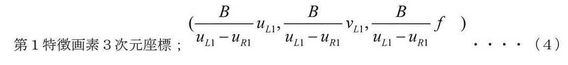


本ステップ230において、導出部112は、数式(4)~(6)に示す第1~第3特徴画素3次元座標の各々を数式(3)に代入して得られる等価関係にある3つの数式から数式(3)のa,b,cを最適化することで、数式(3)のa,b,cを導出する。このように、数式(3)のa,b,cが導出されるということは、数式(3)に示す平面方程式により規定される平面の向きが導出されることを意味する。
In step 230, the derivation unit 112 has three mathematical expressions in an equivalent relationship obtained by substituting each of the first to third feature pixel three-dimensional coordinates shown in the mathematical expressions (4) to (6) into the mathematical expression (3). By optimizing a, b, and c in Equation (3), a, b, and c in Equation (3) are derived. Thus, a, b, and c in Equation (3) being derived means that the orientation of the plane defined by the plane equation shown in Equation (3) is derived.
ステップ232で、導出部112は、ステップ214の処理で導出した照射位置座標に基づいて数式(3)に示す平面方程式を確定し、その後、ステップ234へ移行する。すなわち、本ステップ232において、導出部112は、ステップ230の処理で導出したa,b,c及びステップ214の処理で導出した照射位置座標を数式(3)に代入することで、数式(3)のdを確定する。ステップ230の処理で数式(3)のa,b,cが導出されているので、本ステップ232の処理で数式(3)のdが確定されると、数式(3)に示す平面方程式が確定される。
In step 232, the deriving unit 112 determines the plane equation shown in the mathematical expression (3) based on the irradiation position coordinates derived in the process of step 214, and then proceeds to step 234. In other words, in step 232, the derivation unit 112 substitutes the a, b, c derived in the process of step 230 and the irradiation position coordinates derived in the process of step 214 into the formula (3), thereby obtaining the formula (3). Of d. Since a, b, and c in Expression (3) are derived in the process of Step 230, when d in Expression (3) is determined in the process of Step 232, the plane equation shown in Expression (3) is determined. Is done.
ステップ234で、導出部112は、注目画素座標、対応注目画素座標、撮像レンズ50の焦点距離、撮像画素60A1の寸法、平面方程式、及び数式(1)に基づいて、撮像位置距離を算出し、その後、ステップ236へ移行する。
In step 234, the derivation unit 112 calculates the imaging position distance based on the target pixel coordinates, the corresponding target pixel coordinates, the focal length of the imaging lens 50, the dimensions of the imaging pixel 60A1, the plane equation, and the formula (1). Thereafter, the process proceeds to step 236.
ここで、本ステップ234の処理で用いられる注目画素座標とは、ステップ210の処理で取得された注目画素座標を指す。また、本ステップ234の処理で用いられる対応注目画素座標とは、ステップ226の処理で取得された対応注目画素座標を指す。更に、本ステップ234で用いられる平面方程式とは、ステップ232で確定された平面方程式を指す。
Here, the pixel-of-interest coordinates used in the process of step 234 indicate the pixel-of-interest coordinates acquired in the process of step 210. Further, the corresponding target pixel coordinates used in the process of step 234 indicate the corresponding target pixel coordinates acquired in step 226. Further, the plane equation used in step 234 indicates the plane equation determined in step 232.
よって、本ステップ234では、注目画素座標、対応注目画素座標、撮像レンズ50の焦点距離、及び撮像画素60A1の寸法が代入された数式(1)の(X,Y,Z)が平面方程式に代入されることで、撮像位置距離である“B”が算出される。
Therefore, in this step 234, (X, Y, Z) in Expression (1) into which the target pixel coordinates, the corresponding target pixel coordinates, the focal length of the imaging lens 50, and the dimensions of the imaging pixel 60A1 are substituted is substituted into the plane equation. As a result, “B” that is the imaging position distance is calculated.
なお、撮像位置距離である“B”は、特徴画素3次元座標とステップ232で確定された平面方程式とに基づいて導出されるようにしてもよい。すなわち、この場合、撮像位置距離である“B”は、ステップ232で確定された平面方程式に特徴画素3次元座標が代入されることによって導出される。ここで言う「特徴画素3次元座標」とは、例えば、第1特徴画素3次元座標を指すが、これに限らず、第2特徴画素3次元座標又は第3特徴画素3次元座標であってもよい。
Note that “B” as the imaging position distance may be derived based on the three-dimensional feature pixel coordinates and the plane equation determined in step 232. That is, in this case, “B” that is the imaging position distance is derived by substituting the feature pixel three-dimensional coordinates into the plane equation determined in step 232. The “feature pixel three-dimensional coordinate” referred to here refers to, for example, the first feature pixel three-dimensional coordinate, but is not limited thereto, and may be the second feature pixel three-dimensional coordinate or the third feature pixel three-dimensional coordinate. Good.
ステップ236で、制御部114は、一例として図17に示すように、表示部86に対して、ステップ234の処理で算出された撮像位置距離を第2撮像画像に重畳して表示させる。また、ステップ236で、制御部114は、ステップ234の処理で算出された撮像位置距離を既定の記憶領域に記憶し、その後、本撮像位置距離算出処理を終了する。なお、既定の記憶領域の一例としては、一次記憶部102の記憶領域又は二次記憶部104の記憶領域が挙げられる。
In step 236, as shown in FIG. 17 as an example, the control unit 114 causes the display unit 86 to display the imaging position distance calculated in the process of step 234 superimposed on the second captured image. In step 236, the control unit 114 stores the imaging position distance calculated in step 234 in a predetermined storage area, and then ends the main imaging position distance calculation process. Note that examples of the default storage area include a storage area of the primary storage unit 102 or a storage area of the secondary storage unit 104.
なお、図17に示す例では、「144656.1」との数値が、ステップ234の処理で算出された撮像位置距離に該当し、単位はミリメートルである。
In the example shown in FIG. 17, the numerical value “144656.1” corresponds to the imaging position distance calculated by the processing in step 234, and the unit is millimeters.
次に、3次元座標算出ボタン90Gがオンされた場合にCPU100が3次元座標算出プログラム108を実行することで実現される3次元座標算出処理について図18を参照して説明する。
Next, a three-dimensional coordinate calculation process realized by the CPU 100 executing the three-dimensional coordinate calculation program 108 when the three-dimensional coordinate calculation button 90G is turned on will be described with reference to FIG.
図18に示す3次元座標算出処理では、先ず、ステップ250で、導出部112は、撮像位置距離算出処理に含まれるステップ234の処理で撮像位置距離が既に算出されているか否かを判定する。ステップ250において、撮像位置距離算出処理に含まれるステップ234の処理で撮像位置距離が算出されていない場合は、判定が否定されて、ステップ258へ移行する。ステップ250において、撮像位置距離算出処理に含まれるステップ234の処理で撮像位置距離が既に算出されている場合は、判定が肯定されて、ステップ252へ移行する。
In the three-dimensional coordinate calculation process shown in FIG. 18, first, in step 250, the derivation unit 112 determines whether or not the imaging position distance has already been calculated in the process of step 234 included in the imaging position distance calculation process. In step 250, when the imaging position distance is not calculated in the process of step 234 included in the imaging position distance calculation process, the determination is negative and the process proceeds to step 258. In step 250, when the imaging position distance has already been calculated in the process of step 234 included in the imaging position distance calculation process, the determination is affirmed and the process proceeds to step 252.
ステップ252で、導出部112は、指定画素3次元座標の算出を開始する条件(以下、「算出開始条件」という)を満足したか否かを判定する。算出開始条件の一例としては、指定画素3次元座標の算出を開始する指示がタッチパネル88によって受け付けられたとの条件や、撮像位置距離が表示部86に表示されたとの条件等が挙げられる。
In step 252, the deriving unit 112 determines whether or not a condition for starting calculation of the designated pixel three-dimensional coordinates (hereinafter referred to as “calculation start condition”) is satisfied. Examples of the calculation start condition include a condition that an instruction to start calculation of designated pixel three-dimensional coordinates is received by the touch panel 88, a condition that an imaging position distance is displayed on the display unit 86, and the like.
ステップ252において、算出開始条件を満足していない場合は、判定が否定されて、ステップ258へ移行する。ステップ252において、算出開始条件を満足した場合は、判定が肯定されて、ステップ254へ移行する。
If the calculation start condition is not satisfied in step 252, the determination is denied and the process proceeds to step 258. If the calculation start condition is satisfied in step 252, the determination is affirmed and the process proceeds to step 254.
ステップ254で、導出部112は、注目画素座標、対応注目画素座標、撮像位置距離、撮像レンズ50の焦点距離、撮像画素60A1の寸法、及び数式(1)に基づいて、指定画素3次元座標を算出し、その後、ステップ256へ移行する。
In step 254, the deriving unit 112 calculates the designated pixel three-dimensional coordinates based on the target pixel coordinates, the corresponding target pixel coordinates, the imaging position distance, the focal length of the imaging lens 50, the dimensions of the imaging pixel 60A1, and the mathematical expression (1). Then, the process proceeds to step 256.
ここで、本ステップ254の処理で用いられる注目画素座標とは、撮像位置距離算出処理に含まれるステップ210の処理で取得された注目画素座標を指す。また、本ステップ254の処理で用いられる対応注目画素座標とは、撮像位置距離算出処理に含まれるステップ226の処理で取得された対応注目画素座標を指す。また、本ステップ254の処理で用いられる撮像位置距離とは、撮像位置距離算出処理に含まれるステップ234の処理で導出された撮像位置距離を指す。
Here, the target pixel coordinates used in the process of step 254 indicate the target pixel coordinates acquired by the process of step 210 included in the imaging position distance calculation process. Further, the corresponding target pixel coordinates used in the process of step 254 indicate the corresponding target pixel coordinates acquired by the process of step 226 included in the imaging position distance calculation process. Further, the imaging position distance used in the process of step 254 indicates the imaging position distance derived by the process of step 234 included in the imaging position distance calculation process.
よって、本ステップ254では、注目画素座標、対応注目画素座標、撮像位置距離、撮像レンズ50の焦点距離、及び撮像画素60A1の寸法が数式(1)に代入されることで、指定画素3次元座標が算出される。
Therefore, in step 254, the target pixel coordinates, the corresponding target pixel coordinates, the imaging position distance, the focal length of the imaging lens 50, and the dimensions of the imaging pixel 60A1 are substituted into the mathematical formula (1), thereby specifying the designated pixel three-dimensional coordinates. Is calculated.
ステップ256で、制御部114は、一例として図19に示すように、表示部86に対して、ステップ254の処理で算出された指定画素3次元座標を第2撮像画像に重畳して表示させる。また、ステップ256で、制御部114は、ステップ254の処理で算出された指定画素3次元座標を既定の記憶領域に記憶し、その後、本3次元座標算出処理を終了する。なお、既定の記憶領域の一例としては、一次記憶部102の記憶領域又は二次記憶部104の記憶領域が挙げられる。
In step 256, as shown in FIG. 19 as an example, the control unit 114 causes the display unit 86 to display the designated pixel three-dimensional coordinates calculated in the process of step 254 superimposed on the second captured image. In step 256, the control unit 114 stores the designated pixel three-dimensional coordinates calculated in step 254 in a predetermined storage area, and thereafter ends the three-dimensional coordinate calculation process. Note that examples of the default storage area include a storage area of the primary storage unit 102 or a storage area of the secondary storage unit 104.
なお、図19に示す例では、(20161,50134,136892)が、ステップ254の処理で算出された指定画素3次元座標に該当する。また、図19に示す例では、指定画素3次元座標が注目画素126に近接して表示されている。なお、注目画素126は、他の画素と区別可能に強調表示されるようにしてもよい。
In the example shown in FIG. 19, (20161, 50134, 136892) corresponds to the designated pixel three-dimensional coordinates calculated in the process of step 254. In the example shown in FIG. 19, the designated pixel three-dimensional coordinates are displayed close to the target pixel 126. Note that the target pixel 126 may be highlighted so as to be distinguishable from other pixels.
ステップ258で、導出部112は、3次元座標算出処理を終了する条件を満足したか否かを判定する。3次元座標算出処理を終了する条件の一例としては、タッチパネル88により3次元座標算出処理を終了する指示が受け付けられたとの条件が挙げられる。3次元座標算出処理を終了する条件の他の例としては、ステップ250で判定が否定されてからステップ250で判定が肯定されることなく第2既定時間が経過したとの条件等が挙げられる。なお、第2既定時間とは、例えば、30分を指す。
In step 258, the deriving unit 112 determines whether or not a condition for ending the three-dimensional coordinate calculation process is satisfied. An example of a condition for ending the three-dimensional coordinate calculation process is a condition that an instruction to end the three-dimensional coordinate calculation process is received from the touch panel 88. Another example of the condition for ending the three-dimensional coordinate calculation process includes a condition that the second predetermined time has passed without the determination being affirmed in Step 250 after the determination in Step 250 was denied. The second predetermined time refers to, for example, 30 minutes.
ステップ258において、本3次元座標算出処理を終了する条件を満足していない場合は、判定が否定されて、ステップ250へ移行する。ステップ258において、本3次元座標算出処理を終了する条件を満足した場合は、判定が肯定されて、本3次元座標算出処理を終了する。
If it is determined in step 258 that the conditions for ending the three-dimensional coordinate calculation process are not satisfied, the determination is negative and the process proceeds to step 250. In step 258, if the condition for ending the three-dimensional coordinate calculation process is satisfied, the determination is affirmed and the three-dimensional coordinate calculation process is ended.
以上説明したように、測距装置10Aでは、取得部110により、第1撮像画像、第2撮像画像、及び被写体までの距離が取得される。また、ユーザによりタッチパネル88を介して第1撮像画像において注目画素126が指定され、取得部110により注目画素座標が取得される(ステップ210)。また、取得部110により対応注目画素座標が取得される(ステップ226)。また、取得部110により3特徴画素座標が取得される(ステップ212)。また、取得部110により対応特徴画素座標が取得される(ステップ228)。また、導出部112により照射位置座標が算出される(ステップ214)。そして、導出部112により、注目画素座標、対応注目画素座標、3特徴画素座標、対応特徴画素座標、照射位置座標、撮像レンズ50の焦点距離、及び撮像画素60A1の寸法に基づいて、撮像位置距離が導出される。
As described above, in the distance measuring device 10A, the acquisition unit 110 acquires the first captured image, the second captured image, and the distance to the subject. Further, the target pixel 126 is designated in the first captured image by the user via the touch panel 88, and the target pixel coordinates are acquired by the acquisition unit 110 (step 210). Further, the corresponding attention pixel coordinates are acquired by the acquisition unit 110 (step 226). Further, the three feature pixel coordinates are acquired by the acquisition unit 110 (step 212). Further, the corresponding feature pixel coordinates are acquired by the acquisition unit 110 (step 228). Further, the irradiation position coordinates are calculated by the deriving unit 112 (step 214). The deriving unit 112 then captures the imaging position distance based on the target pixel coordinates, the corresponding target pixel coordinates, the three feature pixel coordinates, the corresponding feature pixel coordinates, the irradiation position coordinates, the focal length of the imaging lens 50, and the dimensions of the imaging pixel 60A1. Is derived.
従って、測距装置10Aによれば、特定可能な特徴的な箇所にレーザ光が照射されない場合であっても、被写体が第1撮像位置及び第2撮像位置の各々から撮像されて得られた第1撮像画像及び第2撮像画像に基づいて撮像位置距離を導出することができる。
Therefore, according to the distance measuring device 10A, even when the identifiable characteristic portion is not irradiated with the laser beam, the subject is captured from each of the first imaging position and the second imaging position. The imaging position distance can be derived based on the first captured image and the second captured image.
また、測距装置10Aでは、撮像位置距離算出処理で算出された撮像位置距離に基づいて、指定画素3次元座標が算出される(図18参照)。従って、測距装置10Aによれば、特定可能な特徴的な箇所にレーザ光が照射されない場合であっても、指定画素3次元座標を導出することができる。
In the distance measuring apparatus 10A, the designated pixel three-dimensional coordinates are calculated based on the imaging position distance calculated in the imaging position distance calculation process (see FIG. 18). Therefore, according to the distance measuring device 10 </ b> A, the designated pixel three-dimensional coordinates can be derived even when the identifiable characteristic portion is not irradiated with the laser beam.
また、測距装置10Aでは、指定画素3次元座標は、注目画素座標、対応注目画素座標、撮像位置距離、撮像レンズ50の焦点距離、及び撮像画素60A1の寸法に基づいて規定されている(数式(1)参照)。従って、測距装置10Aによれば、指定画素3次元座標が注目画素座標、対応注目画素座標、撮像位置距離、撮像レンズ50の焦点距離、及び撮像画素60A1の寸法に基づいて規定されない場合に比べ、指定画素3次元座標を高精度に導出することができる。
In the distance measuring device 10A, the designated pixel three-dimensional coordinates are defined based on the target pixel coordinates, the corresponding target pixel coordinates, the imaging position distance, the focal length of the imaging lens 50, and the dimensions of the imaging pixel 60A1 (formulas). (See (1)). Therefore, according to the distance measuring device 10A, the designated pixel three-dimensional coordinates are not defined based on the target pixel coordinates, the corresponding target pixel coordinates, the imaging position distance, the focal length of the imaging lens 50, and the dimensions of the imaging pixel 60A1. The designated pixel three-dimensional coordinates can be derived with high accuracy.
また、測距装置10Aでは、導出部112により、3特徴画素座標、対応特徴画素座標、撮像レンズ50の焦点距離、及び撮像画素60A1の寸法に基づいて、数式(3)に示す平面方程式により規定される平面の向きが導出される(ステップ230)。また、導出部112により、平面の向きとステップ214の処理で算出された照射位置座標とに基づいて数式(3)に示す平面方程式が確定される(ステップ232)。そして、導出部112により、確定された平面方程式、注目画素座標、撮像レンズ50の焦点距離、及び撮像画素60A1の寸法に基づいて撮像位置距離が算出される(ステップ234)。従って、測距装置10Aによれば、特定可能な特徴的な箇所にレーザ光が照射されない場合に平面方程式を用いずに撮像位置距離を導出する場合に比べ、撮像位置距離を高精度に導出することができる。
Further, in the distance measuring device 10A, the deriving unit 112 defines the three feature pixel coordinates, the corresponding feature pixel coordinates, the focal length of the imaging lens 50, and the dimensions of the imaging pixel 60A1 by the plane equation shown in Equation (3). The orientation of the plane to be performed is derived (step 230). Also, the plane equation shown in Formula (3) is determined by the deriving unit 112 based on the orientation of the plane and the irradiation position coordinates calculated in the process of Step 214 (Step 232). Then, the imaging position distance is calculated by the deriving unit 112 based on the determined plane equation, the target pixel coordinates, the focal length of the imaging lens 50, and the dimensions of the imaging pixel 60A1 (step 234). Therefore, according to the distance measuring apparatus 10A, the imaging position distance is derived with higher accuracy than when the imaging position distance is derived without using the plane equation when the laser beam is not irradiated to the identifiable characteristic portion. be able to.
また、測距装置10Aでは、取得部110により3特徴画素座標が取得され(ステップ212)、取得部110により対応特徴画素座標が取得される(ステップ228)。そして、導出部112により、注目画素座標、対応注目画素座標、3特徴画素座標、対応特徴画素座標、照射位置座標、撮像レンズ50の焦点距離、及び撮像画素60A1の寸法に基づいて撮像位置距離が算出される(ステップ230~234)。従って、測距装置10Aによれば、3特徴画素座標及び対応特徴画素座標を取得するにあたって特徴的な3画素をユーザに指定させる場合に比べ、少ない操作数で、3特徴画素座標及び対応特徴画素座標を基に撮像位置距離を導出することができる。
In the distance measuring apparatus 10A, the acquisition unit 110 acquires three feature pixel coordinates (step 212), and the acquisition unit 110 acquires corresponding feature pixel coordinates (step 228). The deriving unit 112 then calculates the imaging position distance based on the target pixel coordinates, the corresponding target pixel coordinates, the three feature pixel coordinates, the corresponding feature pixel coordinates, the irradiation position coordinates, the focal length of the imaging lens 50, and the dimensions of the imaging pixel 60A1. Calculated (steps 230 to 234). Therefore, according to the distance measuring device 10A, the three feature pixel coordinates and the corresponding feature pixels are reduced in the number of operations compared to the case where the user designates the three characteristic pixel coordinates when acquiring the three feature pixel coordinates and the corresponding feature pixel coordinates. The imaging position distance can be derived based on the coordinates.
また、測距装置10Aでは、画素指定情報がタッチパネル88によって受け付けられ、受け付けられた画素指定情報により指定された画素が注目画素126とされ、取得部110により、注目画素座標が取得される(ステップ210)。また、取得部110により、注目画素126に対応する画素である対応注目画素が特定される。そして、取得部110により、対応画素注目画素を特定する対応注目画素座標が取得される(ステップ226)。従って、測距装置10Aによれば、第1撮像画像及び第2撮像画像の両方に関する指定画素がユーザにより指定される場合に比べ、第1撮像画像及び第2撮像画像の両方に関する指定画素を迅速に決めることができる。
In the distance measuring device 10A, the pixel designation information is received by the touch panel 88, the pixel designated by the accepted pixel designation information is set as the target pixel 126, and the target pixel coordinates are acquired by the acquisition unit 110 (Step S1). 210). In addition, the acquisition unit 110 identifies a corresponding target pixel that is a pixel corresponding to the target pixel 126. And the corresponding attention pixel coordinate which specifies a corresponding pixel attention pixel is acquired by the acquisition part 110 (step 226). Therefore, according to the distance measuring device 10A, the designated pixels related to both the first captured image and the second captured image are quickly compared with the case where the designated pixels related to both the first captured image and the second captured image are specified by the user. Can be decided.
また、測距装置10Aには、測距ユニット12及び測距制御部68が含まれ、測距ユニット12及び測距制御部68によって計測された被写体までの距離が取得部110により取得される。従って、測距装置10Aによれば、測距ユニット12及び測距制御部68を有しない場合に比べ、照射位置座標の導出に用いる被写体までの距離を容易に取得することができる。
The distance measuring device 10A includes a distance measuring unit 12 and a distance measurement control unit 68, and the distance to the subject measured by the distance measurement unit 12 and the distance measurement control unit 68 is acquired by the acquisition unit 110. Therefore, according to the distance measuring apparatus 10A, the distance to the subject used for deriving the irradiation position coordinates can be easily obtained as compared with the case where the distance measuring unit 12 and the distance measuring control unit 68 are not provided.
また、測距装置10Aには、撮像装置14が含まれ、撮像装置14により被写体が撮像されて得られた第1撮像画像及び第2撮像画像が取得部110により取得される。従って、測距装置10Aによれば、撮像装置14を有しない場合に比べ、注目画素座標、3特徴画素座標、対応注目画素座標、及び対応特徴画素座標を得るために用いる第1撮像画像及び第2撮像画像を容易に取得することができる。
Further, the distance measuring device 10A includes the imaging device 14, and the acquisition unit 110 acquires the first captured image and the second captured image obtained by imaging the subject by the imaging device 14. Therefore, according to the distance measuring device 10A, compared with the case where the imaging device 14 is not provided, the first captured image and the first captured image used to obtain the target pixel coordinates, the three feature pixel coordinates, the corresponding target pixel coordinates, and the corresponding feature pixel coordinates. Two captured images can be easily acquired.
更に、測距装置10Aでは、導出部112による導出結果が表示部86によって表示される。従って、測距装置10Aによれば、導出部112による導出結果が表示部86によって表示されない場合に比べ、導出部112による導出結果をユーザに容易に認識させることができる。
Furthermore, in the distance measuring device 10A, the derivation result by the derivation unit 112 is displayed on the display unit 86. Therefore, according to the distance measuring apparatus 10 </ b> A, the derivation result obtained by the derivation unit 112 can be easily recognized by the user as compared with the case where the derivation result obtained by the derivation unit 112 is not displayed by the display unit 86.
なお、上記第1実施形態では、3特徴画素座標を例示したが、本開示の技術はこれに限定されるものでない。例えば、3特徴画素座標に代えて、特徴的な4画素以上の既定数の画素の各々を特定する2次元座標を採用してもよい。
In the first embodiment, three feature pixel coordinates are exemplified, but the technology of the present disclosure is not limited to this. For example, instead of the three characteristic pixel coordinates, two-dimensional coordinates that specify each of a predetermined number of characteristic four or more pixels may be adopted.
また、上記第1実施形態では、注目画素座標が第1撮像画像上の座標から取得され、対応注目画素座標が第2撮像画像上の座標から取得される場合を例示したが、本開示の技術はこれに限定されるものではない。例えば、注目画素座標が第2撮像画像上の座標から取得され、対応注目画素座標が第1撮像画像上の座標から取得されるようにしてもよい。
In the first embodiment, the case where the pixel-of-interest coordinates are acquired from the coordinates on the first captured image and the corresponding pixel-of-interest coordinates are acquired from the coordinates on the second captured image is exemplified. Is not limited to this. For example, the target pixel coordinates may be acquired from the coordinates on the second captured image, and the corresponding target pixel coordinates may be acquired from the coordinates on the first captured image.
また、上記第1実施形態では、3特徴画素座標が第1撮像画像上の座標から取得され、対応特徴画素座標が第2撮像画像上の座標から取得される場合を例示したが、本開示の技術はこれに限定されるものではない。例えば、3特徴画素座標が第2撮像画像上の座標から取得され、対応特徴画素座標が第1撮像画像上の座標から取得されるようにしてもよい。
In the first embodiment, the case where the three feature pixel coordinates are acquired from the coordinates on the first captured image and the corresponding feature pixel coordinates are acquired from the coordinates on the second captured image is illustrated. The technology is not limited to this. For example, three feature pixel coordinates may be acquired from coordinates on the second captured image, and corresponding feature pixel coordinates may be acquired from coordinates on the first captured image.
また、上記第1実施形態では、3特徴画素座標として、第1画素130、第2画素132、及び第3画素134の各々を特定する2次元座標が取得部110によって取得される場合を例示したが、本開示の技術はこれに限定されるものではない。例えば、図20に示すように、第1画素130A、第2画素132A、及び第3画素134Aの各々を特定する2次元座標が取得部110によって取得されるようにしてもよい。第1画素130A、第2画素132A、及び第3画素134Aは、外壁面画像128において取り囲まれる面積が最大となる3画素である。なお、3画素に限らず、外壁面画像128において取り囲まれる面積が最大となる3画素以上の既定数の画素であればよい。
In the first embodiment, the case where the acquisition unit 110 acquires two-dimensional coordinates specifying each of the first pixel 130, the second pixel 132, and the third pixel 134 as the three characteristic pixel coordinates is illustrated. However, the technology of the present disclosure is not limited to this. For example, as illustrated in FIG. 20, two-dimensional coordinates that specify each of the first pixel 130 </ b> A, the second pixel 132 </ b> A, and the third pixel 134 </ b> A may be acquired by the acquisition unit 110. The first pixel 130 </ b> A, the second pixel 132 </ b> A, and the third pixel 134 </ b> A are three pixels that have the maximum area surrounded by the outer wall surface image 128. Note that the number of pixels is not limited to three pixels, but may be a predetermined number of pixels that is three or more pixels that maximizes the area surrounded by the outer wall surface image 128.
このように、図20に示す例では、外壁面画像128において取り囲まれる面積が最大となる3画素が特徴的な3画素として特定され、特定された3画素に関する2次元座標が3特徴画素座標として取得部110によって取得される。また、取得部110により、3特徴画素座標に対応する対応特徴画素座標も取得される。従って、測距装置10Aによれば、特徴的な3画素として、取り囲む面積が最大とならない複数の画素を特定する3特徴画素座標及び対応特徴画素座標が取得される場合に比べ、撮像位置距離を高精度に導出することができる。
As described above, in the example illustrated in FIG. 20, the three pixels having the maximum area surrounded by the outer wall surface image 128 are specified as the characteristic three pixels, and the two-dimensional coordinates relating to the specified three pixels are the three characteristic pixel coordinates. Acquired by the acquisition unit 110. The acquisition unit 110 also acquires corresponding feature pixel coordinates corresponding to the three feature pixel coordinates. Therefore, according to the distance measuring device 10A, as compared with the case where three characteristic pixel coordinates and corresponding characteristic pixel coordinates that specify a plurality of pixels whose surrounding area is not the maximum are acquired as characteristic three pixels, the imaging position distance is set. It can be derived with high accuracy.
また、上記第1実施形態では、3次元座標算出ボタン90Gがオンされた場合に撮像位置距離導出処理が実現される場合について説明したが、本発明はこれに限定されるものではない。例えば、撮像位置距離算出ボタン90Fがオンされた場合に撮像位置距離導出処理が実行されるようにしてもよい。上記第1実施形態で説明した撮像位置距離導出処理は、3次元座標の導出を最終的な目的とした場合の一例である。
In the first embodiment, the case where the imaging position distance deriving process is realized when the three-dimensional coordinate calculation button 90G is turned on has been described, but the present invention is not limited to this. For example, the imaging position distance derivation process may be executed when the imaging position distance calculation button 90F is turned on. The imaging position distance deriving process described in the first embodiment is an example in the case where the ultimate purpose is to derive three-dimensional coordinates.
そのため、3次元座標の導出で要する注目画素座標及び対応画素座標を撮像位置距離導出処理で取得しているが、撮像位置距離の導出のみが目的の場合、撮像位置距離導出処理での注目画素座標及び対応画素座標の取得は不要である。よって、CPU100は、撮像位置距離算出ボタン90Fがオンされた場合、注目画素座標及び対応注目画素座標を取得せずに撮像位置距離を導出し、次いで、3次元座標算出ボタン90Gがオンされた場合に、注目画素座標及び対応注目画素座標を取得してもよい。この場合、CPU100は、例えば、図34に示す3次元座標導出処理のステップ252の処理とステップ254の処理との間で注目画素座標及び対応注目画素座標を取得し、取得した注目画素座標及び対応注目画素座標をステップ254の処理で用いればよい。
Therefore, the target pixel coordinates and corresponding pixel coordinates required for derivation of the three-dimensional coordinates are acquired by the imaging position distance derivation process, but when only the imaging position distance is derived, the target pixel coordinates in the imaging position distance derivation process are obtained. And acquisition of corresponding pixel coordinates is unnecessary. Therefore, when the imaging position distance calculation button 90F is turned on, the CPU 100 derives the imaging position distance without acquiring the target pixel coordinates and the corresponding target pixel coordinates, and then when the three-dimensional coordinate calculation button 90G is turned on. In addition, the target pixel coordinates and the corresponding target pixel coordinates may be acquired. In this case, for example, the CPU 100 acquires the target pixel coordinates and the corresponding target pixel coordinates between the processing in step 252 and the processing in step 254 of the three-dimensional coordinate derivation processing illustrated in FIG. The pixel coordinates of interest may be used in the process of step 254.
[第2実施形態]
上記第1実施形態では、外壁面画像128の全体を対象として3特徴画素座標が取得される場合について説明したが、本第2実施形態では、外壁面画像128の一部を対象として3特徴画素座標が取得される場合について説明する。なお、本第2実施形態では、上記第1実施形態で説明した構成要素と同一の構成要素については同一の符号を付し、その説明を省略する。 [Second Embodiment]
In the first embodiment, the case where the three feature pixel coordinates are acquired for the entireouter wall image 128 has been described. However, in the second embodiment, the three feature pixels are used for a part of the outer wall image 128. A case where coordinates are acquired will be described. In the second embodiment, the same components as those described in the first embodiment are denoted by the same reference numerals, and the description thereof is omitted.
上記第1実施形態では、外壁面画像128の全体を対象として3特徴画素座標が取得される場合について説明したが、本第2実施形態では、外壁面画像128の一部を対象として3特徴画素座標が取得される場合について説明する。なお、本第2実施形態では、上記第1実施形態で説明した構成要素と同一の構成要素については同一の符号を付し、その説明を省略する。 [Second Embodiment]
In the first embodiment, the case where the three feature pixel coordinates are acquired for the entire
本第2実施形態に係る測距装置10Bは、一例として図6に示すように、測距装置10Aに比べ、二次記憶部104に撮像位置距離算出プログラム106に代えて撮像位置距離算出プログラム150が記憶されている点が異なる。
As shown in FIG. 6 as an example, the distance measuring device 10B according to the second embodiment has an imaging position distance calculation program 150 in the secondary storage unit 104 instead of the imaging position distance calculation program 106, as compared with the distance measuring device 10A. Is different in that is stored.
CPU100は、撮像位置距離算出プログラム150及び3次元座標算出プログラム108を実行することで、取得部154、導出部112、並びに、本開示の技術に係る第1制御部及び第2制御部の一例である制御部156として動作する(図9参照)。
The CPU 100 is an example of the acquisition unit 154, the derivation unit 112, and the first control unit and the second control unit according to the technique of the present disclosure by executing the imaging position distance calculation program 150 and the three-dimensional coordinate calculation program 108. It operates as a certain control unit 156 (see FIG. 9).
取得部154は、上記第1実施形態で説明した取得部110に対応し、制御部156は、上記第1実施形態で説明した制御部114に対応する。なお、本第2実施形態では、説明の便宜上、取得部154及び制御部156については、上記第1実施形態で説明した取得部110及び制御部114と異なる部分について説明する。
The acquisition unit 154 corresponds to the acquisition unit 110 described in the first embodiment, and the control unit 156 corresponds to the control unit 114 described in the first embodiment. In the second embodiment, for the sake of convenience, the acquisition unit 154 and the control unit 156 will be described with respect to differences from the acquisition unit 110 and the control unit 114 described in the first embodiment.
制御部156は、表示部86に対して第1撮像画像を表示させ、かつ、表示領域内で本開示の技術に係る対応領域の一例である外壁面画像128を他の領域と区別可能に表示させる制御を行う。タッチパネル88は、表示部86に外壁面画像128が表示された状態で座標取得対象領域158(図22参照)を指定する領域指定情報を受け付ける。ここで、座標取得対象領域158とは、外壁面画像128のうちの一部の閉領域を指す。領域指定情報とは、座標取得対象領域158を指定する情報を指す。
The control unit 156 displays the first captured image on the display unit 86, and displays the outer wall surface image 128, which is an example of the corresponding region according to the technology of the present disclosure, in the display region so as to be distinguishable from other regions. To control. The touch panel 88 receives region designation information for designating the coordinate acquisition target region 158 (see FIG. 22) in a state where the outer wall surface image 128 is displayed on the display unit 86. Here, the coordinate acquisition target region 158 indicates a part of the closed region of the outer wall surface image 128. The area designation information refers to information that designates the coordinate acquisition target area 158.
取得部154は、タッチパネル88によって受け付けられた領域指定情報により指定された座標取得対象領域158から、3特徴画素座標を取得する。
The acquisition unit 154 acquires the three characteristic pixel coordinates from the coordinate acquisition target area 158 specified by the area specification information received by the touch panel 88.
次に、測距装置10Bの本開示の技術に係る部分の作用として、CPU100が撮像位置距離算出プログラム150を実行することで実現される撮像位置距離算出処理について図21を参照して説明する。なお、図11に示すフローチャートと同一のステップについては、同一のステップ番号を付して、その説明を省略する。
Next, an imaging position distance calculation process realized by the CPU 100 executing the imaging position distance calculation program 150 will be described with reference to FIG. 21 as an operation of the portion related to the technology of the present disclosure of the distance measuring device 10B. Note that the same steps as those in the flowchart shown in FIG. 11 are denoted by the same step numbers, and the description thereof is omitted.
図21に示すフローチャートは、図11に示すフローチャートに比べ、ステップ212に代えて、ステップ300~312を有する点が異なる。
The flowchart shown in FIG. 21 is different from the flowchart shown in FIG. 11 in that steps 300 to 312 are provided instead of step 212.
図21に示すステップ300で、制御部156は、第1撮像画像から外壁面画像128(図15参照)を特定し、その後、ステップ302へ移行する。
In step 300 shown in FIG. 21, the control unit 156 identifies the outer wall surface image 128 (see FIG. 15) from the first captured image, and then proceeds to step 302.
ステップ302で、制御部156は、表示部86に対して、ステップ300の処理で特定した外壁面画像128を、第1撮像画像の表示領域内の他の領域と区別可能に強調して表示させ、その後、ステップ304へ移行する。
In step 302, the control unit 156 causes the display unit 86 to display the outer wall surface image 128 identified in the process of step 300 in a highlighted manner so as to be distinguishable from other regions in the display region of the first captured image. Thereafter, the process proceeds to step 304.
ステップ304で、取得部154は、タッチパネル88によって領域指定情報が受け付けられ、受け付けられた領域指定情報により座標取得対象領域158が指定されたか否かを判定する。
In step 304, the acquisition unit 154 determines whether or not the area designation information has been received by the touch panel 88 and the coordinate acquisition target area 158 has been designated by the received area designation information.
ステップ304において、領域指定情報により座標取得対象領域158が指定されていない場合は、判定が否定されて、ステップ306へ移行する。ステップ304において、領域指定情報により座標取得対象領域158が指定された場合は、判定が肯定されて、ステップ308へ移行する。
In step 304, if the coordinate acquisition target area 158 is not designated by the area designation information, the determination is denied and the process proceeds to step 306. If the coordinate acquisition target area 158 is designated by the area designation information in step 304, the determination is affirmed and the routine proceeds to step 308.
ステップ306で、取得部154は、本撮像位置距離算出処理を終了する条件を満足したか否かを判定する。ステップ306において、本撮像位置距離算出処理を終了する条件を満足していない場合は、判定が否定されて、ステップ304へ移行する。ステップ306において、本撮像位置距離算出処理を終了する条件を満足した場合は、判定が肯定されて、本撮像位置距離算出処理を終了する。
In step 306, the acquisition unit 154 determines whether or not a condition for terminating the imaging position distance calculation process is satisfied. If it is determined in step 306 that the conditions for ending the actual imaging position distance calculation process are not satisfied, the determination is negative and the routine proceeds to step 304. In step 306, when the condition for ending the actual imaging position distance calculation process is satisfied, the determination is affirmed, and the actual imaging position distance calculation process ends.
ステップ308で、取得部154は、タッチパネル88によって受け付けられた領域指定情報により指定された座標取得対象領域158に、上記第1実施形態で説明した特徴的な3画素が存在するか否かを判定する。
In step 308, the acquisition unit 154 determines whether the characteristic three pixels described in the first embodiment exist in the coordinate acquisition target area 158 specified by the area specification information received by the touch panel 88. To do.
一例として図22に示すように、タッチパネル88によって受け付けられた領域指定情報により座標取得対象領域158が指定された場合、座標取得対象領域158には、模様124(図13参照)を示す模様画像160が含まれている。
As an example, as illustrated in FIG. 22, when the coordinate acquisition target region 158 is specified by the region specification information received by the touch panel 88, the pattern acquisition image 160 indicating the pattern 124 (see FIG. 13) is displayed in the coordinate acquisition target region 158. It is included.
図23に示す例では、座標取得対象領域158に、特徴的な3画素として、第1画素162、第2画素164、及び第3画素166が含まれている。図23に示す例において、第1画素162は、模様画像160の正面視左上隅の画素であり、第2画素164は、模様画像160の正面視左下隅の画素であり、第3画素166は、模様画像160の正面視右下隅の画素である。
In the example shown in FIG. 23, the coordinate acquisition target area 158 includes a first pixel 162, a second pixel 164, and a third pixel 166 as characteristic three pixels. In the example shown in FIG. 23, the first pixel 162 is a pixel at the upper left corner of the pattern image 160 when viewed from the front, the second pixel 164 is a pixel at the lower left corner of the pattern image 160 when viewed from the front, and the third pixel 166 is , The pixel at the lower right corner of the pattern image 160 when viewed from the front.
ステップ308において、タッチパネル88によって受け付けられた領域指定情報により指定された座標取得対象領域に特徴的な3画素が存在しない場合は、判定が否定されて、ステップ310へ移行する。ステップ308において、タッチパネル88によって受け付けられた領域指定情報により指定された座標取得対象領域に特徴的な3画素が存在する場合は、判定が肯定されて、ステップ312へ移行する。なお、本ステップ308において肯定判定される場合とは、例えば、図22に示すように、タッチパネル88によって受け付けられた領域指定情報により模様画像160を含む領域が指定された場合を指す。
In step 308, if there are no characteristic three pixels in the coordinate acquisition target area specified by the area specifying information received by the touch panel 88, the determination is negative and the process proceeds to step 310. In step 308, if there are three characteristic pixels in the coordinate acquisition target area designated by the area designation information received by the touch panel 88, the determination is affirmed and the process proceeds to step 312. Note that the case where an affirmative determination is made in step 308 indicates a case where an area including the pattern image 160 is specified by the area specifying information received by the touch panel 88, as shown in FIG.
ステップ310で、制御部156は、表示部86に対して再指定メッセージを第1撮像画像の既定領域に重畳して表示させ、その後、ステップ304へ移行する。再指定メッセージとは、例えば、「特徴的な模様や建材等が含まれる閉領域を指定して下さい」とのメッセージを指す。なお、ここでは、再指定メッセージが可視表示される場合を例示しているが、本開示の技術はこれに限定されるものではなく、音声再生装置(図示省略)による音声の出力等の可聴表示やプリンタによる印刷物の出力等の永久可視表示を可視表示に代えて行ってもよいし、併用してもよい。
In step 310, the control unit 156 causes the display unit 86 to display the redesignation message superimposed on the predetermined area of the first captured image, and then proceeds to step 304. The re-designation message indicates, for example, a message “Please specify a closed area including a characteristic pattern or building material”. Here, the case where the re-designation message is displayed visually is illustrated, but the technology of the present disclosure is not limited to this, and an audible display such as audio output by an audio playback device (not shown) Permanent visual display such as output of printed matter by a printer or the like may be performed instead of visible display, or may be used in combination.
ステップ312で、取得部154は、タッチパネル88によって受け付けられた領域指定情報により指定された座標取得対象領域において特徴的な3画素を特定する3特徴画素座標を取得し、その後、ステップ214へ移行する。なお、図23に示す例では、本ステップ312の処理が実行されることで、第1画素162、第2画素164、及び第3画素166の各々を特定する2次元座標が3特徴画素座標として取得部154によって取得される。
In step 312, the acquisition unit 154 acquires three characteristic pixel coordinates that specify three characteristic pixels in the coordinate acquisition target area specified by the area specification information received by the touch panel 88, and then proceeds to step 214. . In the example shown in FIG. 23, the two-dimensional coordinates that specify each of the first pixel 162, the second pixel 164, and the third pixel 166 are set as the three characteristic pixel coordinates by executing the process of step 312. Obtained by the obtaining unit 154.
以上説明したように、測距装置10Bでは、第1撮像画像において外壁面画像128が他の領域と区別可能に表示部86に表示される。また、タッチパネル88によって領域指定情報が受け付けられ、受け付けられた領域指定情報により、外壁面画像128の一部である座標取得対象領域が指定される。そして、取得部154により、座標取得対象領域に特徴的な3画素が含まれている場合、特徴的な3画素を特定する3特徴画素座標が取得され(ステップ312)、3特徴画素座標に対応する対応特徴画素座標も取得される(ステップ228)。従って、測距装置10Bによれば、外壁面画像128の全体を対象として3特徴画素座標及び対応特徴画素座標を取得する場合に比べ、小さな負荷で3特徴画素座標及び対応特徴画素座標を取得することができる。
As described above, in the distance measuring device 10B, the outer wall surface image 128 is displayed on the display unit 86 so as to be distinguishable from other regions in the first captured image. In addition, area designation information is received by the touch panel 88, and a coordinate acquisition target area that is a part of the outer wall surface image 128 is designated by the received area designation information. Then, when the characteristic acquisition target area includes three characteristic pixels, the acquisition unit 154 acquires three characteristic pixel coordinates that specify the characteristic three pixels (step 312), and corresponds to the three characteristic pixel coordinates. Corresponding feature pixel coordinates are also acquired (step 228). Therefore, according to the distance measuring device 10B, the three feature pixel coordinates and the corresponding feature pixel coordinates are acquired with a small load compared to the case where the three feature pixel coordinates and the corresponding feature pixel coordinates are acquired for the entire outer wall image 128. be able to.
[第3実施形態]
上記各実施形態では、画像解析により特定の画像内で特徴的な3画素が探索されて特定される場合について説明したが、本第3実施形態では、特徴的な3画素がタッチパネル88に対する操作に従って指定される場合について説明する。なお、本第3実施形態では、上記各実施形態で説明した構成要素と同一の構成要素については同一の符号を付し、その説明を省略する。 [Third Embodiment]
In each of the above-described embodiments, the case where three characteristic pixels are searched for and specified in a specific image by image analysis has been described. The case where it is specified will be described. Note that in the third embodiment, the same components as those described in the above embodiments are given the same reference numerals, and descriptions thereof are omitted.
本第3実施形態に係る測距装置10Cは、測距装置10Aに比べ、二次記憶部104に撮像位置距離算出プログラム106に代えて撮像位置距離算出プログラム168が記憶されている点が異なる。
The distance measuring device 10C according to the third embodiment is different from the distance measuring device 10A in that an imaging position distance calculation program 168 is stored in the secondary storage unit 104 instead of the imaging position distance calculation program 106.
CPU100は、撮像位置距離算出プログラム168及び3次元座標算出プログラム108を実行することで、一例として図9に示すように、取得部172、導出部174、及び制御部176として動作する。
The CPU 100 operates as an acquisition unit 172, a derivation unit 174, and a control unit 176 by executing the imaging position distance calculation program 168 and the three-dimensional coordinate calculation program 108 as illustrated in FIG. 9 as an example.
取得部172は、上記各実施形態で説明した取得部110(154)に対応し、導出部174は、上記第1実施形態で説明した導出部112に対応し、制御部176は、上記各実施形態で説明した制御部114(156)に対応する。なお、本第3実施形態では、説明の便宜上、取得部172、導出部174、及び制御部176については、上記各実施形態で説明した取得部110(154)、導出部112、及び制御部114(156)と異なる部分について説明する。
The acquisition unit 172 corresponds to the acquisition unit 110 (154) described in the above embodiments, the derivation unit 174 corresponds to the derivation unit 112 described in the first embodiment, and the control unit 176 This corresponds to the control unit 114 (156) described in the embodiment. In the third embodiment, for convenience of explanation, the acquisition unit 172, the derivation unit 174, and the control unit 176 are the acquisition unit 110 (154), the derivation unit 112, and the control unit 114 described in the above embodiments. A different part from (156) is demonstrated.
タッチパネル88は、第1撮像画像及び第2撮像画像の各々が表示部86に表示されている場合、上記第1実施形態で説明した画素指定情報(本開示の技術に係る第1画素指定情報)を受け付ける。また、タッチパネル88は、第2撮像画像が表示部86に表示されている場合も、上記第1実施形態で説明した画素指定情報(本開示の技術に係る第1画素指定情報)を受け付ける。
When each of the first captured image and the second captured image is displayed on the display unit 86, the touch panel 88 has the pixel designation information described in the first embodiment (first pixel designation information according to the technology of the present disclosure). Accept. The touch panel 88 also accepts the pixel designation information (first pixel designation information according to the technology of the present disclosure) described in the first embodiment even when the second captured image is displayed on the display unit 86.
取得部110は、第1撮像画像が表示部86に表示されている場合、タッチパネル88によって受け付けられた画素指定情報により指定された特徴的な3画素の各々を特定する2次元座標である第1特徴画素座標を取得する。第1特徴画素座標は、上記第1実施形態で説明した3特徴画素座標に対応する2次元座標である。
When the first captured image is displayed on the display unit 86, the acquisition unit 110 is a first two-dimensional coordinate that specifies each of the characteristic three pixels specified by the pixel specification information received by the touch panel 88. Get feature pixel coordinates. The first feature pixel coordinates are two-dimensional coordinates corresponding to the three feature pixel coordinates described in the first embodiment.
取得部110は、第2撮像画像が表示部86に表示されている場合、タッチパネル88によって受け付けられた画素指定情報により指定された特徴的な3画素の各々を特定する2次元座標である第2特徴画素座標を取得する。第2特徴画素座標は、上記第1実施形態で説明した対応特徴画素座標に対応する2次元座標である。
When the second captured image is displayed on the display unit 86, the acquisition unit 110 is a second two-dimensional coordinate that specifies each of the characteristic three pixels specified by the pixel specification information received by the touch panel 88. Get feature pixel coordinates. The second feature pixel coordinates are two-dimensional coordinates corresponding to the corresponding feature pixel coordinates described in the first embodiment.
導出部174は、注目画素座標、対応注目画素座標、第1特徴画素座標、第2特徴画素座標、照射位置座標、撮像レンズ50の焦点距離、及び撮像画素60A1の寸法に基づいて、撮像位置距離を導出する。
The deriving unit 174 captures the imaging position distance based on the target pixel coordinates, the corresponding target pixel coordinates, the first feature pixel coordinates, the second feature pixel coordinates, the irradiation position coordinates, the focal length of the imaging lens 50, and the dimensions of the imaging pixel 60A1. Is derived.
次に、測距装置10Cの本開示の技術に係る部分の作用として、CPU100が撮像位置距離算出プログラム150を実行することで実現される撮像位置距離算出処理について図24及び図25を参照して説明する。なお、図12及び図21に示すフローチャートと同一のステップについては、同一のステップ番号を付して、その説明を省略する。
Next, as an operation of the portion related to the technique of the present disclosure of the distance measuring device 10C, an imaging position distance calculation process realized by the CPU 100 executing the imaging position distance calculation program 150 will be described with reference to FIGS. explain. Note that the same steps as those in the flowcharts shown in FIGS. 12 and 21 are denoted by the same step numbers and description thereof is omitted.
図24に示すフローチャートは、図21に示すフローチャートに比べ、ステップ304に代えてステップ349を有する点が異なる。また、図24に示すフローチャートは、図21に示すフローチャートに比べ、ステップ308に代えてステップ350,352を有する点が異なる。また、図24に示すフローチャートは、図21に示すフローチャートに比べ、ステップ310に代えてステップ353を有する点が異なる。また、図24に示すフローチャートは、図21に示すフローチャートに比べ、ステップ312に代えてステップ354を有する点が異なる。更に、図25に示すフローチャートは、図12に示すフローチャートに比べ、ステップ228,230に代えてステップ356~372を有する点が異なる。
24 is different from the flowchart shown in FIG. 21 in that step 349 is provided instead of step 304. 24 differs from the flowchart shown in FIG. 21 in that steps 350 and 352 are provided instead of step 308. Further, the flowchart shown in FIG. 24 differs from the flowchart shown in FIG. 21 in that step 353 is provided instead of step 310. 24 is different from the flowchart shown in FIG. 21 in that step 354 is provided instead of step 312. Furthermore, the flowchart shown in FIG. 25 differs from the flowchart shown in FIG. 12 in that steps 356 to 372 are provided instead of steps 228 and 230.
ステップ349で、取得部154は、タッチパネル88によって領域指定情報が受け付けられ、受け付けられた領域指定情報により第1座標取得対象領域178(図22参照)が指定されたか否かを判定する。なお、第1座標取得対象領域178は、上記第2実施形態で説明した座標取得対象領域に対応する領域である。
In step 349, the acquisition unit 154 determines whether or not the area designation information is received by the touch panel 88, and the first coordinate acquisition target area 178 (see FIG. 22) is specified by the received area designation information. The first coordinate acquisition target area 178 is an area corresponding to the coordinate acquisition target area described in the second embodiment.
ステップ349において、領域指定情報により第1座標取得対象領域178が指定されていない場合は、判定が否定されて、ステップ306へ移行する。ステップ349において、領域指定情報により第1座標取得対象領域178が指定された場合は、判定が肯定されて、ステップ350へ移行する。
In step 349, if the first coordinate acquisition target area 178 is not designated by the area designation information, the determination is denied and the process proceeds to step 306. In step 349, when the first coordinate acquisition target area 178 is designated by the area designation information, the determination is affirmed and the process proceeds to step 350.
ステップ350で、制御部176は、表示部86に対して、タッチパネル88で受け付けられた領域指定情報により指定された第1座標取得対象領域178を、第1撮像画像の表示領域内の他の領域と区別可能に強調して表示させ、その後、ステップ352へ移行する。
In step 350, the control unit 176 sets the first coordinate acquisition target region 178 designated by the region designation information received by the touch panel 88 to the display unit 86 as another region in the display region of the first captured image. Are displayed so as to be distinguishable from each other, and then the process proceeds to step 352.
ステップ352で、取得部172は、タッチパネル88によって受け付けられた画素指定情報により特徴的な3画素が指定されたか否かを判定する。
In step 352, the acquisition unit 172 determines whether or not three characteristic pixels are designated by the pixel designation information received by the touch panel 88.
一例として図22に示すように、タッチパネル88によって受け付けられた領域指定情報により第1座標取得対象領域178が指定された場合、第1座標取得対象領域178には、模様画像160が含まれている。この場合、特徴的な3画素とは、一例として図23に示すように、模様画像160の3隅に存在する画素である第1画素162、第2画素164、及び第3画素166を指す。
As an example, as illustrated in FIG. 22, when the first coordinate acquisition target area 178 is specified by the area specifying information received by the touch panel 88, the first coordinate acquisition target area 178 includes a pattern image 160. . In this case, the characteristic three pixels indicate a first pixel 162, a second pixel 164, and a third pixel 166, which are pixels existing at three corners of the pattern image 160, as shown in FIG.
ステップ352において、タッチパネル88によって受け付けられた画素指定情報により特徴的な3画素が指定されていない場合は、判定が否定されて、ステップ353へ移行する。ステップ352において、タッチパネル88によって受け付けられた画素指定情報により特徴的な3画素が指定された場合は、判定が肯定されて、ステップ354へ移行する。
In step 352, if the characteristic three pixels are not designated by the pixel designation information received by the touch panel 88, the determination is denied and the process proceeds to step 353. In step 352, if three characteristic pixels are designated by the pixel designation information received by the touch panel 88, the determination is affirmed and the process proceeds to step 354.
ステップ353で、制御部176は、表示部86に対して再指定メッセージを第1撮像画像の既定領域に重畳して表示させ、その後、ステップ349へ移行する。本第3実施形態に係る再指定メッセージとは、例えば、「特徴的な模様や建材等が含まれる閉領域を指定した上で、特徴的な3画素を指定して下さい」とのメッセージを指す。
In step 353, the control unit 176 causes the display unit 86 to display the redesignation message superimposed on the predetermined area of the first captured image, and then proceeds to step 349. The re-designation message according to the third embodiment indicates, for example, a message “Specify three characteristic pixels after designating a closed region including a characteristic pattern or building material”. .
ステップ354で、取得部172は、タッチパネル88によって受け付けられた画素指定情報により指定された特徴的な3画素を特定する第1特徴画素座標を取得し、その後、ステップ214へ移行する。なお、図23に示す例では、本ステップ354の処理が実行されることで、第1画素162、第2画素164、及び第3画素166の各々を特定する2次元座標が第1特徴画素座標として取得部172によって取得される。
In step 354, the acquisition unit 172 acquires first characteristic pixel coordinates that specify the characteristic three pixels specified by the pixel specification information received by the touch panel 88, and then proceeds to step 214. In the example illustrated in FIG. 23, the two-dimensional coordinates that specify each of the first pixel 162, the second pixel 164, and the third pixel 166 are converted into the first feature pixel coordinates by executing the process of step 354. Is acquired by the acquisition unit 172.
図25に示すステップ356で、制御部176は、第2撮像画像から外壁面画像128に対応する外壁面画像である対応外壁面画像を特定し、その後、ステップ358へ移行する。
In step 356 shown in FIG. 25, the control unit 176 identifies a corresponding outer wall surface image that is an outer wall surface image corresponding to the outer wall surface image 128 from the second captured image, and then proceeds to step 358.
ステップ358で、制御部176は、表示部86に対して、ステップ356の処理で特定した対応外壁面画像を、第2撮像画像の表示領域内の他の領域と区別可能に強調して表示させ、その後、ステップ360へ移行する。
In step 358, the control unit 176 causes the display unit 86 to display the corresponding outer wall surface image identified in the process of step 356 in a highlighted manner so as to be distinguishable from other regions in the display region of the second captured image. Thereafter, the process proceeds to step 360.
ステップ360で、取得部172は、タッチパネル88によって領域指定情報が受け付けられ、受け付けられた領域指定情報により第2座標取得対象領域が指定されたか否かを判定する。なお、第2座標取得対象領域は、第2撮像画像において、第1座標取得対象領域178(図23参照)に対応する領域としてユーザによってタッチパネル88を介して指定された領域である。
In step 360, the acquisition unit 172 determines whether or not the area designation information has been received by the touch panel 88 and the second coordinate acquisition target area has been specified by the received area designation information. The second coordinate acquisition target area is an area specified by the user via the touch panel 88 as an area corresponding to the first coordinate acquisition target area 178 (see FIG. 23) in the second captured image.
ステップ360において、領域指定情報により第2座標取得対象領域が指定されていない場合は、判定が否定されて、ステップ362へ移行する。ステップ360において、領域指定情報により第2座標取得対象領域が指定された場合は、判定が肯定されて、ステップ364へ移行する。
In step 360, if the second coordinate acquisition target area is not designated by the area designation information, the determination is denied and the routine proceeds to step 362. In step 360, when the second coordinate acquisition target area is specified by the area specifying information, the determination is affirmed and the process proceeds to step 364.
ステップ362で、取得部172は、本撮像位置距離算出処理を終了する条件を満足したか否かを判定する。ステップ362において、本撮像位置距離算出処理を終了する条件を満足していない場合は、判定が否定されて、ステップ360へ移行する。ステップ362において、本撮像位置距離算出処理を終了する条件を満足した場合は、判定が肯定されて、本撮像位置距離算出処理を終了する。
In step 362, the acquisition unit 172 determines whether a condition for ending the main imaging position distance calculation process is satisfied. If it is determined in step 362 that the conditions for ending the actual imaging position distance calculation process are not satisfied, the determination is negative and the process proceeds to step 360. In step 362, if the condition for ending the actual imaging position distance calculation process is satisfied, the determination is affirmed, and the actual imaging position distance calculation process ends.
ステップ364で、制御部176は、表示部86に対して、タッチパネル88で受け付けられた領域指定情報により指定された第2座標取得対象領域を、第2撮像画像の表示領域内の他の領域と区別可能に強調して表示させ、その後、ステップ366へ移行する。
In step 364, the control unit 176 sets the second coordinate acquisition target area designated by the area designation information received by the touch panel 88 to the display unit 86 as another area in the display area of the second captured image. The information is highlighted so as to be distinguishable, and then the process proceeds to step 366.
ステップ366で、取得部172は、タッチパネル88によって受け付けられた画素指定情報により特徴的な3画素が指定されたか否かを判定する。
In step 366, the acquisition unit 172 determines whether or not three characteristic pixels are designated by the pixel designation information received by the touch panel 88.
タッチパネル88によって受け付けられた領域指定情報により第2座標取得対象領域が指定された場合、第2座標取得対象領域には、模様画像160に対応する模様画像が含まれている。この場合、特徴的な3画素とは、第2撮像画像において、模様画像160に対応する模様画像の3隅に存在する画素である。模様画像160に対応する模様画像の3隅に存在する画素とは、例えば、第2撮像画像において、第1画素162に対応する画素、第2画素164に対応する画素、及び第3画素に対応する画素を指す。
When the second coordinate acquisition target area is specified by the area specifying information received by the touch panel 88, the second coordinate acquisition target area includes a pattern image corresponding to the pattern image 160. In this case, the characteristic three pixels are pixels present at the three corners of the pattern image corresponding to the pattern image 160 in the second captured image. The pixels present at the three corners of the pattern image corresponding to the pattern image 160 correspond to, for example, the pixel corresponding to the first pixel 162, the pixel corresponding to the second pixel 164, and the third pixel in the second captured image. Refers to the pixel to be
ステップ366において、タッチパネル88によって受け付けられた画素指定情報により特徴的な3画素が指定されていない場合は、判定が否定されて、ステップ368へ移行する。ステップ366において、タッチパネル88によって受け付けられた画素指定情報により特徴的な3画素が指定された場合は、判定が肯定されて、ステップ370へ移行する。
In step 366, when the characteristic three pixels are not designated by the pixel designation information received by the touch panel 88, the determination is denied and the process proceeds to step 368. In step 366, when three characteristic pixels are designated by the pixel designation information received by the touch panel 88, the determination is affirmed and the process proceeds to step 370.
ステップ368で、制御部176は、表示部86に対して、本第3実施形態に係る再指定メッセージを第2撮像画像の既定領域に重畳して表示させ、その後、ステップ360へ移行する。
In step 368, the control unit 176 causes the display unit 86 to display the redesignation message according to the third embodiment superimposed on the default area of the second captured image, and then proceeds to step 360.
ステップ370で、取得部172は、タッチパネル88によって受け付けられた画素指定情報により指定された特徴的な3画素を特定する第2特徴画素座標を取得し、その後、ステップ372へ移行する。なお、本ステップ370では、例えば、第2撮像画像において、第1画素162に対応する画素、第2画素164に対応する画素、及び第3画素166に対応する画素の各々を特定する2次元座標が第2特徴画素座標として取得部172によって取得される。
In step 370, the acquisition unit 172 acquires the second characteristic pixel coordinates that specify the characteristic three pixels designated by the pixel designation information received by the touch panel 88, and then proceeds to step 372. In this step 370, for example, in the second captured image, a two-dimensional coordinate specifying each of the pixel corresponding to the first pixel 162, the pixel corresponding to the second pixel 164, and the pixel corresponding to the third pixel 166. Is acquired by the acquisition unit 172 as the second feature pixel coordinates.
ステップ372で、導出部174は、第1特徴画素座標、第2特徴画素座標、撮像レンズ50の焦点距離、及び撮像画素60A1の寸法から、数式(3)に示す平面方程式のa,b,cを導出することで、平面方程式により規定される平面の向きを導出する。なお、本ステップ372の処理で用いられる第1特徴画素座標は、ステップ354の処理で取得された第1特徴画素座標であり、上記第1実施形態で説明した3特徴画素座標に相当する。また、本ステップ372の処理で用いられる第2特徴画素座標は、ステップ370の処理で取得された第2特徴画素座標であり、上記第1実施形態で説明した対応特徴画素座標に相当する。
In step 372, the deriving unit 174 calculates a, b, c of the plane equation shown in Expression (3) from the first feature pixel coordinates, the second feature pixel coordinates, the focal length of the imaging lens 50, and the dimensions of the imaging pixel 60A1. To derive the orientation of the plane defined by the plane equation. Note that the first feature pixel coordinates used in the process of step 372 are the first feature pixel coordinates acquired in the process of step 354, and correspond to the three feature pixel coordinates described in the first embodiment. Further, the second feature pixel coordinates used in the process of step 372 are the second feature pixel coordinates acquired in the process of step 370 and correspond to the corresponding feature pixel coordinates described in the first embodiment.
以上説明したように、測距装置10Cでは、第1撮像画像においてタッチパネル88を介して特徴的な3画素が指定され、指定された特徴的な3画素を特定する第1特徴画素座標が取得部172により取得される(ステップ354)。また、第2撮像画像においてタッチパネル88を介して、第1撮像画像の特徴的な3画素に対応する特徴的な3画素が指定される(ステップ366:Y)。また、第2撮像画像においてタッチパネル88を介して指定された特徴的な3画素を特定する第2特徴画素座標が取得部172により取得される(ステップ370)。そして、導出部174により、注目画素座標、対応注目画素座標、第1特徴画素座標、第2特徴画素座標、焦点位置座標、撮像レンズ50の焦点距離、及び撮像画素60A1の寸法に基づいて、撮像位置距離が算出される。従って、測距装置10Cによれば、ユーザの意思に従って取得された第1特徴画素座標及び第2特徴画素座標を基に撮像位置距離を算出することができる。
As described above, in the distance measuring device 10C, the characteristic three pixels are designated via the touch panel 88 in the first captured image, and the first characteristic pixel coordinates that specify the designated characteristic three pixels are obtained by the acquisition unit. 172 (step 354). Further, characteristic three pixels corresponding to the characteristic three pixels of the first captured image are designated in the second captured image via the touch panel 88 (step 366: Y). In addition, the acquisition unit 172 acquires the second feature pixel coordinates that specify the characteristic three pixels designated via the touch panel 88 in the second captured image (step 370). Then, the deriving unit 174 performs imaging based on the target pixel coordinates, the corresponding target pixel coordinates, the first feature pixel coordinates, the second feature pixel coordinates, the focal position coordinates, the focal length of the imaging lens 50, and the dimensions of the imaging pixel 60A1. A position distance is calculated. Therefore, according to the distance measuring device 10 </ b> C, the imaging position distance can be calculated based on the first feature pixel coordinates and the second feature pixel coordinates acquired according to the user's intention.
[第4実施形態]
上記各実施形態では、第1位置及び第2位置のうち、第1位置でのみ測距が行われる場合について説明したが、本第4実施形態では、第2位置でも測距が行われる場合について説明する。なお、本第4実施形態では、上記各実施形態で説明した構成要素と同一の構成要素については同一の符号を付し、その説明を省略する。 [Fourth Embodiment]
In each of the above embodiments, the case where the distance measurement is performed only at the first position out of the first position and the second position has been described. However, in the fourth embodiment, the distance measurement is performed also at the second position. explain. In the fourth embodiment, the same components as those described in the above embodiments are denoted by the same reference numerals, and the description thereof is omitted.
本第4実施形態に係る測距装置10Dは、測距装置10Aに比べ、二次記憶部104に撮像位置距離算出プログラム106に代えて撮像位置距離算出プログラム180が記憶されている点が異なる。また、測距装置10Dは、測距装置10Aに比べ、二次記憶部104に3次元座標算出プログラム108に代えて3次元座標算出プログラム181が記憶されている点が異なる。
The distance measuring device 10D according to the fourth embodiment is different from the distance measuring device 10A in that an imaging position distance calculation program 180 is stored in the secondary storage unit 104 instead of the imaging position distance calculation program 106. Further, the distance measuring device 10D is different from the distance measuring device 10A in that a three-dimensional coordinate calculation program 181 is stored in the secondary storage unit 104 instead of the three-dimensional coordinate calculation program 108.
CPU100は、撮像位置距離算出プログラム180及び3次元座標算出プログラム181を実行することで、一例として図9に示すように、取得部182、導出部184、及び制御部185として動作する。
The CPU 100 operates as an acquisition unit 182, a derivation unit 184, and a control unit 185 by executing the imaging position distance calculation program 180 and the three-dimensional coordinate calculation program 181 as shown in FIG. 9 as an example.
取得部182は、上記第2実施形態で説明した取得部154に対応し、導出部184は、上記第1実施形態で説明した導出部112に対応し、制御部185は、上記第2実施形態で説明した制御部156に対応する。なお、本第4実施形態では、説明の便宜上、取得部182については、上記第2実施形態で説明した取得部154と異なる部分について説明する。また、本第4実施形態では、説明の便宜上、導出部184については、上記第1実施形態で説明した導出部112と異なる部分について説明する。更に、本第4実施形態では、説明の便宜上、制御部185については、上記第2実施形態で説明した制御部156と異なる部分について説明する。
The acquisition unit 182 corresponds to the acquisition unit 154 described in the second embodiment, the derivation unit 184 corresponds to the derivation unit 112 described in the first embodiment, and the control unit 185 corresponds to the second embodiment. This corresponds to the control unit 156 described above. In the fourth embodiment, for the sake of convenience of explanation, the acquisition unit 182 will be described with respect to a part different from the acquisition unit 154 described in the second embodiment. In the fourth embodiment, for the convenience of explanation, the derivation unit 184 will be described with respect to a part different from the derivation unit 112 described in the first embodiment. Furthermore, in the fourth embodiment, for the sake of convenience of explanation, the control unit 185 will be described with respect to parts different from the control unit 156 described in the second embodiment.
取得部182は、取得部154に比べ、参照用距離を更に取得する。ここで言う「参照用距離」とは、第2計測位置の測距ユニット12により射出されたレーザ光を基に計測された距離を指す。
The acquisition unit 182 further acquires a reference distance as compared to the acquisition unit 154. The “reference distance” here refers to a distance measured based on the laser light emitted by the distance measuring unit 12 at the second measurement position.
導出部184は、注目画素座標、3特徴画素座標、参照用照射位置座標、撮像レンズ50の焦点距離、及び撮像画素60A1の寸法に基づいて、第1撮像位置と第2撮像位置との距離である参照用撮像位置距離を導出する。そして、導出部184は、導出した参照用撮像位置距離を参照して撮像位置距離を調整することで、第1撮像位置と第2撮像位置との距離として最終的に採用される最終撮像位置距離を導出する。
The deriving unit 184 determines the distance between the first imaging position and the second imaging position based on the target pixel coordinates, the three characteristic pixel coordinates, the reference irradiation position coordinates, the focal length of the imaging lens 50, and the dimensions of the imaging pixel 60A1. A reference imaging position distance is derived. Then, the deriving unit 184 adjusts the imaging position distance with reference to the derived reference imaging position distance, thereby finally adopting the final imaging position distance as the distance between the first imaging position and the second imaging position. Is derived.
また、導出部184は、導出した最終撮像位置距離に基づいて指定画素3次元座標を導出する。本第4実施形態に係る指定画素3次元座標は、本開示の技術に係る最終指定画素実空間座標の一例である。最終指定画素実空間座標とは、本開示の技術に係る指定画素の一例である注目画素(図21に示すステップ206参照)の実空間上での座標である3次元座標として最終的に採用される3次元座標を指す。
Also, the deriving unit 184 derives the designated pixel three-dimensional coordinates based on the derived final imaging position distance. The designated pixel three-dimensional coordinate according to the fourth embodiment is an example of the final designated pixel real space coordinate according to the technique of the present disclosure. The final designated pixel real space coordinates are finally adopted as the three-dimensional coordinates that are the coordinates in the real space of the pixel of interest (see step 206 shown in FIG. 21), which is an example of the designated pixel according to the technique of the present disclosure. 3D coordinates.
次に、測距装置10Dの本開示の技術に係る部分の作用として、CPU100が撮像位置距離算出プログラム180を実行することで実現される撮像位置距離算出処理について図26を参照して説明する。なお、図12に示すフローチャートと同一のステップについては、同一のステップ番号を付して、その説明を省略する。
Next, an imaging position distance calculation process realized by the CPU 100 executing the imaging position distance calculation program 180 will be described with reference to FIG. 26 as an operation of a portion related to the technology of the present disclosure of the distance measuring device 10D. Note that the same steps as those in the flowchart shown in FIG. 12 are denoted by the same step numbers, and the description thereof is omitted.
図26に示すフローチャートは、図12に示すフローチャートに比べ、ステップ218,222に代えてステップ400,402を有する点が異なる。また、図26に示すフローチャートは、図12に示すフローチャートに比べ、ステップ232~236に代えてステップ404~416を有する点が異なる。また、図26に示すフローチャートは、図24に示すフローチャートの続きでもある。
The flowchart shown in FIG. 26 is different from the flowchart shown in FIG. 12 in that steps 400 and 402 are provided instead of steps 218 and 222. Further, the flowchart shown in FIG. 26 differs from the flowchart shown in FIG. 12 in that steps 404 to 416 are provided instead of steps 232 to 236. The flowchart shown in FIG. 26 is a continuation of the flowchart shown in FIG.
図26に示すステップ400で、取得部182は、測距装置10Dにより第2位置で距離の計測及び撮像が実行されたか否かを判定する。ステップ400において、測距装置10Dにより第2位置で距離の計測及び撮像が実行されていない場合は、判定が否定されて、ステップ220へ移行する。ステップ400において、測距装置10Dにより第2位置で距離の計測及び撮像が実行された場合は、判定が肯定されて、ステップ402へ移行する。
In step 400 shown in FIG. 26, the acquisition unit 182 determines whether distance measurement and imaging have been executed at the second position by the distance measuring device 10D. In step 400, if distance measurement and imaging have not been executed at the second position by the distance measuring device 10D, the determination is negative and the routine proceeds to step 220. In step 400, when distance measurement and imaging are performed at the second position by the distance measuring device 10D, the determination is affirmed and the process proceeds to step 402.
ステップ402で、取得部182は、第2位置で計測された距離である参照用距離、及び、第2位置で撮像が実行されることによって得られた第2撮像画像を示す第2撮像画像信号を取得し、その後、ステップ224へ移行する。
In step 402, the acquisition unit 182 includes a reference distance that is a distance measured at the second position, and a second captured image signal that indicates the second captured image obtained by performing the imaging at the second position. Then, the process proceeds to step 224.
ステップ404で、導出部184は、ステップ214の処理で算出した照射位置座標に基づいて数式(3)に示す平面方程式である第1平面方程式を確定し、その後、ステップ406へ移行する。
In step 404, the deriving unit 184 determines the first plane equation, which is the plane equation shown in Equation (3), based on the irradiation position coordinates calculated in the process of step 214, and then proceeds to step 406.
ステップ406で、導出部184は、注目画素座標、対応注目画素座標、撮像レンズ50の焦点距離、撮像画素60A1の寸法、第1平面方程式、及び数式(1)に基づいて、撮像位置距離を算出し、その後、ステップ408へ移行する。
In step 406, the deriving unit 184 calculates the imaging position distance based on the target pixel coordinates, the corresponding target pixel coordinates, the focal length of the imaging lens 50, the dimensions of the imaging pixel 60 </ b> A <b> 1, the first plane equation, and Equation (1). Then, the process proceeds to step 408.
ステップ408で、導出部184は、ステップ402の処理で取得部182によって取得された参照用距離、半画角α、射出角度β、及び基準点間距離Mから、数式(2)に基づいて、参照用照射位置座標を算出し、その後、ステップ410へ移行する。なお、本ステップ408の処理で用いられる参照用距離は、上記第1実施形態で説明した距離Lに対応する距離である。
In step 408, the derivation unit 184 calculates the reference distance, the half angle of view α, the emission angle β, and the reference point distance M acquired by the acquisition unit 182 in the process of step 402, based on Equation (2). Reference irradiation position coordinates are calculated, and then the process proceeds to step 410. Note that the reference distance used in the processing of this step 408 is a distance corresponding to the distance L described in the first embodiment.
ステップ410で、導出部184は、ステップ408の処理で導出した参照用照射位置座標に基づいて数式(3)に示す平面方程式である第2平面方程式を確定し、その後、ステップ412へ移行する。すなわち、本ステップ410において、導出部184は、ステップ230の処理で導出したa,b,c及びステップ408の処理で導出した参照用照射位置座標を数式(3)に代入することで、数式(3)のdを確定する。ステップ230の処理で数式(3)のa,b,cが導出されているので、本ステップ410の処理で数式(3)のdが確定されると、第2平面方程式が確定される。
In step 410, the deriving unit 184 determines the second plane equation, which is the plane equation shown in equation (3), based on the reference irradiation position coordinates derived in the process of step 408, and then proceeds to step 412. In other words, in step 410, the deriving unit 184 substitutes the reference irradiation position coordinates derived in steps a, b, and c and in step 408 into the equation (3). 3) Confirm d. Since a, b, and c in Expression (3) are derived in Step 230, when d in Expression (3) is determined in Step 410, the second plane equation is determined.
ステップ412で、導出部184は、注目画素座標、対応注目画素座標、撮像レンズ50の焦点距離、撮像画素60A1の寸法、第2平面方程式、及び数式(1)に基づいて、参照用撮像位置距離を算出し、その後、ステップ414へ移行する。なお、参照用撮像位置距離は、数式(1)に示す“B”に相当し、注目画素座標、対応注目画素座標、撮像レンズ50の焦点距離、及び撮像画素60A1の寸法が代入された数式(1)の(X,Y,Z)が第2平面方程式に代入されることで算出される。
In step 412, the derivation unit 184 determines the reference imaging position distance based on the target pixel coordinates, the corresponding target pixel coordinates, the focal length of the imaging lens 50, the dimensions of the imaging pixel 60A1, the second plane equation, and the mathematical expression (1). After that, the process proceeds to step 414. Note that the reference imaging position distance corresponds to “B” shown in Formula (1), and the formula (1) in which the target pixel coordinates, the corresponding target pixel coordinates, the focal length of the imaging lens 50, and the dimensions of the imaging pixel 60A1 are substituted. It is calculated by substituting (X, Y, Z) of 1) into the second plane equation.
ステップ414で、導出部184は、ステップ412の処理で算出した参照用撮像位置距離を参照して、ステップ406の処理で算出した撮像位置距離を調整することで、最終撮像位置距離を算出し、その後、ステップ416へ移行する。ここで、撮像位置距離を調整するとは、例えば、撮像位置距離及び参照用撮像位置距離の平均値を求めること、撮像位置距離及び参照用撮像位置距離の平均値に第1調整用係数を乗じること、又は第2調整用係数を撮像位置距離に乗じること指す。
In step 414, the deriving unit 184 calculates the final imaging position distance by referring to the reference imaging position distance calculated in step 412 and adjusting the imaging position distance calculated in step 406. Thereafter, the process proceeds to step 416. Here, adjusting the imaging position distance means, for example, obtaining an average value of the imaging position distance and the reference imaging position distance, and multiplying the average value of the imaging position distance and the reference imaging position distance by the first adjustment coefficient. Or, this means multiplying the imaging position distance by the second adjustment coefficient.
なお、第1調整用係数及び第2調整用係数は、何れも、例えば、参照用撮像位置距離に応じて一意に定まる係数である。第1調整用係数は、例えば、参照用撮像位置距離と第1調整用係数とが予め対応付けられた対応テーブル、又は、参照用撮像位置距離が独立変数とされ、第1調整用係数が従属変数とされた演算式から導出される。第2調整用係数も同様に導出される。対応テーブルや演算式は、測距装置10Dの出荷前の段階で、測距装置10Dの実機による試験や、測距装置10Dの設計仕様等に基づくコンピュータ・シミュレーション等の結果から導き出された導出用テーブル又は演算式から導出される。
Note that the first adjustment coefficient and the second adjustment coefficient are both coefficients that are uniquely determined according to, for example, the reference imaging position distance. The first adjustment coefficient is, for example, a correspondence table in which the reference imaging position distance and the first adjustment coefficient are associated in advance, or the reference imaging position distance is an independent variable, and the first adjustment coefficient is dependent. It is derived from an arithmetic expression that is a variable. The second adjustment coefficient is similarly derived. The correspondence table and the arithmetic expression are for derivation derived from the results of tests with the actual device of the distance measuring device 10D, computer simulation based on the design specifications of the distance measuring device 10D, etc. before the distance measuring device 10D is shipped. Derived from a table or arithmetic expression.
よって、最終撮像位置距離の一例としては、撮像位置距離及び参照用撮像位置距離の平均値、撮像位置距離及び参照用撮像位置距離の平均値に第1調整用係数を乗じて得た値、又は撮像位置距離に第2調整用係数を乗じて得た値が挙げられる。
Therefore, as an example of the final imaging position distance, an average value of the imaging position distance and the reference imaging position distance, a value obtained by multiplying the average value of the imaging position distance and the reference imaging position distance by the first adjustment coefficient, or A value obtained by multiplying the imaging position distance by the second adjustment coefficient can be given.
ステップ416で、制御部185は、表示部86に対して、一例として図27に示すように、ステップ414の処理で算出された最終撮像位置距離を第2撮像画像に重畳して表示させる。また、ステップ416で、制御部185は、ステップ414の処理で算出された最終撮像位置距離を既定の記憶領域に記憶し、その後、本撮像位置距離算出処理を終了する。
In step 416, the control unit 185 causes the display unit 86 to display the final imaging position distance calculated in the process of step 414 in a superimposed manner on the second captured image, as shown in FIG. 27 as an example. In step 416, the control unit 185 stores the final imaging position distance calculated in step 414 in a predetermined storage area, and thereafter ends the main imaging position distance calculation process.
次に、3次元座標算出ボタン90Gがオンされた場合にCPU100が3次元座標算出プログラム181を実行することで実現される3次元座標算出処理について図28を参照して説明する。
Next, a three-dimensional coordinate calculation process realized by the CPU 100 executing the three-dimensional coordinate calculation program 181 when the three-dimensional coordinate calculation button 90G is turned on will be described with reference to FIG.
図28に示す3次元座標算出処理では、先ず、ステップ450で、導出部184は、撮像位置距離算出処理に含まれるステップ414の処理で最終撮像位置距離が既に算出されているか否かを判定する。ステップ450において、撮像位置距離算出処理に含まれるステップ414の処理で最終撮像位置距離が算出されていない場合は、判定が否定されて、ステップ458へ移行する。ステップ450において、撮像位置距離算出処理に含まれるステップ414の処理で最終撮像位置距離が既に算出されている場合は、判定が肯定されて、ステップ458へ移行する。
In the three-dimensional coordinate calculation process shown in FIG. 28, first, in step 450, the derivation unit 184 determines whether or not the final imaging position distance has already been calculated in the process of step 414 included in the imaging position distance calculation process. . In step 450, when the final imaging position distance is not calculated in the process of step 414 included in the imaging position distance calculation process, the determination is negative and the process proceeds to step 458. In step 450, when the final imaging position distance has already been calculated in the process of step 414 included in the imaging position distance calculation process, the determination is affirmed and the process proceeds to step 458.
ステップ452で、導出部184は、算出開始条件を満足したか否かを判定する。ステップ452において、算出開始条件を満足していない場合は、判定が否定されて、ステップ458へ移行する。ステップ452において、算出開始条件を満足した場合は、判定が肯定されて、ステップ454へ移行する。
In step 452, the derivation unit 184 determines whether or not the calculation start condition is satisfied. If it is determined in step 452 that the calculation start condition is not satisfied, the determination is negative and the process proceeds to step 458. If the calculation start condition is satisfied at step 452, the determination is affirmed and the routine proceeds to step 454.
ステップ454で、導出部184は、注目画素座標、対応注目画素座標、最終撮像位置距離、撮像レンズ50の焦点距離、撮像画素60A1の寸法、及び数式(1)に基づいて、指定画素3次元座標を算出し、その後、ステップ456へ移行する。
In step 454, the deriving unit 184 determines the designated pixel three-dimensional coordinates based on the target pixel coordinates, the corresponding target pixel coordinates, the final imaging position distance, the focal length of the imaging lens 50, the dimensions of the imaging pixel 60A1, and the mathematical expression (1). Then, the process proceeds to step 456.
なお、本ステップ454では、注目画素座標、対応注目画素座標、最終撮像位置距離、撮像レンズ50の焦点距離、及び撮像画素60A1の寸法が数式(1)に代入されることで、指定画素3次元座標が算出される。
In step 454, the target pixel coordinates, the corresponding target pixel coordinates, the final imaging position distance, the focal length of the imaging lens 50, and the dimensions of the imaging pixel 60A1 are substituted into the mathematical formula (1), thereby specifying the designated pixel three-dimensional. Coordinates are calculated.
ステップ456で、制御部185は、一例として図29に示すように、表示部86に対して、ステップ454の処理で算出された指定画素3次元座標を第2撮像画像に重畳して表示させる。また、ステップ456で、制御部185は、ステップ454の処理で算出された指定画素3次元座標を既定の記憶領域に記憶し、その後、本3次元座標算出処理を終了する。
In step 456, as shown in FIG. 29 as an example, the control unit 185 causes the display unit 86 to display the designated pixel three-dimensional coordinates calculated in the process of step 454 so as to be superimposed on the second captured image. In step 456, the control unit 185 stores the designated pixel three-dimensional coordinates calculated in step 454 in a predetermined storage area, and then ends the three-dimensional coordinate calculation process.
なお、図29に示す例では、(20160,50132,137810)が、ステップ454の処理で算出された指定画素3次元座標に該当する。また、図29に示す例では、指定画素3次元座標が注目画素126に近接して表示されている。
In the example shown in FIG. 29, (20160, 50132, 137810) corresponds to the designated pixel three-dimensional coordinates calculated in the process of step 454. In the example shown in FIG. 29, the designated pixel three-dimensional coordinates are displayed close to the target pixel 126.
ステップ458で、導出部112は、3次元座標算出処理を終了する条件を満足したか否かを判定する。ステップ458において、3次元座標算出処理を終了する条件を満足していない場合は、判定が否定されて、ステップ450へ移行する。ステップ458において、3次元座標算出処理を終了する条件を満足した場合は、判定が肯定されて、3次元座標算出処理を終了する。
In step 458, the deriving unit 112 determines whether or not a condition for ending the three-dimensional coordinate calculation process is satisfied. If the conditions for ending the three-dimensional coordinate calculation process are not satisfied at step 458, the determination is negative and the routine proceeds to step 450. If the condition for ending the three-dimensional coordinate calculation process is satisfied in step 458, the determination is affirmed and the three-dimensional coordinate calculation process is ended.
以上説明したように、測距装置10Dでは、第2位置から被写体までの距離が計測され、計測された距離である参照用距離が取得部182により取得される(ステップ402)。また、導出部184により、参照用距離に基づいて参照用照射位置座標が算出される(ステップ408)。また、導出部184により、注目画素座標、対応注目画素座標、3特徴画素座標、対応特徴画素座標、参照用照射位置座標、撮像レンズ50の焦点距離、及び撮像画素60A1の寸法に基づいて、参照用撮像位置距離が算出される(ステップ406)。そして、導出部184により、参照用撮像位置距離が参照されて撮像位置距離が調整されることで、最終撮像位置距離が算出される(ステップ414)。従って、測距装置10Dによれば、参照用撮像位置距離を用いない場合に比べ、第1撮像位置と第2撮像位置との距離を高精度に算出することができる。
As described above, in the distance measuring device 10D, the distance from the second position to the subject is measured, and the reference distance that is the measured distance is acquired by the acquisition unit 182 (step 402). The deriving unit 184 calculates reference irradiation position coordinates based on the reference distance (step 408). In addition, the deriving unit 184 refers to the reference pixel coordinates, the corresponding target pixel coordinates, the three characteristic pixel coordinates, the corresponding characteristic pixel coordinates, the reference irradiation position coordinates, the focal length of the imaging lens 50, and the dimensions of the imaging pixel 60A1. The image pickup position distance is calculated (step 406). Then, the deriving unit 184 refers to the reference imaging position distance and adjusts the imaging position distance, thereby calculating the final imaging position distance (step 414). Therefore, according to the distance measuring device 10 </ b> D, the distance between the first imaging position and the second imaging position can be calculated with higher accuracy than when the reference imaging position distance is not used.
また、測距装置10Dでは、撮像位置距離算出処理で算出された最終撮像位置距離に基づいて、指定画素3次元座標が算出される(図28参照)。従って、測距装置10Dによれば、最終撮像位置距離を用いない場合に比べ、指定画素3次元座標を高精度に算出することができる。
In the distance measuring device 10D, the designated pixel three-dimensional coordinates are calculated based on the final imaging position distance calculated in the imaging position distance calculation process (see FIG. 28). Therefore, according to the distance measuring device 10D, the designated pixel three-dimensional coordinates can be calculated with higher accuracy than when the final imaging position distance is not used.
更に、測距装置10Dでは、指定画素3次元座標は、注目画素座標、対応注目画素座標、最終撮像位置距離、撮像レンズ50の焦点距離、及び撮像画素60A1の寸法に基づいて規定されている(数式(1)参照)。従って、測距装置10Dによれば、指定画素3次元座標が最終撮像位置距離、注目画素座標、対応注目画素座標、撮像レンズ50の焦点距離、及び撮像画素60A1の寸法に基づいて規定されない場合に比べ、指定画素3次元座標を高精度に導出することができる。
Further, in the distance measuring device 10D, the designated pixel three-dimensional coordinates are defined based on the target pixel coordinates, the corresponding target pixel coordinates, the final imaging position distance, the focal length of the imaging lens 50, and the dimensions of the imaging pixel 60A1 ( Formula (1) reference). Therefore, according to the distance measuring device 10D, when the designated pixel three-dimensional coordinates are not defined based on the final imaging position distance, the target pixel coordinates, the corresponding target pixel coordinates, the focal length of the imaging lens 50, and the dimensions of the imaging pixel 60A1. In comparison, the designated pixel three-dimensional coordinates can be derived with high accuracy.
なお、上記第4実施形態では、第2位置から射出されたレーザ光を基に計測された距離を参照用距離としたが、本開示の技術はこれに限定されるものではない。例えば、第1位置から射出されたレーザ光を基に計測された距離を参照用距離としてもよい。
In the fourth embodiment, the distance measured based on the laser beam emitted from the second position is the reference distance, but the technology of the present disclosure is not limited to this. For example, the distance measured based on the laser light emitted from the first position may be used as the reference distance.
[第5実施形態]
上記各実施形態では、1台の測距装置により撮像位置距離等が導出される場合について説明したが、本第5実施形態では、2台の測距装置及びパーソナル・コンピュータ(以下、PCと称する)により撮像位置距離等が導出される場合について説明する。なお、PCとは、Personal Computerの略語である。なお、本第5実施形態では、上記各実施形態で説明した構成要素と同一の構成要素については同一の符号を付し、その説明を省略する。 [Fifth Embodiment]
In each of the above embodiments, the case where the imaging position distance and the like are derived by one distance measuring device has been described, but in this fifth embodiment, two distance measuring devices and a personal computer (hereinafter referred to as a PC). The case where the imaging position distance or the like is derived from the above will be described. Note that “PC” is an abbreviation for “Personal Computer”. In the fifth embodiment, the same components as those described in the above embodiments are denoted by the same reference numerals, and the description thereof is omitted.
一例として図30に示すように、本第5実施形態に係る情報処理システム500は、測距装置10E1,10E2及びPC502を有する。なお、本第5実施形態では、PC502が、測距装置10E1,10E2と通信可能とされている。また、本第5実施形態において、PC502は、本開示の技術に係る情報処理装置の一例である。
As an example, as shown in FIG. 30, the information processing system 500 according to the fifth embodiment includes distance measuring devices 10E1 and 10E2 and a PC 502. In the fifth embodiment, the PC 502 can communicate with the distance measuring devices 10E1 and 10E2. In the fifth embodiment, the PC 502 is an example of an information processing apparatus according to the technology of the present disclosure.
一例として図30に示すように、測距装置10E1は第1位置に配置されており、測距装置10E2は第1位置と異なる第2位置に配置されている。
As an example, as shown in FIG. 30, the distance measuring device 10E1 is arranged at the first position, and the distance measuring device 10E2 is arranged at a second position different from the first position.
一例として図31に示すように、測距装置10E1,10E2は同一の構成とされている。なお、以下では、測距装置10E1,10E2を区別して説明する必要がない場合、「測距装置10E」と称する。
As an example, as shown in FIG. 31, the distance measuring devices 10E1 and 10E2 have the same configuration. Hereinafter, the distance measuring devices 10E1 and 10E2 are referred to as “the distance measuring device 10E” when it is not necessary to distinguish between them.
測距装置10Eは、測距装置10Aに比べ、撮像装置14に代えて撮像装置15を有する点が異なる。撮像装置15は、撮像装置14に比べ、撮像装置本体18に代えて撮像装置本体19を有する点が異なる。
The distance measuring device 10E is different from the distance measuring device 10A in that it includes an imaging device 15 instead of the imaging device 14. The imaging device 15 is different from the imaging device 14 in that an imaging device body 19 is provided instead of the imaging device body 18.
撮像装置本体19は、撮像装置本体18に比べ、通信I/F83を有する点が異なる。通信I/F83は、バスライン84に接続されており、主制御部62の制御下で動作する。
The imaging device main body 19 is different from the imaging device main body 18 in having a communication I / F 83. The communication I / F 83 is connected to the bus line 84 and operates under the control of the main control unit 62.
通信I/F83は、例えば、インターネットなどの通信網(図示省略)に接続されており、通信網に接続されたPC502との間の各種情報の送受信を司る。
The communication I / F 83 is connected to a communication network (not shown) such as the Internet, and controls transmission / reception of various information to / from the PC 502 connected to the communication network.
一例として図32に示すように、PC502は、主制御部503を備えている。主制御部503は、CPU504、一次記憶部506、及び二次記憶部508を有する。CPU504、一次記憶部506、及び二次記憶部508は、バスライン510を介して相互に接続されている。
As an example, as shown in FIG. 32, the PC 502 includes a main control unit 503. The main control unit 503 includes a CPU 504, a primary storage unit 506, and a secondary storage unit 508. The CPU 504, the primary storage unit 506, and the secondary storage unit 508 are connected to each other via the bus line 510.
また、PC502は、通信I/F512を備えている。通信I/F512は、バスライン510に接続されており、主制御部503の制御下で動作する。通信I/F512は、通信網に接続されており、通信網に接続された測距装置10Eとの間の各種情報の送受信を司る。
Moreover, the PC 502 includes a communication I / F 512. The communication I / F 512 is connected to the bus line 510 and operates under the control of the main control unit 503. The communication I / F 512 is connected to a communication network and manages transmission / reception of various information to / from the distance measuring device 10E connected to the communication network.
また、PC502は、受付部513及び表示部514を備えている。受付部513は、受付I/F(図示省略)を介してバスライン510に接続されており、受付I/Fは、受付部513によって受け付けられた指示の内容を示す指示内容信号を主制御部503に出力する。なお、受付部513は、例えば、キーボード、マウス、及びタッチパネルにより実現される。
Further, the PC 502 includes a reception unit 513 and a display unit 514. The reception unit 513 is connected to the bus line 510 via a reception I / F (not shown), and the reception I / F receives an instruction content signal indicating the content of the instruction received by the reception unit 513. The data is output to 503. Note that the reception unit 513 is realized by, for example, a keyboard, a mouse, and a touch panel.
表示部514は、表示制御部(図示省略)を介してバスライン510に接続されており、表示制御部の制御下で各種情報を表示する。なお、表示部514は、例えば、LCDにより実現される。
The display unit 514 is connected to the bus line 510 via a display control unit (not shown), and displays various information under the control of the display control unit. The display unit 514 is realized by an LCD, for example.
二次記憶部508は、上記各実施形態で説明した撮像位置距離算出プログラム106(150,168,180)及び3次元座標算出プログラム108(181)を記憶している。なお、以下では、説明の便宜上、撮像位置距離算出プログラム106,150,168,180を区別して説明する必要がない場合、符号を付さずに「撮像位置距離算出プログラム」と称する。また、以下では、説明の便宜上、3次元座標算出プログラム108,181を区別して説明する必要がない場合、符号を付さずに「3次元座標算出プログラム」と称する。
The secondary storage unit 508 stores the imaging position distance calculation program 106 (150, 168, 180) and the three-dimensional coordinate calculation program 108 (181) described in the above embodiments. In the following, for convenience of explanation, when it is not necessary to distinguish between the imaging position distance calculation programs 106, 150, 168, and 180, they are referred to as “imaging position distance calculation program” without reference numerals. In the following, for convenience of explanation, when it is not necessary to distinguish between the three-dimensional coordinate calculation programs 108 and 181, they are referred to as “three-dimensional coordinate calculation programs” without reference numerals.
CPU504は、測距装置10E1から第1撮像画像信号、注目画素座標、及び距離等を通信I/F512を介して取得する。また、CPU504は、測距装置10E2から第2撮像画像信号等を通信I/F512を介して取得する。
The CPU 504 acquires the first captured image signal, the target pixel coordinate, the distance, and the like from the distance measuring device 10E1 via the communication I / F 512. In addition, the CPU 504 acquires the second captured image signal and the like from the distance measuring device 10E2 via the communication I / F 512.
CPU504は、二次記憶部508から撮像位置距離算出プログラム及び3次元座標算出プログラムを読み出して一次記憶部506に展開し、撮像位置距離算出プログラム及び3次元座標算出プログラムを実行する。なお、以下では、説明の便宜上、撮像位置距離算出プログラム及び3次元座標算出プログラムを総称する場合、「算出プログラム」と称する。
The CPU 504 reads the imaging position distance calculation program and the three-dimensional coordinate calculation program from the secondary storage unit 508, develops them in the primary storage unit 506, and executes the imaging position distance calculation program and the three-dimensional coordinate calculation program. Hereinafter, for convenience of explanation, the imaging position distance calculation program and the three-dimensional coordinate calculation program are collectively referred to as “calculation program”.
CPU100は、算出プログラムを実行することで、取得部110(154,172,182)、導出部112(174,184)、及び制御部114(156,176,185)として動作する。
The CPU 100 operates as the acquisition unit 110 (154, 172, 182), the derivation unit 112 (174, 184), and the control unit 114 (156, 176, 185) by executing the calculation program.
よって、情報処理システム500では、PC502が、測距装置10Eから第1撮像画像信号、2撮像画像信号、注目画素座標、及び距離等を通信I/F512を介して取得した上で、算出プログラムを実行することで、上記各実施形態と同様の作用及び効果が得られる。
Therefore, in the information processing system 500, the PC 502 obtains the first captured image signal, the second captured image signal, the pixel-of-interest coordinates, the distance, and the like from the distance measuring device 10E via the communication I / F 512, and then calculates a calculation program. By executing, the same operations and effects as the above-described embodiments can be obtained.
[第6実施形態]
上記第1実施形態では、測距ユニット12及び撮像装置14により測距装置10Aが実現される場合を例示したが、本第6実施形態では、更にスマートデバイス602を備えることによって実現される測距装置10Fについて説明する。なお、本第6実施形態では、上記各実施形態と同一の構成要素については同一の符号を付して、その説明を省略し、上記各実施形態と異なる部分についてのみ説明する。 [Sixth Embodiment]
In the first embodiment, the case where thedistance measuring device 10A is realized by the distance measuring unit 12 and the imaging device 14 is exemplified. However, in the sixth embodiment, the distance measuring realized by further including the smart device 602. The device 10F will be described. Note that in the sixth embodiment, the same components as those in the above embodiments will be denoted by the same reference numerals, description thereof will be omitted, and only parts different from those in the above embodiments will be described.
上記第1実施形態では、測距ユニット12及び撮像装置14により測距装置10Aが実現される場合を例示したが、本第6実施形態では、更にスマートデバイス602を備えることによって実現される測距装置10Fについて説明する。なお、本第6実施形態では、上記各実施形態と同一の構成要素については同一の符号を付して、その説明を省略し、上記各実施形態と異なる部分についてのみ説明する。 [Sixth Embodiment]
In the first embodiment, the case where the
一例として図33に示すように、本第3実施形態に係る測距装置10Fは、上記第1実施形態に係る測距装置10Aに比べ、撮像装置14に代えて撮像装置600を有する点が異なる。また、測距装置10Fは、測距装置10Aに比べ、スマートデバイス602を有する点が異なる。
As an example, as shown in FIG. 33, the distance measuring device 10F according to the third embodiment is different from the distance measuring device 10A according to the first embodiment in that an imaging device 600 is provided instead of the imaging device 14. . The distance measuring device 10F is different from the distance measuring device 10A in that it includes a smart device 602.
撮像装置600は、撮像装置14に比べ、撮像装置本体18に代えて撮像装置本体603を有する点が異なる。
The imaging device 600 is different from the imaging device 14 in that an imaging device body 603 is provided instead of the imaging device body 18.
撮像装置本体603は、撮像装置本体18に比べ、無線通信部604及び無線通信用アンテナ606を有する点が異なる。
The imaging apparatus main body 603 is different from the imaging apparatus main body 18 in that it has a wireless communication unit 604 and a wireless communication antenna 606.
無線通信部604は、バスライン84及び無線通信用アンテナ606に接続されている。主制御部62は、スマートデバイス602へ送信される対象の情報である送信対象情報を無線通信部604に出力する。
The wireless communication unit 604 is connected to the bus line 84 and the wireless communication antenna 606. The main control unit 62 outputs transmission target information, which is information to be transmitted to the smart device 602, to the wireless communication unit 604.
無線通信部604は、主制御部62から入力された送信対象情報を無線通信用アンテナ606を介してスマートデバイス602へ電波で送信する。また、無線通信部604は、スマートデバイス602からの電波が無線通信用アンテナ606で受信されると、受信された電波に応じた信号を取得し、取得した信号を主制御部62に出力する。
The wireless communication unit 604 transmits the transmission target information input from the main control unit 62 to the smart device 602 via the wireless communication antenna 606 by radio waves. In addition, when the radio wave from the smart device 602 is received by the radio communication antenna 606, the radio communication unit 604 acquires a signal corresponding to the received radio wave and outputs the acquired signal to the main control unit 62.
スマートデバイス602は、CPU608、一次記憶部610、及び二次記憶部612を備えている。CPU608、一次記憶部610、及び二次記憶部612は、バスライン614に接続されている。
The smart device 602 includes a CPU 608, a primary storage unit 610, and a secondary storage unit 612. The CPU 608, the primary storage unit 610, and the secondary storage unit 612 are connected to the bus line 614.
CPU608は、スマートデバイス602を含めて測距装置10Fの全体を制御する。一次記憶部610は、各種プログラムの実行時のワークエリア等として用いられる揮発性のメモリである。一次記憶部610の一例としては、RAMが挙げられる。二次記憶部612は、スマートデバイス602を含めて測距装置10Fの全体の作動を制御する制御プログラムや各種パラメータ等を予め記憶する不揮発性のメモリである。二次記憶部612の一例としては、フラッシュメモリやEEPROMが挙げられる。
The CPU 608 controls the entire distance measuring device 10F including the smart device 602. The primary storage unit 610 is a volatile memory used as a work area or the like when executing various programs. An example of the primary storage unit 610 is a RAM. The secondary storage unit 612 is a non-volatile memory that stores in advance a control program for controlling the overall operation of the distance measuring device 10F including the smart device 602, various parameters, and the like. Examples of the secondary storage unit 612 include a flash memory and an EEPROM.
スマートデバイス142は、表示部615、タッチパネル616、無線通信部618、及び無線通信用アンテナ620を備えている。
The smart device 142 includes a display unit 615, a touch panel 616, a wireless communication unit 618, and a wireless communication antenna 620.
表示部615は、表示制御部(図示省略)を介してバスライン614に接続されており、表示制御部の制御下で各種情報を表示する。なお、表示部615は、例えば、LCDにより実現される。
The display unit 615 is connected to the bus line 614 via a display control unit (not shown), and displays various types of information under the control of the display control unit. The display unit 615 is realized by an LCD, for example.
タッチパネル616は、表示部615の表示画面に重ねられており、指示体による接触を受け付ける。タッチパネル616は、タッチパネルI/F(図示省略)を介してバスライン614に接続されており、指示体により接触された位置を示す位置情報をタッチパネルI/Fに出力する。タッチパネルI/Fは、CPU608の指示に従ってタッチパネルI/Fを作動させ、タッチパネル616から入力された位置情報をCPU608に出力する。
The touch panel 616 is overlaid on the display screen of the display unit 615, and accepts contact by an indicator. The touch panel 616 is connected to the bus line 614 via a touch panel I / F (not shown), and outputs position information indicating the position touched by the indicator to the touch panel I / F. The touch panel I / F operates the touch panel I / F in accordance with an instruction from the CPU 608 and outputs position information input from the touch panel 616 to the CPU 608.
表示部615には、計測・撮像ボタン90A、撮像ボタン90B、撮像系動作モード切替ボタン90C、広角指示ボタン90D、及び望遠指示ボタン90E、撮像位置距離算出ボタン90F、及び3次元座標算出ボタン90G等に相当するソフトキーが表示される。
The display unit 615 includes a measurement / imaging button 90A, an imaging button 90B, an imaging system operation mode switching button 90C, a wide-angle instruction button 90D, a telephoto instruction button 90E, an imaging position distance calculation button 90F, a three-dimensional coordinate calculation button 90G, and the like. A soft key corresponding to is displayed.
例えば、図34に示すように、表示部615には、計測・撮像ボタン90Aとして機能する計測・撮像ボタン90A1がソフトキーとして表示され、タッチパネル616を介してユーザによって押下される。また、例えば、表示部615には、撮像ボタン90Bとして機能する撮像ボタン90B1がソフトキーとして表示され、タッチパネル616を介してユーザによって押下される。また、例えば、表示部615には、撮像系動作モード切替ボタン90Cとして機能する撮像系動作モード切替ボタン90C1がソフトキーとして表示され、タッチパネル616を介してユーザによって押下される。
For example, as shown in FIG. 34, the measurement / imaging button 90A1 that functions as the measurement / imaging button 90A is displayed as a soft key on the display unit 615, and is pressed by the user via the touch panel 616. In addition, for example, the imaging button 90B1 that functions as the imaging button 90B is displayed as a soft key on the display unit 615, and is pressed by the user via the touch panel 616. Further, for example, on the display unit 615, an imaging system operation mode switching button 90C1 that functions as the imaging system operation mode switching button 90C is displayed as a soft key, and is pressed by the user via the touch panel 616.
また、例えば、表示部615には、広角指示ボタン90Dとして機能する広角指示ボタン90D1がソフトキーとして表示され、タッチパネル616を介してユーザによって押下される。更に、例えば、表示部615には、望遠指示ボタン90Eとして機能する望遠指示ボタン90E1がソフトキーとして表示され、タッチパネル616を介してユーザによって押下される。
Also, for example, the display unit 615 displays a wide-angle instruction button 90D1 that functions as the wide-angle instruction button 90D as a soft key, and is pressed by the user via the touch panel 616. Furthermore, for example, a telephoto instruction button 90E1 that functions as the telephoto instruction button 90E is displayed as a soft key on the display unit 615 and is pressed by the user via the touch panel 616.
また、例えば、表示部615には、撮像位置距離算出ボタン90Fとして機能する撮像位置距離算出ボタン90F1がソフトキーとして表示され、タッチパネル616を介してユーザによって押下される。また、例えば、表示部615には、3次元座標算出ボタン90Gとして機能する3次元座標算出ボタン90G1がソフトキーとして表示され、タッチパネル616を介してユーザによって押下される。
Also, for example, an imaging position distance calculation button 90F1 that functions as the imaging position distance calculation button 90F is displayed as a soft key on the display unit 615, and is pressed by the user via the touch panel 616. Further, for example, the display unit 615 displays a three-dimensional coordinate calculation button 90G1 that functions as the three-dimensional coordinate calculation button 90G as a soft key, and is pressed by the user via the touch panel 616.
無線通信部618は、バスライン614及び無線通信用アンテナ620に接続されている。無線通信部618は、CPU608から入力された信号を無線通信用アンテナ620を介して撮像装置本体603へ電波で送信する。また、無線通信部618は、撮像装置本体603からの電波が無線通信用アンテナ620で受信されると、受信された電波に応じた信号を取得し、取得した信号をCPU608に出力する。従って、撮像装置本体603は、スマートデバイス602との間で無線通信が行われることで、スマートデバイス602によって制御される。
The wireless communication unit 618 is connected to the bus line 614 and the wireless communication antenna 620. The wireless communication unit 618 transmits a signal input from the CPU 608 to the imaging apparatus main body 603 via the wireless communication antenna 620 by radio waves. In addition, when the radio wave from the imaging device main body 603 is received by the radio communication antenna 620, the radio communication unit 618 acquires a signal corresponding to the received radio wave, and outputs the acquired signal to the CPU 608. Accordingly, the imaging apparatus main body 603 is controlled by the smart device 602 by performing wireless communication with the smart device 602.
二次記憶部612は、算出プログラムを記憶している。CPU608は、二次記憶部612から算出プログラムを読み出して一次記憶部610に展開し、算出プログラムを実行する。
The secondary storage unit 612 stores a calculation program. The CPU 608 reads the calculation program from the secondary storage unit 612, develops it in the primary storage unit 610, and executes the calculation program.
CPU608は、算出プログラムを実行することで、取得部110(154,172,182)、導出部112(174,184)、及び制御部114(156,176,185)として動作する。例えば、CPU608が撮像位置距離算出プログラム106を実行することで、上記第1実施形態で説明した撮像位置距離算出処理が実現される。また、例えば、CPU608が3次元座標算出プログラム108を実行することで、上記第1実施形態で説明した3次元算出処理が実現される。
The CPU 608 operates as the acquisition unit 110 (154, 172, 182), the derivation unit 112 (174, 184), and the control unit 114 (156, 176, 185) by executing the calculation program. For example, the CPU 608 executes the imaging position distance calculation program 106, thereby realizing the imaging position distance calculation process described in the first embodiment. Further, for example, when the CPU 608 executes the three-dimensional coordinate calculation program 108, the three-dimensional calculation process described in the first embodiment is realized.
従って、測距装置10Fでは、スマートデバイス602が算出プログラムを実行することで、上記各実施形態と同様の作用及び効果が得られる。また、測距装置10Fによれば、撮像装置600によって撮像位置距離算出処理及び3次元算出処理が実行される場合に比べ、上記各実施形態で説明した効果を得るにあたって、撮像装置600にかかる負荷を軽減することができる。
Therefore, in the distance measuring device 10F, the smart device 602 executes the calculation program, so that the same operations and effects as those in the above embodiments can be obtained. Further, according to the distance measuring device 10F, compared to the case where the imaging position distance calculation process and the three-dimensional calculation process are executed by the imaging device 600, the load applied to the imaging device 600 in obtaining the effects described in the above embodiments. Can be reduced.
なお、上記各実施形態では、対応注目画素が、第2撮像画像を解析対象として画像解析を実行することで特定され、特定された対応注目画素を特定する対応注目画素座標が取得されるが(図12に示すステップ226参照)、本開示の技術はこれに限定されるものではない。例えば、ユーザがタッチパネル88を介して第2撮像画像から注目画素に対応する画素を対応注目画素として指定するようにしてもよい。
In each of the above embodiments, the corresponding target pixel is specified by performing image analysis using the second captured image as an analysis target, and the corresponding target pixel coordinates specifying the specified corresponding target pixel are acquired ( The technique of this indication is not limited to this (refer step 226 shown in FIG. 12). For example, the user may designate a pixel corresponding to the target pixel from the second captured image via the touch panel 88 as the corresponding target pixel.
また、上記各実施形態では、導出部112(174,184)が照射位置座標、平面の向き、撮像位置距離、及び指定画素3次元座標等を演算式を用いて算出する場合を例示したが、本開示の技術はこれに限定されるものでない。例えば、導出部112(174,184)は、演算式の独立変数を入力とし、演算式の従属変数を出力とするテーブルを用いて照射位置座標、平面の向き、撮像位置距離、及び指定画素3次元座標等を導出するようにしてもよい。
In each of the above embodiments, the derivation unit 112 (174, 184) exemplifies the case where the irradiation position coordinates, the plane orientation, the imaging position distance, the designated pixel three-dimensional coordinates, and the like are calculated using arithmetic expressions. The technology of the present disclosure is not limited to this. For example, the derivation unit 112 (174, 184) uses the table with the independent variable of the arithmetic expression as an input and the output of the dependent variable of the arithmetic expression as an output, the irradiation position coordinates, the plane orientation, the imaging position distance, and the designated pixel 3 Dimensional coordinates and the like may be derived.
また、上記各実施形態では、算出プログラムを二次記憶部104(508,612)から読み出す場合を例示したが、必ずしも最初から二次記憶部104(508,612)に記憶させておく必要はない。例えば、図35に示すように、SSD(Solid State Drive)又はUSB(Universal Serial Bus)メモリなどの任意の可搬型の記憶媒体700に先ずは算出プログラムを記憶させておいてもよい。この場合、記憶媒体700の算出プログラムが測距装置10A(10B,10C,10D,10F)(以下、「測距装置10A等」と称する)又はPC502にインストールされ、インストールされた算出プログラムがCPU100(608)によって実行される。
In each of the above embodiments, the calculation program is read from the secondary storage unit 104 (508, 612). However, it is not always necessary to store the calculation program in the secondary storage unit 104 (508, 612) from the beginning. . For example, as shown in FIG. 35, the calculation program may first be stored in an arbitrary portable storage medium 700 such as an SSD (Solid State Drive) or a USB (Universal Serial Bus) memory. In this case, the calculation program of the storage medium 700 is installed in the distance measuring device 10A (10B, 10C, 10D, 10F) (hereinafter referred to as “ranging device 10A etc.”) or the PC 502, and the installed calculation program is the CPU 100 ( 608).
また、通信網(図示省略)を介して測距装置10A等又はPC502に接続される他のコンピュータ又はサーバ装置等の記憶部に算出プログラムを記憶させておき、算出プログラムが測距装置10A等の要求に応じてダウンロードされるようにしてもよい。この場合、ダウンロードされた算出プログラムがCPU100(608)によって実行される。
Further, a calculation program is stored in a storage unit such as the distance measuring device 10A or the like or another computer or server device connected to the PC 502 via a communication network (not shown), and the calculation program is stored in the distance measuring device 10A or the like. It may be downloaded on demand. In this case, the downloaded calculation program is executed by the CPU 100 (608).
また、上記各実施形態では、照射位置目印136、撮像位置距離、及び指定画素3次元座標等の各種情報が表示部86に表示される場合を例示したが、本開示の技術はこれに限定されるものではない。例えば、測距装置10A等又はPC502に接続して使用される外部装置の表示部に各種情報が表示されるようにしてもよい。外部装置の一例としては、PC、又は眼鏡型若しくは腕時計型のウェアラブル端末装置が挙げられる。
Further, in each of the above embodiments, the case where various types of information such as the irradiation position mark 136, the imaging position distance, and the designated pixel three-dimensional coordinates are displayed on the display unit 86 is illustrated, but the technology of the present disclosure is limited to this. It is not something. For example, various types of information may be displayed on a display unit of an external device used by connecting to the distance measuring device 10A or the like or the PC 502. As an example of the external device, there is a PC or a glasses-type or watch-type wearable terminal device.
また、上記各実施形態では、照射位置目印136、撮像位置距離、及び指定画素3次元座標等が表示部86により可視表示される場合を例示したが、本開示の技術はこれに限定されるものではない。例えば、音声再生装置による音声の出力等の可聴表示やプリンタによる印刷物の出力等の永久可視表示を可視表示に代えて行ってもよいし、併用してもよい。
In each of the above embodiments, the case where the irradiation position mark 136, the imaging position distance, the specified pixel three-dimensional coordinates, and the like are visually displayed on the display unit 86 is illustrated, but the technology of the present disclosure is limited to this. is not. For example, an audible display such as sound output by a sound reproduction device or a permanent visual display such as output of a printed matter by a printer may be performed instead of the visible display, or may be used in combination.
また、上記各実施形態では、照射位置目印136、撮像位置距離、及び指定画素3次元座標等が表示部86に表示される場合を例示したが、本開示の技術はこれに限定されるものではない。例えば、照射位置目印136、撮像位置距離、及び指定画素3次元座標等のうちの少なくとも1つが表示部86と異なる表示部(図示省略)に表示されるようにし、残りが表示部86に表示されるようにしてもよい。照射位置目印136、撮像位置距離、及び指定画素3次元座標等の各々が表示部86を含めた複数の表示部に個別に表示されるようにしてもよい。
Further, in each of the above embodiments, the case where the irradiation position mark 136, the imaging position distance, the specified pixel three-dimensional coordinates, and the like are displayed on the display unit 86 is illustrated, but the technology of the present disclosure is not limited to this. Absent. For example, at least one of the irradiation position mark 136, the imaging position distance, the designated pixel three-dimensional coordinates, and the like is displayed on a display unit (not shown) different from the display unit 86, and the rest is displayed on the display unit 86. You may make it do. Each of the irradiation position mark 136, the imaging position distance, the designated pixel three-dimensional coordinates, and the like may be individually displayed on a plurality of display units including the display unit 86.
また、上記各実施形態では、測距用の光としてレーザ光を例示しているが、本開示の技術はこれに限定されるものではなく、指向性のある光である指向性光であればよい。例えば、発光ダイオード(LED:Light Emitting Diode)やスーパールミネッセントダイオード(SLD:Super Luminescent Diode)により得られる指向性光であってもよい。指向性光が有する指向性は、レーザ光が有する指向性と同程度の指向性であることが好ましく、例えば、数メートルから数キロメートルの範囲内における測距で使用可能な指向性であることが好ましい。
In each of the above embodiments, laser light is exemplified as distance measurement light. However, the technology of the present disclosure is not limited to this, and any directional light that is directional light may be used. Good. For example, it may be directional light obtained by a light emitting diode (LED: Light Emitting Diode) or a super luminescent diode (SLD: Super Luminescent Diode). The directivity of the directional light is preferably the same as the directivity of the laser light. For example, the directivity can be used for ranging within a range of several meters to several kilometers. preferable.
また、上記各実施形態で説明した撮像位置距離算出処理及び3次元座標算出処理はあくまでも一例である。従って、主旨を逸脱しない範囲内において不要なステップを削除したり、新たなステップを追加したり、処理順序を入れ替えたりしてもよいことは言うまでもない。また、撮像位置距離算出処理及び3次元座標算出処理に含まれる各処理は、ASIC等のハードウェア構成のみで実現されてもよいし、コンピュータを利用したソフトウェア構成とハードウェア構成との組み合わせで実現されてもよい。
In addition, the imaging position distance calculation processing and the three-dimensional coordinate calculation processing described in the above embodiments are merely examples. Therefore, it goes without saying that unnecessary steps may be deleted, new steps may be added, and the processing order may be changed within a range not departing from the spirit. In addition, each process included in the imaging position distance calculation process and the three-dimensional coordinate calculation process may be realized only by a hardware configuration such as an ASIC or a combination of a software configuration using a computer and a hardware configuration. May be.
また、上記各実施形態では、説明の便宜上、測距装置10A等に含まれる撮像装置本体18の側面に測距ユニット12が取り付けられる場合について説明したが、本開示の技術はこれに限定されるものではない。例えば、撮像装置本体18の上面又は下面に測距ユニット12が取り付けられてもよい。また、例えば、図36に示すように、測距装置10A等に代えて測距装置10Gを適用してもよい。一例として図36に示すように、測距装置10Gは、測距装置10A等に比べ、測距ユニット12に代えて測距ユニット12Aを有する点、及び撮像装置本体18に代えて撮像装置本体18Aを有する点が異なる。
In each of the above embodiments, for the sake of convenience of explanation, the case where the distance measuring unit 12 is attached to the side surface of the imaging apparatus main body 18 included in the distance measuring apparatus 10A and the like has been described, but the technology of the present disclosure is limited to this. It is not a thing. For example, the distance measuring unit 12 may be attached to the upper surface or the lower surface of the imaging apparatus main body 18. Further, for example, as shown in FIG. 36, a distance measuring device 10G may be applied instead of the distance measuring device 10A or the like. As an example, as shown in FIG. 36, the distance measuring device 10G has a distance measuring unit 12A instead of the distance measuring unit 12 as compared with the distance measuring device 10A and the like, and an image pickup device main body 18A instead of the image pickup device main body 18. Is different.
図36に示す例において、測距ユニット12Aは、撮像装置本体18Aの筐体18A1に収容されており、対物レンズ32,38は、測距装置10Gの正面側(撮像レンズ50が露出している側)に筐体18A1から露出している。また、測距ユニット12Aは、光軸L1,L2が鉛直方向において同一の高さに設定されるように配置されることが好ましい。なお、筐体18A1に対して測距ユニット12Aが挿脱可能な開口(図示省略)が筐体18A1に形成されていてもよい。
In the example shown in FIG. 36, the distance measuring unit 12A is housed in the housing 18A1 of the imaging apparatus main body 18A, and the objective lenses 32 and 38 are the front side of the distance measuring apparatus 10G (the imaging lens 50 is exposed). Side) is exposed from the housing 18A1. The distance measuring unit 12A is preferably arranged so that the optical axes L1 and L2 are set at the same height in the vertical direction. Note that an opening (not shown) through which the distance measuring unit 12A can be inserted into and removed from the housing 18A1 may be formed in the housing 18A1.
なお、上記第1実施形態に係る撮像位置距離算出処理に含まれるステップ214の処理で用いられる半画角α、及び上記第4実施形態に係る撮像位置距離算出処理に含まれるステップ408の処理で用いられる半画角αは、次の数式(7)に基づいて導出される。数式(7)において、“f0”とは、焦点距離を指す。
Note that the half angle of view α used in the process of step 214 included in the imaging position distance calculation process according to the first embodiment and the process of step 408 included in the imaging position distance calculation process according to the fourth embodiment. The half angle of view α to be used is derived based on the following equation (7). In Formula (7), “f 0 ” refers to the focal length.

本明細書に記載された全ての文献、特許出願及び技術規格は、個々の文献、特許出願及び技術規格が参照により取り込まれることが具体的かつ個々に記された場合と同程度に、本明細書中に参照により取り込まれる。
All documents, patent applications and technical standards mentioned in this specification are to the same extent as if each individual document, patent application and technical standard were specifically and individually stated to be incorporated by reference. Incorporated by reference in the book.
以上の実施形態に関し、更に以下の付記を開示する。
Regarding the above embodiment, the following additional notes are disclosed.
(付記1)
被写体が第1撮像位置から撮像されて得られた第1撮像画像と、前記被写体が前記第1撮像位置とは異なる第2撮像位置から撮像されて得られた第2撮像画像と、前記第1撮像位置に対応する位置及び前記第2撮像位置に対応する位置の一方から指向性のある光である指向性光が前記被写体に射出されて前記指向性光の反射光が受光されることにより計測された前記被写体までの距離と、を取得する取得部と、
前記取得部により取得された前記第1撮像画像及び前記第2撮像画像の各々において、実空間上での位置が対応する画素として指定された指定画素を特定する座標である指定画素座標と、前記取得部により取得された前記第1撮像画像及び前記第2撮像画像の各々において、実空間上で前記指向性光が照射された照射位置と同一の平面状領域に存在し、かつ、実空間上での位置が対応する3画素以上の複数画素を特定する複数の座標である複数画素座標と、実空間上での前記照射位置を特定する照射位置座標であって、前記取得部により取得された前記距離に基づいて導出された照射位置座標と、前記被写体の撮像に用いられた撮像レンズの焦点距離と、前記被写体を撮像する撮像画素群に含まれる撮像画素の寸法と、に基づいて前記第1撮像位置と前記第2撮像位置との距離である撮像位置距離を導出する導出部と、
を含む情報処理装置。 (Appendix 1)
A first captured image obtained by imaging a subject from a first imaging position, a second captured image obtained by imaging the subject from a second imaging position different from the first imaging position, and the first Measured by emitting directional light, which is directional light, from one of the position corresponding to the imaging position and the position corresponding to the second imaging position to the subject and receiving the reflected light of the directional light. An acquisition unit for acquiring a distance to the subject
In each of the first captured image and the second captured image acquired by the acquisition unit, designated pixel coordinates that are coordinates for identifying a designated pixel whose position in real space is designated as a corresponding pixel; and Each of the first captured image and the second captured image acquired by the acquisition unit exists in the same planar region as the irradiation position irradiated with the directional light in real space, and in real space A plurality of pixel coordinates, which are a plurality of coordinates for specifying a plurality of pixels corresponding to three or more corresponding positions, and an irradiation position coordinate for specifying the irradiation position in real space, acquired by the acquisition unit Based on the irradiation position coordinates derived based on the distance, the focal length of the imaging lens used for imaging the subject, and the dimensions of the imaging pixels included in the imaging pixel group that images the subject. 1 shot A deriving unit that derives the imaging position distance is the distance position and the second imaging position,
An information processing apparatus including:
(付記2)
前記導出部は、導出した前記撮像位置距離に基づいて前記指定画素の実空間上での座標である指定画素実空間座標を導出する付記1に記載の情報処理装置。 (Appendix 2)
The information processing apparatus according toappendix 1, wherein the derivation unit derives designated pixel real space coordinates, which are coordinates of the designated pixel in real space, based on the derived imaging position distance.
前記導出部は、導出した前記撮像位置距離に基づいて前記指定画素の実空間上での座標である指定画素実空間座標を導出する付記1に記載の情報処理装置。 (Appendix 2)
The information processing apparatus according to
(付記3)
前記指定画素実空間座標は、前記撮像位置距離と、前記指定画素座標と、前記焦点距離と、前記寸法と、に基づいて規定された付記2に記載の情報処理装置。 (Appendix 3)
The information processing apparatus according toattachment 2, wherein the designated pixel real space coordinates are defined based on the imaging position distance, the designated pixel coordinates, the focal distance, and the dimensions.
前記指定画素実空間座標は、前記撮像位置距離と、前記指定画素座標と、前記焦点距離と、前記寸法と、に基づいて規定された付記2に記載の情報処理装置。 (Appendix 3)
The information processing apparatus according to
(付記4)
前記導出部は、前記複数画素座標、前記焦点距離、及び前記寸法に基づいて、前記複数画素座標に対応する実空間上での座標を含む平面を示す平面方程式により規定される前記平面の向きを導出し、導出した前記向きと前記照射位置座標とに基づいて前記平面方程式を確定し、確定した前記平面方程式と、前記指定画素座標と、前記焦点距離と、前記寸法とに基づいて前記撮像位置距離を導出する付記1から付記3の何れか1つに記載の情報処理装置。 (Appendix 4)
The derivation unit determines the orientation of the plane defined by a plane equation indicating a plane including coordinates in real space corresponding to the plurality of pixel coordinates based on the plurality of pixel coordinates, the focal length, and the dimension. Deriving and determining the plane equation based on the derived orientation and the irradiation position coordinates, and determining the imaging position based on the determined plane equation, the designated pixel coordinates, the focal length, and the dimensions The information processing apparatus according to any one ofSupplementary Note 1 to Supplementary Note 3 for deriving a distance.
前記導出部は、前記複数画素座標、前記焦点距離、及び前記寸法に基づいて、前記複数画素座標に対応する実空間上での座標を含む平面を示す平面方程式により規定される前記平面の向きを導出し、導出した前記向きと前記照射位置座標とに基づいて前記平面方程式を確定し、確定した前記平面方程式と、前記指定画素座標と、前記焦点距離と、前記寸法とに基づいて前記撮像位置距離を導出する付記1から付記3の何れか1つに記載の情報処理装置。 (Appendix 4)
The derivation unit determines the orientation of the plane defined by a plane equation indicating a plane including coordinates in real space corresponding to the plurality of pixel coordinates based on the plurality of pixel coordinates, the focal length, and the dimension. Deriving and determining the plane equation based on the derived orientation and the irradiation position coordinates, and determining the imaging position based on the determined plane equation, the designated pixel coordinates, the focal length, and the dimensions The information processing apparatus according to any one of
(付記5)
前記複数画素は、前記第1撮像画像及び前記第2撮像画像の各々から画素を指定する第1画素指定情報を受け付ける第1受付部によって受け付けられた前記第1画素指定情報により指定され、
前記取得部は、前記第1画素指定情報により指定された前記複数画素を特定する複数の座標を前記複数画素座標として取得し、前記導出部は、前記指定画素座標と、前記取得部により取得された前記複数画素座標と、前記照射位置座標と、前記焦点距離と、前記寸法と、に基づいて前記撮像位置距離を導出する付記1から付記4の何れか1つに記載の情報処理装置。 (Appendix 5)
The plurality of pixels are designated by the first pixel designation information received by a first reception unit that receives first pixel designation information that designates a pixel from each of the first captured image and the second captured image,
The acquisition unit acquires a plurality of coordinates specifying the plurality of pixels designated by the first pixel designation information as the plurality of pixel coordinates, and the derivation unit is obtained by the designated pixel coordinates and the acquisition unit. The information processing apparatus according to any one ofappendix 1 to appendix 4, wherein the imaging position distance is derived based on the plurality of pixel coordinates, the irradiation position coordinates, the focal distance, and the dimensions.
前記複数画素は、前記第1撮像画像及び前記第2撮像画像の各々から画素を指定する第1画素指定情報を受け付ける第1受付部によって受け付けられた前記第1画素指定情報により指定され、
前記取得部は、前記第1画素指定情報により指定された前記複数画素を特定する複数の座標を前記複数画素座標として取得し、前記導出部は、前記指定画素座標と、前記取得部により取得された前記複数画素座標と、前記照射位置座標と、前記焦点距離と、前記寸法と、に基づいて前記撮像位置距離を導出する付記1から付記4の何れか1つに記載の情報処理装置。 (Appendix 5)
The plurality of pixels are designated by the first pixel designation information received by a first reception unit that receives first pixel designation information that designates a pixel from each of the first captured image and the second captured image,
The acquisition unit acquires a plurality of coordinates specifying the plurality of pixels designated by the first pixel designation information as the plurality of pixel coordinates, and the derivation unit is obtained by the designated pixel coordinates and the acquisition unit. The information processing apparatus according to any one of
(付記6)
前記取得部は、前記第1撮像画像及び前記第2撮像画像の各々において、実空間上で前記照射位置と同一の平面状領域に存在し、かつ、位置が対応する3画素以上の複数の特徴的な画素を特定する複数の座標を前記複数画素座標として取得し、
前記導出部は、前記指定画素座標と、前記取得部により取得された前記複数画素座標と、前記照射位置座標と、前記焦点距離と、前記寸法と、に基づいて前記撮像位置距離を導出する付記1から付記4の何れか1つに記載の情報処理装置。 (Appendix 6)
In the first captured image and the second captured image, the acquisition unit exists in the same planar region as the irradiation position in real space, and has a plurality of features of three or more pixels corresponding to the positions. A plurality of coordinates specifying a specific pixel are acquired as the plurality of pixel coordinates,
The derivation unit derives the imaging position distance based on the designated pixel coordinates, the plurality of pixel coordinates acquired by the acquisition unit, the irradiation position coordinates, the focal length, and the dimensions. 5. The information processing apparatus according to any one of 1 toappendix 4.
前記取得部は、前記第1撮像画像及び前記第2撮像画像の各々において、実空間上で前記照射位置と同一の平面状領域に存在し、かつ、位置が対応する3画素以上の複数の特徴的な画素を特定する複数の座標を前記複数画素座標として取得し、
前記導出部は、前記指定画素座標と、前記取得部により取得された前記複数画素座標と、前記照射位置座標と、前記焦点距離と、前記寸法と、に基づいて前記撮像位置距離を導出する付記1から付記4の何れか1つに記載の情報処理装置。 (Appendix 6)
In the first captured image and the second captured image, the acquisition unit exists in the same planar region as the irradiation position in real space, and has a plurality of features of three or more pixels corresponding to the positions. A plurality of coordinates specifying a specific pixel are acquired as the plurality of pixel coordinates,
The derivation unit derives the imaging position distance based on the designated pixel coordinates, the plurality of pixel coordinates acquired by the acquisition unit, the irradiation position coordinates, the focal length, and the dimensions. 5. The information processing apparatus according to any one of 1 to
(付記7)
前記複数の特徴的な画素は、前記第1撮像画像及び前記第2撮像画像の各々にて、実空間上で前記照射位置と同一の平面状領域に存在し、かつ、実空間上での位置が対応する3画素以上の既定数の画素であって、取り囲む面積が最大となる複数の画素である付記6に記載の情報処理装置。 (Appendix 7)
The plurality of characteristic pixels are present in the same planar area as the irradiation position in real space in each of the first captured image and the second captured image, and positions in the real space The information processing apparatus according to appendix 6, wherein a predetermined number of pixels equal to or more than 3 pixels correspond to and a plurality of pixels having a maximum surrounding area.
(付記8)
第1表示部に対して前記第1撮像画像及び前記第2撮像画像の少なくとも一方を表示させ、かつ、表示領域内で前記照射位置と同一の平面状領域に対応する対応領域を他の領域と区別可能に表示させる制御を行う第1制御部を更に含み、
前記取得部は、前記第1表示部に前記対応領域が表示された状態で前記対応領域の一部を指定する領域指定情報を受け付ける第2受付部によって受け付けられた前記領域指定情報により指定された前記対応領域の一部から、前記複数の特徴的な画素を特定する複数の座標を前記複数画素座標として取得する付記6に記載の情報処理装置。 (Appendix 8)
Displaying at least one of the first captured image and the second captured image on the first display unit, and defining a corresponding region corresponding to the same planar region as the irradiation position in the display region as another region A first control unit that performs control for display in a distinguishable manner;
The acquisition unit is designated by the region designation information received by a second reception unit that receives region designation information for designating a part of the corresponding region in a state where the corresponding region is displayed on the first display unit. The information processing apparatus according to appendix 6, wherein a plurality of coordinates specifying the plurality of characteristic pixels are acquired as the plurality of pixel coordinates from a part of the corresponding region.
(付記9)
前記第1撮像画像及び前記第2撮像画像の一方に関する前記指定画素は、前記第1撮像画像及び前記第2撮像画像の一方から画素を指定する第2画素指定情報を受け付ける第3受付部によって受け付けられた前記第2画素指定情報により指定された画素であり、
前記第1撮像画像及び前記第2撮像画像の他方に関する前記指定画素は、前記第1撮像画像及び前記第2撮像画像の他方に含まれる画素であって、前記第2画素指定情報により指定された画素と実空間上での位置が対応する画素である付記1から付記8の何れか一項に記載の情報処理装置。 (Appendix 9)
The designated pixel related to one of the first captured image and the second captured image is received by a third reception unit that receives second pixel designation information for designating a pixel from one of the first captured image and the second captured image. A pixel designated by the designated second pixel designation information,
The designated pixel relating to the other of the first captured image and the second captured image is a pixel included in the other of the first captured image and the second captured image, and is designated by the second pixel designation information The information processing apparatus according to any one ofappendix 1 to appendix 8, wherein the pixel corresponds to a pixel in real space.
前記第1撮像画像及び前記第2撮像画像の一方に関する前記指定画素は、前記第1撮像画像及び前記第2撮像画像の一方から画素を指定する第2画素指定情報を受け付ける第3受付部によって受け付けられた前記第2画素指定情報により指定された画素であり、
前記第1撮像画像及び前記第2撮像画像の他方に関する前記指定画素は、前記第1撮像画像及び前記第2撮像画像の他方に含まれる画素であって、前記第2画素指定情報により指定された画素と実空間上での位置が対応する画素である付記1から付記8の何れか一項に記載の情報処理装置。 (Appendix 9)
The designated pixel related to one of the first captured image and the second captured image is received by a third reception unit that receives second pixel designation information for designating a pixel from one of the first captured image and the second captured image. A pixel designated by the designated second pixel designation information,
The designated pixel relating to the other of the first captured image and the second captured image is a pixel included in the other of the first captured image and the second captured image, and is designated by the second pixel designation information The information processing apparatus according to any one of
(付記10)
前記指向性光を射出し、前記反射光を受光することにより前記距離を計測する計測部を更に含み、
前記取得部は、前記計測部により計測された前記距離を取得する付記1から付記9の何れか1つに記載の情報処理装置。 (Appendix 10)
A measuring unit that emits the directional light and measures the distance by receiving the reflected light;
The information processing apparatus according to any one ofSupplementary Note 1 to Supplementary Note 9, wherein the acquisition unit acquires the distance measured by the measurement unit.
前記指向性光を射出し、前記反射光を受光することにより前記距離を計測する計測部を更に含み、
前記取得部は、前記計測部により計測された前記距離を取得する付記1から付記9の何れか1つに記載の情報処理装置。 (Appendix 10)
A measuring unit that emits the directional light and measures the distance by receiving the reflected light;
The information processing apparatus according to any one of
(付記11)
前記被写体を撮像する撮像部を更に含み、
前記取得部は、前記被写体が前記第1撮像位置から前記撮像部により撮像されて得られた前記第1撮像画像、及び前記被写体が前記第2撮像位置から前記撮像部により撮像されて得られた前記第2撮像画像を取得する付記1から付記10の何れか1つに記載の情報処理装置。 (Appendix 11)
It further includes an imaging unit that images the subject,
The acquisition unit is obtained by capturing the first captured image obtained by imaging the subject from the first imaging position by the imaging unit, and capturing the subject by the imaging unit from the second imaging position. The information processing apparatus according to any one ofSupplementary Note 1 to Supplementary Note 10, which acquires the second captured image.
前記被写体を撮像する撮像部を更に含み、
前記取得部は、前記被写体が前記第1撮像位置から前記撮像部により撮像されて得られた前記第1撮像画像、及び前記被写体が前記第2撮像位置から前記撮像部により撮像されて得られた前記第2撮像画像を取得する付記1から付記10の何れか1つに記載の情報処理装置。 (Appendix 11)
It further includes an imaging unit that images the subject,
The acquisition unit is obtained by capturing the first captured image obtained by imaging the subject from the first imaging position by the imaging unit, and capturing the subject by the imaging unit from the second imaging position. The information processing apparatus according to any one of
(付記12)
前記取得部は、前記第1撮像位置に対応する位置及び前記第2撮像位置に対応する位置の他方から前記指向性光が前記被写体に射出されて前記指向性光の反射光が受光されることにより計測された前記被写体までの参照用距離を更に取得し、
前記導出部は、更に、前記指定画素座標と、前記複数画素座標と、実空間上での前記照射位置を特定する参照用照射位置座標であって、前記取得部により取得された前記参照用距離に基づいて導出された参照用照射位置座標と、前記焦点距離と、前記寸法と、に基づいて前記第1撮像位置と前記第2撮像位置との距離である参照用撮像位置距離を導出し、導出した参照用撮像位置距離を参照して前記撮像位置距離を調整することで、前記第1撮像位置と前記第2撮像位置との距離として最終的に採用される最終撮像位置距離を導出する付記1から付記11の何れか1つに記載の情報処理装置。 (Appendix 12)
The acquisition unit emits the directional light to the subject from the other of the position corresponding to the first imaging position and the position corresponding to the second imaging position, and receives reflected light of the directional light. Further acquiring a reference distance to the subject measured by
The derivation unit further includes the designated pixel coordinates, the plurality of pixel coordinates, and reference irradiation position coordinates for specifying the irradiation position in real space, and the reference distance acquired by the acquisition unit. Deriving a reference imaging position distance that is a distance between the first imaging position and the second imaging position based on the reference irradiation position coordinates derived based on, the focal length, and the dimensions; A supplementary note for deriving a final imaging position distance that is finally adopted as a distance between the first imaging position and the second imaging position by adjusting the imaging position distance with reference to the derived reference imaging position distance The information processing apparatus according to any one of 1 to appendix 11.
(付記13)
前記導出部は、導出した前記最終撮像位置距離に基づいて前記指定画素の実空間上での座標として最終的に採用される最終指定画素実空間座標を導出する付記12に記載の情報処理装置。 (Appendix 13)
13. The information processing apparatus according toappendix 12, wherein the derivation unit derives final designated pixel real space coordinates that are finally adopted as coordinates on the real space of the designated pixel based on the derived final imaging position distance.
前記導出部は、導出した前記最終撮像位置距離に基づいて前記指定画素の実空間上での座標として最終的に採用される最終指定画素実空間座標を導出する付記12に記載の情報処理装置。 (Appendix 13)
13. The information processing apparatus according to
(付記14)
前記最終指定画素実空間座標は、前記最終撮像位置距離と、前記指定画素座標と、前記焦点距離と、前記寸法と、に基づいて規定された付記13に記載の情報処理装置。 (Appendix 14)
14. The information processing apparatus according to appendix 13, wherein the final designated pixel real space coordinates are defined based on the final imaging position distance, the designated pixel coordinates, the focal length, and the dimensions.
(付記15)
第2表示部に対して前記導出部による導出結果を表示させる制御を行う第2制御部を更に含む付記1から付記14の何れか1つに記載の情報処理装置。 (Appendix 15)
The information processing apparatus according to any one ofsupplementary note 1 to supplementary note 14, further including a second control unit that controls the second display unit to display the derivation result by the derivation unit.
第2表示部に対して前記導出部による導出結果を表示させる制御を行う第2制御部を更に含む付記1から付記14の何れか1つに記載の情報処理装置。 (Appendix 15)
The information processing apparatus according to any one of
(付記16)
被写体が第1撮像位置から撮像されて得られた第1撮像画像と、前記被写体が前記第1撮像位置とは異なる第2撮像位置から撮像されて得られた第2撮像画像と、前記第1撮像位置に対応する位置及び前記第2撮像位置に対応する位置の一方から指向性のある光である指向性光が前記被写体に射出されて前記指向性光の反射光が受光されることにより計測された前記被写体までの距離と、を取得し、
取得した前記第1撮像画像及び前記第2撮像画像の各々において、実空間上での位置が対応する画素として指定された指定画素を特定する座標である指定画素座標と、取得した前記第1撮像画像及び前記第2撮像画像の各々において、実空間上で前記指向性光が照射された照射位置と同一の平面状領域に存在し、かつ、実空間上での位置が対応する3画素以上の複数画素を特定する複数の座標である複数画素座標と、実空間上での前記照射位置を特定する照射位置座標であって、取得した前記距離に基づいて導出された照射位置座標と、前記被写体の撮像に用いられた撮像レンズの焦点距離と、前記被写体を撮像する撮像画素群に含まれる撮像画素の寸法と、に基づいて前記第1撮像位置と前記第2撮像位置との距離である撮像位置距離を導出することを含む情報処理方法。 (Appendix 16)
A first captured image obtained by imaging a subject from a first imaging position, a second captured image obtained by imaging the subject from a second imaging position different from the first imaging position, and the first Measured by emitting directional light, which is directional light, from one of the position corresponding to the imaging position and the position corresponding to the second imaging position to the subject and receiving the reflected light of the directional light. And the distance to the subject,
In each of the acquired first captured image and the second captured image, specified pixel coordinates that are coordinates for specifying a specified pixel whose position in real space is specified as a corresponding pixel, and the acquired first captured image Each of the image and the second captured image is present in the same planar region as the irradiation position irradiated with the directional light in real space, and the position in the real space corresponds to three or more pixels. A plurality of pixel coordinates that are a plurality of coordinates that specify a plurality of pixels, an irradiation position coordinate that specifies the irradiation position in real space, the irradiation position coordinates derived based on the acquired distance, and the subject An imaging that is the distance between the first imaging position and the second imaging position based on the focal length of the imaging lens used for imaging and the dimensions of the imaging pixels included in the imaging pixel group that images the subject Guiding position distance Information processing method that involves.
(付記17)
コンピュータに、
被写体が第1撮像位置から撮像されて得られた第1撮像画像と、前記被写体が前記第1撮像位置とは異なる第2撮像位置から撮像されて得られた第2撮像画像と、前記第1撮像位置に対応する位置及び前記第2撮像位置に対応する位置の一方から指向性のある光である指向性光が前記被写体に射出されて前記指向性光の反射光が受光されることにより計測された前記被写体までの距離と、を取得し、
取得した前記第1撮像画像及び前記第2撮像画像の各々において、実空間上での位置が対応する画素として指定された指定画素を特定する座標である指定画素座標と、取得した前記第1撮像画像及び前記第2撮像画像の各々において、実空間上で前記指向性光が照射された照射位置と同一の平面状領域に存在し、かつ、実空間上での位置が対応する3画素以上の複数画素を特定する複数の座標である複数画素座標と、実空間上での前記照射位置を特定する照射位置座標であって、取得した前記距離に基づいて導出された照射位置座標と、前記被写体の撮像に用いられた撮像レンズの焦点距離と、前記被写体を撮像する撮像画素群に含まれる撮像画素の寸法と、に基づいて前記第1撮像位置と前記第2撮像位置との距離である撮像位置距離を導出することを含む処理を実行させるためのプログラム。 (Appendix 17)
On the computer,
A first captured image obtained by imaging a subject from a first imaging position, a second captured image obtained by imaging the subject from a second imaging position different from the first imaging position, and the first Measured by emitting directional light, which is directional light, from one of the position corresponding to the imaging position and the position corresponding to the second imaging position to the subject and receiving the reflected light of the directional light. And the distance to the subject,
In each of the acquired first captured image and the second captured image, specified pixel coordinates that are coordinates for specifying a specified pixel whose position in real space is specified as a corresponding pixel, and the acquired first captured image Each of the image and the second captured image is present in the same planar region as the irradiation position irradiated with the directional light in real space, and the position in the real space corresponds to three or more pixels. A plurality of pixel coordinates that are a plurality of coordinates that specify a plurality of pixels, an irradiation position coordinate that specifies the irradiation position in real space, the irradiation position coordinates derived based on the acquired distance, and the subject An imaging that is the distance between the first imaging position and the second imaging position based on the focal length of the imaging lens used for imaging and the dimensions of the imaging pixels included in the imaging pixel group that images the subject Guiding position distance Program for executing a process that involves.
Claims (17)
- 被写体が第1撮像位置から撮像されて得られた第1撮像画像と、前記被写体が前記第1撮像位置とは異なる第2撮像位置から撮像されて得られた第2撮像画像と、前記第1撮像位置に対応する位置及び前記第2撮像位置に対応する位置の一方から指向性のある光である指向性光が前記被写体に射出されて前記指向性光の反射光が受光されることにより計測された前記被写体までの距離と、を取得する取得部と、
前記取得部により取得された前記第1撮像画像及び前記第2撮像画像の各々において、実空間上で前記指向性光が照射された照射位置と同一の平面状領域に存在し、かつ、実空間上での位置が対応する3画素以上の複数画素を特定する複数の座標である複数画素座標と、実空間上での前記照射位置を特定する照射位置座標であって、前記取得部により取得された前記距離に基づいて導出された照射位置座標と、前記被写体の撮像に用いられた撮像レンズの焦点距離と、前記被写体を撮像する撮像画素群に含まれる撮像画素の寸法と、に基づいて前記第1撮像位置と前記第2撮像位置との距離である撮像位置距離を導出する導出部と、
を含む情報処理装置。 A first captured image obtained by imaging a subject from a first imaging position, a second captured image obtained by imaging the subject from a second imaging position different from the first imaging position, and the first Measured by emitting directional light, which is directional light, from one of the position corresponding to the imaging position and the position corresponding to the second imaging position to the subject and receiving the reflected light of the directional light. An acquisition unit for acquiring a distance to the subject
Each of the first captured image and the second captured image acquired by the acquisition unit exists in the same planar region as the irradiation position irradiated with the directional light in real space, and is in real space. A plurality of pixel coordinates, which are a plurality of coordinates for specifying a plurality of pixels corresponding to three or more pixels, and an irradiation position coordinate for specifying the irradiation position in real space, which are acquired by the acquisition unit Further, based on the irradiation position coordinates derived based on the distance, the focal length of the imaging lens used for imaging the subject, and the dimensions of the imaging pixels included in the imaging pixel group that images the subject. A deriving unit for deriving an imaging position distance that is a distance between the first imaging position and the second imaging position;
An information processing apparatus including: - 前記導出部は、前記取得部により取得された前記第1撮像画像及び前記第2撮像画像の各々において実空間上での位置が対応する画素として指定された指定画素の実空間上での座標である指定画素実空間座標を、導出した前記撮像位置距離に基づいて導出する請求項1に記載の情報処理装置。 The derivation unit is a coordinate in the real space of a designated pixel in which the position in the real space is designated as a corresponding pixel in each of the first captured image and the second captured image acquired by the acquisition unit. The information processing apparatus according to claim 1, wherein a certain pixel real space coordinate is derived based on the derived imaging position distance.
- 前記指定画素実空間座標は、前記撮像位置距離と、前記焦点距離と、前記寸法と、に基づいて規定された請求項2に記載の情報処理装置。 The information processing apparatus according to claim 2, wherein the designated pixel real space coordinates are defined based on the imaging position distance, the focal distance, and the dimensions.
- 前記導出部は、前記複数画素座標、前記焦点距離、及び前記寸法に基づいて、前記複数画素座標に対応する実空間上での座標を含む平面を示す平面方程式により規定される前記平面の向きを導出し、導出した前記向きと前記照射位置座標とに基づいて前記平面方程式を確定し、確定した前記平面方程式と、前記焦点距離と、前記寸法とに基づいて前記撮像位置距離を導出する請求項1から請求項3の何れか一項に記載の情報処理装置。 The derivation unit determines the orientation of the plane defined by a plane equation indicating a plane including coordinates in real space corresponding to the plurality of pixel coordinates based on the plurality of pixel coordinates, the focal length, and the dimension. The derived plane equation is determined based on the derived orientation and the irradiation position coordinates, and the imaging position distance is derived based on the determined plane equation, the focal length, and the dimensions. The information processing apparatus according to any one of claims 1 to 3.
- 前記複数画素は、前記第1撮像画像及び前記第2撮像画像の各々から画素を指定する第1画素指定情報を受け付ける第1受付部によって受け付けられた前記第1画素指定情報により指定され、
前記取得部は、前記第1画素指定情報により指定された前記複数画素を特定する複数の座標を前記複数画素座標として取得し、
前記導出部は、前記取得部により取得された前記複数画素座標と、前記照射位置座標と、前記焦点距離と、前記寸法と、に基づいて前記撮像位置距離を導出する請求項1から請求項4の何れか一項に記載の情報処理装置。 The plurality of pixels are designated by the first pixel designation information received by a first reception unit that receives first pixel designation information that designates a pixel from each of the first captured image and the second captured image,
The acquisition unit acquires, as the plurality of pixel coordinates, a plurality of coordinates that specify the plurality of pixels specified by the first pixel specifying information,
The derivation unit derives the imaging position distance based on the plurality of pixel coordinates acquired by the acquisition unit, the irradiation position coordinates, the focal distance, and the dimensions. The information processing apparatus according to any one of the above. - 前記取得部は、前記第1撮像画像及び前記第2撮像画像の各々において、実空間上で前記照射位置と同一の平面状領域に存在し、かつ、位置が対応する3画素以上の複数の特徴的な画素を特定する複数の座標を前記複数画素座標として取得し、
前記導出部は、前記取得部により取得された前記複数画素座標と、前記照射位置座標と、前記焦点距離と、前記寸法と、に基づいて前記撮像位置距離を導出する請求項1から請求項4の何れか一項に記載の情報処理装置。 In the first captured image and the second captured image, the acquisition unit exists in the same planar region as the irradiation position in real space, and has a plurality of features of three or more pixels corresponding to the positions. A plurality of coordinates specifying a specific pixel are acquired as the plurality of pixel coordinates,
The derivation unit derives the imaging position distance based on the plurality of pixel coordinates acquired by the acquisition unit, the irradiation position coordinates, the focal distance, and the dimensions. The information processing apparatus according to any one of the above. - 前記複数の特徴的な画素は、前記第1撮像画像及び前記第2撮像画像の各々にて、実空間上で前記照射位置と同一の平面状領域に存在し、かつ、実空間上での位置が対応する3画素以上の既定数の画素であって、取り囲む面積が最大となる複数の画素である請求項6に記載の情報処理装置。 The plurality of characteristic pixels are present in the same planar area as the irradiation position in real space in each of the first captured image and the second captured image, and positions in the real space The information processing apparatus according to claim 6, wherein the information processing apparatus is a predetermined number of pixels corresponding to three or more pixels and a plurality of pixels having a maximum surrounding area.
- 第1表示部に対して前記第1撮像画像及び前記第2撮像画像の少なくとも一方を表示させ、かつ、表示領域内で前記照射位置と同一の平面状領域に対応する対応領域を他の領域と区別可能に表示させる制御を行う第1制御部を更に含み、
前記取得部は、前記第1表示部に前記対応領域が表示された状態で前記対応領域の一部を指定する領域指定情報を受け付ける第2受付部によって受け付けられた前記領域指定情報により指定された前記対応領域の一部から、前記複数の特徴的な画素を特定する複数の座標を前記複数画素座標として取得する請求項6に記載の情報処理装置。 Displaying at least one of the first captured image and the second captured image on the first display unit, and defining a corresponding region corresponding to the same planar region as the irradiation position in the display region as another region A first control unit that performs control for display in a distinguishable manner;
The acquisition unit is designated by the region designation information received by a second reception unit that receives region designation information for designating a part of the corresponding region in a state where the corresponding region is displayed on the first display unit. The information processing apparatus according to claim 6, wherein a plurality of coordinates specifying the plurality of characteristic pixels are acquired as the plurality of pixel coordinates from a part of the corresponding region. - 前記取得部により取得された前記第1撮像画像及び前記第2撮像画像の各々において実空間上での位置が対応する画素として指定された指定画素のうちの前記第1撮像画像及び前記第2撮像画像の一方に関する指定画素は、前記第1撮像画像及び前記第2撮像画像の一方から画素を指定する第2画素指定情報を受け付ける第3受付部によって受け付けられた前記第2画素指定情報により指定された画素であり、
前記第1撮像画像及び前記第2撮像画像の他方に関する指定画素は、前記第1撮像画像及び前記第2撮像画像の他方に含まれる画素であって、前記第2画素指定情報により指定された画素と実空間上での位置が対応する画素である請求項1から請求項8の何れか一項に記載の情報処理装置。 In each of the first captured image and the second captured image acquired by the acquisition unit, the first captured image and the second captured image of the designated pixels whose positions in the real space are designated as corresponding pixels. The designated pixel relating to one of the images is designated by the second pixel designation information received by a third reception unit that receives second pixel designation information for designating a pixel from one of the first captured image and the second captured image. Pixels
The designated pixel related to the other of the first captured image and the second captured image is a pixel included in the other of the first captured image and the second captured image, and is designated by the second pixel designation information The information processing apparatus according to claim 1, wherein the pixel corresponds to a position in real space. - 前記指向性光を射出し、前記反射光を受光することにより前記距離を計測する計測部を更に含み、
前記取得部は、前記計測部により計測された前記距離を取得する請求項1から請求項9の何れか一項に記載の情報処理装置。 A measuring unit that emits the directional light and measures the distance by receiving the reflected light;
The information processing apparatus according to any one of claims 1 to 9, wherein the acquisition unit acquires the distance measured by the measurement unit. - 前記被写体を撮像する撮像部を更に含み、
前記取得部は、前記被写体が前記第1撮像位置から前記撮像部により撮像されて得られた前記第1撮像画像、及び前記被写体が前記第2撮像位置から前記撮像部により撮像されて得られた前記第2撮像画像を取得する請求項1から請求項10の何れか一項に記載の情報処理装置。 It further includes an imaging unit that images the subject,
The acquisition unit is obtained by capturing the first captured image obtained by imaging the subject from the first imaging position by the imaging unit, and capturing the subject by the imaging unit from the second imaging position. The information processing apparatus according to any one of claims 1 to 10, wherein the second captured image is acquired. - 前記取得部は、前記第1撮像位置に対応する位置及び前記第2撮像位置に対応する位置の他方から前記指向性光が前記被写体に射出されて前記指向性光の反射光が受光されることにより計測された前記被写体までの参照用距離を更に取得し、
前記導出部は、更に、前記複数画素座標と、実空間上での前記照射位置を特定する参照用照射位置座標であって、前記取得部により取得された前記参照用距離に基づいて導出された参照用照射位置座標と、前記焦点距離と、前記寸法と、に基づいて前記第1撮像位置と前記第2撮像位置との距離である参照用撮像位置距離を導出し、導出した参照用撮像位置距離を参照して前記撮像位置距離を調整することで、前記第1撮像位置と前記第2撮像位置との距離として最終的に採用される最終撮像位置距離を導出する請求項1から請求項11の何れか一項に記載の情報処理装置。 The acquisition unit emits the directional light to the subject from the other of the position corresponding to the first imaging position and the position corresponding to the second imaging position, and receives reflected light of the directional light. Further acquiring a reference distance to the subject measured by
The deriving unit further includes the plurality of pixel coordinates and reference irradiation position coordinates for specifying the irradiation position in real space, and is derived based on the reference distance acquired by the acquisition unit. A reference imaging position distance, which is a distance between the first imaging position and the second imaging position, is derived based on the reference irradiation position coordinates, the focal length, and the dimensions, and the derived reference imaging position. 12. The final imaging position distance that is finally adopted as the distance between the first imaging position and the second imaging position is derived by adjusting the imaging position distance with reference to a distance. The information processing apparatus according to any one of the above. - 前記導出部は、前記取得部により取得された前記第1撮像画像及び前記第2撮像画像の各々において実空間上での位置が対応する画素として指定された指定画素の実空間上での座標として最終的に採用される最終指定画素実空間座標を、導出した前記最終撮像位置距離に基づいて導出する請求項12に記載の情報処理装置。 The derivation unit is a coordinate in the real space of a designated pixel in which the position in the real space is designated as a corresponding pixel in each of the first captured image and the second captured image acquired by the acquisition unit. The information processing apparatus according to claim 12, wherein a final designated pixel real space coordinate to be finally adopted is derived based on the derived final imaging position distance.
- 前記最終指定画素実空間座標は、前記最終撮像位置距離と、前記焦点距離と、前記寸法と、に基づいて規定された請求項13に記載の情報処理装置。 14. The information processing apparatus according to claim 13, wherein the final designated pixel real space coordinates are defined based on the final imaging position distance, the focal length, and the dimensions.
- 第2表示部に対して前記導出部による導出結果を表示させる制御を行う第2制御部を更に含む請求項1から請求項14の何れか一項に記載の情報処理装置。 The information processing apparatus according to any one of claims 1 to 14, further comprising a second control unit that performs control for causing the second display unit to display a result derived by the deriving unit.
- 被写体が第1撮像位置から撮像されて得られた第1撮像画像と、前記被写体が前記第1撮像位置とは異なる第2撮像位置から撮像されて得られた第2撮像画像と、前記第1撮像位置に対応する位置及び前記第2撮像位置に対応する位置の一方から指向性のある光である指向性光が前記被写体に射出されて前記指向性光の反射光が受光されることにより計測された前記被写体までの距離と、を取得し、
取得した前記第1撮像画像及び前記第2撮像画像の各々において、実空間上で前記指向性光が照射された照射位置と同一の平面状領域に存在し、かつ、実空間上での位置が対応する3画素以上の複数画素を特定する複数の座標である複数画素座標と、実空間上での前記照射位置を特定する照射位置座標であって、取得した前記距離に基づいて導出された照射位置座標と、前記被写体の撮像に用いられた撮像レンズの焦点距離と、前記被写体を撮像する撮像画素群に含まれる撮像画素の寸法と、に基づいて前記第1撮像位置と前記第2撮像位置との距離である撮像位置距離を導出することを含む情報処理方法。 A first captured image obtained by imaging a subject from a first imaging position, a second captured image obtained by imaging the subject from a second imaging position different from the first imaging position, and the first Measured by emitting directional light, which is directional light, from one of the position corresponding to the imaging position and the position corresponding to the second imaging position to the subject and receiving the reflected light of the directional light. And the distance to the subject,
Each of the acquired first captured image and second captured image is present in the same planar region as the irradiation position irradiated with the directional light in real space, and the position in real space is A plurality of pixel coordinates that are a plurality of coordinates that specify a plurality of corresponding three or more pixels and an irradiation position coordinate that specifies the irradiation position in real space, and the irradiation derived based on the acquired distance The first imaging position and the second imaging position based on position coordinates, a focal length of an imaging lens used for imaging the subject, and dimensions of imaging pixels included in an imaging pixel group that images the subject. An information processing method including deriving an imaging position distance that is a distance to the image. - コンピュータに、
被写体が第1撮像位置から撮像されて得られた第1撮像画像と、前記被写体が前記第1撮像位置とは異なる第2撮像位置から撮像されて得られた第2撮像画像と、前記第1撮像位置に対応する位置及び前記第2撮像位置に対応する位置の一方から指向性のある光である指向性光が前記被写体に射出されて前記指向性光の反射光が受光されることにより計測された前記被写体までの距離と、を取得し、
取得した前記第1撮像画像及び前記第2撮像画像の各々において、実空間上で前記指向性光が照射された照射位置と同一の平面状領域に存在し、かつ、実空間上での位置が対応する3画素以上の複数画素を特定する複数の座標である複数画素座標と、実空間上での前記照射位置を特定する照射位置座標であって、取得した前記距離に基づいて導出された照射位置座標と、前記被写体の撮像に用いられた撮像レンズの焦点距離と、前記被写体を撮像する撮像画素群に含まれる撮像画素の寸法と、に基づいて前記第1撮像位置と前記第2撮像位置との距離である撮像位置距離を導出することを含む処理を実行させるためのプログラム。 On the computer,
A first captured image obtained by imaging a subject from a first imaging position, a second captured image obtained by imaging the subject from a second imaging position different from the first imaging position, and the first Measured by emitting directional light, which is directional light, from one of the position corresponding to the imaging position and the position corresponding to the second imaging position to the subject and receiving the reflected light of the directional light. And the distance to the subject,
Each of the acquired first captured image and second captured image is present in the same planar region as the irradiation position irradiated with the directional light in real space, and the position in real space is A plurality of pixel coordinates that are a plurality of coordinates that specify a plurality of corresponding three or more pixels and an irradiation position coordinate that specifies the irradiation position in real space, and the irradiation derived based on the acquired distance The first imaging position and the second imaging position based on position coordinates, a focal length of an imaging lens used for imaging the subject, and dimensions of imaging pixels included in an imaging pixel group that images the subject. A program for executing a process including deriving an imaging position distance that is a distance to the image.
Priority Applications (6)
| Application Number | Priority Date | Filing Date | Title |
|---|---|---|---|
| CN201680062725.0A CN108351199B (en) | 2015-11-06 | 2016-10-25 | Information processing apparatus, information processing method, and storage medium |
| JP2017548716A JP6464281B2 (en) | 2015-11-06 | 2016-10-25 | Information processing apparatus, information processing method, and program |
| US15/954,627 US10546381B2 (en) | 2015-11-06 | 2018-04-17 | Information processing device, information processing method, and program |
| US16/705,193 US11074705B2 (en) | 2015-11-06 | 2019-12-05 | Information processing device, information processing method, and program |
| US17/356,725 US11727585B2 (en) | 2015-11-06 | 2021-06-24 | Information processing device, information processing method, and program |
| US18/333,156 US20230326054A1 (en) | 2015-11-06 | 2023-06-12 | Information processing device, information processing method, and program |
Applications Claiming Priority (2)
| Application Number | Priority Date | Filing Date | Title |
|---|---|---|---|
| JP2015-218642 | 2015-11-06 | ||
| JP2015218642 | 2015-11-06 |
Related Child Applications (1)
| Application Number | Title | Priority Date | Filing Date |
|---|---|---|---|
| US15/954,627 Continuation US10546381B2 (en) | 2015-11-06 | 2018-04-17 | Information processing device, information processing method, and program |
Publications (1)
| Publication Number | Publication Date |
|---|---|
| WO2017077906A1 true WO2017077906A1 (en) | 2017-05-11 |
Family
ID=58662001
Family Applications (1)
| Application Number | Title | Priority Date | Filing Date |
|---|---|---|---|
| PCT/JP2016/081597 WO2017077906A1 (en) | 2015-11-06 | 2016-10-25 | Information processing device, information processing method, and program |
Country Status (4)
| Country | Link |
|---|---|
| US (4) | US10546381B2 (en) |
| JP (1) | JP6464281B2 (en) |
| CN (1) | CN108351199B (en) |
| WO (1) | WO2017077906A1 (en) |
Cited By (3)
| Publication number | Priority date | Publication date | Assignee | Title |
|---|---|---|---|---|
| JPWO2017134882A1 (en) * | 2016-02-04 | 2018-08-02 | 富士フイルム株式会社 | Information processing apparatus, information processing method, and program |
| JPWO2017134880A1 (en) * | 2016-02-04 | 2018-08-09 | 富士フイルム株式会社 | Information processing apparatus, information processing method, and program |
| JPWO2017134881A1 (en) * | 2016-02-04 | 2018-08-09 | 富士フイルム株式会社 | Information processing apparatus, information processing method, and program |
Families Citing this family (5)
| Publication number | Priority date | Publication date | Assignee | Title |
|---|---|---|---|---|
| WO2016183723A1 (en) * | 2015-05-15 | 2016-11-24 | 华为技术有限公司 | Measurement method and terminal |
| CN111126242B (en) | 2018-10-16 | 2023-03-21 | 腾讯科技(深圳)有限公司 | Semantic segmentation method, device and equipment for lung image and storage medium |
| CN109636849B (en) * | 2018-12-29 | 2023-06-23 | 广东嘉铭智能科技有限公司 | Workpiece positioning method, device, computer and computer readable storage medium |
| CN112540494B (en) * | 2019-09-06 | 2022-05-03 | 浙江舜宇光学有限公司 | Image forming apparatus and image forming method |
| JP7006714B2 (en) * | 2020-03-23 | 2022-01-24 | カシオ計算機株式会社 | Positioning system, position measuring device, position measuring method and program |
Citations (4)
| Publication number | Priority date | Publication date | Assignee | Title |
|---|---|---|---|---|
| JP2006003132A (en) * | 2004-06-15 | 2006-01-05 | Topcon Corp | Three-dimensional surveying apparatus and electronic storage medium |
| JP2007248156A (en) * | 2006-03-14 | 2007-09-27 | Topcon Corp | Geographic data collecting device |
| WO2014195000A1 (en) * | 2013-06-04 | 2014-12-11 | Testo Ag | 3d recording device, method for producing a 3d image, and method for setting up a 3d recording device |
| WO2015008587A1 (en) * | 2013-07-16 | 2015-01-22 | 富士フイルム株式会社 | Imaging device and three-dimensional-measurement device |
Family Cites Families (15)
| Publication number | Priority date | Publication date | Assignee | Title |
|---|---|---|---|---|
| JP3095463B2 (en) | 1991-07-23 | 2000-10-03 | 三洋機工株式会社 | 3D measurement method |
| US6980690B1 (en) * | 2000-01-20 | 2005-12-27 | Canon Kabushiki Kaisha | Image processing apparatus |
| US7933001B2 (en) | 2005-07-11 | 2011-04-26 | Kabushiki Kaisha Topcon | Geographic data collecting system |
| US8866901B2 (en) * | 2010-01-15 | 2014-10-21 | Honda Elesys Co., Ltd. | Motion calculation device and motion calculation method |
| JP4911230B2 (en) | 2010-02-01 | 2012-04-04 | カシオ計算機株式会社 | Imaging apparatus, control program, and control method |
| US8310538B2 (en) * | 2010-03-19 | 2012-11-13 | Fujifilm Corporation | Imaging apparatus, method, program, and recording medium used in the program |
| ES2392229B1 (en) * | 2010-08-27 | 2013-10-16 | Telefónica, S.A. | METHOD OF GENERATING A MODEL OF A FLAT OBJECT FROM VIEWS OF THE OBJECT. |
| WO2012056686A1 (en) * | 2010-10-27 | 2012-05-03 | パナソニック株式会社 | 3d image interpolation device, 3d imaging device, and 3d image interpolation method |
| JP2012167944A (en) | 2011-02-10 | 2012-09-06 | Ricoh Co Ltd | Stereo camera calibration method and device |
| CN103502839B (en) * | 2011-03-17 | 2016-06-15 | 加泰罗尼亚科技大学 | For receiving the system of light beam, method and computer program |
| CN103154666B (en) * | 2011-06-14 | 2015-03-18 | 日产自动车株式会社 | Distance measurement device and environment map generation apparatus |
| JP2013122434A (en) * | 2011-12-12 | 2013-06-20 | Itt:Kk | Three-dimensional shape position measuring device by monocular camera using laser, method for measuring three-dimensional shape position, and three-dimensional shape position measuring program |
| WO2014141522A1 (en) * | 2013-03-12 | 2014-09-18 | 富士フイルム株式会社 | Image assessment device, capturing device, 3d measuring device, image assessment method, and program |
| US9251587B2 (en) * | 2013-04-05 | 2016-02-02 | Caterpillar Inc. | Motion estimation utilizing range detection-enhanced visual odometry |
| KR102016551B1 (en) * | 2014-01-24 | 2019-09-02 | 한화디펜스 주식회사 | Apparatus and method for estimating position |
-
2016
- 2016-10-25 CN CN201680062725.0A patent/CN108351199B/en active Active
- 2016-10-25 JP JP2017548716A patent/JP6464281B2/en active Active
- 2016-10-25 WO PCT/JP2016/081597 patent/WO2017077906A1/en active Application Filing
-
2018
- 2018-04-17 US US15/954,627 patent/US10546381B2/en active Active
-
2019
- 2019-12-05 US US16/705,193 patent/US11074705B2/en active Active
-
2021
- 2021-06-24 US US17/356,725 patent/US11727585B2/en active Active
-
2023
- 2023-06-12 US US18/333,156 patent/US20230326054A1/en active Pending
Patent Citations (4)
| Publication number | Priority date | Publication date | Assignee | Title |
|---|---|---|---|---|
| JP2006003132A (en) * | 2004-06-15 | 2006-01-05 | Topcon Corp | Three-dimensional surveying apparatus and electronic storage medium |
| JP2007248156A (en) * | 2006-03-14 | 2007-09-27 | Topcon Corp | Geographic data collecting device |
| WO2014195000A1 (en) * | 2013-06-04 | 2014-12-11 | Testo Ag | 3d recording device, method for producing a 3d image, and method for setting up a 3d recording device |
| WO2015008587A1 (en) * | 2013-07-16 | 2015-01-22 | 富士フイルム株式会社 | Imaging device and three-dimensional-measurement device |
Cited By (3)
| Publication number | Priority date | Publication date | Assignee | Title |
|---|---|---|---|---|
| JPWO2017134882A1 (en) * | 2016-02-04 | 2018-08-02 | 富士フイルム株式会社 | Information processing apparatus, information processing method, and program |
| JPWO2017134880A1 (en) * | 2016-02-04 | 2018-08-09 | 富士フイルム株式会社 | Information processing apparatus, information processing method, and program |
| JPWO2017134881A1 (en) * | 2016-02-04 | 2018-08-09 | 富士フイルム株式会社 | Information processing apparatus, information processing method, and program |
Also Published As
| Publication number | Publication date |
|---|---|
| CN108351199B (en) | 2020-03-06 |
| US10546381B2 (en) | 2020-01-28 |
| JPWO2017077906A1 (en) | 2018-06-14 |
| US20180232897A1 (en) | 2018-08-16 |
| US20210319574A1 (en) | 2021-10-14 |
| JP6464281B2 (en) | 2019-02-06 |
| CN108351199A (en) | 2018-07-31 |
| US20230326054A1 (en) | 2023-10-12 |
| US20200111223A1 (en) | 2020-04-09 |
| US11074705B2 (en) | 2021-07-27 |
| US11727585B2 (en) | 2023-08-15 |
Similar Documents
| Publication | Publication Date | Title |
|---|---|---|
| JP6464281B2 (en) | Information processing apparatus, information processing method, and program | |
| US11828847B2 (en) | Distance measurement device, deriving method for distance measurement, and deriving program for distance measurement | |
| US20190339059A1 (en) | Information processing device, information processing method, and program | |
| US10641896B2 (en) | Distance measurement device, distance measurement method, and distance measurement program | |
| JP6404482B2 (en) | Ranging device, ranging control method, and ranging control program | |
| JP6534456B2 (en) | INFORMATION PROCESSING APPARATUS, INFORMATION PROCESSING METHOD, AND PROGRAM | |
| WO2017038159A1 (en) | Distance measurement device, control method for distance measurement, and control program for distance measurement | |
| JP6494059B2 (en) | Information processing apparatus, information processing method, and program | |
| JP6534457B2 (en) | INFORMATION PROCESSING APPARATUS, INFORMATION PROCESSING METHOD, AND PROGRAM | |
| WO2017056544A1 (en) | Distance measuring device, distance measuring method, and distance measuring program | |
| WO2017149852A1 (en) | Information processing device, information processing method, and program |
Legal Events
| Date | Code | Title | Description |
|---|---|---|---|
| 121 | Ep: the epo has been informed by wipo that ep was designated in this application |
Ref document number: 16861968 Country of ref document: EP Kind code of ref document: A1 |
|
| ENP | Entry into the national phase |
Ref document number: 2017548716 Country of ref document: JP Kind code of ref document: A |
|
| NENP | Non-entry into the national phase |
Ref country code: DE |
|
| 122 | Ep: pct application non-entry in european phase |
Ref document number: 16861968 Country of ref document: EP Kind code of ref document: A1 |