WO2017077577A1 - Vacuum cleaner - Google Patents
Vacuum cleaner Download PDFInfo
- Publication number
- WO2017077577A1 WO2017077577A1 PCT/JP2015/080949 JP2015080949W WO2017077577A1 WO 2017077577 A1 WO2017077577 A1 WO 2017077577A1 JP 2015080949 W JP2015080949 W JP 2015080949W WO 2017077577 A1 WO2017077577 A1 WO 2017077577A1
- Authority
- WO
- WIPO (PCT)
- Prior art keywords
- vacuum cleaner
- unit
- detection unit
- illumination
- power
- Prior art date
Links
Images


Classifications
-
- A—HUMAN NECESSITIES
- A47—FURNITURE; DOMESTIC ARTICLES OR APPLIANCES; COFFEE MILLS; SPICE MILLS; SUCTION CLEANERS IN GENERAL
- A47L—DOMESTIC WASHING OR CLEANING; SUCTION CLEANERS IN GENERAL
- A47L9/00—Details or accessories of suction cleaners, e.g. mechanical means for controlling the suction or for effecting pulsating action; Storing devices specially adapted to suction cleaners or parts thereof; Carrying-vehicles specially adapted for suction cleaners
- A47L9/28—Installation of the electric equipment, e.g. adaptation or attachment to the suction cleaner; Controlling suction cleaners by electric means
- A47L9/30—Arrangement of illuminating devices
-
- A—HUMAN NECESSITIES
- A47—FURNITURE; DOMESTIC ARTICLES OR APPLIANCES; COFFEE MILLS; SPICE MILLS; SUCTION CLEANERS IN GENERAL
- A47L—DOMESTIC WASHING OR CLEANING; SUCTION CLEANERS IN GENERAL
- A47L9/00—Details or accessories of suction cleaners, e.g. mechanical means for controlling the suction or for effecting pulsating action; Storing devices specially adapted to suction cleaners or parts thereof; Carrying-vehicles specially adapted for suction cleaners
- A47L9/28—Installation of the electric equipment, e.g. adaptation or attachment to the suction cleaner; Controlling suction cleaners by electric means
- A47L9/2805—Parameters or conditions being sensed
-
- A—HUMAN NECESSITIES
- A47—FURNITURE; DOMESTIC ARTICLES OR APPLIANCES; COFFEE MILLS; SPICE MILLS; SUCTION CLEANERS IN GENERAL
- A47L—DOMESTIC WASHING OR CLEANING; SUCTION CLEANERS IN GENERAL
- A47L9/00—Details or accessories of suction cleaners, e.g. mechanical means for controlling the suction or for effecting pulsating action; Storing devices specially adapted to suction cleaners or parts thereof; Carrying-vehicles specially adapted for suction cleaners
- A47L9/28—Installation of the electric equipment, e.g. adaptation or attachment to the suction cleaner; Controlling suction cleaners by electric means
- A47L9/2836—Installation of the electric equipment, e.g. adaptation or attachment to the suction cleaner; Controlling suction cleaners by electric means characterised by the parts which are controlled
-
- A—HUMAN NECESSITIES
- A47—FURNITURE; DOMESTIC ARTICLES OR APPLIANCES; COFFEE MILLS; SPICE MILLS; SUCTION CLEANERS IN GENERAL
- A47L—DOMESTIC WASHING OR CLEANING; SUCTION CLEANERS IN GENERAL
- A47L9/00—Details or accessories of suction cleaners, e.g. mechanical means for controlling the suction or for effecting pulsating action; Storing devices specially adapted to suction cleaners or parts thereof; Carrying-vehicles specially adapted for suction cleaners
- A47L9/28—Installation of the electric equipment, e.g. adaptation or attachment to the suction cleaner; Controlling suction cleaners by electric means
- A47L9/2868—Arrangements for power supply of vacuum cleaners or the accessories thereof
- A47L9/2873—Docking units or charging stations
-
- A—HUMAN NECESSITIES
- A47—FURNITURE; DOMESTIC ARTICLES OR APPLIANCES; COFFEE MILLS; SPICE MILLS; SUCTION CLEANERS IN GENERAL
- A47L—DOMESTIC WASHING OR CLEANING; SUCTION CLEANERS IN GENERAL
- A47L9/00—Details or accessories of suction cleaners, e.g. mechanical means for controlling the suction or for effecting pulsating action; Storing devices specially adapted to suction cleaners or parts thereof; Carrying-vehicles specially adapted for suction cleaners
- A47L9/28—Installation of the electric equipment, e.g. adaptation or attachment to the suction cleaner; Controlling suction cleaners by electric means
- A47L9/2889—Safety or protection devices or systems, e.g. for prevention of motor over-heating or for protection of the user
Definitions
- the present invention relates to a vacuum cleaner.
- the present invention relates to a rechargeable vacuum cleaner that includes an illumination unit that automatically turns on when a power failure occurs and acts as an emergency light.
- Patent Document 1 There is one disclosed in Patent Document 1 as a vacuum cleaner provided with an illumination unit.
- the vacuum cleaner disclosed in Patent Document 1 includes an LED illumination unit and a fluorescent lamp illumination unit, and can turn on or off either the LED illumination unit or the fluorescent lamp illumination unit according to an operation input. For example, a narrow range such as a spotlight can be intensively illuminated using an LED illumination unit, or a wide range can be illuminated using a fluorescent lamp illumination unit.
- the above-described conventional vacuum cleaner is turned on after an operation by the operator, and is not automatically turned on when a power failure occurs.
- lighting fixtures that automatically turn on when a power failure occurs are also known, but such lighting fixtures require a dedicated outlet, and separate lighting for lighting when a power failure occurs.
- This invention was made in order to solve the above-mentioned subject, and it aims at providing the vacuum cleaner provided with the illumination part which lights automatically when a power failure occurs.
- the vacuum cleaner of the present invention A secondary battery housing part for housing the secondary battery; A charge control unit that charges the secondary battery with power from an external power source; A vacuum cleaner body comprising an electric blower driven by the power of the secondary battery, An illumination unit that illuminates the periphery of the vacuum cleaner body; And a lighting control unit that turns on the lighting unit with the power of the secondary battery when a power failure of the external power source is detected.
- the illumination unit when a power failure occurs, the illumination unit is automatically turned on, so that the situation can be quickly grasped. Moreover, since the illumination part is provided in the vacuum cleaner, a separate outlet and a separate secondary battery are unnecessary. In addition, since vacuum cleaners are used relatively frequently for cleaning, users often connect to a power source for charging, thus activating special awareness in the event of a power outage Therefore, it is possible to ensure emergency lighting.
- FIG. 1 It is an external view which shows the electric vacuum cleaner of Embodiment 1 of this invention in a storage state. It is an external view which shows the electric vacuum cleaner of Embodiment 1 in use condition. It is a block diagram which shows the electric system of the vacuum cleaner of Embodiment 1.
- FIG. It is the schematic which shows the plug provided with the contact sensor of the connection detection part of the vacuum cleaner of Embodiment 1.
- FIG. It is a flowchart which shows the operation
- FIG. 1 and 2 show the appearance of the electric vacuum cleaner 100 according to Embodiment 1 of the present invention.
- the vacuum cleaner 100 includes a cleaner main body 200, a plug 310, a power cord 320, a handle 330, a suction tool 340, a connecting pipe 342, and an operation input unit. 350.
- FIG. 1 shows a state where the vacuum cleaner 100 is supported by a storage mechanism 400 as an accessory of the vacuum cleaner 100
- FIG. 2 shows the vacuum cleaner 100 being used for cleaning. The state is shown.
- the storage mechanism 400 shown in FIG. 1 is disposed near the outlet 410.
- the outlet 410 is connected to the external power source 420.
- the external power source 420 is a commercial power source, for example.
- the vacuum cleaner main body 200 is supported by the storage mechanism 400 as shown in FIG. 1, and the plug 310 is inserted into the outlet 410 for charging.
- the operator 450 grasps the handle 330 and applies the suction tool 340 to an object to be cleaned such as a floor to suck in dust.
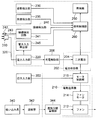
- FIG. 3 is a block diagram showing an electrical system of the vacuum cleaner 100 of FIGS. 1 and 2.
- FIG. 3 also shows an outline of the dust and air flow.
- the vacuum cleaner main body 200 includes a battery housing unit 202, a charge control unit 206, an electric blower 210, a motor control unit 216, a power input unit 220, a posture detection unit 230, an illuminance detection unit 235, and connection detection.
- a circuit 241, a power input detection unit 245, an illumination unit 250, an illumination control unit 260, and a dust separation and accumulation unit 344 are included.
- the electric blower 210 includes a fan 212 and a fan motor 214.
- the secondary battery 204 is detachably attached to the battery housing unit 202, and the secondary battery 204 is electrically connected to the charge control unit 206 in the state of being attached to the battery housing unit 202.
- the power input unit 220 supplies the power input from the external power source 420 via the outlet 410, the plug 310, and the power cord 320 to the charging control unit 206.
- the charging control unit 206 charges the secondary battery 204 with the power from the power input unit 220.
- the operation input unit 350 is provided in the handle 330, for example, and is operated when the operator 450 uses the vacuum cleaner 100 for cleaning.
- the motor control unit 216 controls the start, stop, rotation speed, etc. of the fan motor 214 according to the operation input from the operation input unit 350.
- the motor control unit 216 operates with power from the secondary battery 204, and drives the fan motor 214 using power from the secondary battery 204.
- the fan motor 214 When the fan motor 214 is rotated, the fan 212 is rotated, whereby a negative pressure is formed inside the suction tool 340 and the connecting pipe 342, and dust-containing air is absorbed by the suction tool 340 as indicated by a dotted line in FIG. 3.
- the dust is sucked and sent to the dust separation and accumulation unit 344 via the connecting pipe 342, and the dust is accumulated in the dust separation and accumulation unit 344.
- the air that has passed through the dust separation and accumulation unit 344 is discharged to the outside of the cleaner body 200.
- the vacuum cleaner 100 When the vacuum cleaner 100 is not used for cleaning, it is desirable to store the vacuum cleaner body 200 in an upright state. This is to reduce the floor area required for storage. In addition, it is desirable to charge the secondary battery 204 during storage.
- the vacuum cleaner 100 is supported by the storage mechanism 400 in an upright posture with respect to the floor surface and stored in this state. Then, the plug 310 is inserted into the outlet 410.
- the power from the external power source 420 is supplied to the cleaner body 200 via the plug 310 and the power cord 320, and the secondary battery is supplied via the power input unit 220 and the charging control unit 206. Electric power is supplied to 204 and the secondary battery 204 is charged.
- the charging control is performed by the charging control unit 206.
- the electric vacuum cleaner 100 When cleaning, the electric vacuum cleaner 100 is generally used with the plug 310 pulled out from the outlet 410. However, the plug 310 may remain inserted into the outlet 410 as long as the plug 310 can be cleaned while being inserted into the outlet 410.
- the motor control unit 216 rotates the fan motor 214 with the electric power from the secondary battery 204 in accordance with the operation input from the operation input unit 350, and the fan 212 driven by the fan motor 214 causes the floor to rotate. Dust on the surface and the like is sent from the suction tool 340 to the dust separation and accumulation unit 344 via the connecting pipe 342.
- the vacuum cleaner 100 is supported by the storage mechanism 400 in an upright state during storage.
- storage mechanism 400 is a mechanism for standing up electric vacuum cleaner 100, and is a stand for leaning up electric vacuum cleaner 100.
- the vacuum cleaner 100 has an elongated shape as a whole, and “upright” means that the handle 330 of the vacuum cleaner 100 is above the suction tool 340 and the elongated vacuum cleaner.
- the direction close to the vertical direction refers to a direction in which the difference from the vertical direction is within 30 degrees, for example.
- the storage mechanism 400 is a structure that supports the vacuum cleaner 100, and the suction tool 340 is brought into contact with the floor surface with the connecting pipe 342 and the suction tool 340 attached to the cleaner body 200.
- the cleaner main body 200 is inclined obliquely, and the side surface (surface of the side wall portion) 208 of the housing 207 is in contact with and supported by the support surface 402 of the storage mechanism 400.
- the posture detection unit 230 detects the posture of the vacuum cleaner 100 and outputs the detection result to the illumination control unit 260.
- the posture detection unit 230 detects the posture of the vacuum cleaner 100 as a whole, for example, by detecting the posture of the vacuum cleaner main body 200.
- the posture detection unit 230 includes, for example, a sensor (such as an acceleration sensor) that detects the posture. As this posture, for example, an inclination with respect to the vertical direction is detected.
- the illuminance detection unit 235 detects the illuminance around the cleaner body 200 and outputs the detection result to the illumination control unit 260.
- the illuminance detection unit 235 includes, for example, a sensor (illuminance sensor) that can measure the illuminance on the surface of the housing 207 of the cleaner body 200.
- the connection detection circuit 241 forms part of the connection detection unit 240.
- the connection detection unit 240 detects the connection of the power input unit 220 to the external power supply 420 (therefore, the connection of the cleaner body 200 to the external power supply 420), and outputs the detection result to the illumination control unit 260. For example, the connection detection unit 240 determines whether or not the plug 310 is connected to the outlet 410.
- the connection detection unit 240 includes, for example, a contact sensor in addition to the connection detection circuit 241.
- FIG. 1 An example of this contact sensor is shown in FIG.
- a contact 242 is provided on a part of the plug 310.
- the contact 242 contacts the surface of the outlet 410 when the plug 310 is inserted into the outlet 410 to detect the insertion.
- a signal indicating the detection result is transmitted to the connection detection circuit 241 via the signal line 243, and is transmitted from the connection detection circuit 241 to the illumination control unit 260.
- the power input detection unit 245 detects the supply of power from the external power supply 420 to the power input unit 220 (therefore, the supply of power from the external power supply 420 to the cleaner body 200), and outputs the detection result to the illumination control unit 260. To do.
- the power input detection unit 245 includes, for example, a sensor that can detect whether or not power is input by detecting a current flowing from the power cord 320 to the power input unit 220. This sensor is composed of, for example, a current sensor.
- the attitude detection unit 230, the illuminance detection unit 235, the connection detection unit 240, and the power input detection unit 245 operate with power from the secondary battery 204.
- the illumination control unit 260 controls lighting and extinguishing of the illumination unit 250 according to detection results by the attitude detection unit 230, the illuminance detection unit 235, the connection detection unit 240, and the power input detection unit 245.
- the illumination control unit 260 turns on the illumination unit 250 with the electric power from the secondary battery 204.
- the illumination unit 250 is provided so as to illuminate upward when the vacuum cleaner 100 is lit in an upright state.
- the illumination unit 250 is provided so as to be positioned on the upper side of the vacuum cleaner 100, for example, the upper side of the vacuum cleaner main body 200 in a state where the vacuum cleaner 100 is standing upright, and the ceiling in the upward direction is wide in that state. Desirably configured to illuminate over a range. This is because such a configuration is advantageous for grasping the surrounding situation when a power failure occurs.
- the illumination unit 250 When the vacuum cleaner 100 is in use, the illumination unit 250 is maintained in the off state. When the vacuum cleaner 100 is not in use, the operation in the power failure monitoring mode is started. In this power failure monitoring mode, the illumination control unit 260 detects the occurrence of a power failure and controls the lighting unit 250 to be turned on and off. Whether or not the vacuum cleaner 100 is in a non-use state is determined based on an operation by the operation input unit 350, for example. For example, when a predetermined time has elapsed after the fan 212 is turned off by the operation input unit 350, it is determined that the non-use state has started, and when the fan 212 is turned on by the operation input unit 350, the non-use state is immediately set. Judge that it is over.
- the illumination control unit 260 monitors the outputs (indicating detection results) of the attitude detection unit 230, the illuminance detection unit 235, the connection detection unit 240, and the power input detection unit 245, and based on these outputs.
- the lighting unit 250 is turned on and off. Processing for this control will be described with reference to FIG.
- step ST ⁇ b> 11 it is determined whether or not the cleaner body 200 is connected to the external power supply 420 based on the output of the connection detection unit 240. If “connected” (YES in step ST11), the process proceeds to step ST12.
- step ST12 based on the output of the power input detection unit 245, it is determined whether or not power is being supplied from the external power source 420 to the cleaner body 200. When it is determined that “not supplied” (NO in step ST12), the process proceeds to step ST13.
- step ST13 based on the output of the illuminance detection unit 235, it is determined whether or not the illuminance around the cleaner body 200 is greater than or equal to a threshold value. If not above the threshold (NO in step ST13), the process proceeds to step ST14.
- step ST14 based on the output of the posture detection unit 230, it is determined whether or not the vacuum cleaner 100 is in an upright state. If it is an upright state (YES in step ST14), the process proceeds to step ST15.
- step ST15 the illumination unit 250 is turned on. That is, if it has been lit before that, the lighting state is maintained. If it has been extinguished before that, it is changed to a lighting state.
- step ST16 the illumination unit 250 is turned off. That is, if the light has been turned off before that, the light-off state is maintained. If it was lit before that, it is switched to the extinguished state.
- the illumination control unit 260 performs the following control. That is, the illumination control unit 260 turns on the illumination unit 250 when all of the following four conditions (a) to (d) are satisfied.
- C From the detection result by the illuminance detection unit 235, it is determined that the illuminance around the cleaner body 200 is less than the threshold value.
- D From the detection result by the posture detection unit 230, it is determined that the vacuum cleaner 100 is in an upright state.
- the illumination unit 250 is turned off.
- the above conditions (a) and (b) are satisfied when a power failure occurs, and only in such a case, the illumination control unit 260 turns on the illumination unit 250. Even if the above condition (b) is satisfied, if the above condition (a) is not satisfied, the illumination unit 250 is not turned on. This is because there is a possibility that power is not supplied from the external power source 420 because the plug 310 is not inserted into the outlet 410 because of a power failure.
- the lighting control unit 260 does not light the lighting unit 250 when the above condition (c) is not satisfied. This is because the ambient light is in a bright state (a state where sunlight is received or another light is lit). In this case, even if a power failure occurs, the surroundings are bright. This is because it is not necessary to turn on the illumination unit 250.
- the illumination control unit 260 does not turn on the illumination unit 250. This is to prevent the illumination light of the illumination unit 250 from directly entering the human eye even during a power failure.
- the illumination unit 250 is turned on when all of the above conditions (a), (b), (c), and (d) are satisfied. (B) If the conditions (a) and (b) are satisfied, the illumination unit 250 may be turned on (even if the condition (c) or (d) is not satisfied) (B) If the conditions (a), (b), and (c) are satisfied, the illumination unit 250 may be turned on (even if the condition (d) is not satisfied) (C) If the conditions (a), (b), and (d) are satisfied, the illumination unit 250 may be turned on (even if the condition (c) is not satisfied).
- the power input detection unit 245 is a sensor that can detect a current flowing from the power cord 320 to the power input unit 220, and is configured by, for example, a current sensor. It operates with power from the battery 204.
- the present invention is not limited to such a configuration. For example, when a current from the external power supply 420 flows, a signal indicating that there is power input is output by the current, and if not, the above signal may not be output.
- the storage mechanism 400 is provided as an accessory of the vacuum cleaner 100.
- an existing structure that can act as a support for example, a room for storing a vacuum cleaner is provided.
- a wall may be used as the storage mechanism 400.
- the vacuum cleaner 100 may be configured to be independent.
- Modification 4 The first embodiment has been described on the assumption that the electric vacuum cleaner is of a stick type. However, the present invention can also be applied when the electric vacuum cleaner is of a handy type. It is also applicable to the case where is a canister type. The present invention is also applicable to a vacuum cleaner (robot type vacuum cleaner) that performs autonomous cleaning.
- a vacuum cleaner robot type vacuum cleaner
- the illumination unit 250 is provided so as to illuminate the upper direction when the vacuum cleaner 100 is standing upright.
- the vacuum cleaner 100 is elongated as shown in FIG. 1 and the upper end of the vacuum cleaner 100 in the storage state, that is, the position where the illumination unit 250 is provided is above the average human eye, the illumination unit 250 illuminates upward. Is provided, there is an advantage that the illumination light from the illumination unit 250 does not directly enter the human eye.
- this point is not essential, and it may be provided so as to illuminate a predetermined direction other than the upward direction.
- the illumination unit 250 when the position where the illumination unit 250 is provided is lower than the human eye, the illumination unit 250 is provided so as to illuminate the lower direction, so that the illumination light can be prevented from directly entering the human eye.
- Modification 7 The present invention is also applicable when the cleaner body 200 is separable from one or more of the suction tool 340, the connecting tube 342, and the handle 330.
- the posture detection unit 230 detects the posture of the cleaner main body 200, and the illumination control unit 260 is in a state where the cleaner main body 200 faces a predetermined direction from the detection result by the posture detection unit 230. It will be judged whether or not.
- the vacuum cleaner main body 200 may be configured to be able to maintain a predetermined posture even if not supported by the storage mechanism 400, that is, to be able to stand on its own.
- FIG. 1 the storage mechanism 400 has only a function of supporting the vacuum cleaner 100. However, as shown in FIG. 6, the storage mechanism 400 may serve as a charging stand or a charging stand. good.
- the power supply terminals 404 and 405 of the storage mechanism 400 and the power receiving terminals 224 and 225 of the cleaner body 200 are electrically connected in a state where the vacuum cleaner body 200 is supported by the storage mechanism 400.
- the storage mechanism 400 has a power cord 320 and a plug 310, and the plug 310 is inserted into the outlet 410.
- connection detection unit 240 a unit that detects the connection between the outlet 410 and the plug 310 and detects the connection between the power feeding terminals 404 and 405 and the power receiving terminals 224 and 225 is used. When the connection is detected in both of them, it is determined that the cleaner body 200 is connected to the external power source.
- FIG. 7 shows a contact sensor that can be used to detect the connection between the power supply terminals 404 and 405 and the power reception terminals 224 and 225.
- the contact 221 is provided adjacent to the power receiving terminals 224 and 225 so as to protrude from the side surface (surface of the side wall portion) 208 of the housing 207 of the cleaner body 200. .
- the contact 221 contacts the support surface 402 of the storage mechanism 400 when the power receiving terminals 224 and 225 are pressed against the power feeding terminals 404 and 405, so that the electrical connection between the power receiving terminals 224 and 225 and the power feeding terminals 404 and 405 is achieved.
- a dynamic connection is detected.
- a signal indicating the detection result is transmitted to the connection detection circuit 241 via the signal line 223.
- the connection detection circuit 241 determines that the plug 310 is connected to the outlet 410 from the detection result transmitted through the signal line 243 and the detection result transmitted through the signal line 223 (a1), and receives power. When it is determined that the terminals 224 and 225 are connected to the power supply terminals 404 and 405 (a2), it is determined that the cleaner body 200 is connected to the external power source 420.
- connection detection circuit 241 (A1) The condition that the plug 310 is determined to be connected to the outlet 410 from the output of the contact sensor similar to FIG. (A2) When the condition that the power receiving terminals 224 and 225 are determined to be connected to the power feeding terminals 404 and 405 is satisfied from the output of the contact sensor in FIG. 7, the above condition (a) is satisfied. Judge that The connection detection circuit 241 determines that the condition (a) is not satisfied when at least one of the conditions (a1) and (a2) is not satisfied.
- connection detection circuit 241 The determination result by the connection detection circuit 241 is transmitted to the illumination control unit 260 as the detection result of the connection detection unit 240.
- the modification applicable to the first embodiment can also be applied to the second embodiment.
- the lighting unit when a power failure occurs, the lighting unit is automatically turned on, so that the situation can be quickly grasped. Moreover, since the illumination part is provided in the vacuum cleaner, a separate outlet and a separate secondary battery are unnecessary.
- vacuum cleaners are used relatively frequently for cleaning, and are often connected to a power source for charging by the user, thus activating special awareness in the event of a power outage. It is possible to ensure emergency lighting.
- the illumination unit 250 is turned on when the above condition (c) is satisfied, the lighting can be omitted when the periphery of the cleaner body 200 is bright, and wasteful power consumption is achieved. Can be avoided.
- the illumination unit 250 is turned on when the above condition (d), or more generally, the above condition (d ′) is satisfied, the illumination light from the illumination unit 250 is human. Can be prevented from entering the eyes directly.
- the illumination control unit 260 the posture detection unit 230, the illuminance detection unit 235, the connection detection unit 240, and the power input detection unit 245 can be realized by a processing circuit.
- the processing circuit may be dedicated hardware or a CPU that executes a program stored in a memory.
- the functions of the illumination control unit 260, the attitude detection unit 230, the illuminance detection unit 235, the connection detection unit 240, and the power input detection unit 245 are realized by software, firmware, or a combination of software and firmware. Is done.
- Software or firmware is described as a program and stored in a memory. The processing circuit reads out and executes the program stored in the memory, thereby realizing the functions of the illumination control unit 260, the attitude detection unit 230, the illuminance detection unit 235, the connection detection unit 240, and the power input detection unit 245.
- the illumination control unit 260 when executed by the processing circuit, their functions are executed as a result.
- the illumination control unit 260 the attitude detection unit 230, the illuminance detection unit 235, the connection detection unit 240, and the power input detection unit 245 are realized by dedicated hardware, and part of them are software or firmware It may be realized.
- the processing circuit can realize the functions described above by hardware, software, firmware, or a combination thereof.
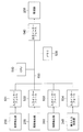
- FIG. 8 shows an example of a configuration when the function of the illumination control unit 260 is realized by a computer (indicated by reference numeral 50) including a single CPU that constitutes the processing circuit.
- a computer 500 shown in FIG. 8 includes a CPU 510, a memory 520, input interfaces 531 to 534, and an output interface 540, which are connected by a bus 550. Signals (detection results) from the attitude detection unit 230, the illuminance detection unit 235, the connection detection unit 240, and the power input detection unit 245 in FIG. 3 are input to the input interfaces 531 to 534, respectively.
- the CPU 510 operates in accordance with a program stored in the memory 520, performs the above-described illumination control unit 260 on the signals (detection results) input via the input interfaces 531 to 534, and displays the determination results. Based on this, control for turning on or off the illumination unit 250 is performed. That is, a control signal generated based on the determination result is supplied to the illumination unit 250 via the output interface 540, and the illumination unit 250 is turned on or off.
- the content of processing by the CPU 510 is the same as that described with reference to FIG. Data generated in the course of processing is held in the memory 520.
- the same effect as described for the illumination control unit 260 can be obtained for a program that causes a computer to execute processing in the illumination control method performed by the illumination control unit 260.
- attitude detection unit 230 the illuminance detection unit 235, the connection detection unit 240, and the power input detection unit 245 are realized by a processing circuit.
Abstract
Description
なお、停電が発生したときに自動的に点灯する照明器具も知られているが、そのような照明器具には、専用のコンセントが必要であり、また停電発生時の点灯のための別個の二次電池が必要であるという問題がある。 However, the above-described conventional vacuum cleaner is turned on after an operation by the operator, and is not automatically turned on when a power failure occurs.
Note that lighting fixtures that automatically turn on when a power failure occurs are also known, but such lighting fixtures require a dedicated outlet, and separate lighting for lighting when a power failure occurs. There is a problem that a secondary battery is necessary.
二次電池を収容する二次電池収容部と、
外部電源からの電力で前記二次電池を充電する充電制御部と、
前記二次電池の電力で駆動される電動送風機と
を備えた掃除機本体を有し、
前記掃除機本体の周囲を照明する照明部と、
前記外部電源の停電を検出したときに、前記二次電池の電力で、前記照明部を点灯させる照明制御部と
をさらに有する。 The vacuum cleaner of the present invention
A secondary battery housing part for housing the secondary battery;
A charge control unit that charges the secondary battery with power from an external power source;
A vacuum cleaner body comprising an electric blower driven by the power of the secondary battery,
An illumination unit that illuminates the periphery of the vacuum cleaner body;
And a lighting control unit that turns on the lighting unit with the power of the secondary battery when a power failure of the external power source is detected.
さらに、電気掃除機は掃除のために比較的頻繁に使用されるものであるので、ユーザが充電のために電源に接続しておくことが多く、従って、停電に備えての特別の意識を働かせることなく、非常用の照明を確保することが可能である。 According to the present invention, when a power failure occurs, the illumination unit is automatically turned on, so that the situation can be quickly grasped. Moreover, since the illumination part is provided in the vacuum cleaner, a separate outlet and a separate secondary battery are unnecessary.
In addition, since vacuum cleaners are used relatively frequently for cleaning, users often connect to a power source for charging, thus activating special awareness in the event of a power outage Therefore, it is possible to ensure emergency lighting.
図1及び図2は、本発明の実施の形態1の電気掃除機100の外観を示す。
図1及び図2に示されるように、電気掃除機100は、掃除機本体200と、プラグ310と、電源コード320と、持ち手330と、吸い込み具340と、連結管342と、操作入力部350とを有する。
1 and 2 show the appearance of the
As shown in FIGS. 1 and 2, the
電動送風機210は、ファン212とファンモータ214とを有する。 As shown in FIG. 3, the vacuum cleaner
The electric blower 210 includes a
充電制御部206は、電力入力部220からの電力により、二次電池204を充電する。 The
The
接続検出部240は接続検出回路241に加えて、例えば接触センサを備えている。 The
The
電気掃除機100が非使用状態にあるときには、停電監視モードでの動作が開始する。この停電監視モードでは、照明制御部260が、停電発生の検出、及び照明部250の点灯及び消灯の制御を行う。
電気掃除機100が非使用状態にあるか否かは、例えば、操作入力部350による操作に基づいて判断する。例えば、操作入力部350でファン212がオフとされてから予め定められた時間が経過したら非使用状態が始まったと判断し、操作入力部350でファン212がオンとされたら、直ちに非使用状態が終わったと判断する。 When the
When the
Whether or not the
最初にステップST11では、接続検出部240の出力に基づいて、掃除機本体200が外部電源420に接続されているか否かを判断する。
「接続されている」場合には(ステップST11でYES)、ステップST12に進む。 The process in FIG. 5 is started at a predetermined time interval, for example.
First, in step ST <b> 11, it is determined whether or not the
If “connected” (YES in step ST11), the process proceeds to step ST12.
「供給されていない」と判断したときは(ステップST12でNO)、ステップST13に進む。 In step ST12, based on the output of the power
When it is determined that “not supplied” (NO in step ST12), the process proceeds to step ST13.
閾値以上でなければ(ステップST13でNO)、ステップST14に進む。 In step ST13, based on the output of the
If not above the threshold (NO in step ST13), the process proceeds to step ST14.
直立状態であれば(ステップST14でYES)、ステップST15に進む。 In step ST14, based on the output of the
If it is an upright state (YES in step ST14), the process proceeds to step ST15.
ステップST16では、照明部250を消灯させる。即ち、それ以前から消灯していたのであれば、消灯状態を維持する。それ以前に点灯していたのであれば、消灯状態に遷移させる。 NO in step ST11 (not connected to a power source), YES in step ST12 (power is supplied), YES in step ST13 (illuminance is greater than or equal to threshold), or NO in step ST14 (not in an upright state) The process proceeds to step ST16.
In step ST16, the
即ち、照明制御部260は、以下4つ条件(a)~(d)の全てが満たされたとき、照明部250を点灯させる。
(a) 接続検出部240による検出結果から、掃除機本体200が外部電源420に接続されていると判断される。
(b) 電力入力検出部245による検出結果から、外部電源420から掃除機本体200に電力が供給されていないと判断される。
(c) 照度検出部235による検出結果から、掃除機本体200の周囲の照度が閾値未満であると判断される。
(d) 姿勢検出部230による検出結果から、電気掃除機100が直立状態にあると判断される。 As a result of performing the processing shown in FIG. 5, the
That is, the
(A) From the detection result by the
(B) From the detection result by the power
(C) From the detection result by the
(D) From the detection result by the
上記の条件(b)が満たされていても、上記の条件(a)が満たされていないときは、照明部250を点灯させない。これは、停電ではなく、プラグ310がコンセント410に差し込まれていないために外部電源420からの電力供給が行われていない可能性があるためである。 The above conditions (a) and (b) are satisfied when a power failure occurs, and only in such a case, the
Even if the above condition (b) is satisfied, if the above condition (a) is not satisfied, the
上記の実施の形態では、上記の条件(a)、(b)、(c)及び(d)のすべてが満たされているときに、照明部250を点灯させることとしているが、代わりに、
(イ) 条件(a)及び(b)が満たされていれば、(条件(c)又は(d)が満たされていなくても、)照明部250を点灯させることとしても良く、
(ロ) 条件(a)、(b)及び(c)が満たされていれば、(条件(d)が満たされていなくても、)照明部250を点灯させることとしても良く、
(ハ) 条件(a)、(b)及び(d)が満たされていれば、(条件(c)が満たされていなくても、)照明部250を点灯させることとしても良い。
In the above embodiment, the
(B) If the conditions (a) and (b) are satisfied, the
(B) If the conditions (a), (b), and (c) are satisfied, the
(C) If the conditions (a), (b), and (d) are satisfied, the
上記の実施の形態では、電力入力検出部245は、電源コード320から電力入力部220に流れ込む電流を検知することができるセンサであり、例えば電流センサで構成されており、このセンサが、二次電池204からの電力によって動作する。
しかしながら、本発明は、このような構成に限定されない。
例えば、外部電源420からの電流が流れたときに、その電流によって、電力の入力があることを示す信号が出力され、そうでないときは上記の信号が出力されない構成であっても良い。 Modification 2
In the above embodiment, the power
However, the present invention is not limited to such a configuration.
For example, when a current from the
上記の実施の形態1では、保管機構400が、電気掃除機100の付属品として提供されるものであるが、支持体として作用しうる既存の構造物、例えば、電気掃除機を保管する部屋の壁を保管機構400として利用しても良い。 Modification 3
In the first embodiment, the
実施の形態1では、電気掃除機がスティック型のものである場合を想定して説明したが、本発明は、電気掃除機がハンディ型のものである場合にも適用可能であり、電気掃除機がキャニスター型のものである場合にも適用可能である。本発明はさらに、自律的に掃除を行う電気掃除機(ロボット型電気掃除機)にも適用可能である。 Modification 4
The first embodiment has been described on the assumption that the electric vacuum cleaner is of a stick type. However, the present invention can also be applied when the electric vacuum cleaner is of a handy type. It is also applicable to the case where is a canister type. The present invention is also applicable to a vacuum cleaner (robot type vacuum cleaner) that performs autonomous cleaning.
実施の形態1に関し、照明部250は、電気掃除機100が直立しているときに、上方向を照らすように設けられている旨説明した。
電気掃除機100が図1に示すように細長く、その保管状態でその上端、即ち照明部250を設ける位置が平均的な人の眼よりも上にある場合、上方向を照らすように照明部250が設けられていれば、照明部250からの照明光が人の眼に直接入射することがないという利点がある。 Modification 5
Regarding the first embodiment, it has been described that the
When the
実施の形態1に関し、直立とは、細長い電気掃除機100の長手方向が鉛直方向に近い方向にある状態をいう旨説明したが、本発明は、電気掃除機100が細長いものである場合に限定されない。要するに、保管時に、電気掃除機100が、予め定められた姿勢の状態、即ち予め定められた方向を向いた状態に置かれる構成であれば良い。
そして、その状態で、照明部250が予め定められた方向、例えば上方向を照らすように構成されていれば良い。
その場合、上記の条件(d)の代わりに、条件(d)を一般化した下記の条件(d’)を用いる。
(d’) 姿勢検出部230による検出結果から、電気掃除機100が予め定められた方向を向いた状態にあると判断される。 Modification 6
In the first embodiment, upright has been described to mean a state in which the longitudinal direction of the
In this state, the
In that case, the following condition (d ′) obtained by generalizing the condition (d) is used instead of the condition (d).
(D ′) From the detection result by the
本発明はまた、掃除機本体200が、吸い込み具340、連結管342及び持ち手330の一つ以上から分離可能である場合にも適用可能である。その場合、姿勢検出部230は、掃除機本体200の姿勢を検出し、照明制御部260は、姿勢検出部230による検出結果から、掃除機本体200が予め定められた方向を向いた状態にあるか否かの判断をすることになる。 Modification 7
The present invention is also applicable when the
上記の実施の形態1では、保管機構400は、電気掃除機100を支持する機能のみを有するが、保管機構400が、図6に示すように、充電台或いは充電スタンドを兼ねるものであっても良い。 Embodiment 2. FIG.
In the first embodiment, the
そして、それらの双方において接続が検知された場合に、掃除機本体200が外部電源に接続されているとの判断がなされる。 Further, as the
When the connection is detected in both of them, it is determined that the
図7の例では、受電端子224、225に隣接して、掃除機本体200の筐体207の側面(筐体の側壁部分の表面)208から突出するように、接触子221が設けられている。この接触子221は、受電端子224、225が給電端子404、405に押し付けられたとき、保管機構400の支持面402に当接することで、受電端子224、225と給電端子404、405との電気的接続を検知する。検知結果を示す信号は、信号線223を介して接続検出回路241に伝えられる。 FIG. 7 shows a contact sensor that can be used to detect the connection between the
In the example of FIG. 7, the
(a1) 図4と同様の接触センサの出力から、プラグ310がコンセント410に接続されていると判断されるという条件と、
(a2) 図7の接触センサの出力から、受電端子224、225が給電端子404、405に接続されていると判断されるという条件
とがともに満たされるとき、上記の条件(a)が満たされていると判断する。
接続検出回路241は、上記の条件(a1)及び(a2)の少なくとも一つが満たされない場合には、上記の条件(a)が満たされていないと判断する。 That is, the
(A1) The condition that the
(A2) When the condition that the
The
このように、処理回路は、ハードウェア、ソフトウェア、ファームウェア、またはこれらの組み合わせによって、上述の各機能を実現することができる。 In addition, some of the functions of the
As described above, the processing circuit can realize the functions described above by hardware, software, firmware, or a combination thereof.
図8に示されるコンピュータ500は、CPU510と、メモリ520と、入力インターフェース531~534と、出力インターフェース540とを備え、これらはバス550で接続されている。
入力インターフェース531~534には、それぞれ図3の姿勢検出部230、照度検出部235、接続検出部240、及び電力入力検出部245からの信号(検出結果)が入力される。 FIG. 8 shows an example of a configuration when the function of the
A computer 500 shown in FIG. 8 includes a
Signals (detection results) from the
Claims (10)
- 二次電池を収容する二次電池収容部と、
外部電源からの電力で前記二次電池を充電する充電制御部と、
前記二次電池の電力で駆動される電動送風機と
を備えた掃除機本体を有し、
前記掃除機本体の周囲を照明する照明部と、
前記外部電源の停電を検出したときに、前記二次電池の電力で、前記照明部を点灯させる照明制御部と
をさらに有する電気掃除機。 A secondary battery housing part for housing the secondary battery;
A charge control unit that charges the secondary battery with power from an external power source;
A vacuum cleaner body comprising an electric blower driven by the power of the secondary battery,
An illumination unit that illuminates the periphery of the vacuum cleaner body;
An electric vacuum cleaner further comprising: an illumination control unit that turns on the illumination unit with the power of the secondary battery when a power failure of the external power source is detected. - 前記掃除機本体の前記外部電源への接続を検出する接続検出部と、
前記外部電源から前記掃除機本体への電力の供給を検出する電力入力検出部とをさらに有し、
前記照明制御部は、前記接続検出部による検出結果及び前記電力入力検出部による検出結果に基づいて前記外部電源の停電を検出する
ことを特徴とする請求項1に記載の電気掃除機。 A connection detector for detecting connection of the vacuum cleaner body to the external power source;
A power input detection unit that detects supply of power from the external power source to the cleaner body;
The vacuum cleaner according to claim 1, wherein the illumination control unit detects a power failure of the external power source based on a detection result by the connection detection unit and a detection result by the power input detection unit. - 前記照明制御部は、前記接続検出部による前記検出結果及び前記電力入力検出部による検出結果を監視し、
前記接続検出部による検出結果から、前記掃除機本体が前記外部電源に接続されていると判断されるという条件(a)、及び
前記電力入力検出部による検出結果から、前記外部電源から前記掃除機本体へ電力が供給されていないと判断されるという条件(b)
がともに満たされたとき、前記照明制御部は、前記照明部を点灯させる
ことを特徴とする請求項2に記載の電気掃除機。 The illumination control unit monitors the detection result by the connection detection unit and the detection result by the power input detection unit,
From the detection result by the connection detection unit, the condition (a) that it is determined that the cleaner body is connected to the external power source, and from the detection result by the power input detection unit, the vacuum cleaner from the external power source. Condition (b) that it is determined that power is not supplied to the main body
When both are satisfy | filled, the said illumination control part makes the said illumination part light. The vacuum cleaner of Claim 2 characterized by the above-mentioned. - 前記照明制御部は、上記の条件(a)及び(b)の少なくとも一つが満たされないときに、前記照明部を消灯させる
ことを特徴とする請求項3に記載の電気掃除機。 The vacuum cleaner according to claim 3, wherein the lighting control unit turns off the lighting unit when at least one of the conditions (a) and (b) is not satisfied. - 前記掃除機本体の周囲の照度を検出する照度検出部をさらに有し、
前記照明制御部は、前記照度検出部による検出結果を監視し、上記の条件(a)及び(b)に加え、さらに、
前記照度検出部による検出結果から、前記掃除機本体の周囲の照度が閾値未満であると判断されるという条件(c)
が満たされたときに、前記照明部を点灯させる
ことを特徴とする請求項3に記載の電気掃除機。 It further has an illuminance detector that detects the illuminance around the vacuum cleaner body,
The illumination control unit monitors the detection result by the illuminance detection unit, and in addition to the above conditions (a) and (b),
Condition (c) that it is determined from the detection result by the illuminance detection unit that the illuminance around the cleaner body is less than a threshold value.
The vacuum cleaner according to claim 3, wherein the lighting unit is turned on when is satisfied. - 前記照明制御部は、上記の条件(a)、(b)及び(c)の少なくとも一つが満たされないときに、前記照明部を消灯させる
ことを特徴とする請求項5に記載の電気掃除機。 The vacuum cleaner according to claim 5, wherein the lighting control unit turns off the lighting unit when at least one of the above conditions (a), (b), and (c) is not satisfied. - 前記電気掃除機の姿勢を検出する姿勢検出部をさらに有し、
前記照明制御部は、前記姿勢検出部による検出結果を監視し、上記の条件(a)及び(b)に加え、さらに、
前記姿勢検出部による検出結果から、前記電気掃除機が予め定められた方向を向いた状態にあると判断されるという条件(d’)
が満たされたときに、前記照明部を点灯させる
ことを特徴とする請求項3に記載の電気掃除機。 It further has an attitude detection unit that detects the attitude of the vacuum cleaner,
The illumination control unit monitors the detection result by the posture detection unit, and in addition to the above conditions (a) and (b),
Condition (d ′) that it is determined from the detection result by the posture detection unit that the vacuum cleaner is in a predetermined direction.
The vacuum cleaner according to claim 3, wherein the lighting unit is turned on when is satisfied. - 前記照明制御部は、上記の条件(a)、(b)及び(d’)の少なくとも一つが満たされないときに前記照明部を消灯させる
ことを特徴とする請求項7に記載の電気掃除機。 The vacuum cleaner according to claim 7, wherein the lighting control unit turns off the lighting unit when at least one of the above conditions (a), (b), and (d ') is not satisfied. - 前記電気掃除機が細長い形状のものであり、前記予め定められた方向を向いた状態が直立状態である
ことを特徴とする請求項7又は8に記載の電気掃除機。 The vacuum cleaner according to claim 7 or 8, wherein the vacuum cleaner has an elongated shape, and the state facing the predetermined direction is an upright state. - 前記照明部は、前記電気掃除機が直立状態にあるときに、上方向を照明するように設けられていることを特徴とする請求項9に記載の電気掃除機。 10. The vacuum cleaner according to claim 9, wherein the illumination unit is provided to illuminate upward when the vacuum cleaner is in an upright state.
Priority Applications (6)
| Application Number | Priority Date | Filing Date | Title |
|---|---|---|---|
| JP2017548542A JPWO2017077577A1 (en) | 2015-11-02 | 2015-11-02 | Electric vacuum cleaner |
| CN201580084200.2A CN108348122A (en) | 2015-11-02 | 2015-11-02 | Electric dust collector |
| AU2015413796A AU2015413796B2 (en) | 2015-11-02 | 2015-11-02 | Electric Vacuum cleaner |
| PCT/JP2015/080949 WO2017077577A1 (en) | 2015-11-02 | 2015-11-02 | Vacuum cleaner |
| EP15907763.5A EP3372138B1 (en) | 2015-11-02 | 2015-11-02 | Vacuum cleaner |
| TW104142220A TWI618524B (en) | 2015-11-02 | 2015-12-16 | Electric vacuum cleaner |
Applications Claiming Priority (1)
| Application Number | Priority Date | Filing Date | Title |
|---|---|---|---|
| PCT/JP2015/080949 WO2017077577A1 (en) | 2015-11-02 | 2015-11-02 | Vacuum cleaner |
Publications (1)
| Publication Number | Publication Date |
|---|---|
| WO2017077577A1 true WO2017077577A1 (en) | 2017-05-11 |
Family
ID=58662384
Family Applications (1)
| Application Number | Title | Priority Date | Filing Date |
|---|---|---|---|
| PCT/JP2015/080949 WO2017077577A1 (en) | 2015-11-02 | 2015-11-02 | Vacuum cleaner |
Country Status (6)
| Country | Link |
|---|---|
| EP (1) | EP3372138B1 (en) |
| JP (1) | JPWO2017077577A1 (en) |
| CN (1) | CN108348122A (en) |
| AU (1) | AU2015413796B2 (en) |
| TW (1) | TWI618524B (en) |
| WO (1) | WO2017077577A1 (en) |
Cited By (1)
| Publication number | Priority date | Publication date | Assignee | Title |
|---|---|---|---|---|
| WO2018235767A1 (en) * | 2017-06-22 | 2018-12-27 | 東芝ライフスタイル株式会社 | Electric vacuum cleaner apparatus |
Families Citing this family (2)
| Publication number | Priority date | Publication date | Assignee | Title |
|---|---|---|---|---|
| JP7120772B2 (en) * | 2018-02-15 | 2022-08-17 | 東芝ライフスタイル株式会社 | vacuum cleaner |
| CN111082497B (en) * | 2020-01-09 | 2021-08-17 | 惠州拓邦电气技术有限公司 | Power failure judgment method for cleaning equipment and cleaning equipment |
Citations (4)
| Publication number | Priority date | Publication date | Assignee | Title |
|---|---|---|---|---|
| JP3014106U (en) * | 1995-01-28 | 1995-08-01 | 株式会社アサヒ産業 | Blackout emergency radio |
| JP2009229000A (en) * | 2008-03-24 | 2009-10-08 | Mitsubishi Electric Corp | Ventilation fan with lighting device |
| JP2013078656A (en) * | 2013-01-22 | 2013-05-02 | Kazuo Hanno | Vacuum cleaner with speaker vibration dirt removing function |
| JP2015154869A (en) * | 2014-02-21 | 2015-08-27 | 日立アプライアンス株式会社 | Suction port body of vacuum cleaner and vacuum cleaner using suction port body |
Family Cites Families (15)
| Publication number | Priority date | Publication date | Assignee | Title |
|---|---|---|---|---|
| JPH07226102A (en) * | 1994-02-10 | 1995-08-22 | Tec Corp | No powder emergency light device |
| JPH11265601A (en) * | 1998-03-18 | 1999-09-28 | Sanyo Electric Co Ltd | Emergency light system with communication function |
| JP3861564B2 (en) * | 2000-05-17 | 2006-12-20 | 株式会社日立製作所 | Vacuum cleaner |
| KR100443414B1 (en) * | 2002-04-23 | 2004-08-11 | 장성완 | A cleaner including safety lamp |
| JP4278637B2 (en) * | 2005-06-07 | 2009-06-17 | 益男 片田 | Refrigerator with foot light |
| JP5256981B2 (en) * | 2008-10-08 | 2013-08-07 | パナソニック株式会社 | Electric vacuum cleaner |
| JP5584460B2 (en) * | 2009-12-22 | 2014-09-03 | パナソニック株式会社 | Power supply apparatus, lighting equipment for disaster prevention and lighting system for disaster prevention using the same |
| JP5679197B2 (en) * | 2011-02-22 | 2015-03-04 | 野口 宏和 | Fluorescent lamp type LED lighting device |
| DE102012105378B4 (en) * | 2012-06-21 | 2015-04-16 | Miele & Cie. Kg | Vacuum cleaner with a lighting device and method for operating a vacuum cleaner with a lighting device |
| CN103841735A (en) * | 2012-11-23 | 2014-06-04 | 新昌县澄潭镇博纳机械厂 | Lamp with emergency power supply |
| CN104207730B (en) * | 2013-05-30 | 2017-03-29 | 赵立国 | Vertical type multifunctional floor cleaning chip syringe |
| TWM472503U (en) * | 2013-07-26 | 2014-02-21 | zheng-qian Zhang | Rechargeable vacuum cleaner |
| CN204559223U (en) * | 2015-02-28 | 2015-08-12 | 智嘉通讯科技(东莞)有限公司 | A kind of multifunctional emergency light |
| CN204518186U (en) * | 2015-04-21 | 2015-07-29 | 陈莉莉 | A kind of emergency lighting circuit for lamp |
| CN104918382A (en) * | 2015-06-17 | 2015-09-16 | 合肥扬帆通信元器件有限公司 | Intelligent switch on/off system of indoor illuminating lamp |
-
2015
- 2015-11-02 CN CN201580084200.2A patent/CN108348122A/en active Pending
- 2015-11-02 EP EP15907763.5A patent/EP3372138B1/en active Active
- 2015-11-02 WO PCT/JP2015/080949 patent/WO2017077577A1/en unknown
- 2015-11-02 AU AU2015413796A patent/AU2015413796B2/en not_active Ceased
- 2015-11-02 JP JP2017548542A patent/JPWO2017077577A1/en active Pending
- 2015-12-16 TW TW104142220A patent/TWI618524B/en not_active IP Right Cessation
Patent Citations (4)
| Publication number | Priority date | Publication date | Assignee | Title |
|---|---|---|---|---|
| JP3014106U (en) * | 1995-01-28 | 1995-08-01 | 株式会社アサヒ産業 | Blackout emergency radio |
| JP2009229000A (en) * | 2008-03-24 | 2009-10-08 | Mitsubishi Electric Corp | Ventilation fan with lighting device |
| JP2013078656A (en) * | 2013-01-22 | 2013-05-02 | Kazuo Hanno | Vacuum cleaner with speaker vibration dirt removing function |
| JP2015154869A (en) * | 2014-02-21 | 2015-08-27 | 日立アプライアンス株式会社 | Suction port body of vacuum cleaner and vacuum cleaner using suction port body |
Cited By (7)
| Publication number | Priority date | Publication date | Assignee | Title |
|---|---|---|---|---|
| WO2018235767A1 (en) * | 2017-06-22 | 2018-12-27 | 東芝ライフスタイル株式会社 | Electric vacuum cleaner apparatus |
| JP2019005070A (en) * | 2017-06-22 | 2019-01-17 | 東芝ライフスタイル株式会社 | Vacuum cleaning device |
| CN110650666A (en) * | 2017-06-22 | 2020-01-03 | 东芝生活电器株式会社 | Electric cleaning device |
| GB2578235A (en) * | 2017-06-22 | 2020-04-22 | Toshiba Lifestyle Products & Services Corp | Electric vacuum cleaner apparatus |
| CN110650666B (en) * | 2017-06-22 | 2021-06-25 | 东芝生活电器株式会社 | Electric cleaning device |
| GB2578235B (en) * | 2017-06-22 | 2022-05-04 | Toshiba Lifestyle Products & Services Corp | Electric vacuum cleaner apparatus |
| US11452424B2 (en) | 2017-06-22 | 2022-09-27 | Toshiba Lifestyle Products & Services Corporation | Electric vacuum cleaner apparatus |
Also Published As
| Publication number | Publication date |
|---|---|
| TWI618524B (en) | 2018-03-21 |
| AU2015413796B2 (en) | 2019-03-21 |
| CN108348122A (en) | 2018-07-31 |
| EP3372138A1 (en) | 2018-09-12 |
| AU2015413796A1 (en) | 2018-03-22 |
| TW201716025A (en) | 2017-05-16 |
| EP3372138B1 (en) | 2019-12-25 |
| JPWO2017077577A1 (en) | 2018-04-26 |
| EP3372138A4 (en) | 2018-11-14 |
Similar Documents
| Publication | Publication Date | Title |
|---|---|---|
| US7352153B2 (en) | Mobile robotic system and battery charging method therefor | |
| KR102009202B1 (en) | Dust collector | |
| WO2017077577A1 (en) | Vacuum cleaner | |
| KR20160023134A (en) | Vacuum cleaner | |
| JP6492282B2 (en) | Electric vacuum cleaner | |
| JP2018094021A (en) | Dust collector | |
| JP6358100B2 (en) | Electric vacuum cleaner | |
| TWI597915B (en) | Vacuum cleaner | |
| JP4920779B2 (en) | Vacuum cleaner | |
| JP2021069484A (en) | Vacuum cleaner | |
| GB2490256A (en) | Mobile electric floor treatment machine | |
| JP2010075472A (en) | Vacuum cleaner | |
| KR20160019358A (en) | Extension tube and electric vacuum cleaner | |
| JP6919601B2 (en) | Vacuum cleaner | |
| US20050231162A1 (en) | Mobile work robot | |
| EP3482667A1 (en) | Dust sensor module and operating method thereof | |
| JP2019088508A (en) | Vacuum cleaner | |
| JP7228463B2 (en) | vacuum cleaner | |
| KR101483399B1 (en) | Light for emergency and lantern | |
| JP2013198703A (en) | Vacuum cleaner | |
| JP4709690B2 (en) | Electric vacuum cleaner | |
| JP2012070872A (en) | Vacuum cleaner | |
| JP2017185094A (en) | Vacuum cleaner | |
| TWM575320U (en) | A vacuum cleaner combined charger and light | |
| JP5214303B2 (en) | Electric vacuum cleaner |
Legal Events
| Date | Code | Title | Description |
|---|---|---|---|
| 121 | Ep: the epo has been informed by wipo that ep was designated in this application |
Ref document number: 15907763 Country of ref document: EP Kind code of ref document: A1 |
|
| ENP | Entry into the national phase |
Ref document number: 2017548542 Country of ref document: JP Kind code of ref document: A |
|
| ENP | Entry into the national phase |
Ref document number: 2015413796 Country of ref document: AU Date of ref document: 20151102 Kind code of ref document: A |
|
| NENP | Non-entry into the national phase |
Ref country code: DE |