WO2017076473A1 - Refrigeration appliance with an additional storage container - Google Patents
Refrigeration appliance with an additional storage container Download PDFInfo
- Publication number
- WO2017076473A1 WO2017076473A1 PCT/EP2015/075957 EP2015075957W WO2017076473A1 WO 2017076473 A1 WO2017076473 A1 WO 2017076473A1 EP 2015075957 W EP2015075957 W EP 2015075957W WO 2017076473 A1 WO2017076473 A1 WO 2017076473A1
- Authority
- WO
- WIPO (PCT)
- Prior art keywords
- storage container
- extensible
- refrigeration appliance
- cover
- refrigeration
- Prior art date
- Legal status (The legal status is an assumption and is not a legal conclusion. Google has not performed a legal analysis and makes no representation as to the accuracy of the status listed.)
- Ceased
Links
Images




Classifications
-
- F—MECHANICAL ENGINEERING; LIGHTING; HEATING; WEAPONS; BLASTING
- F25—REFRIGERATION OR COOLING; COMBINED HEATING AND REFRIGERATION SYSTEMS; HEAT PUMP SYSTEMS; MANUFACTURE OR STORAGE OF ICE; LIQUEFACTION SOLIDIFICATION OF GASES
- F25D—REFRIGERATORS; COLD ROOMS; ICE-BOXES; COOLING OR FREEZING APPARATUS NOT OTHERWISE PROVIDED FOR
- F25D23/00—General constructional features
- F25D23/02—Doors; Covers
- F25D23/04—Doors; Covers with special compartments, e.g. butter conditioners
Definitions
- the present invention relates to a household appliance and more particularly a refrigeration appliance having a storage container in the form of an additional storage unit disposed relative to the inner compartment door of the refrigeration appliance.
- a refrigeration appliance has a plurality of shelves and containers for preserving food items.
- a storage container may typically be arranged in the manner that its base extends in parallel with the base of the appliance so as to be guidably movable out of the internal space of the appliance in order for allowing users to reach stored food items therein.
- another special extractable container can be a container generally designated as a practical food storage container particularly advantageous for its convenience to practically allow easier reach to food items. Therefore, a more efficient and practical storage of certain food items is desirable so as to provide a storage container effecting hygienic preservation of food while at the same time making use of the normally non-used inner side region of the the inner compartment door of the refrigeration appliance. Therefore, a storage container releasably attachable to the inner compartment wall of the refrigeration appliance provides a practical solution for storing food items.
- a prior art publication in the technical field of the present invention may be referred to as CN104374151 among others, the document disclosing a suspension type refrigerator magnetic attraction storage rack and a refrigerator, and belongs to the field of refrigerator manufacturing.
- the suspension type refrigerator magnetic attraction storage rack comprises a plastic slot; a plurality of evenly-arranged magnet slots are formed in the plastic slot and strong magnets are arranged in the magnet slots.
- the magnetic slots coat the peripheries of the strong magnets, and the middles of the strong magnets protrude out of the magnetic slots.
- the strong magnets are square-shaped and beverages, beer, cans and other objects with iron covers can be attracted through the strong magnets and such containers are suspended and hung in the refrigerator.
- the present invention provides a refrigeration appliance having at least one removable and selectively opened storage container releasably attachable to a compartment door or shelf wall portion of the refrigeration appliance as defined by the characterizing features as defined in Claim 1.
- Primary object of the present invention is hence to provide a refrigeration appliance with a selectively opened storage container occupying minimal space when inactive and releasably attachable to the inner compartment door wall in a practically reachable manner.
- the present invention proposes a refrigeration appliance with at least one releasably attachable storage container having a selectively openable structure. It is mounted to a normally non-used portion of a wall adjacent to the base portion of a shelf to create a closed volume storage container.
- the storage container has an extensible covering assembly covering an open space between a storage container housing and a storage container cover in the open position of the storage container cover relative to the storage container housing.
- the storage container is preferably attached to the shelf wall through a first attachment element thereof connectible with a second attachment element of the shelf wall, either magnetically or through mechanical means such as hooking and hanging elements or hook and loop fastening elements.
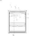
- Fig. 1 demonstrates a general perspective view of an inner compartment door according to the present invention.
- Fig. 2 demonstrates a general front view of an inner compartment door according to the present invention.
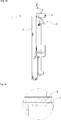
- Fig. 3a demonstrates a lateral cross-sectional view of an inner compartment door along line A-A of Fig 2 according to the present invention.
- Fig. 3b demonstrates an enlarged view of detail A of Fig. 3a according to the present invention.
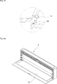
- Fig. 4 demonstrates a perspective view of a storage container for a refrigeration appliance with a first attachment element in unmounted state according to the present invention.
- Fig. 5a demonstrates a storage container housing together with a storage container cover according to the present invention.
- Fig. 5b demonstrates a combined enlarged view of details B of Fig. 5a according to the present invention.
- Fig. 6a demonstrates a front view of the storage container in active storage position with a closed extensible covering assembly according to the present invention.
- Fig. 6b demonstrates a lateral cross-sectional view of the storage container along line B-B of Fig 6a.
- Fig. 6c demonstrates an enlarged view of detail C of Fig. 6b according to the present invention.
- Fig. 6d demonstrates a lateral cross-sectional view of a single extensible unit according to the present invention.
- Fig. 7a demonstrates a perspective view of a laterally cut-out storage container according to the present invention.
- Fig. 7b demonstrates a perspective view of a storage container with a half-opened extensible covering assembly according to the present invention.
- Fig. 7c demonstrates a perspective view of a storage container with a fully closed extensible covering assembly according to the present invention.
- Fig. 7d demonstrates an enlarged view of detail D of Fig. 7a according to the present invention.
- Fig. 8a demonstrates a perspective view of a storage container with a fully opened extensible covering assembly according to the present invention.
- Fig. 8b demonstrates a lateral perspective view of a cut-out storage container of fig. 8a according to the present invention.
- Fig. 8c demonstrates a lateral view of a storage container with a fully opened extensible covering assembly and a closed storage container cover according to the present invention.
- Fig. 8d demonstrates an enlarged view of detail E of Fig. 7a according to the present invention.
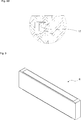
- Fig. 9 demonstrates a perspective view of a fully closed storage container according to the present invention.
- the present invention relates to a household appliance and more particularly a refrigeration appliance (1) having an interior refrigeration cabin, an inner compartment door (2) opening and closing a front side of the refrigeration cabin and at least one side shelf (3) on the inner compartment door (2) for storing food items in a refrigerated manner.
- the refrigeration appliance (1) may typically have a main body with a multitude of storage chambers and the inner compartment door (2) opening and closing the front side of the main body.
- a refrigerating compartment as well as a freezing compartment may be disposed so as to provide separate divisions within the inside of the main body.
- the inner compartment door (2) typically comprises a plurality of shelves (3).
- the inner compartment door (2) of the invention further comprises at least one releasably attachable storage container (6) generally designated as a practically removable storage means for food items such as sandwiches and/or fruits etc. Therefore, the storage container (6) of the invention can be taken out from the inner compartment and as such continues to fulfil food preservation function until it is opened outside the refrigeration appliance (1).
- the storage container (6) is particularly useful in that it allows easy removal and serves as a daily routine storage container, for example in a bag.
- the storage container (6) has a selectively openable structure having a storage container housing (9) and a storage container cover (10) selectively covering the housing.
- the storage container (6) further has an extensible covering assembly (11) consisting of a plurality of extensible units (14).
- Each of the extensible units (14) is structured to have a respective size so that neighboring extensible units (14) having gradually changed dimensions are mountable to each other.
- the extensible covering assembly (11) covers the open space between the storage container housing (9) and the storage container cover (10) when the latter is opened.
- Each extensible unit (14) is formed as a generally U-shaped body rotatably mountable to the storage container housing (9) at both ends of its U-shaped body.
- each successive smaller size extensible unit (14) is mounted to a respective previous extensible unit (14) in a telescopic manner so that all extensible units (14) can be gradually taken to storage position sliding one by one starting from the smallest and lowermost/outermost extensible unit (14) one within another.
- the open position of the storage container cover (10) allows access into the storage container (6). While closure of the storage container cover (10) minimizes the inner volume of the storage container (6) in which case no food item can be stored in this inactive position, closure of the extensible covering assembly (11) while the storage container cover (10) is open, i.e. attaching the extensible units (14) to the opened storage container cover (10) creates a closed storage volume for storing food items. Therefore, the storage container (6) enables practical opening and closing operations by way of lowering or raising the extensible units (14). In other words, the storage container (6) serves as a food preservation box with a collapsible intermediate cover (the extensible covering assembly (11)) in the open position of the storage container cover (10), providing isolation for the food articles stored inside.
- the refrigeration appliance (1) may conventionally have a certain number of storage containers (6), each one connected to the inner compartment door (2) through a first attachment element (7) releasably attachable to a second attachment element (8).
- the second attachment element (8) can be joined to a lateral wall (4) portion parallel to the surface of the inner compartment door (2) or to a shelf wall (5) parallel to the surface of the base portion of the shelf (3). In both cases, the storage container (6) will occupy a normally non-used space region within the refrigeration compartment.
- the storage container housing (9) has cover retention members (12) cooperating with the storage container cover’s (10) engagement members (13) such that the storage container cover (10) is rotatably connected to the storage container housing (9).
- each of any two neighboring extensible units (14) telescopically slidable one within or relative to another preferably has a first directional blocking member (15) blocking further extension of an outer extensible unit (14) and second directional blocking members (16) imparting a closing direction movement (through 16a) to an inner extensible unit (14) and receiving a closing direction movement (through 16b) from an outer extensible unit (14).
- the storage container housing (9) also has a housing connection member (18) for interlocking engagement with the innermost (largest) extensible unit (14).
- the storage container cover (10) can be closed and locked by means of a locking element (17) of the storage container housing (9) as seen in Fig. 9.
- This position advantageously allows for a much smaller space use by the storage container (6) in the refrigeration cabin while still maintained therein.
- the outermost (lowest) extensible unit (14) can be selectively attached to the opened position storage container cover (10) at a raised surface (19) thereof. Therefore, closure of the storage container (6) in the active storage position is ensured.
- the first and second attachment elements (7, 8) effectuate carrying of the storage container (6).
- They can be any suitable means for instance mutually cooperating releasable mechanical connection elements such as hooking and hanging elements (not shown) or alternatively mechanical fastening elements in the form of hook and loop fastening elements (not shown) as those being generally used in diapers and sold under the registered trademark Velcro.
- the releasable connection of the storage container (6) with the first and second attachment elements (7, 8) is preferably effectuated magnetically as delineated below.
- the releasable attachment of the first and second attachment elements (7, 8) is preferably effectuated magnetically in the manner that the first attachment element (7) is made of a material producing a magnetic field (typically a magnetized ferromagnetic material) while the second attachment element (8) is a magnetically responsive material such as a metal strip.
- the second attachment element (8) can alternatively be provided as an integrated part of the lateral wall (4) or the shelf wall (5).
- the first attachment element (7) can be integral with the storage container (6).
- the present invention proposes a refrigeration appliance (1) having an interior refrigeration cabin for storing food items in a refrigerated manner, the interior refrigeration cabin being enclosed by a heat-insulating housing, the refrigeration appliance (1) further having an inner compartment door (2) opening and closing a front side of the refrigeration cabin and having at least one side shelf (3) on the inner compartment door (2) for storing food items .
- At least one releasably attachable storage container (6) having a storage container housing (9) and a storage container cover (10) is attached to the inner compartment door (2).
- the storage container (6) further has a first active storage position in which the storage container cover (10) is in open position relative to the storage container housing (9) and a collapsible intermediate cover as an extensible covering assembly (11) attaching the storage container housing (9) to the storage container cover (10) in the open position of the latter is selectively closable to cover the opened space between the storage container housing (9) and the storage container cover (10) and to create a closed storage volume for storing food items.
- the storage container (6) further has a second passive storage position in which the extensible covering assembly (11) is collapsed to be stored within the storage container housing (9) and the storage container cover (10) is closed.
- the extensible covering assembly (11) comprises a plurality of extensible units (14), each one of which being structured to have a respective gradually changed size.
- each extensible unit (14) is telescopically slidable one by one and one within or relative to another to be gradually taken to active and passive storage positions of the storage container (6).
- each pair of neighboring extensible units (14) have different dimensions and are mountable to each other.
- each extensible unit (14) is formed as a U-shaped body rotatably mountable to the storage container housing (9) at both ends of its U-shaped body.
- the innermost and largest one of the extensible units (14) is directly mountable to the storage container housing (9) and each successive smaller size extensible unit (14) is mountable to a respective previous larger extensible unit (14) in a telescopic manner.
- each of the two neighboring extensible units (14) has a first directional blocking member (15) blocking further extension of an outer extensible unit (14) and second directional blocking members (16) imparting a closing direction movement (16a) to an inner extensible unit (14) and receiving a closing direction movement (16b) from an outer extensible unit (14).
- the storage container housing (9) has a housing connection member (18) for interlocking engagement with the innermost and largest extensible unit (14).
- the storage container cover (10) is locked with the storage container housing (9) by means of a locking element (17).
- the outermost and smallest extensible unit (14) is selectively attachable to the opened position storage container cover (10) at a raised surface (19) thereof.
- the storage container (6) is connected to the inner compartment door (2) through a first attachment element (7) releasably attachable to a second attachment element (8), the second attachment element (8) being joined to a lateral wall (4) portion parallel to the surface of the inner compartment door (2) or to a shelf wall (5) parallel to the surface of the base portion of the shelf (3).
- the storage container housing (9) has cover retention members (12) cooperating with the storage container cover’s (10) engagement members (13) such that the storage container cover (10) is rotatably connected to the storage container housing (9).
- first and second attachment elements (7, 8) are attached to each other magnetically in the manner that the first attachment elements (7) is made of a magnetized material and the second attachment element (8) is a metallic strip.
- first and second attachment elements (7, 8) are attached to each other in the manner that they have mutually cooperating releasable mechanical connection elements in the form of hooking and hanging elements or mechanical fastening elements in the form of hook and loop elements.
- the storage container (6) of the invention is particularly useful in that it allows easy removal and it also fulfils the function of providing a daily routine storage container. Its structure allows an active storage position in the opened position of the storage container cover (10) with the selectively opened extensible covering assembly (11) and an inactive position during which the storage container (6) occupies minimal space in the closed position of the storage container cover (10).
Landscapes
- Engineering & Computer Science (AREA)
- Chemical & Material Sciences (AREA)
- Combustion & Propulsion (AREA)
- Physics & Mathematics (AREA)
- Mechanical Engineering (AREA)
- Thermal Sciences (AREA)
- General Engineering & Computer Science (AREA)
- Devices That Are Associated With Refrigeration Equipment (AREA)
Abstract
The present invention relates to a household appliance and more particularly a refrigeration appliance (1) having a storage container in the form of an additional storage unit disposed relative to the inner compartment door of the refrigeration appliance (1). The present invention more particularly relates to a refrigeration appliance (1) having an interior refrigeration cabin for storing food items in a refrigerated manner, the interior refrigeration cabin being enclosed by a heat-insulating housing, the refrigeration appliance (1) further having an inner compartment door (2) opening and closing a front side of the refrigeration cabin and having at least one side shelf (3) on the inner compartment door (2) for storing food items.
Description
The present invention relates to a household appliance and more particularly a refrigeration appliance having a storage container in the form of an additional storage unit disposed relative to the inner compartment door of the refrigeration appliance.
A refrigeration appliance has a plurality of shelves and containers for preserving food items. A storage container may typically be arranged in the manner that its base extends in parallel with the base of the appliance so as to be guidably movable out of the internal space of the appliance in order for allowing users to reach stored food items therein.
Other than conventional extractable storage containers generally serving to the purpose of storing fruits and vegetables, another special extractable container can be a container generally designated as a practical food storage container particularly advantageous for its convenience to practically allow easier reach to food items. Therefore, a more efficient and practical storage of certain food items is desirable so as to provide a storage container effecting hygienic preservation of food while at the same time making use of the normally non-used inner side region of the the inner compartment door of the refrigeration appliance. Therefore, a storage container releasably attachable to the inner compartment wall of the refrigeration appliance provides a practical solution for storing food items.
A prior art publication in the technical field of the present invention may be referred to as CN104374151 among others, the document disclosing a suspension type refrigerator magnetic attraction storage rack and a refrigerator, and belongs to the field of refrigerator manufacturing. The suspension type refrigerator magnetic attraction storage rack comprises a plastic slot; a plurality of evenly-arranged magnet slots are formed in the plastic slot and strong magnets are arranged in the magnet slots. The magnetic slots coat the peripheries of the strong magnets, and the middles of the strong magnets protrude out of the magnetic slots. The strong magnets are square-shaped and beverages, beer, cans and other objects with iron covers can be attracted through the strong magnets and such containers are suspended and hung in the refrigerator.
The present invention provides a refrigeration appliance having at least one removable and selectively opened storage container releasably attachable to a compartment door or shelf wall portion of the refrigeration appliance as defined by the characterizing features as defined in Claim 1.
Primary object of the present invention is hence to provide a refrigeration appliance with a selectively opened storage container occupying minimal space when inactive and releasably attachable to the inner compartment door wall in a practically reachable manner.
The present invention proposes a refrigeration appliance with at least one releasably attachable storage container having a selectively openable structure. It is mounted to a normally non-used portion of a wall adjacent to the base portion of a shelf to create a closed volume storage container. The storage container has an extensible covering assembly covering an open space between a storage container housing and a storage container cover in the open position of the storage container cover relative to the storage container housing.
The storage container is preferably attached to the shelf wall through a first attachment element thereof connectible with a second attachment element of the the shelf wall, either magnetically or through mechanical means such as hooking and hanging elements or hook and loop fastening elements.
Accompanying drawings are given solely for the purpose of exemplifying a refrigeration appliance storage container, whose advantages over prior art were outlined above and will be explained hereinafter in brief.
The drawings are not meant to delimit the scope of protection as identified in the claims nor should they be referred to alone in an effort to interpret the scope identified in the claims without recourse to the technical disclosure in the description of the present invention.
Fig. 1 demonstrates a general perspective view of an inner compartment door according to the present invention.
Fig. 2 demonstrates a general front view of an inner compartment door according to the present invention.
Fig. 3a demonstrates a lateral cross-sectional view of an inner compartment door along line A-A of Fig 2 according to the present invention. Fig. 3b demonstrates an enlarged view of detail A of Fig. 3a according to the present invention.
Fig. 4 demonstrates a perspective view of a storage container for a refrigeration appliance with a first attachment element in unmounted state according to the present invention.
Fig. 5a demonstrates a storage container housing together with a storage container cover according to the present invention. Fig. 5b demonstrates a combined enlarged view of details B of Fig. 5a according to the present invention.
Fig. 6a demonstrates a front view of the storage container in active storage position with a closed extensible covering assembly according to the present invention. Fig. 6b demonstrates a lateral cross-sectional view of the storage container along line B-B of Fig 6a. Fig. 6c demonstrates an enlarged view of detail C of Fig. 6b according to the present invention. Fig. 6d demonstrates a lateral cross-sectional view of a single extensible unit according to the present invention.
Fig. 7a demonstrates a perspective view of a laterally cut-out storage container according to the present invention. Fig. 7b demonstrates a perspective view of a storage container with a half-opened extensible covering assembly according to the present invention. Fig. 7c demonstrates a perspective view of a storage container with a fully closed extensible covering assembly according to the present invention. Fig. 7d demonstrates an enlarged view of detail D of Fig. 7a according to the present invention.
Fig. 8a demonstrates a perspective view of a storage container with a fully opened extensible covering assembly according to the present invention. Fig. 8b demonstrates a lateral perspective view of a cut-out storage container of fig. 8a according to the present invention. Fig. 8c demonstrates a lateral view of a storage container with a fully opened extensible covering assembly and a closed storage container cover according to the present invention. Fig. 8d demonstrates an enlarged view of detail E of Fig. 7a according to the present invention.
Fig. 9 demonstrates a perspective view of a fully closed storage container according to the present invention.
The following numerals are assigned to different parts demonstrated in the drawings:
- Refrigeration appliance
- Inner compartment door
- Shelf
- Lateral wall
- Shelf wall
- Storage container
- First attachment element
- Second attachment element
- Storage container housing
- Storage container cover
- Extensible covering assembly
- Cover retention member
- Engagement member
- Extensible unit
- First directional blocking protrusion
- Second directional blocking protrusion
- Locking element
- Housing connection member
- Raised surface
The present invention relates to a household appliance and more particularly a refrigeration appliance (1) having an interior refrigeration cabin, an inner compartment door (2) opening and closing a front side of the refrigeration cabin and at least one side shelf (3) on the inner compartment door (2) for storing food items in a refrigerated manner.
The refrigeration appliance (1) may typically have a main body with a multitude of storage chambers and the inner compartment door (2) opening and closing the front side of the main body. A refrigerating compartment as well as a freezing compartment may be disposed so as to provide separate divisions within the inside of the main body.
The inner compartment door (2) typically comprises a plurality of shelves (3). The inner compartment door (2) of the invention further comprises at least one releasably attachable storage container (6) generally designated as a practically removable storage means for food items such as sandwiches and/or fruits etc. Therefore, the storage container (6) of the invention can be taken out from the inner compartment and as such continues to fulfil food preservation function until it is opened outside the refrigeration appliance (1). The storage container (6) is particularly useful in that it allows easy removal and serves as a daily routine storage container, for example in a bag.
The storage container (6) has a selectively openable structure having a storage container housing (9) and a storage container cover (10) selectively covering the housing. The storage container (6) further has an extensible covering assembly (11) consisting of a plurality of extensible units (14). Each of the extensible units (14) is structured to have a respective size so that neighboring extensible units (14) having gradually changed dimensions are mountable to each other. The extensible covering assembly (11) covers the open space between the storage container housing (9) and the storage container cover (10) when the latter is opened. Each extensible unit (14) is formed as a generally U-shaped body rotatably mountable to the storage container housing (9) at both ends of its U-shaped body. Starting from the largest extensible unit (14) directly mountable to the storage container housing (9), each successive smaller size extensible unit (14) is mounted to a respective previous extensible unit (14) in a telescopic manner so that all extensible units (14) can be gradually taken to storage position sliding one by one starting from the smallest and lowermost/outermost extensible unit (14) one within another.
Therefore, when all the extensible units (14) are collapsed in storage position, the open position of the storage container cover (10) allows access into the storage container (6). While closure of the storage container cover (10) minimizes the inner volume of the storage container (6) in which case no food item can be stored in this inactive position, closure of the extensible covering assembly (11) while the storage container cover (10) is open, i.e. attaching the extensible units (14) to the opened storage container cover (10) creates a closed storage volume for storing food items. Therefore, the storage container (6) enables practical opening and closing operations by way of lowering or raising the extensible units (14). In other words, the storage container (6) serves as a food preservation box with a collapsible intermediate cover (the extensible covering assembly (11)) in the open position of the storage container cover (10), providing isolation for the food articles stored inside.
The refrigeration appliance (1) may conventionally have a certain number of storage containers (6), each one connected to the inner compartment door (2) through a first attachment element (7) releasably attachable to a second attachment element (8). The second attachment element (8) can be joined to a lateral wall (4) portion parallel to the surface of the inner compartment door (2) or to a shelf wall (5) parallel to the surface of the base portion of the shelf (3). In both cases, the storage container (6) will occupy a normally non-used space region within the refrigeration compartment.
The storage container housing (9) has cover retention members (12) cooperating with the storage container cover’s (10) engagement members (13) such that the storage container cover (10) is rotatably connected to the storage container housing (9). Further, each of any two neighboring extensible units (14) telescopically slidable one within or relative to another preferably has a first directional blocking member (15) blocking further extension of an outer extensible unit (14) and second directional blocking members (16) imparting a closing direction movement (through 16a) to an inner extensible unit (14) and receiving a closing direction movement (through 16b) from an outer extensible unit (14). On the other hand, the storage container housing (9) also has a housing connection member (18) for interlocking engagement with the innermost (largest) extensible unit (14). When the extensible covering assembly (11) components, i.e. all the extensible units (14) are collapsed to be stored within the storage container housing (9) (for instance as in Fig. 8a), the storage container cover (10) can be closed and locked by means of a locking element (17) of the storage container housing (9) as seen in Fig. 9. This position (passive storage position) advantageously allows for a much smaller space use by the storage container (6) in the refrigeration cabin while still maintained therein. The outermost (lowest) extensible unit (14) can be selectively attached to the opened position storage container cover (10) at a raised surface (19) thereof. Therefore, closure of the storage container (6) in the active storage position is ensured.
The first and second attachment elements (7, 8) effectuate carrying of the storage container (6). They can be any suitable means for instance mutually cooperating releasable mechanical connection elements such as hooking and hanging elements (not shown) or alternatively mechanical fastening elements in the form of hook and loop fastening elements (not shown) as those being generally used in diapers and sold under the registered trademark Velcro. The releasable connection of the storage container (6) with the first and second attachment elements (7, 8) is preferably effectuated magnetically as delineated below.
The releasable attachment of the first and second attachment elements (7, 8) is preferably effectuated magnetically in the manner that the first attachment element (7) is made of a material producing a magnetic field (typically a magnetized ferromagnetic material) while the second attachment element (8) is a magnetically responsive material such as a metal strip.
The second attachment element (8) can alternatively be provided as an integrated part of the lateral wall (4) or the shelf wall (5). Likewise, the first attachment element (7) can be integral with the storage container (6).
On the other hand, use of the base surface of a shelf (3) for attaching the second attachment element (8) is more advantageous in the case of a magnetically effectuated attachment as it will provide a mechanically more reliable attachment structure between cooperating surfaces.
In summary, the present invention proposes a refrigeration appliance (1) having an interior refrigeration cabin for storing food items in a refrigerated manner, the interior refrigeration cabin being enclosed by a heat-insulating housing, the refrigeration appliance (1) further having an inner compartment door (2) opening and closing a front side of the refrigeration cabin and having at least one side shelf (3) on the inner compartment door (2) for storing food items.
In one embodiment of the present invention, at least one releasably attachable storage container (6) having a storage container housing (9) and a storage container cover (10) is attached to the inner compartment door (2).
In a further embodiment of the present invention, the storage container (6) further has a first active storage position in which the storage container cover (10) is in open position relative to the storage container housing (9) and a collapsible intermediate cover as an extensible covering assembly (11) attaching the storage container housing (9) to the storage container cover (10) in the open position of the latter is selectively closable to cover the opened space between the storage container housing (9) and the storage container cover (10) and to create a closed storage volume for storing food items.
In a further embodiment of the present invention, the storage container (6) further has a second passive storage position in which the extensible covering assembly (11) is collapsed to be stored within the storage container housing (9) and the storage container cover (10) is closed.
In a further embodiment of the present invention, the extensible covering assembly (11) comprises a plurality of extensible units (14), each one of which being structured to have a respective gradually changed size.
In a further embodiment of the present invention, each extensible unit (14) is telescopically slidable one by one and one within or relative to another to be gradually taken to active and passive storage positions of the storage container (6).
In a further embodiment of the present invention, each pair of neighboring extensible units (14) have different dimensions and are mountable to each other.
In a further embodiment of the present invention, each extensible unit (14) is formed as a U-shaped body rotatably mountable to the storage container housing (9) at both ends of its U-shaped body.
In a further embodiment of the present invention, the innermost and largest one of the extensible units (14) is directly mountable to the storage container housing (9) and each successive smaller size extensible unit (14) is mountable to a respective previous larger extensible unit (14) in a telescopic manner.
In a further embodiment of the present invention, each of the two neighboring extensible units (14) has a first directional blocking member (15) blocking further extension of an outer extensible unit (14) and second directional blocking members (16) imparting a closing direction movement (16a) to an inner extensible unit (14) and receiving a closing direction movement (16b) from an outer extensible unit (14).
In a further embodiment of the present invention, the storage container housing (9) has a housing connection member (18) for interlocking engagement with the innermost and largest extensible unit (14).
In a further embodiment of the present invention, the storage container cover (10) is locked with the storage container housing (9) by means of a locking element (17).
In a further embodiment of the present invention, the outermost and smallest extensible unit (14) is selectively attachable to the opened position storage container cover (10) at a raised surface (19) thereof.
In a further embodiment of the present invention, the storage container (6) is connected to the inner compartment door (2) through a first attachment element (7) releasably attachable to a second attachment element (8), the second attachment element (8) being joined to a lateral wall (4) portion parallel to the surface of the inner compartment door (2) or to a shelf wall (5) parallel to the surface of the base portion of the shelf (3).
In a further embodiment of the present invention, the storage container housing (9) has cover retention members (12) cooperating with the storage container cover’s (10) engagement members (13) such that the storage container cover (10) is rotatably connected to the storage container housing (9).
In a further embodiment of the present invention, the first and second attachment elements (7, 8) are attached to each other magnetically in the manner that the first attachment elements (7) is made of a magnetized material and the second attachment element (8) is a metallic strip.
In a further embodiment of the present invention, the first and second attachment elements (7, 8) are attached to each other in the manner that they have mutually cooperating releasable mechanical connection elements in the form of hooking and hanging elements or mechanical fastening elements in the form of hook and loop elements.
The storage container (6) of the invention is particularly useful in that it allows easy removal and it also fulfils the function of providing a daily routine storage container. Its structure allows an active storage position in the opened position of the storage container cover (10) with the selectively opened extensible covering assembly (11) and an inactive position during which the storage container (6) occupies minimal space in the closed position of the storage container cover (10).
Claims (14)
- A refrigeration appliance (1) having an interior refrigeration cabin for storing food items in a refrigerated manner, the interior refrigeration cabin being enclosed by a heat-insulating housing, the refrigeration appliance (1) further having an inner compartment door (2) opening and closing a front side of the refrigeration cabin and having at least one side shelf (3) on the inner compartment door (2) for storing food items, characterized in that- at least one releasably attachable storage container (6) having a storage container housing (9) and a storage container cover (10) is attached to the inner compartment door (2),- the storage container (6) further having a first active storage position in which the storage container cover (10) is in open position relative to the storage container housing (9) and a collapsible intermediate cover as an extensible covering assembly (11) attaching the storage container housing (9) to the storage container cover (10) in the open position of the latter is selectively closable to cover the open space between the storage container housing (9) and the storage container cover (10) and to create a closed storage volume for storing food items and,- the storage container (6) further having a second passive storage position in which the extensible covering assembly (11) is collapsed to be stored within the storage container housing (9) and the storage container cover (10) is closed.
- A refrigeration appliance (1) as in Claim 1, characterized in that the extensible covering assembly (11) comprises a plurality of extensible units (14), each one of which being structured to have a respective gradually changed size.
- A refrigeration appliance (1) as in Claim 2, characterized in that each extensible unit (14) is telescopically slidable one by one and one within or relative to another to be gradually taken to active and passive storage positions of the storage container (6).
- A refrigeration appliance (1) as in Claim 3, characterized in that each pair of neighboring extensible units (14) have different dimensions and are mountable to each other.
- A refrigeration appliance (1) as in Claim 4, characterized in that each extensible unit (14) is formed as a U-shaped body rotatably mountable to the storage container housing (9) at both ends of its U-shaped body.
- A refrigeration appliance (1) as in Claim 4 or 5, characterized in that the innermost and largest one of the extensible units (14) is directly mountable to the storage container housing (9) and each successive smaller size extensible unit (14) is mountable to a respective previous larger extensible unit (14) in a telescopic manner.
- A refrigeration appliance (1) as in Claim 6, characterized in that each of the two neighboring extensible units (14) has a first directional blocking member (15) blocking further extension of an outer extensible unit (14) and second directional blocking members (16) imparting a closing direction movement (16a) to an inner extensible unit (14) and receiving a closing direction movement (16b) from an outer extensible unit (14).
- A refrigeration appliance (1) as in Claim 6 or 7, characterized in that the storage container housing (9) has a housing connection member (18) for interlocking engagement with the innermost and largest extensible unit (14).
- A refrigeration appliance (1) as in Claim 6, 7 or 8, characterized in that the storage container cover (10) is locked with the storage container housing (9) by means of a locking element (17).
- A refrigeration appliance (1) as in Claim 6, 7, 8 or 9, characterized in that the outermost and smallest extensible unit (14) is selectively attachable to the opened position storage container cover (10) at a raised surface (19) thereof.
- A refrigeration appliance (1) as in any preceding Claim, characterized in that the storage container (6) is connected to the inner compartment door (2) through a first attachment element (7) releasably attachable to a second attachment element (8), the second attachment element (8) being joined to a lateral wall (4) portion parallel to the surface of the inner compartment door (2) or to a shelf wall (5) parallel to the surface of the base portion of the shelf (3).
- A refrigeration appliance (1) as in Claim 5, characterized in that the storage container housing (9) has cover retention members (12) cooperating with the storage container cover’s (10) engagement members (13) such that the storage container cover (10) is rotatably connected to the storage container housing (9).
- A refrigeration appliance (1) as in Claim 11, characterized in that the first and second attachment elements (7, 8) are attached to each other magnetically in the manner that the first attachment elements (7) is made of a magnetized material and the second attachment element (8) is a metallic strip.
- A refrigeration appliance (1) as in Claim 11, characterized in that the first and second attachment elements (7, 8) are attached to each other in the manner that they have mutually cooperating releasable mechanical connection elements in the form of hooking and hanging elements or mechanical fastening elements in the form of hook and loop elements.
Priority Applications (1)
| Application Number | Priority Date | Filing Date | Title |
|---|---|---|---|
| PCT/EP2015/075957 WO2017076473A1 (en) | 2015-11-06 | 2015-11-06 | Refrigeration appliance with an additional storage container |
Applications Claiming Priority (1)
| Application Number | Priority Date | Filing Date | Title |
|---|---|---|---|
| PCT/EP2015/075957 WO2017076473A1 (en) | 2015-11-06 | 2015-11-06 | Refrigeration appliance with an additional storage container |
Publications (1)
| Publication Number | Publication Date |
|---|---|
| WO2017076473A1 true WO2017076473A1 (en) | 2017-05-11 |
Family
ID=54478756
Family Applications (1)
| Application Number | Title | Priority Date | Filing Date |
|---|---|---|---|
| PCT/EP2015/075957 Ceased WO2017076473A1 (en) | 2015-11-06 | 2015-11-06 | Refrigeration appliance with an additional storage container |
Country Status (1)
| Country | Link |
|---|---|
| WO (1) | WO2017076473A1 (en) |
Cited By (2)
| Publication number | Priority date | Publication date | Assignee | Title |
|---|---|---|---|---|
| WO2020062833A1 (en) * | 2018-09-29 | 2020-04-02 | 合肥华凌股份有限公司 | Water tank assembly and refrigerator |
| EP4209738A1 (en) * | 2022-01-07 | 2023-07-12 | BSH Hausgeräte GmbH | Refrigerator and storage device for refrigerator |
Citations (4)
| Publication number | Priority date | Publication date | Assignee | Title |
|---|---|---|---|---|
| US2122501A (en) * | 1934-07-28 | 1938-07-05 | Nash Kelvinator Corp | Refrigerating apparatus |
| US6640551B1 (en) * | 2002-08-26 | 2003-11-04 | Whirlpool Corporation | Thermal conditioning beverage container holder |
| EP2116799A2 (en) * | 2008-05-06 | 2009-11-11 | Samsung Electronics Co., Ltd. | Refrigerator with Cold Storage Unit |
| CN104374151A (en) | 2014-11-13 | 2015-02-25 | 澳柯玛股份有限公司 | Suspension type refrigerator magnetic attraction storage rack and refrigerator |
-
2015
- 2015-11-06 WO PCT/EP2015/075957 patent/WO2017076473A1/en not_active Ceased
Patent Citations (4)
| Publication number | Priority date | Publication date | Assignee | Title |
|---|---|---|---|---|
| US2122501A (en) * | 1934-07-28 | 1938-07-05 | Nash Kelvinator Corp | Refrigerating apparatus |
| US6640551B1 (en) * | 2002-08-26 | 2003-11-04 | Whirlpool Corporation | Thermal conditioning beverage container holder |
| EP2116799A2 (en) * | 2008-05-06 | 2009-11-11 | Samsung Electronics Co., Ltd. | Refrigerator with Cold Storage Unit |
| CN104374151A (en) | 2014-11-13 | 2015-02-25 | 澳柯玛股份有限公司 | Suspension type refrigerator magnetic attraction storage rack and refrigerator |
Cited By (2)
| Publication number | Priority date | Publication date | Assignee | Title |
|---|---|---|---|---|
| WO2020062833A1 (en) * | 2018-09-29 | 2020-04-02 | 合肥华凌股份有限公司 | Water tank assembly and refrigerator |
| EP4209738A1 (en) * | 2022-01-07 | 2023-07-12 | BSH Hausgeräte GmbH | Refrigerator and storage device for refrigerator |
Similar Documents
| Publication | Publication Date | Title |
|---|---|---|
| CN102042740B (en) | Refrigerator with a split type shelf | |
| US7607535B2 (en) | Clothes container with an extendable clothes hanging system | |
| KR102114074B1 (en) | Food container and refrigerator having the same | |
| EP2587199A2 (en) | Refrigerator | |
| EP2696154A2 (en) | Refrigerator | |
| CA2712768A1 (en) | Magnetic freezer basket pull | |
| US12492860B2 (en) | Slidable bin within a refrigerator drawer | |
| JP3895136B2 (en) | Refrigerator drawer container | |
| EP3152502B1 (en) | Refrigerator | |
| EP2336691A1 (en) | Refrigerating appliance | |
| EP1170561A1 (en) | Method for producing multi-compartment refrigerators | |
| WO2018038699A1 (en) | Fishing tackle box | |
| US20180100687A1 (en) | Quick shelf adjustment mechanism for a refrigerating appliance | |
| KR102645668B1 (en) | receiving portion partition structure of drawer | |
| US9194622B2 (en) | Cooling device having a movable container | |
| US20130328473A1 (en) | Storage container for a refrigerator appliance with supplemental storage features | |
| US20050173600A1 (en) | Device for hanging common zipper lock-type storage bags | |
| RU2425301C2 (en) | Refrigerator with shelf | |
| KR101857655B1 (en) | Refrigerator | |
| KR101416698B1 (en) | Refrigerator | |
| WO2017076472A1 (en) | Refrigeration appliance with an extractable storage container | |
| US20180172338A1 (en) | Integrated accessory interface for refrigerators and crisper drawers | |
| JP2013155965A (en) | Cold air block type in-refrigerator foods accommodation box | |
| WO2016066214A1 (en) | Refrigeration appliance shelf connected with storage container railing device | |
| WO2017076468A1 (en) | Refrigerator having a foldable shelf |
Legal Events
| Date | Code | Title | Description |
|---|---|---|---|
| 121 | Ep: the epo has been informed by wipo that ep was designated in this application |
Ref document number: 15791593 Country of ref document: EP Kind code of ref document: A1 |
|
| NENP | Non-entry into the national phase |
Ref country code: DE |
|
| 122 | Ep: pct application non-entry in european phase |
Ref document number: 15791593 Country of ref document: EP Kind code of ref document: A1 |