WO2017067491A1 - 内窥镜及其摄像组件 - Google Patents
内窥镜及其摄像组件 Download PDFInfo
- Publication number
- WO2017067491A1 WO2017067491A1 PCT/CN2016/102787 CN2016102787W WO2017067491A1 WO 2017067491 A1 WO2017067491 A1 WO 2017067491A1 CN 2016102787 W CN2016102787 W CN 2016102787W WO 2017067491 A1 WO2017067491 A1 WO 2017067491A1
- Authority
- WO
- WIPO (PCT)
- Prior art keywords
- view
- main
- unit
- lens
- endoscope
- Prior art date
- Legal status (The legal status is an assumption and is not a legal conclusion. Google has not performed a legal analysis and makes no representation as to the accuracy of the status listed.)
- Ceased
Links
Images




Classifications
-
- G—PHYSICS
- G02—OPTICS
- G02B—OPTICAL ELEMENTS, SYSTEMS OR APPARATUS
- G02B23/00—Telescopes, e.g. binoculars; Periscopes; Instruments for viewing the inside of hollow bodies; Viewfinders; Optical aiming or sighting devices
- G02B23/24—Instruments or systems for viewing the inside of hollow bodies, e.g. fibrescopes
- G02B23/2476—Non-optical details, e.g. housings, mountings, supports
- G02B23/2484—Arrangements in relation to a camera or imaging device
-
- G—PHYSICS
- G02—OPTICS
- G02B—OPTICAL ELEMENTS, SYSTEMS OR APPARATUS
- G02B23/00—Telescopes, e.g. binoculars; Periscopes; Instruments for viewing the inside of hollow bodies; Viewfinders; Optical aiming or sighting devices
- G02B23/24—Instruments or systems for viewing the inside of hollow bodies, e.g. fibrescopes
Definitions
- the present invention relates to an endoscope, and more particularly to a microscopic endoscope for detecting various limited microscopic spaces, such as in the industrial field, for detecting the interior of an article that is not easily disassembled.
- a microscopic endoscope for detecting various limited microscopic spaces, such as in the industrial field, for detecting the interior of an article that is not easily disassembled.
- patients who can be used will experience relatively little discomfort.
- An endoscope is an optical instrument that can be classified into medical and industrial applications from the application side.
- the medical endoscope is introduced into the human body from outside the human body for examination, sampling, and treatment in the human body.
- the wound caused by the endoscopic surgery is finer than the wound treated with the conventional surgery as compared with the conventional surgical treatment. Therefore, when an endoscope is used for medical examination or surgery, the trauma of the operation can be reduced, and the accuracy and safety of the medical treatment can be increased, so that the patient's acceptance of medical treatment is greatly increased.
- it is a new type of optical instrument that combines fiber optics with optical and precision instruments.
- the camera can be used to detect places that cannot be directly observed by the naked eye. It can perform visual qualitative inspection and quantitative measurement on the internal defects of the object to be inspected.
- industrial endoscopes can be divided into two types according to their appearance materials: hose endoscopes and rigid tube endoscopes. If they are classified according to imaging principles, they can be classified into electronic endoscopes, optical fiberscopes, and optical instruments.
- the speculum can be divided into high-frequency fluorescent endoscopes, fiber-optic halogen endoscopes, and LED endoscopes according to the type of light source. If classified according to the purpose, it can be divided into video electronic endoscopes, portable endoscopes, and electronic internals.
- a primary object of the present invention is to provide an endoscope for detecting various limited microscopic spaces, such as in the industrial field, for detecting the interior of some small apertures.
- the endoscope is so small, when the endoscope is used for medical behavior, the patient will be subjected to relatively small discomfort.
- Another object of the present invention is to provide an endoscope including a front view camera module and a side view camera module, wherein the front view camera module can directly detect the front end of the endoscope.
- the side view camera module can conveniently detect the side condition of the endoscope, and can perform comprehensive detection without bending the endoscope, so that the whole detection process is more comprehensive and convenient.
- Another object of the present invention is to provide an endoscope in which a low pressure injection molding process is employed to make the endoscope have a better sealing effect, can have better reliability when used in a liquid environment, and can reduce the The manufacturing cost of the endoscope.
- Another object of the present invention is to provide an endoscope for capturing clear and bright images, achieving superior integration with superior performance and absolute portability, and incorporating the latest computer digital storage processing technology to become a detection. An important tool in the field to address quality and safety issues.
- an endoscopic camera assembly comprising:
- a main-view camera module includes a main-view light-sensing unit, a main-view lens unit disposed in front of the main-view photo-sensing unit, and a main-view illumination unit disposed adjacent to the main-view lens unit, such that The main view illumination unit is configured to provide brightness required by the main view lens unit and the main view photo unit; and
- a side view camera module disposed at the rear of the main view camera module, and including a side view photosensitive unit, a side view lens unit disposed in front of the side view photosensitive unit, and a side view lens disposed on the side view lens
- the side of the unit adjacent to the location views the illumination unit such that the side view illumination unit provides the brightness required to provide the side view lens unit and the side view light unit.
- the main-view photosensitive unit comprises an active-viewing photosensitive chip and a main-view circuit board
- the side-view photosensitive unit comprises an electrically connected side-viewing photosensitive chip and a side-viewing line.
- the side view circuit board and the front view circuit board are soldered to form an integral circuit board.
- the front view illumination unit includes a front view light emitting element and a flexible circuit board, wherein the front view light emitting element is mounted on the flexible circuit board and the flexible circuit board is electrically connected
- the main-view light-emitting element and the front-view lens unit are arranged in the same front view direction after the main-view circuit board and after being bent.
- the side view lens unit includes a side view lens and a side view lens mount
- the side view illumination unit includes a side view light source and a side view assembly, the side view light source being assembled in the A side view circuit board for receiving and positioning the side view light source and being assembled or integrally formed with the side view mirror mount.
- the method further includes a main view body for accommodating the main view camera module, and the side view body for accommodating the side view camera module .
- the side view body is formed by an injection molding process and seals the side view camera module while not affecting the camera function of the side view camera module.
- the front view camera module further includes a front view sealing lens assembled in front of the front view lens unit.
- the side view camera module further includes a side view sealing lens, a light guiding element and a side view sealing cover, wherein the side view sealing lens is assembled on the side view lens unit.
- the light guiding element is assembled on the top side of the side view illumination unit and achieves sealing, and the side view sealing lens and the light guiding element are press-fitted via the side view sealing cover.
- the front view body is made of a metallic material.
- the primary view illumination unit and the side view illumination unit are illumination units based on cold LEDs.
- the primary sealing lens is made of a glass material or a transparent plastic material.
- the side view sealing lens and the light guiding element are made of a glass material or a transparent plastic material.
- the overall outer diameter of the endoscopic camera assembly is less than or equal to 3.8 millimeters.
- the present invention provides an endoscope for acquiring image information and transmitting it to a host computer, which includes the above-described endoscope camera assembly;
- a connecting catheter comprising an insertion end and an outer end, wherein the insertion end is operably coupled to the endoscopic camera assembly;
- An adapter unit connected to the endoscopic camera assembly through the connecting conduit and adapted to be coupled to a host computer;
- a handle member for connecting the outer end of the connecting conduit and supporting the adapter unit, and being held by an operator or an automated robot arm to enable the endoscope to be internally viewed checking work.
- the connecting conduit forms a connecting passage that extends integrally within the insertion end and the outer end for mounting the adapter unit to the connecting passage Deprotect the switching unit.
- the adapter unit includes a minimum of one wire, and a rotary interface member at one end of the handle member, the wire passing through the connection channel and connected to the side view a circuit board and the interface element for transmitting the image information obtained by the endoscope camera assembly to the host computer, wherein the upper computer is coupled to the position of the handle member Transfer interface component.
- the interface component is selected from one or more of a USB interface, a Micro USB interface, an AV interface, and an HDMI interface.
- the present invention also provides a method of manufacturing an endoscope, comprising the steps of:
- An outer end of the connecting conduit is coupled to a handle member such that a transition interface member of the adapter unit is located at an end face of the handle member.
- the main view camera module further includes the steps of:
- the main view light source is disposed on a front view assembly, and the main view lens holder is located above the main view photo chip, and the main view lens mount and the front view mount form an integral mirror mount;
- the side view camera module further includes the steps of:
- the side view body is formed to cover the components of the side view camera module through the low pressure injection molding process, and the main view camera module is connected at the same time.
- FIG. 1A is an exploded view of an endoscope in accordance with a first preferred embodiment of the present invention.
- Figure 1B is a cross-sectional view of an endoscope in accordance with a first preferred embodiment of the present invention.
- 1C is an exploded view of a front view camera module of an endoscope head assembly of an endoscope in accordance with a first preferred embodiment of the present invention.
- 1D is a cross-sectional view of a front view camera module of an endoscope head assembly of an endoscope in accordance with a first preferred embodiment of the present invention.
- FIG. 2A is an exploded view of an endoscope in accordance with a second preferred embodiment of the present invention.
- 2B is an exploded view of a side view camera module of an endoscope head assembly of an endoscope in accordance with a second preferred embodiment of the present invention.
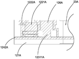
- 2C is a partial cross-sectional view of a side view camera module of an endoscope head assembly of an endoscope in accordance with a second preferred embodiment of the present invention.
- 3A is an exploded view of an endoscope in accordance with a third preferred embodiment of the present invention.
- Figure 3B is a cross-sectional view of an endoscope in accordance with a third preferred embodiment of the present invention.
- Figure 3C is a perspective view of an endoscope head assembly of an endoscope in accordance with a third preferred embodiment of the present invention.
- 3D is an exploded view of an endoscope head assembly of an endoscope in accordance with a third preferred embodiment of the present invention.
- 3E is a further exploded view of an endoscope head assembly of an endoscope in accordance with a third preferred embodiment of the present invention.
- Figure 3F is a cross-sectional view of an endoscope head assembly of an endoscope in accordance with a third preferred embodiment of the present invention.
- an endoscope according to a first preferred embodiment of the present invention is used for connection to a display device for facilitating effective internal conditions of an object, complicated pipeline abnormalities, and internal processing of a cast workpiece. Detailed inspection of the situation and wear and tear of parts and components.
- the endoscope includes an endoscope head assembly 10, a connecting catheter 20, a handle member 30, and an adapter unit 40.
- the adapter unit 40 is coupled to the endoscope head assembly 10 and the handle member 30 through the connecting catheter 20, respectively.
- the display device After being obtained, the display device is transmitted to the display device connected to the handle member 30 via the adapter unit 40, so as to facilitate the knowledge of the condition of the object to be detected.
- the handle member 30 is used to support the house
- the connecting catheter 20 and the adapting unit 40 are described and can also be held by an operator or an automated robotic arm to enable the endoscope to perform an internal visual inspection.
- the endoscope head assembly 10 includes a front view camera module 11.
- the main view camera module 11 includes a main view body 111, a front view lens unit 112, a main view illumination unit 113, and a main view photo unit 114.
- the main view camera module 11 may be a fixed focus camera device or a zoom camera device.
- the main-view body 111 forms a receiving cavity 1111 of a bilateral opening, wherein the main-view lens unit 112, the main-view lighting unit 113 and the main-view photosensitive unit 114 are respectively disposed inside the receiving cavity 1111.
- the main-view illumination unit 113 is disposed adjacent to the main-view lens unit 112 such that the main-view illumination unit 113 can provide illumination to the brightness required for the detection behavior while providing a light source to the main view.
- the lens unit 112 is such that the detection behavior is performed with sufficient brightness, and the main-view lens unit 112 can obtain the clear internal image.
- the main-view light-receiving unit 114 is disposed behind the main-view lens unit 112, such that the main-view light-receiving unit 114 can directly obtain the internal image through the main-view lens unit 112, and then transfer the image through the transfer.
- Unit 40 transmits the internal image to the display device. It is worth mentioning that the main view body 111 can be made of metal material or plastic material according to the needs of use.
- the front view camera module 11 is connected to the connection duct 20 for acquiring the image information of the endoscope endoscope.
- the outer diameter of the endoscope head assembly 10 is 3.8 millimeters (mm) or less, so as to detect the inside of the smaller aperture, such as the aperture of some engines is only 5 millimeters (mm), the present invention can be easily and easily Pass and detect the internal conditions of the engine.
- the front view lens unit 112 includes a front view lens 1121, a front view mirror mount 1122, a main view voice coil motor (which may not be present in the fixed focus module), and other possible components such as color filters.
- the main mirror mount 1122 supports the front view lens 1121.
- the main view ring coil motor is connected to the main view lens 1121 to adjust the focal length or magnification of the main view lens 1121, so that the main view lens 1121 can be moved while maintaining the most appropriate focus effect.
- Ability
- the main-view photosensitive unit 114 includes a main-view photosensitive chip 1141, and a main-view wiring board 1142, wherein the main-view photosensitive chip 1141 is located behind the main-view lens 1121 for imaging.
- the main view circuit board 1142 is configured to transmit image data acquired by the endoscope head assembly 10 to the display device by being connected to the switching unit 40.
- the main view illumination unit 113 includes a front view light source 1131 and a front view mount 1132.
- the front view assembly 1132 supports the front view light source 1131.
- the main view assembly 1132 may be assembled or integrally formed with the main mirror mount 1122. In the example shown in the figures, the two are integrally formed, or the front view mount 1132 and the main mirror mount 1122 may be formed into one.
- An integral mirror mount, and the front view light source 1131 is supported and fixed to the front view mount 1132.
- the main-view light source 1131 includes a light-emitting element 11311 and a circuit board 11312, wherein the circuit board 11312 connects the light-emitting element 11311 to the main-view circuit board 1142 for controlled supply.
- the light-emitting element 11311 can be implemented as an LED cold light source.
- the circuit board 11312 can be implemented as a flexible circuit board such as a bendable FPC.
- FPC is a kind of flexible circuit board; the general circuit board is to coat copper foil on a layer of glass fiber with basic thickness and hardness.
- Flexible circuit boards are flexible, which saves space and makes electronic products more suitable for light, thin and short directions.
- the flexible wiring board 11312 is bent to mount the light emitting element 11311, and the light emitting element 11311 and the front view lens 1121 are arranged toward the same front side direction.
- the main view camera module 11 includes a front view sealing lens 115 that is assembled on the upper surface of the front view lens unit 112 and the inside of the main view body 111 for protecting the main view lens unit 112.
- the main-view illumination unit 113, and the main-view photosensitive unit 114, while avoiding other substances directly contacting the main-view lens unit 112, the main-view illumination unit 113, and the main-view photosensitive unit 114 The service life of the endoscope head assembly 10 is described.
- the front view sealing lens 115 can be made of glass material or plastic material.
- a V-shape 101 represents the angle of view of the main-view lens 1121.
- the connecting catheter 20 includes a receiving end 21 and an outer end 22 at its distal and proximal ends, respectively, wherein the insertion end 21 is assemblably connected The endoscopic head assembly 10, wherein the outer end portion 22 is operatively coupled to the handle member 30.
- the connecting duct 20 forms a connecting passage 23 which extends integrally within the insertion end portion 21 and the outer end portion 22, so that the switching unit 40 can be installed
- the connecting channel 23 serves to protect the switching unit 40.
- the connecting catheter 20 may be a rigid material or a soft material according to the needs of the implementation to increase the utility of the endoscope.
- the connecting duct 20 can also be made of metal material or plastic material according to the requirements of use.
- the adapter unit 40 includes a minimum of one wire 41, and a rotary interface member 42 located at an end face 31 of the handle member 30.
- the wire 41 is located in the connecting channel 23 and is connected to the front view circuit board 1142 and the interface element 42 for transmission
- the image information obtained by the endoscope head assembly 10 is coupled to the display device, wherein the display device is coupled to the interface element of the handle member 30.
- the present invention also provides an endoscope detection operation method, which includes the following steps:
- An switching unit 40 transmits the internal image obtained by the endoscope head assembly 10 to a display device.
- an endoscope according to a second preferred embodiment of the present invention is used for connection to a display device for convenient and effective internal conditions of an object, complicated pipeline abnormalities, and internal processing of a cast workpiece. Detailed inspection of the situation and wear and tear of parts and components.
- the endoscope includes an endoscope head assembly 10A, a connecting catheter 20A, a handle member 30A, and a minimum of one adapter unit 40A.
- the adapter unit 40A is coupled to the endoscope head assembly 10A and the grip member 30A through the connecting catheter 20A, respectively.
- the display device when the display device is connected to the switching unit 40A at one end of the handle member 30A, and the endoscope head assembly 10A enters a to-be-detected object, an image information passes through the endoscope head assembly 10A. After being acquired, the display device is transmitted to the display device connected to the handle member 30A via the switching unit 40A, so as to facilitate the knowledge of the condition of the object to be detected.
- the grip member 30A is for supporting the connecting duct 20A and the adapting unit 40A, and can also be held by an operator or an automated robot arm, thereby enabling the endoscope to perform an internal inspection.
- the endoscope head assembly 10A includes a side view camera module 12A.
- the side view camera module 12A includes a side view body 121A, a side view lens unit 122A, a side view illumination unit 123A, and a side view photo unit 124A.
- the side view camera module 12A may be a fixed focus camera device or a zoom camera device.
- the side view body 121A is for supporting the side view lens unit 122A, the side view illumination unit 123A and the side view light unit 124A.
- the side view illumination unit 123A is disposed adjacent to the side view lens unit 122A such that the side view illumination unit 123A can provide illumination to the brightness required for the detection behavior while providing a light source to the side view
- the lens unit 122A enables sufficient brightness when the detection behavior is performed, and the side view lens unit 122A can obtain the clear internal image.
- the side view photosensitive unit 124A is disposed behind the side view lens unit 122A, such that the side view light receiving unit 124A can directly obtain the internal image via the side view lens unit 122A, and then transfer the image through the side view.
- Unit 40A transmits the internal image to the display device.
- the side view body 121A can be used according to the needs. It is made of metal or plastic materials.
- the side view body 121A can also be fabricated by a low pressure injection molding process to achieve a better sealing effect, reliability in a liquid environment can be ensured, and manufacturing costs can be reduced.
- the side view camera module 12A is connected to the connection duct 20A for acquiring the image information of the endoscope side.
- the outer diameter of the endoscope head assembly 10A is 3.8 millimeters (mm) or less so as to detect the inside of the smaller aperture, such as some engines having an aperture of only 5 millimeters (mm), the present invention can be easily and easily Pass and detect the internal conditions of the engine.
- the side view lens unit 122A includes a side view lens 1221A, a side view lens mount 1222A, a side view voice coil motor (which may not be present in the fixed focus module), and other possible components such as color filters.
- the side view mirror mount 1222A supports the side view lens 1221A.
- the side view voice coil motor is connected to the side view lens 1221A to adjust the focal length or magnification of the side view lens 1221A, so that the side view lens 1221A can be moved while maintaining the most appropriate focus effect.
- Ability is provided to the side view lens 1221A to adjust the focal length or magnification of the side view lens 1221A, so that the side view lens 1221A can be moved while maintaining the most appropriate focus effect.
- a side view lens mount 1222A supports the side view lens 1221A.
- the side view voice coil motor is connected to the side view lens 1221A to adjust the focal length or magnification of the side view lens 1221A, so that the side view lens 1221A can be moved while maintaining the most
- the side view photosensitive unit 124A includes a side view sensor chip 1241A and a side view picture board 1242A, wherein the side view sensor chip 1241A is located behind the side view lens 1221A for imaging.
- the side view circuit board 1242A is configured to transmit image data acquired by the endoscope head assembly 10A to the display device by being connected to the switching unit 40A.
- the side view illumination unit 123A includes a side view light source 1231A and a side view mount 1232A.
- the side view assembly 1232A supports the side view light source 1231A. It is worth mentioning that the side view assembly 1232A can be assembled or integrally formed with the side mirror mount 1222A, and in the example shown in the figure, the two are integrally formed.
- the side view light source 1231A includes a light emitting element 12311A coupled to the side view circuit board 1242A for controllably providing for the detection behavior and operation of the side view lens unit 122A. Illumination.
- the light-emitting element 12311A can be implemented as an LED cold light source.
- the side view camera module 12A includes a side view sealing lens 125A, a light guiding element 126A and a side view sealing cover 127A.
- the side view sealing lens 125A is assembled on the side of the side view lens unit 122A
- the light guiding element 126A is assembled on the upper side of the side view lighting unit 123A
- the side surface of the side view body 121A press-fits the side view sealing lens 125A and the light guiding element 126A for protecting the side view lens unit 122A, the side view lighting unit 123A, and the side view photosensitive unit 124A While avoiding other substances directly contacting the side view lens unit 122A, the side view illumination unit 123A, and the side view photosensitive unit 124A to extend the inner The life of the lens assembly 10A is seen.
- the light directing element 126A can be used to form a high efficiency and high uniformity light source to increase the efficiency of the side view illumination unit 123A.
- the side view sealing lens 125A can be made of glass material or plastic material.
- the light guiding element 126A may also be made of a glass material or a plastic material.
- the connecting conduit 20A includes an insertion end portion 21A and an outer end portion 22A at its distal end and proximal end, respectively, wherein the insertion end portion 21A is assemblably connected
- the connecting duct 20A forms a connecting passage 23A which integrally extends inside the insertion end portion 21A and the outer end portion 22A, so that the switching unit 40A can be installed
- the connecting channel 23A is for protecting the switching unit 40A.
- the connecting duct 20A may be a hard material or a soft material according to the needs of implementation, so as to increase the practicality of the endoscope.
- the connecting duct 20A can also be made of metal material or plastic material according to the requirements of use.
- the adapter unit 40A includes a minimum of one wire 41A, and a rotary interface member 42A located on an end face 31A of the handle member 30A.
- the wire 41A is located in the connecting channel 23A and is connected to the side view circuit board 1242A and the interface element 42A for transmitting the image information obtained by the endoscope head assembly 10A.
- an endoscope according to a third preferred embodiment of the present invention is used for connecting to an upper computer for convenient and effective internal conditions of the object, complicated pipeline abnormalities, and casting of the workpiece interior. Detailed inspection of the processing conditions and wear and tear of parts and components.
- the endoscope includes an endoscope head assembly 10B, a connecting catheter 20B, a grip member 30B, and a transfer unit 40B.
- the adapter unit 40B is coupled to the endoscope head assembly 10B and the grip member 30B through the connecting catheter 20B, respectively.
- the upper computer when the upper computer is connected to the switching unit 40B at one end of the handle member 30B, and the endoscope head assembly 10B enters a to-be-detected object, an image information or an image signal passes through the inside.
- the oscillating lens assembly 10B is transmitted to the upper computer connected to the grip member 30B via the adapting unit 40B, so as to directly and conveniently know the condition of the object to be detected.
- the grip member 30B is for supporting the connecting duct 20B and the adapting unit 40B, and can also be held by an operator or an automated robot arm, thereby enabling the endoscope to perform an internal view inspection. jobs.
- the upper computer can be a computer, a television, a monitor, a display device, and the like.
- the endoscope head assembly 10B includes a front view camera module 11B and a side view camera module 12B.
- a front view funnel shape 101B on the drawing is a schematic view of the front view camera module 11B.
- the side view funnel shape 102B on the drawing is a schematic view of the side view camera module 12B.
- the main view camera module 11B includes a main view body 111B, a front view lens unit 112B, a main view illumination unit 113B, and a main view photo unit 114B.
- the main view camera module 11B may be a fixed focus camera device or a zoom camera device.
- the main view body 111B forms a accommodating cavity 1111B of a bilateral opening, which accommodates the main view lens unit 112B, the main view illumination unit 113B and the main view photo unit 114B.
- the main-view illumination unit 113B is disposed adjacent to the main-view lens unit 112B, such that the main-view illumination unit 113B can provide illumination to the brightness required for the detection behavior while providing a light source to the main view.
- the lens unit 112B enables sufficient brightness when the detection behavior is performed, and the main looking lens unit 112B can obtain the clear internal image.
- the main-view photo-sensing unit 114B is disposed behind the main-view lens unit 112B, such that the main-view photo-sensing unit 114B can directly obtain the internal image through the main-view lens unit 112B, and then transfer the image through the transfer.
- Unit 40B transmits the internal image to the host computer.
- the main view body 111B can be made of a metal material or a plastic material according to the use requirements.
- the side view camera module 12B includes a side view body 121B, a side view lens unit 122B, a side view illumination unit 123B, and a side view photo unit 124B.
- the side view camera module 12B may be a fixed focus camera device or a zoom camera device.
- the side view body 121B is for supporting the side view lens unit 122B, the side view illumination unit 123B and the side view light unit 124B.
- the side view illumination unit 123B is disposed adjacent to the side view lens unit 122B such that the side view illumination unit 123B can provide illumination to the brightness required for the detection behavior while providing a light source to the side view
- the lens unit 122B allows the detection behavior to be performed with sufficient brightness, and the side view lens unit 122B can obtain a clear internal image.
- the side view photosensitive unit 124B is disposed behind the side view lens unit 122B, such that the side view light receiving unit 124B can directly obtain the internal image via the side view lens unit 12B, and then transfer the image through the side view.
- Unit 40B transmits the internal image to the display device.
- the side view body 121B can be made of a metal material or a plastic material according to the use requirements. Alternatively, the side view body 121B can also be fabricated by a low pressure injection molding process to achieve a better sealing effect, reliability in a liquid environment can be ensured, and manufacturing costs can be reduced.
- the endoscope head assembly 10B is coupled to the connection catheter 20B for obtaining the image information of the front end of the endoscope.
- the outer diameter of the endoscope head assembly 10B is 3.8 millimeters (mm) or less so as to detect the inside of the smaller aperture, such as the aperture of some engines is only 5 millimeters (mm), and the present invention can be easily and easily Pass and detect the internal conditions of the engine.
- the front view lens unit 112B includes a front view lens 1121B, a front view lens mount 1122B, a main view voice coil motor (there may be no such components in the fixed focus module), and other possible Parts such as color filters.
- the main mirror mount 1122B supports the main looking lens 1121B. In other words, the main looking lens 1121B is fixed to the main mirror mount 1122B.
- the main view ring coil motor is connected to the main view lens 1121B to adjust the focal length or magnification of the main view lens 1121B, so that the main view lens 1121B can be moved while maintaining the most appropriate focus effect.
- Ability is connected to the main view lens 1121B to adjust the focal length or magnification of the main view lens 1121B, so that the main view lens 1121B can be moved while maintaining the most appropriate focus effect.
- the side view lens unit 122B includes a side view lens 1221B, a side view lens mount 1222B, a side view voice coil motor (which may not be present in the fixed focus module), and other possible Parts such as color filters.
- the side mirror mount 1222B supports the side view lens 1221B.
- the side view lens 1221B is fixed to the side mirror mount 1222B.
- the side view voice coil motor is connected to the side view lens 1221B to adjust the focal length or magnification of the side view lens 1221B, so that the side view lens 1221B can be moved while maintaining the most appropriate focus effect.
- Ability is connected to the side view lens 1221B to adjust the focal length or magnification of the side view lens 1221B, so that the side view lens 1221B can be moved while maintaining the most appropriate focus effect.
- the main-view photosensitive unit 114B includes a main-view photosensitive chip 1141B and a main-view wiring board 1142B, wherein the main-view photosensitive chip 1141 is attached to the main-view wiring board 1142B and located at the The rear of the main lens 1121B is used for imaging.
- the main mirror mount 1122B and the front view lens 1121B are overlaid on the main view photoreceptor chip 1141B and assembled on the main view circuit board 1142B.
- the side view photosensitive unit 124B includes a side view photosensitive chip 1241B and a side view wiring board 1242B, wherein the side view photosensitive chip 1241B is attached to the side view wiring board 1242B and located at the The rear side of the side lens 1221B is used for imaging.
- the side view mirror holder 1222B and the side view lens 1221B are overlaid on the side view sensor chip 1241B and assembled on the side view circuit board 1242B.
- the front view circuit board 1142B and the side view circuit board 1242B are integrally formed by soldering to connect the front view camera module 11B and the side view camera module 12B. .
- the side view body 121B can be formed by low pressure injection molding to seal the exposed components and connect the front view camera module 11B and the side view camera module 12B to complete the assembly of the endoscope head assembly 10.
- the side view circuit board 1242B is connected Connected to the switching unit 40 to transmit image data acquired by the endoscope head assembly 10 to the upper computer.
- the primary view illumination unit 113B includes a front view light source 1131B and a front view mount 1132B.
- the front view assembly 1132B supports the front view light source 1131B.
- the front view light source 1131B is fixed to the front view mount 1132B.
- the front view assembly 1132B can be assembled or integrally formed with the main mirror mount 1122B. In the example shown in the figure, the two are integrally formed.
- the main-view light source 1131B includes a front view light-emitting element 11311B and a circuit board 11312B, wherein the circuit board 11312B connects the front view light-emitting element 11311B to the main-view circuit board 1142B for being used by Controlling the illumination required to perform the detection behavior and the operation of the main looking lens unit 112B is provided.
- the main-view light-emitting element 11311B can be implemented as an LED cold light source.
- the circuit board 11312B can be implemented as a flexible circuit board such as a bendable FPC.
- FPC is a kind of flexible circuit board; the general circuit board is to coat copper foil on a layer of glass fiber with basic thickness and hardness. Flexible circuit boards are flexible, which saves space and makes electronic products more suitable for light, thin and short directions.
- the side view illumination unit 123B includes a side view light source 1231B and a side view mount 1232B.
- the side view assembly 1232B supports the side view light source 1231B.
- the side view assembly 1232B can be assembled or integrally formed with the side mirror mount 1222B, and in the example shown in the figure, the two are integrally formed.
- the side view light source 1231B includes a side view light emitting element 12311B attached to the side view circuit board 1242B for controlled supply of the detection behavior and the side view lens unit 122B operation.
- the required illumination
- the side view light-emitting element 12311B can be implemented as an LED cold light source.
- the front view camera module 11B includes a front view sealing lens 115B that is assembled in front of the front view lens unit 112B and inside the main view body 111B for protecting the main view lens unit 112B.
- the main sealing lens 115B can be made of glass material or transparent plastic material.
- the side view camera module 12B includes a side view sealing lens 125B, a light guiding element 126B and a side view sealing cover 127B.
- the side view sealing lens 125B is assembled on the side of the side view lens unit 122B
- the light guiding element 126B is assembled on the side of the side view lighting unit 123B
- the side view sealing cover 127B press-fits the side view sealing lens 125B and the light guiding element 126B on the side of the side view body 121B for protecting the side view lens unit 122B, the side view lighting unit 123B, and the side view photosensitive unit 124B while avoiding other substances directly contacting the side view lens unit 122B, the side view illumination unit 123B, and the side view photosensitive unit 124B to extend the endoscope head assembly 10B The service life.
- the light directing element 126B can be used to form a high efficiency and high uniformity light source to increase the efficiency of the side view illumination unit 123B.
- the side view sealing lens 125B can be made of glass material or plastic material.
- the light guiding element 126B may also be made of a glass material or a transparent plastic material.
- the connecting conduit 20B includes a receiving end portion 21B and an outer end portion 22B at its distal end and proximal end, respectively, wherein the insertion end portion 21B is assemblably connected
- the connecting duct 20B forms a connecting passage 23B which integrally extends inside the insertion end portion 21B and the outer end portion 22B, so that the switching unit 40B can be installed
- the connecting channel 23B is for protecting the switching unit 40B.
- the connecting duct 20B may be a hard material or a soft material according to the needs of implementation, so as to increase the practicability of the endoscope.
- the connecting duct 20B can also be made of metal material or plastic material according to the requirements of use.
- the adapter unit 40B includes a minimum of one wire 41B, and a rotary interface member 42B located at an end face 31B of the handle member 30B.
- the wire 41B passes through the connecting channel 23B and is connected to the side view circuit board 1242B and the interface element 42B for transmitting the image information obtained by the endoscope head assembly 10B to The upper machine, wherein the upper machine is connected to the transfer interface element 42B of the handle member 30.
- the interface component 42B can be implemented as a USB interface, a Micro USB interface, an AV interface, an HDMI interface, or the like.
- the present invention also provides a method of manufacturing an endoscope, comprising the steps of:
- a front view camera module 11B of an endoscope head assembly 10B and a side view camera module 12B of the endoscope head assembly 10B are assembled and integrated into one body;
- An outer end portion 22B of the connecting duct 20B is coupled to a grip member 30B such that a swivel interface member 42B of the adapting unit 40 is located at an end surface of the grip member 30B.
- the main-view camera module 11B further includes the following steps:
- a main view lens 1121B is attached to a main mirror mount 1122B;
- the main view light source 1131B is disposed on a front view assembly 1132B, and the main view lens mount 1122B is located above the main view photo chip 1141B;
- a front view sealing lens 115B is disposed to the front of a main view body 111B;
- the device formed by the above steps is placed into a receiving chamber in the main body 111B.
- the side view camera module 12B may further include the following steps:
- the side view lens 1221B of the side view lens unit 122B is disposed to the side view lens mount 1222B of the side view lens unit 122B;
- the side view lens holder 1222B is pressed against the side view circuit board 1242B such that the side view lens 1221B is positioned above the side view light sensing chip 1241B while the side view assembly seat 1232B is pressed against the side view.
- the side view sealing lens 125B is assembled above the side view lens unit 122B while assembling a light guiding element 126B above the side view light source 1231B of the side view illumination unit 123B, and The side view sealing lens 125B and the light guiding element 126B are press-fitted via the side view sealing cover 127B;
- the side view body 121B is formed to cover the components of the side view camera module 12B through the low pressure injection molding process, and is connected to the main view camera module 11B.
Landscapes
- Physics & Mathematics (AREA)
- Astronomy & Astrophysics (AREA)
- General Physics & Mathematics (AREA)
- Optics & Photonics (AREA)
- Endoscopes (AREA)
- Engineering & Computer Science (AREA)
- Multimedia (AREA)
- Instruments For Viewing The Inside Of Hollow Bodies (AREA)
Abstract
一种内窥镜,包括摄像组件、连接导管(20B)、握柄部件(30B)和转接单元(40B)。摄像组件包括主视摄像模组(11B)和侧视摄像模组(12B)。内窥镜外径3.8mm,直径微小,可以检测小孔径内部情况,并且可以同时检测内窥镜前端和侧面情况,在不用弯折内窥镜的情况下全视角检测,使得检测过程更全面和方便。
Description
本发明涉及一内窥镜,特别涉及一微小内窥镜,以用于检测各种受限微小空间,如在工业领域上,可用于检测不易拆解物品的内部。在医疗领域上,可使用患者将承受相对较小的不适。
内窥镜是一种光学仪器,从应用方面可分为医疗用途和工业用途。在医疗用途上,是将医疗内窥镜由人体体外进入人体体内,以用于对人体体内进行检查、取样、治疗。特别地是,当医疗内窥镜被用于进行医疗手术时,相对于传统的手术治疗方式,使用内窥镜手术造成的伤口相对于使用传统手术治疗的伤口细微。因此,使用内窥镜进行医疗检查或手术时,不但可以减少了手术的创伤性,同时可以增加医疗上的精确性和安全性,进而让病患对于医疗的治疗接受程度大为增加。在工业用途上,是一种利用纤维光学和光学、精密器械相结合的新型光学仪器,是针对工业,像是机械制造、造船、航空、发电、石化、交通、冶金等的检测或维修,其作为直观且无损的检测工具,通过摄像头显示的方式检测肉眼无法直接观测的地方,可对被检测对象的内部缺陷进行视觉定性检查和定量测量等检测工作。
目前在现今工业内窥镜若依其外观材质可分为软管内窥镜和硬管内窥镜两大类,若依成像原理分类可分为电子内窥镜、光导纤维内窥镜、光学内窥镜,若依光源种类可分为高频荧光灯内窥镜、光纤卤素灯内窥镜、LED内窥镜,若依用途分类则可分为视频电子内窥镜、便携式内窥镜、电子内窥镜、造内窥镜、管道内窥镜、发动机内窥镜、目视内窥镜、高温内窥镜、火焰内窥镜、微孔内窥镜、孔探仪等。
然而,现今工业用视频镜型内窥镜一般直径较大,在工业应用领域的小、微型空间中的应用是受到限制。即便是传统直杆镜和光纤镜虽然直径相对较小,但是只能输出光信号,不能直接输出视频图像电信号以致使用效率低,并且光
源通过光纤等介质传送时,光能量大量损耗,最终光源亮度低、光线集中以致光照范围狭小,照明效果无法达到本发明中的照明效果。
发明内容
本发明的主要目的在于提供一内窥镜,其中以用于检测各种受限微小空间,如在工业领域上,可以用于检测一些小孔径的内部。在医疗领域上,因所述内窥镜微小,故使得当所述内窥镜在用于医疗行为时,使用患者将承受相对较小的不适。
本发明的另一目的在于提供一内窥镜,其中包括主视摄像模组和一侧视摄像模组,所述主视摄像模组可以直接地检测所述内窥镜的前端情况,所述侧视摄像模组可以方便检测所述内窥镜的侧面情况,在可以不用弯折内窥镜的情况下进行全面检测,使得整个检测过程更全面和方便。
本发明的另一目的在于提供一内窥镜,其中采用低压注塑密封工艺,使所述内窥镜的密封效果更好,在液体环境使用时可以有更佳的可靠性,并且可以降低所述内窥镜的制造成本。
本发明的另一目的在于提供一内窥镜,以用于捕捉到清晰明亮的图像,超强的性能与绝对的便携性达到完美的统一,并融合了最新的计算机数字存储处理技术,成为检测领域解决质量及安全问题不可缺少的重要工具。
为达到以上目的,本发明提供一内窥镜摄像组件,其包括:
一主视摄像模组,其包括一主视感光单元,设置于所述主视感光单元前方的一主视镜头单元,和设置于所述主视镜头单元邻近位置的一主视照明单元,这样所述主视照明单元用于提供所述主视镜头单元和所述主视感光单元所需的亮度;和
一侧视摄像模组,其设置于所述主视摄像模组后方,并且包括一侧视感光单元,设置于一侧视感光单元前方的一侧视镜头单元,和设置于所述侧视镜头单元邻近位置的一侧视照明单元,这样所述侧视照明单元以用于提供所述侧视镜头单元和所述侧视感光单元所需的亮度。
在一个实施例中,所述主视感光单元包括电性连接的一主视感光芯片和一主视线路板,所述侧视感光单元包括电性连接的一侧视感光芯片和一侧视线路板,其中所述主视线路板位于所述侧视线路板的端侧并且沿着互相垂直的方向
布置。
在一个实施例中,所述侧视线路板和所述主视线路板相焊接从而形成一整体线路板。
在一个实施例中,所述主视照明单元包括一主视发光元件以及一软性线路板,其中所述主视发光元件安装于所述软性线路板并且所述软性线路板电性连接于所述主视线路板并且经弯折后使所述主视发光元件和所述主视镜头单元朝向同样的主视方向地布置。
在一个实施例中,所述侧视镜头单元包括一侧视镜头和一侧视镜座,所述侧视照明单元包括一侧视光源和一侧视组装座,所述侧视光源组装于所述侧视线路板,所述侧视组装座用于容纳和定位所述侧视光源,并且和所述侧视镜座相组装或一体成形。
在一个实施例中,其还包括一主视本体以及一侧视本体,所述主视主体用于容纳所述主视摄像模组,所述侧视本体用于容纳所述侧视摄像模组。
在一个实施例中,所述侧视本体由注塑工艺形成并且在不影响所述侧视摄像模组的摄像功能的同时密封所述侧视摄像模组。
在一个实施例中,所述主视摄像模组还包括由一主视密封镜片,其组装于所述主视镜头单元前方。
在一个实施例中,所述侧视摄像模组还包括一侧视密封镜片,一导光元件以及一侧视密封盖,其中所述侧视密封镜片组装于所述侧视镜头单元的上面,所述导光元件组装于所述侧视照明单元的上面并实现密封,并且经由所述侧视密封盖压合固定所述侧视密封镜片和导光元件。
在一个实施例中,所述主视本体是由金属材料制成。
在一个实施例中,所述主视照明单元和所述侧视照明单元是基于冷LED的照明单元。
在一个实施例中,所述主视密封镜片是玻璃材料所制成或透明塑胶材料所制成。
在一个实施例中,所述侧视密封镜片和所述导光元件是玻璃材料或透明塑胶材料所制成。
在一个实施例中,所述内窥镜摄像组件的整体外径小于等于3.8毫米。
根据本发明的另外一方面,本发明提供一内窥镜,以用于取得一影像资讯并传输至一上位机,其包括上述内窥镜摄像组件;和
一连接导管,其包括一置入端部和一外部端部,其中所述置入端部可组装地连接所述内窥镜摄像组件;
一转接单元,其穿过所述连接导管连接于所述内窥镜摄像组件,并适合于连接于一上位机;以及
一握柄部件,其用于连接所述连接导管的所述外部端部和支撑所述转接单元,并且供操作者或自动化机械臂握持,从而使所述内窥镜得以进行内视的检查工作。
在一个实施例中,所述连接导管形成一连接通道,其一体地延伸于所述置入端部和所述外部端部之内,以用于装所述转接单元装置于所述连接通道去保护所述转接单元。
在一个实施例中,所述转接单元包括最少一导线,和位于所述握柄部件的一端面的一转接口元件,所述导线穿过所述连接通道内,并且连接于所述侧视线路板和所述转接口元件,以用于传送经所述内窥镜摄像组件取得的所述影像资讯到所述上位机,其中所述上位机连接于位在所述握柄部件的所述转接口元件。
在一个实施例中,所述转接口元件选自USB接口、Micro USB接口、AV接口、HDMI接口中的一种或几种
根据本发明的另外一方面,本发明还提供一内窥镜的制造方法,其包括如下步骤:
将一内窥镜头组件的一主视摄像模组和所述内窥镜头组件的一侧视摄像模组组装连结成一体;
将一转接单元穿过一连接导管,使所述转接单元的一端连接所述内窥镜头组件;以及
将所述连接导管的一外部端部接合于一握柄部件,使得所述转接单元的一转接口元件位于所述握柄部件的一端面。
根据本发明的一个实施例,在上述方法中,所述主视摄像模组进一步的包括步骤:
将一主视发光元件和一线路板贴合形成一主视光源;
将一主视感光芯片贴附于一主视线路板形成一主视感光单元;
将所述主视光源的所述线路板焊接于所述形成一主视感光单元的所述主视线路板;
将一主视镜头装置至一主视镜座;
将所述主视光源装置于一主视组装座,同时所述主视镜座位于所述主视感光芯片的上方,所述主视镜座和所述主视组装座形成一整体镜座;
将一主视密封镜片装置至一主视本体的前方;以及
根据本发明的一个实施例,在上述方法中,所述侧视摄像模组进一步的包括步骤:
将一侧视光源的一侧视发光元件其贴附于一侧视线路板;
将一侧视感光单元的一侧视感光芯片贴附于所述侧视感光单元的所述侧视线路板;
将一侧视镜头单元的一侧视镜头装置到一侧视镜头单元的一侧视镜座;
将所述侧视镜座压合于所述侧视线路板,使所述侧视镜头位于所述侧视感光芯片的上方,同时将一侧视组装座压合于所述侧视发光元件的上方;
一侧视密封镜片组装于所述侧视镜头单元的上方,同时将一导光元件组装于一侧视照明单元的所述侧视光源的上方,并且经由一侧视密封盖压合固定所述侧视密封镜片和导光元件;
将所述主视摄像模组的所述主视感光单元的所述主视线路板焊接到所述侧视摄像模组的所述侧视感光单元的所述侧视线路板;以及
经由低压注塑密封工艺形成一侧视本体用以包覆所述侧视摄像模组的元件,同时连接所述主视摄像模组。
图1A是根据本发明的第一个优选实施例的一内窥镜的爆炸视图。
图1B是根据本发明的第一个优选实施例的一内窥镜的剖视图。
图1C是根据本发明的第一个优选实施例的一内窥镜的一内窥镜头组件的一主视摄像模组的爆炸视图。
图1D的是根据本发明的第一个优选实施例的一内窥镜的一内窥镜头组件的一主视摄像模组的剖视图。
图2A是根据本发明的第二个优选实施例的一内窥镜的爆炸视图。
图2B是根据本发明的第二个优选实施例的一内窥镜的一内窥镜头组件的一侧视摄像模组的爆炸视图。
图2C是根据本发明的第二个优选实施例的一内窥镜的一内窥镜头组件的一侧视摄像模组的局部剖视图。
图3A是根据本发明的第三个优选实施例的一内窥镜的爆炸视图。
图3B是根据本发明的第三个优选实施例的一内窥镜的剖视图。
图3C是根据本发明的第三个优选实施例的一内窥镜的一内窥镜头组件的透视图。
图3D是根据本发明的第三个优选实施例的一内窥镜的一内窥镜头组件的爆炸视图。
图3E是根据本发明的第三个优选实施例的一内窥镜的一内窥镜头组件的进一步的爆炸视图
图3F是根据本发明的第三个优选实施例的一内窥镜的一内窥镜头组件的剖视图。
以下描述用于揭露本发明以使本领域技术人员能够实现本发明。以下描述中的优选实施例只作为举例,本领域技术人员可以想到其他显而易见的变型。在以下描述中界定的本发明的基本原理可以应用于其他实施方案、变形方案、改进方案、等同方案以及没有背离本发明的精神和范围的其他技术方案。
如图1A至1D所示,是根据本发明第一优选实施例的一内窥镜,以用于连接于一显示设备,以方便有效的对物体内部情况、复杂管道异常情况、铸造工件内部加工情况及零部件工作磨损等情况进行细致全面的检查。所述内窥镜包括一内窥镜头组件10,一连接导管20,一握柄部件30以及一转接单元40。所述转接单元40穿过所述连接导管20分别连接于所述内窥镜头组件10和所述握柄部件30。这样当所述显示设备连接于位于所述握柄部件30一端的所述转接单元40,且所述内窥镜头组件10进入一待检测物时,一影像资讯经所述内窥镜头组件10取得后经由所述转接单元40传输到连接于所述握柄部件30的所述显示设备,以便于方便得知所述待检测物的情况。所述握柄部件30用于支撑所
述连接导管20和所述转接单元40,并且也可以供操作者或自动化机械臂握持,从而使所述内窥镜得以进行内视的检查工作。
根据本发明优选实施例,所述内窥镜头组件10包括一主视摄像模组11。所述主视摄像模组11包括一主视本体111,一主视镜头单元112,一主视照明单元113,以及一主视感光单元114。其中,所述主视摄像模组11可以是定焦摄像头装置,也可以是变焦摄像头装置。所述主视本体111形成双边开口的一容纳腔1111,其中所述主视镜头单元112,所述主视照明单元113和所述主视感光单元114分别被置于所述容纳腔1111内部。所述主视照明单元113设置邻近于所述主视镜头单元112,这样所述主视照明单元113可以提供照明给所述检测行为时所需的亮度,同时可供一光源给所述主视镜头单元112,使得所述检测行为进行时有足够的亮度,并且所述主视镜头单元112能够取得清晰的所述内部影像。所述主视感光单元114被设置于所述主视镜头单元112的后方,这样所述主视感光单元114经所述主视镜头单元112可以直接取得所述内部影像后,经由所述转接单元40将所述内部影像传送至所述显示设备。值得一提的是,所述主视本体111可以根据使用需求由金属材料或塑胶材料所制成。特别地,所述主视摄像模组11连接所述连接导管20,用于取得所述内窥镜前端的所述影像资讯。另外,所述内窥镜头组件10的外径是小于等于3.8毫米(mm),这样以便检测较小孔径的内部,像是一些发动机的孔径只有5毫米(mm),本发明可以轻松且容易的通过,并检测发动机内部情况。
所述主视镜头单元112包括一主视镜头1121,一主视镜座1122,一主视音圈马达(在定焦模组中可以没有此部件)以及其他可能的部件如滤色片。所述主视镜座1122支撑所述主视镜头1121。所述主视音圈马达连接于所述主视镜头1121,以便调整所述主视镜头1121的焦距或是放大倍率,能让所述主视镜头1121移动之际,还能保持最适当对焦效果的能力。
所述主视感光单元114包括一主视感光芯片1141,和一主视线路板1142,其中所述主视感光芯片1141位于所述主视镜头1121的后方,以用于成像。其中所述主视线路板1142通过连接于所述转接单元40从而得以将所述内窥镜头组件10获取的影像数据传送至所述显示设备。
所述主视照明单元113包括一主视光源1131,和一主视组装座1132。所述主视组装座1132支撑所述主视光源1131。值得一提的是,所述主视组装座
1132可以和所述主视镜座1122相组装或一体成形,在图中所示的例子中,两者一体成形,或者可以说所述主视组装座1132和所述主视镜座1122形成一个整体镜座,而所述主视光源1131支撑固定于所述主视组装座1132。特别地,所述主视光源1131包括一发光元件11311和一线路板11312,其中所述线路板11312将所述发光元件11311连接于所述主视线路板1142,以用于被控制地提供进行所述检测行为和所述主视镜头单元112操作时所需照度。特别一提的,所述发光元件11311可以实施为一LED冷光源。所述线路板11312可以实施为一软性线路板,像是可弯折FPC。其中FPC即为一种软性电路板;一般电路板是将铜箔加覆在一层玻璃纤维上,具基本厚度及硬度。软性电路板则具备可挠曲性,能有效的节省空间、使得电子产品更能符合轻薄短小的方向。所述软性线路板11312经弯折后用于安装所述发光元件11311,并且所述发光元件11311和所述主视镜头1121朝向相同的前侧方向地布置。
所述主视摄像模组11包括一主视密封镜片115,其组装于所述主视镜头单元112的上面和所述主视本体111的内部,以用于保护所述主视镜头单元112,所述主视照明单元113,和所述主视感光单元114,同时避免其它物质直接接触所述主视镜头单元112,所述主视照明单元113,和所述主视感光单元114以延长所述内窥镜头组件10的使用寿命。值得一提的是,所述主视密封镜片115可以是玻璃材料或塑胶材料所制成。值得一提的是,如图1A所示,一V形101表示所述主视镜头1121的视角。
在这个优选实施例中,更具体地,所述连接导管20在其远端和近端分别包括一置入端部21和一外部端部22,其中所述置入端部21可组装地连接所述内窥镜头组件10,其中所述外部端部22可组装地连接所述握柄部件30。值得一提的是,所述连接导管20形成一连接通道23,其一体地延伸于所述置入端部21和所述外部端部22之内,这样所述转接单元40可以被装置于所述连接通道23以用于保护所述转接单元40。另外,所述连接导管20根据实施的需要可以是硬性材质也可以是软性材质,以增加所述内窥镜的实用性。另外所述连接导管20亦可以根据使用上的要求是金属材质或塑胶材质所制成。
根据本发明优选实施例,所述转接单元40包括最少一导线41,和位于所述握柄部件30的一端面31的一转接口元件42。所述导线41位于所述连接通道23内,并且连接于所述主视线路板1142和所述转接口元件42,以用于传送经
所述内窥镜头组件10取得的所述影像资讯到所述显示设备,其中所述显示设备连接于位在所述握柄部件30的所述转接口元件。
另外,本发明还提供一内窥镜的检测操作方法,其包括如下步骤:
(A)将连接于一连接导管20的一内窥镜头组件10置入一待测物品内部;
(B)所述内窥镜头组件10取得所述待测物品的一内部影像;以及
(C)一转接单元40将所述内窥镜头组件10取得的所述内部影像传输至一显示装置。
如图2A至2C所示,是根据本发明第二优选实施例的一内窥镜,以用于连接于一显示设备,以方便有效的对物体内部情况、复杂管道异常情况、铸造工件内部加工情况及零部件工作磨损等情况进行细致全面的检查。所述内窥镜包括一内窥镜头组件10A,一连接导管20A,一握柄部件30A以及最少一转接单元40A。所述转接单元40A穿过所述连接导管20A分别连接于所述内窥镜头组件10A和所述握柄部件30A。这样当所述显示设备连接于位于所述握柄部件30A一端的所述转接单元40A,且所述内窥镜头组件10A进入一待检测物时,一影像资讯经所述内窥镜头组件10A取得后经由所述转接单元40A传输到连接于所述握柄部件30A的所述显示设备,以便于方便得知所述待检测物的情况。所述握柄部件30A用于支撑所述连接导管20A和所述转接单元40A,并且也可以供操作者或自动化机械臂握持,从而使所述内窥镜得以进行内视的检查工作。
根据本发明优选实施例,所述内窥镜头组件10A包括一侧视摄像模组12A。所述侧视摄像模组12A包括一侧视本体121A,一侧视镜头单元122A,一侧视照明单元123A,以及一侧视感光单元124A。其中,所述侧视摄像模组12A可以是定焦摄像头装置,也可以是变焦摄像头装置。所述侧视本体121A用于支撑容纳所述侧视镜头单元122A,所述侧视照明单元123A和所述侧视感光单元124A。所述侧视照明单元123A设置邻近于所述侧视镜头单元122A,这样所述侧视照明单元123A可以提供照明给所述检测行为时所需的亮度,同时可供一光源给所述侧视镜头单元122A,使得所述检测行为进行时有足够的亮度,并且所述侧视镜头单元122A能够取得清晰的所述内部影像。所述侧视感光单元124A被设置于所述侧视镜头单元122A的后方,这样所述侧视感光单元124A经所述侧视镜头单元122A可以直接取得所述内部影像后,经由所述转接单元40A将所述内部影像传送至所述显示设备。值得一提的是,所述侧视本体121A可以根据使用需
求由金属材料或塑胶材料所制成。或者所述侧视本体121A亦可以采用低压注塑密封工艺所制成,以达到较好的密封性效果,在液体环境中的可靠性可以得到保障,同时可降低制造成本。特别地,所述侧视摄像模组12A连接所述连接导管20A,用于取得所述内窥镜侧部的所述影像资讯。另外,所述内窥镜头组件10A的外径是小于等于3.8毫米(mm),这样以便检测较小孔径的内部,像是一些发动机的孔径只有5毫米(mm),本发明可以轻松且容易的通过,并检测发动机内部情况。
所述侧视镜头单元122A包括一侧视镜头1221A,一侧视镜座1222A,一侧视音圈马达(在定焦模组中可以没有此部件)以及其他可能的部件如滤色片。所述侧视镜座1222A支撑所述侧视镜头1221A。所述侧视音圈马达连接于所述侧视镜头1221A,以便调整所述侧视镜头1221A的焦距或是放大倍率,能让所述侧视镜头1221A移动之际,还能保持最适当对焦效果的能力。
所述侧视感光单元124A包括一侧视感光芯片1241A,和一侧视线路板1242A,其中所述侧视感光芯片1241A位于所述侧视镜头1221A的后方,以用于成像。其中所述侧视线路板1242A通过连接于所述转接单元40A从而得以将所述内窥镜头组件10A获取的影像数据传送至所述显示设备。
所述侧视照明单元123A包括一侧视光源1231A,和一侧视组装座1232A。所述侧视组装座1232A支撑所述侧视光源1231A。值得一提的是,所述侧视组装座1232A可以和所述侧视镜座1222A相组装或一体成形,在图中所示的例子中,两者一体成形。特别地,所述侧视光源1231A包括一发光元件12311A,其连接于所述侧视线路板1242A,以用于被控制地提供进行所述检测行为和所述侧视镜头单元122A操作时所需照度。特别一提的,所述发光元件12311A可以实施为一LED冷光源。
所述侧视摄像模组12A包括一侧视密封镜片125A,一导光元件126A以及一侧视密封盖127A。其中所述侧视密封镜片125A组装于所述侧视镜头单元122A的上面,所述导光元件126A组装于所述侧视照明单元123A的上面,并且经由所述侧视密封盖127A在所述侧视本体121A的侧面压合固定所述侧视密封镜片125A和导光元件126A,以用于保护所述侧视镜头单元122A,所述侧视照明单元123A,和所述侧视感光单元124A,同时避免其它物质直接接触所述侧视镜头单元122A,所述侧视照明单元123A,和所述侧视感光单元124A以延长所述内
窥镜头组件10A的使用寿命。另外,所述导光元件126A可用于形成高效率与高均匀性光源,以提高所述侧视照明单元123A的效率。值得一提的是,所述侧视密封镜片125A可以是玻璃材料或塑胶材料所制成。所述导光元件126A亦可以是玻璃材料或塑胶材料所制成。
在这个优选实施例中,更具体地,所述连接导管20A在其远端和近端分别包括一置入端部21A和一外部端部22A,其中所述置入端部21A可组装地连接所述内窥镜头组件10A,其中所述外部端部22A可组装地连接所述握柄部件30A。值得一提的是,所述连接导管20A形成一连接通道23A,其一体地延伸于所述置入端部21A和所述外部端部22A之内,这样所述转接单元40A可以被装置于所述连接通道23A以用于保护所述转接单元40A。另外,所述连接导管20A根据实施的需要可以是硬性材质也可以是软性材质,以增加所述内窥镜的实用性。另外所述连接导管20A亦可以根据使用上的要求是金属材质或塑胶材质所制成。
根据本发明优选实施例,所述转接单元40A包括最少一导线41A,和位于所述握柄部件30A的一端面31A的一转接口元件42A。所述导线41A位于所述连接通道23A内,并且连接于所述侧视线路板1242A和所述转接口元件42A,以用于传送经所述内窥镜头组件10A取得的所述影像资讯到所述显示设备,其中所述显示设备连接于位在所述握柄部件30A的所述转接口元件。
如图3A至图3F所示,是根据本发明第三优选实施例的一内窥镜,以用于连接于一上位机,以方便有效的对物体内部情况、复杂管道异常情况、铸造工件内部加工情况及零部件工作磨损等情况进行细致全面的检测。所述内窥镜包括一内窥镜头组件10B,一连接导管20B,一握柄部件30B以及一转接单元40B。所述转接单元40B穿过所述连接导管20B分别连接于所述内窥镜头组件10B和所述握柄部件30B。这样当所述上位机连接于位于所述握柄部件30B一端的所述转接单元40B,且所述内窥镜头组件10B进入一待检测物时,一影像资讯或一图像信号经所述内窥镜头组件10B取得后经由所述转接单元40B传输到连接于所述握柄部件30B的所述上位机,以便于直接方便得知所述待检测物的情况。另外,所述握柄部件30B用于支撑所述连接导管20B和所述转接单元40B,并且也可以供操作者或自动化机械臂握持,从而使所述内窥镜得以进行内视的检查工作。值得一提的是,所述上位机可以是计算机、电视机、监视器、显示装置,以及其相类似的设备装置。
根据本发明优选实施例,所述内窥镜头组件10B包括一主视摄像模组11B和一侧视摄像模组12B。如图3C所示,图面上一主视漏斗形状101B为所述主视摄像模组11B的视角示意图。图面上一侧视漏斗形状102B为所述侧视摄像模组12B的视角示意图。
所述主视摄像模组11B包括一主视本体111B,一主视镜头单元112B,一主视照明单元113B,以及一主视感光单元114B。其中,所述主视摄像模组11B可以是定焦摄像头装置,也可以是变焦摄像头装置。所述主视本体111B形成双边开口的一容纳腔1111B,其容纳所述主视镜头单元112B,所述主视照明单元113B和所述主视感光单元114B。所述主视照明单元113B设置邻近于所述主视镜头单元112B,这样所述主视照明单元113B可以提供照明给所述检测行为时所需的亮度,同时可供一光源给所述主视镜头单元112B,使得所述检测行为进行时有足够的亮度,并且所述主视镜头单元112B能够取得清晰的所述内部影像。所述主视感光单元114B被设置于所述主视镜头单元112B的后方,这样所述主视感光单元114B经所述主视镜头单元112B可以直接取得所述内部影像后,经由所述转接单元40B将所述内部影像传送至所述上位机。值得一提的是,所述主视本体111B可以根据使用需求由金属材料或塑胶材料所制成。
根据本发明优选实施例,所述侧视摄像模组12B包括一侧视本体121B,一侧视镜头单元122B,一侧视照明单元123B,以及一侧视感光单元124B。其中,所述侧视摄像模组12B可以是定焦摄像头装置,也可以是变焦摄像头装置。所述侧视本体121B用于支撑容纳所述侧视镜头单元122B,所述侧视照明单元123B和所述侧视感光单元124B。所述侧视照明单元123B设置邻近于所述侧视镜头单元122B,这样所述侧视照明单元123B可以提供照明给所述检测行为时所需的亮度,同时可供一光源给所述侧视镜头单元122B,使得所述检测行为进行时有足够的亮度,并且所述侧视镜头单元122B能够取得清晰的所述内部影像。所述侧视感光单元124B被设置于所述侧视镜头单元122B的后方,这样所述侧视感光单元124B经所述侧视镜头单元12B可以直接取得所述内部影像后,经由所述转接单元40B将所述内部影像传送至所述显示设备。值得一提的是,所述侧视本体121B可以根据使用需求由金属材料或塑胶材料所制成。或者所述侧视本体121B亦可以采用低压注塑密封工艺所制成,以达到较好的密封性效果,在液体环境中的可靠性可以得到保障,同时可降低制造成本。
特别地,所述内窥镜头组件10B连接所述连接导管20B,用于取得所述内窥镜前端的所述影像资讯。另外,所述内窥镜头组件10B的外径是小于等于3.8毫米(mm),这样以便检测较小孔径的内部,像是一些发动机的孔径只有5毫米(mm),本发明可以轻松且容易的通过,并检测发动机内部情况。
根据本发明优选实施例,所述主视镜头单元112B包括一主视镜头1121B,一主视镜座1122B,一主视音圈马达(在定焦模组中可以没有此部件)以及其他可能的部件如滤色片。所述主视镜座1122B支撑所述主视镜头1121B。换句话说,所述主视镜头1121B固定于所述主视镜座1122B上。所述主视音圈马达连接于所述主视镜头1121B,以便调整所述主视镜头1121B的焦距或是放大倍率,能让所述主视镜头1121B移动之际,还能保持最适当对焦效果的能力。
根据本发明优选实施例,所述侧视镜头单元122B包括一侧视镜头1221B,一侧视镜座1222B,一侧视音圈马达(在定焦模组中可以没有此部件)以及其他可能的部件如滤色片。所述侧视镜座1222B支撑所述侧视镜头1221B。换句话说,所述侧视镜头1221B固定于所述侧视镜座1222B上。所述侧视音圈马达连接于所述侧视镜头1221B,以便调整所述侧视镜头1221B的焦距或是放大倍率,能让所述侧视镜头1221B移动之际,还能保持最适当对焦效果的能力。
根据本发明优选实施例,所述主视感光单元114B包括一主视感光芯片1141B和一主视线路板1142B,其中所述主视感光芯片1141贴附于所述主视线路板1142B并且位于所述主视镜头1121B的后方,以用于成像。特别地,所述主视镜座1122B和所述主视镜头1121B覆盖在所述主视感光芯片1141B上并组装在所述主视线路板1142B上。
根据本发明优选实施例,所述侧视感光单元124B包括一侧视感光芯片1241B和一侧视线路板1242B,其中所述侧视感光芯片1241B贴附于所述侧视线路板1242B并且位于所述侧视镜头1221B的后方,以用于成像。值得一提的是,所述侧视镜座1222B和所述侧视镜头1221B覆盖在所述侧视感光芯片1241B上并组装在所述侧视线路板1242B上。值得一提的是,通过焊接工艺进行所述主视线路板1142B和所述侧视线路板1242B对焊即一体成形,以连接所述主视摄像模组11B和所述侧视摄像模组12B。最后,可以通过低压注塑形成所述侧视本体121B以密封外露的各元件和连接所述主视摄像模组11B和所述侧视摄像模组12B,以完成所述内窥镜头组件10的组装。另外,所述侧视线路板1242B连
接于所述转接单元40从而得以将所述内窥镜头组件10获取的影像数据传送至所述上位机。
根据本发明优选实施例,所述主视照明单元113B包括一主视光源1131B,和一主视组装座1132B。所述主视组装座1132B支撑所述主视光源1131B。换句话说,所述主视光源1131B被固定于所述主视组装座1132B。值得一提的是,所述主视组装座1132B可以和所述主视镜座1122B相组装或一体成形,在图中所示的例子中,两者一体成形。特别地,所述主视光源1131B包括一主视发光元件11311B和一线路板11312B,其中所述线路板11312B将所述主视发光元件11311B连接于所述主视线路板1142B,以用于被控制地提供进行所述检测行为和所述主视镜头单元112B操作时所需照度。特别一提的,所述主视发光元件11311B可以实施为一LED冷光源。所述线路板11312B可以实施为一软性线路板,像是可弯折FPC。其中FPC即为一种软性电路板;一般电路板是将铜箔加覆在一层玻璃纤维上,具基本厚度及硬度。软性电路板则具备可挠曲性,能有效的节省空间、使得电子产品更能符合轻薄短小的方向。
另外,所述侧视照明单元123B包括一侧视光源1231B,和一侧视组装座1232B。所述侧视组装座1232B支撑所述侧视光源1231B。值得一提的是,所述侧视组装座1232B可以和所述侧视镜座1222B组装或一体成形,在图中所示的例子中,两者一体成形。特别地,所述侧视光源1231B包括一侧视发光元件12311B,其贴附于所述侧视线路板1242B,以用于被控制地提供进行所述检测行为和所述侧视镜头单元122B操作时所需照度。特别一提的,所述侧视发光元件12311B可以实施为一LED冷光源。
所述主视摄像模组11B包括一主视密封镜片115B,其组装于所述主视镜头单元112B前方和所述主视本体111B的内部,以用于保护所述主视镜头单元112B,所述主视照明单元113B,和所述主视感光单元114B,同时避免其它物质直接接触所述主视镜头单元112B,所述主视照明单元113B,和所述主视感光单元114B以延长所述内窥镜头组件10B的使用寿命。值得一提的是,所述主视密封镜片115B可以是玻璃材料或透明塑胶材料所制成。
所述侧视摄像模组12B包括一侧视密封镜片125B,一导光元件126B以及一侧视密封盖127B。其中所述侧视密封镜片125B组装于所述侧视镜头单元122B的上面,所述导光元件126B组装于所述侧视照明单元123B的上面,并且经由
所述侧视密封盖127B在所述侧视本体121B的侧面压合固定所述侧视密封镜片125B和导光元件126B,以用于保护所述侧视镜头单元122B,所述侧视照明单元123B,和所述侧视感光单元124B,同时避免其它物质直接接触所述侧视镜头单元122B,所述侧视照明单元123B,和所述侧视感光单元124B以延长所述内窥镜头组件10B的使用寿命。另外,所述导光元件126B可用于形成高效率与高均匀性光源,以提高所述侧视照明单元123B的效率。值得一提的是,所述侧视密封镜片125B可以是玻璃材料或塑胶材料所制成。所述导光元件126B亦可以是玻璃材料或透明塑胶材料所制成。
在这个优选实施例中,更具体地,所述连接导管20B在其远端和近端分别包括一置入端部21B和一外部端部22B,其中所述置入端部21B可组装地连接所述内窥镜头组件10B,其中所述外部端部22B可组装地连接所述握柄部件30B。值得一提的是,所述连接导管20B形成一连接通道23B,其一体地延伸于所述置入端部21B和所述外部端部22B之内,这样所述转接单元40B可以被装置于所述连接通道23B以用于保护所述转接单元40B。另外,所述连接导管20B根据实施的需要可以是硬性材质也可以是软性材质,以增加所述内窥镜的实用性。另外所述连接导管20B亦可以根据使用上的要求是金属材质或塑胶材质所制成。
根据本发明优选实施例,所述转接单元40B包括最少一导线41B,和位于所述握柄部件30B的一端面31B的一转接口元件42B。所述导线41B穿过所述连接通道23B内,并且连接于所述侧视线路板1242B和所述转接口元件42B,以用于传送经所述内窥镜头组件10B取得的所述影像资讯到所述上位机,其中所述上位机连接于位在所述握柄部件30的所述转接口元件42B。本领域的技术人员应理解,所述转接口元件42B可以实施为USB接口、Micro USB接口、AV接口、HDMI接口等。
本领域的技术人员应理解,本发明不只可以用于工业用途,亦可使用医学材料制作所述内窥镜,以让所述内窥镜可用于各种医疗治疗行为上。
另外,本发明还提供一内窥镜的制造方法,其包括如下步骤:
将一内窥镜头组件10B的一主视摄像模组11B和所述内窥镜头组件10B的一侧视摄像模组12B组装连结成一体;
将一转接单元40B穿过一连接导管20B,使所述转接单元40的一端连接所述内窥镜头组件10B;以及
将所述连接导管20B的一外部端部22B接合于一握柄部件30B,使得所述转接单元40的一转接口元件42B位于所述握柄部件30B的一端面。
本领域的技术人员应理解,这个制造方法只是举例,因此上述的步骤,可以没有先后顺序。
根据所述内窥镜的制造方法,其中所述主视摄像模组11B进一步的包括如下步骤:
将一主视发光元件11311B和一线路板11312B贴合形成一主视光源1131B;
将一主视感光芯片1141B贴附于一主视线路板1142B形成一主视感光单元114B;
将所述主视光源1131B的所述线路板11312B焊接于所述形成一主视感光单元114B的所述主视线路板1142B;
将一主视镜头1121B装置至一主视镜座1122B;
将所述主视光源1131B装置于一主视组装座1132B,同时所述主视镜座1122B位于所述主视感光芯片1141B的上方;
将一主视密封镜片115B装置至一主视本体111B的前方;以及
将上述步骤形成的装置至所述主视本体111B内的一容纳腔。
本领域的技术人员应理解,上述的步骤,可以没有一定的先后顺序。
根据所述内窥镜的制造方法,其中所述侧视摄像模组12B进一步可以包括如下步骤:
将一侧视光源1231B的一侧视发光元件12311B其贴附于一侧视线路板1242B;
将一侧视感光单元124B的一侧视感光芯片1241B贴附于所述侧视感光单元124B的所述侧视线路板1242B;
将一侧视镜头单元122B的一侧视镜头1221B装置到一侧视镜头单元122B的一侧视镜座1222B;
将所述侧视镜座1222B压合于所述侧视线路板1242B,使所述侧视镜头1221B位于所述侧视感光芯片1241B的上方,同时将一侧视组装座1232B压合于所述侧视发光元件12311B的上方;
一侧视密封镜片125B组装于所述侧视镜头单元122B的上方,同时将一导光元件126B组装于一侧视照明单元123B的所述侧视光源1231B的上方,并且
经由一侧视密封盖127B压合固定所述侧视密封镜片125B和导光元件126B;
将所述主视摄像模组11B的所述主视感光单元114B的所述主视线路板1142B焊接到所述侧视摄像模组12B的所述侧视感光单元124B的所述侧视线路板1242B;以及
经由低压注塑密封工艺形成一侧视本体121B用以包覆所述侧视摄像模组12B的元件,同时连接所述主视摄像模组11B。
本领域的技术人员应理解,上述的制造方法的步骤只作为举例而并不限制本发明,一些步骤之间可以没有先后顺序。
本领域的技术人员应理解,上述描述及附图中所示的本发明的实施例只作为举例而并不限制本发明。本发明的目的已经完整并有效地实现。本发明的功能及结构原理已在实施例中展示和说明,在没有背离所述原理下,本发明的实施方式可以有任何变形或修改。
Claims (21)
- 一内窥镜摄像组件,其特征在于,包括:一主视摄像模组,其包括一主视感光单元,设置于所述主视感光单元前方的一主视镜头单元,和设置于所述主视镜头单元邻近位置的一主视照明单元,这样所述主视照明单元用于提供所述主视镜头单元和所述主视感光单元所需的亮度;和一侧视摄像模组,其设置于所述主视摄像模组后方,并且包括一侧视感光单元,设置于一侧视感光单元前方的一侧视镜头单元,和设置于所述侧视镜头单元邻近位置的一侧视照明单元,这样所述侧视照明单元以用于提供所述侧视镜头单元和所述侧视感光单元所需的亮度。
- 根据权利要求1所述的内窥镜摄像组件,其中所述主视感光单元包括电性连接的一主视感光芯片和一主视线路板,所述侧视感光单元包括电性连接的一侧视感光芯片和一侧视线路板,其中所述主视线路板位于所述侧视线路板的端侧并且沿着互相垂直的方向布置。
- 根据权利要求2所述的内窥镜摄像组件,其中所述侧视线路板和所述主视线路板相焊接从而形成一整体线路板。
- 根据权利要求2所述的内窥镜摄像组件,其中所述主视照明单元包括一主视发光元件以及一软性线路板,其中所述主视发光元件安装于所述软性线路板并且所述软性线路板电性连接于所述主视线路板并且经弯折后使所述主视发光元件和所述主视镜头单元朝向同样的主视方向地布置。
- 根据权利要求3所述的内窥镜摄像组件,其中所述主视照明单元包括一主视发光元件以及一软性线路板,其中所述主视发光元件安装于所述软性线路板并且所述软性线路板电性连接于所述主视线路板并且经弯折后使所述主视发光元件和所述主视镜头单元朝向同样的主视方向地布置。
- 根据权利要求3所述的内窥镜摄像组件,其中所述侧视镜头单元包括一侧视 镜头和一侧视镜座,所述侧视照明单元包括一侧视光源和一侧视组装座,所述侧视光源组装于所述侧视线路板,所述侧视组装座用于容纳和定位所述侧视光源,并且和所述侧视镜座相组装或一体成形。
- 根据权利要求5所述的内窥镜摄像组件,其中所述侧视镜头单元包括一侧视镜头和一侧视镜座,所述侧视照明单元包括一侧视光源和一侧视组装座,所述侧视光源组装于所述侧视线路板,所述侧视组装座用于容纳和定位所述侧视光源,并且和所述侧视镜座相组装或一体成形。
- 根据权利要求1至7中任一所述的内窥镜摄像组件,其中还包括一主视本体以及一侧视本体,所述主视主体用于容纳所述主视摄像模组,所述侧视本体用于容纳所述侧视摄像模组。
- 根据权利要求8所述的内窥镜摄像组件,其中所述侧视本体由注塑工艺形成并且在不影响所述侧视摄像模组的摄像功能的同时密封所述侧视摄像模组。
- 根据权利要求1至7中任一所述的内窥镜摄像组件,其中所述主视摄像模组还包括由一主视密封镜片,其组装于所述主视镜头单元前方。
- 根据权利要求1至7中任一所述的内窥镜摄像组件,其中所述侧视摄像模组还包括一侧视密封镜片,一导光元件以及一侧视密封盖,其中所述侧视密封镜片组装于所述侧视镜头单元的上面,所述导光元件组装于所述侧视照明单元的上面并实现密封,并且经由所述侧视密封盖压合固定所述侧视密封镜片和导光元件。
- 根据权利要求8所述的内窥镜摄像组件,其中所述主视本体是由金属材料制成。
- 根据权利要求1至7中任一所述的内窥镜摄像组件,其中所述主视照明单元和所述侧视照明单元是基于冷LED的照明单元。
- 根据权利要求10所述的内窥镜摄像组件,其中所述主视密封镜片是玻璃材 料所制成或透明塑胶材料所制成。
- 根据权利要求11所述的内窥镜摄像组件,其中所述侧视密封镜片和所述导光元件是玻璃材料或透明塑胶材料所制成。
- 根据权利要求1至7中任一所述的内窥镜摄像组件,其中所述内窥镜摄像组件的整体外径小于等于3.8毫米。
- 一内窥镜,以用于取得一影像资讯并传输至一上位机,其特征在于,包括:根据权要要求1至16中任一所述内窥镜摄像组件;一连接导管,其包括一置入端部和一外部端部,其中所述置入端部可组装地连接所述内窥镜摄像组件;一转接单元,其穿过所述连接导管连接于所述内窥镜摄像组件,并适合于连接于一上位机;以及一握柄部件,其用于连接所述连接导管的所述外部端部和支撑所述转接单元,并且供操作者或自动化机械臂握持,从而使所述内窥镜得以进行内视的检查工作。
- 根据权利要求17所述的内窥镜,其中所述连接导管形成一连接通道,其一体地延伸于所述置入端部和所述外部端部之内,以用于装所述转接单元装置于所述连接通道去保护所述转接单元。
- 根据权利要求17所述的内窥镜,其中所述转接单元包括最少一导线,和位于所述握柄部件的一端面的一转接口元件,所述导线穿过所述连接通道内,并且连接于所述侧视线路板和所述转接口元件,以用于传送经所述内窥镜摄像组件取得的所述影像资讯到所述上位机,其中所述上位机连接于位在所述握柄部件的所述转接口元件。
- 根据权利要求18所述的内窥镜,其中所述转接单元包括最少一导线,和位于所述握柄部件的一端面的一转接口元件,所述导线穿过所述连接通道内,并且连接于所述侧视线路板和所述转接口元件,以用于传送经所述内窥镜摄像组件取 得的所述影像资讯到所述上位机,其中所述上位机连接于位在所述握柄部件的所述转接口元件。
- 根据权利要求19或20所述的内窥镜,其中所述转接口元件选自USB接口、Micro USB接口、AV接口、HDMI接口中的一种或几种。
Applications Claiming Priority (2)
| Application Number | Priority Date | Filing Date | Title |
|---|---|---|---|
| CN201510698562.2A CN106610524B (zh) | 2015-10-23 | 2015-10-23 | 内窥镜及其摄像组件 |
| CN2015106985622 | 2015-10-23 |
Publications (1)
| Publication Number | Publication Date |
|---|---|
| WO2017067491A1 true WO2017067491A1 (zh) | 2017-04-27 |
Family
ID=58556680
Family Applications (1)
| Application Number | Title | Priority Date | Filing Date |
|---|---|---|---|
| PCT/CN2016/102787 Ceased WO2017067491A1 (zh) | 2015-10-23 | 2016-10-21 | 内窥镜及其摄像组件 |
Country Status (2)
| Country | Link |
|---|---|
| CN (1) | CN106610524B (zh) |
| WO (1) | WO2017067491A1 (zh) |
Cited By (5)
| Publication number | Priority date | Publication date | Assignee | Title |
|---|---|---|---|---|
| CN110012202A (zh) * | 2019-04-19 | 2019-07-12 | 珠海晨新科技有限公司 | 应用于面内挖孔屏的摄像头模组连接结构及其屏和终端 |
| CN114025136A (zh) * | 2021-11-03 | 2022-02-08 | 西华大学 | 一种计算机评估用观察装置 |
| JP2022525822A (ja) * | 2018-08-01 | 2022-05-20 | 270 サージカル リミテッド | マルチカメラ医用撮像デバイスの遠位先端部 |
| EP4129148A1 (en) * | 2021-08-06 | 2023-02-08 | Altek Biotechnology Corporation | Image capturing assembly and related endoscope |
| US12169272B2 (en) | 2019-09-06 | 2024-12-17 | Autel Intelligent Technology Corp., Ltd. | Line tube adapter assembly and endoscope |
Families Citing this family (5)
| Publication number | Priority date | Publication date | Assignee | Title |
|---|---|---|---|---|
| CN107343170A (zh) * | 2017-06-08 | 2017-11-10 | 北京首都机场动力能源有限公司 | 一种高空灯具探查器 |
| CN109283680A (zh) * | 2018-08-24 | 2019-01-29 | 新界泵业集团股份有限公司 | 内窥镜 |
| CN110320211A (zh) * | 2019-06-24 | 2019-10-11 | 南京理工大学 | 基于数字图像的小口径管道内壁缺陷识别装置 |
| CN110927954B (zh) * | 2019-10-31 | 2022-02-22 | 上海澳华内镜股份有限公司 | 一种内窥镜照明机构及便携式内窥镜 |
| CN113660815B (zh) * | 2021-10-20 | 2022-02-08 | 上海宇度医学科技股份有限公司 | 支架布线总成、布线方法及内窥镜头 |
Citations (4)
| Publication number | Priority date | Publication date | Assignee | Title |
|---|---|---|---|---|
| CN201654319U (zh) * | 2010-01-21 | 2010-11-24 | 宁波舜宇光电信息有限公司 | 双摄像头内窥镜 |
| WO2014130547A1 (en) * | 2013-02-19 | 2014-08-28 | Integrated Medical Systems International, Inc. | Endoscope with pupil expander |
| WO2014179236A1 (en) * | 2013-04-29 | 2014-11-06 | Endochoice, Inc. | Video processing in a compact multi-viewing element endoscope system |
| CN104717916A (zh) * | 2012-10-18 | 2015-06-17 | 恩多卓斯创新中心有限公司 | 多摄像机内窥镜 |
-
2015
- 2015-10-23 CN CN201510698562.2A patent/CN106610524B/zh active Active
-
2016
- 2016-10-21 WO PCT/CN2016/102787 patent/WO2017067491A1/zh not_active Ceased
Patent Citations (4)
| Publication number | Priority date | Publication date | Assignee | Title |
|---|---|---|---|---|
| CN201654319U (zh) * | 2010-01-21 | 2010-11-24 | 宁波舜宇光电信息有限公司 | 双摄像头内窥镜 |
| CN104717916A (zh) * | 2012-10-18 | 2015-06-17 | 恩多卓斯创新中心有限公司 | 多摄像机内窥镜 |
| WO2014130547A1 (en) * | 2013-02-19 | 2014-08-28 | Integrated Medical Systems International, Inc. | Endoscope with pupil expander |
| WO2014179236A1 (en) * | 2013-04-29 | 2014-11-06 | Endochoice, Inc. | Video processing in a compact multi-viewing element endoscope system |
Cited By (7)
| Publication number | Priority date | Publication date | Assignee | Title |
|---|---|---|---|---|
| JP2022525822A (ja) * | 2018-08-01 | 2022-05-20 | 270 サージカル リミテッド | マルチカメラ医用撮像デバイスの遠位先端部 |
| CN110012202A (zh) * | 2019-04-19 | 2019-07-12 | 珠海晨新科技有限公司 | 应用于面内挖孔屏的摄像头模组连接结构及其屏和终端 |
| US12169272B2 (en) | 2019-09-06 | 2024-12-17 | Autel Intelligent Technology Corp., Ltd. | Line tube adapter assembly and endoscope |
| EP4129148A1 (en) * | 2021-08-06 | 2023-02-08 | Altek Biotechnology Corporation | Image capturing assembly and related endoscope |
| US20230042245A1 (en) * | 2021-08-06 | 2023-02-09 | Altek Biotechnology Corporation | Image capturing assembly and related endoscope |
| US11662567B2 (en) | 2021-08-06 | 2023-05-30 | Altek Biotechnology Corporation | Image capturing assembly and related endoscope |
| CN114025136A (zh) * | 2021-11-03 | 2022-02-08 | 西华大学 | 一种计算机评估用观察装置 |
Also Published As
| Publication number | Publication date |
|---|---|
| CN106610524A (zh) | 2017-05-03 |
| CN106610524B (zh) | 2019-08-16 |
Similar Documents
| Publication | Publication Date | Title |
|---|---|---|
| WO2017067491A1 (zh) | 内窥镜及其摄像组件 | |
| KR100960262B1 (ko) | 촬상소자를 이용한 형상 연성회로 박막형 내시경장치 | |
| US5989185A (en) | Endoscope apparatus | |
| US20180263483A1 (en) | Dental Mirror Device with Affixed Camera | |
| US10499792B2 (en) | Phone adapter for flexible laryngoscope and rigid endoscopes | |
| CN104114122A (zh) | 牙科手机用的影像取得设备、牙科手机用摄像装置、牙科手机及牙科手机系统 | |
| US20090237497A1 (en) | Endoscope camera head and method for manufacturing the same | |
| US10542874B2 (en) | Imaging device and endoscope device | |
| US7540647B2 (en) | Medical inspection devices | |
| US20230122722A1 (en) | Endoscope Tip Assembly Using Cavity Interposer To Allow Coplanar Camera And LEDs | |
| JP5185699B2 (ja) | 内視鏡用側視アダプタ、内視鏡装置 | |
| JPWO2018230368A1 (ja) | 撮像ユニット、および内視鏡 | |
| JP2001299679A (ja) | 光路変更用アダプタおよび内視鏡 | |
| US7654952B2 (en) | Videolaryngostroboscope | |
| US7460754B2 (en) | Medical inspection device | |
| JPH09101465A (ja) | 内視鏡用光学アダプタ | |
| CN101614870A (zh) | 电子内窥镜 | |
| CN113544566A (zh) | 内窥镜的连接器装置 | |
| US8754933B2 (en) | Miniature photographic apparatus | |
| CN118614843A (zh) | 内窥镜摄像装置及内窥镜 | |
| JPH11109257A (ja) | 内視鏡撮像光学系 | |
| JP4388452B2 (ja) | 電子内視鏡 | |
| JP5006125B2 (ja) | 内視鏡及び内視鏡用光学アダプタ | |
| JP2010249944A (ja) | 内視鏡 | |
| JP2598431B2 (ja) | 内視鏡装置 |
Legal Events
| Date | Code | Title | Description |
|---|---|---|---|
| 121 | Ep: the epo has been informed by wipo that ep was designated in this application |
Ref document number: 16856922 Country of ref document: EP Kind code of ref document: A1 |
|
| NENP | Non-entry into the national phase |
Ref country code: DE |
|
| 122 | Ep: pct application non-entry in european phase |
Ref document number: 16856922 Country of ref document: EP Kind code of ref document: A1 |